SCCG50 & SCCP50 Service Parts
9
This is the illustrated parts list for the SCCG50M and the SCCP50M Residential Ice Machines When ordering a service part, always refer to the complete model number of the equipment being repaired to be sure of obtaining the correct part. Many times there are slight differences between models, and having the complete model number will aide in selecting the correct part. The condenser fan motor, fan blade, fan motor brackets and condenser shroud changed in August 2009. The model number also changed to an A series: SCCG50MA-1. and SCCP50MA-1 Painted models were discontinued in 2013. Cabinet changed November 2014 to add service panel. November 2014 Page 1 SCCG50 & SCCP50 Service Parts Table of Contents Door ............................................... Page 2 Cabinet ............................................. Page 3 Reservoir and Spray Pump ................................... Page 4 Refrigeration .......................................... Page 5 Under Bin Parts ......................................... Page 6 Control System ......................................... Page 7 Schematic Diagram ....................................... Page 8 Wiring Diagram ......................................... Page 9
Transcript of SCCG50 & SCCP50 Service Parts
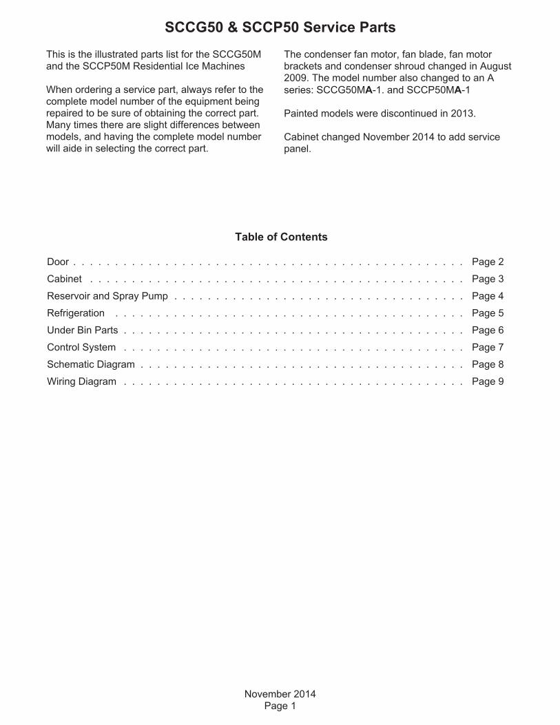
This is the illustrated parts list for the SCCG50Mand the SCCP50M Residential Ice Machines
When ordering a service part, always refer to thecomplete model number of the equipment beingrepaired to be sure of obtaining the correct part.Many times there are slight differences betweenmodels, and having the complete model numberwill aide in selecting the correct part.
The condenser fan motor, fan blade, fan motorbrackets and condenser shroud changed in August2009. The model number also changed to an A
series: SCCG50MA-1. and SCCP50MA-1
Painted models were discontinued in 2013.
Cabinet changed November 2014 to add servicepanel.
November 2014Page 1
SCCG50 & SCCP50 Service Parts
Table of Contents
Door . . . . . . . . . . . . . . . . . . . . . . . . . . . . . . . . . . . . . . . . . . . . . . . Page 2
Cabinet . . . . . . . . . . . . . . . . . . . . . . . . . . . . . . . . . . . . . . . . . . . . . Page 3
Reservoir and Spray Pump . . . . . . . . . . . . . . . . . . . . . . . . . . . . . . . . . . . Page 4
Refrigeration . . . . . . . . . . . . . . . . . . . . . . . . . . . . . . . . . . . . . . . . . . Page 5
Under Bin Parts . . . . . . . . . . . . . . . . . . . . . . . . . . . . . . . . . . . . . . . . . Page 6
Control System . . . . . . . . . . . . . . . . . . . . . . . . . . . . . . . . . . . . . . . . . Page 7
Schematic Diagram . . . . . . . . . . . . . . . . . . . . . . . . . . . . . . . . . . . . . . . Page 8
Wiring Diagram . . . . . . . . . . . . . . . . . . . . . . . . . . . . . . . . . . . . . . . . . Page 9

Door
Item Part
Number Number Description
1 Door panel kits. Kits includeitems 1 thru 8.
KDFW White panel, white handle
KDFWS White panel, SS handle
KDFB Black panel, black handle
kDFBS Black panel, SS handle
KDFS SS panel, SS handle
2 02-4433-01 Corner block, RH
3 02-4430-42 Handle, white
02-4430-52 Handle, black
02-4430-01 Handle, SS
4 02-4433-02 Corner block, LH
5 03-1531-01 Screw
6 03-3811-01 Screw
7 03-1410-07 Lockwasher
8 A39390-001 Support bracket
9 13-0949-03 Door gasket
10 03-1404-40 Screw
11 03-3818-01 Screw - hinge to cabinet
12 02-3866-04 Hinge - top left/bottom right
13 03-1404-24 Screw - hinge to door
14 02-3866-03 Hinge
15 03-1403-67 Screw
16 A39513-001 Door assembly, does not
include door panel or hinges
17 02-1875-07 Hole plug
18 02-4474-01 Hinge package
19 02-4415-20 Leg cap, pack of 4
20 11-0580-01 Magnet, door switch
October 2011Page 2
SCCG50 & SCCP50 Service Parts
1
3
4
55
5
2
56
2
7
84
9
10
15
11
1213
13
11
14
16
Items 17 and 19 included with item 18, packageshipped loose in bin.
18
1719
20
blitchy
Sticky Note
item 20, magnet with paint mark, paint mark is top side.

Cabinet
May 2016 Page 3
SCCG50 & SCCP50 Service Parts
1
12 A39364-003 Top hinge brkt, RH SS
A39364-007 Top hinge brkt, L & R SS*
12a 03-3813-01 Screw to fill holes
13 13-0943-05 Gasket
14 13-0943-03 Gasket strip
15 02-4426-01 Insulation pad
16 A39362-003 Top panel, SS
17 03-1403-86 Screw
18 A39618-001 SS cabinet & bin
19 A39385-003 Btm hinge brkt, L & R SS**
20 A34816-001 Bin stat bracket/scoop hldr
21
22
02-4391-03 Scoop A39615-001 Service panel
* changed 1/12 to add left and right hinge mounting.Painted parts no longer available.
1
1
1
1
22
2
4
5
6
7
17 8
9
10
11
1215
16
193
Item Part
Number Number Description
1 03-1404-10 Screw
2 A39363-001 Back panel
3 A39389-001 Utility routing bracket
4 12-1213-11 Snap bushing
5 A39392-001 Srv panel mntg bracket
6 02-4390-01 Kickplate
6a A39469-001 Kickplate, SS for outdoormodel
7 03-1403-86 Screw
8 02-4441-01 Panel handle
9 A39381-003 Service panel, SS
10 02-4392-01 Bin edging
11 03-3836-03 Screw
18
20, 21
13
14
6a

Reservoir and Spray Pump
November 2016Page 4
SCCG50 & SCCP50 Service Parts
1
23
4
15
5
6
7
8
17
1816
13
14
9
1211
10
Item Part
Number Number Description
1 12-2986-21 Water pump, incl item 1a
1a 02-1719-00 Fan blade
2 02-4379-01 Pump discharge hose
3 A39030-023 Water probe
4 02-4371-03 Spray platform
5 02-4368-01 Water Tee
6 13-0617-11 O-ring
7 02-4365-01 Front bracket
8 03-3892-01 Thumb screw
9 A39357-001 Curtain
10 02-4383-01 Clamp
11 02-4369-01 Drain cap, not used after 6/12
12 02-4428-01 Drain tube
13 02-4375-02 Evap bracket, left
14 02-4375-01 Evap bracket, right
15 02-4475-01 Grommet
16 02-4381-03 Clip
17 13-0617-04 O-ring
18 02-4381-01 Barbed fitting
19 02-4381-02 Spout
20 02-4373-01 O-ring
21 02-4370-21 Spray nozzle, kit. Set of 3 nozzles, o-rings, screws and nuts.
Item 22 is a plastic cover that fits over the evaporator tubing and cups. It was added in 2013.
22 02-4726-01 Evaporator cover
23 13-0840-01 Drain plug, changed 6/12.
24 02-4427-01 Reservoir
19
Rotate item 5 90degrees & lift toremove.
20, 21
1a
Reservoir Changed 6/12
23
24

Refrigeration
June 2008Page 5
SCCG50 & SCCP50 Service Parts
1 2
3
4
5
6
7
8
910
Item Part
Number Number Description
1 A39384-001 Suction line accumulator assy
2 11-0577-01 Thermistor
3 02-4376-01 Evaporator
4 18-8939-21 Compressor
Compressor includes overload, relay and drier
4a 18-8939-51 Overload
4b 18-8939-52 Relay
5 03-3821-01 Clip
6 03-1407-08 Washer
7 18-4700-28 Grommet
8 18-8940-01 Condenser
9 02-4416-01 Drier
10 11-0562-21 Hot gas valve
10a 11-0562-22 HGV coil
mtittelbach
Sticky Note
Thermistor holder: 03-1711-01

Under Bin Parts
March 2014Page 6
SCCG50 & SCCP50 Service Parts
DRAIN PUMPMODELS ONLY
GRAVITY DRAINMODELS ONLY
1 2
34
67
8
910
11
25
12
13
14
15
16
17
1920 21
22
30
29
23
24
23
27
25
26
Item Part
Number Number Description
1 12-2990-01 Inlet water sol valve
2 03-1531-01 Screw
3 12-2396-02 Fan motor
12-3024-01 Fan motor, A series
4 18-8941-01 Fan blade
02-4197-01 Fan blade, A series
5 A39555-001 Fan motor bracketA39555-001 bracket attaches to shroud. Use onprior models requires 2 brackets & A39359-001.
A39556-001 Fan motor bracket A series
6 A39359-001 Fan shroud
A39460-001 Fan shroud, A series
7 13-0909-01 Gasket, order 1 & cut to fit
8 02-4450-01 Air baffle
9 11-0617-21 Thermostat
10 A39379-001 Thermostat bracket
11 03-1403-16 Screw
12 03-1608-01 Leg leveler
12a 02-4415-01 Leg cap
13 02-1875-18 Hole plug
14 02-2814-13 Hose clamp
15 02-4412-01 Drain hose
16 02-2814-08 Hose clamp
17 16-0671-01 Elbow
18 A39462-021 Pump kit
19 A37334-001 Discharge hose
20 02-0534-02 Hose clamp
21 02-3522-01 Elbow
22 02-3374-01 Check valve
23 02-2814-13 Hose clamp
24 02-4413-01 Drain tube
25 02-3406-01 Barbed connector
26 05-0591-01 Switch hose
27 A39370-001 Switch bracket
28 11-0504-01 Pressure switch
29 03-3904-01 Spring
30 12-2503-21 Pump & motor only
2
18
28

Control System
SCCG50 & SCCP50 Service Parts
July 2013Page 7
Item Part
Number Number Description
1 03-3836-03 Screw
2 12-2924-01 Transformer
3 12-3077-01 Bulb
4 02-4380-01 Light cover
5 11-0574-01 Switch panel
6 12-3076-01 Bin light switch, bulbsocket and harness
7 11-0573-25 Controller
8 03-1531-01 Screw
9 02-4386-01 Cover
1
2
3
4
9
8
6
7
5
Not Shown:
NS1 12-3003-01 Bin stat harness
NS2 12-3000-02 Hi voltage harness, lower
NS3 12-3000-01 Hi voltage harness, upper
Note: If replacing the lower harness, always
replace the upper one too.
NS4 12-2992-01 Water sensor harness
Blitchy
Sticky Note
Power Cord: 12-1638-21

Schematic Diagram
June 2008Page 8
SCCG50 & SCCP50 Service Parts
SWITCHES ON THIS UNITSHOWN IN FREEZE CYCLEWITH DRAIN PUMP IN OPERATIONAND BIN DOOR CLOSED
BINLIGHT
BINLIGHTSWITCH
COMPRESSOR
SAFETYPRESSURE SWITCH
DRAIN PUMP PRESSURE SWITCH DRAIN
PUMP
HOT GASSOLENOID
FANMOTOR
L1 N
LINE
12V
TRANSFORMER
WATERPUMP
WATERSOLENOID
WATERCONDUCTIVITY SENSOR
SUCTIONTEMPERATURE THERMISTOR
ELECTRONIC CONTROL
BINLEVELCONTROL
IF DRAIN PUMPIS INSTALLED

Wiring Diagram
June 2008Page 9
SCCG50 & SCCP50 Service Parts
BIN LIGHT SWITCH
BINLIGHT
W
DRAINPUMPMOTOR
W
BK
R
BK
PUMPPRESSURESWITCH
NO
COMMNC
R
SAFETYPRESSURESWITCH
NO
COMMNC
W
PUMPMOTOR
BU
W
R/W
WATER
SOLENOID
W
BN
FANMOTOR
RHOT GAS
SOLENOID
GN/Y
GN/Y
YY
J221
J52 1
GN/Y
EARTH GROUND
V
3 2 1J1J4
123456
BK
W
O
TRANSFORMER
LOAD
LINE
J912 ELECTRONIC
CONTROL
SUCTIONTEMP. SENSOR
WATERCONDUCTIVITY SENSOR R
R
ONOFF
BINLEVEL
CONTROL
3 2J7
1
POWER IN
W
BKGN/Y
W
W
BK
BK/W1
3
SM
1
OVERLOAD
RELAY - CURRENT
COMPRESSOR
IF DRAIN PUMPIS INSTALLED