SCCG50 & SCCP50 Service Parts - Scotsman Home Ice · 19 02-4415-20 Leg cap, pack of 4 20 11-0580-01...
35
This is the illustrated parts list for the SCCG50M and the SCCP50M Residential Ice Machines When ordering a service part, always refer to the complete model number of the equipment being repaired to be sure of obtaining the correct part. Many times there are slight differences between models, and having the complete model number will aide in selecting the correct part. The condenser fan motor, fan blade, fan motor brackets and condenser shroud changed in August 2009. The model number also changed to an A series: SCCG50MA-1. and SCCP50MA-1 June 2008 Page 1 SCCG50 & SCCP50 Service Parts Table of Contents Door ............................................... Page 2 Cabinet ............................................. Page 3 Reservoir and Spray Pump ................................... Page 4 Refrigeration .......................................... Page 5 Under Bin Parts ......................................... Page 6 Control System ......................................... Page 7 Schematic Diagram ....................................... Page 8 Wiring Diagram ......................................... Page 9
Transcript of SCCG50 & SCCP50 Service Parts - Scotsman Home Ice · 19 02-4415-20 Leg cap, pack of 4 20 11-0580-01...
This is the illustrated parts list for the SCCG50Mand the SCCP50M Residential Ice Machines
When ordering a service part, always refer to thecomplete model number of the equipment beingrepaired to be sure of obtaining the correct part.Many times there are slight differences betweenmodels, and having the complete model numberwill aide in selecting the correct part.
The condenser fan motor, fan blade, fan motorbrackets and condenser shroud changed in August2009. The model number also changed to an A
series: SCCG50MA-1. and SCCP50MA-1
June 2008Page 1
SCCG50 & SCCP50 Service Parts
Table of Contents
Door . . . . . . . . . . . . . . . . . . . . . . . . . . . . . . . . . . . . . . . . . . . . . . . Page 2
Cabinet . . . . . . . . . . . . . . . . . . . . . . . . . . . . . . . . . . . . . . . . . . . . . Page 3
Reservoir and Spray Pump . . . . . . . . . . . . . . . . . . . . . . . . . . . . . . . . . . . Page 4
Refrigeration . . . . . . . . . . . . . . . . . . . . . . . . . . . . . . . . . . . . . . . . . . Page 5
Under Bin Parts . . . . . . . . . . . . . . . . . . . . . . . . . . . . . . . . . . . . . . . . . Page 6
Control System . . . . . . . . . . . . . . . . . . . . . . . . . . . . . . . . . . . . . . . . . Page 7
Schematic Diagram . . . . . . . . . . . . . . . . . . . . . . . . . . . . . . . . . . . . . . . Page 8
Wiring Diagram . . . . . . . . . . . . . . . . . . . . . . . . . . . . . . . . . . . . . . . . . Page 9

Door
Item Part
Number Number Description
1 Door panel kits. Kits includeitems 1 thru 8.
KDFW White panel, white handle
KDFWS White panel, SS handle
KDFB Black panel, black handle
kDFBS Black panel, SS handle
KDFS SS panel, SS handle
2 02-4433-01 Corner block, RH
3 02-4430-42 Handle, white
02-4430-52 Handle, black
02-4430-01 Handle, SS
4 02-4433-02 Corner block, LH
5 03-1531-01 Screw
6 03-3811-01 Screw
7 03-1410-07 Lockwasher
8 A39390-001 Support bracket
9 13-0949-03 Door gasket
10 03-1404-40 Screw
11 03-3818-01 Screw - hinge to cabinet
12 02-3866-04 Hinge - top left/bottom right
13 03-1404-24 Screw - hinge to door
14 02-3866-03 Hinge
15 03-1403-67 Screw
16 A39513-001 Door assembly, does not
include door panel or hinges
17 02-1875-07 Hole plug
18 02-4474-01 Hinge package
19 02-4415-20 Leg cap, pack of 4
20 11-0580-01 Magnet, door switch
October 2011Page 2
SCCG50 & SCCP50 Service Parts
1
3
4
55
5
2
56
2
7
84
9
10
15
11
1213
13
11
14
16
Items 17 and 19 included with item 18, packageshipped loose in bin.
18
1719
20

Cabinet
January 2012Page 3
SCCG50 & SCCP50 Service Parts
1
12 A39364-001 Top hinge brkt, RH white
A39364-002 Top hinge brkt, RH black
A39364-003 Top hinge brkt, RH SS
A39364-004 Top hinge brkt, LH white
A39364-005 Top hinge brkt, LH black
A39364-007 Top hinge brkt, R & L SS*
12a 03-3813-01 Screw to fill holes*
13 13-0943-05 Gasket
14 13-0943-03 Gasket strip
15 02-4426-01 Insulation pad
16 A39362-001 Top panel, white
A39362-002 Top panel, black
A39362-003 Top panel, SS
17 03-1403-86 Screw
18 A39378-001 White cabinet & bin
A39378-002 Black cabinet & bin
A39378-003 SS cabinet & bin
19 A39385-001 Btm hinge brkt, right white
A39385-002 Btm hinge brkt, right black
A39385-003 Btm hinge brkt, R & L SS*
A39385-004 Btm hinge brkt, left white
A39385-005 Btm hinge brkt, left black
A39385-006 Btm hinge brkt, left SS
20 A34816-001 Bin stat bracket/scoop hldr
21 02-4391-03 Scoop
* changed 1/2012 to add left & right hinge mounting
1
1
1
1
1
1
2
1
1
4
5
6
7
178
9
10
12
11
13
14
15
16
19
3
Item Part
Number Number Description
1 03-1531-01 Screw
2 A39363-001 Back panel
3 A39389-001 Utility routing bracket
4 12-1213-11 Snap bushing
5 A39392-001 Srv panel mntg bracket
6 02-4390-01 Kickplate
7 03-1403-86 Screw
8 02-4441-01 Panel handle
9 A39381-001 Service panel, white
A39381-002 Service panel, black
A39381-003 Service panel, SS
10 02-4392-01 Bin edging
11 03-3836-03 Screw
18
20, 21

Reservoir and Spray Pump
June 2012Page 4
SCCG50 & SCCP50 Service Parts
1
23
4
15
5
6
7
8
17
1816
13
14
9
1211
10
Item Part
Number Number Description
1 12-2986-21 Water pump, incl item 1a
1a 02-1719-00 Fan blade
2 02-4379-01 Pump discharge hose
3 A39030-023 Water probe
4 02-4371-03 Spray platform
5 02-4368-01 Water Tee
6 13-0617-11 O-ring
7 02-4365-01 Front bracket
8 03-3892-01 Thumb screw
9 A39357-001 Curtain
10 02-4383-01 Clamp
11 02-4369-01 Drain cap
12 02-4428-01 Drain tube
13 02-4375-02 Evap bracket, left
14 02-4375-01 Evap bracket, right
15 02-4475-01 Grommet
16 02-4381-03 Clip
17 13-0617-04 O-ring
18 02-4381-01 Barbed fitting
19 02-4381-02 Spout
20 02-4373-01 O-ring
21 02-4370-21 Spray nozzle, kit. Set of 3nozzles, o-rings, screws and nuts.
19
Rotate item 5 90degrees & lift toremove.
20, 21
1a

Refrigeration
June 2008Page 5
SCCG50 & SCCP50 Service Parts
1 2
3
4
5
6
7
8
910
Item Part
Number Number Description
1 A39384-001 Suction line accumulator assy
2 11-0577-01 Thermistor
3 02-4376-01 Evaporator
4 18-8939-21 Compressor
Compressor includes overload, relay and drier
4a 18-8939-51 Overload
4b 18-8939-52 Relay
5 03-3821-01 Clip
6 03-1407-08 Washer
7 18-4700-28 Grommet
8 18-8940-01 Condenser
9 02-4416-01 Drier
10 11-0562-21 Hot gas valve
10a 11-0562-22 HGV coil

Under Bin Parts
July 2009Page 6
SCCG50 & SCCP50 Service Parts
DRAIN PUMPMODELS ONLY
GRAVITY DRAINMODELS ONLY
1 2
34
67
8
910
11
25
12
13
14
15
16
17
1920 21
22
30
29
23
24
23
27
25
26
Item Part
Number Number Description
1 12-2990-01 Inlet water sol valve
2 03-1531-01 Screw
3 12-2396-02 Fan motor
12-3024-01 Fan motor, A series
4 18-8941-01 Fan blade
02-4197-01 Fan blade, A series
5 A39555-001 Fan motor bracketA39555-001 bracket attaches to shroud. Use onprior models requires 2 brackets & A39359-001.
A39556-001 Fan motor bracket A series
6 A39359-001 Fan shroud
A39460-001 Fan shroud, A series
7 13-0909-01 Gasket, order 1 & cut to fit
8 02-4450-01 Air baffle
9 11-0578-21 Thermostat
10 A39379-001 Thermostat bracket
11 03-1403-16 Screw
12 03-1608-01 Leg leveler
12a 02-4415-01 Leg cap
13 02-1875-18 Hole plug
14 02-2814-13 Hose clamp
15 02-4412-01 Drain hose
16 02-2814-08 Hose clamp
17 16-0671-01 Elbow
18 A39462-021 Pump kit
19 A37334-001 Discharge hose
20 02-0534-02 Hose clamp
21 02-3522-01 Elbow
22 02-3374-01 Check valve
23 02-2814-13 Hose clamp
24 02-4413-01 Drain tube
25 02-3406-01 Barbed connector
26 05-0591-01 Switch hose
27 A39370-001 Switch bracket
28 11-0504-01 Pressure switch
29 03-3904-01 Spring
30 12-2503-21 Pump & motor only
2
18
28

Control System
SCCG50 & SCCP50 Service Parts
November 2010Page 7
Item Part
Number Number Description
1 03-3836-03 Screw
2 12-2924-01 Transformer
3 12-2980-01 Bulb
4 02-4380-01 Light cover
5 11-0574-01 Switch panel
6 12-2980-03 Bin light sensor
7 11-0573-25 Controller
8 03-1531-01 Screw
9 02-4386-01 Cover
1
2
3
4
9
8
6
7
5
Not Shown:
NS1 12-2980-02 Bin light harness & socket
NS2 12-3003-01 Bin stat harness
NS3 12-3000-02 Hi voltage harness, lower
NS4 12-3000-01 Hi voltage harness, upper
NS5 12-2992-01 Water sensor harness
Blitchy
Sticky Note
Power Cord: 12-1638-21

Schematic Diagram
June 2008Page 8
SCCG50 & SCCP50 Service Parts
SWITCHES ON THIS UNITSHOWN IN FREEZE CYCLEWITH DRAIN PUMP IN OPERATIONAND BIN DOOR CLOSED
BINLIGHT
BINLIGHTSWITCH
COMPRESSOR
SAFETYPRESSURE SWITCH
DRAIN PUMP PRESSURE SWITCH DRAIN
PUMP
HOT GASSOLENOID
FANMOTOR
L1 N
LINE
12V
TRANSFORMER
WATERPUMP
WATERSOLENOID
WATERCONDUCTIVITY SENSOR
SUCTIONTEMPERATURE THERMISTOR
ELECTRONIC CONTROL
BINLEVELCONTROL
IF DRAIN PUMPIS INSTALLED

Wiring Diagram
June 2008Page 9
SCCG50 & SCCP50 Service Parts
BIN LIGHT SWITCH
BINLIGHT
W
DRAINPUMPMOTOR
W
BK
R
BK
PUMPPRESSURESWITCH
NO
COMMNC
R
SAFETYPRESSURESWITCH
NO
COMMNC
W
PUMPMOTOR
BU
W
R/W
WATER
SOLENOID
W
BN
FANMOTOR
RHOT GAS
SOLENOID
GN/Y
GN/Y
YY
J221
J52 1
GN/Y
EARTH GROUND
V
3 2 1J1J4
123456
BK
W
O
TRANSFORMER
LOAD
LINE
J912 ELECTRONIC
CONTROL
SUCTIONTEMP. SENSOR
WATERCONDUCTIVITY SENSOR R
R
ONOFF
BINLEVEL
CONTROL
3 2J7
1
POWER IN
W
BKGN/Y
W
W
BK
BK/W1
3
SM
1
OVERLOAD
RELAY - CURRENT
COMPRESSOR
IF DRAIN PUMPIS INSTALLED
This is the illustrated parts list for the SCCG30 andthe SCCP30 Residential Ice Machines
When ordering a service part, always refer to thecomplete model number of the equipment beingrepaired to be sure of obtaining the correct part.Many times there are slight differences betweenmodels, and having the complete model numberwill aide in selecting the correct part.
September 2009Page 1
SCCG30 & SCCP30 Service Parts
Table of Contents
Door . . . . . . . . . . . . . . . . . . . . . . . . . . . . . . . . . . . . . . . . . . . . . . . Page 2
Cabinet . . . . . . . . . . . . . . . . . . . . . . . . . . . . . . . . . . . . . . . . . . . . . Page 3
Reservoir and Spray Pump . . . . . . . . . . . . . . . . . . . . . . . . . . . . . . . . . . . Page 4
Under Bin Parts . . . . . . . . . . . . . . . . . . . . . . . . . . . . . . . . . . . . . . . . . Page 6
Control System . . . . . . . . . . . . . . . . . . . . . . . . . . . . . . . . . . . . . . . . . Page 7
Schematic Diagram . . . . . . . . . . . . . . . . . . . . . . . . . . . . . . . . . . . . . . . Page 8
Wiring Diagram . . . . . . . . . . . . . . . . . . . . . . . . . . . . . . . . . . . . . . . . . Page 9

Door
Item Part
Number Number Description
1 Door panel kit. Kit includesitems 1 thru 8.
KDFS SS panel, SS handle
2 02-4433-01 Corner block, RH
3 02-4430-01 Handle, SS
4 02-4433-02 Corner block, LH
5 03-1531-01 Screw
6 03-3811-01 Screw
7 03-1410-07 Lockwasher
8 A39390-001 Support bracket
9 13-0949-03 Door gasket
10 03-1404-40 Screw
11 03-3818-01 Screw - hinge to cabinet
12 02-3866-04 Hinge - top left/bottom right
13 03-1404-24 Screw - hinge to door
14 02-3866-03 Hinge
15 03-1403-67 Screw
16 A39513-001 Door assembly, does not
include door panel or hinges
17 02-4415-20 Leg cap, pack of 4
18 02-1875-07 Hole plug
19 02-4474-01 Hinge package
May 2010Page 2
SCCG30 & SCCP30 Service Parts
1
3
4
55
5
2
56
2
7
84
9
10
15
11
1213
13
11
14
16
19
17 18

Cabinet
January 2012Page 3
SCCG30 & SCCP30 Service Parts
1
12 A39364-001 Top hinge brkt, RH white
A39364-002 Top hinge brkt, RH black
A39364-003 Top hinge brkt, RH SS
A39364-004 Top hinge brkt, LH white
A39364-005 Top hinge brkt, LH white
A39364-007 Top hinge brkt, L & R SS*
12a 03-3813-01 Screw to fill holes
13 13-0943-05 Gasket
14 13-0943-03 Gasket strip
15 02-4426-01 Insulation pad
16 A39362-001 Top panel, white
A39362-002 Top panel, black
A39362-003 Top panel, SS
17 03-1403-86 Screw
18 A38378-001 White cabinet & bin
A39378-002 Black cabinet & bin
A39378-003 SS cabinet & bin
19 A39385-001 Btm hinge brkt, right white
A39385-002 Btm hinge brkt, right black
A39385-003 Btm hinge brkt, L & R SS**
A39385-004 Btm hinge brkt, left white
A39385-005 Btm hinge brkt, left black
A39385-006 Btm hinge brkt, left SS
20 A34816-001 Bin stat bracket/scoop hldr
21 02-4391-01 Scoop
* changed 1/12 to add left and right hinge mounting
1
1
1
1
1
1
2
1
1
4
5
6
7
17 8
9
10
11
12
13
14
15
16
19
3
Item Part
Number Number Description
1 03-1531-01 Screw
2 A39363-001 Back panel
3 A39389-001 Utility routing bracket
4 12-1213-11 Snap bushing
5 A39392-001 Srv panel mntg bracket
6 02-4390-01 Kickplate
7 03-1403-86 Screw
8 02-4441-01 Panel handle
9 A39381-001 Service panel, white
A39381-002 Service panel, black
A39381-003 Service panel, SS
10 02-4392-01 Bin edging
11 03-3836-03 Screw
18
20, 21
Reservoir and Spray Pump
June 2012Page 4
SCCG30 & SCCP30 Service Parts
1
2
4
15
5
6
7
8
17
1816
13
14
9
1211
10
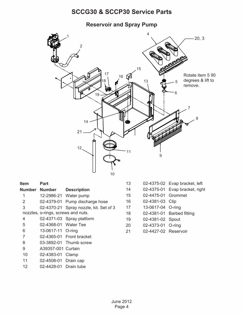
Item Part
Number Number Description
1 12-2986-21 Water pump
2 02-4379-01 Pump discharge hose
3 02-4370-21 Spray nozzle, kit. Set of 3nozzles, o-rings, screws and nuts.
4 02-4371-03 Spray platform
5 02-4368-01 Water Tee
6 13-0617-11 O-ring
7 02-4365-01 Front bracket
8 03-3892-01 Thumb screw
9 A39357-001 Curtain
10 02-4383-01 Clamp
11 02-4508-01 Drain cap
12 02-4428-01 Drain tube
13 02-4375-02 Evap bracket, left
14 02-4375-01 Evap bracket, right
15 02-4475-01 Grommet
16 02-4381-03 Clip
17 13-0617-04 O-ring
18 02-4381-01 Barbed fitting
19 02-4381-02 Spout
20 02-4373-01 O-ring
21 02-4427-02 Reservoir
19
Rotate item 5 90degrees & lift toremove.
20, 3
21

Refrigeration System
July 2010Page 5
SCCG30 & SCCP30 Service Parts
Item Part
Number Number Description
1 A39396-001 Suction line accumulator assy
2 02-4376-02 Evaporator
3 18-8776-21 Compressor
Compressor includes overload, relay and drier
3a 18-8776-52 Overload
3b 18-8776-51 Relay
4 03-3821-01 Clip
5 03-1407-08 Washer
6 18-4700-28 Grommet
7 18-8940-01 Condenser
8 02-3490-01 Drier
9 11-0562-21 Hot gas valve
9a 11-0562-22 HGV coil
2
1
3
7
9
8
4, 5, 6

Under Bin Parts
September 2009Page 6
SCCG30 & SCCP30 Service Parts
DRAIN PUMPMODELS ONLY
GRAVITY DRAINMODELS ONLY
Item Part
Number Number Description
1 12-2990-01 Inlet water sol valve
2 03-1531-01 Screw
3 12-3024-01 Fan motor
4 02-4197-01 Fan blade
5 A39556-001 Fan motor bracket
6 A39460-001 Fan shroud
7 13-0909-01 Gasket, order 1 & cut to fit
8 02-4450-01 Air baffle
9 11-0504-01 Pressure switch
10 03-3904-01 Spring
11 12-2503-21 Pump & motor only
12 03-1608-01 Leg leveler
13 02-1875-18 Hole plug
14 02-2814-13 Hose clamp
15 02-4412-01 Drain hose
16 02-2814-08 Hose clamp
17 16-0671-01 Elbow
18 A39462-021. Pump kit
19 A37334-001 Discharge hose
20 02-0534-02 Hose clamp
21 02-3522-01 Elbow
22 02-3374-01 Check valve
23 02-2814-13 Hose clamp
24 02-4413-01 Drain tube
25 02-3406-01 Barbed connector
26 05-0591-01 Switch hose
27 A39370-001 Switch bracket
1 2
3
4
67
8
5
12
13
14
15
16
17
1920 21
22
11
10
23
24
23
27
25
26
2
18
9

Control System
September 2009Page 7
SCCG30 & SCCP30 Service Parts
Item Part
Number Number Description
1 02-4436-01 Graphic overlay
2 12-2991-01 Power switch
3 02-4386-01 Cover
4 12-2985-01 Timer
5 11-0584-21 Cube size thermostat
6 11-0578-21 Bin thermostat
Not Shown:
NS1 12-3005-02 Hi voltage harness, lower
NS2 12-3005-01 Hi voltage harness, upper
6
5
4
2
13

Schematic Diagram
September 2009Page 8
SCCG30 & SCCP30 Service Parts
HARVEST TIMEADJUSTABLE FROM 120 TO 300 SEC.FACTORY SET TO 170 SEC.
ON / OFFSWITCH
TIMER 2
1
6
C
NC
NO
CUBE SIZECONTROL(INITIATETIMER)
COMPRESSOR
SWITCHES ON THIS UNITSHOWN IN TIMED PORTIONOF THE FREEZE CYCLEWITH DRAIN PUMP IN OPERATION
BIN LEVELCONTROL
SAFETYPRESSURE SWITCH
DRAIN PUMP PRESSURE SWITCH DRAIN
PUMP
HOT GASSOLENOID
FANMOTOR
L1 N
WATERPUMP
WATERSOLENOID
IF DRAIN PUMPIS INSTALLED

Wiring Diagram
September 2009Page 9
SCCG30 & SCCP30 Service Parts
BU
Y
TIMER
ON-OFFSWITCHBK
BK
W
BK/W
BK
2
1
6
C
NC
NO
COMPRESSOR
RELAY - CURRENT
OVERLOAD
1
MS
3
1
Y21
3
CONTROL
CUBE SIZE
W
DRAINPUMPMOTOR
W
BK
R
BK
PUMPPRESSURESWITCH
NO
COMMNC
R
SAFETYPRESSURESWITCH
NO
COMMNC
W
PUMPMOTOR
BU
W
W
R/W
WATER
SOLENOID
FANMOTOR
R
HOT GAS
SOLENOID
BN
GN/Y
EARTH GROUND
ONOFF
BINLEVEL
CONTROL
POWER IN
W
BKGN/Y
W
W
IF DRAIN PUMPIS INSTALLED

SCOTSMAN ICE SYSTEMS
775 Corporate Woods Parkway, Vernon Hills, IL 60061
800-533-6006
www.scotsman-ice.com
17-3264-02

DCE33 SERVICE PARTS
The section contains the parts list for the DCE33. The DCE33 has been manufactured in either a White,
Black or Stainless Steel finish.
A "D" series model was introduced in 2011 (as in DCE33A-1BD), it has a different timer and wiring
diagram.
Please check the part description before ordering any part.
Table of Contents
Cabinet ····································································································································· Page 2
Pump, Evaporator, Storage Bin ································································································ Page 3
Drain Pump Components ········································································································· Page 4
Condensing Unit ······················································································································· Page 5
Reservoir ·································································································································· Page 6
CONTROL BOX - all models except DCE33A-1BD, DCE33PA-1BD, DCE33A-1SSD or
DCE33PA-1SSD ······················································································································· Page 7
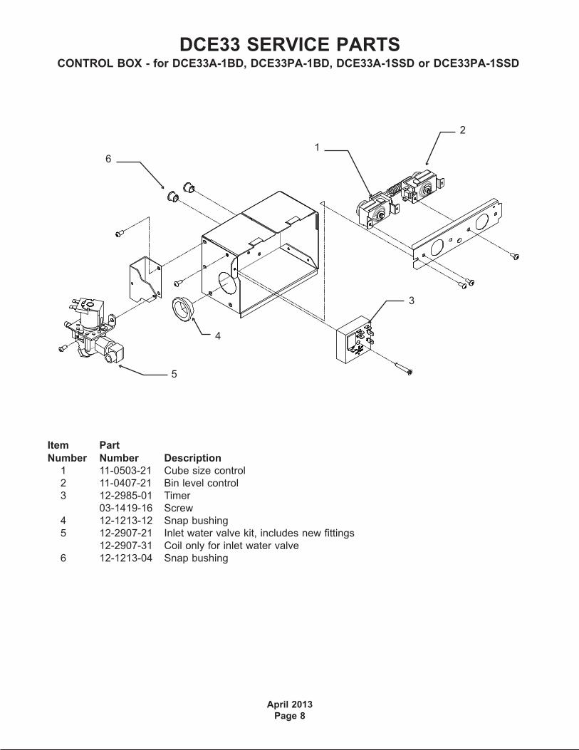
CONTROL BOX - for DCE33A-1BD, DCE33PA-1BD, DCE33A-1SSD or DCE33PA-1SSD ··· Page 8
Compressor ······························································································································ Page 9
Drain Pump Model Wiring Diagram - Prior to August 2000 ····················································· Page 11
Gravity Drain Model Wiring Diagram - Prior to August 2000 ··················································· Page 12
Drain Pump Model Wiring Diagram after August 2000 up to D series ···································· Page 13
Gravity Drain Model Wiring Diagram after August 2000 up to D series ·································· Page 14
Wiring Diagram for DCE33A-1BD, DCE33PA-1BD, DCE33A-1SSD or DCE33PA-1SSD ······· Page 15
Schematic Diagram DCE33A-1BD, DCE33PA-1BD, DCE33A-1SSD or DCE33PA-1SSD ····· Page 16

DCE33 SERVICE PARTS
September 2013
Page 2
1,
includes items
2,3,4,5,6, & 7
2
9
17
2214
13
16
20
10
4
21
15
3,
includes 5
8
11
7
19
7
6
18
5
8a
8b
23
Item Part
Number Number Description
1. A32117-003 White Door Assembly
A32117-010 Black door assembly
A32117-011 Stainless door assembly
2. 13-0826-04 Gasket
3. A29043-001 Alum. Door Handle (white)
A29043-003 Alum. Door Handle, (black)
4. 03-1607-01 Head Screw (2)
5. 15-0730-01 Nameplate strip (white)
15-0730-02 Nameplate strip (black)
6. 15-0648-01 Alum. Hinge Fill Plate, Rt.
15-0648-02 Alum. Hinge Fill Plate, Lt.
7. 03-1418-24 Screw (10)
8. 13-0828-01 Gasket (white)
13-0828-02 Gasket (grey)
8a 03-1419-08 Screw - not for ss
03-1404-26 Screw for SS cabinets
8b 02-2701-01 Spacer
9. 03-1419-26 Screw, black
03-1419-29 Screw, white
10. 15-0799-01 Hinge
Item Part
Number Number Description
11. 15-0799-02 Hinge
13. 02-3141-01 Knob, Bin Thermo
14. A34877-002 Cont Box cover - white
A34877-003 Cont Box cover - black
A40162-001 Cont Box cover - SS
14a 17-3465-01 Bin level control label
15. 03-1404-07 Screw (6)
16. 02-2243-02 Kickplate - black
17. A29102-001 Rear Panel
18. 03-1404-08 Screw (9)
19. 02-2481-01 Plug (6) (white)
02-2481-02 Plug, black
02-1874-11 Plug, nickel
20. A38803-021 Cabinet (white)
A38803-022 Cabinet (black)
for flat head screws, use began w/sn 05111320015862
A40159-001 Cabinet (stainless steel)
21. A26787-001 Insulation (in Bag)
22. 12-2571-01 Power cord & wire harness
12-1638-21 For D series
23 03-1431-00 Screw, pan head
03-1419-29 Flat head screw, white
Note: Items 20 and 23. Item 20 only availablefor use with flat head screws. Prior cabinets
used pan head screws.
Cabinet
Note for SSD models only: Magnetic stripsinside cabinet - 02-4738-01 and 02-4738-02.

DCE33 SERVICE PARTS
September 2011
Page 3
14
SCOOP
(not shown)
PN: 02-3070-01(plastic)
08-0664-01(metal)
4
51
8
15
16
12
7
9
11
6
13
1
17, includes 3, & res. drain
20
19
18
3
2
Pump, Evaporator, Storage Bin
21
17a,17b,17c
2b
2c
2a
Item Part
Number Number Description
1. 02-2274-01 Platen Cover
2. 13-0674-01 Tube, 37"
2a A27027-001 Copper inlet tube
2b no number Tube holder
2c 02-1727-01 Hose clamp
3. A34816-001 Bin Thermostat bracket
4. 02-3489-20 Evaporator, does NOT
include suction line and accumulator
5. A36699-020 Evaporator, Complete
6. 13-0899-01 Res. drain hose
7. 13-0674-16 Tube, 5/8" Req. 4.25"
8. 13-0674-15 Tube,1/2", Req 3.25"
9. 13-0674-15 Tube, 1/2", Req. 3-5/8"
10. 02-1775-02 Clamp (2)
11. 02-0534-02 Clamp (4)
12. 02-1719-00 Fan Blade
13. A30625-001 Spray Pump
14. 13-0687-00 Gasket
15. 03-1719-01 Screw
16. no longer used Speed Nut (2)
17. A36930-020 Bin Assembly, includes
reservoir drain hose & drain fittings
17a 02-3323-01 Drain fitting
(foamed in bin)
17b 13-0617-13 O-Ring
17c 03-1394-05 Pal nut
18 12-2569-03 Clip, Hot Gas Valve
19. 12-2569-02 Coil, Hot Gas Valve
replaces coils that have encapsulated wires
11-0562-22 Coil, hot gas valve
replaces coils that have terminals
20. 11-0562-21 Hot Gas Valve kit
21 02-3490-01 Drier

DCE33 SERVICE PARTS
April 2013
Page 4
Drain Pump Components
3
1
2
7
6
10
4
5
9
13
12
11
Item Part
Number Number Description
1. A36892-020 Drain Pump Kit, for all except DCE33A-1BD and DCE33A-1SSD
A39885-001 Drain pump kit, for DCE33A-1BD or DCE33A-1SSD
use to convert any DCE33 gravity model to pump type. Pump must be ordered separately.
2 12-2503-21 Drain pump only,
use to replace drain pumps or w/kit to convert.
Pump Kit Service Parts
3 02-3369-01 Inlet hose
4 02-3522-01 Elbow
5 02-3374-01 Check valve
6 13-0617-08 O-ring
7 11-0504-01 Pressure switch
8 obsolete Impeller & housing kit
9 A37334-001 Discharge hose
10 05-0591-01 Switch hose
11 A36746-001 Mounting bracket
12 02-3406-01 Barbed connector
13 02-2814-11 Clamp
14 12-2580-01 Harness
12-3001-01 Harness, for converted-to-pump DCE33A-1BD, DCE33PA-1D, DCE33A-1SSD
or DCE33PA-1SSD
15 03-3904-01 Check valve spring
15

DCE33 SERVICE PARTS
April 2013
Page 5
Item Part
Number Number Description
1. 03-1404-08 Screw (4)
2. 18-3710-01 Fan Blade
3. A28798-001 Fan Motor Bracket
4. 12-2396-21 Fan Motor
18-8752-10 Blade pad
18-8752-11 Blade nut
5. 02-2871-01 Fan Shroud
6. 18-3729-01 Condenser
7. 18-4700-28 Grommet
8. 03-1608-01 Leg Leveler
9. 03-1407-08 Washer
03-3821-01 Clip
10. A29015-001 Bracket
Item Part
Number Number Description
11 12-1213-10 Bushing
12 A37732-001 Upper base plate
13 13-0609-00 Foam tape
14 A28921-001 Lower base plate
A38638-001 Lower base plate
use began w/sn 05111320015862
Support brackets part of item 12
A40164-001 Base pan for -1SSD
15 03-1531-01 Screw
7
4
9
8
5
6
2
10
3
1
1
12
13
14
15
Condensing Unit
Support Bracket
11

DCE33 SERVICE PARTS
September 2011
Page 6
Item Part
Number Number Description
1. 02-2479-21 Curtain
2. A24155-001 Curtain stiffener
3. 03-1404-16 Screw
4. 02-1841-00 Nozzle
5. A09543-000 Spinner
6. 02-1840-00 Jet Base
7. A22518-000 Cube Chute
Item Part
Number Number Description
8. 13-0617-08 O-ring
9. 02-2704-01 Spray Bar Assembly
10. 05-0593-01 SS nipple
11. 13-0617-01 O-ring
12. 02-1923-01 Bin Insert
13 A22532-001 Bin insert assy
3
1
2
124
5
6
8
9
10
11
7
13
Reservoir

DCE33 SERVICE PARTS
April 2013
Page 7
4
6
8
7
3
1
2
8
9
11
10
12
Blue Valve Shown
Item Part
Number Number Description
1. A25981-001 Terminal Board
2. 03-1638-01 Screw
3. 12-1980-01 Timer And Switch
4. 11-0503-21 Cube Size Control
5. 11-0407-21 Bin Level Control
02-3141-01 Knob for item 5
6. 12-2907-21 Inlet Water Valve Kit
(includes new fittings)
12-2907-31 Coil only for brass valve
12-2410-31 Coil only for plastic valve
Item Part
Number Number Description
7. 12-1213-12 Bushing
8. 03-1403-17 Screw
9 12-1213-04 Snap bushing
10 03-1638-02 Screw
11 02-2242-06 Stand off
12 02-2242-05 Stand off
Not Shown
13 A39918-001 Kit to retrofit electronic
timer to prior model.
CONTROL BOX - all models except DCE33A-1BD, DCE33PA-1BD, DCE33A-1SSD orDCE33PA-1SSD
Brass Inlet Water Valve Mounts toControl Box As Shown
5
DCE33 SERVICE PARTS
April 2013
Page 8
CONTROL BOX - for DCE33A-1BD, DCE33PA-1BD, DCE33A-1SSD or DCE33PA-1SSD
Item Part
Number Number Description
1 11-0503-21 Cube size control
2 11-0407-21 Bin level control
3 12-2985-01 Timer
03-1419-16 Screw
4 12-1213-12 Snap bushing
5 12-2907-21 Inlet water valve kit, includes new fittings
12-2907-31 Coil only for inlet water valve
6 12-1213-04 Snap bushing
2
1
3
5
6
4

DCE33 SERVICE PARTS
September 2011
Page 9
Item Part
Number Number Description
1. 18-8776-21 Compressor Kit, Includes Relay, Overload, Instructions
2. 18-8776-51 Relay
3 18-8776-52 Overload
4. 18-8776-54 Cover
Compressor
12
3
4

DCE33 SERVICE PARTS
September 2011
Page 10
Kit PartsK-SS Door Sleeve Kit
02-3846-01 Sleeve
02-3847-01 Handle
03-1403-50 Screw for handle
03-1407-06 Washer
03-1410-03 Lockwasher
03-3811-01 Screw

DCE33 SERVICE PARTS
September 2011
Page 11
Drain Pump Model Wiring Diagram - Prior to August 2000

DCE33 SERVICE PARTS
September 2011
Page 12
Gravity Drain Model Wiring Diagram - Prior to August 2000

DCE33 SERVICE PARTS
September 2011
Page 13
Drain Pump Model Wiring Diagram after August 2000 up to D series

DCE33 SERVICE PARTS
September 2011
Page 14
Gravity Drain Model Wiring Diagram after August 2000 up to D series

Wiring Diagram for DCE33A-1BD, DCE33PA-1BD, DCE33A-1SSD or DCE33PA-1SSD
DCE33 SERVICE PARTS
April 2013
Page 15
BU
Y
TIMER
BK
BK
W
BK/W
BK
2
1
6
C
NC
NO
COMPRESSOR
RELAY - CURRENT
OVERLOAD
1
MS
3
1
Y21
3
CONTROL
CUBE SIZE
W
DRAINPUMPMOTOR
W
BK
R
BK
PUMPPRESSURESWITCH
NO
COMMNC
R
SAFETYPRESSURESWITCH
NO
COMMNC
W
PUMPMOTOR
BU
W
W
R/W
WATER
SOLENOID
FANMOTOR
R
HOT GAS
SOLENOID
BN
GN/Y
EARTH GROUND
ONOFF
BINLEVEL
CONTROL
POWER IN
W
BKGN/Y
W
W
IF DRAIN PUMPIS INSTALLED

Schematic Diagram DCE33A-1BD, DCE33PA-1BD, DCE33A-1SSD or DCE33PA-1SSD
DCE33 SERVICE PARTS
April 2013
Page 16
HARVEST TIMEADJUSTABLE FROM 120 TO 300 SEC.FACTORY SET TO 170
TIMER 2
1
6
C
NC
NO
CUBE SIZECONTROL(INITIATETIMERSWITCH)
COMPRESSOR
SWITCHES ON THIS UNITSHOWN IN TIMED PORTIONOF THE FREEZE CYCLEWITH DRAIN PUMP IN OPERATION
BIN LEVELCONTROL
SAFETYPRESSURE SWITCH
DRAIN PUMP PRESSURE SWITCH DRAIN
PUMP
HOT GASSOLENOID
FANMOTOR
L1 N
WATERPUMP
WATERSOLENOID
IF DRAIN PUMPIS INSTALLED