SCA2003-51: Development of a Portable X -Ray Computed Tomographic Imaging System for...
7
SCA2003-51: Development of a Portable X-Ray Computed Tomographic Imaging System for Drill-Site Investigation of Recovered Core Barry M. Freifeld, Timothy J. Kneafsey, Liviu Tomutsa, and Jacob Pruess Lawrence Berkeley National Laboratory, Berkeley CA 94720, USA This paper was prepared for presentation at the International Symposium of the Society of Core Analysts held in Pau, France, 21-24 September 2003 ABSTRACT A portable x-ray computed tomography (CT) system was constructed for imaging core at drill sites. Performing drill-site-based x-ray scanning and CT analysis permits rapid evaluation of core properties (such as density, lithologic structure, and macroporosity distribution) and allows for real-time decision making for additional core-handling procedures. Because of the speed with which scanning is performed, systematic imaging and electronic cataloging of all retrieved core is feasible. Innovations (such as a novel clamshell shielding arrangement integrated with system interlocks) permit safe operation of the x-ray system in a busy core handling area. The minimization of the volume encapsulated with shielding reduces the overall system weight and facilitates instrument portability. The x-ray system as originally fabricated had a 110 kV x-ray source with a fixed 300- micron focal spot size. A 15 cm image intensifier with a cesium iodide phosphor input screen was coupled to a CCD for image capture. The CT system has since been modified with a 130 kV micro-focal x-ray source. With the x-ray system’s variable focal spot size, high-resolution studies (10-micron resolution) can be performed on core plugs and coarser (100-micron resolution) images can be acquired of whole drill cores. The development of an aluminum compensator has significantly improved the dynamic range and accuracy of the system. An x-ray filter has also been incorporated, permitting rapid acquisition of multi-energy scans for more quantitative analysis of sample mineralogy. The x-ray CT system has operated reliably under extreme field conditions, which have varied from shipboard to arctic. INTRODUCTION The purpose of this extended abstract is to detail a portable x-ray computed tomography (CT) system that can be used for analysis of core at the drill site. A practical drill-site CT must be portable, rugged, and fast enough to keep up with a reasonable flow of recovered core. There are numerous benefits to performing CT imaging at the drill site (as opposed to a dedicated laboratory). Since all core can be imaged and interpreted in a consistent fashion, the on site geologist has a quantitative aid for interpreting the morphology and physical properties of recovered cores. Downhole logs, which are typically available soon after the tools are run, can be compared with CT measurements, and differences can be
Transcript of SCA2003-51: Development of a Portable X -Ray Computed Tomographic Imaging System for...

SCA2003-51: Development of a Portable X-Ray Computed Tomographic Imaging System for Drill-Site Investigation of
Recovered Core
Barry M. Freifeld, Timothy J. Kneafsey, Liviu Tomutsa, and Jacob Pruess Lawrence Berkeley National Laboratory, Berkeley CA 94720, USA
This paper was prepared for presentation at the International Symposium of the Society of Core
Analysts held in Pau, France, 21-24 September 2003 ABSTRACT A portable x-ray computed tomography (CT) system was constructed for imaging core at drill sites. Performing drill-site-based x-ray scanning and CT analysis permits rapid evaluation of core properties (such as density, lithologic structure, and macroporosity distribution) and allows for real-time decision making for additional core-handling procedures. Because of the speed with which scanning is performed, systematic imaging and electronic cataloging of all retrieved core is feasible. Innovations (such as a novel clamshell shielding arrangement integrated with system interlocks) permit safe operation of the x-ray system in a busy core handling area. The minimization of the volume encapsulated with shielding reduces the overall system weight and facilitates instrument portability. The x-ray system as originally fabricated had a 110 kV x-ray source with a fixed 300- micron focal spot size. A 15 cm image intensifier with a cesium iodide phosphor input screen was coupled to a CCD for image capture. The CT system has since been modified with a 130 kV micro-focal x-ray source. With the x-ray system’s variable focal spot size, high-resolution studies (10-micron resolution) can be performed on core plugs and coarser (100-micron resolution) images can be acquired of whole drill cores. The development of an aluminum compensator has significantly improved the dynamic range and accuracy of the system. An x-ray filter has also been incorporated, permitting rapid acquisition of multi-energy scans for more quantitative analysis of sample mineralogy. The x-ray CT system has operated reliably under extreme field conditions, which have varied from shipboard to arctic. INTRODUCTION The purpose of this extended abstract is to detail a portable x-ray computed tomography (CT) system that can be used for analysis of core at the drill site. A practical drill-site CT must be portable, rugged, and fast enough to keep up with a reasonable flow of recovered core. There are numerous benefits to performing CT imaging at the drill site (as opposed to a dedicated laboratory). Since all core can be imaged and interpreted in a consistent fashion, the on site geologist has a quantitative aid for interpreting the morphology and physical properties of recovered cores. Downhole logs, which are typically available soon after the tools are run, can be compared with CT measurements, and differences can be
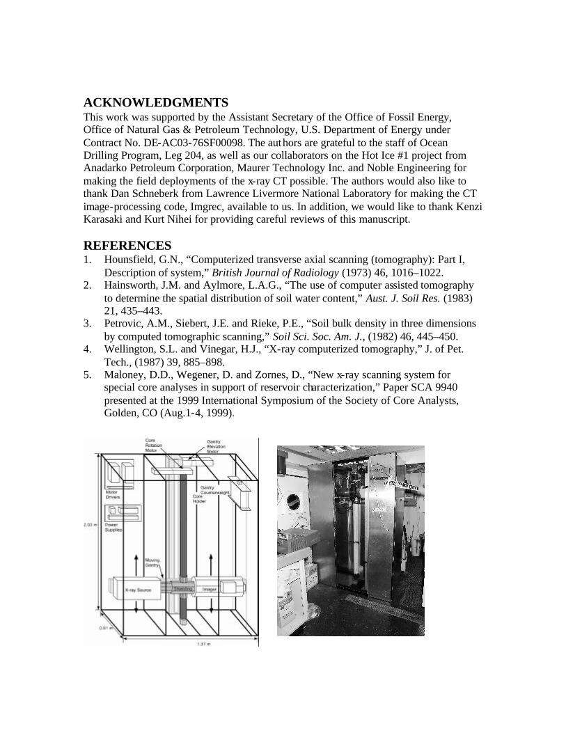
investigated prior to field demobilization. The CT can also aid in selecting core plug locations by showing features not visible on the surface of the core. Finally, if the core is damaged or degraded during shipment and storage, then CT imaging can provide baseline information on the state of the core as recovered. The motivation for our development of a portable CT system was to permit imaging of unstable gas hydrate bearing cores. Gas hydrate, if not stabilized at high pressures and low temperatures will rapidly disassociate, leaving behind water and methane gas. X-ray CT dates back to the seminal work by Hounsfield in 1972 [1]. It was not until the early 1980s that soil scientists Hainsworth and Aylmore [2] began to use CT to investigate water saturation distribution in soils, and Petrovic et al. [3] used CT for analyzing the spatial variation in soil density. Similarly, the work of Wellington and Vinegar [4] showed the versatility of CT in characterizing the spatial variation of numerous core properties, such as density, porosity, and mineralogical distribution important to the field of petroleum engineering. More significantly, their work detailed the use of CT to perform dynamic coreflood experiments, allowing scientists to gain insight into multiphase reservoir processes. While the medical CT has been the instrument most used within the earth sciences community for imaging core, it is limited by its weight, cost and infrastructure requirements. Recently, both commercially available and unique laboratory systems have been fabricated with geometries optimized for core imaging [5]. These specialized machines take into account the long, slender geometry of geologic core and use fan-beam and cone-beam geometries for quickly imaging greater volumes. The CT system presented here incorporates several novel features that both improve image quality and make practical a truly portable whole-round core scanner. EQUIPMENT A schematic layout and a picture of the portable CT are shown in Figure 1. The object to be imaged, a geological core, is rotated around its vertical axis. The gantry holding the x-ray source and detector is raised and lowered by a belt driven actuator to facilitate imaging selected regions of the core. The x-ray source has a tungsten target and a 250 micron beryllium window, delivering up to 130 kV at 65 watts. It has a variable focal spot size that increases from 5 microns at 4 watts to 100 microns at 65 watts. Computer control permits automatic adjustment of both anode voltage and current. To be able to efficiently capture the cone-beam projection of a core in a holder with a diameter as large as 100 mm, we chose a 150 mm cesium iodide image intensifier. Radiographs of a 10 cm long section of core can be made with a resolution of 200 microns using a standard industrial CCD, such as the Sony XC-75 that we employed. With a 1024 x 1024 scientific camera, a user can increase resolution to 100 microns. To reduce noise and increase the sensitivity and dynamic range of the system, we took great care to optimize the x-ray beam path for core imaging. A beam collimator mounted on the x-ray source minimizes albedo, which degrades image quality. As part of the beam

collimator, a computer-controlled copper shutter reduces the soft x-ray content of the beam at energies greater than 100 kV. This filtering reduces the influence that the imaged object’s effective atomic number has on voxel amplitude and leads to more precise estimates of bulk density. Multiple frames of the same image are acquired and averaged to reduce camera noise, which is inversely proportional to the square root of the number of frames averaged. Ten frames acquired over a 0.4-second period was found to be a reasonable trade-off between speed and image quality. An aluminum compensator was designed to reduce the variation in signal intensity that occurs as x-rays penetrate the variable thickness of a cylindrical core. Figure 2 shows a detailed schematic of the x-ray beam path along with a picture of the compensator. The compensator profile was designed by simulating ray paths from the source to the image intensifier. To calculate ray-path attenuation, we used the known geometry of our system, including the aluminum core holders, and assumed a constant core density. The calculated compensator profile required to make an image of uniform intensity across the image intensifier was programmed into a wire EDM machine, which cut a complex profile into an aluminum blank. The image reconstruction software, Imgrec (developed at Lawrence Livermore National Laboratory), was employed to perform convolution back projection and Feldkamp reconstructions of the acquired cone-beam radiographs. The convolution back-projection algorithm is used for rapid analysis of acquired radiographs (a few seconds to reconstruct a single horizontal slice), but since it does not account for the large angles of the cone-beam, it is accurate for imaging only the middle section of core. The Feldkamp algorithm corrects for the divergent cone beam angles and can provide an accurate reconstruction of 180 images of a 10 cm section of core in 20 minutes, using a 2.4 GHz Pentium IV processor. Several innovations (patent pending) in the CT system make it both safe and portable. The key to transportability was minimizing the volume enclosed within the heavy lead shielding. The usual shielding method for a fixed system, encapsulation of the entire unit or room within a lead enclosure, would have resulted in a unit of limited portability. Since both the x-ray source and the image intensifier were supplied by the vendors with adequate shielding, we optimized the additional shielding required to enclose the x-ray path by forming a cross that traveled along the core axis (Figure 1). One arm of the cross encompassed the main x-ray beam, and the other arm reduced radiation scattered along the core axis. To permit loading and unloading of the core, the vertical arm of the cross was split and was able to open and close by telescoping back over the horizontal arm. To meet the United States radiological requirements for a cabinet safe system (U.S. Title 21 Code of Federal Regulations 1020.40) we located redundant safety interlocks both on the access door and the shielding to prevent energizing the unit while personnel are manipulating the core.
CALIBRATION To use the x-ray system for quantitative analysis, the system requires proper calibration. Figure 3 shows a reconstructed image of typical reference standards used during field applications. This reference contains three standards: two LDPE bottles filled with known density materials in a dry 20/40 graded sand matrix. The graph in Figure 3 shows the resulting calibration used for interpreting material density. While this standard is good for when Compton scattering predominates (above 100 kV), lower energies are more sensitive to photoelectric absorption and may need to be corrected for effective atomic number [4]. To permit interpretation of both bulk density and atomic number, multi-energy calibrations with reference materials of both known density and effective atomic number are performed. One such set of reference standards that we used consists of mixtures of varying quantities of dodecane and bromodecane. APPLICATIONS The x-ray CT system was initially deployed on the Ocean Drilling Program’s (ODP) research vessel JOIDES/Resolution, during Leg 204, July 7–September 2, 2002, Drilling Gas Hydrates On Hydrate Ridge, Cascadia Continental Margin. The system was used for imaging several hundred cores, 1.5 meters long and 6 centimeters in diameter. Acquired images reveal significant detail of the retrieved oceanic sediment’s macroporous structure (Figure 4a). Follow up dissociation studies were performed on core containing massive hydrate using the x-ray CT system at the ODP Gulf Coast Core Repository. Small changes, attributed to the decomposition of methane hydrate into methane gas and water, were clearly discernible using difference imaging. From March 26, 2003 to April 18, 2003, the system was operated at continuous sub-freezing temperatures during the Hot Ice #1 research drilling project. The objective of a planned 800 meter continuously cored boring, located just south of the Kuparuk River oil field, on the Alaskan North Slope, is to characterize the gas hydrate distribution underlying the permafrost. Drilling has been curtailed for this season and will restart later this year. Of the 428 meters cored to date, approximately 128 meters were imaged and analyzed using the portable CT. Figure 4b shows a CT reconstruction of a conglomerate containing fluvially deposited gravels and large clay clasts. CONCLUSIONS The development of a lightweight portable CT system for scanning whole-round cores opens up the possibility of detailed quantitative characterization of core at the drill site. Since recovering core adds significantly to the expense of drilling, it is important to maximize the return on this investment. The CT images can be analyzed to provide information on lithological structure, macroporosity distribution, and density variation. If core plugs are to be acquired, the CT images can help geologists determine the best location for sampling. Unlike a medical CT machine, a portable cone-beam CT is able to provide accurate information at speeds that permit real- time analysis at a drilling location while drilling is underway.
ACKNOWLEDGMENTS This work was supported by the Assistant Secretary of the Office of Fossil Energy, Office of Natural Gas & Petroleum Technology, U.S. Department of Energy under Contract No. DE-AC03-76SF00098. The authors are grateful to the staff of Ocean Drilling Program, Leg 204, as well as our collaborators on the Hot Ice #1 project from Anadarko Petroleum Corporation, Maurer Technology Inc. and Noble Engineering for making the field deployments of the x-ray CT possible. The authors would also like to thank Dan Schneberk from Lawrence Livermore National Laboratory for making the CT image-processing code, Imgrec, available to us. In addition, we would like to thank Kenzi Karasaki and Kurt Nihei for providing careful reviews of this manuscript. REFERENCES 1. Hounsfield, G.N., “Computerized transverse axial scanning (tomography): Part I,
Description of system,” British Journal of Radiology (1973) 46, 1016–1022. 2. Hainsworth, J.M. and Aylmore, L.A.G., “The use of computer assisted tomography
to determine the spatial distribution of soil water content,” Aust. J. Soil Res. (1983) 21, 435–443.
3. Petrovic, A.M., Siebert, J.E. and Rieke, P.E., “Soil bulk density in three dimensions by computed tomographic scanning,” Soil Sci. Soc. Am. J., (1982) 46, 445–450.
4. Wellington, S.L. and Vinegar, H.J., “X-ray computerized tomography,” J. of Pet. Tech., (1987) 39, 885–898.
5. Maloney, D.D., Wegener, D. and Zornes, D., “New x-ray scanning system for special core analyses in support of reservoir characterization,” Paper SCA 9940 presented at the 1999 International Symposium of the Society of Core Analysts, Golden, CO (Aug.1-4, 1999).

Figure 1. A schematic layout of the portable x-ray CT unit showing the major components along with a picture of the unit as installed on the Ocean Drilling Program’s research vessel, the JOIDES/Resolution.
Figure 2. Photograph of the aluminum compensator and a schematic that shows the layout of the x-ray system.
Figure 3. On the left is a reconstructed slice of reference standards used in the field. The graph on the right shows the relationship developed between voxel intensity and density.
X-ray Source Image
Intensifier
Geologic Core
Aluminum Compensator
CCD Camera
Collimator and Fil ter
y = 9.5567x - 0.1081R
2 = 0.9994
0
0.5
1
1.5
2
2.5
0.1 0.15 0.2 0.25Voxel Intensity
Den
sity
(g
/cc)
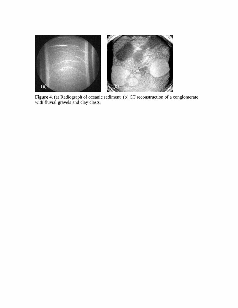
Figure 4. (a) Radiograph of oceanic sediment (b) CT reconstruction of a conglomerate with fluvial gravels and clay clasts.
(a) (b)