
Satellite Communications System -...
40
Satellite Communications System Maria Leonora Guico Tcom 126 Lecture 13 Capacity Allocation Multiplexing Transponders Applications
Transcript of Satellite Communications System -...

Satellite Communications System
Maria Leonora Guico
Tcom 126 Lecture 13
Capacity Allocation
Multiplexing
Transponders
Applications

Capacity Allocation Strategies
Frequency division multiple access (FDMA)
Time division multiple access (TDMA)
Code division multiple access (CDMA)

Frequency-Division Multiplexing
Alternative uses of channels in point-to-point
configuration
1200 voice-frequency (VF) voice channels
One 50-Mbps data stream
16 channels of 1.544 Mbps each
400 channels of 64 kbps each
600 channels of 40 kbps each
One analog video signal
Six to nine digital video signals

Frequency-Division Multiple Access
Factors which limit the number of subchannels provided
within a satellite channel via FDMA
Thermal noise
Intermodulation noise
Crosstalk
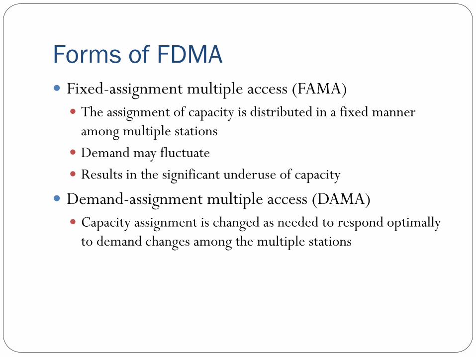
Forms of FDMA
Fixed-assignment multiple access (FAMA)
The assignment of capacity is distributed in a fixed manner
among multiple stations
Demand may fluctuate
Results in the significant underuse of capacity
Demand-assignment multiple access (DAMA)
Capacity assignment is changed as needed to respond optimally
to demand changes among the multiple stations

FAMA-FDMA
FAMA – logical links between stations are preassigned
FAMA – multiple stations access the satellite by using
different frequency bands
Uses considerable bandwidth

DAMA-FDMA Single channel per carrier (SCPC) – bandwidth divided
into individual VF channels Attractive for remote areas with few user stations near each site
Suffers from inefficiency of fixed assignment
DAMA – set of subchannels in a channel is treated as a pool of available links For full-duplex between two earth stations, a pair of
subchannels is dynamically assigned on demand
Demand assignment performed in a distributed fashion by earth station

Reasons for Increasing Use of TDM
Techniques
Cost of digital components continues to drop
Advantages of digital components
Use of error correction
Increased efficiency of TDM
Lack of intermodulation noise

FAMA-TDMA Operation Transmission in the form of repetitive sequence of
frames Each frame is divided into a number of time slots
Each slot is dedicated to a particular transmitter
Earth stations take turns using uplink channel Sends data in assigned time slot
Satellite repeats incoming transmissions Broadcast to all stations
Stations must know which slot to use for transmission and which to use for reception

FAMA-TDMA Uplink

FAMA-TDMA Downlink

Satellite
Satellite payload are several repeaters, known as transponders
mounted on platform called bus containing solar cells for
power, telemetry and control systems, and small jets to
slightly adjust orbit (station-keeping)

Transponder Types Signals are received at one freq, amplified and moved to
another frequency for retransmission
Transponder is basically a linear amplifier and frequency translator
Usable with analog and digital signals)
Transponder Block Diagram (C-band)

Regenerative Repeater
Used for purely digital signals
Demodulate signal to baseband, decode the digital
information, then remodulate the signal on a carrier with a
different frequency
Allows the satellite repeater to regenerate the signal while
removing accumulated noise and distortion

Frequency Allocation

Earth station
Baseband in
FDM or
PCM/TDM
Modulator
(FM, PSK or
QAM)
Mixer Band pass
filter
(BPF)
High Power
Amplifier
(HPA)
Generator
Up-Converter
Tel
Data Video
To
Satellite
transponder
AN EARTH STATION TRANSMITTER
Low noise
Amplifier
(LNA)
Demodulator
(FM, PSK
or QAM
Mixer Band pass
filter
(BPF)
Generator
Down-Converter
Baseband out
(FDM or
PCM/TDM) Tel
Data Video
From satellite
transponder
AN EARTH STATION RECEIVER

Earth station transmitter
Baseband in
FDM or
PCM/TDM
Modulator
(FM, PSK or
QAM)
Mixer Band pass
filter
(BPF)
High Power
Amplifier
(HPA)
Generator
Up-Converter
Tel
Data Video
To
Satellite
transponder
AN EARTH STATION TRANSMITTER
- Intermediate freq (IF) modulator converts the input baseband signals
to either an FM, a PSK or a QAM modulated intermediate frequency.
- The up converter converts the IF to an appropriate RF carrier freq.
- The High Power Amplifier (HPA) provides the adequate input
sensitivity and output power to propagate the signal to the satellite
transponder.

Earth station receiver
Low noise
Amplifier
(LNA)
Demodulator
(FM, PSK
or QAM
Mixer Band pass
filter
(BPF)
Generator
Down-Converter
Baseband out
(FDM or
PCM/TDM) Tel
Data
Video
From satellite
transponder AN EARTH STATION RECEIVER
- LNA which is highly sensitive and low-noise device amplifiers
the received signal.
- The RF to IF down-converter is a mixer and bans pass filter
combination, which converts the received RF signal to an
intermediate frequency (IF)

Transmission Modes
Beam switching – output from a transponder can be switched
to any one of several antennas (applicable to digital signals,
can use TDM)
Cross-links (operate at 58-62 GHz range)
Transmit signals directly between satellites
Allow signals to be transmitted to areas outside the coverage
area of one satellite, w/o using an extra earth station in
between

Application of satellite communication
Some of the application s of satellite communications are:
Digital audio broadcasting
Television distribution
Serving remote areas
Point-to-multipoint communications
Remote monitoring and control
Vehicle tracking
Mobile communications
Maritime and air navigation
Video teleconferencing

Applications of Geostationary
Satellites
Television and radio broadcasting
Telephony
Data transmission

Television and Radio Broadcasting
Carry network program feeds
Transmit pay-TV and other cable-only channels to CATV
company head-ends
Transmit remote news feeds
Radio broadcasts are carried, usually as subcarriers on
the same transponders
Typically uses analog FM modulation
Direct-to-home TV system transmits digital video ( 3 to
7.5 Mb/s data transmission rate)

Telephony via Satellite
Not ideal because of time delay
Used for remote areas where it’s too costly to install cable or
microwave relays
Important for ships at sea and interoceanic communications
where connection is via Inmarsat satellites
Uses FDMA-FM and SCPC

Data via Satellite Large data users can lease a transponder or a part of a transponder
for a point-to-point or point-to-multipoint link
Data network with a central hub communicating with many remote sites
Remote sites use very small aperture satellites (VSATs) which are low-cost installations with small antennas (1.2 to 2.4 m) and low-power transmitters
Hub uses relatively expensive earth station with large antenna (5 to 7 m) and powerful transmitter
Typical applications are inventory control, point-of-sale, and banking

Mobile Telephone Systems Using
Geostationary Satellites Global coverage achieved with only 3 GEO satellites
INMARSAT (International Maritime Satellite Organization) Original mandate was to provide voice and data service to ships
at sea; services have expanded to include land and aeronautical mobile communication
Refer to http://www.alphatelecom.ru/inmarsat/engindex.htm
for the different Inmarsat standards and corresponding services

INMARSAT Total of eleven GEO
satellites controlled from the HQ in London via ground stations located around the globe.
Each satellite has: hemispherical beam
and spot beams Maximum EIRP of 48
dBW in spot beams Power and BW
dynamically allocated L-band (1.5/1.6 GHz)
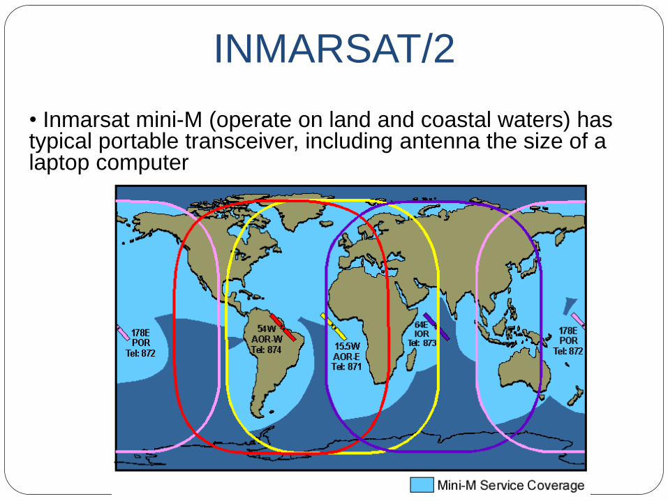
• Inmarsat mini-M (operate on land and coastal waters) has typical portable transceiver, including antenna the size of a laptop computer
INMARSAT/2

MSAT (Mobile Satellite) Joint Canadian and US project that uses one GEO satellite to
provide coverage for North and Central America, the Caribbean and Hawaii (via spot beam), and surrounding coastal waters
About 10 times more powerful than those used by Inmarsat
EIRP of at least 57.3 dBW in coverage area
Mobile terminals use reasonably compact roof-mounted antenna; portable terminals about the size of notebook computer with lid-mounted antenna
Only one ground station with an 11 m dish antenna

LEO Satellites
Preferred when satellites are used with portable or mobile equipment (lower transmitter power and antenna gain)
Requires many satellites (40 to 70) and a complex network
Main problems with LEOs are: 1. Position in space is not fixed wrt ground station 2. Tendency to disappear below the horizon – use a constellation of
satellites to address problem 3. Doppler effect (transmitted freqs are shifted higher as satellite
approaches a point on the ground and lower as the satellite recedes) – requires careful receiver design

LEO Satellites/2
Most complex and expensive wireless communication
systems
One system (Iridium) went bankrupt after going into service
As of April 2001, two LEO wireless telephony systems
(Iridium and Globalstar) were operating; both were in
financial difficulty

Iridium
66 Iridium LEO satellites provide 100% Global Coverage except
Hungary, Poland, N. Korea and N. Sri Lanka
Satellites are cross-linked
Uses digital modulation, FDMA/TDMA

Globalstar
Globalstar constellation consists of 48 LEO satellites, with an additional four satellites in orbit as spares, and operates at an altitude of 876 miles (1414 km) in space
CDMA; utilizes soft handoff techniques
Designed to provide high quality satellite-based services to a broad range of users, including: · Voice calling · Short Messaging Service (SMS) · Roaming · Positioning · Facsimile · Data transmission
http://www.alphatelecom.ru/globalstar/engindex.htm

Little LEOs
ORBCOMM
Operational in 1988; 35 LEO satellites as of Feb 2001; used for
SMS, email, and vehicle tracking
LEO One
Designed to use 48 satellites for paging and SMS
E-Sat
Designed to use 6 satellites using CDMA for remote meter
reading

MEOs
More satellites are needed than for GEO (on the order of 6
to 20 for real time communication) but fewer than for LEO
Delay and propagation loss lesser than for GEO
Main advantage over LEOs is financial

ICO
One MEO satellite launched in June 2001, referred to as "F2," which currently provides data gathering services for an agency of the U.S. government
Next-generation mobile satellite services (MSS) operator
Building a hybrid system to offer satellite and terrestrial wireless services throughout the US
ICO’s network is being designed to provide wireless voice, data, video, and/or Internet service throughout the United States on mobile and portable devices.

Ellipso Uses an interesting combination of elliptical and circular orbits.
Designed to initially include 6 satellites, later increasing to 10, in a circular orbit about 8000 km above the equator for worldwide coverage and to be complemented by 8 active satellites (plus two spares) in inclined elliptical orbits ( 520-7800 km)
CDMA technology; voice communication using portable and mobile terminals

Advantages/disadvantages of satellite
system Advantages of a satellite system include:
It can access to wide geographical area
Wide bandwidth
High reliability
Distance sensitive cost
Independent of terrestrial infrastructure
Disadvantages of satellite system
High initial cost
It has propagation delay
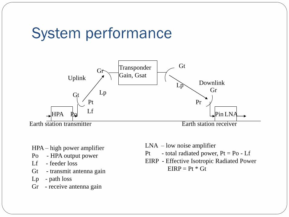
System performance
Transponder
Gain, Gsat
HPA LNA
Uplink Downlink
Gr Gt
Lp Lp
Pr
Gr Gt
Lf
Pt
Po Pin
Earth station transmitter Earth station receiver
HPA – high power amplifier
Po - HPA output power
Lf - feeder loss
Gt - transmit antenna gain
Lp - path loss
Gr - receive antenna gain
LNA – low noise amplifier
Pt - total radiated power, Pt = Po - Lf
EIRP - Effective Isotropic Radiated Power
EIRP = Pt * Gt

Link-Power Budget Formula
Link-power budget calculations take into account all the gains and losses from the transmitter, through the medium to the receiver in a telecommunication system. Also taken into the account are the attenuation of the transmitted signal due to propagation and the loss or gain due to the antenna.
The decibel equation for the received power is: [PR] = [EIRP] + [GR] - [LOSSES]
Where:
[PR] = received power in dBW
[EIRP] = equivalent isotropic radiated power in dBW
[GR] = receiver antenna gain in dB
[LOSSES] = total link loss in dB

Link-Power Budget Formula Variables
Link-Power Budget Formula for the received power [PR]:
[PR] = [EIRP] + [GR] - [LOSSES]
The equivalent isotropic radiated power [EIRP] is:
[EIRP] = [PS] + [G] dBW, where:
[PS] is the transmit power in dBW and [G] is the transmitting antenna gain in dB.
[GR] is the receiver antenna gain in dB.
[LOSSES] = [FSL] + [RFL] + [AML] + [AA] + [PL], where:
[FSL] = free-space spreading loss in dB = PT/PR (in watts)
[RFL] = receiver feeder loss in dB
[AML] = antenna misalignment loss in dB
[AA] = atmospheric absorption loss in dB
[PL] = polarisation mismatch loss in dB
The major source of loss in any ground-satellite link is the free-space spreading loss.


![[Injection Moulding Calculations] - xa.yimg.comxa.yimg.com/kq/groups/23535563/538311540/name/IMM_Calculator.pdf · [Injection Moulding Calculations] It’s SADANANDA’s Page 1 Table](https://static.fdocuments.in/doc/165x107/5a9d94227f8b9a28388be559/injection-moulding-calculations-xayimgcomxayimgcomkqgroups23535563538311540nameimm.jpg)


![[XLS]xa.yimg.comxa.yimg.com/kq/groups/14723179/1229839518/name/PINCODES.xls · Web viewSuriyur ; Palanganangudi ; Hapf Township ; 620026 Annanagar Annanagar ; 620101 Muthrasanallur](https://static.fdocuments.in/doc/165x107/5ab11d927f8b9a7e1d8bfe36/xlsxayimgcomxayimgcomkqgroups147231791229839518name-viewsuriyur-palanganangudi.jpg)


