SATELLITE APPLICATIONS OF THE BIFILAR HELIX ANTENNA · SATELLITE APPLICATIONS OF THE BIFILAR HELIX...
6
ROBERT K. STILWELL SATELLITE APPLICATIONS OF THE BIFILAR HELIX ANTENNA The performance of the antenna system can be crucial to the success of some satellite applications. A low Earth orbiter requires a broad beam width and should maximize the gain in the direction of maximum path loss. The backfire bifilar helix is a simple antenna that is well suited to this need. The operation of the helix is described, simple methods of feeding and impedance matching are recommended, and design examples are given. INTRODUCTION An important component of a satellite RF communica- tions system is the spacecraft antenna. The directive gain of the antenna can determine how much transmitter pow- er is required to support a given data rate, which is often set by mission requirements. For some applications, such as those involving imaging instruments, the rate may be quite high. The RF power, however, is somewhat expen- sive in the sen e that 5 or 6 W of DC power is required for each watt of transmitter power. High-power transmitters can also have adverse effects on the thermal control sys- tem and may cau e concerns about reliability. An antenna can be characterized by its "gain," which i a function of direction. Antenna gain is defined as 471'" time the power radiated per unit solid angle, divided by the total power delivered to the antenna. A hypothetical antenna that i los less and radiates equally well in all directions (known as an i otropic antenna) would there- fore have a gain of 1 everywhere. Conservation of energy indicates that increased ga in in one direction can be ob- tained only at the expense of decreased gain in another direction. The goal in antenna design is to radiate power efficiently in the desired directions and to avoid wasting power by suppressing the radiation in unwanted direc- tion s. De spite the importance of antenna gain, a good sys- tem design must take into consideration not only the electrical performance of the antenna system but also its interactions with other spacecraft systems and the mis- sion itse lf, particularly weight, volume, field-of-view re- quirements, cost, complexity, and reliability. The trade- offs can be seen in the differences in antennas flown on different type, of satellites. Communications satellites often have large, high-gain, mechanically steered anten- nas. Conversely, the antennas used on cientific satellites are generall y smaller and mechanicaIly fixed but must stiIl afford the best electrical perfOImance commensurate with those constraints. The latter category of antennas is di scussed in this article. We begin by considering the requirements placed on the antenna of a satellite that is in low Earth orbit and Jo hns Hopkins APL Technical Digest, loillme 12, NllmiJer I (/991) has an "Ea rth-oriented" tabilization system, a combina- tion frequently encountered. The optimum characteris- tics for a fixed antenna are derived, and the types of an- tennas used in practice and the degree to which they achieve those optimum characteristics are discussed. The backfire bifilar helix antenna is then addres ed in detail. Its electrical operation and a feeding and matching tech- nique that was developed at APL are described. Design examples that have flown on several APL satellites are presented, and promising experimental work on higher- performance variations of the antenna is discussed. ANTENNAS FOR LOW EARTH- ORBITING SATELLITES The geometry of a low Earth-orbiting satellite is shown in Figure 1. Many such satellites (for example, those involved in remote sensing of the Earth) use an Earth-oriented stabilization system, which keeps one ax- is of the spacecraft aligned with the local vertical. During a pass over a ground station, the line of sight from the satellite to the ground antenna changes continually rela- tive to the satellite coordinate system. If the satellite has a high-gain, nalTow-beam antenna, a positioner must be used to keep it pointed in the correct direction. The cost, complexity, weight, and reliability concerns associated with positioners are generally avoided by using a fixed antenna with a wide enough beam width to maintain Figure 1. Geometry of a low Earth-orbiting satellite, showing the variation in slant range . 75
Transcript of SATELLITE APPLICATIONS OF THE BIFILAR HELIX ANTENNA · SATELLITE APPLICATIONS OF THE BIFILAR HELIX...
ROBERT K. STILWELL
SATELLITE APPLICATIONS OF THE BIFILAR HELIX ANTENNA
The performance of the antenna system can be crucial to the success of some satellite applications. A low Earth orbiter requires a broad beam width and should maximize the gain in the direction of maximum path loss . The backfire bifilar helix is a simple antenna that is well suited to this need. The operation of the helix is described, simple methods of feeding and impedance matching are recommended, and design examples are given.
INTRODUCTION
An important component of a satellite RF communications system is the spacecraft antenna. The directive gain of the antenna can determine how much transmitter power is required to support a given data rate, which is often set by mission requirements. For some applications, such as those involving imaging instruments , the rate may be quite high. The RF power, however, is somewhat expensive in the sen e that 5 or 6 W of DC power is required for each watt of transmitter power. High-power transmitters can also have adverse effects on the thermal control system and may cau e concerns about reliability.
An antenna can be characterized by its "gain," which i a function of direction. Antenna gain is defined as 471'" time the power radiated per unit solid angle, divided by the total power delivered to the antenna. A hypothetical antenna that i los less and radiates equally well in all directions (known as an i otropic antenna) would therefore have a gain of 1 everywhere. Conservation of energy indicates that increased gain in one direction can be obtained only at the expense of decreased gain in another direction. The goal in antenna design is to radiate power efficiently in the desired directions and to avoid wasting power by suppressing the radiation in unwanted directions.
Despite the importance of antenna gain, a good system design must take into consideration not only the electrical performance of the antenna system but also its interactions with other spacecraft systems and the mission itself, particularly weight, volume, field-of-view requirements , cost, complexity, and reliability. The tradeoffs can be seen in the differences in antennas flown on different type, of satellites. Communications satellites often have large, high-gain , mechanically steered antennas. Conversely, the antennas used on cientific satellites are generall y smaller and mechanicaIly fixed but must stiIl afford the best electrical perfOImance commensurate with those constraints. The latter category of antennas is di scussed in this article.
We begin by considering the requirements placed on the antenna of a satellite that is in low Earth orbit and
Johns Hopkins A PL Technical Digest, l o illme 12, N llmiJer I (/991)
has an "Earth-oriented" tabilization system, a combination frequently encountered. The optimum characteristics for a fixed antenna are derived, and the types of antennas used in practice and the degree to which they achieve those optimum characteristics are discussed. The backfire bifilar helix antenna is then addres ed in detail. Its electrical operation and a feeding and matching technique that was developed at APL are described. Design examples that have flown on several APL satellites are presented, and promising experimental work on higherperformance variations of the antenna is discussed.
ANTENNAS FOR LOW EARTHORBITING SATELLITES
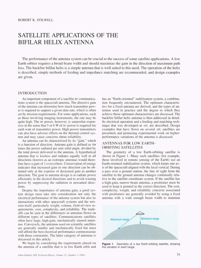
The geometry of a low Earth-orbiting satellite is shown in Figure 1. Many such satellites (for example, those involved in remote sensing of the Earth) use an Earth-oriented stabilization system, which keeps one axis of the spacecraft aligned with the local vertical. During a pass over a ground station, the line of sight from the satellite to the ground antenna changes continually relative to the satellite coordinate system. If the satellite has a high-gain , nalTow-beam antenna, a positioner must be used to keep it pointed in the correct direction. The cost, complexity, weight, and reliability concerns associated with positioners are generally avoided by using a fixed antenna with a wide enough beam width to maintain
Figure 1. Geometry of a low Earth-orbiting satellite, showing the variation in slant range .
75

R. K. Stilwell
communications over an entire pass. Circular polarization ensures that the rotation angle of the antenna around the line of sight is unimportant.
The slant range to an Earth station directly below the satellite is much less than when the station is near the edge of the satellite 's field of view. For a spacecraft in an 800-km orbit , the Earth subtends a full angle of 125 o.
The variation in path loss as a function of the angle at the satellite is shown in Figure 2. The curve can be thought of as a path-loss compensation requirement. l The angle corresponding to the direction of the maximum slant range can be considered the "critical angle." An efficient antenna system should maximize the gain at the critical angle but not let it fall below the path-loss compensation curve at smaller angles. Power radiated in directions that do not intercept the Earth is wasted, and the gain in those directions should be minimized. The ideal antenna therefore is circularly polarized, lossless , and has a radiation pattern shaped like the curve in Figure 2.
Ideal antenna performance can be approximated to varying degrees of accuracy. The field of view of 125 0 is rather large, and many common antennas have beam widths much too narrow to cover such a wide angle effectively ; therefore, the first step in improving antenna performance is to produce a wide beam with circular polarization. The fractional-turn resonant quadrifilar helix was developed at APL for this application and has been widely used.2 Typically, a gain of isotropic (the gain of a hypothetical , lossless isotropic antenna) or slightly greater can be achieved at the critical angle, but the peak gain is on boresight, and significant power is radiated at angles outside the field of view.
Better performance can be obtained from a longer, multiple-turn, resonant quadrifilar helix that radiates a conical beam.3 The gain decreases more rapidly outside the field of view, and the peak gain, generally about +3 dBic (decibels referenced to an isotropic circular antenna) , is now directed at the critical angle. A canted turnstile over a ground plane, an alternative type of antenna, can yield comparable results. A custom-designed antenna using a large, specially shaped reflector gives the best performance; a gain greater than +8 dBic at the critical angle has been reported.4 But such a device scaled to the S-band telemetry frequency would be about seven feet in diameter-too large for most satellites. Moderate performance from a reasonably sized antenna is a better system compromise.
THE BACKFIRE BIFILAR HELIX ANTENNA
Another type of antenna that is applicable to low Earth-orbiting spacecraft with Earth-oriented stabilization systems is the backfire bifilar helix. Its advantages include high efficiency, a convenient size at S band, and extreme simplicity that results in high reliability. A relatively short antenna can be designed to produce circular polarization over a broad beam width. With a longer antenna, a conical beam can be generated that is a first approximation to the ideally shaped radiation pattern.
In its most basic form , the bifilar helix consists of two wire elements formed into a helical geometry and displaced by 180 0 around the cylindrical envelope of the he-
76
lix. One parameter of the helix is its radius; the other is the distance between successive turns of one of the wire elements, referred to as the "pitch distance." These dimensions are often normalized to the electrical wavelength in free space.
The operation of the bifilar helix as an antenna can be understood from the properties of the electromagnetic waves that propagate along such a helical structure. PattonS reported on this subject in some detail. With a proper choice of helical parameters, a fast backward wave can be supported. This type of wave is characterized by a phase velocity that is greater than the speed of light and will therefore radiate readily.6 On the other hand, the group velocity (which is indicative of the energy flow) is, of course, slower than the speed of light and is in a direction opposite to that of the phase velocity. The general characteristics of such backward waves are discussed in Ref. 7. The wave of interest on the bifilar helix is a balanced mode; that is, currents on the wires are equal in amplitude but opposite in direction.
These basic properties can be exploited to produce a novel antenna; an example is shown in Figure 3. A balun (a device to match a balanced transmission circuit to an
0
CD -2
~ (/J -4 (/J
.Q J:: ~ -6 a. Q) > .~ -{3 Q) ex:
-10
-12
-70 -50 -30 -10 10 30 Angle from local vertical (deg)
Figure 2. Path loss versus angle at the satellite.
50 70
Infinite balun feed arragement
Copper tape trimmed for impedance matching
Dummy coaxial cable
Group velocity (energy 1 transport) away from
the feed
Direction of maximum " radiation, a cone
about the helix axis
Wave attenuated because of radiation. [
Lower portion of the helix is not critical. 't /-',,....-.................
Feed coaxial cable
t Fast phase velocity I toward feedpoint
Shorting bar
Feed cable
Figure 3. The backfire bifilar helix antenna.
Johns Hopkins APL Tee/lIlical Digest, Vollll1le 12, Number I (199 1)

HELICAL ANTENNAS-TYPES AND NOMENCLATURE
Although several types of helical antennas exist, they can be distinguished by the following criteria.
Number of Wire Elements
Consider a simple helix with only one wire element; an example is an ordinary spring. Thi configuration is sometimes known as a unifilar helix. If two such springs are intermeshed with their center line coincident, a bifilar helix tructure is obtained. A symmetrical geometry is generally
used: one spring is rotated 1800
from the other. An extenion of this concept to four springs, with 90
0 eparation be
tween the elements, results in a quadrifilar helix.
Method of Feeding the Helix
An antenna is generally fed from a coaxial transmission line, which has equal and opposite cun·ents flowing on its inner and outer conductors. A unifilar helix is usually connected to the center conductor of the coaxial cable, and the current on the helix at that point is equal to the current on the inner conductor. The opposing current on the outer conductor flows radially onto a ground plane that is electrically connected to that conductor. Therefore, the unifilar helix is sometimes said to be "fed against a ground plane. " A bifilar helix, on the other hand, is excited with equal and opposite currents on the two wires, so no ground plane is involved. As mentioned in the text, however, a balun is required to achieve balanced potential. The quadrifilar helix is usually fed so that the currents on the four elements have a 90
0
electrical phase progression. Again, no ground plane is required , but a feed network is necessary to supply the correct phasing.
unbalanced transmission line such as normal coaxial cable) is used to excite the desired balanced wave from one end of a helix. The energy propagates along the structure but has a fast phase velocity in the opposite direction, toward the feed. The radiation is therefore in the same general direction , and this property is responsible for the term "backfire." The direction of maximum radiation intensity is at an acute angle to the axis of the helix , and symmetry around this axis is maintained. The radiation pattern can be thought of as a broad conical beam. The polarization is predominantly circular, with a right-hand helical thread yielding left-hand circular polarization. The loss of energy because of radiation attenuates the wave as it travels along the helix. If the helix is long enough, the two windings can simply be shorted together at the end opposite the feed , without significant effect on the radiation characteristics. The antenna is not resonant in nature and therefore has the potential of maintaining a constant input impedance over a fairly broad bandwidth. A ground plane is not required, making the antenna attractive for satellite applications.
PattonS analyzed the radiation characteristics of a range of helical geometries and presented measured data for comparison. More recently, Nakan08 applied numerical modeling techniques to thi s class of antenna. Limited
Johns Hopkills APL Tecl1l1ical Digest , \folllme 12, Nllmber I (1991 )
Satellite Applications of the Bi/i/a,. Helix Antenna
Traveling-Wave or Standing-Wave Currents
The current distribution on a wire element of a resonant quadrifilar helix is nearly sinusoidal; that is, it has the form of a standing wave. On other helice , such as the bifilar antennas described in the text, the distribution is more nearly a traveling wave, which in that case is also attenuated as it proceeds away from the feed. The standing-wave characteristic of the current on the quadrifilar helix causes the input impedance to be critically dependent on the length of the elements, and so a good impedance match can be maintained only over a narrow frequency band. This characteristic is responsible for the descriptive term "resonant." Helices with traveling-wave current distributions generally have a larger bandwidth.
Endfire or Backfire
Consider a rectangular coordinate system fixed to a helix with the feed end of the helix at the origin and the axis of the helix extending along the +x axis. If the direction of the peak radiation is in the +x direction, the antenna is said to be "endfire." If the maximum radiation is more nearly in the -x direction, the term is "backfire. "
Broad or Narrow Beam
One very common type of helical antenna is unifilar. It is fed against a ground plane, has a traveling-wave current distribution , is endfire, and usually has many turns. This axial mode helix produces a narrow beam with high directivity. Conversely, the resonant quadrifilar helices and backfire bifilar helices described in the text are intentionally designed to radiate broad beams, sometimes conical in shape.
experimental data have also been collected at APL. Some general trends relating the radiation characteristics of a helix to its geometry can be identified from these sources. For instance, as the frequency is increased, the peak of the conical beam scans away from the axis of the helix. This characteristic may limit the usable bandwidth in some applications. The attenuation of the wave along the helix is less rapid for smaller-diameter helices, which means that thin antennas must be made longer to avoid reflections from the shorted windings and that the produced beam is narrower because of the longer active length. For helices of constant diameter, an increase in the pitch distance tends to increase the scan angle of the beam. If the helical elements are wound on a dielectric tube for mechanical support, perturbations in the shape of the radiation pattern can result. The geometry of the helix can usually be adjusted to compensate for such effects.
FEED CONSIDERATIONS The backfire bifilar helices that have been developed
at APL use techniques that result in remarkably simple antennas. The development of these techniques can be traced to a program, then known as the Global Positioning System-Sonobuoy Missile Impact Location System,
77

R. K. Stilwell
that needed an inexpensive Earth-based antenna to receive signals from the Global Positioning System. Although other type of antenna , such as the resonant quadrifilar heli x,2 could easily have supplied the required performance, it was felt that they would be too expen ive because of the need for balun and quadrature hybrids to feed the antenna and the possible need for individual tailoring to ensure re onance at the proper frequency. The bifilar helix antenna was then investigated because it is not resonant it hould be tolerant of dimensional inaccuracie , it need no quadrature hybrid, and a very impie technique can be u ed to achieve a balanced feed.
Balanced-mode excitation of a bifilar helix can be achieved with an infinite balun.9 Coaxial cable are used for the wire elements of the helix, and the signal is sent up the inside of one of the cables to the feed point. The center conductor of that coaxial cable is then electrically connected to the outer conductor of the other coaxial cable, which is sometimes known as a "dummy" because its center conductor is not u ed. This alTangement results in equal and opposite current on the outside of the two cables. The technique ha been called the 'infinite balun" because only con truction inaccuracies prevent the method from working over an infinite-frequency bandwidth. If the helix i long enough to ensure sufficient attenuation of the current excited on the outer surfaces of the coaxial shields, the configuration of the cables at the termination of the helix i not important. The shields are usually shorted together at that point. Since the bifilar helix is not resonant in nature, the exact length of the coaxial elements i not critical, and no tailoring i required.
Early developmental work with helices constructed by using the infinite-balun technique revealed a seriou problem. For the helical geometries under investigation , the input impedance of the antennas was severely mi -matched to the 50-D system impedance generally in u e. Voltage standing wave ratios in excess of 10: I were not uncommon. Conventional matching techniques such a impedance tran formers or stubs could be used, but they would have to be placed at the end of a feed cable, which must be rather long since it i also a helical antenna element. The exact line length would be critical, and only a narrowband match could be expected. The infinite-balun technique and the input impedance of the bifilar helix did not seem to be compatible.
A simple olution to the matching problem was inspired by a technique for axial-mode helices reported by Kraus. lo Planar conductors, u ually pie-shaped, are 01-dered to the radial portion of the elements at the feed region. By empirically adjusting the size and position of these pieces, a good impedance match can be obtained with the large-radius helical geometries that produce broad beam width radiation patterns. I I Symmetry with respect to the two helical element must be maintained to en ure a balanced excitation of the antenna. The technique has been found to be repeatable, and impedance bandwidth of 30% typically are achieved. No significant effect on the radiation pattern have been observed. Smaller-diameter helices, such as those used for beam haping, may not have enough area available for the sim-
78
pie pie-shaped pieces to produce a good match. Additional area can be obtained by continuing the conductors to include a mall p0l1ion of the cylindrical sUIface of the helix (Fig. 3). Extending the planar conductors past the radius of the helix can also produce a match, but the radiation pattern of the antenna may then be severely degraded.
EXAMPLES
A simple broad-beam backfire bifilar helix wa de igned as the S-band telemetry downlink antenna for the Geosat, a radar altimeter atellite. Grooves were machined into a 1.343-in.-oD fiberglass tube to create a form for the three-turn helix. Coaxial cable (RG-3 16) was wrapped into the groove at a pitch distance of 1.75 in., and the infinite-balun feed technique was used. Care was taken to prevent a tight bend in the coaxial cable at the transition between the helical and radial portions of the elements. The pie-shaped matching pieces were etched from a copper-clad fibergla s disk. The geometry for the matching disk was established on an electrical model antenna, and no individual tailoring of these pieces was required on the subsequent flight hardware. The entire feed region of each antenna was potted with structural epoxy, and slight variations in the quantity of epoxy were used to fine-tune the individual antennas. The antennas were mounted on the ends of drooping olar panels; therefore, angle brackets were de igned to point the antennas correctly. In turn , a connector bracket was located on the mounting bracket. The fiberglas tube and the mounting hardware fOlmed the antenna a embly shown in Figure 4. White paint was used as a thermal control surface.
Three antenna were produced for Geosat: two flight a semblies and one flight pare. The voltage standing wave ratio was kept below 1.3: 1 on all units. A gain of at lea t 0 dBic wa easily maintained for angles out to 62 0
from the helix axis . In addition, the gain exceeded -8 dBic over a full hemisphere. A sample antenna pattern is hown in Figure 5. Flight-qualification vibration and
thermal-vacuum testing was completed without incident. Geosat was launched on 12 March 1985 and has succes -fully completed it five-year mis ion.
Another bifilar heli x wa flown in support of a mis-ion that did not require full coverage of the visible
Earth. A pattern having a narrower beam and a somewhat higher gain was de ired to e tabli h the link for portion of the Earth near nadir. The con truction technique u ed in thi s antenna are imilar to tho e of the Geosat te-
Figure 4. The S-band telemetry antenna for the Geosat satellite.
Johlls Hopkills APL Techllical Digest, 1'DllIIlle 12, limber 1 (1991 )

lemetry antennas. The frequency of operation is significantly lower, so the antenna is physically larger, and a deployment mechanism was required. A four-turn de ign was adopted, and a boresight gain of +5 dBic was achjeved along with gain exceeding +3 dBic out to 45 o. This antenna, which was painted black for thennal control, is shown in Figure 6. A typical pattern is shown in Figure 7. Again, full flight-qualification vibration and thermal-vacuum testing was easily passed.
The wide, symmetrical beam produced by a bifilar helix makes it attractive as a primary feed for a parabolic reflector antenna. An example was produced to support in-orbit commurucations at S band (2374.5 MHz) and C band (5765 MHz) for the Delta 18] mission. Packaging constraints limited the reflector diameter to ] 3 in. A modified crossed-dipole feed was developed to utilize this small dish at S band. Since it was located at the vertex , the focus was left free for the C-band feed, which consisted of a small backfire bifilar helix that was constructed by using techniques similar to tho e de cribed previously. Three turns of a small RG- 178 coaxial cable on a 0.375-in.-OD fiberglass tube and an etched matching disk were used. The small size prevented excessive aperture blockage, and illumination with a 14-dB edge taper was obtained. A boresight gain of 24 dBic and a 3-dB beam width of 9.5 ° were measured. An aperture efficiency of 63% i therefore indicated. The completed antenna assembly is shown in Figure 8.
No flight experience has been accumulated on true shaped-beam bifilar helix antennas, but some promising experimental work has been performed in conjunction with an independent research and development project. A phenolic tube with an OD of l.25 in. and a wall thickness of 0.094 in. was used as a form for the helix. (Subsequent work has indicated that thi s material is a rather poor dielectric and that its use in thi application can result in undue loss.) The helical elements were formed from RG-316 coaxial cable by u ing four turns with a pitch
1800
Figure 5. Typical radiation pattern of the Geosat S-band telemetry antenna.
10hns Hopkins APL Technical Digesl, \loillme 12, Nllmber 1 ( 1991)
Sate/lite Applications of the Bift/ar Helix Antenna
distance of 4.0 in. At a frequency of ] 375 MHz, an attractively shaped beam was produced. The matching element had to be extended to include part of the cylindrical surface, as discussed previously. Figure 9 shows a typical radiation pattern and the curve of path-loss compensation. A gain of +3 dBic was measured at the critical angle of 62 o. This preliminary work indicates that despite the suspected dielectric loss, a simple bifilar antenna can achieve shaped-beam performance at least as good a that obtained from the more complex multipleturn resonant quadrifilar helix.1 2 Figure 10 is a photograph of the experimental antenna.
Figure 6. The bifilar helix antenna with a narrower beam.
Figure 7. The radiation pattern of the antenna shown in Figure 6 (isotropic 12.2 dB on chart).
79

R. K. Stilwell
Figure 8. The bifilar helix used as a feed for a parabolic reflector antenna.
CONCLUSION
System constraint often require that a fixed antenna be used for the communication links of a scientific satellite. The performance of the antenna can be crucial to the RF system. For a low Earth orbiter with an Earth-oriented stabilization y tern, the optimum antenna radiation pattern is relatively broad and concentrate the gain at the edges of the beam. The optimum pattern can only be approximated, ince the be t approximation require very large antennas. A good compromi e between performance and size is the backfire bifilar helix, a imple and efficient antenna that has proved it elf on everal APL
satellites.
REFERENCES
I Ricardi. L. J .. "Satellite Antennas:' in Allfelll/o Ellgilleerillg Halldbook. 2nd Ed .. John on. R. c.. and Ja, ik. H. (eds.) . McGraw-Hill. ew York. pp. 35-1 to 35-13 ( 1984).
1 Kilgus. C. c.. "Resonant Quadrifilar Helix Design:' Micrmrm'e J . 13.49-5.+ (Dec 1970).
3 Kil gus. C. c.. "Shaped-Coni cal Radiation Panern Perfo llllance of the Backfire Quadrifilar Helix:' IEEE Trails. Allfelllws Propag. AP-23 . 392-397 (1975) .
.. Moskowitz. S. (ed.). "Shaped- Beam Antenna Spreads niform Signal Over the Earth:' Microl\·l/I'es. 10- 11 (Mar 1979).
5 Patton. W. T.. The Backfire Bijilar Heliced Allfellllo. Antenna Laboratory technical report 10 . 61. Electrical Engineering Re earch Laboratory Engineering Expeliment Station. niver ity of lliino i ·. rbana (Sep 1962).
6 Walter. C. H .. TrC/l'elillg \\I(fI'e Allfellllos. McGraw-Hill. ew York. pp. 349-351 ( 1965 ).
7 Ramo. S .. Whinnery. J. R .. and Van Duzer. T .. Fields (llId WC/\'es ill COlllllllll1icafioll Elecfrollics. John Wil ey and Sons. ew York. pp. 48-53 ( 1965 ).
8 akano. H .. Helical alld Spiral Amellllas-A IIl11erical Approach. Research Studies Press. Letch worth. England. pp. 17 1- 195 ( 1987).
9 DuHamel. R. H .. and Chadwick. G. G .. "Frequency- Independent Anten na :. in Amelllla Ellgilleerillg Halldhook. 2nd Ed .. Johnson. R. C .. and Jasik. H. (eds .). McGraw- Hill. New York. p. 1-1-9 ( 1984) .
10 Kraus. J . D .... A 50-Ohm Im pedance for He lica l Beam Antennas." IEEE TrailS. Allfellllas Prop Ig. AP-2S. 913 ( 1977).
II Webster. C. w.. and Stilwe ll. R. K .. Backfire Bifilar Helix Allfellllo . .S. Patent 4.608.57-+ (26 Aug 1986).
12 Bricker. R. W .. Jr .. "A Shaped Beam Anten na for Satellite Data Commun ication." in Pmc. IEEE Alllellnos alld Propagat ion Sy/lIp .. pp. 121 - 126 ( 1976).
80
Figure 9. Typical radiation pattern from an experimental shaped-beam bifilar helix antenna. The curve of path-loss compensation is shown.
Figure 10. The experimental shaped-beam bifilar helix antenna.
CK OWLEDGME T: The author gratefull y ack nowledges the contributi on of Car. on W. Webster. wh wa~ instrumental in the design and realization of the tlight antennas described in this LlI1ic le and who is a joint in ventor of the original techniques that made them possible.
THE AUTHOR
ROBE RT K. STILWELL received his B.S . degree in e lectri ca l e ng ineering from Kansas State Unive rs ity in 1973 and hi M.S . degree from The John Hopkin Univerity in 1976. Since joining APL
in 1973, he has been involved in the de ign. development. and testing of various type of antennas that have flo wn on more than twenty ate llite. He has also been concerned with ground-based antennas and has contri buted to numerous Space Department studies. Mr. Stilwell i an ass istant secti on upe rvi sor in the Comm unications,
RF, and Opt ica l Sy tems Group.
Johns Hopkins APL Technical Digesl, ]lolllllle 12, Nllmber I (1991)


![Design of Ionofree Micro Strip Quad Helix Antenna for ... · antenna, bifilar helices antenna, microstrip antenna, quadrafilar helix antenna. ... Helical antenna [1],[2] is broadband](https://static.fdocuments.in/doc/165x107/5b9506e809d3f2ea5c8b5a04/design-of-ionofree-micro-strip-quad-helix-antenna-for-antenna-bifilar-helices.jpg)