General standard for Hairpin -Type heat exchangers Third ...
Spectra-Mat, Inc. © 2014 Spectra-Mat, Inc.
Materials and Components for Electronics 100 Westgate Drive, Watsonville, CA 95076 – USA - Ph. +1.831 7224116 - Fax +1.831 7224172
www.spectramat.com
Introduction: Cathode designs from Vacuum Electron Device (VED) origi-
nal equipment manufacturers (OEMs) frequently come with
the drawing note, “Non inductive potted heater ” or “Heater
wire to be . . . wound in a noninductive configuration.”
Such requirements are generally qualitative and create a par-
adox whereby the cathode designer must select between
manufacturability and inductiveness. No ohmic heater is
completely non-inductive.
By their nature, heater coils with an internal current create
stray magnetic fields. When using an ac power supply, the
variation in these stray magnetic fields at or near the emitting
surface serves to periodically deflect emitted electrons, thus
imparting undesirable signals – “ripple” – on the electron
beam. The magnetic field by the emitting surface of the
cathode can be critical, with the field at the cathode cylinder
a secondary consideration. With the creation of a suitable
model, the field at various points along the cathode is calcu-
lable. Less frequently, direct measurements are made.
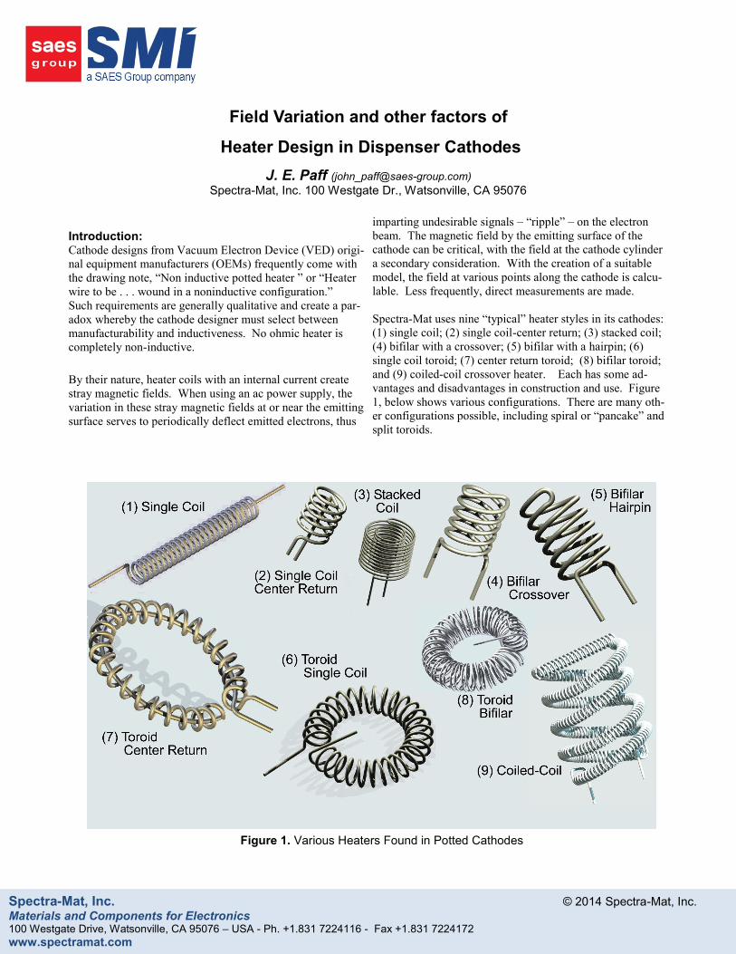
Spectra-Mat uses nine “typical” heater styles in its cathodes:
(1) single coil; (2) single coil-center return; (3) stacked coil;
(4) bifilar with a crossover; (5) bifilar with a hairpin; (6)
single coil toroid; (7) center return toroid; (8) bifilar toroid;
and (9) coiled-coil crossover heater. Each has some ad-
vantages and disadvantages in construction and use. Figure
1, below shows various configurations. There are many oth-
er configurations possible, including spiral or “pancake” and
split toroids.
Figure 1. Various Heaters Found in Potted Cathodes
Field Variation and other factors of
Heater Design in Dispenser Cathodes
J. E. Paff ([email protected])
Spectra-Mat, Inc. 100 Westgate Dr., Watsonville, CA 95076

Spectra-Mat, Inc. © 2014 Spectra-Mat, Inc.
Materials and Components for Electronics 100 Westgate Drive, Watsonville, CA 95076 – USA - Ph. +1.831 7224116 - Fax +1.831 7224172
www.spectramat.com
0
2
4
6
8
10
12
14
-0.2 -0.15 -0.1 -0.05 0 0.05 0.1 0.15 0.2
Position (inches) along Cathode (Bifilar Hairpin)
Ga
uss
CL
-5.0 -3.8 -2.5 -1.27 0.0 1.27 2.5 3.81 8.0
Position (mm) along Cathode (Bifilar Hairpin)
(1.27) (0.63)
.000
1.00 2.00
(mm)
Analyses:
To form a complete picture of the field variations determined
by the heater geometry, a model of each heater was created in
Field Precision’s Magnum FEA code.
The model consisted of a heater can, assumed to be
molybdenum, with a planar tungsten emitter. The field
calculation was made 2 mm above the top surface. The
tungsten emitter was assumed to be 1 mm (.040”) with a .25
mm (.010”) gap between the top of the heater and bottom of
the emitter. A separate calculation at the edge of the cathode
assumes a measurement at the cathode edge. See Figure 2.
Assumptions concerning the models are as follows:
• Constant wire length
• “Zero” diameter wire
• Constant current
• Planar emitting surface
• Constant.heater outer diameter
• Tungsten, molybdenum, alumina not paramagnetic.
No estimate of wire or cathode temperature was calculated.
Current input for each model was 2.0 A.
Figure 3 displays typical output. The bifilar hairpin model
under the emitter creates a large field at the wire surface, the
(–1.27) mm line on the chart. This is in the potting, at the
intersection of the wire and the potting, away from the
emitting surface. There is a spike and trough where the
heater loops back onto itself.
The five lines of Figure 3 represent different measurement
points. The two lines at (1.27 mm) and (.063 mm) are inside
the cathode potting. As we proceed further away from the
wire, at the emitting surface and then above the emitting
surface, the field sums to a more consistent level.
Emitter
.010” [.25 mm]
.040” .078” [2 mm]
Edge analysis
Figure 2: Emission surface to heater spacing
(Coiled-coil heater shown)
Figure 3: Field from bifilar hairpin heater

Spectra-Mat, Inc. © 2014 Spectra-Mat, Inc.
Materials and Components for Electronics 100 Westgate Drive, Watsonville, CA 95076 – USA - Ph. +1.831 7224116 - Fax +1.831 7224172
www.spectramat.com
At 2 mm away from the emission surface we have a relatively
flat field of approximately .5 gauss.
A comparison to a measured test part was performed. At
the center of a Ø.7.62 mm diameter cathode heater with a
coiled-coil heater potted in the back cavity, at a
measurement distance of 2 mm (approximately), the
measured field is 1.5 gauss. Our calculated value for the
same geometry is 1.7 gauss. The values, while not
perfectly aligned, are similar enough to allow an
expectation that the comparisons of the study are generally
representative of the heater types.
Figure 4 shows all of the fields for the heaters, measured at
2 mm away from the emission surface. Note that in Figure
4, the three lowest field heaters are barely visible, as they
are orders of magnitude lower in field than the heaters with
the highest field.
As the study is intended for a representative, qualitative
review, not absolutes, a more useful representation is to
choose one heater and compare the remaining units using
that as a baseline. From that chart, relative values can be
quickly ascertained to aid the designer. To create the
comparison chart the toroid heater was chosen as the
baseline heater, as it was roughly in the middle of the
group. A straight toroid such as the unit shown in Figure 5
has an moderate field — unlike the bifilars or the center
return units, there is no wire specifically arranged to
counterbalance the field in the primary coil.
Figure 6, then, is the same data as Figure 4, but plotted as a
ratio of the field of one specific heater over the field of the
toroid. To amplify the differences, the ratio is plotted on a
log scale. We see immediately that the center return toroid
and the bifilar toroid are (roughly) two orders of magnitude
lower than our baseline toroid, and that the single coils,
even with a center return, are six-fold higher in magnetic
0.0
1.0
2.0
3.0
4.0
5.0
6.0
7.0
-0.20 -0.15 -0.10 -0.05 0.00 0.05 0.10 0.15 0.20
gauss
Position (inches) along cathode
Sgl_Coil_FL
Sgl_Coil_Cr_FL
Stack_Coil_FL
Bifilar-FL (Hairpin)
Bifilar_XO
Toroid_FL
Toroid_CR_FL
Toroid_CR_NoLds
Toroid Bifilar
Coiled-Coil
Figure 4: Field of all heaters
Figure 5: Toroid heater
-5.0 -3.8 -2.5 -1.27 0.0 1.27 2.5 3.81 5.0
Position (mm) along cathode
Gauss

Spectra-Mat, Inc. © 2014 Spectra-Mat, Inc.
Materials and Components for Electronics 100 Westgate Drive, Watsonville, CA 95076 – USA - Ph. +1.831 7224116 - Fax +1.831 7224172
www.spectramat.com
field than our baseline toroid.
A similar exercise along the edge provides the field at the
molybdenum body edge. This data is presented in Figure
8. The peaks and valleys indicate the position of the coils
(versus the gaps between the coils) inside the cathode.
The differences between the highest and lowest field are
not as magnified along the edge of the cathode in Figure 8
as compared to Figure 6, above the (planar) emitter.
Starting above the emitter down to 7.0 mm below the
emitting surface, the fields decrease for the toroids but not
for the heaters with individual coils parallel to the
measurement line.
Case study and discussion:
We recognize an important factor: all other things equal
— same potting cavity, same emitter, same body — total
power to get to a specific temperature should be constant.1
The data and graphs provide an interesting visual to
estimate which heater would provide the lowest induced
magnetic field at the surface and diameter of a cathode.
The assumptions are not realistic in actual designs,
notably the assumption that wire length would stay the
same when going from one heater to another. For this
reason, the analysis is more qualitative than quantitative.
Let us examine a sample case. We have a working
cathode design with a stacked coil heater, and are
requested to decrease the ripple. The stacked coil is
relatively “cool” design made from Ø.227 mm (.009”) W-
3%Re. The outer diameter is a maximum of Ø5.3 mm.
Total wire length is 307.4 mm.
We begin this exercise by examining a toroid design. A
toroid will typically use a smaller wire diameter and less
wire overall for the same temperature in a cathode with
identical exterior geometry, as the toroid has significant
space restriction when compared to a helical heater.
We find in our study that a center return toroid — the
“best” choice — will be cumbersome, as the wire
diameter is not conducive to a center return loop. To
Figure 6: Relative fields normalized against to the toroid heater.
1. In reality, ‘all other things’ are rarely equal. Minute variations can
create havoc when meeting specifications of ±1—2% at 1000°C. For example, absolute position within a cathode, molybdenum body emissivity, tungsten emissivity, potting density, total wire surface area and the physical connection point have been demon-strated within Spectra-Mat to play a role in cathode temperature. This ignores the effect of the variation in W-3%Re wire, which alone can create up to 3% cold resistance fluctuations.
0.001
0.010
0.100
1.000
10.000
-5.00 -4.00 -3.00 -2.00 -1.00 .00 1.00 2.00 3.00 4.00 5.00
(Gu
ass
he
ate
r/G
au
ss
toro
id)
Position (mm) along Cathode
Sgl_Coil_FL Sgl_Coil_Cr_FL
Stack_Coil_FL Bifilar-FL (Hairpin)
Bifilar_XO Toroid_FL
Toroid_CR_FL Toroid_CR_NoLds
Toroid Bifilar Coiled-Coil
Single Coil
Single Coil - CR
Stacked Coil
Bifilar -XO
Coiled-coil
Toroid
Bifilar -Hairpin
Toroid -CR (NL)
Toroid - CR
Toroid Bifilar

Spectra-Mat, Inc. © 2014 Spectra-Mat, Inc.
Materials and Components for Electronics 100 Westgate Drive, Watsonville, CA 95076 – USA - Ph. +1.831 7224116 - Fax +1.831 7224172
www.spectramat.com
effectively create a toroid, we would need a Ø.5 mm
primary coil inner diameter with a Ø.228 mm wire.
This gives a maximum, perfect spacing between the center
return and coil of only 0.14 mm. Guaranteeing potting
between the center return and coil would be difficult if not
impossible to maintain.
We make an assumption about the heater primary
diameter, based on the existing design. We would end up
with a toroid with a primary diameter of 1.0 mm.
The inside coil diameter becomes Ø3.3 mm. Each turn is
approximately Dprimary x . For 307.4 mm of wire, we end
up with a requirement of ~ 100 turns.
Can this fit into the available space? We calculate a
circumference of at least 100 x (wire diameter). As we’ve
restricted ourselves to the same wire diameter as the
starting design, and we need some spacing between each
turn. Assume at least .10 mm spacing coil to coil. We
end up with 100 x (.228 + .102), or 3.3 mm. The
circumference of the ID is Ø3.30* or 10.37 mm. The
longer, stacked coil heater when configured as a toroid
quickly runs out of cathode body volume. We find we
must change wire diameter and length. The length will
get much shorter, to about 1/3 of the original heater, and
the wire diameter drops to about .58 of the original, to
keep all other parameters equal.
Thus begins a series of calculations to maximize heater
wire in a cavity while maintaining a specific resistance. In
the case study, it was determined that cutting the ripple
approximately in half would be sufficient. This was more
readily achieved by creating a coiled-coil version,
maintaining the same wire diameter and approximate
length.
We see, then, that other factors might better determine
when a particular coil is used. Some generalizations
follow:
Longest life will be from the most wire of the largest
diameter. Stacked coils and coiled-coils tend to the
largest amount of wire inside a given volume.
Straight coils are simplest to make and very
inexpensive. If there are no special constraints, start
with a straight coil.
Bifilar straight coils are more difficult than a single
coil, but still easier than most other heaters to
manufacture.
Toroids will generally run hotter than the longer coils,
as they tend to smaller wire diameters and less wire.
Toroids should always be used in fast warmup
devices, as they represent (including the alumina and
molybdenum body) the least thermal mass.
Bifilar and center return toroids are most susceptible
to electrolysis, if the heater is run DC.
For the cathode designer, a grounded lead is better
than two leads from the heater, to minimize
electrolysis failures.
AC filament power is preferred to DC.
If DC is used, the next higher assembly should be
designed to insure the hottest part of the heater is
negative with respect to the cathode body.
Bifilar cathodes are more difficult to pot with
alumina, as the coil-to-coil spacing tends to collapse.
Bifilar toroids can be devastatingly difficult to pot.
Center return toroids should have ample space
between the return lead and the coil.
Center return heater (toroids or straight coils) should
always be grounded by the coil, not the center return.
This consistency allows the user to apply correct
polarity to heater.
Center return through toroids is much hotter, over
100°C , than the surrounding coil.
A summary table is presented as Figure 9, with
consideration of various heater styles and
manufacturability.
Figure 7: Toroid, Center return

Spectra-Mat, Inc. © 2014 Spectra-Mat, Inc.
Materials and Components for Electronics 100 Westgate Drive, Watsonville, CA 95076 – USA - Ph. +1.831 7224116 - Fax +1.831 7224172
www.spectramat.com
Figure 8. Fields along the edge of cathode.
Fields (Relativ
e |B|)
Manufacturability
Jigging
Potting
Turn-to-Turn Potentia
l
SizeRelativ
e Wire
Temperature
Heater Style
Along
Ø
Edge
Line CommentsSimple; special case heater only
Heat away from Emitter
Practical if fields aren't a concern.
Center return too far away to balance field.
Better field along the emitter (Crossover dominates)
Collapses onto itself
Better Fields along the emitter; hollow center.
Collapses; Failures at hairpin during manufacturing
Can tune temperature & (theoretically) field.
Hollow Center. Short package.
Hollow Center for all toroids. Wire in toroids runs hotter.
Easiest toroid, with some field gains.
Limit on small sizes. Low fields except at leads
Center return is hotter than rest of coil. Difficult to pot.
Best fields (leads excepted). Limits on small sizes.
Difficult to pot.
Turn-to-turn internal reflection increases wire temperature.
Requires wire winding machines. Can be inexpensive in qty
Manufacturability: (Easy, Moderate, Difficult) Turn-to-Turn Potential (Low, Medium, High)
Jigging (Simple, Moderate, Complex) Size (Compact, Long)
Potting (Easy, Moderate, Difficult) Rel Wire Temp: (Cool, Mid, Hot)
3.06.1 CLLESESingle Coil
Single Coil - Cent. Ret.
Bifilar - Crossover
Bifilar - Hairpin
Stacked Coil
Toroid - Single Coil
Toroid - Cent. Ret.
Toroid - Bifilar
Coiled-Coil D C D.80
.12.007 M
L C H1.4
CHDMD
M-D M-C D H C H.009
6.1
1.3
.34
1.0
1.5
.41
.40
3.0
.55
E M L C
L C
E-M S-M
CLM HMM
M H
E-M C HM
M-D M-C
1.0
M
C M-H
C
E M M M
1.9
Figure 9. Comparison of Heaters
0.01
0.10
1.00
10.00
-2.50 -1.00 0.50 2.00 3.50 5.00 6.50
(Gu
ass
he
ate
r/G
au
ss
toro
id)
Position (mm) Along Cathode Edge -2.5 mm (above emitter) to 7.0 (at bottom of potting)
Field |B| - Normalized to Toroid
Single Coil Single Coil - CR
Stacked Coil Bifilar Hairpin
Bifilar Crossover Toroid Single Coil
Toroid Center Return Toroid - Bifilar
Coiled-Coil
Single Coil
Single Coil - CR
Stacked Coil
Bifilar -XO
Coiled-coil
Toroid
Bifilar - Hairpin
Toroid - CR
Toroid Bifilar

Spectra-Mat, Inc. © 2014 Spectra-Mat, Inc.
Materials and Components for Electronics 100 Westgate Drive, Watsonville, CA 95076 – USA - Ph. +1.831 7224116 - Fax +1.831 7224172
www.spectramat.com
Reference:
Portions of this were presented at IVEC 2006 under
presentation 14-2, An Examination of Magnetic Fields
from Cathodes, (Paff, J.E., IVEC April 2006. IEEE 1-
4244-0108-9/06 )
While no data was taken from either of the following,
these two memorandum contain similar studies and were
invaluable for understanding and review
C. Schwartz and J. Ward presented measured data on a
hairpin bifilar heater, a coil-bifilar coil (similar to the
coiled coil, but with a hairpin turn instead of a crossover),
a bifilar coiled-coil “Magnetic Field Measurement of
Various Cathode Heaters.” (Tube Division Memorandum,
Varian Associates, 26-Apr-1961). Mr. Schwarts and Mr.
Ward present off axis data as well as centerline data, and
data along the hairpin. Their data and what is presented
here agree substantially in at least one factor, obvious but
nonetheless useful to note: the hairpin or crossover always
represents an unbalanced field.
C.S. Quan presented similar calculated information in
“Heater Filament Design for Minimum Cathode Flux”,
Hughes Aircraft Company, 10-May-1978. Mr. Quan eval-
uated four variations of toroids, a pancake filament in two
layers, and a bifilar helix filament. The study presented
here and in Mr. Quan’s are in agreement that a center re-
turn toroid or a bifilar toroid are lowest in field.