SASY 60i Busbar System Table of Contents SASY 60i Busbar ...pub/@denmark/documents/content… · 3...
25
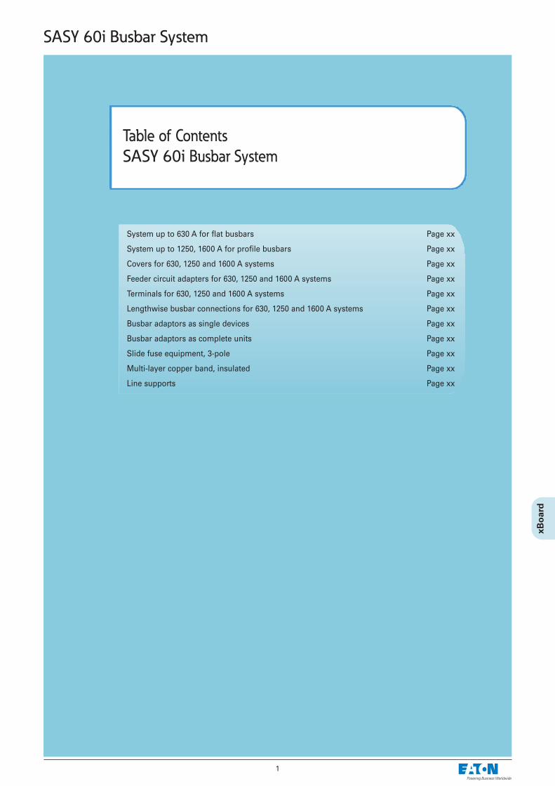
1 Table of Contents SASY 60i Busbar System SASY 60i Busbar System System up to 630 A for flat busbars Page xx System up to 1250, 1600 A for profile busbars Page xx Covers for 630, 1250 and 1600 A systems Page xx Feeder circuit adapters for 630, 1250 and 1600 A systems Page xx Terminals for 630, 1250 and 1600 A systems Page xx Lengthwise busbar connections for 630, 1250 and 1600 A systems Page xx Busbar adaptors as single devices Page xx Busbar adaptors as complete units Page xx Slide fuse equipment, 3-pole Page xx Multi-layer copper band, insulated Page xx Line supports Page xx
Transcript of SASY 60i Busbar System Table of Contents SASY 60i Busbar ...pub/@denmark/documents/content… · 3...
1
Table of Contents
SASY 60i Busbar System
SASY 60i Busbar System
System up to 630 A for flat busbars Page xx
System up to 1250, 1600 A for profile busbars Page xx
Covers for 630, 1250 and 1600 A systems Page xx
Feeder circuit adapters for 630, 1250 and 1600 A systems Page xx
Terminals for 630, 1250 and 1600 A systems Page xx
Lengthwise busbar connections for 630, 1250 and 1600 A systems Page xx
Busbar adaptors as single devices Page xx
Busbar adaptors as complete units Page xx
Slide fuse equipment, 3-pole Page xx
Multi-layer copper band, insulated Page xx
Line supports Page xx
2
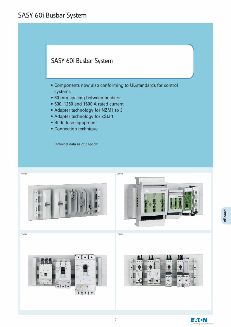
• Components now also conforming to UL-standards for controlsystems
• 60 mm spacing between busbars • 630, 1250 and 1600 A rated current• Adapter technology for NZM1 to 3• Adapter technology for xStart• Slide fuse equipment• Connection technique
SASY 60i Busbar System
SASY 60i Busbar System
VT20706 VT20806
Technical data as of page xx.
VT20106 VT20406
3
SASY 60i Busbar System
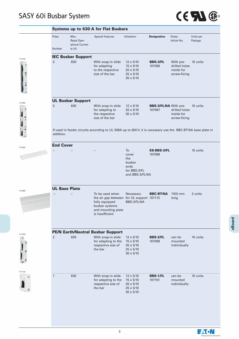
Systems up to 630 A for Flat Busbars
3 630 With snap-in slide 12 x 5/10 BBS-3/FL With pre- 10 unitsfor adapting 15 x 5/10 107066 drilled holes to the respective 20 x 5/10 inside forsize of the bar 25 x 5/10 screw-fixing
30 x 5/10
Poles Max. Special Features Utilisation Designation Notes Units perRated Oper- Article No. Packageational Current
Number Ie (A)
IEC Busbar SupportVT12706
3 630 With snap-in slide 12 x 5/10 BBS-3/FL-NA With pre- 10 unitsfor adapting to 20 x 5/10 107067 drilled holesthe respective 30 x 5/10 inside for size of the bar screw-fixing
If used in feeder circuits according to UL 508A up to 600 V, it is necessary use the BBC-BT-NA base plate inaddition.
UL Busbar SupportVT12806
– – To be used when Necessary BBC-BT-NA 1100 mm 2 unitsthe air gap between for UL support 107172 longfully equipped BBS-3/FL-NAbusbar systemsand mounting plateis insufficient
UL Base Plate VT19806
2 630 With snap-in slide 12 x 5/10 BBS-2/FL can be 10 unitsfor adapting to the 15 x 5/10 107069 mounted respective size of 20 x 5/10 individuallythe bar 25 x 5/10
30 x 5/10
PE/N Earth/Neutral Busbar SupportVT13006
1 630 With snap-in slide 12 x 5/10 BBS-1/FL can be 10 unitsfor adapting to the 15 x 5/10 107161 mountedrespective size of 20 x 5/10 individuallythe bar 25 x 5/10
30 x 5/10
VT17106
– – – To ES-BBS-3/FL 10 unitscover 107068the busbarendsfor BBS-3/FL and BBS-3/FL-NA
End CoverVT14006
4
SASY 60i Busbar System
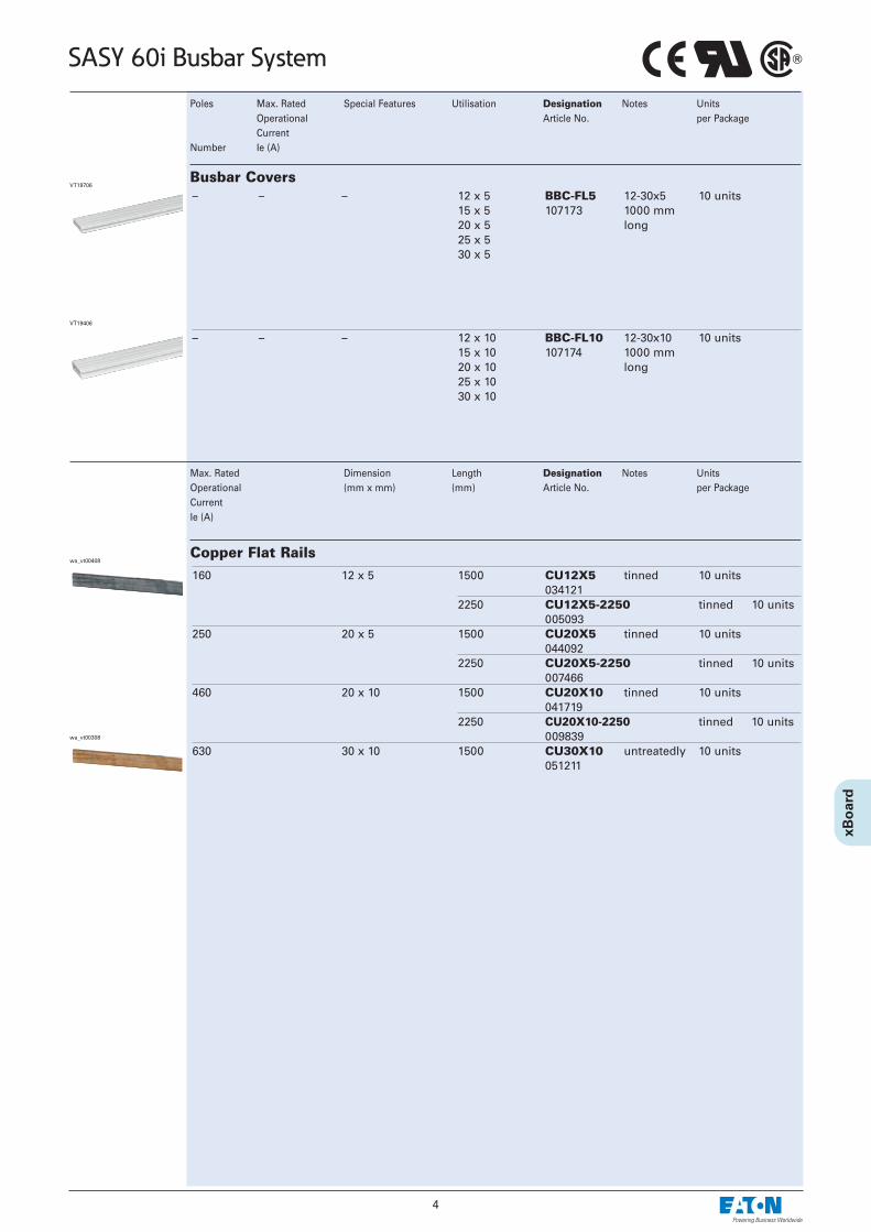
– – – 12 x 5 BBC-FL5 12-30x5 10 units15 x 5 107173 1000 mm 20 x 5 long25 x 530 x 5
Poles Max. Rated Special Features Utilisation Designation Notes Units Operational Article No. per PackageCurrent
Number Ie (A)
Busbar CoversVT19706
– – – 12 x 10 BBC-FL10 12-30x10 10 units15 x 10 107174 1000 mm20 x 10 long25 x 1030 x 10
VT19406
160 12 x 5 1500 CU12X5 tinned 10 units 034121
2250 CU12X5-2250 tinned 10 units005093
250 20 x 5 1500 CU20X5 tinned 10 units044092
2250 CU20X5-2250 tinned 10 units007466
460 20 x 10 1500 CU20X10 tinned 10 units041719
2250 CU20X10-2250 tinned 10 units 009839
630 30 x 10 1500 CU30X10 untreatedly 10 units051211
Copper Flat Railswa_vt00408
Max. Rated Dimension Length Designation Notes Units Operational (mm x mm) (mm) Article No. per PackageCurrentIe (A)
wa_vt00308

5
SASY 60i Busbar System
Systems up to 1250, 1600 A for Profile Bars
3 1600 Suitable as Double-T- BBS-3/PR With pre-drilled 3 unitslateral and central Profile 107162 holes insidesupport for screw-
fixing
Poles Max. Special Features Utilisation Designation Notes Units perRated Oper- Article No. Packageational Current
Number Ie (A)
Busbar Support Double-T-ProfileVT12906
1 1600 Suitable for Double-T- BBS-1/PR With pre-drilled 10 unitssetting up a Profile 107165 holes insidePE or for scew-N bar fixing
VT18606
– – To be used when For BBC-BT-NA 1100 mm 2 unitsthe air gap UL508A- 107172 longbetween fully systemsequipped busbar necessarilysystems and themounting plateis insufficient
UL Base Plate VT19806
– 12501) Tin-plated For CU-BAR-500/T2400 mm 1 unitCross-section BBS-3/PR 107166 long500 mm2 and
BBS-1/PRsupports
Double-T-Profile BusbarVT19206
– 16001) Tin-plated For CU-BAR-720/T 2400 mm 1 unitCross-section BBS-3/PR 107167 long720 mm2 and
BBS-1/PR supports
VT19106
– – – For the ES-BBS-3/PR 4 unitsBBS-3/PR 107164support
End CoverVT13906
– – – Fór BBC-CU-BAR/PR 1000 mm 5 unitsdouble-T- 107175 longprofile
Busbar CoverVT19506
1) At a busbar temperature of 87.5°C and an ambient temperature of 35°C, please refer to the current load diagram in theTechnical Data section for further values.

6
SASY 60i Busbar System
Covers for 630, 1250 and 1600 A Systems
To cover BBC-RCOV1 1100 mm long. 2 unitsthe front of 107178 To be used withthe 60 mm system BBC-MRCOV1
support only
Utilisation Designation Notes Units per PackageArticle No.
Spare Section Cover - ModularVT19306
Suits any thickness BBC-MRCOV1 To be used with 10 unitsof bars 107179 spare section cover
BBC-RCOV1only
For BBC-CS2-F 1100 mm long 1 unit3-pole 107180systems
System Cover - Kit
– BBC-CS2-T/B 1100 mm long 2 units107181
For BBC-MCS2 1 set 1 unit3-pole 107182 includes a systems right and left side
support
For 3-pole BBC-CS48/PR 48 mm high 1 unitsystems with 107176 2400 mm longBBS-3/PR To be fixed at the
(profile)bar support
Compartment Section Double-T VT19006
For 3-pole BBC-CS76/PR 76 mm high 1 unitsystems with 107177 2400 mm longBBS-3/PR To be fixed at the
(profile)bar support
VT18906
Support for Spare Section Cover
Cover Profile - Front
Cover Profile - Top/Bottom
Support Set for Cover Profile
VT17006
Cover module AM-195/54 54 mm width 15 unitsfor cut-out 107963Height = 195 mm
Front Plate Cover for front plate cut-outSG13506
VT12006 BBC-CS2-T/B
BBC-CS2-F
BBC-MCS2
Single covers
For BBC-CS1 228 mm long 1 unit3-pole 107209systems
Cover completeVT12006
7
SASY 60i Busbar System
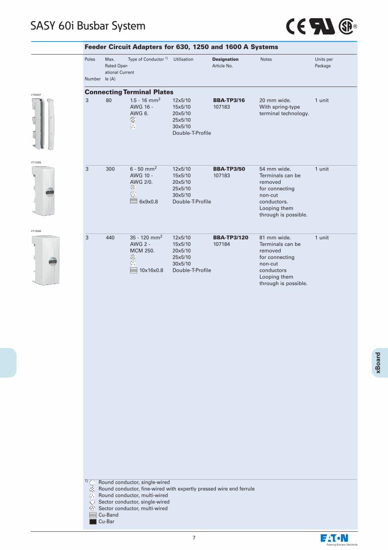
Feeder Circuit Adapters for 630, 1250 and 1600 A Systems
3 300 6 - 50 mm2 12x5/10 BBA-TP3/50 54 mm wide. 1 unitAWG 10 - 15x5/10 107183 Terminals can beAWG 2/0. 20x5/10 removed
25x5/10 for connecting30x5/10 non-cut
6x9x0.8 Double-T-Profile conductors.Looping them through is possible.
Poles Max. Type of Conductor 1) Utilisation Designation Notes Units perRated Oper- Article No. Packageational Current
Number Ie (A)
Connecting Terminal Plates
VT12306
3 440 35 - 120 mm2 12x5/10 BBA-TP3/120 81 mm wide. 1 unitAWG 2 - 15x5/10 107184 Terminals can beMCM 250. 20x5/10 removed
25x5/10 for connecting30x5/10 non-cut
10x16x0.8 Double-T-Profile conductorsLooping them through is possible.
VT12206
1) Round conductor, single-wiredRound conductor, fine-wired with expertly pressed wire end ferruleRound conductor, multi-wired Sector conductor, single-wired Sector conductor, multi-wired Cu-BandCu-Bar
3 80 1.5 - 16 mm2 12x5/10 BBA-TP3/16 20 mm wide. 1 unitAWG 16 - 15x5/10 107183 With spring-typeAWG 6. 20x5/10 terminal technology.
25x5/1030x5/10Double-T-Profile
VT05207

8
SASY 60i Busbar System
Feeder Circuit Adapters for 630, 1250 and 1600 A Systems
Poles Max. Type of Conductor 1) Utilisation Designation Notes Units perRated Oper- Article No. Packageational Current
Number Ie (A)
1) Round conductor, single-wiredRound conductor, fine-wired with expertly pressed wire end ferruleRound conductor, multi-wired Sector conductor, single-wired Sector conductor, multi-wired Cu-BandCu-Bar
3 x 1 560 120 - 300 mm2 20x5/10 BBA-TP3/300 180 - 240 mm wide. 1 unitMCM300 - 25x5/10 107185 Clearance between MCM600. 30x5/10 poles can be adjusted
Double-T-Profile as required.To be fixed directly on top of thebusbar terminal.Incl. cover cap in flexible width.1 set includes3 pole elements.Looping throughis possible.
Connecting Set with CoverVT19606
3 x 1 800 Up to 20x5/10 BBA-TP3/CU-BAND 180 - 240 mm wide. 1 unit10x32x1 25x5/10 107186 Clearance between 30x25 30x5/10 poles can be
Double-T-Profile adjusted as required.To be fixed directly on top of thebusbar terminal.Incl. cover capin flexible width.1 set includes3 pole elements.Looping through is possible.
VT19606
VT12006
VT12006
3 x 1 1600 Up to 30x10 BBA-TP3/1000 228 mm wide. 1 unit(2x)10x50x1 Double-T-Profile 107207 Co-ordinated up
Up to for Moeller NZM4.(2x)50x10 To be fixed
directly on top of thebusbar terminal.Incl. cover cap.1 set includes3 pole elements.Looping through is possible.
VT09408
VT12006
9
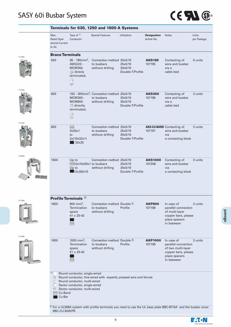
SASY 60i Busbar System
Terminals for 630, 1250 and 1600 A Systems
500 95 - 185mm2, Connection method 20x5/10 AKS185 Contacting of 6 unitsAWG3/0 - to busbars 25x5/10 107195 wire and busbarMCM350. without drilling 30x5/10 via a
directy Double-T-Profile cable bedterminated,
Max. Type of 1) Special Features Utilisation Designation Notes Units Rated Oper- Conductor Article No. per Packageational CurrentIe (A)
Brace TerminalsVT13306
600 150 - 300mm2, Connection method 20x5/10 AKS300 Contacting of 3 unitsMCM300 - to busbars 25x5/10 107196 wire and busbarMCM600. without drilling 30x5/10 via a
directly Double-T-Profile cable bedterminated,
VT13406
800 Connection method 20x5/10 AKS-CU-BAND Contacting of 3 units3x20x1 to busbars 25x5/10 107197 wire and busbarto without drilling 30x5/10 via2x(10x32x1) Double-T-Profile a contacting block
32x25
VT13206
1600 800 mm2, Connection method Double-T- AKP800 In case of 3 unitsTermination to busbars Profile 107198 parallel connectionspace without drilling of multi-layer41 x 20-42 copper bars, please
place spacers in between
Profile Terminals 2)VT17906
1600 1000 mm2, Connection method Double-T- AKP1000 In case of 3 unitsTermination to busbars Profile 107199 parallel connectionspace without drilling of two multi-layer 51 x 20-42 copper bars, please
place spacersin between
VT17806
1) Round conductor, single-wiredRound conductor, fine-wired with expertly pressed wire end ferruleRound conductor, multi-wiredSector conductor, single-wired Sector conductor, multi-wiredCu-BandCu-Bar
2) For a UL508A system with profile terminals you need to use the UL base plate BBC-BT-NA and the busbar coverBBC-CU-BAR/PR.
1600 Up to Connection method 20x5/10 AKS1000 Contacting of 3 units(2x)10x50x1 to busbars 25x5/10 107208 wire and busbar
Up to without drilling 30x5/10 via(2x)50x10 Double-T-Profile a contacting block
VT09408
10
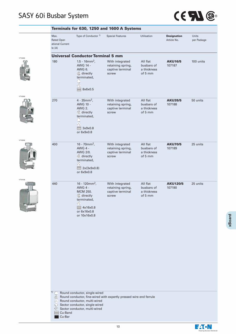
SASY 60i Busbar System
Terminals for 630, 1250 and 1600 A Systems
180 1.5 - 16mm2, With integrated All flat AKU16/5 100 unitsAWG 14 - retaining spring, busbars of 107187AWG 6. captive terminal a thickness
directly screw of 5 mmterminated,
8x6x0.5
Max. Type of Conductor 1) Special Features Utilisation Designation UnitsRated Oper- Article No. per Packageational CurrentIe (A)
Universal Conductor Terminal 5 mmVT18406
270 4 - 35mm2, With integrated All flat AKU35/5 50 unitsAWG 10 - retaining spring, busbars of 107188AWG 2. captive terminal a thickness
directly screw of 5 mmterminated,
3x9x0.8 or 6x9x0.8
VT18306
400 16 - 70mm2, With integrated All flat AKU70/5 25 unitsAWG 4 - retaining spring, busbars of 107189AWG 2/0. captive terminal a thickness
directly screw of 5 mmterminated,
2x(3x9x0.8)or 6x9x0.8
VT18206
440 16 - 120mm2, With integrated All flat AKU120/5 25 unitsAWG 4 - retaining spring, busbars of 107190MCM 250. captive terminal a thickness
directly screw of 5 mmterminated,
4x16x0.8or 6x16x0.8or 10x16x0.8
VT18106
1) Round conductor, single-wiredRound conductor, fine-wired with expertly pressed wire end ferruleRound conductor, multi-wiredSector conductor, single-wired Sector conductor, multi-wiredCu-BandCu-Bar

11
SASY 60i Busbar System
Terminals for 630, 1250 and 1600 A Systems
180 1.5 - 16mm2, With integrated All flat busbars AKU16/10 100 unitsAWG 14 - retaining spring, of a thickness 107191AWG 6. captive terminal of 10 mm
directly screwterminated,
8x6x0.5
Max. Type of Conductor 1) Special Features Utilisation Designation Units Rated Oper- Article No. per Packageational CurrentIe (A)
Universal Connection Terminal 10 mmVT13806
270 4 - 35mm2, With integrated All flat busbars AKU35/10 50 unitsAWG 10 - retaining spring, of a thickness 107192AWG 2. captive terminal of 10 mm
directly screwterminated,
3x9x0.8or 6x9x0.8
VT13706
400 16 - 70mm2, With integrated All flat busbars AKU70/10 25 unitsAWG 4 - retaining spring, of a thickness 107193AWG 2/0. captive terminal of 10 mm,
directly screw double-T-profile terminated,
2x(3x9x0.8)or 6x9x0.8
VT13606
440 16 - 120mm2, With integrated All flat busbars AKU120/10 25 unitsAWG 4 - retaining spring, of a thickness 107194MCM 250. captive terminal of 10 mm,
directly screw double-T-profileterminated,
4x16x0.8or 6x16x0.8or 10x16x0.8
VT13506
1) Round conductor, single-wiredRound conductor, fine-wired with expertly pressed wire end ferruleRound conductor, multi-wiredSector conductor, single-wired Sector conductor, multi-wired Cu-BandCu-Bar
12
SASY 60i Busbar System
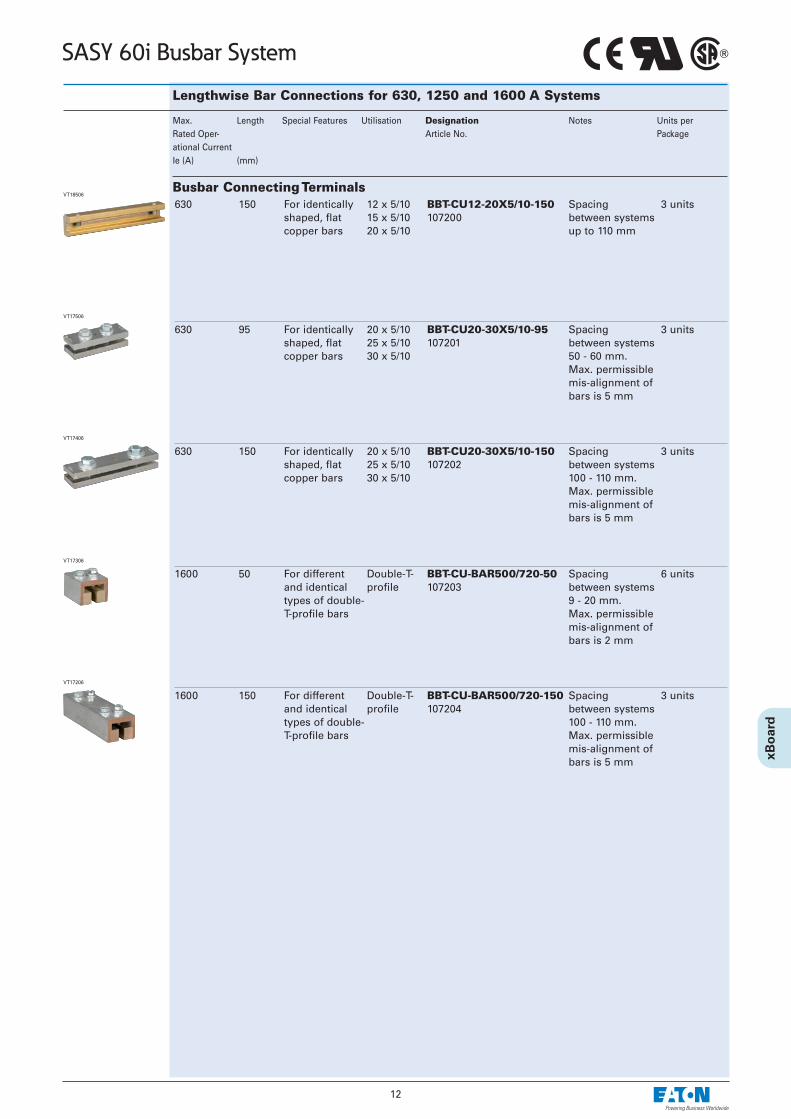
Lengthwise Bar Connections for 630, 1250 and 1600 A Systems
630 150 For identically 12 x 5/10 BBT-CU12-20X5/10-150 Spacing 3 unitsshaped, flat 15 x 5/10 107200 between systemscopper bars 20 x 5/10 up to 110 mm
Max. Length Special Features Utilisation Designation Notes Units perRated Oper- Article No. Packageational CurrentIe (A) (mm)
Busbar Connecting TerminalsVT18506
630 95 For identically 20 x 5/10 BBT-CU20-30X5/10-95 Spacing 3 unitsshaped, flat 25 x 5/10 107201 between systemscopper bars 30 x 5/10 50 - 60 mm.
Max. permissiblemis-alignment of bars is 5 mm
VT17506
630 150 For identically 20 x 5/10 BBT-CU20-30X5/10-150 Spacing 3 unitsshaped, flat 25 x 5/10 107202 between systemscopper bars 30 x 5/10 100 - 110 mm.
Max. permissiblemis-alignment of bars is 5 mm
VT17406
1600 50 For different Double-T- BBT-CU-BAR500/720-50 Spacing 6 unitsand identical profile 107203 between systemstypes of double- 9 - 20 mm.T-profile bars Max. permissible
mis-alignment of bars is 2 mm
VT17306
1600 150 For different Double-T- BBT-CU-BAR500/720-150 Spacing 3 unitsand identical profile 107204 between systemstypes of double- 100 - 110 mm.T-profile bars Max. permissible
mis-alignment of bars is 5 mm
VT17206
13
SASY 60i Busbar System
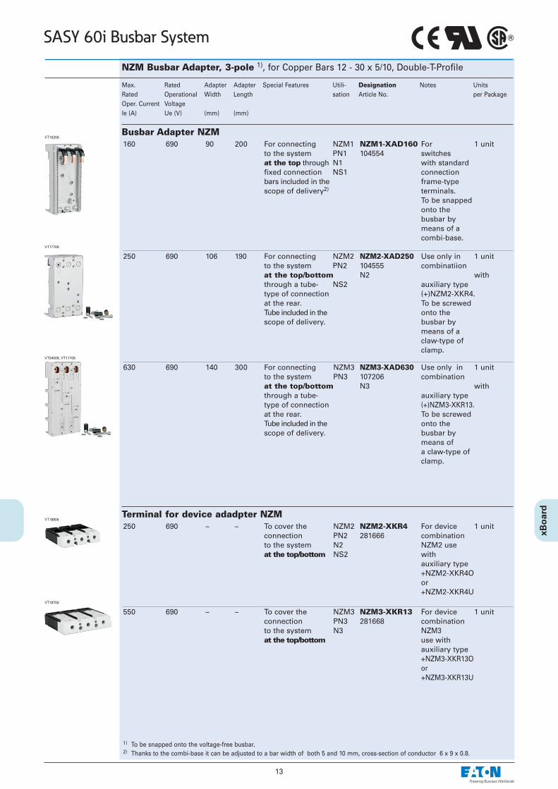
NZM Busbar Adapter, 3-pole 1), for Copper Bars 12 - 30 x 5/10, Double-T-Profile
160 690 90 200 For connecting NZM1 NZM1-XAD160 For 1 unitto the system PN1 104554 switchesat the top through N1 with standardfixed connection NS1 connectionbars included in the frame-typescope of delivery2) terminals.
To be snapped onto the busbar by means of a combi-base.
Max. Rated Adapter Adapter Special Features Utili- Designation Notes Units Rated Operational Width Length sation Article No. per PackageOper. Current VoltageIe (A) Ue (V) (mm) (mm)
Busbar Adapter NZMVT16206
250 690 106 190 For connecting NZM2 NZM2-XAD250 Use only in 1 unitto the system PN2 104555 combinatiion at the top/bottom N2 with through a tube- NS2 auxiliary type type of connection (+)NZM2-XKR4.at the rear. To be screwedTube included in the onto the scope of delivery. busbar by
means of aclaw-type of clamp.
VT17706
630 690 140 300 For connecting NZM3 NZM3-XAD630 Use only in 1 unitto the system PN3 107206 combinationat the top/bottom N3 with through a tube- auxiliary typetype of connection (+)NZM3-XKR13.at the rear. To be screwedTube included in the onto the scope of delivery. busbar by
means ofa claw-type ofclamp.
VT04008, VT17706
250 690 – – To cover the NZM2 NZM2-XKR4 For device 1 unit connection PN2 281666 combination to the system N2 NZM2 use at the top/bottom NS2 with
auxiliary type+NZM2-XKR4Oor +NZM2-XKR4U
Terminal for device adadpter NZMVT18806
550 690 – – To cover the NZM3 NZM3-XKR13 For device 1 unitconnection PN3 281668 combinationto the system N3 NZM3at the top/bottom use with
auxiliary type +NZM3-XKR13O or+NZM3-XKR13U
VT18706
1) To be snapped onto the voltage-free busbar. 2) Thanks to the combi-base it can be adjusted to a bar width of both 5 and 10 mm, cross-section of conductor 6 x 9 x 0.8.

14
SASY 60i Busbar System
xStart Busbar Adaptor, 3-pole 1)
25 690 AWG12 45 200 1 PKZM0+ BBA0-25 Direct 4 unitsContactor DIL M 7 101451 starter Contactor DIL M 9 setContactor DIL M 12 PKZM0-XDM12Contactor DIL M 15MSC-D-0.25-M7…toMSC-D-16-M15…
Max. Rated Wire Adapter Adapter Support Utilisation Designation Notes UnitsRated Oper- Operational Cross Width Length Rails Article No. per ational Current Voltage Section PackageIe (A) Ue (V) (mm) (mm)
xStart Busbar Adaptor 25 AVT15906
25 690 AWG12 90 200 1 PKZM0+ BBA0R-25 Reversing 2 units2x Contactor DIL M 7-01 101453 starter2x Contactor DIL M 9-01 set2x Contactor DIL M 12-01 PKZM0-XRM12MSC-R-0.25-M7...toMSC-R-12-M12…
VT14306
1) Can be used with all busbars in a 60 mm system. Thanks to the combi-base it is suitable for both 5 mm and 10 mm thickness of the baras well as for double-T-profile bars.
To be snapped onto the voltage-free busbar.
25 690 AWG12 45 200 2 Support rail BBA0-25/2TS 4 unitsadjustable on 101481the 1.25 mm grid
xStart Busbar Adaptor 25 A, Universal TypeVT15306
32 690 AWG10 45 200 2 PKZM0+ BBA0-32 Electrical 4 unitsContactor DIL M 17 101452 contactContactor DIL M 25 moduleContactor DIL M 32 PKZM0-XM32 DEMSC-D-16-M17...toMSC-D-32-M32…
32 690 AWG10 90 200 3 PKZM0+ BBA0R-32 Electrical 2 units2x Contactor DIL M 17-01 101454 contact2x Contactor DIL M 25-01 module2x Contactor DIL M 32-01 PKZM0-XM32 DEMSC-R-16-M17... Reverse to wiring setMSC-R-32-M32… DILM32-XRL
VT14906
32 690 – 45 200 2 Support rail BBA0-32/2TS-C With 4 unitsadjustable on 116708 spring-typethe 1.25 mm terminal grid technology,
up to 1.5-6 mm2.For examplefor 1-phaseapplikations.
xStart Busbar Adaptor 32 A, for Spring-type Terminal wa_vt00608
xStart Busbar Adaptor 32 AVT15706
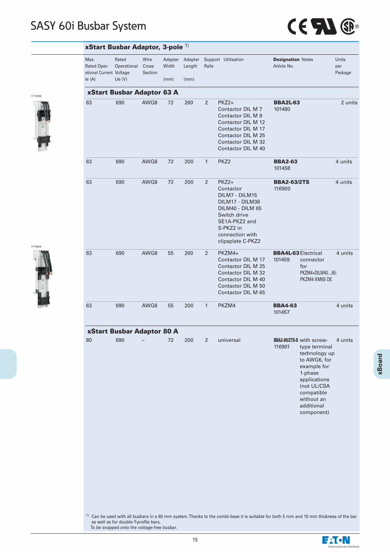
15
SASY 60i Busbar System
63 690 AWG8 72 260 2 PKZ2+ BBA2L-63 2 unitsContactor DIL M 7 101480Contactor DIL M 9Contactor DIL M 12Contactor DIL M 17Contactor DIL M 25Contactor DIL M 32Contactor DIL M 40
63 690 AWG8 72 200 1 PKZ2 BBA2-63 4 units101458
63 690 AWG8 72 200 2 PKZ2+ BBA2-63/2TS 4 unitsContactor 116900DILM7 - DILM15DILM17 - DILM38DILM40 - DILM 65Switch drive SE1A-PKZ2 andS-PKZ2 in connection withclipsplate C-PKZ2
xStart Busbar Adaptor, 3-pole 1)
Max. Rated Wire Adapter Adapter Support Utilisation Designation Notes UnitsRated Oper- Operational Cross Width Length Rails Article No. per ational Current Voltage Section PackageIe (A) Ue (V) (mm) (mm)
1) Can be used with all busbars in a 60 mm system. Thanks to the combi-base it is suitable for both 5 mm and 10 mm thickness of the baras well as for double-T-profile bars.
To be snapped onto the voltage-free busbar.
xStart Busbar Adaptor 63 A
63 690 AWG8 55 260 2 PKZM4+ BBA4L-63Electrical 4 unitsContactor DIL M 17 101459 connectorContactor DIL M 25 forContactor DIL M 32 PKZM4+DILM40…65:Contactor DIL M 40 PKZM4-XM65 DEContactor DIL M 50Contactor DIL M 65
63 690 AWG8 55 200 1 PKZM4 BBA4-63 4 units101457
VT16606
80 690 – 72 200 2 universal BBA2-80/2TS-S with screw- 4 units116901 type terminal
technology up to AWG6, for example for 1-phase applications (not UL/CSA compatible without an additional component)
VT16406
xStart Busbar Adaptor 80 A
16
SASY 60i Busbar System
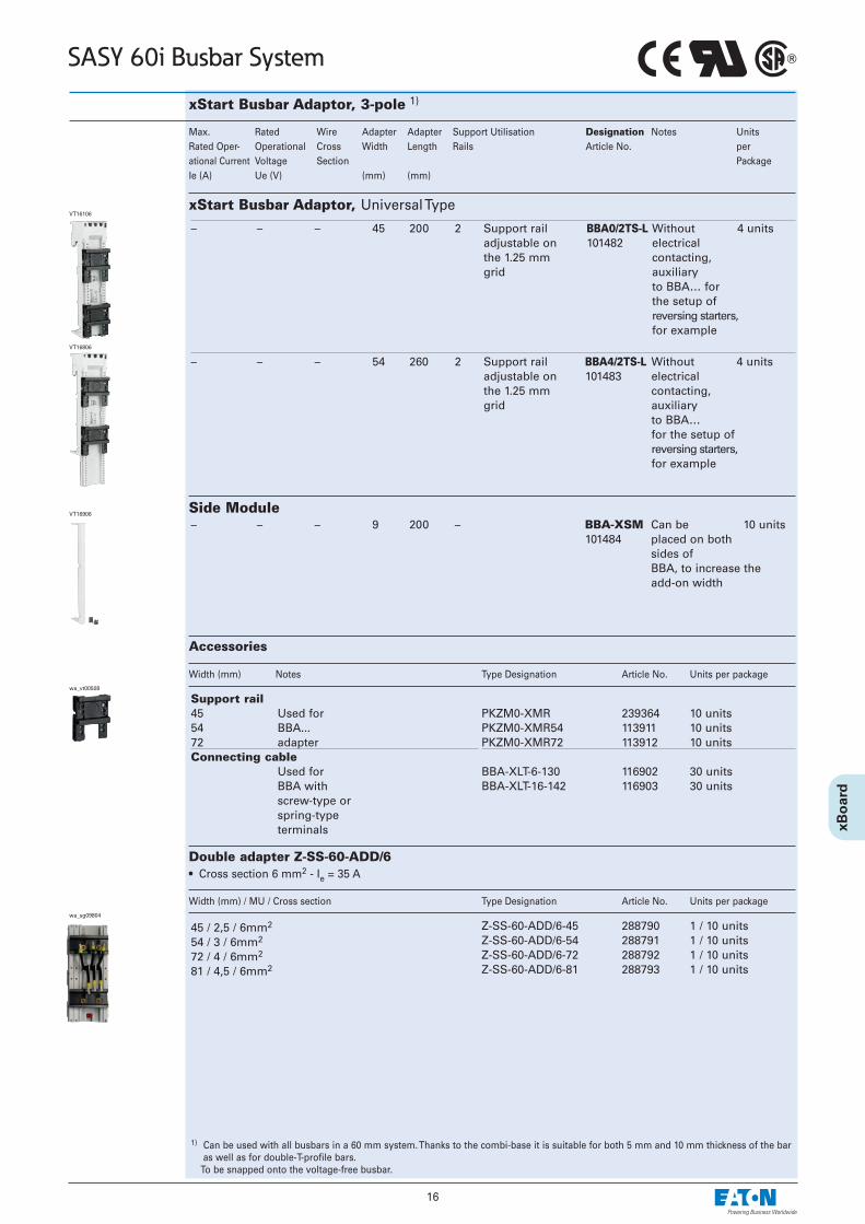
xStart Busbar Adaptor, 3-pole 1)
Max. Rated Wire Adapter Adapter Support Utilisation Designation Notes UnitsRated Oper- Operational Cross Width Length Rails Article No. per ational Current Voltage Section PackageIe (A) Ue (V) (mm) (mm)
1) Can be used with all busbars in a 60 mm system. Thanks to the combi-base it is suitable for both 5 mm and 10 mm thickness of the baras well as for double-T-profile bars.
To be snapped onto the voltage-free busbar.
– – – 45 200 2 Support rail BBA0/2TS-L Without 4 unitsadjustable on 101482 electricalthe 1.25 mm contacting,grid auxiliary
to BBA… forthe setup ofreversing starters,for example
– – – 54 260 2 Support rail BBA4/2TS-L Without 4 unitsadjustable on 101483 electricalthe 1.25 mm contacting,grid auxiliary
to BBA… for the setup ofreversing starters,for example
VT16806
xStart Busbar Adaptor, Universal Type
Double adapter Z-SS-60-ADD/6• Cross section 6 mm2 - Ie = 35 A
Width (mm) / MU / Cross section Type Designation Article No. Units per package
45 / 2,5 / 6mm2
54 / 3 / 6mm2
72 / 4 / 6mm2
81 / 4,5 / 6mm2
Z-SS-60-ADD/6-45 288790 1 / 10 unitsZ-SS-60-ADD/6-54 288791 1 / 10 unitsZ-SS-60-ADD/6-72 288792 1 / 10 unitsZ-SS-60-ADD/6-81 288793 1 / 10 units
wa_sg09804
Accessories
Width (mm) Notes Type Designation Article No. Units per package
Support rail45 Used for54 BBA...72 adapterConnecting cable
Used forBBA withscrew-type orspring-typeterminals
PKZM0-XMR 239364 10 unitsPKZM0-XMR54 113911 10 unitsPKZM0-XMR72 113912 10 units
BBA-XLT-6-130 116902 30 unitsBBA-XLT-16-142 116903 30 units
wa_vt00508
– – – 9 200 – BBA-XSM Can be 10 units101484 placed on both
sides of BBA, to increase theadd-on width
Side ModuleVT16906
VT16106
17
SASY 60i Busbar System
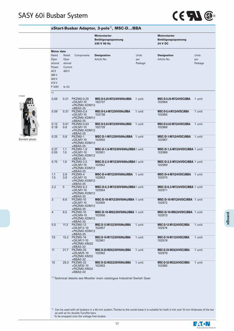
xStart-Busbar Adaptor, 3-pole1), MSC-D…/BBA
0.06 0.21 PKZM0-0,25 MSC-D-0,25-M7(230V50Hz)/BBA 1 unit MSC-D-0,25-M7(24VDC)/BBA 1 unit+DILM7-10 102737 102964+PKZM0-XDM12 +BBA0-25
0.09 0.31 PKZM0-0,4 MSC-D-0,4-M7(230V50Hz)/BBA 1 unit MSC-D-0,4-M7(24VDC)/BBA 1 unit+DILM7-10 102738 102965+PKZM0-XDM12 +BBA0-25
0.12 0.41 PKZM0-0,63 MSC-D-0,63-M7(230V50Hz)/BBA 1 unit MSC-D-0,63-M7(24VDC)/BBA 1 unit0.18 0.6 +DILM7-10 102739 102966
+PKZM0-XDM12 +BBA0-25
0.25 0.8 PKZM0-1 MSC-D-1-M7(230V50Hz)/BBA 1 unit MSC-D-1-M7(24VDC)/BBA 1 unit+DILM7-10 102950 102967+PKZM0-XDM12 +BBA0-25
0.37 1.1 PKZM0-1,6 MSC-D-1,6-M7(230V50Hz)/BBA1 unit MSC-D-1,6-M7(24VDC)/BBA 1 unit0.55 1.5 +DILM7-10 102951 102968
+PKZM0-XDM12 +BBA0-25
0.75 1.9 PKZM0-2,5 MSC-D-2,5-M7(230V50Hz)/BBA1 unit MSC-D-2,5-M7(24VDC)/BBA 1 unit+DILM7-10 102952 102969+PKZM0-XDM12 +BBA0-25
1.1 2.6 PKZM0-4 MSC-D-4-M7(230V50Hz)/BBA 1 unit MSC-D-4-M7(24VDC)/BBA 1 unit1.5 3.6 +DILM7-10 102953 102970
+PKZM0-XDM12 +BBA0-25
2.2 5 PKZM0-6,3 MSC-D-6,3-M7(230V50Hz)/BBA1 unit MSC-D-6,3-M7(24VDC)/BBA 1 unit+DILM7-10 102954 102971+PKZM0-XDM12 +BBA0-25
3 6.6 PKZM0-10 MSC-D-10-M7(230V50Hz)/BBA 1 unit MSC-D-10-M7(24VDC)/BBA 1 unit+DILM7-10 102955 102972+PKZM0-XDM12 +BBA0-25
4 8.5 PKZM0-10 MSC-D-10-M9(230V50Hz)/BBA 1 unit MSC-D-10-M9(24VDC)/BBA 1 unit+DILM9-10 102956 102973+PKZM0-XDM12 +BBA0-25
5.5 11.3 PKZM0-12 MSC-D-12-M12(230V50Hz)/BBA 1 unit MSC-D-12-M12(24VDC)/BBA 1 unit+DILM12-10 102957 102974+PKZM0-XDM12 +BBA0-25
7.5 15.2 PKZM0-16 MSC-D-16-M17(230V50Hz)/BBA 1 unit MSC-D-16-M17(24VDC)/BBA 1 unit+DILM17-10 102961 102978+PKZM0-XM32 +BBA0-32
11 21.7 PKZM0-25 MSC-D-25-M25(230V50Hz)/BBA 1 unit MSC-D-25-M25(24VDC)/BBA 1 unit+DILM25-10 102962 102979+PKZM0-XM32 +BBA0-32
15 29.3 PKZM0-32 MSC-D-32-M32(230V50Hz)/BBA 1 unit MSC-D-32-M32(24VDC)/BBA 1 unit+DILM32-10 102963 102980+PKZM0-XM32 +BBA0-32
*) Technical details see Moeller main catalogue Industrial Switch Gear
Motorstarter Motorstarter Betätigungsspannung Betätigungsspannung230 V 50 Hz 24 V DC
Motor dataRated Rated Components Designation Units Designation UnitsOper- Oper- Article No. per Article No. per ational ational Package PackagePower CurrentAC3 400 V380 V400 V415 VP (kW) Ie (A)
*)VT04608
Symbol photo
1) Can be used with all busbars in a 60 mm system. Thanks to the combi-base it is suitable for both 5 mm and 10 mm thickness of the baras well as for double-T-profile bars.
To be snapped onto the voltage-free busbar.
18
SASY 60i Busbar System
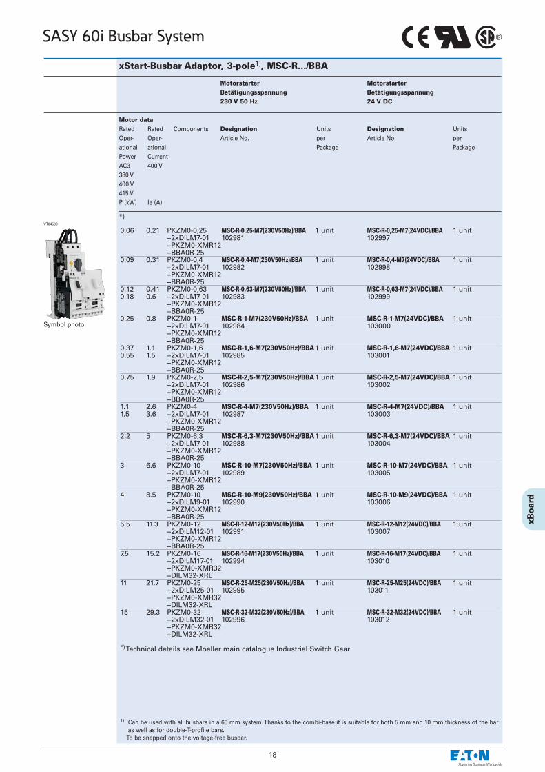
xStart-Busbar Adaptor, 3-pole1), MSC-R…/BBA
0.06 0.21 PKZM0-0,25 MSC-R-0,25-M7(230V50Hz)/BBA 1 unit MSC-R-0,25-M7(24VDC)/BBA 1 unit+2xDILM7-01 102981 102997+PKZM0-XMR12 +BBA0R-25
0.09 0.31 PKZM0-0,4 MSC-R-0,4-M7(230V50Hz)/BBA 1 unit MSC-R-0,4-M7(24VDC)/BBA 1 unit+2xDILM7-01 102982 102998+PKZM0-XMR12 +BBA0R-25
0.12 0.41 PKZM0-0,63 MSC-R-0,63-M7(230V50Hz)/BBA 1 unit MSC-R-0,63-M7(24VDC)/BBA 1 unit0.18 0.6 +2xDILM7-01 102983 102999
+PKZM0-XMR12 +BBA0R-25
0.25 0.8 PKZM0-1 MSC-R-1-M7(230V50Hz)/BBA 1 unit MSC-R-1-M7(24VDC)/BBA 1 unit+2xDILM7-01 102984 103000+PKZM0-XMR12 +BBA0R-25
0.37 1.1 PKZM0-1,6 MSC-R-1,6-M7(230V50Hz)/BBA1 unit MSC-R-1,6-M7(24VDC)/BBA 1 unit0.55 1.5 +2xDILM7-01 102985 103001
+PKZM0-XMR12 +BBA0R-25
0.75 1.9 PKZM0-2,5 MSC-R-2,5-M7(230V50Hz)/BBA1 unit MSC-R-2,5-M7(24VDC)/BBA 1 unit+2xDILM7-01 102986 103002+PKZM0-XMR12 +BBA0R-25
1.1 2.6 PKZM0-4 MSC-R-4-M7(230V50Hz)/BBA 1 unit MSC-R-4-M7(24VDC)/BBA 1 unit1.5 3.6 +2xDILM7-01 102987 103003
+PKZM0-XMR12 +BBA0R-25
2.2 5 PKZM0-6,3 MSC-R-6,3-M7(230V50Hz)/BBA1 unit MSC-R-6,3-M7(24VDC)/BBA 1 unit+2xDILM7-01 102988 103004+PKZM0-XMR12 +BBA0R-25
3 6.6 PKZM0-10 MSC-R-10-M7(230V50Hz)/BBA 1 unit MSC-R-10-M7(24VDC)/BBA 1 unit+2xDILM7-01 102989 103005+PKZM0-XMR12 +BBA0R-25
4 8.5 PKZM0-10 MSC-R-10-M9(230V50Hz)/BBA 1 unit MSC-R-10-M9(24VDC)/BBA 1 unit+2xDILM9-01 102990 103006+PKZM0-XMR12 +BBA0R-25
5.5 11.3 PKZM0-12 MSC-R-12-M12(230V50Hz)/BBA 1 unit MSC-R-12-M12(24VDC)/BBA 1 unit+2xDILM12-01 102991 103007+PKZM0-XMR12 +BBA0R-25
7.5 15.2 PKZM0-16 MSC-R-16-M17(230V50Hz)/BBA 1 unit MSC-R-16-M17(24VDC)/BBA 1 unit+2xDILM17-01 102994 103010+PKZM0-XMR32 +DILM32-XRL
11 21.7 PKZM0-25 MSC-R-25-M25(230V50Hz)/BBA 1 unit MSC-R-25-M25(24VDC)/BBA 1 unit+2xDILM25-01 102995 103011+PKZM0-XMR32 +DILM32-XRL
15 29.3 PKZM0-32 MSC-R-32-M32(230V50Hz)/BBA 1 unit MSC-R-32-M32(24VDC)/BBA 1 unit+2xDILM32-01 102996 103012+PKZM0-XMR32 +DILM32-XRL
*) Technical details see Moeller main catalogue Industrial Switch Gear
Motorstarter Motorstarter Betätigungsspannung Betätigungsspannung230 V 50 Hz 24 V DC
Motor dataRated Rated Components Designation Units Designation UnitsOper- Oper- Article No. per Article No. per ational ational Package PackagePower CurrentAC3 400 V380 V400 V415 VP (kW) Ie (A)
*)VT04508
1) Can be used with all busbars in a 60 mm system. Thanks to the combi-base it is suitable for both 5 mm and 10 mm thickness of the baras well as for double-T-profile bars.
To be snapped onto the voltage-free busbar.
Symbol photo
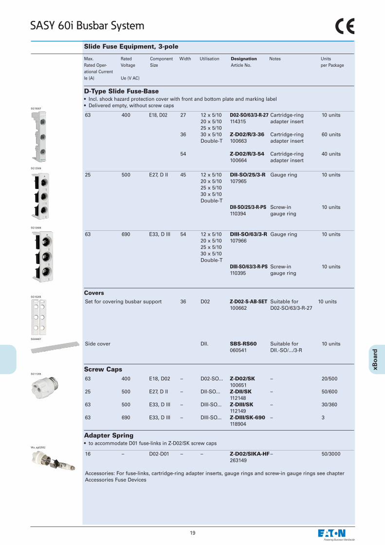
25 500 E27, D II 45 12 x 5/10 DII-SO/25/3-R Gauge ring 10 units20 x 5/10 10796525 x 5/1030 x 5/10Double-T
DII-SO/25/3-R-PS Screw-in 10 units110394 gauge ring
Max. Rated Component Width Utilisation Designation Notes UnitsRated Oper- Voltage Size Article No. per Packageational CurrentIe (A) Ue (V AC)
D-Type Slide Fuse-Base• Incl. shock hazard protection cover with front and bottom plate and marking label• Delivered empty, without screw caps
SG12506
63 400 E18, D02 27 12 x 5/10 D02-SO/63/3-R-27 Cartridge-ring 10 units20 x 5/10 114315 adapter insert25 x 5/10
36 30 x 5/10 Z-D02/R/3-36 Cartridge-ring 60 unitsDouble-T 100663 adapter insert
54 Z-D02/R/3-54 Cartridge-ring 40 units100664 adapter insert
SG15007
63 690 E33, D III 54 12 x 5/10 DIII-SO/63/3-R Gauge ring 10 units20 x 5/10 10796625 x 5/1030 x 5/10Double-T
DIII-SO/63/3-R-PS Screw-in 10 units110395 gauge ring
SG12606
Set for covering busbar support 36 D02 Z-D02-S-AB-SET Suitable for 10 units100662 D02-SO/63/3-R-27
Slide Fuse Equipment, 3-pole
CoversSG15205
63 400 E18, D02 – D02-SO... Z-D02/SK – 20/500100651
25 500 E27, D II – DII-SO... Z-DII/SK – 50/600112148
63 500 E33, D III – DIII-SO... Z-DIII/SK – 30/360112149
63 690 E33, D III – DIII-SO... Z-DIII/SK-690 – 3118904
Screw CapsSG11205
16 – D02-D01 – – Z-D02/SIKA-HF– 50/3000263149
Accessories: For fuse-links, cartridge-ring adapter inserts, gauge rings and screw-in gauge rings see chapterAccessories Fuse Devices
Adapter Spring• to accommodate D01 fuse-links in Z-D02/SK screw caps
Wa_sg02502
19
SASY 60i Busbar System
Side cover DII. SBS-RS60 Suitable for 10 units060541 DII.-SO/.../3-R
SG04407

20
SASY 60i Busbar System
63 400 E18, D02 36 20 x 5/10 D02-S/63/3-RS Cartridge-ring 10 units30 x 5/10 284649 adapter insertDouble-T
63 400 E18, D02 – D02-SO... Z-D02/SK – 20/500100651
Screw CapSG11205
16 – D02-D01 – – Z-D02/SIKA-HF– 50/3000263149
Accessories: For fuse-links, cartridge-ring adapter inserts see chapter Accessories Fuse Devices
Adapter Spring• to accommodate D01 fuse-links in Z-D02/SK screw caps
Wa_sg02502
63 400 E18, D02 27 12 x 5/10 D02-LTS/63/3-R Cartridge-ring 3 units32 400 C 10x38 15 x 5/10 114316 adapter insert
20 x 5/10 without auxiliary 25 x 5/10 switch30 x 5/10Double-T
D02-LTS/63/3-R-HK Cartridge-ring 3 units114318 adapter insert
with auxiliaryswitch
D02 Switch-Disconnector-Fuse with visual tripping indicator• Visiual tripping indicator is flashing• Delivered empty, without cartridge-ring adapter inserts and fuse-links• Delivered with adapter springs for D01-fuse-links or cylindrical fuse-links 10x38• Contact position indicator red - green• Plug-in technique without screw caps• All-pole and hand independent switching of load• Version D02-LTS/63/3-R-HK with incorporated auxliliary switch• seal- and lockable
16 – D02-D01 – – Z-D02-LTS-HF – 12 / 28832 C 10x38 114323
Accessories: For fuse-links, cartridge-ring adapter inserts see chapter Accessories Fuse Devices
Adapter Spring• to accommodate D01 fuse-links or cylindrical fuse-links 10x38 in the switch-disconnector-fuse D02-LTS/63...
SG18907
SG16007
Accessories for D02-LTS/63/3-R..fuse-links Z-D0./SE-...Cartridge-ring adapter inserts D01: Z-D02-D01/PE-...
D02: Z-D02/PE-...Adapter spring Z-D02-LTS-HF (scope of delivery)
fuse-links Z-C10/SE-...Adapter spring Z-D02-LTS-HF (scope of delivery)
See chapter Accessories Fuse Devices
D0
C
Max. Rated Component Width Utilisation Designation Notes UnitsRated Oper- Voltage Size Article No. per Packageational CurrentIe (A) Ue (V AC)
Slide Fuse Equipment, 3-pole
D02 Switch-Disconnector-Fuse• Incl. shock hazard protection cover with front and bottom plate• Delivered empty, without screw caps
SG18705
21
SASY 60i Busbar System
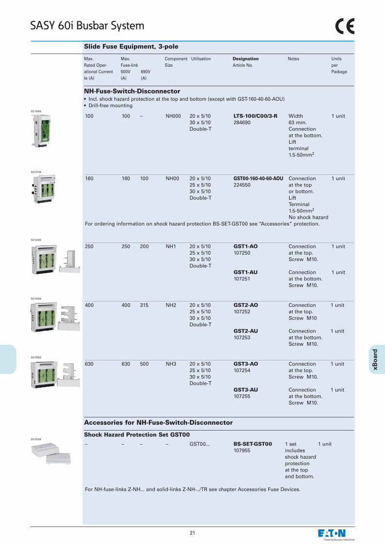
Slide Fuse Equipment, 3-pole
100 100 – NH000 20 x 5/10 LTS-100/C00/3-R Width 1 unit30 x 5/10 284690 63 mm.Double-T Connection
at the bottom.Liftterminal1.5-50mm2
Max. Max. Component Utilisation Designation Notes UnitsRated Oper- Fuse-link Size Article No. per ational Current 500V 690V PackageIe (A) (A) (A)
NH-Fuse-Switch-Disconnector• Incl. shock hazard protection at the top and bottom (except with GST-160-40-60-AOU)• Drill-free mounting
SG10006
160 160 100 NH00 20 x 5/10 GST00-160-40-60-AOU Connection 1 unit25 x 5/10 224550 at the top30 x 5/10 or bottom.Double-T Lift
Terminal1.5-50mm2
No shock hazard For ordering information on shock hazard protection BS-SET-GST00 see “Accessories” protection.
SG10106
250 250 200 NH1 20 x 5/10 GST1-AO Connection 1 unit25 x 5/10 107250 at the top.30 x 5/10 Screw M10.Double-T
GST1-AU Connection 1 unit107251 at the bottom.
Screw M10.
SG10306
400 400 315 NH2 20 x 5/10 GST2-AO Connection 1 unit25 x 5/10 107252 at the top.30 x 5/10 Screw M10Double-T
GST2-AU Connection 1 unit107253 at the bottom.
Screw M10.
SG10406
630 630 500 NH3 20 x 5/10 GST3-AO Connection 1 unit25 x 5/10 107254 at the top.30 x 5/10 Screw M10.Double-T
GST3-AU Connection 1 unit107255 at the bottom.
Screw M10.
SG10506
Accessories for NH-Fuse-Switch-Disconnector
– – – – GST00... BS-SET-GST00 1 set 1 unit107955 includes
shock hazardprotection at the top and bottom.
For NH-fuse-links Z-NH... and solid-links Z-NH-../TR see chapter Accessories Fuse Devices.
Shock Hazard Protection Set GST00SG10206
22
SASY 60i Busbar Systems
Slide Fuse Equipment, 3-pole
Rated Oper- Component Utilisation Designation Notes Units ational Voltage Size Article No. per Package
70-150 mm2 GST1... PSK1 One set includes 1 unit038734 3 prism terminals
120-240 mm2 GST2... PSK2 One set includes 1 unit043480 3 prism terminals
120-300 mm2 GST3… PSK3 One set includes 1 unit048226 3 prism terminals
2x(70-95) mm2 GST1... PSK12 One set includes 1 unit041107 3 double-
prism terminals2x(120-150) mm2 GST2... PSK22 One set includes 1 unit
045853 3 double-prism terminals
2x(120-240) mm2 GST3… PSK32 One set includes 1 unit050599 3 double-
prism terminals
25-150 mm2 GST1... SK1-GS 3 unitsCu-Band 6 x 16 x 0.8 mm 107960
25-240 mm2 GST2... SK2-GS 3 unitsCu-Band 10 x 16 x 0.8 mm 107961
25-300 mm2 GST3… SK3-GS 3 unitsCu-Band 11 x 21 x 1 mm 107962
Set of Prism Terminals wa_vt00406
Set of Double-Prism Terminalswa_vt00506
Clamp-Type Terminalwa_vt00306
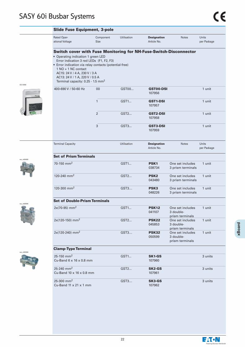
Switch cover with Fuse Monitoring for NH-Fuse-Switch-Disconnector• Operating indication 1 green LED
Error indication 3 red LEDs (F1, F2, F3)• Error indication via relay contacts (potential-free)
1 NO + 1 NC contactAC15: 24 V / 4 A, 230 V / 3 AAC13: 24 V / 1 A, 220 V / 0.5 ATerminal capacity: 0.25 - 1.5 mm2
400-690 V / 50-60 Hz 00 GST00... GST00-DSI 1 unit107956
1 GST1... GST1-DSI 1 unit107957
2 GST2... GST2-DSI 1 unit107958
3 GST3... GST3-DSI 1 unit107959
SG12906
Terminal Capacity Utilisation Designation Notes Units Article No. per Package
23
SASY 60i Busbar Systems
Slide Fuse Equipment, 3-pole
Max. Max. Component Utilisation Designation Notes UnitsRated Oper- Fuse-link Size Article No. per ational Current 400V 690V PackageIe (A) (A) (A)
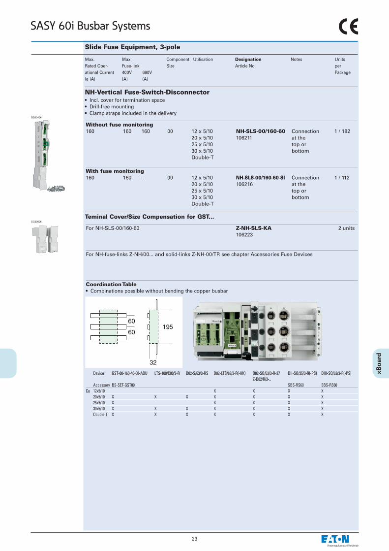
NH-Vertical Fuse-Switch-Disconnector• Incl. cover for termination space• Drill-free mounting • Clamp straps included in the delivery
SG00406
Without fuse monitoring160 160 160 00 12 x 5/10 NH-SLS-00/160-60 Connection 1 / 182
20 x 5/10 106211 at the25 x 5/10 top or30 x 5/10 bottomDouble-T
With fuse monitoring160 160 – 00 12 x 5/10 NH-SLS-00/160-60-SI Connection 1 / 112
20 x 5/10 106216 at the25 x 5/10 top or30 x 5/10 bottomDouble-T
For NH-SLS-00/160-60 Z-NH-SLS-KA 2 units106223
For NH-fuse-links Z-NH/00... and solid-links Z-NH-00/TR see chapter Accessories Fuse Devices
Teminal Cover/Size Compensation for GST...SG00606
Coordination Table • Combinations possible without bending the copper busbar
Device GST-00-160-40-60-AOU LTS-100/C00/3-R D02-S/63/3-RS D02-LTS/63/3-R(-HK) D02-SO/63/3-R-27 DII-SO/25/3-R(-PS) DIII-SO/63/3-R(-PS)Z-D02/R/3-..
Accessory BS-SET-GST00 SBS-RS60 SBS-RS60Cu 12x5/10 X X X X
20x5/10 X X X X X X X25x5/10 X X X X X30x5/10 X X X X X X XDouble-T X X X X X X X
24
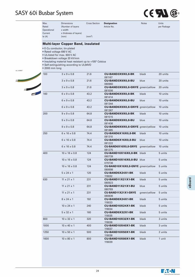
SASY 60i Busbar System
100 3 x 9 x 0.8 21.6 CU-BAND3X9X0,8-BK black 20 units081167
3 x 9 x 0.8 21.6 CU-BAND3X9X0,8-BU blue 20 units080960
3 x 9 x 0.8 21.6 CU-BAND3X9X0,8-GNYE green/yellow 20 units081006
160 6 x 9 x 0.8 43.2 CU-BAND6X9X0,8-BK black 10 units081414
6 x 9 x 0.8 43.2 CU-BAND6X9X0,8-BU blue 10 units081344
6 x 9 x 0.8 43.2 CU-BAND6X9X0,8-GNYE green/yellow 10 units081367
200 9 x 9 x 0.8 64.8 CU-BAND9X9X0,8-BK black 10 units081515
9 x 9 x 0.8 64.8 CU-BAND9X9X0,8-BU blue 10 units081436
9 x 9 x 0.8 64.8 CU-BAND9X9X0,8-GNYE green/yellow 10 units081485
250 6 x 16 x 0.8 74.4 CU-BAND6X16X0,8-BK black 10 units081310
6 x 16 x 0.8 74.4 CU-BAND6X16X0,8-BU blue 10 units081222
6 x 16 x 0.8 74.4 CU-BAND6X16X0,8-GNYE green/yellow 10 units081275
400 10 x 16 x 0.8 124 CU-BAND10X16X0,8-BK black 5 units080739
10 x 16 x 0.8 124 CU-BAND10X16X0,8-BU blue 5 units079736
10 x 16 x 0.8 124 CU-BAND10X16X0,8-GNYE green/yellow 5 units080698
5 x 24 x 1 120 CU-BAND5X24X1-BK black 5 units119032
630 11 x 21 x 1 231 CU-BAND11X21X1-BK black 5 units080923
11 x 21 x 1 231 CU-BAND11X21X1-BU blue 5 units080769
11 x 21 x 1 231 CU-BAND11X21X1-GNYE green/yellow 5 units080836
8 x 24 x 1 192 CU-BAND8X24X1-BK black 5 units119033
10 x 24 x 1 240 CU-BAND10X24X1-BK black 5 units119034
5 x 32 x 1 160 CU-BAND5X32X1-BK black 5 units119035
800 10 x 32 x 1 320 CU-BAND10X32X1-BK black 3 units119036
1000 10 x 40 x 1 400 CU-BAND10X40X1-BK black 3 units119037
1250 10 x 50 x 1 500 CU-BAND10X50X1-BK black 2 units119038
1600 10 x 80 x 1 800 CU-BAND10X80X1-BK black 1 unit119039
Max. Dimensions Cross Section Designation Notes UnitsRated (Number of layers Article No. per Package Operational x widthCurrent x thickness of layers)Ie (A) (mm) (mm2)
Multi-layer Copper Band, insulated• E-Cu conductor, tin-plated• Rated voltage 690 V AC• UL-listed for max. 600 V AC• Breakdown voltage 20 kV/mm• Insulating material heat resistant up to +105° Celsius• Self-extinguishing according to UL94VO• 2000 mm long
wa_vt04807

25
SASY 60i Busbar System
Used for Designation Notes UnitsArticle No. per Package
Profile ledge Clamp clips BZ248 10 units076516
Line supports (Short-circuit strength diagrams see Technical Datas)VT04808
Clamp clips 3 x 9 x 0.8 BZ249 10 units6 x 9 x 0.8 0788894 x 16 x 0.8 BZ251 10 units6 x 16 x 0.8 08126210 x 16 x 0.811 x 21 x 1 BZ252 10 units
083635
VT06008