
SASY 60i Busbar System - Moeller
50
www.moellerhome.net We keep power under control. Product Catalogue 2006/2007 SASY 60i valid from Oktober 2006 SASY 60i the consistent, UL-certified solution for power distribution and for switching, controlling and protecting your equipment. A space-saving desing ideal for mechanical and systems engineering. Metering boards Compact Distribution Boxes Flat Distribution Boards Installation Distribution Boards Add-on Distribution Boards Accessories
Transcript of SASY 60i Busbar System - Moeller

We keep power under control.
www.moellerhome.net
We keep power under control.
Product Catalogue 2006/2007
SASY 60i valid from Oktober 2006Moeller GmbH
Hein-Moeller-Str. 7-11D-53115 Bonn
E-Mail: [email protected]: www.moeller.net
© 2007 by Moeller GmbHSubject to alterationFK4300-1167 GB (04/07)Printed in Austria (04/07)Grafic: Werbeweber, SchremsDigiPics, Lithos: Jonas, HeidenreichsteinDruck: Rabl, SchremsArticle No.
With Xclever home, Moeller offers the completeelectrical installation from one source for a safeand easily controllable building. All Xclever homeproduct groups stand out because of their highsafety standards and simple and easy application.
Combines all functional and assembly safety advantages. From circuit-breakers and modular installation devices to over-voltage protection.
The complete distribution program for safe electrical installations from 63 to 2500 Amps. For houses, blocks of flats or functional buildings.
Covers all requirements of operation in buildings. The system opens new business possibilities for new and renovated buildings.
A clever, complete range that can be flexibly extended for the installation of future-orientated data networks.
GermanyInternet: www.moeller.net
BerlinMoeller Electric GmbHMoeller Haus BerlinUllsteinstraße 8712109 Berlin Tel. (0 30) 70 19 02-0Fax (0 30) 70 19 02-39E-Mail: [email protected]
Düsseldorf Moeller Electric GmbHMoeller Haus DüsseldorfIm Taubental 3241468 Neuss Tel. (0 21 31) 3 17-0Fax (0 21 31) 3 17-2 76E-Mail: [email protected]
FrankfurtMoeller Electric GmbHMoeller Haus FrankfurtBerner Straße 11160437 Frankfurt Tel. (0 69) 5 00 89-0 Fax (0 69) 5 00 89-2 70E-Mail: [email protected]
Hamburg Moeller Electric GmbHMoeller Haus HamburgGeorgswerder Bogen 321109 Hamburg Tel. (0 40) 7 50 19-0 Fax (0 40) 7 50 19-2 69E-Mail: [email protected]
MünchenMoeller Electric GmbHMoeller Haus MünchenWernher-von-Braun-Straße 585640 Putzbrunn Tel. (0 89) 4 60 95-0 Fax (0 89) 4 60 95-2 67E-Mail: [email protected]
StuttgartMoeller Electric GmbHMoeller Haus StuttgartSchelmenwasenstraße 3270567 Stuttgart Tel. (07 11) 6 87 89-0 Fax (07 11) 6 87 89-99E-Mail: [email protected]
SASY 60i the consistent,
UL-certified solution for power
distribution and for switching,
controlling and protecting your
equipment.
A space-saving desing ideal for
mechanical and systems
engineering.
Metering boards
CompactDistribution Boxes
Flat DistributionBoards
InstallationDistribution Boards
Add-on DistributionBoards
Accessories

Moeller has accepted the challenge
To stay successful together with our customers in the future as well, it is
natural for us to adapt our products to changing realties on the North
American market. A lean and yet varied range of products, a high level
of flexibility and of course absolute safety - all these attributes are syn-
onyms for Moeller’s new SASY 60i busbar system.
New requirements of the UL 508A Standard for Industrial Control Panels
result in limitations with regard to the IEC stipulations for current load
on busbars: In North America, the current carrying capacity of copper
busbars has been fixed at 1.55 A / mm2 .
For a cross-section area of 300 mm2 (busbar of 30 x 10 mm) this means
a maximum permissible current of 465 A, while IEC allows a maximum
current of 630 A.
With Moeller’s new double T-profile bars it is possible to achieve a maxi-
mum permissible current of 1116A in accordance with UL stipulations.
Busbar systems are now more frequently designed without fusible cut-
outs. So adapters directly and comfortably contact motor protective
and power switches up to 630 A on the busbars without drilling.
Moeller - Customer-focused and Innovative
SASY 60i - now a UL-certified Component

SASY 60i - The Innovative Busbar System -
now UL-508A listed
SASY 60i - the Busbar System
for the Global Market
Consistent, customer-focused and innovative - this is
how Moeller now provides a solution for using busbar
systems complying with UL 508A requirements for the
North American type of industrial control panels. This
kind of space-saving design has established itself espe-
cially in the mechanical engineering and systems busi-
ness.
A crucial aspect of the success we share with our cus-
tomers was to adapt the 60 mm system to the larger air
gaps and longer creepage distances required in North
America. And we have successfully managed this techni-
cal challenge.
With SASY 60i - in combination with the new generation
of motor protection and circuit breakers - Moeller is one
of the first suppliers to offer a consistent, UL-certified
solution allowing to distribute power and to switch, con-
trol and protect equipment at the same time.

Challenge: Use in compliance with the UL 508A
Standard.
Requirements for the North American market are defined in the National Electrical
Code (NEC), and Underwriters Laboratories (UL) develops the corresponding stan-
dards. Companies can ask Underwriters Laboratories to test and approve their prod-
ucts.
The UL 508A Standard covers the use of components for industrial control equip-
ment. According to this Standard, any equipment for the control of systems and for
monitoring and protecting motors belongs to the category of “Industrial Control
Panels”.
Therefore there are new requirements applicable for voltage gaps in UL 508A test-
ed products. The following criteria need to be considered:
• the air gap must be 1 inch (corresponding to 25.4 mm) and
• the creepage distance must be 2 inches (corresponding to 50.8 mm).
In case any grounded, non-insulated metal parts are used - such as mounting
plates - the air gap and the creepage distance must be 1 inch. These distances are
much larger than those required in the IEC standard.
For the type of busbar systems commonly used in Europe and frequently exported
to North America, especially within the mechanical engineering business, these
requirements imply changes in the detail.

End cover for busbarsupport
Busbar supportDouble-T-profile1-pole
Busbar supportDouble-T-profile3-pole
Double T-ProfileBusbar
Support for ReserveSection cover
Compartment SectionDouble-T
Conductor terminal
End cover forbus-bar support
Terminal plate
Connectingset
ReserveSection cover
Brace terminal
IEC busbar support

Fuse switch dis-connector NH1-3
Busbar adaptorNZM 1
Busbar adaptorNZM 2
Fuse switch dis-connector NH00
Fuse switch dis-connector NH000
Busbar adaptorPKZM0
Busbar adaptorNZM 3
Switch disconnectorD02
Universal adaptor
Busbar adaptorPKZM4
Busbar adaptorPKZ2
UL busbar support
UL base plate

6
Table oof CContentsSASY 60i Busbar SSystem
SASY 60i Busbar System
System up to 630 A for flat busbars Page 8
System up to 1250, 1600 A for profile busbars Page 10
Covers for 630, 1250 and 1600 A systems Page 11
Feeder circuit adapters for 630, 1250 and 1600 A systems Page 12
Terminals for 630, 1250 and 1600 A systems Page 13
Lengthwise busbar connections for 630, 1250 and 1600 A systems Page 16
Busbar adaptors Page 17
Slide fuse equipment, 3-pole Page 20
Multi-layer copper band, insulated Page 23

7
• Components now also conforming to UL-standards for con-trol systems
• 60 mm spacing between busbars • 630, 1250 and 1600 A of rated current• Adapter technology for NZM1 to 3• Adapter technology for xStart• Slide fuse equipment
SASY 660i BBusbar SSystem
SASY 60i Busbar System
VT20706 VT20806
Technical data as of page xx.
VT20106 VT20406

8
SASY 60i Busbar System
Systems uup tto 6630 AA ffor FFlat BBusbars
3 630 With snap-in slide 12 x 5/10 BBBBSS-33//FFLL With pre- 10 unitsfor adapting 15 x 5/10 107066 drilled holes to the respective 20 x 5/10 inside forsize of the bar 25 x 5/10 screw-fixing
30 x 5/10
Poles Max. Special Features Utilisation DDeessiiggnnaattiioonn Notes Units perRated- Article No. PackageOperating Current
Number Ie (A)
IEC BBusbar SSupportVT12706
3 630 With snap-in slide 12 x 5/10 BBBBSS-33//FFLL-NNAA With pre- 10 unitsfor adapting to 20 x 5/10 107067 drilled holesthe respective 30 x 5/10 inside for size of the bar screw-fixing
If used in feeder circuits according to UL 508A up to 600 V, it is necessary use the BBC-BT-NA base plate in addi-tion.
UL BBusbar SSupportVT12806
– – To be used when Necessary BBBBCC-BBTT-NNAA 1100 mm 2 unitsthe air gap between for UL support 107172 longfully equipped BBS-3/FL-NAbusbar systemsand mounting plateis insufficient
UL BBase PPlate VT19806
2 630 With snap-in slide 12 x 5/10 BBBBSS-22//FFLL can be 10 unitsfor adapting to the 15 x 5/10 107069 mounted respective size of 20 x 5/10 individuallythe bar 25 x 5/10
30 x 5/10
PE/N EEarth/Neutral BBusbar SSupportVT13006
1 630 With snap-in slide 12 x 5/10 BBBBSS-11//FFLL can be 10 unitsfor adapting to the 15 x 5/10 107161 mountedrespective size of 20 x 5/10 individuallythe bar 25 x 5/10
30 x 5/10
VT17106
– – – To EESS-BBBBSS-33//FFLL 10 unitscover 107068the busbarendsfor BBS-3/FL and BBS-3/FL-NA
End CCoverVT14006

9
SASY 60i Busbar System
– – – 12 x 5 BBBBCC-FFLL55 12-30x5 10 units15 x 5 107173 1000 mm 20 x 5 long25 x 530 x 5
Poles Max. Rated Special Features Utilisation DDeessiiggnnaattiioonn Notes Units Operating Article No. per PackageCurrent
Number Ie (A)
Busbar CCoversVT19706
– – – 12 x 10 BBBBCC-FFLL1100 12-30x10 10 units15 x 10 107174 1000 mm20 x 10 long25 x 1030 x 10
VT19406

10
SASY 60i Busbar System
Systems uup tto 11250, 11600 AA ffor PProfile BBars
3 1600 Suitable as Double-T- BBBBSS-33//PPRR With pre-drilled 3 unitslateral and central Profile 107162 holes insidesupport for screw-
fixing
Poles Max. Special Features Utilisation DDeessiiggnnaattiioonn Notes Units perRated Article No. PackageOperating Current
Number Ie (A)
Busbar SSupport DDouble-TT-PProfileVT12906
1 1600 Suitable for Double-T- BBBBSS-11//PPRR With pre-drilled 10 unitssetting up a Profile 107165 holes insidePE or for scew-N bar fixing
VT18606
– – To be used when For BBBBCC-BBTT-NNAA 1100 mm 2 unitsthe air gap UL508A- 107172 longbetween fully systemsequipped busbar use AKP ...systems and profile terminalsmounting plateis insufficient
UL BBase PPlate VT19806
– 12501) Tin-plated For CCUU-BBAARR-550000//TT 2400 mm 1 unitCross-section BBS-3/PR 107166 long500 mm2 and
BBS-1/PRsupports
Double-TT-PProfile BBusbarVT19206
– 16001) Tin-plated For CCUU-BBAARR-772200//TT 2400 mm 1 unitCross-section BBS-3/PR 107167 long720 mm2 and
BBS-1/PR supports
VT19106
– – – For the EESS-BBBBSS-33//PPRR 4 unitsBBS-3/PR 107164support
End CCoverVT13906
– – – Fór BBC-CCU-BBAR/PR 1000 mm 5 unitsdouble-T- 107175 longprofile
Busbar CCoverVT19506
1) At a busbar temperature of 87.5°C and an ambient temperature of 35°C, please refer to the current loaddiagram on technic part for further values.

11
SASY 60i Busbar System
Covers ffor 6630, 11250 aand 11600 AA SSystems
To cover BBBBCC-RRCCOOVV11 1100 mm long. 2 unitsthe front of 107178 To be used withthe 60 mm system BBC-MRCOV1
support only
Utilisation DDeessiiggnnaattiioonn Notes Units per PackageArticle No.
Reserve SSection CCover - MModularVT19306
Suits any thickness BBBBCC-MMRRCCOOVV11 To be used with 10 unitsof bars 107179 reserve section cover
BBC-RCOV1only
For BBBBCC-CCSS22-FF 1100 mm long 1 unit3-pole 107180systems
System CCover - MModular
12x5/10 BBBBCC-CCSS22-TT//BB 1100 mm long 2 units20x5/10 10718125x5/1030x5/10
For BBBBCC-MMCCSS22 1 set 1 unit3-pole 107182 includes a systems right and left side
support
For 3-pole BBBBCC-CCSS4488//PPRR 48 mm high 1 unitsystems with 107176 2400 mm longBBS-3/PR To be fixed at the
(profile)bar support
Compartment SSection DDouble-TT VT19006
For 3-pole BBBBCC-CCSS7766//PPRR 76 mm high 1 unitsystems with 107177 2400 mm longBBS-3/PR To be fixed at the
(profile)bar support
VT18906
Support ffor RReserve SSection CCover
Cover PProfile - FFrontVT12006
Cover PProfile - TTop/Bottom
Support SSet ffor CCover PProfile
VT17006
VT12106

12
SASY 60i Busbar System
Feeder CCircuit AAdapters ffor 6630, 11250 aand 11600 AA SSystems
3 300 6 - 50 mm2 12x5/10 BBBBAA-TTPP33//5500 54 mm wide. 1 unitAWG 10 - 15x5/10 107183 Terminals can beAWG 2/0. 20x5/10 removed
25x5/10 for connecting30x5/10 non-cut
6X9X0.8 Double-T-Profile conductors.Looping them through is possible.
Poles Max. Type of Conductor 1) Utilisation DDeessiiggnnaattiioonn Notes Units perRated Operating Article No. PackageCurrent
Number Ie (A)
Connecting TTerminal PPlatesVT12306
3 440 35 - 120 mm2 12x5/10 BBBBAA-TTPP33//112200 81 mm wide. 1 unitAWG 2 - 15x5/10 107184 Terminals can beMCM 250. 20x5/10 removed
25x5/10 for connecting30x5/10 non-cut
10X16X0.8 Double-T-Profile conductorsLooping them through is possible.
VT12206
3 x 1 560 120 - 300 mm2 20x5/10 BBBBAA-TTPP33//330000 180 - 240 mm wide. 1 unitMCM300 - 25x5/10 107185 Clearance between MCM600. 30x5/10 poles can be adjusted
Double-T-Profile as required.To be fixed directly on top of thebusbar terminal.Incl. cover cap in flexible width.1 set includes3 pole elements.Looping throughis possible.
Connecting SSet wwith CCoverVT19606
3 x 1 800 Up to 20x5/10 BBA-TTP3/CU-BBAND 180 - 240 mm wide 1 unit10X32X1 25x5/10 107186 Clearance between
30x5/10 poles can be Double-T-Profile adjusted as required.
To be fixed directly on top of thebusbar terminal.Incl. cover capin flexible width.1 set includes3 pole elements.Looping through is possible.
VT19606
1) Round conductor, single-wiredRound conductor, fine-wired with expertly pressed wire end ferruleRound conductor, multi-wired Sector conductor, single-wired Sector conductor, multi-wired Cu-BandCu-Bar
VT12006
VT12006

13
SASY 60i Busbar System
Terminals ffor 6630, 11250 aand 11600 AA SSystems
500 95 - 185mm2, 20x5/10 AAKKSS118855 Contacting of 6 unitsAWG3/0 - Connection method 25x5/10 107195 wire and busbarMCM350. to busbars 30x5/10 via a
directy without drilling Double-T-Profile cable bedterminated,
Max. Type of 1) Special Features Utilisation DDeessiiggnnaattiioonn Notes Units Rated Operating Conductor Article No. per PackageCurrentIe (A)
Brace TTerminalsVT13306
600 150 - 300mm2, 20x5/10 AAKKSS330000 Contacting of 3 unitsMCM300 - Connection method 25x5/10 107196 wire and busbarMCM600. to busbars 30x5/10 via a
directly without drilling Double-T-Profile cable bedterminated,
VT13406
800 20x5/10 AAKKSS-CCUU-BBAANNDD Contacting of 3 units3x20x1 Connection method 25x5/10 107197 wire and busbarbis to busbars 30x5/10 via2x(10x32x1) without drilling Double-T-Profile a contacting block
VT13206
1600 800 mm2, Double-T- AAKKPP880000 In case of 3 unitsTermination Connection method Profile 107198 parallel connectionspace to busbars of multi-layer41 x 20-42 without drilling copper bars, please
place spacers in between
Profile TTerminals 2)VT17906
1600 1000 mm2, Double-T- AAKKPP11000000 In case of 3 unitsTermination Connection method Profile 107199 parallel connectionspace to busbars of two multi-layer 51 x 20-42 without drilling copper bars, please
place spacersin between
VT17806
1) Round conductor, single-wiredRound conductor, fine-wired with expertly pressed wire end ferruleRound conductor, multi-wiredSector conductor, single-wired Sector conductor, multi-wiredCu-BandCu-bar
2) For a UL508A system with profile terminals you need to use the UL base plate BBC-BT-NA and the busbar coverBBC-CU-BAR/PR.

14
SASY 60i Busbar System
Terminals ffor 6630, 11250 aand 11600 AA SSystems
180 1.5 - 16mm2, With integrated All flat AAKKUU1166//55 100 unitsAWG 14 - retaining spring, busbars of 107187AWG 6. impossible to lose a thickness
directly the terminal screw of 5 mmterminated,
8x6x0.5
Max. Type of Conductor 1) Special Features Utilisation DDeessiiggnnaattiioonn UnitsRated Article No. per PackageOperating CurrentIe (A)
Universal CConductor TTerminal 55 mmmVT18406
270 4 - 35mm2, With integrated All flat AAKKUU3355//55 50 unitsAWG 10 - retaining spring, busbars of 107188AWG 2. impossible to lose a thickness
directly the terminal screw of 5 mmterminated,
3x9x0.8 or 6x9x0.8
VT18306
400 16 - 70mm2, With integrated All flat AAKKUU7700//55 25 unitsAWG 4 - retaining spring, busbars of 107189AWG 2/0. impossible to lose a thickness
directly the terminal screw of 5 mmterminated,
2x(3x9x0.8)or 6x9x0.8
VT18206
440 16 - 120mm2, With integrated All flat AAKKUU112200//55 25 unitsAWG 4 - retaining spring, busbars of 107190MCM 250. impossible to lose a thickness
directly the terminal screw of 5 mmterminated,
4x16x0.8or 6x16x0.8or 10x16x0.8
VT18106
1) Round conductor, single-wiredRound conductor, fine-wired with expertly pressed wire end ferruleRound conductor, multi-wiredSector conductor, single-wired Sector conductor, multi-wiredCu-BandCu-Bar

15
SASY 60i Busbar System
Terminals ffor 6630, 11250 aand 11600 AA SSystems
180 1.5 - 16mm2, With integrated All flat busbars AAKKUU1166//1100 100 unitsAWG 14 - retaining spring, of a thickness 107191AWG 6. impossible to lose of 10 mm
directly the terminal screwterminated,
8x6x0.5
Max. Type of Conductor 1) Special Features Utilisation DDeessiiggnnaattiioonn Units Rated Operating Article No. per PackageCurrentIe (A)
Universal CConnection TTerminal 110 mmmVT13806
270 4 - 35mm2, With integrated All flat busbars AAKKUU3355//1100 50 unitsAWG 10 - retaining spring, of a thickness 107192AWG 2. impossible to lose of 10 mm
directly the terminal screwterminated,
3x9x0.8or 6x9x0.8
VT13706
400 16 - 70mm2, With integrated All flat busbars AAKKUU7700//1100 25 unitsAWG 4 - retaining spring, of a thickness 107193AWG 2/0. impossible to of 10 mm,
directly lose the terminal double-T-profile terminated, screw
2x(3x9x0.8)or 6x9x0.8
VT13606
440 16 - 120mm2, With integrated All flat busbars AAKKUU112200//1100 25 unitsAWG 4 - retaining spring, of a thickness 107194MCM 250. impossible to lose of 10 mm,
directly the terminal screw double-T-profileterminated,
4x16x0.8or 6x16x0.8or 10x16x0.8
VT13506
1) Round conductor, single-wiredRound conductor, fine-wired with expertly pressed wire end ferruleRound conductor, multi-wiredSector conductor, single-wired Sector conductor, multi-wired Cu-BandCu-Bar

16
SASY 60i Busbar System
Lengthwise BBar CConnections ffor 6630, 11250 aand 11600 AA SSystems
630 150 For identically 12 x 5/10 BBBBTT-CCUU1122-2200XX55//1100-115500 Spacing 3 unitsshaped, flat 15 x 5/10 107200 between systemscopper bars 20 x 5/10 up to 110 mm
Max. Length Special Features Utilisation DDeessiiggnnaattiioonn Notes Units perRated Operating Article No. PackageCurrentIe (A) (mm)
Busbar CConnecting TTerminalsVT18506
630 95 For identically 20 x 5/10 BBBBTT-CCUU2200-3300XX55//1100-9955 Spacing 3 unitsshaped, flat 25 x 5/10 107201 between systemscopper bars 30 x 5/10 50 - 60 mm.
Max. permissiblemis-alignment of bars is 5 mm
VT17506
630 150 For identically 20 x 5/10 BBBBTT-CCUU2200-3300XX55//1100-115500 Spacing 3 unitsshaped, flat 25 x 5/10 107202 between systemscopper bars 30 x 5/10 100 - 110 mm.
Max. permissiblemis-alignment of bars is 5 mm
VT17406
1600 50 For different Double-T- BBBBTT-CCUU-BBAARR550000//772200-5500 Spacing 6 unitsand identical profile 107203 between systemstypes of double- 9 - 20 mm.T-profile bars Max. permissible
mis-alignment of bars is 2 mm
VT17306
1600 150 For different Double-T- BBBBTT-CCUU-BBAARR550000//772200-115500 Spacing 3 unitsand identical profile 107204 between systemstypes of double- 100 - 110 mm.T-profile bars Max. permissible
mis-alignment of bars is 5 mm
VT17206

17
SASY 60i Busbar System
NZM BBusbar AAdapter, 33-ppole 1), for Copper Bars 12 - 30 x 5/10, Double-T-Profile
160 690 90 200 For connecting NZM1 NNZZMM11-XXAADD116600 For 1 unitto the system PN1 104554 switchesaatt tthhee ttoopp through N1 with standardfixed connection NS1 connectionbars included in the frame-typescope of delivery2) terminals.
To be snapped onto the busbar by means of a combi-base.
Max. Rated Adapter Adapter Special Features Utili- DDeessiiggnnaattiioonn Notes Units Rated Operating Width Length sation Article No. per PackageOper. Current VoltageIe (A) Ue (V) (mm) (mm)
Busbar AAdapter NNZMVT16206
250 690 106 190 For connecting NZM2 NNZZMM22-XXAADD225500 Use only in 1 unitto the system PN2 104555 combinatiion aatt tthhee ttoopp//bboottttoomm N2 with the through a tube- NS2 auxiliary type type of connection (+)NZM2-XKR4.at the rear. To be screwedTube included in the onto the scope of delivery. busbar by
means of aclaw-type of clamp.
VT17706
550 690 140 270 For connecting NZM3 NNZZMM33-XXAADD555500 Use only in 1 unitto the system PN3 104556 combinationaatt tthhee ttoopp through N3 with the aa tube-type connec- uxiliary typetion at the rear. (+)NZM3-XKR13.Tube included in the To be screwedscope of delivery. onto the
busbar by means ofa claw-type ofclamp.
VT17606
250 690 – – To cover the NZM2 NNZZMM22-XXKKRR44 For device 1 unit connection PN2 281666 combination to the system N2 NZM2 use aatt tthhee ttoopp//bboottttoomm NS2 with the
auxiliary type+NZM2-XKR4Oor +NZM2-XKR4U
Terminal SSpace CCover NNZMVT18806
550 690 – – To cover the NZM3 NNZZMM33-XXKKRR1133 For device 1 unitconnection PN3 281668 combinationto the system N3 NZM3aatt tthhee ttoopp use with the
auxiliary type NZM3-XKR13O
VT18706
1) To be snapped onto the voltage-free busbar. 2) Thanks to the combi-base it can be adjusted to a bar width of both 5 and 10 mm, cross-section of conductor 6 x 9 x 0.8.

18
SASY 60i Busbar System
xStart BBusbar SSystem, 33-ppole 1)
25 690 AWG12 45 200 1 PKZM0+ BBBBAA00-2255 Direct 4 unitsContactor DIL M 7 101451 starter Contactor DIL M 9 setContactor DIL M 12 PKZM0-XDM12Contactor DIL M 15MSC-D-0.25-M7…toMSC-D-16-M15…
Also available as fully fitted and tested combination with MSC-D... -> HPL0211-2007/2008 Chapter 09
Max. Rated Wire Adapter Adapter Support Utilisation DDeessiiggnnaattiioonn Notes UnitsRated Oper- Operating Cross Width Length Rails Article No. per ating Current Voltage Section PackageIe (A) Ue (V) (mm) (mm)
xStart BBusbar AAdaptorVT15906
25 690 AWG12 90 200 1 PKZM0+ BBBBAA00RR-2255 Reversing 2 units2x Contactor DIL M 7-01 101453 starter2x Contactor DIL M 9-01 set2x Contactor DIL M 12-01 PKZM0-XRM12MSC-R-0.25-M7...toMSC-R-12-M12…
Also available as fully fitted and tested combination with MSC-R... -> HPL0211-2007/2008 Chapter 09
VT14306
32 690 AWG10 45 200 2 PKZM0+ BBBBAA00-3322 Electrical 4 unitsContactor DIL M 17 101452 contactContactor DIL M 25 moduleContactor DIL M 32 PKZM0-XM32 DEMSC-D-16-M17...toMSC-D-32-M32…
Also available as fully fitted and tested combination with MSC-D... -> HPL0211-2007/2008 Chapter 09
VT15706
32 690 AWG10 90 200 3 PKZM0+ BBBBAA00RR-3322 Electrical 2 units2x Contactor DIL M 17-01 101454 contact2x Contactor DIL M 25-01 module2x Contactor DIL M 32-01 PKZM0-XM32 DEMSC-R-16-M17... Reverse to wiring setMSC-R-32-M32… DILM32-XRL
Also available as fully fitted and tested combination with MSC-R... -> HPL0211-2007/2008 Chapter 09
VT14906
63 690 AWG8 72 260 2 PKZ2+ BBBBAA22LL-6633 Electrical 2 unitsContactor DIL M 7 101480 connectorContactor DIL M 9 forContactor DIL M 12 PKZ2 + DILM7…12:Contactor DIL M 17 MVS-LB0-00M-GContactor DIL M 25 PKZ2+DILM17…32:Contactor DIL M 32 MVS-LB0-0M-GContactor DIL M 40
63 690 AWG8 72 200 1 PKZ2 BBBBAA22-6633 4 units101458
VT16406
63 690 AWG8 55 260 2 PKZM4+ BBBBAA44LL-6633 Electrical 4 unitsContactor DIL M 17 101459 connectorContactor DIL M 25 forContactor DIL M 32 PKZM4+DILM17…32:Contactor DIL M 40 MVS-LB0-0M-GContactor DIL M 50 PKZM4+DILM40…65:Contactor DIL M 60 PKZM4-XM65 DE
63 690 AWG8 55 200 1 PKZM4 BBBBAA44-6633 4 units101457
VT16606
1) Can be used with all busbars in a 60 mm system. Thanks to the combi-base it is suitable for both 5 mm and 10 mm thick-ness of the bar as well as for double-T-profile bars.To be snapped onto the voltage-free busbar.
– – – 9 200 – BBBBAA-XXSSMM Can be 10 units101484 placed on both
sides of BBA, to increase theadd-on width
Side MModuleVT16906

19
SASY 60i Busbar System
xStart BBusbar AAdaptor, 33-ppole 1)
16 690 AWG14 45 200 2 PKZM0…C+ BBBBAA00CC-1166 For 4 unitsContactor DIL M 7 101455 PKZM0C...Contactor DIL M 9 with spring-typeContactor DIL M 12 terminal Contactor DIL M 15 technology
Max. Rated Wire Adapter Adapter Support Utilisation DDeessiiggnnaattiioonn Notes UnitsRated Oper- Operating Cross Width Length Rails Article No. per rating Current Voltage Section PackageIe (A) Ue (V) (mm) (mm)
xStart BBusbar AAdaptor, for Spring-type Terminal VT15506
1) Can be used with all busbars in a 60 mm system. Thanks to the combi-base it is suitable for both 5 mm and 10 mm thick-ness of the bar as well as for double-T-profile bars.To be snapped onto the voltage-free busbar.
16 690 AWG14 90 200 3 PKZM0…C+ BBBBAA00RRCC-1166 For 2 units2x Contactor DIL M 7-01 101456 PKZM0C...2x Contactor DIL M 9-01 with spring-type2x Contactor DIL M 12-01 terminal
technology
VT14506
25 690 AWG12 45 200 2 Support rail BBBBAA00-2255//22TTSS 4 unitsadjustable on 101481the 1.25 mm grid
– – – 45 200 2 Support rail BBBBAA00//22TTSS-LL Without 4 unitsadjustable on 101482 electricalthe 1.25 mm contacting,grid auxiliary
to BBA… forthe setup ofreversing starters,for example
VT16106
– – – 54 260 2 Support rail BBBBAA44//22TTSS-LL Without 4 unitsadjustable on 101483 electricalthe 1.25 mm contacting,grid auxiliary
to BBA… for the setup ofreversing starters,for example
VT16806
xStart BBusbar AAdaptor, Universal TypeVT15306

20
SASY 60i Busbar System
Slide FFuse EEquipment, 33-ppole
100 100 – NH000 20 x 5/10 LLTTSS-110000//CC0000//33-RR Width 1 unit30 x 5/10 284690 63 mm.
Connectionat the bottom.
Max. Max. Component Utilisation DDeessiiggnnaattiioonn Notes UnitsRated Oper- Fuse Link Size Article No. per ating Current 500V 690V PackageIe (A) (A) (A)
HRC-FFuse SSwitch DDisconnectorSG10006
160 160 100 NH00 20 x 5/10 GST00-1160-440-660-AAOU Connection 1 unit25 x 5/10 224550 at the top30 x 5/10 or bottom.Double-T No shock hazard
protection.
Ordering information on shock hazard protection see next page.
SG10106
250 250 200 NH1 20 x 5/10 GGSSTT11-AAOO Connection 1 unit25 x 5/10 107250 at the top.30 x 5/10 IncludingDouble-T shock hazard
protection at top and bottom.
SG10306
250 250 200 NH1 20 x 5/10 GGSSTT11-AAUU Connection 1 unit25 x 5/10 107251 at the bottom.30 x 5/10 IncludingDouble-T shock hazard
protectionat top and bottom.
400 400 315 NH2 20 x 5/10 GGSSTT22-AAOO Connection 1 unit25 x 5/10 107252 at the top.30 x 5/10 IncludingDouble-T shock hazard
protection at top and bottom.
SG10406
400 400 315 NH2 20 x 5/10 GGSSTT22-AAUU Connection 1 unit25 x 5/10 107253 at the bottom.30 x 5/10 Including Double-T shock hazard
protection at top and bottom.

21
SASY 60i Busbar Systems
Slide FFuse EEquipment, 33-ppole
630 630 500 NH3 20 x 5/10 GGSSTT33-AAOO Connection 1 unit25 x 5/10 107254 at the top.30 x 5/10 Incl. shockDouble-T hazard
protection attop andbottom.
Max. Max. Component Utilisation DDeessiiggnnaattiioonn Notes Units Rated Oper- Fuse link Size Article No. per Packageating Current 500V 690VIe (A) (A) (A)
HRC-SSlide FFuse EEquipmentSG10506
630 630 500 NH3 20 x 5/10 GGSSTT33-AAUU Connection 1 unit25 x 5/10 107255 at the bottom.30 x 5/10 Incl. shockDouble-T hazard
protection attop and bottom.
– – – – GST1... PPSSKK11 One set includes 1 unit038734 3 prism terminals
GST2... PPSSKK22 One set includes 1 unit043480 3 prism terminals
GST3… PPSSKK33 One set includes 1 unit048226 3 prism terminals
– – – – GST1... PPSSKK1122 One set includes 1 unit041107 3 double-
prism terminalsGST2... PPSSKK2222 One set includes 1 unit
045853 3 double-prism terminals
GST3… PPSSKK3322 One set includes 1 unit050599 3 double-
prism terminals
– – – – GST1... SSKK11-GGSS 3 units107960
GST2... SSKK22-GGSS 3 units107961
GST3… SSKK33-GGSS 3 units107962
– – – – GST00... BBSS-SSEETT-GGSSTT0000 1 set 1 unit107955 includes
shock hazardprotection at the top and bottom.
Shock HHazard PProtection SSet GGST00SG10206
Set oof PPrism TTerminals wa_vt00406
Set oof DDouble-PPrism TTerminalswa_vt00506
Clamp-TType oof TTerminalwa_vt00306

22
SASY 60i Busbar System
25 500 E27, D II 45 12 x 5/10 DDIIII-SSOO//2255//33-RR Incl. cover for 1 unit20 x 5/10 107965 shock hazard 25 x 5/10 protection, with 30 x 5/10 front and bottom plateDouble-T and labelling plate.
Supplied empty, without screw caps.
Max. Rated Component Width Utilisation DDeessiiggnnaattiioonn Notes UnitsRated Voltage Size Article No. per PackageOperating CurrentIe (A) Ue (V AC)
D-TType SSlide FFuse EEquipmentSG12506
63 380 E18, D 02 27 12 x 5/10 DD0022-SSOO//6633//33-RR Incl. cover for 1 unit400 20 x 5/10 107964 shock hazard
25 x 5/10 protection, with30 x 5/10 front and bottom plateDouble-T and labelling plate.
Supplied empty, without screw caps.
SG12406
63 660 E33, D III 54 12 x 5/10 DDIIIIII-SSOO//6633//33-RR Incl. cover for 1 unit690 20 x 5/10 107966 shock hazard
25 x 5/10 protection, with30 x 5/10 front and bottom plateDouble-T and labelling plate.
Supplied empty, without screw caps.
SG12606
– – – – D… SSBBSS-RRSS6600 Suitable for 10 units060541 D...-SO/.../3-R
63 400 E18, D 02 36 20 x 5/10 D02-SS/63/3-RRS Supplied empty, 10 units30 x 5/10 284649 without
Double-T screw caps.
Slide FFuse EEquipment, 33-ppole
Side CCover
D02 SSwitch DDisconnector SG18705

23
SASY 60i Busbar System
100 3 x 9 x 0.8 21.6 CCUU-BBAANNDD33XX99XX00,,88-BBKK black 20 units081167
3 x 9 x 0.8 21.6 CCUU-BBAANNDD33XX99XX00,,88-BBUU blue 20 units080960
3 x 9 x 0.8 21.6 CCUU-BBAANNDD33XX99XX00,,88-GGNNYYEE green/yellow 20 units081006
160 6 x 9 x 0.8 43.2 CCUU-BBAANNDD66XX99XX00,,88-BBKK black 10 units081414
6 x 9 x 0.8 43.2 CCUU-BBAANNDD66XX99XX00,,88-BBUU blue 10 units081344
6 x 9 x 0.8 43.2 CCUU-BBAANNDD66XX99XX00,,88-GGNNYYEE green/yellow 10 units081367
200 9 x 9 x 0.8 64.8 CCUU-BBAANNDD99XX99XX00,,88-BBKK black 10 units081515
9 x 9 x 0.8 64.8 CCUU-BBAANNDD99XX99XX00,,88-BBUU blue 10 units081436
9 x 9 x 0.8 64.8 CCUU-BBAANNDD99XX99XX00,,88-GGNNYYEE green/yellow 10 units081485
250 6 x 16 x 0.8 74.4 CCUU-BBAANNDD66XX1166XX00,,88-BBKK black 10 units081310
6 x 16 x 0.8 74.4 CCUU-BBAANNDD66XX1166XX00,,88-BBUU blue 10 units081222
6 x 16 x 0.8 74.4 CCUU-BBAANNDD66XX1166XX00,,88-GGNNYYEE green/yellow 10 units081275
400 10 x 16 x 0.8 124 CCUU-BBAANNDD1100XX1166XX00,,88-BBKK black 5 units080739
10 x 16 x 0.8 124 CCUU-BBAANNDD1100XX1166XX00,,88-BBUU blue 5 units079736
10 x 16 x 0.8 124 CCUU-BBAANNDD1100XX1166XX00,,88-GGNNYYEE green/yellow 5 units080698
630 11 x 21 x 1 231 CCUU-BBAANNDD1111XX2211XX11-BBKK black 5 units080923
11 x 21 x 1 231 CCUU-BBAANNDD1111XX2211XX11-BBUU blue 5 units080769
11 x 21 x 1 231 CCUU-BBAANNDD1111XX2211XX11-GGNNYYEE green/yellow 5 units080836
Max. Dimensions Cross Section DDeessiiggnnaattiioonn Notes UnitsRated (Number of layers Article No. per Package Operating x widthCurrent x thickness of layers)Ie (A) (mm) (mm2)
Multi-llayer CCopper BBand, iinsulated• E-Cu conductor, tin-plated• Rated voltage 690 V AC• UL-listed for max. 600 V AC• Breakdown voltage 20 kV/mm• Insulating material heat resistant up to +105° Celsius• Self-extinguishing according to UL94VO• 2000 mm long
VT14106

24
Notes
Notes

25
SASY 60i Busbar System
Table oof CContentsSASY 660i BBusbar SSystem
Busbar supports Page 26
HRC-Fuse Switch Disconnectors Page 28
D-Type Fuse Equipment Page 29
Busbar-Slide Switch Disconnector with Fuses Page 29
60 mm System Page 30
Dimensions Page 35
UL/CSA approvals list Page 45
Copper weight, extra charges Page 46

26
SASY 60i Busbar System
Technical DData oon BBusbar SSupports
BBS-33/FL(-NNA) BBS-33/PR
General IInformationStandards and regulations type-tested according to VDE 0660 Part 500IEC/EN 60439-1Fitting position vertical position of bar width, any Tightening torque of cover Md Nm 4 4
MaterialMaterial Thermoplast ThermoplastHalogens halogen-free halogen-freeFlammability self-extinguishing according to UL 94-VOColour RAL 7035 RAL 7035Creepage resistance CTI 200 CTI 200Continuous operation temperature °C 120°C 120°C
Current PPathsRated insulation voltage Ui V 3000 3000Rated operating voltage Ue V 690 690Rated frequency f Hz 50/60 50/60Centre line distance of busbars mm 60 60Rated constant current 1)
with busbar 12 x 5 mm Iu A 218 -with busbar 15 x 5 mm Iu A 273 -with busbar 20 x 5 mm Iu A 349 -with busbar 25 x 5 mm Iu A 436 -with busbar 30 x 5 mm Iu A 491 -with busbar 12 x 10 mm Iu A 392 -with busbar 20 x 10 mm Iu A 567 -with busbar 30 x 10 mm Iu A 687 -with 500 mm2 Iu A - 1003with 720 mm2 Iu A - 1281
Ambient temperature °C 35 35Temperature of busbar °C 70 70Rated peak withstand current 2)
with busbar 12 x 5 mm Ipk kA 50 -with busbar 15 x 5 mm Ipk kA 50 -with busbar 20 x 5 mm Ipk kA 50 -with busbar 25 x 5 mm Ipk kA 50 -with busbar 30 x 5 mm Ipk kA 64 -with busbar 12 x 10 mm Ipk kA 56 -with busbar 20 x 10 mm Ipk kA 56 -with busbar 30 x 10 mm Ipk kA 73 -with 500 mm2 Ipk kA - 72with 720 mm2 Ipk kA - 87
Short-circuit time t ms 20 20Support centre line distance mm 250 500
1) In case of temperature variances, DIN 43671 requires a kA orrection factor to be taken into account. 2) For other support centre line distances, please refer to the short-circuit strength diagrams.
BBS-33/FL 107066 • Values measured during type-testing
Short-circuit strength diagrams according to IEC/EN 60439-1 for 60 mm SASY 60i Busbar Systems BBS-33/PR107162 • Values measured during type-testing
Peak
cu
rren
t Ip
k (k
A)
Peak
cu
rren
t Ip
k (k
A)
Support centre line distance (mm)
Support centre line distance (mm)

27
SASY 60i Busbar System
BBS-33/FL-NNA107067 • Values measured during type-testing
Short-circuit strength diagrams according to UL 845 for 60 mm SASY 60i Busbar Systems BBS-33/PR107162 • Values measured during type-testing
Current load TT 500 mm2
Current load TT 720 mm2
Peak
cu
rren
t Ir.
m.s
. (R
MS)
in k
A
Peak
cu
rren
t Ir.
m.s
. (R
MS)
in k
A
Support centre line distance (mm) Support centre line distance (mm)
Rat
ed c
on
stan
t cu
rren
t Iu
in A
Busbar temperature Ts in degrees Celsius
Rat
ed c
on
stan
t cu
rren
t Iu
in A
Busbar temperature Ts in degrees Celsius
Environment temperature
Environment temperature

28
SASY 60i Busbar System
Technical DData oon HHRC-FFuse SSwitch DDisconnectors
LTS-1100/C00/3-RR GST..00-1160 GST..1 GST..2 GST..3
General iinformationClimatic resistance Moist heat, constant according to IEC 60068-2-78
Moist heat, cyclical according to IEC 60068-2-30Ambient temperature °C -25 to +55Mounting height m max. 2000Fitting position vertical, horizontalOvervoltage category/Degree of pollution III/3Direction of power infeed anyHRC-Fuse switch disconnectorStandards and regulations IEC/EN 60947-3Shock hazard protection at the front
Operating status / Front cover open IP20 / IP10Weight kg 0.57 0.93 4.4 5.3 6.6
Current ppathsHRC-Fuse switch disconnectorRated operating voltage Ue V AC 500 500 / 690 500 / 690 500 / 690 500 / 690Rated operating voltage Ue V DC 220 220 / 440 220 / 440 220 / 440 220 / 440Rated operating current Ie A 100 160 / 100 250 / 200 400 / 315 630 / 500Rated frequency Hz 40 - 60 40 - 60 40 - 60 40 - 60 40 - 60Conditional rated short-ciruit current AC kAr.m.s. 50 50 50 50 50Conditional rated short-circuit current DC kAr.m.s. 25 25 25 25 25Utilisation category AC-22B
Rated making capacity A 300 480 / 300 750 / 600 1200 / 945 1890 / 1500Rated breaking capacity A 300 480 / 300 750 / 600 1200 / 945 1890 / 1500
Utilisation category DC-21B Rated making capacity A 400 150 300 475 750Rated breaking capacity A 400 150 300 475 750
Service life - electrical 300 300 200 200 200Service life - mechanical 1700 1700 1400 800 800Power loss with IthAC, without NH-SE W 11.5 6.9 / 2.7 12.9 / 8.3 27 / 16.7 52 / 32.8Power loss with IthDC, without NH-SE W 7.7 4.6 / 1.8 8.6 / 5.5 18 / 11.2 34.7 / 21.8Rated insulation voltage Ui V AC 500 750 750 750 750
Max. FFuse llinkSize of component NH000 NH00 NH1 NH2 NH3Max. rated current gl/gG A 100 160 250 400 630Max. power loss permissible of NH-SE Pv W 7.5 12 23 34 48
Cross ssections oof cconnectionsFlat connection (F) F1) F1) F1)
Bolt diameter M10 M10 M10Cable lug mm2 1 x 25-150 1 x 25-240 1 x 25-300Flat busbar mm 30 x 10 30 x 10 30 x 10Tightening torque Nm 30 - 35 30 - 35 30 - 35
Clamp-type terminal (S) / Pillar terminal (K) K1) K1) S S SMulti-wire Cu mm2 1.5 - 50 1,5 - 70 25 - 150 25 - 240 25 - 300Cu-Band No. of layers mm 6 x 9 x 0.8 6 x 9 x 0.8 6 x 16 x 0.8 10 x 16 x 0.8 11 x 21 x 1
x widthx thickness
Tightening torque Nm 2.6 2.6 9.5 23 23Prism terminal
Multi-wire Al/Cu mm2 70 - 150 120 - 240 120 - 300Tightening torque Nm 4.5 11 11
Double-prism terminal Multi-wire Al/Cu mm2 2x70-95 2x120-150 2x120-240Tightening torque Nm 4.5 11 11
1) Standard-connection in the delivery condition

29
SASY 60i Busbar System
Technical DData oon DD-TType FFuse EEquipment
Slide-TType BBase PParts ffor FFuse EEquipment D02-SSO/63/3-RR DII-SSO/25/3-RR DIII-SSO/63/3-RR
General iinformationStandards and regulations VDE 0636
VDE 0636 for base parts of fuses Cover caps according to VDE 0636Adapter ring system, DIN 49326, DIN 49327, DIN 49524
Climatic resistance Moist heat, constant, according to IEC 60068-2-78Moist heat, cyclical, according to IEC 60068-2-30
Ambient temperature °C -5/+25; +40(top limit, if annual and 24-hours average < 35°C)
Fitting position any any any
Current ppathsRated operating voltage Ue V AC 400 500 690Rated constant current Iu A 63 25 63Current heat loss per current path W 5.5 3.9 7.5
with constant current Iu incl.fuse link
Cross-section of connectionssingle-wired mm2 2.5 - 16 1.5 - 6 2.5 - 16multi-wired mm2 2.5 - 16 1.5 - 6 2.5 - 16fine-wired with wire end ferrule mm2 2.5 - 16 1.5 - 6 2.5 - 16
Technical DData oon BBusbar-SSlide SSwitch DDisconnector wwith FFuses DD02-SS/63/3-RRS• Design according to IEC/EN 60947-3• For 60mm busbar systems of a thickness of 5 or 10mm • Bar grid for busbars 20 and 30 mm wide• Supplied empty, without screw caps • Current coding through ring adapter insert• Suitable for fuses
D01: 2, 4, 6, 10, 16 A in combination with cartridge ring adapter inserts Z-D02-D01/PE-.. and retaining spring Z-D02/SIKA-HF
D02: 20, 25, 35, 50, 63 A• Can be sealed with lead
Technical Data
ElectricalNumber of poles 3PRated operating voltage Ue
AC 400 V / 40-60 HzRated operating current Ie 63 AConv. thermal current
with fuse links Ith 63 ARated type of operation Continuous operationConditional rated short-circuit current 50 kAr.m.s.Utilisation category AC 23 BOvervoltage category IIIRated peak withstand voltage Uimp 8 kVCurrent heat loss per current path 0.5 W with IePower loss per current path
with fuse link 7.5 W with IeMax. permissible power loss
of fuse links 5.5 W
MechanicalSize of device base 212 mmFitting width 36 mmWeight 260 gMounting onto busbars with 60 mm
spacingDegree of protection while operating IP30Terminals Lift terminalsCross-section of termination 1.5-25 mm2 CuTightening torqueof terminal screws max. 2.6 NmElectrical thread type E18Temperature range -25 to +55°CDegree of pollution 3
Connection diagram
30
SASY 60i Busbar System
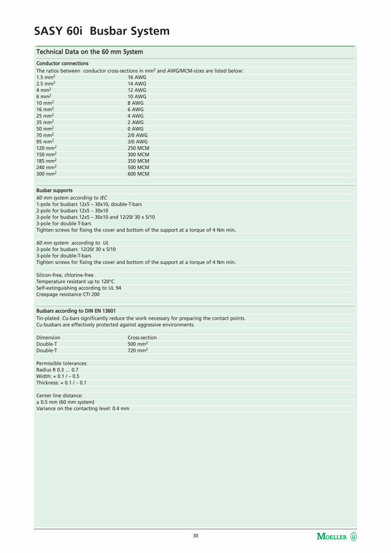
Technical DData oon tthe 660 mmm SSystem
Conductor cconnections The ratios between conductor cross-sections in mm2 and AWG/MCM-sizes are listed below:1.5 mm2 16 AWG2.5 mm2 14 AWG4 mm2 12 AWG6 mm2 10 AWG10 mm2 8 AWG16 mm2 6 AWG25 mm2 4 AWG35 mm2 2 AWG50 mm2 0 AWG70 mm2 2/0 AWG95 mm2 3/0 AWG120 mm2 250 MCM150 mm2 300 MCM185 mm2 350 MCM240 mm2 500 MCM300 mm2 600 MCM
Busbar ssupports60 mm system according to IEC1-pole for busbars 12x5 – 30x10, double-T-bars2-pole for busbars 12x5 – 30x103-pole for busbars 12x5 – 30x10 and 12/20/ 30 x 5/103-pole for double-T-barsTighten screws for fixing the cover and bottom of the support at a torque of 4 Nm min.
60 mm system according to UL3-pole for busbars 12/20/ 30 x 5/103-pole for double-T-bars Tighten screws for fixing the cover and bottom of the support at a torque of 4 Nm min.
Silicon-free, chlorine-free Temperature resistant up to 120°CSelf-extinguishing according to UL 94Creepage resistance CTI 200
Busbars aaccording tto DDIN EEN 113601Tin-plated Cu-bars significantly reduce the work necessary for preparing the contact points. Cu-busbars are effectively protected against aggressive environments.
Dimension Cross-sectionDouble-T 500 mm2
Double-T 720 mm2
Permissible tolerances:Radius R 0.3 … 0.7Width: + 0.1 / – 0.5Thickness: + 0.1 / – 0.1
Center line distance:± 0.5 mm (60 mm system)Variance on the contacting level: 0.4 mm

31
SASY 60i Busbar System
Technical DData oon tthe 660 mmm SSystem
Busbars aaccording tto DDIN EEN 113601The UL 508A standard limits the permissible current density for busbars to a value of 1000 A / inch2 (1.55 A /mm2). The higher current carrying capacities to DIN 43671 were obtained under operating conditions. The busbar temperature is normally positively influenced by mounting components on the busbar and by air circulation within the installa-tion.
Depending on the respective ambient temperature, you can calculate the correction factor k2 according to DIN 43 671 for flat busbars. Ifambient conditions change, a correction factor needs to be taken into account.On the other hand, increased loads may occur if the components feature a correspondingly high temperature resistance. A 30 x 10 tin-plated busbar can under normal conditions be loaded with 630 A . With a load of 800A, for instance, a k2 correction factorof 1.3 is necessary. If follows from the diagram that with this factor and 35° C air temperature, the busbar heats up to approx. 85°C.
Base pplate Silicon-free, chlorine-free Temperature resistant up to 110°CSelf-extinguishing according to UL 94
Busbar ccoversfor busbars of 12 x 5, 12–30 x 5, 12–30 x 10Double-T-Profiles
Silicon-free, chlorine-free Temperature resistant up to 110°CSelf-extinguishing according to UL 94
Modular ssystem ccoverto be attached to 60 mm systems, 3-poleto busbars of 12/20/30 x 5/10, 25 x 5,to double-T-profiles
Cover profile frontCover profile top/bottomCover profile support
Silicon-free, chlorine-free Temperature resistant up to 120°CSelf-extinguishing according to UL 94
32
SASY 60i Busbar System
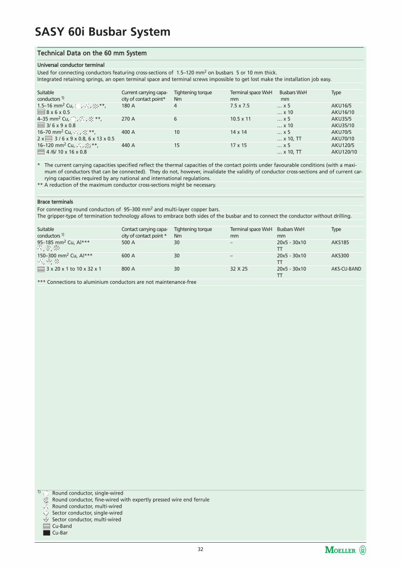
Technical DData oon tthe 660 mmm SSystem
Universal cconductor tterminalUsed for connecting conductors featuring cross-sections of 1.5–120 mm2 on busbars 5 or 10 mm thick. Integrated retaining springs, an open terminal space and terminal screws impossible to get lost make the installation job easy.
Suitable Current carrying capa- Tightening torque Terminal space WxH Busbars WxH Typeconductors 1) city of contact point* Nm mm mm1.5–16 mm2 Cu, , , **, 180 A 4 7.5 x 7.5 … x 5 AKU16/5
8 x 6 x 0.5 … x 10 AKU16/104–35 mm2 Cu, , , **, 270 A 6 10.5 x 11 … x 5 AKU35/5
3/ 6 x 9 x 0.8 … x 10 AKU35/1016–70 mm2 Cu, , **, 400 A 10 14 x 14 … x 5 AKU70/52 x 3 / 6 x 9 x 0.8, 6 x 13 x 0.5 … x 10, TT AKU70/1016–120 mm2 Cu, , **, 440 A 15 17 x 15 … x 5 AKU120/5
4 /6/ 10 x 16 x 0.8 … x 10, TT AKU120/10
* The current carrying capacities specified reflect the thermal capacities of the contact points under favourable conditions (with a maxi-mum of conductors that can be connected). They do not, however, invalidate the validity of conductor cross-sections and of current car-rying capacities required by any national and international regulations.
** A reduction of the maximum conductor cross-sections might be necessary.
Brace tterminalsFor connecting round conductors of 95–300 mm2 and multi-layer copper bars.The gripper-type of termination technology allows to embrace both sides of the busbar and to connect the conductor without drilling.
Suitable Contact carrying capa- Tightening torque Terminal space WxH Busbars WxH Typeconductors 1) city of contact point * Nm mm mm95–185 mm2 Cu, Al*** 500 A 30 – 20x5 - 30x10 AKS185
, , TT150–300 mm2 Cu, Al*** 600 A 30 – 20x5 - 30x10 AKS300
, , TT3 x 20 x 1 to 10 x 32 x 1 800 A 30 32 X 25 20x5 - 30x10 AKS-CU-BAND
TT*** Connections to aluminium conductors are not maintenance-free
1) Round conductor, single-wired Round conductor, fine-wired with expertly pressed wire end ferruleRound conductor, multi-wiredSector conductor, single-wired Sector conductor, multi-wired Cu-BandCu-Bar

33
SASY 60i Busbar System
Technical DData oon tthe 660 mmm SSystem
Connecting tterminal pplates Incl. cover cap
50, 120 mm2
3-pole, 690 V~Centre line distance of bars 60 mmBusbars … x 5 – 10,Double-T-profiles
Terminal plates:Silicon-free, chlorine-freeTemperature resistant up to 120°CSelf-extinguishing according to UL 94Creepage resistance CTI 200
Cover cap:Silicon-free, chlorine-free Temperature resistant up to 120°CSelf-extinguishing according to UL 94
Suitable Current carrying capa- Tightening torque Terminal space WxH Busbars WxH Typeconductors 1) city of contact point * Nm mm mm6 –50 (70) mm2 Cu, , **, 300 A 8 - 10 10 x 15 … x 5 – 10 BBA-TP3/50
6 x 9x 0.8 TT35 –120 mm2 Cu, , **, 440 A 12 - 15 15 x 15 … x 5 – 10 BBA-TP3/120
6 / 10 x 16 x 0.8 TT
Connecting sset, 33-ppoleIncl.cover cap
300 mm2, 10 x 32 x 11-pole, 690 V~Centre line distance of bars 60 mmBusbars 20x5 - 30x10Double-T-profiles
Suitable Current carrying capa Tightening torque Terminal space WxH Busbars WxH Typeconductors city of contact point * Nm mm mm120–300 mm2 Cu, Al***, 560 A 30 20x5 - 30x10 BBA-TP3/300
, , , TT3 x 20 x 1 to 10 x 32 x 1 800 A 30 32 x 25 20x5 - 30x10 BBA-TP3/CUBAND
TT
** It might be necessary to reduce the maximum conductor cross sections.*** Connections to aluminium conductors are not maintenance-free.
1) Round conductors, single-wiredRound conductors, fine-wired with expertly pressed wire end ferrulesRound conductors, multi-wired Sector conductors, single-wired Sector conductors, multi-wired Cu-BandCu-Bar

34
SASY 60i Busbar System
Technical DData oon tthe 660 mmm SSystem
Busbar cconnecting tterminalFor lenghtwise connection of identically shaped busbars without drilling
Current carrying capa- Overall length Permissible mis- Tightening torque Spacing between Typecity of contact point mm alignment of bars Nm systems in mm630 A 150 1 mm 12 100 - 110 BBT-CU12-20X5/10-150630 A 95 5 mm 20 50 - 60 BBT-CU20-30X5/10-95630 A 150 5 mm 30 100 - 110 BBT-CU20-30X5/10-1501600 A 50 2 mm 20 9 -20 BBT-CU-BAR500/720-501600 A 150 5 mm 20 100 - 110 BBT-CU-BAR500/720-150
Profile tterminals ffor ddouble-TT-bbars
Current carrying capa- Profile Terminal space W x H Tightening torque Typecity of contact point (without spacers) Nm1600 A TT 41 x 20 – 42 40 AKP8001600 A TT 51 x 20 – 42 40 AKP1000
Use spacers provided when two multi-layer CU-BAND types of copper busbars are connected in parallel.
xStart bbusbar aadaptor
3-pole, 690 V~Can be used on all busbars in a 60 mm system.Thanks to the combi-base it is suitable for a thickness of both 5 and 10 mm. DIN EN 60715 support rail, plastic, can be adjusted on a 1.25-mm grid.Copper conductors are ultrasound welded.
Base body:Silicon-free, chlorine-free Temperature resistant up to 120°CSelf-extinguishing according to UL 94Creepage resistance CTI 200
Support rails:Silicon-free, chlorine-free Temperature resistant up to 100°CPVC conductor insulation: Temperature resistant up to 105°C
Busbar aadaptor NNZM
Parameter NZM1-XXAD160 NZM2-XXAD250 NZM3-XXAD550Design 3-pole, 690 V~ 3-pole, 690 V~ 3-pole, 690 V~Bar system 60 mm 60 mm 60 mmBar contacting combi-base claw-type terminal claw-type terminalTightening torque at bar - 8 12Tightening torque of tube connection - 8 40Connection of the switchgear top top or bottom top
NZM1-XXAD160Base body:ThermoplastTemperature resistant up to 120°CSelf-extinguishing according to UL 94Creepage resistance CTI 200Halogen-freeConductor insulation:PVC,Temperature resistant up to 105 °C
NZM2-XXAD250Base body:ThermoplastTemperature resistant up to 120°C,Self-extinguishing according to UL 94,Creepage resistance CTI 200,Halogen-free
NZM3-XXAD550Base body:ThermoplastTemperature resistant up to 120°C,Self-extinguishing according to UL 94,Creepage resistance CTI 200,Halogen-free

35
SASY 60i Busbar System
Dimensions
BBS-3/FL
ES-BBS-3/FL
BBS-3/FL-NA
BBS-2/FL

36
SASY 60i Busbar System
Dimensions
BBS-1/FL
BBS-1/PR
BBS-3/PR
ES-BBS-3/PR
BBC-BT-NA

37
SASY 60i Busbar System
Dimensions
CU-BAR-500/T
BBC-CU-BAR/PR
CU-BAR-720/T
BBC-RCOV1
BBC-CS2-F + BBC-CS2-T/B + BBC-MCS2 BBC-CS48/PR

38
SASY 60i Busbar System
Dimensions
BBC-CS76/PR
BBA-TP3/120
BBA-TP3/50
BBA-TP3/300
BBA-TP3/CU-Band AKS185

39
SASY 60i Busbar System
Dimensions
AKS300
AKP1000
AKS-CU-BAND
AKU 16/5
AKU 35/5 AKU 70/5

40
SASY 60i Busbar System
Dimensions
AKU 120/5
AKU 35/10
AKU 16/10
AKU 70/10
AKU 120/10 BBT-CU20-30X5/10-95

41
SASY 60i Busbar System
Dimensions
BBT-CU20-30X5/10-150
BBT-CU-BAR500/720-150
BBT-CU-BAR500/720-50
BBT-CU12-20x5/10-150

42
SASY 60i Busbar System
Dimensions
NZM1-XAD160
NZM2-XAD250

43
SASY 60i Busbar System
Dimensions
NZM3-XAD550

44
SASY 60i Busbar System
Dimensions
GST00-160-40-60-AOU
GST-.-AO / GST-.-AU
TTyyppee SS TT UU
GST00-160-40-60-AOU 40 12 5-1050 20 5-1560 20-30 5-10
TTyyppee AA BB CC DD EE FF GG HH KK
GST1-A. 184 230 322 70 121 16,5 115 104 58GST2-A. 210 256 408 83 135 16,5 128 145 66GST3-A. 254 270 434 98 149 9 135 156 82
LTS-100/C00/3-R
D02-S/63/3-RS
D...SO/.../3-R
TTyyppee AA
D02-SO/63/3-R 27DII-SO/25/3-R 45DIII-SO/63/3-R 54

45
SASY 60i Busbar System
UL/CSA AApprovals LList
Article NNo. Type DDesignation
USA 1) Canada104554 NZM1-XAD160104555 NZM2-XAD250104556 NZM3-XAD550101451 BBA0-25101452 BBA0-32101453 BBA0R-25101454 BBA0R-32101455 BBA0C-16101456 BBA0RC-16101457 BBA4-63101458 BBA2-63101459 BBA4L-63101480 BBA2L-63101481 BBA0-25/2TS101482 BBA0/2TS-L101483 BBA4/2TS-L101484 BBA-XSM107066 BBS-3/FL107067 BBS-3/FL-NA107068 ES-BBS-3/FL107162 BBS-3/PR107164 ES-BBS-3/PR107165 BBS-1/PR107166 CU-BAR-500/T107167 CU-BAR-720/T107172 BBC-BT-NA107173 BBC-FL5107174 BBC-FL10107175 BBC-CU-BAR/PR107178 BBC-RCOV1107179 BBC-MRCOV1107180 BBC-CS2-F107181 BBC-CS2-T/B107182 BBC-MCS2107183 BBA-TP3/50107184 BBA-TP3/120107185 BBA-TP3/300107186 BBA-TP3/CU-BAND107187 AKU16/5107188 AKU35/5107189 AKU70/5107190 AKU120/5107191 AKU16/10107192 AKU35/10107193 AKU70/10107194 AKU120/10107195 AKS185107196 AKS300107197 AKS-CU-BAND107198 AKP800107199 AKP1000
1) Tested for feeder circuits according to UL-508A up to 600 V
UL-Approbation File No: E307559, E300273CSA-Approbation Report No: 236217, 232140UL File No. for CU-Band: E248096

46
SASY 60i Busbar System
Copper WWeight
Article NNo. TType DDesignation Cu-NNumber 1)
107166 CU-BAR-500/T 10.44 107167 CU-BAR-720/T 15.40 107183 BBA-TP3/50 0.03 107184 BBA-TP3/120 0.05 107198 AKP800 0.20 107199 AKP1000 0.23 107201 BBT-CU20-30X5/10-95 0.48 107202 BBT-CU20-30X5/10-150 0.76 107203 BBT-CU-BAR500/720-50 0.24 107204 BBT-CU-BAR500/720-150 0.79 104554 NZM1-XAD160 0.23 104555 NZM2-XAD250 0.32 104556 NZM3-XAD550 1.11 81167 CU-BAND3X9X0,8-BK 0.4180960 CU-BAND3X9X0,8-BU 0.4181006 CU-BAND3X9X0,8-GNYE 0.4181414 CU-BAND6X9X0,8-BK 0.8381344 CU-BAND6X9X0,8-BU 0.8381367 CU-BAND6X9X0,8-GNYE 0.8381515 CU-BAND9X9X0,8-BK 1.2481436 CU-BAND9X9X0,8-BU 1.2481485 CU-BAND9X9X0,8-GNYE 1.2481310 CU-BAND6X16X0,8-BK 1.4381222 CU-BAND6X16X0,8-BU 1.4381275 CU-BAND6X16X0,8-GNYE 1.4380739 CU-BAND10X16X0,8-BK 2.3879736 CU-BAND10X16X0,8-BU 2.3880698 CU-BAND10X16X0,8-GNYE 2.3880923 CU-BAND11X21X1-BK 4.4480769 CU-BAND11X21X1-BU 4.4480836 CU-BAND11X21X1-GNYE 4.44284690 LTS-100/C00/3-R 0.22 224550 GST00-160-40-60-AOU 0.23 107250 GST1-AO 1.08 107251 GST1-AU 1.12 107252 GST2-AO 1.61 107253 GST2-AU 1.63 107254 GST3-AO 2.42 107255 GST3-AU 2.42 284649 D02-S/63/3-RS 0.08 107964 D02-SO/63/3-R 0.04 101451 BBA0-25 0.03 101452 BBA0-32 0.05 101453 BBA0R-25 0.03 101454 BBA0R-32 0.05 101455 BBA0C-16 0.03 101456 BBA0RC-16 0.03 101457 BBA4-63 0.12 101458 BBA2-63 0.12 101459 BBA4L-63 0.12 101480 BBA2L-63 0.12 101481 BBA0-25/2TS 0.03
1) Extra ccharges
In the event of any significant increase in raw material prices (like of aluminium, copper, silver, plastic, steel), an extra charge for materialmight be invoiced where necessary. In case of exceeding the price limit of Euro 150.00/100kg according to the copper quotation (DEL-Notiz = Deutsche Elektrolyte Kupfer Notiz) and the aluminium quotation for processed metal and conducting aluminium, we will add anextra charge for material in euros, net, according to the quotation of the day we receive the order:Copper:DEL-Notiz – Euro 150.00
100
Aluminium:Al-quotation – Euro 150.00
100
x Cu-Number
x Al-Number

47
Notes
Notes

48
Notes
Notes
We keep power under control.
www.moellerhome.net
We keep power under control.
Product Catalogue 2006/2007
SASY 60i valid from Oktober 2006Moeller GmbH
Hein-Moeller-Str. 7-11D-53115 Bonn
E-Mail: [email protected]: www.moeller.net
© 2007 by Moeller GmbHSubject to alterationFK4300-1167 GB (04/07)Printed in Austria (04/07)Grafic: Werbeweber, SchremsDigiPics, Lithos: Jonas, HeidenreichsteinDruck: Rabl, SchremsArticle No.
With Xclever home, Moeller offers the completeelectrical installation from one source for a safeand easily controllable building. All Xclever homeproduct groups stand out because of their highsafety standards and simple and easy application.
Combines all functional and assembly safety advantages. From circuit-breakers and modular installation devices to over-voltage protection.
The complete distribution program for safe electrical installations from 63 to 2500 Amps. For houses, blocks of flats or functional buildings.
Covers all requirements of operation in buildings. The system opens new business possibilities for new and renovated buildings.
A clever, complete range that can be flexibly extended for the installation of future-orientated data networks.
GermanyInternet: www.moeller.net
BerlinMoeller Electric GmbHMoeller Haus BerlinUllsteinstraße 8712109 Berlin Tel. (0 30) 70 19 02-0Fax (0 30) 70 19 02-39E-Mail: [email protected]
Düsseldorf Moeller Electric GmbHMoeller Haus DüsseldorfIm Taubental 3241468 Neuss Tel. (0 21 31) 3 17-0Fax (0 21 31) 3 17-2 76E-Mail: [email protected]
FrankfurtMoeller Electric GmbHMoeller Haus FrankfurtBerner Straße 11160437 Frankfurt Tel. (0 69) 5 00 89-0 Fax (0 69) 5 00 89-2 70E-Mail: [email protected]
Hamburg Moeller Electric GmbHMoeller Haus HamburgGeorgswerder Bogen 321109 Hamburg Tel. (0 40) 7 50 19-0 Fax (0 40) 7 50 19-2 69E-Mail: [email protected]
MünchenMoeller Electric GmbHMoeller Haus MünchenWernher-von-Braun-Straße 585640 Putzbrunn Tel. (0 89) 4 60 95-0 Fax (0 89) 4 60 95-2 67E-Mail: [email protected]
StuttgartMoeller Electric GmbHMoeller Haus StuttgartSchelmenwasenstraße 3270567 Stuttgart Tel. (07 11) 6 87 89-0 Fax (07 11) 6 87 89-99E-Mail: [email protected]
SASY 60i the consistent,
UL-certified solution for power
distribution and for switching,
controlling and protecting your
equipment.
A space-saving desing ideal for
mechanical and systems
engineering.
Metering boards
CompactDistribution Boxes
Flat DistributionBoards
InstallationDistribution Boards
Add-on DistributionBoards
Accessories