SARADAR PATEL VIDYUT BHAVAN, - Welcome to GUVNL Office/01022011/030620… · gujarat energy...
27
GUJARAT ENERGY TRANSMISSION CORPORATION LTD. SARADAR PATEL VIDYUT BHAVAN, RACE COURSE, BARODA – 390 007. TECHNICAL SPECIFICATIONS FOR CIVIL WORKS FOR GIS GETCO/C/TS-Civil Works for GIS-050 /R2/ March 11 GETCO/C/TS/Civil Works for GIS- 050 R2 Dt.08-03-2011 Page 1 of 27
Transcript of SARADAR PATEL VIDYUT BHAVAN, - Welcome to GUVNL Office/01022011/030620… · gujarat energy...

GUJARAT ENERGY TRANSMISSION CORPORATION LTD.
SARADAR PATEL VIDYUT BHAVAN,RACE COURSE, BARODA – 390 007.
TECHNICAL SPECIFICATIONSFOR
CIVIL WORKS FOR GIS
GETCO/C/TS-Civil Works for GIS-050 /R2/ March 11
GETCO/C/TS/Civil Works for GIS- 050 R2 Dt.08-03-2011 Page 1 of 27

TECHNICAL SPECIFICAITONS OF CIVIL WORKS FOR GIS s/s The scope of work under this contract shall include design and construction of all the items mentioned hereunder, but not limited to, which are required for satisfactory & successful completion and commissioning of GIS Sub-station at place in the state of Gujarat. The exact place is mentioned elsewhere in tender document.
1.0 GENERALThe intent of specification covers the following.
Design, engineering & construction of all civil works at sub-station. All civil works shall also satisfy the general technical specifications specified in other sections of this specification as detailed below. Civil works shall be designed to the service conditions / loads as specified elsewhere in this specification or as implied as per National / International standards.The building and all civil works will be provided as per recommendation from the manufacturer. Special attention shall be given to an optimized design with small space requirements and therefore the bidder input is essential. An overhead crane will be supplied for installation and maintenance work. The bidder shall specify the lifting height and capacity necessary for lifting of the heaviest peace during installation of maintenance. All civil, structural and architectural works shall be designed, provided and constructed as per latest editions of Indian Codes and Standards with addendums and supplements as issued by ISI. Wherever Indian Standards are not available/formulated, applicable BS or international standards shall be used. In case of ambiguity between codes, specifications and drawings, the most stringent of them shall govern. The contractor shall provide all design, drawings, labour, tools, equipments, material, temporary works, construction plants & machinery, fuel supply, transportation and all other incidental items not specified but as they may be required for complete performance of the works in accordance with approved drawings, specifications & direction of the GETCO.The work shall be carried out according to design & drawings to be developed by the contractor and approved by GETCO based on the tender drawings specified by GETCO to the contractor. For all buildings ,structures, foundations etc. necessary layout & details shall be developed by the contractor keeping in view the functional requirement of the substation, required facilities & providing enough space to access for operation, use & maintenance based on the inputs provided by GETCO. Certain minimum requirements are indicated hereunder for guidance purpose only. However, contractor shall quote the rates according to the complete system requirements.All the design and drawings shall be submitted in five set of hard copy and two set of soft copy. Drawing shall be submitted in ‘AutoCAD’ format. Submitted design and drawings will be property of GETCO. Also design basis document for civil and architectural work shall be submitted for approval. 3D model based on architectural drawing with all possible views shall be prepared and submitted.
GETCO/C/TS/Civil Works for GIS- 050 R2 Dt.08-03-2011 Page 2 of 27

All the work shall be strictly executed as per FIELD QUALITY PLAN approved by GETCO which is shown as ANNEXTURE ‘B’ & Approved technical specification of GETCO for civil works.
2.0 The scope of work under this contract shall include following.1. Site Preparation2. GIS and Control room building with crane arrangement and
cable cellar. (Basement + GF + FF)3. Security Cabin.4. Foundations for Switch Yard Structures & Equipments5. Cable Trenches & Earthing Chambers6. Transformer Foundations with marshalling work & its track
up-to road7. Transformer Oil Sumps with necessary piping.8. Fire Protection Wall 9. Roads, Culverts, Paving & Storm water Drains 10. Bore wells11. Water Supply System internal & external with (U/G + OH
tanks)12. Chain link Fencing with Gate13. Septic Tank with Soak Pit and drainage system (Internal &
External) 14. Car / Scooter Parking Sheds.15. Metal spreading with micro-levelling & anti-weed treatment16. Rain Water Harvesting.17. Tree Plantation – (Green Belt) & Horticultural Work18. Furniture, RO Plant for potable water, Water Coolers, Mini
Conference Table etc.19. Specific Requirement20. Any other civil work that is required for successful
completion & commissioning of 66kv GIS Sub-station.
(1) Site Preparation: Levelling of the plot area (i.e) grading prior to EPC contractor commencing work in plot boundary area, will be done by others to a formation level of approx. R.L. as per site sketch and Boundary wall constructed. The final grading to the required finished level, with slopes to drainage system final landscaping etc. shall be done by the bidder as per approved Construction Drawings. Water supply system, Storm water drainage system, Sewage system, Septic Tank and disposal system shall be
GETCO/C/TS/Civil Works for GIS- 050 R2 Dt.08-03-2011 Page 3 of 27

designed and constructed by the bidder. The drainage and treated effluent from the plot area shall be disposed up to disposal point (outside) including development of drain beyond disposal point.
(2) 66kV GIS & Control Room Building (as per scope of the Tender):
GIS & Control Room Building shall be RCC Framed Structure having BASEMENT + GF + FF. Basement shall be made of RCC retaining wall and Room for electrical installations must be designed such that no water can penetrate and such that condensation is kept to a minimum. The details of the same are as under.
NAME OF FLOOR FUNCTIONAL PURPOSE CARPET AREA ( m2 )
BASEMENT CELLAR (Cables Accommodation) 304
GROUND FLOOR66kV GIS Room 112
30111kV Panels Room and other rooms 189
FIRST FLOORCRP & SCADA, LVAC/DC, Meeting room
189
The walls in the building shall be non-load bearing in-filled panel walls. All external and internal walls will be of CC block except partition walls in the toilet area where it will be brick masonry (115mm thk.). All the walls shall be supported on RCC wall beams and plinth beams such that unsupported length is not more than about 3m. The walls shall be laid in 1:4 cement: sand mortar.- The Finished Floor level of the Building shall be EL(+)1.0 m.
- The external wall surfaces will be provided with 20 mm thick plaster in two layers, with exterior Acrylic Paint (Apex or Equivalent). Internal plastering will be of 12 mm thick in 1:3 cement mortars. Ceiling in areas where false ceiling is not provided will be given ceiling plaster 12 mm thick.
- 50mm thick Damp Proof Course (DPC) shall be provided at plinth level before starting the masonry work. The DPC shall be in PCC M20 grade with water proofing compound followed by two layers of bitumen coating 85/25 grade as per IS 702.
- Height of skirting above finished floor level shall be 150mm.
Parapet wall
The parapet wall over the building shall be 900mm high from the finished roof level.Plinth Protection
Entire area around the Control room building shall be provided with M20 grade PCC paving of minimum 100 mm thickness over consolidated/compacted earth, starting from the building edge up to 750mm clear distance for the full length of the building.Roof / Floor Finishes GETCO/C/TS/Civil Works for GIS- 050 R2 Dt.08-03-2011 Page 4 of 27
Roof FinishThe water proofing treatment of RCC slab roof of building shall consist of the following operations: (a) The roof shall be provided with China Mosaic flooring water proofing.
(b) For sufficient disposal of rain water, the run-off gradient for the roof shall not be less than 1:200. Screed concrete of M20 grade or cement sand mortar 1:3 shall be used to provide the gradient. The rain water down comers shall be of uPVC conforming to IS- 4985. The number and size of down-comers shall be governed by IS -1742 and IS- 2527.Rainwater pipes from roof shall be fixed on the outside face of the column and encased later with concrete.
Floor FinishFloor finishing schedule of GIS & Control room building shall be as per Annexure – A.Doors and windows1. All the windows and ventilators of building shall be of anodised aluminium. Main entrance shall have aluminium framework with glazing. Doors shall be of swing type. 2. WC/ toilets shall be single leaf PVC door.3. For aluminium door the aluminium section to be utilized shall confirm to IS 1285/1980 and IS 1869/1968 for the material grade and anodizing respectively. The frame section shall be of standard size and as directed by Engineer-in-charge. Minimum of section no 8687 Jindal Aluminium Ltd. Make or its equivalent and section for shutter shall be of standard size. Minimum of section No 8305 of Jindal aluminium Ltd. Make or its equivalent. Necessary additional / special sections shall be used to facilitate locking arrangement, handle stay if necessary as directed by EIC. For aluminium window and ventilator the aluminium section to be utilized shall confirm to IS 1285/1980 and IS 1869/1968 for the material grade and anodizing respectively. The frame section shall be 61.85mm x 31.75mm weighing 0.695kg per mtr. Minimum of section No 8687 Jindal Aluminium Ltd. Make or its equivalent and section for shutter shall be of 50 mm x 20 mm size weighing 0.571kg per Mtr. Minimum of section No 8305 of Jindal aluminium Ltd. Make or its equivalent. Necessary additional / special sections shall be used to facilitate locking arrangement, handle stay if necessary as directed by EIC.4. Rolling shutters with manual operating arrangement according to size shall be provided in GIS room (Control Room Building) to facilitate handling and transportation of dry type transformer. 5. All doors/shutters/windows shall be provided with all standard accessories such as handles, tower bolts, locks, stoppers, floor mounted spring type door closure etc. of best quality as approved by the Employer.Glazing and its thickness1. Minimum thickness of glazing shall be 6.0 mm. Glazing shall have fire rating of minimum 1 hour.False ceilingThe Luxalon/ Interarch False ceiling shall be provided in all air- conditioned area.
GETCO/C/TS/Civil Works for GIS- 050 R2 Dt.08-03-2011 Page 5 of 27

Toilet details including plumbing and sanitation-Two toilets, one for gents and other for ladies, shall be provided in the building.-Galvanized MS pipe of medium class conforming to IS-1239 shall be used for internal piping works for potable water supply. -uPVC pipes conforming to IS: 4985 shall be used for sanitary works above ground level. - A shaft shall be provided in the Toilet Area for water supply, soil and vent pipes. -Each toilet shall have the following minimum fittings: a) WC (Western type) 390mm high with toilet paper roll holder and all fittings. b) Urinal (430x260x350 mm size) with all fittings (Fully sealed).c) Wash basin (550x440 mm) with all fittings (Fully sealed).d) Bathroom mirror (600x450x5.5mm thick). e) CP brass towel rail (600x20mm) f) Soap holder Projection over doors and windows:Doors and windows on external walls buildings shall be provided with RCC sun-shade over the openings. Projection of sunshade from the wall shall be minimum 450 mm over window openings and 450 mm over door openings.
(3) Security Cabin:Security Cabin shall be constructed with approximate size of 3.00 mtr x 3.00 mtr. near main gate having toilet block with RCC structure & slab as per approved design and drawing.
(4) Foundation for Switch Yard Structures & Equipments:The foundations for switch yard Structures & equipments shall be constructed as per approved layout plan of switch yard. Major structural & equipment foundations shall be cast in RCC minimum grade M20. The TOC shall be 300 mm above FGL unless otherwise specified. The grouting of foundation bolts shall be done GP-2 non-shrink type material.Equipment foundations shall be analysed for all possible load combinations both static and dynamic, wherever applicable. However, if the dynamic load component is very less when compared to static loads and or if the requirement of plinth / pedestal size is more, then static analysis will be adopted by considering 3 times the static weight of the equipment.
(5) Cable trenches:Cable trench shall be constructed as per approved drawing with RCC walls and RCC precast covers with edge protection angles of size 50x50x6 mm. The cable trays shall be fabricated with structural steel and fixed with vertical walls of cable trench with suitable grouting or with anchor bolts. The cable trays shall be applied with one coat of red-oxide & three coats of oil paint of approved brand & shade.All cable trench bed shall have slope of 1/500 along the run and 1/250 perpendicular to the run. All the construction joints of cable trenches i.e. between base slab to base slab, the junction of vertical wall to base slab from vertical wall to wall and all the expansion joints shall be provided with approved quality PVC water stops of approximately 230 x 6 mm size for those sections where the ground water table is expected to rise above the junction of base slab and vertical
GETCO/C/TS/Civil Works for GIS- 050 R2 Dt.08-03-2011 Page 6 of 27
wall of cable trenches. Cable trenches shall be blocked at the ends if required with RCC wall.
(6) Transformer Foundations with marshalling work & its track up-to road:
This shall be provided as per approved drawing with RCC M20 grade of concrete. The guide rail as per drawing shall be grouted in the foundation. The marshalling arrangement with rail shall be provided up-to the road.Transformer foundations shall be analysed for all possible load combinations both static and dynamic, wherever applicable. However, if the dynamic load component is very less when compared to static loads and or if the requirement of plinth / pedestal size is more, then static analysis will be adopted by considering 3 times the static weight of the equipment. A rail cum road system integrated with the transformer foundation to enable installation and the removal of any failed unit shall be provided. The Rail cum Road shall have RCC type foundation.This work includes radiator bank and other foundations required for commissioning of transformer successfully.
(7) Transformer Oil Sump with piping:This shall be provided as per approved drawing with RCC M20 grade of concrete with all piping arrangement.Transformer oil sump shall be designed for 20000 litre capacity with all systems and arrangement required to collect the oil in sump etc required for complete satisfaction of EIC and as per latest prevailing practices for oil sump.
(8) Fire Protection Wall:Fire Protection wall shall be provided as per design & drawing at locations marked in approved layout plan. The wall shall be of RCC construction with BB masonary & cement plaster finish. The height of wall shall be minimum 600mm more than the height of the bushing. The wall shall have a minimum fire resistance of 2 hours.
(9) Roads, Culverts, Paving & Storm water Drains: Main road of width 6.00 mtr shall be of RCC designed to IRC Standards. RCC paving of 1500 width for main road from entrance gate to front end of main Switchyard. Open storm water RCC rectangular drains will be provided on both sides of road or one side of the road as per the layout with RCC.The drains will have a longitudinal slope of 1 in 1000. Storm water drain crossing the roads shall be of RCC Hume pipe class NP2 with minimum 600mm sand cushion. Where sand cushion is not available, RCC encasement shall be provided. Also 300 dia. pipe class NP2 across the road shall be provided at suitable distance to pass the cables below road. Also, RCC garland drain around the control room and other building shall be provided with prestress covers. The prestresss cover shall be provided with edge protection angle. The storm water drain shall be provided with sufficient gradient and connected up to disposal point at approved location outside the battery limit. The quantity shall be measured in Running meter complied with the required specifications.
(10) Bore wells:
GETCO/C/TS/Civil Works for GIS- 050 R2 Dt.08-03-2011 Page 7 of 27

Bore well of minimum 200 mm dia. shall be provided by checking availability of water from Geologist including column pipes, providing submersible pump with all electrical accessories & ‘C’ class GI pipeline up to OHT & or UG Sump & commissioning the same.
(11) Water Supply System internal & external with (U/G + OH tanks):
Internal & external Water supply system with ‘C’ class GI pipeline for drinking water, service water & for earthing pits shall be provided.
(12) Chain link fencing with Gate:Chain link fencing & gate shall be provided as per drawing. The angle posts of fencing shall be rested on suitably designed foundations. The Grade of foundation shall be M20.
(13) Septic Tank with Soak Pit and drainage system (Internal & External):
Septic tank with soak pit for 50 users shall be provided with internal & external drainage system.
(14) Car / Scooter parking shed (If asked in the scope):Shed for six scooters and two cars with RCC structure shall be provided. The shed shall have RCC grade M20 flooring, beams, columns & slab with rain water draining arrangement.
(15) Metal spreading with micro-levelling & anti-weed treatment:The entire yard surfacing with 50 mm thick sand filling & 100 mm thick 20-30 mm size metal shall be provided after carrying out approved antiweed treatment.
(16) Rain Water Harvesting: Adequate rain water harvesting system shall be provided with all required sumps, drains & piping.
(17) Tree Plantation & Landscaping:The landscaping with flower beds at available places shall be provided. The tree plantation suitable to the prevailing environment in consultation with Horticulturist shall be provided.
(18) Furniture, RO Plant for potable water, Water Coolers, Mini Conference Table etc.:
Godrej or equivalent furniture for all the housing & other amenities as per scope shall be provided.
(19) Specific Requirement:Adequate fire protection measures must be taken between switchgear rooms and transformers and also between switchgear rooms and cable basements. After installation, ceiling and wall penetrations must be sealed in such a way that the fire prevention specifications applying to the building are fully complied with. In event of fire, escape routes, rescue routes and emergency exits must be usable and unobstructed.
GETCO/C/TS/Civil Works for GIS- 050 R2 Dt.08-03-2011 Page 8 of 27

(20) Any other civil work that is required for successful completion & commissioning of 66kv GIS Sub-station.
Codes & StandardsThe following Indian Codes and Standards shall generally be used for design of civil and structural works. In all cases, the latest revisions with amendments, if any, shall be followed.
SP: 6 ISI handbooks for structural engineers.IS: 2062 Specification for Structural Steel (Standard quality).IS: 456 Code of practice for plain and reinforced concrete.IS: 800 Code of practice for general construction in steel.IS: 806 Code of practice for use of steel tubes in general building
construction,IS: 808 Rolled steel beam, channel & angle sectionsIS: 813 Scheme of symbols for welding.IS: 816 Code of practice for use of metal arc welding for general
construction in mild steel.IS: 875 Code of practice for design loads (other than earthquake) for
buildings and structures.IS: 1038 Steel doors, windows and ventilators.IS: 1080 Code of practice for design and construction of shallow foundations
in soils (other than raft, ring and shell).IS: 1172 Code of basic requirements for water supply, drainage and
sanitation.IS: 1230 Cast iron rain water pipes and fittings. IS: 1346 Code of practice for water proofing of roofs with bitumen felts.IS: 1361 Steel windows for industrial buildings.IS: 1742 Code of practice for Building DrainageIS: 1893 Criteria for earthquake resistant design of structureIS: 1904 Code of practice for foundations in soil:-General requirementsIS: 1905 Code of practice for structural safety of buildingsIS: 2065 Code of practice for water supply in buildingsIS: 2074 Ready mixed paint, air drying, red oxide chrome, primingIS: 2212 Code of practice for brick workIS: 2470 Code of practice for installation of septic tankIS: 2527 Code of practice for fixing rain water gutters and down pipes for roof
drainageIS: 2911 Code of practice for design & construction of pile foundationIS: 2950 Code of Practice for design and construction of raft foundationsIS: 2974 Code of Practice for design and construction of machine
foundationsIS: 3067 Code of Practice for general design details for prepatory work for
damp proofing and water proofing buildingsIS: 3370 Code of Practice for concrete structures for the storage of liquidsIS: 3414 Code of Practice for design and installation of joints in buildingsIS: 3614 Fire check doors & TAC rulesIS: 4326 Code of Practice for earthquake resistant design and construction of
buildingsIS: 4971 Recommendations for selection of industrial floor finishesIS: 5624 Specification for Foundation bolts
GETCO/C/TS/Civil Works for GIS- 050 R2 Dt.08-03-2011 Page 9 of 27
IS: 8009 Code of Practice for calculation of settlement of foundations: (parts 1 & 2)
IS: 1829 Code practice for protection of iron and steel (Part I to III) structures for atmosphere corrosion
IS: 13301 Guidelines for design of flexible pavementsIS: 13920 Code practice for ductile detailing of reinforced concrete structure
subjected to seismic forceIRC: 37 Guide lines for design of flexible pavementsIRC: 73 Geometric designs of roadsDIN: 4024 Machine foundations: - Flexible supporting structures for machine
with rotating masses.SP 16 Design Aids for Reinforced Concrete to IS: 456-1978.
(A) Design Criteria The Soil investigation report furnished with tender document is for reference purpose only. The bidder has to conduct geotechnical investigation and decide on the various design parameters one proposes to adopt for foundation design. No commercial implications for any variations in this regard during execution shall be entertained for Soil Test Results as well as any of foundation design. All structures and portions thereof shall be analysed and designed to sustain various loads and combinations there of, conforming to the latest revision of applicable Indian Standards, Specifications, engineering practice and other technical requirements.. All structures shall be designed to sustain dead loads plus assigned live loads, impact load equipment, wind, seismic or other loads it is being subjected to.(A-1) Dead LoadsDead load shall include the weight of all structural components and architectural appurtenances incorporated in the structures plus hung loads and any other permanent, externally applied loads including equipment dead load.(A-2) Live LoadsLive load reductions as per provisions of IS: 875. Special use areas shall be investigated and loading revised upward as necessary. Hung loads shall be based on minimum loading equivalents of 100 Kgs. / Sqm. for piping and 50 Kgs/.Sqm. for electrical, ventilation and air conditioning. Loading due to concentrations of facilities in specific areas shall be considered.(A-3) Equipment Loadsa. Loads (both static and dynamic) of major equipment shall be considered as
per manufacturer's certified drawings. Equipment foundations shall be analysed for all possible load combinations both static and dynamic, wherever applicable. However, if the dynamic load component is very less compared to static loads and or if the requirement of plinth / pedestal size is more, then static analysis will be adopted by considering 3 times the static weight of the equipment.
b. Crane girders and supporting columns shall be designed for vertical and horizontal forces (including impact forces) as developed from the crane weights and wheel loads.
(A-4) Wind Loading
GETCO/C/TS/Civil Works for GIS- 050 R2 Dt.08-03-2011 Page 10 of 27

Wind loads shall be considered in accordance with Indian Standard Code IS: 875 for a basic wind speed of 50m/sec. up to height of 10 meters above mean ground level.
(A-5) Seismic LoadingSeismic Zone – V shall be considered as per latest IS: 1893. Importance factor of 1.5 shall be considered as per latest IS code.(A-6) Combination of Loads a. All structures shall be analyzed for the load combinations in accordance with the requirements of IS: 456 and IS: 875 for all possible combination of loads e.g. Dead load, live load, crane loads, wind or seismic loads, soil loads and surcharge loads. Appropriate allowable increase in permissible stresses as per IS codes, shall be taken except where as per above load combinations, load factors shall be used.(B) Cement & Concrete GradesThe cement shall be OPC / PPC cement for all civil works. The following minimum grades of concrete as per provisions of IS: 456 and other applicable codes shall generally be used for concrete structures(B-1) M-20: All reinforced concrete structures of Control Room, Fire water Pump house, important equipment foundations, structural concrete for foundation, super structure, reinforced concrete in Pavement, plinth protection etc (Min. cement consumption shall be 350 Kg. Per cmt of concrete). (B-2) M-10: Levelling course (Min. 100 mm thick) Below footings, Tanks, base slab for drains, fill concrete etc (Min. cement consumption shall be 225 kg. Per cmt of concrete.(C) Reinforcement: The reinforcing bars shall be TMT bars generally conform to various requirements of IS: 1786 (for High Strength deformed steel bars and wires for concrete reinforcement)
(D) Special requirements:
Excavation shall be carried out in all sort of soil for any depth and throwing away the extra stuff with in the lead of 2.0 KM radius and its dressing etc. Complete as directed by site in charge.
11kv Control room shall be provided with Luxalone / Interarch false ceiling. For the control room area, doors and windows shall be of anodised aluminium. Full glazing of 6 mm thick transparent float glass in anodised Aluminium Section frame work, from floor finish to false ceiling level, shall be provided in 11kv Control Room wall adjoining to operating floor.
Plinth level of all buildings shall be maintained at not less than 1000 mm above the plot formation level herein.
All CC Block / Brick work shall be CM (1:6) both faces of the brick work shall be plastered in CM. The inside plaster shall be finished in CM (1:3) with smooth cement Neeru Finish and outside shall be finished with sand faced plaster in two coats with cement mortar. The brick shall have min. compressive strength of 35 Kg / Cm2 for non load bearing wall.
All building shall be provided with U-PVC rain water down takes pipes, plinth protection and drainage system connected to main storm water drain. Plinth protection shall be in the form of 1000 mm wide and 100 mm thick (M20 grade) concrete laid over 230 mm thick rubble soiling, interstices filled
GETCO/C/TS/Civil Works for GIS- 050 R2 Dt.08-03-2011 Page 11 of 27
with small stone chips and sand. The air-conditioning system shall be provided for Control Room. The Luxanol / Interarch False Ceiling shall be provided in all air-conditioned area.
The Switch Yard area will be graded and covered with metal of size 40 to 60 mm. in layer of 100 mm thickness Also, the RCC path way shall be provided in Switch Yard as per the requirement. The transformer oil soak pit shall be filled with metal of size 40 to 60 mm in layer of 100 mm thickness. Plinth protection 1000mm wide shall be provided around all buildings. One PVC service water tank of 3m x 3m x 1m shall be provided on Control Room building./ GIS building. Suitable Plantation shall be done as directed within S/S premises.
GETCO/C/TS/Civil Works for GIS- 050 R2 Dt.08-03-2011 Page 12 of 27

ANNEXTURE - A
GETCO/C/TS/Civil Works for GIS- 050 R2 Dt.08-03-2011 Page 13 of 27
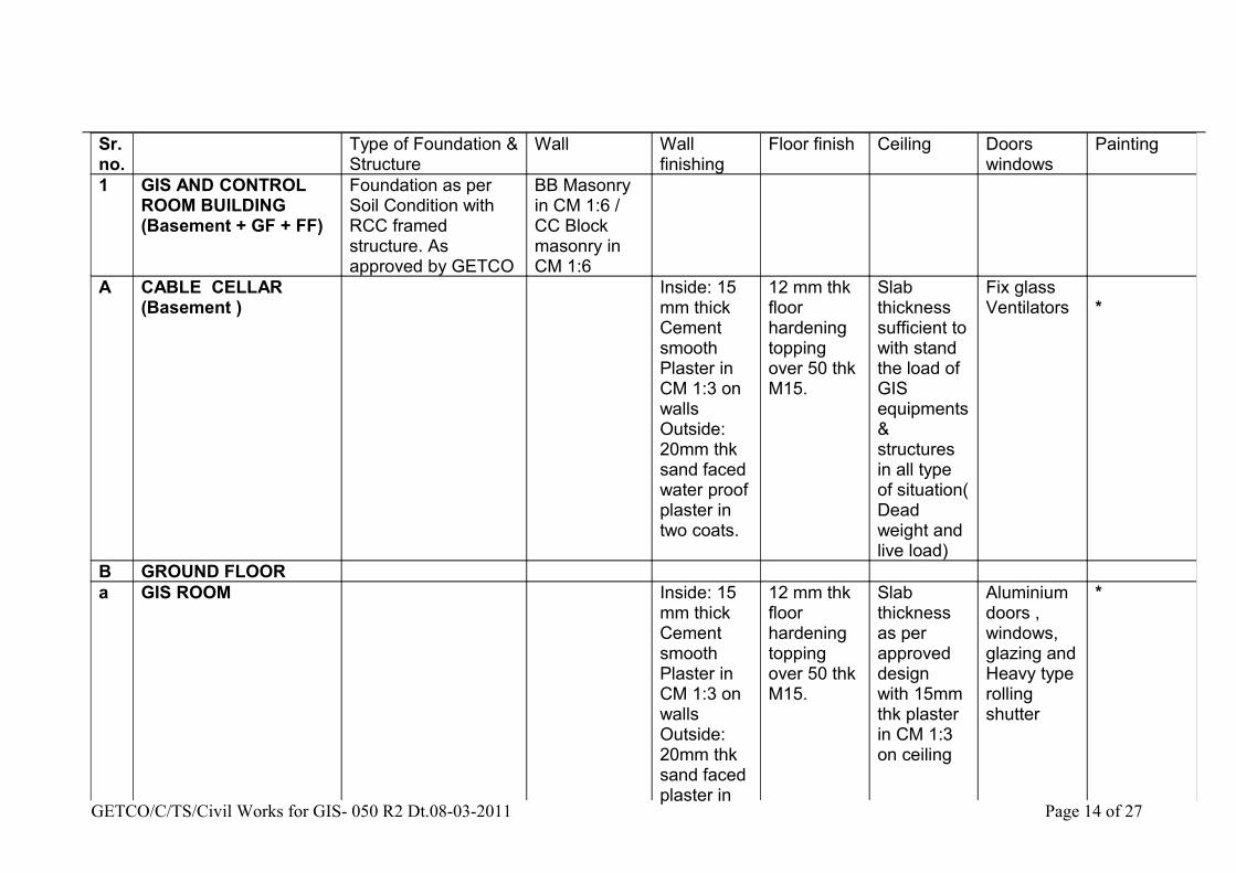
Sr. no.
Type of Foundation & Structure
Wall Wall finishing
Floor finish Ceiling Doors windows
Painting
1 GIS AND CONTROL ROOM BUILDING(Basement + GF + FF)
Foundation as per Soil Condition with RCC framed structure. As approved by GETCO
BB Masonry in CM 1:6 / CC Block masonry in CM 1:6
A CABLE CELLAR (Basement )
Inside: 15 mm thick Cement smooth Plaster in CM 1:3 on walls Outside: 20mm thk sand faced water proof plaster in two coats.
12 mm thk floor hardening topping over 50 thk M15.
Slab thickness sufficient to with stand the load of GIS equipments & structures in all type of situation( Dead weight and live load)
Fix glass Ventilators *
B GROUND FLOORa GIS ROOM Inside: 15
mm thick Cement smooth Plaster in CM 1:3 on walls Outside: 20mm thk sand faced plaster in
12 mm thk floor hardening topping over 50 thk M15.
Slab thickness as per approved design with 15mm thk plaster in CM 1:3 on ceiling
Aluminium doors , windows, glazing and Heavy type rolling shutter
*
GETCO/C/TS/Civil Works for GIS- 050 R2 Dt.08-03-2011 Page 14 of 27
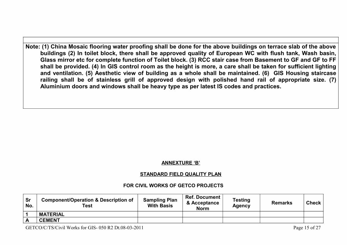
Note: (1) China Mosaic flooring water proofing shall be done for the above buildings on terrace slab of the above buildings (2) In toilet block, there shall be approved quality of European WC with flush tank, Wash basin, Glass mirror etc for complete function of Toilet block. (3) RCC stair case from Basement to GF and GF to FF shall be provided. (4) In GIS control room as the height is more, a care shall be taken for sufficient lighting and ventilation. (5) Aesthetic view of building as a whole shall be maintained. (6) GIS Housing staircase railing shall be of stainless grill of approved design with polished hand rail of appropriate size. (7) Aluminium doors and windows shall be heavy type as per latest IS codes and practices.
ANNEXTURE ‘B’
STANDARD FIELD QUALITY PLAN
FOR CIVIL WORKS OF GETCO PROJECTS
SrNo.
Component/Operation & Description ofTest
Sampling Plan With Basis
Ref. Document & Acceptance
NormTesting Agency Remarks Check
1 MATERIALA CEMENTGETCO/C/TS/Civil Works for GIS- 050 R2 Dt.08-03-2011 Page 15 of 27

(i)(ii)(iii)(iv)(v)
FinenessCompressive StrengthInitial & final setting timeSoundnessChemical Composition of Cement
As per mix Design requirement
IS: 456,IS: 269IS: 8112,IS: 12269IS: 1489
Govt.Approved Lab
The tests for cementCoarse aggregates &Fine aggregate shallbe conducted duringMix design for Concrete. Mix designshall be subject to approval by GETCO
B
B COARSE AGGREGATES(I)
(ii)(iii)(iv)(v)(vi)(vii)(viii)(ix
Determination of Particle size(Sieve Analysis)Flakiness IndexCrushing ValueSpecific GravityBulk DensityAbsorption ValueMoisture ContentSoundness of AggregatePresence of deleterious materials.
As per mix Design requirement
IS: 383,IS: 2386IS: 456
Govt.Approved Lab
In case of change of source of coarse & Fine aggregates, mix Design should be revised.
B
C FINE AGGREGATE
(I)
(ii)
(iii)
(iv)
(v)
(vi)
Gradation /Determination of Particle size
Specific Gravity and density.
Moisture content
Absorption Value
Bulking
Silt Content Test
As per mix Design requirement
IS: 383,IS: 2386,IS:456
B
GETCO/C/TS/Civil Works for GIS- 050 R2 Dt.08-03-2011 Page 16 of 27

(vii) Presence of deleterious materials
D BRICKS
(i)
(ii)
(iii)
(iv)
Dimensional tolerance
Compressive Strength Water Absorption
Efflorescence
As per relevant IS. GETCO Specs.IS: 3495)(Part I to Iv)
Govt.Approved Lab
To be approved by GETCO
B
E WATER
(i)
(ii)
Cleanliness (Visual Check)
Chemical and physical properties of water for checking its suitability for construction proposes.
Random
One sample perSource
IS: 456,IS: 3025 andSpecification. The Water used for mixing concrete shall be fresh, cleanand free from oil, acids and alkalis, organic materials, or other deleteriousmaterialsIS: 456,IS: 3025 and GETCO Specification
Contractor / GETCO
Govt.Approved Lab
Each source to be Approved byGETCO
C
GETCO/C/TS/Civil Works for GIS- 050 R2 Dt.08-03-2011 Page 17 of 27

F REINFORCEMENT STEEL
(i)
(ii)
(iii)
(iv)
(v)
(vi)
(vii)
Identification & size
Chemical Analysis Test
Tensile Test
Yield stress\proof stress
Percentage Elongation
Bend/Re-bend Test
Reverse Bend Test for HYSDWire
Random
One sample perHeat
One sample perEach sizeOne sample perEach sizeOne sample perEach sizeOne sample perEach size
IS: 432,IS: 1139,IS: 1786 & GETCO Specification
Contractor Should produce manufacturer’s test Certificate.i.e. from approvedManufacturer.
Govt.Approved Lab
Approved by GETCO.
B
2 WORKSGANTRY/EQUIPMENT FOUNDATION/CABLE TRENCH
A BEFORE EXCAVATION
(i)
(ii)
Checking of pegs location asPer line and alignmentChecking of pit making as per Drawing & RL
100% on eachLocation100% on eachLocation
IS: 4091,IS: 3764& GETCO approvedDrawing/specification
Contractor Approved by GETCO.
C
B EXCAVATION
GETCO/C/TS/Civil Works for GIS- 050 R2 Dt.08-03-2011 Page 18 of 27

(i)
(ii)
(iii)
Dimensional conformity
Verticality/slopes & Square ness of each pit
Verification of classification of foundation wherever applicable.
Each location
Each location
Each location
IS: 4091,IS: 3764& GETCO approvedDrawing/Specification.
Contractor
Contractor
Joint inspectionBy GETCO.And Contractor
Approval by GETCO.(1) Foundations will not be placed on filled up soil(2) Minimum depth of foundation will be 750 mm in Virgin soil.
B
C FOUNDATION BOLT/METALLIC INSERTS
(i)
(ii)
(iii)(iv)
Check for proper identification of foundation bolts w.r.t. type of foundationVisual check for mechanical damage and galvanising/painting if applicable for metallic insertAlignment & LevelGrouting/Underpinning of foundation base plate
100% on eachLocation
As per approved drawings
ContractorB
D P.C.C. Padding For all locations IS:456,GETCOApproved foundationDrawing & specification
Joint inspectionBy GETCO.And Contractor
Approval by GETCO.
C
E SHUTTERING (Form work)
(i)
(ii)
(ii)
Check for materials, breakageOr damageCheck for plumb, alignment Parallelism, square ness and equidistance from stubDimensional check
100%
C
GETCO/C/TS/Civil Works for GIS- 050 R2 Dt.08-03-2011 Page 19 of 27

(iii)(iv)(v)(vi)
(vii)
Check for level & heightCheck for rigidity of frame/tightnessCleaning and oilingDiagonal bracing if required asPer drawings/site conditions.Checking of joints to avoid undue loss of cement slurry
IS: 456,GETCO Specification/approved drawings.
Joint inspectionBy GETCO.And Contractor
Approved by GETCO.
F PLACEMENT OF REINFORCEMENT STEEL.
(i)
(ii)
(iii)
(iv)
(v)
(vi)
Check the steel bars for rust,cracks,surface flaws, laminate etc. (Visual check)Check as per the bar bendingSchedule before placement of Concrete.Check cutting tolerance for bars as per check List/drawings. Check whetherall bent bars and lap lengths are as per approved bar bending schedule.
Check whether all joints & crossing of bars are tied properly with right gauge & annealed wire as per specification.
Check for proper cover distance spacing of bars, spacers, & chairs after the reinforcement cage has been put inside the formwork.
Check whether lapping of bars are tied properly with right gauge and annealed wire as per specification.
100%
100%
IS: 456,GETCO Specification/Approved drawings.
Joint inspectionBy GETCO.And Contractor
Approved by GETCO.
B
GETCO/C/TS/Civil Works for GIS- 050 R2 Dt.08-03-2011 Page 20 of 27

G PILE FOUNDATION (Additional Tests)
(i)
(ii)
(iii)
(iv)
(v)
(vi)
(vii)
(viii)
(ix)
(a)
(b)
Check of centre line of pile group
Check pile location
Temporary casing tube & permanent line also check thickness of liner material (if applicable)
Bentonite slurry (if applicable)
Pile depth, level, size and alignment
Chipping of pile head
Pile load testing
Standard Penetration Test
Anchor bolts if applicable
Level, centre to centre distanceof bolts.Visual check for galvanizing
Each pile group
Each pile
Each pile
Each pile
Each pile
Each pile
As per GETCO BOQ/SpecificationAs per GETCO BOQ/Specifica-tion, IS: 2911
100% on eachLocation100% on eachLocation
IS:2911 & GETCO approved pilefoundation Drawings/Specification.
GETCO approved pilefoundationDrawings/specification
Joint inspectionBy GETCO.And Contractor
Checklist to be preparedAnd signed jointly
B
3 CONCRETING
GETCO/C/TS/Civil Works for GIS- 050 R2 Dt.08-03-2011 Page 21 of 27
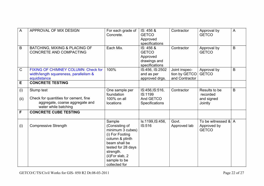
A APPROVAL OF MIX DESIGN For each grade of Concrete.
IS: 456 & GETCOApproved specifications
Contractor Approval by GETCO
A
B BATCHING, MIXING & PLACING OF CONCRETE AND COMPACTING
Each Mix. IS: 456 & GETCOApproved drawings and specifications
Contractor Approval by GETCO
B
C FIXING OF CHIMNEY COLUMN: Check for width/length squareness, parallelism & equidistance
100% IS:456, IS:2502and as perapproved drgs.
Joint inspec-tion by GETCOand Contractor
Approval by GETCO
B
E CONCRETE TESTING
(i)
(ii)
Slump test
Check for quantities for cement, fine aggregate, coarse aggregate and water while batching
One sample per foundation100% on all locations
IS:456,IS:516,IS:1199And GETCO Specifications
Contractor Results to be recordedand signedJointly
B
F CONCRETE CUBE TESTING
(i) Compressive StrengthSample (Consisting of minimum 3 cubes)(i) For Footing column & plinth beam shall be tested for 28 days strength. (ii)For slab, 2 sample to be collected for
Is:1199,IS:456,IS:516
Govt. Approved lab
To be witnessed & Approved byGETCO
A
GETCO/C/TS/Civil Works for GIS- 050 R2 Dt.08-03-2011 Page 22 of 27

7days & 28 days strength test.
G CHECK FINISHING, DIMENSIONAL CONFORMITY AND WORKMANSHIP BEFORE & AFTER BOX REMOVAL
100% IS:456, IS:516,IS:1199
Contractor Approval by GETCO
4 BACKFILLING(i)
(ii)
(iii)
Check for thickness of Layer & watering
Visual check for correction/ramming
Compaction test (Percentage of Max dry density)
100% GETCO Specifications.
Govt. Approved lab
To be witnessed & Approved by GETCO
C
5 BRICK-WORK(i)
(ii)
(iii)
Mortar mix/proportion
Plumb & Alignment
Joints
Random
Random
Random
IS:2250,GETCO Specification
Contractor. Approval by GETCOC
6 PLASTERING
(i)
(ii)
Plastering thickness and evenness
Mortar mix proportion
Random
Random
GETCO Specification
GETCO Specification
Contractor. Approved by GETCO
7 CURING FOR CONCRETE,MASONRY,PLASTERINGETC.
100% on all locations
IS 5613 & GETCO Specification,
Contractor. Approval by GETCO
C
8 SITE SURFACING
GETCO/C/TS/Civil Works for GIS- 050 R2 Dt.08-03-2011 Page 23 of 27

(i)
(ii)(a)
(iii)
(iv)
Levelling
Soil SterilizationSpraying of chemicals
Grading of 20/40/60 mm Stone
Compacted thickness of 20/40/60 mm stone layers as applicable
100%
100%
One sample
Random
GETCO SpecificationGETCO Specification
IS383 & 2386 GETCOSpecs.GETCO Specification
Contractor Approval by GETCO
B
GETCO/C/TS/Civil Works for GIS- 050 R2 Dt.08-03-2011 Page 24 of 27

:GENERAL GUIDELINES FOR IMPLEMENTATION:
1. Details of categories of check codes A,B & C including accepting and deviation disposing authorities are indicated at Annexure-I.
2. GETCO specification shall mean GETCO technical specification, approved drawings, data sheets and law provisions applicable for the specific contract.
3. Acceptance criteria and permissible limits shall be as per relevant Indian Standards and / or prevalent code of practice / GETCO specifications.
4. It is clarified that the tests indicated at column 2 of this FQP i.e. Against column “component operation & Description of test “, are only generally required to be conducted. However GETCO reserves the right to carry-out any additional tests at any stage if the situation so warrants.
5. SE (TR) of circle shall approve testing laboratory before accepting the test results from the lab.
6. SE (TR) of circle shall approve the sources for cement, coarse aggregate, fine aggregate & water before actual utilization.
7. All the testing & measuring equipments used by the contractor for testing are required to be calibrated. A copy of valid calibration report shall be retained by GETCO based on the joint inspection.
8. Classification of foundations shall be approved by GETCO based on the joint inspection report & Soil investigation reports.
9. Zone-IV fine aggregate shall be used for nominal mix Reinforced cement concreting work.
9.1Zone-IV fine aggregate shall be avoided for design mix reinforced cement concreting work unless tests have been done to ascertain the suitability of proposed with the prior approval GETCO sit.
10. CC Blocks/Bricks should be free from cracks, flaws and modules of free lime. They should have smooth rectangular faces with sharp corners and should be uniform in colour.
11. Cement:
11.1 In case of cement is in the scope of the contractor, the same shall be procured from sources approved by GETCO site and got tested on sample basis for specified acceptance tests as specified in the FQP at a reputed third party lab approved by GETCO site.
11.2 The samples of cement for site testing shall be taken within three week of the delivery and all the tests shall be commenced within one week of sampling. If the cement remains in store for a period of more than Six months, all the site tests are required to repeat before usage.
11.3 The source and grade of cement shall be as per approved design mix.
GETCO/C/TS/Civil Works for GIS- 050 R2 Dt.08-03-2011 Page 25 of 27

12. Reinforcement steel & structural steel used in cable trenches & foundations:
12.1 In case supply of steel is in the scope of the contractor, the same shall be procured from the main producers i.e. SAIL, TISCO, IISCO or Rashtriya Ispat Nigam or the rerollers approved by main producers.
12.2 The results of testing of cement and reinforcement steel referred in 11.1 and 12.1 above shall be got approved from GETCO site before cement and reinforcement steel are put to use. However, in exceptional cases due to exigencies of work, GETCO site may authorize the contractor to use cement and reinforcement steel even before the test results are received. However, in all such cases, if the test results subsequently received are found to be not complying with the specified acceptance criteria, the contractor shall have to dismantle and recast all such foundations cast with such non-conforming materials at his own cost. Confirmation to this effect shall be obtained from the contractor by the project authorities beforehand in all such cases.
13. The contractor shall submit welding procedure specification (WPS) including the type of electrode used for approval of GETCO site before staring the welding work. The welder with proper certificate shall be deployed.
14. Approval / acceptance of individual test results by GETCO in the course of execution of contract will neither relieve the contractor from his contractual obligations and responsibilities, nor does it limit the owner’s right under the contract.
15. In case, requirement of special items like super sulphated cement, corrosive resistant reinforcement steel (CRS) etc. arise due to site conditions, the specific approval of GETCO may be obtained before using the same and all the tests as per relevant standards shall be carried out.
16. All the materials shall be stored by the contractor in a manner affording convenient access for identification and inspection at all the times. Storage of material shall be in accordance with IS: 4032 (latest edition).
GETCO/C/TS/Civil Works for GIS- 050 R2 Dt.08-03-2011 Page 26 of 27

ANNEXURE-I
GUJARAT ENERGY TRANSMISSION CORPORATION LIMITED
Accepting and deviation disposing authorities for differentCategories of checks as envisaged in field quality plan
Category
Typeof
Check100% Checking/witnessing by
Countercheck/
Surveillancecheck by
Acceptingauthority, iftest resultsare within
permissiblelimit
Deviationdisposingauthority
A Critical
Executing dept.Plus EE (civil) of circle With Contractor’s Engineer
SE (TR)Plus EE(C)
SE (TR)Plus EE(C)
CE, Corporate
Office
B Major Executing deptt.plus DE(C) EE(C) EE(C) SE(TR)
Plus EE(C)
C Minor Executing deptt.plus JE(C) DE(C) DE(C) EE(C)
Plus DE(C)
GETCO/C/TS/Civil Works for GIS- 050 R2 Dt.08-03-2011 Page 27 of 27