Audi Saradar - STC and Mobily - Company Update - Oct 2012.pdf
GETCO/E/06TS- HYBRID SG 051/R2 Jun ‘12
GUJARAT ENERGY TRANSMISSION
CORPORATION LTD.
SARADAR PATEL VIDYUT BHAVAN, RACE COURSE, BARODA – 390 007.
TECHNICAL SPECIFICATION
FOR
220, 132 & 66 kV HYBRID SWITCHGEAR
GETCO/E/06TS- HYBRID SG 051/R2 Jun ‘12
GETCO/E/06TS- HYBRID SG 051/R2 Jun ‘12
Page 2 of 25
SPECIAL INSTRUCTIONS TO BIDDER Please read following instructions carefully before submitting your bid. 1. All the drawings, i.e. elevation, side view, plan, cross sectional view etc., in
AutoCAD format and manuals in PDF format, for offered item shall be submitted. Also the hard copies as per specification shall be submitted.
2. The bidder shall submit Quality Assurance Plan with the technical bid. 3. The bidder shall have to submit all the required type test reports for the
offered item. In absence of this, the evaluation shall be carried out accordingly as non-submission of type test reports.
4. The bidder must fill up all the points of GTP for offered item/s. Instead of
indicating “refer drawing, or as per IS/IEC”, the exact value/s must be filled in.
5. All the points other than GTP, which are asked to confirm in technical
specifications must be submitted separately with the bid. 6. The bidder is required to impart training in view of manufacture, assembly,
erection, operation and maintenance for offered item, at manufacturer’s works, to the person/s identified by GETCO, in the event of an order, free of cost. The cost of logistics will be borne by GETCO.
7. Please note that the evaluation will be carried out on the strength of
content of bid only. No further correspondence will be made. 8. The bidder shall bring out all the technical deviation/s only at the specified
Annexure.

GETCO/E/06TS- HYBRID SG 051/R2 Jun ‘12
Page 3 of 25
TECHNICAL SPECIFICATION FOR
220, 132 & 66 kV HYBRID SWITCHGEAR
1. SCOPE:
In general, the scope covers the design, engineering, manufacture, assembly, inspection and testing before dispatch, supply, transportation, delivery at given destination, unloading and storage at site, erection, testing and commissioning and putting into successful operation of integrated multifunctional “HYBRID” modules having combination of HV switchgears along with clamp connectors and accessories, tools, tackles, support structure, anchoring bolts, SF6 gas for first filling etc. required for full functionality of the combined unit as per general technical parameters given in this specifications. The scope also covers the supply of spares mentioned in the schedule of respective tender. The scope also covers the civil works for foundation required for HYBRID switchgear module. Special condition / General Technical Requirements (GTR) may please be referred to. The scope also covers the training to GETCO personnel as specified in this specification.
2. GENERAL REQUIREMENTS
The design of HYBRID module shall be such that the Gas Insulated combination of switchgear should be suitable to erect with AIS inlets and bus. The overall space requirement for a particular bay shall be marginally reduced without sacrificing any functionality.
The integrated design has to fulfil the following requirements:
2.1 The module comprising of three nos. of single phase CTs, two nos. of
disconnectors with earth switch and one no of three phase Circuit Breaker shall be fully pre-fabricated in a single compact set and fully tested electrically and mechanically at factory.
2.2 The transport of the module shall be without dismantling of major parts such as
breaker, disconnector and current transformers. 2.3 Preferably the module shall be fully transportable inside containers on standard
trailer on normal road conditions. 2.4 The module shall be designed in order to require the minimum civil work
foundation (i.e. unique concrete platform or even few concrete blocks, only).The foundation details with calculations shall be submitted with the offer
2.5 The module shall be designed to require minimum erection time. Replacement
of one phase of the module shall be possible with a minimum down time of the substation. Therefore it is preferable to have single-phase metal enclosed design.
GETCO/E/06TS- HYBRID SG 051/R2 Jun ‘12
Page 4 of 25
2.6 The hybrid switchgear described in this specification is intended for continuous duty at the specified ratings and under all system operating conditions including sudden change of load and voltage within its ratings and at specified ambient conditions 24 hours a day, 365 days a year.
2.7 Each constituents of the module including Current transformers (CTs) shall be
maintenance free and shall occupy less space. Change of ratio (at secondary terminal blocks) shall be available at accessible place.
2.8 According to the substation lay out, the module shall be able to be connected
with standard AIS components on both sides i.e. line or transformer on one side (using ACSR conductor / Aluminum IPS pipe) and bus bars system supported by standard structure (may be conventional post insulator) unless cable-sealing ends are required on other side. Therefore terminations /bushings shall be suitable for SF6-to-air terminations.
2.9 Electrical interlocking between breaker and the disconnectors / earthing
switches shall be always available. Disconnector shall be provided with the earthing switch. It is preferable to have the mechanism such that mechanical and electrical interlock is always available with disconnector and earth switch.
2.10 The module shall be designed such that it requires the minimum steel structures
for support. The support structure shall also be supplied with module. 2.11 The module shall be designed with minimum number of flanges and optimized
number of gas segregations so as to reduce the risk of gas leakages during the lifespan of the modules.
2.12 It shall be suitable for the future expansion of bays. 2.13 The switchgear must provide the maximum degree of safety for operators and
others in the vicinity of the switchgear under all normal operating conditions and fault conditions.
2.14 It must be impossible to touch any live part of the switchgear unwillingly i.e.
without the use of tools or brute force. 2.15 Operator standing in the normal operating position should not be endangered by
any moving external part of the switchgear. Also the live part to ground clearance shall be maintained as per relevant standards for safe operating conditions.
2.16 All necessary interlocks shall be provided to prevent any mal-operation of the
switchgear. 2.17 In spite of all possible measures of safety an arc occurs, the effect of an internal
arcing fault must be limited to the related gas compartment by bushings. Each gas compartment must have its own pressure relief device to provide instant and safe discharge of accidental overpressure. Such discharge must be directed away from the normal operation position of the switchgear so that persons standing there are not endangered. Internal relief devices between adjacent compartments should be avoided to ensure the gas is directed away from the
GETCO/E/06TS- HYBRID SG 051/R2 Jun ‘12
Page 5 of 25
position. All earthing connections must remain operational. The thickness of enclosure must be able to withstand the arc-burn for a time in accordance with IEC requirements.
2.18 The switchgear shall be suitably subdivided into individual arc and gas proof
compartment so as to limit the effects of an internal arc. 2.19 Joints of different metals that could lead to electrolytic corrosion must be
avoided. 2.20 Adequate filters shall be provided in all the gas compartment to absorb the
residual and entering moisture inside the HV enclosure and also absorb the gas decomposition products resulting from the switching arc.
2.21 Necessary sealing shall be provided to ensure the guaranteed leakage rate of
each gas compartment which shall be less than 0.5 % per annum. 2.22 The module must provide the adequate access for checking and maintenance.
However the overall space requirement for the module shall be kept minimum possible.
2.23 Manual operation shall be always possible in case of failure of the auxiliary
supply. Also portholes shall be provided at an easily accessible place to allow visual inspection of the position whether the component is closed or open.
2.24 Each circuit breaker shall be provided with at least two trip coils. CB should be
suitable for remote control operation. Main contact position of all three poles must be indicated by directly activated auxiliary position switches with at least 8 NO + 8 NC contacts wired to terminal block in the local control panel for purchaser’s use. Each CB shall be provided with an operation counter.
2.25 The operating mechanism shall be capable of performing a complete O-0.3s-
CO-3min-CO sequence. On failure of drive motor or breakdown of the auxiliary power supply, tripping of the CB shall still be possible.
2.26 The actual position of each disconnector and each earhing switch shall be
indicated by mechanically coupled auxiliary switches with at least 8 NO+ 8 NC contacts. Mechanical indicators connected directly and permanently to the drive mechanism shaft are required to display the actual switch position.
2.27 Anti-condensation heaters shall be provided in the control cabinets, in the
operating mechanism housings of disconnectors, earthing switches and Circuit Breakers.
2.28 All the components having ground potential shall be electrically interconnected. 2.29 Current Transformer must have secondary terminals outside the HV enclosure
mounted in suitable accessible terminal boxes. All secondary leads of all CTs must be wired to shorting type terminals.
GETCO/E/06TS- HYBRID SG 051/R2 Jun ‘12
Page 6 of 25
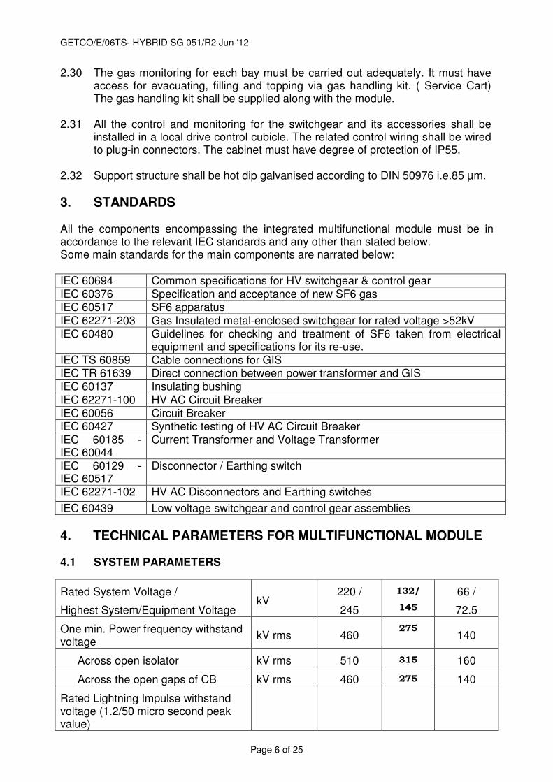
2.30 The gas monitoring for each bay must be carried out adequately. It must have access for evacuating, filling and topping via gas handling kit. ( Service Cart) The gas handling kit shall be supplied along with the module.
2.31 All the control and monitoring for the switchgear and its accessories shall be
installed in a local drive control cubicle. The related control wiring shall be wired to plug-in connectors. The cabinet must have degree of protection of IP55.
2.32 Support structure shall be hot dip galvanised according to DIN 50976 i.e.85 µm.
3. STANDARDS All the components encompassing the integrated multifunctional module must be in accordance to the relevant IEC standards and any other than stated below. Some main standards for the main components are narrated below: IEC 60694 Common specifications for HV switchgear & control gear IEC 60376 Specification and acceptance of new SF6 gas IEC 60517 SF6 apparatus IEC 62271-203 Gas Insulated metal-enclosed switchgear for rated voltage >52kV IEC 60480 Guidelines for checking and treatment of SF6 taken from electrical
equipment and specifications for its re-use. IEC TS 60859 Cable connections for GIS IEC TR 61639 Direct connection between power transformer and GIS IEC 60137 Insulating bushing IEC 62271-100 HV AC Circuit Breaker IEC 60056 Circuit Breaker IEC 60427 Synthetic testing of HV AC Circuit Breaker IEC 60185 - IEC 60044
Current Transformer and Voltage Transformer
IEC 60129 - IEC 60517
Disconnector / Earthing switch
IEC 62271-102 HV AC Disconnectors and Earthing switches
IEC 60439 Low voltage switchgear and control gear assemblies
4. TECHNICAL PARAMETERS FOR MULTIFUNCTIONAL MODULE 4.1 SYSTEM PARAMETERS
Rated System Voltage /
Highest System/Equipment Voltage kV
220 /
245
132/
145
66 /
72.5
One min. Power frequency withstand voltage
kV rms 460 275
140
Across open isolator kV rms 510 315 160
Across the open gaps of CB kV rms 460 275 140
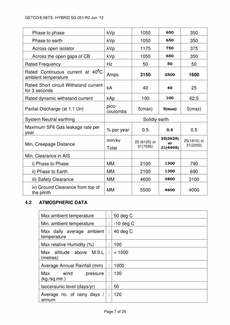
Rated Lightning Impulse withstand voltage (1.2/50 micro second peak value)
GETCO/E/06TS- HYBRID SG 051/R2 Jun ‘12
Page 7 of 25
Phase to phase kVp 1050 650 350
Phase to earth kVp 1050 650 350
Across open isolator kVp 1175 750 375
Across the open gaps of CB kVp 1050 650 350
Rated Frequency Hz 50 50 50
Rated Continuous current at 400C ambient temperature
Amps 3150 2500 1600
Rated Short circuit Withstand current for 3 seconds
kA 40 40 25
Rated dynamic withstand current kAp 100 100 62.5
Partial Discharge (at 1.1 Un) pico-coulombs
5(max) 5(max) 5(max)
System Neutral earthing Solidly earth
Maximum SF6 Gas leakage rate per year
% per year 0.5 0.5 0.5
Min. Creepage Distance mm/kv
Total
25 (6125) or 31(7595)
25(3625) or
31(4495)
25(1815) or 31(2250)
Min. Clearance in AIS
i) Phase to Phase MM 2100 1300 790
ii) Phase to Earth MM 2100 1300 690
iii) Safety Clearance MM 4600 3800 3100
iv) Ground Clearance from top of the plinth
MM 5500 4600 4000
4.2 ATMOSPHERIC DATA
Max ambient temperature : 50 deg C
Min. ambient temperature : -10 deg C
Max daily average ambient temperature
: 40 deg C
Max relative Humidity (%) : 100
Max altitude above M.S.L (metres)
: < 1000
Average Annual Rainfall (mm) : 1000
Max wind pressure (kg./sq.mtr.)
: 130
Isoceraunic level (days/yr) : 50
Average no. of rainy days / annum
: 120
GETCO/E/06TS- HYBRID SG 051/R2 Jun ‘12
Page 8 of 25
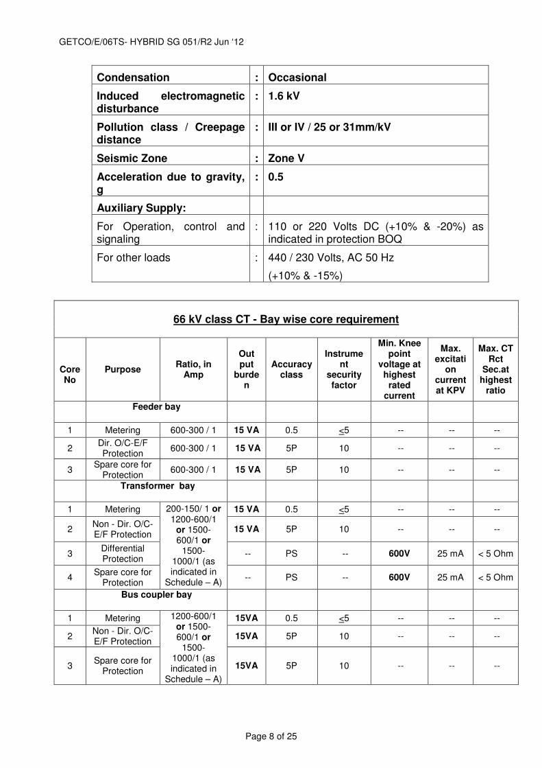
Condensation : Occasional
Induced electromagnetic disturbance
: 1.6 kV
Pollution class / Creepage distance
: III or IV / 25 or 31mm/kV
Seismic Zone : Zone V
Acceleration due to gravity, g
: 0.5
Auxiliary Supply:
For Operation, control and signaling
: 110 or 220 Volts DC (+10% & -20%) as indicated in protection BOQ
For other loads : 440 / 230 Volts, AC 50 Hz
(+10% & -15%)
66 kV class CT - Bay wise core requirement
Core No
Purpose Ratio, in
Amp
Out put
burden
Accuracy class
Instrument
security factor
Min. Knee point
voltage at highest
rated current
Max. excitati
on current at KPV
Max. CT Rct
Sec.at highest
ratio
Feeder bay
1 Metering 600-300 / 1 15 VA 0.5 <5 -- -- --
2 Dir. O/C-E/F Protection
600-300 / 1 15 VA 5P 10 -- -- --
3 Spare core for
Protection 600-300 / 1 15 VA 5P 10 -- -- --
Transformer bay
1 Metering 200-150/ 1 or 1200-600/1
or 1500- 600/1 or
1500- 1000/1 (as indicated in
Schedule – A)
15 VA 0.5 <5 -- -- --
2 Non - Dir. O/C-E/F Protection
15 VA 5P 10 -- -- --
3 Differential Protection
-- PS -- 600V 25 mA < 5 Ohm
4 Spare core for
Protection -- PS -- 600V 25 mA < 5 Ohm
Bus coupler bay
1 Metering 1200-600/1 or 1500- 600/1 or
1500- 1000/1 (as indicated in
Schedule – A)
15VA 0.5 <5 -- -- --
2 Non - Dir. O/C-E/F Protection
15VA 5P 10 -- -- --
3 Spare core for
Protection 15VA 5P 10 -- -- --
GETCO/E/06TS- HYBRID SG 051/R2 Jun ‘12
Page 9 of 25
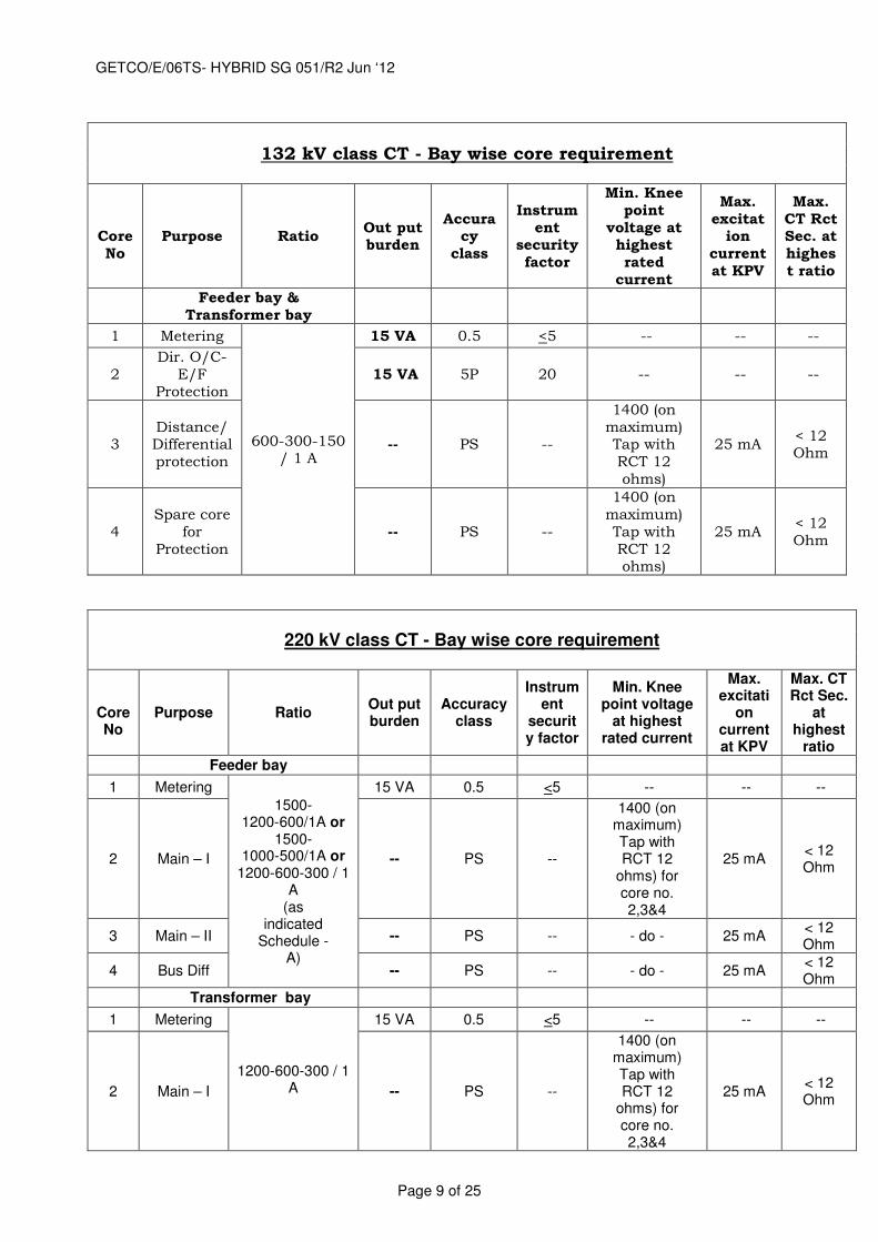
132 kV class CT - Bay wise core requirement
Core No
Purpose Ratio Out put burden
Accuracy
class
Instrument
security factor
Min. Knee point
voltage at highest rated
current
Max. excitat
ion current at KPV
Max. CT Rct Sec. at highest ratio
Feeder bay &
Transformer bay
1 Metering
600-300-150 / 1 A
15 VA 0.5 <5 -- -- --
2 Dir. O/C-
E/F Protection
15 VA 5P 20 -- -- --
3 Distance/Differential protection
-- PS --
1400 (on maximum) Tap with RCT 12 ohms)
25 mA < 12 Ohm
4 Spare core
for Protection
-- PS --
1400 (on maximum) Tap with RCT 12 ohms)
25 mA < 12 Ohm
220 kV class CT - Bay wise core requirement
Core No
Purpose Ratio Out put burden
Accuracy class
Instrument
security factor
Min. Knee point voltage
at highest rated current
Max. excitati
on current at KPV
Max. CT Rct Sec.
at highest
ratio
Feeder bay
1 Metering
1500- 1200-600/1A or
1500- 1000-500/1A or
1200-600-300 / 1 A
(as indicated
Schedule - A)
15 VA 0.5 <5 -- -- --
2 Main – I -- PS --
1400 (on maximum) Tap with RCT 12
ohms) for core no. 2,3&4
25 mA < 12 Ohm
3 Main – II -- PS -- - do - 25 mA < 12 Ohm
4 Bus Diff -- PS -- - do - 25 mA < 12 Ohm
Transformer bay
1 Metering
1200-600-300 / 1 A
15 VA 0.5 <5 -- -- --
2 Main – I -- PS --
1400 (on maximum) Tap with RCT 12
ohms) for core no. 2,3&4
25 mA < 12 Ohm
GETCO/E/06TS- HYBRID SG 051/R2 Jun ‘12
Page 10 of 25
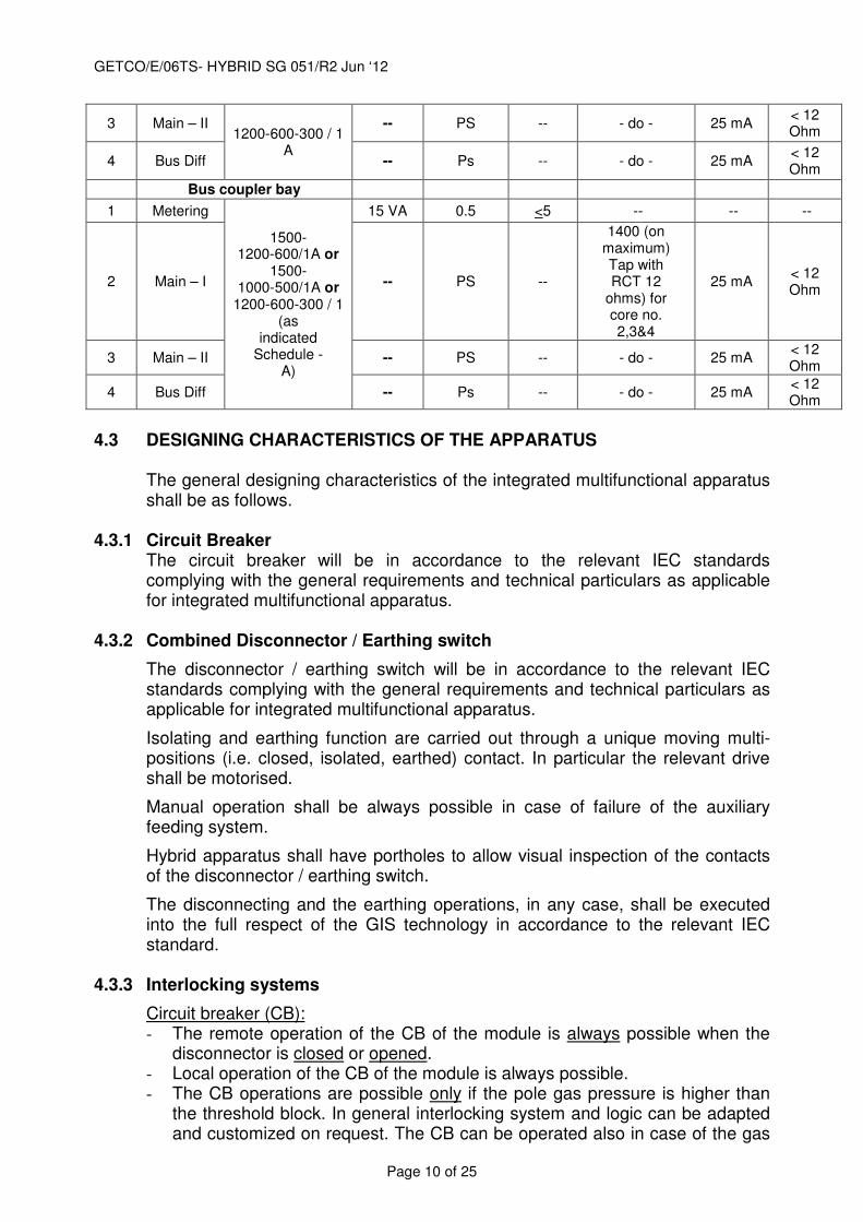
3 Main – II 1200-600-300 / 1
A
-- PS -- - do - 25 mA < 12 Ohm
4 Bus Diff -- Ps -- - do - 25 mA < 12 Ohm
Bus coupler bay
1 Metering
1500- 1200-600/1A or
1500- 1000-500/1A or
1200-600-300 / 1 (as
indicated Schedule -
A)
15 VA 0.5 <5 -- -- --
2 Main – I -- PS --
1400 (on maximum) Tap with RCT 12
ohms) for core no. 2,3&4
25 mA < 12 Ohm
3 Main – II -- PS -- - do - 25 mA < 12 Ohm
4 Bus Diff -- Ps -- - do - 25 mA < 12 Ohm
4.3 DESIGNING CHARACTERISTICS OF THE APPARATUS
The general designing characteristics of the integrated multifunctional apparatus shall be as follows.
4.3.1 Circuit Breaker The circuit breaker will be in accordance to the relevant IEC standards complying with the general requirements and technical particulars as applicable for integrated multifunctional apparatus.
4.3.2 Combined Disconnector / Earthing switch
The disconnector / earthing switch will be in accordance to the relevant IEC standards complying with the general requirements and technical particulars as applicable for integrated multifunctional apparatus.
Isolating and earthing function are carried out through a unique moving multi-positions (i.e. closed, isolated, earthed) contact. In particular the relevant drive shall be motorised.
Manual operation shall be always possible in case of failure of the auxiliary feeding system.
Hybrid apparatus shall have portholes to allow visual inspection of the contacts of the disconnector / earthing switch.
The disconnecting and the earthing operations, in any case, shall be executed into the full respect of the GIS technology in accordance to the relevant IEC standard.
4.3.3 Interlocking systems
Circuit breaker (CB): - The remote operation of the CB of the module is always possible when the
disconnector is closed or opened. - Local operation of the CB of the module is always possible. - The CB operations are possible only if the pole gas pressure is higher than
the threshold block. In general interlocking system and logic can be adapted and customized on request. The CB can be operated also in case of the gas
GETCO/E/06TS- HYBRID SG 051/R2 Jun ‘12
Page 11 of 25
pressure drop down to the atmospheric value. In this case, the power frequency withstand voltage (1 min) must be guaranteed.
Disconnector/Earthing switch - The disconnector/earthing switch operation (both motor and manually
operated) is possible only when the CB is opened (the interlocking device shall be electromagnetic). It is understood that all the manufacturers have their own design for the DS and the ES. By the way a design combining together DS/ES is preferred because of the natural mechanical interlocking between the two functions.
All the interlocking shall be in accordance to the relevant IEC standard in order to allow the operations in fully safety conditions for the operators. 4.3.4 Current Transformers
- Typical Burdens and Performances The current transformers will be in accordance to the relevant IEC standard. The parameters required are as given in this specification.
4.4 ELECTRIC INTERFACING WITH THE CONTROL AND PROTECTION
SYSTEM FOR HYBRID SYSTEM.
The module shall be supplied with a unique local control cabinet, fully pre-fabricated, pre-wired and pre-tested as unique interface between the multifunctional module and the control and protection system of the whole substation. In order to minimize wiring and cabling at the site and consequently the risk of wrong electrical connections, modules shall have the plug-in connectors from the local control cabinet to the drive mechanisms of the circuit breaker and to the drive mechanism of the disconector and earthing switch. The module shall be SCADA compatible. (Please refer tech spec and philosophy for protection.)
4.5 Bushings
All the bushings for the module shall be polymer type complying with general technical parameters and relevant IEC standards.
4.6 STEEL STRUCTURE
The steel structure will be made of hot dip galvanised steel.
5. Type Tests:
Following type test reports from NABL laboratory, as specified in IEC standards (amended up to date) shall be submitted for the offered type, rating of module invariably with the technical bid. Bid without type test reports will not be considered for evaluation. The type test reports shall not be older than five years and shall be valid up to expiry of validity of offer.
Important note for type tests: The type test report shall be submitted for the offered class and rating of the module. However, the type test report for higher class/rating can be accepted for scrutiny of technical bid but the same test/s shall have to be carried out on the offered class/rating. Bidder shall invariably
GETCO/E/06TS- HYBRID SG 051/R2 Jun ‘12
Page 12 of 25
confirm to carry out the required type test/s, special tests, before commencement of supply, without affecting delivery schedule, free of cost, at NABL approved laboratory, or at suppliers works in presence of GETCO representative, in the event of order.
In absence of this confirmation, the offer will be evaluated as non submission of type test report.
1. Tests to verify the insulation level (Lightning impulse, Switching impulse
and ac withstand test with PD) test on each device (CB, Disconnector, etc).
2. Dielectric tests on auxiliary circuits. 3. Tests to prove the radio interference voltage (RIV) level. 4. Tests to prove the temperature rise of any part of the equipment and
measurement of the resistance of the main circuit. 5. Tests to prove the ability of the main and earthing circuits to carry the
rated peak and the rated short time withstand current. 6. Tests to verify the making and breaking capacity of the included switching
devices. 7. Tests to prove the satisfactory operation of the included switching
devices. 8. Tests to prove the strength of enclosures. 9. Verification of the degree of protection of the enclosure. 10. Gas tightness tests 11. Additional tests on auxiliary and control circuits. 12. Tests on partitions. 13. Tests to prove the satisfactory operation at limit temperatures. 14. Tests to prove performance under thermal cycling and gas tightness tests
on insulators. 15. Corrosion test on earthing connections (if applicable). 16. Tests to assess the effects of arcing due to an internal fault. 17. Tests on solid dielectric components (operating rods, spacers, etc) 18. Seismic test 19. Test on Auxiliary switches (Electrical & Mechanical Endurance, Heat run,
IR & HV test)
6. Routine / Acceptance Testing:
During manufacture and on completion, all equipment shall be subjected to the Routine tests as laid down in IEC Standards. All the acceptance tests shall be carried out in presence of GETCO representative on offering the material for inspection and testing by successful bidder. Tests shall include the following:
1. Dielectric test on the main circuit. 2. PD test 3. Tests on auxiliary and control circuits. 4. Measurement of the resistance of the main circuit. 5. Tightness test. 6. Design and visual checks. 7. Pressure tests of enclosures. 8. Functional tests
GETCO/E/06TS- HYBRID SG 051/R2 Jun ‘12
Page 13 of 25
9. Tests on auxiliary circuits, equipment and interlocks in the control mechanism.
10. Pressure test on partitions. 7. Test Certificates:
a. Certified reports of all the tests carried out at the works shall be furnished in required number copies for approval of the Owner.
b. The equipment shall be dispatched from works only after receipt of Owner/ Purchaser's written dispatch clearance & approval of the test reports.
c. Routine test certificates of bought out components shall be furnished. d. Type test certificate on any equipment or component if so desired by the
Owner shall be furnished. Otherwise the equipment shall have to be type tested, free of charge, to prove the design.
8. Tests after installation of complete module at Site:
After installation and before being put into service, the module shall be tested in order to check the correct operation and dielectric integrity of the equipment as laid down in IEC. The successful bidder shall furnish a commissioning test plan and a statement method for the tests on site. Tests shall include the following:
1. Dielectric tests on the main circuits. 2. Dielectric tests on auxiliary circuits. 3. Measurement of the resistance of the main circuit. 4. Gas tightness tests. 5. Checks and verifications. 6. Gas quality verifications. 7. On site power frequency voltage withstand test with PD test. 8. All applicable Tests as per IEEE C37.122.1 clause 4.10.5 9. Functional & interlock tests for all items 10. Demonstration of operational compatibility with SCADA 11. Visual inspection, checks & verifications.
12. Mechanical operation tests of circuit breakers, Disconnectors and earthing switches and high-speed earthing switches
13. Insulation resistance measurement 14. Tests on CTs
8.1 Required test equipment
During the on site tests, the supplier shall provide all necessary test facilities and equipment for the switch-gear power frequency tests, i.e. test bushing or test cable, test adapter, test transformer or resonant test set etc.
9. SPARES:
Bidder shall supply following spares free of cost.
i) SF6 gas leak detector -1 set
GETCO/E/06TS- HYBRID SG 051/R2 Jun ‘12
Page 14 of 25
ii) Electolytic hygrometer complete with piping( due point measurement kit) -1 Set
iii) Portable Gas filling and evacuating plant ( service Cart) suitable for module with required hose, adapters, stand, etc and all accessories. -1 set.
iv) 10% extra gas for each module. v) Special tools, tackles & spanner required during commissioning,
operation and maintenance. vi) Viewing mechanism (if required) so as to view the posion from
accessible point on ground.
10. DRAWINGS, DATA & MANUALS:
Drawings, Data and Manuals shall be submitted in triplicate with the bid and in quantities and procedures as specified in General Conditions on Contract and/or elsewhere in this specification for approval and subsequent distribution after the issue of Letter of Intent.
To be submitted with the Bid:
1. Typical general arrangement drawings of the equipments indicating space
requirement, etc. 2. Technical Specifications of equipment and special tools explaining construction
features, principle of operation, special features etc. 3. Comprehensive QAP, FQP, SLD, colour Gas Schematic diagram, Technical
brochures, foundation requirements, List of recommended spares, special tools or fixtures, O&M manuals, environmental guide for handling SF6 gas & decommissioning, estimated time schedule for installation & commissioning, bill of materials, and any other documents required for successful commissioning & operation of complete module..
4. Control and protection:(If included in scope of supply in Schedule – A of respective tender)
Block & principle diagram showing proposed scheme, layout & equipment arrangement drawings, catalogues & brochures of offered devices.
Successful bidder shall submit 3 sets of spiral bound volume of following drawings & data for approval before commencement of supply:
1. A comprehensive Manufacturing Quality assurance plan with effective quality
assurance system. 2. Field Quality plan indicating instruction & procedures sequenced for storage,
assemble, maintenance and disassembly. 3. Assemble and maintenance clearance requirements. 4. Dimensional general arrangement drawing showing disposition of various
fittings, name plates indicating equipment ratings. 5. Structure Plan with details and loading 6. Foundation plan indicating loadings for all hybrid equipment, complete module,
supporting structure and anchor bolt arrangements. 7. Assembly drawing for erection at site with part numbers and schedule of
materials Transport/shipping dimensions with weights. 8. Control schematic and wiring diagrams. 9. Gas schematic Diagram
GETCO/E/06TS- HYBRID SG 051/R2 Jun ‘12
Page 15 of 25
10. Gas system installation procedures, gas handling procedures. 11. Grounding arrangement and ground bus details including Manufacturer’s
recommendation on Grounding of reinforcement bars of Column foundation. 12. Calculation of Voltage rise for hybrid enclosure 13. Calculated point to point resistance for each assembly. 14. Calculation for Surge Protection 15. Any other relevant drawing or data necessary for satisfactory installation,
operation and maintenance. 16. Operating instruction & manuals for module and its accessories 17. The manual shall clearly indicate method of installation, check ups and tests to
be carried out before commissioning of the equipment. 18. The bidder shall note that the approval of drawings & documents by the Owner
does not relieve him of his contractual obligation.
The bidder may note that the drawings, data and manuals listed herein are minimum required only. The bidder shall ensure that all other necessary write-up, curves, etc require to fully describe the equipment are to be submitted with the bid.
All drawings shall be prepared by using AutoCAD and documents shall be generated using Electronic version. The paper copy of the drawings & document shall be submitted for approval & reference. All final drawings and documents shall be submitted in CD in AutoCAD 2007 and MS office format as applicable for Owner’s future reference. Also AutoCAD version of Main GA drawings is to be submitted for Owner’s layout finalization.
11. MAINTENANCE:
The operational integrity of the switchgear shall not subject to external influences, such as pollution, moisture, dust etc. As a consequence of this switchgear should be practically maintenance free, however, the details of inspection required at regular interval shall be indicated in the offer. Visual inspection shall be required not below 2 (two) years interval. Inspection shall not be required often than every 10 years. During inspection it must not be necessary to open the switchgear enclosures for interrupt operation of substation. Provision of functional testing of the close and trip coils, auxiliary switches, pressure and control switches etc. shall be provided. Following minimum maintenance period shall be accepted.
(a) Circuit breaker: 5000 closing and opening or 20 interruption at max rated current
(b) Disconnector: 5000 closing and opening operations.
(c) Fast acting earth switch: 2000 closing and opening operations or 2 making operations on to max rated fault current.
The bidder shall provide the services of experienced persons, supervisors, engineers, experts, etc., for complete specified work for satisfactory operation.
The bidder shall have dedicated localized after sales & service team which should be capable any activity to operate complete module satisfactorily.
GETCO/E/06TS- HYBRID SG 051/R2 Jun ‘12
Page 16 of 25
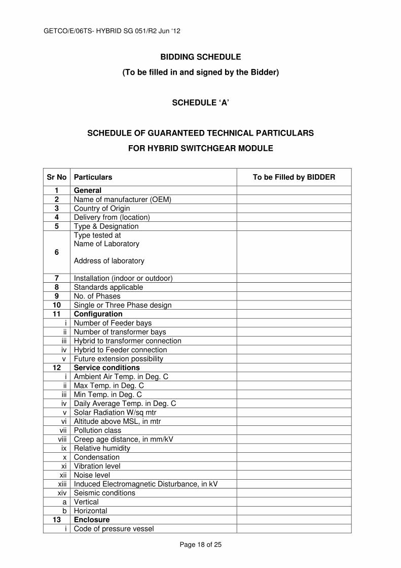
12. Guaranteed and technical particulars as called for in attached SCHEDULE ‘A’ shall be furnished along with the technical bid.
13. Training:
Training to Ten (10) persons of GETCO on construction, installation, commissioning and O&M shall be imparted by bidder free of cost.
Duration of the complete training shall be 7 working days, covering minimum below specified curriculum. Any other specific area may be brought to notice and included. 1. General Explanation for MODULE
2. Layout and Architecture of MODULE
3. Gas Sectionalisation of MODULE
4. Construction of CB
5. Operating Mechanism of CB
6. Maintenance of CB
7. Overhaul of CB (Interrupting chamber)
8. Overhaul of CB (Operating Unit)
9. Construction of Disconnector/ES
10. Maintenance of Disconnector/ES
11. Overhaul of Disconnector/ES
12. Construction of Cable head/ SF6 – air bushing
13. Maintenance of Cable head/ SF6 – air bushing
14. Overhaul of Cable head/connectors
15. Overhaul of various transformer connections
16. Operation of MODULE with SCADA
17. Construction & Maintenance of CT
18. Construction & Maintenance of Local control panel
19. Erection of MODULE at site.
20. Installation & Testing of MODULE at site
22. Type tests of MODULE
23. Routine tests of MODULE.
24. Faults simulation of MODULE
25. Localization of MODULE fault.
Bidder shall at his cost arrange for the above training facilities and in addition shall bear all living expenses plus inland travel expenses of all the trainees. The Purchaser shall only pay to and fro passage of the trainees.
GETCO/E/06TS- HYBRID SG 051/R2 Jun ‘12
Page 17 of 25
14.0. PACKING AND TRANSPORT The Bidders shall indicate during the tendering phases the packing and the transport conditions of the module considering that the module preferably shall be fully transportable inside standard ISO container or wooden boxes suitable for inland or overseas transport without dismantling the major parts (i.e. CB, DS/ES, Bushings, CTs).
15.0 QUALITY ASSURANCE
Superior quality control system shall be adopted to assure high product quality.
Raw materials of the best commercial grade quality and high reliability shall be
used in the manufacture of module. High reliability of materials shall be ensured so
as to keep maintenance work to a minimum.
A quality assurance plan for major components such as breakers, disconnecting
switches, earth switches, etc. with in-process inspection methods, tests, records,
etc. shall be submitted with the technical bid. Customer hold points will also be
included in the plan, which shall be mutually agreed by the PURCHASER and
MANUFACTURER, and approved.
GETCO/E/06TS- HYBRID SG 051/R2 Jun ‘12
Page 18 of 25
BIDDING SCHEDULE
(To be filled in and signed by the Bidder)
SCHEDULE ‘A’
SCHEDULE OF GUARANTEED TECHNICAL PARTICULARS
FOR HYBRID SWITCHGEAR MODULE
Sr No Particulars To be Filled by BIDDER
1 General 2 Name of manufacturer (OEM) 3 Country of Origin 4 Delivery from (location) 5 Type & Designation
6
Type tested at Name of Laboratory Address of laboratory
7 Installation (indoor or outdoor) 8 Standards applicable 9 No. of Phases
10 Single or Three Phase design 11 Configuration
i Number of Feeder bays ii Number of transformer bays iii Hybrid to transformer connection
iv Hybrid to Feeder connection v Future extension possibility
12 Service conditions i Ambient Air Temp. in Deg. C ii Max Temp. in Deg. C
iii Min Temp. in Deg. C iv Daily Average Temp. in Deg. C
v Solar Radiation W/sq mtr vi Altitude above MSL, in mtr
vii Pollution class viii Creep age distance, in mm/kV ix Relative humidity
x Condensation xi Vibration level
xii Noise level xiii Induced Electromagnetic Disturbance, in kV xiv Seismic conditions
a Vertical b Horizontal
13 Enclosure i Code of pressure vessel
GETCO/E/06TS- HYBRID SG 051/R2 Jun ‘12
Page 19 of 25
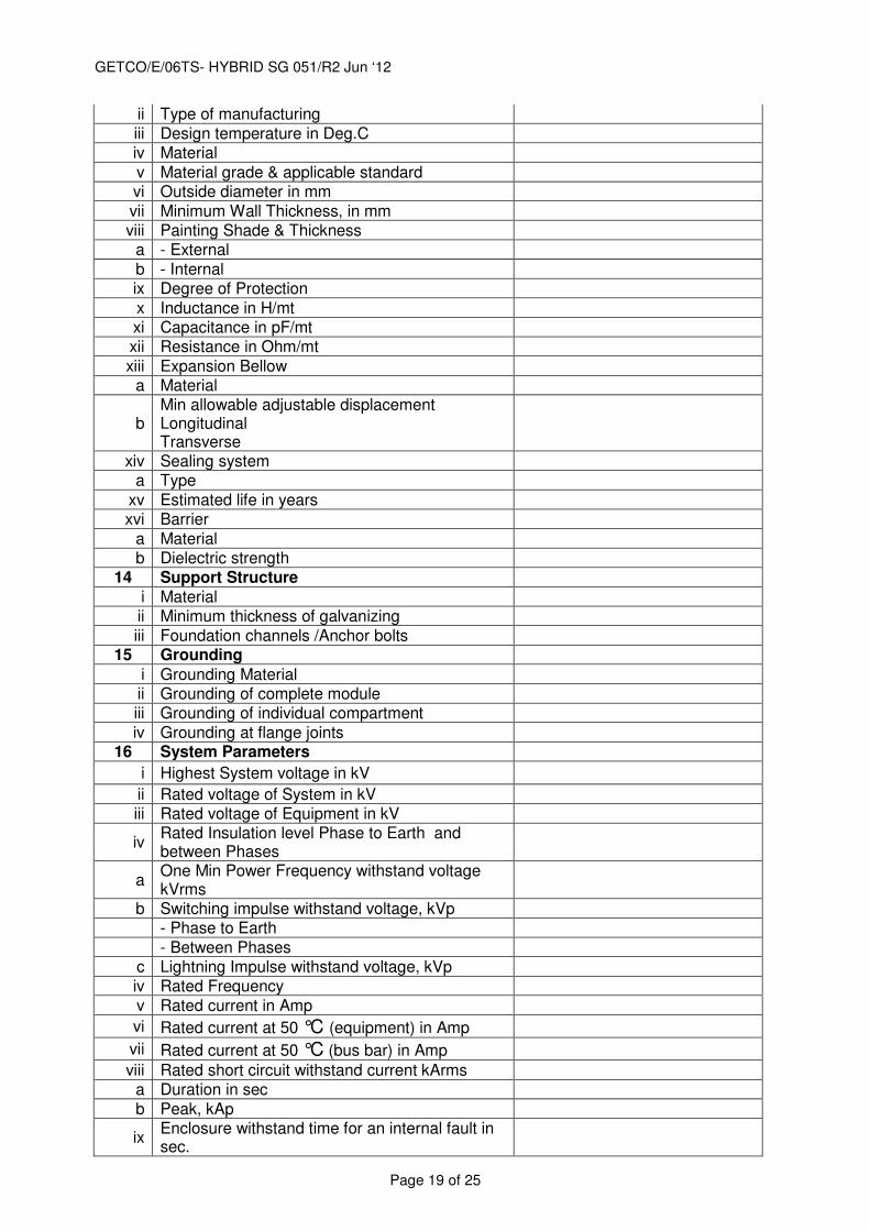
ii Type of manufacturing
iii Design temperature in Deg.C iv Material
v Material grade & applicable standard vi Outside diameter in mm
vii Minimum Wall Thickness, in mm viii Painting Shade & Thickness
a - External
b - Internal ix Degree of Protection
x Inductance in H/mt xi Capacitance in pF/mt xii Resistance in Ohm/mt
xiii Expansion Bellow a Material
b Min allowable adjustable displacement Longitudinal Transverse
xiv Sealing system a Type
xv Estimated life in years xvi Barrier
a Material b Dielectric strength
14 Support Structure i Material ii Minimum thickness of galvanizing
iii Foundation channels /Anchor bolts 15 Grounding
i Grounding Material ii Grounding of complete module iii Grounding of individual compartment
iv Grounding at flange joints 16 System Parameters
i Highest System voltage in kV
ii Rated voltage of System in kV iii Rated voltage of Equipment in kV
iv Rated Insulation level Phase to Earth and between Phases
a One Min Power Frequency withstand voltage kVrms
b Switching impulse withstand voltage, kVp - Phase to Earth
- Between Phases c Lightning Impulse withstand voltage, kVp iv Rated Frequency
v Rated current in Amp
vi Rated current at 50 °C (equipment) in Amp
vii Rated current at 50 °C (bus bar) in Amp
viii Rated short circuit withstand current kArms a Duration in sec
b Peak, kAp
ix Enclosure withstand time for an internal fault in sec.
GETCO/E/06TS- HYBRID SG 051/R2 Jun ‘12
Page 20 of 25
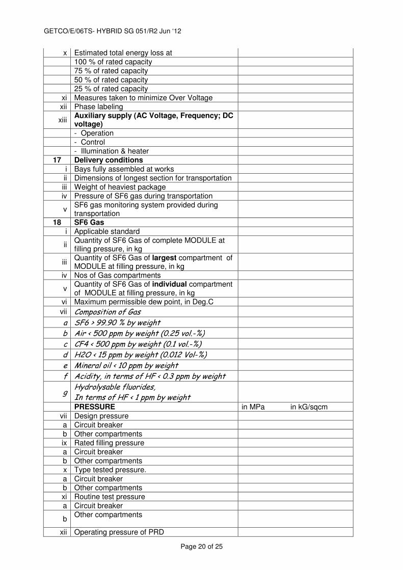
x Estimated total energy loss at
100 % of rated capacity 75 % of rated capacity
50 % of rated capacity 25 % of rated capacity
xi Measures taken to minimize Over Voltage xii Phase labeling
xiii Auxiliary supply (AC Voltage, Frequency; DC voltage)
- Operation
- Control - Illumination & heater
17 Delivery conditions i Bays fully assembled at works ii Dimensions of longest section for transportation
iii Weight of heaviest package iv Pressure of SF6 gas during transportation
v SF6 gas monitoring system provided during transportation
18 SF6 Gas i Applicable standard
ii Quantity of SF6 Gas of complete MODULE at filling pressure, in kg
iii Quantity of SF6 Gas of largest compartment of MODULE at filling pressure, in kg
iv Nos of Gas compartments
v Quantity of SF6 Gas of individual compartment of MODULE at filling pressure, in kg
vi Maximum permissible dew point, in Deg.C
vii Composition of Gas
a SF6 > 99.90 % by weight
b Air < 500 ppm by weight (0.25 vol.-%)
c CF4 < 500 ppm by weight (0.1 vol.-%)
d H2O < 15 ppm by weight (0.012 Vol-%)
e Mineral oil < 10 ppm by weight
f Acidity, in terms of HF < 0.3 ppm by weight
g Hydrolysable fluorides, In terms of HF < 1 ppm by weight
PRESSURE in MPa in kG/sqcm
vii Design pressure a Circuit breaker
b Other compartments ix Rated filling pressure a Circuit breaker
b Other compartments x Type tested pressure.
a Circuit breaker b Other compartments xi Routine test pressure
a Circuit breaker
b Other compartments
xii Operating pressure of PRD
GETCO/E/06TS- HYBRID SG 051/R2 Jun ‘12
Page 21 of 25
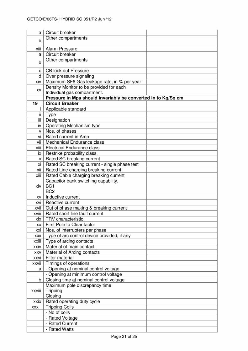
a Circuit breaker
b Other compartments
xiii Alarm Pressure a Circuit breaker
b Other compartments
c CB lock out Pressure d Over pressure signaling
xiv Maximum SF6 Gas leakage rate, in % per year
xv Density Monitor to be provided for each Individual gas compartment.
Pressure in Mpa should invariably be converted in to Kg/Sq cm 19 Circuit Breaker
i Applicable standard ii Type
iii Designation
iv Operating Mechanism type v Nos. of phases
vi Rated current in Amp vii Mechanical Endurance class
viii Electrical Endurance class ix Restrike probability class x Rated SC breaking current
xi Rated SC breaking current - single phase test xii Rated Line charging breaking current
xiii Rated Cable charging breaking current
xiv Capacitor bank switching capability, BC1 BC2
xv Inductive current xvi Reactive current xvii Out of phase making & breaking current
xviii Rated short line fault current xix TRV characteristic
xx First Pole to Clear factor xxi Nos. of interrupters per phase xxii Type of arc control device provided, if any
xxiii Type of arcing contacts xxiv Material of main contact
xxv Material of Arcing contacts xxvi Filter material
xxvii Timings of operations a - Opening at nominal control voltage - Opening at minimum control voltage
b Closing time at nominal control voltage
xxviii Maximum pole discrepancy time Tripping Closing
xxix Rated operating duty cycle xxx Tripping Coils
- No of coils
- Rated Voltage - Rated Current
- Rated Watts
GETCO/E/06TS- HYBRID SG 051/R2 Jun ‘12
Page 22 of 25
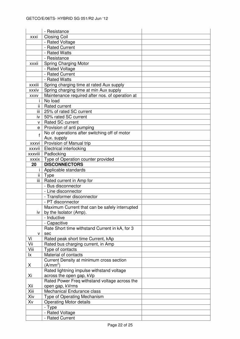
- Resistance
xxxi Closing Coil - Rated Voltage
- Rated Current - Rated Watts
- Resistance xxxii Spring Charging Motor
- Rated Voltage
- Rated Current - Rated Watts
xxxiii Spring charging time at rated Aux supply xxxiv Spring charging time at min Aux supply xxxv Maintenance required after nos. of operation at
i No load ii Rated current
iii 25% of rated SC current iv 50% rated SC current
v Rated SC current e Provision of anti pumping
f No of operations after switching off of motor Aux. supply
xxxvi Provision of Manual trip xxxvii Electrical interlocking xxxviii Padlocking
xxxix Type of Operation counter provided 20 DISCONNECTORS
i Applicable standards ii Type
iii Rated current in Amp for
- Bus disconnector
- Line disconnector
- Transformer disconnector - PT disconnector
iv Maximum Current that can be safely interrupted by the Isolator (Amp).
- Inductive
- Capacitive
v Rate Short time withstand Current in kA, for 3 sec
Vi Rated peak short time Current, kAp
Vii Rated bus charging current, in Amp
Viii Type of contacts
Ix Material of contacts
X Current Density at minimum cross section (A/mm2)
Xi Rated lightning impulse withstand voltage across the open gap, kVp
Xii Rated Power Freq withstand voltage across the open gap, kVrms
Xiii Mechanical Endurance class
Xiv Type of Operating Mechanism
Xv Operating Motor details
- Type
- Rated Voltage - Rated Current
GETCO/E/06TS- HYBRID SG 051/R2 Jun ‘12
Page 23 of 25
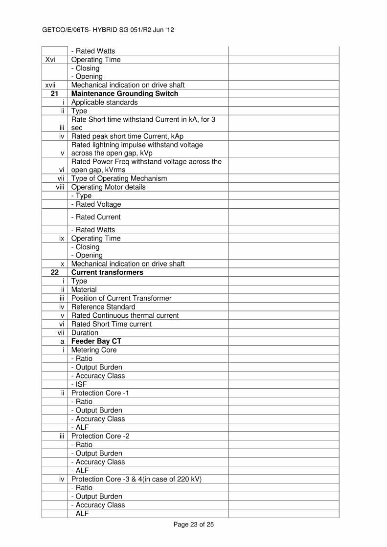
- Rated Watts Xvi Operating Time
- Closing - Opening
xvii Mechanical indication on drive shaft 21 Maintenance Grounding Switch
i Applicable standards
ii Type
iii Rate Short time withstand Current in kA, for 3 sec
iv Rated peak short time Current, kAp
v Rated lightning impulse withstand voltage across the open gap, kVp
vi Rated Power Freq withstand voltage across the open gap, kVrms
vii Type of Operating Mechanism
viii Operating Motor details - Type
- Rated Voltage
- Rated Current
- Rated Watts ix Operating Time
- Closing - Opening
x Mechanical indication on drive shaft 22 Current transformers
i Type
ii Material iii Position of Current Transformer
iv Reference Standard v Rated Continuous thermal current vi Rated Short Time current
vii Duration a Feeder Bay CT
i Metering Core - Ratio
- Output Burden - Accuracy Class - ISF
ii Protection Core -1 - Ratio
- Output Burden - Accuracy Class - ALF
iii Protection Core -2 - Ratio
- Output Burden - Accuracy Class
- ALF iv Protection Core -3 & 4(in case of 220 kV)
- Ratio
- Output Burden - Accuracy Class
- ALF
GETCO/E/06TS- HYBRID SG 051/R2 Jun ‘12
Page 24 of 25
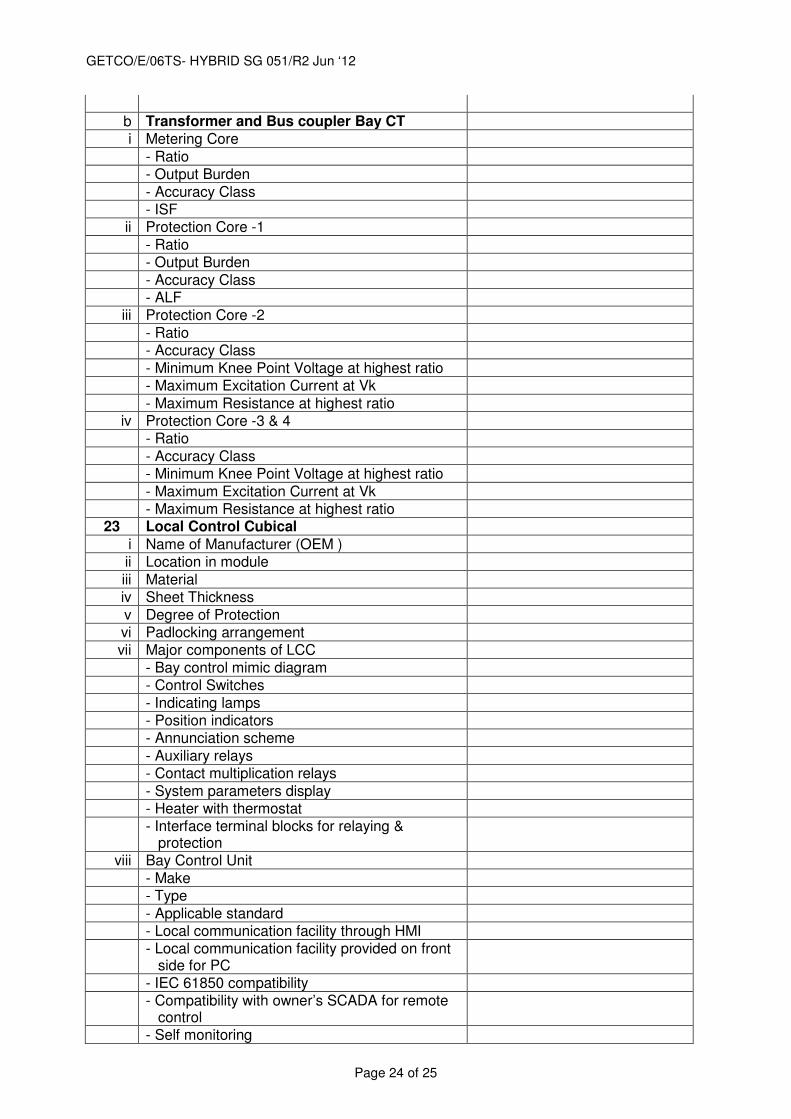
b Transformer and Bus coupler Bay CT i Metering Core
- Ratio - Output Burden
- Accuracy Class - ISF
ii Protection Core -1
- Ratio - Output Burden
- Accuracy Class - ALF
iii Protection Core -2
- Ratio - Accuracy Class
- Minimum Knee Point Voltage at highest ratio - Maximum Excitation Current at Vk
- Maximum Resistance at highest ratio iv Protection Core -3 & 4
- Ratio
- Accuracy Class - Minimum Knee Point Voltage at highest ratio
- Maximum Excitation Current at Vk - Maximum Resistance at highest ratio
23 Local Control Cubical
i Name of Manufacturer (OEM ) ii Location in module
iii Material iv Sheet Thickness
v Degree of Protection vi Padlocking arrangement vii Major components of LCC
- Bay control mimic diagram - Control Switches
- Indicating lamps - Position indicators - Annunciation scheme
- Auxiliary relays - Contact multiplication relays
- System parameters display - Heater with thermostat
- Interface terminal blocks for relaying &
protection
viii Bay Control Unit
- Make - Type
- Applicable standard - Local communication facility through HMI
- Local communication facility provided on front
side for PC
- IEC 61850 compatibility
- Compatibility with owner’s SCADA for remote
control
- Self monitoring
GETCO/E/06TS- HYBRID SG 051/R2 Jun ‘12
Page 25 of 25
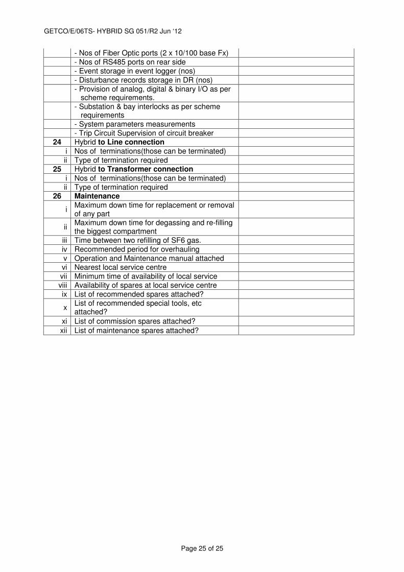
- Nos of Fiber Optic ports (2 x 10/100 base Fx)
- Nos of RS485 ports on rear side
- Event storage in event logger (nos)
- Disturbance records storage in DR (nos)
- Provision of analog, digital & binary I/O as per
scheme requirements.
- Substation & bay interlocks as per scheme
requirements
- System parameters measurements
- Trip Circuit Supervision of circuit breaker
24 Hybrid to Line connection
i Nos of terminations(those can be terminated)
ii Type of termination required
25 Hybrid to Transformer connection
i Nos of terminations(those can be terminated)
ii Type of termination required 26 Maintenance
i Maximum down time for replacement or removal of any part
ii Maximum down time for degassing and re-filling the biggest compartment
iii Time between two refilling of SF6 gas.
iv Recommended period for overhauling
v Operation and Maintenance manual attached
vi Nearest local service centre
vii Minimum time of availability of local service viii Availability of spares at local service centre ix List of recommended spares attached?
x List of recommended special tools, etc attached?
xi List of commission spares attached?
xii List of maintenance spares attached?