
SAP Enterprise Asset Management PM
265
-
Upload
cavalencia -
Category
Documents
-
view
179 -
download
3
Transcript of SAP Enterprise Asset Management PM


ENTERPRISE ASSET MANAGEMENT


ENTERPRISE ASSET MANAGEMENT
CONFIGURING AND ADMINISTERING
SAP R/3 PLANT MAINTENANCE
Ian McMullan
iUniverse, Inc.New York Lincoln Shanghai

Enterprise Asset ManagementConfiguring and Administering SAP R/3 Plant Maintenance
All Rights Reserved © 2004 by Ian McMullan
No part of this book may be reproduced or transmitted in any form or by anymeans, graphic, electronic, or mechanical, including photocopying, recording,
taping, or by any information storage retrieval system, without the writtenpermission of the publisher.
iUniverse, Inc.
For information address:iUniverse, Inc.
2021 Pine Lake Road, Suite 100Lincoln, NE 68512www.iuniverse.com
ISBN: 0-595-77379-6
Printed in the United States of America

The configuration and instructions contained herein have been included fortheir instructional value. Neither the author nor the publisher offer any war-ranties or representations in respect of their fitness for a particular purpose, andneither the author nor the publisher accept any liability for loss or damage aris-ing from their use.
“SAP” and mySAP.com are trademarks of SAPAktiengesellschaft, Systems,Applications and Products in Data Processing, Neurottstrasse16, 69190Walldorf, Germany. The publisher gratefully acknowledges SAP’s kind permis-sion to use its trademark in this publication. SAP AG is not the publisher ofthis book and is not responsible for it under any aspect of press law.
SAP, the SAP logo, mySAP, SAP R/3, SAP R/2, SAP B2B, SAP BW, SAP CRM,EarlyWatch, SAP ArchiveLink, SAPGUI, SAP Business Workflow, SAP BusinessEngineer, SAP Business Navigator, SAP inter-enterprise solutions, SAP (Word),SAP APO, AcceleratedSAP, Accelerated Solutions, Accelerated HR, AcceleratedHiTech, Accelerated Consumer Products, ABAP, ABAP/4, ALE/WEB, BAPI,Business Framework, BW Explorer, EnjoySAP, mySAP.com, mySAP.com e-busi-ness platform, mySAP Enterprise Portals, RIVA, SAPPHIRE, TeamSAP, Webflowand NetWeaver are trademarks or registered trademarks of SAP AG in Germanyand in many other countries. All other products mentioned are trademarks or reg-istered trademarks of their respective companies.
All screen images, partial screen images, icons, and other graphics containedherein are copyright SAP AG.

ABOUT THIS BOOK
The focus of this book is to provide the reader with a good understanding ofthe configuration required to implement SAP R/3 Plant Maintenance, aswell as how that configuration affects the day to day use of the system.
Configuration will be explored step by step through the ImplementationGuide (IMG). An overview of master data, the work order process, preven-tive maintenance, and reporting will be provided.
After reviewing other SAP-related documents, a common criticism is that theconfiguration of the R/3 system is not discussed adequately, if at all. Inresponse to that criticism, this book spends more time discussing the config-uration of the R/3 Plant Maintenance module than in discussing the actualday-to-day use of the module.
Some topics associated with the R/3 Plant Maintenance module that couldnot adequately be covered include Customer Service (formerly ServiceManagement), Classification, Cross Application Time Sheet (CATS),Document Management, Work Clearance Management (WCM), andArchiving. None of those topics are specific to the Plant Maintenance mod-ule and, although some of the Customer Service functionality relies on PlantMaintenance configuration, Customer Service also relies on Sales andDistribution (SD) functionality. SAP training specific to Customer Service isrecommended in order to obtain a complete understanding of the CustomerService “module.” See Appendix A: Topics Not Covered for further informationregarding the functionality that could not be explored further in this book.
About the Author
Ian McMullan is an SAP certified Plant Maintenance consultant. He liveswith his family in Calgary, Alberta, Canada and has been working with SAPR/3, specializing in the Plant Maintenance module, since 1994.
Mr. McMullan welcomes the opportunity to share this accumulation ofknowledge with the SAP community.
vii

Acknowledgements
The author would like to thank the following individuals for their part in theaccumulation of knowledge that contributed to this book.
There are others I would like to thank, but who are too numerous to mentionby name.
Since it is impossible for one person to know everything, even if the topic isas narrow as one module of one software system, it is very likely that I haveoverlooked some functionality, misinterpreted the intention of a function, orwas not aware of the ways in which a function could be used.
Steve Brinkworth Bernie Lawlor
Lloyd Campbell Allan Marshall
Tom Carpenter Jim Marter
Dave Daugherty Nancy McConeghy
Mike Davis Jim McNamee
Carina Eckard Mark Mize
Ranjit Ghosh Scott Rowlands
Jim Harnage Anuj Saxena
Ian Heathcote Bob Schneider
Albert Israel Tom Swiston
Julie Jones Keith Terry
Mitch Kastein Ron Uptergrove
Janet Kearney Mark Vann
Danny Kieller Tony Waadevig
Garry Lang Gord Wenger
Paul Petro Al Williams
Darren Rothenburger Terri Wimberly
viii • E n t e r p r i s e A s s e t M a n a g e m e n t

I would appreciate receiving any corrections, additions, or other commentsin regards to the content of this book at [email protected]. Those whose contri-butions are used will be acknowledged in any future editions of this work.
It is said that you can learn something from everyone. I have attempted tolearn something from each person with whom I have worked and hope toshare some of that knowledge here.
Special thanks to Janet Kearney, whose talents have made this book easier toread and understand.
Further Reading
SAP R/3 Plant Maintenance: Making It Work for Your Business, Britta Stengl &Reinhard Ematinger, (ISBN 0-201-67532-3)
Maintenance Planning and Scheduling Handbook, Richard D. Palmer
SAP Authorization System, IBM Business Consulting Services GmbH
Ian McMullan • ix


CONTENTS
Exploring SAP and Plant Maintenance ........................................................1
Plant Maintenance Background ................................................................2
SAP Background ........................................................................................2
Plant Maintenance in an R/3 Environment ................................................3
Re-engineering ......................................................................................3
SAP R/3 Instances and Clients ................................................................4
Concepts and Terminology of R/3 Plant Maintenance ..............................8
Configuration Data, Master Data, and Transactional Data ......................8
Preparing the System ..................................................................................8
Cost Centers and Cost Elements ..............................................................8
Bills of Material ....................................................................................9
Work Centers ........................................................................................9
Configuring SAP R/3 Plant Maintenance ..................................................11
The Implementation Guide (IMG) ..........................................................12
Transports and Change Requests ............................................................15
Back to the Implementation Guide—Plant Maintenance Configuration ..21
Security: Authorizations and Roles ........................................................22
Engineering Change Management ........................................................25
Number Ranges ....................................................................................25
Plant Maintenance-Specific Configuration ..............................................30
Master Data in Plant Maintenance and Customer Service ....................30
Basic Settings ................................................................................30
Permits ..........................................................................................32
Make System Settings for Measuring Points and MeasurementDocuments ....................................................................................34
Field Selection ..............................................................................35
Technical Objects—General Data ..................................................41
xi

Defining Technical Objects ......................................................................44
The Object Hierarchy ..........................................................................44
Functional Location, Equipment, Bill of Material ..........................45
Hierarchical Data Transfer (Inheritance) ........................................46
Functional Locations ....................................................................47
Reference Functional Locations ....................................................48
Equipment ....................................................................................49
Assets ............................................................................................49
Bills of Material ............................................................................50
Measuring Points ..........................................................................52
Back to the Implementation Guide (IMG) ............................................53
Functional Locations ....................................................................53
Equipment ....................................................................................59
Settings for Fleet Management ......................................................66
Object Links ..................................................................................68
Serial Number Management ..........................................................70
Bills of Material ............................................................................72
Preventive Maintenance ..........................................................................76
Preventive Maintenance Overview ........................................................76
Maintenance Task Lists ........................................................................77
Maintenance Strategies ........................................................................77
Maintenance Items ..............................................................................78
Maintenance Plans ..............................................................................78
Creating and Maintaining Maintenance Plans ..............................78
Starting a Maintenance Plan (Scheduling) ....................................79
Maintaining Maintenance Calls ....................................................81
Back to the Implementation Guide (IMG)—Maintenance Plans ............82
Basic Settings ................................................................................82
Maintenance Plans ........................................................................83
Work Centers ................................................................................85
Task Lists ......................................................................................90
xii • E n t e r p r i s e A s s e t M a n a g e m e n t

Production Resources/Tools ..........................................................94
Service Contracts ..........................................................................96
The Work Order Cycle ............................................................................96
Notifications ..................................................................................97
Catalogs ........................................................................................98
Work Orders ................................................................................99
Back to the Implementation Guide (IMG)—Maintenance and ServiceProcessing ..........................................................................................100
Basic Settings ..............................................................................100
Maintenance and Service Notifications ........................................107
Notification Creation ..................................................................109
Notification Content ..................................................................114
Notification Processing ................................................................119
Object Information ....................................................................124
Condition Indicator ....................................................................127
List Editing ..................................................................................128
Set Workflow for Maintenance Notifications ..............................129
Set Workflow for Service Notifications ........................................129
Maintenance and Service Orders ........................................................129
Functions and Settings for Order Types ......................................129
Maintenance Activity Type ..........................................................139
Costing Data for Maintenance and Service Orders ......................140
General Data ..............................................................................148
User Status for Orders ................................................................152
Scheduling ..................................................................................153
Production Resource/Tool Assignments ......................................156
Print Control ..............................................................................157
Object Information ....................................................................159
List Editing ..................................................................................163
Completion Confirmations ........................................................163
Ian McMullan • xiii

Information Systems for Plant Maintenance and Customer Service ........172
The Plant Maintenance Information System (PMIS) ............................172
Customer-Specific Key Figures ....................................................173
System Enhancements and Data Transfer ............................................174
Updating the PMIS ............................................................................179
End of Configuration ............................................................................179
Administering SAP R/3 Plant Maintenance ..............................................181
Master Data ..........................................................................................182
Functional Locations ..........................................................................183
Reference Functional Locations ..................................................186
Equipment ........................................................................................186
Object Links ................................................................................189
Materials ..........................................................................................190
Bills of Material ................................................................................191
Work Centers ....................................................................................191
Basic Data Tab ............................................................................193
Default Values Tab ......................................................................193
Capacities Tab ............................................................................194
Capacity Header Screen ..............................................................194
Scheduling Tab ............................................................................196
Costing Tab ................................................................................196
The Work Order Process ........................................................................197
Notification Creation ..................................................................199
Work Order Creation ..................................................................200
Work Order Release ....................................................................203
Work is Performed ......................................................................203
Materials are Used ......................................................................205
Operations are Completed ..........................................................206
Findings (Catalog Entries) are Recorded in the Notification ........206
Work Order is Technically Completed ........................................207
Work Order is Settled ..................................................................208
Work Order is Closed ..................................................................209
xiv • E n t e r p r i s e A s s e t M a n a g e m e n t

Refurbishment Work Orders ................................................................209
The Preventive Maintenance Process ......................................................210
Task List Creation ........................................................................211
Maintenance Plan Creation ........................................................212
Maintenance Plan Scheduling ......................................................218
An Additional Note on Maintenance Strategies ....................................219
Performance-based Maintenance ........................................................221
Work Order (and/or Notification) Creation ........................................221
Reporting ..............................................................................................223
List Editing ........................................................................................223
The Plant Maintenance Information System (PMIS) ............................225
The Early Warning System ..................................................................226
Additional Resources ................................................................................231
Appendix A: Topics Not Covered ..............................................................233
Classification ..............................................................................233
CATS (Cross Application Time Sheet) ........................................233
Document Management ..............................................................233
Archiving ....................................................................................234
Customer Service (Formerly Service Management) ......................234
Work Clearance Management (WCM) ........................................235
Appendix B: PM Transaction Codes ........................................................237
Index ........................................................................................................239
Ian McMullan • xv


CHAPTER 1EXPLORING SAP AND PLANT
MAINTENANCE
In this chapter
� Plant Maintenance Background and Concepts
� SAP Background
� Plant Maintenance in an SAP R/3 Environment
Plant Maintenance Background
Plant maintenance is an often-overlooked department of a plant or companywhere substantial savings and even earnings can be gained. When mainte-nance is managed properly, materials and labor can be used less in order toachieve cost savings, or more materials and labor can even be used in order toprevent costly breakdowns of equipment, possibly affecting production.
Some of the maintenance philosophies that can help attain such efficiencyand cost savings include Preventive Maintenance (PM), Total ProductiveMaintenance (TPM), and Reliability Centered Maintenance (RCM).Maintenance philosophies will not be discussed to any depth in this book,since they are adequately covered elsewhere. However, an appropriate main-tenance philosophy coupled with a computerized maintenance managementsystem (CMMS) such as SAP R/3 Plant Maintenance can attain significantcost savings and a more reliable production or process environment.
SAP Background
SAP was founded in Germany in 1972 and is now one of the world’s largestsoftware companies. Its first product was a “real time” accounting system, adeparture from the batch-oriented systems of the time. Transactions could beprocessed immediately (“real time”) instead of hours later (batch).
In 1982, the second generation SAP product, R/2, was released for the main-frame computer market. R/2 expanded on the accounting functionality andintegrated several other modules, or business functions.
In 1992, SAP released R/3, an ambitious offering that promised to help com-panies reengineer business processes and integrate those same businessprocesses, all in a client/server environment. Reengineering, integration, andclient/server architecture in one package proved irresistible to a great manycompanies striving for efficiency gains. While the current client/serverEnterprise Resource Planning (ERP) product name is R/3, many people referto the product as well as the company as SAP.
Recently, SAP introduced mySAP.com, an environment that normallyincludes R/3 as well as functionality originally intended to support an inter-net-based sales environment. More recently, use of the “.com” suffix has beendiscontinued and the environment is now referred to as the “mySAP Business
2 • E n t e r p r i s e A s s e t M a n a g e m e n t

Suite, ” which includes the R/3 functionality as well as some additional func-tionality such as SAP NetWeaver and mySAP Mobile Business.
More information about SAP’s history and products can be found in manyother books and articles.
While certainly not perfect, SAP R/3 Plant Maintenance is robust, its inte-gration with other R/3 modules is excellent, and is suitable for the vastmajority of implementations with some configuration.
Plant Maintenance in an R/3 Environment
Re-engineering
In order to avoid implementing a new software system that simply supportsexisting business processes, in effect spending vast sums of money and get-ting little improvement in return, the re-engineering of business processes isoften performed in conjunction with an ERP (Enterprise Resource Planning)implementation. Without digressing into a formal discussion of re-engineer-ing, which already has many books dedicated to the subject, some of the rel-evant terminology will be discussed here.
A proper re-engineering project can add a significant amount of time to aproject, since it involves discovering and documenting existing businessprocesses (“As-is” processes), discussing and formulating ideal businessprocesses (“To-be” processes), deciding how the SAP R/3 system can bestsupport the to-be processes and where it cannot (Gap or Fit/Gap Analysis).Depending on the size of a particular company, the number of businessprocesses that exists, the scope of functionality to be implemented and otherfactors, a great many months may be spent on re-engineering businessprocesses. In some cases, substantial gains can be made through a re-engi-neering of business processes.
Once a gap analysis has been completed, decisions must be made regardingwhether to change the R/3 system in order to meet the business processrequirements or adjust the business process requirements to meet the system’sconstraints. In some cases, compromises must be made. It is also importantduring these decisions to consider that making some changes to the R/3 sys-tem (or any system, for that matter) may affect upgrades to the system as theyare released. Re-introducing and testing modifications after each upgrade canbe a time consuming and costly practice and so modifications (outside of
Ian McMullan • 3

configuration and other SAP-approved methods) to the R/3 system arestrongly discouraged. It may be possible to accommodate requirements inother ways, however. If the R/3 system will not meet the business processrequirements of a particular company, even after configuration, thoserequirements should be discussed with experienced consultants.
At the other end of the spectrum, especially in the case of Plant Maintenance,where a relatively small company has only one plant, may be just starting up,and has no business processes in place, it may be possible to dispense withmuch of the re-engineering process. To do so, a company must be willing toaccept SAP’s business processes as “best business practices, ” a requirementfor a truly rapid implementation.
To assist with a rapid implementation, SAP has developed Accelerated SAP(ASAP), more recently referred to as ValueSAP, a methodology available tomany consulting firms and customers in order to better accommodate arapid implementation.
A determination, in co-operation with other implementation team membersand management, should be made of the level of business process re-engi-neering, if any, required for any particular implementation.
SAP R/3 Instances and Clients
An SAP R/3 implementation is usually performed with more than one R/3“system.” As with any software and database, the environments where con-figuration is performed and where new programs are written and testedshould not be the same environment where the system is used on a day-to-day basis. SAP accommodates the need for these separate environments withinstances and clients.
An instance is typically named for the type of environment it supports, it oftenhas a three-character name, and its data is contained in a separate database fromother instances. An instance named DEV, for example, would indicate thatdevelopment work would be performed on this instance. An instance namedPRD, for another example, would indicate that this instance is used for “pro-duction, ” or day-to-day use, and programming, configuration, and testingshould not be performed in this instance. Once configuration settings are satis-factory in a particular instance, they will be transported to another instance.Transporting will be discussed later. There are typically three or more instancesdefined. The purposes of each instance include (but are certainly not limited to)development & testing, quality assurance, and production.
4 • E n t e r p r i s e A s s e t M a n a g e m e n t

A client, in SAP terms, indicates a “subsystem” within an instance, and isindicated by a number, usually three digits. A PRD (productive) instance willlikely have only one client (that is usable). That instance and client combina-tion may be referred to as PRD100, for example. Other instances may con-tain a number of clients, particularly if some development, configuration,program development, testing, or training must be done without affecting orbeing affected by other work currently being performed.
It is common to see a DEV instance with clients such as 100, 200, 300, andso on defined. In such a case, DEV100 may be the instance/client that is con-sidered the “clean” source for the configuration that will be used in the pro-duction instance & client, perhaps PRD100. DEV200 might be used forconfiguration testing. While much configuration is client-specific (if it isconfigured in DEV200, for example, it only affects DEV200), some config-uration is cross-client or not client specific (if it is configured in DEV200, itaffects every client in the DEV instance—100, 200, 300, and so on). Usually,the system will provide a warning that a configuration step is cross-client.
Programming (ABAP programming and so on) is usually cross-client. If aprogrammer activates a program in DEV300, for example, it will affectDEV100, DEV200, DEV300, and so on. It is for this reason, in part, thatduring some SAP R/3 implementations, a separate instance may be reservedfor program testing.
Keep in mind that the R/3 system is integrated. While it is beneficial to per-form some configuration and testing for one module in isolation from othermodules’ configuration to avoid affecting each other while testing, configura-tion for the modules must be tested together at some point.
Testing module configuration is often performed first as unit testing, toensure that the module’s functionality operates as expected. For unit testing,scripts (lists of steps to be performed) are created beforehand, containingstep-by-step instructions for the processes to be tested along with the data tobe used for the testing and the expected results. The actual results arerecorded beside the expected results, comparisons are made, and differencesand issues are then resolved. Unit testing is an iterative process and, as adjust-ments are made to configuration and/or data, the tests are repeated until theresults are satisfactory.
Once unit testing has successfully been completed for all of the modules,integration testing can be performed. Again, scripts are created beforehand,but some cooperation is required by representatives of each module. The
Ian McMullan • 5

scripts must include each step to be performed according to a process that isnot restricted to a specific module. From a Plant Maintenance perspective, awork order process script could include steps to be performed by PlantMaintenance (creating the notification & work order), Controlling (the costcenters, activity types, and settlement to be used), Materials Management(the materials to be used, their costs and quantities), and any other modulerequired to perform the process. Expected results are noted on the script,which is often created in a Microsoft Excel spreadsheet, and compared toactual results recorded by the testers.
An integration script is often tested by several people, and is passed from per-son to person to complete each step or group of steps, somewhat resemblingthe actual process that would take place. For integration testing, it is also agood idea to have security in place (roles, authorizations, etc.) and assignedto each person/team as it would be in an actual “live” environment. Duringthe testing, discrepancies in the security can be determined as well as discrep-ancies in the process itself.
As with unit testing, integration testing is an iterative process and must berepeated, making adjustments as required after each test, until alltesters/groups/teams are satisfied that the processes are working as expected. Arepresentative of each team should sign each integration test script to verify thatit has tested acceptably from the perspective of that module.
Transporting configuration settings in the Implementation Guide (IMG) fromone instance to another should only be performed from the same client numberevery time, in order to provide some control, consistency, and data integrity. Anexample might be to experiment with different configuration settings inDEV400 (development instance, client 400), and then perform the satisfactoryconfiguration settings in DEV100 (development instance, client 100) for trans-port to QAS100 (quality assurance instance, client 100). There, further testing,particularly integration testing with other modules, may take place. Once satis-fied, the configuration settings will then be transported to PRD100 (productioninstance, client 100). There may be more instances defined for a particularimplementation and there will certainly be more clients defined. Transportinginto the production instance may be performed from the development instanceor the quality assurance instance, depending on how the instances and controlshave been set up for a particular implementation.
Any configuration performed in a given instance cannot affect another instance(DEV, QAS, PRD, etc.) without transporting, but some configuration, as
6 • E n t e r p r i s e A s s e t M a n a g e m e n t

mentioned previously, performed in a given client (010, 100, 200 etc.) mayaffect other clients within the same instance. In addition to the terms discussedpreviously, client-specific and cross-client, configuration that does not affect adifferent client may also be referred to as client-dependent and configurationthat does affect other clients in the same instance is regarded as client-independ-ent, often a source of confusion.
Client-dependent (also sometimes called “client-specific”) configuration datawill only be defined, changed, and deleted in the client where the definition,change, or deletion was performed. The configuration will not be changed inany other client.
Client-independent (also sometimes called “cross-client”) configuration datawill be defined, changed, or deleted in ALL clients in the same instance,regardless of which client the definition, change, or deletion was performed.The R/3 system will usually provide a warning that client-independent datais about to be changed.
In any case, there should be one “clean” instance/client that will be the sourcefor any configuration to be transported to the production (productive) SAPR/3 environment. In the previous example, that instance/client wasDEV100. Only configuration that has been tested acceptably elsewhereshould be performed in that client, and no data should exist in that client. Ofcourse, there may be some minor exceptions to the “no data” rule, but thereshould not be any transactional data in that client. A valid exception to therule is when specific master data must be already created in order to use it asa default setting during configuration.
If master data, and especially transactional data, has been entered into the“clean” instance/client, it can make it difficult to change or delete configura-tion items that are no longer required at a later date. If transactional data hasbeen entered, it can make it even more difficult, if not impossible, to eventu-ally change or delete configuration items that are no longer required.
Work with the basis team members, who are normally responsible for thedefinition and maintenance of the SAP R/3 instances and clients, to ensurethat the environment is used as it is intended.
Ian McMullan • 7

Concepts and Terminology of R/3 PlantMaintenance
Configuration Data, Master Data, and TransactionalData
In the SAP R/3 system, there are three basic types of data. Configuration data isusually defined in the Implementation Guide (IMG), and consists of data suchas plants, object types, units of measure, and so on. This data, once configured,is rarely changed but if changes are required, they are most often performed inanother SAP instance (system) and, when tested appropriately, are “transported”to the SAP R/3 production environment. Configuration data is often used toprovide valid values in matchcode searches (pull-down/drop-down menus).
Master data, which is entered and changed on an ongoing basis, but not usu-ally frequently, is mostly used to define equipment, bills of materials, and soon. For example, once a piece of equipment has been defined, it is unlikely tochange very often.
The other basic type of data is transactional data, which consists of informa-tion entered into the system on a day-to-day basis, such as work orders.While master data is largely static and does not change often, transactionaldata is provided and/or changes often. After a work order is created, forexample, various changes may be made to the work order, such as plannedlabor and materials.
Configuration data, master data, and transactional data are also discussed inthe Administration Section, on page 143.
It would be beneficial to consider the expected volume of transactional datainto the system in order to plan for sufficient storage space for the data. Inaddition, plan for the length of time for which to retain data in the system,after which time the data should be archived and deleted from the system inorder to control storage requirements and improve system response.
Preparing the System
Cost Centers and Cost Elements
If the cost of maintenance is of even the slightest interest, cost centers andcost elements must be defined from the CO (Controlling) module. Costsincurred by work orders may be settled to cost centers. Cost centers are also
8 • E n t e r p r i s e A s s e t M a n a g e m e n t

used to determine the rate at which people are charged to work orders. Workwith accounting/controlling personnel to determine the cost centers thatmay have been defined or that may need to be defined as well as levels atwhich to accumulate maintenance costs.
Bills of Material
Before bills of material can be defined for any module, the materials thatmake up the bill of materials must first be defined, typically from the MM(Materials Management) module. Work with those responsible for the main-tenance of material records to define materials required for BOM use.
If material costs are of interest, ensure that any materials required are definedas valuated materials. It is not necessary to define materials required for PlantMaintenance use as Spare Parts. All materials used for Plant Maintenance areregarded as Spare Parts. Use another appropriate material type for materialsrequired for Plant Maintenance use.
Any materials that may be refurbished or machined can be defined with asplit valuation. This will allow the individual materials to be withdrawn frominventory/stores, refurbished or machined, and returned to stores with a dif-ferent value. Inventory levels are maintained, but stock value changes toreflect the possibly reduced value of the materials. There is a refurbishmentwork order in the Plant Maintenance module to accommodate this function,which will be discussed later.
Although the Plant Maintenance module can use bills of material defined forthe use of other modules, it is a better policy to develop bills of materialstrictly for Plant Maintenance use. Changes to bills of material can then bemade without a lengthy analysis of the effect of the changes.
Work Centers
Plant Maintenance Work Centers are based on the same functionality asProduction Planning Work Centers in the R/3 system. That is, an entity witha finite capacity for work can be defined as a Work Center, whether it is a per-son or a machine.
There are many fields on several screens available to define a work center.The behavior of the screens for Plant Maintenance use can be controlledsomewhat in the configuration of the Plant Maintenance module.
Ian McMullan • 9

For more information regarding Plant Maintenance work centers, refer to thesection on work centers on page 85.
10 • E n t e r p r i s e A s s e t M a n a g e m e n t

CHAPTER 2CONFIGURING SAP R/3 PLANT
MAINTENANCE
In this chapter
� Transports and Change Requests
� Plant Maintenance Configurations
� Other Necessary Configurations

Long before anyone can use the R/3 system on a daily basis, the system mustbe configured and populated with master data. During configuration, deci-sions are made that will affect how the system will be used and data is pro-vided that will guide those who will use the system.
While it is possible to configure the Plant Maintenance module in as little astwo or three months 1, some configuration of other modules, such as FI,CO, and MM will already be in place or be configured with the PM module.In addition, a rapid configuration will require the acceptance of default mas-ter data that has been provided by SAP. It is not recommended to attempt arapid implementation without experienced guidance. Time spent on eachdecision will extend the implementation, sometimes significantly. An experi-enced consultant, for example, should be able to explain where it is necessaryto spend time on decisions, some of which will affect the use of the systemmonths or even years from now. At least some configuration is required inorder to achieve some benefit from the use of the system.
The following chapters will provide some guidance for configuring the PlantMaintenance module, but cannot replace an experienced person who canassist with tailoring the configuration for a particular industry or company.
The Implementation Guide (IMG)
The SAP R/3 Implementation Guide, often referred to as the IMG, is wherethe R/3 system is configured for the requirements of a company. There aretwo possible “levels” of the IMG:
SAP Reference IMG
The SAP Reference IMG provides all of the possible configura-tion steps provided by SAP, regardless of whether they arerequired or desired.
12 • E n t e r p r i s e A s s e t M a n a g e m e n t
1 The Plant Maintenance module could, in fact, be configured in two to three days, but with-out regard to any requirements or integration with other modules, and by accepting many ofthe default settings provided by SAP, whether suitable or not.

Project IMG
One or more Project IMGs can be created as subsets of theReference IMG. It is sometimes preferable to minimize thenumber of Project IMGs in order to centralize management anddocumentation of the projects. However, as discussed later, itmay be preferable to create separate Project IMGs to provide amore thorough checklist for each configuration team.
Enterprise IMG
The Enterprise IMG, which provided an intermediate reductionof the IMG, was removed as of SAP R/3 version 4.6.
While it is possible to configure the system through the SAP Reference IMG,it is not advisable to do so during an implementation project, since a ProjectIMG allows for some project management, documentation, and control overthe configuration process. Once the initial implementation project has beencompleted, minor changes are better suited to the SAP Reference IMG.
It may be beneficial to create a separate project for a Plant Maintenanceimplementation in the project area of the Implementation Guide (IMG).Having the R/3 system generate a project specifically for PM will provide athorough checklist of all of the configuration points that affect PlantMaintenance, including configuration steps outside of the PlantMaintenance section of the IMG. Some of the resulting steps may be config-ured already, may be configured by another module’s configuration team, orthey may still need to be configured. However, having all of the relevant con-figuration steps in the list makes it less likely that any will be overlooked andmay help with some of the integration points with other modules.
Before attempting to create a Project IMG, determine whether one hasalready been created for that purpose. There may be reasons at a project man-agement level for not creating a Project IMG, so obtain agreement from theproject manager(s) before attempting to create one.
If a Project IMG is created for Plant Maintenance, it will include configura-tion steps that are outside of the Plant Maintenance module. Some of thoseconfiguration steps are normally the responsibility of others and shouldremain so. They are included primarily to indicate that those configurationsteps affect the Plant Maintenance module in some way. Depending on othermodules that have been configured, are being configured, or are about to be
Ian McMullan • 13

configured, there are few steps outside of the Plant Maintenance moduleitself that need to be configured by the Plant Maintenance team.
The Implementation Guide (IMG) can be found through transaction codeSPRO or by following the menu path Tools � Customizing � IMG �EditProject (see Figure 1).
Figure 1. The Menu Path to the Implementation Guide (IMG) © SAP AG
Note that the menu path displayed in Figure 1 shows the transaction codes aswell as the description of each transaction. For example, the transaction code“SPRO” is displayed next to the description “Edit Project.” The display of thetransaction codes can be turned on or off through the menus at the top of thescreen (not shown in Figure 1). To do so, follow the menu Extras � Settingsand check or uncheck the Display technical names checkbox. The first two otheroptions in the Settings window are self-explanatory; while the option Do notdisplay screen simply removes the “picture” that may be displayed alongside themenu. Checking this box is not recommended in cases where the “picture” may
14 • E n t e r p r i s e A s s e t M a n a g e m e n t

also contain information (the picture image can be changed and, in some cases,it may be used to provide information regarding the system).
Once in the transaction code (SPRO or Edit Project) mentioned above (orfollowing the menu path shown in Figure 1), to create a Project IMG, followthe further menu path Goto � Project Management. When in the“Customizing: Project Administration” screen, click on the “Create Project”button (on the left) and, when prompted, provide an ID for the project. Onthe following screen, provide a name for the project. Depending on the levelof actual project management to be performed with this functionality, thereare additional options available in the tabs on this screen. For example, theability to define status codes that can be used to indicate the status of eachstep of the project can be defined here. Save the project. On the “Scope” tab,although there is an option to specify the IMG steps to include if desired,click the “Generate Project IMG” button at the bottom of the screen.
A project IMG would be used primarily to ensure that each required step hasbeen addressed, has been documented, and the status of each step is main-tained and tracked. The project IMG provides a measure of tracking andcontrol. The Reference IMG would be used when there is no need to plan,control and track which steps are to be configured or have been configured.For example, there is no need to record the steps’ status, or to document thesteps configured within the SAP R/3 system itself.
Although time-consuming, it is often a good idea to keep a log, outside of theSAP system, regarding which IMG steps have been configured and how, par-ticularly during an implementation project. The initial configuration of asystem is often performed first in a “sandbox” system (client), so that differ-ent types of configuration can be tested. Record in the log the “final” config-uration performed. Once the intended final configuration is determined, theconfiguration is then repeated manually, with the assistance of previously-recorded log, in the “clean” client as previously discussed. This clientbecomes the source from which to transport the “good” configuration to theproduction/productive client. The benefits of having created such a log willbecome more apparent in time.
Transports and Change Requests
As discussed earlier, SAP “systems” are organized into “instances, ” each ofwhich contains one or more “clients.” Examples of instances are DEV (for
Ian McMullan • 15

development and configuration), QAS (for quality assurance) and PRD (forthe productive system). There may be more instances, but rarely less.
Each instance (DEV, QAS, PRD, etc.) may consist of more than one client.The clients are typically identified by a three-digit number, such as 100, 110,120, 200, etc. Each client within an instance can share SAP R/3 programs,but will have its own transactional data. Some configuration will affect all ofthe clients in an instance, but some configuration will only affect the client inwhich it has been performed.
Each unique combination of instance and client is identified as “DEV100, ”“DEV 120” and “QAS100, ” for example. Since the productive/productioninstance normally contains only one (accessible) client, it is often referred tosimply as “PRD.” Instances and clients will be discussed again later.
In order to transport configuration changes to another SAP instance, thechanges must be included in a “change request.” One or more configurationchanges can be included in the same change request, or each configurationchange can have its own change request. Consult with the project teamand/or the basis team to determine the best approach for transporting changerequests. If each configuration change generates its own change request,many change requests can be time consuming for the basis team (or the per-son/group responsible for the correction and transport system (CTS)) totransport. However, many configuration changes included in the samechange request can make it difficult or impossible to exclude a portion of thechange request if later required.
Once a configuration step has been completed, when attempting to save thechanges, a prompt, “Prompt for Customizing request, ” will appear. Thisprompt provides the opportunity to include the configuration change in anexisting change request or to create a new change request for the change. To
create a new change request, click on the “Create request” button and provide a description of the change. Of course, if the changerequest will include more than one configuration change, the descriptionshould reflect that. It is a good idea to prefix the description with the two-character designation of the module being configured. For example, beginthe change request description with “PM—” and continue with a descriptionof the configuration change(s) (see Figure 2). It is not helpful to anyone if thedescription is “Change request, ” for example.
16 • E n t e r p r i s e A s s e t M a n a g e m e n t

� NOTE: In some instances, the “Prompt for CustomizingRequest” window will not appear. This can happen if a changerequest has already been created for this step in the same session,if the object is not transportable, or if a change request must bemanually created. If it is necessary, to manually create a changerequest, use the menu path Table View � Transport from theappropriate configuration screen.
Depending on the project, it may also be necessary to provide a “Target” sys-tem/client in the “Create Request” window. If not instructed to do so, leavethe “Target” field blank.
Figure 2. The “Create Request” window.© SAP AG
When the change request is saved, record the change request number(assigned automatically after clicking the “Save” button) along with thedescription. Since the first transport of the change request will usually be to atest client, the change request will be required to be transported again to adifferent client. A list of change requests may be useful for this purpose.
Now that the configuration change is included in a change request, the changerequest must be released before it can be transported. Since this function is
Ian McMullan • 17

sometimes regarded as a security function, the responsibility of releasing changerequests, and the tasks within them, may be assigned to the person who per-formed the configuration or someone else. Determine the proper procedure.
Releasing change requests and the tasks within them can be performed out-side the IMG by using the transaction SE10 or by following the menu path(outside of the IMG) Tools � Customizing � IMG � TransportOrganizer (Extended View). For normal configuration steps not yet releasedthat have been performed by the same person, the default settings on thescreen are usually adequate. See Figure 3. Click the “Display” button at thebottom of the options. The list of change requests created by this user will bedisplayed as shown in Figure 4.
Although as noted previously, changes to the default setting are not usuallyrequired in order to view change requests that have not yet been transported.However, in order to view change requests that have already been transportedto at least one other instance, the “Released” checkbox must be checked.
Figure 3. The “Transport Organizer” window.© SAP AG
18 • E n t e r p r i s e A s s e t M a n a g e m e n t

Figure 4. The “Transport Organizer: Requests” window.© SAP AG
Before the change request can be released, each task within the changerequest must be released. Click the plus sign (+) to the left of the appropriatechange request to expand the folder and display the tasks within the changerequest. Figure 4 shows one change request where the plus sign (+) has beenclicked and the task is now displayed. It is not necessary to click any furtherplus signs unless viewing the configuration data changed is desired.
Click once on the task (it will say “Customizing Task” to the right) to bereleased.
Click the “Release” button on the button bar near the top of the screen.
Depending on how the Correction and Transport System is defined, it maybe necessary to save any required comments/reasons on a text screen, savingthe text and exiting from the text screen before continuing. The task (not thechange request itself ) should now display a check mark beside it.
Back on the screen as displayed in Figure 4, click once on the change requestitself (it will have the description previously entered beside it—in Figure 4,the change request with the task displayed is “PM—Created authorizationkey for user statuses.”).
Click the “Release” button again.
Ian McMullan • 19

Once again, the above steps may or may not be accessible, depending onwhose role it is to release tasks and change requests. In some cases, the taskmay have to be released by someone with authorization to do so, while inother cases the task can be released by the owner, but the change request itselfmay have to be released by someone with the authorization to do so. In stillother cases, the owner of the change request/task(s) may have the authoriza-tion to release both.
When the above steps have been completed, the change request(s) can then betransported to another system (instance). This is most often the responsibility ofthe basis team and there is often an approval process before the basis team canperform the transport, particularly into a productive/production client.
Note that transports are not reversible and cannot be “undone, ” except bychanging the configuration once again in the original system, creating achange request, and transporting the change request to the target system.
Usually, change requests are transported to a quality assurance type of envi-ronment (instance) initially. After the appropriate testing, including integra-tion testing, has been satisfactorily performed in that instance, the samechange request can then be transported to the production instance and anyother instances and clients in which it is required.
For example, if the configuration/development instance is named DEV andthe client for the source of “clean” configuration is 100, change requests willbe transported from DEV100. The first transport of the change requestmight be to QAS100 (the quality assurance instance) for testing (as discussedbefore, if the change was client independent or cross-client, it will be trans-ported to all of the clients in QAS). After successful testing, the changerequest can then be transported to the PRD instance (PRD100, for exam-ple). It is recommended at this point that the change request also be trans-ported to any other instances and clients in order to maintain consistency. Bydoing so, it is more certain that if a test is performed acceptably in oneinstance/client, it will be performed acceptably in the other instances/clients.
In summary:
• Determine what configuration works in a “sandbox” instance/client (DEV200, for example)
• “Good” configuration is performed again in a “clean” instance/client (with little or no data. DEV100, for example).
20 • E n t e r p r i s e A s s e t M a n a g e m e n t

• Configuration is transported from the “clean” instance/client(DEV100) to a “test/quality assurance” instance/client (contain-ing data. QAS100, for example). Changes are made to the“sandbox” (DEV200) and “clean” (DEV100) clients if required,transported to the “test” client (QAS100) and re-tested.
• Configuration is transported from the “clean” instance/client(DEV100) to the “productive” client (PRD100, for example).
• Transports should not be performed from the “test” (qualityassurance) instance/client to the “productive” instance/client.
• Direct changes to configuration should not be permitted ineither the “test” (QAS100) or the “productive” (PRD100)instances/clients. All configuration changes to these instances/clients should be performed through transports from the “clean”(DEV100) instance/client. If configuration changes are permit-ted in QAS100 or PRD100, inconsistencies (which lead tomore serious problems) are sure to occur.
Back to the Implementation Guide—PlantMaintenance Configuration
For the Plant Maintenance focus of this discussion, although the companystructure, controlling area(s), chart of accounts, and so on must be config-ured and set up before the PM module can be used properly, those items willnot be covered here. Before embarking on Plant Maintenance-specific con-figuration in the IMG, there are some other configuration items that must beconfigured and/or checked first:
Plants
One or more plants appropriate for a company’s operations mustbe defined. In the Plant Maintenance module, these plants areoften referred to as Maintenance Plants. It is best to work withthose configuring other modules to determine what plants must bedefined in R/3. For Plant Maintenance purposes, a plant can beany, usually static, location where maintenance can be performed.Groups of buildings at one facility are usually together referred toas one plant, but there may be exceptions.
Ian McMullan • 21

Planning Plants
In the Plant Maintenance module, these plants may also bereferred to as Maintenance Planning Plants. Planning Plants are“chosen” from the list of Plants defined previously as a plant wheremaintenance planning is carried out. If maintenance planning,including materials planning, is performed at every plant, thenevery plant will be also be defined as a Planning Plant. In somecases, more centralized planning for several plants will be per-formed at one plant. In this case, the plant where maintenanceplanning is performed will be defined as a Planning Plant, butthose plants where maintenance planning is not performed willnot be defined as Planning Plants.
Assignment of Planning Plants
Once the plants and planning plants have been defined, theassignment of maintenance plants to planning plants must bedone. Beside each maintenance plant listed in the configurationstep in the IMG, the appropriate planning plant is entered orchosen. In the case where each plant performs its own planning,the same planning plant number will be entered next to eachmaintenance plant number. In the case of centralized planning,the appropriate planning plant number must be entered forevery maintenance plant.
Security: Authorizations and Roles
The responsibility for security, both setup and maintenance, in the SAP R/3system is usually assigned to one or more individuals whose sole responsibil-ity is security. If this is the case, those individuals will not likely be familiarwith the Plant Maintenance module and will require some information inorder to set up security for the Plant Maintenance module. It is not commonfor those responsible for configuring or using a particular module to also setup security for that module or other modules.
Some of the terminology used in SAP R/3 security includes:
22 • E n t e r p r i s e A s s e t M a n a g e m e n t

Transaction Codes
There is a transaction code associated with each screen in theR/3 system. Some screens may share the same transaction codeand there are some screens that are not accessible by menupaths, in which case the transaction codes must be used to accessthe screens. The transaction code for a particular screen may befound, in versions prior to 4.5, from the menu path System �Status, while later versions also make it available by right click-ing with the mouse on the status bar near the bottom of thescreen. Also in later versions, the transaction code may be dis-played by default on the status bar.
Authorization
An authorization is comprised of one or more transaction codes.It may be useful to consider the job requirements of a particularposition when defining authorizations. For Plant Maintenancepurposes, an operator may require access to, and be restrictedfrom, different transactions than a maintenance planner, forexample. Grouping transaction codes into authorizations by jobresponsibility seems to make sense in most cases.
Roles
A role will consist of one or more authorizations, giving somemeasure of flexibility in building an authorization/group hierarchy,as desired. It is possible to include all of the operators’ transactioncodes in the authorization intended for maintenance planners, andthen add the additional functions required, for example. It is alsopossible to make the transactions in the maintenance planners’authorization mutually exclusive from the transactions in the oper-ators’ authorization, and then assign both authorizations to anactivity group intended for maintenance planners. In addition,composite roles can be defined, which consist of authorizationscontained in other roles. In SAP versions prior to 4.5, profiles areused in a similar fashion to roles.
While there is plenty of room for flexibility in setting up security, it requiressome planning. It may help to use a spreadsheet with Plant Maintenance-related
Ian McMullan • 23

transaction codes down the left side (because there will be many more transac-tion codes than roles) and job responsibilities (roles) across the top. The matrixcan be used to determine which role requires access to which transactions. TheASAP methodology provides an excellent start to the creation of this matrixthrough the functionality of the BPML (Business Process Master List). Keep inmind, while creating the matrix, that some people will require access to changedata in a transaction and other people will require “read only” access to the data.Specify in the matrix which type of access each role requires for each transaction.
Another matrix that will be helpful is one that represents which users will beassigned to which roles. Through the two matrices, a basis is formed fordetermining exactly which users have access to which SAP transactions.
In a multi-plant environment, discuss which, if any, roles require access toanother plant’s data. In addition, it is possible to impose security below the plantlevel. For example, data relevant to one maintenance planner may not beaccessed by another maintenance planner. In addition, security can even be setat the status level. For example, if a piece of equipment has user status indicatingthat it has been scrapped, only specific people may then change that equipmentmaster record. Determine whether the effort required to maintain security at themore granular levels is worth the benefit. If so, determine at what levels, includ-ing plants and planner groups, authorizations will be defined.
When the matrix is satisfactory, it can be used as a starting point to createauthorizations and profiles for Plant Maintenance by those responsible forsecurity.
The more complicated the authorization and role hierarchy, the more effortwill be required to maintain security. Authorizations and roles should be keptas simple as possible while meeting the security requirements for a particularimplementation.
When those responsible for security have completed the authorization setupfor the Plant Maintenance module, testing must be performed to ensure thatthe authorizations have been defined properly. Ideally, test accounts can beprovided, one for each defined role. Testers would log on to those accountsand determine whether they can access transactions that the role should beable to access as well as whether they can access transactions that the roleshould not be able to access. If authorizations are defined for plant-level secu-rity, planner group security, or any other authorization level, additional test-ing is required at the appropriate levels. For example, can a planner from oneplant gain access to another plant’s work orders? Properly testing security can
24 • E n t e r p r i s e A s s e t M a n a g e m e n t

be a time-consuming task. Plan ahead for the required time or accept the riskassociated with incomplete testing.
While the security-related information above can assist with the planning ofauthorizations and roles, the actual definition of such authorizations androles can be found in other publications such as SAP Authorization System byIBM Business Consulting GmbH, available on the SAP Press web site atwww.sap-press.com or R/3 Authorization Made Easy, available in several ver-sions from the SAP web site at www.sap.com/company/shop. Go to the SAPKnowledge Shop and find it in the Books section.
Engineering Change Management
Engineering change management provides a more formal method of referenceto changes made, or changes that will be made, to materials, bills of materi-als, documents, or task lists. Although there are other object types to whichengineering change management applies, such as classification objects, thesame principles apply. This functionality is available to the various SAP R/3Logistics modules, so co-ordination with the other logistics modules is rec-ommended if this functionality is to be implemented.
While engineering change management is not required for a basic PlantMaintenance implementation, the importance of formal change tracking fora particular implementation should be considered.
When the engineering change management functionality is used, change masterrecords are used in the system. Change master records include such data as thetype of object, possibly the date of the change, and the reason for the change.The definition and assignment of revision levels and sequences may be made.
Engineering change management can be further formalized with the use ofengineering change requests and/or engineering change orders. The SAP R/3Online Documentation provides further information.
Number Ranges
Throughout the SAP R/3 system, there are many number ranges. Some of thedefaults may be acceptable as SAP has provided, while other number rangeswill need to be defined or adjusted.
A number range defines limits for the unique identifier for each item. In PlantMaintenance, for example, each piece of equipment (among other items) has a
Ian McMullan • 25

unique identifier, called Equipment Number. A number range for equipmentnumbers must be defined in order to identify valid equipment numbers.
A number range in SAP R/3 can be defined as an internal number range or anexternal number range.
Internal Number Range
An internal number range is numeric only, characters are notpermitted, starting from a specific number and ending at a spe-cific number. Internal numbers, when used, are assigned to anitem automatically by the system. The next available number isalways used and no selection of numbers is possible by the sys-tem users. Note that there are technical conditions under whichthe next number(s) in sequence may be skipped, based on buffersettings. Basis personnel may need to adjust buffer settings ifthis may be a problem for a particular implementation.
External Number Range
An external number range can be numeric, alphabetic, alphanu-meric, and may contain certain special characters (consult theSAP documentation). This can be useful in cases where specificvalues need to be assigned to items. However, there is no provi-sion for displaying the next available “number, ” and some plan-ning may be required for each location to have its own range. Ingeneral, this method of “smart numbering” is discouraged, sincethere are many other methods of finding objects in the SAP R/3system. In some cases, however, it may be required.
Mixed Number Range
A mixed number range is available in some rare cases such asdocument management. This type of number range, whenavailable, permits the user to provide a prefix in the numberfield, after which the system assigns a sequential number.
If there is an inclination to use external (user specified) numbering, try torestrict it to more static data, such as equipment. For transaction-related
26 • E n t e r p r i s e A s s e t M a n a g e m e n t

data, such as work orders, it is often more beneficial to allow the system toassign the numbers.
Both internal and external number ranges can sometimes be active for thesame items at the same time. In fact, it is possible, and in some cases prefer-able, to have more than one of each type of number range active at the sametime, although it is not necessarily preferable to define internal and externalnumber ranges for the same item. For example, different equipment cate-gories can be assigned different number ranges. Alternatively, the equipmentcategories could share the same number range or a combination could bedefined where some equipment categories share a number range and othersare assigned their own number range. Multiple number ranges could be usedif there is a reliance on “smart” numbering where the number of an objectshows the type/category of the object. As discussed in more detail below, themore number ranges that are defined, the more consideration must be takento avoid running out of numbers in any of the ranges.
When planning a number range, take into consideration all possible scenar-ios that could affect the future demands on the number range. When defin-ing a number range for work orders, for example, consider how many workorders are used at each location, how much the number of work orders isexpected to increase, whether work orders will be used for new types of work,whether other locations will be added through expansion or acquisition, andso on. Define the number range to be large enough to accommodate anyforeseeable circumstances.
When naming a number range, make the description as meaningful as possi-ble, given the space available for the description, especially in the case ofnumber ranges that are shared between modules, such as the order numberrange. It can also be helpful, if space is available in the description, to includethe “from” and “to” numbers of that range. This makes it a little easier to seeat a glance what number ranges have been set up.
Some number ranges are “shared” by more than one module and should beconfigured in co-operation with other modules. The most notable sharednumber range table is the number ranges for orders. While used in PlantMaintenance for work orders, the same number range table is also used byother modules, for example, CO (Controlling) for internal orders, SD (Salesand Distribution) for sales orders, PP for production orders, and so on. Donot delete or make adjustments to shared number ranges without knowingthe effect on other modules.
Ian McMullan • 27

While it is possible to transport number ranges to other instances (systems),it is not easy to do so and it is strongly discouraged. When changes to a num-ber range are made, a warning to that effect normally appears. The main rea-son is that internal number range configuration also includes a currentnumber, which enables the system to determine the next available number.One potential problem is that the current number on the source system(transporting from) is lower than the corresponding current number on thetarget system (transporting to). When the lower current number is trans-ported, the system will then attempt to assign a “next” number that hasalready been used, with the possibility of corrupting the data. Number rangesshould be configured manually on each instance (system).
Refer to the SAP documentation regarding the definition of each type ofnumber range, paying particular attention to the reasons for creating addi-tional number ranges. For example, it is generally not a good idea to createdifferent work order number ranges for different plants.
The steps usually involved in defining number ranges are:
1. Determine whether the number range is specific to PlantMaintenance or shared with other modules. Be considerate of othermodules’ requirements, current and future, when a number range,such as that for orders, is shared.
2. Determine the groups (separate number ranges) that will be required.
3. Determine whether internal (system-assigned) or external (user-assigned) number ranges will be required.
4. Determine the ranges that are available for numbering and plan forthe ranges to be defined.
5. Determine the quantity of numbers required for each number range.Allow for that quantity and then add a substantial quantity more.
6. Determine whether the types of objects should each have their ownnumber range or whether they should share a number range. Forexample, does each equipment category require its own numberrange or can equipment categories share number ranges?
7. Define the group(s) required to contain the number range(s).
8. Define the number ranges, if more than one, non-consecutively.That is, leave space between each number range to accommodate the
28 • E n t e r p r i s e A s s e t M a n a g e m e n t

extension of a number range, if required in the future. If exception-ally good planning was used in determining the number ranges, ofcourse leaving such space is optional.
9. Assign the object types (equipment category, for example, if definingnumber ranges for equipment) to the appropriate group(s). This canbe performed by double-clicking on the object type(s) (their colorwill change), checking the box beside the appropriate group, and
then clicking on the Element/Group button .Note that the object type—equipment category code, for example—will appear at first at the bottom of the screen (scrolling down maybe required) in a “group” that may have the title “Not Assigned.”
10. When saving number range configuration, a window will appear,containing information that number range configuration will not betransported automatically. As previously discussed, it is generally nota good idea to transport number ranges, although a transport can beinitiated manually. If number ranges are transported, be completelyaware of the numbering, particularly “current numbers, ” that willbe affected by the transport.
As discussed previously, numbers may or may not be “buffered.” Bufferingnumbers causes several numbers, the exact number depending on the buffersettings, to be retrieved from the database in advance. Doing so can savesome time in the long run, since the system does not have to access the data-base each time a number is required. It can also, in some cases, help to avoiddelays caused by “locks” when people or programs attempt to access the samenumbers at the same time. On the other hand, if numbers are buffered, theymay be lost if the system stops running unexpectedly. For example, if theequipment number range is buffered to retrieve 10 numbers at once and thesystem stops unexpectedly after the first two pieces of equipment, numbered1 and 2, are saved, the next piece of equipment, when the system recovers,may be saved with the number 11.
If it is critical that numbers be sequential without gaps, ensure that bufferingfor that number range is turned off. If it is not critical that numbers besequential without gaps, it may be beneficial to allow buffering.
Buffering number ranges or turning buffering off is usually performed by theBasis team.
Ian McMullan • 29

Plant Maintenance-Specific Configuration
Although the information contained in this section will help in understand-ing the Plant Maintenance-specific configuration steps, it is in no wayintended to replace proper training or experienced assistance. As with anysoftware system, SAP R/3 changes from version to version, so the informa-tion provided may not necessarily apply to a specific implementation. Theremay be considerations for a specific implementation for which this book isunable to account, therefore additional training and/or experienced assis-tance is strongly urged. The cost associated with a proper initial implementa-tion is small in comparison to the cost of re-doing an implementationproperly or abandoning an implementation altogether.
Use caution. Some configuration can be changed later, while other configu-ration is very difficult, even impossible to change later.
If a specific implementation step does not appear in the following list, it islikely covered elsewhere in this book.
As previously mentioned, to access the Implementation Guide (IMG), usetransaction code SPRO or from the SAP Easy Access menu, use menu pathTools � Customizing � IMG � Edit Project. If working from a projectIMG, if the project does not appear on the next screen, Customizing: ExecuteProject, it can be added by clicking on the button with a + sign on it, below.
If working from a project IMG, some of the steps listed below may notappear on that IMG. If using a different version of SAP R/3 than version 4.7(R/3 Enterprise), some of the contents may be different.
Master Data in Plant Maintenance and CustomerService
Basic Settings
Maintain Authorizations for Master Data
This configuration step is often entirely the responsibility of thesecurity person or team. This step should only be performedwith some knowledge of the SAP R/3 security structure, involv-ing authorizations and roles.
The help button, which looks like a page with a pair of eye-glasses on it, leads to a description and basic steps to perform
30 • E n t e r p r i s e A s s e t M a n a g e m e n t

here. However, before attempting to define any security, see theFurther Reading section of this book for recommendations orrefer to the Education section of the SAP web site (www.sap.com)for security-related training.
This configuration step is not specific to the Plant Maintenancemodule and can be used to define authorizations throughoutthe R/3 system. It can also be found outside the ImplementationGuide in the menu path Tools � Administration � UserMaintenance � Role Administration � Roles.
Define User Status
Although the R/3 system has a system status field to indicate thecurrent status(es) of equipment, functional locations, notifica-tions, work orders, etc., in some cases more functionality cen-tered on status is required. There is no need to configure userstatus profiles unless:
� The system statuses provided are inadequate
� Transactions are to be restricted based on status
Refer to the section “User Status for Notifications” on page 121 forfurther, more detailed information regarding user status definition.
Create Authorization Keys for User Status Authorizations
If user statuses have been defined in the previous step, this con-figuration step can be set to prevent a user from manually set-ting a user status without the proper authorization. If, forexample, a user status is defined as an approval step, it may bedesirable to allow only certain users access to set the user status.It is also possible to prevent certain business transactions basedon user status settings. If this is desired, work with those respon-sible for security to define such restrictions. The authorizationkeys are defined in this configuration step, but are referred to inthe previous step, “Define User Status.”
Ian McMullan • 31

Define Currency for Maintenance Statistics
Enter or choose a standard currency in which key figures will bereported. Maintenance costs in other currencies will be con-verted to this currency only for the purposes of reporting coststhrough key figures. Leaving this field empty may make it verydifficult to report meaningful cost key figures after work ordershave been created. Leaving this field blank or entering an incor-rect value will not affect actual costs, but it may affect thereporting of those costs within the Plant Maintenance module.
Permits
Within the Implementation Guide, only permit categories and permitgroups are defined. The actual permit definitions themselves are definedas master data, outside of the IMG, to more easily accommodate defini-tions and changes.
One or more permits can be associated with an object such as a func-tional location or a piece of equipment. When a work order is createdbased on that object, the restrictions associated with the permits willapply to the work order. For example, if an enclosed space permit thatrestricts the release of a work order is associated with a particular vessel,any time that a work order is created for that vessel, the release of the per-mit must be performed in the system before the work order can bereleased. Note that the restriction imposed by the permit can be an errormessage (which prevents the release of the work order) or a warning mes-sage (which can allow the release of the work order even though therelease of the permit has not yet been recorded in the system). Therestriction can also be placed on either the release of the work order, thecompletion of the work order, or even both.
Permits can be used to control whether a work order can be releasedand/or completed based on whether a permit has been issued. Outside ofthe IMG, in the definition of a permit, the permit can control whether awarning message or an error message is issued if a permit has not yetbeen issued. A warning message will allow the user to release or completethe work order after acknowledging the warning, while an error messagewill not allow the user to release or complete the work order until thepermit has been issued.
32 • E n t e r p r i s e A s s e t M a n a g e m e n t

Keep in mind that a computer system cannot ensure that a permit hasactually been issued, only that a user has told the system that a permithas been issued. For this reason, permit functionality should not be theused as the sole method of ensuring that safety procedures are followed.Other processes outside of the system must be used, particularly whereworker safety may be involved. Where safety is concerned, permit func-tionality may best serve as a reminder to issue something or to do some-thing when a work order related to a specific piece of equipment orfunctional location is released and/or completed.
Define Permit Categories
A permit category is simply a logical grouping of permits. Forexample, permits related to safety could belong to the PermitCategory “Safety.”
Define Permit Groups
Defining Permit Groups allows the use of the classification sys-tem for permits. If permits are not to be classified further thangrouping them into categories in the previous configurationstep, this step need not be performed.
Set List Editing for Permits
In this configuration step, variants can be provided to save userstime from filling in fields when making repeated requests for thesame information. By default, the permit list display and changeselection screens have little or no data provided. Any informationrequired to limit the selection list must be provided by the user ofthe screen. A variant is simply a variation of the same screen withdefault information provided in one or more of the selection fields.The original default screen can be provided along with selectablevariants or the original default screen can be replaced by one of thevariants, if agreeable to all users of the screen.
Creation of the permits themselves can be found outside of the IMG by fol-lowing the menu path Logistics �Plant Maintenance �Management ofTechnical Objects � Environment � Permits.
Ian McMullan • 33

Once created, a permit can be assigned to an object. For example, toassign a permit to a piece of equipment, while creating or changing anequipment master record (outside of the IMG, of course, in transactionIE01 or IE02—menu path Logistics � Plant Maintenance �
Management of Technical Objects � Equipment Create or Change),follow the menu path Goto � Permits…and specify the conditions forthe permit.
Make System Settings for Measuring Points andMeasurement Documents
This setting consists of a checkbox that should only be checked whenlarge numbers of duplicate measurement readings are expected. Forexample, if there are 100 pieces of equipment installed at a superiorequipment, and the same measurement is recorded at the same time foreach piece of equipment at the same interval. The 101 records createdeach time a measurement is taken will eventually consume considerabledatabase space. If this is a concern, and it is only recommended if it is aconcern, this checkbox can be checked in order to use the same measure-ment document repeatedly for the sub-equipment. Refer to theMeasuring Points section on page 43 for more information regardingmeasuring points.
Define Measuring Point Categories
This setting provides a means of grouping measuring points. A cat-egory controls several factors such as whether the measuring pointshould be unique for the object or for the system (client) as awhole, which catalog (if any) is used to provide possible valuationcodes for readings, and whether the reading can be recorded as of afuture time. Review any intention to create measuring point cate-gories carefully, since the key field is only a one-character field, lim-iting the number of categories possible. Refer to the MeasuringPoints section on page 52 for more information.
Create Number Ranges for Measuring Points
Review the default setting, which is often acceptable. This num-ber range controls the quantity of unique measuring points that
34 • E n t e r p r i s e A s s e t M a n a g e m e n t

can be defined in the system. A measuring point is a place atwhich a reading or measurement can be taken. More than onemeasuring point per piece of equipment or other object can bedefined, if required. Refer to the Measuring Points section onpage 52 for more information.
Create Number Ranges for Measurement Documents
A measurement document is created every time a measurementtaken from a measuring point is recorded in the system. Sinceevery measuring point will likely have more than one measure-ment recorded, the number range for measurement documents issignificantly larger. Again, however, the default setting is usuallysufficient. Consider how many measuring points might bedefined, as well as how many measurements, on average, might berecorded in a month (or a year) and how many months (or years)the system could possible be used. If the resulting number is wellwithin the default range, simply accept the default number range.If there is any doubt, however, change the range to accommodate ahigher number of measurement documents. Refer to theMeasuring Points section on page 52 for more information.
Define Field Selection for Measuring Points and MeasurementDocuments
This configuration step controls the field attributes (required,display only, hide, etc.) for the fields on the measuring pointand measurement document screens. If it is critical for a fieldvalue to be entered when creating a measuring point, that fieldcan be made “required, ” for example. By using the“Influencing” option, the field attributes can apply to measuringpoints of a specific measuring point category instead of all meas-uring points, if desired.
Field Selection
Settings for Field Selection appear in several places in the PlantMaintenance sections of the Implementation Guide. Every instance ofField Selection is similar.
Ian McMullan • 35

All of the Field Selection screens display a list of fields, along with theirtechnical names to help avoid confusion. To find the technical name of afield (outside the IMG) in a screen, click once on the field and press theF1 key on the keyboard or right-click on the field and select Help. Onthe window that appears, one of the buttons looks like a wrench and ahammer and displays “Technical Information.” Click on that button. Inthe “Technical Information” window that appears, look for the fieldlabeled “Screen field.” That is the technical name for the field and willprovide a means to ensure that the appropriate field attributes will bechanged in the IMG. It may be beneficial to keep two sessions open, onein the IMG and one outside the IMG, switching from one session to theother as a reference.
The options available to set field attributes are:
Input
This is the default setting for most fields and will allow the fieldand its contents to be viewed and, under normal circumstances,the contents to be entered or changed.
Req.
This setting will require an entry in the field. Note that onscreens where there are multiple tabs, the user must often clickon the appropriate tab before being required to enter a value inthe field. However, once on the appropriate tab, a value will berequired before the user can continue or save the record.
Disp.
This setting only allows the contents of the field to be displayed.No entry or change is permitted.
Hide
This setting actually hides the field from view entirely, not justthe field contents. In order for the field and its label to be hid-den, it may be necessary to set two fields to “hidden.”
36 • E n t e r p r i s e A s s e t M a n a g e m e n t

HiLi
This setting, which can co-exist with the settings above (wherelogical), changes the color of the field label. Depending on colorsettings, the change may be obvious or subtle.
Simply setting the field attributes on the main screen will set thoseattributes globally. For example, setting the Equipment Description fieldto “Required” will cause the Equipment Description to be required forall equipment categories. If setting the field attribute to “Required” foronly one equipment category is desired, ensure that the setting on themain screen is “Input.” Click on the “Influencing” button, double-clickon Equipment Category, enter or select the desired Equipment Categoryand the press the “Enter” key on the keyboard. Now any attributechanges will apply only to equipment master records for the EquipmentCategory selected.
To see an overview of the influences already set, click on the “Influences”button.
The Field Selection functionality is similar throughout the PlantMaintenance section of the Implementation Guide. Only the individualscreens and fields differ.
The Field Selection functionality can provide a guide for the user by hid-ing unnecessary fields, ensuring that required data is entered, and pro-tecting sensitive field contents from being changed.
Note that “Field Selection for List Display” and “Field Selection forMulti-Level List Display, ” also found in multiple locations in the PlantMaintenance part of the IMG, perform a somewhat different function.The instructions above do not apply to “Field Selection for List Display”or “Field Selection for Multi-Level List Display.” Those configurationitems control the fields that are displayed in lists.
Set List Editing for Measuring Point Lists
In this configuration step, variants can be provided to save userstime from filling in fields when making repeated requests for thesame information. By default, the measuring point list display andchange selection screens have little or no data provided. Any infor-mation required to limit the selection list must be provided by the
Ian McMullan • 37

user of the screen. A variant is simply a variation of the same screenwith default information provided in one or more of the selectionfields. The original default screen can be provided along with selec-table variants or the original default screen can be replaced by oneof the variants, if agreeable to all users of the screen.
Set List Editing for Measurement Document Lists
This step is similar to the previous step, except that the defaultor variant data provided is used to select measurement docu-ments instead of measuring points.
Check Warranty Categories
The default warranty categories are normally acceptable.Warranty category “I” allows the management of warranties thathave been provided by a vendor or supplier. Warranty category“O” allows the management of warranties that are being pro-vided to customers. One or the other may be deleted if that cat-egory of warranty will never be used.
Define Warranty Types
Different warranty types may be defined within warranty cate-gories. While warranty categories differentiate between whether awarranty is provided by an external entity or to an external entity,warranty type can make further distinctions within either category.For example, a manufacturer and a vendor may both provide awarranty on the same piece of equipment. In this case, two war-ranty types can be defined, one for the manufacturer and one forthe vendor, and both will be assigned to warranty category I. As ofSAP R/3 version 4.6b, there are some unusable fields in warrantytype configuration that are reserved for future use.
Define Number Ranges for Warranty Types
The default configuration is usually acceptable for this step.Review the settings if many warranty types are to be defined.
38 • E n t e r p r i s e A s s e t M a n a g e m e n t

Maintain Transaction Start Default Values for SampleWarranties
A default field value for warranty type may be defined here forthe transaction codes BGM1 (Create Master Warranty), BGM2(Change Master Warranty), and BGM3 (Display MasterWarranty). Defaults for the transaction codes are provided bydefault, but may be changed if a different warranty type is to beused more than the default.
Define Warranty Counters
A characteristic may be supplied here to provide a warranty-relatedcounter. The characteristic must have already been defined in theClassification system. The counter may be used to represent, forexample, operating hours. Another counter may be used to repre-sent, for example, time. The counters can be checked each timethat a piece of equipment breaks down in order to determinewhether the equipment is still within its warranty period.
Partners
A partner, from a Plant Maintenance perspective, is a person orother entity that has anything to do with a work order (or otherobject), for example. Work order-related partners include, butare not limited to, person responsible, department responsible,vendor, and so on.
Define Partner Determination Procedure and partner function
In the vast majority of cases, the default settings for partner deter-mination can be accepted as defaulted for Plant Maintenance pur-poses. The partner functions, as defined, need not all be used, butshould be left intact in consideration of future requirements.
Copy Partner Functions to Master and Movement Data
This setting controls whether the partner function assigned to atechnical object, such as a piece of equipment or a functionallocation, will be automatically copied to notifications and work
Ian McMullan • 39

orders. The default setting is for the partner function to becopied, which is normally preferred. If there is any reason whythe partner function need not be copied to a notification orwork order, uncheck the appropriate box(es) here.
Define Field Selection for List Display…
There are several configuration steps beginning with, “Definefield Selection.” These configuration steps control which fieldsare displayed, and in which order, when a list of the associateddata is displayed on the screen. The lower the number enteredbeside a particular field, the more to the left it will be displayedrelevant to other fields. For example, if only two fields havenumbers entered beside them in this configuration step, thosewill be the only two fields displayed on the screen when a userdisplays a list of associated records. The lower numbered fieldwill be displayed to the left of the higher numbered field. All theother fields are available to be displayed by the user, except forthose fields whose “Invisible” boxes have been checked in con-figuration. There is no standard setting for the display positionnumber, but leaving spaces between the numbers (5, 10, 15,etc.) will make inserting fields easier, should the need arise. Notethat the number does not control the field’s position on thescreen, except as relevant to the other fields. For example, if onlyone field is numbered, it does not matter what the number is,the field will be displayed on the left side of the screen. Giving ita number of 50 instead of 5 will not cause it to be displayed anyfurther to the right.
Search Helps in Plant Maintenance and Customer Service
The search help function was formerly known as matchcodes.While the default search helps are usually sufficient, at leastuntil the system has been used long enough to identify deficien-cies, this configuration step allows the alteration of pull-down,function key F4-related fields. If, for example, too many fieldsappear, causing confusion, when a pull down menu is accessed,some fields may be disabled using this configuration step.
40 • E n t e r p r i s e A s s e t M a n a g e m e n t

Define Object Information Keys
This configuration step allows the display of recent relevant dataregarding a technical object that is currently being referenced.For example, any work orders and notifications related to a par-ticular technical object in the past 365 days can be shown in theobject information window. Threshold values can be set in orderfor object information to be displayed only if, for example, thenumber of work orders in the past 365 days related to a particu-lar technical object has exceeded 5. The default system allowstwo different object information keys to be defined, one for PM(Plant Maintenance) and one for SM (Customer Service, previ-ously known as Service Management), although others may beadded. Although object information can be displayed at anytime from a technical object screen, checking the “automati-cally” box in this configuration step will cause the object infor-mation to display automatically when the technical object isreferenced.
Technical Objects—General Data
Define Types of Technical Objects
Formerly known as “Equipment Type, “this configuration stephas been expanded to include functional locations, so is nowreferred to as, “Object Type, ” or, “Technical Object Type.” Formost implementations, however, it will still be used to list validequipment types. When a technical object is created, it may beassigned an object type that has been defined in this list. Noobject types that do not appear on this list will be accepted. Theobject types defined may be used as a grouping function to ana-lyze technical objects that have the same use. Typical objecttypes may be, “Pump, ” “Motor, ” etc. Later, functional locationcategories and equipment categories will be discussed. Technicalobject types should be considered a lower level and more specificthan functional location and equipment categories. There arenormally considerably more technical object types than func-tional location categories and equipment categories.
Ian McMullan • 41

Define Plant Sections
This configuration step may be used to define areas of produc-tion responsibility in a plant. From this list, a piece of equip-ment may be assigned to a plant section. When that equipmentmalfunctions, for example, the appropriate person responsiblefor the plant section may be notified. The configuration simplyallows the definition of a plant section code, a person’s position(preferably) or name and that person’s phone number.
Define Planner Groups
In the same manner as the previous configuration step, mainte-nance planner groups may be defined here. A maintenanceplanner group may be composed of one or more people whohave the responsibility for planning maintenance work. A main-tenance planner group that has been defined for a piece ofequipment, for example, will by default appear on work ordersrelated to that piece of equipment. Note that later in theImplementation Guide, Task List Planner Groups are defined.Both this configuration step and the Task List Planner Groupsconfiguration step must be performed, even if the same plannergroups exist for both types of planning.
Define ABC Indicators
The ABC Indicator field can be used as a means of categorizingequipment. There is no definitive use for the field, but it is typ-ically used to represent the importance or criticality of a techni-cal object. Although the values A, B and C are provided bydefault, more may be added or any may be deleted as required.
Define Authorization Groups
This authorization group definition may be used to limit accessto specific technical objects. In order to do so, the authorizationgroups defined must be assigned to the user master records ofthe appropriate users. The authorization groups defined mustalso be assigned to the appropriate technical objects. Once theauthorization groups have been properly assigned, only those
42 • E n t e r p r i s e A s s e t M a n a g e m e n t

users whose user master records contain the same authorizationgroup as the technical object may access that technical object.This configuration step is not performed unless security isrequired at the level of specific technical objects.
Set View Profiles for Technical Objects
Although for many implementations the default screen layoutsfor technical objects should suffice, this configuration stepallows the manipulation of the tabs and the groups of fields onthe screen. The “Icons and texts of views” section of this config-uration step allows the texts and/or icons displayed on tabs to bechanged. A tab is available for the display of warranty informa-tion through this configuration step.
Define Object Information Keys
Information regarding the recent history of an object can becontrolled through this configuration step. When creating anotification (work request, for example) for a problem with aparticular object (piece of equipment), information regardingany recent notifications and/or work orders can either be dis-played automatically or be available on demand. The informa-tion can be displayed based on threshold values. For example,information can be made to display automatically if there havebeen five notifications or three work orders for that objectwithin the past 365 days.
Check the box labeled “automatically” to force the system todisplay the information automatically.
In the “Info. System—time frame and threshold values” section,enter the number of days of history to search for notifications ororders. Also in this section, enter any threshold values. Objectinformation will be displayed if the object meets or exceeds thethreshold value(s) entered.
In the “Notifications—selection and automatic display” section,the two boxes on the left may be checked to display completedand/or outstanding notifications. The two fields (one numeric, the
Ian McMullan • 43

other a checkbox) on the right control whether completed notifi-cations are displayed automatically and for how long (in days).
The “Classification” section of the screen is only relevant if theclassification system is being used in conjunction with the PlantMaintenance module.
Ideally, the Object Information window should provide infor-mation to help prevent redundant work orders from being cre-ated, as well as to assist in identifying recently recurringproblems. It should appear frequently enough to be of assis-tance, but not so frequently that it begins to be ignored.
Define Selection Procedure for Structural Displays and BOMs
Under some circumstances, when hierarchical structures and/orbills of material are large, system performance may be adverselyaffected when attempting to view such information in a hierarchi-cal display. The reason is that the system may be “reading” moredata than is actually displayed. If poor performance is experiencedwhen attempting to display structural display or BOM informa-tion, check the appropriate checkbox(es) in this configuration step.Otherwise, the default setting (unchecked) will suffice.
The step-by-step discussion of the implementation guide will continue afterthe following section regarding the technical object hierarchy and associatedinformation.
Defining Technical Objects
The Object Hierarchy
The object hierarchy in the Plant Maintenance module will usually start withindividual plants, or even a group of plants, at the top level. The plants areusually subdivided into functional locations which may describe a physicalarea of a plant, an area of the plant with financial implications, or a logicalprocess or function of the plant. Functional locations may be subdivided intolower level functional locations in a hierarchy until a functional location con-tains one or more pieces of equipment. The equipment may be subdividedinto sub-equipment, bills of material, and/or materials.
44 • E n t e r p r i s e A s s e t M a n a g e m e n t

The object hierarchy, particularly the functional location structure, can takea significant amount of time to determine, so the process to determine thestructure should begin early in a project.
Functional Location, Equipment, Bill of Material
Determining the functional location hierarchy for any particular imple-mentation can produce anguish for the participants. In some cases, manymonths have been spent on the task, in part because, once the hierarchyis in a production environment and in use, it is extremely difficult tochange or delete. It is also difficult to prototype a functional locationhierarchy, since properly testing it requires so much supporting data.Therefore, time must be spent to develop a functional location hierarchythat will properly meet the needs of a particular company. There is no“right” way to build a functional location hierarchy and it may be bene-ficial to seek experienced assistance to keep the process on track.
The following points can be used as guidelines only. Not all points dis-cussed will be useful for all implementations:
• It may be beneficial to create a functional location hierarchy foreach plant, with the plant code/number as the top-level func-tional location.
• Keep the number of levels to a minimum. It is rarely necessaryto have a functional location hierarchy with more than six levels.
• The 30-character field for the functional location code may beexpanded to 40 characters in version 4.5 and higher by invokingalternative labeling for functional locations. Turning this featureon also allows a secondary, perhaps more easily understood,label for functional locations. This feature does not allow a func-tional location hierarchy to be represented differently. Read thedocumentation provided by SAP and decide whether this fea-ture will be beneficial.
• Do not use reference functional locations unless there is a require-ment to make a change to several similar functional locationssimultaneously. A reference functional location is not a “real” func-tional location and only serves to save time on data entry and mod-ifications for similar functional locations. Making a change to areference functional location will cause the change to be made to
Ian McMullan • 45

each functional location that refers to the reference functional loca-tion. To simply copy data from another functional location, referto another functional location instead of a reference functionallocation. Changes made to one functional location will have noeffect on those copied from it, however changes to a reference func-tional location affect all other functional locations that are basedon the reference functional location.
• Define functional locations from the top down. When the func-tional locations are properly coded and entered into the R/3 sys-tem, they will automatically be assigned to the proper superior(parent) functional location as long as the superior functionallocations are entered first. If the functional locations are enteredwith the subordinate (child) functional locations first, they mustbe assigned to the superior functional locations manually.
• Try to create as few functional location structure indicators aspossible. It might even be possible to define one structure that issuitable for the entire organization. That doesn’t mean that all ofthe organization’s functional locations will be combinedtogether, it simply means that they will share the same restric-tions for numbering their functional locations.
• Try to avoid creating separate functional location structure indi-cators for each location/plant. Keep in mind that the functionallocations themselves can define a location, even a plant orregion, so creating a structure indicator for each location is oftenredundant. Create additional structure indicators for differentstructural requirements, not to define different locations.
Hierarchical Data Transfer (Inheritance)
When functional locations are assigned to other, superior functionallocations, or pieces of equipment are assigned to functional locations,data may be “inherited” from the functional location to which it hasbeen assigned. This is usually referred to as data transfer or data inheri-tance, and is defined and controlled in the Implementation Guide.
It is also possible to control which fields are inherited by equipmentwhile the equipment is being assigned to a functional location.
46 • E n t e r p r i s e A s s e t M a n a g e m e n t

Some consideration should be given to how much data inheritance isrequired. Making one simple change in a high level functional locationto reflect that everything within that functional location is now assigneda different cost center will be much more complicated and time consum-ing if the inheritance of any objects within that functional location hasbeen changed.
Functional Locations
A functional location can be used to organize equipment or other func-tional locations into logical groups usually based on function and/orgeographic location. At its highest level, a functional location oftendepicts a plant or group of plants (or even a region), while at its lowestlevel it often represents a place in which one or more pieces of equipmentmay be installed.
Although there is a good example of a functional location hierarchy con-tained in the SAP R/3 Online Documentation, there is no standard for-mat for defining a functional location hierarchy. It may be beneficial, insome cases, to determine the levels at which summarizing maintenanceactivity and history are desirable. It might make sense to compare a sum-mary of maintenance between production line A and production line B,for example, in which case defining functional locations at that levelseems to also make sense.
It is possible to operate the R/3 Plant Maintenance module withoutdefining pieces of equipment by assigning all available functionality tofunctional locations. In some rare cases this may make sense. However,in the vast majority of situations, the wealth of information contained inan equipment record is invaluable.
One or more pieces of equipment may be assigned to a functional loca-tion, unless the functional location has been defined not to accept equip-ment assignment or not to accept more than one equipment assignment.
While more than one piece of equipment may be assigned to a func-tional location, sometimes it may be more desirable to define one morelevel of functional locations in order to assign one piece of equipment toone functional location (a one-to-one relationship). For example, if threepumps (equipment) are assigned to a pumping station (functional loca-tion), when the pumps are swapped out for repairs there is no record of
Ian McMullan • 47

the location in the pumping station at which each pump was installed. Ifone of those locations is a problem location, for whatever reason, it maybe faster to pinpoint the problem if the pumps were assigned to specificlocations within the pumping station. Defining a pump location A, B,and C in the pumping station will allow more specific tracking. Ofcourse, the necessity for tracking installation locations will differ fromimplementation to implementation.
Work orders and task lists, which will be discussed later, can be assignedto functional locations as well as to pieces of equipment. When a piece ofequipment has been assigned to a functional location, it may cause someconfusion as to where to assign the work order or task list. Consider thefunctional location as a “place” at which the equipment is installed, andthen consider whether the tasks are to be performed on the piece ofequipment itself or to the place at which the equipment happens to beinstalled. If the work is to be performed on the piece of equipment,assigning the work to the functional location at which it is installed willcause the costs and history to avoid the piece of equipment.
Reference Functional Locations
A reference functional location is not a “real” functional location. It doesnot represent any particular object or location, but can be used as a ref-erence for a functional location that does represent a particular object orlocation. It has the added benefit that any changes made to a referencefunctional location will be automatically made to all the functional loca-tions created by using the reference functional location.
There is no need to use reference functional locations unless there is arequirement to make changes to multiple, similar functional locations all atonce.
On the initial screen, when creating a functional location, the functionallocation being created can (optionally) refer to a functional location or a ref-erence functional location. A functional location created with reference toanother functional location will copy field values from the original func-tional location, but no further dependency exists. Any change made toeither of the functional locations will have no effect on the other. A func-tional location created with reference to a reference functional location,however, will not only copy field values from the reference functional loca-tion, but will have a dependency on the reference functional location.
48 • E n t e r p r i s e A s s e t M a n a g e m e n t
Changes made to the reference functional location will also be made to thefunctional location. Changes made manually to the functional location willhave no effect on the reference functional location.
Equipment
Pieces of equipment are often the focal point for Plant Maintenance. Apiece of equipment is most often the object for which work orders areperformed and history is recorded. Pieces of equipment that are alsoassets can be linked to the SAP R/3 Asset Management module, if used,by providing the asset number on the equipment master screen.
Costs associated with the work performed on a piece of equipment canbe accumulated, or “rolled up, ” to the functional location to which it isassigned and any superior functional location in the hierarchy.
Although it is possible to create an equipment hierarchy by assigningpieces of equipment to other pieces of equipment, in effect creating sub-equipment, it is difficult in the Plant Maintenance Information System(PMIS) to have costs roll up to superior equipment. Instead costs for apiece of equipment and any sub-equipment under it will roll up to thefunctional location to which it is assigned. If it is important to see asummary of costs at a certain level in the functional location/equipmenthierarchy, it may be worth considering a different structure or an alter-nate method of reporting cost summaries.
If a piece of equipment is assigned to a functional location, the piece ofequipment may inherit some field values (data) from the functional loca-tion, depending on configuration settings and options chosen whilemaking the assignment to the functional location. If so, changes made tothat data at the functional location level will also be made to the piece ofequipment. Such changes may be considered advantageous or detrimen-tal, so consideration should be made regarding the inheritance of datafrom functional locations.
Assets
Pieces of equipment may also be regarded as assets. There is no configura-tion to be performed in the implementation guide to link PlantMaintenance and Asset Management. To associate a piece of equipment
Ian McMullan • 49

with an asset in Asset Management, the asset number (and asset sub-num-ber, if required) is entered in those fields in the equipment master record.
While the act of entering the asset number in the equipment master recordseems simple, it may be worthwhile to consider the process by which a newpiece of equipment is created in the R/3 system. Although SAP R/3 is anintegrated system, there is data specific to Plant Maintenance that will notbe known to Asset Management personnel or Materials Management per-sonnel, requiring that some data be entered in each module. If a piece ofequipment is required to be tracked as an asset and/or a material, at least forpurchasing purposes, data must be entered in each of those modules, ifused, as well as in the Plant Maintenance module. It may be preferable toenter data in the Asset Management and Materials Management modulesbefore entering the associated data for the equipment in the PlantMaintenance module. The asset number, if available or required, can thenbe provided for entry into the equipment master record. Likewise, thematerial number, if required, can also be entered.
Note that the “Location” and “Room” fields available in Plant Maintenanceare shared fields with other modules, including the Asset Managementmodule. Reach an agreement on the use of these fields with other teamswho may be using them.
Bills of Material
There are several different types of bills of material in the SAP R/3 sys-tem. The Plant Maintenance module is primarily concerned with equip-ment (and/or functional location) bills of material and material bills ofmaterial. The significant difference between the two is that materials aredirectly assigned to a piece of equipment in an equipment bill of materi-als, while materials are assigned to another, superior material in a mate-rial bill of materials. Combinations of the two are permitted and will bediscussed in the following sections.
The advantage to taking the time to structure bills of material is that it ismuch easier on an ongoing basis to select the materials (parts) requiredfrom a list than it is to look them up and enter them each time they arerequired. Since the materials contained in the bill of materials aredirectly integrated with the Materials Management module, the cost ofthe materials is always current.
50 • E n t e r p r i s e A s s e t M a n a g e m e n t

Although building bills of materials may seem like an overwhelmingtask, particularly if never done before, there are long-term benefits. Ifthere are truly not enough resources or if there is simply not enough timeto construct a complete representation of all bills of material required,provide bills of material for the most used, most repaired, and/or mostcomplex pieces of equipment first. Work on the remainder as required oras time permits.
Functional Location Bills of Material/Equipment Bills ofMaterial
While functional location bills of material are a relatively recentaddition to the functionality of R/3, their usage is similar toequipment bills of material. Functional location bills of materialwill most likely be used where there is limited implementationof equipment records. Although the following information dis-cusses equipment bills of material, the information also pertainsto functional location bills of material.
The actual method of constructing a bill of materials will differfrom implementation to implementation. The materials thatmake up a piece of equipment are specific to the piece of equip-ment, not the system used to track the bills of materials.
In its simplest form, an equipment bill of materials is a list ofmaterials that make up the piece of equipment, along with thequantity of the materials required. When a work order is createdfor the piece of equipment, the bill of materials for the equip-ment can be displayed, allowing for the selection of the entirebill of materials or specific materials from the list.
Material Bills of Material
A material bill of materials is a list of materials that make upanother material. In Materials Management, the “parent, ” orsuperior, material is defined as well as the “child, ” or subordinate,materials of which it is made up. It is quite possible to defineassemblies through a hierarchy of material bills of material.
Once material bills of material are defined, one or more materialbills of material and/or individual materials may be assigned to a
Ian McMullan • 51

piece of equipment. When materials (parts) must be assigned tothe maintenance of the piece of equipment, the selection ofmaterials individually or as bills of material will reduce the timespent creating the work order in addition to reducing possibleerrors in material selection.
Measuring Points
A measuring point, simply stated, defines a place on a piece of equip-ment at which some type of measurement is taken. The measurementmay be pressure, cycles, miles, or one of many other types of measure-ments. Measuring points may also be defined for functional locations, ifappropriate.
Usually, measuring points are defined in order to trigger maintenancewhen a certain measurement threshold is reached, although measure-ments may be taken as historical records.
Some considerations must be made before defining measuring points.Determine the unit of measure first. In the example of an automobileodometer, for example, will the measuring point be defined in miles orkilometers, five digits with one decimal place or six digits with no deci-mal places (or one for each)? To continue using the example of odome-ters, the measuring point can and should be defined to “roll over” whenthe odometer does. If the odometer can only count to 99, 999 milesbefore rolling back to 0 (zero), the measuring point must do the same.
Although the SAP R/3 Classification system will not be covered here,since it is not specific to the Plant Maintenance module, a slight detourinto the Classification system will likely be required in order to definecharacteristics for measuring points. It is not necessary to define anythingelse in the Classification system for the purposes of using measuringpoints, but defining the necessary characteristic for a measuring pointmust be done before defining the measuring point itself. Because theClassification system is not specific to Plant Maintenance, identify PMcharacteristics by prefixing them with PM, for example. If a characteris-tic that has already been defined meets the requirements for a new meas-uring point, use the existing measuring point. It is usually not a goodidea, for Plant Maintenance purposes, to use the SAP-provided defaultcharacteristics or any defined for use in another module.
52 • E n t e r p r i s e A s s e t M a n a g e m e n t

Each measurement taken and recorded at a measuring point is referred toas a measurement document in R/3, and will be discussed later.
Back to the Implementation Guide (IMG)
The step-by-step discussion of the Plant Maintenance Master Data section ofthe implementation guide is continued below:
Functional Locations
Create Structure Indicator for Reference FunctionalLocations/Functional Locations
Determining the functional location structure can be one of themost time consuming tasks of an SAP R/3 Plant Maintenanceimplementation. Do not underestimate the importance of thisstep, especially since it is difficult, if not impossible, to correctlater. Technically, it is possible to create a functional locationhierarchy of 30 or more levels, but there is rarely a need to createa hierarchy of more than six or seven levels.
As discussed later, a functional location can be most conve-niently thought of as a place. Smaller places are assigned tolarger places, while equipment may be placed or “installed” atthe smaller places, or lower level functional locations. Althoughthis is a simple explanation of functional locations, it can help todistinguish them, in most cases, from equipment.
At the highest level of a functional location hierarchy, the func-tional location defined there will often represent a plant, butcertainly not always. If the top level functional location repre-sents a plant and there is more than one plant in the company,then multiple functional location hierarchies must be defined.Those multiple functional location hierarchies can all use thesame structure indicator. A different structure indicator neednot be defined for different functional location hierarchiesunless there is a compelling reason to do so.
A different structure indicator need not be defined for differentlocations or plants, since functional locations defined with thestructure indicator will likely represent those locations or plants.
Ian McMullan • 53

In the IMG, the following step, Activate Alternative Labeling, ifactivated, will expand the Structure Indicator field from 30 to40 characters, as well as providing other functionality. If theextra field length is required, alternative labeling may be acti-vated whether alternative labels for functional locations will beused or not. Once activated, alternative labeling can be deacti-vated, but with potentially unexpected results, particularly withfunctional locations whose labels extend beyond 30 characters.Upon activating alternative labeling, an “Info” button willappear. Click on the “Info” button for important informationregarding alternative labeling.
The first two fields in this configuration setting simply containthe code and description of the structure indicator.
The third field contains the edit mask. While the cursor is onthis field, clicking on the F1 (help) key on the keyboard will dis-play some useful information regarding valid characters thatmay be used.
The fourth field contains the indicators for the levels of the func-tional locations defined in the edit mask, above. If the top-levelfunctional location represents a four-character plant code, forexample, that may be defined in the previous field as XXXX (fol-lowed by a separator, such as “-” and other characters). In this field(hierarchy levels), the number 1 will be inserted immediatelybelow the fourth “X”. This pattern will be continued until all lev-els of the edit mask have been defined. An example follows:
Figure 5. Defining a Structure Indicator© SAP AG
In the example shown, the numbers indicate the end of each levelof the hierarchy. There are two different types of separator shown,the “-” and the “/” although other separators may be used (pressthe F1 key or click the Help button to have a list of valid separatorsdisplayed). The character “N” indicates a space in the edit maskwhere the functional location label must contain a numeric value
54 • E n t e r p r i s e A s s e t M a n a g e m e n t

(0—9). The character “A” indicates a space in the edit mask wherethe functional location label must contain an alphabetic value(A—Z). The character “X” indicates a space in the edit maskwhere the functional location label may contain either a numericor alpha value (but not a separator).
More than one edit mask/structure indicator may be definedand used. It is a good idea, however, to use functional locationscreated with different edit masks in separate hierarchies.
Activate Alternative Labeling
Functional Location labels, as defined in the previous configura-tion step, can sometimes appear cryptic and difficult to under-stand. In this configuration step, alternative labeling can beactivated to allow a different, perhaps more understandable,label to be used for the same Functional Location. Note thatalternative labeling does not allow Functional Locations to bedisplayed in a different hierarchy. Functional Locations will bedisplayed in the hierarchy defined by the original FunctionalLocation label.
As discussed in the previous configuration step, but well worthrepeating, once it has been activated, alternative labeling can bedeactivated, but with potentially unexpected results, particularlywith functional locations whose labels extend beyond 30 charac-ters. Upon activating alternative labeling, an “Info” button willappear. Click on the “Info” button for important informationregarding alternative labeling.
Define Labeling Systems for Functional Locations
In this configuration step, any non-standard label systems may bedefined for use with functional locations, on the condition thatalternative labeling was activated in the previous configurationstep. If alternative labeling was not activated, this configurationstep can be skipped. If alternative labeling was activated in order toextend the length of the functional location label field from 30 to40 characters with no intention of using alternative labeling, this
Ian McMullan • 55

configuration step can be skipped. Otherwise, define as many dif-ferent labels as will be required.
Define Category of Reference Functional Location
Changes to the standard SAP settings in this configuration stepdepend on whether reference functional locations will be used, aswell as whether any functional location categories are required inaddition to the standard SAP category. Refer to the chapter on“Reference Functional Locations, ” for more information.
Define Structural Display for Reference Functional Locations
If reference functional locations are not being used, this stepmay be skipped, even if functional locations are being used. Ifreference functional locations are being used, enter a numbercorresponding to the order in which it will be displayed besideeach field. For example, a 1 beside “RefLocation” will cause thatfield to be displayed first (on the left) when a list of referencefunctional locations is presented. If another field is assignednumber 2, that field will be displayed immediately to the rightof “RefLocation.” Numbers may not be repeated. Keep in mindthat this setting will simply be the default for a list of referencefunctional locations. The person using the list will be able toselect other fields not included in the default unless the“Invisible” checkbox has been checked beside a particular field.
Define Category of Functional Location
Although there is a default functional location category, whichshould suffice in many cases, other functional location cate-gories may be defined, particularly in cases where different part-ner determination procedures are required. An externalcustomer’s functional locations, for example, would likely have adifferent functional location category than a company’s ownfunctional locations.
56 • E n t e r p r i s e A s s e t M a n a g e m e n t
Define Field Selection for Data Screen for Reference FunctionalLocations
Use this screen to make any necessary changes to the field attrib-utes on the Reference Functional Location screens. For example,changing the attribute of the Maintenance Plant field to“Required” will require the user of the screens to enter a validvalue in the Maintenance Plant field. Changing a field attributeto “Display” will prevent a value from being entered or changedin that field (display only). The “Hide” field attribute will causea field to not appear on the screens at all. The “Highlight”attribute, which can be used in conjunction with some of theother attributes, causes the field (description) to appear in a dif-ferent color. The color will depend on the GUI settings.
Define Structural Display for Functional Locations
These settings control which fields are displayed by default onscreens where a list of functional locations is displayed. The fieldassigned “Display Position” 1 will be displayed on the left of thelist display, the field assigned “Display Position” 2 will be dis-played beside it, second from the left, and so on. The numbersdo not indicate the number of characters to be displayed, andthe numbers also do not indicate the number of characters fromthe left of the screen, they simply indicate a sequence. The even-tual user of the resulting screen has the ability to select otherfields not defaulted here. Checking the “Invisible” box to theright of a field here will prevent the user from seeing, and there-fore selecting, a particular field.
Define Field Selection for Functional Locations
Use this screen to make any necessary changes to the fieldattributes on the Functional Location screens. As noted above,for Reference Functional Locations, changing the attribute ofthe Maintenance Plant field to “Required” will require the userof the screens to enter a valid value in the Maintenance Plantfield. Changing a field attribute to “Display” will prevent a valuefrom being entered or changed in that field (display only). The“Hide” field attribute will cause a field to not appear on the
Ian McMullan • 57

screens at all. The “Highlight” attribute, which can be used inconjunction with some of the other attributes, causes the field(description) to appear in a different color. The color willdepend on the GUI settings.
Set List Editing for Reference Functional Locations
These settings can provide defaults for the selection of ReferenceFunctional Locations. Fields on the selection screens may be madeinvisible, required, and so on. The system will allow one of these“variants” to be saved as an alternative to the system default, or itwill even allow a “variant” to replace the system default.
Set List Editing for Functional Locations
This functionality is identical to the functionality in the previ-ous step, except that these settings are for Functional Locations,not Reference Functional Locations.
Set List Editing for Functional Locations in Service
Again, this functionality is identical to the functionality in the pre-vious two steps, except that these settings are for FunctionalLocations used in Service (customers’ Functional Locations, forexample).
Field Selection for Multi-Level List Displays of FunctionalLocations
The settings contained within this heading can be used to con-trol the fields that are displayed in lists within the multi-level listdisplays of Functional Locations. For example, in theFunctional Location multi-level list display, there is a checkboxfor Equipment. If that checkbox is checked, a list of Equipmentinstalled at the selected Functional Location(s) will be displayed.The settings for “Define Field Selection for Equipment MasterData Fields” will control which Equipment fields are displayedin the Multi-Level list. Each setting here corresponds to each
58 • E n t e r p r i s e A s s e t M a n a g e m e n t

checkbox on the Multi-Level List Display screen for FunctionalLocations.
Each of these settings determines which fields will be displayedand in which order. A field assigned “Display Position” 1 willappear leftmost on the List Display screens. A field assigned to“Display Position” 2 will appear immediately to the right of thefield assigned “Display Position” 1. Once again, the numbersonly indicate the order in which the fields will be displayed anddo not control the fields’ physical position on the screen. Theeventual user of the resulting screen can change the order inwhich the fields are displayed, remove fields from the display,and add other fields to the display. Marking a field as “Invisible”here will prevent the user from seeing, and therefore prevent theuser from choosing that field.
Equipment
Maintain Equipment Category
There are four default Equipment Categories. The most com-monly used Equipment Category is M for Machines. The otherthree default Equipment Categories are P for ProductionResources & Tools (PRT), Q for machines used with regards toQuality Management, and S (Service), which is used for equip-ment pertaining to customers. Other Equipment Categories maybe defined as required. Different view profiles, usage history, func-tional location installation options, and separate number rangesare the main reasons for creating other Equipment Categories. Acommon Equipment Category to add, where appropriate, is oneto accommodate vehicles (fleet). Do not mistake EquipmentCategory with Equipment Type, which is referred to as TechnicalObject Type in recent versions of SAP R/3. For more informationon Technical Object Types, see the section “Define Types ofTechnical Objects.” Equipment categories refer to a much higherlevel than technical object (equipment) types, so there should berelatively few equipment categories defined.
Ian McMullan • 59

Define Additional Business Views for Equipment Categories
The settings here allow additional screens to be added (orremoved, in some cases), if appropriate, for each EquipmentCategory. For example, if PRTs (Production Resources andTools) are used, there is a tab on the equipment master screenthat can be activated to show PRT-related fields. The “Otherdata” tab can also be activated, which can contain custom fieldsdefined specifically for a specific implementation. Note that if“View Profiles” (page 43) are defined, some of the settings heremay be overridden.
Define Number Ranges
Pieces of equipment can have their unique equipment numberassigned manually by the user or automatically assigned sequen-tially by the system. Settings can be made to allow or disalloweither manual equipment numbers or system assigned numbers. Inthe vast majority of cases, automatic assignment of equipmentnumbers by the system is preferred. Since equipment can besearched and sorted by a number of other means, there is rarely aneed to manually assign “intelligent” numbers to equipment. Aswell, the extra effort required to track the next available number ifnumbers are assigned manually, is rarely worth the effort.
A number range may be defined for each equipment category(see above) or any combination of equipment categories mayshare the same number range. Initially, some equipment cate-gories will be assigned to the group called “Group without text.”This group may be changed to an appropriate name and itsnumber range changed, if necessary, to accommodate any fore-seeable equipment definitions. Alternatively, if not all equip-ment categories are to be used, but will be maintained for futureuse, a new group with an appropriate name may be created, theappropriate equipment categories assigned to it, and an ade-quate number range defined.
From the “Maintain groups” area:
� New groups can be created (Group � Insert)
� A group name can be changed (Group � Maintain text)
60 • E n t e r p r i s e A s s e t M a n a g e m e n t

� A number range can be assigned (Interval � Maintain)
� The current number can be changed (Interval � Changecurrent number)
Note that the current number should only be changed if specif-ically required, and should never be changed to a lower number.Changing the current number to one that is already in use mayprevent the creation of new equipment for that group.
For the same reasons, that the current number could possibly bechanged to one already in use, number ranges are not often trans-ported (see the section titled, “Instances and Clients for moreinformation regarding transporting.). As a common practice,number ranges are created or changed manually in each client.
� TIP: Keep a record of items to be performed manuallyin each client, possibly in a “cutover plan.”
As of SAP R/3 version 4.6 and higher, number ranges can bemanually created or modified in a system where the configura-tion is otherwise “locked down.” Other security restrictions,however, still apply.
Usage History Update
This setting controls whether a history record of the equipmentwill be created if certain field values are changed on the equip-ment master record. The setting can be made independently foreach equipment category.
Define History-Related Fields
Equipment history records can be created automatically by thesystem showing the status of an equipment master record at anypoint in time. The settings here control the changes by which anequipment history record is created. An “X” beside a field in thissetting indicates that if that field value is changed in the equip-ment master record, a history record of the equipment is createdshowing the field value prior to the change.
Ian McMullan • 61

Define Installation at Functional Location
A check mark beside an equipment category here indicates thatequipment assigned to the equipment category can be assignedto (installed at) a functional location. Equipment assigned toone of the system default equipment categories, Machines, cantypically be installed at a functional location, while equipmentassigned to another system default equipment category,Production resources/tools, is typically not installed at a func-tional location.
Field Selection for Usage List
A selection variant (as well as a display variant) may be definedhere. A selection variant is often a selection screen where one ormore of the values are already filled, usually to save time avoid-ing entering those values. The selection variant can be defined asthe new default (which affects all users) or as an optional selec-tion screen, in which case the variant must be selected by theuser. In some cases, the system will prevent the defaults frombeing overwritten. To save a selection variant, once the defaultshave been entered, click on the “Save” button, make any desiredchanges to the field attributes, give the variant a name, and saveit. The variant can then be used by the user through the “Goto� Variants � Get” menu path.
Likewise, clicking on the “Execute” button from the selectionscreen allows any equipment records available in the system tobe displayed in a list. Fields can be removed from the display oradded to the display, and otherwise changed. When the layoutof the list is acceptable, the layout can be saved as a display vari-ant in a similar manner by clicking the “Save” button and thennaming the layout and specifying whether or not it is “User spe-cific” and/or the “Default setting.” Making the display variantuser-specific makes it unavailable to other users. Making the dis-play the default setting means that the variant will appear bydefault and will not have to be selected. Use caution when mak-ing a variant a non-user-specific default, meaning that all userswill have the same default display layout.
62 • E n t e r p r i s e A s s e t M a n a g e m e n t

Assign User Status Profile to Equipment Category
If a user status profile relevant to equipment has been created(see the section titled “Define User Status” for the definition ofuser statuses), the status must be assigned to one or more equip-ment categories in order to be used. This configuration settingallows the assignment of user status profiles to specific equip-ment categories.
Assign Partner Determination Procedure to Equipment Category
Although there are some default Partner DeterminationProcedures already defined, and default Partner DeterminationProcedures are already assigned, changes to the default assign-ments may be made here. See the section titled “Partners” formore information regarding the definition of partners andPartner Determination Procedures. The setting here allows anyPartner Determination Procedures that have been defined to beassigned to specific Equipment Categories.
Define Field Selection for Equipment Master Record
The characteristics for fields on the equipment master recordscreens are controlled here. Specific fields may be made“required, ” other fields may be made “display only” or “hid-den.” Fields may also be “highlighted.” An “influencing” func-tion may also be used here. For example, if an equipment masterrecord is a specific technical object type, such as a pump, certainfields not pertinent to a pump may be hidden. Other fields maybe made required for the same technical object type. Be advisedof the trap of hiding some fields that may be desirable later andforgetting that they exist.
Allow Multilingual text Maintenance for Each EquipmentCategory
This setting simply allows or disallows the maintenance of the textin equipment master records of a specific equipment category to bemaintained in other languages. The permission to maintain thetext in multiple languages is indicated with a check mark.
Ian McMullan • 63

Define List Structure for Structural Display
In this setting, a list of fields available for display in an equipmentlist is shown. A number beside a field indicates that the field will bedisplayed in a list of equipment. The field assigned to number 1will be displayed leftmost in the list, the field assigned to number 2will be displayed to the right of it, and so on. The numbers do notindicate the number of spaces from the left side of the screen, nordo they determine other formatting. The number simply indicatesthe order in which the fields will be displayed. The user of theequipment list screens can further determine the order in whichthe fields are displayed and can even control which fields are dis-played and which fields are not displayed. The “Invisible” check-box in this configuration setting controls whether a field isavailable to the user to be displayed at all.
Define List Structure for Structural Display of Installed Bases
Functionally, this setting is identical to the previous setting.Only the fields differ. One use of “Installed Base” is to struc-turally define a customer’s equipment structures. A numberbeside each field indicates the order in which the field is dis-played. Invisible fields cannot be displayed by the user.
Set List Editing for Equipment
When searching for one or more pieces of equipment, certainsearch criteria may be entered by the user. These settings controlwhich fields are available for selection criteria, whether defaultcriteria are already entered, and whether a field may be required.There is one setting for a list allowing display of equipmentrecords only as well as a setting for a list allowing changes to theequipment. Selection variants can be defined for each of the set-tings, allowing the selection of the variant(s) from a list.Selecting a variant can often save time compared to entering allthe search criteria values. Also, in this configuration step, a dis-play variant may be defined that allows for a different display ofthe resulting equipment list. The display variant can be saved asthe default for an individual or for all users, or as an alternativeto the default display.
64 • E n t e r p r i s e A s s e t M a n a g e m e n t

Set List Editing for Equipment in Customer Service
This configuration step is functionally identical to the previousstep. It applies, however, to equipment used for the CustomerService (formerly Service Management) module.
Define Field Selection for Multi-Level List Displays ofEquipment
The settings contained within this heading can be used to controlthe fields that are displayed in lists within the multi-level list dis-plays of Equipment. For example, in the Equipment multi-levellist display, there is a checkbox for Order. If that checkbox ischecked, a list of orders related to the selected Equipment will bedisplayed. The settings for “Define Field Selection for Order DataFields” will control which Order fields are displayed in the Multi-Level list. Each setting here corresponds to each checkbox on theMulti-Level List Display screen for Equipment. Refer to Figure 6The Multi-Level Equipment List. The list and its legend display onthe SAP R/3 screen in color, but are not portrayed in color here.
Each of these settings determines which fields will be displayedand in which order. A field assigned “Display Position” 1 willappear leftmost on the List Display screens. A field assigned to“Display Position” 2 will appear immediately to the right of thefield assigned “Display Position” 1. Once again, the numbersonly indicate the order in which the fields will be displayed anddo not control the fields’ physical position on the screen. Theeventual user of the resulting screen can change the order inwhich the fields are displayed, remove fields from the display,and add other fields to the display. Marking a field as “Invisible”here will prevent the user from seeing, and therefore prevent theuser from choosing that field.
Ian McMullan • 65

Figure 6. The Multi-Level Equipment List and the Color Legend© SAP AG
Settings for Fleet Management
For fleet management to be implemented, certain settings must be config-ured in order to differentiate a Fleet Object from other equipment.Beginning with “Set View Profiles for Technical Objects, ” a screen groupmust be defined for Fleet Objects. This will allow fleet-specific fields to bedisplayed. When a fleet-specific piece of equipment is created, it must becreated with the “Create (Special)” option in the SAP menu (transactioncode IE31) in order for the fleet-specific fields to be presented.
Assign View Profile and Equipment Categories to Fleet ObjectTypes
Fleet Object types are defined in the configuration setting for“Define Technical Object Types, ” along with other technicalobject types. This configuration step allows the defined FleetObject types to be assigned to Equipment Categories and viewprofiles. View profiles are defined in the configuration settingfor “Set View Profiles for Technical Objects.” For example, the
66 • E n t e r p r i s e A s s e t M a n a g e m e n t

Fleet Object types “Car” and “Fork Truck” may be assigned tothe same Equipment Category and/or the same view profile.
Define Consumable Types
Fleet equipment may consume certain materials, such as gaso-line (petrol), lubricating oil, and engine oil. Those consumablesmay be defined here.
Define Usage Types for Fleet Objects
The purpose of fleet objects may be defined here. An example ofa usage for a fleet object might be “Company Business Only.”
Define Engine Types for Fleet Objects
Engine types, such as gasoline, diesel, electric, etc. may be definedhere.
Make Settings for Units of Measurement for Monitoring ofConsumption
Here, settings can be defined to record consumption in terms ofmiles per gallon, liters per hundred kilometers, etc.
Define Special Measurement Positions for Fleet Objects
Positions can be defined that indicate the type of measurementthat may be taken at that position. These settings may be used asa basis for the definition of measuring points and for evalua-tions. Further functionality may be available for this configura-tion setting in the future.
Define Calculation Method for Fleet Consumption Values
The most obvious consumption calculation methods are pro-vided by default in the standard system (Miles/Gallon, forexample). Others may be added, if necessary.
Ian McMullan • 67

Set Field Selection for Specific Fields in Fleet Management
Functionally identical to the other Field Selection settings in theIMG, changes to the attributes of fields specific to FleetManagement may be made here.
Object Links
Although objects may be arranged in a hierarchy, such as a functionallocation/equipment hierarchy, objects in one branch of the hierarchymay affect objects in other parts of the hierarchy that may not be appar-ent in the structure of the hierarchy. Object linking allows those objectsto be linked manually. Functional locations can be linked to other func-tional locations and equipment can be linked to other equipment.
The ability to link objects together may be useful for objects that share a“medium” such as water or natural gas, for example. Those pieces ofequipment sharing the “medium” can be linked to show that a break inthe flow of the “medium” affects downstream equipment as well as theequipment that may have broken down. If a piece of equipment breaksdown, other equipment linked to it can be displayed.
Define Object Types
Additional categories relevant to object linking may be definedhere.
Define Media for Object Links
The “medium, ” as discussed previously, may be defined here toprovide a common linkage between objects. Two media thatmay be provided by default are “H2O” and “220v.” Othermedia can be added as required.
Define Number Ranges for Object Links
In the default system, there may be an allowance for an internal(system assigned) number range and an external (user-assigned)number range for object links. Depending on needs, as with
68 • E n t e r p r i s e A s s e t M a n a g e m e n t

almost any number range, adjust, add, or delete number rangesas required.
Set List Editing for Object Links from Equipment
See “Set List Editing for Equipment” for more information.This setting allows defaults to be provided for searching forobject links.
Set List Editing for Object Links from Functional Locations
See “List Editing for Equipment” for more information. This set-ting allows defaults to be provided for searching for object links.
Define Transaction Based Default Values for Object Types
This setting allows the default screens that appear for object typetransactions to be changed to different screens. The default settingsare usually acceptable, so changes should only be made here forvery specific reasons. Note that although the descriptions of somescreens are similar, some of those screens are specific to PlantMaintenance while the others are specific to Customer Service.
Define Structural Display for Material Data
Similar to other structural display settings, this configuration stepallows the data displayed in lists of materials (in bills of material,for example) to be displayed in a specific order. See “Define ListStructure for Structural Display” for more information.
Set List Editing for Material Data
See “List Editing for Equipment” for more information. Similarto that setting, this step allows the default selection for list dis-plays but does not provide for list change.
Ian McMullan • 69

Serial Number Management
Define Serial Number Profiles
Defines the method for applying serial numbers to materials.Often used in Customer Service in order to track specific piecesof equipment sold to customers as materials but to be main-tained by maintenance staff, the functionality can also be usedin the Plant Maintenance module for repairable spares, forexample. There are also settings that determine whether serialnumbers are/should be assigned at specific transactions.
Define Serialization Attributes for Movement Types
Changes to this configuration step are usually not required, but ifchanges to serialization attributes are required based on inventorymanagement movement types, those changes may be made here.
Define Default Equipment Categories for Serial Numbers
The assignment of serial numbers within serial number ranges isdefined for each equipment category here. There is a default set-ting for equipment category M, but others may be added, or thedefault setting removed, if required.
Deactivate Lock for Internal Assignment of Serial Numbers
Normally, only one user can assign serial numbers to a specificmaterial at one time. Other users are prevented from creatingserial numbers for the same material. In order to allow morethan one user to “serialize” a material at the same time, this con-figuration step contains a checkbox for each equipment cate-gory. Check the box for each equipment category for whichserialization is allowed by multiple users at the same time. Notethat the number ranges are “buffered” and if such a user cancelsa transaction without saving, a block of consecutive serial num-bers may be skipped.
70 • E n t e r p r i s e A s s e t M a n a g e m e n t

Transfer of Stock Check Indicator to Serial Numbers
If goods movements of serialized materials have already occurredand the Stock Check Indicator is changed for serial number set-tings, adjustments must be made to existing serial numbers.Although there are no configuration settings to be changed here,the documentation of this configuration step contains the nameof the report that must be run in order to make the adjustmentsto existing serial numbers. Proper authorization is required torun reports/programs. One transaction code that can be used torun a report is transaction SA38.
Set List Editing for Serial Numbers
See “List Editing for Equipment” for more information. Thissetting allows default values to be provided for search criteria forserial numbers as well as allowing selection and display variantsto be saved.
Field Selection for MultiLevel List Display of Serial Numbers
The settings contained within this heading can be used to controlthe fields that may be displayed in lists within the multi-level listdisplays of Serial Numbers. For example, in the Serial Numbermulti-level list display, there will be a checkbox for MaintenanceOrder. If that checkbox is checked, a list of maintenance ordersrelated to the selected Serial Number will be displayed. The set-tings for “Define Field Selection for Maintenance Order Fields”will control which Maintenance Order fields are displayed in theMulti-Level list. Each setting here will correspond to each check-box on the Multi-Level List Display screen for Equipment.
Each of these settings determines which fields will be displayedand in which order. A field assigned “Display Position” 1 willappear leftmost on the List Display screens. A field assigned to“Display Position” 2 will appear immediately to the right of thefield assigned “Display Position” 1. Once again, the numbersonly indicate the order in which the fields will be displayed anddo not control the fields’ physical position on the screen. Theeventual user of the resulting screen can change the order in
Ian McMullan • 71

which the fields are displayed, remove fields from the display,and add other fields to the display. Marking a field as “Invisible”here will prevent the user from seeing, and therefore prevent theuser from choosing that field.
Archive Serial Number History
With this setting, activity related to serial numbers can be keptin the system up to the specified number of days before it can bearchived (deleted).
Bills of Material
Control Data for Bills of Material—Set Modification Parameters
Several default settings for Bills of Material may be made here.Although the SAP documentation recommends that the defaultsettings be accepted, there may be some changes required,depending on project requirements. Some caution is requiredsince some settings, such as “EC management active, ” will alsoaffect the Production Planning module.
Control Data for Bills of Material—Define BOM Status
There are three default BOM statuses defined, which shouldsuffice for most implementations. The SAP documentation rec-ommends using the default configuration. The settings controlwhich activities are permitted based on the status of a BOM.
Control Data for Bills of Material—Define Default Values
SAP recommends accepting the default values provided. Thesesettings simply provide default values when Bills of Material arecreated.
General Data—BOM Usage—Define BOM Usages
The settings here allow Bills of Material to be “shared” betweenmodules. A Bill of Material created for Production Planning pur-poses can also be used by Plant Maintenance, if appropriate. In
72 • E n t e r p r i s e A s s e t M a n a g e m e n t

most cases, the default setting where each department is responsi-ble for defining and maintaining its own Bill of Materials isacceptable. Changes can be made, if desired and appropriate.
General Data—BOM Usage—Define Default Values for ItemStatus
The default settings are generally acceptable for PlantMaintenance use. For BOM Usage 4 (Plant Maintenance), thePM checkbox should be checked and the “Relevancy to costing”checkbox should be checked. The “Spare” indicator is applicableto Production Planning, not Plant Maintenance, and should beleft blank for BOM Usage 4.
General Data BOM Usage Define Copy Default Values for ItemStatus
This configuration setting allows the creation of a PlantMaintenance BOM with reference to a Production BOM, aswell as other types of creations with reference. If a ProductionBOM exists that could be copied with minor modifications, ifany, to a Plant Maintenance BOM, a record showing a “1” inthe “RefUsage” column, a “4” in the “UsageNew” column and acheck mark in the “PM” checkbox should exist. If the BOM isrelevant to costing, the appropriate setting (based on percent-age) should be made in the “Relevant” field.
General Data—Define Valid Material Types for BOM Header
When a Material BOM (that is, a BOM with a material masterrecord as its header) is to be created, certain materials can bemarked as valid or invalid for the BOM header. By default, allmaterial types are eligible as a BOM header for a MaterialBOM. If changes are required, for BOM usage 4 (PlantMaintenance), the second field should contain the material typeand the third field should specify whether or not the materialtype can or can not be used as a BOM header. This configura-tion setting has no bearing on which types of materials can beincluded in the Bill of Materials itself.
Ian McMullan • 73

General Data—Define Responsible Designers/Laboratories
This setting can be used to indicate the responsible party, oreven the responsible individual for a Bill of Materials. Anyentries made here will be available for entry into the appropriatefield on the BOM. The maintenance of this field enables thesearching and reporting of Bills of Material relevant to theresponsible Designer/Lab/Individual.
General Data—Define History Requirements for Bills ofMaterial
The settings here determine whether a change record is necessarywhen modifications to a BOM are made. A change record permitsa historical “snapshot” of the BOM and also allows the creation ofa “valid from” date for the BOM. Engineering ChangeManagement must be active in order to use this functionality.
Item Data—Define Item Categories
The default settings provided by SAP are generally adequate forthis configuration setting. Only if there is a specific requirementfor which the SAP standard functionality is inadequate shouldadditions or modifications be made here.
Item Data—Define Object Types
Once again, the SAP-provided default settings are adequate asprovided and are provided for information only.
Item Data—Define Material Types Allowed for BOM Item
As with the earlier setting, “Define Material Types Allowed forBOM Header, ” the settings here indicate which material typesare permitted to be used in the Bill of Materials itself. Bydefault, all material types are valid for use in Plant MaintenanceBills of Material (as well as other types of BOM). If specificmaterial types are to be included or excluded as valid materialtypes for Bills of Material, make changes as required.
74 • E n t e r p r i s e A s s e t M a n a g e m e n t

Item Data—Maintain Variable-Size Item Formulas
There are some default formulas provided that may meet theneeds of those requiring such calculations for quantities of vari-able-sized materials. If additional formulas are required, theymay be entered here. Note that variables in the formulas areindicated with the “ROMS” followed by a digit to identify onevariable from another.
Item Data—Define Spare Part Indicators
This configuration setting can be ignored for Plant Maintenancepurposes, since materials contained in a Plant Maintenance-relatedBOM are generally all spare parts.
Item Data—Define Material Provision Indicators
There are two default settings defined in this configuration step,which should be sufficient. The two defaults indicate that BOMmaterials can be provided by customers or vendors.
Determination of Alternative Bills of Material—Define Prioritiesfor BOM Usage
For Plant Maintenance purposes, the default settings here canbe accepted. If an additional BOM Usage was defined for PlantMaintenance, for some reason, the priority for each BOMUsage may be defined here.
Determination of Alternative Bills of Material—PM SpecificSelection Criteria for Alternative Determination—DefineSelection Criteria for Alternative Determination
Unless one or more additional BOM Usages have been definedfor Plant Maintenance purposes, the default settings can beaccepted here. If, for any reason, an additional BOM Usage hasbeen defined for Plant Maintenance, the priority order of usagesis defined here.
Ian McMullan • 75

Determination of Alternative Bills of Material—PM SpecificSelection Criteria for Alternative Determination—CheckSelection Term for Alternative Determination
Only a single setting can exist in this configuration step and onehas been provided by SAP. Do not change the Selection Termprovided unless there is a specific reason to do so, such as if the“INST” entry in the previous configuration setting has beenchanged.
Determination of Alternative Bills of Material—DefineAlternative Selection by Material
Alternative Bills of Material based on the material can bedefined for Material Bills of Material, but not for FunctionalLocation or Equipment Bills of Material. The setting here allowsthe selection of an Alternative BOM based on the materialnumbers provided.
Determination of Alternative Bills of Material—Make UserSpecific Settings
Default settings specific to one or more users can be definedhere, which may save time with repetitive entries. Note that ifthis setting is defined and must be changed in the future, it mustbe done in the Implementation Guide and possibly transportedto the production SAP system.
Preventive Maintenance
Preventive Maintenance Overview
The Plant Maintenance module in SAP R/3 provides a very powerful,although somewhat complex, method of planning and organizing work to beperformed on a regular schedule, when specific performance triggers havebeen reached, or a combination of the two.
Without launching into a detailed discussion regarding maintenance plan-ning, a subject to which many books has already been dedicated, somedescription is necessary. In simple terms, reactive maintenance occurs when
76 • E n t e r p r i s e A s s e t M a n a g e m e n t

an event occurs that requires maintenance to be performed on a machine.Preventive maintenance attempts to minimize reactive maintenance byscheduling preventive maintenance work to be performed on a regular sched-ule. Preventive maintenance, however, may not be entirely cost effective,since some maintenance may be performed more often than is necessary.Predictive maintenance attempts to address that concern through analysis ofthe preventive maintenance and refining the preventive maintenance sched-ule in such a way that the preventive maintenance is performed at an optimaltime. Of course, such maintenance concepts are more involved and morecomplex than described, but cannot be discussed more completely here.
SAP R/3 Plant Maintenance provides work order cycles for reactive (break-down) maintenance and preventive maintenance, as well as providing analy-sis tools to assist with predictive maintenance. The primary advantage ofpreventive maintenance work orders is that they can be produced by the sys-tem automatically. The actual work order cycle is discussed later.
Discussion of the configuration for Preventive Maintenance in theImplementation Guide (IMG) will follow this section. Also, see page 210 formore detailed information regarding maintenance plans.
Maintenance Task Lists
Some of the terminology involved with SAP’s maintenance planning mayrequire some familiarization. A task list is required to provide a step-by-stepinstruction of the maintenance to be performed. In SAP’s terminology, thetasks of a task list can be equated to the operations of a work order. When awork order is created from a maintenance plan, the tasks of the related tasklist become operations of the resulting work order. Each task on the task listmay include labor requirements and material requirements.
Maintenance Strategies
A maintenance strategy consists of maintenance cycles usually grouped by aunit of measure common denominator. For example, a “Monthly” strategymay consist of cycles such as “Every month, ” “Every 2 months, ” “Every 4months, ” “Every 6 months, ” and so on. The common denominator is onemonth. See Figure 7 A strategy and some of its packages.
Ian McMullan • 77

A maintenance package, or simply package, is simply one of the cycles in a strat-egy. The example above of a maintenance strategy shows that the “Monthly”strategy includes the packages 1 month, 2 months, 4 months, and 6 months.
Figure 7. A strategy (MNTH) and some of its packages (cycles).© SAP AG
Maintenance Items
In recent releases, SAP has attempted to make maintenance planning a littlemore simple where possible. A result of this is that the maintenance item isnow less obtrusive than before. In instances where maintenance is to be per-formed on one piece of equipment and for only a single cycle, the user maybe unaware that a maintenance item is involved, since its creation is auto-matic. A maintenance item serves to link the maintenance tasks and cycles toone or more pieces of equipment (or other technical object).
Maintenance Plans
The maintenance plan combines all of the previously mentioned terms intoan overall plan. The maintenance plan itself simply provides a start date forthe cycle(s) contained within, as well as some other default settings. Severalmaintenance items may be contained in the same maintenance plan if thestart date of the required packages (cycles) can be the same.
Creating and Maintaining Maintenance Plans
The basic steps for creating a maintenance plan are as follows:
78 • E n t e r p r i s e A s s e t M a n a g e m e n t

1. Ensure that the materials required for the tasks have been defined inMaterials Management.
2. Ensure that the labor required has been defined (as work centers) inthe system.
3. Ensure that the strategy and packages (cycles) required have beendefined in the system (for a strategy-based plan).
4. Create the task list.
5. Assign materials as required to the tasks in the task list.
6. Assign labor as required to the tasks in the task list.
7. Assign the tasks in the task list to packages (for a strategy-based plan).
8. Create the maintenance plan.
9. Assign the equipment or other technical object to the maintenanceplan. Add maintenance items for additional technical objects, ifrequired.
10. Assign the task list to the maintenance plan.
Starting a Maintenance Plan (Scheduling)
Once the previous steps have been accomplished to create the mainte-nance plan, the plan must be assigned a start date (a proposed start datemay have been entered during the creation or during the saving of themaintenance plan) and then must actually be started.
Initial Start
The term initial start is sometimes used to indicate the first time amaintenance plan is started. This is accomplished by simply click-ing on a button marked “Start” on the “Schedule MaintenancePlan” screen, providing a date on which the plan will start, andthen saving. See Figure 8, The “Schedule Maintenance Plan” screen,which shows the “Start” button. Although the “SchedulingParameters” tab is available here for viewing, the schedulingparameters should have been set prior to scheduling the plan, sincethose parameters will affect the scheduling of the plan.
Ian McMullan • 79
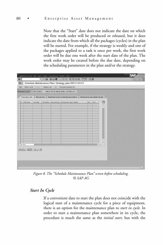
Note that the “Start” date does not indicate the date on whichthe first work order will be produced or released, but it doesindicate the date from which all the packages (cycles) in the planwill be started. For example, if the strategy is weekly and one ofthe packages applied to a task is once per week, the first workorder will be due one week after the start date of the plan. Thework order may be created before the due date, depending onthe scheduling parameters in the plan and/or the strategy.
Figure 8. The “Schedule Maintenance Plan” screen before scheduling.© SAP AG
Start In Cycle
If a convenient date to start the plan does not coincide with thelogical start of a maintenance cycle for a piece of equipment,there is an option for the maintenance plan to start in cycle. Inorder to start a maintenance plan somewhere in its cycle, theprocedure is much the same as the initial start, but with the
80 • E n t e r p r i s e A s s e t M a n a g e m e n t

addition of an offset. The offset indicates the amount of timeinto the cycle that the plan should be started.
Maintaining Maintenance Calls
Skipping Calls
In order to “skip” a call, which means that scheduled work willnot be performed, the specific call to be skipped must beselected on the “scheduled calls” list and the “Skip call” buttonnear the bottom of the screen must be clicked. Skipping a callmay not cause the next call to be rescheduled. If the next callmust be moved forward, it may be necessary to release the sub-sequent call manually.
Releasing Calls Manually
If it becomes necessary to release a call before its scheduled releasedate, a call can be manually release by selecting the call and click-ing on the “Release call” button near the bottom of the screen.
Manual calls can be viewed from this screen via the “Manual calls”tab.
Deadline Monitoring
Deadline Monitoring, formerly known as “Date Monitoring, ”may be used to produce one or many preventive maintenanceorders at once. The terms “Deadline Monitoring” and “DateMonitoring” are both misleading in that the functionality doesnot simply monitor calls and work orders. If not carefully used,Deadline Monitoring can produce and possibly release manywork orders by mistake.
Taking scheduling and control parameters into consideration, ifcalls are due within the number of days specified in DeadlineMonitoring, a work order will be created for each call duewithin that time period.
If security has not been implemented beyond the transactioncode level, it is possible to produce work orders for another
Ian McMullan • 81

planner group or even another plant intentionally or by mistake.If implementing SAP R/3 Plant Maintenance for more than oneplanner group or for more than one plant, security at the appro-priate levels is strongly recommended.
Deadline Monitoring is often used to group preventive mainte-nance calls and orders and is run on a regular basis, quite often as aregularly scheduled process, or “batch job.” It prevents the neces-sity of updating the scheduling of maintenance plans manually.
Work orders created must be released before any actual goodsissues or time (labor) confirmations can be charged to them. Ifwork orders are not configured to release upon creation, it maybe necessary to release work orders manually, including thosecreated by Deadline Monitoring.
Back to the Implementation Guide (IMG)—Maintenance Plans
The step-by-step discussion of the Plant Maintenance Maintenance Planssection of the implementation guide is continued below:
Basic Settings
Maintain Authorizations for Planning
Maintaining authorizations, a security function of the SAP R/3system, is best done in co-operation with the individual(s) whoseresponsibility it is to maintain security for the system. See the sec-tion “Security: Authorizations and Roles” for more information.
Define Plant Sections
This setting is typically used to represent individuals responsiblefor certain areas of a plant based on production responsibility.The intent is that, should a problem occur in a certain area ofthe plant, the person responsible can be determined and noti-fied. This IMG entry is a duplicate of entries in the “TechnicalObjects” and “Maintenance and Service Processing” areas.
82 • E n t e r p r i s e A s s e t M a n a g e m e n t

Define Maintenance Planner Groups
This setting is also a duplicate of settings in the “TechnicalObjects” and “Maintenance and Service Processing” areas. Amaintenance planner group may be composed of one or morepeople who have the responsibility for planning maintenancework. A maintenance planner group that has been defined for apiece of equipment, for example, will by default appear on workorders related to that piece of equipment.
Define ABC Indicators
One more duplicate of settings in the “Technical Objects” and“Maintenance and Service Processing” areas, The ABCIndicator field can be used as a means of categorizing equip-ment. There is no definite use for the field, but it is typicallyused to represent the importance or criticality of a technicalobject. Although the values A, B and C are provided by default,more may be added or any may be deleted as required.
Maintenance Plans
Set Maintenance Plan Categories
There is an entry in this configuration step for PlantMaintenance work orders to be generated from maintenanceplans, among other default settings. SAP R/3 versions from 4.5onward also allow the creation of notifications from mainte-nance plans. By default, the PM maintenance plan category willspecify that a PM maintenance plan will generate a maintenancework order. This can be changed here, if necessary.
Define Number Ranges for Maintenance Plans
This setting can be used to define a separate number range foreach of the previously mentioned maintenance plan categories,if desired. The maintenance plans created in each maintenanceplan category can be automatically or manually assigned a num-ber from the same number range or from different numberranges based on the settings made here. See the section titled
Ian McMullan • 83

“Number Ranges” for more information. Ensure that the num-ber range is large enough to permit the assignment of numbersto maintenance plans into the foreseeable future.
Define Number Ranges for Maintenance Items
Maintenance items, simply stated, provide a means of assigningmaintenance task lists to multiple objects based on the same sched-uling start date. At least one maintenance item is created for eachmaintenance plan, so the number range available for maintenanceitems should never be smaller than the number range provided formaintenance plans. If there is even a small chance that multiplemaintenance items will be assigned to a maintenance plan, thenumber range for maintenance items should be larger than that formaintenance plans to allow for the assignment of numbers tomaintenance items into the foreseeable future.
Define Sort Fields for Maintenance Plan
Here, methods of sorting and grouping maintenance plans may bedefined. The main advantage to providing sort fields for mainte-nance plans is to allow scheduling of multiple plans as a group inorder to save time. The alternative may be to perform the schedul-ing individually. Some thought may be required to provide someconvention or standard naming for the sort field values.
Define Field Selection for Maintenance Plan
When a list of maintenance plans is displayed, the settings heredetermine which maintenance plan fields are displayed, and inwhich order. As with other settings discussed previously, thefield identified as #1 will be displayed first, on the left side of thescreen displaying the list of maintenance plans. The field identi-fied as #2 will be displayed immediately to the right of field #1and so on. The numbers, as discussed previously, do not specifya position on the screen, just the order in which each field is dis-played from the left.
84 • E n t e r p r i s e A s s e t M a n a g e m e n t

Define Field Selection for Operation Data
As in the above setting, when a list of operations in the schedul-ing overview is displayed, this setting determines which fieldsare displayed by default, and in which order. Unless a specificfield is checked as “invisible, ” the user can still select whichfields to display on the scheduling overview. These settings pri-marily control the default display.
Set List Editing
The next several configuration settings allow the control anddefaults of selection criteria for the display of lists of mainte-nance plan and maintenance item data. Similar to “set list edit-ing” steps discussed previously, these settings can be saved as analternative to the default setting or in most cases can be saved asthe default setting.
Work Centers
A work center, from an SAP Plant Maintenance perspective, is usuallyone or more people. If a work center is comprised of more than one per-son, those people should be equally qualified. That is, it doesn’t matterwhich person is assigned to perform a task. In this way, several peoplewith equal qualifications can be grouped together and their combinedcapacity can be used to more effectively schedule work.
Work centers are assigned to cost centers, from where valid activities andactivity rates are derived. This is the source of planned and actual laborrates, multiplied by the number of hours, for example, that provides thecost of labor required to perform a task.
It is important to note that in the Production Planning module of SAP R/3,a work center is normally used to specify a place where work is performed,or to specify a machine that performs the work. In the Plant Maintenancemodule, a work center can also identify one or more similar machines thatare used to perform maintenance work. This can serve as an alternative todefining the machine as a PRT (Production Resources and Tools).However, a Plant Maintenance work center most often defines a person ora group of people.
Ian McMullan • 85

To determine whether the Plant Maintenance work center can define agroup of people, first determine if it matters which of the people in thegroup is assigned to perform a particular task. If only a particular personin the group can perform the task, it is likely that the person does notbelong to the work center.
For a group of people to belong to the same work center, it usually shouldnot matter which of the people in the group is assigned to a particular task.They should all be capable of performing similar tasks and they should allbe charged at the same labor rate to the work order, where applicable.
When configuring work centers, particularly the “Configure ScreenSequence for Work Center” step, remember that not all of the work cen-ter functionality and screens are relevant to Plant Maintenance. Forexample, if the “Technical Data” screen is active for Plant Maintenanceand some of its fields are required, this may cause problems for the per-son creating a Plant Maintenance work center. The person may findthemselves on the “Technical Data” tab, which is difficult to exit withoutlosing data if the required information is not available, which it may notbe for Plant Maintenance.
After the appropriate screen sequence has been defined, be sure to goback to the step described next, “Define Work Center Types and Link toTask List Application.” This ensures that the proper field selection andscreen sequences are assigned to the appropriate work center category.
When defining a work center (outside of the Implementation Guide), besure to enter data on the Capacity Header screen and its subscreens, ifapplicable, to ensure that the proper capacity has been defined for thework center. Otherwise, assigning the work center to work orders willcause a warning message stating that not enough resources are availableto perform the work. The Capacity Header screen can be accessed byclicking on the “Capacity” button near the bottom of the screen on the“Capacities” tab when creating or changing a work center. See Figure 9.
From the Capacity Header screen, the “Intervals and Shifts” button can beused to create a variety, or rotation, of shifts for the work center, if required.
86 • E n t e r p r i s e A s s e t M a n a g e m e n t

Figure 9. The “Change Work Center Capacity Header” screen.© SAP AG
A description of the Implementation Guide configuration steps for workcenters follows:
Define Work Center Types and Link to Task List Application
One primary function of this configuration step is to set thefields and screen sequences that are available when creatingwork centers. The Plant Maintenance work center category maydefault to the field selection and screen sequence for machines.Changing the field selection and screen sequence settings rele-vant to Plant Maintenance will help to present screens that bet-ter represent Plant Maintenance work center requirements.Whether the work center can be used in other applications mayalso be controlled here.
Ian McMullan • 87

Define Field Selection
This setting can be used to control whether fields relevant towork centers are input fields, display only fields, mandatoryinput fields, and so on. The field attributes can also be setaccording to the value of specific influencing field values. Forexample, if the work order category is specific to PlantMaintenance, some fields may be hidden. This allows the fieldsto be available for other work center applications, such asProduction, while being hidden for Plant Maintenance use.
Set Parameters
There is often no need to make changes to this configurationsetting for Plant Maintenance. The parameters defined here areused in the subsequent configuration step, Define Standard ValueKeys. This setting, along with the subsequent setting allow for stan-dard setup and teardown times, which are often more appropriatefor Production work centers than Plant Maintenance work centers.
Define Standard Value Keys
More often than not, the standard value key used for PlantMaintenance purposes is SAP0, which includes no parametersfrom the previous configuration step. If a standard setup, tear-down, or other standard value is to be considered in scheduling,a different standard value key, along with one or more parame-ters from the previous configuration step, may be used.
Define Employees Responsible for Work Centers
Define a person or group responsible for the maintenance ofwork center master data for each plant. If an individual is iden-tified, rather than a group, it may be beneficial to use a code,role, or position to represent the individual. Using an individ-ual’s real name will require maintenance of this setting when theindividual’s role changes.
88 • E n t e r p r i s e A s s e t M a n a g e m e n t

Create Default Work Center
A default work center may be useful in order to reduce theamount of time required to create multiple work centers. Priorto creating one or more default work centers, it may be evenmore beneficial to create a default capacity, which can providefurther default information to the default work center. Creatinga default capacity, if desired, can be found (in version 4.6C) inthe Implementation Guide (IMG) by following the menu pathProduction � Basic Data � Work Center � CapacityPlanning � Define Default Capacity.
Define Task List Usage Keys
This configuration step can be used to control the types of tasklists where a work center may be used. The default settings aremost often acceptable. A common work-around when configu-ration of task list usage 004 (Only maintenance task lists) is notadequate is to refer to task list usage 009 (All task list types)when creating a work center. If task list usage 009 is used, how-ever, the work center may be used in task lists in which it mightbe inappropriate.
Maintain Control Keys
There are several settings in this configuration step that controlwhether tasks related to the control key are relevant for schedul-ing, costing, capacity requirements, printing, confirmation, andso on. There are several default control keys relevant to PlantMaintenance. These begin with “PM” and in many cases maybe adequate. Add others, if necessary, but take care not to alteror delete other control keys that may already be in use, or maybe used in the future, by other SAP modules. When the systemis in use, the control key in Plant Maintenance is assigned to eachoperation of a work order or task list.
Ian McMullan • 89

Define Suitabilities
One or more qualifications may be defined here for later use todetermine whether a person is suitable or qualified to perform atask. This setting is specific to each plant.
Configure Screen Sequence for Work Center
There are several screens involved in the definition of a workcenter. This setting controls the order in which the screens arepresented as well as whether the screens are presented at all andwhether data entry on any given screen is mandatory. If achange to this setting does not appear to work properly, it maybe worth checking to see that the previous configuration step,Define Work Center Types and Link to Task List Application, isconfigured to the correct field selection and screen sequences.
Task Lists
Maintain Task List Status
For most basic uses of task lists in the Plant Maintenance mod-ule, the task list statuses provided as defaults are sufficient. ForPlant Maintenance purposes, only two of the default statuses arerequired, 1 (Created) and 2 (released for order). Do not deletethe other entries unless they will never be used by any othermodule, such as Production Planning. If there is a specific rea-son to create any additional statuses, they may be added here. Inusing the system, however, when searching for task lists, the sys-tem requires that a task list have the status of “2” to be found.Task lists with any other status cannot be found with the stan-dard list display functionality.
Define Task List Usage
In most cases, particularly for Plant Maintenance purposes, theSAP-provided defaults are acceptable here.
90 • E n t e r p r i s e A s s e t M a n a g e m e n t

Configure Planner Group
Individuals or groups responsible for task list planning are iden-tified here. This is not necessarily the same as planner groupsfound in other sections of the IMG. A setting made in one plan-ner group configuration step may not be carried over to anotherplanner group configuration step. At least one planner groupshould be defined for each valid plant. Unless used by anothermodule, such as Production Planning, the SAP default plannergroups (Planergruppe 1, for example) can be deleted.
Define Number Ranges for General Maintenance Task Lists
There is a separate number range for each of the task list types.This number range setting is to provide a range of numbers forgeneral maintenance task lists. This number range is not sharedwith any other SAP module or any other task list type. See thesection on number ranges for more information on configuringnumber ranges.
Define Number Ranges for Equipment Task Lists
This number range setting is to provide a number range forequipment task lists. This number range is not shared with anyother SAP module or any other task list type. See the section onnumber ranges for more information on configuring numberranges.
Define Number Ranges for Task Lists for Functional Locations
This number range setting is to provide a number range forfunctional location task lists. This number range is not sharedwith any other SAP module or any other task list type. See thesection on number ranges for more information on configuringnumber ranges.
Define Profiles with Default Values
At least two profiles should be configured for use with PlantMaintenance task lists. Two appropriate default profiles may be
Ian McMullan • 91
provided with the system. One profile should be configured foruse with primarily internally (employee) processed work and theother profile should be configured for use with primarily exter-nal (contract, for example). The profiles provide default valuesfor the creation of task lists. If fields are not filled in a profile,some field values may need to be entered when creating a tasklist header or in each operation of the task list. Likewise, if a pro-file is not referenced when creating a task list, some field valuesmay not be defaulted.
Define Presetting for Free Assignment of Material
This setting is normally acceptable as defaulted. There should bea “4” in the configuration table. This allows the free assignmentof materials to a BOM, etc.
Define Field Selection
This setting, not available in some version 4.6 releases and older,allows task list field attributes to be set. For example, specificfields can be set to be “display only, ” “required, ” “hidden, ” etc.There are numerous fields upon which the field attributes canbe influenced. For example, a specific field could be hiddenbased on the planning plant.
Maintain Control Keys
This is a similar setting to the maintain control keys setting in thework center section previously discussed. There are several set-tings in this configuration step that control whether tasksrelated to the control key are relevant for scheduling, costing,capacity requirements, printing, confirmation, and so on. Thereare several default control keys relevant to Plant Maintenance.These begin with “PM” and in many cases may be adequate.Add others, if necessary, but take care not to alter or delete othercontrol keys that may already be in use, or may be used in thefuture, by other SAP modules. When the system is in use, thecontrol key in Plant Maintenance is assigned to each operation ofa work order or task list.
92 • E n t e r p r i s e A s s e t M a n a g e m e n t

Maintain Suitabilities
Changes made in this configuration step affect the same table inSAP as changes made in the define suitabilities section underwork centers. One or more qualifications may be defined here forlater use to determine whether a person is suitable or qualifiedto perform a task. This setting is specific to each plant.
Define User Fields
Additional fields that are not already defined by the system maybe added in order to record additional data in the operations ofa work order. There are several different types of fields in orderto accommodate different types of data, such as character,numeric, date, etc.
The fields are given labels in the configuration step and theactual values associated with each label are assigned in the workorder. The use of the user-defined fields is not suitable forrecording readings during completion confirmation.Maintenance of the field values is performed during the creationor changing of a work order.
The user field functionality is shared among modules, particu-larly the PP (Production Planning) and SD (Sales &Distribution) modules, so coordinate definition of user fieldsbetween the modules according to the field key.
Set List Editing for Task Lists
This configuration setting allows the setup of variants to searchfor task lists. Although the standard system settings allow fortask list searching, it may be preferable to have several searchparameters predefined in order to save time repeatedly enteringthe same selection criteria when searching for task lists.
Presetting for List Display of Multi-Level Task Lists
Within this heading, there are settings for each of the lists thatmay appear when searching for task lists under the multi-leveltask list search. As with the other multi-level searches, when
Ian McMullan • 93

using the system, a group of check boxes representing objectsthat may be associated with task lists appears. To view the asso-ciated date, the check box for each object must be checked. Therelated data is then displayed with the task lists to which it isassociated. These configuration settings define which fields aredisplayed in the list for each of the associated objects. Thedefault settings are often a good starting point, but the defaultlist displays may be expanded or restricted as necessary. If a fieldis not displayed by default, the system user can still display thefield by selecting it in the display screen.
Production Resources/Tools
Define PRT Authorization Group
Production Resources and Tools master records may be pro-tected from changes by unauthorized users by using this setting.Standard SAP security does not provide security down to thelevel of individual objects unless authorization groups such asprovided in this setting are used. If protection at the object levelis not required, changes are not required here. The creation andchanging of PRT’s in general can still be protected with stan-dard SAP security by restricting access to the transactions thatallow the creation and changing of PRT master records.
If security is required at the object level, determine whichgroups of PRT records will be restricted to which groups ofusers (roles), and then define the authorization groups in thissetting. The authorization groups will then need to be assignedto the appropriate users/roles.
Define PRT Status
There are some default PRT statuses provided, which may beadequate. The PRT status controls whether a PRT can be usedat all, and whether it can be used for planning and/or produc-tion. Other statuses, if required, may be defined.
94 • E n t e r p r i s e A s s e t M a n a g e m e n t

Define Task List Usage Keys
There are several default task list usage keys. Although only oneor two of the keys are normally useful in the Plant Maintenancemodule, the others are useful for other modules, particularlyProduction Planning. For this reason, it is recommended not todelete any of the default task list usage keys. Task list types areassigned to the task list usage keys as part of this configuration.The only two keys that have the Plant Maintenance task list typesassigned to them are 004 (Only maintenance task lists) and 009(All task list types).
When creating a piece of equipment that is a PRT (ProductionResources and Tools), using transaction IE25 instead of transac-tion IE01, an extra tab containing PRT-specific fields will appear.One of the fields is the task list usage field. If the equipment is to beused for Plant Maintenance purposes, the task list usage must be004 or 009, if the default task list usage keys are used.
Define PRT Group Keys
Production Resources and Tools (PRT’s) can be grouped accord-ing to the groups defined in this configuration step. There maybe some group keys already defined, which can be deleted if theyare not useful. Note that PRT’s defined as equipment cannotmake use of this grouping. Searching for equipment PRT’sbased on the PRT group key cannot normally be performed.PRT’s defined as materials, however, can use the grouping.
Define PRT Control Keys
This setting is used to control whether a PRT is included in thefunctions of a task list or an order to which it is assigned. Anexample of one of the functions is scheduling. A PRT may beexcluded from such functions, if desired.
Formulas
The two settings contained in the Formulas heading are SetFormula Parameters and Configure Formula Definition. The first
Ian McMullan • 95

step is used to define formulas that are used or combined in thesecond step. The assignment of a PRT can be as exact and ascomplex as desired and with these settings, set up time, teardown time and numerous other factors affecting capacity plan-ning and costs may be set. If such detailed tracking is notrequired, accept these settings as they are defaulted. Even if suchformulae are required, examine the default formulas first. Theformula required may already be defined.
Service Contracts
Set List Editing for Service Contracts
This setting is usually only relevant for Customer Service func-tionality, but it controls the list editing displays for informationrelated to service contracts. This configuration step is similar to theother configuration steps involving the definition of list editing.
The Work Order Cycle
The complete work order cycle in the SAP R/3 system includes notifications,work orders, assignment of labor, assignment of materials, completion con-firmation (possibly involving the Cross-Application Time Sheet, CATS), set-tlement, and business completion of the work order. The cycle may extend tothe analysis of reactive maintenance work so that preventive maintenance canbe scheduled to reduce the amount of reactive/breakdown maintenance.
Although, technically speaking, it is possible to use work orders without noti-fications, or notifications without work orders, in the R/3 Plant Maintenancesystem, to omit either will mean a loss of information. Notifications canmaintain statistical information, such as mean-time-between-failures, thatcan be important in reducing breakdown maintenance work. Work ordersmaintain the essential integration with other modules, including cost infor-mation. In addition, the relationship between notifications and work ordersprovides a method for approval of requested work.
Determine, along with controlling and/or finance personnel, the method bywhich work orders will be settled. SAP allows work orders to be settled to avariety of receivers, including cost centers, projects, internal orders, otherwork orders, and so on. If equipment has been assigned to the appropriate
96 • E n t e r p r i s e A s s e t M a n a g e m e n t

cost centers, for example, work orders created for that equipment would, bydefault, settle to those cost centers.
Notifications
A notification in the SAP R/3 system is typically used to notify someonethat some work is required, is requested, or was already done. Thosethree typical uses define the three default notification types for PM,although other notification types are available for QM (QualityManagement) and CS (Customer Service), formerly SM (ServiceManagement). Non-PM notification types should not be deleted with-out determining that other modules will never use them.
Notifications, in addition to the functionality listed above, track andcompile statistical information and history regarding the objects againstwhich they were created. A notification, however, retains no cost infor-mation and has no significant integration with other modules.
A malfunction report notification is, as the name suggests, a report that amalfunction has occurred. Usually, a malfunction report is used where itmight be beneficial to record breakdown information such as mean-time-between-failures or mean-time-to-repair. The relevant piece of equipmentmay be completely stopped or its performance may be reduced.
A maintenance request notification is usually used to request maintenancework on a piece of equipment that may be functioning satisfactorily, butwhose operator, for example, may see a potential problem.
An activity report notification is normally used to record work that hasalready been performed in order to maintain complete statistical historyfor the relevant equipment.
Although other notification types may be defined, the majority of imple-mentations should find that the three default notification typesdescribed above would suffice. Since notifications can be identified asassigned to a particular plant, there is certainly no need to create differ-ent notification types for each plant, nor is there any need to speciallynumber (“smart” number) the notifications for each plant.
The historical information recorded through the use of notifications isbest done with the use of catalogs, which are described in the section oncatalogs, below.
Ian McMullan • 97

Catalogs
In the SAP R/3 system, catalogs represent a method of providing stan-dard codes for damage, cause of damage, activities, and so on. Theadvantage of using standard codes and descriptions instead of allowingfree-form descriptions is that when the information is summarized, it ispossible to see how many times a particular problem has occurred with aparticular piece of equipment within a specific time frame and howmany times each maintenance activity was performed to resolve theproblem. Further analysis allows the tracking of problems to a particularmanufacturer, if manufacturer data is recorded for equipment. Withoutstandard codes it would be difficult, at best, to summarize such informa-tion into a usable format.
A catalog profile provides a means of grouping catalog codes that are rele-vant to a particular function, for example. The codes within a catalogprofile are made available to notifications based on the object (piece ofequipment, for example) against which the notification is written. If apiece of equipment has a catalog profile assigned to it, only the codeswithin that catalog profile will be available to notifications written forthat piece of equipment. A catalog profile, therefore, can be a method ofreducing the number of codes to those relevant for an object.
Within a catalog profile are code groups, which can be used to furtherreduce the quantity of codes from which to choose. Codes can begrouped into equipment types, for example, so that the types of damagefor pumps are contained in a separate code group than the types of dam-age for motors. The two main factors for separating the codes are:
• to avoid the use of codes that are not relevant to the object, and
• to restrict the choices to a manageable number. The morechoices available in a list, the longer it will take to make a choiceand the chance of a wrong choice being made will increase.
Finally, the codes within each code group are defined. Ensure that the codesare relevant to the group. Ideally, the number of code groups from which tochoose should be minimized, as should the number of codes within eachcode group. In some situations, particularly where the use of codes is regu-lated, it may not be possible to minimize the number of codes.
For Plant Maintenance purposes, the catalogs typically used are damage,cause of damage, object part, activities, tasks, and sometimes coding. Other
98 • E n t e r p r i s e A s s e t M a n a g e m e n t

catalogs, if required, may be defined, but bear in mind that the catalogcode can only be one character or digit. Since SAP reserves the right touse all the digits and the characters A to O inclusive, only the codes P toZ may be used to define other desired catalogs.
The information accumulated on notifications by means of using cata-logs can be reported using the Plant Maintenance Information System(PMIS), a subset of the Logistics Information System (LIS), which isdescribed in a later section.
Work Orders
A work order in the SAP R/3 system is typically used to plan work that isrequired, assign the work to resources who will perform the necessary work,accumulate labor and material costs, and track completion of the work.
A sequence of tasks (or operations) can be included on the work order.Labor and materials that will be required to complete the work aredefined on the work order while it is in the planning stage. This providesplanned labor and material costs.
If planned materials are purchased independently of work orders and arekept in stock, the work order will generate a reservation for such materi-als. If planned materials are not kept in stock and must be purchasedspecifically for the work order, the work order will generate a purchaserequisition for such materials.
Planned labor can be performed by internal resources (employees) or byexternal resources (contractors). This will be discussed in more detail later.
During completion of the work, goods (materials) are issued to the workorder, which causes actual material costs to accumulate on the workorder. Confirmations of labor, either through the Human Resourcesmodule or directly in the Plant Maintenance module, cause actual laborcosts to accumulate on the work order.
The three basic steps to complete and close a work order consist of tech-nical completion, which usually indicates that all of the work has beencompleted, settlement, during which the accumulated costs on the workorder are settled to a cost center or other cost receiver, and business com-pletion (close).
Ian McMullan • 99

A work order in SAP R/3 can be generated from a notification, it can becreated independently, or it can be generated from a maintenance plan.
As with notifications, there are several work order types provided withthe R/3 system by default. Many find that the default work order typesare adequate for their needs, but additional order types can be defined ifrequired. Since work orders can be identified by plant, there is no needto “smart” number the work orders to identify them by plant.
Unless there are circumstances requiring that work orders be manuallynumbered, it is usually recommended that the system assign work ordernumbers automatically. This is referred to as “internal” numbering. Seethe section on “Number Ranges” for further information.
Back to the Implementation Guide (IMG)—Maintenance and Service Processing
The step-by-step discussion of the Maintenance and Service Processingsection of the implementation guide is continued below:
Basic Settings
Maintain Authorizations for Processing
Maintaining authorizations, a security function of the SAP R/3system, is best done in co-operation with the individual(s) whoseresponsibility it is to maintain security for the system. See the sec-tion “Security: Authorizations and Roles” for more information.
Planning of Background Jobs for PDC
PDC, Plant Data Collection, can be used to automaticallyupdate information in the SAP system, possibly saving time andeffort entering repetitive data into the SAP system. However,since there is more than one specific method by which toaccomplish the automation, it is not possible to determinebeforehand what these settings should be. The third-party datacollection system and the method by which it will be interfacedwith the SAP system will determine what the settings in thisconfiguration step will be.
100 • E n t e r p r i s e A s s e t M a n a g e m e n t

Since there may be some significant time involved in gettingtwo systems to “talk” to each other and transfer data reliably,ensure that the scope of the implementation includes the inte-gration of a plant data collection system and SAP R/3.
Define Download Parameters for PDC
As with the previous configuration step, this step also relates to theautomatic collection and transfer of data from an external systemto the SAP R/3 system. If this is required, work closely with thedevelopers or programmers to determine how these settings shouldbe set to meet the needs of the Plant Maintenance module in rela-tion to the methods used to interface the two systems.
Define Plant Sections
This setting is typically used to represent individuals responsiblefor certain areas of a plant based on production responsibility.The intent is that, should a problem occur in a certain area ofthe plant, the person responsible can be determined and noti-fied. This IMG entry is a duplicate of entries in the “TechnicalObjects” and “Maintenance Plans” areas.
Define Planner Groups
This setting is also a duplicate of settings in the “TechnicalObjects” and “Maintenance Plans” areas. A maintenance plan-ner group may be composed of one or more people who havethe responsibility for planning maintenance work. A mainte-nance planner group that has been defined for a piece of equip-ment, for example, will by default appear on work orders relatedto that piece of equipment.
Define ABC Indicators
One more duplicate of settings in the “Technical Objects” and“Maintenance Plans” areas, The ABC Indicator field can be usedas a means of categorizing equipment. There is no definite usefor the field, but it is typically used to represent the importance
Ian McMullan • 101

or criticality of a technical object. Although the values A, B andC are provided by default, more may be added or any may bedeleted as required.
Define Shop Papers, Forms and Output Programs
This configuration step controls which shop papers, such asnotifications and work orders, are available for printing. Withinthe configuration step, shop papers specific to notifications maybe defined as well as shop papers specific to work orders. If acustom work order print form has been developed, that formmust be defined in this configuration step (or another similar,later configuration step) in order to be available for printing.
Define Printer
This heading consists of three settings as follows:
� Set User-Specific Print Defaults. If a specific user (or amember of a specific planner group or planning plant)requires a different default printer, language, number ofcopies, etc., these settings may be made here.
� Define Print Diversion. If a specific shop paper must beprinted on a different printer than the default printer,perhaps because it contains sensitive information, thesetting for a different printer may be made here.
Print Diversion According to Field Contents
If a specific printer must be used, depending on the value of aparticular field, then that setting may be made here.
Activate Printing in Online Processing
It may be necessary, during the programming of shop papers, totest the functionality during online processing rather than fromthe update program. The setting to do so may be made here.This setting should be made individually in the instance (sys-tem) in which the testing is required, and the setting should not
102 • E n t e r p r i s e A s s e t M a n a g e m e n t

be transported. The checkbox should not be checked in the pro-duction system.
Download
The two settings contained in this heading, “Define Destinationand Database for PC Download” and “Download Structures toPC, ” are used to define the method by which notificationsand/or work orders (shop papers) may be downloaded to aMicrosoft Access database. The online documentation in theImplementation Guide provides further information. Note that,since this setting is grouped under Print Control, The downloadof a notification or a work order is considered a printout and, assuch, the status of the notification or work order will indicatethat it has been printed.
General Order Settlement
This group of configuration steps should not be changed with-out the involvement of CO (Controlling) or FI/CO personnel.This section is a duplicate of that found in CO configuration, soany changes made here will be reflected in the CO module.
Maintain Settlement Profiles
This setting provides some integration with the CO (Controlling)module in the R/3 system. Although there are some reasonabledefaults provided by SAP, review the defaults to determine whetherany changes are required. The default settlement profile most oftenused by the PM module is “40—Maintenance measure.” Do notmake changes to, and do not delete, any of the other settlementprofiles without consulting with a person responsible for the con-figuration or maintenance of the CO module or any other modulethat may be affected (such as those responsible for the QM(Quality Management) module in the case of “70—QM order”).
In the default settlement profile 40, for example, it is presumedthat work orders will be settled. If, for some reason, work orders arenot to be settled, the provision for this is contained here. Thedefault object type is “CTR, ” which is a cost center. This presumes
Ian McMullan • 103

that the majority of Plant Maintenance work orders will be settledto a cost center. If this is not the case, the default settlement objecttype can be changed here.
Among the other settings contained here is a list of validreceivers. This determines whether the user may (or must) settlethe work order to types of receivers. While in the majority ofcases the receiver may be a cost center, orders can also be settledto a fixed asset, where work performed on the asset may increasethe value of the asset, or the settlement may be made to a WBSelement, where the work performed in the work order pertainsto a Work Breakdown Structure element in a project in the PS(Project Systems) module. Other receivers may be allowed ordisallowed as required.
Maintain Allocation Structures
This setting allows the assignment of costs to receiver types.Once again, this setting should only be changed by, or after con-sulting with, a person responsible for the CO module.
Maintain PA Transfer Structure
This setting allows the definition of cost allocation related toprofitability analysis. This is mostly related to sales orders andprojects and should only be changed by, or after consultingwith, a person responsible for the CO module.
Assign Value Fields
These value fields are assigned to the PA Transfer Structure. Ifno changes were made to the PA Transfer Structure in the previ-ous configuration step, then no changes are likely to be made inthis configuration step. If changes are required, allow a personresponsible for the CO module to make the changes, or do itafter consultation with that person.
104 • E n t e r p r i s e A s s e t M a n a g e m e n t

Define Number Ranges for Settlement Documents
Do not change this setting unless you are also responsible for theconfiguration of the CO module. It is unlikely that any PlantMaintenance requirements would require a change to the num-ber ranges for settlement documents.
Settings for Display of Costs
This group of configuration steps is relevant to the PlantMaintenance Information System (PMIS) and, if applicable, theCustomer Service Information System (CSIS).
Cost elements are used to group costs related to a specific purpose,internal labor for example. A value category can be defined (theR/3 system has a few defined by default) to reflect one or more costelements. For example, if internal labor costs are actually reportedthrough several cost elements, those cost elements can be groupedinto a value category, perhaps called “Internal Labor.”
Value categories can display the breakdown of costs in the cost dis-play of a work order and are also used to report costs in the PMIS.
Maintain Value Categories
This setting simply allows the definition of value categories, andwhether they are related to costs or revenues. Keep in mind,when defining value categories, that they may also be used bythe Project Systems (PS) module.
Assign Cost Elements to Value Categories
Cost elements may be assigned to the appropriate value cate-gories here. It may be necessary to work with personnel repre-senting the CO module to determine the cost elements thatmake up a value category, although the CO representatives maybe unfamiliar with the term “value category.” Either one costelement or a range of cost elements can be assigned directly to avalue category. If the appropriate cost elements have not beennumbered sequentially, that is, there may be inappropriate costelements in between the relevant cost elements, the appropriate
Ian McMullan • 105

cost elements must be grouped in a cost element group. Thecost element group can then be assigned to the value category.The creation of cost element groups, if required, is usually per-formed in the CO module.
Check Consistency of Value Category Assignment
After configuring value categories and assigning cost elements tothe value categories, this step can be used to evaluate the assign-ments. It is not restricted to Plant Maintenance-specific assign-ments, so it may take a few minutes to run, depending onseveral factors. Use this analysis to determine whether anyappropriate cost elements have not been assigned, that theappropriate cost elements are assigned properly, and that costelements have not been assigned more than once (unlessintended, for some reason).
Define Version for Cost Estimates for Orders
This setting allows cost estimates to be entered for value cate-gories on work orders. There is usually no need to change thedefault setting that was provided. In any case, only one cost esti-mate version can be maintained here.
Define Default Values for Value Categories
This setting controls the value categories that are displayed bydefault on the “Costs” tab within the “Costs” tab (yes, they bothhave the same name) on a work order. Other categories may beadded when viewing the actual work order.
Quotation Creation and Billing for Service Orders
This group of configuration steps is related to Customer Service(formerly Service Management) and is not covered here.Nothing in this group is required for configuration of non-Customer Service Plant Maintenance.
106 • E n t e r p r i s e A s s e t M a n a g e m e n t
Maintenance and Service Notifications
Overview of Notification Type
This item contains numerous options related to notifications.However, the following two sections, “Notification Creation”(beginning on page109) and “Notification Processing” (begin-ning on page 119) are best completed before reviewing theoptions in this step. The options contained here are based onsome of the settings available in the following sections.
The options available in this configuration item are as follows:
� Screen Areas in Notification Header. This allows the def-inition for the basic layout and information in the noti-fication header. With this option, it is possible toprovide a notification layout suitable for maintenancenotifications, service notifications (CS module), orquality notifications (QM module). It is also possible torestrict the type of object (functional location, equip-ment, and/or assembly) for which the notification iscreated. In addition, certain custom-defined screenareas can be assigned to the notification type.
� Screen Structure for Extended View. This option allowscontrol over which tabs appear on a notification, based onthe notification type. Further, by selecting a tab and click-ing the magnifying glass icon (“Details”), specific screenareas (groups of fields) can be assigned to a tab, deletedfrom a tab, or the order of screen areas on a tab can bechanged. The name of the tab can be changed and anicon can be assigned to the tab. Any particular tab can bemade active or inactive by using the checkbox.
� Screen Structure for Simplified View. This option can beused to defined a simple notification screen, usuallywith no tabs, and containing only the screen areas(groups of fields) that are entered here. In a later con-figuration step, “Defined Transaction Start Values, ” thesimplified view can be assigned instead of the extendedview to a specific transaction (Create, Change, orDisplay). This setting is also based on notification type.
Ian McMullan • 107

� Catalogs and Catalog Profiles. Specific catalogs, whichusually define damage, cause, activities, etc. availablefor notifications, can be assigned to the notificationtype here. Different sets of catalogs may be defined fordifferent types of notifications. Catalog definition canbe performed in the Implementation Guide under the“Notification Content” section, or outside of theImplementation Guide.
� Format Long Text. Long text control can be managedhere. There is an option to log changes to long text innotifications as well as an option to prevent changes tolong text in notifications. In addition, formatting oflong text can be forced through the other options onthis screen, which may be more of interest if long text isexported to other applications outside of SAP.
� Priority Type. There may be more than one priority type(which is not the same as priority level) defined in thesystem. For example, one priority type might apply towork orders, while another priority type might apply tonotifications, or one type for maintenance notificationsand another type for service notifications. Each prioritytype may contain a different set of priorities than otherpriority types. For example, the priority type for main-tenance notifications might have only 1 to 3 (high,medium, and low) defined, while the priority type forservice notifications might have 1 to 4 (emergency,high, medium, low) defined. This option allows a singlenotification type to be assigned to a notification type.
� Partner Determination Procedure. The SAP R/3 systemis delivered with a default partner determination proce-dure for PM. Unless a different partner determinationprocedure has been defined for Plant Maintenance use,the setting here should be “PM” for PlantMaintenance-related notification types.
� Partner Functions, Approval. This option contains settingsthat can be used to control an approval process for a noti-fication type. Partners can be defined for responsibility,
108 • E n t e r p r i s e A s s e t M a n a g e m e n t

and links to workflow processes can be defined (ifWorkflow is being used). There is a checkbox that shouldnot be checked if an approval process is not required fornotifications.
� Standard Output. Also referred to as “Standard text, ”this option can be used to define text that shouldappear on notifications by specifying the code of thestandard text. This is particularly useful when printingnotifications (or later, for work orders). Standard textitself is not defined within the Implementation Guide,but is defined in the SAP system in the menu Tools �Form Printout � SAPScript � Standard Text
� Status Profile. If user-defined statuses are to be used(and have already been defined) in addition to systemstatuses for notifications, the profile for the appropriatestatuses can be specified here, for both the notificationitself as well as for tasks in the notification, if required.User statuses, discussed later, can be defined when theSAP-provided system statuses are not sufficient.
� Response Time Monitoring. Used primarily for CustomerService, if response monitoring has been defined, thisoption can be used to assign a response profile to a noti-fication type.
� Allowed Change of Notification Type. This option can beused to specify whether a notification can be changedfrom one notification type to a different notification type,and to specify the original notification types and targetnotification types for which this action will be permitted.
Notification Creation
This group of configuration steps consists of information relative to thecreation of a notification.
Ian McMullan • 109

Define Notification Types
Three Plant Maintenance-related notification types are deliv-ered by default with the SAP R/3 system. These are:
� Breakdown Report. This notification type provides ameans to report that an object, such as a piece ofequipment, has broken down or failed in some man-ner. Usually, mean-time-between-failure and mean-time-to-repair statistics are associated with this typeof notification.
� Maintenance Request. This notification type provides ameans to request maintenance, often for a non-break-down situation, although the “Breakdown” indicator isstill available.
� Activity Report. This notification type is often used toreport activity that has already been performed, inorder to track statistical history. Because the activitymay have already been performed, this notification typeis sometimes created from a work order, while workorders are often created from the other two defaultnotification types.
While additional notification types can be created in this configurationstep, it is often found that the original three notification types deliveredwith the R/3 system by default are adequate for Plant Maintenance.Note that there are additional notification types for Customer Service(Service Management) and Quality Management.
Set Screen Templates for the Notification Type
This configuration step allows some flexibility in the way that anotification screen is organized and in which data it includes.
At least a notification type must be specified in the initial win-dow that is displayed. The resulting screen will display anoverview of the information that the notification type currentlycontains on its screen.
Those items whose “Register” begins with a 10 will appear astabs on the main notification screen for that notification type.
110 • E n t e r p r i s e A s s e t M a n a g e m e n t

Items whose “Register” begins with a 20 appear as tabs withinthe “Items” tab in the system as delivered.
A tab (register, in this case) can be selected, and its settingsviewed, by using the “Details” (magnifying glass) icon. The titlefor that tab can be changed from this screen and, if desired, anicon can be added to the tab in addition to, or instead of, the tabdescription.
Some tabs consist of screen areas that can be changed. A screenarea consists of fields that are usually grouped on the screen,often within their own “box.” On some tabs, these screen areasare set and cannot be changed. On tabs where the screen areascan be changed, it is possible to remove groups of fields entirelyfrom the tab, add other screen areas to a tab, or move screenareas from one tab to another. There are restrictions, however,on which tabs to which screen areas can be moved.
Each tab contains a checkbox which, when checked, activatesthat particular tab. When the checkbox is not checked, that tabwill not appear for that notification type. So, it is possible forsome tabs and screen areas to appear for one notification type,but not another.
Define Long Text Control for Notification Types
In addition to the short, 40 character field available to describe anotification, a “long text” field is available for longer descrip-tions. The primary purpose of this configuration step is to eitherprevent changes to the long text of a notification type or to logany changes to the long text of a notification type.
Set Field Selection for Notifications
As with the other configuration steps that address field selec-tion, this step allows fields on the notification screen to be hid-den, highlighted, display only, and so on. The fields can havedifferent attributes, if desired, based on notification type, prior-ity, or several other “influencing” values.
Ian McMullan • 111

With the ability to change field attributes combined with the abil-ity to change screen areas (groups of fields), a considerable amountof manipulation is possible with the notification screens.
Define Number Ranges
See the section on Number Ranges for more details regardingnumber ranges.
This configuration step allows the assignment of number rangesto notification types. It is possible to assign every notificationtype to the same number range, it is possible to assign each noti-fication type its own number range, and it is also possible tocombine notification types into number ranges.
As with other number ranges, internal (system assigned) andexternal (user specified) number ranges can be defined.Generally, external number ranges for notifications are discour-aged, particularly where multiple people will be using the sys-tem, although there are always exceptions. A couple of reasonsto let the system assign numbers to notifications are that it takesmore time to enter a number than to let the system do it, and itcan be difficult to determine the next valid number if more thanone person is responsible for creating notifications.
The overall notification number range is shared with the QM(Quality Management) and CS (Customer Service) modules.Consider the requirements of those modules, whether they areused now or ever may be used in the future, when defining noti-fication number ranges.
If several ranges are to be defined, ensure that the quantity ofnumbers is much more than adequate. Consider possibilitiessuch as the acquisition of additional plants, etc. If there is eventhe slightest doubt, spread out the number ranges to allowexpansion, if ever required.
The use of the configuration step is not necessarily intuitive.Define the number ranges first. To assign a notification type to anumber range, double-click on the notification type(s), selectthe number range (check the box), and then click the“Element/Group” button.
112 • E n t e r p r i s e A s s e t M a n a g e m e n t

Define Transaction Start Values
When a transaction is performed to create, change or display anotification, a specific screen appears first, along with a sug-gested notification type. This configuration allows the defaultscreen and notification type to be changed, if required. Thedefault values are often acceptable for this setting.
Assign Standard Texts for Short Messages to Notification Types
This configuration step is completely optional. It is possible todefine a “standard text” for each notification type. This standardtext can be used on notifications of that type simply by specify-ing the code for that standard text, instead of having to type theentire text each time it is required. The standard text obviouslymust be defined before it can be assigned to a notification type.
The standard text itself is defined elsewhere, not in theImplementation Guide, but in the standard SAP Easy Accessmenu under Tools � Form Printout � SAPScript � StandardText. Note that in versions of R/3 earlier than Enterprise (4.7), themenu path will likely differ from that shown here.
After any standard texts have been defined, this configuration stepcan be used to assign the standard texts to notification types.
Allowed Change of Notification Type
This configuration step can be used to specify that a notificationcan be changed from one notification type to another. Onlythose changes will be permitted that are specified here.
Assign Notification Types to Order Types
This configuration step can only be performed after order typeshave been defined, which occurs a little later in theImplementation Guide.
Once order types have been defined, this configuration step canbe used to associate notification types with a default work order
Ian McMullan • 113

type. This is not a restriction, but can save a small amount oftime when creating a work order from a notification.
Define Order Types and Special Notification Parameters
This configuration step is only relevant to Customer Service(Service Management) module notifications. It allows a salesorder to be created from a service notification and is notrequired for non-Customer Service-related notifications.
Notification Content
This group of configuration steps consists of information relative to cata-logs, their contents, and how they are related to notification types. Catalogscontain information relative to damage, cause of damage, activities, etc.
Maintain Catalogs
Catalogs are used to encourage the recording of informationthat can be analyzed later. The information gathered throughthe use of catalogs is best analyzed over a period of time(months, for example) and the Plant Maintenance InformationSystem, discussed later, provides a means of reporting the infor-mation. The information recorded can be used to identify pat-terns of damage, cause of damage, maintenance costs associatedwith types of damage, maintenance costs associated with a par-ticular manufacturer’s equipment, and so on.
The SAP R/3 system as delivered contains several catalogs bydefault. In most cases, these catalogs are sufficient, but their con-tents are not. A catalog has been predefined for each of the catalog-related fields that usually appear on the notification screen.
If the temptation to create additional catalogs arises, be advisedthat the catalog ID field is limited to one character, and SAP hasreserved the characters A through O as well as the digits 0through 9. That leaves only 11 possible additional catalogs thatmay be defined. Work with the default catalogs, if possible,before attempting to define other catalogs.
114 • E n t e r p r i s e A s s e t M a n a g e m e n t
Creating and editing catalogs can also be performed outside of theImplementation Guide. SAP recommends that the creation andediting of catalogs be performed in the productive system ratherthan being transported to the productive system. Currently, how-ever, it is still possible to perform this step either in theImplementation Guide or outside the Implementation Guide, andmanually transport the catalogs individually. That means that,while editing a specific catalog, the menu Table View �Transport can be used to generate a change request for transport.More information regarding transporting configuration can befound in the “Implementation Guide” section on page 10.
Although the creation of catalogs, code groups and codes can beperformed outside of the Implementation Guide, the followingsteps, “Define Catalog Profile” and “Change Catalogs andCatalog Profile for Notification Type, ” must still be performedin the Implementation Guide.
With the delivered SAP R/3 system, the following catalog codesare most relevant to Plant Maintenance:
� A—Activities
� B—Object Parts
� C—Overview of Damage
� D—Coding
� 2—Tasks
� 5—Causes
Some of the other default catalogs are more relevant to QM(Quality Management) module use. However, other existingcatalogs can be configured for use with Plant Maintenance noti-fications and, as previously discussed, a limited number of addi-tional catalogs can also be defined if required.
With a little imagination, some other uses can be discovered andinvented for using catalogs, code groups and codes. This discussionwill be limited to those catalogs listed above and for basic purposes.
The Activities catalog should usually contain a list of activitiesthat could have been performed to repair a piece of equipment,solve a problem, etc. For example, “Welded, ” “Rewound, ” and
Ian McMullan • 115

“Replaced” are activities. The activities can be grouped asdesired. An example of an activity grouping is to arrange thevalid activities for a specific type of equipment into a group thatreflects that equipment type.
The Object Parts catalog can be used to contain sections, parts,or areas of a piece of equipment for which to track damage andcause. If there is an interest in keeping track of damage to (orbecause of ) a part of a piece of equipment, a list of Object Partscan be maintained. Often, the grouping of Object Parts is by thetype of equipment, since the parts will vary depending on theequipment type. Note that Object Parts should not be confusedwith replacement parts, spares, parts used to repair the equip-ment, and so on, although there may be some overlap. This fieldis not used to keep track of the parts that were used during themaintenance of a piece of equipment.
The Overview of Damage catalog usually contains a list of possi-ble damages. Examples of damage could be “Bent, ” “Cracked, ”“Melted, ” and so on. There are different methods of groupingdamage codes. The best method of grouping damage codes willvary, depending on ease of use and the needs of the business.One example of grouping damage codes is, once again, by typeof equipment.
The Tasks catalog is sometimes not used, since its most appro-priate use is to provide a sequence of steps to perform therequired or requested maintenance. Since, for many SAP R/3Plant Maintenance implementations, the required sequence ofsteps is contained in the work order itself, entering a sequence ofsteps in the notification may be redundant. Of course, there areexceptions, and for some implementations, the Tasks catalogmay be beneficial and even required, especially if the PlantMaintenance system is to be used without work orders. On theother hand, maintaining a catalog for tasks enables the creatorof the notification to identify steps to be performed from a stan-dard list. This can, where appropriate, save some time. If used,the Tasks catalog could, in some cases, almost match theActivities catalog, except for the “tense” (future tense, past tense)of the catalog entries. For example, the Tasks catalog could con-tain the entries “Weld, ” “Rewind, ” and “Replace, ” while the
116 • E n t e r p r i s e A s s e t M a n a g e m e n t

Activities catalog could contain the entries “Welded, ”“Rewound, ” and “Replaced.” Again, the catalog can be groupedas best suits the requirements of the implementation.
The Causes catalog can be used to contain a list of the possiblecauses of damage. Some examples of causes of damage could be“Impact, ” “High Temperature, ” “Vandalism, ” and so on.Causes can be grouped in a number of ways, including by typeof equipment.
Three of the basic catalogs are used on the standard notificationscreen in the “Item” screen area (this being on the notificationtransaction screen while creating, changing, or displaying a noti-fication, not in the Implementation Guide). These are the“Object part, ” “Damage” and “Cause” catalogs.
The two fields beside each of those catalogs are for a code groupand a code, respectively. Ideally, the three fields, “Object part, ”“Damage, ” and “Cause” will flow together to make a sentence.For example, the casing (Object part) was cracked (Damage)because of an impact (Cause).
It is important to note that the catalog/code structure is notexactly hierarchical. The codes for each catalog are arranged bycode groups, but additional levels or groupings (groups ofgroups, for example) are not possible.
Ideally, it might be desirable to plan and organize the groups andcodes in such a way that the list of groups would be short enoughto all appear on the screen without scrolling and, likewise, the listof codes in each group would be short enough to all appear on thescreen without scrolling. However, real-life requirements oftenovershadow convenience. Try to provide enough codes for mean-ingful reporting and analysis, but not so many that it is difficult forthe user to select the most appropriate code.
Display Catalog Directory with All Sub-Items
There is nothing to configure here. This step simply provides anoverall view of the catalogs, groups and codes selected.
Ian McMullan • 117

Define Catalog Profile
Catalog profiles can be assigned to functional locations, equip-ment and other objects. This configuration step provides ameans of assigning a different selection of codes to differenttypes of equipment, for example.
If two different sets of code groups had been created, one groupwith the code group ID beginning with “PM” (PM0001,PM0002, etc.) and the other with the code group ID beginningwith “QA” (QA0001, QA0002, etc.), the PM code groups canbe assigned to a PM catalog profile and the QA code groups canbe assigned to a QA catalog profile. The appropriate catalogprofile can then be assigned to the appropriate pieces of equip-ment or other object. A notification created for a piece of equip-ment will inherit the catalog profile assigned to that piece ofequipment (or from the notification type), so when the damage,cause and other codes are accessed, only the codes relevant tothat catalog profile will be displayed.
This configuration can also be used by the QM (QualityManagement) module and the CS (Customer Service) module,so assign the appropriate code groups to at least one relevantPlant Maintenance-related catalog profile.
Change Catalogs and Catalog Profile for Notification Type
In this configuration step, the appropriate catalog profile previ-ously created can be assigned to one or more notification types.In addition, the appropriate catalogs can be assigned to notifica-tion types. If a different catalog was previously defined for a spe-cific use, the catalog can be associated with one or more specificnotification types here. Any catalogs that are definitely notdesired on the notification screen can be removed here.
In Summary:
� Determine which catalogs to maintain (Object part,damage, cause, tasks, activities).
� Create a selection of groups and codes for each catalog(can take some time).
118 • E n t e r p r i s e A s s e t M a n a g e m e n t

� Assign the catalogs and groups to one or more catalogprofiles.
� Assign the catalogs and profiles to notification types
Define Partner Determination Procedure and Partner Function
In SAP terminology, a partner is an entity that can be associatedwith an object in any way. In this instance, the object is a notifi-cation. For most implementations, the default settings for thisconfiguration step will provide the required functionality.
Regardless of whether changes are made to partner determina-tion procedures, review this configuration step to ensure thatthe PM (Plant Maintenance) partner determination procedure(or a different partner determination procedure, if more appro-priate) is assigned to the relevant PM-related notification types,particularly if additional notification types have been defined.
Review the partner functions that have been assigned to thenotification types if changes are required. If desired, an approvalprocess can be assigned to notifications. To use the approvalprocess function, check the “Approval required” checkbox andpress the “Enter” key on the keyboard. The additional fields willappear. Do not check the “Approval required” checkbox if thistype of approval process is not required.
Field Selection for List Display of Partner Data
This configuration section can be used to control which dataappears in lists of various partners. For example, when a list ofvendor data is displayed, the vendor-relevant fields that appearare those specified in this configuration setting. Some defaultsare provided.
Notification Processing
This group of configuration steps consists of information relative to theprocessing of a notification.
Ian McMullan • 119

Response Time Monitoring
This configuration section is more suited to use with the CS(Customer Service) module rather than with standard PlantMaintenance functionality.
The first setting, also found elsewhere in the IMG, allows the cre-ation and assignment of priority types and priorities. The secondsetting allows the definition of a sequence of tasks to be performedwithin a specific time period that can be proposed on a notifica-tion. The sequence of tasks is based on a response profile.
Additional Functions
This configuration section is primarily suited for workflowfunctionality. These settings provide a gateway to additionalfunctions that can be performed with notifications, some pro-vided by SAP, others that can be added as required. If workflowfunctionality is not required, no changes to these settings arerequired. Since workflow functionality is not discussed in thispublication, changes to these configuration settings will dependon workflow requirements.
If, by default, the “Action box” appears on notification screens,it can be adjusted or removed by changing the settings in thissection of configuration.
Notification Print Control
This configuration section can be used to define and controlwhich “shop papers” can be printed and where.
Define Shop Papers, Forms and Output Programs
If the standard default SAP R/3 notifications are being used, thissetting will contain some default shop papers that can be printedfrom notifications. Whether or not the default notifications areused, additional and/or alternate shop papers can be defined.
If interested in printing notifications, review the shop papers thatare available by default. If the default shop papers are not adequate,
120 • E n t e r p r i s e A s s e t M a n a g e m e n t

determine the layout that will be required. The development of theshop papers is usually performed by programmers.
If non-default shop papers are created, the shop papers can bemade available (linked) from the notification with these settings.
Within this setting, it is also possible to link specific shop papersto specific notification types, if there is a reason to do so.
In addition, shop papers can be set to print by default when theprint functionality is accessed from a notification.
Define Printer
This configuration setting contains three sub-settings:
� User-Specific Print Control. This setting can be used tocontrol which shop papers are printed on whichprinter(s) based on the user ID and the shop paper.Additional print options can be set.
� Define Print Diversion. This determines whether printdiversion (directing a shop paper to a different printer)is active for specific shop papers.
� Print Diversion According to Field Contents. This settingcan be used primarily to control whether a shop paperis diverted to a different printer based on the value con-tained in a specified notification field. For example, ifthe notification contains a specific equipment numberin the equipment field, a specific shop paper can bediverted to a different printer than usual. Print diver-sion, when it applies, overrides user-specific settings.
User Status for Notifications
The configuration settings contained in this section need notbe changed unless the system statuses for notification are notadequate.
Ian McMullan • 121

Define Status Profile
This configuration setting can be found in several placesthroughout Plant Maintenance configuration as well as configu-ration for other modules.
A default profile may already exist for notifications. If an addi-tional profile is created, prefix the status profile with the letter Z.Although conflicts with SAP named objects are rare, beginningconfiguration objects with the letter Z guarantees that there will beno current or future conflicts with SAP named objects.
Determine what statuses are required before proceeding further.Then determine whether only one status at a time will be per-mitted and which status will be the initial user status when anotification is created.
From this point, there are two methods of defining status pro-files. One allows a single status at a time, while the other allowsmultiple statuses to be active at the same time.
To limit the user status field on a notification to one status at atime, use the “Lowest” and “Highest” fields. These fields refer tothe status numbers, the first field on the list of user statuses.From any given user status, the only other user status that can beset is determined by the “Lowest” and “Highest” fields. Refer to“Figure 10: User Status Profile Configuration.”
For example, if the user status “Completed” (status number 5) hasthe “Lowest” and “Highest” fields both set to 5, no other user sta-tus can be set. However, if the “Lowest” field is set to 4 and the“Highest” field is set to 5, then the user status can be changed to 4(“Active, ” for example) or remain at 5 (“Completed”).
If multiple user statuses are required at the same time, the“Position” and “Priority” fields must be used instead of the“Highest” and “Lowest” fields.
There is enough space in the user status field on a notification tocontain several user statuses. Each status that appears at thesame time occupies a “position.” The leftmost position in thestatus field is Position 1, the next status occupies Position 2, and
122 • E n t e r p r i s e A s s e t M a n a g e m e n t

so on. In this configuration step, one or more user statuses canbe assigned to position 1, one or more to position 2, etc.
If more than one status is assigned to position 1, which one isdisplayed on the notification screen is determined by its Priorityand whether or not it has been set by the user.
Figure 10. User status profile configuration.© SAP AG
Regardless of which method is used, some time should be takento organize the statuses and determine the combinations and theorder in which statuses will be set. Test the settings to ensurethat the user statuses will function as required.
In addition, an authorization code can be set for each status.This can be used to control who can change a user status, butmust be defined in co-operation with SAP security. The securityperson/team must ensure that the specified authorization codesare included in the authorizations for the appropriate users.
There is one additional step to be performed in this configurationsetting. This is to assign the user status profile to the appropriatenotification types. Note that, if required, status profiles can beassigned in this step to notification tasks as well as to the notifica-tions themselves.
Ian McMullan • 123

Create Authorization Keys for User Status Authorizations
This configuration step can be used to create the authorizationcode/key as previously mentioned. This is only required whenonly specific users should be permitted to change user statuseson notifications.
It is possible that only those responsible for security will be per-mitted to set this configuration. If this configuration is notrestricted, work with those responsible for security to at leastensure compatibility with security standards and procedures.
Maintain Selection Profiles
This configuration setting can be used to define a combinationof statuses for use in searching for, in this case, notifications. Onthe “List display” or “List change” screens, there is a field tospecify a selection profile. If a selection profile has been definedhere, that selection profile can be specified instead of the userbeing required to determine and specify each desired status.
Object Information
The Object Information window can be configured with the settings in thissection. The Object Information window is available from the notificationand work order screens and contains information relative to the object(equipment or functional location, for example) for which the notificationor work order were created. The Object Information window can also beconfigured to appear automatically when notifications or work orders arecreated. See Figure 11. The “Object Information” window.
124 • E n t e r p r i s e A s s e t M a n a g e m e n t

Figure 11. The “Object Information” window.© SAP AG
The Object Information window can show recent notifications and/orwork orders for the same object within a specified time period. It canalso draw attention to thresholds that have been met or exceeded, such asnumber of breakdowns, number of orders created, etc. within the speci-fied time period. For example, if more than three breakdowns have beenreported for the same piece of equipment over the past 90 days, attentionwill be drawn to that statistic, if the Object Information window hasbeen configured as such.
The Object Information window, as shown in Figure 11, does not appearin the Implementation Guide. The configuration settings in theImplementation Guide control whether or not the Object Information
Ian McMullan • 125

window appears automatically, under what conditions, and what infor-mation is displayed in the window. The window itself, as shown, appearsduring the creation of a notification or a work order, for example.
Two benefits of the Object Information window is that duplicate report-ing of a problem for which a notification has already been created can bereduced, as well as attention being drawn to an object that seems to havea recurring problem.
Define Object Information Keys
A default Object Information Key, PM, is provided for PlantMaintenance purposes. If the Object Information windowseems useful, the default Object Information Key can be modi-fied as required. An alternate Object Information Key can becreated to use instead of the default provided and, if desired,multiple Object Information Keys can be created for variouspurposes and assigned to different notification types.
If the Object Information window does not seem useful, con-firm that the “automatically” checkbox is unchecked in this con-figuration step. The Object Information window will still beavailable on demand by clicking a button on the notification orwork order screen, but will not appear automatically.
The other areas in this configuration step are as follows:
� Reference for notification and class selection. Specifywhether the information contained in the ObjectInformation window pertains to the object itself, theobject and its superior object, or to the object’s struc-ture (presuming one exists).
� Info. System—time frame and threshold values. Specify thenumber of days for which the other six fields in this areaare relevant. For example, number of breakdowns in thepast X days. For the other six fields, specify the thresholdsat which attention will be drawn to that number on theObject Information window. For example, if the “No.days” field contains 60 and the “Orders created” fieldcontains 5, attention will be drawn to the “Orders cre-ated” field in the Object Information window when five
126 • E n t e r p r i s e A s s e t M a n a g e m e n t

or more work orders have been created for that object inwithin the past 60 days.
� Notifications—selection and automatic display. As withthe previous area, the number of days must be specifiedfor the system to consider previously created and/orcompleted notifications for the object. A 30 entered inthe “Sel. days” field will cause the system to considernotifications for the object from the previous 30 days.The “SelComplNotifs” checkbox will cause completednotifications to be displayed as well as outstandingand/or in process notifications. The other two check-boxes will cause the Object Information to be presentedautomatically if outstanding notifications and/or com-pleted notifications, respectively, exist for the object forthe time period specified.
� Contract—automatic display. This area is more relevantto the Customer Service (CS) module and controlswhether information is displayed if a contract has beencreated for an object.
� Classification—views and display. If views have been con-figured for classes, views may be specified here for relevantclassification data to be displayed for the object. The“Characteristics” checkbox will allow the display of char-acteristic information pertaining to the class.
Assign Object Information Keys to Notification Types
This configuration step simply allows the assignment of a spe-cific Object Information Key to one or more notification types.
Condition Indicator
This configuration section contains two settings as described below.
Define System Conditions
This configuration setting is usually used to set up a standardselection for the condition of a “system” (piece of equipment,
Ian McMullan • 127

for example). The system condition can be used to indicate thecondition of a piece of equipment before and after maintenance,for example. “Operational, ” “Limited Operation” and “Out ofOrder” are often used, but alternates or additional conditionscan be defined.
Define Operation Effects
This setting can be used to provide standard descriptions of theeffect that maintenance of an object might have on production.“No effect, ” “Production Restricted” (or reduced) and“Production Stopped” are usually adequate, but alternatives oradditional effects can be defined.
List Editing
This configuration section controls the selection and display of lists ofnotifications.
Define List Variants
This configuration setting can be used to provide default valueson selection screens for notifications. A variant (predefinedselection criteria) is usually only defined here if it applies tomany, if not all, users. Even if a variant is not provided with thisconfiguration step, variants can still usually be defined by eachuser, if required.
Variants can be created for a variety of notification-relateditems. In addition, separate variants can be created for display orchange mode.
Define Field Selection for Multi-Level List Displays ofNotifications
This configuration setting can be used to define which fieldsappear by default in lists of objects associated with notifications.When the user selects “List Editing � Display (Multi-Level)from the menu, objects associated with notifications can be dis-played with the notifications. The fields that appear for each
128 • E n t e r p r i s e A s s e t M a n a g e m e n t

associated object by default depend on this configuration set-ting. The users can select additional fields themselves unless the“Invisible” checkbox has been checked for a field. In that case,the field will not be available for the user to select for display.
Set Workflow for Maintenance Notifications
Workflow functionality is not covered here, but a workflow template fordetermining workflow functionality from a notification can be specifiedhere.
Set Workflow for Service Notifications
This setting is relevant to workflow functionality from Customer Service(CS) notifications. Neither workflow nor the Customer Service modulewill be covered here.
Maintenance and Service Orders
Functions and Settings for Order Types
This section contains many options related to the configuration of workorders. The individual configuration steps are discussed below.
Configure Order Types
The configuration of order types is central to Plant Maintenanceand provides most of the integration between the PlantMaintenance module and other SAP R/3 modules. Althoughadvice regarding the configuration and definition of order typescannot apply to every implementation, some basic recommenda-tions are in order.
Since there are a number of configuration steps to be performedwhen additional order types are created, and to reduce confusion,try to keep the number of order types to a minimum. It is some-times possible to substitute an “activity type, ” a field on workorders, instead of creating an additional order type. The “mainte-nance activity type” field can be used instead of an additional order
Ian McMullan • 129

type, especially if grouping, selecting or reporting is the primaryreason for considering an additional order type.
Try to avoid creating different order types for different plants.Since the work orders themselves are plant-specific, there is littlereason for a plant to have its own order type(s).
In the configuration itself for order types:
� Work with the CO (controlling) team or personnel todetermine the most appropriate settings for the “Costaccounting parameters” and “Cost accounting profiles”screen areas.
� In the “Reorganization” screen area, “Residence Time1”refers to the time, in months, that must pass before awork order marked for deletion can be permanentlymarked for deletion (prepared for archiving/deletion)by the archiving and physical deletion functionality ofthe system. Until the time a work order is permanentlymarked for deletion, the delete flag on the work ordercan be reset so that the work order is no longer markedfor deletion. Once permanently marked for deletion,however, the delete flag can no longer be reset on thework order.
“Residence Time2” refers to the time, again in months,that must pass before a work order that has been per-manently marked for deletion can physically bearchived and deleted.
Regardless of the residence time settings and the run-ning of the archiving and deletion process, no workorders can be deleted unless the delete flag for the workorders has been set first.
� The “Release immediately” checkbox controls whethera work order is released automatically when it is cre-ated. Releasing work orders immediately upon theircreation may be beneficial to some, but detrimental toothers (implementations as well as work order types).
130 • E n t e r p r i s e A s s e t M a n a g e m e n t

� The “Screen RefObject” field controls the type ofobject information that is displayed on the work orderscreen. The functional location, equipment and assem-bly fields are selected by default, but other settings canbe selected, if appropriate.
Credit Limit Checks, Sales Document Types for Service Orders
This configuration step is only relevant for Customer Service. Inany case, as long as the default order types for Customer Servicehave not been altered, SAP recommends starting with thedefault settings.
Indicate Order Types for Refurbishment Processing
A special type of work order, a refurbishment order is treatedsomewhat differently than other work order types, so it is impor-tant to identify to the system which work order type(s) areintended to be used for refurbishment. Refurbishment work ordersshould not be used as other maintenance work orders and regularwork orders cannot be used as refurbishment work orders.
On a typical, non-refurbishment work order, materials are oftenissued to the work order and “consumed” in the maintenance ofan object such as a piece of equipment. On a refurbishmentorder, materials are issued to the work order from stores, butwith the understanding that they will be returned to stores aspart of the refurbishment order process.
This configuration step simply consists of a checkbox to indi-cate which work order types will be used exclusively for refur-bishment orders. A refurbishment work order type may beprovided by default with the standard SAP R/3 system.
Order Types and Investment Management
This section of configuration is only relevant to capital invest-ment orders. Consult with personnel representing the areas ofCO (Controlling), AM (Asset Management) and PS (ProjectSystems) prior to changing any configuration in these steps.
Ian McMullan • 131

Each of those areas may have an interest in capital investmentorders that may affect this configuration, if required.
Configure Number Ranges
Refer to the “Number Ranges” section for more informationabout number ranges in general.
Additional care must be taken when configuring order numberranges than other number ranges, since the numbers availablefor work orders are shared with other modules.
It is not recommended that an external number range be config-ured for use with work orders. There are always exceptions, ofcourse, but exceptions should be rare here.
The same number range can be used for multiple order types,order types can be combined into different number ranges, andeach order type can have its own number range, if required.There is usually little consequence in having order typesgrouped into the same number range. “Smart numbering” ofwork orders is not likely necessary, since there are numerousmethods of finding work orders, including by plant. Defining aseparate number range for each order type also leads to uncer-tainty whether numerous number ranges are adequate.
Keeping in mind that the available number ranges for orders isshared with other modules, including the CO module, for inter-nal orders, some preferred lower number ranges may already bereserved. Avoid the temptation to “squeeze” an order numberrange between two other number ranges. If the range is underes-timated, it may be impossible to expand the range if additionalnumbers are required in the future.
When reserving one or more number ranges for PlantMaintenance use, consult with, in particular, representatives fromthe modules CO (Controlling), PP (Production Planning), QM(Quality Management), CS (Customer Service) and PS (ProjectSystems) to ensure that no conflicts will occur over number ranges.
132 • E n t e r p r i s e A s s e t M a n a g e m e n t

Use the “Overview” function in this configuration step to viewthe existing number ranges. Then determine the most appropri-ate number range(s) to allow more than enough numbers.
For configuring number ranges, the number range is actuallyassigned to a “group.” In the “Maintain Number Range Groups”screen, for example, the menu option Group � Insert allows thecreation of a group. The assignment of a number range is also per-formed here, as well as indicating whether the number range isinternal (no check mark) or external (check mark). The system willnot permit the assignment of a number range that overlaps anexisting number range. The “Current number” can be left at 0 (thedefault). The first time the number range is used, the appropriatecurrent number will be set properly.
Once a group has been created with a number range, the appro-priate order types must be assigned to the group. Select each ofthe appropriate order types by double-clicking on them (thecolor of the order type will change, but it may be subtle). Next,select the group to which the order types will be assigned, bychecking the checkbox for that group. Then click the“Element/Group” button. The selected order types will beassigned to the selected group.
When work orders of those order types are created, they will beassigned the next sequential number of the specified numberrange, if the number range is internal. If the number range hasbeen defined as an external number range, it will be the respon-sibility of the user to determine a valid number within theassigned number range.
More than one number range cannot be assigned to a group atthe same time, whether internal or external.
Assign Order Types to Maintenance Plants
The order types that have been defined must be assigned to themaintenance plants at which they will be used. Unless there is areason to restrict a plant from using one or more specific workorder types, this setting will consist of assigning every order typeto every plant.
Ian McMullan • 133

Assign Inspection Types to Maintenance/Service Order Types
This configuration step applies primarily to QM (QualityManagement) functionality and allows quality inspection typesto be assigned to work order types.
Define Default Value for Planning Indicator for Each OrderType
This configuration step simply sets a default for each order typeto “Unplanned” (non-emergency and non-preventive),“Immediate” (emergency or rush), or “Planned” (preventive).
Create Default Value Profiles for External Procurement
At least one profile type should be defined/maintained here.External procurement involves materials (parts) that are notstocked or external services such as contractors. When externallyprocured materials or services are included on a work order, thisconfiguration will provide at least some defaults, which can reducethe need to enter some purchasing information each time theinformation is required. A person responsible for the MM(Materials Management) module may need to provide the appro-priate purchasing information, and possibly a person responsiblefor the CO (Controlling) module may need to provide the appro-priate cost element(s). The profiles are assigned later.
Define Access Sequence for Determining Address Data
No configuration is necessary here unless a purchase requisitionshould be able to derive an alternate address for delivery ofmaterials. If the address to which the materials should be deliv-ered is the standard address of the equipment/functional loca-tion/plant, or if the address will be provided manually, nochanges are required to this configuration step.
If alternate addresses may be required, define as required foreach plant/order type combination one or more address sources.
134 • E n t e r p r i s e A s s e t M a n a g e m e n t

Create Default Value Profiles for General Order Data
This configuration step allows the creation of one or more pro-files that are used to provide default values for work orders. A“Field key, ” when one has been defined, provides field namesfor user-defined fields. The “Calculation key” instructs the sys-tem to calculate a value, such as duration, from two other val-ues, such as effort (“man-hours”) and number of resources(people). The “Relationship view” determines whether a taskrelationship is seen from a successor or predecessor point ofview. “Level of detail” can usually be left untouched. “Overallprofile ID” is relevant to capacity leveling which, if used, theappropriate profile ID can be provided as a default. “CheckingWBS activity” is only relevant if using work order integrationwith the PS (Project Systems) module, in which case a defaultcan be entered instructing the system what to do if the workorder dates fall outside the WBS (Work Breakdown Structure)element’s dates in the PS module. The “Graphics profile” is usu-ally defaulted adequately. If not, set it appropriately.
Default Value for Task List Data and Profile Assignments
This configuration setting consists of two levels. The initial settingsimply defines for which plant and order type(s) the subsequentsettings apply. On the initial screen, the plant(s) must be specified,but the order types field can contain wildcards. For example, if thesubsequent setting will apply to all of the order types at a specificplant, the order type can be defined as ****. This reduces the num-ber of entries that need to be made in this setting.
The subsequent level is accessed by selected a line (plant/order typecombination) and using the “Details” (magnifying glass) button.
The “Short text” field simply contains the description of theorder type selected. This field will be blank if a wildcard wasused in the previous setting.
Enter the appropriate profiles that should already have beenconfigured in the “Profile” fields for each plant/order typecombination.
Ian McMullan • 135
When task lists have been created in the system, it is possible tocopy the task list into a work order so that the same tasks/oper-ations need not be entered again. The “Operation selection”checkbox, when checked, allows the selection of individualtasks, if desired. If this checkbox is not checked, the entire tasklist is copied into the work order.
Operations on task lists can be assigned to different work cen-ters (people or groups of people). If the “Work center selection”checkbox is checked, it is possible to select tasks/operationsfrom the task list that are assigned to specific work centers. Onlytasks/operations assigned to the selected work centers will becopied into the work order. If this checkbox is not checked, noselection of tasks/operations is permitted.
The “Renumber” checkbox allows operations to be renumbered(0010, 0020, 0030, etc.) according to the configured number-ing sequence for the work order.
The “Include once completely” checkbox limits a task list in itsentirety to being copied only once into a work order. If thischeckbox is unchecked, a task list may be copied more thanonce into a work order.
The “Operation sorting” checkbox cannot be used at the sametime as the “Renumber” checkbox. It allows operations copiedfrom a task list to have the same sequence that the operationshad on the task list.
Settlement Rule: Define Time and Creation of Distribution Rule
Each work order created requires a settlement rule in order for itto automatically settle the costs of the order to a cost center orother cost receiver. This configuration setting determines atwhat point in the work order cycle the settlement rule isrequired before further processing of the work order is permit-ted. A settlement rule or distribution rule is required either atthe point of order release or order completion. There is an addi-tional setting for use with distribution rules.
136 • E n t e r p r i s e A s s e t M a n a g e m e n t

Define Proposed Reference Time for Order Completion
This configuration setting simply defines a default date/timethat the system will provide for the completion of a work order.The selections are:
� Today’s date—The current date and time when com-pleting the order
� Created on—The date on which the order was created
� Basic start—The date contained in the order basic startfield.
� Basic finish—The date contained in the order basic fin-ish field.
For the majority of implementations, “Today’s date” seems to bethe most likely date/time for the default setting for completionof the order. Regardless of the selection made here, the actualcompletion date can be changed by the user.
Define Transfer of Project or Investment Program
No configuration is necessary here unless also using the PS (ProjectSystems) module and/or IM (Investment Management). If usingeither PS or IM, this configuration setting allows the automaticcopying of the project or capital investment program into the workorder type specified.
Define Relevant Fields for Assignment of IM Program
Once again, this configuration setting is only relevant if workorders are relevant to IM (Investment Management). The con-figuration allows the system to attempt to automatically deter-mine an investment program from the settings entered.
Assign IM Assignment Key to Order Types
If the previous step was configured for IM InvestmentManagement) use, this configuration step can be used to assignthe assignment key(s) to the appropriate order type(s).
Ian McMullan • 137

Define Default Order Types for Maintenance Items
Maintenance Items, which are assigned to Maintenance Plans,are the source of preventive maintenance work orders (ordersproduced by the system from a schedule). The order type(s) tobe created from maintenance plans/items must be defined. Thisconfiguration step contains a list of Planning Plant/PlannerGroup combinations. The appropriate order type should beprovided for each of the combinations, where preventive main-tenance orders are expected to be created.
Define Notification and Order Integration
This configuration step allows the assignment of a specific notifi-cation type to an order type. A default order type was assigned to anotification type in the notification configuration section, whichdefaulted the work order type to be created from the notification.
This integration between a notification and a work order is for asomewhat different reason. The “Notification type” field andthe “Notification” checkbox allow the system to create a notifi-cation of the specified type when a work order of the specifiedtype is created (if a notification does not already exist for thework order) and to include several notification fields on thework order screen.
The “Long Text” checkbox provides long sought-after function-ality that was missing from releases of SAP R/3 PlantMaintenance prior to R/3 Enterprise (4.7). When the “LongText” checkbox is checked, long text from a notification iscopied to the long text of a work order, when a work order is ini-tially created from the notification. Subsequent changes to thenotification long text will not be transferred, nor will long textfrom additional notifications.
If the “Long Text” checkbox is not checked and the work ordersare created from maintenance plans/maintenance items, thelong text will be copied from the long text of the maintenanceitem (in the plan).
138 • E n t e r p r i s e A s s e t M a n a g e m e n t
Maintain Control Keys
This configuration step contains several default control keys,which should be sufficient as they are for most implementations.The configuration is shared among several modules, but the twoprimary settings for Plant Maintenance are PM01 and PM02.These two control keys contain standard settings for operationsthat are performed internally (by employees, for example) or exter-nally (by contractors, for example), respectively.
Review the settings for the standard PM-related control keys. Ifany of the settings are not adequate, create an additional controlkey, leaving the standard control keys as they are.
Maintain Default Values for Control Keys for Order Types
One control key can be specified as the default for work orderoperations for each Planning Plant/Order Type combination.Ensuring that a default control key exists for each PlanningPlant/Order Type combination will eliminate the need to enter orlook up a control key for each operation on a work order. Ofcourse, the default setting can be changed on the work order itself.
Maintenance Activity Type
This configuration section contains the steps necessary to createMaintenance Activity Types and associate them with work order types.
Be careful not to confuse Maintenance Activity Types with CO ActivityTypes, which appear on work order operations. Maintenance Activity Typesare used to identify the type of work that will be/has been performed on awork order. It is sometimes used as a substitute for a type of order wherethere is no need to create a separate order type. The Maintenance ActivityType exists at the header level of a work order (once per order). The COActivity Type, defined in the CO module, but used in work order opera-tions, is used to determine the rate at which a work center will be charged tothe work order. A work center can be charged to a work order at differentrates, depending on the type of work performed, when the work is per-formed, and so on. The cost center, to which the work center is assigned, islinked to the activity types and rates.
Ian McMullan • 139

Define Maintenance Activity Types
This configuration step simply allows the definition ofMaintenance Activity Types.
Assign Valid Maintenance Activity Types to Maintenance OrderTypes
This configuration step must contain one entry for eachMaintenance Activity Type that will be assigned to each ordertype. For example, if there are five order types and there are sixMaintenance Activity Types to be assigned to each order type,this configuration setting will contain 30 entries. Wildcardentries are not allowed.
Default Value for Maintenance Activity Type for Each OrderType
Although all of the possible Maintenance Activity Types foreach order type were defined in the previous step, this configu-ration step can be used to define which Maintenance ActivityType will appear as the default Maintenance Activity Type foreach order type.
If a default is provided, there is a possibility that the user mayoverlook changing the Maintenance Activity Type to the mostappropriate type. If it is critical that the proper MaintenanceActivity Type be selected, consider not setting a default, butchange the field attributes to “required” (in the IMG setting“Define Field Selection for Order Header Data (PM)”).
Costing Data for Maintenance and Service Orders
The entries in this configuration section also appear in the CO(Controlling) section of the IMG and are usually configured bya representative of the CO implementation team. Do not con-figure this section of the IMG without knowledge of the COfunctionality contained within. Since this functionality is moreCO-related than PM-related, this configuration will not be dis-cussed here. If an attempt is made to alter this configuration, it
140 • E n t e r p r i s e A s s e t M a n a g e m e n t

should only be performed after consulting with a person respon-sible for implementing or maintaining the CO module.
� Note: If overhead surcharges are to be applied to workorders (instead of being applied as part of “standard”rates), some changes to this configuration may berequired with the co-operation of the CO personnel.
Define Change Docs, Collective Purc. Req. Indicator, OperationNo. Interval
This configuration step contains some miscellaneous settingsrelated to work orders. For each plant/order type combination,the settings are as follows:
� Increment—This determines the default numbering forwork order operations. For example, the first operationwill be numbered 0010, the second, 0020, and so on.This is set to “0010” which should be fine. Setting it to0001 would sequentially number the operations, butleave no space to insert operations between existingoperations.
� OrdStChgDoc—This checkbox controls whether changesto the status of a work order are recorded. If the checkboxis checked, each time the work order header status ischanged, the change of status is recorded, along withwhen the change was made and who made the change.
� CollReqstn—This checkbox, when checked, allows allof the non-stock materials of a work order to beincluded in the same purchase requisition. If the check-box is not checked, multiple purchase requisitions willbe generated for non-stock materials. Confirm whetherthose responsible for purchasing (a function of the MM(Materials Management) module) have a preferencebetween one purchase requisition or multiple purchaserequisitions from the same work order before commit-ting to checking or unchecking the checkbox.
Ian McMullan • 141

� Res/PurRq—This setting determines whether, andwhen, purchase requisitions and/or material reserva-tions are generated from a work order:
o Never—Self-explanatory
o From release—Reservations (for stock mate-rial) and/or requisitions (for non-stock mate-rial) will be generated when the work order isreleased/put in process.
o Immediately—Reservations and/or requisi-tions will be generated upon creation (saving)of the work order.
� PDC active—This checkbox should only be checked ifa Plant Data Collection (PDC) system is to be inter-faced with the Plant Maintenance module. Plant DataCollection is not a function of the standard SAP sys-tem, but an external PDC system can be used to auto-matically gather information, such as measurementreadings, and transfer that information to the SAPPlant Maintenance module.
� Workflow—This checkbox should only be checked ifworkflow is to be triggered by changes to a work order.Workflow, which is not covered in this text, allowsinformation and announcements, for example, to besent to people upon an event being triggered.
� Change document—This checkbox forces the system torecord changes to certain fields on work orders. Thisallows the system to record the value of the field beforethe change, the value of the field after the change, andwho made the change.
� Net order price—This checkbox restricts the ability tochange the net price for this work order type between thepurchase requisition and the purchase order. Consultwith a person representing the MM (MaterialsManagement) module before committing to this setting.
142 • E n t e r p r i s e A s s e t M a n a g e m e n t

Set workflow for orders
This configuration need not be set unless workflow will be usedin relationship to work order changes. Workflow, being a cross-application function not restricted to Plant Maintenance is notdiscussed in this text. If using workflow, this configuration maybe used in relation to work order changes according to the work-flow requirements. The IMG documentation for this configura-tion step contains useful information should this configurationstep be required.
Goods Movements for Order
This configuration section is related to goods movementsrelated to work orders:
� Define Documentation for Goods Movements for theOrder—This configuration step can allow the system todocument specific types of goods movements related tospecific order types. For example, the system can recordwhether goods have been received for a relevant pur-chase order, or whether goods have been issued to thework order, depending on the settings made here.
� Set List Editing for Goods Movements for Orders—Thissetting is similar to the many other settings that controllist change and list display options. General, or global,selection options, for example, can be made here.
� Reorganization of List for Goods Movements for Orders—This is not a configuration step, but instructions for reor-ganizing/resetting list editing for goods movements aftergoods movement configuration changes have been made.This is not required when initially configuring the system,and if no changes are made to goods movement configu-ration, should not have to be performed in the future.
Availability Check for Material, PRTs and Capacities
This configuration section contains three steps that set up thedefinition and control of availability checking for materials,
Ian McMullan • 143

production resources and tools, and capacities (people, inPlant Maintenance). It may be beneficial to consult with peo-ple responsible for the MM (Materials Management) moduleand, possibly, the PP (Production Planning) module whenperforming this configuration.
� Define Checking Rules—There is a default checking rulefor PM provided with the system. Unless additionalchecking rules will be required, no changes are requiredhere.
� Define Scope of Check—Some default settings are pro-vided for the PM module here, but those default set-tings should be reviewed to determine whether they areappropriate. If MRP (Material Requirements Planning)is being used, usually by those responsible for the MM(Materials Management) module, determine which set-tings should be maintained in order to coordinate withMRP.
If MRP is being used, review the PM-related settings. Ifadditional requirement checks have been defined forMRP, additional checking controls may need to bedefined for PM.
For each of the PM-related settings, the magnifying glassicon provides details for each of the settings. The groupsof fields contained in availability checking control are:
o Stocks—It is presumed that availability check-ing will consider general stock that is availablefor use (unrestricted use). However, if the stockis not available for unrestricted use, these set-tings control whether other stocks are consid-ered available. For example, if the “Incl.blocked stock” checkbox is checked, any quan-tities of the requested material that are markedas “blocked stock” will be shown as available.
o In/outward movements—Not all of theoptions in this screen area are directly relevantto the PM module. Some of the settings are
144 • E n t e r p r i s e A s s e t M a n a g e m e n t

more appropriate for PP (Production Planning)use. However, in determining the quantity ofmaterials available, materials on purchase requi-sitions, purchase orders, and even reservedmaterials can be taken into account.
o Replenishment lead time—This checkbox,when checked, allows the system to consider thetime it should take for a material to actually beavailable for use after its receipt. In order to usethis function properly, some information mustbe maintained on the appropriate material mas-ter records. Consult the SAP help for this check-box for more information, if required.
o Storage location inspection—This settingallows availability checking at the storage loca-tion level to be turned off, in which case avail-ability checking is performed at the plant level.
o Missing parts processing—This field can beused to contain the number of days in advanceto check for a goods receipt for a missing part.This is most useful if workflow is being used, inwhich case the MRP controller can be notifiedby email when a missing part is received. Reviewthe SAP help for this field for more information.
o Receipts in the past—The default setting,blank (Include receipts from past and future) isnormally adequate for Plant Maintenance use.
Define Inspection Control
This configuration setting specifies, for each plant/order typecombination, whether availability checking is carried out formaterials, PRTs, and/or capacity. These settings must be main-tained for each plant/order type combination, especially ifchanges are made. The screen areas are:
Ian McMullan • 145

Material availability:
� No avail. check—If this checkbox is checked, automaticavailability checking for materials is turned off for thisplant/order type. Manual availability checking is stillpermitted.
� Status check—This is normally checked and specifies that,prior to release of the work order, the system will onlycheck for missing parts. If this checkbox is unchecked, itmay have an impact on system performance.
� Check material availability when saving order—Thischeckbox, when checked, allows the system to performan automatic availability check for materials when anorder is saved, but only if specific fields have beenchanged. See the SAP help for this checkbox for a list ofthe specific fields.
� Checking rule—Usually, this field will contain PM,indicating that the PM checking rule will be used. Ifadditional checking rules have been defined for PlantMaintenance use, enter the appropriate checking rulehere.
� Type comp. check—Consult with a person responsiblefor the MM (Materials Management) module to deter-mine whether ATP (Available To Promise) checking isappropriate here.
� Mat. release—This field controls whether an order can bereleased if parts (materials) are missing. The order can bereleased regardless of missing parts, the order can bereleased if the user decides it can be released, or the ordercan be blocked from release if materials are missing.
PRT availability:
� No check—If this checkbox is checked, automaticchecking for PRTs will not be performed. The check-box should be checked if PRTs will not be used.Likewise, if PRTs will be used, but availability checkingfor PRTs should not be performed, the checkbox
146 • E n t e r p r i s e A s s e t M a n a g e m e n t

should be checked. If PRTs will be used and should bechecked for availability, ensure the checkbox is notchecked. Note that there may be a slight impact on sys-tem performance related to work orders if PRT check-ing is enabled (the box is not checked).
� Checking rule—For Plant Maintenance purposes, thestandard status check is usually sufficient.
� PRT release—As with the material release field discussedpreviously, this field can be used to allow or block therelease of a work order based on a missing PRT.
Capacity availability:
� No check—If this checkbox is checked, automaticchecking for capacities will be disabled. For PlantMaintenance purposes, capacity checking usuallyinvolves determining whether the people required toperform the work will be available, however additionaltypes of capacity can be defined.
� Overall profile—If capacity availability checking is to beperformed, enter an appropriate profile here.Appropriate profiles available with the default system arethose in the pull-down list with the prefix “SAPPM_”. Ifno profile is entered, the system will use a default profileas specified in the help for this field. The default may notbe appropriate.
� Rel. capacities—As with the previous similar settings,this field can be used to allow or restrict the release of awork order for which insufficient capacity is available.
Batch assignment:
This setting is not normally relevant for PlantMaintenance use, but allows some control over materi-als that are handled in “batches.”
Ian McMullan • 147

Assign Standard Texts for Short Messages to Order Types
This option can be used to specify text that should appear onwork orders by specifying the code of the standard text. This isparticularly useful when printing work orders (shop papers).Standard text itself is not defined within the ImplementationGuide, but is defined in the SAP system in the menu Tools �Form Printout � SAPScript � Standard Text.
General Data
This section contains work order-related options that are not restrictedto order types. The individual configuration steps are discussed below.
Define Default Values for Component Item Categories
Determine the material type(s) that will be used for PlantMaintenance purposes. This determination is usually done incooperation with those responsible for the MM (MaterialsManagement) module. Once the material type(s) designationhas been determined, it is possible to define a default item cate-gory for the material type/plant combinations here. The itemcategories most often used are L (for Stock items) and N (fornon-stock items). Those item categories, along with some othersthat can also be used, are provided with the standard system. So,if this configuration step is performed, the item category willdefault for the material type/plant combination, which may ormay not be desirable.
Define Movement Types for Material Reservations
This setting is often acceptable as defaulted. Again, consult withthose responsible for other modules, particularly the MM(Materials Management) module and perhaps the PP(Production Planning) module, to determine whether changeshave been made or if additions will be required here. These set-tings control which movement types will be used for goodsissues for stock material reservations. The relevant “Package” forPlant Maintenance is IW01. Confirm that an appropriate goods
148 • E n t e r p r i s e A s s e t M a n a g e m e n t

issue movement type and that an appropriate goods issue can-cellation (reversal) movement type have been specified.
Other settings in this configuration step may be required byother modules and should not be modified or removed.
Define Account Assignment Cat. and Document Type forPurchase Requisitions
In this configuration setting, ensure that an appropriate entryfor Plant Maintenance purposes has been maintained. An entryshould exist, or should be created, for order category 30 (main-tenance order), document type NB (purchase requisition). Thestandard settings should be as follows:
© SAP AG
Acct.Assgmt.Cat.Gen F
Acct.Assgmt.Cat.Proj Q
AccAssgmtCat S.Order E
Sales Doc.—Project D
� For further information regarding the settings shownabove, refer to SAP OSS (Online Service and Support)note number 575491.
Define Accounting Indicators
This configuration setting is only required if orders are to be set-tled to profitability segments, usually only applicable for
Ian McMullan • 149

Customer Service. In addition, the CO (Controlling) compo-nent PA (Profitability Analysis), or CO-PA, must be used.
Define Priorities
This configuration step occurs in multiple places in the IMG.For example, a different set of priorities can be used for notifica-tions and work orders, or different sets of priorities can be usedfor Plant Maintenance and Customer Service. While the sameset of priorities can be used for notifications and work orders,using or defining the same set of priorities for PlantMaintenance and Customer service is not recommended. If therequirements for one module changes at a later time, it will beeasier to accommodate if each module has its own priorities.
There are three steps contained within this configuration step:
� Define Priority Types—Priority types should not be con-fused with priorities themselves. A priority type can be“PM, ” for example. In that case, all of the prioritieswithin the “PM” priority type will be used for the PlantMaintenance module. Some default priority types areprovided with the standard SAP R/3 system, includinga “PM” priority type. If no additional priority types arerequired, the “PM” priority type can be used. Theactual priorities will be defined in the next step.
� Define Priorities for Each Priority Type—In this step, theactual priorities are defined for the previously createdpriority type. Note that the default priority typesalready contain priorities. These may be used as pro-vided, but some changes are likely required.
The “Relative start” and “Relative end” days are used bythe system, when possible, to initially schedule workorders that are assigned a priority. For example, when awork order is assigned a priority with a relative startvalue of 0 (zero), the system will attempt to schedulethe work order for the current day. Note that someother parameters may be involved in work order sched-uling. Priorities can also assist in grouping and sorting
150 • E n t e r p r i s e A s s e t M a n a g e m e n t

work orders, but consider the role that the priority mayhave in initially scheduling work orders.
� Define Priority Type for Orders—The standard systemwill contain defaults that assign the default PM prioritytype to the default Plant Maintenance order types. Ifother work order types will be used or if other prioritytypes will be used, this configuration step must be usedto assign the appropriate priority type to the appropri-ate work order type.
Create System Conditions or Operating Conditions
This configuration step allows the definition of operating condi-tions. The standard system may provide two operating condi-tions, essentially on and off, or operating and not operating, butdifferent conditions or additional conditions can be defined toindicate whether a piece of equipment, for example is running.
In addition, this configuration step provides some integrationwith the PP (Production Planning) module. If the PP module isbeing used, or will be used, the “Reservation by PM” checkboxcan be used to indicate that, when a piece of equipment is not inoperation, a capacity requirement will be issued for the piece ofequipment (as a PP work center) in the PP module.
For this integration to take place, the PP work center identifiermust be defined in the master data record for the piece of equip-ment, on the “Location” tab. Do not confuse this with the fieldfor the Plant Maintenance work center, which is located on the“Organization” tab of the equipment master record.
Activate Default Value for Current Date as Basic Date
This configuration step simply allows the current date to bedefaulted into the basic date field on a work order, based on theplanning plant. The basic date may be the start or finish date,depending on the scheduling type used.
Ian McMullan • 151

Define Default Values for Units for Operation
This configuration step provides default unit of measure valuesfor work and duration in work order operations. This configura-tion is not necessary, but can save some time in entering or look-ing up the appropriate units of measure for work and durationfor each operation.
Since “hour” is likely the most common unit of measure for workand duration, it is possible that the system contains both “H” and“HR” to represent hours. Settle on one or the other and use thatunit of measure consistently throughout the Plant Maintenancemodule, unless there is a compelling reason not to. Keep this inmind when defining work centers (outside of the IMG). If a workcenter is defined to use the unit of measure “HR, ” for example,setting the default to “H” in this configuration setting will cause aconflict that must be changed for each operation.
User Status for Orders
This configuration step is mostly similar to the configuration for userstatuses for notifications. The only difference is in the second step,“Assign User Status to Order Types, ” where the user statuses defined canbe assigned to work order types.
For more information on defining user statuses, refer to the section onuser statuses for notifications.
Define Partner Determination Procedure and Partner Function
This configuration step is very similar to that in the IMG sec-tion for notifications. In SAP terminology, a partner is an entitythat can be associated with an object in any way. In thisinstance, the object is a notification. For most implementations,the default settings for this configuration step will provide therequired functionality.
Regardless of whether changes are made to partner determinationprocedures, review this configuration step to ensure that the PM(Plant Maintenance) partner determination procedure (or a differ-ent partner determination procedure, if more appropriate) is
152 • E n t e r p r i s e A s s e t M a n a g e m e n t

assigned to the relevant PM-related order types, particularly ifadditional order types have been defined.
Review the partner functions that have been assigned to theorder types if changes are required. If desired, an approvalprocess can be assigned to orders. To use the approval processfunction, check the “Approval required” checkbox and press the“Enter” key on the keyboard. The additional fields will appear.Do not check the “Approval required” checkbox if this type ofapproval process is not required.
Scheduling
This configuration section contains some parameters that allow the sys-tem to assist with the scheduling of work orders. This functionality isbased on, and shared with the PP (Production Planning) module. Somesettings and functions within this section are specific to PP, so it may bebeneficial to discuss any changes to this configuration with a personresponsible for the PP module.
Maintain Scheduling Types
Usually, the default configuration provided with the system isadequate. Deleting unwanted scheduling types is not recom-mended, since one may be required in the future or by anothermodule, particularly PP (Production Planning). Most often,forwards scheduling is used in Plant Maintenance. Simplystated, forwards scheduling means that the work progressesfrom a start date. See the SAP help for each of the buttons inthis configuration for more information regarding the differenttypes of scheduling.
Set Scheduling Parameters
Scheduling parameters can be configured for each plant/ordertype combination. Although there is a field for “ProductionController, ” that field is more relevant to Production Planningand is not necessary for Plant Maintenance. There should be anasterisk (*) in the “Production Controller” field for eachplant/order type combination relevant to Plant Maintenance.
Ian McMullan • 153

The magnifying glass icon leads to the detailed settings for eachplant/order type. The fields in the detailed scheduling parame-ters settings are described below:
� Adjust dates—Select from the available options, whichallow the system to adjust basic start dates of orders orrestrict the system from adjusting the basic start dates.
� Scheduling type—As discussed before, forwards schedul-ing is often the most appropriate scheduling type forPlant Maintenance purposes, however other schedulingtypes can be used where appropriate. For example,when work needs to be finished by a specific date, thesystem can perform backwards scheduling to determinewhen the work should start.
� Start in past—This field contains the number of daysthat the system is permitted to schedule a work order inthe past. Consider a reasonable setting for this field. Ifan attempt is made to schedule a work order in the pastbeyond this setting, the system will override the sched-uling type with “Today” scheduling, meaning that thestart date for the work order will be the current date. Tothe user attempting to back-date the start date of awork order, for whatever reason, it may cause somefrustration when the system changes the user’s specifieddate to the current date.
� Automatic scheduling—This checkbox, when checked,allows the system to perform automatic scheduling of awork order when the work order is saved.
� Automatic log—This checkbox, when checked, willcause the scheduling log to be displayed automaticallyafter each time scheduling is performed.
� Scheduling with breaks—The checkbox, when checked,indicates that specified breaks should be taken intoconsideration when scheduling is performed.
� Shift order—This checkbox controls whether the actualdates of partially confirmed operations is taken intoaccount when subsequent scheduling is performed. If
154 • E n t e r p r i s e A s s e t M a n a g e m e n t

this checkbox is checked, the system will ignore anyactual dates on partially confirmed operations.
� Latest dates f. material—This checkbox controls therequirement date for materials required for the workorder. The SAP help for this checkbox provides suffi-cient information regarding whether or not the check-box should be checked.
External Scheduling
The settings in this configuration section are only relevant ifscheduling will be performed by an external program and thedates passed to the SAP R/3 system. The settings may dependon the functionality of the external program and are not dis-cussed here. Refer to the SAP help for these configuration stepsfor a better understanding of this functionality, if required.
� It is worth noting that SAP has an approved interface toproject management/scheduling software. At the time ofthis writing, the SAP web page with more information,along with a downloadable document that includes thenecessary configuration settings for this functionality canbe found at www.sap.com/partners/icc/scenarios/plm/cs-sdl.asp atthe time of this writing (Include the hyphen between csand sdl).
Create Revisions
This configuration setting allows the definition of shutdowns,for example. The intention is that work orders can be groupedinto a “Revision” for the purposes of scheduling the work orderswithin the dates specified by the Revision. An added benefit isthat, since the appropriate revision must be entered on the rele-vant work orders, the work orders can be grouped and reportedaccording to Revision. In this configuration step, the Revision issimply given a unique identifier, a description, a start date andtime, and an end date and time.
Ian McMullan • 155

The unique identifier can be somewhat challenging, consideringthe field is only eight characters in length. There is no need toinclude the relevant plant in the identifier, since a separate fieldcontains the plant ID (this is not necessarily true in some older ver-sions of SAP R/3). Once a Revision has been defined, the revisioncan be assigned to work orders. When a Revision has been assignedto a work order, the work order dates will be changed, if necessary,so that the work order dates are within the revision dates.
Production Resource/Tool Assignments
This configuration section contains some settings that control how PRTs(Production Resources and Tools) are handled on work orders. PRTs aretypically special equipment or materials, for example, that are assigned toa work order to assist with performing the required work. A good exam-ple of a PRT is a crane. There may be multiple demands for the crane,but the crane cannot be in more than one place at a time, so there maybe a need to schedule the crane’s time for a work order.
Define PRT Control Keys
There are two control keys provided with the standard SAP R/3system, one that permits scheduling, costing, confirmations,printing, and printing additional information, and the otherthat only permits printing. These may be sufficient or additionalcontrol keys may be defined to allow a combination of thoseoptions, if required. Refer to the SAP help for the checkboxes ifmore information is required.
Formulas
Generally, the SAP-provided formula parameters and formuladefinitions are sufficient for most PM-related requirements.Some of the formulas are more relevant to the PP (ProductionPlanning) module. Even if it seems as though some of the for-mulas may never be used, deleting any formula information isnot recommended.
156 • E n t e r p r i s e A s s e t M a n a g e m e n t

Print Control
This configuration section can be used to define and control which“shop papers” can be printed and where. This is similar to the previous“Notification Print Control” step discussed earlier, but in this section,shop papers can be assigned to orders.
Define Shop Papers, Forms and Output Programs
If the standard default SAP R/3 work orders are being used, thissetting will contain some default shop papers that can be printedfrom the work orders. Whether or not the default work orders areused, additional and/or alternate shop papers can be defined.
If interested in printing work order shop papers, review the shoppapers that are available by default. If the default shop papers arenot adequate, determine the layout that will be required for acustom work order shop paper(s). The development of the shoppapers is usually performed by programmers. Shop papers caninclude job tickets for each work center, pick lists for materials,time tickets for confirming time, etc.
If non-default shop papers are created, the shop papers can bemade available (linked) from the work order with these settings.
Within this setting, it is also possible to link specific shop papersto specific work order types, if there is a reason to do so.
In addition, shop papers can be set to print by default when theprint functionality is accessed from a work order.
Define Printer
This configuration setting contains three sub-settings:
� User-Specific Print Control. This setting can be used tocontrol which shop papers are printed on whichprinter(s) based on the user ID and the shop paper.Additional print options can be set.
� Define Print Diversion. This determines whether printdiversion (directing a shop paper to a different printer)is active for specific shop papers.
Ian McMullan • 157
� Print Diversion According to Field Contents. This settingcan be used primarily to control whether a shop paperis diverted to a different printer based on the value con-tained in a specified notification field. For example, ifthe work order contains a specific equipment numberin the equipment field, a specific shop paper can bediverted to a different printer than usual.
� Print diversion, when it applies, overrides user-specificsettings.
Message Control
This configuration setting can allow changes to the severity ofsome error and warning messages. For example, some error mes-sages can be downgraded to warning messages and some warn-ing messages can be upgraded to error messages. Not allmessages can be changed in this way, and some thought shouldbe given before changing others.
To change the severity of a message, determine the messagenumber (it’s usually displayed right on the message when itappears) and its application area. Determine whether the mes-sage already appears on the list in this configuration step and, ifso, change its message category appropriately. If the messagedoes not appear on the list, its severity cannot currently bechanged in this configuration step. However, it may be possiblefor the severity of custom (not standard SAP) messages that mayhave been added to the system to be changed here.
Changing the severity of messages is not normally required.
Assign Default Values for Settlement Areas to Order Types
Unless “Accounting Areas” have been set up by someone respon-sible for the CO (Controlling) module, no configuration isrequired here. This configuration, if accounting areas have beendefined, allows the grouping of work orders for collective settle-ment. Refer to the SAP help for this configuration step for fur-ther information regarding collective settlement of orders.
158 • E n t e r p r i s e A s s e t M a n a g e m e n t

Object Information
The Object Information window, which has been discussed previously, canbe configured with the settings in this section. The Object Informationwindow is available from the notification and work order screens and con-tains information relative to the object (equipment or functional location,for example) for which the notification or work order were created. TheObject Information window can also be configured to appear automaticallywhen notifications or work orders are created.
The Object Information window can show recent notifications and/orwork orders for the same object within a specified time period. It canalso draw attention to thresholds that have been met or exceeded, such asnumber or breakdowns, number of orders created, etc. within the speci-fied time period. For example, if more than three breakdowns have beenreported for the same piece of equipment over the past 90 days, attentionwill be drawn to that statistic, if the Object Information window hasbeen configured as such.
Two benefits of the Object Information window is that duplicate report-ing of a problem for which a notification has already been created can bereduced, as well as attention being drawn to an object that seems to havea recurring problem.
Define Object Information Keys
A default Object Information Key, PM, is provided for PlantMaintenance purposes. If the Object Information windowseems useful, the default Object Information Key can be modi-fied as required. An alternate Object Information Key can becreated to use instead of the default provided and, if desired,multiple Object Information Keys can be created for variouspurposes and assigned to different notification types.
If the Object Information window does not seem as if it would beuseful, confirm that the “automatically” checkbox is unchecked inthis configuration step. The Object Information window will stillbe available on demand by clicking a button on the notification orwork order screen, but will not appear automatically.
The other areas in this configuration step are as follows:
Ian McMullan • 159

� Reference for notification and class selection—Specifywhether the information contained in the ObjectInformation window pertains to the object itself, theobject and its superior object, or to the object’s struc-ture (presuming one exists).
� Info. System—time frame and threshold values. Specifythe number of days for which the other six fields in thisarea are relevant. For example, number of breakdownsin the past X days. For the other six fields, specify thethresholds at which attention will be drawn to thatnumber on the Object Information window. For exam-ple, if the “No. days” field contains 60 and the “Orderscreated” field contains 5, attention will be drawn to the“Orders created” field in the Object Information win-dow when five or more work orders have been createdfor that object in within the past 60 days.
� Notifications—selection and automatic display. As withthe previous area, the number of days must be specifiedfor the system to consider previously created and/orcompleted notifications for the object. A 30 entered inthe “Sel. days” field will cause the system to considernotifications for the object from the previous 30 days.The “SelComplNotifs” checkbox will cause completednotifications to be displayed as well as outstandingand/or in process notifications. The other two check-boxes will cause the Object Information to be presentedautomatically if outstanding notifications and/or com-pleted notifications, respectively, exist for the object forthe time period specified.
� Contract—automatic display. This area is more relevantto the Customer Service (CS) module and controlswhether information is displayed if a contract has beencreated for an object.
� Classification—views and display. If views have been con-figured for classes, views may be specified here for relevantclassification data to be displayed for the object. The
160 • E n t e r p r i s e A s s e t M a n a g e m e n t

“Characteristics” checkbox will allow the display of char-acteristic information pertaining to the class.
Assign Object Information Keys to Order Types
This configuration step simply allows the assignment of a spe-cific Object Information Key to one or more order types.
Define Field Selection for Order Header Data (PM)
This configuration step allows changes to the attributes of fieldscontained on the work order screen. For example, a specific fieldcan be made mandatory (an entry is required before the systemwill allow the user to continue) while another field can be hid-den. The attribute options, also found elsewhere in PlantMaintenance configuration are:
� Input—The normal status of a field. This allows, but doesnot force, the user to enter a value in the specified field.
� Required—This setting forces the user to enter a valuein the specified field before being permitted to con-tinue. Each field appears on a specific tab on the workorder screen. If the tab containing the specified field isnot accessed by the user, the user is not forced to entera value in the field. The user must click on the appro-priate tab before the field is actually required.
� Display—The value already contained in the field isonly displayed and cannot be changed in any way. If novalue exists for the field, a value cannot be entered.
� Hide—The field will not appear on the work orderscreen.
� HiLite—The label for the field will appear in a differentcolor than the other field labels. Depending on thecolor scheme used, the different color may or may notbe obvious.
It is also possible to base the attributes of one or more fields on thevalue of a specific field. For example, by using the “Influencing”
Ian McMullan • 161
function of this configuration, a specific field can be hidden for aspecific plant or for a specific order type. To do so:
1. Click on the “Influencing” button.
2. Select the field whose value will determine the attributes ofthe other field(s).
3. Enter the value that will trigger the attributes of the otherfield(s).
4. Press the “Enter” key (or click the “Enter” button/icon).
5. Make the necessary attribute changes.
When making changes to influencing attributes or to reviewinfluences, always press the Enter key after entering the influ-encing field value.
Define Field Selection for Order Header Data (CS)
This configuration step, as with the previous step, allowschanges to the attributes of fields contained on the work orderscreen. In this case, the attributes are relevant to the CS(Customer Service) module and are not required specifically forPlant Maintenance purposes.
Define Field Selection for Order Operation (PM and CS)
This configuration step, as with the previous steps, allowschanges to the attributes of fields related to work order opera-tions. See the previous steps for more information on the func-tionality of this configuration step.
Define Field Selection for Components (PM and CS)
This configuration step, as with the previous steps, allowschanges to the attributes of fields related to work order compo-nents (materials). See the previous steps for more informationon the functionality of this configuration step.
162 • E n t e r p r i s e A s s e t M a n a g e m e n t

List Editing
This configuration section controls the selection and display of lists ofwork orders and is quite similar to the previous “List Editing” configura-tion section for notifications.
Define List Variants
This configuration setting can be used to provide default values onselection screens for work orders. A variant (predefined selectioncriteria) is usually only defined here if it applies to many, if not all,users. Even if a variant is not provided with this configuration step,variants can still usually be defined by each user, if required.
Variants can be created for a variety of order-related items. In addi-tion, separate variants can be created for display or change mode.
Define Field Selection for Multi-Level List Displays of Orders
This configuration setting can be used to define which fieldsappear by default in lists of objects associated with work orders.When the user selects List Editing � Display (Multi-Level)from the menu, objects associated with work orders can be dis-played with the orders. The fields that appear for each associatedobject by default depend on this configuration setting. Theusers can select additional fields themselves unless the“Invisible” checkbox has been checked for a field. In that case,the field will not be available for the user to select for display.
Completion Confirmations
A completion confirmation can be thought of as entering the actual timespent performing an operation, or confirming the time spent performingthe required work. Depending on whether the HR (Human Resources)module of SAP R/3 is also being used, completion confirmations may beentered in the Plant Maintenance module, or the confirmations may beperformed through CATS (Cross Application Time Sheet) functionality ifrequired by the HR module. It is also possible that a third party, externaltime collection system is being used. In this case, it is usually important that
Ian McMullan • 163

the actual times are communicated back to the Plant Maintenance modulein order to determine the actual costs of maintenance.
The time spent performing the work is related to an activity type asdefined in the CO (Controlling) module. The CO activity type deter-mines the rate at which the labor will be charged to the work order andsubsequently settled to a cost center (or other settlement object). Forexample, the planned labor costs on the work order may be based on reg-ular time, but the actual labor may have been performed as overtime.The planned hours will be based on one CO activity type, but the actualhours reported in the completion confirmation may be based on a differ-ent CO activity type, allowing for planned vs. actual cost analysis later.
The following configuration descriptions may be based on the assump-tion that completion confirmations will be performed in the SAP R/3Plant Maintenance module. Consult with someone responsible for theHR (Human Resources) module, if appropriate, to determine whetherCATS will be used for time entry/confirmation. If so, work with thoseresponsible for the HR module to ensure that the process of enteringactual hours/confirmations is appropriately defined.
Define Control Parameters for Completion Confirmations
This configuration step primarily sets defaults that will appearon the completion confirmation screen for the user. Controlparameters can be defined for each plant/order type combina-tion and can be the same or different from each other, asrequired. The magnifying glass icon leads to detailed configura-tion for each plant/order type combination. The screen areas ofthe detail screen are described below.
Default Values:
� Final Confirmation—When this checkbox is checked,the Final Confirmation checkbox on the completionconfirmation screen will default to being checked.Unless the user removes the check mark, the first com-pletion confirmation will also serve as the last comple-tion confirmation for that operation. If this checkbox isnot checked, the Final Confirmation checkbox on thecompletion confirmation screen will not be checked
164 • E n t e r p r i s e A s s e t M a n a g e m e n t

and the user should check it during the last confirma-tion for that operation.
� Post open reservs.—This checkbox does not cause materi-als to be issued (goods issued) to a work order. It causesthe Final Issue checkbox to be checked for the appropriatematerials on a work order indicating that no furthergoods issues are expected for each material associated withthis operation on the work order. The Backflushingcheckbox for the material, however, will cause goodsissues for outstanding reservations to a work order.
� Propose dates—When checked, allows the system to pro-vide a date default on the Completion Confirmationscreen.
� Propose activities—This checkbox, when checked,allows the system to provide a default for the “ActualWork” field on the completion confirmation screen.The default used will be the remaining planned timefor that operation. The default can be overridden by theuser. Regardless of whether this checkbox is checked,the system can calculate the “Remaining Work” fieldvalue by subtracting the actual time entered from theremaining planned time.
� Milestone automatic.—This checkbox, when checked,will enable the system to automatically transfer a per-centage complete for an operation for project manage-ment purposes. If it is not important to trackoperations to the level of percentage complete, it is notnecessary to check this checkbox. This functionality isonly relevant for work order operations related to proj-ects in the SAP PS (Project Systems) module.
Checks:
� Date in future—When this checkbox is checked, thesystem will allow a completion confirmation to beentered for a future date. If a confirmation is attemptedto be entered for a future date, an error message will be
Ian McMullan • 165

presented. If the box is not checked, confirmations forfuture dates may not be entered.
� WrkDev. active—This checkbox allows the system tovalidate the actual time entered against the actual timeexpected. The next field, “Work deviation, ” controlsthe percentage within which a deviation is acceptable.If the “Work deviation” field is blank (the same as zero),then no deviation should be acceptable. That is, theactual time entered must be the same as the plannedtime. However, setting a zero deviation appears to be aproblem on at least some systems, so it may be benefi-cial that it is rarely, if ever, required.
When the “WrkDev. active” checkbox is checked and apercentage value is entered in the “Work deviation” field,a warning message stating that the actual work plus theremaining work deviates by more than the percentagefrom the planned work. The message will appear if theuser attempts to enter a final confirmation outside thedeviation percentage, or any confirmation greater thanthe planned time plus the acceptable deviation.
A final note: Setting the deviation to zero would effec-tively eliminate the possibility of planned vs. actualanalysis.
� Work deviation—This field operates in conjunctionwith the previous field. See the previous field,“WrkDev. active, ” for a description of this field.
� DurtnDev.active—This checkbox operates in much thesame way as the “WrkDev. active” checkbox, except itpertains to duration instead of work time. If this check-box is checked, the system issues a warning duringcompletion confirmation if the duration of an opera-tion will exceed the planned duration by more than aspecified deviation. The deviation is specified in the fol-lowing field, “Duration deviation.”
� Duration deviation—This field works in conjunctionwith the previous checkbox, “DurtnDev.active, ” and
166 • E n t e r p r i s e A s s e t M a n a g e m e n t
provides an acceptable deviation between the actualduration (elapsed time, not work time) and the plannedduration of an operation.
Logs/Error handling:
� Actual costs—When this checkbox is checked, the sys-tem can generate a log of actual costs during everyconfirmation.
� Termination for Incorrect Act.Costs—This checkbox,which is only active if the previous checkbox is checked,allows the system to stop (terminate) the confirmationif actual costs are presumed to be incorrect. This isbased on certain conditions, which can be found in theSAP help for this checkbox.
� Goods movement—When this checkbox is checked, thesystem can generate a log of goods movements duringevery confirmation.
� Termination for Incorrect Goods Movt—This checkbox,which is only active if the previous checkbox is checked,allows the system to stop (terminate) the confirmationif goods movements are presumed to be incorrect. Thisis based on certain conditions, which can be found inthe SAP help for this checkbox.
Mass Confirmation:
� Rough Reversal—When this checkbox is checked, thesystem can perform a reversal for many operations withas little impact on system performance as possible. Thetrade-off is that information specific to individual oper-ations may no longer be accurate. This type of reversalshould only be performed when performance is morecritical than the detailed information at the operationlevel.
� Simplified Forecast Work Canceltn—This checkbox isonly required when cancellations of confirmations causeproblems with the “Forecasted Work” field on the com-pletion confirmation screen. Checking this checkbox
Ian McMullan • 167

causes the “Forecasted Work” value to equal the plannedwork value. See the SAP help for this checkbox for fur-ther information.
� Execute Milestone Functions—This checkbox is only rele-vant for PS (Project Systems) module-related work orderoperations. For confirmations performed in the back-ground (batch), the system will only permit milestone-related functionality if this checkbox is checked. If thisplant/order type combination is not relative to the PSmodule or if milestone activity is not required during theconfirmation, then this box should not be checked.
Material Movements:
� All components—This checkbox applies to individual timeconfirmation, not to overall time confirmation. Whenthis checkbox is checked, the system is permitted to dis-play all of the materials relevant to the operation, not onlythose materials for which the backflush indicator is set.
Selection:
When performing completion confirmations in the PlantMaintenance module, it is possible to obtain a list of operationsto be confirmed for a specific work order. The following check-boxes control the defaults as to whether confirmable operationsappear in the list and/or whether operations that have alreadybeen confirmed appear in the list.
� Confirmed ops—Operations that have already been con-firmed will also appear in the list of operations.
� Confirmable—Confirmable operations will also appearin the list of operations. This option is more useful forother modules that use the confirmation process. PlantMaintenance operations that have not yet been con-firmed will normally appear in the confirmation listregardless of the setting of this checkbox.
HR update:
� No HR update—This checkbox controls whether con-firmation data is transferred from the PM (Plant
168 • E n t e r p r i s e A s s e t M a n a g e m e n t

Maintenance) module to the HR (Human Resources)module. The checkbox should only be unchecked ifboth the PM and HR modules are in use and the HRmodule depends on the PM module for time data. IfCATS (Cross Application Time Sheet) functionality isbeing used in conjunction with the HR module, it islikely that the process is reversed and the PM modulewill inherit time confirmations from the HR module,in which case this checkbox can be checked. Regardlessof whether this checkbox is checked, additional func-tions must be performed to actually transfer data fromthe PM module to the HR module. See the SAP helpon this checkbox for additional information.
In short, the “No HR update” checkbox should bechecked unless confirmations entered in the PM moduleshould be transferred to the HR module. If confirmationswill not be transferred to the HR module, leaving thischeckbox unchecked may cause an “Unprocessed futurechange recs” error message when attempting to close awork order, usually a work order with confirmations asso-ciated with an employee number.
� No date update—Unless the previous box is unchecked,this checkbox has no effect. If HR updating from thePM module is performed, this checkbox prevents actualdates from being updated in the HR module.
Control Data:
� Process control—There is no need to enter any value inthis field unless there is a need to affect automaticgoods receipt, backflushing, and posting of actual costsin the background. A process control key must havebeen defined in order for one to be entered here. Seethe item “Define Execution Time for ConfirmationProcesses, ” below. If no control key is entered, theaforementioned items are performed in “real time.” Seethe SAP help for this field for more information regard-ing the definition and use of the process control keys.
Ian McMullan • 169

Define Causes for Variances
If it is important that the reasons for variances between plannedand actual time be tracked, this configuration step can be usedto define standard reasons for variances. If the same variance rea-sons are to be used at multiple plants, the reasons must bedefined for each plant.
Define Execution Time for Confirmation Processes
This configuration setting can be used to define controls for thetiming of automatic goods receipts, backflushing of compo-nents, and the posting of actual costs. Even if keys are definedhere, they must still be assigned to plants and order types (seethe item “Control Data, ” above). If no keys are assigned, theconfirmation processes listed above will occur during interactiveprocessing, not later in the background.
Parallelized Confirmation Processes
This is a technique that can be used to spread CPU-intensiveconfirmation processes (many confirmations at once) amongprocessors/servers. This is not usually required for PlantMaintenance-related confirmations. However, the SAP help forthis IMG step can provide further information, if required.
Schedule Background Jobs Confirmation Processes
This configuration setting simply allows a background job/processto be started and/or scheduled. This transaction is also availableoutside of the IMG. If scheduling a background job is required, itmay be necessary to have a person with the appropriate authoriza-tion actually perform the scheduling. If background job schedul-ing is not restricted, provide a name for the background job thatappropriately identifies the module and/or the person responsibleand/or the process. Proper identification of the background jobenables those responsible for Basis to react more quickly to prob-lems, if they occur.
170 • E n t e r p r i s e A s s e t M a n a g e m e n t

Set Screen Templates for Completion Confirmation
This configuration setting affects the “Overall CompletionConfirmation” screen, or transaction code IW42. It is possibleto configure a confirmation screen that combines time entry,goods issues, and catalog code (damage, cause, etc.) entries, aswell as providing one-button access to measurement readings.
Define as many profiles as required. Don’t define an item as ascreen area and also check the same item as an “Active pushbut-ton.” For example, if a screen area is defined for “Cause of dam-age, ” there is no need to provide a pushbutton for “Cause ofdamage.” Experiment with the settings, viewing each setting inthe “Overall Completion Confirmation” screen to determinethe best setting.
Set Field Selection for Completion Confirmation
This configuration setting, as with other similar settings, allowsthe attributes of the fields on the completion confirmationscreen to be altered. For example, specific fields can be hidden,required, display only, normal, or highlighted, if required.
The following two settings are similar in that each relates to alist of confirmations, but one controls search parameters for alist of operations while the other controls search parameters fora list of confirmations.
Set List Editing for Confirmations Using Operation List
This configuration setting can be used to provide default listediting values for confirmations accessed through a list of oper-ations. Multiple variants can be saved and used as necessary. Forexample, specific fields can be made required, so that the usermust enter a value each time, while other fields can have adefault value already provided.
Set List Editing for Completion Confirmations
This configuration setting can be used to provide default listediting values for confirmations accessed through a list of
Ian McMullan • 171

confirmations. Multiple variants can be saved and used asnecessary. For example, specific fields can be made required,so that the user must enter a value each time, while otherfields can have a default value already provided.
Information Systems for Plant Maintenance andCustomer Service
The Plant Maintenance Information System (PMIS)
The Plant Maintenance Information System (PMIS) is a subset of theLogistics Information System (LIS) in the SAP R/3 system. It allows someflexibility in the updating of information as well as the ability to report ondata trends gathered over time.
Rather than providing list editing-type reports that allow a view of specific workorders or pieces of equipment, for example, the PMIS is more suited to report-ing accumulated figures such as “How many times did this manufacturer’sequipment break down in the past year and how much did it cost to maintain?”
Define Currency for Maintenance Statistics
In order for the system to provide figures that can be used forcomparison purposes, a standard currency must be defined.Regardless of how many currencies are in use within the system,this setting allows the system to convert the currency for eachtransaction to the standard currency. If all of the transactions in thesystem are performed in the same currency, then that currencyshould, of course, be defined as the currency for maintenance sta-tistics. If the transactions take place in a variety of currencies, selectthe currency in which the statistics should be compared.
Assign Value Categories to Maintenance Cost Key Figures
A value category may be comprised of one or more cost ele-ments, depending on which cost element groupings make sense.See the section “Settings for Display of Costs” on page 105 forfurther information on defining value categories.
172 • E n t e r p r i s e A s s e t M a n a g e m e n t

There are several Cost Key Figures provided by default by SAP andthese may be adequate. However, in the case that a more granularbreakdown of costs in the PMIS is required, additional Cost KeyFigures may be defined. If required, additional Cost Key Figuresshould be defined in the next section, “Define Customer-SpecificKey Figures.” Once they have been defined, continue to the fol-lowing setting to properly assign the Value Categories.
� TIP: Spend some time to become familiar with at leasthow the Standard Analysis section of the PMIS worksbefore the system is actually used in a “production”environment, if possible. Determine how to obtain themost benefit from the analysis and then define theappropriate value categories and, if necessary, addi-tional key figures. If the value category/key figure struc-ture is changed later, it is not a simple process to resetthe cost reporting.
Customer-Specific Key Figures
This configuration section allows the definition of Cost Key Figures andthe assignment of Value Categories. If the default key figures are ade-quate, this section need not be configured.
Define Customer-Specific Key Figures
Although there are a few key figures provided as a default bySAP, which provide some basic analysis through the PlantMaintenance Information System (PMIS), this configurationstep allows the creation of additional key figures. The defaultkey figures provide data for costs such as internal employees,external “employees, ” internal material, etc. “Customer-Specific” in this case refers to a customer of SAP.
Ian McMullan • 173

Value Categories and/or Accounting Indicators for Internal KeyFigures
If additional key figures were defined in the previous step, usethis configuration step to assign the appropriate value categoriesto the key figures.
Configure Measurement Document Update
It is not necessary to perform this configuration step if the PlantMaintenance module is not being used for fleet management.This configuration step allows some control over the updatingof key figures related to measurement documents (readingstaken from measuring points, such as an odometer). Refer to theSAP help for this configuration step for more information.
System Enhancements and Data Transfer
Develop Enhancements
This configuration step provides access to perform customizingof the Plant Maintenance module beyond SAP standard func-tionality. The SAP documentation for this configuration stepprovides a comprehensive list of the standard enhancementsavailable. These standard enhancements have also been referredto as customer exits or user exits.
This customizing is usually performed by programmers. In addi-tion to the SAP documentation in the Implementation Guide, fur-ther information on how to take advantage of this additionalfunctionality can be found within the “Develop Enhancements”
configuration step by clicking on the (i) button.
Business Add-Ins
This configuration step provides an additional method of cus-tomizing and adding functionality beyond that provided bySAP. Each of the Business Add-Ins listed in the IMG has its owndocumentation provided by SAP. Refer to this documentation ifadditional functionality is required.
174 • E n t e r p r i s e A s s e t M a n a g e m e n t

Execute Data Transfer
This configuration step provides access to the transaction IBIP,which can be used for the mass loading or changing of data. It ismost commonly used for Plant Maintenance purposes to per-form an initial load of functional location and/or equipmentdata. Although it can be used to load or change other objects, itis sometimes so difficult to organize the data in the correct for-mat(s) that other data manipulation and loading techniques,possibly including manual entry, are preferable.
Although there is extensive documentation provided by SAP, itcan be difficult to follow. An example, for a “simple” data loadfor equipment is as follows:
Perform transaction SE12 to obtain a data layout forthe view “IBIPEQUI.” (IBIPEQUI is the equipmentlayout for the IBIP (data load) transaction as found inthe SAP documentation). This shows a complete listingof the fields and the field lengths.
The input data must be arranged into the format pro-vided in the previous step. The first two fields, TCODEand RECORDNAME should contain IE01 andIBIPEQUI respectively. IE01 is the transaction code forcreating a piece of equipment, while IBIPEQUI is thedata layout provided.
However the data is accumulated (Microsoft Access is oneoption), the data must be provided to the IBIP transac-tion as a text, non-delimited file. That means that nocommas, tabs, or other characters can be used betweenfields and that a 10-character field must be 10 charactersin length, even if some of the characters are spaces.
Every field is treated as a text field, just as if the datawas being entered manually. Additionally, each fieldwill be subjected to the R/3 system’s normal data vali-dation. That means that any invalid data cannot beloaded into the system.
Once the file is in the correct format, a test load can beperformed. Provide a file with only one record on the first
Ian McMullan • 175

attempt. This attempt will serve to ensure that the fieldlengths are aligned correctly. On subsequent attempts,load perhaps three records once or twice before attempt-ing to load the entire file. If it is important not to load thesame piece of equipment more than once, be sure toremove those records already loaded from the input fileon subsequent attempts. Keep a full version of the datafile for subsequent full data loads, but create partial datafiles for partial data loads as required.
To perform a data load, there are very few changesrequired to the settings in the IBIP transaction.Experiment with the other changes, if required, butlisted here are the critical fields:
Process mode—There are three modes:
o A—This processing mode requires user inputon every screen. If four screens/tabs areinvolved for every equipment to be loaded, the“Enter” key must be pressed for each screen,regardless of whether an error exists. Not rec-ommended for loading many records.
o E—This processing mode only requires userinput when an error is encountered. Error cor-rection can be made “on the fly” as the data isbeing loaded. However, as data corrections aremade as the data is loaded, be sure to make thesame changes to the original data file to allowerror-free entry on subsequent data loads. This isrecommended for when the data file is reason-ably error-free but may still contain some prob-lems. This setting is a good compromise, but stillrequires some watching over the load process.
o N—This processing mode is performed in thebackground and requires no user interventionuntil its completion. If this processing mode isused, be sure to check the “Save errors” checkboxbelow and review the log for errors upon com-pletion of the data load. Selecting this option
176 • E n t e r p r i s e A s s e t M a n a g e m e n t

eliminates the need to watch over the process,but requires that the error log be reviewed aftercompletion of the process. Any data records forwhich there were errors will not be loaded, butwill have been ignored by the system. All error-free data will have been loaded. Those records forwhich there were errors must be extracted fromthe original data load file, corrected, and thenloaded by themselves.
The other important field is the “Physical file name”field in the “File access: Source” data group on the “FileManagement” tab. Use the “pull-down” to the right ofthis field (click on the field first) to find the data file. Ifthe data file is on a desktop computer, the “Presentationserver” button should also be active.
In addition, a file in which to save errors can be specifiedin the “Physical file name” field in the bottom data group,“File access: Objective/saving incorrect transactions.”
For functional location loading, once a functional loca-tion has been loaded, it cannot be loaded again, sincethe functional location must be unique in the system. Iftesting a functional location load and a subsequent loadmust be performed, perhaps change the first characteror two for every record in the input file. This will createanother functional location hierarchy in the system.Perform the load in a test system as many times usingthis technique as necessary in order to eliminate allerrors from the load. Once the load is certified error-free, it can be loaded into the “production” systemcleanly once only.
For equipment loading, depending on whether internalor external numbering is used, the data may or may notbe loaded more than once without changing the data. Ifinternal (system-assigned) equipment numbering isenabled, it is possible to load equipment records morethan once. While this simplifies testing the data load,caution is advised when performing a data load into the
Ian McMullan • 177

“production” system to ensure that the data is not loadedmore than once. If external equipment numbering isused, a portion of the equipment number must bechanged in order to test load the data more than once.
Regardless of whether the IBIP transaction is used toload data or whether a different method is used, the testloads can follow the same technique described above inorder to perform more than one test load. With anymethod of data loading, ensure that the data loadscleanly in its entirety before performing a data load intothe “production” system. Once an entire data load hasbeen cleanly performed, any subsequent changes to thedata must trigger a new round of testing before a “pro-duction” data load can be performed, no matter howsimple the change may seem.
It is not a simple process to delete functional locationsand/or equipment records from the system, so ensurethat the process need only be performed once into the“production” system.
Note: There are several alternatives to transaction IBIP fordata loading. One of the best alternatives is the LegacySystem Migration Workbench (LSMW), which can beaccessed through transaction code LSMW. SAP recom-mends searching for updated documentation for LSMWon the SAP Service Marketplace (service.sap.com) website. A user ID, normally available through SAP systemadministrators, is required to access the web site.
LSMW provides an easier method of transferringdata from other sources into the SAP R/3 system thandeveloping programs for each data conversion.Although LSMW can make the data conversionprocess easier, an understanding of data tables andfield mapping is recommended.
178 • E n t e r p r i s e A s s e t M a n a g e m e n t

Updating the PMIS
Activate Update
This configuration step can be found in the IMG by followingthe path:
Logistics—General � Logistics Information System (LIS) �Logistics Data Warehouse � Updating � Updating Control �Activate Update
Select the Plant Maintenance option and review the settings.The settings can be changed by selected a particular info. struc-ture and clicking on the magnifying glass button. Usually, forstatistical reporting and analysis, monthly updating is adequate,but that can be changed here.
Consult with those responsible for the CO module to determinewhether a fiscal year variant should be used. Typically, this is usedto align PMIS reporting periods with financial reporting periods.
Although there are other settings that can be made in the con-figuration for the Logistics Information System, of which thePlant Maintenance Information System is a part, the setting ofprimary concern is mentioned above.
End of Configuration
It is important to note once again that the settings as previously described aretypical, but do not apply to every implementation of the SAP R/3 system. Itis impossible to predict what the best settings for a particular implementationwill be, so the descriptions serve as familiarization for the Plant Maintenancesection of the Implementation Guide and should not be considered a substi-tute for qualified assistance.
Just because a setting can be configured does not mean that it should be config-ured. The vast array of configuration settings for just the Plant Maintenancemodule of SAP R/3 are meant to accommodate a variety of implementations.While it is important to know which configuration settings should be changedfor a particular implementation, not all configuration settings should bechanged.
Ian McMullan • 179


CHAPTER 3ADMINISTERING SAP R/3 PLANT
MAINTENANCE
In this chapter
� Master Data in the Plant Maintenance Module
� The Work Order Process
� The Preventive Maintenance Process
� Reporting

Master Data
In the SAP R/3 system, master data is primarily contained within the menu“Management of Technical Objects.” Master data, as mentioned previously,is data that is fairly static in the system. That is, it can change but is not usu-ally considered transactional data.
Examples of configuration data are equipment types and work order types.Configuration data is created and changed least frequently. Changes to con-figuration data usually require that the changes be made in one system(instance) and transported to the production system (instance) once testedand approved. Very few people should have authorization to create andchange configuration data, and changes to configuration data should be pre-vented in the production system.
Examples of master data are functional location and equipment masterrecords. These types of records are created and changed occasionally and,while more people will have authorization to create and change master data,that authorization will usually still be somewhat restricted.
Examples of transactional data are notifications and work orders. Transactionaldata is created quite frequently, more often than master data. While it is some-times common for many people to have the authorization to create and changenotifications, there are often more restrictions on the work order, since the workorder can be used to authorize work and accumulate costs.
Master data and transactional data will be discussed further in the next sev-eral sections.
Good representative examples of master data, including those previously dis-cussed, are:
• Functional locations
• Equipment
• Materials
• Bills of materials
• Work centers
although other data elements may be considered master data.
182 • E n t e r p r i s e A s s e t M a n a g e m e n t

Functional Locations
Functional locations are most often used to define a physical “place” or “loca-tion.” However, they can also be used to define where a process occurs.
Functional locations are usually related to each other within a hierarchy andit is not uncommon for more than one hierarchy to be defined. Most often,the hierarchy reflects where functional locations occur within other func-tional locations. For example, if the functional location at the top of a hierar-chy reflects a plant, the functional locations directly below the top level(plant) might reflect areas of the plant or even buildings. As functional loca-tions are defined downwards in the hierarchy, they might, in turn, reflectproduction lines, logical groupings of equipment, on down to the placeswhere individual pieces of equipment can be “installed.”
If the top level of a functional location hierarchy represents a plant and thereis more than one plant in a company, it stands to reason that there would bemore than one functional location hierarchy defined. It is possible to createan even higher level to represent a region, country, division, etc. but only doso if it makes sense from a maintenance perspective. The cost center hierar-chy in the Controlling (CO) module will take those into account from a costperspective. Whatever the highest level functional locations, create those firstand then create others downwards in the hierarchy. This will ensure proper“inheritance” of values from the “parent” functional locations.
The functional location to which another functional location is assigned isknown as a superior functional location. Although not as commonly heard,functional locations assigned to another functional location are subordinatefunctional locations. The relationship between the levels of functional loca-tions are also sometimes referred to as parent/child relationships.
Functional locations are created according to the structure indicators andedit masks defined in the Implementation Guide. If functional locations arecreated from the top level down in the functional location hierarchy, thelower level functional locations will automatically adopt the appropriatehigher level functional location as their superior (parent) functional location.This allows the functional locations to “inherit” values (also as defined in theImplementation Guide) from their superior functional location.
If lower level functional locations are created before the higher level functionallocations, the link between a functional location and its superior functional loca-tion must be created manually.
Ian McMullan • 183

The same functional location cannot occur more than once in the system,but functional locations can be copied (the copy must have a differentnumber/identifier).
Although functional locations can be defined as equipment or machines, it ismost often convenient to think of a functional location, particularly a lowerlevel functional location, as a place where a piece of equipment can belocated, placed or installed.
One or more functional locations may be assigned to a “superior” functionallocation.
One or more pieces of equipment may be assigned to a functional location(unless the functional location is set to prohibit or restrict such assignment).
One or more pieces of equipment may be assigned to a “superior” piece ofequipment (which means that those assigned pieces of equipment wouldbecome sub-equipment).
One or more materials can be assigned to a piece of equipment, in effect becom-ing an equipment bill of materials. Bills of materials will be discussed further.
One or more materials can be assigned to a “superior” material, in effectbecoming a material bill of materials (or an assembly). Bills of materials will bediscussed further.
The above potential assignments allow for the functional locations, equip-ment and materials to be structured as required. The most simple method ofdisplaying a structure or part of a structure is to use transaction code IH01,found in the menu path Logistics � Plant Maintenance � Management ofTechnical Objects � Functional Location � Structural Display. See Figure12 for the Functional Location Structure: Selection screen. The structure willbe displayed from the functional location entered, upwards and/or down-wards, depending on the numbers entered in the fields “Display LevelsAbove” and “Display Levels Below.” The higher the number(s) entered, thelonger the results will take to be displayed. Keep the number(s) low, even at1, initially. Additional levels can be displayed on the resulting screen. Thecheckboxes on the screen determine what will be displayed. For the display ofequipment, sub-equipment and bills of material, check the boxes Equipmentinstalled, Equipment hierarchy and BOM explosion respectively.
If a display of the hierarchy is not necessary, a list of functional locations canbe obtained through transaction code IH06 (menu path Logistics �Plant
184 • E n t e r p r i s e A s s e t M a n a g e m e n t

Maintenance � Management of Technical Objects �Functional Location� List Editing � Display. A single functional location can be displayedwith transaction code IL03 (Logistics � Plant Maintenance �
Management of Technical Objects � Functional Location � Display).This transaction is best used if the functional location code is known.
Figure 12. Transaction IH01, “Functional Location Structure: Selection” screen.© SAP AG
Functional location numbers are not assigned by the system. Functional loca-tion numbers/identifiers must be provided manually according to the appro-priate structure indicator.
When testing an initial data load of functional locations into a test system, beaware that functional locations can only be loaded once. Since the system willprevent duplicate records, the functional locations in the data load file will needto be altered (perhaps by changing the first number/identifier character of everyrecord) before a second test load is attempted. It is a good idea to alter therecords from the very first load test and then, when the data load works withoutfail, alter the data records to reflect their “real” state. When the final test load
Ian McMullan • 185

works without fail and the data records are in their “real” state, there should beno problem with the data load into the productive system.
Reference Functional Locations
Reference functional locations are not “real” functional locations and donot actually represent a specific location. They are best used when multiplesimilar functional locations need to be defined and maintained as a group.
When a functional location is being created, it is possible to copy its def-inition from a functional location (“FunctLocation” on the screen) orfrom a reference functional location (“RefLocation” on the screen).Copying the functional location from another functional location willsimply copy the field values from the functional location being copied.No further relationship exists between the two functional locations.
Copying the functional location from a reference functional locationappears similar. However, a relationship is maintained automaticallybetween the functional location being created and the reference func-tional location being copied. Whenever a field value is changed in thereference functional location, all functional locations copied from it will“inherit” the change.
A reference functional location can save time when changes must bemade to multiple similar functional locations.
Equipment
Equipment is most often the central object on which maintenance is per-formed. A piece of equipment may or may not be installed at a functionallocation, but its installation at a functional location allows it to inherit fieldvalues, such as cost center, from the functional location.
Maintenance costs incurred to maintain a specific piece of equipment may besettled to the functional location’s cost center at which the equipment isinstalled at that time. As the piece of equipment moves from functional loca-tion to functional location, its maintenance costs are settled to the appropri-ate cost center. In addition, cost records can be viewed from the perspectiveof the piece of equipment or from a functional location.
For example, the total cost of maintaining a piece of equipment, regardless ofhow many places that equipment has been installed, can be obtained from the
186 • E n t e r p r i s e A s s e t M a n a g e m e n t

equipment records. In addition, the total cost of maintenance at a particularfunctional location can be obtained from that functional location, regardless ofwhich pieces of equipment have been installed at that functional location.
So, by installing and dismantling pieces of equipment to and from functionallocations, it is possible to not only review the maintenance cost of a piece ofequipment regardless of the functional locations at which it has beeninstalled, but also to review the maintenance cost at a functional locationregardless of which pieces of equipment have been installed there.
While more than one piece of equipment may be installed at a functionallocation, it is sometimes preferable to define a functional location for eachpiece of equipment to be installed. By defining a “one-to-one” relationshipbetween functional locations and equipment, it is possible to analyze the per-formance and maintenance cost of an individual equipment location.
Functional locations may be defined as pieces of equipment and the R/3 sys-tem supports such definition as much as possible, but it is somewhat moreawkward to remove a functional location from a superior functional locationand “install” it at a different functional location. The most common imple-mentations of SAP R/3 Plant Maintenance where only functional locationsare used (no equipment) or only equipment is used (no functional locations)are in cases where the objects never move and there is never a need to keeptrack of equipment that moves.
It is possible for the same piece of equipment to be defined more than oncein the system, particularly with internal (system assigned) equipment num-bering, so care should be taken to ensure that the same specific piece ofequipment is not defined twice.
Each distinct piece of equipment must have its own equipment number. Twopieces of equipment cannot share the same number. The most common fieldused to store an equipment number from a previous system is the Technical IDfield.
A piece of equipment, as defined in the Plant Maintenance module, can also bedefined as a material, particularly for purchasing reasons, in the MaterialsManagement module. The material master record only exists once, althoughthere may be a quantity of more than one of that material. Regardless of thequantity of that material shown in the Materials Management module, eachpiece of equipment reflected by each unit of that quantity must have its ownequipment master record. This is often accommodated by defining the material
Ian McMullan • 187

as a serialized material. Each serial number of the material is associated with anequipment number. This relationship allows each piece of equipment to be indi-vidually identified while still allowing quantities of the material to be manipu-lated (ordered, issued, etc.) in the Materials Management module.
Of course, in many cases, smaller, less important materials such as nuts andbolts would not be serialized or defined as pieces of equipment, with the pos-sible exception of such parts that play a critical role in an important process.
Equipment can also have a hierarchy, as with functional locations, but anequipment hierarchy, when used, tends to be of less levels and of more lim-ited use than a functional location hierarchy.
For initial data loading into the system, if internal numbering is used, there isno mechanism to prevent the same equipment from being loaded more thanonce (although each will have its own equipment number). Ensure that aninitial equipment data load has been tested without fail before loading thedata into the “real” productive system. The data file must only be loadedonce into the productive system.
Figure 13. The “Create Equipment: General Data” screen.© SAP AG
188 • E n t e r p r i s e A s s e t M a n a g e m e n t
Notice on the “Create Equipment: General Data” screen shown in Figure 13,there are four tabs, General, Location, Organization and Structure. Each ofthese tabs contains fields that can be used to store information related to thepiece of equipment. The more data is entered and maintained in the fields ona consistent basis, the more reporting capability the system will be able todeliver. However, the more data entered and maintained, the more time willbe spent performing those tasks. Determine the data that is important andenter and maintain that data consistently. It is possible, through configura-tion in the Implementation Guide, to make entries for selected fields to be“required, ” thereby ensuring that the field contents are entered and main-tained consistently.
Note that, depending on the configuration of the SAP R/3 system, there may beadditional, or even fewer, tabs than those displayed in Figure 13. Using viewprofiles in the Implementation Guide for equipment or other technical objectswill affect the tabs displayed as well as the groups of fields each tab contains.
If the fields available are insufficient, the use of the classification system inSAP R/3 is recommended. Through the use of classes and characteristics,many additional attributes of equipment can be stored. Classification cannotbe adequately covered here, but SAP training is available. For example, onthe web page www.sap.com/usa/education in the “Find a Course” section, enterthe course code PLM130.
Also note in Figure 13 that the number displayed in the Equipment field isnot the actual number of the equipment. If internal (system assigned) num-bering is used, the actual number of the equipment will not be assigned untilthe equipment master record is saved.
Object Links
While functional locations tend to be associated with each other by theirhierarchies, and with equipment by its installation at a functional loca-tion, it is possible to link functional locations to other functional loca-tions or equipment to other equipment. This is desirable particularlywhen perhaps a gas line, water line, or other “medium” connects piecesof equipment, regardless of their installation location.
If a piece of equipment, such as a pump, fails, other equipment maybe affected that depend on water to flow from the failed pump. The
Ian McMullan • 189

relationship between those two pieces of equipment (or between twofunctional locations) may be defined with an Object Link.
Object links are optional. The management of object links may out-weigh the benefit to be gained from it, or it may be critical functionality.
Equipment cannot be linked to functional locations by using object linkfunctionality. Object link functionality can be found in the FunctionalLocation and Equipment menu paths.
Materials
Materials are typically defined by Materials Management personnel, but theoption to create materials is available from the Plant Maintenance menus. Ifthere are people dedicated to materials management, it is likely that the defi-nition of material master records should be performed by them.
Before bills of materials can be defined for Plant Maintenance (or other) use, thematerials to be contained in the BOM must already be defined in the system.
Unlike equipment, the same materials share the same material number. Thestocks of that material may increase or decrease, but they share the samematerial number. If it is important to identify a specific occurrence of a mate-rial, that material can be serialized. That is, each occurrence of the materialwill have a material/serial number combination.
When a material master record is created, it will contain only the “views” thatwere defined for it. Each material master “view” contains data specific to apurpose. For example, there is a view that contains purchasing information,while there are several views containing MRP (Material RequirementsPlanning) information.
A material master record can be defined for a specific plant. Ideally, the samematerial should have the same material number at each plant. However, if thematerial master record is not initially created for more than one plant, thematerial master record must be “extended” to the additional plants. Toextend a material master record, it must be “created” for the additional plant(i.e. use the “Create” transaction, not the “Change” transaction).
To be useful for Plant Maintenance purposes, materials must have a value.That is, they must be defined as “valuated” materials. If they are not, it willbe impossible to determine planned or actual material costs.
190 • E n t e r p r i s e A s s e t M a n a g e m e n t

Bills of Material
A bill of materials is, at its simplest form, a list of materials of which a pieceof equipment consists. However, an entire material hierarchy, includingassemblies, can be created.
In SAP R/3 Plant Maintenance, there are three types of bills of materials. Afunctional location bill of materials and an equipment bill of materials arepractically the same, so when an equipment BOM is discussed, the same prin-ciples apply to a functional location BOM. The third type of BOM is thematerial BOM (yes, a material bill of materials).
An equipment BOM is, at its simplest, a list of materials that make up the pieceof equipment and/or are used in its maintenance. An equipment bill-of-materi-als can contain one or more material bills of materials, as described below.
A material BOM is simply a material that is made up of other materials.Typically, a material BOM can be procured in its entirety by ordering thematerial that is the “header” of the BOM. Alternatively, the components ofthe material BOM can be procured individually, if desired. Assemblies can bedefined in this way.
By assigning materials and material BOMs to other materials BOMs, a bill-of-materials hierarchy can be constructed.
It is common to see both equipment BOMs that consist of many materials aswell as equipment BOMS that consist of one or more material BOMs insteadof, or in addition to, individual materials.
One primary advantage to defining bills of material is that, when materialsare required for a work order, the materials can be selected from the appro-priate BOM, rather than being searched and entered manually. This reducesboth the time required to create the work order and the chance for errors.
Work Centers
Since SAP’s Plant Maintenance work centers are based on the same function-ality as Production Planning work centers, there is an opportunity for confu-sion. Production Planning work centers typically (but not always) depict amachine that has an operating capacity. Since a person also has a capacity,eight hours per day, for example, Plant Maintenance work centers are treatedthe same as Production Planning work centers.
Ian McMullan • 191
A Plant Maintenance work center can also sometimes depict one or moremachines, but more typically a Plant Maintenance work center representsone or more people. Each work center has a capacity. In simple terms, twopeople who work eight hours per day would have a total capacity for work of16 hours per day. So, if those two people comprised a work center, that workcenter would have a capacity of 16 hours per day.
For more than one person to be included in the same work center, theyshould possess similar enough qualifications that, should one of them berequired to perform a task, it would not matter which one was assigned.
Each work center is assigned a cost center. This is not a cost center to whichwork order costs will be settled. Rather, this cost center will have one or moreactivity types and activity rates defined for it. Usually, setting up such costcenters, activity types and activity rates is performed by those responsible formanaging the CO (Controlling) module. There may only be one activity ratedefined, which would represent the normal labor rate for that work center. Ifthere is more than one activity rate defined, one rate might represent regularworking hours, while another might represent overtime hours, if work centerovertime labor is charged to the work order. This allows for the planned laboron the work order to be at the regular rate, for example, while the actual labormight be charged at an overtime rate. Many other possibilities exist by usingdifferent activity types and rates, including allowances for different shifts.
Depending on the cost reporting requirements of the Plant Maintenancedepartment as well as the cost reporting requirements of management, adecision will likely be required whether to assign “standard” rates or “actual”rates to activity types. Standard rates are often used to charge time for a workcenter on a work order regardless of the type of work performed or whetherthe work was during regular hours or overtime. Actual rates are usually moreaccurate, but require more attention when defining and using those activitytypes. In any case, the rates probably need to be reviewed on a yearly basis, oras often as may be appropriate.
One important screen/tab when defining a work center is the “CapacityHeader” screen/tab, found on the “Capacities” tab by clicking the “Capacity”
button near the bottom of the screen.
It is on this screen that the work center is associated with a factory calendar.Presumably, those people represented by the work center do not work 365days per year, so their work days are defined by the factory calendar that is
192 • E n t e r p r i s e A s s e t M a n a g e m e n t

identified on this screen. The factory calendar that is used must accuratelyreflect the actual days on which members of the work center will work.
Factory calendars are not defined within Plant Maintenance configurationand representatives for the Plant Maintenance module often are not respon-sible for the maintenance of factory calendars. Determine who is responsiblefor maintenance of factory calendars before creating or attempting to changea factory calendar. For reference, maintenance of factory calendars is per-formed within the Implementation Guide under the menu path GeneralSettings � Maintain Calendar.
Also on the Capacity Header screen/tab for the work center is the basic defi-nition of a shift for the work center. A start time, an end time, and a totalnumber of hours and minutes for breaks can be specified.
The “Capacity utilization” depicts the percentage of a work center’s remain-ing time, after specified breaks, that a work center could realistically beexpected to work. Allowing time for travel to and from a work site, addi-tional unaccounted breaks, time to retrieve tools, and so on, the actual capac-ity utilization of a work center might vary from work center to work center.The purpose of reflecting actual work time enables the system to betterschedule work, not overloading a work center with work that the work centercannot realistically be expected to perform in a given time.
The “Number of individual capacities” simply reflects the number of peopleincluded in the work center.
When creating a work center, some of the more important fields are as follows:
Basic Data Tab
• The Usage must be set to maintenance task lists or (less recom-mended) all task list types.
• The Standard value key should be set to “SAP0” unless there is avalid reason for it to be set to a different value. Other values aremore often used for the Production Planning module.
Default Values Tab
• The Control key can be set to “PM01” (Plant maintenance—inter-nal) presuming it hasn’t been changed or superseded in the
Ian McMullan • 193

Implementation Guide. This simply provides a default value foreach work order operation to which this work center is assigned. Ifthe work center actually defines an external (contract) resource, itwould likely be more appropriate to set this value to “PM02.”
Capacities Tab
• The Capacity Category should be set to reflect labor (usually002) unless the capacity for an actual machine is being defined.
• The Other formula can be set to SAP008 (unless the formulashave been reconfigured for the implemented system). The otherformulas—Setup, Processing and Teardown—can be ignoredfor the vast majority of Plant Maintenance purposes.
Capacity Header Screen
On the Capacity Header subscreen, found by clicking the “Capacity”button near the bottom of the “Capacities” tab, the following fieldsshould be entered:
• Factory calendar ID—An appropriate factory calendar, a calen-dar that specifies working and non-working days of the year,should have already been defined in the Implementation Guide.The factory calendar specified here determines when the workcenter can and cannot be scheduled.
• Base unit of meas.—This specifies the unit of measure on whichthe work center is normally scheduled—hours, for example. Inmany SAP R/3 systems, the abbreviations H and HR are bothactive and both represent hours. If this is the case, determinewhich of the two to use and try to always use that one. Usingboth, if both are available, will lead to confusion and may affectreporting.
• Start—This indicates the “normal” daily start time of the workcenter. 8 a.m. will be entered as 08:00:00, while 6 p.m. will beentered as 18:00:00, for example.
• Finish—This indicates the “normal” daily finish time of thework center. The same 24-hour clock standards apply, as in theexample above.
194 • E n t e r p r i s e A s s e t M a n a g e m e n t

• Length of breaks—This field should contain the total amount oftime included in “official” breaks for the work center during anormal day. A one-hour lunch break only would be specified as01:00:00, while a one-hour lunch and two 15-minute breakswould be specified as 01:30:00.
• Capacity utilization—This field should contain a percentage,which indicates how much of the work center’s remaining time(after deducting the “official” break time) can realistically beused to schedule the work center. For example, if the peopleincluded in a work center spend about 10 percent of the day intransit to or from the actual work, a capacity utilization of 90%might be realistic.
• No. of indiv. cap.—This field should contain the number of peo-ple that the work center represents (how many people are “in”the work center).
• Upon pressing the “Enter” key, the system will calculate theresulting daily capacity of the work center. The number of hoursbetween the start and finish times will be used as a startingpoint. The length of breaks will be deducted, the capacity uti-lization will be factored in, and the result will be multiplied bythe number of capacities (people, in most cases). The resultingfigure can be used by the system in capacity checking to deter-mine whether enough capacity exists in a work center to per-form work as scheduled. This capacity is also used as a basis forcapacity leveling, should that option be desired.
• Relevant to finite scheduling—Capacity checking will only beenabled if this checkbox is checked.
• Can be used by several operations—This checkbox, when checked,permits the work center’s time to be split between work orderoperations. In other words, a work center can be assigned to twooperations at the same time. One operation does not have to becompleted prior to the start of another operation, for example.
• Overload—This field allows the specification of a percentageabove a work center’s normal capacity at which the work centeris actually considered overloaded, or the scheduled work exceedsthe work center’s capacity. An overload of 10% indicates that
Ian McMullan • 195

the work center load must exceed 110% before a capacity over-load is indicated.
The green arrow (Back) button must be clicked to return from the“Capacity Header” subscreen.
Scheduling Tab
On the “Scheduling” tab, pay particular attention to these fields:
• Capacity Category—This should be set, in most cases, to indicate“Labor, ” usually 002.
• Other formula—This should be set to SAP004 (unless the for-mulas have been reconfigured in the Implementation Guide).
• Work dimension—This is normally set to “TIME, ” which indi-cates the unit of measure dimension that includes the time-based units of measure.
• Work unit—This should be set to the normal unit of measure onwhich this work center’s time will be scheduled, often H or HRfor hours (again, determine whether to use H or HR and try toalways use that unit).
Costing Tab
On the “Costing” tab, the following fields are important:
• Cost Center—This field should contain the cost center, usuallydefined by a person responsible for maintaining the CO(Controlling) module, that reflects this work center’s activities.
• ActType Int.Proc.—The Activity Type Internal Processing fieldshould contain the activity type, also defined by a personresponsible for maintaining the CO (Controlling) module. Anactivity rate, which determines the rate at which the work centeris “charged” to a work order operation, is assigned to the activitytype. By specifying more than one activity type to a cost center,and then assigning that cost center to a work center, the workcenter can be “charged” at different rates to reflect regular time,overtime, holiday time, etc. if desired. In many cases, however, a“standard rate” is determined and assigned to a single activity
196 • E n t e r p r i s e A s s e t M a n a g e m e n t

type, which is then assigned to all work performed by the workcenter, regardless of the amounts of regular time, overtime, etc.Standard rates can be easier to set up and manage, especially ini-tially, but are often a rough estimate and must be reviewed on aregular basis to ensure their relative accuracy. A combination ofstandard rates and actual rates is quite difficult to manage andshould only be considered after serious discussions with thoseresponsible for the CO (Controlling) module.
• Unlabeled field to the right of the previous field (Formula key forcosting)—This field should contain SAP008 (unless the formu-las have been reconfigured in the Implementation Guide).
If any additional tabs appear on the work center screen, ignore them forPlant Maintenance purposes. Depending on how work center configurationhas been defined, there may be a required field on such a tab (for other pur-poses, such as Production Planning). If there is no valid value to provide forthe required field, it will be difficult/impossible to save the values entered onthe previous tabs.
Tabs on the work center screens are controlled in the Implementation Guidein the configuration step “Configure Screen Sequence for Work Center.”
The Work Order Process
In the SAP R/3 system, the work order process typically consists of the fol-lowing steps:
1. Notification creation
2. Work order creation
• Planned operations
• Planned labor
• Planned materials
3. Work order release
4. Work is performed
• Actual labor is confirmed
Ian McMullan • 197

5. Materials are used• Goods issues are posted
6. Operations are completed
7. Findings (catalog entries) are recorded in the notification
8. Work order is technically completed (labor is complete, materials allissued)
• Notification is completed
9. Work order is settled to a cost center or other settlement object
10. Work order is closed
With configuration changes and individual requirements, the process actu-ally implemented may differ somewhat from the process as listed above. Thelist above, however, provides a good overview.
The SAP system tends to split work order processing into two paths. One is pre-ventive maintenance, which is known as planned maintenance in many SAPdocuments. SAP also sometimes refers to preventive maintenance work ordersas scheduled orders. The other work order processing path, which is oftenreferred to as breakdown maintenance, includes all non-preventive work orders.
The distinctive difference between the two different types of work orderprocesses is how the processes begin. Preventive maintenance work orders aretypically created from maintenance plans and scheduled at regular intervals.Non-preventive maintenance work orders are typically created for specificpurposes and are generally not repeated. In many instances, in addition topreventive maintenance work orders, there are two other distinct types ofwork, scheduled and unscheduled, the work order process for both types ofwork in SAP R/3 is similar.
To clarify the previous statements, preventive maintenance orders are scheduled,while non-preventive maintenance orders can be scheduled or unscheduled.
In some SAP documentation, reference has been made to planned andunplanned orders. Historically, those terms meant preventive and non-pre-ventive, respectively, causing some confusion. When those terms appear inSAP documentation, be aware of the context in which they are used.
198 • E n t e r p r i s e A s s e t M a n a g e m e n t

Notification Creation
The non-preventive work order process typically begins with the creationof a notification. The notification is intended for someone (often anoperator) to communicate that there may be a problem or a breakdown.It is often the responsibility of a different person to determine whetherthe problem warrants the creation of a work order.
The notification has no real integration points with other SAP R/3 mod-ules and, while it is possible to plan and perform work solely based on anotification without a work order, costs will not be considered.
Three default Plant Maintenance notification types are provided withthe R/3 system:
• Malfunction Report—This notification type is most suited forreporting breakdowns.
• Activity Report—This notification type is most suited for record-ing information on work that may already have been completed.In the case of an emergency or rush order, where the work ordermay be created first, this type of notification can be created withthe work order and used to record the work that was performed,particularly if catalogs are being used for later analysis.
• Maintenance Request—This notification type is similar to theMalfunction Report, but is more used to request maintenancefor objects that have not necessarily broken down.
If necessary, it is possible to define additional notification types, or evendelete the default notification types provided, in the R/3 ImplementationGuide.
As mentioned previously, it is technically possible to operate the PlantMaintenance module with notifications and no work orders or withwork orders and no notifications, however some functionality will be lostwithout both components of the module.
Notifications, in addition to providing a problem reporting tool, serve asa standard record of problems and the actions that were taken to correctthe problems. Through the use of the catalog system and subsequentanalysis, it is possible to recognize patterns and trends. Action can thenbe taken to prevent recurring or growing problems.
Ian McMullan • 199

The “Breakdown” checkbox, found on two of the previously mentionednotifications (the exception is the Activity Report), is used to triggermean-time-to-repair and mean-time-between-failure statistics. If thosestatistics are important, it is also important for the “Breakdown” check-box to be checked consistently in the case of actual breakdowns.
In its most simple state, the only absolute requirements for a notificationare:
• A description of the problem or requirement
• The location of the problem or requirement
Some other field values, such as dates and the person reporting the problemor requirement, are usually provided by default. Of course, additionalrequirements for a notification will differ among implementations.
Once a notification has been created, it is often the responsibility of aplanner, scheduler or some other type of approver to determine whetherthe “request” warrants the creation of a work order.
Work Order Creation
Work orders are the Plant Maintenance objects that provide the primaryintegration with other SAP modules. Some of the basic integrationpoints are:
• The Controlling (CO) module provides cost integration.
• The Financial (FI) module provides accounting integration.
• The Materials Management (MM) module provides “real-time”access to inventories, purchasing, contracts, and so on.
• The Human Resources (HR) module can provide the availablelabor as well as a method of entering actual time worked.
• The Project Systems (PS) module can use work orders as part ofprojects.
• The Production Planning (PP) module can reflect the require-ments for equipment maintenance work orders in its reports.
When a work order is created, the following information is typical ofthat included in the work order:
200 • E n t e r p r i s e A s s e t M a n a g e m e n t

• A short, and possibly a longer, description of the overall workrequired.
• The equipment or functional location at which the work isrequired.
• The work center that will be responsible for the completion ofthe overall work order.
• The maintenance activity type.
• Start and finish dates. Depending on the configuration of the sys-tem, these dates may be set automatically on exiting the workorder, regardless of whether they have been changed manually. It isnecessary to display/change the work order again to determinewhether the dates have been automatically changed from a manualsetting (or click the “Schedule” button before saving and exiting).This automatic scheduling can be removed for an individual order
by clicking the “Show further scheduling data” button to theright of the date fields on the work order screen, and then remov-ing the check mark from the “Automat. sched.” checkbox. Thisbutton also reveals additional scheduling fields and options. Thedefault settings for automatic scheduling and other scheduling-related fields are made in the Implementation Guide.
• One or more operations, each of which may contain:
� A description of work required for that operation.
� The work center responsible for performing thatoperation.
� The amount of labor required to perform thatoperation.
� The number of people required to perform that-operation.
� The CO activity type/rate at which the labor should becharged to the work order.
� Materials required to perform that operation.
Ian McMullan • 201

The “Components” tab can be used to enter or display the materialsrequired for the work order, regardless of the specific operation in whichthey are required.
The “Costs” tab can be used to display the planned and actual costs asso-ciated with the work order. The breakdown of costs displayed here isdependent on the value categories defined in configuration.
The “Objects” tab can be used to enter or display one or more functionallocations, equipment, notifications, etc. that are associated with thework order. For example, more than one notification can be associatedwith the work order by entering them on this screen.
The “Location” tab contains information regarding the physical locationof the work. In a system where the master data has been properlydefined, some of the fields will contain default values.
The “Planning” tab contains information regarding the maintenanceplan and task list from which the work order was generated, in caseswhere the work order was actually generated as such.
The “Control” tab contains miscellaneous fields related to the creationand change of the work order, costing and profile parameters, planning,and the timing of the creation of purchase requisitions and materialreservations for the work order.
Depending on the configuration of the system, there may be one ormore additional tabs available. It may also be the case that not all of thetabs described above are displayed.
Although there are many more fields contained in the various work ordertabs, the list above contains some of the more central tabs and fields.Depending on a particular implementation of the SAP R/3 PlantMaintenance module, other fields may be of more importance thanthose listed above.
If the work order is created from a notification, some of the field valuesfrom the notification will be copied into the work order. Review thesefield values to ensure that they are accurate from the work order perspec-tive. For example, the notification description may not be an adequatedescription of the work to be performed.
As of R/3 Enterprise (version 4.7), the notification long text can be copiedinto the work order automatically, on the condition that the work order has
202 • E n t e r p r i s e A s s e t M a n a g e m e n t

been configured in the Implementation Guide to allow the long text copy-ing. This configuration is defined for each order type independently.
If task lists have been previously created, a task list may be copied into awork order, bringing with it all of the labor and materials required toperform the work. Despite the initial work that is required to define thetask list, time is saved each time the task list is copied into a work order,not to mention the additional advantages of the work order inheritingthe operations, labor and materials required to perform the work. Inaddition, there is little chance for error, since the entire work order is notre-entered from the beginning. In most cases, taking the time to createtask lists for repetitive work, whether preventive or not, will save time inthe long term in addition to reducing the chance for errors.
Work Order Release
Once all of the planned information has been entered on the work order,the work order can be released. This can also be referred to as putting thework order in process. The subtle difference between the two buttons,“Release” and “Put in process, ” on the work order screen is that the “Putin process” button provides some print options, releases the work order(gives it the “REL” status), saves any changes, and exits from the workorder screen. The “Release” button provides no print options, althoughthey are still available from the “Order” menu, and the actual release andthe assigning of the “REL” status are only performed after the “Save”button has also been clicked.
Until a work order is released, time confirmations cannot be made to thework order, materials cannot be issued to the work order, and no printoptions are usually available. Once the work order has been released,those functions become available. In addition, depending on configura-tion settings, reservations for stock materials are issued and purchase req-uisitions for non-stock materials are issued.
Work is Performed
As work is performed, the actual work is recorded on the work order as“confirmations.” Depending on the other SAP R/3 modules or other exter-nal systems that may be in use, the confirmations may be entered directly inthe Plant Maintenance module, through the Cross Application Time Sheet
Ian McMullan • 203

(CATS), which is usually set up with the SAP R/3 Human Resources mod-ule, or through another method and transferred into the PM module.Regardless of the method of entering actual time worked, it is importantthat the time eventually exists in the PM module in order to determineplanned vs. actual time as well as costs.
Although it is possible to have time entered into the Plant Maintenancemodule and then transferred to the Human Resources module, it is morecommon for data to be transferred from the HR module to the PMmodule, presuming both modules are in use.
If CATS is not available for time entry, the “Set Screen Templates forCompletion Confirmation” step in the Implementation Guide can beused to modify the “Overall Completion Confirmation” screen foundwith transaction code IW42. Depending on the configuration, thisscreen can be used to enter actual time, goods issues, catalog codes forthe notification, as well as measurement readings.
The most simple method of entering confirmations, if CATS will not beused and without configuring the overall completion confirmation trans-action, is “Individual Time Confirmation, ” transaction code IW41.
When entering time confirmations, it is possible to use a different “activ-ity type” than was used in the planning of the work order. Where appro-priate, if the two activity types carry different activity rates, this can beused to determine differences between the planned labor and the actuallabor, along with any difference between planned time and actual time.
Note that Plant Maintenance confirmations, once saved, cannot bechanged or deleted. If a mistake is made, the “Cancel” (transaction codeIW45) function can be used to reverse the confirmation. This functionsimply created another confirmation record containing negative time tooffset the record being reversed. The correct information must then beentered in another confirmation. This provides an audit trail to deter-mine when information was entered, and by whom, as well as to deter-mine the details of cancelled entries.
Be aware that when viewing a list of confirmations, the cancelled confir-mations may also be displayed with negative numbers.
204 • E n t e r p r i s e A s s e t M a n a g e m e n t

Materials are Used
As materials are used as part of the work being performed, it is importantfor materials to be issued to the work order as “goods issues, ” a functionoften performed by those responsible for the Materials Management(MM) module, although not always.
Goods issues ensure that the actual cost of materials are assigned to thework order and, in addition, maintain proper inventory levels and val-ues. If Material Requirements Planning (MRP) is being used as part ofthe Materials Management implementation, proper inventory levels helpto ensure that reordering of materials is performed on a timely basis.
For non-stock materials, those are received (and issued) directly to thework order, not to stores. Note that, even though a material can bedefined in the Materials Management module as a stock material, thatmaterial can still be specified as a non-stock material on a PlantMaintenance work order. That means that, even if there may be a quan-tity of that material in stores, the quantity of that material required forthe work order should be purchased independently of the stock on hand.This is not normally advisable, but it is possible should the need arise.
There are some settings, both in and outside of the ImplementationGuide, that allow for materials to be issued to work order operationsautomatically upon completion of the operations, but for the most part,materials are issued to work orders manually or through other means.
It is advisable to create material master records for materials that are, orwill be, used repetitively, whether the materials are stock or non-stock.This is another area where time spent now will save more time in thefuture. Referring to an existing material master record will save timeentering the same information each time the material is required, againin addition to reducing the chance of data entry errors. Proper referenceto existing material master records in addition to the proper use of MRPwill help ensure that appropriate stocks are maintained and ordered.
In addition, if bills of materials are assigned to equipment, the selectionof the required materials on a work order can be made from the BOM,further reducing the risk of an incorrect part being used.
Ian McMullan • 205
Operations are Completed
As operations are confirmed (actual time is entered), the operations canindividually be marked as completed by checking the “Final confirma-tion” checkbox. This means that no further work is expected to be per-formed on that operation of the work order and, consequently, nofurther material consumption is expected.
As operations are marked with the “Final confirmation” check mark, thework order itself adopts a “Partially confirmed” (PCNF) status. If all ofthe operations on a work order are marked with the “Final confirmation”check mark, the work order adopts the status of “Confirmed” (CNF). Ifwork order operations are managed in this way and are current, the CNFstatus can be used to identify work orders that are ready for “Technicalcompletion.”
The process of completing operations will vary somewhat, mainlydepending on whether CATS (Cross Application Time Sheet) and theHR (Human Resources) module are in use.
Findings (Catalog Entries) are Recorded in theNotification
As previously discussed, catalogs can provide a method of entering a vari-ety of information in a standard format that can easily be reported at alater date. If catalogs are used for such data gathering, the ideal time torecord the type of damage, the cause of damage, and other catalog codesas required is as the operations are completed.
After the notification has been updated, it can then be closed automati-cally when the work order is technically completed (it can also be closedindependently of the work order, if desired).
Some of the most common catalogs that are used for data gathering andlater analysis for Plant Maintenance are described in the “NotificationContent” section found on page 114.
Also as previously discussed, some catalog fields can be merged into thework order screen, which may save some time by the user not having togo to the notification screen to enter the catalog codes. In addition, if thePlant Maintenance “Overall Completion Confirmation” screen is used
206 • E n t e r p r i s e A s s e t M a n a g e m e n t

(in the absence of CATS), the screen can be configured for the entry ofcatalog codes.
Defining catalogs and recording the appropriate information on thenotification is strictly an optional process, depending on whether there isperceived value in using the functionality. It is often one of the firstbuilding blocks towards implementing reliability centered maintenance.However, once the decision has been made to use the functionality, it isimportant that it be used consistently. Otherwise, later analysis of thedata will be unreliable.
Work Order is Technically Completed
A work order can be technically completed when all of the actual labor hasbeen recorded and all of the required materials have been issued to the workorder. The technically complete status (TECO) can indicate that a workorder is ready to be settled to a cost center or other settlement object.
The most simple method of technically completing a work order is byusing the “checkered flag” button on the work order screen. Incidentally,the checkered flag button also appears on order lists in change mode, butnot in display mode, to provide an easy method of technically complet-ing multiple work orders.
During technical completion of a work order, there are several decisionsthat can be made. The reference date and time can reflect the date andtime that the work was actually completed, although they usually defaultto the current date and time.
The “Complete notifications” checkbox will, unless unchecked, causethe associated notification to be completed with the work order.
If the notification shows that this work order is in response to an actualbreakdown by having the “Breakdown” checkbox checked, or if the“Breakdown” checkbox will be checked upon technical completion, anactual malfunction end date and time must be entered. In the case of anactual malfunction or breakdown, the failure to check this checkbox andprovide realistic dates and times will adversely affect mean-time-between-failure and mean-time-to-repair statistics.
When the above decisions have been made, the work order can be tech-nically completed.
Ian McMullan • 207

If necessary, the technical completion of a work order can usually bereversed. This function can be found, from the work order screen, in themenu Order � Functions � Complete.
Work Order is Settled
Often, the task of settling a work order or groups of work orders fallsoutside the responsibility of those responsible for the Plant Maintenancemodule, in which case the financial (FI) or controlling (CO) personnelusually accept responsibility for settlement. Discuss the responsibility toensure that it will be performed by someone.
The work order acts as a temporary container for costs. All costs associ-ated with a work order are attributed to that work order until the workhas been completed. Sometime after that point, an entity is usually“charged” for the cost of the work order. The entity may be a cost center,a project, or numerous other settlement objects. Work orders can even besettled to other orders. The available settlement objects for any ordertype are defined in the Implementation Guide. In any case, the costscannot remain with the work order indefinitely and must be settledsomewhere. There are some configuration settings that require a workorder to have a settlement “rule” before being released, for example. If awork order is created for a piece of equipment that has a cost centerassigned to it, that cost center may be provided as the settlement objectin the settlement rule by default (depending on configuration settings).
In the case of a refurbishment work order, the cost of performing thework can optionally be settled to the materials being refurbished.
Often, settlement takes place on a “periodic” basis. That means, for exam-ple, that if a work order spans two accounting periods (two months), thecosts that have been accumulated in the work order by the end of the firstperiod are settled at the end of that period. Subsequent costs are settled atthe end of the periods in which they were incurred. Although “full” settle-ment can be imposed, where the entire cost of the work order is settled atthe completion, it is common to see periodic settlement. Note that wherethe settlement rule on a work order contains a full settlement and a periodicsettlement, the periodic settlement will take precedence.
208 • E n t e r p r i s e A s s e t M a n a g e m e n t

Since settlement takes place on a regular basis, it is also common for“background” or “batch jobs” to be scheduled to perform settlementautomatically.
The methods of settling work orders should be thoroughly discussedwith financial and controlling personnel to ensure that the methods areagreed upon.
Work Order is Closed
After a work order has been completely settled, the work order can beclosed. The system will prevent the closing of a work order that has notbeen completely settled.
The closing of a work order is also referred to as “business completion”or “complete complete, ” since the menu steps to perform that functioninclude the steps “Complete � Complete.”
In some cases, the concept of closing a work order after its settlement isso automatic that the step of closing the work order is simply added tothe automatic program that settles the work orders. If not automated,work orders can be closed individually or through a list of orders inchange mode.
Refurbishment Work Orders
The primary difference between a “normal” work order and a refurbishmentwork order is that a “normal” work order may have goods (material) issuedtowards the repair or maintenance of a piece of equipment, while a refur-bishment order has material issued, the material itself is repaired (refur-bished) and returned to stock or stores.
While it is possible to use refurbishment orders for materials that have thesame value, whether new, used or refurbished, it makes more sense to use therefurbishment order functionality for materials that have different values.
For example, if a part has a new value of $100, it may be assigned a value of$1 after use, when worn. If the part is refurbished, it can be used again, butmay not necessarily have the same value as if it was a new part. In addition,there may need to be an incentive to use a refurbished part before a new part.If the refurbished part is valued at $25 or $50, it may be more economical toissue to a work order than a new part would be at $100.
Ian McMullan • 209

So, in order to gain an economic advantage from refurbishment orders, amaterial might have three “valuations, ” referred to as “split valuation, ” new,used and refurbished. The material master number would be identical for allthree valuations of the material, so the overall quantity on hand of the mate-rial could be tracked. There can be more than three valuations defined for amaterial, but three valuations are good for demonstration purposes.
When viewing stock quantities, if no valuation type is entered, the entire stockfor that material, regardless of valuation, is displayed. If, when prompted, a val-uation type is entered, then only the stock at that valuation is displayed.
Each individual valuation of the material is considered a standard price,while the overall value of the stock is regarded as a moving average price.
Although a refurbishment order will, by default, manage the “movementtypes” required to issue the materials from stock the work order and backinto stock again, the material must be in stock before the refurbishment workorder process can begin. Consult with those responsible for managing theMaterials Management (MM) module and possibly the Controlling (CO)module as to the proper procedure and movement type to be used to returna “used” material back into stock at its “used” value.
All materials of the same material number issued to a refurbishment ordermust be at the same valuation, and all materials of the same material numberreturned to stock must also be at the same valuation, although it is quite pos-sible to return materials to a different storage location than the storage loca-tion from which they were issued.
A work order type suitable for refurbishment is provided with the defaultSAP R/3 Plant Maintenance module.
The Preventive Maintenance Process
In the SAP R/3 system, the preventive maintenance process resembles mostof the work order process previously discussed. The major differences are atthe beginning of the process.
1. Task list creation
• Planned operations
• Planned labor
• Planned materials
210 • E n t e r p r i s e A s s e t M a n a g e m e n t

2. Maintenance plan creation
3. Maintenance plan scheduling
4. Work order (and/or notification) creation
5. Work order release
6. Work is performed
• Actual labor is confirmed
• Materials are used
• Goods issues are posted
7. Operations are completed
8. Findings (catalog entries) are recorded in the notification
9. Work order is technically completed (labor is complete, materials allissued)
• Notification is completed
10. Work order is settled to a cost center or other settlement object
11. Work order is closed
With configuration changes and individual requirements, the process actuallyimplemented may differ somewhat from the process as listed above. In the listabove, for preventive maintenance only, steps one through three are performedonce, while the remaining steps are typically performed repeatedly.
Task List Creation
A task list is typically a standard list of maintenance tasks, or operations,that must be performed to accomplish a goal, whether the goal is torestore a machine to its full operating capacity, to simply take somemeasurements, or any other preventive function. A task list can be usedin one or more maintenance plans, for one or more pieces of equipmentor functional locations, and it can be copied directly into one or morework orders. The more a task list is used, the more time it saves.
Ian McMullan • 211

The creation of a task list is very similar to the creation of a work order.Operations are defined and planned labor and materials are assigned tothe operations (tasks) of the task list.
Task lists are typically created for a plant and, although task lists can becopied, it is awkward to try to maintain standard task lists centrally. Evenif it results in some duplication, it is easier if each plant maintains its owntask lists.
One consideration when creating task lists is the earliest date on whichthe task list must be available for use. The “Key date” field, found on theinitial screen when creating a task list, often defaults to the current date.However, if the task list must be used retroactively (for a past start date)in a maintenance plan, the key date must be back-dated to the earliestrequired date (or even earlier) during the creation of the task list. The keydate cannot be changed later.
Another consideration during the creation of a task list is whether thetask list should be based on a strategy or not. As previously discussed, astrategy consists of a group of “packages, ” or cycles. Basing a task list ona strategy enables the operations within the task list to be performed indifferent cycles than other operations in the same task list. When defin-ing a strategy-based task list, each operation must be assigned a package(cycle) from the associated strategy.
If all of the operations in the task list are to be performed on exactly thesame schedule, however, consider leaving the “Strategy” field blank andusing the task list in a “Single cycle plan.” With a single cycle mainte-nance plan, the cycle is determined by the plan, so the task list need notbe associated with a maintenance strategy.
In short, task lists with no strategy are used in single cycle plans. Tasklists with a strategy must be used in maintenance plans that are based onthe same strategy.
Maintenance Plan Creation
There are essentially four different types of plans that can be created inthe SAP R/3 system:
• Strategy-based plan—This type of maintenance plan is scheduledbased on a maintenance strategy, which may contain more than
212 • E n t e r p r i s e A s s e t M a n a g e m e n t

one cycle (package). A task list that is assigned to a strategy-based plan must also be based on the same strategy. The opera-tions in the task list need not all be scheduled according to thesame cycle, but they all must be scheduled according to cycles inthe assigned strategy. See the additional notes on page 176regarding strategies.
• Single cycle plan—This type of plan must not have a strategyassigned to it. Neither can a task list contained in the plan havea strategy assigned to it. All operations in the task list must beperformed on the same cycle, which is designated in the singlecycle maintenance plan. This is the simplest plan and task listcombination that can be created.
• Performance-based plan—Although this is not strictly a separatetype of plan, it uses measurements instead of dates to schedulethe next work order in the cycle. Typically, to use a perform-ance-based maintenance plan, a piece of equipment must have ameasuring point defined on it (an odometer, for example). Anannual estimate is entered for the measuring point.Measurement readings (odometer readings) are taken from timeto time and, based on the initial estimate as well as ongoingreadings, the system predicts the date on which the next workorder will be required. A performance-based plan can be definedas a strategy-based plan or a single cycle plan.
Before defining a measuring point on a piece of equipment, forexample, a characteristic must be created that provides some ofthe definition for the measuring point. For the odometer exam-ple, a characteristic would be created that defines the correspon-ding measuring points as numeric based with six digits and nodecimal places, along with some additional settings.
Then, the same characteristics can be used on which to base anymeasuring point with the same attributes.
The menu paths for creating characteristics and measuringpoints can be found in Plant Maintenance � Management ofTechnical Objects � Environment � Measuring Points
It is not necessary for a characteristic used in this manner to beassigned to a class.
Ian McMullan • 213

• Multiple counter-based plan—A multiple counter-based plan isused to schedule maintenance based on a combination of fac-tors. For example, maintenance on a vehicle may need to bescheduled based on 20, 000 kilometers or 12 months,whichever happens first. The parameters are first defined in a“cycle set, ” which is then used in the maintenance plan. Thesystem then uses a combination of dates and measurement read-ings to determine the scheduling of upcoming work orders.
The maintenance plan provides the link between a task list, the object,such as a piece of equipment, to be maintained, and the start date of theschedule.
Although it is possible to assign the task list to more than one objectwithin a plan by using a “maintenance item, ” the maintenance item hasbeen merged into the plan for ease of use. While the maintenance itemwas previously separate from the plan, the maintenance item nowappears as a tab on the maintenance plan screen. If additional items arerequired, that is if the task list must be assigned to additional objectswithin the same plan, there is a button to create additional maintenanceitems on the maintenance item tab.
Keep in mind that, if assigning a plan to multiple objects (equipment,etc.) by adding maintenance items, the same single task list must be rele-vant to all of the objects. Each maintenance item will create a work orderaccording to its scheduling. If even one work order is completed late, itwill affect the scheduling of all subsequent orders in the plan.
If the intent is to simply assign a single task list to a single object, theexistence of the maintenance item may, for the most part, be disregarded.The data on the maintenance item tab can be considered part of themaintenance plan.
Once the type of plan has been determined, the appropriate piece ofequipment or other object must be provided. Some of the additionalrequired data may default from the equipment once the “Enter” key hasbeen pressed or the “Enter” button clicked.
After the remaining required information has been entered, the appro-priate task list must be assigned to the maintenance plan. Use the binoc-ular icon to the right of the task list field to select the task list.
214 • E n t e r p r i s e A s s e t M a n a g e m e n t

Pay particular attention to the “Maintenance plan scheduling parame-ters” tab on the maintenance plan screen. These parameters determinewhen subsequent work orders will be scheduled and created and areoften a source of confusion. The fields on the “Maintenance plan sched-uling parameters” tab are described below:
• Shift factor late completion—This parameter affects the schedul-ing of the next work order. If the current work order is com-pleted late, the next work order will be scheduled later based onthis percentage of the lateness. On a four week cycle, if the cur-rent order is completed two weeks late and this shift factor is setto 50%, the schedule for the next work order will be delayed byone week (50% of two weeks late). This factor is only appliedwhen the lateness of the current work order falls outside of thetolerance contained in the next field, “Tolerance (+).”
• Tolerance (+)—This tolerance, a percentage of the cycle length,indicates that the scheduling of the next work order should notbe affected if the lateness of the current work order falls withinthis tolerance.
• Shift factor early completion—This parameter has a similar effectas the “Shift factor late completion” field, except that it affectsthe scheduling of the next work order based on the current workorder being completed early.
• Tolerance (-)—This tolerance, a percentage of the cycle length,indicates that the scheduling of the next work order should notbe affected if the early completion of the current work order fallswithin this tolerance.
• Cycle modification factor—This field provides a relatively easymethod of adjusting the length of a cycle, and is particularlyuseful for seasonal adjustments where maintenance might beperformed more often in summer, for example. Any value ofmore than 1 in this field will cause the cycle length to increase.A value of 2 will result in maintenance being scheduled half asfrequently, while a value of 0.5 will result in maintenance beingscheduled twice as frequently.
• Factory calendar—This field, which is only active if the“Scheduling indicator” (discussed later) is set to “Time—key date”
Ian McMullan • 215

or “Time—factory calendar, ” determines the factory calendar onwhich maintenance scheduling will be based. If factory calendarscheduling is used and the factory calendar contained in this fieldhas weekends defined as non-working days, then no maintenancewill be scheduled for weekend days. This is particularly usefulwhen a plant is shut down each weekend and maintenance is notusually performed on those days. For plants that operate sevendays a week and at least some maintenance work is usually per-formed on all seven days, consider not using factory calendar-based scheduling. For those work centers that do not work onweekends, the work centers themselves will be based on such a fac-tory calendar.
• Call horizon—This indicates, as a percentage, the point throughthe cycle at which the next work order will be created. For a fourweek cycle, a call horizon of 75% would cause the creation ofthe next work order three weeks through the cycle, or in otherwords, one week before its due date. The next work order willnot be rescheduled with this setting. A call horizon of 0% willcause the creation of the next work order immediately upon thecompletion of the current work order, disregarding all otherparameters. A call horizon of 100% will cause the creation ofthe next work order on the date on which it is due. In manycases, longer cycles will have a higher call horizon, while shortercycles will have a lower call horizon, so that the next work orderwill be created within a reasonable margin prior to its due date.
• Scheduling period—The total length of time that the system willpredict scheduling for the plan. For long term planning, it maybe beneficial to set this parameter depending on how far intothe future there is a desire to view upcoming scheduling. If thisparameter is not used, the system will create the next “call” only.In previous versions, this field was limited to 999 days, howeverthere is a unit of measure field to the right, enabling the use ofunits besides “days.”
It is not normally advisable to set a very high scheduling periodfor a task list or plan that will be performed frequently. Doing socan cause the system to predict a great many calls into thefuture, as well as creating an unnecessary load on systemresources. Attempting to schedule calls beyond the calendars
216 • E n t e r p r i s e A s s e t M a n a g e m e n t

defined in the system will cause an error. If it is necessary toschedule further into the future than the current calendarallows, determine who is responsible for maintaining factorycalendars (this responsibility is normally limited to a very fewindividuals) and determine whether the calendar(s) can beextended as far into the future as required. Attempting to extenda calendar far into the future will cause the system to issue awarning, since doing so can allow further unnecessary loads onsystem resources.
• Completion requirement—Also absent from some previous ver-sions, this checkbox, when checked, prevents the creation of thenext work order if the current work order has not yet been com-pleted. If this checkbox is not checked, it is possible for the nextwork order to be created before the current work order has beencompleted, if the current work order is late enough.
• Scheduling indicator—The three options are described below.Only one can be selected:
� Time—Work orders can be scheduled for every day ofthe year. This would be the preferable option for plantsthat operate continuously. Although not all mainte-nance personnel will work on weekends and holidays,as long as some do, then maintenance schedulingshould be permitted for weekends and holidays.
� Time—key date—Particularly useful for monthlyschedules where work will be scheduled for the samedate of each month. This is not the same as every fourweeks. It is possible, with this scheduling option, toschedule maintenance for the 15th of each month.
� Time—factory calendar—As previously discussed, thissetting is particularly useful for plants that close on partic-ular days and no maintenance should be scheduled forthose days. Maintenance will not be scheduled for daysthat are marked as non-working days in the selected fac-tory calendar (in the “Factory calendar” field).
• Start of cycle—If a date is provided here, it serves as a defaultdate during the initial scheduling of the maintenance plan.
Ian McMullan • 217

Maintenance Plan Scheduling
Note that, until scheduling has been performed, no work orders or notifica-tions (call objects) will be generated from a maintenance plan, even thoughit may be possible to see “scheduled” calls in the maintenance plan.
After the maintenance plan has been created and saved, it must be sched-uled. Scheduling the maintenance plan involves little more than clickingthe “Start” button on the scheduling screen and providing a start date forthe plan, although there are some additional functions on the schedulingscreen.
The primary consideration for a start date for the plan is when the firstwork order should be due. If the cycle is every four weeks, but the nextwork order should be due in one week, the plan should have a start dateof three weeks ago. Keep in mind that, in this case, the task list shouldalso have a key date of at least three weeks ago (of course, if it doesn’talready, it’s too late to change it now).
The intention of the “key date” functionality is to allow more than oneversion of a task list to exist. For example, it may be valid to perform aspecific set of operations up to a certain date, but the set of operationsused must change on that date. Although the same task list is used, itscontents (operations) differ, depending on whether the task list is viewedwith a key date prior to the change date or after. The key date can also beused to prevent the use of a task list prior to it being valid.
The default start date for the maintenance plan suggested by the systemwill either be the “Start of cycle” date that was entered in the mainte-nance plan or, if a “Start of cycle date” was not entered in the mainte-nance plan, the current date.
Once the date has been accepted or changed, a tentative schedule will bedisplayed. At this point, the plan has not been scheduled. Consider thedisplayed schedule a preview based on the scheduling parameters. Thescheduling parameters can be viewed from here on the “Maintenanceplan scheduling parameters” tab, but cannot be changed from here.
If the scheduling is not acceptable, it is still possible (if the “Save” button
has not been used) to either click the “Undo scheduling” button orexit from the scheduling screen altogether, and then make any necessarychanges to the maintenance plan.
218 • E n t e r p r i s e A s s e t M a n a g e m e n t

Once scheduling has been performed, the first “call” will indicate “Newstart, ” usually also with either “Save to call” or “Hold.” Based on thescheduling parameters, “Save to call” indicates that the date on whichthe first work order should be created has already arrived or has passed.That work order will be created upon saving the scheduling. “Hold”indicates that the work order for that “call” will not be created after sav-ing, since the call date has not yet arrived.
On the “Scheduled calls” tab, the “Plan date” indicates the scheduledstart date for that “call, ” or work order. The “Call date” indicates thedate on which the work order will be created for that call.
When satisfied that the scheduling is as intended, the scheduling can besaved.
Note that, unless the appropriate work order type has been configured inthe IMG as “immediate release, ” any work orders created from a main-tenance plan must still be released appropriately.
At this point, the work order process for preventive maintenance workorders is similar to the work order process for non-preventive work orders,with one possible exception. Notifications are commonly, but not always,used to accumulate information regarding breakdowns and malfunctions.This information can be analyzed over time, so that preventive mainte-nance plans can be created and adjusted to reduce the breakdowns and mal-functions. If this is the case, then notification information may not bemaintained with preventive work orders. It is possible to prevent notifica-tions from being created with preventive maintenance orders.
On the other hand, it is also possible to configure maintenance plans sothat only notifications are created, rather than work orders, by the main-tenance plan, if so desired. Determine and implement the configurationof notifications, work orders and maintenance plans that is the mostappropriate.
An Additional Note on Maintenance Strategies
When defining a strategy-based task list, it is possible to indicate thatsome operations in the task list should be performed on a different cyclethan other operations. For example, the same task list could include theoperations required to perform an overhaul as well as an oil change. The
Ian McMullan • 219

overhaul operations, of course, should be performed less frequently thanthe oil change operations.
Let’s assume that the oil change must occur every four weeks, while theoverhaul must occur every 16 weeks. Operations 0010 through 0030(the first three operations) define the steps required to perform the oilchange, and operations 0040 through 0080 (the next five operations)define the steps required to perform the overhaul. The first three timesthat this task list is scheduled (as part of a maintenance plan), on weeks4, 8 and 12, only operations 0010 through 0030 will be performed.However, on week 16, all of the operations should be performed.
Operations 0010 through 0030 are assigned the package (cycle) definedas 4 weeks. Operations 0040 through 0080 are assigned the packagedefined as 16 weeks.
In this case, the packages for 4 weeks and 16 weeks in the strategy mustboth use the same hierarchy level. That means that when both packagescoincide, as they will on week 16 (and 32 and so on), the operationsassigned both packages will be performed.
If the 16 week package had been defined with a higher hierarchy levelthan the 4 week package, on week 16 only those operations assigned thepackage with the higher hierarchy level will be scheduled.
To avoid the possible confusion of multiple hierarchy levels, many peo-ple find it more convenient to define the 4 week operations in one tasklist and the 16 week operations in a separate task list. They can then bescheduled to coincide with each other, although each has its own sched-ule. The primary disadvantage to this approach is that, on week 16, twoseparate work orders will be due, one for the oil change operations andthe other for the overhaul operations. Even though the work may needto be performed at the same time by the same people, it will be listed ontwo separate work orders.
The system provides the flexibility to define maintenance schedulingbased on a variety of requirements. Become familiar with the variousmethods of defining task lists and plans and, when properly defined, asubstantial amount of time can be saved by the system generating andscheduling work orders as required.
220 • E n t e r p r i s e A s s e t M a n a g e m e n t
Performance-based Maintenance
Performance-based maintenance is required when maintenance should bescheduled according to parameters that are not time-related. For example, ifmaintenance should be performed on a truck according to the number of kilo-meters it has traveled, performance-based maintenance scheduling is required.
The first step in setting up performance-based maintenance is to define a“measuring point” on the appropriate piece of equipment. This is a placewhere a measurement can be taken. For this example, the truck odometer canbe defined as a measuring point. Note that before the measuring point can becreated, a suitable “characteristic” must be defined in the classification area ofSAP R/3. The characteristic will simply provide a definition for the type ofdata that the measuring point requires, such as the number of digits, thenumber of decimal places, etc.
The definition of the measuring point will include the current reading of theodometer as well as an annual estimate of the number of kilometers the truckwill travel. The system uses these values to estimate a date on which the nextmaintenance will be required, even if the maintenance is based on the num-ber of kilometers.
As “measurement readings” are taken on the odometer, preventive maintenancework orders may be created based on whether or not the reading is above thethreshold defined for maintenance. In the SAP R/3 system, the recording of ameasurement reading in the system creates a measurement document.
The basic SAP R/3 system assumes that, for the purposes of preventive main-tenance, the measurement readings taken from a measuring point will eitheralways increase or always decrease. Maintenance work can be scheduled inincrements of the increase or on increments of the decrease. For readings thatfluctuate, where maintenance should be performed when a reading falls out-side, above or below set thresholds, the standard system cannot accommo-date the generation of maintenance orders or notifications, although thatfunctionality could be provided through the use of a “business add-in” orcustomer (user) exit.
Work Order (and/or Notification) Creation
In the Implementation Guide, the configuration for maintenance plan cate-gories determines the “call object” that will be created on schedule from amaintenance plan, based on the category of the maintenance plan.
Ian McMullan • 221

Although service entry sheets or inspection lots can be created from a main-tenance plan, service entry sheets are used more in conjunction with aMaterials Management external services requirements and inspection lots areuse more in conjunction with Quality Assurance, so this description willfocus more on the mainstream creation of work orders and/or notificationsfrom maintenance plans.
A maintenance plan category can be configured to create either a notificationor a work order. In older versions of R/3 Plant Maintenance, a notificationcould not be created directly from a maintenance plan.
If a maintenance plan category is configured to create a notification from amaintenance plan, of course a work order can then be manually created fromthe notification, if appropriate. If a maintenance plan category is configured tocreate a work order from a maintenance plan, a notification can then be manu-ally created from the work order. Note that in R/3 Enterprise, the configurationstep “Define Notification and Order Integration” can be used in part to have anotification created automatically when a work order is created.
Originally, the purpose of a notification was to provide notice that a breakdownor incident had happened, or that maintenance was otherwise required. Any sta-tistical data captured in the notification, such as through the catalog codes fordamage, cause, etc. was intended to support the reduction of “reactive” (break-down, incident) work through the adoption of more preventive and predictivemaintenance measures. However, many R/3 Plant Maintenance implementa-tions determined that the catalog codes used in the notifications could also beused to perform analyses on preventive maintenance.
In addition, it is not always preferable for a work order to be produced auto-matically by a maintenance plan. It may, in some cases, be more beneficial fora notification to be produced on a regular basis for someone to determinewhether the work is actually required prior to the creation of the work order.
If a work order is created directly from a maintenance plan, it is optional tothen create a notification from such a work order. In fact, it may be pre-vented through configuration settings (or even vice-versa).
Assuming that a work order is produced from the maintenance plan, theremainder of the process is similar to that of the work order process, begin-ning with the release of the work order, described on page 203. The workorder is released, work is performed, actual time is entered, either throughthe Cross-Application Time Sheet (CATS) or completion confirmations,
222 • E n t e r p r i s e A s s e t M a n a g e m e n t

goods are issued, the work order/operations are completed, the work order issettled, and finally closed.
Depending on the definition of a maintenance plan, the date and time ofcompletion of a preventive maintenance work order may be critical to thescheduling of the subsequent work order(s) in the plan. Scheduling parame-ters may be set that require the current work order to be completed prior tothe creation of a work order for the next call in the plan.
Also, additional scheduling parameters can be set that affect the schedulingof the next work order, depending on how early or how late the current workorder is completed.
Reporting
The approach to reporting in the SAP R/3 system may be somewhat differ-ent than many people have experienced. Many legacy systems provided afinite quantity of predetermined, “canned” reports. Additional reports wouldrequire programming effort.
SAP’s approach, from a Plant Maintenance module perspective, is to providea method of reporting that allows the people using the system to easily defineand lay out many different types of “list” reports without depending on pro-gramming requests. The reporting of lists, often referred to as “list editing, ”can be easily accomplished. In addition, lists can be exported in formats suchas spreadsheets to enable further formatting and printing.
In addition to list editing, the Plant Maintenance module provides the “PlantMaintenance Information System” (PMIS), which is a subset of the LogisticsInformation System (LIS). The PMIS allows analysis based on predefinedcatalog codes in order to determine patterns identified during the accumula-tion of data. The PMIS also provides functionality such as the ability to auto-matically send a message if a specified threshold is reached, such as exceedinga specific figure for maintenance on a piece of equipment.
List Editing
List editing is actually comprised of “list change, ” “list display” and “list entry.”“List entry, ” will not be discussed here, since it pertains to the entry of multiplerecords rather than reporting. The only difference between “list change” and“list display” is that, even though both will provide a list of work orders, for
Ian McMullan • 223

example, “list change” will allow changes to any of the work orders listed, while“list display” will not allow changes. List editing functionality can be foundthroughout the Plant Maintenance menus under “List Editing” menus, with thenotable exception of list editing for work orders, which can be found under themenu “Order List” (“List of Orders” in previous versions).
There is a sequence of two screens involved with list editing and displaying alist of objects. The first screen is the selection screen. On the selection screen,entries can be made in numerous fields. When the “Execute” button isclicked on the selection screen, an object must match the entries made (ormeet other criteria) on the selection screen in order to appear in the resultinglist. A range of values can be entered by using “From” and “To” entries foreach field, if desired. A list of individual values can be entered by using the“Multiple selection” button to the far right of the various fields.
The “Multiple selection” button can also be used to enter conditions such as“> $5000” (greater than five thousand dollars) for actual costs for workorders, for example.
Whatever the search criteria specified on the selection screen, an object mustmatch the criteria in order to be displayed in the resulting list. If no objectsmeet the search criteria, a message will appear to that effect. If only oneobject matches the search criteria, then that single object will be displayedand no list will appear.
If numerous search criteria have been entered and it is expected that the samesearch criteria will be used repeatedly in the future, the criteria can be savedin a “selection variant.” From the selection screen, before clicking the“Execute” button, follow the menu path Goto � Variants � Save asVariant, provide a variant name and a description and save the variant.Although there are numerous additional functions available on the variantdefinition screen, it is unnecessary to use any other functions in order to saveyour own entries for later use. To use the selection variant the next time it isrequired, follow the menu path Goto � Variants � Get.
As mentioned before, there is a sequence of two screens involved with listediting. The first screen was the selection screen. The second screen in thesequence is the display screen, which usually displays a list of the objects thatmatch the search criteria as entered on the selection screen.
When the display screen first appears, it will contain the fields that were con-figured as default fields for that type of list display. Unwanted fields/columns
224 • E n t e r p r i s e A s s e t M a n a g e m e n t

can be removed and additional fields that may be available can be added to
the display by clicking on the “Current…” button .
In the resulting “Change layout” window, there are two lists of fields. The liston the left shows the fields that are currently displayed in the report list dis-play, while the list on the right shows fields that are not currently displayedbut are available for display. The fields can be moved from one side to theother by selecting the field(s) and clicking on the appropriate direction but-ton found between the two lists.
While still in the “Change layout” window, if the layout is one that will be usedagain, the layout can be saved in order to save time in the future by clicking onthe “Save” button. A name and description have to be provided, along withcheckboxes indicating whether the saved layout is user-specific (recommended,unless being created for all users) and/or whether this layout should be thedefault layout (recommended if this layout should always be displayed bydefault for this list of objects). Setting the default layout as user-specific is highlyrecommended unless purposely setting the default layout for all users.
Functions such as sorting, filtering, changing column widths, graphing, anddownloading to applications such as spreadsheet applications are availablefrom the list editing screens. Once the data has been downloaded to anotherapplication, of course all the functionality of that application is then availableto manipulate, display and print the data.
The real benefit to reporting through list editing is the scope and variety of up-to-date information that is available in a variety of formats without having toinvolve others in developing custom reports. Of course, not every reportrequirement can be satisfied with a relatively simple list, so it is likely that somecustom reports still must be developed, but the cost involved will likely be muchless than it would have been without the availability of list editing.
The Plant Maintenance Information System (PMIS)
In order for meaningful information to be produced from the PMIS, the def-inition and use of catalog codes should be performed, although some infor-mation will still be available even without the use of catalogs.
Start with the information and data structures that are available within“Standard Analyses.” If the structures and information available through
Ian McMullan • 225

Standard Analyses seems limited, consider using Business InformationWarehouse (BW) functionality.
While list editing can be considered a great method of obtaining “real time”information, the PMIS should be considered as a great view of longer term, his-torical information, excellent for comparing data month to month, for example.
A major benefit to the standard analysis (and flexible analysis) section of thePMIS is that it is possible to “drill down” on data. As with list editing, there is atwo screen sequence involved with the PMIS. The first screen serves to restrictthe data selection and the second screen is the display, or results screen.
Initially, the list displayed on the results screen may appear to contain a lim-ited selection of data. However, an item on the list, usually in the leftmostcolumn and usually colored blue, can be double-clicked in order to “drill-down” on that item. The item that was selected will then appear at the top ofthe display as a heading, and further information relevant to the heading willappear in a list. “Drilling down” on the information can continue until thepreset drill down options have all been used.
It is possible, through menu selections and buttons on the screen, to changethe drill down order, to sort the columns, to change the fields displayed, todownload the data to a spreadsheet, and so on.
Within a drill down path in the PMIS, clicking the green “Back” arrow but-ton will cause the display to “back up” one level in the drill down, whileclicking the yellow “Exit” button will cause the display to return to the toplevel selection screen.
The Early Warning System
Another function found in the Plant Maintenance Information Systemmenu that is worth mentioning is the “Early Warning System.” This functioncan be set to provide an alert when a predefined threshold has been reachedor exceeded.
There are two basic steps (and an additional note) required for the EarlyWarning System:
1. An “exception” must be created. This defines the data that the systemwill consider and the threshold at which exceptions will be reported.
226 • E n t e r p r i s e A s s e t M a n a g e m e n t

a. An “info structure” must be entered, which corresponds to theinfo structures used in standard analysis in the PMIS.
b. “Characteristics” must be selected, which define the basic datafor the reporting. As with the PMIS, these are the fields onwhich a user can “drill down.”
c. “Requirements” must also be defined. The “requirements”include the number of previous periods to analyze, whether toinclude the current period and whether the conditions will belinked with an “and” or an “or.”
d. “Key figures” must be selected. This is the actual data that willbe reported.
e. Selecting one of the “key figures, ” a “requirement” must bedefined. For example, if the key figure “Actual breakdowns” isselected, a requirement could be defined, based on “thresholdvalue analysis, ” that reporting be performed when more thanthree actual breakdowns occur. During the definition of the“requirement, ” specify whether the “requirement” be consid-ered over the full range of periods selected, or in any one of theperiods. For example, should three or more breakdowns in totalin the last four periods be reported, or three or more break-downs in any one of the last four periods?
f. “Follow-up processing” can then be defined. If a threshold, in ourexample, has been reached or exceeded, what action should be per-formed? The selection of follow-up processing options may besomewhat limited, depending on additional functionality thatmay or may not be installed with a specific SAP R/3 implementa-tion. For example, it may be possible for the system to send mail toother SAP system users through the SAP R/3 system, but not tosend email to an internet email address. Workflow and faxing aretwo of the other options that may be restricted, depending onwhether that functionality has been enabled.
During the set up for follow-up processing, there is a checkboxto make the exception “active for periodic analysis.” It is notnecessary to check this box if the analysis is always to be per-formed on demand. However, if the analysis is intended to berun on a predetermined schedule, this box must be checked.
Ian McMullan • 227
2. The exception must be run either on demand or on schedule, calledperiodic analysis.
a. To run the exception on demand, the “Exception Analysis”menu item can be performed. This allows the user to restrict theselection based on the “characteristics” defined in step 1b,above.
b. To schedule the exception, once or repeatedly, a “PeriodicAnalysis” must first be created. This step provides default selec-tion values for the system to use when scheduling and runningthe analysis. Since periodic analysis enables the system to auto-mate the analysis, there is no opportunity to prompt a user forselection values. If no restriction is desired, simply save theblank selection screen and name it.
c. The “Dispatch” menu item can be used to schedule the analysisbased on the “periodic analysis” previously created. Select one ofthe scheduling options and, if the analysis should be performedrepeatedly automatically, check the “Periodic job” checkbox andprovide a “Period value, ” which defines for the system the fre-quency on which the analysis should be performed.
An additional word on periodic analysis: Confirm with the SAP “Basis”personnel or system administrators the proper use of “background” or“batch” jobs before scheduling a periodic analysis. Although rare, fromtime to time something may go wrong with a scheduled job, such as aperiodic analysis or many other types of programs, and the administra-tors must then determine who is responsible for a particular job. Theymay require naming or other standards in order to better manage the sys-tem. In an extreme case, a periodic analysis job may be simply cancelled,if required, by a system administrator. If that happens, and the adminis-trator cannot determine who to contact, the periodic analysis may notrun again in the future without being resubmitted.
228 • E n t e r p r i s e A s s e t M a n a g e m e n t

Of course there are many additional options for configuring and administer-ing SAP R/3 Plant Maintenance than can be covered in any text. The con-cepts, instructions, hints, tips, and suggestions contained in this text are ameans of familiarizing the reader with how SAP R/3 can be used to managePlant Maintenance.
The primary focus of this book is the configuration of SAP R/3 PlantMaintenance. The section regarding the administration of the PlantMaintenance module discusses the use of the module, but not in great detail,since the use of the module is determined somewhat by the way that it hasbeen configured.
For more detailed information regarding the use and management of the R/3Plant Maintenance module, an excellent resource is the book SAP R/3 PlantMaintenance, by Britta Stengl and Reinhard Ematinger (ISBN 0-201-67532-3).
Ian McMullan • 229


ADDITIONAL RESOURCES
Google ™ directory’s SAP categories and web pages:http://directory.google.com/Top/Computers/Software/ERP/SAP/
SAP ™ web site:
http://www.sap.com
SAP ™ online help documentation:
http://help.sap.com
Americas’ SAP User Group (ASUG®) web site:
http://www.asug.com
SAP ™ Education web site:
http://www.sap.com/education/
231


APPENDIX A: TOPICS NOT COVERED
Classification
Classification is a cross-application function in SAP R/3, which meansthat the functionality can be used by more than one module.
Within a Plant Maintenance context, equipment, for example, can beassigned to a “class.” Each class has one or more “characteristics.”
A class for electric motors may include characteristics such as “Voltage, ”“Frequency, ” and “Speed Rating.” A characteristic, in turn, has a value(it can, in fact, have multiple values if defined as such).
The value for the “Voltage” characteristic could be 575 (volts), the value for“Frequency” could be 60 (Hertz), and the value for “Speed Rating” could be3, 600 (R.P.M.). By using classification functionality, it is quite simple todetermine what other 575 volt, 60 Hz., 3, 600 RPM motors are available.
CATS (Cross Application Time Sheet)
Cross Application Time Sheet functionality is often implemented from aHuman Resources (HR) perspective. It enables employees to enter thetime they spend doing work, but in a central point of entry. If imple-mented, from a Human Resources and Plant Maintenance perspective, itenables the employee to enter his or her time once and the time is prop-erly attributed to the employee’s HR record, ensuring payment for theservices. In addition, where relevant, the time is also attributed to thePlant Maintenance work order on which the employee worked, ensuringthat the work order is properly charged for that employee’s (work cen-ter’s) activity rate.
Document Management
Document management functionality can be used with the PlantMaintenance module, as well as other modules. While limitedDocument Management functionality can be implemented to accom-modate simply linking a document to a piece of equipment, for exam-ple, the Document Management module consists of much more
233
functionality for the complete management of documents. In addi-tion, web-based interfaces can be used to take advantage of someexisting external document management systems.
Archiving
While master data, such as functional locations and equipment, as wellas transactional data, such as work orders, can be “marked” for deletionby authorized users of the system, those records are not actually physi-cally deleted from the system until “archiving and deletion” have beenperformed.
Usually, the archiving process is not performed by users of the system,nor even those responsible for managing a particular module. Often, theprocess falls within the scope of those responsible for Basis and the man-agement of the system, but not always.
Archiving is a function that is often overlooked during the initial imple-mentation of an SAP R/3 system, since its function is not strictly neces-sary for work in the system to begin. However, over time, data is createdby accident and even data that is meaningful accumulates, requiringmore and more storage (disk) space as well as impacting system responsetimes. It takes longer for any system to find a specific record among 500,000 records than it does for the system to find a specific record among10, 000 records, for example. Archiving can be used to reduce the num-ber of “active” records within the R/3 system.
Proper archiving, however, requires some thought. What types of records inwhich modules are candidates for archiving? How long must records beretained in order to satisfy external, perhaps legal, requirements as well asinternal requirements? How often should records that are marked for dele-tion be physically deleted through the archiving process? Arriving at a goodarchiving plan requires the cooperation of the individuals responsible formanaging each module as well as that of the Basis individuals.
Customer Service (Formerly Service Management)
While the Customer Service module relies largely on Plant Maintenancefunctionality, it also relies on Sales and Distribution (SD) functionality.For that reason alone, not enough attention can be given to the subjectin a Plant Maintenance context.
234 • E n t e r p r i s e A s s e t M a n a g e m e n t

One reason for using Customer Service functionality is when a mainte-nance contract is “sold” to a customer, requiring SD functionality, forwhich the maintenance must then be performed, requiring PM func-tionality. There are variations on that process as well as additionalprocesses that may require Customer Service functionality.
Work Clearance Management (WCM)
Work Clearance, which includes the ability to manage lockout/tag-outfunctionality, particularly as required by nuclear facilities, does notappear in the Plant Maintenance menus by default as of the R/3Enterprise (4.7) version of R/3.
If Work Clearance Management is required, the appropriate R/3Enterprise Extension Set must be activated as described below.
In the Implementation Guide (transaction code SPRO), find the stepnamed “Activation Switch for SAP R/3 Enterprise Extension Set.” Clickthe Execute button to its left. Check the checkbox beside “PLMExtension” and save the change. Do not activate other extension setswithout understanding the implications. Activating an extension set willchange Implementation Guide structures and menu structures. It maynot be possible to deactivate an extension if configuration is changed ordata is saved within those structures (menus).
For many maintenance shops, the overhead required to maintain WorkClearance Management may not be worth the benefits delivered, but iflockout/tag-out functionality is critical and must be meticulously man-aged and recorded, WCM may be an essential add-on.
Ian McMullan • 235


APPENDIX B: PM TRANSACTION CODES
Functional Location-related Transaction Codes:
Equipment-related Transaction Codes:
IE01 Equipment Create (General) IE10 Equipment List Editing Create
IE02 Equipment Change IE20 Find Replacement Equipment Using Classification
IE03 Equipment Display IE25 Equipment Create (PRT)
IE05 Equipment List Editing Change IE31 Equipment Create (Fleet Object)
IE06 Equipment List Editing Change (Customer Service)
IE36 Equipment List Editing Display (Vehicles)
IE07 Equipment List Editing Display (Multi-level)
IE37 Equipment List Editing Change (Vehicles)
IE08 Equipment Create (Customer Service)
IE4N Remove Equipment, Place in Storage
IL01 Functional Location Create IL10 Alternative Labeling Reusability
IL02 Functional Location Change IL11 Reference Location Create
IL03 Functional Location Display IL12 Reference Location Change
IL04 F.L. List Editing Create IL13 Reference Location Display
IL05 F.L. List Editing Change IL14 Ref. Location List Editing Create
IL06 F.L. List Editing Display IL15 Ref. Location List Editing Change
IL07 F.L. List Editing Display Multi-level IH07 Ref. Location List Editing Display
IL08 F.L. Create (Customer Service) IH01 Functional Location Structural Display
IL09 Alternative Labeling User Profile IH02 Ref. Location Structural Display
237

Material-related Transaction Codes (this is not a complete listing ofmaterial-related transaction codes):
Bill-of-material-related Transaction Codes:
Miscellaneous Transaction Codes:
IBIP PM Batch Input Utility SU51 Maintain User Profile/Address
SMX Display Own Jobs SU52 Maintain User Profile/Parameters
SU50 Maintain User Profile/Defaults SU53 Authorizations Required for Transaction
IB11 Functional Location BOM Create
IB12 Functional Location BOM Change
IB13 Functional Location BOM Display
IB17 Functional Location BOM Plant Assignment Create
IB18 Functional Location BOM Plant Assignment Display
IB19 Functional Location BOM Plant Assignment Change
MM01 Material Create (General) IH09 Material List Editing Display
MM02 Material Change MMP1 Material Create (Special) Maintenance Assembly
MM03 Material Display MMS1 Material Create (Special) Services
MMBE Stock Overview
238 • E n t e r p r i s e A s s e t M a n a g e m e n t

A
Alternative Labeling, 45, 54-55Archiving, 130, 234Assets, 49
B
Bills of Material, 9, 44, 50-52, 69, 72, 74-76, 184, 191
Control Data, 72, 169-170BOM Status, 72Default Values, 39, 69, 71-73, 91-
92, 106, 113, 128, 135, 139, 148,152, 158, 163-164, 193, 202
Modification Parameters, 72Copy Default Values, 73Default Values for Item Status, 73Equipment BOM, 191Functional Location BOM, 191History Requirements, 74Item Data, 74-75, 85
Item Categories, 74, 148Material Provision Indicators, 75Material Types, 73-74Object Types, 8, 25, 29, 41, 59, 66-
69, 74Spare Part Indicators, 75
Material BOM, 73, 191Usage, 51, 59, 61-62, 67, 72-73, 75,
89-90, 95, 193Valid Material Types for BOM Header,
73
C
Catalogs, 97-99, 108, 114-115, 117-119,199, 206-207, 225
Activities, 72, 85, 98, 108, 114-118,165, 196
Causes, 29, 57-58, 99, 115, 117, 165,168, 170
Change for Notification Type, 109Directory, 117, 231Field Selection for List Display of
Partner Data, 119Maintaining, 73, 78, 81-82, 100, 116,
141, 186, 196, 217Object Parts, 115-116Overview of Damage, 115-116Partner Determination, 39, 56, 63, 108,
119, 152Profile, 63, 66-67, 92, 98, 103, 109,
115, 118, 120, 122-124, 134-135,147, 202Code Groups, 98, 115, 117-118
Codes, 14-15, 23-24, 34, 39, 98-99, 115-118, 123, 204, 206-207,222-223, 225, 237-238
Profiles, 23-24, 31, 43, 59-60, 63, 66,70, 91-92, 103, 108, 118-119, 122-124, 130, 134-135, 147, 171, 189
Tasks, 18-20, 48, 53, 77-79, 86, 89, 92,98-99, 109, 115-116, 118, 120, 123,136, 189, 211-212
CATS See Cross Application Time SheetClassification, 25, 33, 39, 44, 52, 127,
160, 189, 221, 233Client, 2, 5-7, 15-17, 20-21, 34, 61
Client-dependent, 7
239
INDEX
Client-independent, 7Condition Indicator, 127
Operation Effects, 128System Conditions, 127, 151
Configuration Data, 7-8, 19, 182Cost Centers, 6, 8-9, 85, 96-97, 192Cost Elements, 8, 105-106, 172Cross Application Time Sheet, 163, 169,
203, 206, 233Customer Service, 30, 40-41, 65, 69-70,
96-97, 105-106, 109-110, 112, 114,118, 120, 127, 129, 131-132, 150,160, 162, 172, 234-235
D
DataInheritance, 46-47, 49, 183Transfer, 46, 71, 101, 104, 137, 142,
165, 169, 174-175Document Management, 26, 233-234
E
Early Warning System, 226Periodic Analysis, 227-228
Engineering Change Management, 25, 74Engineering Change Orders, 25Engineering Change Requests, 25Revision Levels, 25
Equipment, 2, 8, 24-29, 31-35, 37-39,41-53, 58-71, 76, 78-80, 83, 91, 95-98, 101, 107, 110, 114-118, 121,124-125, 127-128, 131, 134, 151,156, 158-159, 172, 175-178, 182-184, 186-191, 200-202, 205, 208-209, 211, 213-214, 221, 223,233-234
Equipment Category, 28-29, 37, 59-63,67, 70Additional Business Views, 60
Field Selection for Multi-Level ListDisplays, 58, 65, 128, 163
Installation, 48, 59, 62, 186, 189List Editing, 33, 37-38, 58, 64-65, 69,
71, 85, 93, 96, 128, 143, 163, 171,185, 223-226
List Structure, 64, 69Master Record Field Selection, 63Multilingual Text, 63Number Ranges, 25, 27-29, 34-35, 38,
59-61, 68-70, 83-84, 91, 100, 105,112, 132-133
Partner Determination Procedure, 39,63, 108, 119, 152
Usage History, 59, 61Usage List, 62User Status Profile, 63, 122-123
F
Field Selection, 35-37, 40, 57-58, 62-63,65, 68, 71, 84-88, 90, 92, 111, 119,128, 140, 161-163, 171
Disp., 36Hide, 35-36, 57, 161HiLi, 37Input, 36-37, 88, 161, 175-177Req., 36, 141
Fleet Management, 66, 68, 174Assign View Profile, 66Calculation Method, 67Consumable Types, 67Engine Types, 67Equipment Categories, 27-28, 37, 41,
59-60, 62-63, 66, 70Field Selection, 35-37, 40, 57-58, 62-
63, 65, 68, 71, 84-88, 90, 92, 111,119, 128, 140, 161-163, 171
Object Types, 8, 25, 29, 41, 59, 66-69,74
240 • E n t e r p r i s e A s s e t M a n a g e m e n t

Special Measurement Positions, 67Units of Measurement, 67Usage Types, 67
Functional Location, 32-33, 39, 41, 44-51, 53-59, 62, 68, 76, 91, 107, 124,131, 134, 159, 175, 177, 182-191,201
Category, 27-29, 33-35, 37-38, 56, 59-63, 67, 70, 83, 86-88, 105-106, 148-149, 158, 172-173, 194, 196,221-222
Field Selection, 35-37, 40, 57-58, 62-63, 65, 68, 71, 84-88, 90, 92, 111,119, 128, 140, 161-163, 171
Field Selection for Multi-Level ListDisplays, 58, 65, 128, 163
Labeling Systems, 55List Editing, 33, 37-38, 58, 64-65, 69,
71, 85, 93, 96, 128, 143, 163, 171,185, 223-226
Numbers/Identifiers, 184Reference Functional Location, 45-46,
48-49, 56-57, 186Structural Display, 44, 56-57, 64, 69,
184Structure Indicator, 46, 53-55, 185Subordinate Functional Location, 183Superior Functional Location, 49, 183-
184, 187
I
Implementation Guide, 6, 8, 12-14, 21,30-32, 35, 37, 42, 44, 46, 49, 53, 76-77, 82, 86-87, 89, 100, 103, 108-109, 113, 115, 117, 125, 148, 174,179, 183, 189, 193-194, 196-197,199, 201, 203-205, 208, 221, 235
Enterprise IMG, 13Project IMG, 13, 15, 30
SAP Reference IMG, 12-13Instance, 4-8, 16, 18, 20-21, 28, 35, 102,
119, 152, 182
L
List Display, 33, 37, 40, 57-59, 65, 71,90, 93, 119, 124, 143, 223-225
List Editing, 33, 37-38, 58, 64-65, 69, 71,85, 93, 96, 128, 143, 163, 171, 185,223-226
Field Selection for Multi Level ListDisplays, 53, 74, 81, 144, 179
List Variants, 128, 163
M
Maintenance Activity Types, 139-140Maintenance and Service Notifications,
107Maintenance and Service Orders, 129,
140Completion Confirmations, 163-164,
168, 171, 222Causes for Variances, 170Control Parameters, 81, 164
Checks, 131, 144, 165Control Data, 72, 169-170Default Values, 39, 69, 71-73, 91-
92, 106, 113, 128, 135, 139,148, 152, 158, 163-164, 193,202
HR Update, 168-169Logs/Error Handling, 167Material Movements, 168Selection, 26, 33, 35-38, 40, 43-
44, 51-52, 57-58, 62-65, 68-69,71, 75-76, 84-88, 90, 92-93,111, 118-119, 124, 126-128,136-137, 140, 143, 160-163,
Ian McMullan • 241

168, 171, 184-185, 205, 224,226-228
Execution Time for ConfirmationProcesses, 169-170
Field Selection, 35-37, 40, 57-58,62-63, 65, 68, 71, 84-88, 90, 92,111, 119, 128, 140, 161-163, 171
List Editing, 33, 37-38, 58, 64-65,69, 71, 85, 93, 96, 128, 143, 163,171, 185, 223-226
Parallelized Confirmation Processes,170
Schedule Background Jobs, 170Screen Templates, 110, 171, 204
Control Keys, 89, 92, 95, 139, 156,169
Control Keys for Order Types, 139Costing Data, 140General Data, 41, 72-74, 148, 188-189
Accounting Indicators, 149, 174Basic Date, 151Component Item Categories, 148Movement Types, 70, 148, 210Operating Conditions, 151Priorities, 75, 108, 120, 150
Goods Movements, 71, 143, 167Inspection Control, 145
Batch Assignment, 147Capacity Availability, 147Material Availability, 146PRT Availability, 146
Inspection Types, 134List Editing, 33, 37-38, 58, 64-65, 69,
71, 85, 93, 96, 128, 143, 163, 171,185, 223-226List Variants, 128, 163
Notification and Order Integration,138, 222
Number Ranges, 25, 27-29, 34-35, 38,59-61, 68-70, 83-84, 91, 100, 105,112, 132-133
Object Information, 41, 43-44, 124-127, 131, 159-161Information Keys to Order Types,
161Keys, 31, 41, 43, 88-89, 92, 95,
124, 126-127, 139, 156, 159, 161,169-170
Order Types, 100, 113-114, 129-135,137-140, 143, 148, 151-153, 157-158, 161, 170, 182
Print Control, 103, 120-121, 157Message Control, 158Settlement Areas, 158Shop Papers Forms and Output,
102, 120, 157Control Keys, 89, 92, 95, 139, 156,
169Formulas, 75, 95-96, 156, 194, 196-
197Profile Assignments, 135Scheduling, 77, 79-82, 84-85, 88-89,
92, 95, 150-151, 153-156, 170, 195-196, 201, 211, 214-221, 223, 228External Scheduling, 155Parameters, 72, 79-81, 88, 93, 95,
101, 114, 130, 150, 153-154, 156,164, 171, 202, 214-216, 218-219,221, 223
Revisions, 155Types, 6, 8, 15, 25, 27-29, 38, 41-
42, 50, 52, 54, 59, 66-70, 73-74,86-87, 89-91, 93, 95, 97-98, 100,104, 108-114, 118-121, 123, 126-127, 129-135, 137-140, 143, 147-148, 150-154, 157-159, 161, 170,182, 191-193, 198-199, 204, 210,212, 223, 228, 234
242 • E n t e r p r i s e A s s e t M a n a g e m e n t

Settlement Rule, 136, 208Standard Texts, 113, 148Task List Data, 135User Status, 24, 31, 63, 121-124, 152
Partner Determination, 39, 56, 63,108, 119, 152
Workflow, 109, 120, 129, 142-143,145, 227
Maintenance and Service Processing, 82-83, 100
ABC Indicators, 42, 83, 101Activate Printing in Online Processing,
102Allocation Structures, 104Authorizations, 6, 22-25, 30-31, 82,
100, 123-124Background Jobs for PDC, 100Consistency of Value Category
Assignment, 106Cost Elements to Value Categories, 105Default Values for Value Categories,
106Download, 101, 103, 226Download Parameters for PDC, 101General Order Settlement, 103Number Ranges for Settlement
Documents, 105PA Transfer Structure, 104Planner Groups, 24, 42, 83, 91, 101Plant Sections, 42, 82, 101Print Diversion, 102, 121, 157-158Printer, 102, 121, 157-158Quotation Creation and Billing for
Service Orders, 106Settings for Display of Costs, 105, 172Settlement Profiles, 103Value Categories, 105-106, 172-174,
202Value Fields, 104
Version for Cost Estimates for Orders,106
Maintenance Plans, 77-78, 82-84, 101,138, 198, 211-212, 219, 222
ABC Indicators, 42, 83, 101Authorizations, 6, 22-25, 30-31, 82,
100, 123-124Field Selection, 35-37, 40, 57-58, 62-
63, 65, 68, 71, 84-88, 90, 92, 111,119, 128, 140, 161-163, 171
Field Selection for Operation Data, 85List Editing, 33, 37-38, 58, 64-65, 69,
71, 85, 93, 96, 128, 143, 163, 171,185, 223-226
Maintenance Planner Groups, 42, 83Number Ranges, 25, 27-29, 34-35, 38,
59-61, 68-70, 83-84, 91, 100, 105,112, 132-133
Number Ranges for Maintenance Items,84
Plan Categories, 83, 221Plant Sections, 42, 82, 101Sort Fields, 84
Master Data, 7-8, 12, 30, 32, 53, 58, 88,151, 181-182, 202, 234
Authorization Keys, 31, 124Authorizations, 6, 22-25, 30-31, 82,
100, 123-124Currency, 32, 172User Status, 24, 31, 63, 121-124, 152
Matchcode, 8Materials, 2, 6, 8-9, 22, 25, 44, 50-52, 67,
69-71, 73-75, 79, 92, 95-96, 99, 131,134, 141-148, 155-157, 162, 165,168, 182, 184, 187-188, 190-191,197-198, 200-203, 205, 207-212, 222
Measurement Documents, 34-35, 38, 174List Editing, 33, 37-38, 58, 64-65, 69,
71, 85, 93, 96, 128, 143, 163, 171,185, 223-226
Ian McMullan • 243

Number Ranges, 25, 27-29, 34-35, 38,59-61, 68-70, 83-84, 91, 100, 105,112, 132-133
Measuring Points, 34-35, 38, 52, 67, 174,213
Categories, 27-28, 32-34, 37-38, 41,56, 59-60, 62-63, 66, 68, 70, 74, 83,105-106, 148, 172-174, 202, 221,231
Field Selection, 35-37, 40, 57-58, 62-63, 65, 68, 71, 84-88, 90, 92, 111,119, 128, 140, 161-163, 171
List Editing, 33, 37-38, 58, 64-65, 69,71, 85, 93, 96, 128, 143, 163, 171,185, 223-226
Number Ranges, 25, 27-29, 34-35, 38,59-61, 68-70, 83-84, 91, 100, 105,112, 132-133
mySAP, 2-3
N
Notifications, 31, 39, 41, 43-44, 83, 96-100, 102-103, 107-109, 111-115,119-125, 127-129, 138, 150, 152,159-160, 163, 182, 199-200, 202,207, 218-219, 221-222
Activity Report, 97, 110, 199-200Additional Functions, 23, 120, 169,
218, 224Allow Change, 158, 224Assign to Order Types, 113Authorization Keys, 31, 124Creating, 6, 13, 20, 24, 28, 34-35, 43,
46, 48-49, 52, 59, 70, 78, 86-87, 89,92, 95, 112, 114-115, 117, 129-130,175, 193, 212-213, 216
Define Printer, 102, 121, 157
Field Selection, 35-37, 40, 57-58, 62-63, 65, 68, 71, 84-88, 90, 92, 111,119, 128, 140, 161-163, 171
Maintenance Request, 97, 110, 199Malfunction Report, 97, 199Number Ranges, 25, 27-29, 34-35, 38,
59-61, 68-70, 83-84, 91, 100, 105,112, 132-133
Print Control, 103, 120-121, 157Response Time Monitoring, 109, 120Selection Profiles, 124Standard Texts for Short Messages, 113,
148Status Profile, 63, 109, 122-123Transaction Start Value, 107, 113Types, 6, 8, 15, 25, 27-29, 38, 41-42,
50, 52, 54, 59, 66-70, 73-74, 86-87,89-91, 93, 95, 97-98, 100, 104, 108-114, 118-121, 123, 126-127, 129-135, 137-140, 143, 147-148,150-154, 157-159, 161, 170, 182,191-193, 198-199, 204, 210, 212,223, 228, 234Long Text Control, 108, 111Screen Templates, 110, 171, 204
User Status, 24, 31, 63, 121-124, 152Workflow, 109, 120, 129, 142-143,
145, 227Number Ranges, 25, 27-29, 34-35, 38,
59-61, 68-70, 83-84, 91, 100, 105,112, 132-133
Buffering, 29Defining, 23, 27-29, 33, 44, 47-48, 52,
54, 73, 85-86, 105, 112, 122, 132,150, 152, 172, 187, 191-192, 207,212-213, 219-220
External Number Range, 26, 132-133Internal Number Range, 26, 28Mixed Number Range, 26
244 • E n t e r p r i s e A s s e t M a n a g e m e n t

O
Object Information, 41, 43-44, 124-127,131, 159-161
Object Information Keys, 41, 43, 126-127, 159, 161
Object Links, 68-69, 189-190List Editing, 33, 37-38, 58, 64-65, 69,
71, 85, 93, 96, 128, 143, 163, 171,185, 223-226
List Editing for Material Data, 69Media, 68Number Ranges, 25, 27-29, 34-35, 38,
59-61, 68-70, 83-84, 91, 100, 105,112, 132-133
Object Types, 8, 25, 29, 41, 59, 66-69,74
Structural Display, 44, 56-57, 64, 69,184
Transaction Based Default Values, 69
P
Partners, 39, 63, 119, 155Copy Partners, 39Partner Determination, 39, 56, 63, 108,
119, 152PDC See Plant Data CollectionPermits, 26, 32-34, 51, 74, 156, 195
Categories, 27-28, 32-34, 37-38, 41,56, 59-60, 62-63, 66, 68, 70, 74, 83,105-106, 148, 172-174, 202, 221,231
Groups, 6, 21, 24, 28, 32-33, 42-43,47, 60, 83, 91, 94-95, 98, 101, 106-107, 111-112, 115, 117-119, 133,136, 144, 189, 208
List Editing, 33, 37-38, 58, 64-65, 69,71, 85, 93, 96, 128, 143, 163, 171,185, 223-226
Plant Data Collection, 100-101, 142Plant Maintenance Information System,
49, 99, 105, 114, 172-173, 179, 223,225-226
Currency for Maintenance Statistics, 32,172
Customer-Specific Key Figures, 173Measurement Document Update,
174Value Categories, 105-106, 172-174,
202Early Warning System, 226Updating, 82, 169, 172, 174, 179Value Categories, 105-106, 172-174,
202Plants, 8, 21-22, 24, 28, 44, 47, 53, 112,
130, 133, 170, 190, 216-217Planning Plants, 22
PMIS See Plant Maintenance InformationSystem
Preventive Maintenance, 2, 76-77, 81-82,96, 138, 181, 198, 210-211, 219,221-223
Maintenance Calls, 81-82Deadline Monitoring, 81-82Releasing Calls Manually, 81Skipping Calls, 81
Maintenance Items, 78-79, 84, 138,214
Maintenance Package, 77-78Maintenance Plans, 77-78, 82-84, 101,
138, 198, 211-212, 219, 222Maintaining, 73, 78, 81-82, 100,
116, 141, 186, 196, 217Scheduling, 77, 79-82, 84-85, 88-
89, 92, 95, 150-151, 153-156,170, 195-196, 201, 211, 214-221,223, 228Initial Start, 79-80Start In Cycle, 80
Ian McMullan • 245

Maintenance Strategies, 77, 219Performance-Based Maintenance, 213,
221Task Lists, 25, 48, 77, 84, 89-95, 136,
193, 203, 212, 220Preventive Maintenance Process, 181, 210
Maintenance Plan Creation, 211-212Maintenance Plan Scheduling, 79, 211,
215, 218Task List Creation, 210-211
Production Resources/Tools, 94Authorization Group, 23, 42-43, 94Control Keys, 89, 92, 95, 139, 156,
169Formulas, 75, 95-96, 156, 194, 196-
197Group Keys, 95Status, 15, 23-24, 31, 61, 63, 72-73,
90, 94, 103, 109, 121-124, 141, 146-147, 152, 161, 203, 206-207
Task List Usage Keys, 89, 95PRT See Production Resources/Tools
R
Reference Functional Location, 45-46, 48-49, 56-57, 186
Category, 27-29, 33-35, 37-38, 56, 59-63, 67, 70, 83, 86-88, 105-106, 148-149, 158, 172-173, 194, 196,221-222
Field Selection, 35-37, 40, 57-58, 62-63, 65, 68, 71, 84-88, 90, 92, 111,119, 128, 140, 161-163, 171
List Editing, 33, 37-38, 58, 64-65, 69,71, 85, 93, 96, 128, 143, 163, 171,185, 223-226
Structural Display, 44, 56-57, 64, 69,184
Reporting, 32, 49, 74, 114, 117, 126,129-130, 159, 172-173, 179, 181,189, 192, 194, 199-200, 223, 225,227
List Editing, 33, 37-38, 58, 64-65, 69,71, 85, 93, 96, 128, 143, 163, 171,185, 223-226
S
Search Helps, 40Security, 6, 18, 22-24, 30-31, 43, 61, 81-
82, 94, 100, 123-124Authorization, 19-20, 23-25, 31, 42-43,
71, 94, 123-124, 170, 182Roles, 6, 22-25, 30-31, 82, 94, 100
Serial Number Management, 70Deactivate Lock for Internal
Assignment, 70Default Equipment Categories, 59, 62,
70Field Selection, 35-37, 40, 57-58, 62-
63, 65, 68, 71, 84-88, 90, 92, 111,119, 128, 140, 161-163, 171
List Editing, 33, 37-38, 58, 64-65, 69,71, 85, 93, 96, 128, 143, 163, 171,185, 223-226
Serial Number Profiles, 70Serialization Attributes, 70Transfer of Stock Check Indicator, 71
Service Contracts, 96List Editing, 33, 37-38, 58, 64-65, 69,
71, 85, 93, 96, 128, 143, 163, 171,185, 223-226
Service Management See Customer ServiceStructural Displays and BOMs, 44System Enhancements and Data Transfer,
174Business Add-Ins, 174Execute Data Transfer, 175
246 • E n t e r p r i s e A s s e t M a n a g e m e n t

T
Task Lists, 25, 48, 77, 84, 89-95, 136,193, 203, 212, 220
Control Keys, 89, 92, 95, 139, 156,169
Field Selection, 35-37, 40, 57-58, 62-63, 65, 68, 71, 84-88, 90, 92, 111,119, 128, 140, 161-163, 171
List Editing, 33, 37-38, 58, 64-65, 69,71, 85, 93, 96, 128, 143, 163, 171,185, 223-226
Number Ranges for Equipment, 29, 91Number Ranges for General
Maintenance, 91Planner Group, 24, 42, 82-83, 91, 101-
102, 138Presetting for Free Assignment of
Material, 92Profiles, 23-24, 31, 43, 59-60, 63, 66,
70, 91-92, 103, 108, 118-119, 122-124, 130, 134-135, 147, 171, 189
Status, 15, 23-24, 31, 61, 63, 72-73,90, 94, 103, 109, 121-124, 141, 146-147, 152, 161, 203, 206-207
Suitabilities, 89-90, 93Usage, 51, 59, 61-62, 67, 72-73, 75,
89-90, 95, 193User Fields, 93
Technical Objects, 33-34, 41-44, 59, 66,79, 82-83, 101, 182, 184-185, 189,213
ABC Indicators, 42, 83, 101Authorization Groups, 42, 94Equipment type, 41, 59, 116Object Hierarchy, 44-45
Equipment, 2, 8, 24-29, 31-35, 37-39, 41-53, 58-71, 76, 78-80, 83,91, 95-98, 101, 107, 110, 114-118, 121, 124-125, 127-128, 131,
134, 151, 156, 158-159, 172,175-178, 182-184, 186-191, 200-202, 205, 208-209, 211, 213-214,221, 223, 233-234Bills of material, 9, 44, 50-52, 69,
72, 74-76, 184, 191Materials, 2, 6, 8-9, 22, 25, 44,
50-52, 67, 69-71, 73-75, 79, 92,95-96, 99, 131, 134, 141-148,155-157, 162, 165, 168, 182,184, 187-188, 190-191, 197-198, 200-203, 205, 207-212,222
sub-equipment, 34, 44, 49, 184Functional Location, 32-33, 39, 41,
44-51, 53-59, 62, 68, 76, 91, 107,124, 131, 134, 159, 175, 177,182-191, 201
Object Information Keys, 41, 43, 126-127, 159, 161
Planner Groups, 24, 42, 83, 91, 101Plant Sections, 42, 82, 101View Profiles, 43, 59-60, 66, 189
Transaction Codes, 14, 23-24, 39, 237-238
Transactional Data, 7-8, 16, 182, 234Transporting, 4, 6, 16, 20, 28, 61, 115Transports, 11, 15, 20-21
Change Requests, 11, 15-18, 20, 25
U
Unit Testing, 5-6
V
ValueSAP, 4
W
Warranty, 38-39, 43
Ian McMullan • 247

Categories, 27-28, 32-34, 37-38, 41,56, 59-60, 62-63, 66, 68, 70, 74, 83,105-106, 148, 172-174, 202, 221,231
Counters, 39Transaction Start Default, 39Types, 6, 8, 15, 25, 27-29, 38, 41-42,
50, 52, 54, 59, 66-70, 73-74, 86-87,89-91, 93, 95, 97-98, 100, 104, 108-114, 118-121, 123, 126-127, 129-135, 137-140, 143, 147-148,150-154, 157-159, 161, 170, 182,191-193, 198-199, 204, 210, 212,223, 228, 234Number Ranges, 25, 27-29, 34-35,
38, 59-61, 68-70, 83-84, 91, 100,105, 112, 132-133
WCM See Work Clearance ManagementWork Centers, 9-10, 79, 85-89, 93, 136,
152, 182, 191, 216Control Keys, 89, 92, 95, 139, 156,
169Default Work Center, 89Employees Responsible, 88Field Selection, 35-37, 40, 57-58, 62-
63, 65, 68, 71, 84-88, 90, 92, 111,119, 128, 140, 161-163, 171
Parameters, 72, 79-81, 88, 93, 95, 101,114, 130, 150, 153-154, 156, 164,171, 202, 214-216, 218-219, 221,223
Screen Sequence, 86-87, 90, 197, 226Standard Value Key, 88, 193Suitabilities, 89-90, 93Task List Usage Key, 89, 95
Types, 6, 8, 15, 25, 27-29, 38, 41-42,50, 52, 54, 59, 66-70, 73-74, 86-87,89-91, 93, 95, 97-98, 100, 104, 108-114, 118-121, 123, 126-127, 129-135, 137-140, 143, 147-148,150-154, 157-159, 161, 170, 182,191-193, 198-199, 204, 210, 212,223, 228, 234
Work Clearance Management, 235Work Order Cycle, 77, 96, 136Work Order Process, 6, 181, 197-199,
210, 219, 222Findings (Catalog Entries) are Recorded
in the Notification, 198, 206, 211Materials are Used, 198, 205, 211Notification Creation, 107, 109, 197,
199, 211, 221Operations are Completed, 198, 206,
211, 223Work is Performed, 85, 139, 197, 203,
211, 222Work Order Creation, 197, 200Work Order is Closed, 198, 209, 211Work Order is Settled, 198, 208, 211,
223Work Order is Technically Completed,
198, 206-207, 211Work Order Release, 197, 203, 211
Work Orders, 129, 140 See Maintenanceand Service Orders
Completion, 32, 93, 96, 99, 136-137,163-168, 171, 176-177, 201, 204-209, 215-217, 222-223
Refurbishment Work Orders, 131, 209
248 • E n t e r p r i s e A s s e t M a n a g e m e n t