
Sanral Consultants perspective of seal design •Minimum • Tack Coat = 0,90 l/m2 Class S-E1 hot...
88
Sanral – Consultants perspective How to make it work This presentation will deal with problems experienced presently 1
Transcript of Sanral Consultants perspective of seal design •Minimum • Tack Coat = 0,90 l/m2 Class S-E1 hot...

Sanral – Consultants perspective
How to make it work
This presentation will deal with problems experienced presently
1

Limits of seal design
• Minimum• Tack Coat = 0,90 l/m2 Class S-E1 hot applied polymer modified
bitumen binder
• Penetration Layer = 0,900 l/m2 Class S-E1 hot applied polymer modified bitumen binder
• Fog Spray = 1,0 l/m3 Cat 33 emulsion
• Maximum• Tack Coat = 1,20 l/m2 Class S-E1 hot applied polymer modified
bitumen binder
• Penetration Layer = 1,00 l/m2 Class S-E1 hot applied polymer modified bitumen binder
• Fog Spray = 1,0 l/m3 Cat 33 emulsion
2

Recommended Seal design
• Recommended
• Tack Coat = 1,10 l/m2 Class S-E1 hot applied polymer modified bitumen binder
• Penetration Layer = 1,00 l/m2 Class S-E1 hot applied polymer modified bitumen binder
• Fog Spray = 1,0 l/m3 Cat 33 emulsion
• Total net binder
3

Embedment of road
4

Typical variation in texture of road
5

Rich surface
6

Bleeding of surface (Fatty)
7

Apply all information and designs to determine actual spray application for a
specific section of road taking into account:-
• Minimum and maximum spray rates
8

Apply all information and designs to determine actual spray application for a
specific section of road taking into account:-
• Minimum and maximum spray rates
• Texture
9

Apply all information and designs to determine actual spray application for a
specific section of road taking into account:-
• Minimum and maximum spray rates
• Texture
• Physical condition e.g.. Rich, bleeding
10

Apply all information and designs to determine actual spray application for a
specific section of road taking into account:-
• Minimum and maximum spray rates
• Texture
• Physical condition e.g.. Rich, bleeding
• Embedment
11

Apply all information and designs to determine actual spray application for a
specific section of road taking into account:-
• Minimum and maximum spray rates
• Texture
• Physical condition e.g.. Rich, bleeding
• Embedment
• Use recommended spray rate most of the time
12

Apply all information and designs to determine actual spray application for a
specific section of road taking into account:-
• Minimum and maximum spray rates
• Texture
• Physical condition e.g.. Rich, bleeding
• Embedment
• Use recommended spray rate most of the time
• Apply Colto TRH 3 adjustments e.g. grades, climbing lanes, cold areas, no traffic, fatty surfaces, construction traffic
13

Apply all information and designs to determine actual spray application for a
specific section of road taking into account:-
• Minimum and maximum spray rates
• Texture
• Physical condition e.g.. Rich, bleeding
• Embedment
• Use recommended spray rate most of the time
• Apply Colto TRH 3 adjustments e.g. grades, climbing lanes, cold areas, no traffic, fatty surfaces, construction traffic
• Mark (spray) application rate on road or record
14
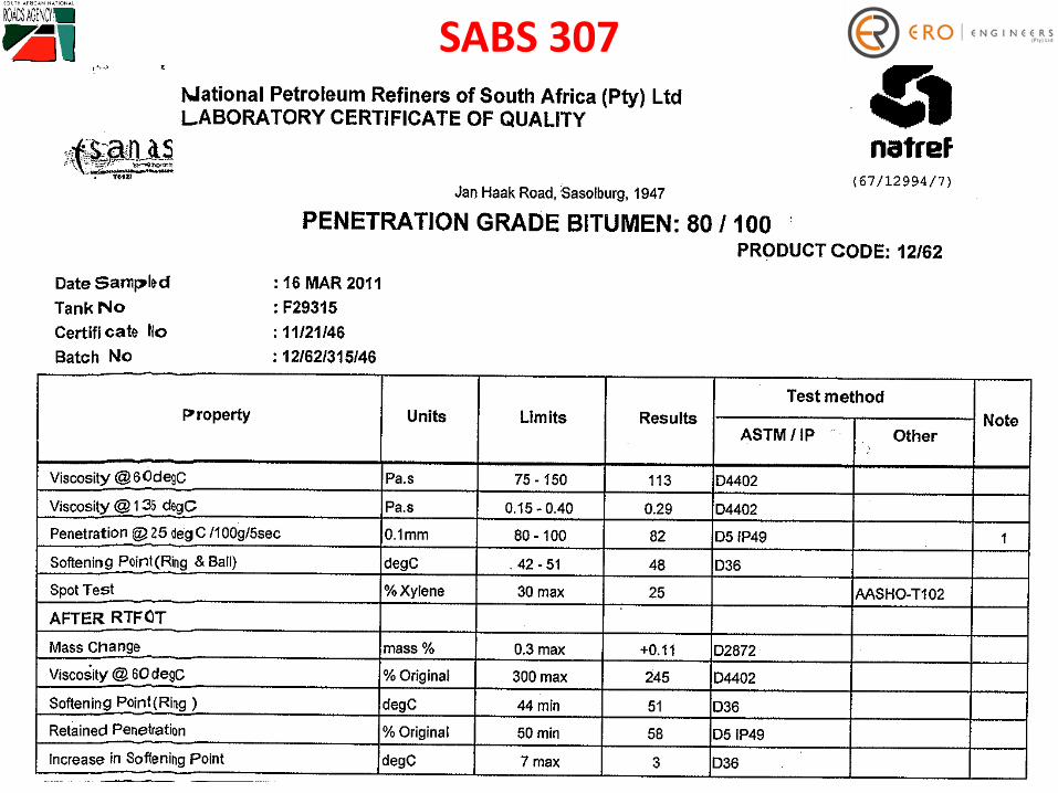
SABS 307
15

Compare different base bitumen – SABS 307
16

Bitumen blend
Check
•Viscosity
•Viscosity
•Viscosity• Temperature
• Softening Point
17

Taking samples after first spray application when spray bar is on temperature
18

Measuring Dynamic Viscosity
19

Typical results for a periodDynamic Viscosity (Haake @ 1900C) before spray
(green) and during spray (blue) for a period.V
IS
CO
SIT
Y (d
Pa
.s)
0
10
20
30
40
50
60
70
80
90
Max 40
Min 20
Number of days sprayed 20

Dynamic Viscosity curve for a specific batch
21

Non conformance - Dynamic Viscosity
22

Non conformance - Dynamic Viscosity
23

Specifications in TG 1, Project documentation and TRH 3 e.g. for Bitumen
rubber, SBR, SBS……etc.
24

Use different blends of base bitumen to achieve specifications
Base Bitumen Blend - 50:50, Natref:Calref
Base Bitumen Blend - 50:50, Natref:Calref
Base Bitumen Blend - 40:60, Natref:Calref
Base Bitumen Blend - 40:60, Natref:Calref
Base Bitumen Blend - 40:60, Natref:Calref
Base Bitumen Calref
Base Bitumen Blend - 40:60, Natref:Calref
Truck Broken Send Back
Base Bitumen Blend - 40:60, Natref:Calref
Base Bitumen Blend - 40:60, Natref:Calref
Base Bitumen Blend - 40:60, Natref:Calref
Base Bitumen Blend - 40:60, Natref:Calref
Base Bitumen Blend - 30:70 Natref:Calref
Base Bitumen Blend - 30:70 Natref:Calref
Base Bitumen Blend - 30:70, Natref:Calref
Check Samples Before Spray
25

Softening Point 0C
26Number of days sprayed
Soft
en
ing
Po
int
0C

Softening Point 0C
27

Remember: We want cheese cake with our bitumen
28

But: You cannot make cheese cake out of horse manure
29

Calibrate the temperature meter
30

To low temperature cause a poor application
31

Cold spray bar
32

Checklist – prior to seal
• Measure road width
33

Checklist – prior to seal
• Measure road width
• Mark applications or record
34

Checklist – prior to seal
• Measure road width
• Mark applications or record
• Set out parallel lanes
35

Checklist – prior to seal
• Measure road width
• Mark applications or record
• Set out parallel lanes
• Guardrails, bridge balustrades, access roads
36

Checklist – prior to seal
• Measure road width
• Mark applications or record
• Set out parallel lanes
• Constrains e.g. guardrails, bridge balustrades, access roads
• Traffic control
37

Checklist – prior to seal
• Measure road width
• Mark applications or record
• Set out parallel lanes
• Constrains e.g. guardrails, bridge balustrades, access roads
• Traffic control
• Calculate quantity bitumen needed for day
38

Checklist – During construction
• Discuss and agreewidthlength
39

Checklist – During construction
• Discuss and agreewidth length
• Method of joint construction
40

Checklist – During construction
• Discuss and agreewidth length
• Method of joint
• Longer section to avoid joints (300 -400m)
41

Checklist – During construction
• Discuss and agreewidth length
• Method of joint
• Longer section to avoid joints (300 -400m)
• Establish working procedure
42

Distributors varies - 6m wide spray bar
43

Make sure all parties are readyand informed
44
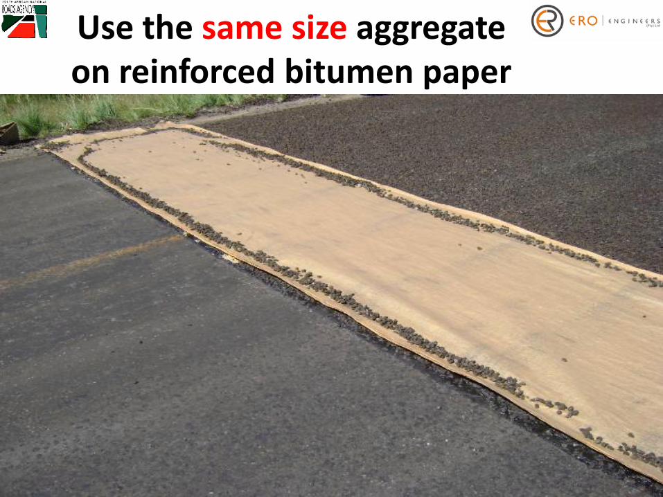
Use the same size aggregate on reinforced bitumen paper
45

Test spray bar / nozzles prior to spray
46

Apply an uniform tack coat without / with joints
47

Typical look of uniform applied rubber bitumen tack coat
48

Make sure of 1/3, 2/3 and fullapplication on joint – this will only
appear if viscosity is within specification
49

Demarcation string with first application of aggregate
50

Apply uniform layer of aggregate and take special care of joint
51

Apply uniform layer of aggregate
52

Keep the 1/3 and 2/3 application on joint free from aggregate
53

Keep 27t rollers as near as possible to chip operation (Hot binder only)
54

Roll, roll…………roll.
55

Use reinforced bitumen paper on all joints
56

Trim all joints
57

Construction of centre line joint
58

Typical look of centre line joint with binder application
59

Completed centre line jointDo not construct joints on top of each other
60

Always be present at the construction of the new seal
61

Must do before and after each spray
• Visually check for viscosity problems. Measure viscosity and record
62

Must do before and after each spray
• Visually check for viscosity problems. Measure viscosity and record
• Calculate binder application rate (l / m2)
63

Must do before and after each spray
• Visually check for viscosity problems. Measure viscosity and record
• Calculate binder application rate (l /m2)
• Calculate aggregate application rate (m2 / m3)
64

Must do before and after each spray
• Visually check for viscosity problems. Measure viscosity and record
• Calculate binder application rate (l/m2)
• Calculate aggregate application rate (m2 / m3)
• Take corrective action immediately if application rates and / or viscosity does not conform to the specifications or design
65
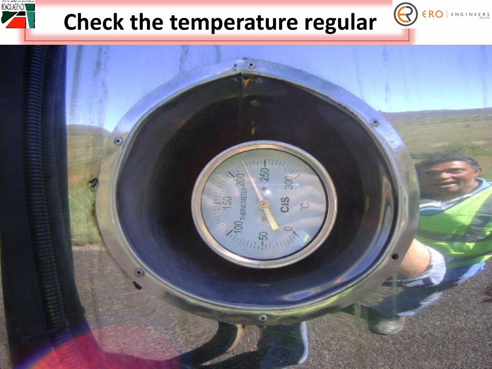
Check the temperature regular
66

TYPICAL DEFECTS
And Corrective action
67

Things shall go wrong
68

Corrective action
69

Non Conformance70

Corrective Action71

Trim corrective action work neatly
72

Protect completed work
73

Nozzles did not open
74

Chip spreader gate did not open
75

Distributor missed the centre line joint in curve
76

Spray areas without binder with single or double nozzle to correct the defect
77

The Engineer?
78

Avoid sharp turning on newly constructed seals
79

Fog spray
• Broom - remove all loose aggregate
80

Fog spray
• Broom - remove all loose aggregate
• Roll with light steel drum roller (5 – 8 ton) after back chipping
81

Fog spray
• Broom - remove all loose aggregate
• Roll with light steel drum roller (5 – 8 ton) after back chipping
• Apply fog spray
- Up to 0.8 l/m2 Cat 33% or Cat 35%
82

Fog spray
• Broom - remove all loose aggregate
• Roll with light steel drum roller (5 – 8 ton) after back chipping
• Apply fog spray
- Up to 0.8 l/m2 Cat 33% or Cat 35%
- 0.8 – 1,2 l/m2 Cat 45%
83

Fog spray
• Broom - remove all loose aggregate
• Roll with light steel drum roller (5 – 8 ton) after back chipping
• Apply fog spray
- Up to 0.8 l/m2 Cat 33% or Cat 35%
- 0.8 – 1,2 l/m2 Cat 45%
• Open to traffic 24 - 48 hours later
84

After care
• Second application of fog spray
85

After care
• Second application of fog spray
• Free from all loose aggregate
86

After care
• Second application of fog spray
• Free from all loose aggregate
• Newly constructed seals need traffic
87

Construction of seals
Consultants perspective
Thanks
ERO Engineers (Pty) Ltd
Freddie Henning88