Salem License Renewal Application
1753
LICENSE RENEWAL APPLICATION Salem Nuclear Generating Station Unit 1 Facility Operating License No. DPR-70 Unit 2 Facility Operating License No. DPR-75
Transcript of Salem License Renewal Application

LICENSE RENEWAL APPLICATION
Salem Nuclear Generating Station
Unit 1 Facility Operating License No. DPR-70
Unit 2 Facility Operating License No. DPR-75
Table of Contents
Salem Nuclear Generating Station, Unit No. 1 and Unit No. 2 Page i License Renewal Application
TABLE OF CONTENTS
SECTION 1
ADMINISTRATIVE INFORMATION
1.0 ADMINISTRATIVE INFORMATION........................................................1-1
1.1 GENERAL INFORMATION – 10 CFR 54.19 ..........................................1-1 1.1.1 Name of Applicant...................................................................................1-1 1.1.2 Address of Applicant ...............................................................................1-1 1.1.3 Descriptions of Business or Occupation of Applicant..............................1-1 1.1.4 Descriptions of Organization and Management of Applicant ..................1-1 1.1.5 Class of License, Use of the Facility, and Period of Time for Which
the License is Sought .............................................................................1-2 1.1.6 Earliest and Latest Dates for Alterations, If Proposed ............................1-3 1.1.7 Restricted Data .......................................................................................1-3 1.1.8 Regulatory Agencies ...............................................................................1-3 1.1.9 Local News Publications .........................................................................1-3 1.1.10 Conforming Changes To Standard Indemnity Agreement ......................1-4
1.2 GENERAL LICENSE INFORMATION ....................................................1-5 1.2.1 Application Updates, Renewed Licenses, and Renewal Term
Operation................................................................................................1-5 1.2.2 Contact Information.................................................................................1-5
1.3 PURPOSE ..............................................................................................1-6
1.4 DESCRIPTION OF THE PLANT.............................................................1-6
1.5 APPLICATION STRUCTURE .................................................................1-7
1.6 ACRONYMS .........................................................................................1-10
1.7 GENERAL REFERENCES ...................................................................1-13
Table of Contents
Salem Nuclear Generating Station, Unit No. 1 and Unit No. 2 Page ii License Renewal Application
SECTION 2
SCOPING AND SCREENING METHODOLOGY FOR IDENTIFYING STRUCTURES AND COMPONENTS SUBJECT TO AGING
MANAGEMENT REVIEW, AND IMPLEMENTATION RESULTS 2.0 SCOPING AND SCREENING METHODOLOGY FOR IDENTIFYING
STRUCTURES AND COMPONENTS SUBJECT TO AGING MANAGEMENT REVIEW, AND IMPLEMENTATION RESULTS...............2.0-1
2.1 SCOPING AND SCREENING METHODOLOGY .......................................2.1-1 2.1.1 Introduction..........................................................................................2.1-1 2.1.2 Information Sources Used for Scoping and Screening........................2.1-4 2.1.3 Technical Basis Documents ................................................................2.1-5 2.1.4 Interim Staff Guidance Discussion ....................................................2.1-14 2.1.5 Scoping Procedure ............................................................................2.1-16 2.1.6 Screening Procedure.........................................................................2.1-24 2.1.7 Generic Safety Issues .......................................................................2.1-32 2.1.8 Conclusion.........................................................................................2.1-33 2.2 PLANT LEVEL SCOPING RESULTS.........................................................2.2-1 2.3 SCOPING AND SCREENING RESULTS: MECHANICAL ........................2.3-1 2.3.1 Reactor Vessel, Internals, and Reactor Coolant System ....................2.3-1 2.3.1.1 Reactor Coolant System.............................................................2.3-2 2.3.1.2 Reactor Vessel .........................................................................2.3-11 2.3.1.3 Reactor Vessel Internals...........................................................2.3-17 2.3.1.4 Steam Generators ....................................................................2.3-26 2.3.2 Engineered Safety Features..............................................................2.3-33 2.3.2.1 Containment Spray System......................................................2.3-34 2.3.2.2 Residual Heat Removal System ...............................................2.3-39 2.3.2.3 Safety Injection System ............................................................2.3-47 2.3.3 Auxiliary Systems ..............................................................................2.3-55 2.3.3.1 Auxiliary Building Ventilation System........................................2.3-56 2.3.3.2 Chemical & Volume Control System.........................................2.3-62 2.3.3.3 Chilled Water System ...............................................................2.3-73 2.3.3.4 Circulating Water System .........................................................2.3-80 2.3.3.5 Component Cooling System.....................................................2.3-85 2.3.3.6 Compressed Air System ...........................................................2.3-92 2.3.3.7 Containment Ventilation System...............................................2.3-98 2.3.3.8 Control Area Ventilation System.............................................2.3-106 2.3.3.9 Cranes and Hoists ..................................................................2.3-113
Table of Contents
Salem Nuclear Generating Station, Unit No. 1 and Unit No. 2 Page iii License Renewal Application
2.3.3.10 Demineralized Water System .................................................2.3-117 2.3.3.11 Emergency Diesel Generator & Auxiliaries System................2.3-124 2.3.3.12 Fire Protection System ...........................................................2.3-130 2.3.3.13 Fresh Water System ...............................................................2.3-137 2.3.3.14 Fuel Handling & Fuel Storage System....................................2.3-141 2.3.3.15 Fuel Handling Ventilation System...........................................2.3-146 2.3.3.16 Fuel Oil System ......................................................................2.3-150 2.3.3.17 Heating Water and Heating Steam System ............................2.3-155 2.3.3.18 Non-radioactive Drain System................................................2.3-160 2.3.3.19 Radiation Monitoring System..................................................2.3-165 2.3.3.20 Radioactive Drain System ......................................................2.3-172 2.3.3.21 Radwaste System...................................................................2.3-179 2.3.3.22 Sampling System....................................................................2.3-188 2.3.3.23 Service Water System ............................................................2.3-194 2.3.3.24 Service Water Ventilation System ..........................................2.3-202 2.3.3.25 Spent Fuel Cooling System ....................................................2.3-206 2.3.3.26 Switchgear and Penetration Area Ventilation System ............2.3-211 2.3.4 Steam and Power Conversion System............................................2.3-215 2.3.4.1 Auxiliary Feedwater System ...................................................2.3-216 2.3.4.2 Main Condensate and Feedwater System..............................2.3-222 2.3.4.3 Main Condenser and Air Removal System.............................2.3-227 2.3.4.4 Main Steam System................................................................2.3-231 2.3.4.5 Main Turbine and Auxiliaries System .....................................2.3-237 2.4 SCOPING AND SCREENING RESULTS: CONTAINMENT,
STRUCTURES AND COMPONENT SUPPORTS ...................................... 2.4-1 2.4.1 Auxiliary Building ........................................................................2.4-2 2.4.2 Component Supports Commodity Group....................................2.4-9 2.4.3 Containment Structure..............................................................2.4-14 2.4.4 Fire Pump House......................................................................2.4-23 2.4.5 Fuel Handling Building..............................................................2.4-27 2.4.6 Office Buildings.........................................................................2.4-33 2.4.7 Penetration Areas .....................................................................2.4-39 2.4.8 Pipe Tunnel...............................................................................2.4-43 2.4.9 Piping and Component Insulation Commodity Group...............2.4-46 2.4.10 SBO Compressor Building........................................................2.4-49 2.4.11 Service Building ........................................................................2.4-52 2.4.12 Service Water Accumulator Enclosures ...................................2.4-57 2.4.13 Service Water Intake ................................................................2.4-60 2.4.14 Shoreline Protection and Dike ..................................................2.4-65 2.4.15 Switchyard ................................................................................2.4-68 2.4.16 Turbine Building........................................................................2.4-71 2.4.17 Yard Structures.........................................................................2.4-75

Table of Contents
Salem Nuclear Generating Station, Unit No. 1 and Unit No. 2 Page iv License Renewal Application
2.5 SCOPING AND SCREENING RESULTS: ELECTRICAL AND INSTRUMENTATION AND CONTROLS (I&C) SYSTEMS .......................... 2.5-1
2.5.1 Electrical/I&C Component Commodity Groups ...................................2.5-1 2.5.2 Electrical Component Commodity Groups ..........................................2.5-3 2.5.2.1 Identification of Electrical Component Commodity Groups ........2.5-3 2.5.2.2 Application of Screening Criterion 10 CFR 54.21(a)(1)(i) to
the Electrical Component Commodity Groups............................2.5-4 2.5.2.3 Elimination of Electrical Component Commodity Groups
With No License Renewal Intended Functions ..........................2.5-4 2.5.2.4 Application of Screening Criterion 10 CFR 54.21(a)(1)(ii) to
Electrical Component Commodity Groups..................................2.5-5 2.5.2.5 Electrical Component Commodity Groups Subject to Aging
Management Review ..................................................................2.5-6 2.5.2.5.1 Cable Connections-Metallic Parts ..............................................2.5-6 2.5.2.5.2 Connector Contacts for Electrical Connectors Exposed to
Borated Water Leakage .............................................................2.5-6 2.5.2.5.3 Electrical Penetrations ...............................................................2.5-6 2.5.2.5.4 Fuse Holders ..............................................................................2.5-6 2.5.2.5.5 High Voltage Insulators ..............................................................2.5-6 2.5.2.5.6 Insulated Cables and Connections .............................................2.5-7 2.5.2.5.7 Metal Enclosed Bus ....................................................................2.5-7 2.5.2.5.8 Switchyard Bus and Connections ...............................................2.5-7

Table of Contents
Salem Nuclear Generating Station, Unit No. 1 and Unit No. 2 Page v License Renewal Application
SECTION 3
AGING MANAGEMENT REVIEW RESULTS 3.0 AGING MANAGEMENT REVIEW RESULTS.............................................3.0-1 3.1 AGING MANAGEMENT OF REACTOR VESSEL, INTERNALS AND
REACTOR COOLANT SYSTEM ................................................................3.1-1 3.1.1 Introduction ..........................................................................................3.1-1 3.1.2 Results .................................................................................................3.1-1 3.1.2.1 Materials, Environments, Aging Effects Requiring Management and Aging Management Programs......................................................3.1-1 3.1.2.2 AMR Results for Which Further Evaluation is Recommended by the GALL Report.............................................................................3.1-7 3.1.2.3 Time-Limited Aging Analyses ............................................................3.1-16 3.1.3 Conclusion.........................................................................................3.1-16 3.2 AGING MANAGEMENT OF ENGINEERED SAFETY FEATURES............3.2-1 3.2.1 Introduction ..........................................................................................3.2-1 3.2.2 Results .................................................................................................3.2-1 3.2.2.1 Materials, Environments, Aging Effects Requiring Management and Aging Management Programs......................................................3.2-1 3.2.2.2 AMR Results for Which Further Evaluation is Recommended by the GALL Report.............................................................................3.2-5 3.2.2.3 Time-Limited Aging Analyses ............................................................3.2-11 3.2.3 Conclusion.........................................................................................3.2-11 3.3 AGING MANAGEMENT OF AUXILIARY SYSTEMS..................................3.3-1 3.3.1 Introduction ..........................................................................................3.3-1 3.3.2 Results .................................................................................................3.3-2 3.3.2.1 Materials, Environments, Aging Effects Requiring Management and Aging Management Programs......................................................3.3-3 3.3.2.2 AMR Results for Which Further Evaluation is Recommended by the GALL Report...........................................................................3.3-36 3.3.2.3 Time-Limited Aging Analyses ............................................................3.3-52

Table of Contents
Salem Nuclear Generating Station, Unit No. 1 and Unit No. 2 Page vi License Renewal Application
3.3.3 Conclusion.........................................................................................3.3-52 3.4 AGING MANAGEMENT OF STEAM AND POWER CONVERSION
SYSTEM ....................................................................................................3.4-1 3.4.1 Introduction ..........................................................................................3.4-1 3.4.2 Results .................................................................................................3.4-1 3.4.2.1 Materials, Environments, Aging Effects Requiring Management and Aging Management Programs......................................................3.4-2 3.4.2.2 AMR Results for Which Further Evaluation is Recommended by the GALL Report.............................................................................3.4-8 3.4.2.3 Time-Limited Aging Analyses ............................................................3.4-15 3.4.3 Conclusion.........................................................................................3.4-15 3.5 AGING MANAGEMENT OF CONTAINMENTS, STRUCTURES, AND
COMPONENT SUPPORTS........................................................................3.5-1 3.5.1 Introduction ..........................................................................................3.5-1 3.5.2 Results .................................................................................................3.5-1 3.5.2.1 Materials, Environments, Aging Effects Requiring Management and Aging Management Programs......................................................3.5-2 3.5.2.2 AMR Results for Which Further Evaluation is Recommended by the GALL Report...........................................................................3.5-26 3.5.2.3 Time-Limited Aging Analyses ............................................................3.5-54 3.5.3 Conclusion.........................................................................................3.5-54 3.6 AGING MANAGEMENT OF ELECTRICAL AND INSTRUMENTATION AND CONTROLS................................................................................................3.6-1 3.6.1 Introduction ..........................................................................................3.6-1 3.6.2 Results .................................................................................................3.6-1 3.6.2.1 Materials, Environments, Aging Effects Requiring Management and Aging Management Programs......................................................3.6-1 3.6.2.2 AMR Results for Which Further Evaluation is Recommended by the GALL Report.............................................................................3.6-6 3.6.2.3 AMR Results Not Consistent with or Not Addressed in the GALL
Report................................................................................................3.6-10 3.6.3 Conclusion.........................................................................................3.6-11

Table of Contents
Salem Nuclear Generating Station, Unit No. 1 and Unit No. 2 Page vii License Renewal Application
SECTION 4
TIME-LIMITED AGING ANALYSES 4.0 TIME-LIMITED AGING ANALYSES.............................................................4-1 4.1 INTRODUCTION..........................................................................................4-1 4.1.1 Identification of TLAAs ............................................................................4-1 4.1.2 Identification of Exemptions ....................................................................4-3 4.1.3 Summary of Results................................................................................4-3 4.2 REACTOR VESSEL NEUTRON EMBRITTLEMENT...................................4-6 4.2.1 Neutron Fluence Analyses ......................................................................4-7 4.2.2 Upper Shelf Energy Analyses ...............................................................4-10 4.2.3 Pressurized Thermal Shock Analyses ..................................................4-14 4.2.4 Reactor Vessel Pressure-Temperature Limits, Including Low
Temperature Overpressurization Protection Limits...............................4-19 4.3 METAL FATIGUE OF PIPING AND COMPONENTS ................................4-22 4.3.1 Nuclear Steam Supply System (NSSS) Pressure Vessel and
Component Fatigue Analyses ..............................................................4-23 4.3.2 Pressurizer Safety Valve and Pilot-Operated Relief Valve Fatigue
Analyses ...............................................................................................4-32 4.3.3 ASA/USAS B31.1 Piping Fatigue Analyses…………............................4-34 4.3.4 Supplementary ASME Section III, Class 1 Piping and Component
Fatigue Analyses ..................................................................................4-35 4.3.5 Reactor Vessel Internals Fatigue Analyses ..........................................4-40 4.3.6 Spent Fuel Pool Bottom Plates Fatigue Analyses.................................4-40 4.3.7 Environmentally-Assisted Fatigue Analyses .........................................4-42 4.4 OTHER PLANT-SPECFIC ANALYSES......................................................4-46 4.4.1 Reactor Vessel Underclad Cracking Analyses......................................4-46 4.4.2 Reactor Coolant Pump Flywheel Fatigue Crack Growth Analysis ........4-48 4.4.3 Leak-Before-Break Analyses ...............................................................4-49 4.4.4 Applicability of ASME Code Case N-481 to the Salem Units 1 and
2 Reactor Coolant Pump Casings.........................................................4-50 4.4.5 Salem Unit 1 Volume Control Tank Flaw Growth Analysis ..................4-51 4.5 FUEL TRANSFER TUBE BELLOWS DESIGN CYCLES...........................4-52 4.6 CRANE LOAD CYCLE LIMITS...................................................................4-53 4.6.1 Polar Gantry Crane ..............................................................................4-53 4.6.2 Fuel Handling Crane .............................................................................4-53 4.6.3 Cask Handling Crane ............................................................................4-54

Table of Contents
Salem Nuclear Generating Station, Unit No. 1 and Unit No. 2 Page viii License Renewal Application
4.7 ENVIRONMENTAL QUALIFICATION OF ELECTRIC EQUIPMENT ........4-55 4.8 REFERENCES ..........................................................................................4-58 List of Appendices APPENDIX A – FINAL SAFETY ANALYSIS REPORT SUPPLEMENT APPENDIX B – AGING MANAGEMENT PROGRAMS APPENDIX C – NOT USED APPENDIX D – TECHNICAL SPECIFICATION CHANGES APPENDIX E – ENVIRONMENTAL REPORT FOR SALEM NUCLEAR
GENERATING STATION UNITS 1 AND 2

Table of Contents
Salem Nuclear Generating Station, Unit No. 1 and Unit No. 2 Page ix License Renewal Application
List of Tables
Table 2.1-1 Passive Structure and Component Intended Function Definitions .......2.1-29 Table 2.2-1 Plant Level Scoping Results...................................................................2.2-2 Table 2.3.1-1 Components Subject to Aging Management Review -
Reactor Coolant System...................................................................2.3-9
Table 2.3.1-2 Components Subject to Aging Management Review - Reactor Vessel ...............................................................................2.3-15
Table 2.3.1-3 Components Subject to Aging Management Review - Reactor Vessel Internals ..............................................................................2.3-21
Table 2.3.1-4 Components Subject to Aging Management Review - Steam Generators......................................................................................2.3-31
Table 2.3.2-1 Components Subject to Aging Management Review - Containment Spray System............................................................2.3-38
Table 2.3.2-2 Components Subject to Aging Management Review - Residual Heat Removal System....................................................................2.3-46
Table 2.3.2-3 Components Subject to Aging Management Review - Safety Injection System .............................................................................2.3-53
Table 2.3.3-1 Components Subject to Aging Management Review - Auxiliary Building Ventilation System ............................................................2.3-61
Table 2.3.3-2 Components Subject to Aging Management Review - Chemical & Volume Control System ..............................................................2.3-70
Table 2.3.3-3 Components Subject to Aging Management Review - Chilled Water System .................................................................................2.3-78
Table 2.3.3-4 Components Subject to Aging Management Review - Circulating Water System .................................................................................2.3-84
Table 2.3.3-5 Components Subject to Aging Management Review - Component Cooling System...........................................................2.3-89
Table 2.3.3-6 Components Subject to Aging Management Review - Compressed Air System.................................................................2.3-96
Table 2.3.3-7 Components Subject to Aging Management Review - Containment Ventilation System ..................................................2.3-105
Table 2.3.3-8 Components Subject to Aging Management Review - Control Area Ventilation System ...............................................................2.3-112
Table 2.3.3-9 Components Subject to Aging Management Review - Cranes and Hoists.....................................................................................2.3-116
Table 2.3.3-10 Components Subject to Aging Management Review - Demineralized Water System .......................................................2.3-123
Table 2.3.3-11 Components Subject to Aging Management Review - Emergency Diesel Generator & Auxiliaries System......................2.3-128

Table of Contents
Salem Nuclear Generating Station, Unit No. 1 and Unit No. 2 Page x License Renewal Application
Table 2.3.3-12 Components Subject to Aging Management Review - Fire Protection System ........................................................................2.3-135
Table 2.3.3-13 Components Subject to Aging Management Review - Fresh Water System ...............................................................................2.3-140
Table 2.3.3-14 Components Subject to Aging Management Review - Fuel Handling & Fuel Storage System .................................................2.3-145
Table 2.3.3-15 Components Subject to Aging Management Review - Fuel Handling Ventilation System.........................................................2.3-149
Table 2.3.3-16 Components Subject to Aging Management Review - Fuel Oil System..........................................................................................2.3-154
Table 2.3.3-17 Components Subject to Aging Management Review - Heating Water and Heating Steam System ...............................................2.3-158
Table 2.3.3-18 Components Subject to Aging Management Review - Non-radioactive Drain System..............................................................2.3-164
Table 2.3.3-19 Components Subject to Aging Management Review - Radiation Monitoring System........................................................................2.3-171
Table 2.3.3-20 Components Subject to Aging Management Review - Radioactive Drain System ............................................................2.3-178
Table 2.3.3-21 Components Subject to Aging Management Review - Radwaste System..........................................................................................2.3-185
Table 2.3.3-22 Components Subject to Aging Management Review - Sampling System..........................................................................................2.3-193
Table 2.3.3-23 Components Subject to Aging Management Review - Service Water System ...............................................................................2.3-199
Table 2.3.3-24 Components Subject to Aging Management Review - Service Water Ventilation System .............................................................2.3-205
Table 2.3.3-25 Components Subject to Aging Management Review - Spent Fuel Cooling System ............................................................................2.3-210
Table 2.3.3-26 Components Subject to Aging Management Review - Switchgear and Penetration Area Ventilation System ..................2.3-214
Table 2.3.4-1 Components Subject to Aging Management Review - Auxiliary
Feedwater System........................................................................2.3-220 Table 2.3.4-2 Components Subject to Aging Management Review - Main
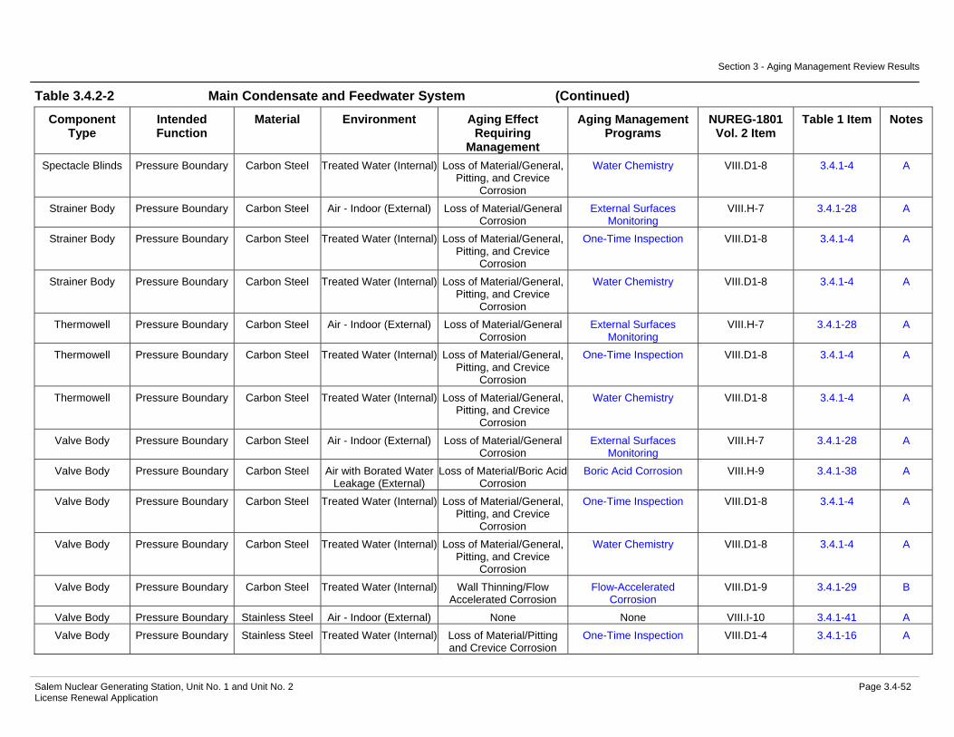
Condensate and Feedwater System ............................................2.3-226 Table 2.3.4-3 Components Subject to Aging Management Review - Main
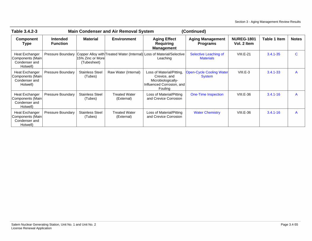
Condenser and Air Removal System ...........................................2.3-230 Table 2.3.4-4 Components Subject to Aging Management Review - Main
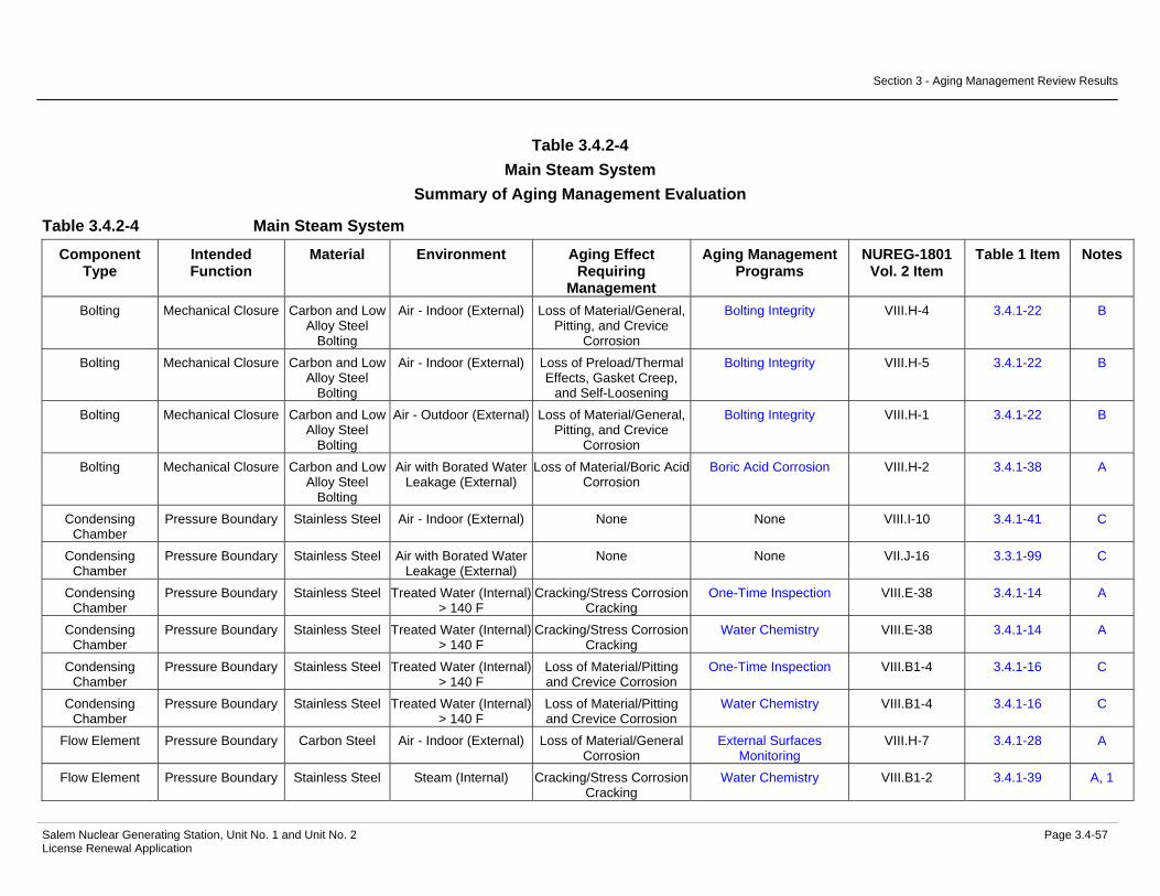
Steam System ..............................................................................2.3-236 Table 2.3.4-5 Components Subject to Aging Management Review - Main
Turbine and Auxiliaries System ....................................................2.3-241 Table 2.4-1 Components Subject to Aging Management Review – Auxiliary
Building...................................................................................................2.4-6

Table of Contents
Salem Nuclear Generating Station, Unit No. 1 and Unit No. 2 Page xi License Renewal Application
Table 2.4-2 Components Subject to Aging Management Review - Component Supports Commodity Group .................................................................2.4-11
Table 2.4-3 Components Subject to Aging Management Review - Containment Structure ...............................................................................................2.4-20
Table 2.4-4 Components Subject to Aging Management Review - Fire Pump House ...................................................................................................2.4-25
Table 2.4-5 Components Subject to Aging Management Review - Fuel Handling Building.................................................................................................2.4-30
Table 2.4-6 Components Subject to Aging Management Review - Office Buildings...............................................................................................2.4-37
Table 2.4-7 Components Subject to Aging Management Review - Penetration Areas ....................................................................................................2.4-41
Table 2.4-8 Components Subject to Aging Management Review - Pipe Tunnel.....2.4-45 Table 2.4-9 Components Subject to Aging Management Review - Piping and
Component Insulation Commodity Group ............................................2.4-48 Table 2.4-10 Components Subject to Aging Management Review - SBO
Compressor Building ............................................................................2.4-51 Table 2.4-11 Components Subject to Aging Management Review - Service
Building.................................................................................................2.4-55 Table 2.4-12 Components Subject to Aging Management Review - Service Water
Accumulator Enclosures.......................................................................2.4-59 Table 2.4-13 Components Subject to Aging Management Review - Service Water
Intake....................................................................................................2.4-63 Table 2.4-14 Components Subject to Aging Management Review - Shoreline
Protection and Dike ..............................................................................2.4-67 Table 2.4-15 Components Subject to Aging Management Review - Switchyard ......2.4-70 Table 2.4-16 Components Subject to Aging Management Review - Turbine
Building.................................................................................................2.4-73 Table 2.4-17 Components Subject to Aging Management Review - Yard
Structures .............................................................................................2.4-81 Table 2.5.2-1 Electrical Component Commodity Groups Subject to Aging
Management Review........................................................................2.5-8 Table 3.0-1 Salem Internal Service Environments ....................................................3.0-6 Table 3.0-2 Salem External Service Environments ...................................................3.0-9 Table 3.1.1 Summary of Aging Management Evaluations for the Reactor Vessel,
Internals, and Reactor Coolant System................................................3.1-18 Table 3.1.2-1 Reactor Coolant System Summary of Aging Management
Evaluation.......................................................................................3.1-46 Table 3.1.2-2 Reactor Vessel Summary of Aging Management Evaluation .........3.1-67

Table of Contents
Salem Nuclear Generating Station, Unit No. 1 and Unit No. 2 Page xii License Renewal Application
Table 3.1.2-3 Reactor Vessel Internals System Summary of Aging Management Evaluation.................................................................3.1-80
Table 3.1.2-4 Steam Generators Summary of Aging Management Evaluation ..3.1-129 Table 3.2.1 Summary of Aging Management Evaluations for the Engineered
Safety Features ....................................................................................3.2-12 Table 3.2.2-1 Containment Spray System Summary of Aging Management
Evaluation.......................................................................................3.2-33 Table 3.2.2-2 Residual Heat Removal System Summary of Aging
Management Evaluation.................................................................3.2-37 Table 3.2.2-3 Safety Injection System Summary of Aging Management
Evaluation.......................................................................................3.2-42 Table 3.3.1 Summary of Aging Management Evaluations for the Auxiliary
Systems................................................................................................3.3-53 Table 3.3.2-1 Auxiliary Building Ventilation System Summary of Aging
Management Evaluation...............................................................3.3-118 Table 3.3.2-2 Chemical & Volume Control System Summary of Aging
Management Evaluation...............................................................3.3-124 Table 3.3.2-3 Chilled Water System Summary of Aging Management
Evaluation.....................................................................................3.3-142 Table 3.3.2-4 Circulating Water System Summary of Aging Management
Evaluation.....................................................................................3.3-156 Table 3.3.2-5 Component Cooling System Summary of Aging Management
Evaluation.....................................................................................3.3-159 Table 3.3.2-6 Compressed Air System Summary of Aging Management
Evaluation.....................................................................................3.3-184 Table 3.3.2-7 Containment Ventilation System Summary of Aging
Management Evaluation...............................................................3.3-197 Table 3.3.2-8 Control Area Ventilation System Summary of Aging
Management Evaluation...............................................................3.3-202 Table 3.3.2-9 Cranes and Hoists Summary of Aging Management Evaluation..3.3-206 Table 3.3.2-10 Demineralized Water System Summary of Aging Management
Evaluation.....................................................................................3.3-210 Table 3.3.2-11 Emergency Diesel Generator & Auxiliaries System Summary of
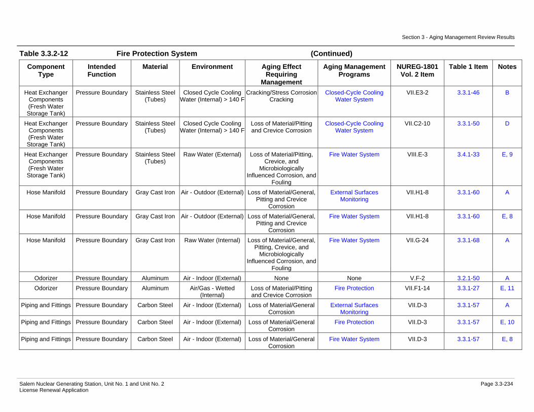
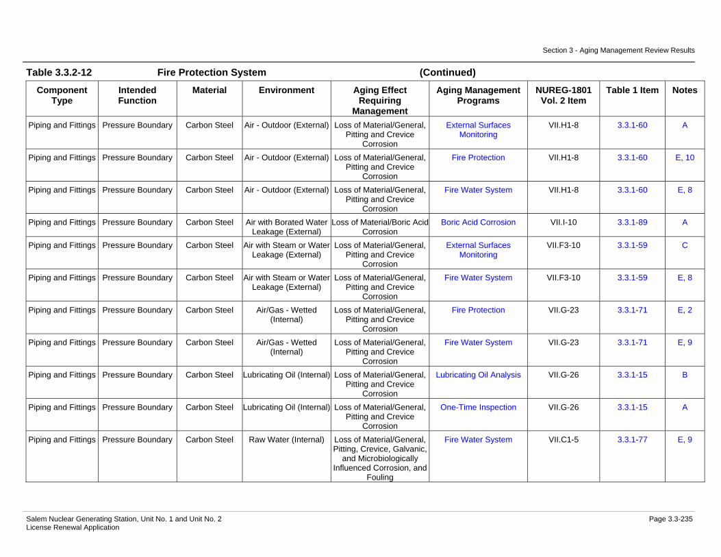
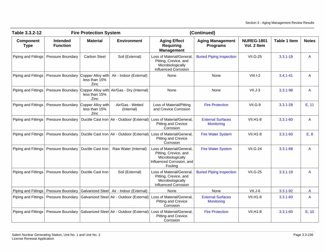
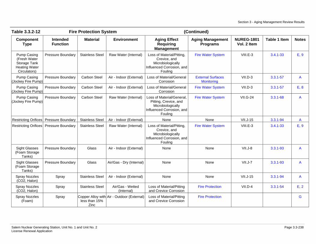
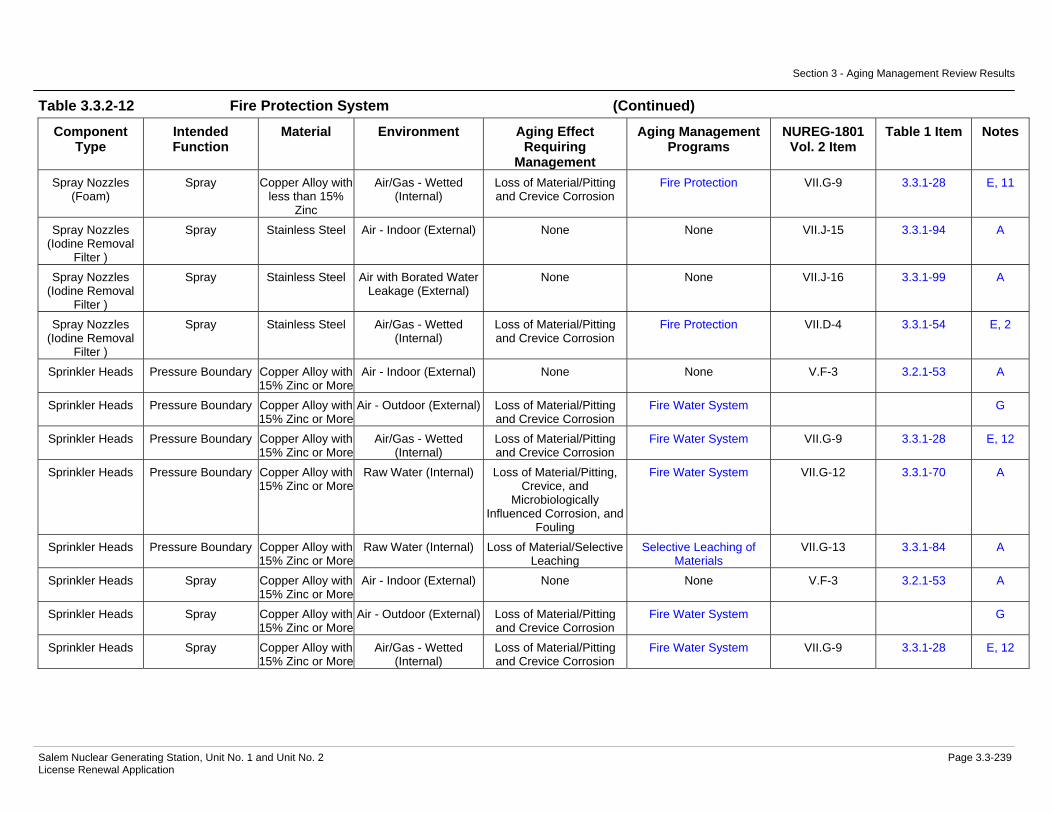
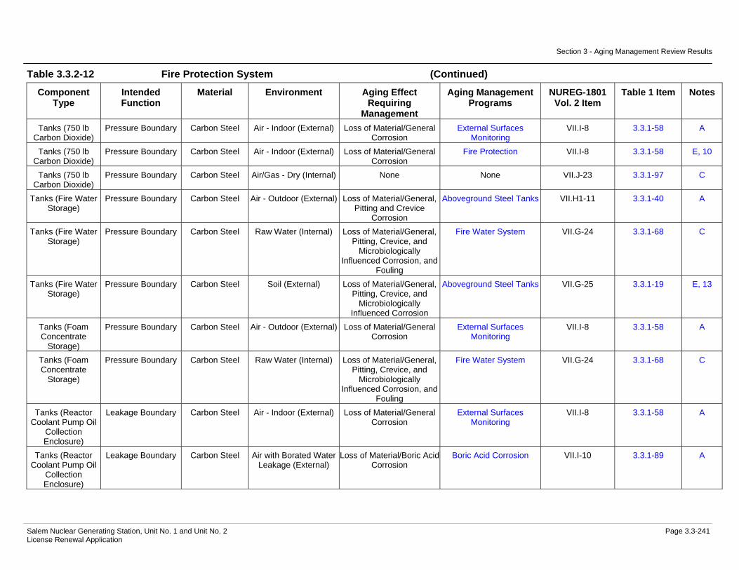
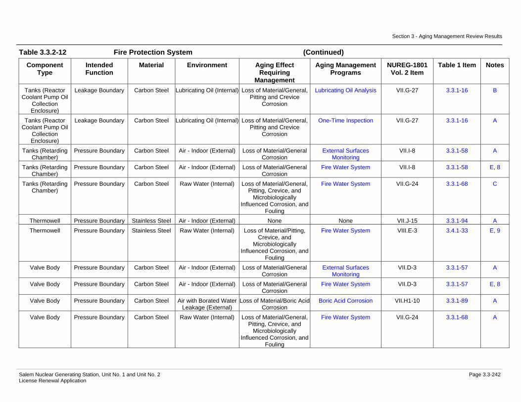
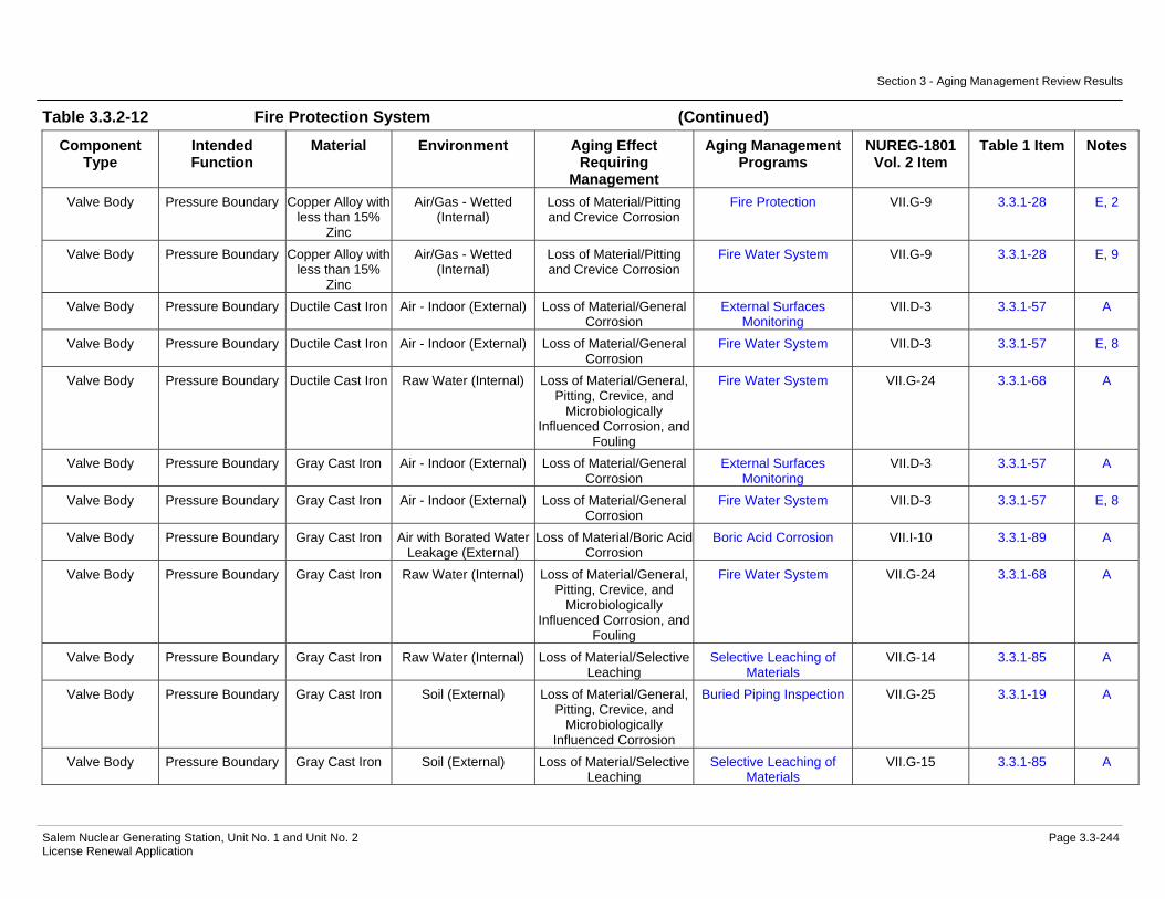
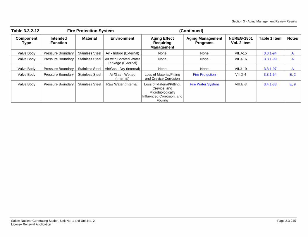
Aging Management Evaluation.....................................................3.3-217 Table 3.3.2-12 Fire Protection System Summary of Aging Management
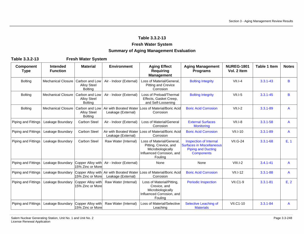
Evaluation.....................................................................................3.3-226 Table 3.3.2-13 Fresh Water System Summary of Aging Management
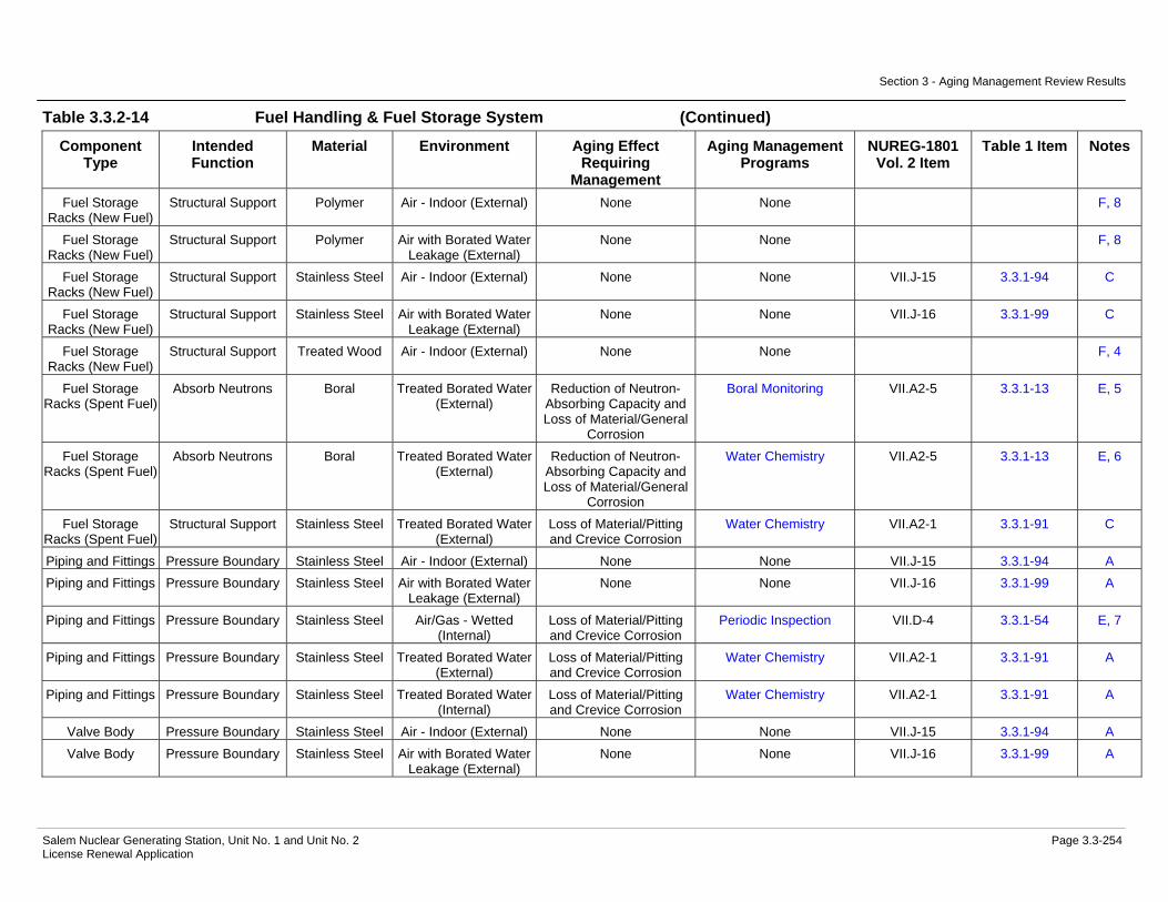
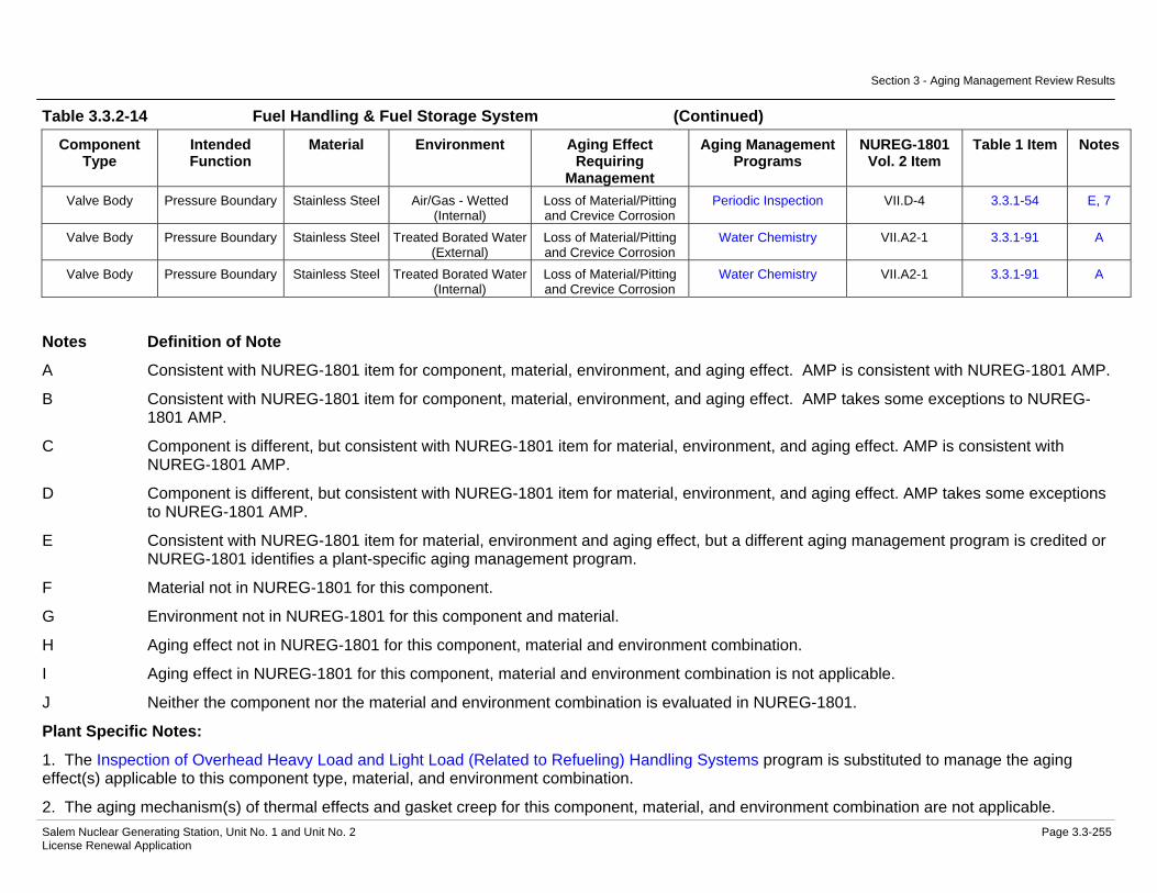
Evaluation.....................................................................................3.3-248 Table 3.3.2-14 Fuel Handling & Fuel Storage System Summary of Aging
Management Evaluation...............................................................3.3-251

Table of Contents
Salem Nuclear Generating Station, Unit No. 1 and Unit No. 2 Page xiii License Renewal Application
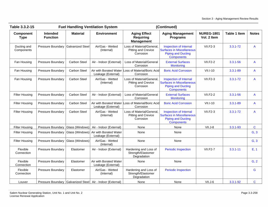
Table 3.3.2-15 Fuel Handling Ventilation System Summary of Aging Management Evaluation...............................................................3.3-257
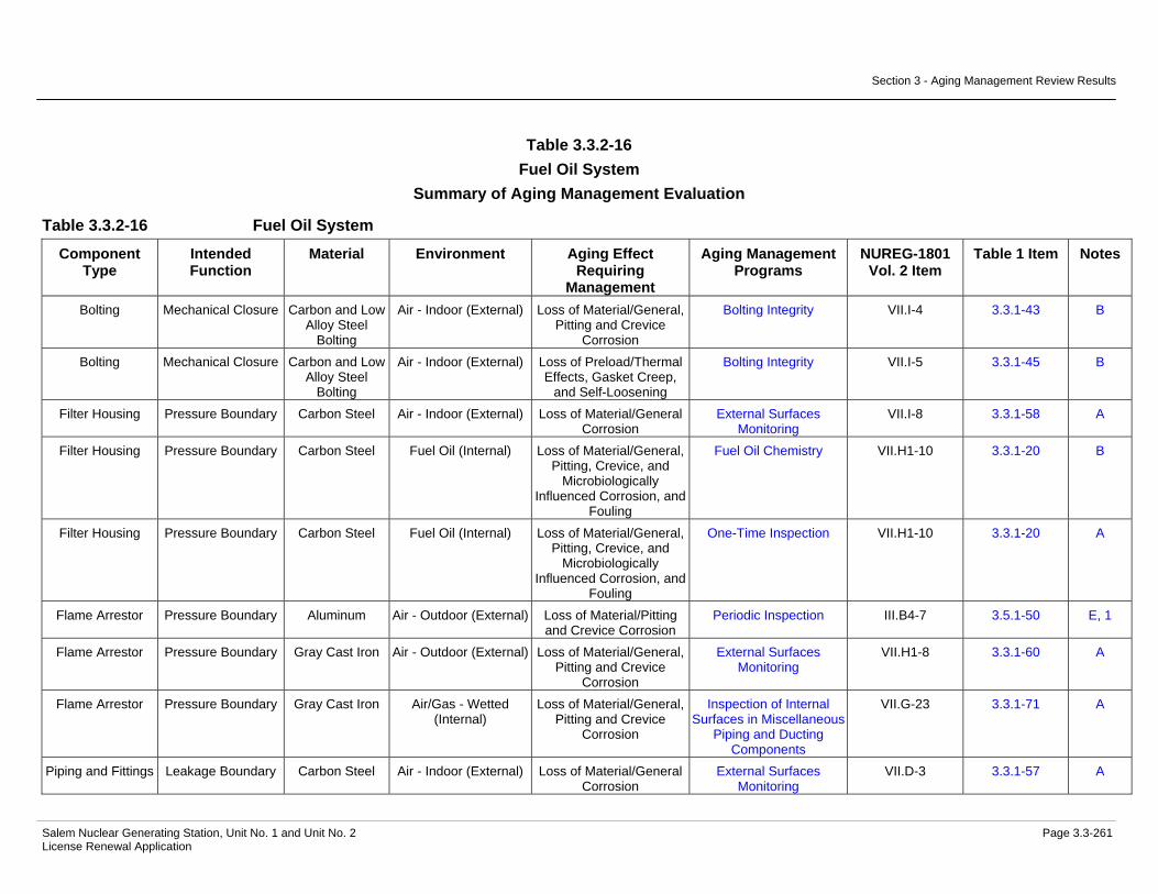
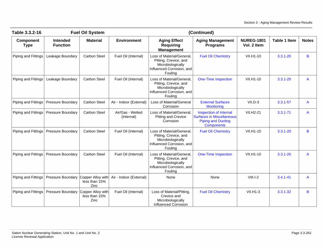
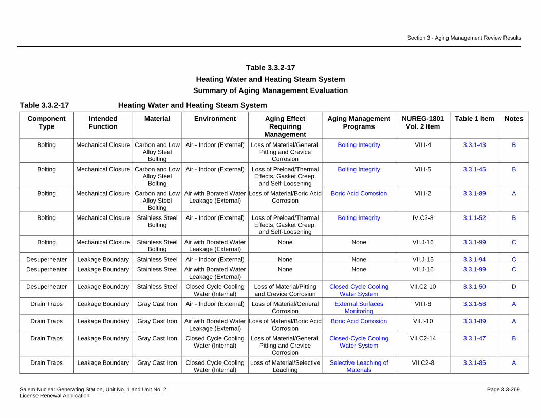
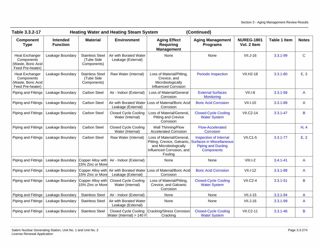
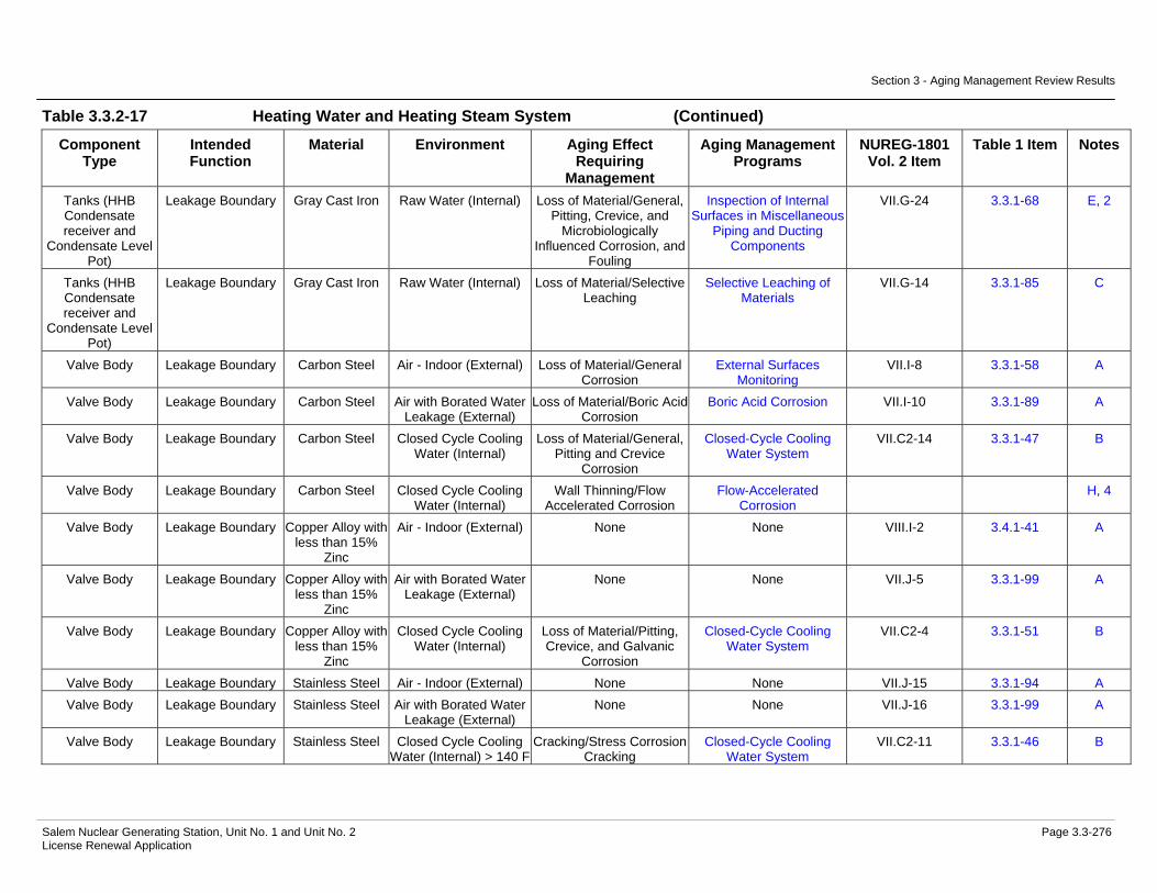
Table 3.3.2-16 Fuel Oil System Summary of Aging Management Evaluation ......3.3-261 Table 3.3.2-17 Heating Water and Heating Steam System Summary of Aging
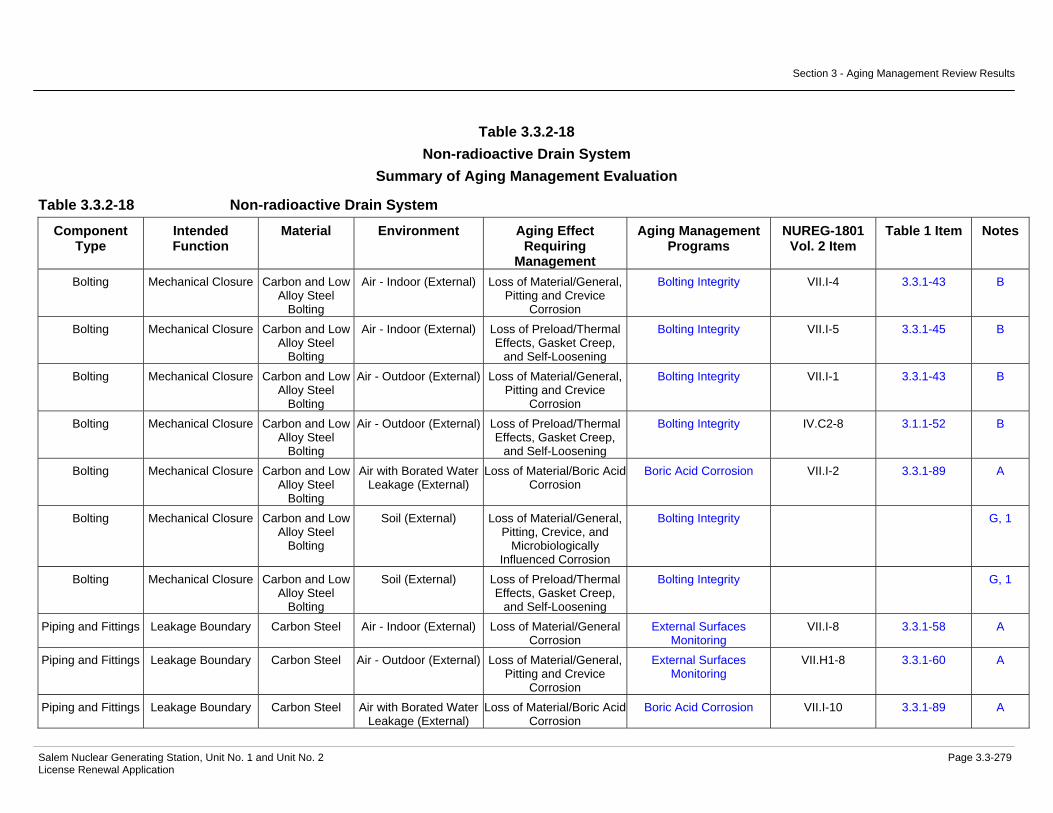
Management Evaluation...............................................................3.3-269 Table 3.3.2-18 Non-radioactive Drain System Summary of Aging Management
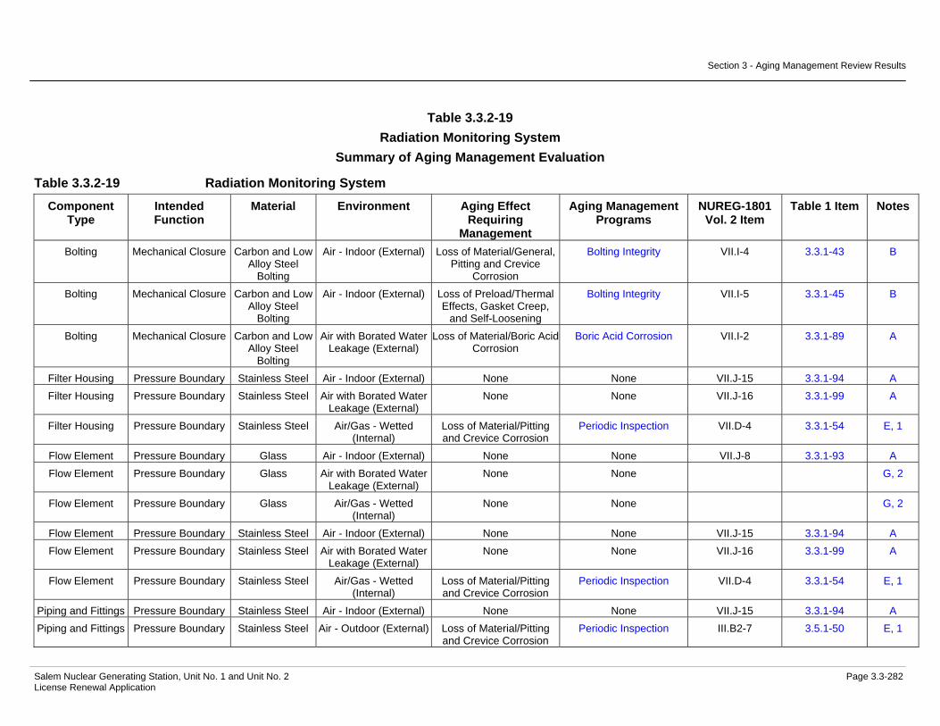
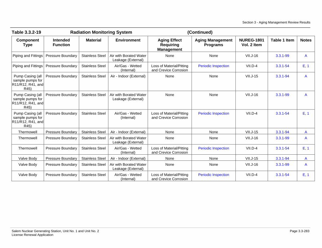
Evaluation.....................................................................................3.3-279 Table 3.3.2-19 Radiation Monitoring System Summary of Aging Management
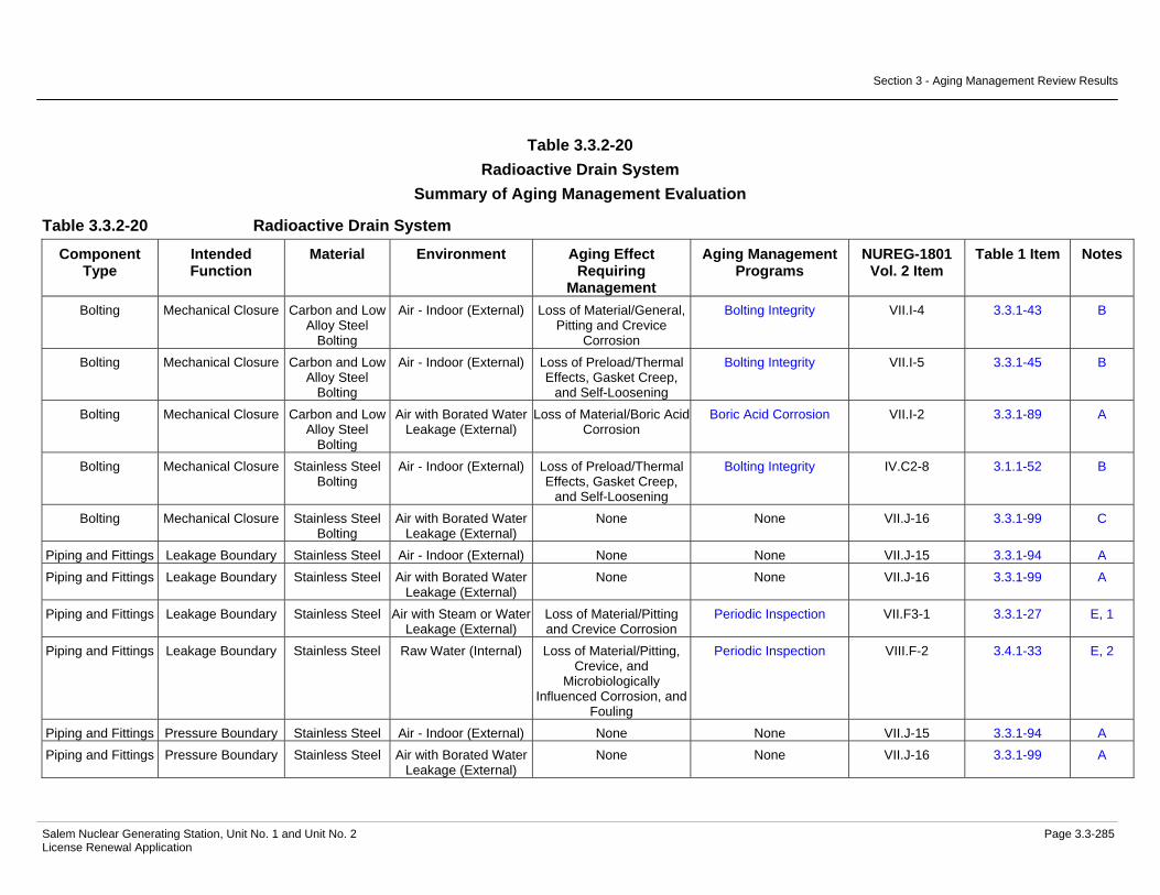
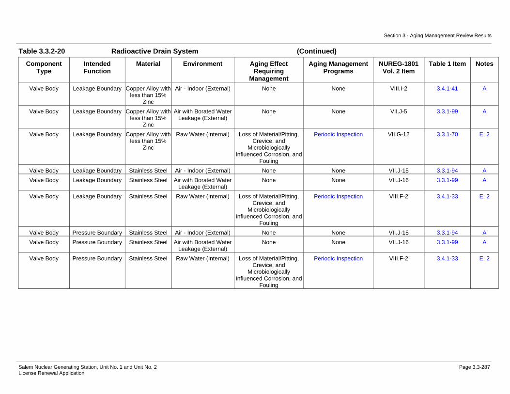
Evaluation.....................................................................................3.3-282 Table 3.3.2-20 Radioactive Drain System Summary of Aging Management
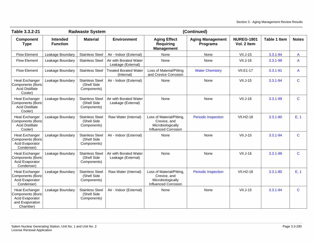
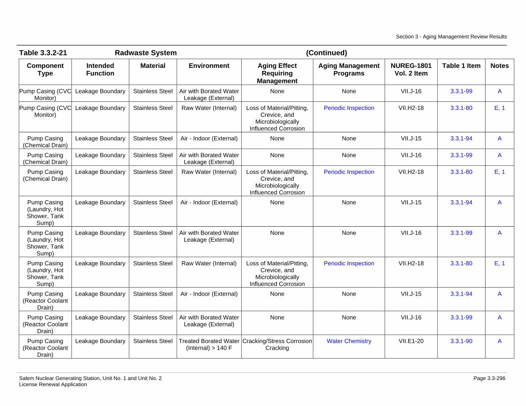
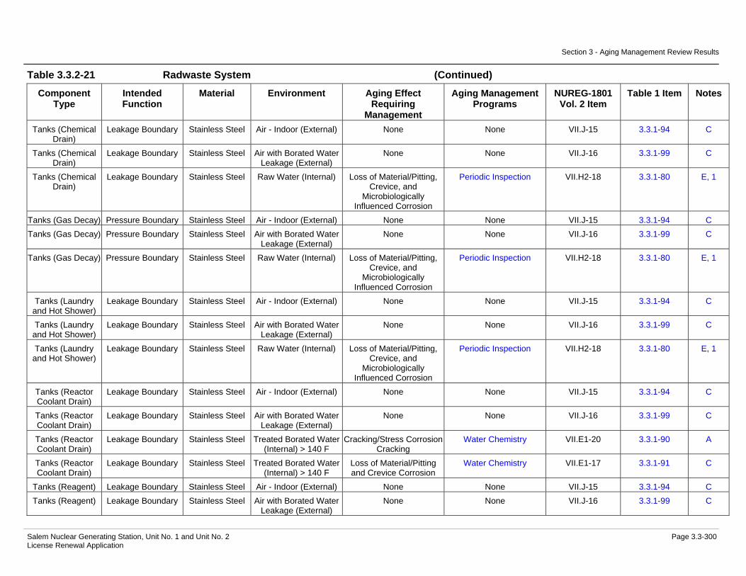
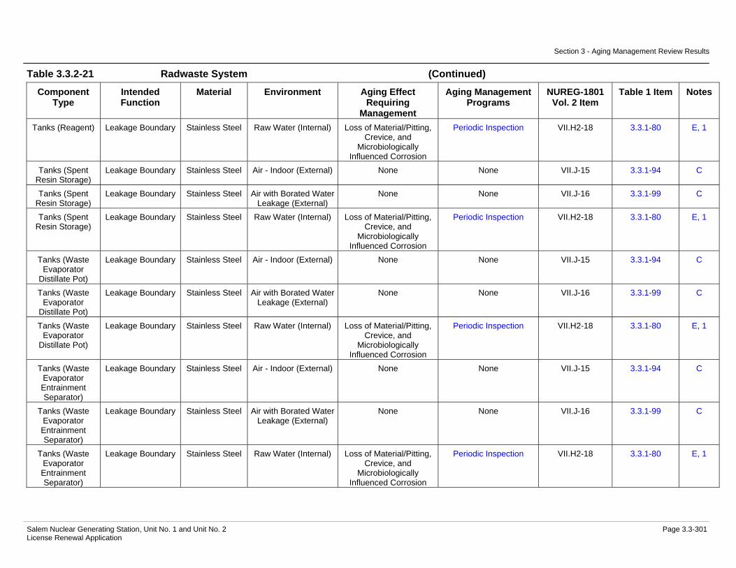
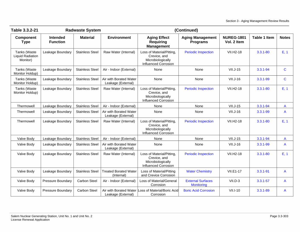
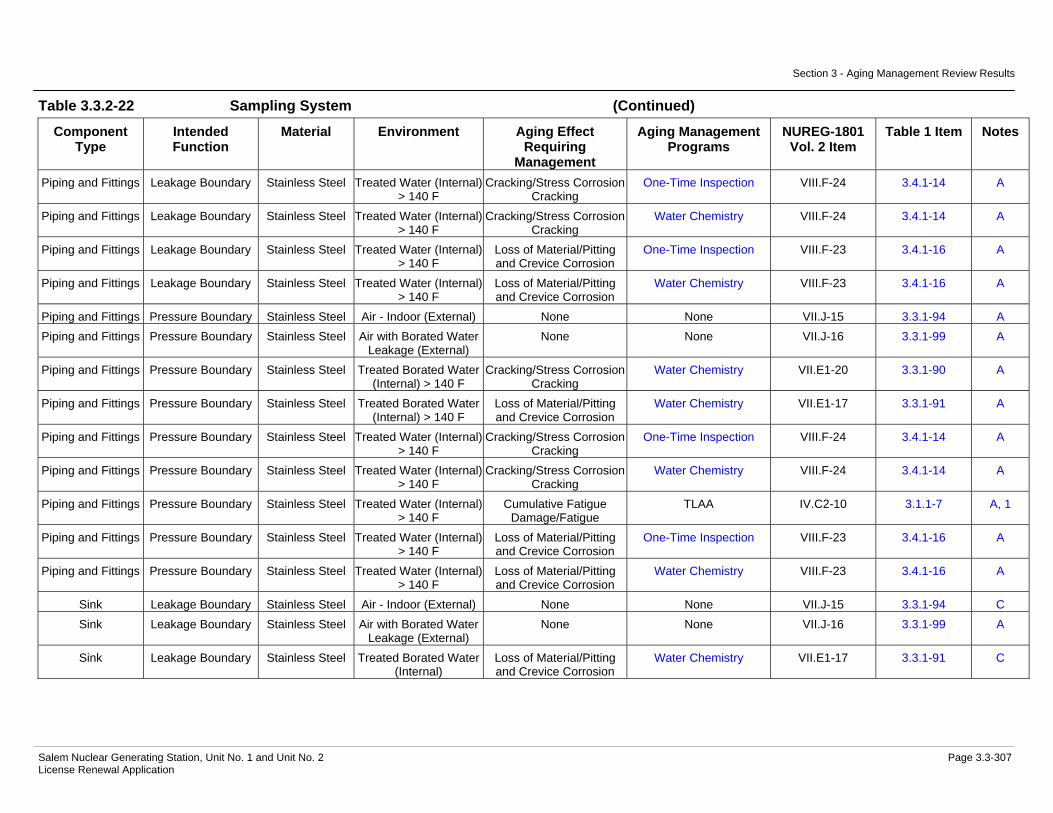
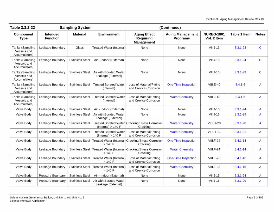
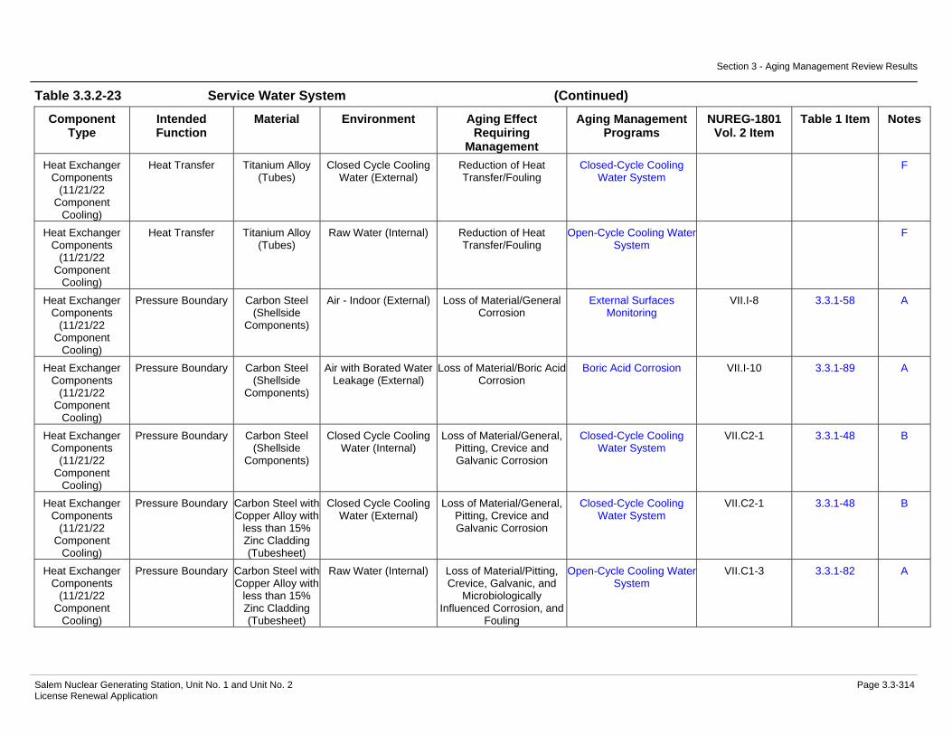
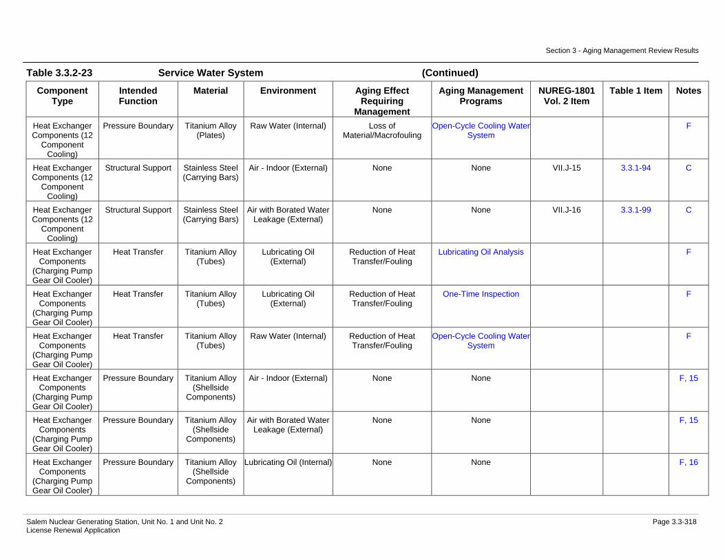
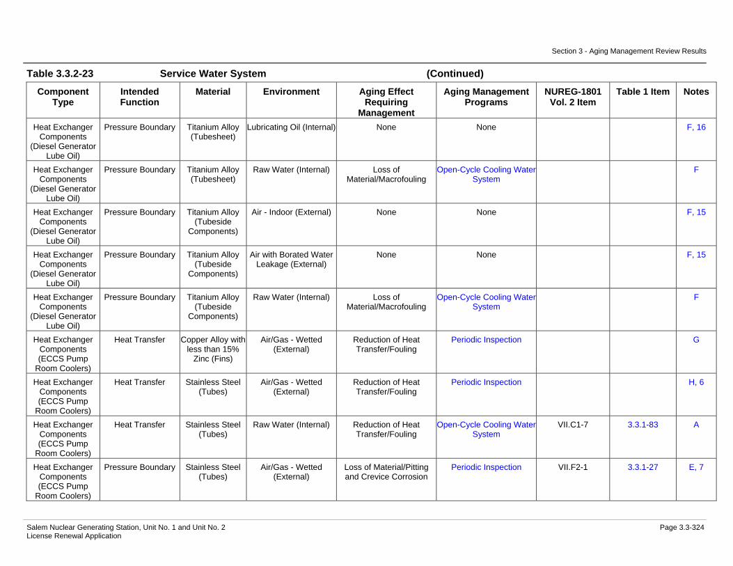
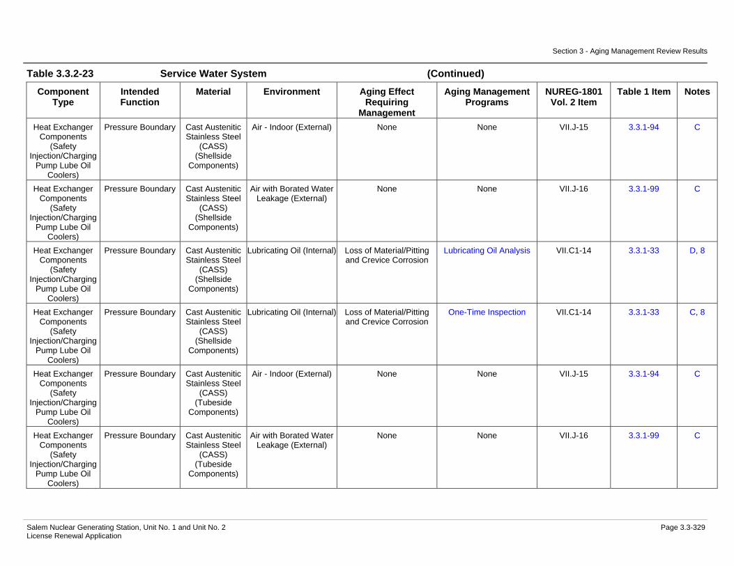
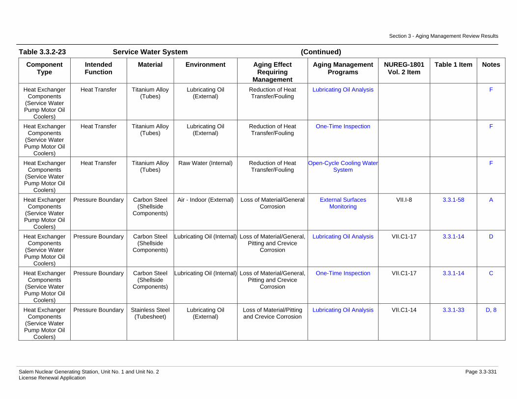
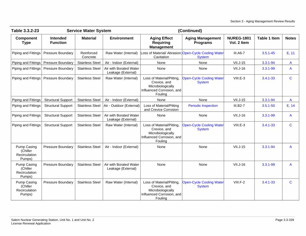
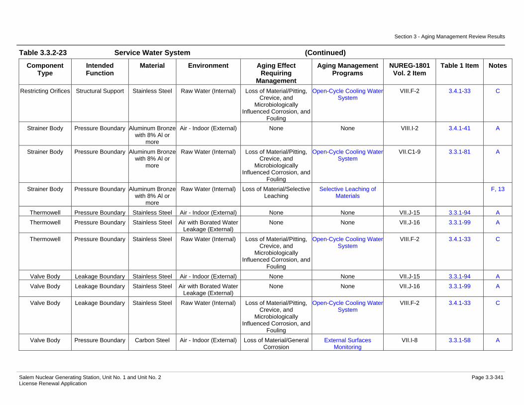
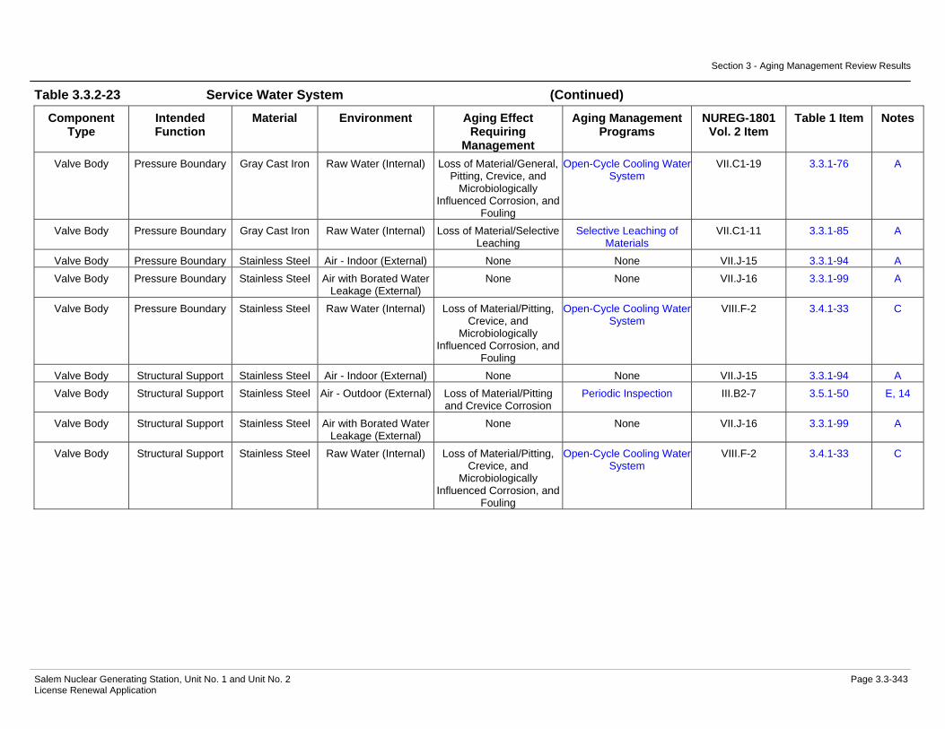
Evaluation.....................................................................................3.3-285 Table 3.3.2-21 Radwaste System Summary of Aging Management Evaluation ..3.3-289 Table 3.3.2-22 Sampling System Summary of Aging Management Evaluation ...3.3-306 Table 3.3.2-23 Service Water System Summary of Aging Management
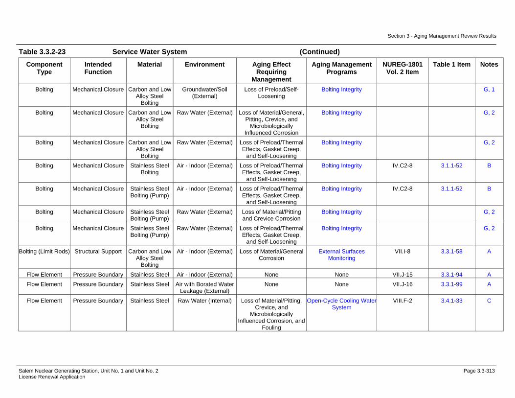
Evaluation.....................................................................................3.3-312 Table 3.3.2-24 Service Water Ventilation System Summary of Aging
Management Evaluation...............................................................3.3-346 Table 3.3.2-25 Spent Fuel Cooling System Summary of Aging Management
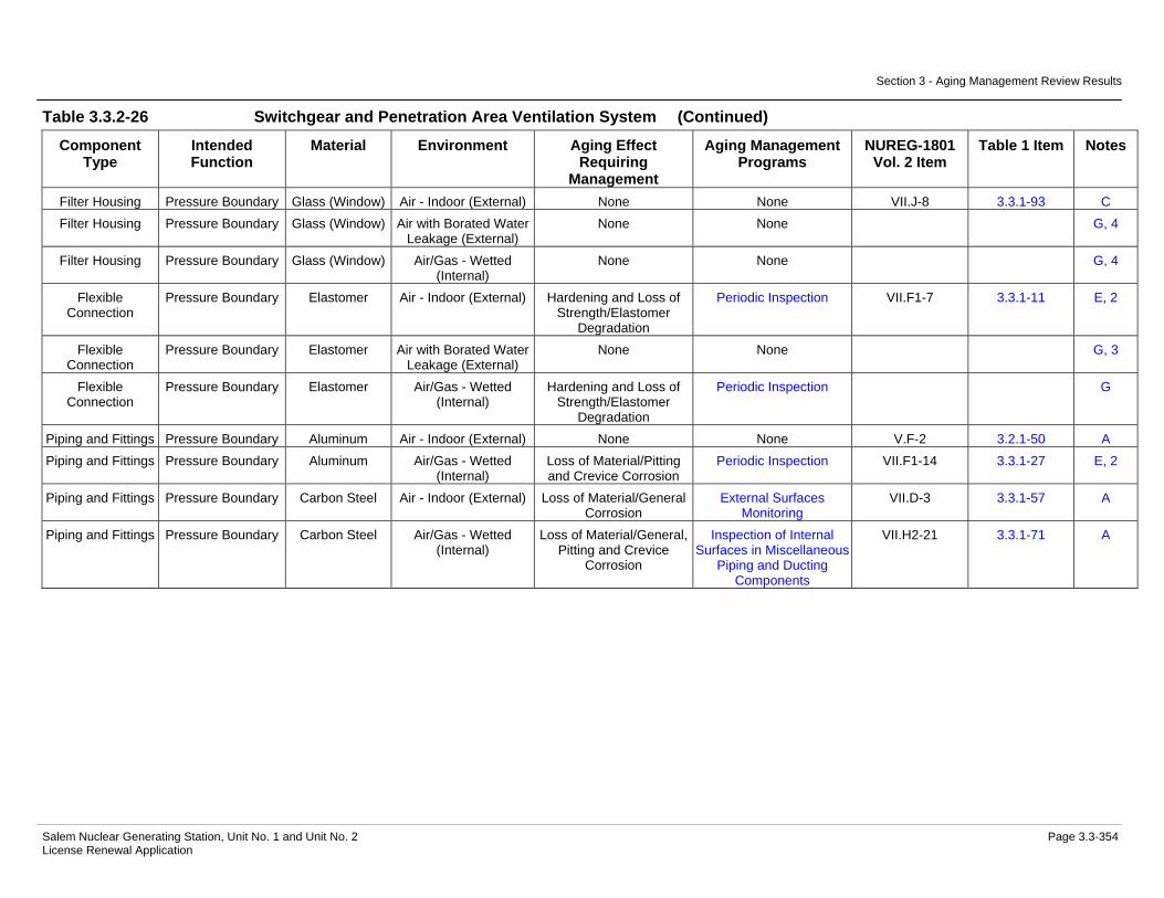
Evaluation.....................................................................................3.3-348 Table 3.3.2-26 Switchgear and Penetration Area Ventilation System Summary
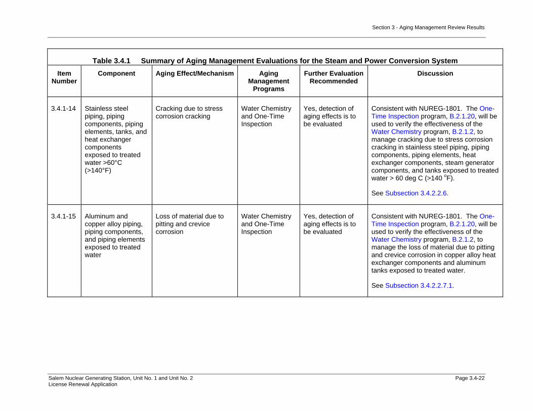
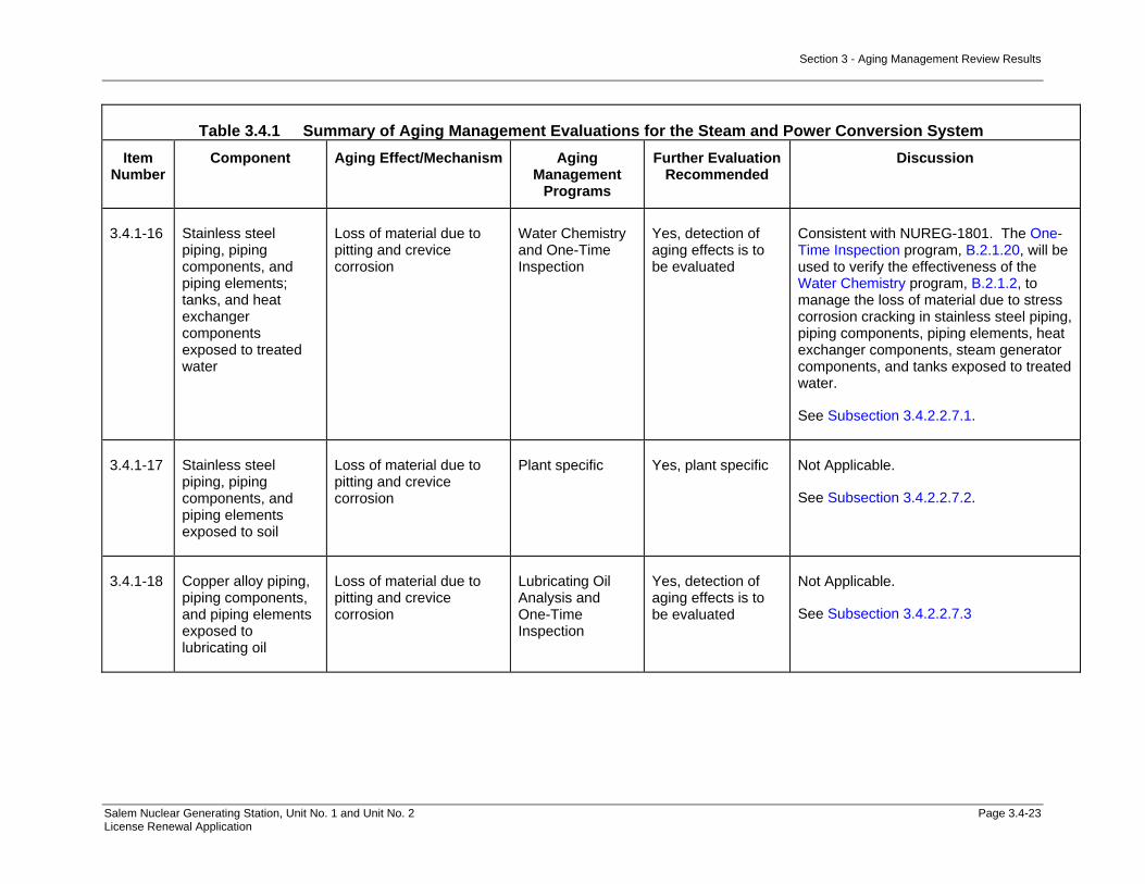
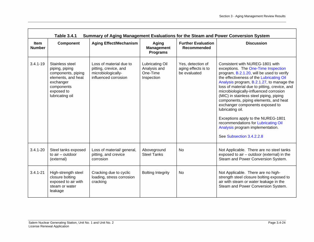
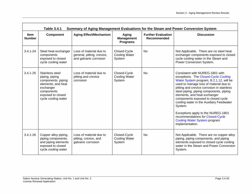
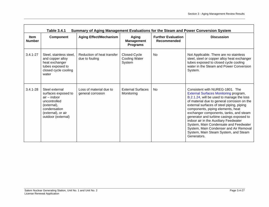
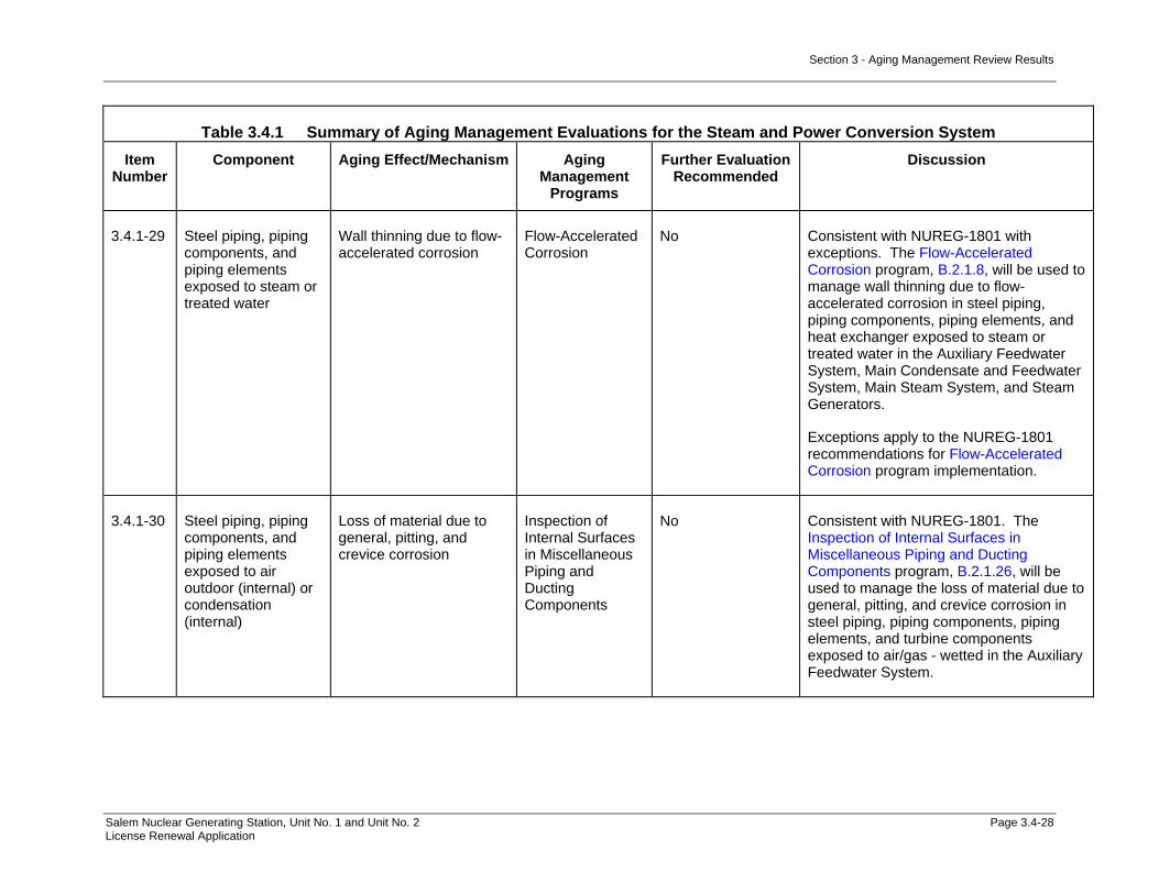
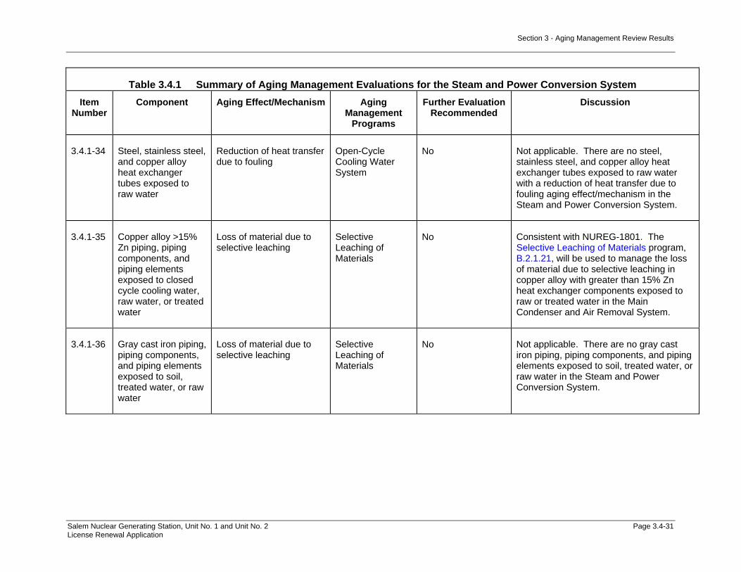
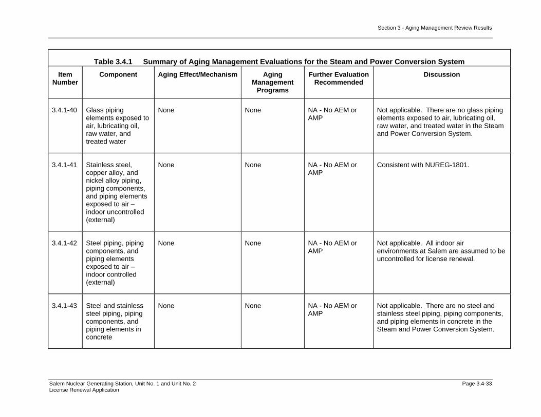
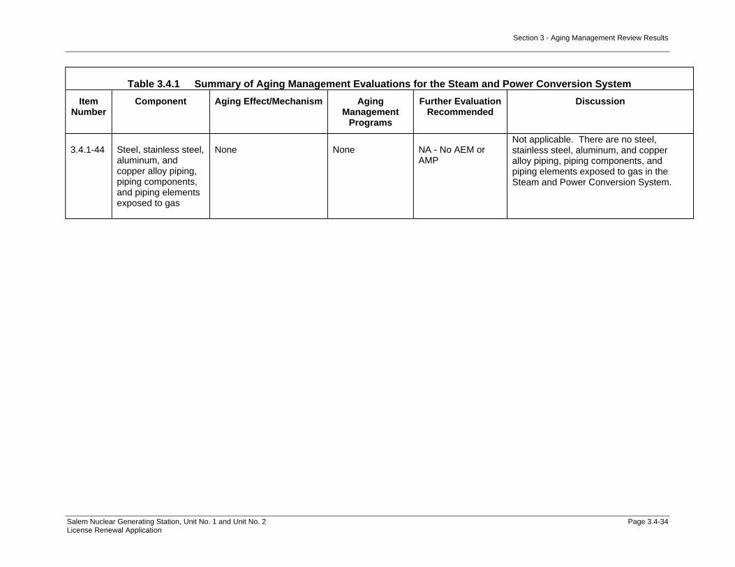
of Aging Management Evaluation.................................................3.3-352 Table 3.4.1 Summary of Aging Management Evaluations for the Steam and
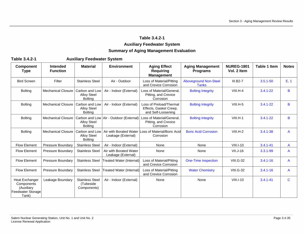
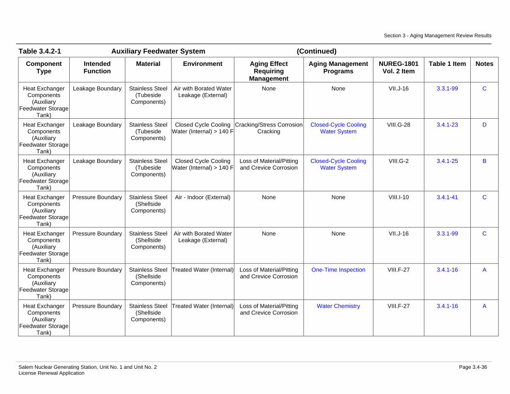
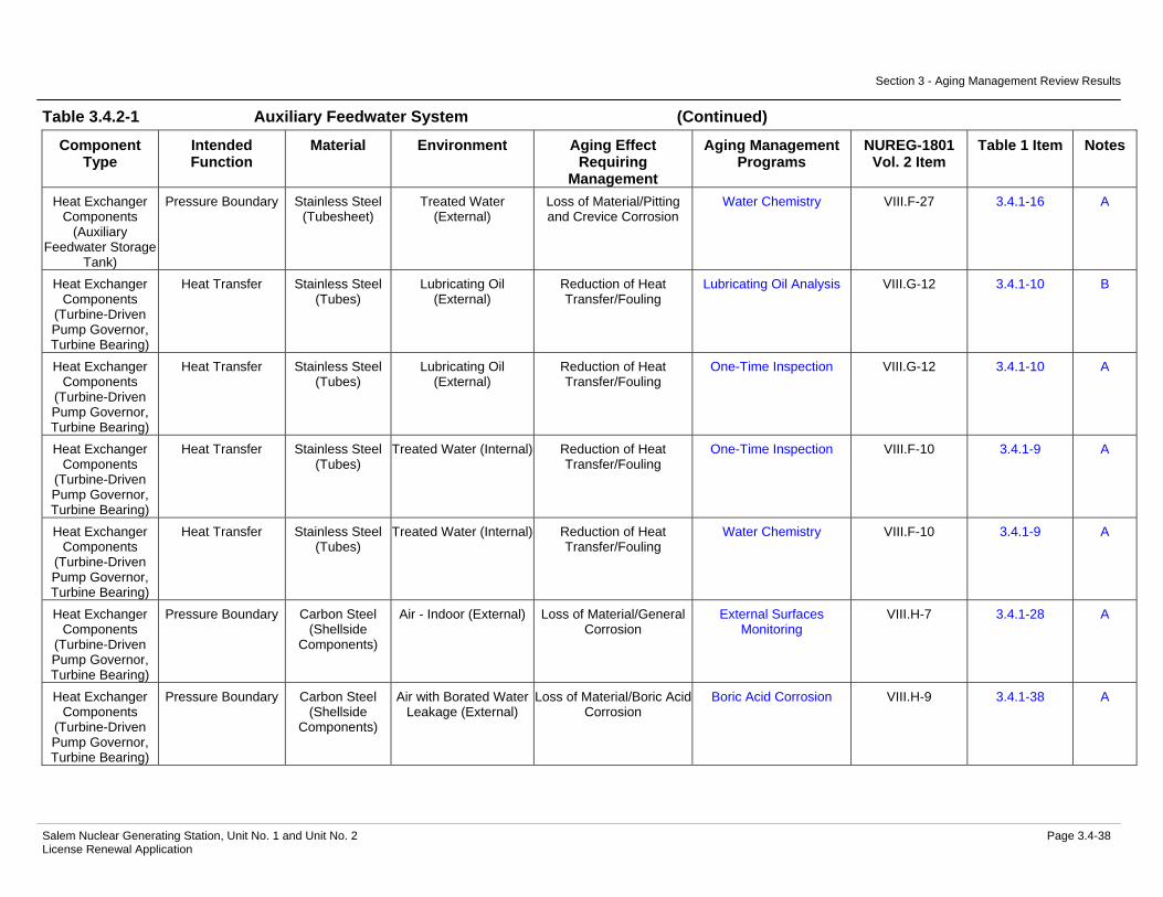
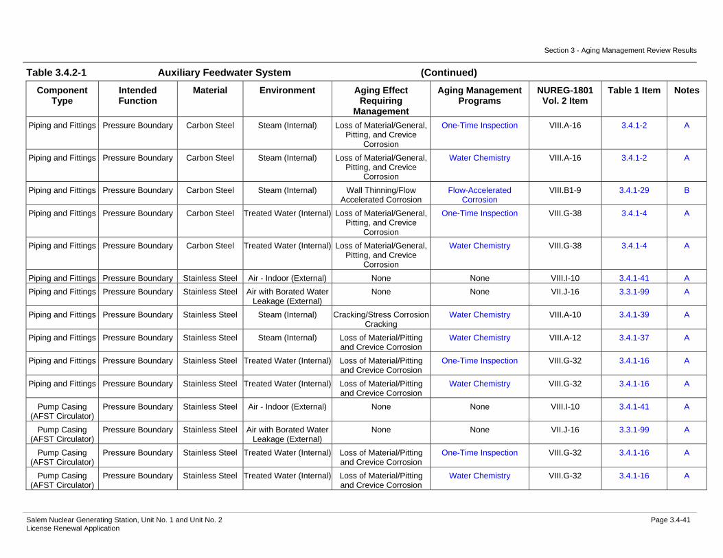
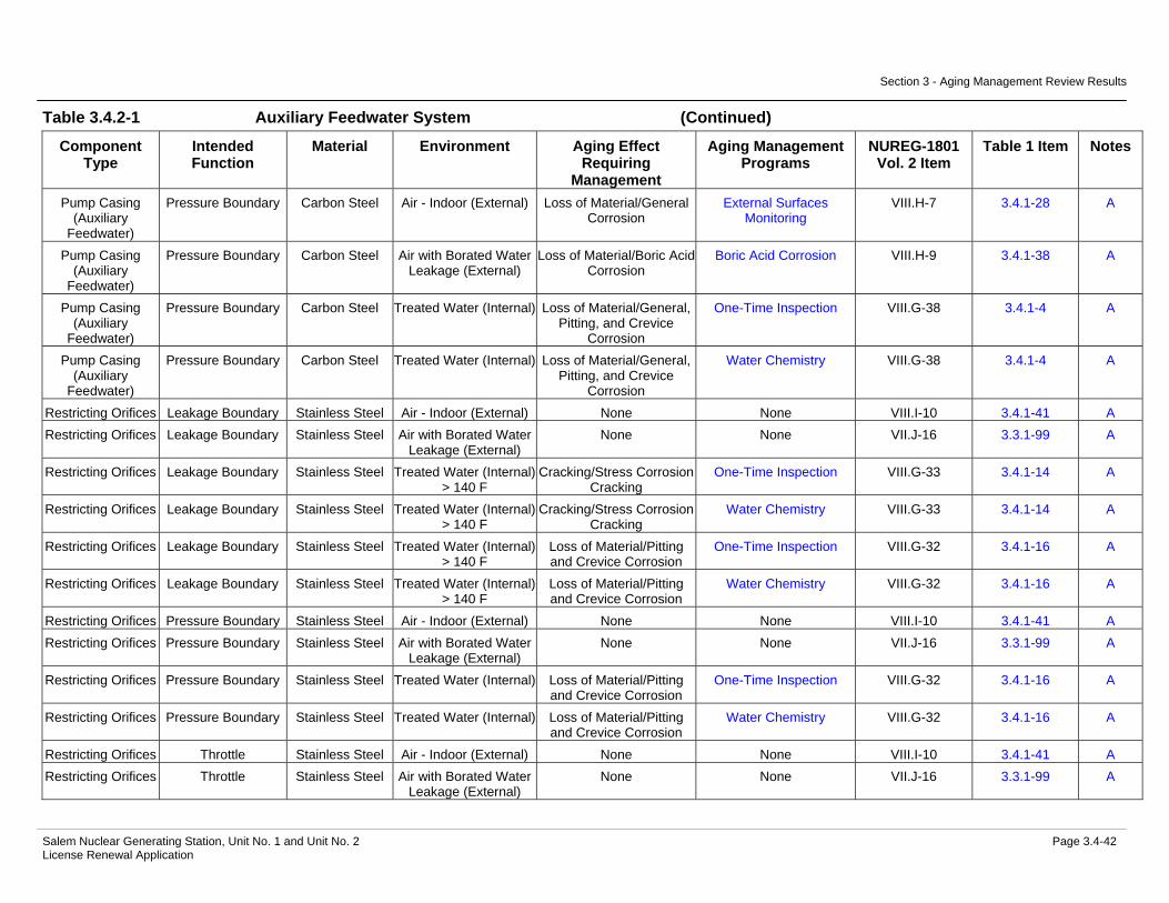
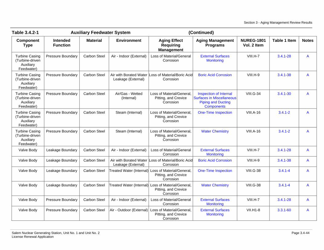
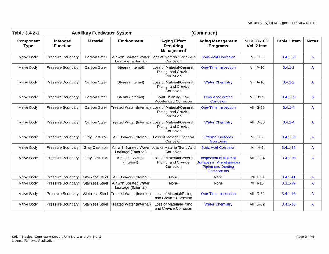
Power Conversion System ................................................................... 3.4.16 Table 3.4.2-1 Auxiliary Feedwater System Summary of Aging Management
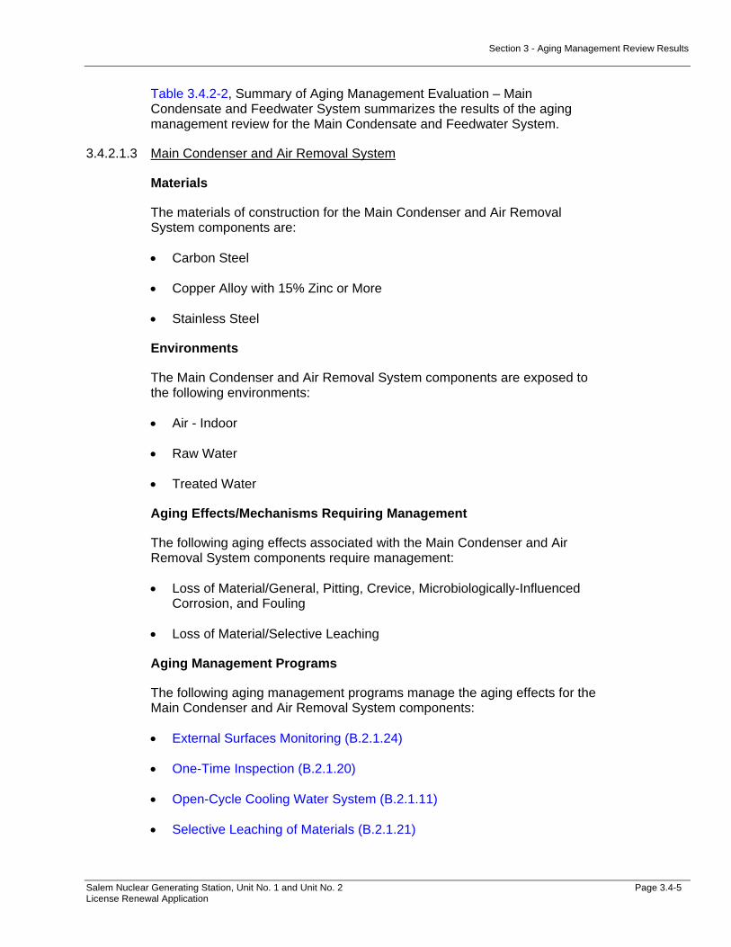
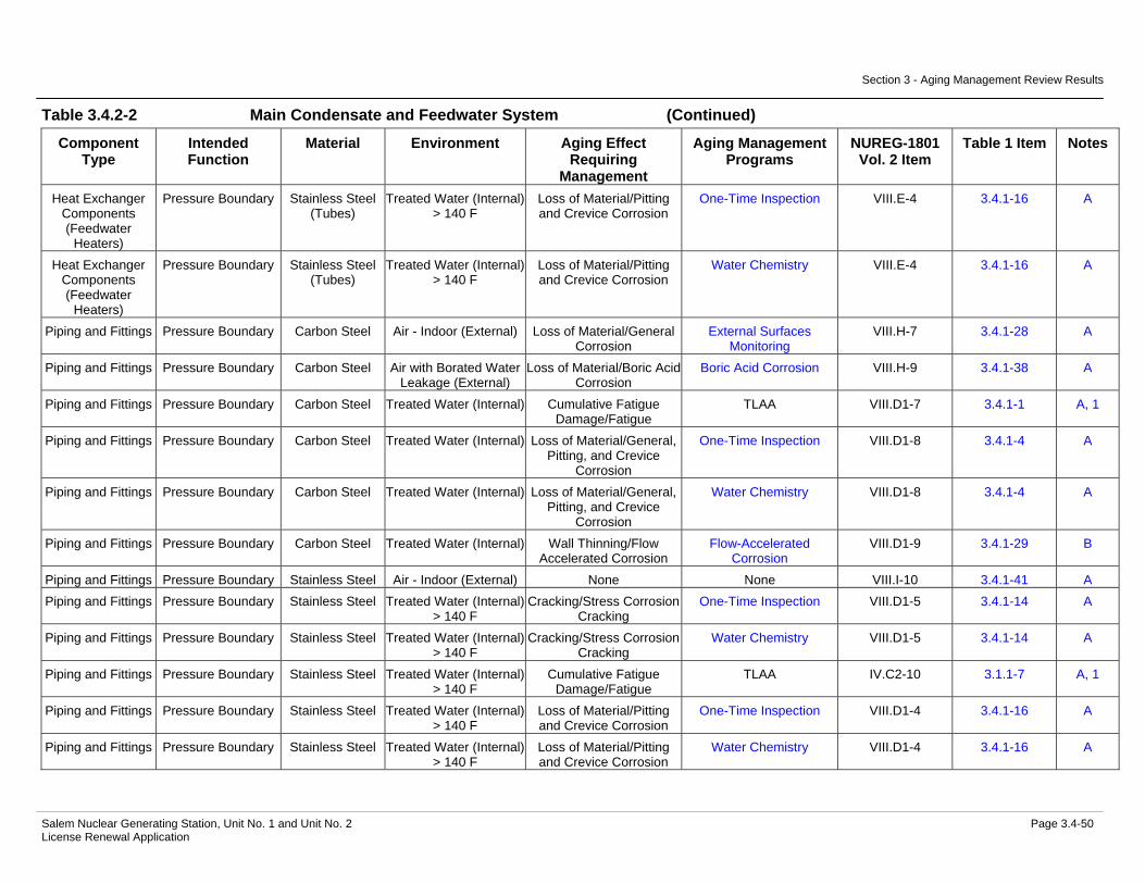
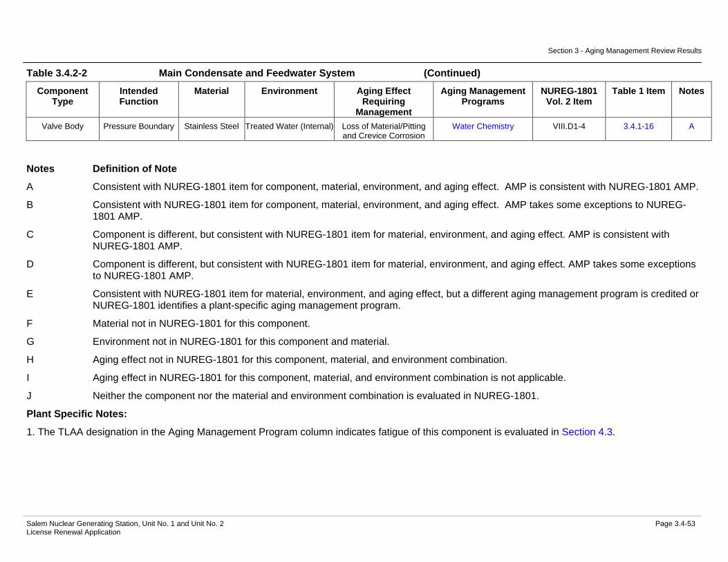
Evaluation.......................................................................................3.4-35 Table 3.4.2-2 Main Condensate and Feedwater System Summary of Aging
Management Evaluation.................................................................3.4-47 Table 3.4.2-3 Main Condenser and Air Removal System Summary of Aging
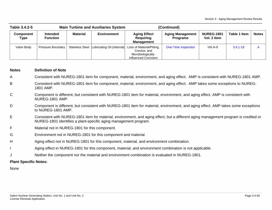
Management Evaluation.................................................................3.4-54 Table 3.4.2-4 Main Steam System Summary of Aging Management Evaluation .3.4-57 Table 3.4.2-5 Main Turbine and Auxiliaries System Summary of Aging
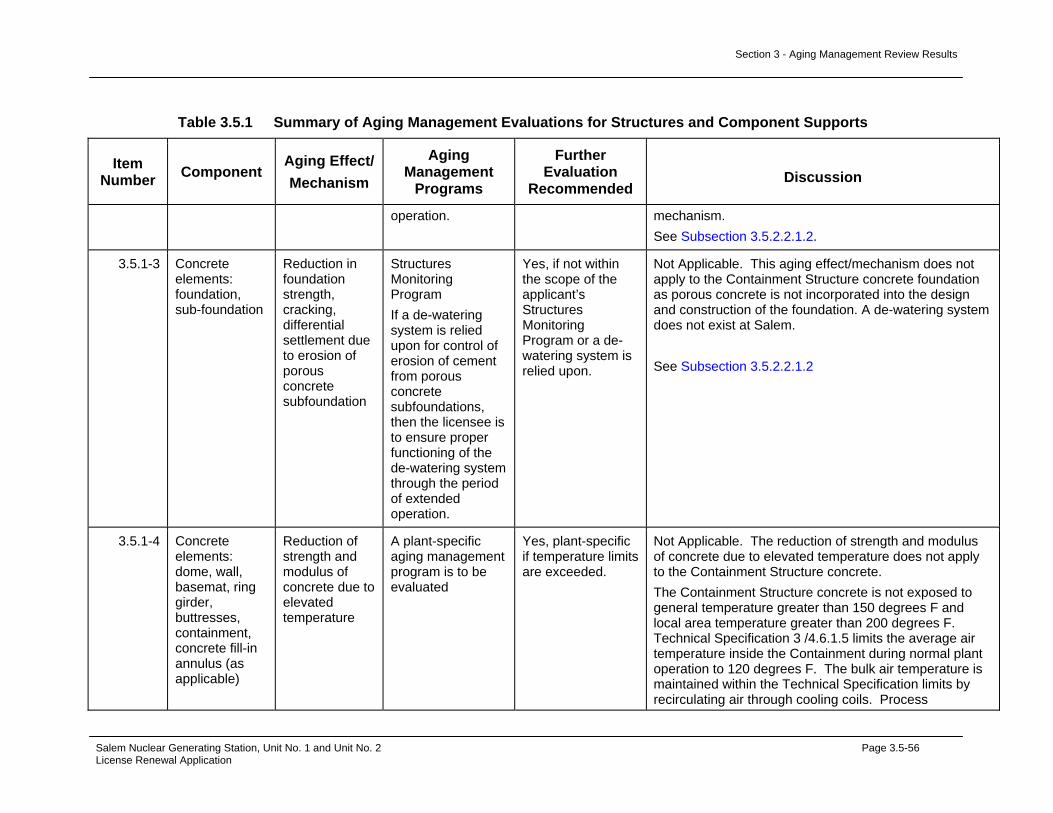
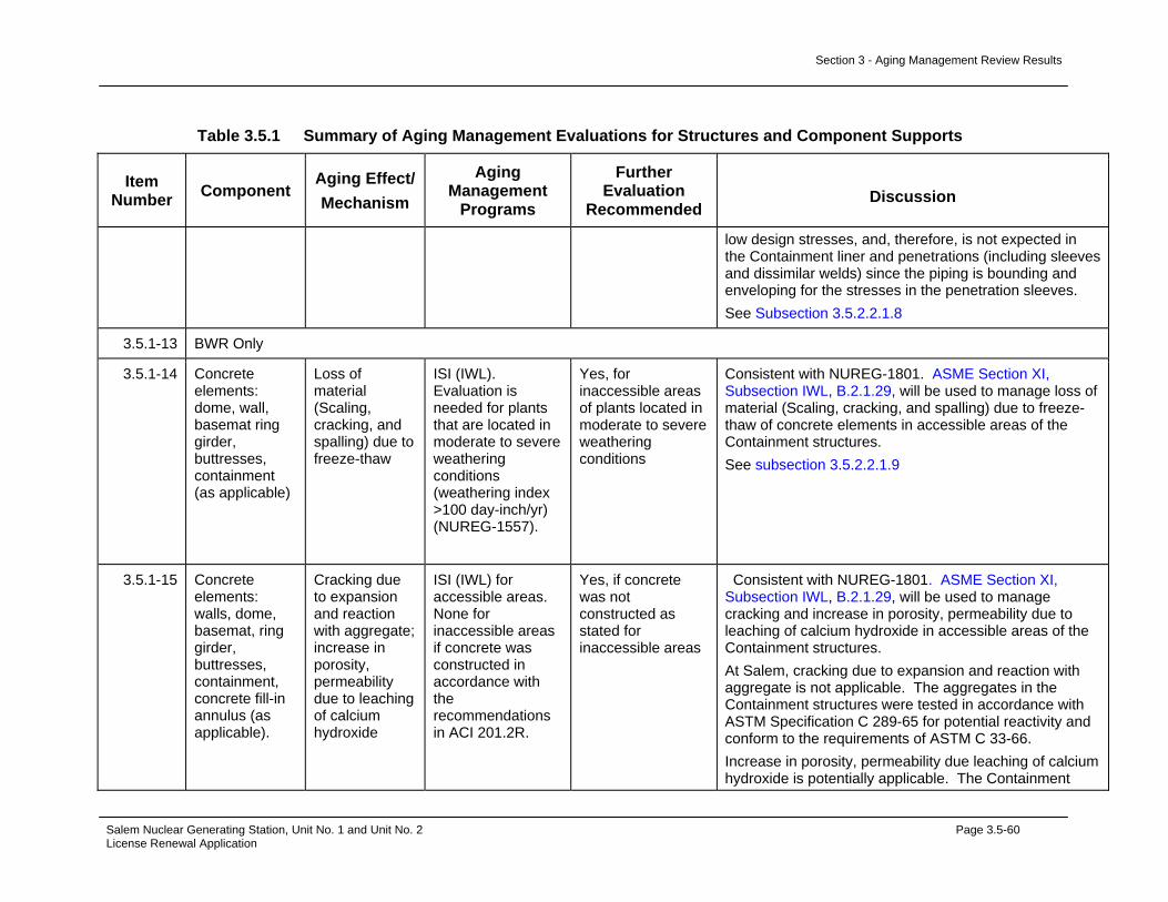
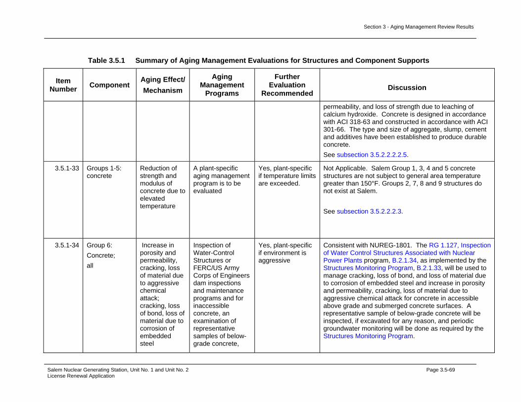
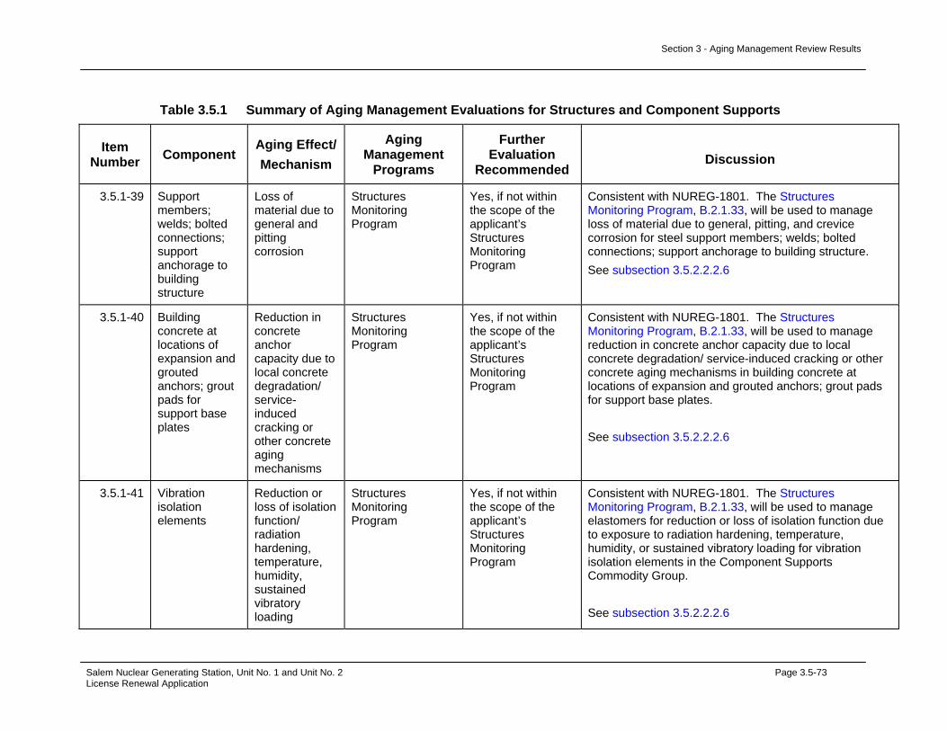
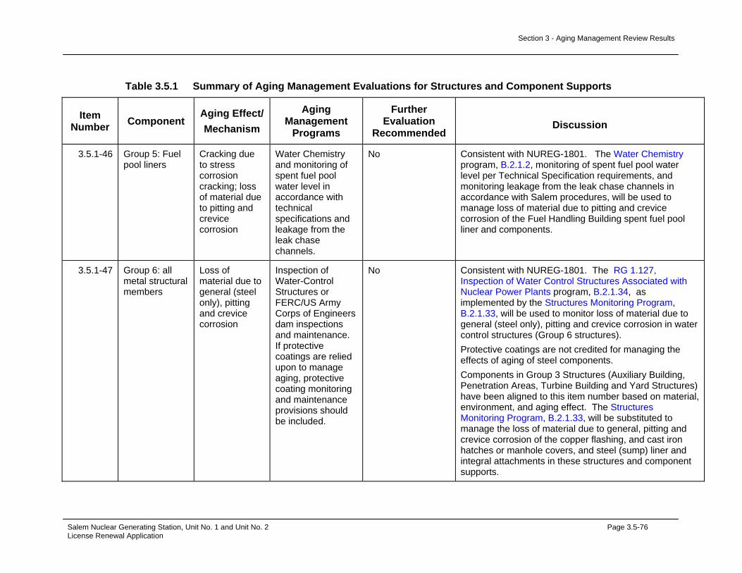
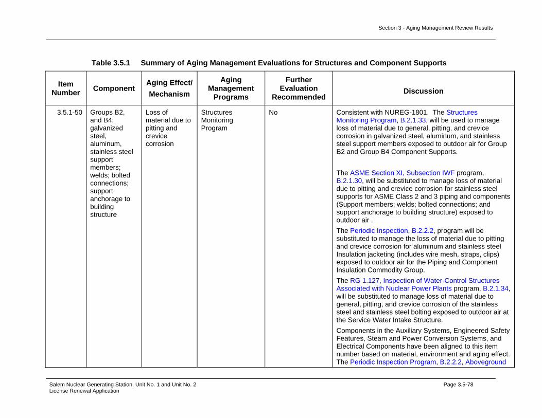
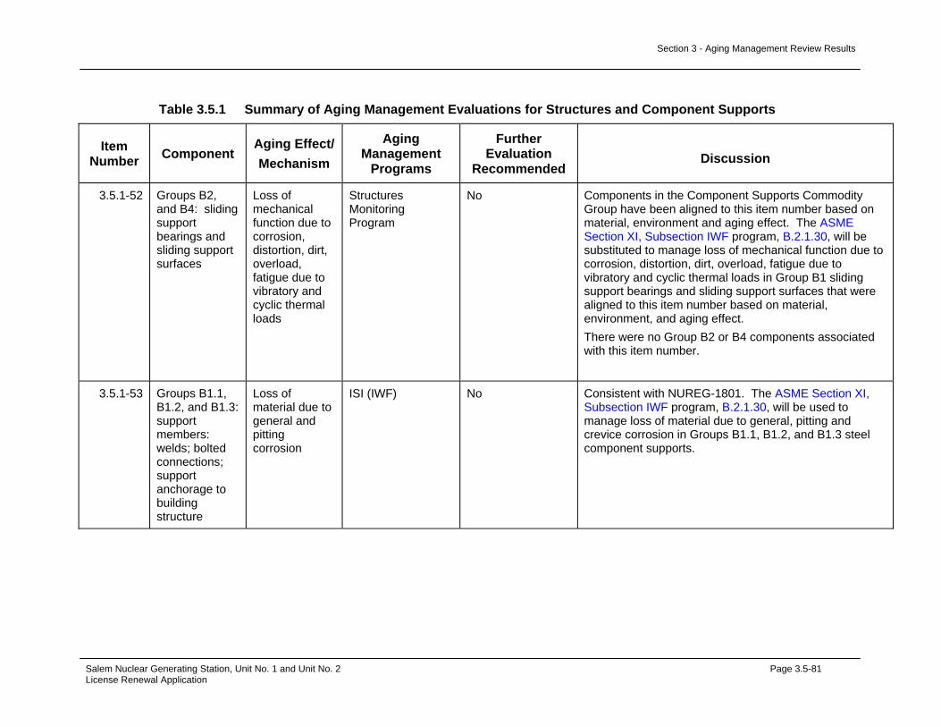
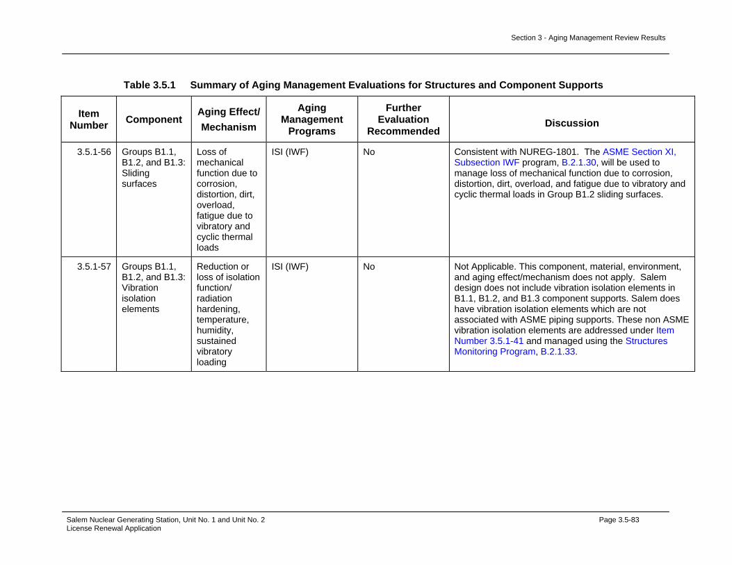
Management Evaluation.................................................................3.4-65 Table 3.5.1 Summary of Aging Management Evaluations for Structures and
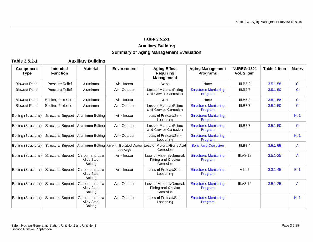
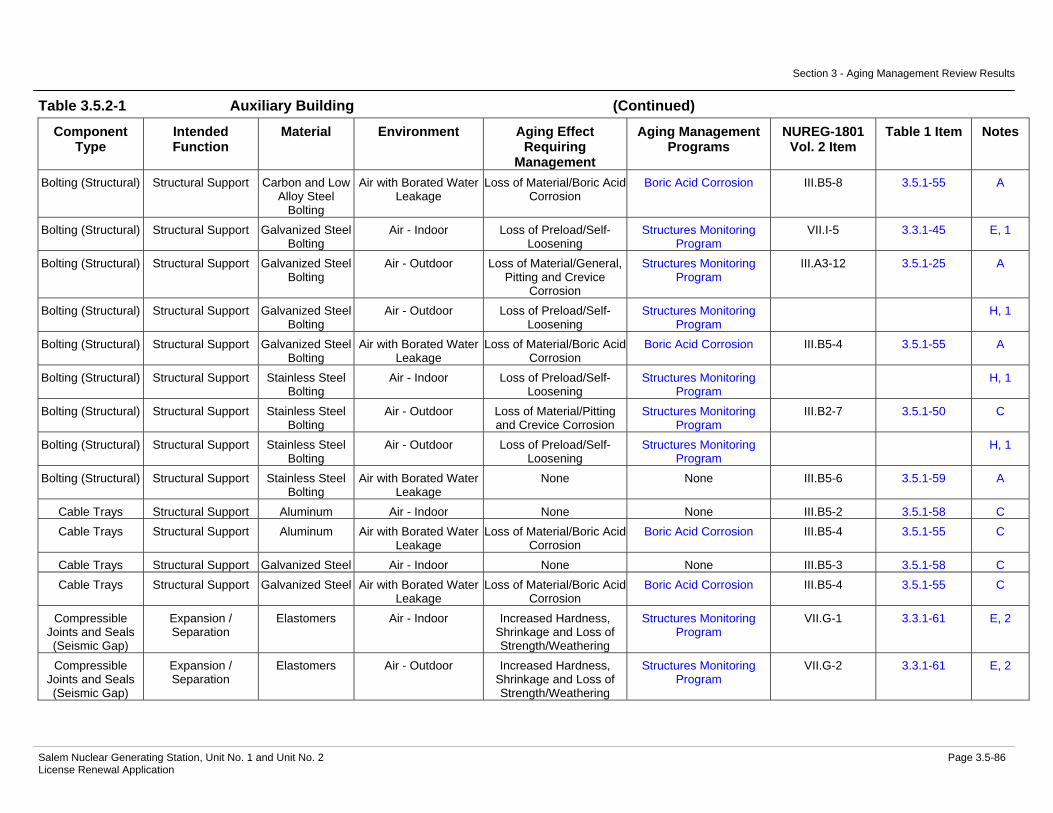
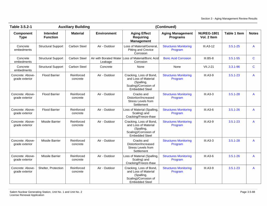
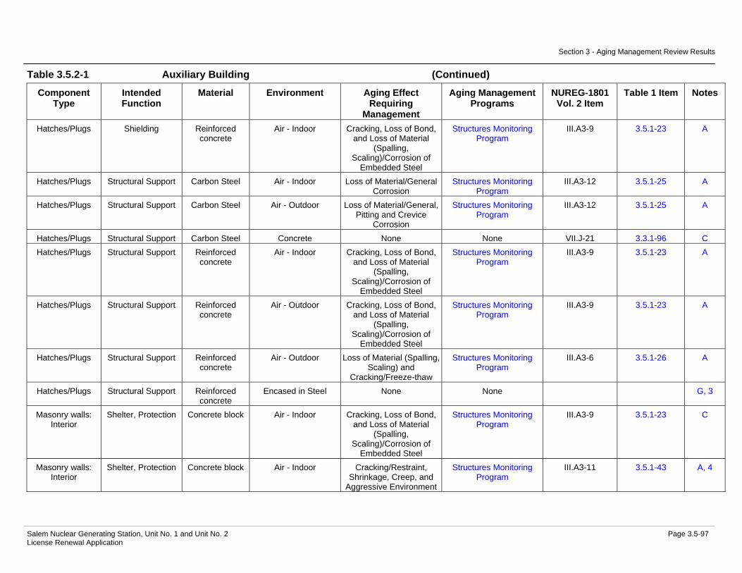
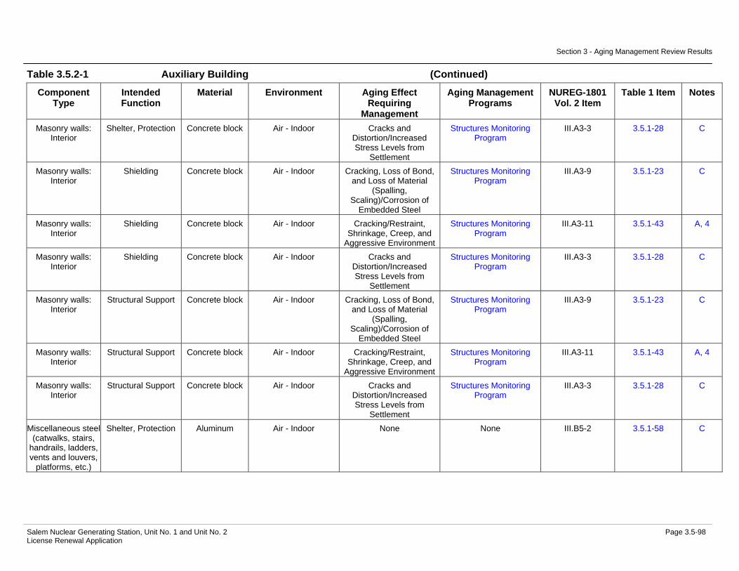
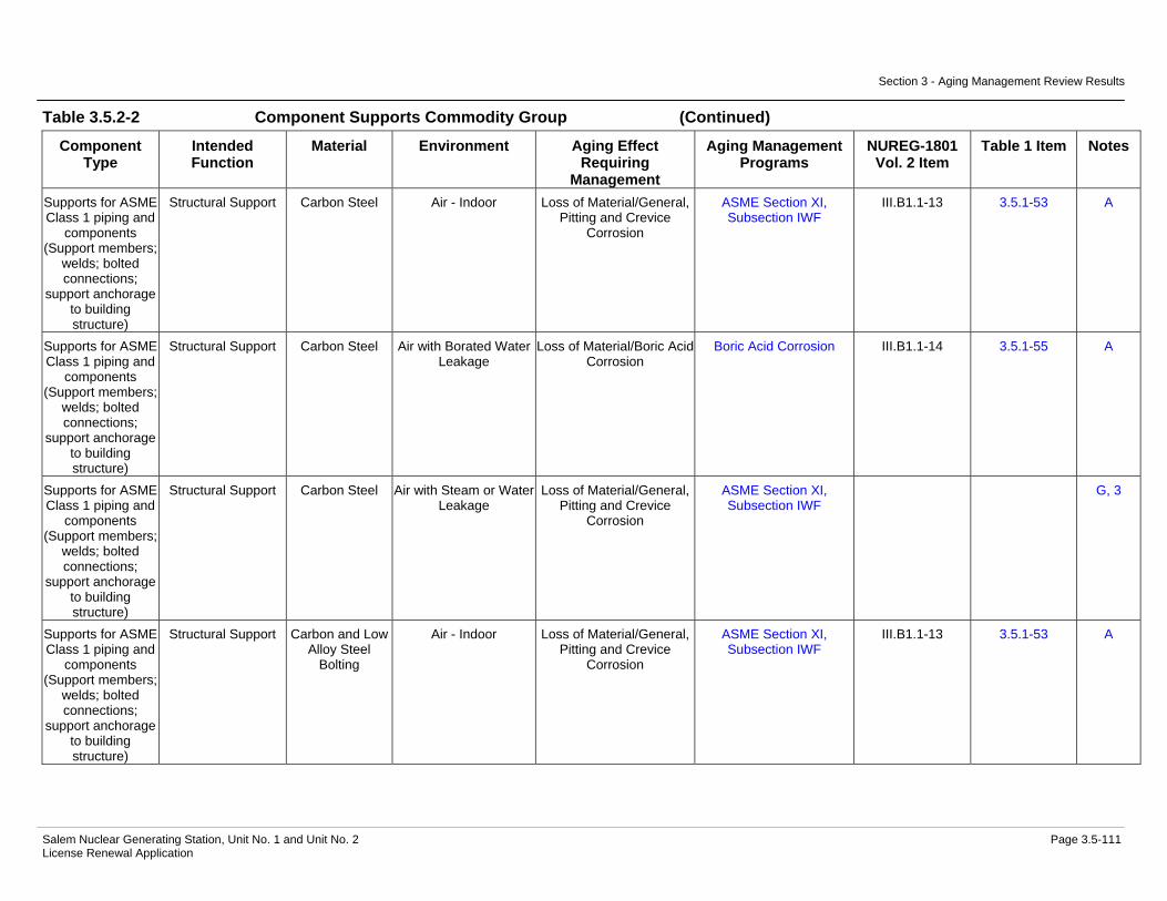
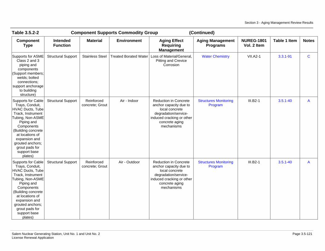
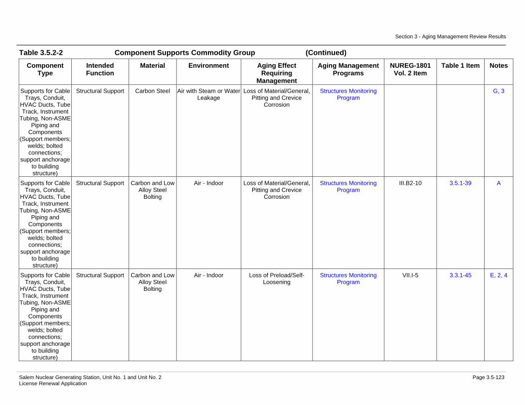
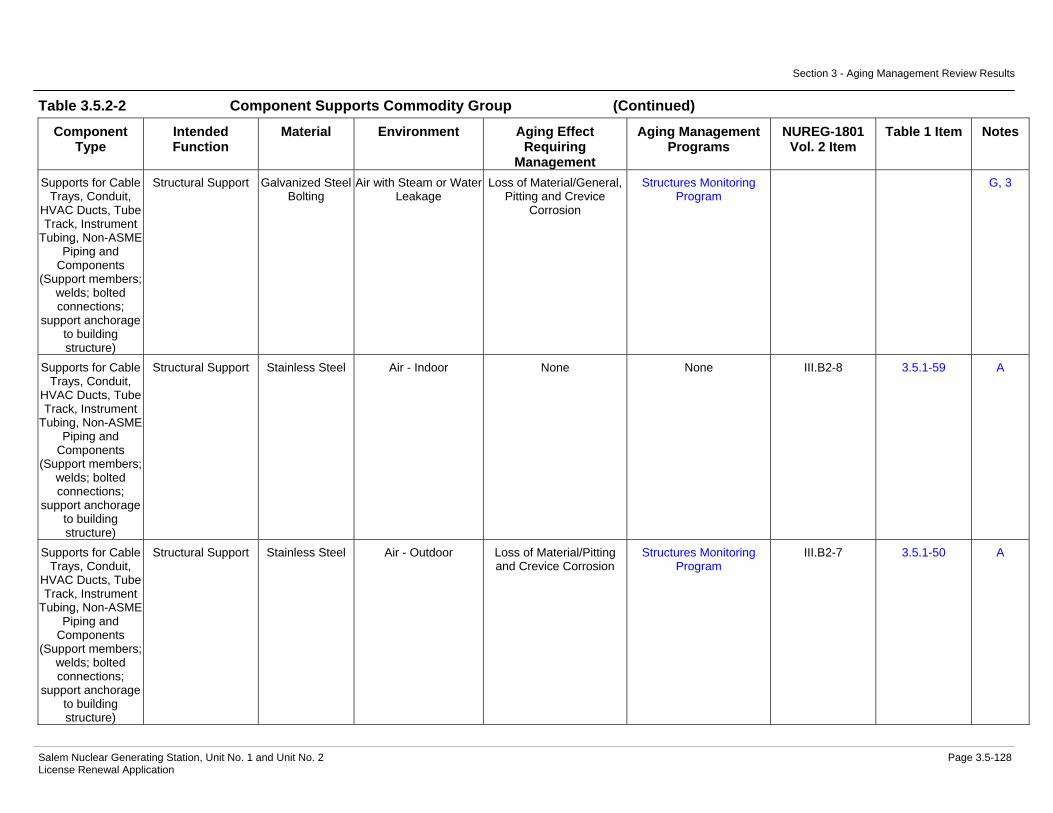
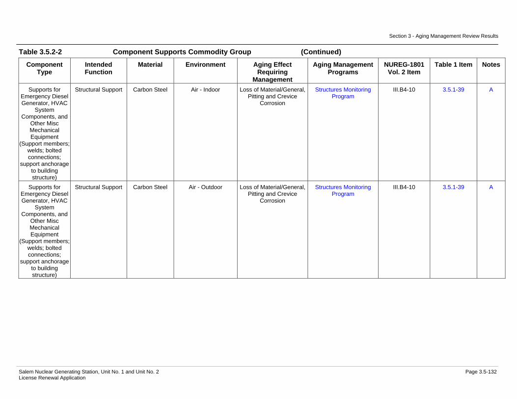
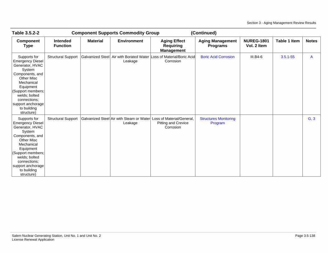
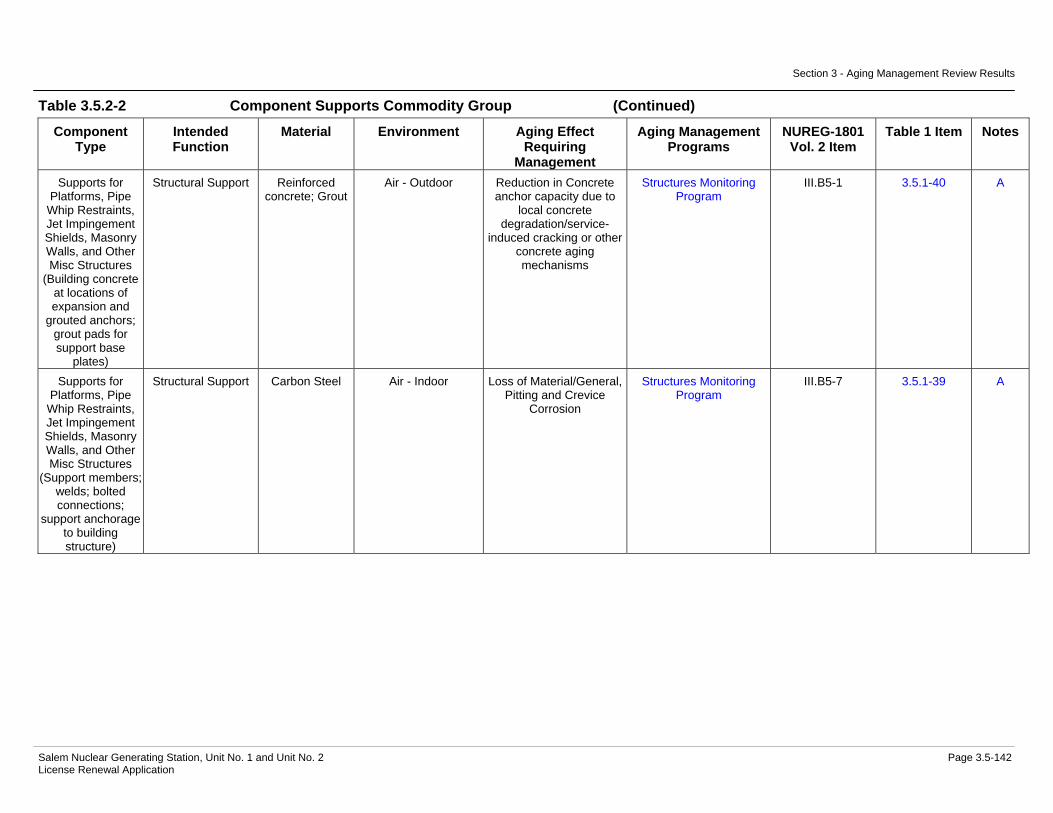
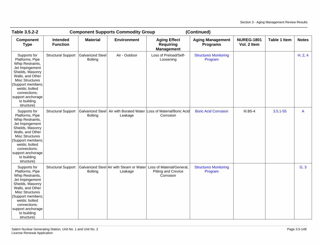
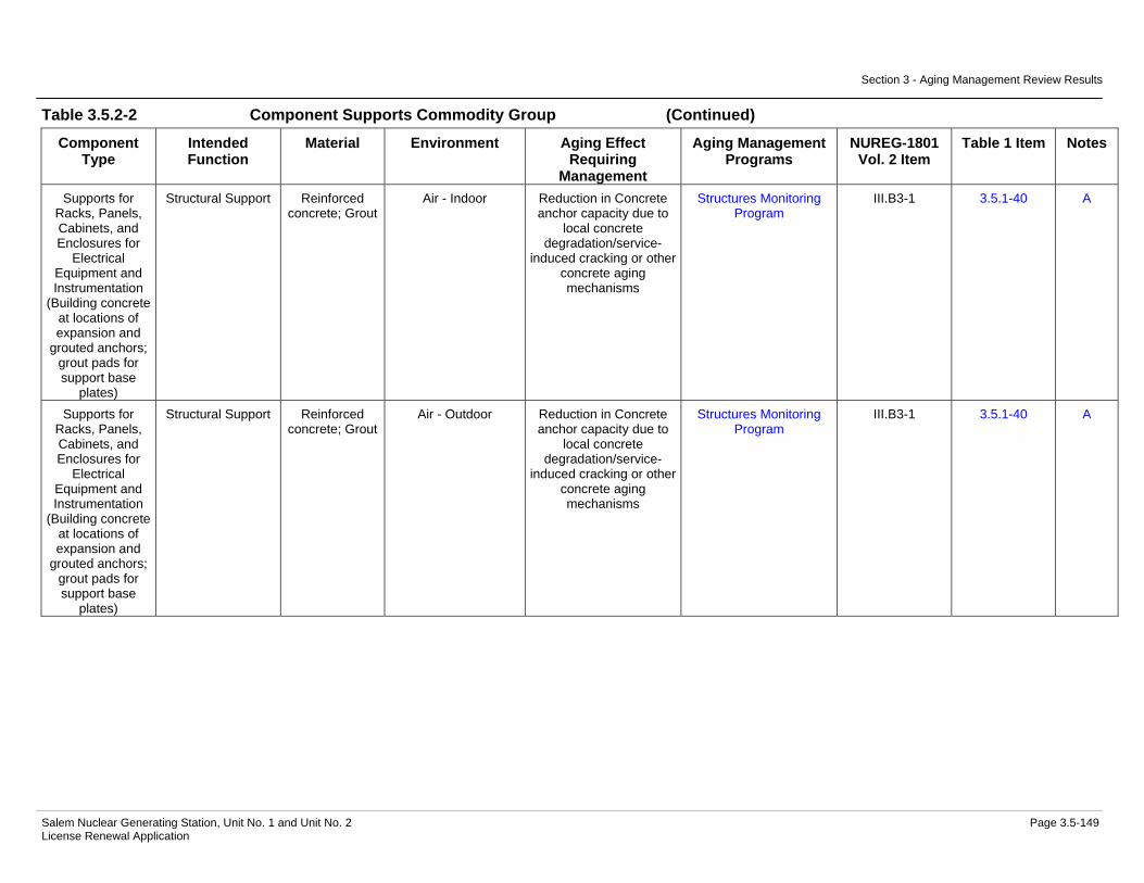
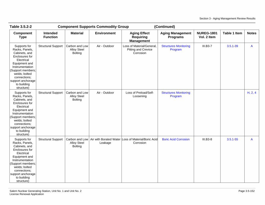
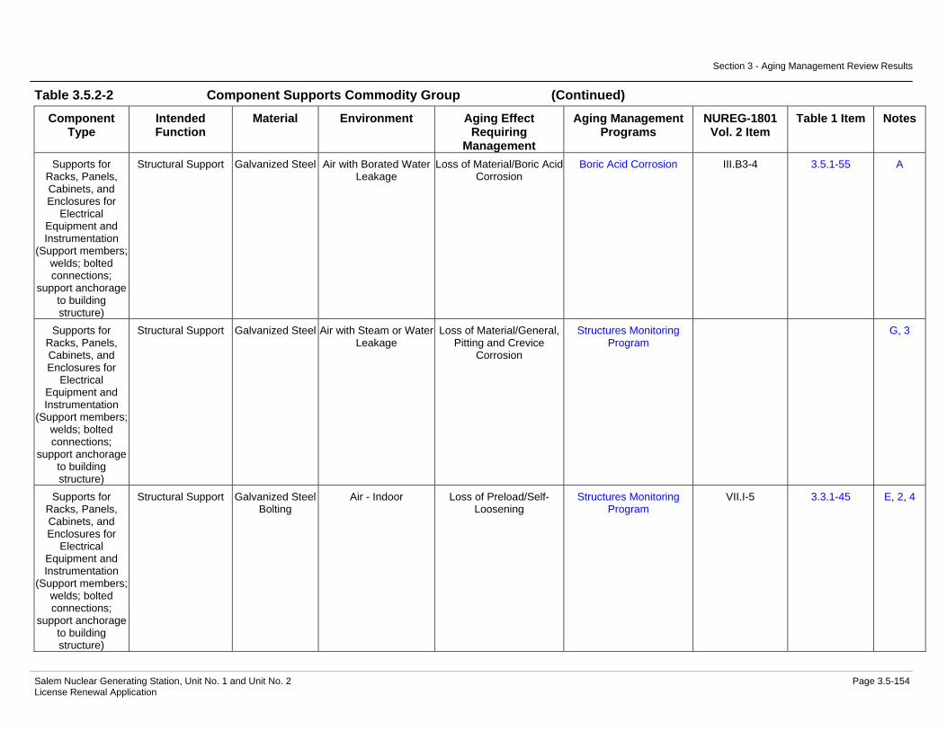
Component Supports............................................................................3.5-55 Table 3.5.2-1 Auxiliary Building Summary of Aging Management Evaluation......3.5-85 Table 3.5.2-2 Component Supports Commodity Group Summary of Aging
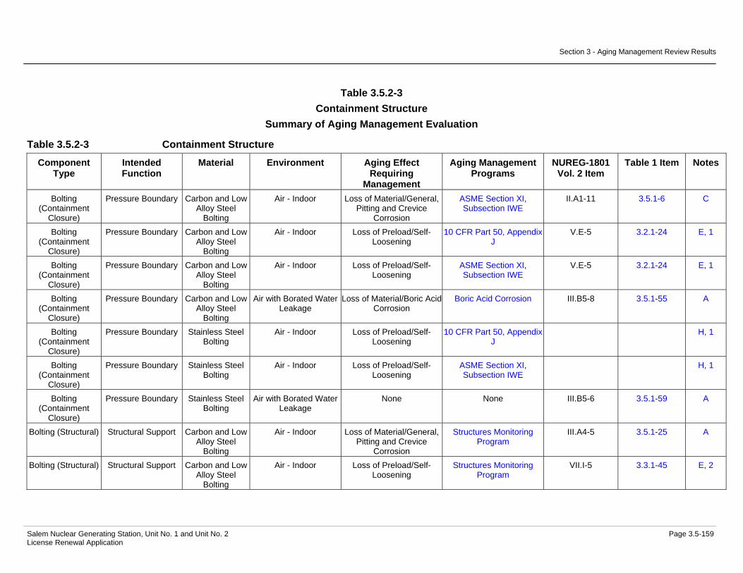
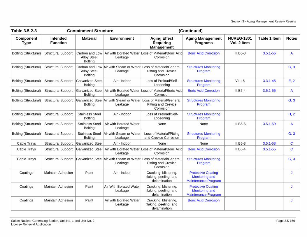
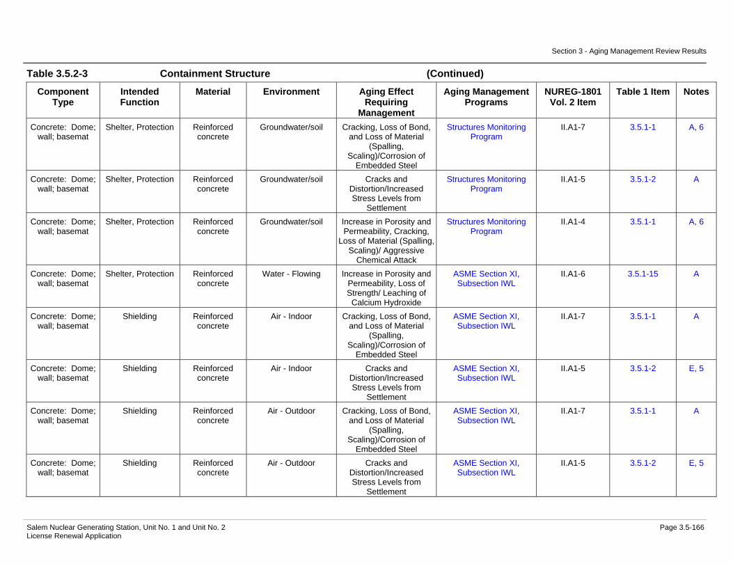
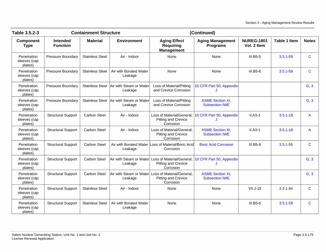
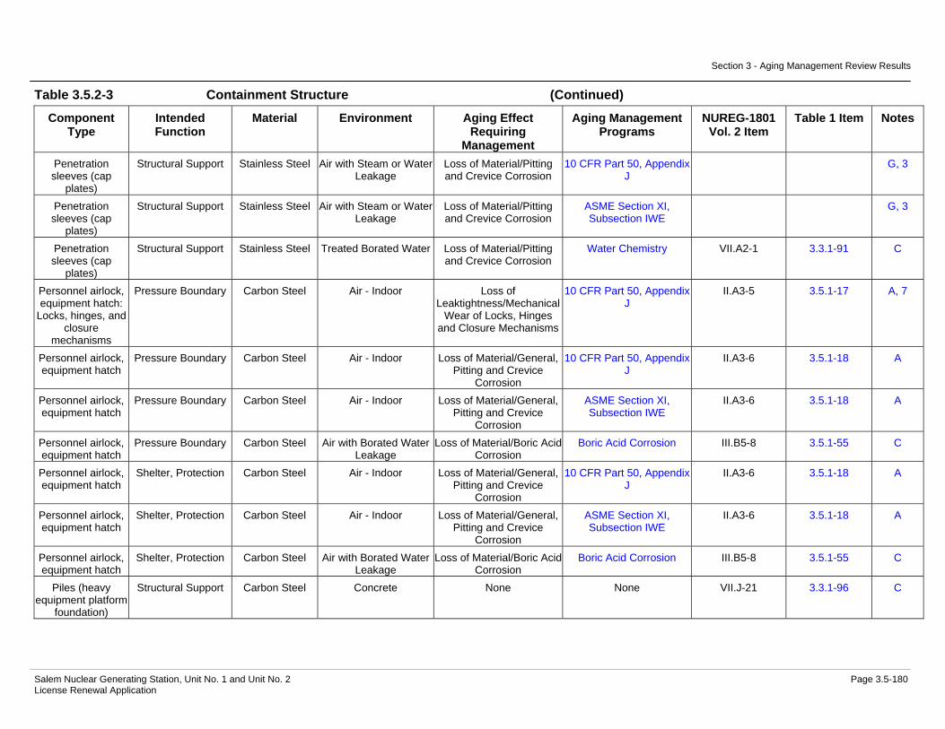
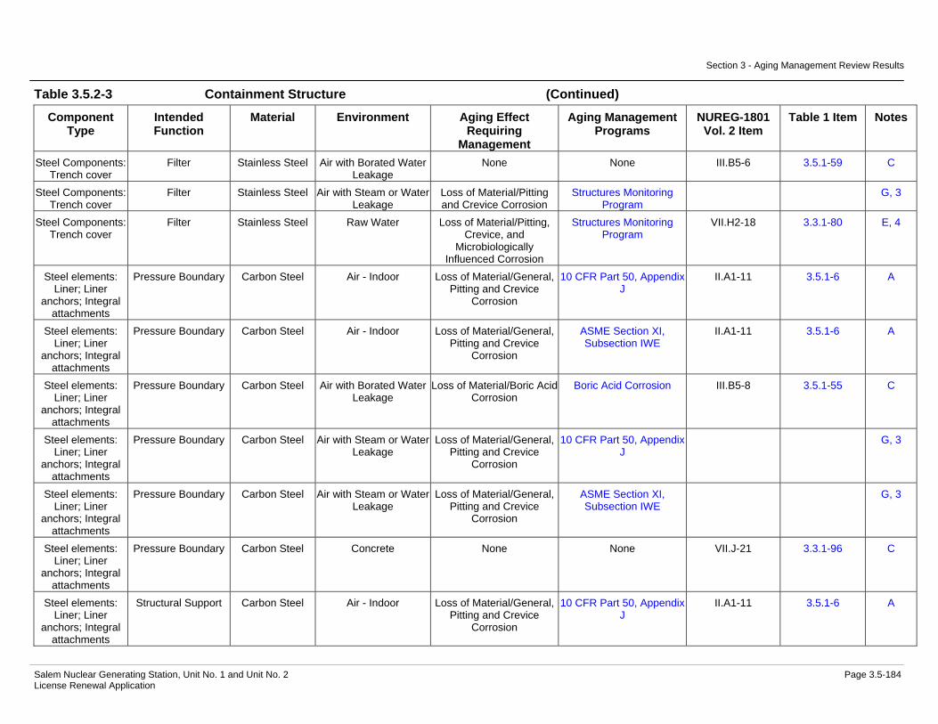
Management Evaluation...............................................................3.5-109 Table 3.5.2-3 Containment Structure Summary of Aging Management
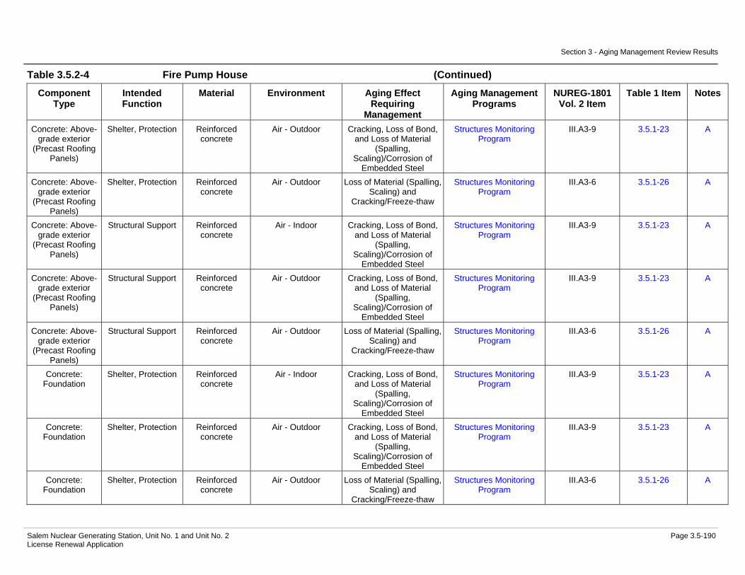
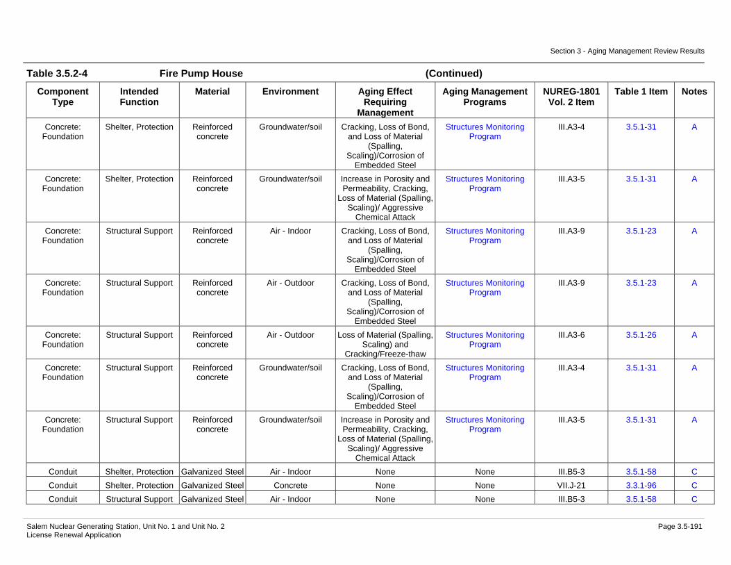
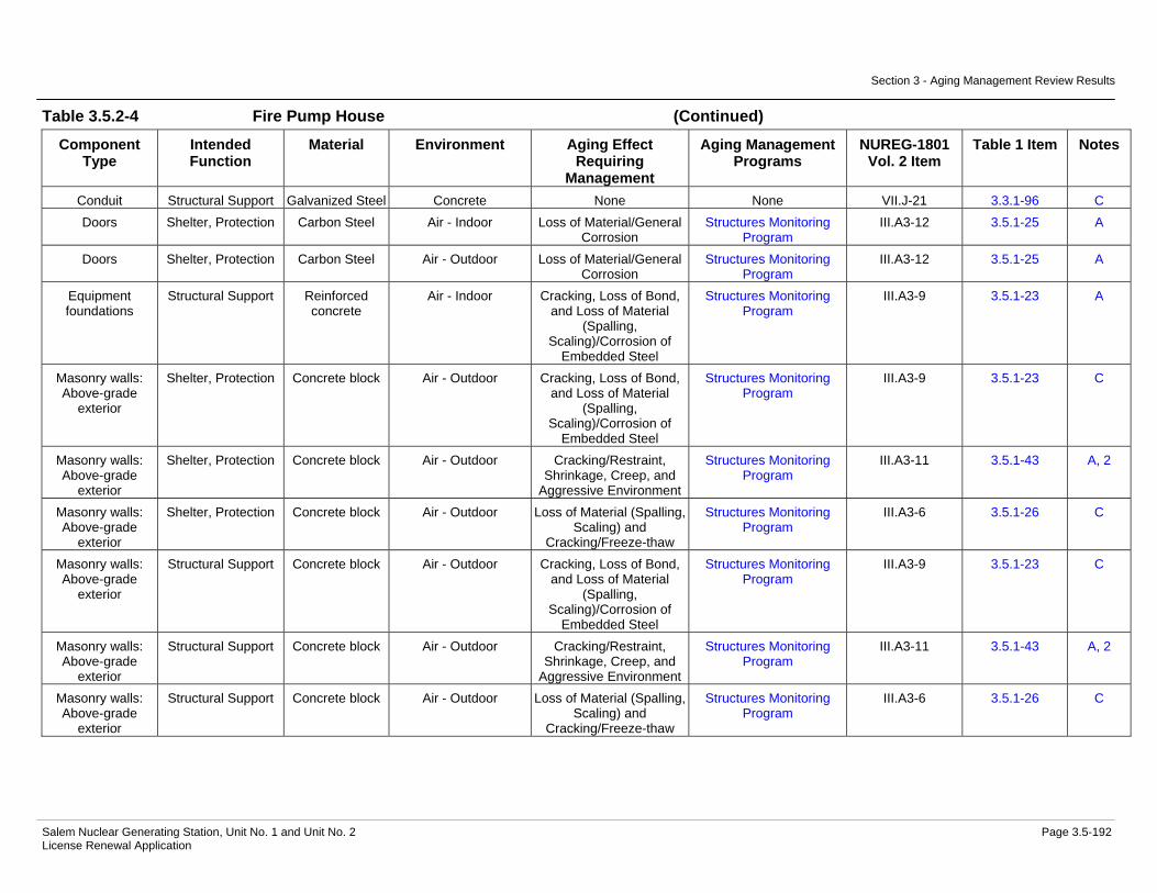
Evaluation.....................................................................................3.5-159 Table 3.5.2-4 Fire Pump House Summary of Aging Management Evaluation ...3.5-189

Table of Contents
Salem Nuclear Generating Station, Unit No. 1 and Unit No. 2 Page xiv License Renewal Application
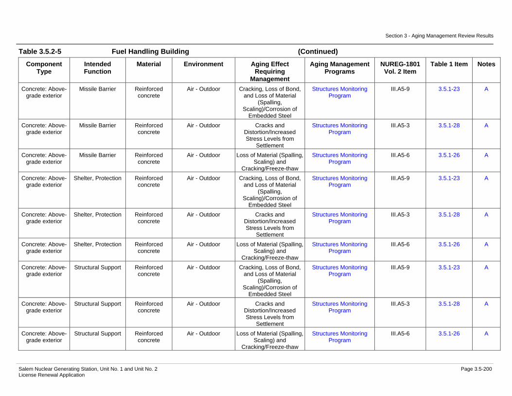
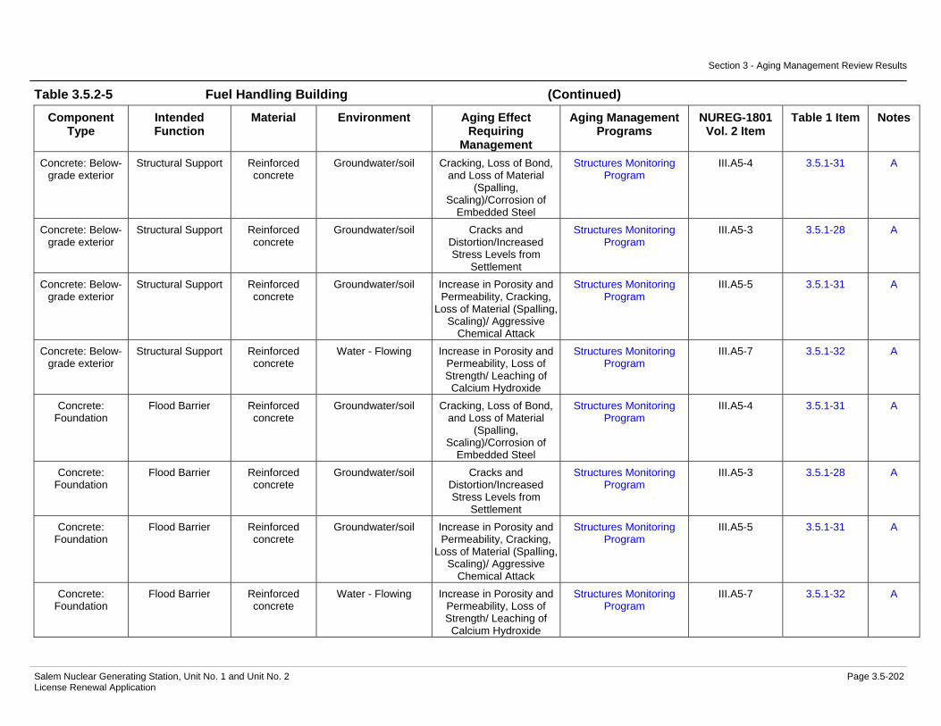
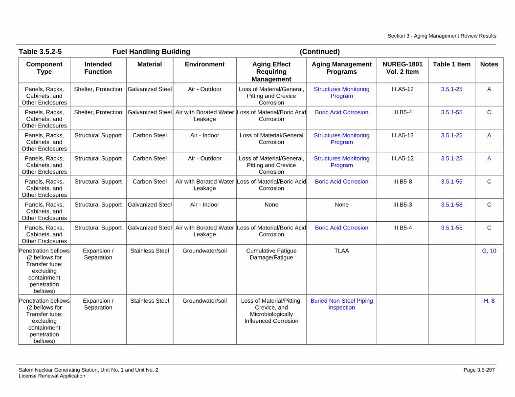
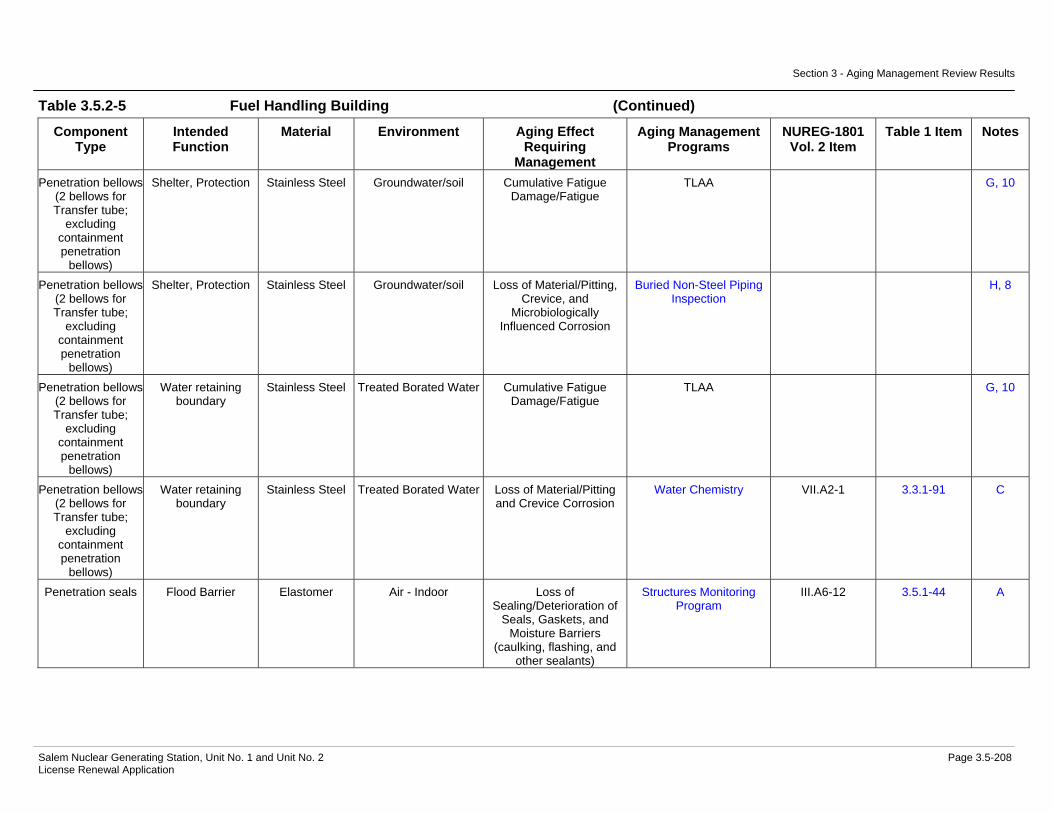
Table 3.5.2-5 Fuel Handling Building Summary of Aging Management Evaluation.....................................................................................3.5-198
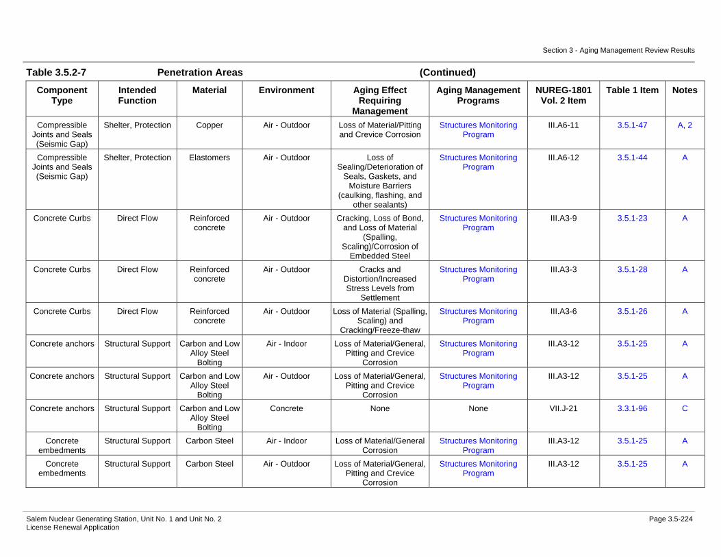
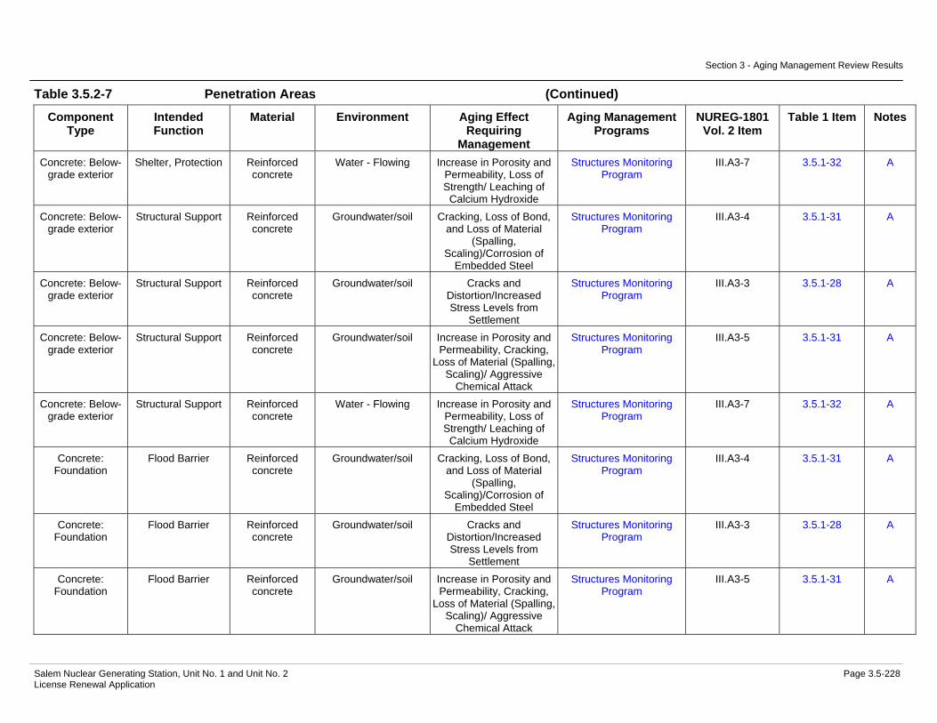
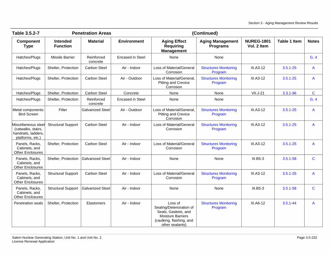
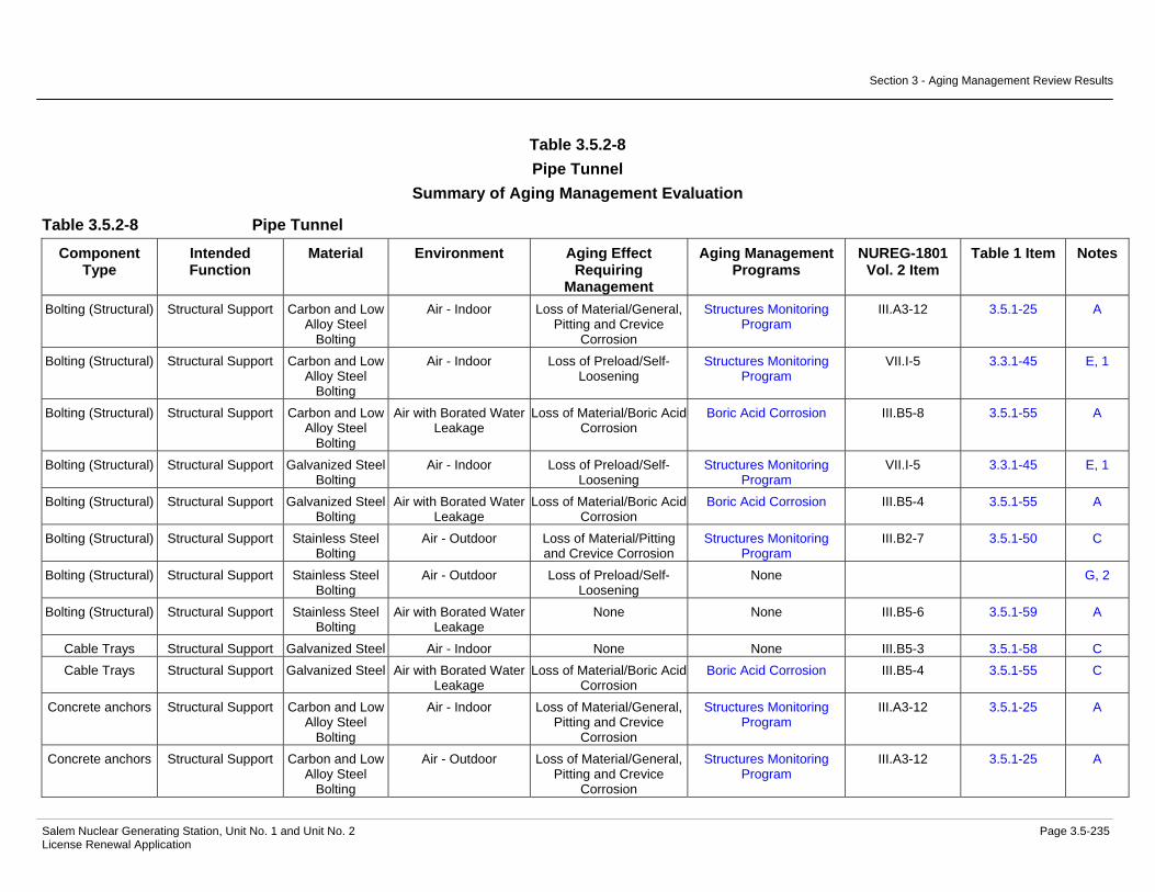
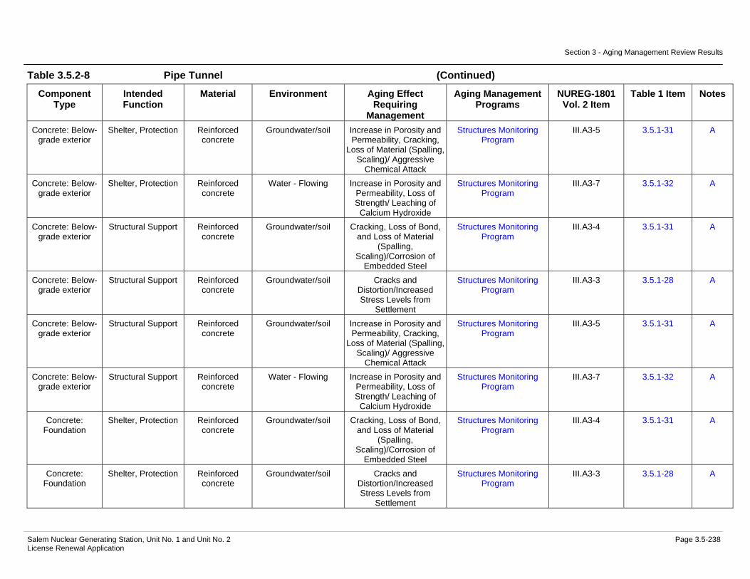
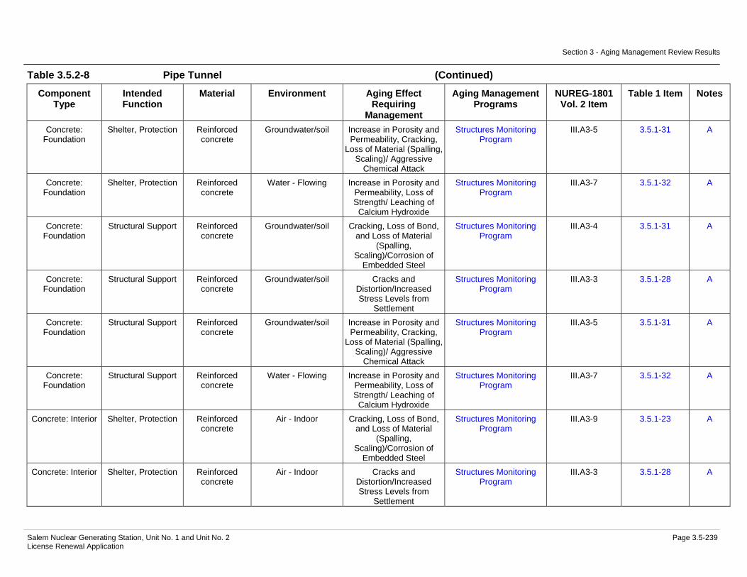
Table 3.5.2-6 Office Buildings Summary of Aging Management Evaluation ......3.5-215 Table 3.5.2-7 Penetration Areas Summary of Aging Management Evaluation...3.5-223 Table 3.5.2-8 Pipe Tunnel Summary of Aging Management Evaluation ............3.5-235 Table 3.5.2-9 Piping and Component Insulation Commodity Group Summary
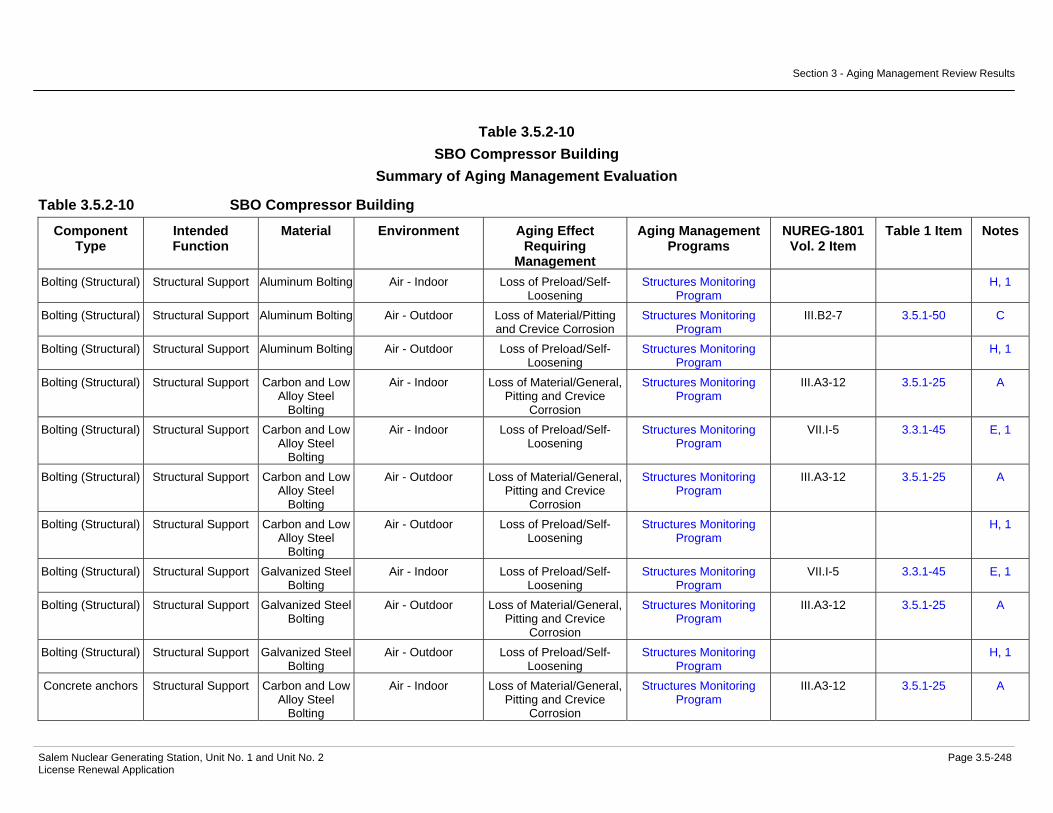
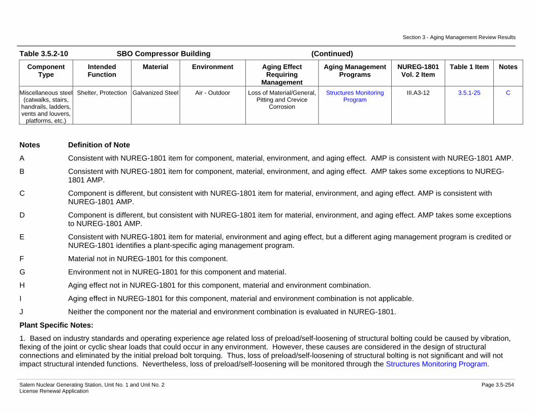
of Aging Management Evaluation.................................................3.5-244 Table 3.5.2-10 SBO Compressor Building Summary of Aging Management
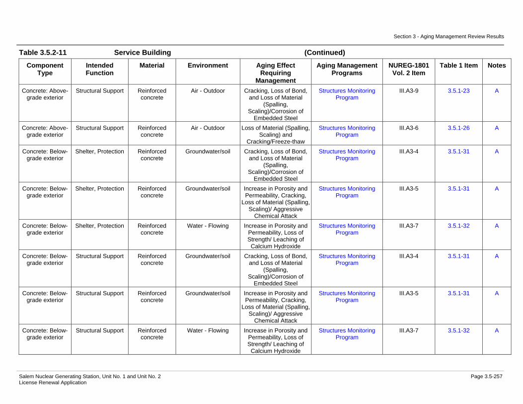
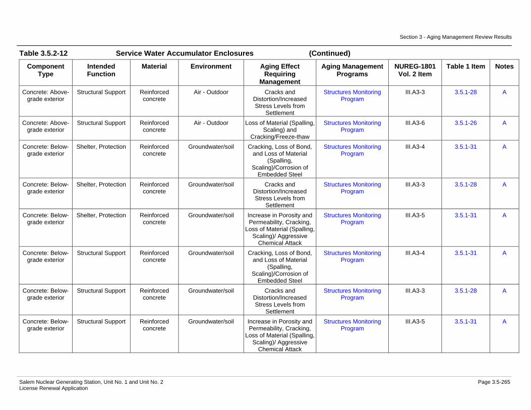
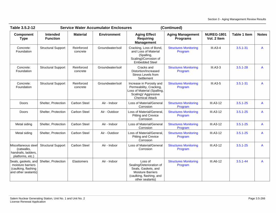
Evaluation.....................................................................................3.5-248 Table 3.5.2-11 Service Building Summary of Aging Management Evaluation......3.5-256 Table 3.5.2-12 Service Water Accumulator Enclosures Summary of Aging
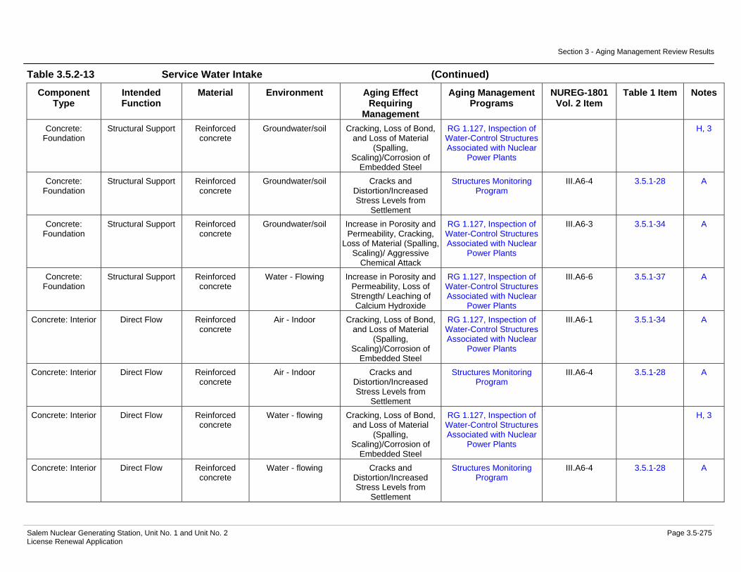
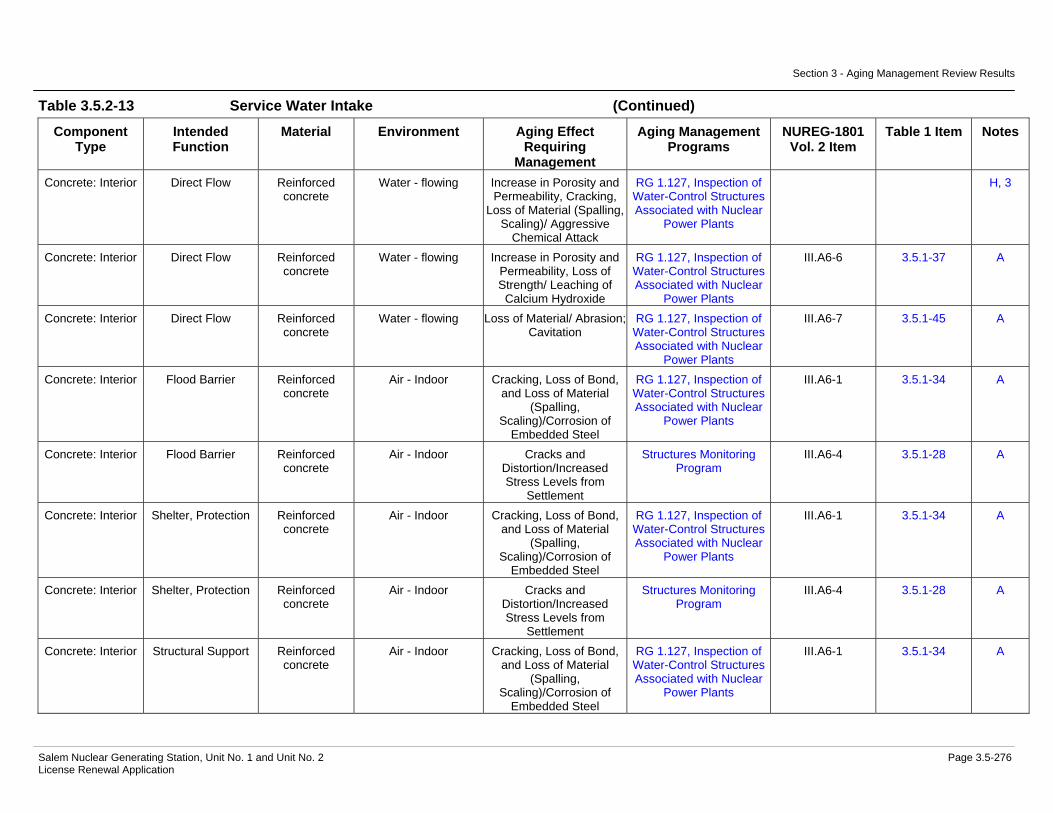
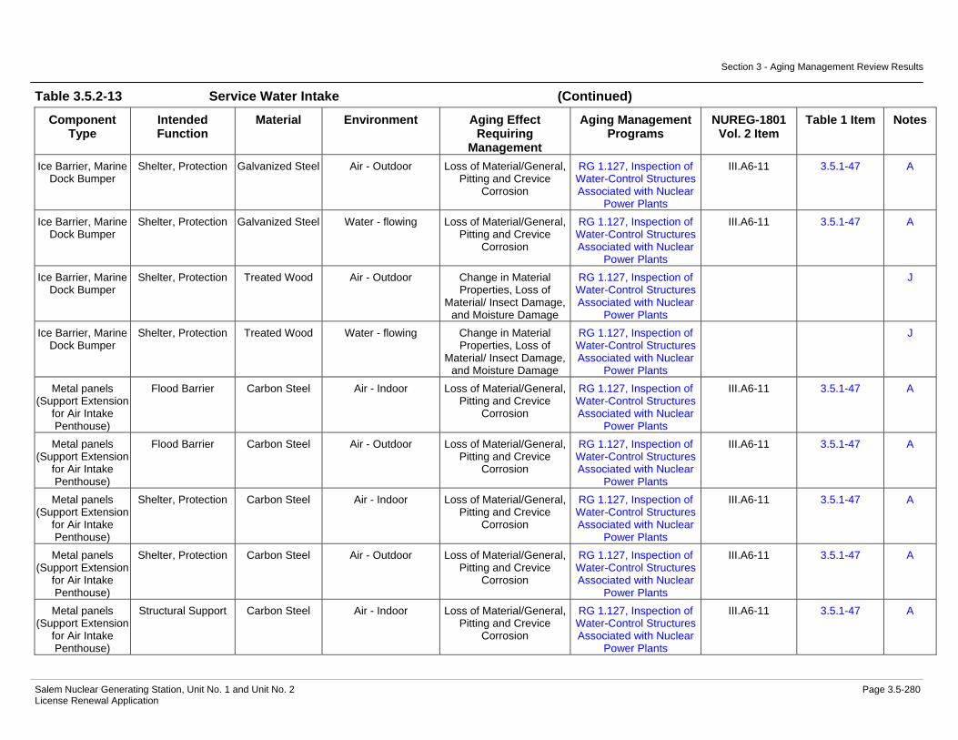
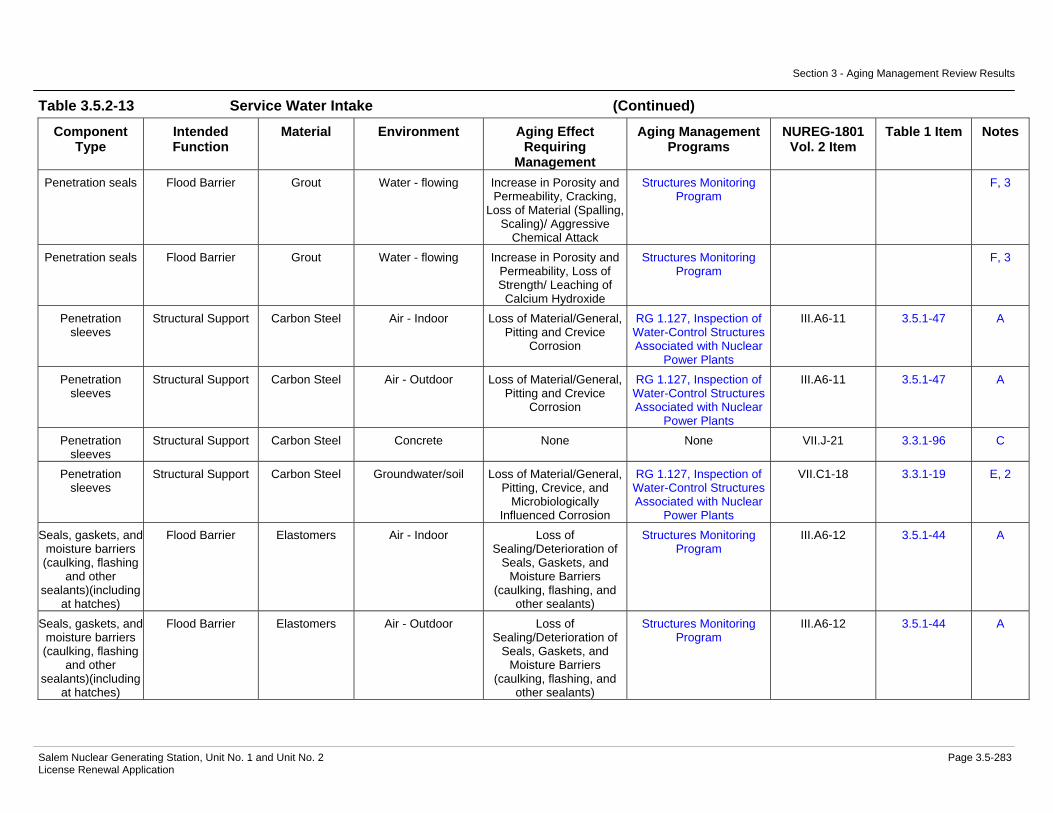
Management Evaluation...............................................................3.5-263 Table 3.5.2-13 Service Water Intake Summary of Aging Management
Evaluation.....................................................................................3.5-269 Table 3.5.2-14 Shoreline Protection and Dike Summary of Aging Management
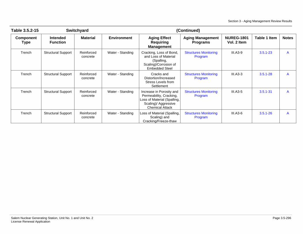
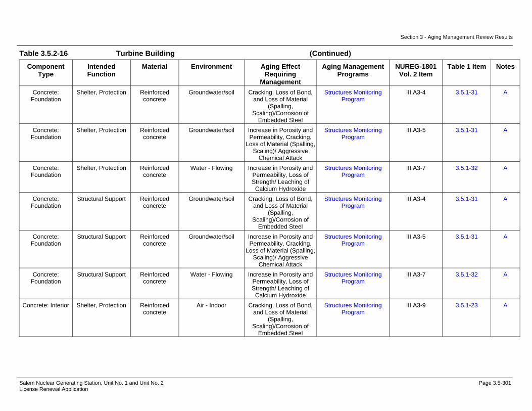
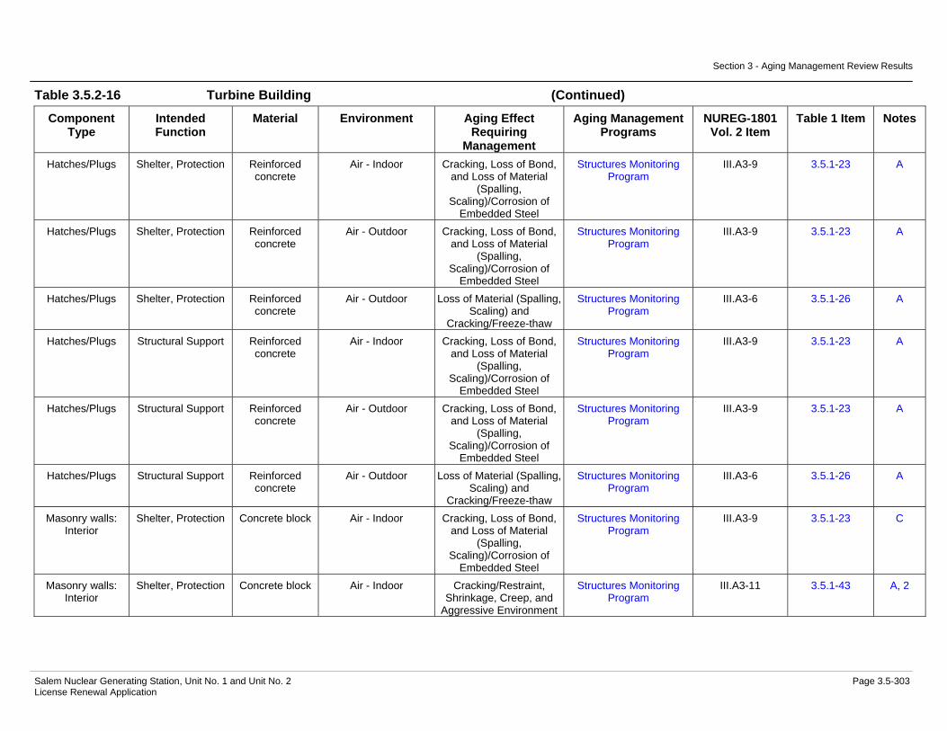
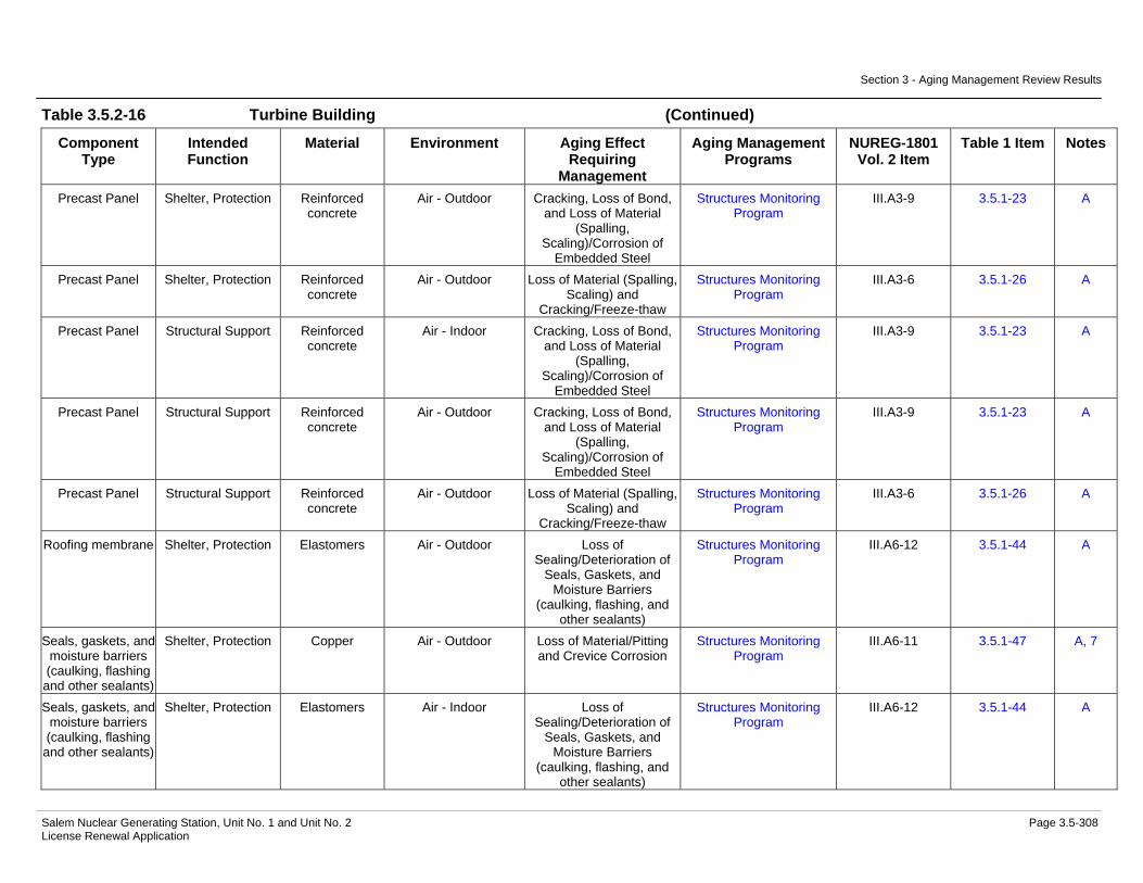
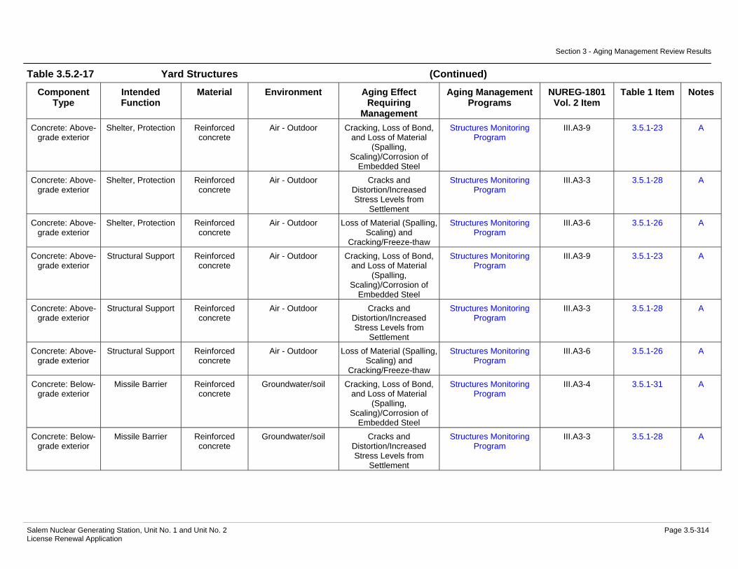
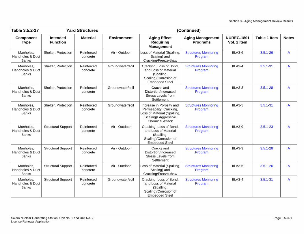
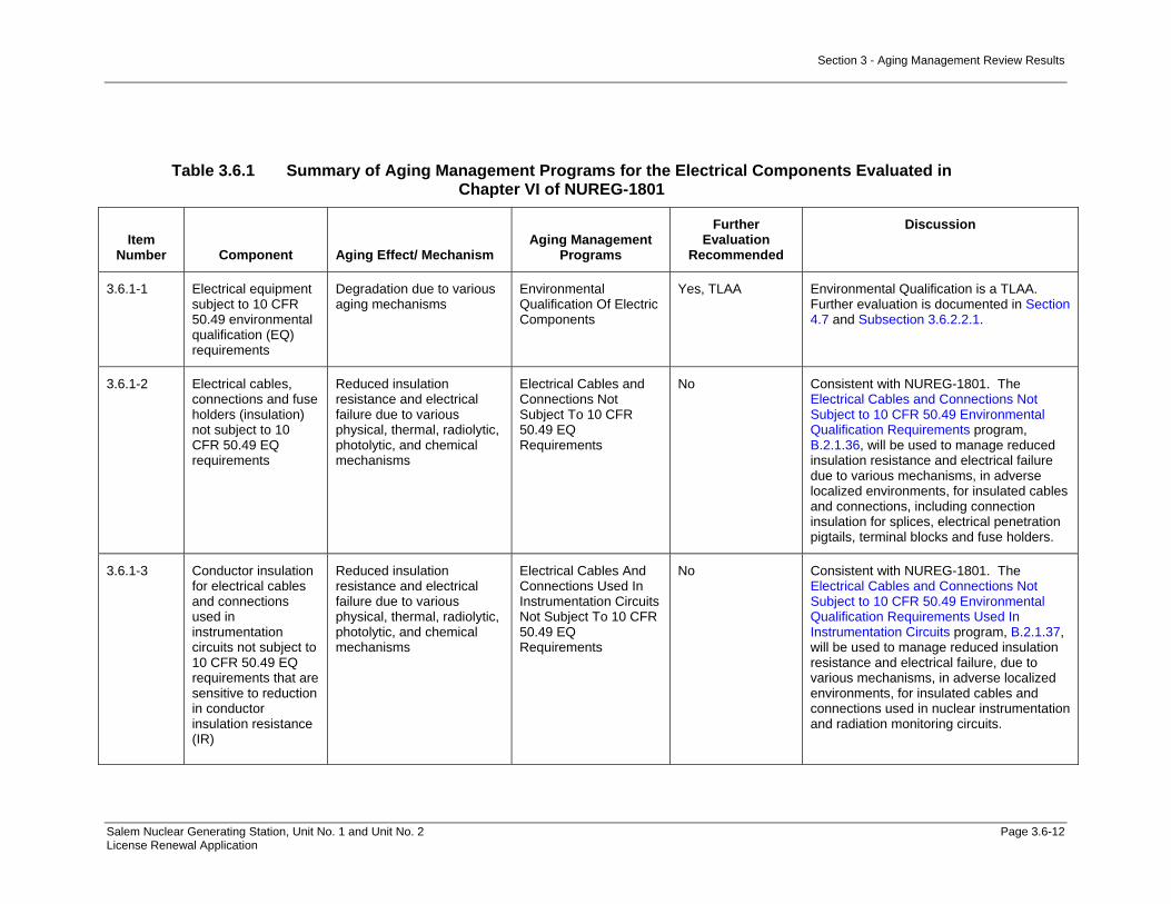
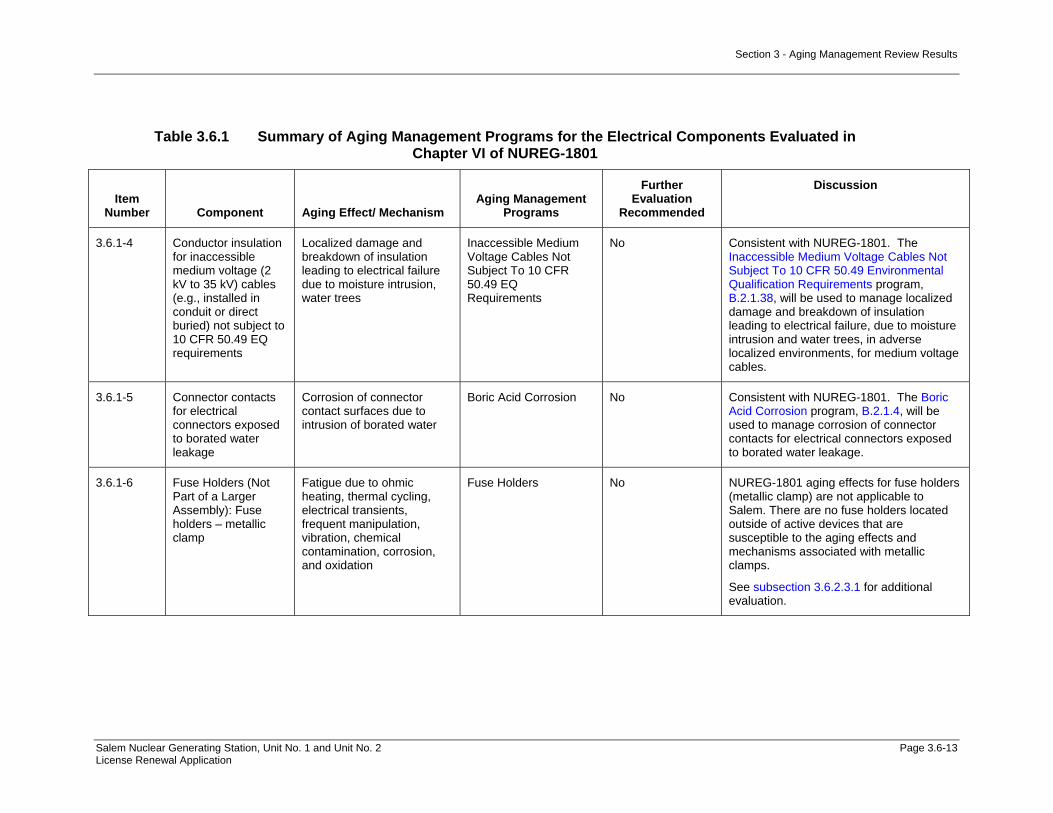
Evaluation.....................................................................................3.5-286 Table 3.5.2-15 Switchyard Summary of Aging Management Evaluation..............3.5-289 Table 3.5.2-16 Turbine Building Summary of Aging Management Evaluation .....3.5-298 Table 3.5.2-17 Yard Structures Summary of Aging Management Evaluation ......3.5-312 Table 3.6.1 Summary of Aging Management Programs for the Electrical
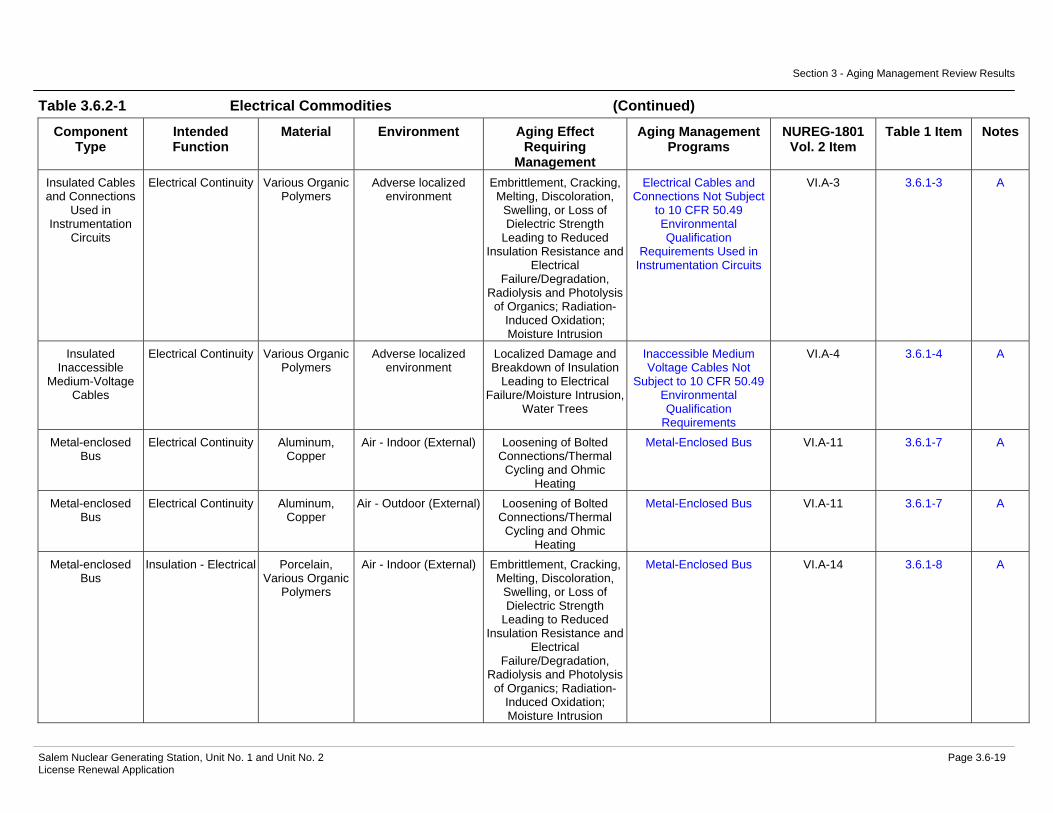
Components Evaluated in Chapter VI of NUREG-1801 .......................3.6-12 Table 3.6.2-1 Electrical Commodities-Summary of Aging Management
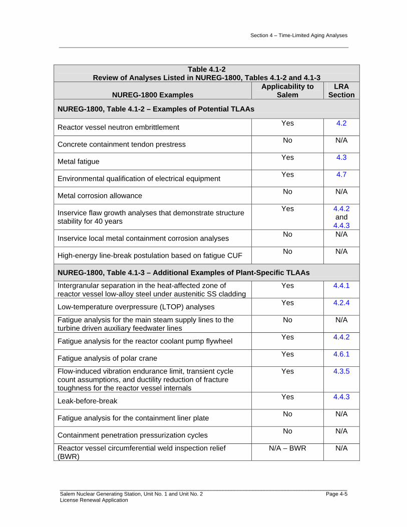
Evaluation.......................................................................................3.6-17 Table 4.1-1 Time-Limited Aging Analyses Applicable to Salem ...................................4-4 Table 4.1-2 Review of Analyses Listed in NUREG-1800, Tables 4.1-2 and 4.1-3 .......4-5 Table 4.2.1-1 50 EFPY Surface Fluence Projections for Beltline and Extended
Beltline Materials for Salem Unit 1 ......................................................4-9 Table 4.2.1-2 50 EFPY Surface Fluence Projections for Beltline and Extended
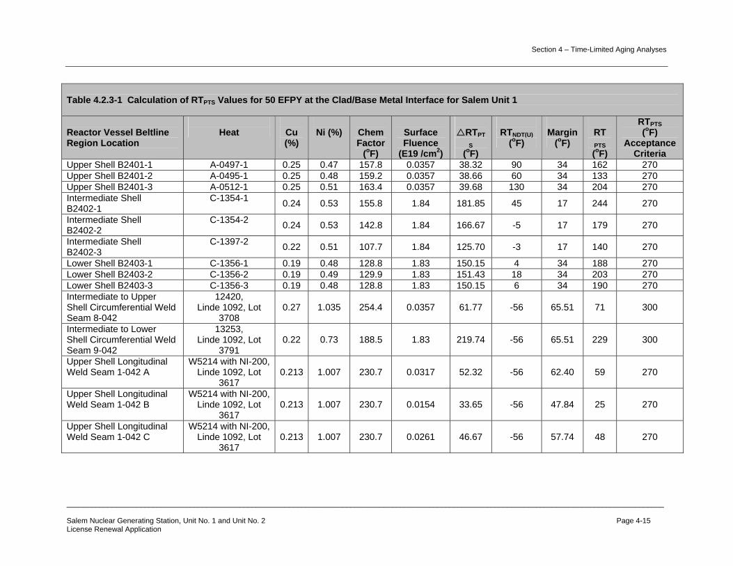
Beltline Materials for Salem Unit 2 ....................................................4-10 Table 4.2.2-1 Predicted USE Values at 50 EFPY for Salem Unit 1 .........................4-12 Table 4.2.2-2 Predicted USE Values at 50 EFPY for Salem Unit 2 .........................4-13 Table 4.2.3-1 Calculation of RTPTS Values for 50 EFPY at the Clad/Base Metal
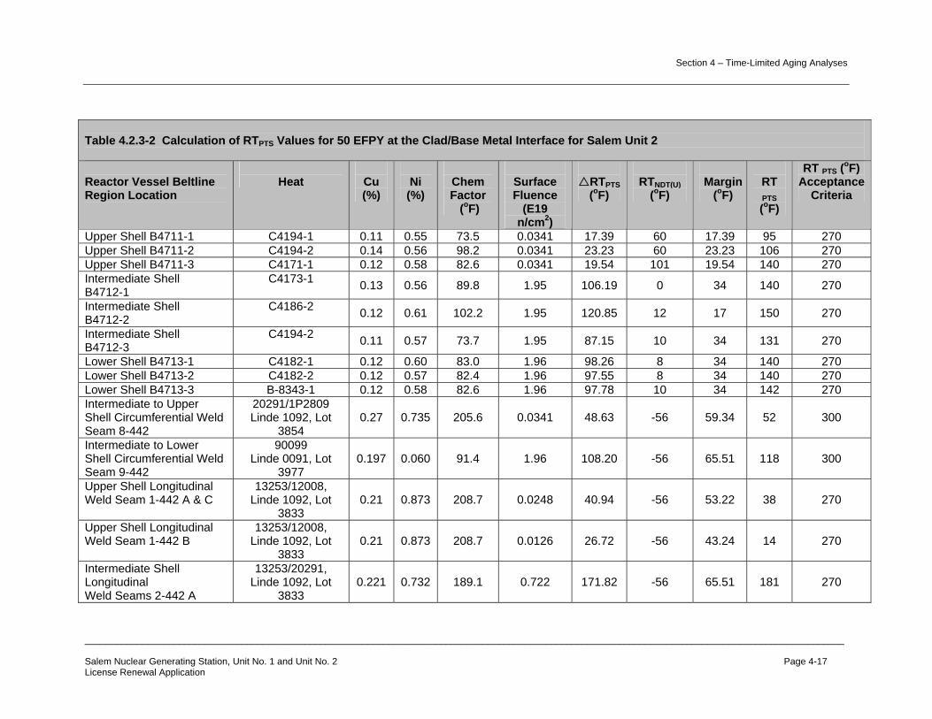
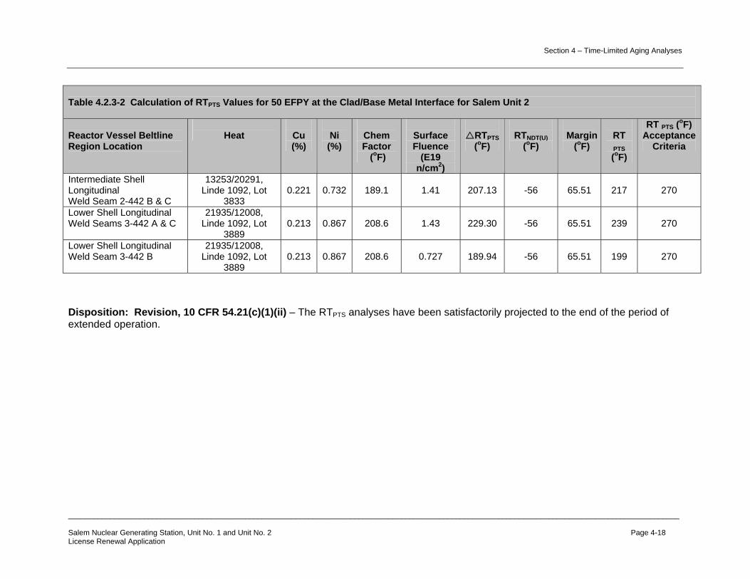
Interface for Salem Unit 1..................................................................4-15 Table 4.2.3-2 Calculation of RTPTS Values for 50 EFPY at the Clad/Base Metal
Interface for Salem Unit 2..................................................................4-17 Table 4.2.4-1 Summary of the Limiting ART Values used in Generation of the
Salem Unit 1 Reactor Vessel Heatup and Cooldown Curves............4-20 Table 4.2.4-2 Summary of the Limiting ART Values used in Generation of the
Salem Unit 2 Reactor Vessel Heatup and Cooldown Curves............4-20
Table of Contents
Salem Nuclear Generating Station, Unit No. 1 and Unit No. 2 Page xv License Renewal Application
Table 4.2.4-3 LTOP Single Setpoints and Arming/Enable Temperature for Salem Units 1 and 2 ..........................................................................4-21
Table 4.3.1-1 Original Design Codes for NSSS Components at Salem Units 1
and 2..................................................................................................4-23 Table 4.3.1-2 Design Transient Cycles for NSSS Class A and Class 1
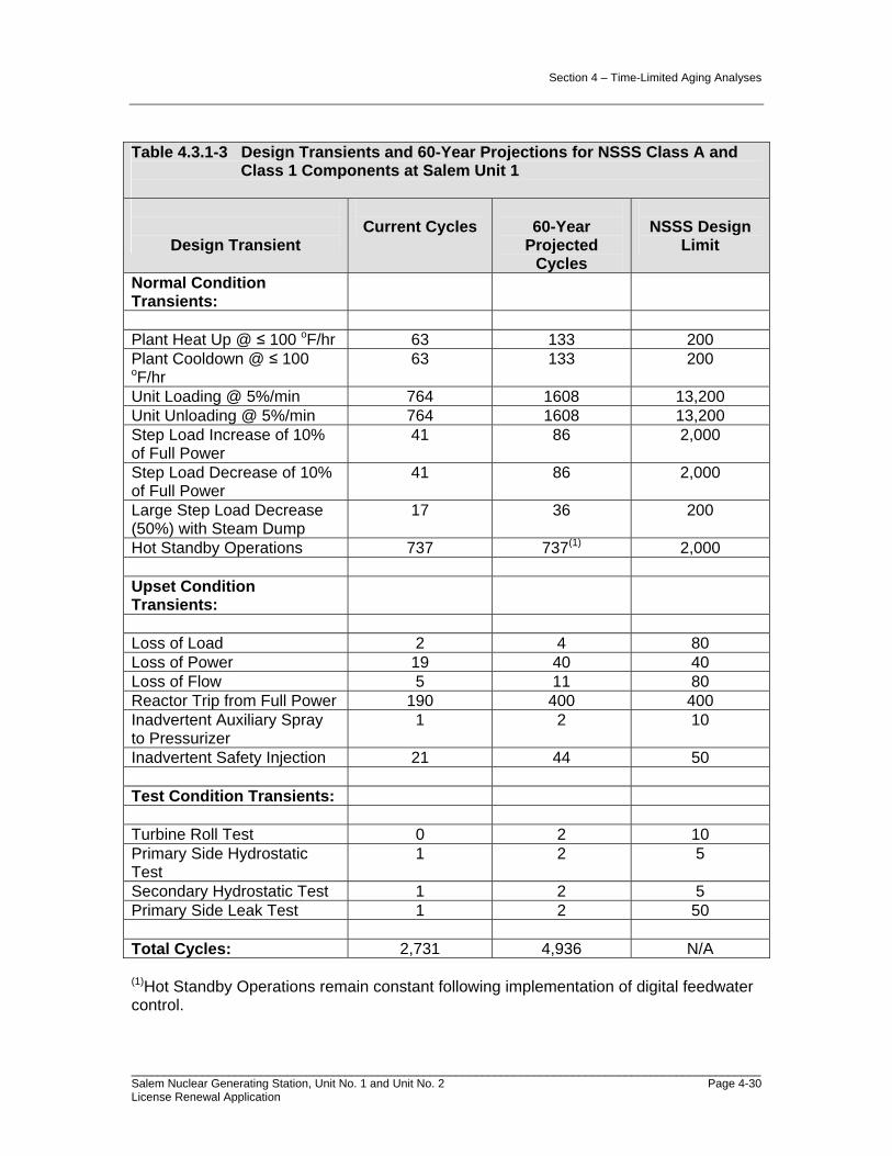
Components at Salem Units 1 and 2.................................................4-24 Table 4.3.1-3 Design Transients and 60-Year Projections for NSSS Class A
and Class 1 Components at Salem Unit 1.........................................4-30 Table 4.3.1-4 Design Transients and 60 Year Projections for NSSS Class A
and Class 1 Components at Salem Unit 2.........................................4-31 Table 4.3.2-1 Salem 60-Year Projections of Transients Applicable to the
Pressurizer Safety Valve Fatigue Analyses.......................................4-32 Table 4.3.2-2 Salem 60-Year Projections of Transients Applicable to the
Pressurizer Pilot-Operated Relief Valve Fatigue Analyses................4-33 Table 4.3.4-1 Updated Design Codes for Select Salem Units 1 and 2 Piping
Systems ............................................................................................4-36 Table 4.3.6-1 Salem 60-Year Projections of Transients Applicable to the Spent
Fuel Pool Bottom Plates Fatigue Analyses .......................................4-41 Table 4.3.6-2 Salem Units 1 and 2 60-Year Projections of Transients
Applicable to the Spent Fuel Pool Bottom Plates Fuel Rack Pedestal Fatigue Analyses ................................................................4-42
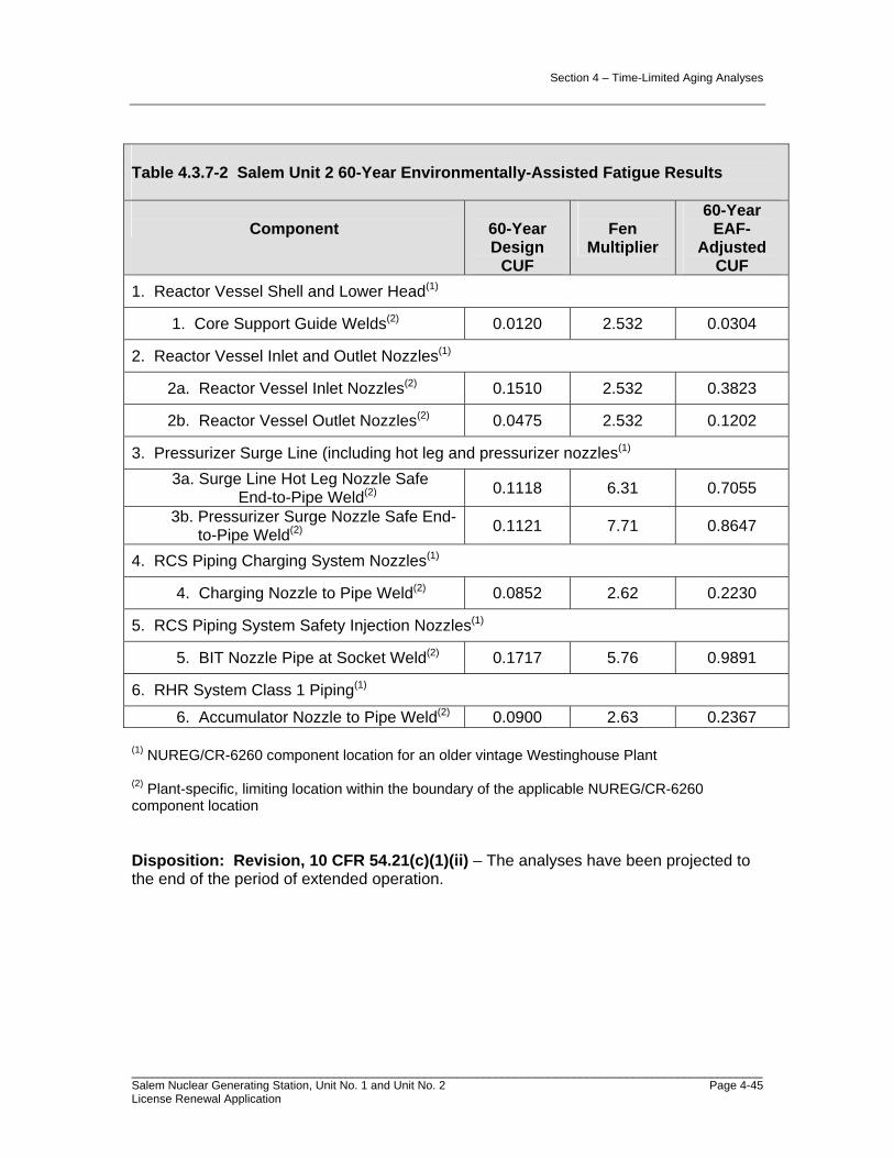
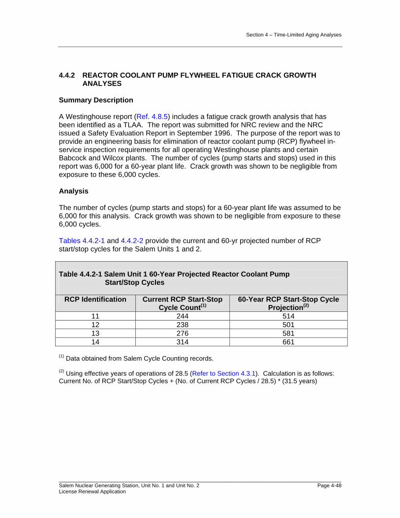
Table 4.3.7-1 Salem Unit 1 60-Year Environmentally-Assisted Fatigue Results .....4-44 Table 4.3.7-2 Salem Unit 2 60-Year Environmentally-Assisted Fatigue Results .....4-45 Table 4.4.2-1 Salem Unit 1 60-Year Projected Reactor Coolant Pump
Start/Stop Cycles .............................................................................4-48 Table 4.4.2-2 Salem Unit 2 60-Year Projected Reactor Coolant Pump
Start/Stop Cycles .............................................................................4-49 Table 4.4.5-1 Salem Unit 1 60-Year Projection of Transients Applicable to the
Volume Control Tank Flaw Growth Analysis ...................................4-51 List of Figures Figure 2.1-1 Salem Scoping and Screening Flowchart.........................................2.1-3 Figure 2.1-2 Salem Offsite Power for SBO .........................................................2.1-13
Section 1 - Administrative Information
Salem Nuclear Generating Station, Unit No. 1 and Unit No. 2 Page 1-1 License Renewal Application
1.0 ADMINISTRATIVE INFORMATION
1.1 GENERAL INFORMATION - 10 CFR 54.19
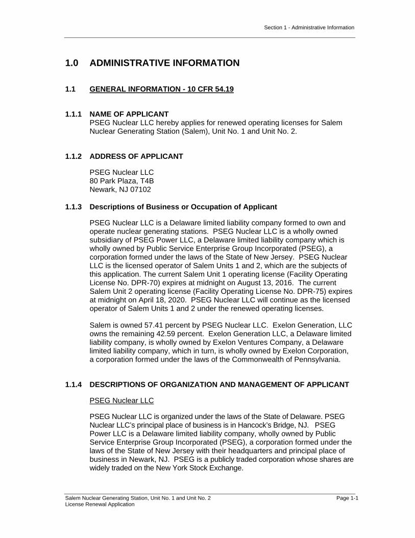
1.1.1 NAME OF APPLICANT PSEG Nuclear LLC hereby applies for renewed operating licenses for Salem Nuclear Generating Station (Salem), Unit No. 1 and Unit No. 2.
1.1.2 ADDRESS OF APPLICANT
PSEG Nuclear LLC 80 Park Plaza, T4B Newark, NJ 07102
1.1.3 Descriptions of Business or Occupation of Applicant
PSEG Nuclear LLC is a Delaware limited liability company formed to own and operate nuclear generating stations. PSEG Nuclear LLC is a wholly owned subsidiary of PSEG Power LLC, a Delaware limited liability company which is wholly owned by Public Service Enterprise Group Incorporated (PSEG), a corporation formed under the laws of the State of New Jersey. PSEG Nuclear LLC is the licensed operator of Salem Units 1 and 2, which are the subjects of this application. The current Salem Unit 1 operating license (Facility Operating License No. DPR-70) expires at midnight on August 13, 2016. The current Salem Unit 2 operating license (Facility Operating License No. DPR-75) expires at midnight on April 18, 2020. PSEG Nuclear LLC will continue as the licensed operator of Salem Units 1 and 2 under the renewed operating licenses.
Salem is owned 57.41 percent by PSEG Nuclear LLC. Exelon Generation, LLC owns the remaining 42.59 percent. Exelon Generation LLC, a Delaware limited liability company, is wholly owned by Exelon Ventures Company, a Delaware limited liability company, which in turn, is wholly owned by Exelon Corporation, a corporation formed under the laws of the Commonwealth of Pennsylvania.
1.1.4 DESCRIPTIONS OF ORGANIZATION AND MANAGEMENT OF APPLICANT
PSEG Nuclear LLC
PSEG Nuclear LLC is organized under the laws of the State of Delaware. PSEG Nuclear LLC’s principal place of business is in Hancock’s Bridge, NJ. PSEG Power LLC is a Delaware limited liability company, wholly owned by Public Service Enterprise Group Incorporated (PSEG), a corporation formed under the laws of the State of New Jersey with their headquarters and principal place of business in Newark, NJ. PSEG is a publicly traded corporation whose shares are widely traded on the New York Stock Exchange.
Section 1 - Administrative Information
Salem Nuclear Generating Station, Unit No. 1 and Unit No. 2 Page 1-2 License Renewal Application
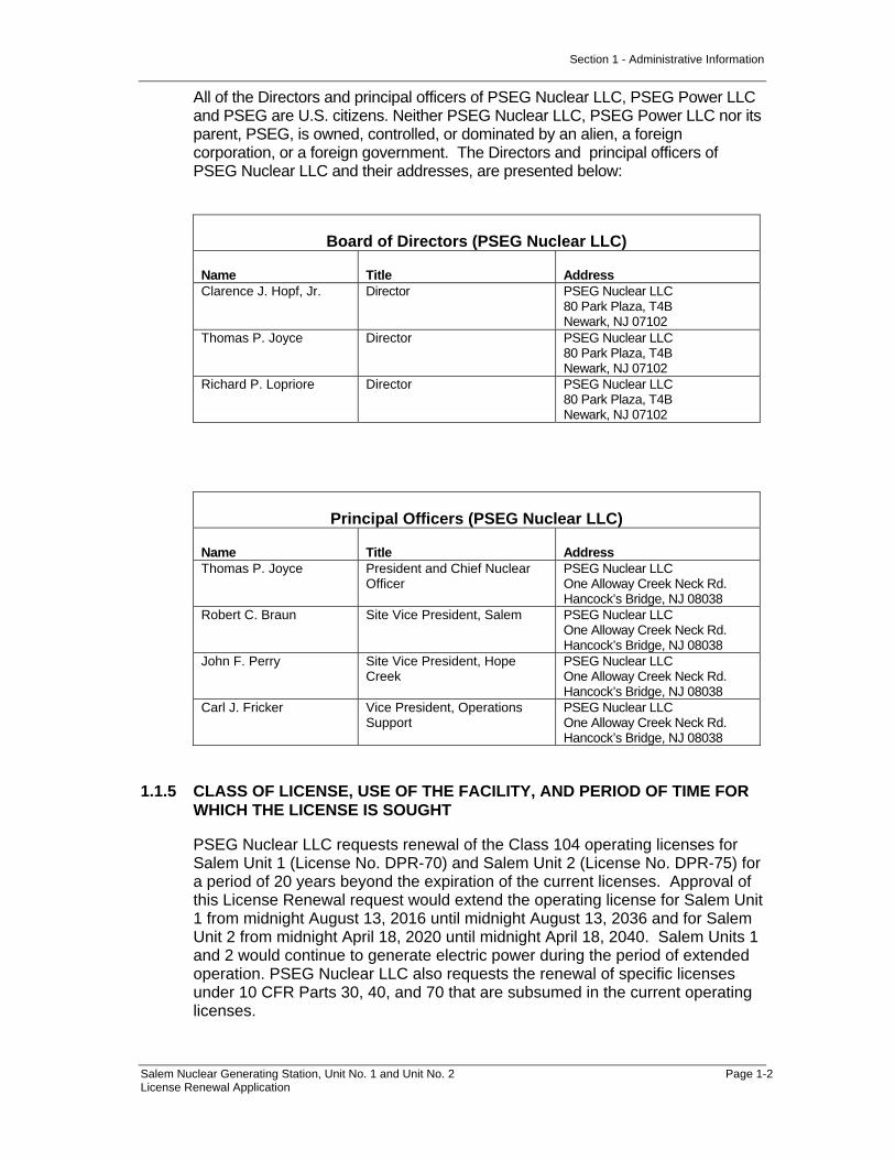
All of the Directors and principal officers of PSEG Nuclear LLC, PSEG Power LLC and PSEG are U.S. citizens. Neither PSEG Nuclear LLC, PSEG Power LLC nor its parent, PSEG, is owned, controlled, or dominated by an alien, a foreign corporation, or a foreign government. The Directors and principal officers of PSEG Nuclear LLC and their addresses, are presented below:
Board of Directors (PSEG Nuclear LLC)
Name Title Address Clarence J. Hopf, Jr. Director PSEG Nuclear LLC
80 Park Plaza, T4B Newark, NJ 07102
Thomas P. Joyce Director PSEG Nuclear LLC 80 Park Plaza, T4B Newark, NJ 07102
Richard P. Lopriore Director PSEG Nuclear LLC 80 Park Plaza, T4B Newark, NJ 07102
Principal Officers (PSEG Nuclear LLC)
Name Title Address Thomas P. Joyce President and Chief Nuclear
Officer PSEG Nuclear LLC One Alloway Creek Neck Rd. Hancock’s Bridge, NJ 08038
Robert C. Braun Site Vice President, Salem PSEG Nuclear LLC One Alloway Creek Neck Rd. Hancock’s Bridge, NJ 08038
John F. Perry Site Vice President, Hope Creek
PSEG Nuclear LLC One Alloway Creek Neck Rd. Hancock’s Bridge, NJ 08038
Carl J. Fricker Vice President, Operations Support
PSEG Nuclear LLC One Alloway Creek Neck Rd. Hancock’s Bridge, NJ 08038
1.1.5 CLASS OF LICENSE, USE OF THE FACILITY, AND PERIOD OF TIME FOR WHICH THE LICENSE IS SOUGHT
PSEG Nuclear LLC requests renewal of the Class 104 operating licenses for Salem Unit 1 (License No. DPR-70) and Salem Unit 2 (License No. DPR-75) for a period of 20 years beyond the expiration of the current licenses. Approval of this License Renewal request would extend the operating license for Salem Unit 1 from midnight August 13, 2016 until midnight August 13, 2036 and for Salem Unit 2 from midnight April 18, 2020 until midnight April 18, 2040. Salem Units 1 and 2 would continue to generate electric power during the period of extended operation. PSEG Nuclear LLC also requests the renewal of specific licenses under 10 CFR Parts 30, 40, and 70 that are subsumed in the current operating licenses.

Section 1 - Administrative Information
Salem Nuclear Generating Station, Unit No. 1 and Unit No. 2 Page 1-3 License Renewal Application
1.1.6 EARLIEST AND LATEST DATES FOR ALTERATIONS, IF PROPOSED
No plant alterations or modifications have been identified as necessary in connection with this application.
1.1.7 RESTRICTED DATA
With regard to the requirements of 10 CFR 54.17(f), this application does not contain any “Restricted Data,” as that term is defined in the Atomic Energy Act of 1954, as amended, or other defense information, and it is not expected that any such information will become involved in these licensed activities.
In accordance with the requirements of 10 CFR 54.17(g), the applicant will not permit any individual to have access to, or any facility to possess restricted data or classified national security information until the individual and/or facility has been approved for such access under the provisions of 10 CFR Parts 25 and/or 95.
1.1.8 REGULATORY AGENCIES PSEG Nuclear LLC recovers the costs incurred from operating Salem in its own wholesale rates. The Federal Energy Regulatory Commission (FERC) regulates the interstate sales of electricity generated at Salem:
Federal Energy Regulatory Commission 888 First St. N.E. Washington, DC 20426
1.1.9 LOCAL NEWS PUBLICATIONS
News publications in circulation near Salem that are considered appropriate to give reasonable notice of the application are as follows:
Today’s Sunbeam 93 Fifth Street Salem, NJ 08079 856-935-1500 Gloucester County Times 309 South Broad Street Woodbury, NJ 08096 856-845-3300 Bridgeton News 100 East Commerce Street Bridgeton, NJ 08302 856-451-1000 The News Journal P.O. Box 15505 Wilmington, DE 19850

Section 1 - Administrative Information
Salem Nuclear Generating Station, Unit No. 1 and Unit No. 2 Page 1-4 License Renewal Application
302-324-2500
1.1.10 Conforming Changes To Standard Indemnity Agreement
10 CFR 54.19(b) requires that “each application must include conforming changes to the standard indemnity agreement, 10 CFR 140.92, Appendix B, to account for the expiration term of the proposed renewed license.” The current indemnity agreements (No. P08-046 for Salem Unit 1 and No. X08-084 for Salem Unit 2) state in Article VII that the agreement shall terminate at the time of expiration of that license specified in Item 3 of the Attachment to the agreement, which is the last to expire; provided that, except as may otherwise be provided in applicable regulations or orders of the Commission, the term of this agreement shall not terminate until all the radioactive material has been removed from the location and transportation of the radioactive material from the location has ended as defined in subparagraph 5(b), Article I. Item 3 of the Attachment to the indemnity agreement includes license numbers, DPR-70 and DPR-75. Applicant requests that any necessary conforming changes be made to Article VII and Item 3 of the Attachment, and any other sections of the indemnity agreement as appropriate to ensure that the indemnity agreement continues to apply during both the terms of the current licenses and the terms of the renewed licenses. Applicant understands that no changes may be necessary for this purpose if the current license numbers are retained.

Section 1 - Administrative Information
Salem Nuclear Generating Station, Unit No. 1 and Unit No. 2 Page 1-5 License Renewal Application
1.2 GENERAL LICENSE INFORMATION
1.2.1 APPLICATION UPDATES, RENEWED LICENSES, AND RENEWAL TERM OPERATION
In accordance with 10 CFR 54.21(b), during NRC review of this application, an annual update to the application to reflect any change to the current licensing basis that materially affects the contents of the license renewal application will be provided.
In accordance with 10 CFR 54.21(d), PSEG Nuclear LLC will maintain a summary list in the Salem Updated Final Safety Analysis Report (UFSAR) of activities that are required to manage the effects of aging for the systems, structures, or components in the scope of license renewal during the period of extended operation and summaries of the time-limited aging analyses evaluations.
1.2.2 CONTACT INFORMATION
Any notices, questions, or correspondence in connection with this filing should be directed to:
C. Fricker Vice President - Operations Support PSEG Nuclear LLC One Alloway Creek Neck Road Hancock’s Bridge, NJ 08038
with copies to: C. Neely Director, Regulatory Affairs PSEG Nuclear LLC One Alloway Creek Neck Road Hancock’s Bridge, NJ 08038 A. Fakhar Manager, License Renewal PSEG Nuclear LLC One Alloway Creek Neck Road Hancock’s Bridge, NJ 08038
M. Gallagher Vice President License Renewal Projects Exelon Nuclear LLC 200 Exelon Way Kennett Square, PA 19348

Section 1 - Administrative Information
Salem Nuclear Generating Station, Unit No. 1 and Unit No. 2 Page 1-6 License Renewal Application
1.3 PURPOSE
This document provides information required by 10 CFR Part 54 to support the application for renewed licenses for Salem Units 1 and 2. The application contains technical information required by 10 CFR 54.21 and environmental information required by 10 CFR 54.23. The information contained herein is intended to provide the NRC with an adequate basis to make the findings required by 10 CFR 54.29.
1.4 DESCRIPTION OF THE PLANT
Salem is a two-unit facility located at the southern end of Artificial Island in Lower Alloways Creek Township, Salem County, New Jersey. Philadelphia is approximately 64 km (40 mi) northeast and Salem, New Jersey, is 13 km (8 mi) northeast of the site.
Salem occupies about 89 hectares (220 acres) of approximately 300 hectares (740 acres) owned by PSEG Nuclear LLC on Artificial Island. The Hope Creek Generating Station (Hope Creek) is also located within this 300-hectare (740-acre) parcel.
The nuclear steam supply systems for Salem are pressurized water reactors that were designed and supplied by Westinghouse. Salem Units 1 and 2 were initially licensed to operate at a rated power level of 3,411 MWt. License Amendment Nos. 243 (Salem Unit 1) and 224 (Salem Unit 2), dated 5/25/2001, authorized a 1.4 percent increase in the licensed rated power level to 3,459 MWt.
Also located on Artificial Island is Hope Creek, which is also owned by PSEG Nuclear LLC. There are no Hope Creek systems, structures, or components (SSCs) that are relied upon for the operation of Salem. There are interconnections between the Salem and Hope Creek fire protection systems (Section 2.3.3.10).

Section 1 - Administrative Information
Salem Nuclear Generating Station, Unit No. 1 and Unit No. 2 Page 1-7 License Renewal Application
1.5 APPLICATION STRUCTURE
This license renewal application is structured in accordance with Regulatory Guide 1.188, “Standard Format and Content for Applications to Renew Nuclear Plant Operating Licenses,” and NEI 95-10, "Industry Guideline for Implementing the Requirements of 10 CFR Part 54 - The License Renewal Rule”. In addition, Section 3, Aging Management Review Results and Appendix B, Aging Management Programs, are structured to address the guidance provided in NUREG-1800, “Standard Review Plan for Review of License Renewal Applications for Nuclear Power Plants”. NUREG-1800 references NUREG-1801, “Generic Aging Lessons Learned (GALL) Report.” NUREG-1801 was used to determine the adequacy of existing aging management programs and which existing programs should be augmented for license renewal. The results of the aging management review, using NUREG-1801, have been documented and are illustrated in table format in Section 3, “Aging Management Review Results,” of this application.
The application is divided into the following major sections:
Section 1 – Administrative Information
This section provides the administrative information required by 10 CFR 54.17 and 10 CFR 54.19. This section describes the plant and states the purpose for this application. Included in this section are the names, addresses, business descriptions, and organization and management descriptions of the applicant, as well as other administrative information. This section also provides an overview of the structure of the application, general references, and a listing of acronyms used throughout the application.
Section 2 – Scoping and Screening Methodology for Identifying Structures and Components Subject to Aging Management Review, and Implementation Results
This section describes and justifies the methods used in the integrated plant assessment to identify those structures and components subject to an aging management review in accordance with the requirements of 10 CFR 54.21(a)(2). These methods consist of: 1) scoping, which identifies the systems, structures, and components that are within the scope of 10 CFR 54.4(a), and 2) screening under 10 CFR 54.21(a)(1), which identifies those in-scope structures and components that perform their intended function without moving parts or a change in configuration or properties, and that are not subject to replacement based on a qualified life or specified time period. Additionally, the results for systems and structures are described in this section. Scoping results are presented in Section 2.2, "Plant Level Scoping Results." Screening results are presented in Sections 2.3, 2.4, and 2.5.
The screening results consist of lists of components, component groups, and structures that require aging management review. Brief descriptions of mechanical systems and structures within the scope of license renewal are provided as background information. Mechanical system and structure intended functions are provided for in-scope systems and structures. For each

Section 1 - Administrative Information
Salem Nuclear Generating Station, Unit No. 1 and Unit No. 2 Page 1-8 License Renewal Application
in-scope system and structure, components requiring an aging management review are identified, associated component intended functions are identified, and appropriate reference to the Section 3 Tables where the aging management review results are provided.
Selected structural and electrical components, such as component supports and electrical cables, were evaluated as commodities. Under the commodity approach, selected structural and electrical component groups were evaluated based upon common environments and materials. Structural and Electrical components requiring an aging management review are presented in Sections 2.4 and 2.5, respectively. Component intended functions and references to the applicable Section 3 Tables are provided.
Section 3 – Aging Management Review Results
10 CFR 54.21(a)(3) requires a demonstration that the effects of aging will be adequately managed so that the intended functions will be maintained consistent with the current licensing basis throughout the period of extended operation. Section 3 presents the results of the aging management reviews. Section 3 is the link between the scoping and screening results provided in Section 2 and the aging management programs provided in Appendix B.
Aging management review results are presented in tabular form, in a format in accordance with NUREG-1800, "Standard Review Plan for Review of License Renewal Applications." For mechanical systems, aging management review results are provided in Sections 3.1 through 3.4 for the Reactor Vessel, Internals, and Reactor Coolant System, Engineered Safety Features, Auxiliary Systems, and Steam and Power Conversion System, respectively. Aging management review results for Containments, Structures, and Component Supports are provided in Section 3.5. Aging management review results for Electrical and Instrumentation and Controls are provided in Section 3.6.
Tables are provided in each of these sections in accordance with NUREG-1800, which provide aging management review results for components, materials, environments, and aging effects which are addressed in NUREG-1801, and information regarding the degree to which the proposed aging management programs are consistent with those recommended in NUREG-1801.
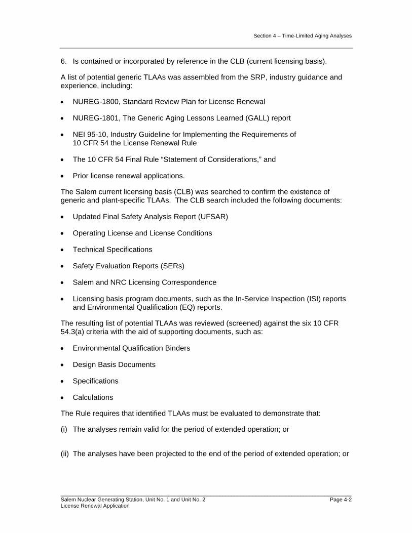
Section 4 – Time-Limited Aging Analyses
Time-limited aging analyses (TLAAs), as defined by 10 CFR 54.3, are listed in this section. This section includes each of the TLAAs identified in the NRC Standard Review Plan for License Renewal Applications and in plant-specific analyses. This section includes a summary of the time-dependent aspects of the analyses. A demonstration is provided to show that the analyses remain valid for the period of extended operation, the analyses have been projected to the end of the period of extended operation, or the effects of aging on the intended function(s) will be adequately managed for the period of extended operation, consistent with 10 CFR 54.21(c)(1)(i)-(iii).
Appendix A –Updated Final Safety Analysis Report Supplement

Section 1 - Administrative Information
Salem Nuclear Generating Station, Unit No. 1 and Unit No. 2 Page 1-9 License Renewal Application
As required by 10 CFR 54.21(d), the Updated Final Safety Analysis Report (UFSAR) supplement contains a summary of activities credited for managing the effects of aging for the period of extended operation. In addition, summary descriptions of time-limited aging analyses evaluations are provided.
Appendix B – Aging Management Programs
Appendix B describes the programs and activities that are credited for managing aging effects for components or structures during the period of extended operation based upon the aging management review results provided in Section 3 and the time-limited aging analyses results provided in Section 4.
Sections B.2.1 and B.3 of Appendix B discuss those programs that are contained in Section XI and Section X of NUREG-1801, respectively. A description of the aging management program is provided and a conclusion based upon the results of an evaluation to each of the ten elements provided in NUREG-1801. In some cases, exceptions and justifications for managing aging are provided for specific NUREG-1801 elements. Additionally, operating experience related to the aging management program is provided.
Section B.2.2 of Appendix B addresses each of the ten program elements for programs that are credited for managing aging that are not evaluated in NUREG-1801.
Appendix C
Appendix C is not used.
Appendix D – Technical Specification Changes
This Appendix satisfies the requirement in 10 CFR 54.22 to identify technical specification changes or additions necessary to manage the effects of aging during the period of extended operation. There were no Technical Specification Changes identified necessary to manage the effects of aging during the period of extended operation.
Appendix E – Environmental Information – Salem Nuclear Generating Station, Unit No. 1 and Unit No. 2
This Appendix satisfies the requirements of 10 CFR 54.23 to provide a supplement to the environmental report that complies with the requirements of subpart A of 10 CFR Part 51 for Salem Units 1 and 2.
Section 1 - Administrative Information
Salem Nuclear Generating Station, Unit No. 1 and Unit No. 2 Page 1-10 License Renewal Application
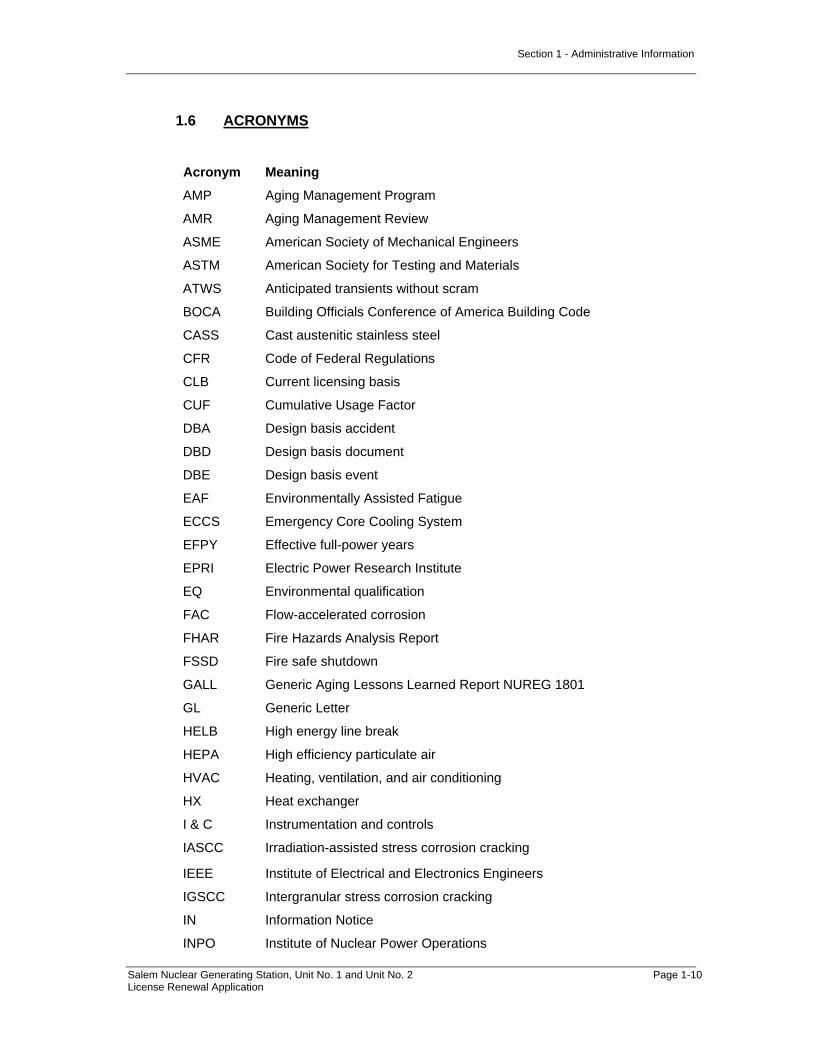
1.6 ACRONYMS
Acronym Meaning
AMP Aging Management Program
AMR Aging Management Review
ASME American Society of Mechanical Engineers
ASTM American Society for Testing and Materials
ATWS Anticipated transients without scram
BOCA Building Officials Conference of America Building Code
CASS Cast austenitic stainless steel
CFR Code of Federal Regulations
CLB Current licensing basis
CUF Cumulative Usage Factor
DBA Design basis accident
DBD Design basis document
DBE Design basis event
EAF Environmentally Assisted Fatigue
ECCS Emergency Core Cooling System
EFPY Effective full-power years
EPRI Electric Power Research Institute
EQ Environmental qualification
FAC Flow-accelerated corrosion
FHAR Fire Hazards Analysis Report
FSSD Fire safe shutdown
GALL Generic Aging Lessons Learned Report NUREG 1801
GL Generic Letter
HELB High energy line break
HEPA High efficiency particulate air
HVAC Heating, ventilation, and air conditioning
HX Heat exchanger
I & C Instrumentation and controls
IASCC Irradiation-assisted stress corrosion cracking
IEEE Institute of Electrical and Electronics Engineers
IGSCC Intergranular stress corrosion cracking
IN Information Notice
INPO Institute of Nuclear Power Operations

Section 1 - Administrative Information
Salem Nuclear Generating Station, Unit No. 1 and Unit No. 2 Page 1-11 License Renewal Application
Acronym Meaning
IPA Integrated plant assessment
ISI Inservice inspection
IST In-service testing
LBB Leak before break
LER Licensee event report
LLRT Local leak rate test
LOCA Loss-of-coolant accident
LRA License renewal application
MCC Motor control center
MIC Microbiologically-influenced corrosion
MOV Motor-operated valve
MSLB Main Steam Line Break
MWt Megawatts thermal
NDE Nondestructive examination
NEI Nuclear Energy Institute
NFPA National Fire Protection Association
NJPDES New Jersey Pollutant Discharge Elimination System
NPSH Net Positive Suction Head
NRC Nuclear Regulatory Commission
OE Operating experience
P&ID Piping and instrumentation diagram
PM Preventive maintenance
PTS Pressurized Thermal Shock
P-T curves Pressure-temperature limit curves
RCPB Reactor coolant pressure boundary
RG Regulatory guide
RTNDT Reference temperature nil-ductility transition
RWST Reactor Water Storage Tank
SCC Stress corrosion cracking
SGS Salem Nuclear Generating Station
SPDS Safety Parameter Display System
SRV Safety relief valve
SSCs Systems, structures, and components
SSE Safe shutdown earthquake
TID Total integrated dose
TLAAs Time-limited aging analyses

Section 1 - Administrative Information
Salem Nuclear Generating Station, Unit No. 1 and Unit No. 2 Page 1-12 License Renewal Application
Acronym Meaning
Salem Salem Nuclear Generating Station
UFSAR Updated Final Safety Analysis Report
UHS Ultimate heat sink
USE Upper-shelf energy

Section 1 - Administrative Information
Salem Nuclear Generating Station, Unit No. 1 and Unit No. 2 Page 1-13 License Renewal Application
1.7 GENERAL REFERENCES
1.7.1 10 CFR 54, “Requirements for Renewal of Operating Licenses for Nuclear Power Plants.”
1.7.2 NEI 95-10, “Industry Guidelines for Implementing the Requirements of 10 CFR Part 54 – The License Renewal Rule,” Revision 6, June 2005.
1.7.3 Regulatory Guide 1.188, “Standard Format and Content for Applications to Renew Nuclear Power Plant Operating Licenses”, Rev 1, September 2005.
1.7.4 NUREG-1800, “Standard Review Plan for Review of License Renewal Applications for Nuclear Power Plants”, United States Nuclear Regulatory Commission, Rev 1, September 2005.
1.7.5 NUREG-1801, “Generic Aging Lessons Learned (GALL) Report,” United States Nuclear Regulatory Commission, Rev 1, September 2005.
1.7.6 10 CFR 50.48, “Fire Protection.”
1.7.7 10 CFR 50.49, “Environmental Qualification of Electric Equipment Important to Safety for Nuclear Power Plants.”
1.7.8 10 CFR 50.62, “Requirements for Reduction of Risk from Anticipated Transients Without Scram (ATWS) Events for Light-Water-Cooled Nuclear Power Plants.”
1.7.9 10 CFR 50.63, “Loss of All Alternating Current Power.”
1.7.10 10 CFR 50.61, “Pressurized Thermal Shock.”
1.7.11 10 CFR 50.65, “Requirements for Monitoring the Effectiveness of Maintenance at Nuclear Power Plants.”
1.7.12 10 CFR 50, Appendix B, “Quality Assurance Criteria for Nuclear Power Plants and Fuel Reprocessing Plants.”
1.7.13 10 CFR 51, “Environmental Protection Regulations for Domestic Licensing and Related Regulatory Functions.”
1.7.14 NUREG-0800, Section 9.5.1, Appendix B, Supplemental Fire Protection Review Criteria for License Renewal, United States Nuclear Regulatory Commission, Revision 5, March 2007.
1.7.15 NUREG-0933, A Prioritization of Generic Safety Issues, U.S. Nuclear Regulatory Commission, August 2008.
1.7.16 Plant Support Engineering: License Renewal Electrical Handbook, Revision 1 to EPRI Report 1003057. EPRI, Palo Alto, CA, 2007. 1013475.
1.7.17 Aging Effects for Structures and Structural Components (Structural Tools), Revision 1. EPRI, Palo Alto, CA, 2003. 1002950.
Section 2 - Scoping and Screening Methodology and Results
Salem Nuclear Generating Station, Unit No. 1 and Unit No. 2 Page 2.0-1 License Renewal Application
2.0 SCOPING AND SCREENING METHODOLOGY FOR IDENTIFYING STRUCTURES AND COMPONENTS SUBJECT TO AGING MANAGEMENT REVIEW, AND IMPLEMENTATION RESULTS
This section describes the process for identifying structures and components subject to aging management review in the Salem Nuclear Generating Station, Unit No. 1 and Unit No. 2 license renewal integrated plant assessment. For the systems, structures, and components (SSCs) within the scope of license renewal, 10 CFR 54.21(a)(1) requires the license renewal applicant to identify and list those structures and components subject to Aging Management Review (AMR). 10 CFR 54.21(a)(2) further requires that the methods used to implement the requirements of 10 CFR 54.21(a)(1) be described and justified. Section 2 of this application satisfies these requirements.
The process is performed in two steps. Scoping refers to the process of identifying the plant systems and structures that are to be included in the scope of license renewal in accordance with 10 CFR 54.4. The intended functions that are the bases for including the systems and structures in the scope of license renewal are also identified during the scoping process. Screening is the process of determining which components associated with the in scope systems and structures are subject to an AMR in accordance with 10 CFR 54.21(a)(1) requirements. A detailed description of the Salem scoping and screening process is provided in Section 2.1.
The scoping and screening methodology is consistent with the guidelines presented in NEI 95-10, “Industry Guidelines for Implementing the Requirements of 10 CFR Part 54 – The License Renewal Rule,“ Rev. 6 (Reference 1.7.2). The plant level scoping results identify the systems and structures within the scope of license renewal in Section 2.2. The screening results identify structures and components subject to aging management review in the following LRA sections: • Section 2.3 for mechanical systems • Section 2.4 for structures • Section 2.5 for electrical/I&C systems

Section 2 - Scoping and Screening Methodology and Results
Salem Nuclear Generating Station, Unit No. 1 and Unit No. 2 Page 2.1-1 License Renewal Application
2.1 SCOPING AND SCREENING METHODOLOGY
2.1.1 INTRODUCTION
This introduction provides an overview of the scoping and screening process used at the Salem Nuclear Generating Station, Unit No. 1 and Unit No. 2. Subsequent sections provide details of how the process was implemented.
The methodology began with scoping. The initial step in the scoping process was to define the entire plant in terms of systems and structures. These systems and structures were evaluated against the scoping criteria in 10 CFR 54.4(a)(1), (a)(2), and (a)(3), to determine if they perform or support a safety-related intended function, or perform functions that demonstrate compliance with the requirements of one of the five license renewal regulated events. For the systems and structures determined to be in scope, the intended functions that are the bases for including the systems and structures in scope were also identified. Scoping evaluations are documented in a System or Structure Scoping Report.
If any portion of a system or structure met the scoping criteria of 10 CFR 54.4, the system or structure was included in the scope of license renewal. Mechanical systems and structures were then further evaluated to determine those mechanical and structural components that perform or support the identified intended functions. The in scope boundaries of mechanical systems and structures were developed and are described in Sections 2.3 and 2.4. These boundaries are also depicted on the license renewal boundary drawings. The boundaries of the mechanical systems and structures within the scope of license renewal are highlighted in color. In scope structures and mechanical components are shown in green, except nonsafety-related mechanical components that are within the scope of license renewal to preclude physical or spatial interaction, or provide structural support to safety-related SSCs, which are shown in red. Additional details on scoping evaluations and boundary drawing development are provided in Section 2.1.5.
All electrical components within in scope mechanical and electrical systems were included in the scope of license renewal as electrical commodities. Consequently, further system evaluations to determine which electrical components were required to perform or support the system intended functions were not required. Additional details on electrical and I&C systems scoping are provided in Section 2.1.5.
After completion of the scoping and boundary evaluations, the screening process evaluated the in scope structures and components to identify the long-lived, passive structures and components subject to an aging management review, along with the structure and component passive intended functions. Additional details on the screening process are provided in Section 2.1.6.
Section 2 - Scoping and Screening Methodology and Results
Salem Nuclear Generating Station, Unit No. 1 and Unit No. 2 Page 2.1-2 License Renewal Application
Selected components, such as component supports and passive electrical components, were more effectively scoped and screened as commodities. As such, they were not evaluated with the individual system or structure, but were evaluated collectively as a commodity group. Commodity groups are identified in Table 2.2-1. The passive electrical commodities are identified in Section 2.5. Commodity groups utilized are consistent with NUREG-1800 Table 2.1-5 and previous license renewal applications accepted by the NRC.
Figure 2.1-1 provides a flowchart of the general scoping and screening process for mechanical systems, structures and electrical systems.

Section 2 - Scoping and Screening Methodology and Results
Salem Nuclear Generating Station, Unit No. 1 and Unit No. 2 Page 2.1-3 License Renewal Application
FIGURE 2.1-1Salem Scoping and Screening Flowchart
SCOPING: Each Salem system and structure is processed through both paths.
Is the system or structure relied on to
demonstrate compliance with NRC regulated events?
[§ 54.4(a)(3)]
Is system or structurenonsafety-related
whose failure could prevent a safety
related function?[§ 54.4(a)(2)]
Identify the function(s) that meet therequirements of [§ 54.4(a)(1) or (2)]
Identify the function(s) associated with the applicableregulated event(s) [§ 54.4(a)(3)]
Systems and structures within the scope of license renewal and the associated intended functions are identified. Boundary drawings are prepared and SCREENING begins:
Not withinthe scopeof licenserenewal
rule
1 1
NoYes
Yes
No
Yes
No
Is the system or structure safety
related?
Structure?
Identify the in-scope components
Is thecomponent
considered passivein the IPAprocess?
[§ 54.21(a)(1)(i)]
Is the component subject to replacement
based on qualified life orspecified time period ?
[§ 54.21(a)(1)(ii)]
Determine if structureor component
commodity groupings
apply
Structures and components
subject to aging management review
YesNo
No Yes
Agingmanagementreview is not
required
No Yes
Identify the in-scope structural components.
Identify component intended functions
Section 2 - Scoping and Screening Methodology and Results
Salem Nuclear Generating Station, Unit No. 1 and Unit No. 2 Page 2.1-4 License Renewal Application
2.1.2 INFORMATION SOURCES USED FOR SCOPING AND SCREENING
A number of different current license basis (CLB) and design basis information sources were utilized in the scoping and screening process. The CLB for Salem is consistent with the definition provided in 10 CFR 54.3. The significant source documentation is discussed below.
These source documents are available in hard copy or electronic format. Document records such as licensing correspondence and NRC Safety Evaluation Reports are available in a searchable database, such that applicable documents can be identified and located by searching the appropriate topic.
2.1.2.1 Updated Final Safety Analysis Report
The Salem Updated Final Safety Analysis Report (UFSAR) follows the established guidelines published by the Division of Reactor Licensing, "A Guide for Organization and Contents of Safety Analysis Reports," dated June 30, 1966, and the applicable portions of the USAEC (USNRC) Rules and Regulations, 10CFR50, "Licensing of Production and Utilization Facilities." The Salem UFSAR has since been updated regularly in accordance with the requirements of 10 CFR 50.71(e). The UFSAR provided significant input for system and structure descriptions and functions.
2.1.2.2 Fire Hazards Analysis Report
The Fire Hazards Analysis Report (FHAR) describes the fire protection configuration for the confinement, detection, and extinguishment of fires, and demonstrates the capability to achieve and maintain safe shutdown conditions in the event of a fire, in support of the Fire Protection Program functions.
2.1.2.3 Environmental Qualification Master List
The scope of the electrical equipment and components that must be environmentally qualified for use in a harsh environment at Salem is identified in the SAP database. The database includes a listing of equipment and components, and includes fields that identify specific equipment information such as manufacturer, plant location and qualification level. The Environmental Qualification (EQ) data is located in the Component Data Module of the SAP database, which is discussed in section 2.1.2.6. The SAP database EQ data field is a design quality field, which means the data is controlled and has been verified accurate.
2.1.2.4 Maintenance Rule Database
The Maintenance Rule Database documents the results of Maintenance Rule scoping for Salem systems and structures. The Maintenance Rule Database provided an additional source of information to identify system and structure functions.

Section 2 - Scoping and Screening Methodology and Results
Salem Nuclear Generating Station, Unit No. 1 and Unit No. 2 Page 2.1-5 License Renewal Application
2.1.2.5 Configuration Baseline Documents
System Configuration Baseline Documents are available for selected Salem systems. Configuration Baseline Documents are historical documents that provide detailed descriptions of the associated system design basis, including system functions and design requirements, with references to controlled source documents. The system Configuration Baseline Document and source documents were reviewed during the system scoping review.
2.1.2.6 Controlled Plant Component Database
Salem maintains a controlled plant component database that contains component level design and maintenance information. The plant component database is called the Systeme, Anwendungen und Produkte in der Datenverarbeitung ["Systems, Applications and Products in Data Processing"] (SAP). The SAP database lists plant components at the level of detail for which discrete maintenance or modification activities typically are performed. At Salem, the SAP database provides a comprehensive listing of plant components. Component type and unique component identification numbers identify each component in the database.
2.1.2.7 Other CLB References
NRC Safety Evaluation Reports include NRC staff review of Salem licensing submittals. Some of these documents may contain licensee commitments.
Licensing correspondence includes relief requests, Licensee Event Reports, and responses to NRC communications such as NRC bulletins, generic letters or enforcement actions. Some of these documents may contain licensee commitments.
Engineering drawings provide system, structure and component configuration details for Salem. These drawings were used in conjunction with the plant component database records to support scoping and screening evaluations.
Engineering evaluations and calculations can provide additional information about the requirements or characteristics associated with the evaluated systems, structures or components.
2.1.3 TECHNICAL BASIS DOCUMENTS
Technical basis documents were prepared in support of the license renewal project. Engineers experienced in nuclear plant systems, programs and operations prepared the basis documents. Basis documents contain technical evaluations and bases for decisions or positions associated with license renewal requirements as described below. Basis documents are prepared, reviewed and approved in accordance with controlled project procedures, and are based on the CLB source documents described in Section 2.1.2.

Section 2 - Scoping and Screening Methodology and Results
Salem Nuclear Generating Station, Unit No. 1 and Unit No. 2 Page 2.1-6 License Renewal Application
The following sections describe the technical basis documents associated with the Salem scoping and screening methodology.
2.1.3.1 License Renewal Systems and Structures List
One of the first steps necessary to begin the license renewal scoping process was to identify a comprehensive list of systems and structures to be evaluated for license renewal scoping. While there exists a variety of document sources that identify and list Salem systems and structures, no single source provided the comprehensive list in a format appropriate for 10 CFR 54.4 License Renewal system and structure scoping. Therefore, a basis document was prepared to establish a comprehensive list of license renewal systems and structures, and to document the basis for the list. Starting with the systems and structures list contained in an approved procedure, the list was reviewed against the SAP database, the Salem UFSAR, plant design drawings, the maintenance rule database, and other plant design documents. Plant systems and structures were arranged into logical groupings for scoping reviews, and the groupings were defined as license renewal systems and structures. Components evaluated as commodity groups were also identified. The basis document assures all plant structures and components included in the scoping review are associated with a system, structure or commodity group.
The basis document grouped license renewal systems and structures into the following categories: • Reactor Vessel, Internals, and Reactor Coolant System • Engineered Safety Features • Auxiliary Systems • Steam and Power Conversion System • Electrical and Instrumentation and Control (I&C) Systems • Containments, Structures, and Component Supports
This grouping of the Salem license renewal systems and structures is based on the Salem UFSAR and the guidance of NUREG-1801 “Generic Aging Lessons Learned (GALL) Report.” The complete list of systems, structures and commodity groups evaluated for license renewal is provided in Section 2.2 of this application.
Certain structures and equipment were excluded at the outset because they are not considered to be systems, structures or components that are part of the CLB, do not have design or functional requirements related to the 10 CFR 54.4(a)(1), (a)(2) or (a)(3) scoping criteria. These include: driveways and parking lots, temporary equipment, health physics equipment, portable measuring and testing equipment, tools and motor vehicles.
2.1.3.2 Identification of Safety-Related Systems and Structures
Safety-related systems and structures are included in the scope of license renewal in accordance with 10 CFR 54.4(a)(1) scoping criterion. Salem systems and structures that have been classified as safety-related are identified as “Q” in

Section 2 - Scoping and Screening Methodology and Results
Salem Nuclear Generating Station, Unit No. 1 and Unit No. 2 Page 2.1-7 License Renewal Application
the controlled quality classification data field in the SAP database. Salem quality classification procedures were reviewed against the license renewal “Safety-related” scoping criterion in 10 CFR 54.4(a)(1), to confirm that Salem safety-related classifications are consistent with license renewal requirements. This review is included in a technical basis document. The basis document also provides a summary list of the systems and structures that are safety-related at Salem. These systems and structures were included in the scope of license renewal under the 10 CFR 54.4(a)(1) scoping criteria.
The Salem quality classification procedure definition of safety-related is as follows:
Safety-Related Systems and Components – All systems, and components necessary to ensure the integrity of the reactor coolant pressure boundary; the capability to shut down the reactor and maintain it in a safe shutdown condition; or, the capability to prevent or mitigate the consequences of postulated accidents, which could result in potential offsite doses comparable to the guideline exposure of 10 CFR100, “Reactor Site Criteria.”
This definition is technically equivalent to 10 CFR 54.4(a)(1) for the purposes of license renewal scoping. The wording differences are addressed as follows:
Design Basis Events
The Salem procedure definition does not refer to design basis events, while 10 CFR 54.4(a)(1) refers to design basis events as defined in 10 CFR 50.49(b)(1). For Salem license renewal, an additional technical basis document was prepared to confirm that all applicable design basis events were considered. The basis document includes a review of all systems or structures that fall within the scope of 10 CFR 54.4(a)(1) that are relied upon to remain functional during and following design-basis events as defined in 10 CFR 50.49(b)(1). This includes confirming that design basis internal and external events including design basis accidents, anticipated operational occurrences, and natural phenomena as described in the current licensing basis are considered when scoping for license renewal. Safety-related systems and structures required to perform or support 10 CFR 54.4(a)(1) functions are included in the scope of license renewal under 10 CFR 54.4(a)(1). Nonsafety-related systems and structures required to perform or support 10 CFR 54.4(a)(1) functions were included in the scope of license renewal under 10 CFR 54.4(a)(2).
Exposure Limits
The Salem quality classification procedure definition refers to 10 CFR 100 for accident exposure limits. The license renewal rule refers to 10 CFR 50.34(a)(1), 10 CFR 50.67(b)(2), or 10 CFR 100.11, as applicable. These different exposure limit requirements appear in three different code sections to address similar accident analyses performed by licensees for different reasons. The exposure limit requirements in 10 CFR 50.34(a)(1) are applicable to facilities seeking a construction permit, and are therefore not applicable to Salem license renewal. The exposure limit requirements in 10 CFR 50.67(b)(2) are applicable to facilities seeking to revise the current accident source term used in their design basis radiological analyses. The Salem UFSAR refers to both 10 CFR 50.67 and 10
Section 2 - Scoping and Screening Methodology and Results
Salem Nuclear Generating Station, Unit No. 1 and Unit No. 2 Page 2.1-8 License Renewal Application
CFR 100 for accident exposure limits. The alternate radiological source term methodology was applied (in accordance with Reg. Guide 1.183) to the loss-of-coolant accident, steam generator tube rupture, and fuel handling accident analyses and, therefore, utilize 10 CFR 50.67 dose acceptance criteria. Application of alternate radiological source term methodology did not result in changes to the scope of systems classified as safety-related using the Salem quality classification procedure.
When supplemented with the broad review of CLB design basis events, the Salem quality classification procedure definition is consistent with 10 CFR 54.4(a)(1), and results in a comprehensive list of safety-related systems and structures that were included in the scope of license renewal. This is consistent with NUREG-1800 Section 2.1.3.1.1.
2.1.3.3 10 CFR 54.4(a)(2) Scoping Criteria
All nonsafety-related systems, structures, and components whose failure could prevent satisfactory accomplishment of any of the functions identified under 10 CFR 54.4 (a)(1), were included in the scope of license renewal in accordance with 10 CFR 54.4(a)(2) requirements. To assure complete and consistent application of this scoping criterion, a technical basis document was prepared.
This license renewal scoping criterion requires consideration of the following:
1. Nonsafety-related SSCs required to support a safety-related 10 CFR 54.4(a)(1) function.
2. Nonsafety-related systems connected to and providing structural support for a safety-related SSC.
3. Nonsafety-related systems with a potential for spatial interaction with safety-related SSCs.
The first item is addressed during the scoping process, by identifying the nonsafety-related systems and structures required to support the accomplishment of a safety-related intended function under 10 CFR 54.4(a)(1), and then including these supporting systems and structures within the scope of license renewal under 10 CFR 54.4(a)(2).
The remaining two items concern nonsafety-related systems with potential physical or spatial interaction with safety-related systems, structures and components. Scoping of these systems is the subject of NEI 95-10 Appendix F. To assure complete and consistent application of 10 CFR 54.4(a)(2) requirements and NEI 95-10, a technical basis document was prepared. The basis document includes a review of the CLB references relevant to physical or spatial interactions.
The basis document describes the Salem approach to scoping of nonsafety-related systems with a potential for physical or spatial interaction with safety-related SSCs. Salem chose to implement the preventive option as described in NEI 95-10. The basis document provides appropriate guidance to assure that license renewal scoping for 10 CFR 54.4(a)(2) met the requirements of the

Section 2 - Scoping and Screening Methodology and Results
Salem Nuclear Generating Station, Unit No. 1 and Unit No. 2 Page 2.1-9 License Renewal Application
license renewal rule and NEI 95-10. See Section 2.1.5.2 for additional discussion of the application of this scoping criterion.
2.1.3.4 Scoping for Regulated Events
Technical basis documents were prepared to address license renewal scoping of SSCs relied on in safety analyses or plant evaluations to perform a function that demonstrates compliance with the Commission’s regulations for Fire Protection, Environmental Qualification, Anticipated Transients Without Scram, Station Blackout, and Pressurized Thermal Shock. These basis documents are summarized below:
Fire Protection
All systems, structures and components relied on in safety analyses or plant evaluations to perform a function that demonstrates compliance with the Commission’s regulations for Fire Protection (10 CFR 50.48) were included in the scope of license renewal in accordance with 10 CFR 54.4(a)(3) requirements.
The scope of systems and structures required for the fire protection program to comply with the requirements of 10CFR50.48 includes: • Systems and structures required to demonstrate post-fire safe shutdown
capabilities • Systems and structures required for fire detection and suppression • Systems and structures required to meet commitments made to Appendix A
of Branch Technical Position (BTP) APCSB 9.5-1
Recent NRC guidance, including NUREG-0800 Section 9.5.1 Appendix B (Reference 1.7.14) states that the scope of 10 CFR 50.48 goes beyond the protection of safety-related equipment, and also includes fire protection systems, structures and components needed to minimize the effects of a fire and to prevent the release of radioactive material to the environment. Fire protection system and structure scoping for Salem is performed consistent with this guidance, and is documented in the technical basis document.
The fire protection technical basis document summarizes results of a detailed review of the plant’s fire protection program documents that demonstrate compliance with the requirements of 10 CFR 50.48. The basis document provides a list of systems and structures credited in the plant’s fire protection program documents. For the listed systems and structures, the basis document also identifies appropriate CLB references. The identified systems and structures are included in the scope of license renewal under the 10 CFR 54.4(a)(3) scoping criteria.
The fire detection and suppression systems at Salem are plant-wide systems that protect a wide variety of plant equipment. Not all portions of these systems are required to demonstrate compliance with 10 CFR 50.48. Some portions of the fire detection and suppression systems protect plant areas in which a fire would not impact any equipment important to safety, or significantly increase the risk of radioactive releases to the environment. Portions of the fire suppression and

Section 2 - Scoping and Screening Methodology and Results
Salem Nuclear Generating Station, Unit No. 1 and Unit No. 2 Page 2.1-10 License Renewal Application
detection systems that are not included in the scope of license renewal are identified in the technical basis document. Those portions of the fire suppression and detection systems that are not included in the scope of license renewal can be isolated from the remaining in scope system by closing the associated isolation valve. The isolation valve is included within the scope of license renewal.
Environmental Qualification
Criterion 10 CFR 54.4(a)(3) requires that all systems, structures and components relied on in safety analyses or plant evaluations to perform a function that demonstrates compliance with the Commission’s regulations for Environmental Qualification (10 CFR 50.49) be included in the scope of license renewal.
The Salem Environmental Qualification (EQ) program includes safety-related electrical equipment, nonsafety-related electrical equipment whose failure under postulated environmental conditions could prevent satisfactory accomplishment of safety functions of the safety-related equipment, and certain post-accident monitoring equipment, as defined in 10 CFR 50.49(b)(1), 10 CFR 50.49(b)(2), and 10 CFR 50.49(b)(3) respectively. This equipment is included in the scope of license renewal.
The environmental qualification basis document summarizes the results of a review of Salem EQ program documents. The EQ basis document provides a list of systems that include EQ components. The EQ basis document also provides a list of structures that are credited to provide the physical boundaries for the postulated harsh environments, and contain environmentally-qualified electrical equipment. These systems and structures are included in the scope of license renewal under the 10 CFR 54.4(a)(3) scoping criteria.
Anticipated Transients Without Scram
Criterion 10 CFR 54.4(a)(3) requires that all systems, structures and components relied on in safety analyses or plant evaluations to perform a function that demonstrates compliance with the Commission’s regulations for Anticipated Transients Without Scram (10 CFR 50.62) be included in the scope of license renewal.
Anticipated Transients Without Scram (ATWS) is a postulated operational transient that generates an automatic scram signal, accompanied by a failure of the reactor protection system to shutdown the reactor. The ATWS rule (10 CFR 50.62) requires improvements in the design and operation of pressurized water reactors to reduce the likelihood of failure to shutdown the reactor following anticipated transients, and to mitigate the consequences of an ATWS event. The requirements for a PWR are to have equipment from sensor output to final actuation device, which is diverse from the Reactor Protection System, to automatically initiate the auxiliary feedwater system and initiate a turbine trip under conditions indicative of an ATWS.
The ATWS basis document summarizes the results of a review of the Salem current licensing basis with respect to ATWS. Salem has the ATWS Mitigation System Actuation Circuitry (AMSAC), which comprises a diverse scram system
Section 2 - Scoping and Screening Methodology and Results
Salem Nuclear Generating Station, Unit No. 1 and Unit No. 2 Page 2.1-11 License Renewal Application
to mitigate the consequences of an ATWS event. The ATWS basis document provides a list of the systems required by 10 CFR 50.62 to reduce the risk from ATWS events. The basis document also provides a list of structures that are credited to provide physical support and protection for the credited ATWS systems. These systems and structures are included in the scope of license renewal under the 10 CFR 54.4(a)(3) scoping criteria.
Station Blackout
Criterion 10 CFR 54.4(a)(3) requires that all systems, structures and components relied upon in safety analyses or plant evaluations to perform a function that demonstrates compliance with the Commission’s regulations for Station Blackout (10 CFR 50.63) be included in the scope of license renewal.
A station blackout (SBO) event is a complete loss of alternating current (AC) electric power to the essential and nonessential switchgear buses in a nuclear power plant (i.e., loss of the offsite electric power system concurrent with generator trip and unavailability of the onsite emergency AC power sources). SBO does not include the loss of available AC power to buses fed by station batteries through inverters or by alternate AC sources, nor does it assume a concurrent single failure or design basis accident.
Salem implemented plant modifications and procedures in response to 10 CFR 50.63 to enable the station to withstand and recover from a station blackout as an AC-independent, four-hour coping plant. Salem capabilities, commitments and analyses that demonstrate compliance with 10 CFR 50.63 are documented in UFSAR Section 3.12, and in NRC safety evaluation reports and correspondence related to the SBO rule.
The NUREG-1800 guidance on scoping of equipment relied on to meet the requirements of the SBO rule (10 CFR 50.63) for license renewal has been incorporated into the Salem scoping methodology. In accordance with the NUREG-1800 requirements, the SSCs required to recover from the SBO event are included in the scope of license renewal. Recovery is defined as the repowering of the plant AC distribution system from offsite sources or onsite emergency AC sources.
For Salem, this includes the portion of the plant electrical system used to connect the in scope AC distribution system equipment to offsite power and by definition recover from an SBO event. For Salem, the boundary between the electrical transmission system and the plant electrical distribution network and equipment has been defined at the circuit breakers between the switchyard bus and the offsite transmission lines. These connections are at the 10X, 11X, 20X, 21X, 30X, and 31X 500kV circuit breakers. These circuit breakers are the isolation devices between the plant electrical distribution system and the offsite electrical transmission network and are in scope. Included in the scope of license renewal on the plant side of this boundary are: switchyard bus and connections, high voltage insulators, substation structures and supports, inaccessible medium voltage cables, metal enclosed bus, insulated cables and connections, and cable connections (metallic parts). See Figure 2.1-2.

Section 2 - Scoping and Screening Methodology and Results
Salem Nuclear Generating Station, Unit No. 1 and Unit No. 2 Page 2.1-12 License Renewal Application
The SBO basis document summarizes the results of a review of the Salem current licensing basis with respect to station blackout. The basis document provides lists of systems and structures credited in Salem SBO evaluations. For the listed systems and structures, the basis document also identifies appropriate CLB references. These systems and structures are included in the scope of license renewal under the 10 CFR 54.4(a)(3) scoping criteria.
Pressurized Thermal Shock
Criterion 10 CFR 54.4(a)(3) requires that all systems, structures and components relied on in safety analyses or plant evaluations to perform a function that demonstrates compliance with the Commission’s regulations for Pressurized Thermal Shock (10 CFR 50.61) be included in the scope of license renewal.
Pressurized Thermal Shock (PTS) is a potential pressurized water reactor (PWR) event or transient causing vessel failure due to severe overcooling (thermal shock) concurrent with, or followed by, significant pressure in the reactor vessel. The CLB shows that the Salem reactor vessel has been demonstrated to meet the toughness requirements of 10 CFR 50.61 through its current 40-year end-of-license period. Sixty-year end-of-license fluence projections were prepared, and the components that are projected to meet the definition of beltline material after 60 years of neutron exposure were identified.
The PTS basis document summarizes the results of a review of the Salem current licensing basis with respect to pressurized thermal shock. The basis document identifies components within the Reactor Vessel that are credited in Salem PTS evaluations. The Reactor Vessel is included in the scope of license renewal under the 10 CFR 54.4(a)(3) scoping criteria.

Section 2 - Scoping and Screening Methodology and Results
Salem Nuclear Generating Station, Unit No. 1 and Unit No. 2 Page 2.1-13 License Renewal Application
Figure 2.1-2 Salem Offsite Power for SBO
Section 2 - Scoping and Screening Methodology and Results
Salem Nuclear Generating Station, Unit No. 1 and Unit No. 2 Page 2.1-14 License Renewal Application
2.1.4 INTERIM STAFF GUIDANCE DISCUSSION
The NRC has encouraged applicants for license renewal to address proposed Interim Staff Guidance (ISG) issues in license renewal applications. The following is the complete list of ISG issues that have not been incorporated in current license renewal guidance documents as of March 2009.
LR-ISG-19B Cracking of Nickel-alloy Components in the Reactor Coolant Pressure Boundary
LR-ISG-2006-01 Corrosion of the Mark I Steel Containment Drywell Shell
LR-ISG-2006-02 Staff Guidance on Acceptance Review for Environmental Requirements
LR-ISG-2006-03 Staff Guidance for Preparing Severe Accident Mitigation Alternatives (SAMA) Analyses
LR-ISG-2007-01 Updating the LR-ISG Process to Include References to the Environmental Review Guidance Documents, References for the Recent Publication of Revision 1 of the License Renewal Guidance Documents, and Minor Revisions to Be Consistent with Current Staff Practices
LR-ISG-2007-02 Changes to Generic Aging Lesson Learned (GALL) Report Aging Management Program (AMP) XI.E6, “Electrical Cable Connections Not Subject to 10 CFR 50.49 Environmental Qualification Requirements”
The following sections provide a summary discussion of each of the ISG issues:
2.1.4.1 Cracking of Nickel-alloy Components in the Reactor Coolant Pressure Boundary (LR-ISG-19B)
This LR-ISG is open pending preparation of an augmented inspection program by the industry (i.e., NEI and EPRI). Guidance will be promulgated by the NRC following review of the proposed industry program. The Nickel-Alloy Penetration Nozzles Welded to the Upper Reactor Vessel Closure Heads of Pressurized Water Reactors program is addressed in Section B.2.1.5, and Nickel Alloy Aging Management program is addressed in Section B.2.2.6.

Section 2 - Scoping and Screening Methodology and Results
Salem Nuclear Generating Station, Unit No. 1 and Unit No. 2 Page 2.1-15 License Renewal Application
2.1.4.2 Corrosion of the Mark I Steel Containment Drywell Shell (LR-ISG-2006-01)
This issue guidance is only applicable to boiling water reactors with Mark I steel containment drywell shells, and is therefore not applicable to the Salem pressurized water reactor design with a concrete containment.
2.1.4.3 Staff Guidance on Acceptance Review for Environmental Requirements (LR-ISG-2006-02)
The NRC staff has promulgated for public comment proposed guidance for this issue. The guidance of this LR-ISG consists of an environmental report (ER) acceptance review checklist for use by the NRC staff. Salem has prepared the License Renewal environmental report in accordance with the requirements summarized in LR-ISG-2006-02.
2.1.4.4 Staff Guidance for Preparing Severe Accident Mitigation Alternatives (SAMA) Analyses (LR-ISG-2006-03)
The NRC staff has issued final guidance for this issue. The Salem severe accident mitigation alternatives analysis provided as a part of Appendix E to this application is consistent with the guidance of NEI 05-01, Severe Accident Mitigation Alternatives (SAMA) Analysis Guidance Document, as discussed in this Interim Staff Guidance.
2.1.4.5 Updating the LR-ISG Process to Include References to the Environmental Review Guidance Documents, References for the Recent Publication of Revision 1 of the License Renewal Guidance Documents, and Minor Revisions to Be Consistent with Current Staff Practices (LR-ISG-2007-01)
The NRC staff is developing this ISG. No guidance has yet been promulgated.
2.1.4.6 Changes to Generic Aging Lesson Learned (GALL) Report Aging Management Program (AMP) XI.E6, “Electrical Cable Connections Not Subject to 10 CFR 50.49 Environmental Qualification Requirements” (LR-ISG-2007-02)
The NRC staff has promulgated for public comment proposed guidance for this issue. Salem has addressed the September 6, 2007 draft of LR-ISG-2007-02 in the Electrical Cable Connections Not Subject to 10 CFR 50.49 Environmental Qualification Requirements program, which is described in Appendix B.2.1.40.
Section 2 - Scoping and Screening Methodology and Results
Salem Nuclear Generating Station, Unit No. 1 and Unit No. 2 Page 2.1-16 License Renewal Application
2.1.5 SCOPING PROCEDURE
The scoping process is the systematic process used to identify the Salem systems, structures and components within the scope of the license renewal rule. The scoping process was initially performed at the system and structure level, in accordance with the scoping criteria identified in 10 CFR 54.4(a). System and structure functions and intended functions were identified from a review of the source CLB documents. In scope boundaries were established and documented in the scoping evaluations, based on the identified intended functions. The in scope boundaries form the basis for identification of the in scope components, which is the first step in the screening process described in Section 2.1.6. System and structure scoping evaluations are documented and have been retained in a license renewal database. The system and structure scoping results are provided in Section 2.2.
The Salem scoping process began with the development of a comprehensive list of plant systems and structures, as described in Section 2.1.3.1. The systems and structures were grouped into one of the following categories: • Reactor Vessel, Internals, and Reactor Coolant System • Engineered Safety Features • Auxiliary Systems • Steam and Power Conversion System • Electrical and Instrumentation and Control (I&C) Systems • Containments, Structures, and Component Supports
Each Salem system and structure was then scoped for license renewal using the criteria of 10 CFR 54.4(a). These criteria are briefly identified as follows: • Title 10 CFR 54.4(a)(1) – Safety-related • Title 10 CFR 54.4(a)(2) – Nonsafety-related affecting safety-related • Title 10 CFR 54.4(a)(3) – The five regulated events:
◦ Fire Protection (10 CFR 50.48) ◦ Environmental Qualification, EQ (10 CFR 50.49) ◦ Pressurized Thermal Shock (10 CFR 50.61) ◦ Anticipated Transient Without Scram, ATWS (10 CFR 50.62) ◦ Station Blackout, SBO (10 CFR 50.63)
The application of each of these criteria is discussed in Section 2.1.5.1, Section 2.1.5.2 and Section 2.1.5.3 below:

Section 2 - Scoping and Screening Methodology and Results
Salem Nuclear Generating Station, Unit No. 1 and Unit No. 2 Page 2.1-17 License Renewal Application
2.1.5.1 Safety-Related – 10 CFR 54.4(a)(1)
In accordance with 10 CFR 54.4(a)(1), the systems, structures and components within the scope of license renewal include:
Safety-related systems, structures, and components which are those relied upon to remain functional during and following design-basis events (as defined in 10 CFR 50.49(b)(1)) to ensure the following functions –
(i) The integrity of the reactor coolant pressure boundary;
(ii) The capability to shutdown the reactor and maintain it in a safe shutdown condition; or
(iii) The capability to prevent or mitigate the consequences of accidents which could result in potential offsite exposure comparable to those referred to in 10 CFR 50.34(a)(1), 10 CFR 50.67(b)(2), or 10 CFR 100.11, as applicable.
At Salem, the safety-related plant components are identified in the SAP database. The safety-related classifications in the Salem SAP database were established using a controlled procedure, with a definition of “safety-related” that is nearly identical to the above 10 CFR 54.4(a)(1) criteria. The definition differences were evaluated in a license renewal basis document (see Section 2.1.3.2) and accounted for during the license renewal scoping process.
Safety-related classifications for systems and structures are based on system and structure descriptions and analyses in the UFSAR, or on design basis documents such as engineering drawings, evaluations or calculations. Safety-related structures are those structures listed in the UFSAR and classified as Seismic Category I. Systems and structures that are identified as safety-related in the UFSAR or in design basis documents have been classified as satisfying criteria of 10 CFR 54.4(a)(1) and have been included within the scope of license renewal. Safety-related components in the SAP database were also reviewed and the system or structure associated with the safety-related component was included in scope under 10 CFR 54.4(a)(1) criteria. The review also confirmed that all plant conditions, including conditions of normal operation, anticipated operational occurrences, design basis accidents, external events, and natural phenomena for which the plant must be designed, were considered for license renewal scoping under 10 CFR 54.4(a)(1) criteria.
2.1.5.2 Nonsafety-Related Affecting Safety-Related – 10 CFR 54.4(a)(2)
In accordance with 10 CFR 54.4(a)(2), the systems, structures and components within the scope of license renewal include – • All nonsafety-related systems, structures and components whose failure
could prevent satisfactory accomplishment of any of the functions identified in 10 CFR 54.4(a)(1)(i), (ii) or (iii).
This scoping criterion requires an assessment of nonsafety-related SSCs with respect to the following application or configuration categories:

Section 2 - Scoping and Screening Methodology and Results
Salem Nuclear Generating Station, Unit No. 1 and Unit No. 2 Page 2.1-18 License Renewal Application
• Functional support for safety-related SSC 10 CFR 54.4(a)(1) functions • Connected to and provide structural support for safety-related SSCs • Potential for spatial interactions with safety-related SSCs • Mitigative plant design features used to exclude SSCs from the scope of
license renewal
Each of these four categories are discussed below:
Functional Support for Safety-Related SSC 10 CFR 54.4(a)(1) Functions
This category addresses nonsafety-related SSCs that are required to function in support of a safety-related SSC intended function. The functional requirement distinguishes this category from the next two categories, where the nonsafety-related SSCs are required only to maintain adequate integrity to preclude structural failure or spatial interactions. The nonsafety-related SSCs that were included in scope under this review, to support a safety-related SSC in performing its 10 CFR 54.4(a)(1) intended function, are identified on the license renewal boundary drawings in green.
The Salem UFSAR and other CLB documents were reviewed to identify nonsafety-related systems or structures credited with supporting satisfactory accomplishment of a safety-related function. Nonsafety-related systems or structures credited in CLB documents to support a safety-related function have been included within the scope of license renewal. Salem classifies systems that are required to perform or support a safety-related function as safety-related, with the following exceptions:
• The nonsafety-related station air compressors and associated piping and components that provide forced air cooling to selected containment penetrations to maintain the adjacent containment concrete temperature below design limits are included in scope under 10 CFR 54.4(a)(2).
• The nonsafety-related feedwater regulation valves and associated piping and components that are credited to preclude certain RCS over-cooling events are included in scope under 10 CFR 54.4(a)(2).
As an additional confirmation of scoping under this 10 CFR 54.4(a)(2) category, a supporting system review was completed as part of the scoping process. The scoping process was performed on a system and structure basis. The scoping evaluation for each system and structure was documented in a System and Structure Scoping Report. When a system was included in scope under 10 CFR 54.4(a)(1), the scoping evaluation included the identification of any additional systems required to support the safety-related system intended functions. It was then confirmed that these identified supporting systems were also included in scope. Except as identified above, the Salem systems required to support 10 CFR 54.4(a)(1) functions are classified safety-related at Salem, and as such included in the scope of license renewal under 10 CFR 54.4(a)(1). Identification of supporting systems was not required for structures, as structural intended functions do not rely on supporting systems.
Section 2 - Scoping and Screening Methodology and Results
Salem Nuclear Generating Station, Unit No. 1 and Unit No. 2 Page 2.1-19 License Renewal Application
The next three 10 CFR 54.4(a)(2) scoping categories are the subject of NEI 95-10 Appendix F. The guidance requires that, when demonstrating that failures of nonsafety-related systems would not adversely impact the ability to maintain intended functions, a distinction must be made between nonsafety-related systems that are connected to safety-related systems and those that are not connected to safety-related systems. For a nonsafety-related piping system that is connected and provides structural support to a safety-related piping system, the nonsafety-related piping and supports should be included within the scope of license renewal up to and including the first anchor point past the safety-nonsafety interface.
For nonsafety-related systems which are not connected to safety-related piping or components, or are beyond the first anchor point past the safety-nonsafety interface, but have a spatial relationship such that their failure could adversely impact on the performance of a safety-related SSC’s intended function, the applicant has two options when performing its scoping evaluation; a mitigative option or a preventive option. When mitigative features (e.g., pipe whip restraints, jet impingement shields, spray and drip shields, seismic supports, flood barriers) are provided to protect safety-related SSCs from failures of nonsafety-related SSCs, this demonstration should show that mitigating devices are adequate to protect safety-related SSCs from failures of nonsafety-related SSCs regardless of failure location. If this level of protection can be demonstrated, then only the mitigative features need to be included within the scope of license renewal. However, if it cannot be demonstrated that the mitigative features are adequate to protect safety-related SSCs from the consequences of failures of nonsafety-related SSCs, then the preventive option is used, which requires that the nonsafety-related SSC be brought into the scope of license renewal.
The methodology for identification of Salem SSCs that satisfy the 10 CFR 54.4(a)(2) scoping criterion was based on a review of applicable CLB documents, as well as plant specific and industry operating experience. The preventive option is used to demonstrate that safety-related SSCs are adequately protected from failure of nonsafety-related SSCs.
Connected to and Provide Structural Support for Safety-related SSCs
For nonsafety-related piping connected to safety-related piping, the nonsafety-related piping was assumed to provide structural support to the safety-related piping, unless otherwise confirmed by a review of the installation details. The entire nonsafety-related piping was included in scope for 10 CFR 54.4(a)(2), up to one of the following:
1. A seismic anchor. Only true anchors that ensure forces and moments are restrained in three orthogonal directions are credited.
2. An anchored component (e.g., pump, heat exchanger, tank, etc.) that is designed not to impose loads on connecting piping. The anchored component is included in scope of license renewal as it has a structural support function for the safety-related piping.
Section 2 - Scoping and Screening Methodology and Results
Salem Nuclear Generating Station, Unit No. 1 and Unit No. 2 Page 2.1-20 License Renewal Application
3. A flexible hose or flexible joint that is not capable of load transfer.
4. A free end of nonsafety-related piping, such as a drain pipe that ends at an open floor drain.
5. For nonsafety-related piping runs that are connected at both ends to safety-related piping, the entire run of nonsafety-related piping is included in scope.
6. A branch line off of a header where the moment of inertia of the header is greater than 15 times the moment of inertia of the branch. The header is treated as an anchor.
These scoping boundaries are determined from review of the physical installation details, design drawings or seismic analysis calculations.
Failure in the nonsafety-related piping beyond the above anchor locations would not impact structural support for the safety-related piping. The associated piping and components included in the scope of license renewal are identified on the license renewal boundary drawings in red. Note that if the connected nonsafety-related piping system contains water, steam or oil, then the in scope boundary may extend beyond the locations described above due to potential spatial interaction.
Potential for Spatial Interactions with Safety-Related SSCs
Nonsafety-related systems that are not connected to safety-related piping or components, or are beyond the first seismic anchor point past the safety/nonsafety interface, and have a spatial relationship such that their failure could adversely impact the performance of a safety-related SSC intended function, must be evaluated for license renewal scope in accordance with 10 CFR 54.4(a)(2) requirements. As described in NEI 95-10 Appendix F, there are two options when performing this scoping evaluation: a mitigative option and a preventive option.
The mitigative option involves crediting plant mitigative features (e.g., pipe whip restraints, jet impingement shields, spray and drip shields, seismic supports, flood barriers) to protect safety-related SSCs from failures of nonsafety-related SSCs. This option requires a demonstration that the mitigating features are adequate to protect safety-related SSCs from failures of nonsafety-related SSCs regardless of failure location. If this level of protection can be demonstrated, then only the mitigative features need be included within the scope of license renewal.
The preventive option involves identifying the nonsafety-related SSCs that have a spatial relationship such that failure could adversely impact the performance of a safety-related SSC intended function, and including the identified nonsafety-related SSC in the scope of license renewal without consideration of plant mitigative features.
Salem applied the preventive option for 10 CFR 54.4(a)(2) scoping.

Section 2 - Scoping and Screening Methodology and Results
Salem Nuclear Generating Station, Unit No. 1 and Unit No. 2 Page 2.1-21 License Renewal Application
The preventive option as implemented at Salem is based on a “spaces” approach for scoping of nonsafety-related systems with potential for spatial interaction with safety-related SSCs. Potential spatial interaction is assumed in structures that contain active or passive SSCs that have safety-related functions. The structures of concern for potential spatial interaction were identified based on a review of the CLB to determine which structures contained active or passive safety-related SSCs. Plant walkdowns were performed as required to confirm that all structures containing safety-related SSCs had been identified. It is assumed that nonsafety-related SSCs within these structures may be located in proximity to safety-related SSCs.
For structures that contain safety-related SSCs, there may be selected rooms within the structure that do not contain any safety-related components within the room. In a few of these cases, spatial interaction was addressed by confirming that no safety-related components are located within the room, thereby eliminating spatial interaction concerns within these rooms. CLB document reviews and plant walkdowns were utilized as appropriate to confirm that these rooms did not contain safety-related SSCs.
Nonsafety-related piping and components that contain water, oil, or steam, and are located inside structures that contain safety-related SSCs, are included in scope for potential spatial interaction under criterion 10 CFR 54.4(a)(2), unless located in an excluded room. High-energy lines located within structures that contain safety-related equipment are included in the scope of license renewal, under 10 CFR 54.4 (a)(1) or (a)(2), depending on their safety classification. Safety-related high-energy lines are in scope under 10 CFR 54.4 (a)(1), and nonsafety-related high-energy lines are in scope under 10 CFR 54.4 (a)(2). Potential spatial interaction due to leakage or spray is assumed for system pressure as low as atmospheric. System piping and components operating below atmospheric pressure, i.e., under vacuum conditions, do not pose a potential spray hazard and are therefore not included in the scope of license renewal for potential spatial interaction with safety-related equipment. Supports for all nonsafety-related SSCs within these structures are included in scope.
Nonsafety-related piping and components that contain water, oil, or steam are not excluded from scope unless it can be demonstrated that they are not in proximity to safety-related SSCs. This is demonstrated by confirming that there are no safety-related SSCs located within the same space (structure, room or enclosure) as the nonsafety-related system or component containing water, oil, or steam. This demonstration is based on confirming that there are physical barriers (floors, walls) completely separating the nonsafety-related piping or component from safety-related SSCs, thereby preventing the potential spatial interaction. The structural barrier components are included in scope. No credit is taken for separation by distance alone without a physical barrier capable of preventing the spatial interaction.
Air and gas systems (non-liquid) are not a hazard to other plant equipment, and have therefore been determined not to have spatial interactions with safety-related SSCs. SSCs containing air or gas cannot adversely affect safety-related SSCs due to leakage or spray, since gas systems contain no liquids that could spray or leak onto safety-related systems to cause shorts or other malfunctions.

Section 2 - Scoping and Screening Methodology and Results
Salem Nuclear Generating Station, Unit No. 1 and Unit No. 2 Page 2.1-22 License Renewal Application
Gas systems at Salem do not contain sufficient energy to cause pipe whip or jet impingement. Thus the nonsafety-related systems containing air or gas (except portions attached to safety-related SSCs and required for structural support) are not included in the scope of license renewal for spatial interaction. The supports are included in scope to prevent the nonsafety-related piping from falling down and potentially impacting safety-related SSCs.
The piping systems included in the scope of license renewal under 10 CFR 54.4(a)(2) for potential spatial interaction with safety-related SSCs are identified on the license renewal boundary drawings in red.
Mitigative Plant Design Features Used to Exclude SSCs from the Scope of License Renewal
None.
2.1.5.3 Regulated Events – 10 CFR 54.4(a)(3)
In accordance with 10 CFR 54.4(a)(3), the systems, structures and components within the scope of license renewal include –
All systems, structures and components relied on in safety analyses or plant evaluations to perform a function that demonstrates compliance with the Commission’s regulations for fire protection (10 CFR 50.48), environmental qualification (10 CFR 50.49), pressurized thermal shock (10 CFR 50.61), anticipated transients without scram (10 CFR 50.62), and station blackout (10 CFR 50.63).
For each of the five regulations, a technical basis document was prepared to provide input into the scoping process. Each of the regulated event basis documents (described in Section 2.1.3.4) identify the systems and structures that are relied upon to demonstrate compliance with the applicable regulation. The basis documents also identify the source documentation used to determine the scope of components within the system that are credited to demonstrate compliance with each of the applicable regulated events. Guidance provided by the technical basis documents was incorporated into the system and structure scoping evaluations, to determine the SSCs credited for each of the regulated events. SSCs credited in the regulated events have been classified as satisfying criteria of 10 CFR 54.4(a)(3) and have been included within the scope of license renewal.
2.1.5.4 System and Structure Intended Functions
For the systems and structures in the scope of license renewal, the intended functions that are the bases for including them within the scope of license renewal are identified and documented in the scoping evaluation. The system or structure intended functions are based on the applicable CLB reference documents. For systems, the system level intended function descriptions associated with 10 CFR 54.4(a)(1) were standardized based on nuclear safety criteria for pressurized water reactors as documented in industry standard ANSI/ANS-51.1-1983. This provided for consistent function application and

Section 2 - Scoping and Screening Methodology and Results
Salem Nuclear Generating Station, Unit No. 1 and Unit No. 2 Page 2.1-23 License Renewal Application
appropriate level of detail for system level function descriptions. The component level passive intended functions are those structure and component passive functions that are required to support the system and structure intended functions, and are further described in Section 2.1.6.2, below.
2.1.5.5 Scoping Boundary Determination
Systems and structures that are included in the scope of license renewal are then further evaluated to determine the population of in scope structures and components. This part of the scoping process is also a transition from the scoping process to the screening process. The process for evaluating mechanical systems is different from the process for structures, primarily because the plant design document formats are different. Mechanical systems are depicted primarily on the system piping and instrumentation diagram (P&ID) that show the system components and their functional relationships, while structures are depicted on physical drawings. Electrical and I&C components of in scope electrical and in scope mechanical systems are placed into commodity groups and are screened as commodities. Scoping boundaries for mechanical systems, electrical systems and structures are therefore described separately.
Mechanical Systems
For mechanical systems, the mechanical components that support the system intended functions are included in the scope of license renewal and are depicted on the applicable system piping and instrumentation diagram. Mechanical system piping and instrumentation diagrams are marked up to create license renewal boundary drawings showing the in scope components. Components that are required to support a safety-related function, or a function that demonstrates compliance with one of the license renewal regulated events, are identified on the system piping and instrumentation diagram by green highlighting. Nonsafety-related components that are connected to safety-related components and are required to provide structural support at the safety/nonsafety interface, or components whose failure could prevent satisfactory accomplishment of a safety-related function due to spatial interaction with safety-related SSCs, are identified by red highlighting. A computer sort and download of associated system components from the SAP database confirms the scope of components in the system. Plant walkdowns were performed when required for additional confirmation.
Containments, Structures, and Component Supports
For structures, the structural components that support the intended functions are included in the scope of license renewal. The structural components are identified from a review of applicable plant design drawings of the structure. Plant walkdowns were performed when required for additional confirmation. A single site plan layout drawing is marked up to create a license renewal boundary drawing showing the structures in the scope of license renewal.
Section 2 - Scoping and Screening Methodology and Results
Salem Nuclear Generating Station, Unit No. 1 and Unit No. 2 Page 2.1-24 License Renewal Application
Electrical and I&C Systems
Electrical and I&C systems, and electrical components within mechanical systems, did not require further system evaluations to determine which components were required to perform or support the identified intended functions. A bounding scoping approach is used for electrical equipment. All electrical components within in scope systems were included in the scope of license renewal. In scope electrical components were placed into commodity groups and were evaluated as commodities during the screening process as described in Section 2.1.6.
A single electrical boundary drawing was prepared to schematically show the portions of the plant electrical distribution system that are included in the scope of license renewal. The electrical boundary drawing shows the main plant electrical distribution busses, interfaces with the on-site emergency power supplies, and boundary with the electrical transmission network.
2.1.6 SCREENING PROCEDURE
Once the SSCs within the scope of license renewal have been determined, the next step is to determine which structures and components are subject to an aging management review.
2.1.6.1 Identification of Structures and Components Subject to AMR
The requirement to identify structures and components subject to an aging management review is specified in 10 CFR 54.21(a)(1), which states:
Each application must contain the following information:
(a) An integrated plant assessment (IPA). The IPA must –
(1) For those systems, structures, and components within the scope of this part, as delineated in §54.4, identify and list those structures and components subject to an aging management review. Structures and components subject to an aging management review shall encompass those structures and components—
(i) That perform an intended function, as described in §54.4, without moving parts or without a change in configuration or properties. These structures and components include, but are not limited to, the reactor vessel, the reactor coolant system pressure boundary, steam generators, the pressurizer, piping, pump casings, valve bodies, the core shroud, component supports, pressure retaining boundaries, heat exchangers, ventilation ducts, the containment, the containment liner, electrical and mechanical penetrations, equipment hatches, seismic Category I structures, electrical cables and connections, cable trays, and electrical cabinets, excluding, but not limited to, pumps (except casing), valves (except body), motors, diesel generators, air compressors, snubbers, the control rod drive, ventilation dampers, pressure
Section 2 - Scoping and Screening Methodology and Results
Salem Nuclear Generating Station, Unit No. 1 and Unit No. 2 Page 2.1-25 License Renewal Application
transmitters, pressure indicators, water level indicators, switchgears, cooling fans, transistors, batteries, breakers, relays, switches, power inverters, circuit boards, battery chargers, and power supplies; and
(ii) That are not subject to replacement based on a qualified life or specified time period.
Structures and components that perform an intended function without moving parts or without a change in configuration or properties are defined as passive for license renewal. Passive structures and components that are not subject to replacement based on a qualified life or specified time period are defined as long-lived for license renewal. The screening procedure is the process used to identify the passive, long-lived structures and components in the scope of license renewal and subject to aging management review.
NUREG-1800, “Standard Review Plan for Review of License Renewal Applications for Nuclear Power Plants” and NEI 95-10, Appendix B were used as the basis for the identification of passive structures and components. Most passive structures and components are long-lived. In the few cases where a passive component is determined not to be long-lived, such determination is documented in the screening evaluation and, if applicable, on the associated license renewal boundary drawing.
The Salem structures and components subject to aging management review have been identified in accordance with the requirements of 10 CFR 54.21(a)(1) described above. The process implemented to meet these requirements for mechanical systems, structures and electrical systems and components is described as follows:
Mechanical Systems
The mechanical system screening process began with the results from the scoping process. For in scope mechanical systems, the completed scoping packages include written descriptions and marked up system piping and instrumentation diagrams that clearly identify the in scope system boundary for license renewal. The marked up system piping and instrumentation diagrams are called boundary drawings for license renewal. These system boundary drawings were carefully reviewed to identify the passive, long-lived components, and the identified components were then entered into the license renewal database. Component listings from the SAP database were also reviewed to confirm that all system components were considered. In cases where the system piping and instrumentation diagram did not provide sufficient detail, such as for some large vendor supplied components (e.g., compressors, emergency diesel generators), the associated component drawings or vendor manuals were also reviewed. Plant walkdowns were performed when required for confirmation. Finally, the identified list of passive, long-lived system components was benchmarked against previous license renewal applications containing a similar system. In the case of the “piping and fittings” component type, several piping subcomponents are included under this type, such as, flanges and instrument tubing.

Section 2 - Scoping and Screening Methodology and Results
Salem Nuclear Generating Station, Unit No. 1 and Unit No. 2 Page 2.1-26 License Renewal Application
Mechanical components are screened with the system in which they were scoped. The only exception involves heat exchangers and coolers, which often involve different system fluids on either side of the heat transfer surface. Heat exchangers and coolers are screened as follows:
1. With the exception of heat exchangers and coolers that are in scope only for 10 CFR 54.4 (a)(2) spatial interactions, the materials, environments and aging effects on both sides of the heat transfer surfaces are evaluated with the system that performs the cooling function. This convention was chosen because the significant aging effects and associated aging management program activities are generally associated with the cooling system side.
2. For heat exchangers and coolers that are in scope for 10 CFR 54.4 (a)(2) only, the portions of the heat exchanger or cooler with the potential for spatial interaction are a function of the design and the process fluid. Therefore, each side of the heat exchanger or cooler is evaluated separately with the system associated with the process environment.
Structures
The structure screening process also began with the results from the scoping process. For in scope structures, the completed scoping packages include written descriptions of the structure. If only selected portions of the structure are in scope, the in scope portions are described in the scoping evaluation. The associated structure drawings were carefully reviewed to identify the passive, long-lived structures and components, and the identified structures and components were then entered into the license renewal database. Component listings from the SAP database were also reviewed to confirm that all structural components were considered. Plant walkdowns were performed when required for confirmation. Finally, the identified list of passive, long-lived structures and components was benchmarked against previous license renewal applications.
Electrical and I&C Components
Screening of electrical and I&C components used a bounding approach as described in NEI 95-10. Electrical commodity groups were identified without regard to system. Electrical and I&C components/commodity groups are subject to aging management review, unless they are determined to not be in scope at the system level. The commodity groups subject to an aging management review are identified by applying the criteria of 10 CFR 54.21(a)(1). This method provides the most efficient means for determining the electrical commodity groups subject to an aging management review since many electrical and I&C components/commodity groups are active.
The sequence of steps and special considerations for identification of electrical components that require an aging management review is as follows:
1. Electrical and I&C components in use in license renewal in scope systems at Salem were identified and listed. The listing provided by NEI 95-10 Appendix B is the basis for this list. Electrical and I&C components were organized into commodity groups such as circuit breakers, switches, and cables. Individual components were not identified. The electrical and I&C component
Section 2 - Scoping and Screening Methodology and Results
Salem Nuclear Generating Station, Unit No. 1 and Unit No. 2 Page 2.1-27 License Renewal Application
commodity groups were identified from a review of plant documents, controlled drawings, the plant equipment database (SAP), and interface with the parallel mechanical and civil/structural screening efforts.
2. Following the identification of the electrical component commodity groups, the criterion of 10 CFR 54.21(a)(1)(i) was applied to identify component commodity groups that perform their functions without moving parts or without a change in configuration or properties (referred to as “passive” components). These components were identified utilizing the guidance of NEI 95-10 and the EPRI License Renewal Electrical Handbook.
3. Electrical commodity groups that perform no license renewal intended functions were not considered further because they do not require aging management review.
4. The screening criterion found in 10 CFR 54.21(a)(1)(ii) excludes those components or commodity groups that are subject to replacement based on a qualified life or specific time period from the requirements of an aging management review. The 10 CFR 54.21(a)(1)(ii) screening criterion was applied to those components and commodity groups that were not previously eliminated by the application of the 10 CFR 54.21(a)(1)(i) screening criterion. Components and commodity groups included in the plant environmental qualification (EQ) program are replaced on a specified interval based on a qualified life. Components and commodity groups in the EQ program do not meet the “long-lived” criteria of 10 CFR 54.21(a)(1)(ii) and are “short-lived” per the regulatory definition, and are therefore not subject to an aging management review.
5. Components which support or interface with electrical components, for example, cable trays, conduits, instrument racks, panels and enclosures, are assessed as civil/structural components in Section 2.4.
The electrical components that require an aging management review are the separate electrical components that are not a part of a larger active component. For example, the wiring, terminal blocks, and connections located internal to a circuit breaker cubicle were considered to be part of the circuit breaker. Accordingly, the circuit breaker is screened, but not the individual internal parts.
The passive commodity groups that are not subject to replacement based on a qualified life or specified time period are subject to an aging management review. For Salem, the electrical component commodity groups that require an AMR are identified in Section 2.5.
2.1.6.2 Passive Intended Function Definitions
The intended functions that the components and structures must fulfill are those functions that are the bases for including them within the scope of license renewal. A component function is an intended function if it must perform that function for the system to be able to perform the system intended function(s). For example, pressure boundary failure of a component would cause loss of inventory from the system, and the system would subsequently be unable to

Section 2 - Scoping and Screening Methodology and Results
Salem Nuclear Generating Station, Unit No. 1 and Unit No. 2 Page 2.1-28 License Renewal Application
perform its intended function(s). Structures and components may have multiple intended functions. Salem has considered multiple intended functions where applicable, consistent with the staff guidance provided in Tables 2.1-3 of NUREG-1800, “Standard Review Plan for Review of License Renewal Applications for Nuclear Power Plants” (Reference 1.7.4).
Table 2.1-1 provides expanded definitions of structure and component passive intended functions identified in this application.

Section 2 - Scoping and Screening Methodology and Results
Salem Nuclear Generating Station, Unit No. 1 and Unit No. 2 Page 2.1-29 License Renewal Application
Table 2.1-1 Passive Structure and Component Intended Function Definitions
Passive Intended Function Definition
Absorb Neutrons Absorb neutrons
Direct Flow Provide spray shield or curbs for directing flow (e.g. safety injection flow to containment sump)
Electrical Continuity Provide electrical connections to specified sections of an electrical circuit to deliver voltage, current, or signals
Expansion / Separation Provide for thermal expansion and/or seismic separation
Filter Provide filtration
Fire Barrier Provide rated fire barrier to confine or retard fire from spreading to or from adjacent areas of the plant
Flood Barrier Provide flood protection barrier (internal and external flood event)
HELB/ MELB Shielding Provide shielding against high energy line breaks (HELB) and/or moderate energy line breaks (MELB)
Heat Sink Provide heat sink during SBO or design basis accidents
Heat Transfer Provide heat transfer
Insulation - Electrical Insulate and support an electric conductor
Leakage Boundary
Nonsafety-related component that maintains mechanical and structural integrity to prevent spatial interactions that could cause failure of safety related SSCs. This function includes the required structural support when the nonsafety-related leakage boundary piping is also attached to safety-related piping.

Section 2 - Scoping and Screening Methodology and Results
Salem Nuclear Generating Station, Unit No. 1 and Unit No. 2 Page 2.1-30 License Renewal Application
Table 2.1-1 Passive Structure and Component Intended Function Definitions
Passive Intended Function Definition
Maintain Adhesion Provides adhesion to the substrate
Mechanical Closure Provide closure of components. Typically used with bolting.
Missile Barrier Provide missile barrier (internal or external missiles)
Pipe Whip Restraint Provide pipe whip restraint
Pressure Boundary
Provide pressure-retaining boundary so that sufficient flow at adequate pressure is delivered, or provide fission product barrier for containment pressure boundary, or provide containment isolation for fission product retention.
Pressure Relief Provide overpressure protection
Shelter, Protection Provide shelter/protection to safety-related components
Shielding Provide shielding against radiation
Spray Convert fluid into spray
Structural Support
Provide structural support for structures and components within the scope for 10 CFR 54.4(a)(1), (a)(2), or (a)(3) or provide structural integrity to preclude non-safety related component interactions that could prevent satisfactory accomplishment of a safety related function.
Structural Support to maintain core configuration and flow distribution
Provide structural support of fuel assemblies, control rods, and incore instrumentation, to maintain core configuration and flow distribution.
Thermal Insulation Control of heat loss to preclude overheating of nearby safety-related SSCs, 10 CFR 54.4 (a)(2)

Section 2 - Scoping and Screening Methodology and Results
Salem Nuclear Generating Station, Unit No. 1 and Unit No. 2 Page 2.1-31 License Renewal Application
Table 2.1-1 Passive Structure and Component Intended Function Definitions
Passive Intended Function Definition
Throttle Provide flow restriction
Vibration Isolation Provide flexible support to minimize the impact of vibration
Water retaining boundary Provide an essentially water leak tight boundary
2.1.6.3 Stored Equipment
Equipment that is stored on site for installation in response to a design basis event is considered to be within the scope of license renewal. At Salem, certain Appendix R fire scenarios utilize stored equipment to facilitate repairs following the fire. The stored equipment credited for Appendix R repairs are listed in controlled station procedures. These components are confirmed available and in good operating condition by periodic surveillance inspections. Tools and supplies used to place the stored equipment in service are not in the scope of license renewal.
2.1.6.4 Consumables
The evaluation process for consumables is consistent with the guidance provided in NUREG-1800 Table 2.1-3. Consumables have been divided into the following four categories for the purpose of license renewal: (a) packing, gaskets, component seals, and O-rings; (b) structural sealants; (c) oil, grease, and component filters; and (d) system filters, fire extinguishers, fire hoses, and air packs.
• Group (a) subcomponents (packing, gaskets, seals, and O-rings): Based on ANSI B31.1 and the ASME B&PV Code Section III, the subcomponents of pressure retaining components as shown above are not pressure-retaining parts. Therefore, these subcomponents are not relied on to form a pressure-retaining function and are not subject to an AMR.
• Group (b) structural sealants: AMRs were required for structural sealants in in scope structures. A summary of the AMR results is presented in Section 2.4.
• Group (c) subcomponents (oil, grease, and component filters): These components are short lived and are periodically replaced. Various plant procedures are used in the replacement of oil, grease, and filters in
Section 2 - Scoping and Screening Methodology and Results
Salem Nuclear Generating Station, Unit No. 1 and Unit No. 2 Page 2.1-32 License Renewal Application
components that are in scope for license renewal. These components are not subject to an AMR.
• Group (d) consumables (system filters, fire extinguishers, fire hoses, and air packs): System Ventilation filters are replaced in accordance with plant procedures based on vendor manufacturers’ requirements and system testing. Fire extinguishers, self-contained breathing air packs and fire hoses are within the scope of license renewal, but are not subject to aging management because they are replaced based on condition. These components are periodically inspected in accordance with National Fire Protection Association (NFPA) standards. These standards require replacement of equipment based on their condition or performance during testing and inspection. The periodic inspections are implemented by controlled Salem procedures. These components are subject to replacement based on NFPA standards implemented by controlled procedures, and are therefore not long-lived and not subject to an aging management review.
2.1.7 GENERIC SAFETY ISSUES
In accordance with the guidance in NEI 95-10 and Appendix A.3 of NUREG-1800, “Standard Review Plan for Review of License Renewal Applications for Nuclear Power Plants,” review of NRC generic safety issues (GSIs) as part of the license renewal process is required to satisfy 10 CFR 54.29. This guidance suggests that GSIs involving issues related to license renewal aging management reviews or TLAAs should be addressed in the License Renewal Application. Based on Nuclear Energy Institute (NEI) and NRC guidance, NUREG-0933 Supplement 29 dated November 2005, and previous license renewal applicants, the following GSIs are addressed for Salem license renewal:
• GSI 156.6.1, Pipe Break Effects on Systems and Components - This GSI involves assumed high energy line breaks in which the effects of the resulting pipe break prevent the operation of mitigating systems, such as the containment or safety injection systems, that are required to mitigate the effects of the break. The GSI is only indirectly related to aging of piping systems, because the probability of failure of a piping system is affected by degradation, including metal fatigue, that occurs over time. The aspects of pipe breaks that are associated with degradation are addressed in the aging management review tables associated with mechanical systems in Chapter 3.0 and in the TLAA evaluations of piping components in Chapter 4.0.
• GSI 163, Multiple Steam Generator Tube Leakage - This GSI involves the potential loss of primary system coolant as a result of leakage through multiple steam generator tubes into an un-isolated steam generator. NRC activities to resolve the issue include continuing development of risk-informed guidance to assure compliance with existing regulatory requirements. The NRC stated that compliance with existing regulatory requirements provides reasonable assurance of plant safety. Steam generator tubes are part of the RCPB and are the subject of an aging management review and TLAA evaluation as documented in Chapters 3.0 and 4.0. The issue of age-related degradation of steam generator tubes is being addressed within the current licensing basis of the plant and will continue to be addressed within the

Section 2 - Scoping and Screening Methodology and Results
Salem Nuclear Generating Station, Unit No. 1 and Unit No. 2 Page 2.1-33 License Renewal Application
period of extended operation by the Steam Generator Tube Integrity program discussed in Section B.2.
• GSI 168, Environmental Qualification of Electrical Equipment – This GSI has been closed by the NRC, as stated in Letter ACRSR-2028 from John T. Larkins, Executive Director of the Advisory Committee on Reactor Safeguards to William D. Travers, Executive Director for Operations, USNRC. EQ is addressed as a TLAA in Section 4.8.
• GSI 190, Fatigue Evaluation of Metal Components for 60-year Plant Life – This GSI addresses fatigue life of metal components and was closed by the NRC. In the closure letter, however, the NRC concluded that licensees should address the effects of reactor coolant environment on component fatigue life as aging management programs are formulated in support of license renewal. Accordingly, the issue of environmental effects on component fatigue life is addressed in Section 4.3.
• GSI-191, Assessment of Debris Accumulation on PWR Sump Performance – This GSI addresses the potential for blockage of containment sump strainers that filter debris from cooling water supplied to the safety injection and containment spray pumps following a postulated LOCA. The issue is based on the identification of new potential sources of debris, including failed containment coatings, which may block the sump strainers. Degradation of coatings inside containment is an issue under the CLB and is being addressed. In a letter from PSEG (T. Joyce) to USNRC, LR-N05-0401: PSEG Response to NRC Generic Letter 2004-02, "Potential Impact of Debris Blockage on Emergency Recirculation During Design Basis Accidents at Pressurized Water Reactors," dated September 1, 2005, Public Service Electric and Gas committed to debris screen modification in accordance with the Generic Letter requirements. The installation of the debris screen modifications was completed. PSEG has included the Protective Coating Monitoring and Maintenance Program, B.2.1.35, to manage the aging of the coatings inside containment. Salem does not credit coatings to manage aging of SSCs in side the containment. Coatings inside containment are credited to maintain adhesion to protect against failure of the coating, which may block the sump strainers. Also, the issue is not related to the 40-year term of the current operating license; and, therefore, it is not a TLAA.
NUREG-0933 (Reference 1.7.15) was reviewed and there are no new generic issues that involve issues related to license renewal aging management reviews or TLAAs.
2.1.8 CONCLUSION
The scoping and screening methodology described above was used for the Salem IPA to identify the systems, structures, and components that are within the scope of license renewal and require an aging management review. The methodology is consistent with and satisfies the requirements of 10 CFR 54.4 and 10 CFR 54.21(a)(1).

Section 2 - Scoping and Screening Methodology and Results
Salem Nuclear Generating Station, Unit No. 1 and Unit No. 2 Page 2.2-1 License Renewal Application
2.2 PLANT LEVEL SCOPING RESULTS
Table 2.2-1 lists the Salem Nuclear Generating Station, Unit No. 1 and Unit No. 2 systems, structures and commodity groups that were evaluated to determine if they were within the scope of license renewal, using the methodology described in Section 2.1. A reference to the section of the application that contains the scoping and screening results is provided for each in-scope mechanical system, structure and commodity group in the Table. A reference to the applicable Salem UFSAR Section is provided for electrical systems and not in scope mechanical systems.
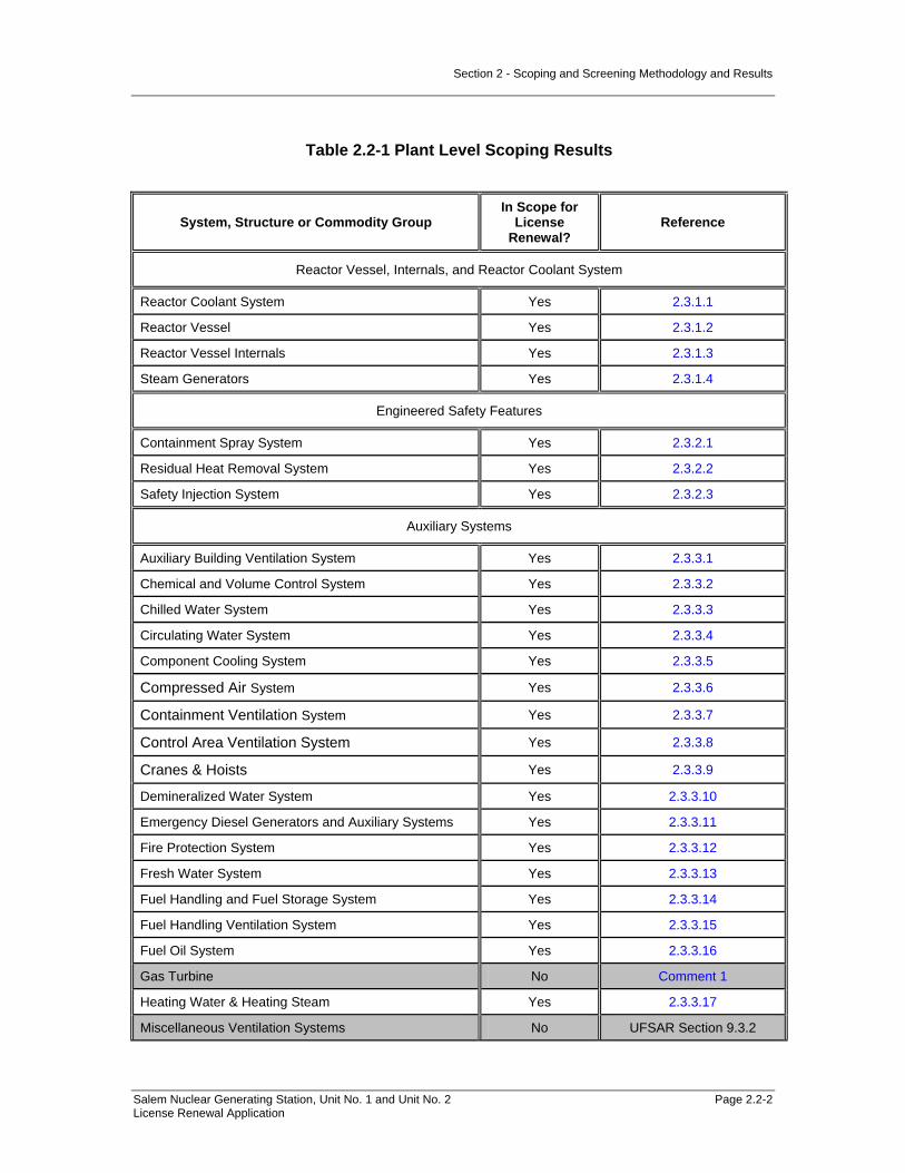
Section 2 - Scoping and Screening Methodology and Results
Salem Nuclear Generating Station, Unit No. 1 and Unit No. 2 Page 2.2-2 License Renewal Application
Table 2.2-1 Plant Level Scoping Results
System, Structure or Commodity Group In Scope for
License Renewal?
Reference
Reactor Vessel, Internals, and Reactor Coolant System
Reactor Coolant System Yes 2.3.1.1
Reactor Vessel Yes 2.3.1.2
Reactor Vessel Internals Yes 2.3.1.3
Steam Generators Yes 2.3.1.4
Engineered Safety Features
Containment Spray System Yes 2.3.2.1
Residual Heat Removal System Yes 2.3.2.2
Safety Injection System Yes 2.3.2.3
Auxiliary Systems
Auxiliary Building Ventilation System Yes 2.3.3.1
Chemical and Volume Control System Yes 2.3.3.2
Chilled Water System Yes 2.3.3.3
Circulating Water System Yes 2.3.3.4
Component Cooling System Yes 2.3.3.5
Compressed Air System Yes 2.3.3.6
Containment Ventilation System Yes 2.3.3.7
Control Area Ventilation System Yes 2.3.3.8
Cranes & Hoists Yes 2.3.3.9
Demineralized Water System Yes 2.3.3.10
Emergency Diesel Generators and Auxiliary Systems Yes 2.3.3.11
Fire Protection System Yes 2.3.3.12
Fresh Water System Yes 2.3.3.13
Fuel Handling and Fuel Storage System Yes 2.3.3.14
Fuel Handling Ventilation System Yes 2.3.3.15
Fuel Oil System Yes 2.3.3.16
Gas Turbine No Comment 1
Heating Water & Heating Steam Yes 2.3.3.17
Miscellaneous Ventilation Systems No UFSAR Section 9.3.2
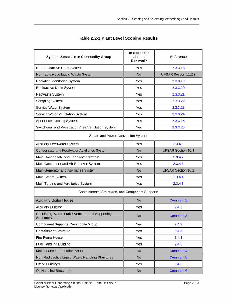
Section 2 - Scoping and Screening Methodology and Results
Salem Nuclear Generating Station, Unit No. 1 and Unit No. 2 Page 2.2-3 License Renewal Application
Table 2.2-1 Plant Level Scoping Results
System, Structure or Commodity Group In Scope for
License Renewal?
Reference
Non-radioactive Drain System Yes 2.3.3.18
Non-radioactive Liquid Waste System No UFSAR Section 11.2.8
Radiation Monitoring System Yes 2.3.3.19
Radioactive Drain System Yes 2.3.3.20
Radwaste System Yes 2.3.3.21
Sampling System Yes 2.3.3.22
Service Water System Yes 2.3.3.23
Service Water Ventilation System Yes 2.3.3.24
Spent Fuel Cooling System Yes 2.3.3.25
Switchgear and Penetration Area Ventilation System Yes 2.3.3.26
Steam and Power Conversion System
Auxiliary Feedwater System Yes 2.3.4.1
Condensate and Feedwater Auxiliaries System No UFSAR Section 10.4
Main Condensate and Feedwater System Yes 2.3.4.2
Main Condenser and Air Removal System Yes 2.3.4.3
Main Generator and Auxiliaries System No UFSAR Section 10.2
Main Steam System Yes 2.3.4.4
Main Turbine and Auxiliaries System Yes 2.3.4.5
Containments, Structures, and Component Supports
Auxiliary Boiler House No Comment 2
Auxiliary Building Yes 2.4.1
Circulating Water Intake Structure and Supporting Structures No Comment 3
Component Supports Commodity Group Yes 2.4.2
Containment Structure Yes 2.4.3
Fire Pump House Yes 2.4.4
Fuel Handling Building Yes 2.4.5
Maintenance Fabrication Shop No Comment 4
Non-Radioactive Liquid Waste Handling Structures No Comment 5
Office Buildings Yes 2.4.6
Oil Handling Structures No Comment 6

Section 2 - Scoping and Screening Methodology and Results
Salem Nuclear Generating Station, Unit No. 1 and Unit No. 2 Page 2.2-4 License Renewal Application
Table 2.2-1 Plant Level Scoping Results
System, Structure or Commodity Group In Scope for
License Renewal?
Reference
Penetration Areas Yes 2.4.7
Pipe Tunnel Yes 2.4.8
Piping and Component Insulation Commodity Group Yes 2.4.9
Salem Warehouse No. 2 No Comment 7
SBO Compressor Building Yes 2.4.10
Security Structures No Comment 8
Service Building Yes 2.4.11
Service Water Accumulator Enclosures Yes 2.4.12
Service Water Intake Yes 2.4.13
Sewage Lift Station Electrical Shed No Comment 9
Shoreline Protection and Dike Yes 2.4.14
Switchyard Yes 2.4.15
Tritium Reclamation Plant No Comment 10
Technical Support Center (TSC) Diesel House No Comment 11
Turbine Building Yes 2.4.16
Unit 3 Gas Turbine Facility No Comment 12
Water Treatment Buildings No Comment 13
Well Pump Houses No Comment 14
Yard Structures Yes 2.4.17
Electrical and Instrumentation and Control (I&C) Systems
115-volt System Yes UFSAR Section 8.3.1.4
13KV System Yes UFSAR Section 8.3.1.1
230-volt System Yes UFSAR Section 8.3.1.3
4160-volt System Yes UFSAR Section 8.3.1.2
460-volt System Yes UFSAR Section 8.3.1.3
Cathodic Protection System No UFSAR Section 10.4.1
Communication System Yes UFSAR Section 9.5.2
DC Power System Yes UFSAR Section 8.3.2
Electrical Commodities Yes 2.5.2.5
Heat Trace System Yes UFSAR Section 9.3.4

Section 2 - Scoping and Screening Methodology and Results
Salem Nuclear Generating Station, Unit No. 1 and Unit No. 2 Page 2.2-5 License Renewal Application
Table 2.2-1 Plant Level Scoping Results
System, Structure or Commodity Group In Scope for
License Renewal?
Reference
Lighting System Yes UFSAR Section 9.5.3
Meteorological Tower No UFSAR Section 2.3.3
Miscellaneous Instrumentation Systems No UFSAR Section 7.7.2
Offsite-500KV System Yes UFSAR Section 8.2
Plant Alarm and Annunciator System Yes UFSAR Section 7.10
Reactor Control System Yes UFSAR Section 7.7
Reactor Protection System Yes UFSAR Section 7.2.2
Security System No UFSAR Section 13.7
Comments:
1. The Gas Turbine is a nonsafety-related system that provides power to the grid during periods of peak demand. The Gas Turbine is not relied upon in the safety analysis or plant evaluations to perform a function that demonstrates compliance with the Commission's regulations for Station Blackout (10 CFR 50.63).
2. The Auxiliary Boiler House is a nonsafety-related structure, designed to commercial grade standards. The structure is separated from safety-related systems, structures, and components (SSCs) such that its failure would not impact a safety-related function. The purpose of the Auxiliary Boiler House is to provide physical support, shelter, and protection for the nonsafety-related Heating Water & Heating Steam System components and its supporting systems. The Auxiliary Boiler House does not perform an intended function for license renewal and is not in the scope of license renewal.
3. The Circulating Water Structure and Supporting Structures are nonsafety-related and separated from safety-related systems, structures, and components such that their failure would not impact a safety-related function. The purpose of the Circulating Water Structures is to provide physical support, shelter, and protection for the Circulating Water System components that provide cooling water to the main condenser. The Circulating Water Structures do not perform an intended function for license renewal and are not in the scope of license renewal. The outer reinforced concrete walls of the Circulating Water Intake Structure are credited to limit wave run-up and are separately evaluated with the Shoreline Protection and Dike.

Section 2 - Scoping and Screening Methodology and Results
Salem Nuclear Generating Station, Unit No. 1 and Unit No. 2 Page 2.2-6 License Renewal Application
4. The purpose of the Maintenance Fabrication Shop is to house equipment, tools, and materials used by maintenance personnel for onsite fabrication of items required for plant maintenance and modifications. Evaluation of systems and components inside the fabrication shop determined that they do not perform an intended function for license renewal and are not in the scope of license renewal.
5. The Non-Radioactive Liquid Waste Handling Structures are classified nonsafety-related and separated from safety-related systems, structures, and components such that their failure would not impact a safety-related function. The purpose of the Non-radioactive Liquid Waste Handling Structures is to provide physical support, shelter and protection for the nonsafety-related Non-radioactive Liquid Waste System and supporting systems. The system is designed to treat industrial wastewater from the plant and groundwater from the tritium remediation wells to allow their discharge in compliance with the NJPDES permit. The Non-radioactive Liquid Waste System is not in the scope of license renewal. Evaluation of the Non-radioactive Liquid Waste Handling Structures determined that they do not perform an intended function delineated in 10 CFR 54.4 (a) and are not in scope for license renewal.
6. The purpose of the Oil Handling Structures is to provide structural support, shelter, and protection for the housed components associated with fuel oil including commercial foam fire suppression for the fuel oil tank storage area and to contain water and waste oil and sludge associated with the separation of waste oil from waste water. The Oil Handling Structures do not perform an intended function and are not in scope for license renewal.
7. Salem Warehouse No. 2 is classified nonsafety-related and separated from safety-related systems, structures, and components such that its failure would not impact a safety-related function. The purpose of Salem Warehouse No. 2 is to house equipment, tools, and materials used for maintenance of plant facilities. Evaluation of the Salem Warehouse No. 2 determined that it does not perform an intended function and are not in scope for license renewal.
8. The purpose of the Security Structures is to provide support, shelter, and protection for the plant security force and equipment required to control access into the protected area, surrounded by a perimeter fence, as required by 10 CFR 73. The Security Center also provides access and a security control point to the protected area. The Security Structures do not perform an intended function and are not in scope for license renewal.
9. The purpose of the Sewage Lift Station Electrical Shed is to provide structural support, shelter, and protection for the housed components associated with pumping and control of sewage. Components housed in the Sewage Lift Station Electrical Shed include the associated pumping and piping components, panels and enclosures, and electrical commodities. The Sewage Lift Station Electrical Shed does not perform an intended function and is not in scope for license renewal.
10. The purpose of the Tritium Reclamation Plant enclosure is to provide structural support, shelter and protection for the nonsafety-related components associated with sampling, dilution and disposal of groundwater samples.
Section 2 - Scoping and Screening Methodology and Results
Salem Nuclear Generating Station, Unit No. 1 and Unit No. 2 Page 2.2-7 License Renewal Application
Evaluation of the Tritium Reclamation Plant enclosure determined that it does not perform an intended function and it is not in scope for license renewal.
11. The Technical Support Center (TSC) Diesel House provides structural support, shelter, and protection for the TSC diesel generator and its auxiliary systems and components. The generator provides emergency power to the TSC lighting and ventilation in the event of a loss of the normal power source. The TSC Diesel House is nonsafety-related and separated from safety-related systems, structures, and components such that its failure would not impact a safety-related function. The TSC Diesel House does not perform an intended function and is not in scope for license renewal.
12. The purpose of the Unit 3 Gas Turbine Facility is to provide structural support, shelter, and protection for the gas turbines and generator, supporting systems, and components. The gas turbine is not credited for station blackout. The generator unit is rated at approximately 40 MW and is normally used for peaking purposes. The gas turbines and generator do not perform a license renewal intended function and are not in scope for license renewal.
13. The Water Treatment Buildings are classified nonsafety-related and separated from safety-related systems, structures, and components such that their failure would not impact a safety-related function. The purpose of the Water Treatment Buildings is to provide structural support, shelter and protection for the nonsafety-related Demineralized Water System components and its supporting systems. Evaluation of the Water Treatment Buildings determined that they do not perform an intended function and are not in scope for license renewal.
14. The purpose of the Well Pump Houses is to provide structural support, shelter and protection for the nonsafety-related Fresh Water System components and its supporting systems. Components housed in the pump houses include the deep well water pumps, associated piping and piping components, panels and enclosures, and electrical commodities. Scoping of systems inside the Well Pump Houses determined that they do not perform an intended function and are not in scope for license renewal.

Section 2 – Scoping and Screening Methodology Results
Salem Nuclear Generating Station, Unit No. 1 and Unit No. 2 Page 2.3-1 License Renewal Application
2.3 SCOPING AND SCREENING RESULTS: MECHANICAL
2.3.1 REACTOR VESSEL, INTERNALS, AND REACTOR COOLANT SYSTEM
The following systems are addressed in this section:
• Reactor Coolant System (2.3.1.1)
• Reactor Vessel (2.3.1.2)
• Reactor Vessel Internals (2.3.1.3)
• Steam Generators (2.3.1.4)
Section 2 – Scoping and Screening Methodology Results
Salem Nuclear Generating Station, Unit No. 1 and Unit No. 2 Page 2.3-2 License Renewal Application
2.3.1.1 Reactor Coolant System
System Purpose The Reactor Coolant System is a normally operating system designed to circulate sub-cooled reactor coolant to transfer heat from the reactor core to the secondary fluid in four (4) steam generators during normal operation, or anticipated operational occurrences. The system is capable of transferring this heat using forced circulation with the reactor coolant pumps during normal operation, or using natural circulation when necessary during emergency operations. The Reactor Coolant System consists of the following plant systems: reactor coolant system and reactor vessel level instrumentation. The Reactor Coolant System consists of the following major components: pressurizer, reactor coolant pressure boundary components (hot leg piping and cold leg piping), reactor coolant pumps and their oil lift system, pressurizer relief tank, pressurizer heaters, pressurizer surge line, pressurizer spray line, and the reactor head vent piping. Reactor vessel level instrumentation consists of two redundant trains of hydraulic components and instrumentation. The Reactor Coolant System is in scope for license renewal. The Reactor Coolant System has interfaces with several other systems and components that are not within the license renewal boundary of the Reactor Coolant System, and are evaluated separately. These systems include the Chemical and Volume Control, Compressed Air, Component Cooling, Radwaste, Reactor Vessel, Residual Heat Removal, Safety Injection, Sampling, and Steam Generators. The purpose of the Reactor Coolant System is to circulate reactor coolant either by forced circulation with the reactor coolant pumps, including the flywheels, to provide motive force if the reactor coolant pump motors stop, or by natural circulation to transfer sufficient heat from the reactor core to the secondary fluid in the Steam Generators during normal operation and anticipated operational occurrences so that reactor core thermal limits are not exceeded. The Reactor Coolant System provides a pressure boundary to separate fission products from the environment. The Reactor Coolant System provides a flow path for emergency core cooling from the Safety Injection and Residual Heat Removal Systems. The Reactor Coolant System provides a core cooling flow path for decay heat removal during cold shutdown and refueling conditions. The purpose of the pressurizer is to establish and maintain the Reactor Coolant System pressure within prescribed limits through use of the pressurizer heaters and the pressurizer spray line. The pressurizer heaters are comprised of seventy-eight individual electric immersion heaters that penetrate the lower portion of the pressurizer. A spray nozzle installed on the upper head of the pressurizer is connected to the spray line and provides relatively cool cold leg water to the pressurizer. Over-pressure protection is provided by power-operated relief valves and code safety valves that discharge into the pressurizer relief tank to ensure that the code safety limits are not exceeded. The pressurizer also provides a steam surge chamber and a water reserve to accommodate reactor coolant density changes during operation via the pressurizer surge line. The purpose of the four (4) controlled-leakage reactor coolant pumps is to provide heat-up during plant start-up and for reactor coolant circulation during normal operations. The reactor coolant pumps are each equipped with a flywheel to extend coast down in the event of a pump trip. The austenitic stainless steel hot leg piping connects the Reactor Vessel outlet nozzles to the inlet of the Steam Generators. The austenitic stainless steel cold leg piping connects the outlet of the Steam Generators with the suction of the reactor coolant pumps, and extends from the discharge of the reactor coolant pump to the inlet nozzles of the Reactor Vessel.

Section 2 – Scoping and Screening Methodology Results
Salem Nuclear Generating Station, Unit No. 1 and Unit No. 2 Page 2.3-3 License Renewal Application
The pressurizer relief tank is a steel tank internally lined with a protective coating and equipped with an inlet sparger, vents, and drains. Its purpose is to accept fluid from the pressurizer, relief valves, valve stem leak-offs, and the reactor vessel head vent, and then discharge the accumulated fluid to the Radwaste System. The purpose of the reactor vessel level instrumentation portion of the Reactor Coolant System is to monitor the water level in the Reactor Vessel when the reactor coolant pumps are not running, and determine the relative void content in the Reactor Coolant System when one or more reactor coolant pumps are operating. The Reactor Coolant System is required for all plant conditions when fuel is in the Reactor Vessel. The Reactor Coolant System accomplishes its purposes by circulating reactor coolant through the reactor core to transfer sufficient heat from the reactor core to the steam generators during normal operations and anticipated operational occurrences by means of the reactor coolant pumps and flywheels, piping, pressurizer and related components, and the reactor head vent. The Reactor Coolant System also accomplishes its purpose by monitoring the liquid level in the reactor vessel using the reactor vessel level instrumentation. System Operation The Reactor Coolant System is comprised of the pressurizer, reactor coolant pressure boundary components (hot leg piping and cold leg piping), reactor coolant pumps and their oil lift system, pressurizer relief tank, pressurizer heaters, pressurizer surge line, pressurizer spray line, the reactor head vent, and the reactor vessel level instrumentation. The Reactor Coolant System consists of four (4) primary loops each containing hot leg piping, a Steam Generator, cold leg piping, and a reactor coolant pump. The Reactor Coolant System flowpath begins at the Reactor Vessel where heated coolant exits the Reactor Vessel out of the outlet nozzles and continues through the hot leg piping up to the primary channel head of the Steam Generators. Coolant flow continues through the Steam Generator u-tubes, transferring heat to the steam and water on the shell side. Coolant flow exits the Steam Generator primary channel head and continues through the cold leg piping to the suction of the reactor coolant pumps. Flow is discharged from the reactor coolant pumps through the cold leg piping to the inlet nozzles of the Reactor Vessel. The pressurizer is connected to the hot leg piping via the pressurizer surge line. The pressurizer surge line permits unrestricted flow between the Reactor Coolant System and the pressurizer to maintain the Reactor Coolant System pressure and accommodate system volume changes. The pressurizer has two (2) power-operated relief valves and three (3) code safety valves for over-pressure protection. The pressurizer controls the Reactor Coolant System pressure by means of the pressurizer heaters and the spray line. The pressurizer heaters are designed to replace heat lost during normal operation to raise the saturation temperature, which raises the pressure. The pressurizer spray line provides a path for relatively cool cold leg reactor coolant to spray into the steam space at the top of the pressurizer to condense steam to reduce the system pressure. An auxiliary spray line supplies the pressurizer with borated water from the Chemical and Volume Control System during emergency conditions. Sampling lines off of the pressurizer steam and liquid spaces forwards samples to the Sampling System.

Section 2 – Scoping and Screening Methodology Results
Salem Nuclear Generating Station, Unit No. 1 and Unit No. 2 Page 2.3-4 License Renewal Application
During normal operation, controlled leakoff from the reactor coolant pumps' number 1 seal flows to the Chemical and Volume Control System, and controlled leakoff from the numbers 2 and 3 seals drain directly to the reactor coolant drain tank, which is part of the Radwaste System. Cooling water from the Component Cooling System flows into the reactor coolant pump motor upper and lower bearings, and the thermal barrier heat exchanger, and returns back into the Component Cooling System. The oil lift system is actuated before starting the reactor coolant pumps to pump oil from the upper and lower oil reservoirs to the reactor coolant pump upper bearing assembly. The pressurizer relief tank receives vented reactor coolant from the pressurizer, the reactor vessel head vent, relief valves, and valve stem leak-offs, and discharges accumulated fluid to the Radwaste System. Nitrogen from the Radwaste System is added to the pressurizer relief tank to maintain low concentrations of hydrogen and oxygen. The atmosphere of the pressurizer relief tank is vented to the Radwaste System header, and includes a separate branch for gas sampling. During normal operation, coolant flow exits the Reactor Coolant System at the letdown lines connected to the cold leg piping, and also from the excess letdown line connected to the cold leg piping, and enters into the Chemical and Volume Control System. Make-up water from the Chemical and Volume Control System (charging) enters the Reactor Coolant System at the cold leg piping, and also through the pressurizer auxiliary spray piping. During normal shutdown operations, coolant flow is transferred from the hot leg piping to the suction of the residual heat removal pumps, discharged through the residual heat removal heat exchangers, and re-enters the Reactor Coolant System. During accident conditions, high head injection flow begins at the Chemical and Volume Control System centrifugal charging pumps, continues through the boron injection tank, and enters the cold leg piping of the Reactor Coolant System. Intermediate head injection flow begins at the safety injection pumps and enters the cold leg piping of the Reactor Coolant System. Low head injection flow starts at the refueling water storage tank that provides a source of water to the suction of the residual heat removal pumps, whose discharge continues through the residual heat removal heat exchangers, and enters the Reactor Coolant System. The safety injection accumulators also discharge into the cold leg piping of the Reactor Coolant System. Reactor vessel level instrumentation has tubing connections to the Reactor Vessel and monitors the water level in the Reactor Vessel by means of differential pressure transmitters and sensors. It provides display in the control room, and does not provide any automatic actuation signals for equipment. For more information, refer to UFSAR sections 4.1, 5.1 through 5.6, and 7.3.1. System Boundary The Reactor Coolant System boundary includes the pressurizer, reactor coolant pressure boundary components (hot leg piping and cold leg piping), reactor coolant pumps and their oil lift system, pressurizer relief tank, pressurizer heaters, pressurizer surge line, and pressurizer spray line, including the auxiliary spray piping back to its first isolation valve.

Section 2 – Scoping and Screening Methodology Results
Salem Nuclear Generating Station, Unit No. 1 and Unit No. 2 Page 2.3-5 License Renewal Application
The Reactor Coolant System scoping boundary begins at the Reactor Vessel outlet nozzle safe end to pipe welds, continues through the hot leg piping to the Steam Generator inlet nozzle safe end to pipe welds. The Steam Generators are evaluated as a separate license renewal system. The Reactor Coolant System boundary continues from the Steam Generator outlet safe ends to pipe welds through the cold leg piping to the suction of the reactor coolant pump. The Reactor Coolant System boundary continues from the reactor coolant pump discharge through the cold leg piping to the Reactor Vessel inlet nozzle pipe to safe end welds. The Reactor Vessel is evaluated as a separate license renewal system. The pressurizer surge line that is connected from the hot leg to the pressurizer lower head is included in the Reactor Coolant System boundary, as well as the pressurizer spray line that is connected from the cold leg piping to the spray nozzle internal to the pressurizer. The Reactor Coolant System scoping boundary includes the pressurizer attached piping, and code safety valves and power-operated relief valves. The Compressed Air System accumulators, tubing from the accumulators to the air actuator of the power-operated relief valves, and solenoid valves are evaluated with the Compressed Air System. The Reactor Coolant System scoping boundary includes the Reactor Vessel head vent piping downstream of the control room operated vent valves and their downstream common isolation valve. The scoping boundary also includes the reactor vessel level instrumentation tubing downstream of the seal table isolation valve. The reactor coolant sample line just downstream of the first isolation valve, and the pressurizer steam and liquid space sample lines to the first isolation valve are included in the scope of the Reactor Coolant System. The pressurizer relief tank internal spray, drain, nitrogen, vent header, and gas sampling piping up to, and including an isolation valve as designated on the license renewal boundary drawings are included in the scope of the Reactor Coolant System. The selected isolation valve at the boundary between the Reactor Coolant System and another license renewal system is where the piping classification changes from the Reactor Coolant System specification to another system's specification. The Reactor Coolant System boundary includes piping up to the first isolation valve for the charging interfaces of the Chemical and Volume Control System. The Reactor Coolant System boundary includes piping up to the second isolation valve for the letdown interfaces of the Chemical and Volume Control System. The boundary also includes piping downstream of the reactor coolant pump seal water return header relief valve. The Reactor Coolant System has an interface with the Residual Heat Removal System at a hot leg. The boundary extends from this interconnection and terminates at the first Residual Heat Removal System isolation valve. The Reactor Coolant System has several interfaces with the Safety Injection System. The Reactor Coolant System scoping boundary extends from each of the hot leg and cold leg interconnections and terminates at the respective Safety Injection System check valve. The Reactor Coolant System boundary extends from the drain lines interconnections and terminates at the second normally closed valve.

Section 2 – Scoping and Screening Methodology Results
Salem Nuclear Generating Station, Unit No. 1 and Unit No. 2 Page 2.3-6 License Renewal Application
The Reactor Coolant System scoping boundary for seal water leak-off is at each of the reactor coolant pump's weld neck flange. Not included in the Reactor Coolant System boundary are the reactor coolant pump upper and lower bearing heat exchangers, and the thermal barrier heat exchanger which are evaluated with the Component Cooling System for license renewal scoping. The Reactor Coolant System scoping boundary also includes the pressure retaining portions of Reactor Coolant System instrumentation and its associated piping, tubing, and instrumentation root valves. Also included in the license renewal scoping boundary of the Reactor Coolant System are those portions of nonsafety-related piping and equipment that extend beyond the safety-related/nonsafety-related interface up to the location of the first seismic anchor, or to a point no longer in proximity to equipment performing a safety-related function, whichever extends furthest. This includes the nonsafety-related portions of the systems located within the Containment Structure, shown in red. Included in this boundary are pressure retaining components relied upon to preserve the leakage boundary intended function of this portion of the system. This includes the reactor coolant pump oil lift system piping and components. For more information, refer to the license renewal boundary drawing for identification of this boundary, shown in red. Not included in the Reactor Coolant System license renewal scoping boundary are the following interfacing systems, which are separately evaluated as license renewal systems: Chemical and Volume Control Component Cooling Compressed Air Radwaste Reactor Vessel Residual Heat Removal Safety Injection Sampling Steam Generators Reason for Scope Determination The Reactor Coolant System meets 10 CFR 54.4(a)(1) because it is a safety-related system that is relied upon to remain functional during and following design basis events. It meets 10 CFR 54.4 (a)(2) because failure of non safety-related portions of the system could prevent satisfactory accomplishment of function(s) identified for 10 CFR 54.4 (a)(1). It also meets 10 CFR 54.4(a)(3) because it is relied upon in safety analyses or plant evaluations to perform a function that demonstrates compliance with the Commission's regulations for Fire Protection (10 CFR 50.48), Environmental Qualification (10 CFR 50.49), and for Station Blackout (10 CFR 50.63). The Reactor Coolant System is not relied upon in safety analyses or plant evaluations to perform a function that demonstrates compliance with the Commission's regulations for Pressurized Thermal Shock (10 CFR 50.61) and Anticipated Transient Without Scram (10 CFR 50.62). System Intended Functions 1. Provide and maintain sufficient reactor coolant inventory for core cooling. The Reactor Coolant System transfers the heat generated in the core to the Steam Generators. Coolant is

Section 2 – Scoping and Screening Methodology Results
Salem Nuclear Generating Station, Unit No. 1 and Unit No. 2 Page 2.3-7 License Renewal Application
circulated at the flow and temperature required for achieving the reactor core thermal-hydraulic performance. The Reactor Coolant System circulates reactor coolant either by forced circulation with the reactor coolant pumps, including the flywheels when the pumps are stopped, or by natural circulation to transfer sufficient heat from the reactor core to the steam generator secondary fluid during normal operation and anticipated operational occurrences so that reactor core thermal limits are not exceeded. The Reactor Coolant System has high point vents that are used to aid in natural recirculation. 10 CFR 54.4(a)(1) 2. Provide reactor coolant pressure boundary. The Reactor Coolant System provides a boundary for containing the coolant under normal operating temperature and pressure conditions. 10 CFR 54.4(a)(1) 3. Sense process conditions and generate signals for reactor trip or engineered safety features actuation. The reactor vessel level instrumentation system monitors the level of water in the Reactor Vessel and provides display to the control room for operator manual action. 10 CFR 54.4(a)(1) 4. Resist nonsafety-related SSC failure that could prevent satisfactory accomplishment of a safety-related function. The reactor coolant system contains nonsafety-related components that have the potential for spatial interaction with safety-related components. There is nonsafety-related instrumentation attached to safety-related tubing. 10 CFR 54.4(a)(2) 5. Relied upon in safety analyses or plant evaluations to perform a function that demonstrates compliance with the Commission's regulations for Fire Protection (10 CFR 50.48). The Reactor Coolant System contains components that are credited in the Post Fire Safe Shutdown Analyses. 10 CFR 54.4(a)(3) 6. Relied upon in safety analyses or plant evaluations to perform a function that demonstrates compliance with the Commission's regulations for Environmental Qualification (10 CFR 50.49). The Reactor Coolant System contains environmental qualification components that are safety-related and in a harsh environment. 10 CFR 54.4(a)(3) 7. Relied upon in safety analyses or plant evaluations to perform a function that demonstrates compliance with the Commission's regulations for Station Blackout (10 CFR 50.63). The Reactor Coolant System is used during shutdown and coping during a SBO event. 10 CFR 54.4(a)(3) UFSAR References 4.1 5.1-5.6 7.3.1 License Renewal Boundary Drawings Unit 1: LR-205201 Sheet 1 LR-205201 Sheet 2 LR-205201 Sheet 3 LR-205227 Sheet 3
Section 2 – Scoping and Screening Methodology Results
Salem Nuclear Generating Station, Unit No. 1 and Unit No. 2 Page 2.3-8 License Renewal Application
LR-205228 Sheet 2 LR-205228 Sheet 3 LR-205232 Sheet 2 LR-205234 Sheet 1 LR-205234 Sheet 3 LR-205234 Sheet 4 Unit 2: LR-205301 Sheet 1 LR-205301 Sheet 2 LR-205301 Sheet 3 LR-205328 Sheet 2 LR-205328 Sheet 3 LR-205332 Sheet 2 LR-205334 Sheet 1 LR-205334 Sheet 3 LR-205334 Sheet 4 Unit Common: None

Section 2 – Scoping and Screening Methodology Results
Salem Nuclear Generating Station, Unit No. 1 and Unit No. 2 Page 2.3-9 License Renewal Application
Table 2.3.1-1 Reactor Coolant System Components Subject to Aging Management Review
Component Type Intended Function
Bolting Mechanical Closure
Bolting (Class 1) Mechanical Closure
Class 1 Piping, Fittings and Branch Connections < NPS 4" Direct Flow (thermal sleeve)
Class 1 Piping, Fittings and Branch Connections < NPS 4" Pressure Boundary
Heat exchanger components (Reactor Coolant Pump Bearing Oil and Thermal Barrier)
Evaluated with the Component Cooling System
Hoses (Reactor Coolant Pump Oil Lift component) Leakage Boundary
Piping and Fittings Leakage Boundary
Piping and Fittings Pressure Boundary
Piping and Fittings (Class 1) Pressure Boundary
Pressurizer Pressure Boundary
Pressurizer (integral support - skirt) Structural Support
Pressurizer (manway, insert, diaphragm) Pressure Boundary
Pressurizer (thermal sleeves) Direct Flow
Pressurizer instrumentation penetrations, heater sheaths and sleeves, heater support plates
Pressure Boundary
Pressurizer surge and steam space nozzles, safe ends, and welds Pressure Boundary
Pump Casing (Reactor Coolant Pump Oil Lift Pump) Leakage Boundary
Pump Casing (Reactor Coolant Pump) Pressure Boundary
Reactor Coolant Pressure Boundary Components (hot leg and cold leg piping) Pressure Boundary
Restricting Orifices Leakage Boundary
Rupture disks Pressure Boundary

Section 2 – Scoping and Screening Methodology Results
Salem Nuclear Generating Station, Unit No. 1 and Unit No. 2 Page 2.3-10 License Renewal Application
Component Type Intended Function
Sight Glasses (Reactor Coolant Pump Oil Lift component) Leakage Boundary
Sparger Spray
Spray Nozzles (Pressurizer and Pressurizer Relief Tank)) Spray
Strainer Body (Reactor Coolant Pump Oil Lift component) Leakage Boundary
Tanks (Pressurizer Relief Tank) Pressure Boundary
Tanks (Reactor Coolant Pump Upper and Lower Oil Reservoirs) Leakage Boundary
Thermowell Pressure Boundary
Valve Body Leakage Boundary
Valve Body Pressure Boundary
Valve Body (Class 1) Pressure Boundary The aging management review results for these components are provided in: Table 3.1.2-1 Reactor Coolant System Summary of Aging Management Evaluation

Section 2 – Scoping and Screening Methodology Results
Salem Nuclear Generating Station, Unit No. 1 and Unit No. 2 Page 2.3-11 License Renewal Application
2.3.1.2 Reactor Vessel
System Purpose The Reactor Vessel is a normally operating system designed to contain pressure and heat in the core, and transfer this heat to the Reactor Coolant System. The Reactor Vessel also includes the control rod drive mechanisms that provide the ability to control reactivity in the core. The control rod drive mechanism fans, motors, and plenum are evaluated as part of the Containment Ventilation System. The Reactor Vessel consists of the following major components: reactor vessel, the integrated head assembly, control rod drive mechanisms, the attached vent, flange leak-off, drain, and level instrumentation piping and components, the vessel shells, upper shell flange, nozzle shell course, nozzles, safe ends, closure studs, the lower head, the core support lug, and the primary nozzle supports. The Reactor Vessel is in scope for license renewal. The Reactor Vessel has interfaces with other systems that are not in the license renewal boundary of the Reactor Vessel, however are evaluated separately. These systems are Containment Ventilation, Radwaste, Reactor Coolant, and the Reactor Vessel Internals. The purpose of the Reactor Vessel is to maintain the reactor vessel pressure boundary and provide structural support for the reactor vessel internals, core, and control rod drive mechanisms. There are four (4) primary inlet flow nozzles, and four (4) primary outlet nozzles provided for cold leg flow and hot leg flow, respectively. The Reactor Vessel provides a boundary to prevent fission product release to the environment. Each of the control rod drive mechanisms consists of a drive rod assembly, latch assembly, pressure housing, and operating coil stacks. The control rod drive mechanisms provide a means of reactivity control in the reactor by monitoring and controlling the motion and position of the control rod cluster assemblies. The Reactor Vessel is required for plant start-up, normal plant operations, and normal shutdown. The Reactor Vessel accomplishes its purpose by providing structural support for the reactor vessel internals and by providing a pressure boundary for the circulation of fluid from the Reactor Coolant System during normal operations and anticipated operational occurrences. System Operation The Reactor Vessel is comprised of the Reactor Vessel, the integrated head assembly, control rod drive mechanisms, the attached vent, flange leak-off, drain, and level instrumentation piping and components, the vessel shells, upper shell flange, nozzle shell course, nozzles, safe ends, closure studs, the lower head, and the primary nozzle supports. Reactor coolant enters the Reactor Vessel through four (4) primary inlet nozzles, flows downward through the annuli between the core barrel and thermal shield, and between the thermal shield and the vessel wall. The reactor coolant flow then travels upward through the diffuser plate, up through the nuclear core, absorbing heat from the fuel bundles, and exits the Reactor Vessel through the four (4) exit nozzles where it continues through the hot leg piping to the respective Steam Generator. The vessel shell material is protected against fast neutron flux by the thermal shield. Approximately 6 percent of the flow bypasses the core and is unavailable for heat removal from the core. This small amount of bypass is comprised of
Section 2 – Scoping and Screening Methodology Results
Salem Nuclear Generating Station, Unit No. 1 and Unit No. 2 Page 2.3-12 License Renewal Application
bypass flow around the primary inlet nozzles, guide tube assemblies, instrument thimble, baffle wall, and around the bottom of the reactor vessel head for cooling. Control rod position is manually controlled during start-up. The control rods are manually withdrawn as required to bring the reactor critical and raise thermal power. Automatic control is provided after achieving 15% of full rated thermal power on the turbine. The control rod drive mechanisms provide a rapid insertion of negative reactivity into the core by removing power to all control rod drive mechanisms. Power is removed from the control rod drive mechanisms when directed by the Reactor Protection System, or when the reactor trip breakers open. The Reactor Vessel is filled following refueling by drawing vacuum through the Reactor Coolant System pressurizer vent valve. The Reactor Vessel is then allowed to refill from the refueling water storage tank via the Residual Heat Removal System. Leak-off from the o-ring regions between the Reactor Vessel shell flange and integrated head assembly flows to the reactor coolant drain tank. For more information, refer to UFSAR Sections 5.4, 5.5, and 5.6.5. System Boundary The Reactor Vessel boundary begins at the reactor vessel inlet nozzle safe ends and terminates at the outlet nozzle safe ends. There are a series of plates and baffles assisting in flow distribution through the core. These plates and baffles are separately evaluated with the Reactor Vessel Internals. The license renewal scoping boundary of the Reactor Vessel encompasses the reactor vessel, the integrated head assembly, control rod drive mechanisms, the vessel shells, upper shell flange, nozzle shell course, nozzles, safe ends, closure studs, the lower head, and the primary nozzle supports. Also included are the flange leak-off connections and attached leak-off piping from the reactor vessel head flange to the air-operated isolation valve and the integrated head assembly vent piping up to, and including the first manual isolation valve that is downstream of the remote-operated solenoid valves. Additionally, the boundary includes the level instrumentation piping from the integrated head assembly to the second isolation valve that is part of the reactor vessel level instrumentation system. The remaining portion of the reactor vessel level instrumentation system is evaluated separately with the Reactor Coolant System. The Reactor Vessel nozzles include the four (4) inlet nozzles, four (4) outlet nozzles, and control rod drive mechanism nozzles. The boundary includes the fifty-three (53) control rod drive mechanism housing nozzles for Unit 1 and fifty-seven (57) control rod drive mechanism housing nozzles for Unit 2, as well as, the fifty-eight (58) lower head penetration tubes for incore flux thimbles and instrumentation. All associated piping and components contained within the flow path described above are included in the Reactor Vessel evaluation boundary. Not included in the boundary are the following plant systems that interface with the Reactor Vessel, but are evaluated as part of the Containment Ventilation System: (1) rod drive ventilation, (2) reactor nozzle support ventilation, and (3) reactor shield ventilation. The three (3) rod drive cooling fans located on top of the integrated head assembly, including the motors

Section 2 – Scoping and Screening Methodology Results
Salem Nuclear Generating Station, Unit No. 1 and Unit No. 2 Page 2.3-13 License Renewal Application
and plenum, are evaluated with the Containment Ventilation System. Not included in the Reactor Vessel license renewal scoping boundary are the following interfacing systems that are evaluated separately: Containment Ventilation System Radwaste System Reactor Coolant Reactor Vessel Internals Reason for Scope Determination The Reactor Vessel meets 10 CFR 54.4(a)(1) because it is a safety-related system that is relied upon to remain functional during and following design basis events. It meets 10 CFR 54.4 (a)(2) because failure of non safety-related portions of the system could prevent satisfactory accomplishment of function(s) identified for 10 CFR 54.4 (a)(1). It also meets 10 CFR 54.4(a)(3) because it is relied upon in safety analyses or plant evaluations to perform a function that demonstrates compliance with the Commission's regulations for Fire Protection (10 CFR 50.48), Environmental Qualification (10 CFR 50.49), Pressurized Thermal Shock (10 CFR 50.61), Anticipated Transient Without Scram (10 CFR 50.62), and for Station Blackout (10 CFR 50.63). System Intended Functions 1. Provide reactor coolant pressure boundary. The Reactor Vessel provides a barrier against the release of reactor coolant and radioactive material to the Containment Structure. 10 CFR 54.4(a)(1) 2. Maintain reactor core assembly geometry. The Reactor Vessel houses the core and reactor internals. 10 CFR 54.4(a)(1) 3. Achieve and maintain the reactor core subcritical for any mode of normal operation or event. The control rod drive mechanisms portion of the Reactor Vessel provides automatic and manual means of positioning rod control cluster assemblies in the core. The integrated head assembly supports the deadweight of the control rod drive mechanisms while the seismic platform provides lateral support at the top of each control rod drive mechanism. The control rod drive mechanisms missile shield, which is permanently attached to the structure, provides missile protection for containment if a control rod drive mechanism ejected. 10 CFR 54.4(a)(1) 4. Introduce emergency negative reactivity to make the reactor subcritical. The control rod drive mechanisms permit rapid insertion of the control rods following a reactor trip. 10 CFR 54.4(a)(1) 5. Resist nonsafety-related SCC failure that could prevent satisfactory accomplishment of a safety-related function. The integrated head assembly contains nonsafety-related components that have the potential for spatial interactions with safety-related SCCs. 10 CFR 54.4 (a)(2) 6. Relied upon in safety analyses or plant evaluations to perform a function that demonstrates compliance with the Commission's regulations for Fire Protection (10 CFR 50.48). The control rod drive mechanisms are used to control movement of the control rods to achieve and maintain the reactor core sub-critical following a reactor trip. Additionally, the air operated

Section 2 – Scoping and Screening Methodology Results
Salem Nuclear Generating Station, Unit No. 1 and Unit No. 2 Page 2.3-14 License Renewal Application
head vent valves are credited in the Post Fire Safe Shutdown Analyses. 10 CFR 54.4(a)(3) 7. Relied upon in safety analyses or plant evaluations to perform a function that demonstrates compliance with the Commission's regulations for Environmental Qualification (10 CFR 50.49). The Reactor Vessel consists of components that are in the Environmental Qualification program. 10 CFR 54.4(a)(3) 8. Relied upon in safety analyses or plant evaluations to perform a function that demonstrates compliance with the Commission's regulations for Pressurized Thermal Shock (10 CFR 50.61). The reactor vessel beltline shell, including plates, forgings, and welds are subject to Pressurized Thermal Shock (PTS) analyses. 10 CFR 54.4(a)(3) 9. Relied upon in safety analyses or plant evaluations to perform a function that demonstrates compliance with the Commission's regulations for Anticipated Transients Without Scram (10 CFR 50.62). The control rod drive mechanisms are used to control movement of the control rods to achieve and maintain the reactor core sub-critical following a reactor trip or demand for a reactor trip. 10 CFR 54.4(a)(3) 10. Relied upon in safety analyses or plant evaluations to perform a function that demonstrates compliance with the Commission's regulations for Station Blackout (10 CFR 50.63). Rod control is a function credited for Station Blackout analysis. 10 CFR 54.4(a)(3) UFSAR References 5.4 5.5 5.6.5 License Renewal Boundary Drawings Unit 1: LR-205201 Sheet 2 Unit 2: LR-205301 Sheet 1 Unit Common: None

Section 2 – Scoping and Screening Methodology Results
Salem Nuclear Generating Station, Unit No. 1 and Unit No. 2 Page 2.3-15 License Renewal Application
Table 2.3.1-2 Reactor Vessel Components Subject to Aging Management Review
Component Type Intended Function
Bolting Mechanical Closure
Bolting Structural Support
Class 1 Piping, Fittings and Branch Connections < NPS 4" (Head Vent Piping)
Pressure Boundary
Class 1 Piping, Fittings and Branch Connections < NPS 4" (Leak-Off Piping) Pressure Boundary
Control Rod Assembly Pressure Boundary
Nozzle (BMI) Pressure Boundary
Nozzle (CRDM) Pressure Boundary
Nozzle (Integrated Head Assembly Vent) Pressure Boundary
Nozzle (Primary) Pressure Boundary
Nozzle (RVLIS) Pressure Boundary
Nozzle Safe Ends and Welds Pressure Boundary
Reactor Vessel (Closure Head) Pressure Boundary
Reactor Vessel (Lower Head, Upper Shell Flange, Nozzle Shell Course) Pressure Boundary
Reactor Vessel (Nozzle Supports) Structural Support
Reactor Vessel (Upper Shell, Intermediate Shell, Lower Shell, and Welds)
Pressure Boundary
Restricting Orifices Pressure Boundary
Restricting Orifices Throttle
Steel components: All structural steel Structural Support
Valve Body Pressure Boundary

Section 2 – Scoping and Screening Methodology Results
Salem Nuclear Generating Station, Unit No. 1 and Unit No. 2 Page 2.3-16 License Renewal Application
The aging management review results for these components are provided in: Table 3.1.2-2 Reactor Vessel Summary of Aging Management Evaluation

Section 2 – Scoping and Screening Methodology Results
Salem Nuclear Generating Station, Unit No. 1 and Unit No. 2 Page 2.3-17 License Renewal Application
2.3.1.3 Reactor Vessel Internals
System Purpose The Reactor Vessel Internals is a normally operating system designed to maintain reactor core assembly geometry, to achieve and maintain the reactor core subcritical for any mode of operation or design basis event, and to introduce negative reactivity to make the reactor subcritical. The Reactor Vessel Internals consist of the upper core support structure, the lower core support structure, and the incore instrumentation support structure, where each of these major components has distinct purposes. Also included are the flux thimble tubes that extend from the penetrations on the Reactor Vessel lower head up to the seal table. The Reactor Vessel Internals also include the fuel assemblies and the rod cluster control assemblies that are supported by all three structures. In addition, the major structural welds that form or join the major structures, the minor structural welds joining parts such as lifting lugs, supports, and tubes to the major structures, and the fasteners and alignment pins that guide, align, and fasten the major structures are within the scope of the Reactor Vessel Internals. The Reactor Vessel Internals is in scope for license renewal. The Reactor Vessel Internals has interfaces with other systems and components that are not within the license renewal boundary of the Reactor Vessel Internals, and are evaluated separately. This includes the Reactor Vessel. The overall purpose of the Reactor Vessel Internals is to direct reactor coolant through the core to achieve acceptable flow distribution and to restrict bypass flow, so that heat transfer performance requirements are met for all modes of operation. The purpose of the upper core support structure is to contain the guide tube assemblies that shield and guide the control rod drive shafts and control rods. This structure engages the top of the fuel assemblies and provides structural support experienced by transverse loadings from coolant cross flow and other design conditions. The upper core support structure also provides structural support for vertical loads from the fuel, hydraulic forces, control rod dynamics, and other design loadings. The purpose of the lower core support structure is to form a periphery enclosure of the core including core baffles and a bottom flow distribution plate for efficient flow distribution, provide neutron shielding by means of the thermal shield, and to provide structural support experienced by transverse loadings from coolant cross flow and other design conditions. The lower core support structure also provides structural support for vertical loads from the fuel, hydraulic forces, control rod dynamics, and other design loadings. The purpose of the incore instrumentation support structure is to provide structural support for the bottom-mounted incore instrumentation (flux thimbles and thermocouples) and to maintain a pressure boundary between the reactor coolant and containment atmosphere. The purpose of the fuel assemblies is to generate heat from the fuel rods, maintain a coolable fuel rod geometry, and promote efficient heat transfer from the nuclear fuel to the reactor coolant by means of directing flow upwards from the bottom nozzle through the assembly and
Section 2 – Scoping and Screening Methodology Results
Salem Nuclear Generating Station, Unit No. 1 and Unit No. 2 Page 2.3-18 License Renewal Application
out the top nozzle. The top and bottom nozzles with the guide rods provide dimensional stability of the fuel rods, permit insertion of control rods for control of reactivity, and permit insertion of incore instrumentation. The purpose of the rod cluster control assemblies is to provide reactivity control for shutdown, reactivity changes due to reactor coolant temperature changes within the power range, the power coefficient of reactivity, and also void formation. The Reactor Vessel Internals is required for all modes of operation, unless the reactor vessel is completely defueled. The Reactor Vessel Internals accomplishes its purposes by providing the necessary support structures for the circulation of reactor coolant through the reactor core to remove heat from the reactor core. System Operation The Reactor Vessel Internals is comprised of the upper core support structure, lower core support structure, incore instrumentation support structure, fuel assemblies, and the rod cluster control assemblies. The upper core support structure consists of the upper support assembly, the upper core plate, support columns, and the control rod guide assemblies. The support columns establish the spacing between the upper support assembly and the upper core plate. The upper core plate consists of openings for the control rod guide tubes, and for the distribution of reactor coolant flow via orifice plates, integral flow mixers, and open holes. The control rod guide tube assemblies shield and guide the control rod drive shafts and control rods. They are fastened to the upper core plate and are guided by pins into the upper core plate for proper orientation and support. A large circumferential hold down spring restrains axial movements. The entire upper core support structure is removed as a unit during refueling operations to permit access to the fuel assemblies. The lower core support structure remains in place in the reactor vessel during most refueling operations and is only removed to perform scheduled inspections. The lower core support structure is supported at its upper flange from a ledge in the reactor vessel and its lower end is restrained from transverse motion by a radial support system attached to the reactor vessel wall. The lower core support structure consists of the core barrel, the core baffles, the flow distribution (diffuser) plate, the lower core plate and support columns, the thermal shield, and the core support forging, which is welded to the core barrel. The core barrel supports and contains the fuel assemblies. The core barrel directs coolant flow upwards through the reactor vessel by means of the bottom-mounted flow distribution plate and the core baffles. The lower core support plate provides support for the support columns, reactor coolant flow distribution, and support and orientation of the fuel assemblies. The one-piece thermal shield provides neutron shielding when fuel is present in the core, and is fixed to the core barrel at the top with rigid bolted connections. The bottom of the thermal shield is connected to the core barrel by means of axial flexures. This bottom support allows for differential axial growth of the shield/core barrel but restricts radial or horizontal movement of the bottom of the thermal shield. Specimen guides are welded to the thermal shield and allow for irradiation of test samples during operations. The core support is contoured to the bottom of the reactor vessel and receives the weight, hydraulic, and control rod dynamic loadings.

Section 2 – Scoping and Screening Methodology Results
Salem Nuclear Generating Station, Unit No. 1 and Unit No. 2 Page 2.3-19 License Renewal Application
The incore instrumentation support structure is a series of instrumentation guide columns (cruciforms) and tubing assemblies that support the bottom-mounted incore instrumentation. The incore instrumentation, including flux thimbles and thermocouples, penetrate through the reactor vessel lower head via penetration nozzles. High pressure tubing runs extend from the bottom of the reactor vessel lower head to the seal table located in the seal table room. The reactor coolant flowpath begins at the reactor vessel inlet nozzles where reactor coolant flow enters the reactor vessel and impinges against the upper core barrel. Flow continues down the annulus between the thermal shield and the reactor vessel wall, with some flow going between the thermal shield and the core barrel. Flow continues between the core barrel radial support members to the lower head plenum. The coolant flow is redirected upwards by means of the annular orientation of the Reactor Vessel Internals from the lower head plenum through flow diffuser plate, lower core plate, and through the fuel assemblies where it absorbs heat from the fuel rods. The core baffles contain the coolant flow at the core periphery as it travels upwards through the fuel assemblies. Flow exits the reactor core and continues into the upper vessel internals through the upper core plate, passing through and across the support columns and guide tube assemblies, exiting through the upper core barrel, and it exits the reactor vessel through the outlet nozzles. The reactor core has one hundred and ninety-three (193) fuel assemblies arranged in a square lattice that approximates the shape of a cylinder. The reactivity of the core is controlled by fifty-three (53) rod cluster control assemblies. For more information, refer to UFSAR Sections 4.1, and 4.2.2. System Boundary The license renewal scoping boundary of the Reactor Vessel Internals is comprised of the upper core support structure, lower core support structure, and incore instrumentation support structure. The upper core support structure consists of the guide tube assemblies, the upper core plate, upper support assembly, fuel assembly guide pins, a large circumferential spring, and support columns. The lower core support structure consists of the core barrel, the core baffles, a flow distribution (diffuser) plate, the lower core plate and support columns, the thermal shield, and the core support forging. The incore instrumentation support structure consists of the instrumentation guide columns and instrumentation tube assemblies. The Reactor Vessel Internals scoping boundary includes the incore monitoring tubing assemblies, the flux thimbles, from inside of the vessel through the seal table up to, and including the seal table downstream isolation valve. Also included in the Reactor Vessel Internals are the fuel assemblies and the rod cluster control assemblies. Also included in the Reactor Vessel Internals are the rod cluster control assemblies’ spider assemblies including the control rodlets. The spider assembly is the boundary with the control rod drive mechanisms which are evaluated with the Reactor Vessel. Not included in the Reactor Vessel Internals license renewal scoping boundary is the Reactor Vessel, which is separately evaluated as a license renewal system. Reason for Scope Determination The Reactor Vessel Internals meets 10 CFR 54.4(a)(1) because it is a safety-related system that is relied upon to remain functional during and following design basis events. It meets 10
Section 2 – Scoping and Screening Methodology Results
Salem Nuclear Generating Station, Unit No. 1 and Unit No. 2 Page 2.3-20 License Renewal Application
CFR 54.4(a)(2) because failure of non safety-related portions of the system could prevent satisfactory accomplishment of function(s) identified for 10 CFR 54.4(a)(1). The Reactor Vessel Internals is not relied upon in safety analyses or plant evaluations to perform a function that demonstrates compliance with the Commission's regulations for Fire Protection (10 CFR 50.48), Environmental Qualification (10 CFR 50.49), Pressurized Thermal Shock (10 CFR 50.61), Anticipated Transient Without Scram (10 CFR 50.62), or Station Blackout (10 CFR 50.63). System Intended Functions 1. Maintain reactor core assembly geometry. The Reactor Vessel Internals maintains core assembly geometry within the reactor to ensure core cooling, core reactivity control, and the integrity of the fuel cladding as a radioactive material barrier. 10 CFR 54.4(a)(1) 2. Achieve and maintain the reactor core subcritical for any mode of normal operation or event. The rod cluster control assemblies adjust the concentration of the neutron absorber in the core. 10 CFR 54.4(a)(1) 3. Introduce emergency negative reactivity to make the reactor subcritical. Following a reactor trip signal, all rod cluster control assemblies are released into the core to initiate a complete reactor trip. 10 CFR 54.4(a)(1) 4. Resist nonsafety-related SCC failure that could prevent satisfactory accomplishment of a safety-related function. The control rods are nonsafety-related components that have the potential for spatial interactions with safety-related SCCs. 10 CFR 54.4(a)(2) UFSAR References 4.1 4.2.2 License Renewal Boundary Drawings Unit 1: LR-205201 Sheet 1 Unit 2: LR-205301 Sheet 1 Unit Common: None

Section 2 – Scoping and Screening Methodology Results
Salem Nuclear Generating Station, Unit No. 1 and Unit No. 2 Page 2.3-21 License Renewal Application
Table 2.3.1-3 Reactor Vessel Internals Components Subject to Aging Management Review
Component Type Intended Function
Control Rod Assembly None - Short Lived
Core Barrel (lower) Structural Support to maintain core configuration and flow distribution
Core Barrel (upper) Structural Support to maintain core configuration and flow distribution
Core Barrel Assembly (alignment pins) Structural Support to maintain core configuration and flow distribution
Core Barrel Assembly (baffle bolt lock bars)
Structural Support to maintain core configuration and flow distribution
Core Barrel Assembly (baffle former assembly - plates)
Structural Support to maintain core configuration and flow distribution
Core Barrel Assembly (core barrel to thermal shield bolts and dowels)
Structural Support to maintain core configuration and flow distribution
Core Barrel Assembly (flange) Structural Support to maintain core configuration and flow distribution
Core Barrel Assembly (lock bar, baffle-former, barrel-former, and baffle-edge bolting)
Structural Support to maintain core configuration and flow distribution
Core Barrel Assembly (outlet nozzle) Structural Support to maintain core configuration and flow distribution
Core Barrel Assembly (spray nozzles) Structural Support to maintain core configuration and flow distribution
Fuel Assembly (Short-lived) None - Short Lived
Lower Internal Assembly (axial flexures: thermal shield to core barrel)
Structural Support to maintain core configuration and flow distribution
Lower Internal Assembly (clevis block bolts)
Structural Support to maintain core configuration and flow distribution
Lower Internal Assembly (clevis block lock keys)
Structural Support to maintain core configuration and flow distribution
Lower Internal Assembly (clevis blocks and inserts)
Structural Support to maintain core configuration and flow distribution
Lower Internal Assembly (core support dome)
Structural Support to maintain core configuration and flow distribution

Section 2 – Scoping and Screening Methodology Results
Salem Nuclear Generating Station, Unit No. 1 and Unit No. 2 Page 2.3-22 License Renewal Application
Component Type Intended Function
Lower Internal Assembly (core support, including core support lugs, columns and sleeves)
Structural Support to maintain core configuration and flow distribution
Lower Internal Assembly (flow distributor (diffuser) plate)
Structural Support to maintain core configuration and flow distribution
Lower Internal Assembly (fuel assembly locating pin bolts)
Structural Support to maintain core configuration and flow distribution
Lower Internal Assembly (fuel assembly locating pins and lockcaps)
Structural Support to maintain core configuration and flow distribution
Lower Internal Assembly (inserts for clevis blocks, including lock bars and dowels)
Structural Support to maintain core configuration and flow distribution
Lower Internal Assembly (irradiation sample access plugs)
Structural Support to maintain core configuration and flow distribution
Lower Internal Assembly (irradiation sample guide bolts)
Structural Support to maintain core configuration and flow distribution
Lower Internal Assembly (irradiation sample guide lock caps)
Structural Support to maintain core configuration and flow distribution
Lower Internal Assembly (irradiation sample guide)
None - Short Lived
Lower Internal Assembly (lower core plate)
Structural Support to maintain core configuration and flow distribution
Lower Internal Assembly (lower core support energy absorbers)
Structural Support to maintain core configuration and flow distribution
Lower Internal Assembly (lower core support guide post and housing)
Structural Support to maintain core configuration and flow distribution
Lower Internal Assembly (lower core support ring)
Structural Support to maintain core configuration and flow distribution
Lower Internal Assembly (lower radial support keys)
Structural Support to maintain core configuration and flow distribution
Lower Internal Assembly (lower support base bolt lock keys)
Structural Support to maintain core configuration and flow distribution
Lower Internal Assembly (lower support base bolts)
Structural Support to maintain core configuration and flow distribution
Lower Internal Assembly (lower support column bolts)
Structural Support to maintain core configuration and flow distribution

Section 2 – Scoping and Screening Methodology Results
Salem Nuclear Generating Station, Unit No. 1 and Unit No. 2 Page 2.3-23 License Renewal Application
Component Type Intended Function
Lower Internal Assembly (lower support column nuts)
Structural Support to maintain core configuration and flow distribution
Lower Internal Assembly (lower support lock keys)
Structural Support to maintain core configuration and flow distribution
RCCA Guide Tube Assemblies (bolts) Structural Support to maintain core configuration and flow distribution
RCCA Guide Tube Assemblies (enclosures)
Structural Support to maintain core configuration and flow distribution
RCCA guide tube assemblies (flexures; inserts)
Structural Support to maintain core configuration and flow distribution
RCCA guide tube assemblies (guide pins in tubes)
Structural Support to maintain core configuration and flow distribution
RCCA guide tube assemblies (lock bars) Structural Support to maintain core configuration and flow distribution
RCCA guide tube assemblies (lower flanges)
Structural Support to maintain core configuration and flow distribution
RCCA guide tube assemblies (pins, anti-rotation studs, and nuts)
Structural Support to maintain core configuration and flow distribution
RCCA guide tube assemblies (sheaths) Structural Support to maintain core configuration and flow distribution
RCCA guide tube assemblies (support pin cover plate)
Structural Support to maintain core configuration and flow distribution
RCCA guide tube assemblies (support pin fasteners and nuts)
Structural Support to maintain core configuration and flow distribution
RCCA guide tube assemblies (tubes, housing plates, and guide plates)
Structural Support to maintain core configuration and flow distribution
RCCA guide tube assemblies (upper guide tube)
Structural Support to maintain core configuration and flow distribution
Reactor Vessel Internals (core support locking nut)
Structural Support to maintain core configuration and flow distribution
Reactor Vessel Internals (flux thimbles - tubes)
Pressure Boundary
Reactor Vessel Internals (incore guide cruciforms)
Structural Support to maintain core configuration and flow distribution

Section 2 – Scoping and Screening Methodology Results
Salem Nuclear Generating Station, Unit No. 1 and Unit No. 2 Page 2.3-24 License Renewal Application
Component Type Intended Function
Reactor Vessel Internals (incore guide tube column bodies)
Structural Support to maintain core configuration and flow distribution
Reactor Vessel Internals (incore guide tube extensions)
Structural Support to maintain core configuration and flow distribution
Reactor Vessel Internals (incore instrument guide extension bolt lock caps)
Structural Support to maintain core configuration and flow distribution
Reactor Vessel Internals (incore instrument guide extension bolts)
Structural Support to maintain core configuration and flow distribution
Reactor Vessel Internals (incore instrument guide extension collars)
Structural Support to maintain core configuration and flow distribution
Reactor Vessel Internals (incore instrument guide extension nuts)
Structural Support to maintain core configuration and flow distribution
Reactor Vessel Internals (incore instrument guide tube extension bars)
Structural Support to maintain core configuration and flow distribution
Reactor Vessel Internals (manway cover assembly)
Pressure Boundary
Reactor Vessel Internals (secondary core support)
Structural Support to maintain core configuration and flow distribution
Thermal Shield Shielding
Thermal Shield (adjustment plugs) Structural Support to maintain core configuration and flow distribution
Thermal Shield (bolts and dowels) Structural Support to maintain core configuration and flow distribution
Upper Internals Assembly (beam and ribs bolts)
Structural Support to maintain core configuration and flow distribution
Upper Internals Assembly (beam and ribs lock keys)
Structural Support to maintain core configuration and flow distribution
Upper Internals Assembly (capped top thermocouple columns)
Pressure Boundary
Upper Internals Assembly (deep beam rib and stiffener, and ribs)
Structural Support to maintain core configuration and flow distribution
Upper Internals Assembly (fuel assembly locating pins)
Structural Support to maintain core configuration and flow distribution
Upper Internals Assembly (head to vessel alignment pin bolt locking caps)
Structural Support to maintain core configuration and flow distribution
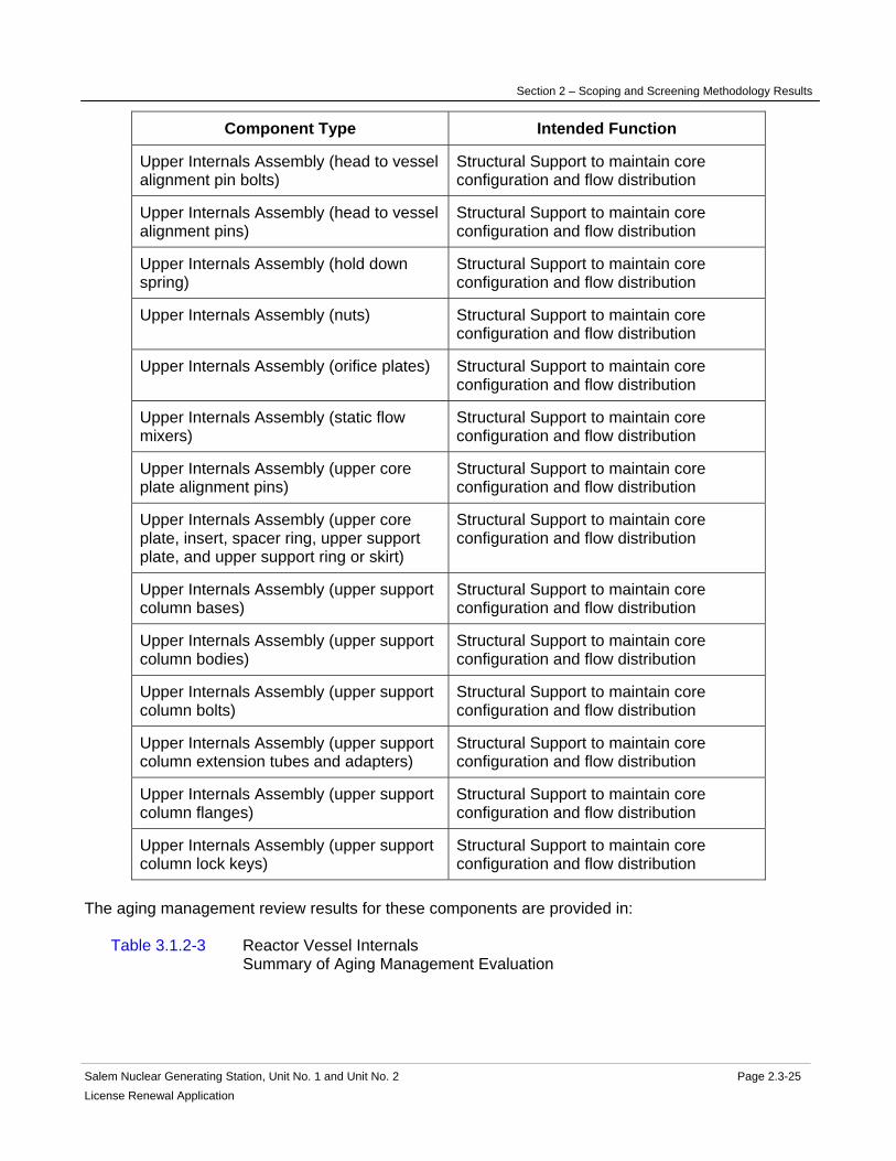
Section 2 – Scoping and Screening Methodology Results
Salem Nuclear Generating Station, Unit No. 1 and Unit No. 2 Page 2.3-25 License Renewal Application
Component Type Intended Function
Upper Internals Assembly (head to vessel alignment pin bolts)
Structural Support to maintain core configuration and flow distribution
Upper Internals Assembly (head to vessel alignment pins)
Structural Support to maintain core configuration and flow distribution
Upper Internals Assembly (hold down spring)
Structural Support to maintain core configuration and flow distribution
Upper Internals Assembly (nuts) Structural Support to maintain core configuration and flow distribution
Upper Internals Assembly (orifice plates) Structural Support to maintain core configuration and flow distribution
Upper Internals Assembly (static flow mixers)
Structural Support to maintain core configuration and flow distribution
Upper Internals Assembly (upper core plate alignment pins)
Structural Support to maintain core configuration and flow distribution
Upper Internals Assembly (upper core plate, insert, spacer ring, upper support plate, and upper support ring or skirt)
Structural Support to maintain core configuration and flow distribution
Upper Internals Assembly (upper support column bases)
Structural Support to maintain core configuration and flow distribution
Upper Internals Assembly (upper support column bodies)
Structural Support to maintain core configuration and flow distribution
Upper Internals Assembly (upper support column bolts)
Structural Support to maintain core configuration and flow distribution
Upper Internals Assembly (upper support column extension tubes and adapters)
Structural Support to maintain core configuration and flow distribution
Upper Internals Assembly (upper support column flanges)
Structural Support to maintain core configuration and flow distribution
Upper Internals Assembly (upper support column lock keys)
Structural Support to maintain core configuration and flow distribution
The aging management review results for these components are provided in: Table 3.1.2-3 Reactor Vessel Internals Summary of Aging Management Evaluation

Section 2 – Scoping and Screening Methodology Results
Salem Nuclear Generating Station, Unit No. 1 and Unit No. 2 Page 2.3-26 License Renewal Application
2.3.1.4 Steam Generators
System Purpose The Steam Generators are a normally operating system designed to serve as a heat sink for the reactor coolant, to supply dry saturated steam to the turbine/generator, and to provide a barrier to prevent fission products and activated corrosion products in the reactor coolant from entering the steam system. The Steam Generators consists of the following plant systems: steam generators and steam generator drains and blowdown. The major components of the Steam Generators are the four (4) steam generators per Unit. Unit 1 has Westinghouse Model F recirculating steam generators. Unit 2 has AREVA 61/19T recirculating steam generators. The steam generator drains and blowdown consists of the steam generator blowdown tank, the blowdown analyzer drains receiver tank, blowdown analyzer drains pumps, piping, and valves. The Steam Generators are in scope for license renewal. However, portions of the Steam Generators are not required to perform an intended function and are not in scope. The Steam Generators have interfaces with several other systems and components that are not within the license renewal boundary of the Steam Generators, and are evaluated separately. These include the Main Condensate and Feedwater, Main Steam, Radioactive Drain, Reactor Coolant, and Sampling systems. The Steam Generators have several purposes. The steam generators transfer heat from the reactor coolant to the main feedwater via the four recirculating steam generators during normal operation and anticipated operational occurrences so that reactor core thermal limits are not exceeded. The steam generators provide a pressure boundary to separate fission products from the environment. The high-pressure (reactor coolant pressure) parts of the steam generators consist of the primary channel head, manways, primary nozzles, the tubesheet, tubes, and tube plugs. The steam generators provide indication of steam generator skin temperature, water level, and pressure via instrumentation and controls. The level instrumentation actuates a reactor trip signal upon a low-low steam generator water level. They also provide input into the ATWS Mitigation System Actuation Circuitry (AMSAC). The steam generators provide containment isolation. Outboard containment isolation valves of the steam generator drains and blowdown automatically close upon either a high radiation signal or initiation of auxiliary feedwater. The steam generators provide high-quality steam. Main feedwater enters the steam generator at the inlet nozzle, through the feedwater ring, and flows over the tube bundle where it absorbs heat from the primary coolant and forms steam. The steam passes through two stages of moisture separation before exiting the steam generators at the outlet main steam nozzle.

Section 2 – Scoping and Screening Methodology Results
Salem Nuclear Generating Station, Unit No. 1 and Unit No. 2 Page 2.3-27 License Renewal Application
The steam generator drains and blowdown system provides a means of draining the steam generators, and to provide a means of removing impurities from the steam generators to maintain secondary feedwater chemistry within prescribed limits. The steam generator drains and blowdown has the capability of draining and processing the steam generator secondary inventory and permitting blowdown from the steam generators via tanks, piping, and valves. The steam generators are located at a higher elevation than the reactor core, thus natural circulation is assured for removal of decay heat if forced primary flow is lost. The steam generators accomplish these purposes by providing the heat transfer from the Reactor Coolant System during normal operations and anticipated operational occurrences via the four recirculating Steam Generators, piping, and valves. The Steam Generators are required for all plant conditions when fuel is in the reactor vessel. System Operation The Steam Generators are comprised of the steam generators, steam generator blowdown tank, steam generator blowdown analyzer drains receiver tank, steam generator blowdown analyzer drains pumps, piping, and valves. The Steam Generators consist of four (4) steam generators per Unit that are large shell and tube heat exchangers. Unit 1 has Westinghouse Model F recirculating steam generators. Unit 2 has AREVA 61/19T recirculating steam generators. Reactor coolant flows through the u-shaped tubes on the primary side, and main feedwater flows through the shell on the secondary side. On the primary side, reactor coolant from the Reactor Coolant System enters the primary channel head at the inlet primary nozzle, passes through the tubesheet and continues through the vertical U-tubes, transferring heat to the secondary fluid, flows back into the primary channel head, and through the outlet primary coolant nozzle. The primary channel head includes a divider plate to separate inlet and outlet primary flow. On the secondary side, main feedwater from the Main Condensate and Feedwater System enters the steam generator through the main feedwater nozzle into the feedwater ring. Inverted J-tubes fitted onto the feedwater ring direct the main feedwater flow into the region above the shell and tube bundle annulus section, and downwards through the annulus downcomer, where it turns upward to flow over the tubes. Low-quality steam is generated as the water flows upward in the tube bundle. The steam passes through two stages of moisture separation equipment consisting of vanes and orifices, and exits the steam generator out of the top outlet steam nozzle to the Main Steam System. A programmed water level is maintained in the region above the tube bundle by matching feedwater and steam flow. Both narrow and wide range level indication is provided in the control room. During normal operations, sampling lines off of the steam generators deliver liquid samples to the Sampling System for analyses of secondary water chemistry. The steam generator drain and blowdown normal blowdown flowpath begins at the steam generator shell blowdown nozzle and terminates at the flow control valves. The steam generator drains portion of the drains and blowdown normal blowdown flowpath flows to the steam generator blowdown tank.

Section 2 – Scoping and Screening Methodology Results
Salem Nuclear Generating Station, Unit No. 1 and Unit No. 2 Page 2.3-28 License Renewal Application
During outages when the steam generators are drained, the blowdown flow is directed to the steam generator blowdown tank located in the Auxiliary Building. The blowdown analyzer drains receiver tank and pumps were provided to receive samples from the steam generator analyzers, however they are no longer in service due to relocation of the sampling system lines. For more information, refer to UFSAR Sections 5.5.2 and 10.4.8. System Boundary The Steam Generators scoping boundary includes those portions of the four (4) steam generators associated with maintaining the reactor coolant pressure boundary, and the secondary side pressure boundary. The primary side boundary begins at the inlet primary nozzle safe end-to-pipe weld, one for each steam generator, where reactor coolant enters the inlet primary nozzle, continues into the primary channel head, through the tubes, into the primary channel head, through the outlet primary nozzle, and ends at the outlet primary nozzle safe end-to-pipe weld. The secondary side boundary begins at the main feedwater nozzle safe end-to-pipe weld for each steam generator where feedwater flows enters at the main feedwater nozzle, continues through the feedwater ring and J-tubes, and downwards through the annulus downcomers. The boundary continues upwards across the tubes, through the vessel shell and upper head, through the main steam nozzle, and ends at the main steam nozzle safe end-to-pipe weld. The steam generator sampling line out to the first isolation valve is included in the Steam Generators boundary. The steam generator drain and blowdown boundary begins at the steam generator shell blowdown nozzle, continues through the Containment Structure, and terminates at the flow control valves located in the Turbine Building. All associated piping, components, and instrumentation contained within the flowpaths described above are included in the system evaluation boundary. The Steam Generators scoping boundary also includes the pressure retaining portions of Steam Generators instrumentation and their associated piping, tubing, and instrumentation root valves. Also included in the license renewal scoping boundary of the Steam Generators are those portions of nonsafety-related piping and equipment that extend beyond the safety-related/nonsafety-related interface up to the location of the first seismic anchor, or to a point no longer in proximity to equipment performing a safety-related function, whichever extends furthest. This includes the nonsafety-related portions of the systems located within the Auxiliary Building, shown in red. Included in this boundary are pressure retaining components relied upon to preserve the leakage boundary intended function of this portion of the system. For more information, refer to the license renewal boundary drawing for identification of this boundary, shown in red. Not included in the scope of license renewal is the portion of the Steam Generators located in the Turbine Building, downstream of the flow control valves as these portions of the system is not located within an area in proximity to components performing a safety-related function. Components that are not required to support the system's leakage boundary intended functions are not included in the scope of license renewal.

Section 2 – Scoping and Screening Methodology Results
Salem Nuclear Generating Station, Unit No. 1 and Unit No. 2 Page 2.3-29 License Renewal Application
Not included in the Steam Generators license renewal scoping boundary are the following interfacing systems, which are separately evaluated as license renewal systems: Main Condensate and Feedwater System Main Steam System Radioactive Drain System Reactor Coolant System Sampling System Reason for Scope Determination The Steam Generators System meets 10 CFR 54.4(a)(1) because it is a safety-related system that is relied upon to remain functional during and following design basis events. It meets 10 CFR 54.4(a)(2) because failure of nonsafety-related portions of the system could prevent satisfactory accomplishment of function(s) identified for 10 CFR 54.4(a)(1). It also meets 10 CFR 54.4(a)(3) because it is relied upon in safety analyses or plant evaluations to perform a function that demonstrates compliance with the Commission's regulations for Fire Protection (10 CFR 50.48), Environmental Qualification (10 CFR 50.49), Anticipated Transients Without Scram (10 CFR 50.62), and for Station Blackout (10 CFR 50.63). The Steam Generators System is not relied upon in safety analyses or plant evaluations to perform a function that demonstrates compliance with the Commission's regulations for Pressurized Thermal Shock (10 CFR 50.61). System Intended Functions 1. Provide reactor coolant pressure boundary. The steam generator primary channel head, manways, nozzles, and tubes form a barrier against the release of reactor coolant and radioactive material to the Containment Structure or the Main Steam System. 10 CFR 54.4(a)(1) 2. Sense process conditions and generate signals for reactor trip or engineered safety features actuation. The Steam Generators monitor the level of water in the Steam Generators and actuates a reactor trip upon a low-low steam generator water level signal. 10 CFR 54.4(a)(1) 3. Provide primary containment boundary. The Steam Generators have outboard containment isolation valves on the steam generator blowdown and drains piping that close upon a high radiation signal stemming from the steam generator blowdown and drains liquid radiation monitors, or from an auxiliary feedwater initiation. 10 CFR 54.4(a)(1) 4. Provide secondary heat sink. The Auxiliary Feedwater System provides an alternate source of feedwater to the steam generators, removing heat (including Reactor Coolant pump energy, decay and sensible heat) from the Reactor Coolant System to allow safe shutdown of the reactor for events where the Main Condensate and Feedwater System is unavailable. 10 CFR 54.4(a)(1) 5. Resist nonsafety-related SSC failure that could prevent satisfactory accomplishment of a safety-related function. The steam generator drains and blowdown piping has the potential for spatial interaction with safety-related components. 10 CFR 54.4(a)(2).
Section 2 – Scoping and Screening Methodology Results
Salem Nuclear Generating Station, Unit No. 1 and Unit No. 2 Page 2.3-30 License Renewal Application
6. Relied upon in safety analyses or plant evaluations to perform a function that demonstrates compliance with the Commission's regulations for Fire Protection (10 CFR 50.48). The steam generators are an integral part of the Reactor Coolant, Main Condensate and Feedwater, and Main Steam systems, which are all credited in the Post Fire Safe Shutdown Analyses. 10 CFR 54.4(a)(3) 7. Relied upon in safety analyses or plant evaluations to perform a function that demonstrates compliance with the Commission's regulations for Environmental Qualification (10 CFR 50.49). The Steam Generators contain Environmental Qualification components that are safety-related, and are in a harsh environment. 10 CFR 54.4(a)(3) 8. Relied upon in safety analyses or plant evaluations to perform a function that demonstrates compliance with the Commission's regulations for ATWS (10 CFR 50.62). The Steam Generators provide containment isolation upon receiving a signal of auxiliary feedwater initiation. Also, the Steam Generators level instrumentation input is provided to AMSAC. 10 CFR 54.4(a)(3) 9. Relied upon in safety analyses or plant evaluations to perform a function that demonstrates compliance with the Commission's regulations for Station Blackout (10 CFR 50.63). The Steam Generators provide containment isolation and supports coping and shutdown. 10 CFR 54.4(a)(3) UFSAR References 5.5.2 10.4.8 License Renewal Boundary Drawings Unit 1: LR-205201 Sheet 2 LR-205202 Sheet 3 LR-205203 Sheet 1 LR-205203 Sheet 2 LR-205225 Sheet 1 LR-205225 Sheet 2 Unit 2: LR-205301 Sheet 2 LR-205301 Sheet 3 LR-205302 Sheet 3 LR-205303 Sheet 1 LR-205303 Sheet 2 LR-205325 Sheet 1 LR-205325 Sheet 2 Unit Common: None

Section 2 – Scoping and Screening Methodology Results
Salem Nuclear Generating Station, Unit No. 1 and Unit No. 2 Page 2.3-31 License Renewal Application
Table 2.3.1-4 Steam Generators Components Subject to Aging Management Review
Component Type Intended Function
Bolting Mechanical Closure
Flow Element Leakage Boundary
Piping and Fittings Leakage Boundary
Piping and Fittings Pressure Boundary
Pump Casing (Steam Generator Blowdown Analyzer Drain Pumps)
Leakage Boundary
Spray Nozzles Direct Flow
Steam Generators (Feedwater Ring and Support)
Direct Flow
Steam Generators (Feedwater Ring and Support)
Structural Support
Steam Generators (Inspection Ports and Diaphragm, Handholes and Covers)
Pressure Boundary
Steam Generators (Level Sensing, Sampling, Wet Lay-Up, and Drain Connections)
Pressure Boundary
Steam Generators (Main Feedwater Nozzle Safe Ends)
Pressure Boundary
Steam Generators (Main Feedwater Nozzles)
Pressure Boundary
Steam Generators (Main Steam Nozzle) Pressure Boundary
Steam Generators (Primary Channel Head Divider Plate)
Direct Flow
Steam Generators (Primary Channel Head Drain, Plug, and Welds - Unit 1 only)
Pressure Boundary
Steam Generators (Primary Channel Head, Nozzles, and Manways)
Pressure Boundary
Steam Generators (Primary Manway Cover Inserts - Unit 1 only)
Pressure Boundary

Section 2 – Scoping and Screening Methodology Results
Salem Nuclear Generating Station, Unit No. 1 and Unit No. 2 Page 2.3-32 License Renewal Application
Component Type Intended Function
Steam Generators (Primary Manway Covers)
Pressure Boundary
Steam Generators (Primary Nozzles Safe Ends)
Pressure Boundary
Steam Generators (Secondary Manways and Covers)
Pressure Boundary
Steam Generators (Tube Bundle Tie Rod Assembly and Anti-Vibration Bars)
Structural Support
Steam Generators (Tube Bundle Wrapper)
Direct Flow
Steam Generators (Tube Plugs) Pressure Boundary
Steam Generators (Tube Support Plates) Structural Support
Steam Generators (Tubes) Heat Transfer
Steam Generators (Tubes) Pressure Boundary
Steam Generators (Tubesheet) Pressure Boundary
Steam Generators (Upper Head, Upper Shell, Conical Shell, Lower Shell)
Pressure Boundary
Tanks (steam generator blowdown and drains receiver tanks)
Leakage Boundary
Valve Body Leakage Boundary
Valve Body Pressure Boundary The aging management review results for these components are provided in: Table 3.1.2-4 Steam Generators Summary of Aging Management Evaluation
Section 2 – Scoping and Screening Methodology Results
Salem Nuclear Generating Station, Unit No. 1 and Unit No. 2 Page 2.3-33 License Renewal Application
2.3.2 Engineered Safety Features The following systems are addressed in this section:
• Containment Spray System (2.3.2.1)
• Residual Heat Removal System (2.3.2.2)
• Safety Injection System (2.3.2.3)

Section 2 – Scoping and Screening Methodology Results
Salem Nuclear Generating Station, Unit No. 1 and Unit No. 2 Page 2.3-34 License Renewal Application
2.3.2.1 Containment Spray System
System Purpose The Containment Spray System is a mechanical, standby system designed to reduce containment pressure to nearly atmospheric pressure, to remove airborne fission products from the containment atmosphere and to minimize corrosion of equipment following a Large Break LOCA (LBLOCA). This system also functions with the containment fan coil units to limit containment pressure following a Main Steam-Line Break (MSLB) inside the Containment Structure. The Containment Spray System is in scope for license renewal. The purpose of the Containment Spray System is to remove energy from the environment by transferring heat from the higher temperature atmosphere to the lower temperature spray droplets discharged from spray nozzles. These spray nozzles are arranged on two concentric spray headers located on the inside dome of the Containment Structure. Heat transfer continues until the spray droplets reach the liquid saturation temperature associated with the pressure in the containment, transferring energy from the containment atmosphere to the fluid in the containment sump. Sodium hydroxide is added to the spray to control the sump pH, which maintains the iodine in solution and minimizes corrosive attack on safety-related components following a LOCA. The Containment Spray System accomplishes this purpose following a design basis event by automatically starting the containment spray pumps and opening several motor-operated valves to align the sodium hydroxide tank to the containment spray loops, and then delivering flow to the spray nozzles. The Containment Spray System is automatically initiated on a high-high containment pressure signal. This system can also be actuated manually from the control room. Two other instrument loops provide input to the wide range containment pressure recorders on the control room console following a design basis event. These signals for actuation and indication are provided from the containment pressure transmitters, which sense the containment pressure through the instrument tubing and bellows assembly. The bellows assemblies are located inside the Containment Structure, while the transmitters are located outside the Containment Structure in the Inner Penetration Area. The spray additive tank has a nitrogen overpressure cover gas to prevent absorption of carbon dioxide from the atmosphere into sodium hydroxide solution. This absorption into the sodium hydroxide could cause the formation of sodium carbonate, which could otherwise precipitate out of solution and clog the spray nozzles. The Containment Spray System is designed with two redundant trains. The two redundant trains are required so that a single active failure during the injection phase in the Containment Spray System will not prevent operation of the system or reduce its capacity below that required to reduce and maintain containment pressure at or near atmospheric pressure following a design basis event. System Operation The Containment Spray System is comprised of two redundant loops. Each loop consists of one containment spray pump, one eductor, two sets of nozzles, and the necessary piping, valves, instrumentation, and controls. Under normal operations, there are no required system functions.
Section 2 – Scoping and Screening Methodology Results
Salem Nuclear Generating Station, Unit No. 1 and Unit No. 2 Page 2.3-35 License Renewal Application
In addition, there is a piping interconnection between the two loops that allows for minimum pump recirculation flow to the suction of each pump. This line contains the eductor that allows sodium hydroxide to be drawn out of the spray additive tank into each loop. There are also manual isolation valves that allow a recirculation path back to the refueling water storage tank for the periodic testing of the pumps. There is one additional piping interconnection in the Containment Structure that allows the full flow testing of the containment spray pumps during refueling outages. When the containment pressure reaches the high-high setpoint following a design basis accident, the Reactor Protection System initiates operation of the Containment Spray System. The containment spray pumps are sequenced onto the diesel generators and the system valves on the containment spray pump discharge and spray additive tank outlet valves are aligned for injection to the spray nozzles. At this point, the two containment spray pumps take suction from the refueling water storage tank (evaluated in the Safety Injection System) through the Containment Spray System into the containment atmosphere. The chemical spray solution is injected into the containment atmosphere through the containment spray nozzle headers. As the water level rises in the containment sump and water is emptied from the refueling water storage tank, the control operator manually realigns one loop of the system at the low refueling water storage tank level to take suction from the containment sump through the residual heat removal pumps to the spray nozzles. After the refueling water storage tank reaches the low-low level, the second containment spray pump is stopped, and spray to the containment atmosphere is provided via the containment sump from the Residual Heat Removal System. The sodium hydroxide is injected into the pump minimum recirculation line of the containment spray pumps through the eductors during the injection phase. For more detailed information, see UFSAR Section 6.2.2. System Boundary The Containment Spray System boundary begins at the attachment point on the outlet of the refueling water storage tank and continues through the containment spray pumps. On the discharge side of the containment spray pumps, the redundant piping trains continue through motor-operated valves and end at the individual spray headers located on the inside dome of the Containment Structure. The system boundary also includes the spray additive tank and piping connecting to the eductors as well as the spray additive tank nitrogen piping up to and including the isolation valve to the tank. The boundary includes the containment spray train cross-connect piping and the containment spray pump test line up to the test line isolation valve. In the inner penetration area, the Containment Spray System boundary includes the piping that ends at the downstream of the motor-operated cross-connect valves with the Residual Heat Removal System. The motor-operated valves have packing leak-off lines that are evaluated with the Radioactive Drain System. The pump casings also have drain connections that end at the first isolation valves or flanges off the pump, which are evaluated with the Radioactive Drain System. The Containment Spray System boundary includes the instrument piping that senses containment pressure. There are six penetrations that exit the Containment Structure and

Section 2 – Scoping and Screening Methodology Results
Salem Nuclear Generating Station, Unit No. 1 and Unit No. 2 Page 2.3-36 License Renewal Application
provide the containment pressure input to four instrument loops for the Reactor Protection System and two instrument loops for wide range containment pressure indication. The Containment Spray System boundary begins at the location of the bellows assembly in the Containment Structure where containment pressure is sensed, and continues through the containment penetration instrument tubing and isolation valves in the instrumentation loops. The boundary ends at the pressure transmitters. The containment spray instrumentation boundary includes all associated piping, isolation valves, and mounted instruments for monitoring the specific parameter. There is one additional piping penetration that is used during refueling outages for calibration of instrumentation, which is in scope. The refueling water storage tank is included in the boundary of the Safety Injection System and the containment sump is included in the boundary of the Containment Structure. Not included in the Containment Spray System scoping boundary are the following systems, which are evaluated separately as license renewal systems: Auxiliary Building Ventilation System Radioactive Drain System Radwaste System Reactor Coolant System Reactor Protection System Residual Heat Removal System Safety Injection System Reason for Scope Determination The Containment Spray System meets 10 CFR 54.4(a)(1) because it is a safety-related system that is relied upon to remain functional during and following design basis events. It does not meet 10 CFR 54.4(a)(2) because failure of non-safety-related portions of the system would not prevent satisfactory accomplishment of function(s) identified for 10 CFR 54.4(a)(1). It also meets 10 CFR 54.4(a)(3) because it is relied upon in the safety analyses or plant evaluations to perform a function that demonstrates compliance with the Commission's regulations for Fire Protection (10 CFR 50.48), and Environmental Qualification (10 CFR 50.49). The Containment Spray System is not relied upon in any safety analyses or plant evaluations to perform a function that demonstrates compliance with the Commission's regulation for Pressurized Thermal Shock (10 CFR 50.61), Anticipated Transient Without Scram (10 CFR 50.62), or Station Blackout (10 CFR 50.63). System Intended Functions 1. Sense process conditions and generate signals for reactor trip or engineered safety features actuation. The Containment Spray System includes pressure-sensing instrumentation that provides input to initiate the containment spray function. 10 CFR 54.4(a)(1) 2. Provide primary containment boundary. The Containment Spray System includes containment isolation valves to assure that radioactive material is not inadvertently transferred out of the Containment Structure. 10 CFR 54.4(a)(1) 3. Provide heat removal from primary containment and provide primary containment pressure control. The Containment Spray System includes nozzles that spray into the Containment

Section 2 – Scoping and Screening Methodology Results
Salem Nuclear Generating Station, Unit No. 1 and Unit No. 2 Page 2.3-37 License Renewal Application
Structure; the spray absorbs the heat energy in the containment and the containment pressure is reduced. 10 CFR 54.4(a)(1) 4. Provide removal of radioactive material from the primary containment atmosphere. Sodium hydroxide sprayed from the containment spray nozzles performs the function of iodine scrubbing from a post-LOCA containment atmosphere. 10 CFR 54.4(a)(1) 5. Relied upon in safety analyses or plant evaluations to perform a function that demonstrates compliance with the Commission's regulations for Fire Protection (10 CFR 50.48). Isolation of containment spray on a spurious actuation precludes loss of reactor coolant makeup water from the refueling water storage tank to the containment floor, therefore conserving refueling water storage tank inventory for safe shutdown. 10 CFR 54.4(a)(3) 6. Relied upon in safety analyses or plant evaluations to perform a function that demonstrates compliance with the Commission's regulations for Environmental Qualification (10 CFR 50.49). The Containment Spray System contains instrumentation that is used for automatic actuation of its protective functions and monitoring of conditions following a design basis accident. 10 CFR 54.4(a)(3) UFSAR References 6.2.2.1 6.2.3 15.4 License Renewal Boundary Drawings Unit 1: LR-205234 Sheet 1 LR-205235 Sheet 1 Unit 2: LR-205334 Sheet 1 LR-205335 Sheet 1 Unit Common: None

Section 2 – Scoping and Screening Methodology Results
Salem Nuclear Generating Station, Unit No. 1 and Unit No. 2 Page 2.3-38 License Renewal Application
Table 2.3.2-1 Containment Spray System Components Subject to Aging Management Review
Component Type Intended Function
Bolting Mechanical Closure
Eductor Pressure Boundary
Flow Device Pressure Boundary
Flow Element Pressure Boundary
Piping and Fittings Pressure Boundary
Pump Casing (Containment Spray Pumps)
Pressure Boundary
Spray Nozzles Pressure Boundary
Spray Nozzles Spray
Strainer Body Pressure Boundary
Tanks (Spray Additive Tank) Pressure Boundary
Valve Body Pressure Boundary The aging management review results for these components are provided in: Table 3.2.2-1 Containment Spray System Summary of Aging Management Evaluation

Section 2 – Scoping and Screening Methodology Results
Salem Nuclear Generating Station, Unit No. 1 and Unit No. 2 Page 2.3-39 License Renewal Application
2.3.2.2 Residual Heat Removal System
System Purpose The Residual Heat Removal System is a standby, mechanical emergency core cooling system (ECCS) designed to provide low pressure injection flow and long-term core cooling following a design basis event. The Residual Heat Removal System has several interfaces with other license renewal systems that are in scope, such as, Reactor Coolant, Chemical & Volume Control, Safety Injection, and Component Cooling Systems, which are evaluated separately. The Residual Heat Removal System is in scope for license renewal. The Residual Heat Removal System is designed to remove decay heat from the core and residual heat from the Reactor Coolant System during the latter stages of plant cooldown when pressure is low. The system also maintains the reactor coolant temperature during refueling, and provides a means for filling and draining the reactor cavity and fuel transfer canal during refueling. In the event of a LOCA, the system injects borated water into the reactor vessel via the Safety Injection System for long-term emergency core cooling, and is used for post-LOCA boron precipitation prevention. The system is designed to maintain core cooling for larger break sizes by providing low-pressure injection independent of and in addition to the high-pressure and intermediate-pressure injection provided by the Chemical & Volume Control System and Safety Injection System, respectively. The Residual Heat Removal System has the following purposes: 1. Inject borated water into the core following a LOCA for long-term emergency core cooling. It accomplishes this purpose by taking suction from the refueling water storage tank and injecting into the reactor vessel via the Safety Injection System when Reactor Coolant System pressure decreases below residual heat removal pump discharge pressure. When the refueling water storage tank inventory is reduced to minimum level, suction is transferred to the containment sump. In the event reactor pressure remains higher than the shutoff head of the residual heat removal pumps when the refueling water storage tank level is below the minimum level, the Residual Heat Removal System can be aligned to transfer water from the containment sump to the suction of the Chemical and Volume Control System (high pressure) and Safety Injection System (intermediate pressure) pumps to support continued borated water injection by those systems. 2. Provide containment isolation and integrity for the Residual Heat Removal System. The suction isolation valves from the Reactor Coolant System are interlocked to remain closed when reactor coolant pressure is greater than 375 psig. These isolation valves maintain the Reactor Coolant System pressure boundary to prevent high pressure to low pressure system breaks. 3. Provide containment cooling following a design basis event by injecting water from the containment sump to the containment spray nozzles after the refueling water storage tank is depleted as the primary cooling water source. 4. Remove decay heat from the core and residual heat from the Reactor Coolant System during normal shutdown. It accomplishes this purpose by drawing water from one reactor coolant hot leg and pumping it through one of the two residual heat removal heat exchanger

Section 2 – Scoping and Screening Methodology Results
Salem Nuclear Generating Station, Unit No. 1 and Unit No. 2 Page 2.3-40 License Renewal Application
loops (evaluated with the Component Cooling System) and back to the reactor vessel via the Safety Injection System. 5. Maintain the reactor coolant temperature at a suitable level for refueling. It accomplishes this purpose by removing heat from the reactor coolant, normally using one of two Residual Heat Removal System pumps and heat exchanger trains to maintain reactor coolant temperature below 140 degrees F. 6. Provide a backup means for filling and draining the reactor cavity and the fuel transfer canal (normally performed by the Spent Fuel Cooling System). The Residual Heat Removal System accomplishes filling of the canal above the level of the reactor vessel flange by aligning suction of one residual heat removal pump to the refueling water storage tank. After refueling, the Residual Heat Removal System accomplishes draining of the fuel transfer canal to the level of the reactor vessel flange by aligning one of the residual heat removal pumps from the reactor coolant hot leg, discharging back to the refueling water storage tank. During this operation, the remaining residual heat removal pump continues in normal cooling flow path for decay heat removal. 7. Provide a means of reactor coolant boration and cleanup in preparation for and during refueling operations. The Residual Heat Removal System can be aligned for chemical addition or cleanup while operating in the "letdown booster" mode. In this mode of operation, the residual heat removal letdown booster pump provides additional flow for chemical addition and cleanup at lower reactor coolant pressures in preparation for refueling operations. During normal plant power operation, the Residual Heat Removal System is aligned for standby operation in the low-pressure "cold leg injection" mode. The ECCS function is initiated by one of the following automatic signals: (1) low-low Reactor Coolant System pressure, (2) steamline differential pressure, (3) high steam flow with low steam generator pressure or low-low reactor coolant temperature, or (4) high containment pressure. Additionally, the ECCS function can be manually initiated from the Control Room. Automatic operation of the valves and pumps by the actuation signals from the Reactor Protection System changes the alignment of the system from its normal standby mode so that it delivers borated water from the refueling water storage tank into the reactor vessel via the Safety Injection System through all four reactor coolant cold leg lines. All the ECCS pumps (centrifugal charging, safety injection, residual heat removal) are started upon receipt of an ECCS initiation signal. If the containment pressure reaches the high-high setpoint, the containment spray pumps are also started and sequenced onto the emergency diesel generators during a design basis event. The other modes of Residual Heat Removal System operation are aligned and actuated manually. The Residual Heat Removal System is designed so that a single failure will not result in the loss of the Residual Heat Removal System capability during a LOCA or loss of offsite power. In the event that the need for emergency core cooling should occur, operation of one charging pump, one safety injection pump, one residual heat removal pump, and three safety injection accumulators will protect the core. System Operation The Residual Heat Removal System is comprised of two residual heat removal pumps powered from independent safety-related sources, two residual heat removal heat exchangers
Section 2 – Scoping and Screening Methodology Results
Salem Nuclear Generating Station, Unit No. 1 and Unit No. 2 Page 2.3-41 License Renewal Application
(evaluated with the Component Cooling System), one letdown booster pump, the containment sump and the associated piping, valves, instrumentation, and controls. During normal plant operation, the Residual Heat Removal System is in standby, aligned to perform the low-pressure injection ECCS function. The ECCS function is initiated by one of the following automatic signals: (1) low-low Reactor Coolant System pressure, (2) steamline differential pressure, (3) high steam flow with low steam generator pressure or low-low reactor coolant temperature, or (4) high containment pressure. Additionally, the ECCS function can be manually initiated from the control room. Automatic operation of the valves and pumps by the actuation signals from the Reactor Protection System changes the alignment of the system from its normal standby mode so that it delivers borated water from the refueling water storage tank into the reactor vessel via the Safety Injection System to all four reactor coolant cold leg lines. All the ECCS pumps (centrifugal charging, safety injection, residual heat removal) are started upon receipt of an emergency safeguards initiation signal. If the containment pressure reaches the high-high setpoint, the containment spray pumps are also started and sequenced onto the emergency diesel generators during a design basis event. The residual heat removal pumps recirculate a minimum cooling flow to their suction, until the Reactor Coolant System pressure decreases below residual heat removal pump discharge pressure or the ECCS function is terminated. When the refueling water storage tank level reaches the minimum level, suction is manually aligned to the containment sump, permitting recirculation and cooling of the reactor coolant and injection water discharged from the LOCA break. On Salem Unit 2 only, a portion of this transfer to the containment sump is performed by a semi-automatic switchover system (evaluated with the Reactor Protection System). After a small break LOCA, the reactor pressure may remain above the shutoff head of the residual heat removal pumps even when the refueling water storage tank inventory has been reduced to the minimum level. In this event, the Residual Heat Removal System can be aligned to provide flow from the containment sump to the suction of the high-pressure Chemical & Volume Control System pumps and intermediate-pressure Safety Injection System pumps, to allow continued high and intermediate pressure injection. Following a LOCA, the Residual Heat Removal System is transferred from the cold leg injection mode to the cold leg recirculation mode, and finally to the hot leg recirculation mode. This final alignment in conjunction with the Safety Injection System re-alignment provides an active means of boron plateout mitigation on the reactor vessel internals. The Residual Heat Removal System is manually aligned and initiated for cooldown and refueling. The system is designed to operate two pumps and two heat exchangers to perform the decay heat removal function. A single residual heat removal loop is normally used to cooldown the reactor coolant system and maintain reactor coolant temperature at cold shutdown for refueling conditions. During plant cooldown, when reactor coolant temperature and pressure are in the range allowable for Residual Heat Removal System operation, the Residual Heat Removal System start-up is initiated by aligning pumps to take suction from one reactor coolant hot leg line and discharge through the heat exchangers back into the reactor vessel via the Safety Injection System to all four reactor coolant cold leg injection lines. During refueling, the decay heat from the reactor core is rejected to the residual heat removal heat exchangers in the same manner as when the Residual Heat Removal System is performing plant cooldown to 140 degrees F. At the beginning of the refueling period, the

Section 2 – Scoping and Screening Methodology Results
Salem Nuclear Generating Station, Unit No. 1 and Unit No. 2 Page 2.3-42 License Renewal Application
RHR System is designed so that both heat exchangers and both pumps can be used to maintain 140 degrees F in the core and fuel transfer canal. However, one cooler and pump can maintain the required 140 degrees F later in the refueling sequence. The fuel transfer canal is normally filled and drained by the Spent Fuel Cooling System. However, it may also be filled above the reactor vessel flange by manually aligning the suction of one residual heat removal pump from the refueling water storage tank, discharging through the cold leg injection lines. When the transfer canal is filled, the suction of that pump can be aligned back to the reactor coolant hot leg for normal letdown. After refueling, the transfer canal may be drained to the reactor vessel flange level by manually aligning one of the pumps to drain water from one reactor coolant hot leg to the refueling water storage tank. The other residual heat removal pump will be aligned for core cooling during the draining process. The residual heat removal pumps are single stage centrifugal pumps. The pumps are fitted with mechanical seals, and the bearings are oil lubricated. The pump motors are powered from the 1E 4160-volt vital busses. The residual heat removal heat exchangers are shell and tube type heat exchangers with residual heat removal process water on the tube side and component cooling water on the shell side. For more detailed information, see UFSAR sections 5.5.7 and 6.3.1. System Boundary The Residual Heat Removal System scoping boundary begins at the outlet of the refueling water storage tank check valve to the Residual Heat Removal System and interfaces with the Safety Injection System. The single tank discharge line continues into two residual heat removal loops, and on to the suction of each residual heat removal pump. Also included in the scoping boundary is the suction line from the containment sump to each residual heat removal pump. The boundary continues through a residual heat removal heat exchanger and a flow element, and ends at the motor-operated discharge valve, which constitutes one of the interfaces with the Safety Injection System. Not included in the Residual Heat Removal System boundary are the residual heat removal heat exchangers, which are evaluated with the Component Cooling System. Included in this boundary are minimum flow recirculation lines on each residual heat removal loop, which connects the piping downstream of each residual heat removal heat exchanger with its associated residual heat removal pump suction line, and a cross tie line between the loops, located downstream of the residual heat removal heat exchangers. The boundary ends downstream of each residual heat removal heat exchangers at the motor-operated valve connections to both the chemical and volume control (high-pressure) pumps suction lines and the safety injection pumps (intermediate-pressure) suction lines. The boundary also ends at the motor-operated valves that connect the Residual Heat Removal System with the Containment Spray System nozzles. The Residual Heat Removal System boundary begins at the motor-operated valves on the letdown line from the Reactor Coolant System loop hot leg, and continues through motor-operated valves to the suction piping of each of the residual heat removal pumps. The

Section 2 – Scoping and Screening Methodology Results
Salem Nuclear Generating Station, Unit No. 1 and Unit No. 2 Page 2.3-43 License Renewal Application
Residual Heat Removal System reactor coolant isolation valves provide the interface with the Reactor Coolant System. The boundary continues from the residual heat removal pump discharge to the interface valve with the Chemical and Volume Control System. The boundary also includes the piping line downstream of the residual heat removal heat exchangers up to the manual isolation valve for the refueling water storage tank. Also included are the connections to the reactor vessel via the Safety Injection System for filling and draining the reactor cavity and fuel transfer canal. In addition, the boundary includes piping from the containment sump outlet piping up to the interfaces at the residual heat removal pump suction lines. The containment sump is evaluated separately as part of the Containment Structure. Also included in the license renewal scoping boundary of the Residual Heat Removal System are those portions of nonsafety-related piping and equipment that extend beyond the safety-related/nonsafety-related interface up to the location of the first seismic anchor, or to a point no longer in proximity to equipment performing a safety-related function, whichever extends furthest. This includes the nonsafety-related portions of the system located within the Containment Structure and the inner penetration area. Included in this boundary are pressure-retaining components relied upon to preserve the leakage boundary intended function of this portion of the system. For more information, refer to the license renewal boundary drawing for identification of this boundary, shown in red. Not included in the Residual Heat Removal System license renewal scoping boundary are the following interfacing systems, which are separately evaluated as license renewal systems: Chemical and Volume Control System Component Cooling System Containment Spray System Demineralized Water System Radioactive Waste System Reactor Coolant System Reactor Protection System Safety Injection System Sampling System Reason for Scope Determination The Residual Heat Removal System meets 10 CFR 54.4(a)(1) because it is a safety-related system that is relied upon to remain functional during and following design basis events. It meets 10 CFR 54.4(a)(2) because failure of non-safety-related portions of the system could prevent satisfactory accomplishment of function(s) identified for 10 CFR 54.4(a)(1). It also meets 10 CFR 54.4(a)(3) because it is relied upon in the safety analyses or plant evaluations to perform a function that demonstrates compliance with the Commission's regulations for Fire Protection (10 CFR 50.48), Environmental Qualification (10 CFR 50.49), and Station Blackout (10 CFR 50.63). The Residual Heat Removal System is not relied upon in any safety analyses or plant evaluations to perform a function that demonstrates compliance with the Commission's regulations for Pressurized Thermal Shock (10 CFR 50.61) or Anticipated Transient Without Scram (10 CFR 50.62).

Section 2 – Scoping and Screening Methodology Results
Salem Nuclear Generating Station, Unit No. 1 and Unit No. 2 Page 2.3-44 License Renewal Application
System Intended Functions 1. Provide reactor coolant pressure boundary. The Residual Heat Removal System injects borated water into the reactor coolant cold legs via the Safety Injection System through a series of check valves. These check valves provide the reactor coolant pressure boundary during normal and certain accident conditions. 10 CFR 54.4(a)(1) 2. Achieve and maintain the reactor core subcritical for any mode of normal operation or event. The Residual Heat Removal System injects borated water into the Reactor Coolant System to shutdown the reactor and to maintain it in a shutdown condition. 10 CFR 54.4(a)(1) 3. Introduce emergency negative reactivity to make the reactor subcritical. The Residual Heat Removal System injects borated water into the Reactor Coolant System to shutdown the reactor and to maintain it in a shutdown condition. 10 CFR 54.4(a)(1) 4. Remove residual heat from the reactor coolant system. The Residual Heat Removal System removes decay heat from the core and residual heat from the reactor coolant during latter stages of cooldown. 10 CFR 54.4(a)(1) 5. Provide and maintain sufficient reactor coolant inventory for core cooling. The Residual Heat Removal System is designed to maintain core cooling and reactor coolant inventory for larger LOCA break sizes by providing water from the refueling water storage tank or containment sump. The Residual Heat Removal System also prevents boron precipitation in the reactor core during the recirculation phase. 10 CFR 54.4(a)(1) 6. Introduce negative reactivity. The Residual Heat Removal System is designed to inject borated water into the reactor vessel and maintain core cooling for larger LOCA break sizes. 10 CFR 54.4(a)(1) 7. Provide primary containment boundary. The Residual Heat Removal System includes containment isolation valves to assure that radioactive material is not inadvertently transferred out of the Containment Structure. 10 CFR 54.4(a)(1) 8. Provide heat removal from primary containment and provide primary pressure control. During the recirculation mode, the Residual Heat Removal System provides containment spray following a design basis accident. 10 CFR 54.4(a)(1) 9. Resist non safety-related SSC failure that could prevent satisfactory accomplishment of a safety-related function. The Residual Heat Removal System contains nonsafety-related water filled lines in the Auxiliary Building that have the potential for spatial interactions (spray or leakage) with safety-related SSCs. 10CFR54.4 (a)(2) 10. Relied upon in safety analyses or plant evaluations to perform a function that demonstrates compliance with the Commission's regulations for Fire Protection (10 CFR 50.48). The Residual Heat Removal System provides the means for cooling down and maintaining the unit in a cold shutdown condition following an Appendix R fire. 10 CFR 54.4(a)(3) 11. Relied upon in safety analyses or plant evaluations to perform a function that demonstrates compliance with the Commission's regulations for Environmental Qualification
Section 2 – Scoping and Screening Methodology Results
Salem Nuclear Generating Station, Unit No. 1 and Unit No. 2 Page 2.3-45 License Renewal Application
(10 CFR 50.49). The Residual Heat Removal System has several indications and controls that are used for achieving and maintaining cold shutdown following a design basis accident. 10 CFR 54.4(a)(3) 12. Relied upon in safety analyses or plant evaluations to perform a function that demonstrates compliance with the Commission's regulations for Station Blackout (10 CFR 50.63). The Residual Heat Removal System provides the means for cooling down and maintaining the unit in a cold shutdown condition following a Station Blackout event. 10 CFR 54.4(a)(3) UFSAR References 5.5.7 6.3.1 6.3.2 License Renewal Boundary Drawings Unit 1: LR-205228 Sheet 2 LR-205232 Sheet 1 LR-205232 Sheet 2 LR-205234 Sheet 1 LR-205234 Sheet 2 LR-205234 Sheet 3 LR-205235 Sheet 1 Unit 2: LR-205328 Sheet 2 LR-205332 Sheet 1 LR-205332 Sheet 2 LR-205334 Sheet 1 LR-205334 Sheet 2 LR-205334 Sheet 3 LR-205335 Sheet 1 Unit Common: None

Section 2 – Scoping and Screening Methodology Results
Salem Nuclear Generating Station, Unit No. 1 and Unit No. 2 Page 2.3-46 License Renewal Application
Table 2.3.2-2 Residual Heat Removal System Components Subject to Aging Management Review
Component Type Intended Function
Bolting Mechanical Closure
Flow Element Pressure Boundary
Heat Exchanger Components (RHR Mechanical Seal)
Evaluated with the Component Cooling System
Heat Exchanger Components (Residual Heat Removal)
Evaluated with the Component Cooling System
Piping and Fittings Leakage Boundary
Piping and Fittings Pressure Boundary
Pump Casing (Letdown Booster Pump) Leakage Boundary
Pump Casing (Residual Heat Removal) Pressure Boundary
Restricting Orifices Leakage Boundary
Restricting Orifices Pressure Boundary
Restricting Orifices Throttle
Strainer Body Pressure Boundary
Thermowell Pressure Boundary
Valve Body Leakage Boundary
Valve Body Pressure Boundary The aging management review results for these components are provided in: Table 3.2.2-2 Residual Heat Removal System Summary of Aging Management Evaluation
Section 2 – Scoping and Screening Methodology Results
Salem Nuclear Generating Station, Unit No. 1 and Unit No. 2 Page 2.3-47 License Renewal Application
2.3.2.3 Safety Injection System
System Purpose The Safety Injection System is a standby, intermediate-pressure emergency core cooling system (ECCS) designed to provide emergency core cooling following a Loss of Cooling Accident (LOCA) or Main Steam Line Break (MSLB) in the Containment Structure. Borated water from the refueling water storage tank is injected into the Reactor Coolant System in order to cool the reactor core and prevent an uncontrolled return to power. This limits the fuel clad temperature and ensures that the core will remain substantially intact and in place, while preserving its heat transfer geometry. In addition, the Safety Injection System adds shutdown reactivity, where Reactor Coolant System pressure does not drop below the safety injection accumulator pressure for injection. The Safety Injection System is in scope for license renewal. The Safety Injection System is one part of the ECCS along with the Residual Heat Removal System and Chemical & Volume Control System. The ECCS consists of the following components: centrifugal charging pumps (evaluated in Chemical & Volume Control System), residual heat removal pumps (evaluated in Residual Heat Removal System), safety injection pumps, safety injection accumulators, boron injection tank, refueling water storage tank, and the necessary piping, valves, controls and instrumentation. The centrifugal charging pumps and residual heat removal pumps are evaluated in the Chemical & Volume Control System and the Residual Heat Removal System respectively, but their ECCS interfacing components (piping and major valves) are included in the Safety Injection System. The Safety Injection System has the following purposes: 1. Provide containment isolation for piping penetrations following a design basis event. 2. Provide core cooling by injecting borated water from the refueling water storage tank into the core following a LOCA. Operation of the Safety Injection System in the emergency injection mode continues until aligned by operator action to the recirculation mode or manually terminated. 3. Limit the positive reactivity addition from the resultant reactor coolant cooldown by injecting borated water from the refueling water storage tank into the core following a MSLB. 4. Provide core reflooding during a large break LOCA by injecting borated water from the safety injection accumulators. The ECCS function, of which the Safety Injection System comprises a portion, is initiated from the Reactor Protection System by the following automatic signals: (1) low-low Reactor Coolant System pressure, (2) steamline differential pressure, (3) high steam flow with low steam generator pressure or low-low reactor coolant temperature, or (4) high containment pressure. Additionally, the ECCS function can be manually initiated from the control room. Automatic operation of the valves and pumps by the actuation signals from the Reactor Protection System changes the alignment of the system from its normal standby mode so that it delivers borated water from the refueling water storage tank into the reactor vessel via all four reactor coolant cold leg lines. All the ECCS pumps (centrifugal charging, safety injection, residual heat removal) are started upon receipt of an emergency safeguards initiation signal. If the containment pressure reaches the high-high setpoint, the containment spray pumps are also started and sequenced onto the diesel generators during a design basis event.

Section 2 – Scoping and Screening Methodology Results
Salem Nuclear Generating Station, Unit No. 1 and Unit No. 2 Page 2.3-48 License Renewal Application
One train of safety injection is capable of delivering the required injection flow assumed for all break sizes in the LOCA analysis. One safety injection pump and one charging pump are sufficient to prevent core damage for those smaller leak sizes which do not allow the Reactor Coolant System pressure to decrease rapidly to the point at which low pressure injection is initiated by the safety injection accumulators and the Residual Heat Removal System. The refueling water storage tank provides borated water to the centrifugal charging pumps, safety injection pumps, residual heat removal pumps and the containment spray pumps during accident conditions, and becomes the source of makeup water for the Chemical and Volume Control System in the event that leakage makeup is required when the volume control tank is empty. The safety injection pumps discharge into the four cold legs of the reactor coolant piping during the injection mode. The safety injection accumulators, which are passive components and located in the Containment Structure, discharge into the four cold legs of the reactor coolant piping. After the cold leg injection operation, reactor coolant spilled from the break is cooled and returned to the Reactor Coolant System by the Residual Heat Removal System from the containment sump. During the recirculation phase, the suction source for the safety injection pumps and charging pumps is transferred from the refueling water storage tank to the associated residual heat removal pump. The safety injection pumps discharge flow paths are transferred from cold leg recirculation to hot leg recirculation to minimize the boron precipitation on the reactor surfaces. The Safety Injection System accomplishes these purposes by providing the necessary tanks, pumps, piping systems, gas manifolds, and associated valves and controls to deliver the required borated cooling water to the reactor vessel during a LOCA and MSLB. System Operation The Safety Injection System is comprised of a single refueling water storage tank and two redundant pump trains. Each train consists of one safety injection pump and one safety injection header. These two headers combine into one header before the piping goes through the containment penetration. After entering the Containment Structure, the single header splits into four lines, which provide flow to each reactor coolant cold leg. The four safety injection accumulators also provide injection flow on these same cold leg lines. Following the injection mode, the Safety Injection System is transferred to the cold leg recirculation mode, which transfers the suction source of the safety injection pumps from the refueling water storage tank to the containment sump via the discharge of the residual heat removal pumps. Finally, the Safety Injection System is manually re-aligned to the hot leg recirculation mode to prevent boron plateout on the reactor vessel components following a design basis event. Under normal operations, there are no required functions. The Safety Injection System is designed with two redundant trains. The two redundant trains are required so that a single active failure during the injection phase in the Safety Injection System will not prevent operation of the system or reduce its capacity below that required to reduce and maintain reactor coolant temperature following a design basis event. The ECCS function, of which the Safety Injection System comprises a portion, is initiated from the Reactor Protection System by the following automatic signals: (1) low-low Reactor Coolant System pressure, (2) steamline differential pressure, (3) high steam flow with low steam generator pressure or low-low reactor coolant temperature, or (4) high containment pressure. Additionally, the ECCS function can be manually initiated from the control room. Automatic
Section 2 – Scoping and Screening Methodology Results
Salem Nuclear Generating Station, Unit No. 1 and Unit No. 2 Page 2.3-49 License Renewal Application
operation of the valves and pumps by the actuation signals from the Reactor Protection System changes the alignment of the system from its normal standby mode so that it delivers borated water from the refueling water storage tank into the reactor vessel via all four reactor coolant cold leg lines. All the ECCS pumps (centrifugal charging, safety injection, residual heat removal) are started upon receipt of an emergency safeguards initiation signal. If the containment pressure reaches the high-high setpoint, the containment spray pumps are also started and sequenced onto the diesel generators during a design basis event. Unit 2 is slightly different than Unit 1 in that Unit 2 has a semi-automatic feature for transferring a portion of the suction source of the ECCS pumps from the refueling water storage tank to the containment sump when the refueling water storage tank level reaches the low level setpoint. This same transfer is completed manually on Salem Unit 1 in accordance with the appropriate procedures. Check valves exist on each cold leg injection line on the downstream side of the Containment Structure penetration for each train providing the containment isolation function. For more detailed information, see UFSAR Section 6.3.2. System Boundary The Safety Injection System boundary begins at the refueling water storage tank and continues via the suction piping through the two safety injection pumps. On the discharge side of the safety injection pumps, the redundant piping trains combine into a single cold leg header and continue into the Containment Structure, and then split into four cold leg injection lines. These four lines connect to the four safety injection accumulator injection lines, which end at the outlet of the check valves just prior to the Reactor Coolant System piping. Also included is a recirculation line on the discharge of each safety injection pump, which continues back to the refueling water storage tank to provide pump protection for small size breaks and provide the capability for testing the pumps during normal operation. After the cold leg injection phase when the refueling water storage tank is emptied, the suction source for the safety injection pumps and the charging pumps is transferred from the refueling water storage tank to the containment sump through the Residual Heat Removal System for the cold leg recirculation phase. The Safety Injection System boundary includes the motor-operated crossover valves and the piping from the Residual Heat Removal System to the suction of the safety injection pumps. The boundary also includes the motor-operated valves on the discharge lines of the Residual Heat Removal System, the flowpath into the cold leg injection lines, and ends at the check valves prior to the Reactor Coolant System. During the design basis event, the cold leg recirculation flow on the Safety Injection and Residual Heat Removal Systems is transferred to the hot leg recirculation flow mode. The Safety Injection System boundary includes the piping from the motor-operated hot leg injection valves and ends at, and including, the check valves just prior to the Reactor Coolant System hot legs. Similarly, the boundary includes the motor-operated hot leg valve from the Residual Heat Removal System and ends at, and includes, the two check valves just prior to the Reactor Coolant System. The safety injection accumulators include the piping and valves required for filling, draining, and pressurizing these tanks. The boundary for the nitrogen gas begins at the automatic containment isolation valve and ends at the accumulators' gas space. Since the accumulator

Section 2 – Scoping and Screening Methodology Results
Salem Nuclear Generating Station, Unit No. 1 and Unit No. 2 Page 2.3-50 License Renewal Application
levels are normally maintained with the safety injection pumps, the boundary includes the piping for filling and draining these tanks. The boundary also includes the recirculation line for the refueling water storage tank heating circulator and heat exchanger, which maintains the refueling water storage tank above the freezing temperature. All associated piping instrumentation and components and instrumentation contained within the flow path described above are included in the system evaluation boundary. Also included in the license renewal scoping boundary of the Safety Injection System are those portions of nonsafety-related piping and equipment that extend beyond the safety-related and nonsafety-related interface up to the location of the first seismic anchor, or to a point no longer in proximity to equipment performing a safety-related function, whichever extends furthest. This includes the nonsafety-related portions of the system located within the Auxiliary Building and Containment Structure. Included in this boundary are pressure retaining components relied upon to preserve the leakage boundary intended function of this portion of the system. For more information, refer to the license renewal boundary drawing for identification of this boundary, shown in red. Not included in the Safety Injection System scoping boundary are the following interfacing systems, which are separately evaluated as license renewal systems: Chemical & Volume Control System Containment Spray System Demineralized Water System Radwaste System Residual Heat Removal System Radioactive Drain System Reactor Coolant System Sampling System Reason for Scope Determination The Safety Injection System meets 10 CFR 54.4(a)(1) because it is a safety-related system that is relied upon to remain functional during and following design basis events. It meets 10 CFR 54.4(a)(2) because failure of non-safety-related portions of the system could prevent satisfactory accomplishment of function(s) identified for 10 CFR 54.4(a)(1). It also meets 10 CFR 54.4(a)(3) because it is relied upon in the safety analyses or plant evaluations to perform a function that demonstrates compliance with the Commission's regulations for Fire Protection (10 CFR 50.48), and Environmental Qualification (10 CFR 50.49). The Safety Injection System is not relied upon in any safety analyses or plant evaluations to perform a function that demonstrates compliance with the Commission's regulations for Pressurized Thermal Shock (10 CFR 50.61), Anticipated Transient Without Scram (10 CFR 50.62), or Station Blackout (10 CFR 50.63). System Intended Functions 1. Provide reactor coolant pressure boundary. The Safety Injection System injects borated water into the Reactor Coolant System cold legs through a series of check valves. 10 CFR 54.4(a)(1)

Section 2 – Scoping and Screening Methodology Results
Salem Nuclear Generating Station, Unit No. 1 and Unit No. 2 Page 2.3-51 License Renewal Application
2. Achieve and maintain the reactor core subcritical for any mode of normal operation or event. The Safety Injection System injects borated water into the Reactor Coolant System to shutdown the reactor and to maintain it in a shutdown condition. 10 CFR 54.4(a)(1) 3. Introduce emergency negative reactivity to make the reactor subcritical. The Safety Injection System injects borated water into the Reactor Coolant System to shutdown the reactor and to maintain it in a shutdown condition. 10 CFR 54.4(a)(1) 4. Sense process conditions and generate signals for reactor trip or engineered safety features actuation. The RWST level provides part of the signal to open certain valves required for the transfer to the recirculation phase following a design basis event on Salem 2 only. On Salem 1, the refueling water storage tank level channels provide indication and alarm functions only. 10 CFR 54.4(a)(1) 5. Provide and maintain sufficient reactor coolant inventory for core cooling. The Safety Injection System provides borated water to the Reactor Coolant System from the refueling water storage tank following a design basis event. 10 CFR 54.4(a)(1) 6. Introduce negative reactivity. The Safety Injection System provides borated water to the Reactor Coolant System from the refueling water storage tank following a design basis event. The system is realigned during the hot leg recirculation mode to prevent boron plateout on the reactor vessel internal components. 10 CFR 54.4(a)(1) 7. Provide primary containment boundary. The Safety Injection System includes containment isolation valves to assure that radioactive material is not inadvertently transferred out of the Containment Structure. 10 CFR 54.4(a)(1) 8. Resist non-safety related SSC failure that could prevent satisfactory accomplishment of a safety-related function. The Safety Injection System contains nonsafety-related water filled lines in the Auxiliary Building that have the potential for spatial interactions (spray or leakage) with safety-related SSCs. 10 CFR 54.4 (a)(2) 9. Relied upon in safety analyses or plant evaluations to perform a function that demonstrates compliance with the Commission's regulations for Fire Protection (10 CFR 50.48). The refueling water storage tank is used to provide negative reactivity for shutting down the opposite unit and makeup for the opposite unit's reactor coolant pump seals. 10 CFR 54.4(a)(3) 10. Relied upon in safety analyses or plant evaluations to perform a function that demonstrates compliance with the Commission's regulations for Environmental Qualification (10 CFR 50.49). The Safety Injection System provides several indications to the Control Room for monitoring during a design basis accident. 10 CFR 54.4(a)(3) UFSAR References 6.3.1 6.3.2

Section 2 – Scoping and Screening Methodology Results
Salem Nuclear Generating Station, Unit No. 1 and Unit No. 2 Page 2.3-52 License Renewal Application
License Renewal Boundary Drawings Unit 1: LR-205228 Sheet 2 LR-205232 Sheet 1 LR-205233 Sheet 1 LR-205234 Sheet 1 LR-205234 Sheet 2 LR-205234 Sheet 3 LR-205234 Sheet 4 LR-205235 Sheet 1 Unit 2: LR-205328 Sheet 2 LR-205332 Sheet 1 LR-205333 Sheet 1 LR-205334 Sheet 1 LR-205334 Sheet 2 LR-205334 Sheet 3 LR-205334 Sheet 4 LR-205335 Sheet 1 Unit Common: None

Section 2 – Scoping and Screening Methodology Results
Salem Nuclear Generating Station, Unit No. 1 and Unit No. 2 Page 2.3-53 License Renewal Application
Table 2.3.2-3 Safety Injection System Components Subject to Aging Management Review
Component Type Intended Function
Bolting Mechanical Closure
Bolting (Class 1) Mechanical Closure
Class 1 Piping, Fittings and Branch Connections < NPS 4"
Pressure Boundary
Flow Element Pressure Boundary
Flow Element (Class 1) Pressure Boundary
Heat Exchanger Components (Refueling Water Storage Tank)
Pressure Boundary
Heat Exchanger Components (Safety Injection Pump Lube Oil Coolers)
Evaluated with the Service Water System
Heat Exchanger Components (Safety Injection Pump Seal Water Coolers)
Evaluated with the Component Cooling System
Piping and Fittings Pressure Boundary
Piping and Fittings (Class 1) Pressure Boundary
Pump Casing (RWST Heating Circulator) Pressure Boundary
Pump Casing (Safety Injection) Pressure Boundary
Restricting Orifices Pressure Boundary
Restricting Orifices Throttle
Restricting Orifices (Class 1) Pressure Boundary
Restricting Orifices (Class 1) Throttle
Strainer Body Pressure Boundary
Tanks (Boron Injection Tank) Pressure Boundary
Tanks (Refueling Water Storage Tank) Pressure Boundary
Tanks (Safety Injection Accumulators) Pressure Boundary
Valve Body Pressure Boundary
Valve Body (Class 1) Pressure Boundary
Section 2 – Scoping and Screening Methodology Results
Salem Nuclear Generating Station, Unit No. 1 and Unit No. 2 Page 2.3-54 License Renewal Application
The aging management review results for these components are provided in: Table 3.2.2-3 Safety Injection System Summary of Aging Management Evaluation

Section 2 – Scoping and Screening Methodology Results
Salem Nuclear Generating Station, Unit No. 1 and Unit No. 2 Page 2.3-55 License Renewal Application
2.3.3 Auxiliary Systems
The following systems are addressed in this section:
• Auxiliary Building Ventilation System (2.3.3.1)
• Chemical and Volume Control System (2.3.3.2)
• Chilled Water System (2.3.3.3)
• Circulating Water System (2.3.3.4)
• Component Cooling System (2.3.3.5)
• Compressed Air System (2.3.3.6)
• Containment Ventilation System (2.3.3.7)
• Control Area Ventilation System (2.3.3.8)
• Cranes & Hoists (2.3.3.9)
• Demineralized Water System (2.3.3.10)
• Emergency Diesel Generators and Auxiliary Systems (2.3.3.11)
• Fire Protection System (2.3.3.12)
• Fresh Water System (2.3.3.13)
• Fuel Handling and Fuel Storage System (2.3.3.14)
• Fuel Handling Ventilation System (2.3.3.15)
• Fuel Oil System (2.3.3.16)
• Heating Water & Heating Steam System (2.3.3.17)
• Non-radioactive Drain System (2.3.3.18)
• Radiation Monitoring System (2.3.3.19)
• Radioactive Drain System (2.3.3.20)
• Radwaste System (2.3.3.21)
• Sampling System (2.3.3.22)
• Service Water System (2.3.3.23)
• Service Water Ventilation System (2.3.3.24)
• Spent Fuel Cooling System (2.3.3.25)
• Switchgear and Penetration Area Ventilation System (2.3.3.26)

Section 2 – Scoping and Screening Methodology Results
Salem Nuclear Generating Station, Unit No. 1 and Unit No. 2 Page 2.3-56 License Renewal Application
2.3.3.1 Auxiliary Building Ventilation System
System Purpose The Auxiliary Building Ventilation System is a mechanical, normally operating, once-through heating and ventilating system for each unit designed for long-term continuous operation during normal and emergency modes of plant operation to control air temperature, air cleanliness, and maintain a negative pressure within selected areas in the Auxiliary Building. Standby individual pump room coolers are included in the Auxiliary Building Ventilation System to control air temperature in safety related pump rooms within the Auxiliary Building. The Auxiliary Building Ventilation System is in scope for license renewal. The Auxiliary Building Ventilation System includes the diesel generator area ventilation system. The purpose of the Auxiliary Building Ventilation System is to control air temperature, air cleanliness, and maintain a negative pressure within selected areas in the Auxiliary Building during normal and emergency modes of plant operation. The Auxiliary Building Ventilation System accomplishes these purposes with a supply air system, an exhaust air system, and a network of individual pump room coolers. The Auxiliary Building Ventilation System supply air system draws in outside air that passes through a set of roughing filters, hot water heating coils (heated by the Heating Water and Heating Steam System) via supply fans and then supplies air to the clean aisles, clean walkways, and rooms inside the Auxiliary Building via ductwork and dampers. Individual pump room coolers are cooled with service water and mounted locally near vital pumping equipment (such as Residual Heat Removal, Safety Injection, Component Cooling, Auxiliary Feedwater, Charging, and Containment Spray pumps). The exhaust air system draws air from the rooms in the Auxiliary Building via dampers and ductwork, which is then filtered by HEPA and charcoal filters, and then finally passes through the exhaust fans and is released to the atmosphere. Auxiliary Building Ventilation System equipment is also utilized for containment purging during normal reactor shutdown (Mode 5 and 6). One supply fan is utilized to supply air to the Containment Building while the other supply fan continues to supply air to the Auxiliary Building. A damper is closed to isolate the Auxiliary Building Ventilation System supply ductwork from the Containment Purge ductwork. Air is drawn from the Containment Building by the exhaust system fans via dedicated dampers and ductwork. The diesel generator area ventilation portion of the Auxiliary Building Ventilation System is a separate mechanical, normally operating, once-through heating and ventilating system for each diesel generator area designed for operation during normal and emergency modes of plant operation to control air temperature in the diesel generator areas and the diesel generator control areas. The diesel generator area ventilation portion of the Auxiliary Building Ventilation System also has a separate mechanical, normally operating, once-through ventilating system for each fuel oil storage area designed for continuous operation during normal modes of plant operation to control air temperature and limit the concentration of diesel oil fumes in the fuel oil storage areas.

Section 2 – Scoping and Screening Methodology Results
Salem Nuclear Generating Station, Unit No. 1 and Unit No. 2 Page 2.3-57 License Renewal Application
A portion of the Auxiliary Building Ventilation System also operates continuously to control ambient temperatures within areas containing non-safety-related components, such as the primary and secondary sampling laboratories (Unit 1 only), pipe and mechanical penetration areas, post accident sampling room (Unit 2 only), control console and evaporator bottoms area (Unit 2), and the counting room (Unit 2). This portion of the Auxiliary Building Ventilation System is not in scope for license renewal. System Operation The Auxiliary Building Ventilation System is comprised of supply and exhaust air systems and a network of individual pump room coolers. The supply air portion of the Auxiliary Building Ventilation System consists of two 100-percent capacity fan filter units, hot water heating coils, controls, instrumentation, and distribution ductwork. The exhaust air portion of the Auxiliary Building Ventilation System consists of three 50-percent capacity fans, three HEPA filter units, one standby charcoal filter unit, controls, instrumentation, and distribution ductwork. The pump room coolers are individual fan cooler units cooled with service water and mounted locally near vital pumping equipment (such as Residual Heat Removal, Safety Injection, Component Cooling, Auxiliary Feedwater, Charging, and Containment Spray pumps). During normal operation, one of the two supply fans, two of the three exhaust fans, and two of the three HEPA filter units are in operation. The starting and stopping of the fans, and the selection of the exhaust filter units in the Auxiliary Building Ventilation System are manually controlled from the Main Control Room. The exceptions to this are the individual pump room coolers, which will automatically start on rising pump room temperature. After being placed in operation, the Auxiliary Building Ventilation System automatically maintains the Auxiliary Building temperature and pressure within limits. This temperature and pressure control for the Auxiliary Building continues to operate even when containment purging is required. The number 12(22) supply fan, an air diverting damper, the third exhaust fan (fan on standby), and a HEPA filter unit plus the charcoal filter unit are used when containment purge is performed. Auxiliary Building Ventilation System performance and building conditions are monitored from the Main Control Room. The diesel generator area ventilation portion of the Auxiliary Building Ventilation System is comprised of supply and exhaust air systems. The supply air portion of the diesel generator area ventilation system consists of one diesel generator area supply fan, one diesel generator control area supply fan, intake louvers, dampers, and distribution ductwork. The exhaust air portion of the diesel generator area ventilation system consists of distribution ductwork, dampers, and exhaust louver penthouse. While in the "auto" position, the supply fans will automatically start when the respective diesel generator starts. Another portion of the diesel generator area ventilation system has its own exhaust fan that exhausts air from the fuel oil storage areas. It operates continuously during normal modes of plant operation to control air temperature and limit the concentration of diesel oil fumes in the fuel oil storage areas. The diesel generator area ventilation system automatically shuts down if carbon dioxide fire protection is initiated for the space. For more detailed information, see UFSAR Section 9.4.2 and 9.4.5.

Section 2 – Scoping and Screening Methodology Results
Salem Nuclear Generating Station, Unit No. 1 and Unit No. 2 Page 2.3-58 License Renewal Application
System Boundary The Auxiliary Building Ventilation System begins at the outdoor air intake plenums. The boundary for the supply air portion of the Auxiliary Building Ventilation System continues through a set of roughing filters, hot water heating coils (heated by the Heating Water and Heating Steam System), then the supply fans and then continues through ductwork and dampers. The boundary for the supply air portion of the system ends at the discharge to the clean aisles, clean walkways, and rooms inside the Auxiliary Building. The boundary for the exhaust air portion of the Auxiliary Building Ventilation System begins at the ductwork that draws air in from the rooms in the Auxiliary Building. The boundary continues through ductwork and dampers, which then continues through HEPA and charcoal filters, and then finally passes through the exhaust fans. The Auxiliary Building Ventilation System boundary ends at the end of the plant vent discharge. Also included in the Auxiliary Building Ventilation System boundary are the individual pump room ductwork and coolers (cooled with service water). The individual pump room coolers are mounted locally near vital pumping equipment (such as Residual Heat Removal, Safety Injection, Component Cooling, Auxiliary Feedwater, Charging, and Containment Spray pumps). The diesel generator area ventilation system begins at the outdoor air intake structure louvers. The supply air system continues through ductwork, dampers and then the supply fan. The supply air portion of the system ends at the discharge to the diesel generator areas and the diesel generator control areas. The exhaust air system portion boundary begins at the exhaust ductwork in the diesel generator areas and the diesel generator control areas. The boundary continues through ductwork and dampers. The diesel generator area ventilation system boundary ends at the exhaust penthouse and backdraft dampers. The diesel generator area ventilation system also includes the fuel oil storage area exhaust air system. The boundary begins at the exhaust ductwork in the fuel oil storage areas. It continues through ductwork, dampers, and through the diesel fuel oil area exhaust fan. The boundary ends at the exhaust pipe outside the Auxiliary Building. The heating coils heated by the Heating Water and Heating Steam System are evaluated in the Heating Water and Heating Steam System. The cooling coils cooled by the Service Water System are evaluated in the Service Water System. Not included in the Auxiliary Building Ventilation System scoping boundary are the following systems, which are separately evaluated as license renewal systems: Containment Ventilation System Fuel Handling Ventilation System Radiation Monitoring System Radwaste System

Section 2 – Scoping and Screening Methodology Results
Salem Nuclear Generating Station, Unit No. 1 and Unit No. 2 Page 2.3-59License Renewal Application
Reason for Scope Determination The Auxiliary Building Ventilation System meets 10 CFR 54.4(a)(1) because it is a safety-related system that is relied upon to remain functional during and following design basis events. The Auxiliary Building Ventilation System is not in scope under 10 CFR 54.4(a)(2) because failure of nonsafety-related portions of the system would not prevent satisfactory accomplishment of function(s) identified for 10 CFR 54.4(a)(1). The Auxiliary Building Ventilation System meets 10 CFR 54.4(a)(3) because it is relied upon in the safety analyses or plant evaluations to perform a function that demonstrates compliance with the Commission's regulations for Fire Protection (10 CFR 50.48), Environmental Qualification (10 CFR 50.49), and Station Blackout (10 CFR 50.63). The Auxiliary Building Ventilation System is not relied upon in any safety analyses or plant evaluations to perform a function that demonstrates compliance with the Commission's regulation for Pressurized Thermal Shock (10 CFR 50.61) or Anticipated Transient Without Scram (10 CFR 50.62). System Intended Functions 1. Maintain emergency temperature limits within areas containing safety-related components. The Auxiliary Building Ventilation System operates to control ambient temperatures within the Auxiliary Building. 10 CFR 54.4(a)(1) 2. Relied upon in plant evaluations to perform a function that demonstrates compliance with the Commission's regulation for Fire Protection (10 CFR 50.48). The Auxiliary Building Ventilation System contains fire isolation dampers. 10 CFR 54.4(a)(3) 3. Relied upon in plant evaluations to perform a function that demonstrates compliance with the Commission's regulation for Environmental Qualification (10 CFR 50.49). Components of the Auxiliary Building Ventilation System are in the Environmental Qualification Program. 10 CFR 54.4(a)(3) 4. Relied upon in plant evaluations to perform a function that demonstrates compliance with the Commission’s regulation for Station Blackout (10 CFR 50.63). The Auxiliary Building Ventilation System provides cooling to the other unit to help maintain the coping capability of the other unit. 10 CFR 54.4(a)(3) UFSAR References 9.4.2 9.4.5 License Renewal Boundary Drawings Unit 1: LR-205321 Sheet 3 LR-205237 Sheet 1 LR-205237 Sheet 2 LR-205237 Sheet 3 LR-205240 Sheet 2 LR-205244 Sheet 2

Section 2 – Scoping and Screening Methodology Results
Salem Nuclear Generating Station, Unit No. 1 and Unit No. 2 Page 2.3-60 License Renewal Application
Unit 2: LR-205322 Sheet 3 LR-205337 Sheet 1 LR-205337 Sheet 2 LR-205337 Sheet 3 LR-205340 Sheet 2 LR-205344 Sheet 2 Unit Common: None

Section 2 – Scoping and Screening Methodology Results
Salem Nuclear Generating Station, Unit No. 1 and Unit No. 2 Page 2.3-61 License Renewal Application
Table 2.3.3-1 Auxiliary Building Ventilation System Components Subject to Aging Management Review
Component Type Intended Function
Bolting Mechanical Closure
Damper Housing Pressure Boundary
Door Seals Pressure Boundary
Ducting and Components Pressure Boundary
Fan Housing Pressure Boundary
Filter Housing Pressure Boundary
Flexible Connection Pressure Boundary
Louver Pressure Boundary
Piping and Fittings Pressure Boundary
Thermowell Pressure Boundary
Valve Body Pressure Boundary The aging management review results for these components are provided in: Table 3.3.2-1 Auxiliary Building Ventilation System Summary of Aging Management Evaluation

Section 2 – Scoping and Screening Methodology Results
Salem Nuclear Generating Station, Unit No. 1 and Unit No. 2 Page 2.3-62 License Renewal Application
2.3.3.2 Chemical & Volume Control System
System Purpose The Chemical & Volume Control System is a normally-operating mechanical system designed to control the inventory of the Reactor Coolant System during all phases of normal reactor operation. In the event of a LOCA, the system has an emergency core cooling system (ECCS) function to inject borated water at high pressure into the reactor vessel for emergency cooling and inventory makeup. The chemical addition portion of the system is designed to provide various chemistry functions related to the operation of the Reactor Coolant System, the Spent Fuel Cooling System, and the Radwaste System. In the event the refueling water storage tank, which is the primary water source and part of the Safety Injection System, is unavailable, the boric acid storage tanks and boric acid transfer pumps of the chemical addition portion of the system provide the concentrated boric acid needed to achieve cold shutdown. The Chemical & Volume Control System is comprised of the following plant systems: chemical and volume control system, the boric acid recovery system, and the primary water recovery system. The Chemical & Volume Control System is in scope for license renewal. Portions of the Chemical & Volume Control System associated with the boric acid evaporator (boric acid recovery system) are not safety-related, but are in scope for leakage boundary. The components associated with the boric acid evaporator are evaluated with the Radwaste System and the Component Cooling System. The Chemical & Volume Control System has the following purposes: 1. Injects borated water from the refueling water storage tank into the reactor core following a LOCA for emergency cooling. 2. Provides containment isolation for piping penetrations following a design basis event. 3. Controls the boric acid concentration in the reactor coolant for reactivity management. 4. Controls the reactor coolant inventory during all phases of reactor operations as well as hydrostatic testing of the Reactor Coolant System. 5. Provides seal injection water for the reactor coolant pump seals. 6. Provides for purification of the reactor coolant to remove corrosion and fission products. 7. Maintains the proper concentration of hydrogen and corrosion-inhibiting chemicals in the Reactor Coolant System. 8. Provides makeup to the refueling water storage tank and spent fuel pool. 9. Vents gases from the Reactor Coolant System.

Section 2 – Scoping and Screening Methodology Results
Salem Nuclear Generating Station, Unit No. 1 and Unit No. 2 Page 2.3-63 License Renewal Application
10. Provides the capability to process reactor coolant letdown for reuse of the boric acid and primary water. 11. Provides borated water to the opposite unit for reactivity control and reactor coolant pump seal injection following an Appendix R fire. The Chemical & Volume Control System accomplishes these purposes by providing the necessary tanks, pumps, piping systems, gas manifolds, and associated valves and controls to perform the required functions. The ECCS function is initiated from the Reactor Protection System by the following automatic signals: (1) low-low Reactor Coolant System pressure, (2) steamline differential pressure, (3) high steam flow with low steam generator pressure or low-low reactor coolant temperature, or (4) high containment pressure. Additionally, the ECCS function can be manually initiated from the Control Room. Automatic operation of the valves and pumps by the actuation signals from the Reactor Protection System changes the alignment of the system from its normal standby mode so that it delivers borated water from the refueling water storage tank into the reactor vessel via all four reactor coolant cold leg lines. Two high-pressure centrifugal charging pumps are started upon receipt of an emergency safeguards initiation signal from the Reactor Protection System. One pump is capable of delivering the required high-pressure injection flow and is sufficient to prevent core damage for smaller leak sizes that do not allow the Reactor Coolant System pressure to decrease rapidly to the point at which intermediate or low pressure injection is initiated. Operation of the Chemical & Volume Control System in the emergency injection mode continues until aligned by operator action to the recirculation mode or manually terminated. During normal reactor operation, the Chemical &Volume Control System continuously recirculates the reactor coolant for purification and supplies seal water to the reactor coolant pumps. Normally, the positive displacement charging pump provides the routine inventory control for the Reactor Coolant System, but this function can also be provided by either of the centrifugal charging pumps. The removal of the fission and corrosion products from the reactor coolant takes place in the mixed bed demineralizers and reactor coolant filter prior to the volume control tank. Boric acid or primary water is added to the volume control tank or the suction of the charging pumps to adjust the boron concentration of the Reactor Coolant System. This water is then pumped through the seal injection filter and then into the reactor coolant pump seal package or through the regenerative heat exchanger into the Reactor Coolant System cold leg. The other operational alignments of the Chemical & Volume Control System are performed manually by the operators in the control room and locally at the local control panel. System Operation The Chemical & Volume Control System is comprised of the following major components: two centrifugal charging pumps, one positive displacement pump, filters (reactor coolant, boric acid, seal Injection and seal water return), heat exchangers (regenerative, letdown, excess letdown, and seal water), demineralizers (mixed bed, deborating, cation, evaporator distillate, and evaporator feed ion exchangers), and the volume control tank. Additionally, there are two primary water pumps and two boric acid transfer pumps with their associated tanks for providing reactivity control for the Reactor Coolant System during normal operation through the Chemical & Volume Control System.
Section 2 – Scoping and Screening Methodology Results
Salem Nuclear Generating Station, Unit No. 1 and Unit No. 2 Page 2.3-64 License Renewal Application
The ECCS function is initiated from the Reactor Protection System by the following automatic signals: (1) low-low Reactor Coolant System pressure, (2) steamline differential pressure, (3) high steam flow with low steam generator pressure or low-low reactor coolant temperature, or (4) high containment pressure. Additionally, the ECCS function can be manually initiated from the control room. Automatic operation of the valves and pumps by the actuation signals from the Reactor Protection System changes the alignment of the system from its normal standby mode so that it delivers borated water from the refueling water storage tank into the reactor vessel through all four reactor coolant cold leg lines. All the ECCS pumps (centrifugal charging, safety injection, residual heat removal) are started upon receipt of an emergency safeguards initiation signal from the Reactor Protection System. The following automatic actions are accomplished by the ECCS function: the two centrifugal charging pumps start, and the positive displacement pump is tripped; two suction valves from the refueling water storage tank open and the two valves from the volume control tank close. The charging flow is sent directly into the Reactor Coolant System through the boron injection tank. The motor-operated recirculation valves are initially open during normal operation, but are closed manually by the control operator based on Reactor Coolant System pressure stabilization. In addition to the automatic actions, the pumps and valves can be remotely operated from the control room. The emergency high pressure injection flow path is from the refueling water storage tank through the centrifugal charging pumps and the boron injection tank redundant isolation valves and finally to the four reactor coolant cold legs via the Safety Injection System. The emergency mode of operation will continue until manually terminated by the control operator. During normal plant power operation, one charging pump (positive displacement or centrifugal) of the Chemical & Volume Control System continuously supplies high-pressure water from the volume control tank to each of the reactor coolant pump seals and to a makeup line connection on one of the reactor coolant loops. Makeup flow is regulated by the charging flow control valve or positive displacement pump speed, which operates on controller signals from the pressurizer level controller. Seal injection flow is set at the desired rate by the control operator. A portion of the water supplied to the reactor coolant pump seals leaks off as controlled bleed-off and returns to the volume control tank after passing through the seal water return filter and seal water heat exchanger. Seal water injection to the reactor coolant pumps requires a continuous letdown of reactor coolant in order to maintain reactor coolant inventory. System operation during normal plant conditions is accomplished remotely from the control room. The letdown flow rate is fixed by selection of the block orifice. This letdown flow allows removal of impurities and boron from the reactor coolant. The letdown fluid is cooled by the regenerative and letdown heat exchangers, reduced in pressure by one of three pressure breakdown orifices, and then passed through one of the chemical and volume control demineralizers to a three-way valve which directs flow either to the volume control tank or the system holdup tanks. Boron concentration in the reactor coolant is reduced by removing boron either through a demineralizer, with effluent returned to the volume control tank, or through a feed-and-bleed operation, where excess reactor coolant is directed to a Chemical & Volume Control System holdup tank. Level and boron concentration in the Reactor Coolant System is maintained by controlling level and boron concentration in the volume control tank by adding demineralized water to the charging flow makeup. The chemical addition portion of the Chemical & Volume Control System can be used to

Section 2 – Scoping and Screening Methodology Results
Salem Nuclear Generating Station, Unit No. 1 and Unit No. 2 Page 2.3-65 License Renewal Application
increase or decrease the boron concentration and adjust the pH of the reactor coolant. Boric acid solution is available either in the chemical addition portion of the Chemical & Volume Control System where boric acid solution is prepared and stored in the boric acid storage tanks, or from the Radwaste System where boron is reclaimed and transferred to the boric acid storage tanks. Boric acid or primary water enters the Chemical & Volume Control System downstream of the batch controller. Concentrated solution can be mixed with makeup water in the volume control tank or it can be mixed with letdown flow downstream of the volume control tank. Boron concentration and performance of the purification demineralizers are monitored through sampling of the reactor coolant at several locations in the Chemical & Volume Control System through the Sampling System. The chemical addition portion of the Chemical & Volume Control System also supplies chemicals to the volume control tank for addition to the reactor coolant. Lithium hydroxide (control pH) and hydrazine (scavenge oxygen) are added upstream of the volume control tank when the reactor is shut down. Hydrogen, also used to control oxygen, is added directly to the volume control tank during normal plant operations. Zinc injection is added to the Reactor Coolant System to lower radiation fields, reduce the corrosion of primary system materials, and mitigate the stress corrosion cracking of Alloy 600 materials. The purification portion of the Chemical & Volume Control System provides service lines to each Chemical & Volume Control System demineralizer for resin bed replacement, including resin fill, water injection, and backwash, sluice, and rinse water. Additionally, each unit has the capability to align its positive displacement charging pump to the opposite unit in the event that its charging system capability is lost due to an Appendix R fire. The control operators and field operators will accomplish this transfer manually. For more detailed information, see UFSAR sections 6.3.1 and 9.3.4. System Boundary The Chemical & Volume Control System boundary begins at the charging pump suction header check valve from the refueling water storage tank. The boundary continues through the suction line from the refueling water storage tank to the centrifugal charging pumps and terminates at the inlet valves to the boron injection tank. Included in this boundary are the minimum flow recirculation lines from each of the charging pump discharge lines. The minimum flow lines join together and return to the volume control tank via the seal water heat exchanger. Also included in the boundary for the high-pressure injection flow path are interfaces at the isolation valves with the Residual Heat Removal System's low-pressure injection pump discharge. The normal (non-emergency) flowpath of the Chemical & Volume Control System boundary begins with the volume control tank and continues through the suction supply line to the charging pump suction header and onto the charging pumps. The boundary continues through the discharge line for the charging pump supplying the seal injection and makeup flow, and continues into two lines: one line supplying flow to the makeup line connection on the reactor coolant loop cold legs via the regenerative heat exchanger, and the other supplying seal injection flow through a seal injection filter to a header and terminates at each of the four reactor coolant pump seal packages. Included in this makeup supply flow path are valves, flow elements, and other instrumentation required for control of the flow.

Section 2 – Scoping and Screening Methodology Results
Salem Nuclear Generating Station, Unit No. 1 and Unit No. 2 Page 2.3-66 License Renewal Application
The boundary also includes letdown flow from the seal leakoff on the reactor coolant pump seals return flow from the Reactor Coolant System. Bypass and seal leakoff flow from each of the four reactor coolant pumps are tied together and returned to the volume control tank after passing through the seal water return filter and the seal water heat exchanger. Included in this return flowpath are valves, flow devices, and other instrumentation required for control of the flow and isolation of the containment penetration. The boundary continues through the continuous letdown flowpath from the 14/24 loop reactor coolant intermediate leg passing through the regenerative heat exchanger, pressure breakdown orifice, containment isolation valves and letdown heat exchanger, then through one or two of the chemical and volume control demineralizers. The boundary continues to either the holdup tanks or the volume control tank. There is an additional letdown flowpath included in the boundary from the 13/23 loop cold leg through the excess letdown heat exchanger that ends at the reactor coolant pump seal return line. Included in this return flowpath are valves, flow devices, and other instrumentation required for control of the flow. The boundary also includes the chemical and volume control holdup tanks, hold-up tank recirculation pump, gas stripper feed pumps, and associated ion exchange demineralizers. Included in this boundary are the drain lines from the Safety Injection System, Spent Fuel Cooling System, and the reactor coolant drain tank. The boundary includes the Chemical & Volume Control System holdup tank connections for processing water to the Radwaste System and the boric acid evaporator package. The boundary includes the chemical addition portion of the Chemical & Volume Control System including the piping and controls that delivers borated water or primary water from the boric acid storage tanks and primary water storage tank to the vapor space or outlet of the volume control tank through the boric acid blender. The boundary ends at the isolation valve that supplies boric acid to the refueling water storage tank. Included in the boundary is the zinc injection skid and piping into the volume control tank. The zinc solution tanks are not included in the boundary. All associated piping, components, and instrumentation contained in the above described flowpaths necessary for performance of their design function are included in the system evaluation boundary. Also included in the license renewal scoping boundary of the Chemical & Volume Control System are those portions of nonsafety-related piping and equipment that extend beyond the safety-related/nonsafety-related interface up to the location of the first seismic anchor, or to a point no longer in proximity to equipment performing a safety-related function, whichever extends furthest. This includes the nonsafety-related portions of the system located within the Containment Structure and the Auxiliary Building. Included in this boundary are pressure-retaining components relied upon to preserve the leakage boundary intended function of this portion of the system. For more information, refer to the license renewal boundary drawing for identification of this boundary, shown in red. The Component Cooling System provides cooling water for the letdown heat exchanger, excess letdown heat exchanger, seal water heat exchanger, centrifugal charging pump mechanical seal coolers, and the positive displacement pump gyrol and lube oil coolers. The Service Water System provides cooling water for the gear oil and lube oil coolers on the centrifugal charging pumps. These heat exchangers are evaluated with the Component Cooling System and Service Water System respectively.

Section 2 – Scoping and Screening Methodology Results
Salem Nuclear Generating Station, Unit No. 1 and Unit No. 2 Page 2.3-67 License Renewal Application
Included in the scope of this license renewal system for leakage boundary are the piping and components associated with the boric acid evaporator. This includes the suction piping from the feed preheater tank through the various components of the evaporator package to the outlet of the boric acid concentrates pumps, distillate pumps, and the concentrates holding tank pumps. This portion of the system is not safety-related and is not required to support an intended function of the Chemical & Volume Control System. The boric acid evaporator portion of the Chemical & Volume Control System is included in the scope of license renewal for leakage boundary and is evaluated in the Radwaste System. Not included in the Chemical & Volume Control license renewal system scoping boundary are the following interfacing systems, which are separately evaluated as license renewal systems: Auxiliary Building Ventilation System Component Cooling System Radioactive Drain System Radwaste System Reactor Coolant System Residual Heat Removal System Safety Injection System Sampling System Service Water System Reason for Scope Determination The Chemical and Volume Control System meets 10 CFR 54.4(a)(1) because it is a safety-related system that is relied upon to remain functional during and following design basis events. It meets 10 CFR 54.4(a)(2) because failure of nonsafety-related portions of the system could prevent satisfactory accomplishment of function(s) identified for 10 CFR 54.4(a)(1). It also meets 10 CFR 54.4(a)(3) because it is relied upon in the safety analyses or plant evaluations to perform a function that demonstrates compliance with the Commission's regulations for Fire Protection (10 CFR 50.48), Environmental Qualification (10 CFR 50.49), Anticipated Transient Without Scram (10 CFR 50.62), and Station Blackout (10 CFR 50.63). The Chemical and Volume Control System is not relied upon in any safety analyses or plant evaluations to perform a function that demonstrates compliance with the Commission's regulation for Pressurized Thermal Shock (10 CFR 50.61). System Intended Functions 1. Provide reactor coolant pressure boundary. The Chemical & Volume Control System has connections to the Reactor Coolant System. 10 CFR 54.4(a)(1) 2. Achieve and maintain the reactor core subcritical for any mode of normal operation or event. The Chemical & Volume Control System injects borated water into the Reactor Coolant System for emergency core cooling. 10 CFR 54.4(a)(1) 3. Introduce emergency negative reactivity to make the reactor subcritical. The Chemical & Volume Control System injects borated water into the Reactor Coolant System for emergency core cooling, and provides for chemical conditioning of the Reactor Coolant System for reactivity control under normal operating conditions. 10 CFR 54.4(a)(1)
Section 2 – Scoping and Screening Methodology Results
Salem Nuclear Generating Station, Unit No. 1 and Unit No. 2 Page 2.3-68 License Renewal Application
4. Provide and maintain sufficient reactor coolant inventory for core cooling. The Chemical & Volume Control System injects borated water into the Reactor Coolant System for emergency core cooling. 10 CFR 54.4(a)(1) 5. Introduce negative reactivity. The Chemical & Volume Control System injects borated water into the reactor coolant, and provides for chemical conditioning of the Reactor Coolant System for reactivity control under normal operating conditions. 10 CFR 54.4(a)(1) 6. Provide primary containment boundary. The Chemical & Volume Control System has connections penetrating the primary containment. 10 CFR 54.4(a)(1) 7. Resist nonsafety-related SSC failure that could prevent satisfactory accomplishment of a safety-related function. The chemical addition portion of the Chemical & Volume Control System supplies concentrated boric acid used to achieve and maintain cold shutdown. The system is comprised of liquid-filled lines with a potential for spatial interaction with safety-related systems, and contains nonsafety-related piping that provides structural support for safety-related piping. 10 CFR 54.4(a)(2) 8. Relied upon in safety analyses or plant evaluations to perform a function that demonstrates compliance with the Commission's regulations for Fire Protection (10 CFR 50.48). The Chemical & Volume Control System has the capability to provide borated water to the opposite unit for an Appendix R fire. 10 CFR 54.4(a)(3) 9. Relied upon in safety analyses or plant evaluations to perform a function that demonstrates compliance with the Commission's regulations for Environmental Qualification (10 CFR 50.49). The Chemical & Volume Control System provides indication and controls to mitigate the consequences of design basis event. 10 CFR 54.4(a)(3) 10. Relied upon in safety analyses or plant evaluations to perform a function that demonstrates compliance with the Commission's regulations for Anticipated Transients without Scram (10 CFR 50.62). The Chemical & Volume Control System provides the capability of mitigating the consequences of an Anticipated Transients without Scram by adding negative reactivity to the reactor core. 10 CFR 54.4(a)(3) 11. Relied upon in safety analyses or plant evaluations to perform a function that demonstrates compliance with the Commission's regulations for Station Blackout (10 CFR 50.63). The Chemical & Volume Control System provides the capability of mitigating the consequences of a Station Blackout on one unit by using the opposite unit's Chemical & Volume Control System. 10 CFR 54.4(a)(3) UFSAR References 6.3.1 9.3.4 License Renewal Boundary Drawings Unit 1: LR-205201 Sheet 1 LR-205201 Sheet 2 LR-205201 Sheet 3
Section 2 – Scoping and Screening Methodology Results
Salem Nuclear Generating Station, Unit No. 1 and Unit No. 2 Page 2.3-69 License Renewal Application
LR-205228 Sheet 1 LR-205228 Sheet 2 LR-205228 Sheet 3 LR-205229 Sheet 1 LR-205229 Sheet 2 LR-205229 Sheet 3 LR-205230 Sheet 1 LR-205231 Sheet 1 LR-205233 Sheet 1 LR-205234 Sheet 1 LR-205234 Sheet 4 LR-205239 Sheet 1 LR-205239 Sheet 2 LR-205239 Sheet 3 LR-205239 Sheet 4 LR-205239 Sheet 5 LR-205244 Sheet 2 Unit 2: LR-205301 Sheet 1 LR-205301 Sheet 2 LR-205301 Sheet 3 LR-205328 Sheet 1 LR-205328 Sheet 2 LR-205328 Sheet 3 LR-205329 Sheet 1 LR-205329 Sheet 2 LR-205329 Sheet 3 LR-205330 Sheet 1 LR-205331 Sheet 1 LR-205333 Sheet 1 LR-205334 Sheet 1 LR-205334 Sheet 4 LR-205344 Sheet 2 LR-205339 Sheet 1 LR-205339 Sheet 2 LR-205339 Sheet 3 Unit Common: LR-205251 Sheet 1

Section 2 – Scoping and Screening Methodology Results
Salem Nuclear Generating Station, Unit No. 1 and Unit No. 2 Page 2.3-70 License Renewal Application
Table 2.3.3-2 Chemical & Volume Control System Components Subject to Aging Management Review
Component Type Intended Function
Bolting Mechanical Closure
Bolting (Class 1) Mechanical Closure
Class 1 Piping, Fittings and Branch Connections < NPS 4"
Pressure Boundary
Electric Heaters (Housing) Leakage Boundary
Electric Heaters (Housing) Pressure Boundary
Filter Housing Leakage Boundary
Filter Housing Pressure Boundary
Flow Device Leakage Boundary
Flow Device Pressure Boundary
Flow Element Leakage Boundary
Flow Element Pressure Boundary
Heat Exchanger Components (Charging Pump Gear Oil Cooler)
Evaluated with the Service Water System
Heat Exchanger Components (Charging Pump Lube Oil Cooler)
Evaluated with the Service Water System
Heat Exchanger Components (Charging Pump Mechanical Seal)
Evaluated with the Component Cooling System
Heat Exchanger Components (Excess Letdown)
Evaluated with the Component Cooling System
Heat Exchanger Components (Letdown) Evaluated with the Component Cooling System
Heat Exchanger Components (Positive Displacement Pump Gyrol/Lube Oil)
Evaluated with the Component Cooling System
Heat Exchanger Components (Primary Water Storage Tank)
Leakage Boundary
Heat Exchanger Components (Regenerative)
Pressure Boundary
Heat Exchanger Components (Seal Water)
Evaluated with the Component Cooling System

Section 2 – Scoping and Screening Methodology Results
Salem Nuclear Generating Station, Unit No. 1 and Unit No. 2 Page 2.3-71 License Renewal Application
Component Type Intended Function
Piping and Fittings Leakage Boundary
Piping and Fittings Pressure Boundary
Pump Casing (11,12 Charging Pump) Pressure Boundary
Pump Casing (21,22 Charging Pump) Pressure Boundary
Pump Casing (Auxiliary Lube Oil) Pressure Boundary
Pump Casing (Boric Acid Transfer Pump) Pressure Boundary
Pump Casing (CVCS Holdup Tank Pump) Leakage Boundary
Pump Casing (Gas Stripper Feed Pump) Leakage Boundary
Pump Casing (PWST Heating Water Circulator)
Leakage Boundary
Pump Casing (Positive Displacement 13,23 Charging Pump)
Pressure Boundary
Pump Casing (Primary Water Pump) Leakage Boundary
Pump Casing (Zinc Injection) Leakage Boundary
Restricting Orifices Pressure Boundary
Restricting Orifices Throttle
Strainer Filter
Strainer Body Leakage Boundary
Strainer Body Pressure Boundary
Tanks (Boric Acid Storage & Batching) Pressure Boundary
Tanks (CVCS Holdup) Leakage Boundary
Tanks (Chemical Addition) Pressure Boundary
Tanks (Demineralizers) Leakage Boundary
Tanks (Primary Water Storage) Leakage Boundary
Tanks (Pulsation Dampener) Pressure Boundary
Tanks (RCP Seal Head) Leakage Boundary
Tanks (Suction Stabilizer) Pressure Boundary
Tanks (Volume Control Tank 1) Pressure Boundary

Section 2 – Scoping and Screening Methodology Results
Salem Nuclear Generating Station, Unit No. 1 and Unit No. 2 Page 2.3-72 License Renewal Application
Component Type Intended Function
Tanks (Volume Control Tank 2) Pressure Boundary
Thermowell Leakage Boundary
Thermowell Pressure Boundary
Valve Body Leakage Boundary
Valve Body Pressure Boundary
Valve Body (Class 1) Pressure Boundary The aging management review results for these components are provided in: Table 3.3.2-2 Chemical & Volume Control System Summary of Aging Management Evaluation
Section 2 – Scoping and Screening Methodology Results
Salem Nuclear Generating Station, Unit No. 1 and Unit No. 2 Page 2.3-73 License Renewal Application
2.3.3.3 Chilled Water System
System Purpose The Chilled Water System is a normally-operating, mechanical system designed to provide cooling to safety-related and nonsafety-related ventilation systems. The Chilled Water System consists of the following six independent chilled water plant systems associated with the buildings or loads: Auxiliary Building, Administration Building, Clean Facilities Building, Controlled Facilities Building, Secondary Chemistry Laboratory, and Service Building. Of the six plant systems, only the Auxiliary Building chilled water system provides cooling for safety-related loads during all phases of normal operation and design basis accident conditions. The Auxiliary Building chilled water system is in scope for license renewal. In the event of a LOCA or Appendix R scenario, the system has a function to maintain the control room temperature by supporting the Control Area Ventilation System. This part of the Chilled Water System is also designed to provide intermediate loop cooling for the safety-related emergency air compressors. The nonsafety-related loads on the Auxiliary Building chilled water system automatically isolate on a signal from the Reactor Protection System. An additional portion of this system associated with the main steam radiation monitors is no longer used and is not in scope for license renewal. The primary purpose of the safety-related portion of the Chilled Water System is to provide cooling water to the control room ventilation coils. The Chilled Water System accomplishes this purpose by circulating cooling water through the ventilation heat exchangers for the normal and accident control room ventilation alignments. The safety-related loads for each unit are the normal air conditioning coils, the emergency air conditioning coil and the emergency air compressor. The control room envelope is shared by the Unit 1 and Unit 2 control rooms. Either unit's Chilled Water System is capable of providing the cooling during normal and design basis accident conditions for both control rooms. The two chilled water pumps and three chiller coolers are automatically sequenced onto the diesel generators for all design basis events. The Unit 2 Auxiliary Building chilled water subsystem supplies cooling water to the primary laboratory room cooler, the secondary laboratory room cooler, the post accident sampling room cooler, and the counting room cooler. Chilled water supplied to these areas during normal operating conditions maintains the area temperatures within a suitable range. Each Auxiliary Building chilled water subsystem supplies chilled water to its respective penetration area cooling units for cooling these areas during normal operating conditions to maintain the area temperatures within a tolerable range. The nonsafety-related portions of the Chilled Water System include the following five systems: Administration Building, Clean Facilities Building, Controlled Facilities Building, Secondary Chemistry Laboratory (first and second stages), and Service Building. Personnel comfort is the reason for temperature control in these buildings. The only function of these other five chilled water systems is to provide cooling to nonsafety-related areas and sample heat exchangers. Failure of these systems of the Chilled Water System does not compromise any safety-related system or component, or prevent safe shutdown of the plant. These independent systems of the Chilled Water System have no safety-related function and are not required to be operable during or following a design basis accident. These portions of the Chilled Water System do not support any license renewal intended function and are not in scope for license renewal.

Section 2 – Scoping and Screening Methodology Results
Salem Nuclear Generating Station, Unit No. 1 and Unit No. 2 Page 2.3-74 License Renewal Application
System Operation
The Chilled Water System is comprised of two pumps and three chiller coolers with their associated recirculation pumps, an expansion tank, and the necessary piping, valves, and instrumentation. The Auxiliary Building safety-related loads consist of the control area air conditioning coils, the emergency air conditioning coil, and the emergency air compressor. The Auxiliary Building nonsafety-related loads consist of the penetration area cooling units, the primary and secondary laboratory coolers, the counting room cooler, and the post accident sampling room cooler. The primary and secondary laboratory coolers, the counting room cooler, and the post accident sampling room cooler are normally cooled by Salem Unit 2. The system is arranged so that each pump can supply the normal and emergency air conditioning coils, as well as the emergency air compressor during normal operation. A single expansion tank is provided to accommodate the expansion and contraction of the chilled water to ensure a continuous supply of water and adequate NPSH for the chilled water pumps. Makeup water is added from the Fresh Water System. Since the only portion of the Chilled Water system, which is in scope for license renewal, is the Auxiliary Building chilled water system, only this portion of the system is described in detail.
During normal operation, a single compressor is in service to maintain a constant chilled water supply temperature. As system load changes, the chilled water return temperature will change. The chiller stops and starts are based on chilled water return temperature. As the temperature rises, an additional chiller is loaded onto the system to maintain the chilled water return temperature. In the event of a LOCA or Appendix R scenario, the system has a function to maintain the control room temperature by supporting the Control Area Ventilation System. This part of the Chilled Water System is also designed to provide intermediate loop cooling for the safety-related emergency air compressors. The chilled water pumps and chiller coolers are sequenced onto the diesel generators by an ECCS signal following a design basis accident. The non-essential loads are automatically isolated during these events by signals from the Reactor Protection System. The non-essential loads consist of the following loads: penetration area cooling units, the primary and secondary laboratory coolers, the counting room cooler, and the post accident sampling room cooler.
For more detailed information, see UFSAR sections 9.3.1.2 and 9.4.1.2.
System Boundary
The Chilled Water System consists of the following six independent plant systems associated with the buildings or loads: Auxiliary Building, Administration Building, Clean Facilities Building, Controlled Facilities Building, Secondary Chemistry Laboratory, and Service Building. Only the Auxiliary Building system of the Chilled Water System provides a safety-related function, and therefore is the only plant system in scope for license renewal.
The Chilled Water System boundary begins at the chilled water expansion tank and continues through the chilled water pumps to the three chiller coolers. From the chiller coolers, the boundary continues and splits into four lines. One line continues to the emergency control air conditioning coils of the Control Area Ventilation System. One line continues to the control area air conditioning coils (cooling and heating) of the Control Area Ventilation System. One line continues to the emergency air compressor coolers of the Compressed Air System. One line continues to the nonsafety-related penetration area cooling units. The Unit 2 Chilled Water System also continues to the post accident sampling room cooler, the primary and

Section 2 – Scoping and Screening Methodology Results
Salem Nuclear Generating Station, Unit No. 1 and Unit No. 2 Page 2.3-75 License Renewal Application
secondary laboratory room coolers, and the counting room cooler. The boundary continues through the loads, comes together into a common line and ends at the suction of the chilled water pumps.
Also included in the Chilled Water System boundary are the tie lines between the Unit 1 and Unit 2 Chilled Water Systems. Also included in the Chilled Water System boundary are the refrigerant lines beginning at their chiller coolers, continuing to the compressors, silencers, and chiller condensers and ending at the chiller coolers. The chiller condensers are evaluated with the Service Water System.
The nonsafety-related portions of the Chilled Water System include the following five systems. The secondary water chemistry laboratory chilled water system (first and second stages) removes heat from the nonsafety-related sample conditioning panels and the secondary temperature control bath. The remaining closed loop chilled water systems remove heat from the nonsafety-related air conditioning unit coils used for temperature control in the following buildings: Administration Building, Clean Facilities Building, Controlled Facilities Building, and Service Building. Personnel comfort is the reason for temperature control in these buildings. There are no intended functions for these five subsystems and they are not in scope for license renewal.
The only function of these five chilled water systems is to provide cooling to nonsafety-related areas and sample heat exchangers. Failure of these subsystems of the Chilled Water System does not compromise any safety-related system or component, or prevent safe shutdown of the plant. These subsystems of the Chilled Water System have no safety-related function and are not required to be operable during or following a design basis accident. These portions of the Chilled Water System do not support any license renewal intended function.
All associated piping, components and instrumentation contained within the flow path described above are included in the system evaluation boundary. Also included in the Chilled Water System license renewal scoping boundary are those portions of nonsafety-related piping and equipment that extend beyond the safety-related/nonsafety-related interface up to the location of the first seismic anchor, or to a point no longer in proximity to equipment performing a safety-related function, whichever extends furthest. Included in this boundary are pressure-retaining components relied upon to preserve the leakage boundary intended function of this portion of the system. For more information, refer to the license renewal boundary drawing for identification of this boundary, shown in red.
Not included in the Chilled Water System license renewal scoping boundary are the following interfacing systems, which are separately evaluated as license renewal systems:
Compressed Air System Control Area Ventilation System Fresh Water System Non-radioactive Drain System Radwaste System Reactor Protection System Service Water System Heating Water and Heating Steam System
Section 2 – Scoping and Screening Methodology Results
Salem Nuclear Generating Station, Unit No. 1 and Unit No. 2 Page 2.3-76 License Renewal Application
Reason for Scope Determination The Chilled Water System meets 10 CFR 54.4(a)(1) because it is a safety-related system that is relied upon to remain functional during and following design basis events. It meets 10 CFR 54.4(a)(2) because failure of nonsafety-related portions of the system could prevent satisfactory accomplishment of function(s) identified for 10 CFR 54.4(a)(1). It also meets 10 CFR 54.4(a)(3) because the Chilled Water System is relied upon to perform a function that demonstrates compliance with the Commission's regulation for Fire Protection (10 CFR 50.48). The Chilled Water System is not relied upon in any safety analyses or plant evaluations to perform a function that demonstrates compliance with the Commission's regulation for Environmental Qualification (10 CFR 50.49), Pressurized Thermal Shock (10 CFR 50.61), Anticipated Transient Without Scram (10 CFR 50.62), or Station Blackout (10 CFR 50.63). System Intended Functions 1. Provide heat removal from safety-related equipment. The Chilled Water System provides heat removal from the Control Area Ventilation System during design basis accident conditions. The Chilled Water System also provides heat removal from the emergency control air compressor. 10 CFR 54.4(a)(1) 2. Maintain emergency temperature limits within areas containing safety-related components. The Chilled Water System provides heat removal from the control room envelope through the Control Area Ventilation System during design basis accident conditions. 10 CFR 54.4(a)(1) 3. Provide centralized area for control and monitoring of nuclear safety-related equipment. The Chilled Water System provides heat removal from the Control Area Ventilation System during design basis accident conditions. 10 CFR 54.4(a)(1) 4. Resist nonsafety-related SSC failure that could prevent satisfactory accomplishment of a safety-related function. The Chilled Water System contains nonsafety-related water filled lines, which have the potential for spatial interactions (spray or leakage) with safety-related equipment. 10 CFR 54.4(a)(2) 5. Relied upon in safety analyses or plant evaluations to perform a function that demonstrates compliance with the Commission's regulations for Fire Protection (10 CFR 50.48). The Chilled Water System is credited for Fire Protection by providing cooling to the Control Area Ventilation System. 10 CFR 54.4(a)(3) UFSAR References 9.4.1.2 9.3.1.2 License Renewal Boundary Drawings Unit 1: None

Section 2 – Scoping and Screening Methodology Results
Salem Nuclear Generating Station, Unit No. 1 and Unit No. 2 Page 2.3-77 License Renewal Application
Unit 2: None Unit Common: LR-205216 Sheet 1 LR-205216 Sheet 2 LR-205216 Sheet 3 LR-205216 Sheet 8 LR-205324 Sheet 1

Section 2 – Scoping and Screening Methodology Results
Salem Nuclear Generating Station, Unit No. 1 and Unit No. 2 Page 2.3-78 License Renewal Application
Table 2.3.3-3 Chilled Water System Components Subject to Aging Management Review
Component Type Intended Function
Bolting Mechanical Closure
Filter Housing Pressure Boundary
Flow Element Pressure Boundary
Heat Exchanger Components (CAAC Unit Cooling Coils)
Heat Transfer
Heat Exchanger Components (CAAC Unit Cooling Coils)
Pressure Boundary
Heat Exchanger Components (CREAC Unit Cooling Coils)
Heat Transfer
Heat Exchanger Components (CREAC Unit Cooling Coils)
Pressure Boundary
Heat Exchanger Components (Chiller Condenser)
Evaluated with the Service Water System
Heat Exchanger Components (Chiller Cooler)
Heat Transfer
Heat Exchanger Components (Chiller Cooler)
Pressure Boundary
Heat Exchanger Components (Counting Room Cooler)
Leakage Boundary
Heat Exchanger Components (Emergency Air Compressor Aftercooler)
Heat Transfer
Heat Exchanger Components (Emergency Air Compressor Aftercooler)
Pressure Boundary
Heat Exchanger Components (Emergency Air Compressor Intercooler)
Heat Transfer
Heat Exchanger Components (Emergency Air Compressor Intercooler)
Pressure Boundary
Heat Exchanger Components (PAS Sampling Room Cooler)
Leakage Boundary
Heat Exchanger Components (Penetration Area Cooling)
Leakage Boundary

Section 2 – Scoping and Screening Methodology Results
Salem Nuclear Generating Station, Unit No. 1 and Unit No. 2 Page 2.3-79 License Renewal Application
Component Type Intended Function
Heat Exchanger Components (Primary Laboratory Cooler)
Leakage Boundary
Heat Exchanger Components (Secondary Laboratory Cooler)
Leakage Boundary
Piping and Fittings Leakage Boundary
Piping and Fittings Pressure Boundary
Pump Casing (Chilled Water) Pressure Boundary
Restricting Orifices Pressure Boundary
Restricting Orifices Throttle
Sight Glasses Leakage Boundary
Silencer Pressure Boundary
Strainer Filter
Strainer Body Leakage Boundary
Strainer Body Pressure Boundary
Tanks (Chilled Water Expansion Tank) Pressure Boundary
Thermowell Leakage Boundary
Thermowell Pressure Boundary
Valve Body Leakage Boundary
Valve Body Pressure Boundary The aging management review results for these components are provided in: Table 3.3.2-3 Chilled Water System Summary of Aging Management Evaluation

Section 2 – Scoping and Screening Methodology Results
Salem Nuclear Generating Station, Unit No. 1 and Unit No. 2 Page 2.3-80 License Renewal Application
2.3.3.4 Circulating Water System
System Purpose The Circulating Water System is a normally operating system designed to supply Delaware River water to cool each Unit's triple-shell main condenser, discharging the effluent back to the Delaware River at a sufficient distance offshore to minimize thermal recirculation and promote rapid mixing with the river water. Six circulating water pumps supply the three condenser shells, with two circulating water pump trains supplying each shell. Upon exiting each condenser shell, the two trains combine to form a common discharge line which ends at the Delaware River. There are three discharge lines for each Unit, one for each condenser shell. The Service Water System and the Non-Radioactive Liquid Waste System connect to two of the three Circulating Water System discharge lines to provide a discharge path to the Delaware River for these systems. The Circulating Water System also contains auxiliary service pumps for the purposes of traveling screen spray washing; to provide circulating water pump bearing lubrication; and for circulating water pump motor cooling. The outlet waterboxes, outlet elbows, and discharge piping are protected from corrosion by the Cathodic Protection System, an electrical system that is not in scope for license renewal. The Circulating Water System is in scope for license renewal. However, portions of the Circulating Water System such as the traveling screens, the circulating water pumps (circulators), the auxiliary service pumps, inlet waterboxes, inlet piping to the main condenser, the main condenser tubes, the outlet waterboxes, and the main condenser outlet piping exiting the Turbine Building through its floor are not required to perform intended functions, and are not in scope. The Circulating Water System has interfaces with other systems that are not in the license renewal boundary of the Circulating Water System. The purpose of the Circulating Water System is to furnish the main condenser with cooling water from the Delaware River, and to provide an effluent flowpath for the nonsafety-related and safety-related portions of the Service Water System, and the Non-Radioactive Liquid Waste System. The Circulating Water System accomplishes its purpose through underground distribution piping that is under a siphon when exiting the main condenser waterboxes. The circulating water pumps are manually actuated at the control room. System Operation The Circulating Water System is comprised of the traveling screens, the circulating water pumps (circulators), the inlet piping to the main condenser, the main condenser tubes, and the discharge piping to the Delaware River. The Circulating Water System is manually placed in service to provide cooling water to the main condenser. Flow of Delaware River water enters the Circulating Water Intake Structure pump bays through fixed trash racks, which are part of the Circulating Water Intake Structure, then through the traveling screens. The circulators take suction from the respective bay and discharge river water into individual supply lines feeding each of the six main condenser waterboxes. Flow continues through the main condenser tubes and the six exit waterboxes.

Section 2 – Scoping and Screening Methodology Results
Salem Nuclear Generating Station, Unit No. 1 and Unit No. 2 Page 2.3-81 License Renewal Application
After penetrating the Turbine Building floor, the two discharge lines from each main condenser shell combine into a single line and continue underground into the yard area. Flow continues through the discharge lines and then terminates in the Delaware River. For two of the three discharge lines, the Circulating Water System discharge flow combines with the nonsafety-related and safety-related discharges of the Service Water System, and also the discharge from the Non-Radioactive Liquid Waste System, and then terminates in the Delaware River. For more information, refer to UFSAR Section 10.4.5. System Boundary The Circulating Water system begins in the Circulating Water Intake Structure, at each of the six bays, where the Circulating Water Pumps (Circulators) take suction from the bays, and forward Delaware River water to the six inlet waterboxes of the main condensers. Flow continues through the main condenser tubes and continues through the six main condenser outlet waterboxes, combining into three discharge lines. Flow continues up to interfaces with the safety-related Service Water System piping, and the nonsafety-related Non-Radiological Liquid Waste Disposal System, and terminates in the Delaware River. The in-scope portion of the Circulating Water System boundary includes only the two discharge lines that provide the discharge flowpath for the safety-related Service Water System. The Circulating Water System boundary begins where the Circulating Water System piping exits the Turbine Floor through the floor, continues underground through the yard area, and ends in the Delaware River. There are interfaces with the safety-related portion of the Service Water System, the nonsafety-related portion of the Service Water System, and the Non-Radioactive Liquid Waste System. The buried portions of the Circulating Water System standpipes that attach to the buried Circulating Water System piping are included in this scoping boundary. Included in this boundary are pressure retaining components relied upon to preserve the pressure boundary intended function of the Circulating Water System discharge lines. For more information, refer to the license renewal Boundary Drawings for identification of this boundary, shown in green. Not included in the scope of license renewal are the traveling screens, circulating water pumps (circulators), inlet piping to the main condenser waterboxes, the inlet waterboxes, the main condenser tubes, the outlet waterboxes, and the outlet piping up to the location of where it begins to penetrate the Turbine Building floor. Also not included in-scope is the third Circulating Water Discharge line that does not interface with the safety-related portion of the Service Water System. These portions of the Circulating Water System are not required to perform or support any safety-related functions and are not credited to demonstrate compliance with any regulated events. These portions of the Circulating Water System are beyond the equivalent anchors associated with the safety-related Service Water System piping, and therefore not required to provide structural support. These portions of the Circulating Water System also are not located in areas such that a Circulating Water System failure would constitute a spray hazard to any safety-related components. Not included in the Circulating Water System scoping boundary are the following interfacing systems, which are separately evaluated as license renewal systems:
Section 2 – Scoping and Screening Methodology Results
Salem Nuclear Generating Station, Unit No. 1 and Unit No. 2 Page 2.3-82 License Renewal Application
Main Condensate and Feedwater System Main Condenser and Air Removal System Non-Radioactive Liquid Waste System Service Water System. Reason for Scope Determination The Circulating Water System is not in scope under 10 CFR 54.4(a)(1) because the system is not safety-related and relied upon to remain functional during and following design basis events. The Circulating Water System meets 10 CFR 54.4(a)(2) because failure of non-safety-related portions of the system could prevent satisfactory accomplishment of function(s) identified for 10 CFR 54.4(a)(1). The Circulating Water System also meets 10 CFR 54.4(a)(3) because it is relied upon in safety analyses or plant evaluations to perform a function that demonstrates compliance with the Commission's regulations for Fire Protection (10 CFR 50.48) and Station Blackout (10 CFR 50.63). The Circulating Water System is not relied upon in any safety analyses or plant evaluations to perform a function that demonstrates compliance with the Commission's regulations for Environmental Qualification (10 CFR 50.49), Pressurized Thermal Shock (10 CFR 50.61), or Anticipated Transient Without Scram (10 CFR 50.62). System Intended Functions 1. Resist nonsafety-related SCC failure that could prevent satisfactory accomplishment of a safety-related function. The Circulating Water System nonsafety-related discharge piping provides an effluent flowpath for the safety-related Service Water System, where its physical interface is underground in the yard area. 10 CFR 54.4 (a)(2) 2. Relied upon in safety analyses or plant evaluations to perform a function that demonstrates compliance with the Commission's regulations for Fire Protection (10 CFR 50.48). The Circulating Water System nonsafety-related discharge piping provides an effluent flowpath for the safety-related Service Water System which is credited by the Post Fire Safe Shutdown (PFSS) Analyses. 10 CFR 54.4 (a)(3) 3. Relied upon in safety analyses or plant evaluations to perform a function that demonstrates compliance with the Commission's regulations for Station Blackout (10 CFR 50.63). The Circulating Water System nonsafety-related discharge piping provides an effluent flowpath for the safety-related Service Water System which is required for station blackout restoration for heat removal of the Diesel Generator Closed-Loop Cooling Water System. 10 CFR 54.4 (a)(3) UFSAR References 10.4.5 10.4.1.2 License Renewal Boundary Drawings Unit 1: LR-205209 Sheet 1 LR-205209 Sheet 2

Section 2 – Scoping and Screening Methodology Results
Salem Nuclear Generating Station, Unit No. 1 and Unit No. 2 Page 2.3-83 License Renewal Application
Unit 2: LR-205309 Sheet 2 LR-205309 Sheet 3 Unit Common: LR-205209 Sheet 5

Section 2 – Scoping and Screening Methodology Results
Salem Nuclear Generating Station, Unit No. 1 and Unit No. 2 Page 2.3-84 License Renewal Application
Table 2.3.3-4 Circulating Water System Components Subject to Aging Management Review
Component Type Intended Function
Bolting Mechanical Closure
Piping and Fittings Pressure Boundary The aging management review results for these components are provided in: Table 3.3.2-4 Circulating Water System Summary of Aging Management Evaluation
Section 2 – Scoping and Screening Methodology Results
Salem Nuclear Generating Station, Unit No. 1 and Unit No. 2 Page 2.3-85 License Renewal Application
2.3.3.5 Component Cooling System
System Purpose The Component Cooling System is a normally operating, mechanical system designed to provide heat removal from safeguards equipment associated with heat removal from the Reactor Coolant System during all phases of normal reactor operation. In the event of a LOCA, the system has an Emergency Core Cooling System (ECCS) function to reduce Reactor Coolant System temperature through the residual heat removal heat exchangers for long-term core cooling. The heat is then transferred from the Component Cooling System to the Service Water System. The Component Cooling System is also designed to provide intermediate loop cooling for safety-related and nonsafety-related plant loads. The Component Cooling System is in scope for license renewal. The portion of the system associated with the boric acid evaporator and waste evaporator is nonsafety-related, and no longer used. These pieces of the system are in scope for license renewal for leakage boundary. The Component Cooling System accomplishes this purpose by circulating chromated cooling water through the safety-related heat exchangers, the ECCS pump mechanical seal coolers, and nonsafety-related plant heat exchangers and coolers. The safety-related loads are: residual heat removal pump seal coolers and heat exchangers, chemical and volume control charging pump seal coolers, safety injection pump seal coolers, and component cooling heat exchangers. The component cooling pumps are automatically sequenced onto the diesel generators following a loss of offsite power. For other design basis events, the component cooling pumps are loaded onto the diesel generators manually by the operators in the control room and locally in the field. The non-essential loads are also manually isolated during these events. Radiation monitors are provided in each component cooling heat exchanger discharge line to provide the operator with indication of leakage from one of the heat loads. These monitors actuate an alarm and close the surge tank vent valve when the radiation level reaches a preset level above background. There are two significant differences between the two units. First, Unit 1 has one component cooling plate-type heat exchanger and one shell-and-tube component cooling heat exchanger. Unit 2 has two shell-and-tube component cooling heat exchangers. Secondly, Unit 2 has a semi-automatic ECCS function on the motor-operated valves to the residual heat removal heat exchangers associated with the refueling water storage tank low level. System Operation The Component Cooling Water System is comprised of three pumps, two heat exchangers, surge tank, and the necessary piping, valves, and instrumentation designed to provide two interconnected cooling loops. The loads are arranged so that each loop supplies a complete set of Emergency Core Cooling System (ECCS) equipment. These loops can be manually isolated from each other from the main control room. A single surge tank is provided to accommodate the expansion and contraction of the component cooling water to ensure a continuous supply of water and adequate NPSH for the component cooling pumps. Makeup water is added from the Demineralized Water System (normal) or the primary water storage tank (emergency) through the surge tank.

Section 2 – Scoping and Screening Methodology Results
Salem Nuclear Generating Station, Unit No. 1 and Unit No. 2 Page 2.3-86 License Renewal Application
Containment isolation valves are incorporated in all cooling water lines penetrating the Containment Structure. Additionally, the motor-operated valves for the reactor coolant pump motor bearing coolers and thermal barriers receive a signal to close automatically on high-high containment pressure. Also, the cooling control valve for the letdown heat exchanger automatically closes following containment isolation during a design basis event. The component cooling pumps are automatically sequenced onto the diesel generators following a loss of offsite power. For other design basis events, the component cooling pumps are loaded onto the diesel generators manually by the operators in the control room and locally in the field. The non-essential loads are also manually isolated during these events. The Component Cooling System consists of several parallel loops that accept heat from plant heat exchangers and coolers, and reject that heat to the Service Water System. For the component cooling heat exchangers associated with potentially contaminated water, component cooling water flow goes through the shell side of the heat exchangers and primary system water flows through the tube side of the coolers. The non-essential header services the following loads: spent fuel heat exchanger, reactor coolant pump motor oil coolers, reactor coolant pump seal water heat exchanger, boric acid evaporator condensers and coolers, waste evaporator condensers and coolers, waste gas compressors, steam generator sample heat exchangers, pressurizer sample heat exchangers, and reactor coolant sample heat exchangers, letdown heat exchanger, and an excess letdown heat exchanger. For more detailed information, see UFSAR section 9.2.2. System Boundary The Component Cooling System boundary begins at the surge tank and continues through the component cooling pumps through the component cooling heat exchangers to the two safety-related loops ending at the motor-operated isolation valves to the nonsafety-related header. The loads on the safety-related loops are: residual heat removal pump seal coolers and heat exchangers, chemical and volume control charging pump seal coolers, safety injection pump seal coolers, and component cooling heat exchangers. The component cooling heat exchangers are evaluated with the Service Water System for aging effects. The boundary also includes piping on the inlet and outlet of these loads, and terminates at the suction of the component cooling pumps. On the outlet of the component cooling heat exchangers, the boundary includes the piping for the radiation monitors. The Component Cooling System boundary also includes the piping from the motor-operated isolation valves to and from the following nonsafety-related loads: spent fuel heat exchanger, reactor coolant pump motor oil coolers, reactor coolant pump seal water heat exchanger, boric acid evaporator condensers and coolers, waste evaporator condensers and coolers, waste gas compressors heat exchangers, steam generator sample heat exchangers, pressurizer sample heat exchangers, reactor coolant sample heat exchangers, letdown heat exchanger, and excess letdown heat exchanger. Additionally, Unit 2 Component Cooling System boundary includes the heat exchangers for the steam generator blowdown radiation monitors, and the post accident sampling heat exchangers. The portions of the Component Cooling System associated with the boric acid evaporator condensers and coolers and the waste evaporator condensers and coolers are in scope for leakage boundary.

Section 2 – Scoping and Screening Methodology Results
Salem Nuclear Generating Station, Unit No. 1 and Unit No. 2 Page 2.3-87 License Renewal Application
All associated piping, components and instrumentation contained within the flow path described above are included in the system evaluation boundary. The boric acid evaporator package and the waste evaporator packages are no longer used but are in scope for leakage boundary. Also included in the Component Cooling System license renewal scoping boundary are those portions of nonsafety-related piping and equipment that extend beyond the safety-related/nonsafety-related interface up to the location of the first seismic anchor, or to a point no longer in proximity to equipment performing a safety-related function, whichever extends furthest. Included in this boundary are pressure-retaining components relied upon to preserve the leakage boundary intended function of this portion of the system. For more information, refer to the license renewal boundary drawing for identification of this boundary, shown in red. Not included in the Component Cooling System license renewal scoping boundary are the following interfacing systems, which are separately evaluated as license renewal systems: Chemical & Volume Control System Demineralized Water Radioactive Waste System Reactor Coolant System Residual Heat Removal System Safety Injection System Sampling System Service Water System Spent Fuel Cooling System Reason for Scope Determination The Component Cooling System meets 10 CFR 54.4(a)(1) because it is a safety-related system that is relied upon to remain functional during and following design basis events. It meets 10 CFR 54.4(a)(2) because failure of nonsafety-related portions of the system could prevent satisfactory accomplishment of function(s) identified for 10 CFR 54.4(a)(1). It also meets 10 CFR 54.4(a)(3) because the Component Cooling Water System is relied upon to perform a function that demonstrates compliance with the Commission's regulation for Fire Protection (10 CFR 50.48) and Environmental Qualification (10 CFR 50.49). The Component Cooling Water System is not relied upon in any safety analyses or plant evaluations to perform a function that demonstrates compliance with the Commission's regulation for Pressurized Thermal Shock (10 CFR 50.61), Anticipated Transient Without Scram (10 CFR 50.62), or Station Blackout (10 CFR 50.63). System Intended Functions 1. Provide heat removal from safety-related equipment. The Component Cooling System provides heat removal from ECCS pump mechanical seal coolers, the residual heat removal heat exchangers, and other safety-related heat exchangers and coolers. 10 CFR 54.4(a)(1) 2. Provide primary containment boundary. The Component Cooling System contains valves that isolate the cooling lines to the reactor coolant pumps that penetrate containment on a containment high-high pressure signal. 10 CFR 54.4(a)(1)
Section 2 – Scoping and Screening Methodology Results
Salem Nuclear Generating Station, Unit No. 1 and Unit No. 2 Page 2.3-88 License Renewal Application
3. Resist nonsafety-related SSC failure that could prevent satisfactory accomplishment of a safety-related function. The Component Cooling System contains nonsafety-related water filled lines, which have the potential for spatial interactions (spray or leakage) with safety-related equipment. 10 CFR 54.4(a)(2) 4. Relied upon in safety analyses or plant evaluations to perform a function that demonstrates compliance with the Commission's regulations for Fire Protection (10 CFR 50.48). The Component Cooling System is credited for fire protection by providing cooling to the chemical and volume control charging pumps and residual heat removal pumps, and the reactor coolant pumps oil coolers and thermal barrier. 10 CFR 54.4(a)(3) 5. Relied upon in safety analyses or plant evaluations to perform a function that demonstrates compliance with the Commission's regulations for Environmental Qualification (10 CFR 50.49). The Component Cooling System contains containment isolation motor-operated valves that are credited for Equipment Qualification. 10 CFR 54.4(a)(3) UFSAR References 9.2.2 License Renewal Boundary Drawings Unit 1: LR-205201 Sheet 2 LR-205228 Sheet 2 LR-205229 Sheet 1 LR-205230 Sheet 1 LR-205231 Sheet 1 LR-205231 Sheet 2 LR-205231 Sheet 3 LR-205233 Sheet 1 LR-205239 Sheet 5 LR-205240 Sheet 2 Unit 2: LR-205301 Sheet 2 LR-205328 Sheet 2 LR-205329 Sheet 1 LR-205330 Sheet 1 LR-205331 Sheet 1 LR-205331 Sheet 2 LR-205331 Sheet 3 LR-205333 Sheet 1 LR-205340 Sheet 2 Unit Common: None
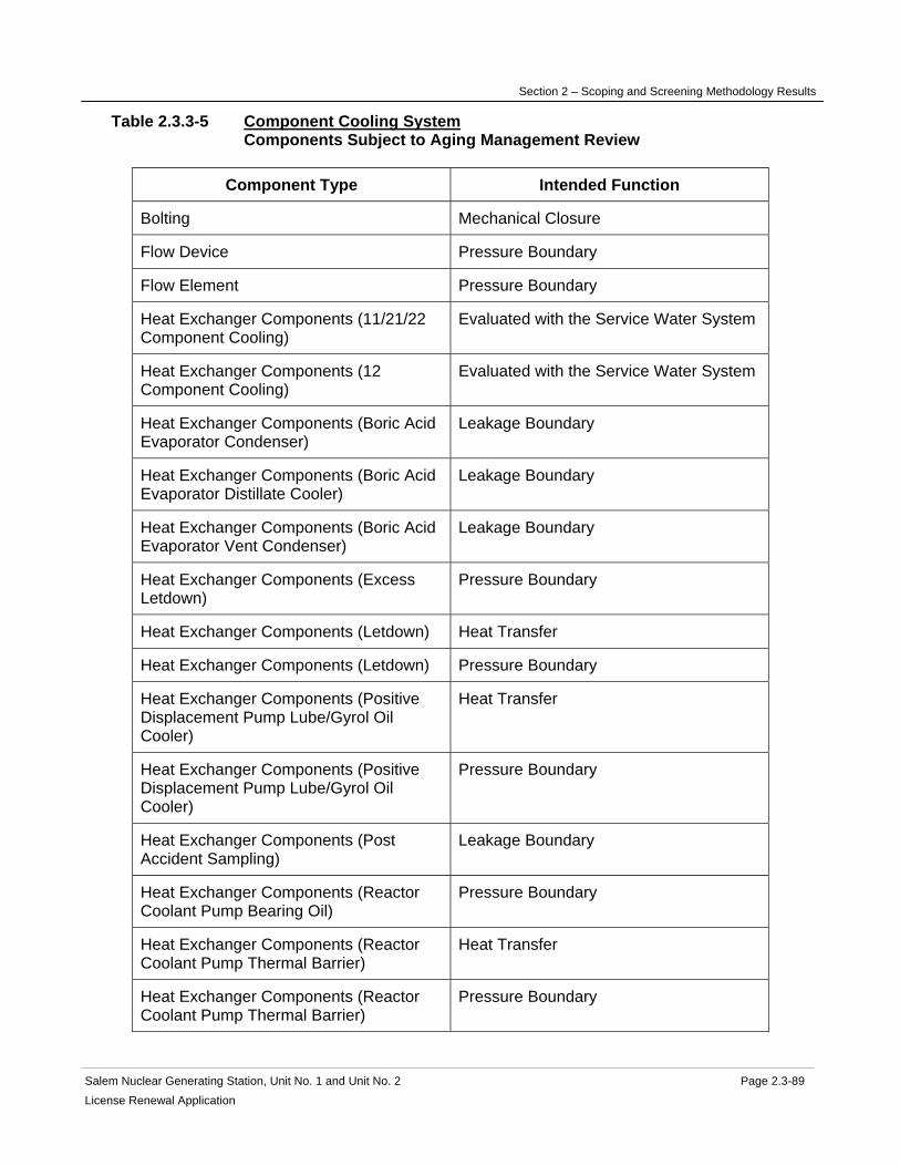
Section 2 – Scoping and Screening Methodology Results
Salem Nuclear Generating Station, Unit No. 1 and Unit No. 2 Page 2.3-89 License Renewal Application
Table 2.3.3-5 Component Cooling System Components Subject to Aging Management Review
Component Type Intended Function
Bolting Mechanical Closure
Flow Device Pressure Boundary
Flow Element Pressure Boundary
Heat Exchanger Components (11/21/22 Component Cooling)
Evaluated with the Service Water System
Heat Exchanger Components (12 Component Cooling)
Evaluated with the Service Water System
Heat Exchanger Components (Boric Acid Evaporator Condenser)
Leakage Boundary
Heat Exchanger Components (Boric Acid Evaporator Distillate Cooler)
Leakage Boundary
Heat Exchanger Components (Boric Acid Evaporator Vent Condenser)
Leakage Boundary
Heat Exchanger Components (Excess Letdown)
Pressure Boundary
Heat Exchanger Components (Letdown) Heat Transfer
Heat Exchanger Components (Letdown) Pressure Boundary
Heat Exchanger Components (Positive Displacement Pump Lube/Gyrol Oil Cooler)
Heat Transfer
Heat Exchanger Components (Positive Displacement Pump Lube/Gyrol Oil Cooler)
Pressure Boundary
Heat Exchanger Components (Post Accident Sampling)
Leakage Boundary
Heat Exchanger Components (Reactor Coolant Pump Bearing Oil)
Pressure Boundary
Heat Exchanger Components (Reactor Coolant Pump Thermal Barrier)
Heat Transfer
Heat Exchanger Components (Reactor Coolant Pump Thermal Barrier)
Pressure Boundary

Section 2 – Scoping and Screening Methodology Results
Salem Nuclear Generating Station, Unit No. 1 and Unit No. 2 Page 2.3-90 License Renewal Application
Component Type Intended Function
Heat Exchanger Components (Residual Heat Removal)
Heat Transfer
Heat Exchanger Components (Residual Heat Removal)
Pressure Boundary
Heat Exchanger Components (Sample) Heat Transfer
Heat Exchanger Components (Sample) Pressure Boundary
Heat Exchanger Components (Seal Coolers-Charging/SI Pumps)
Heat Transfer
Heat Exchanger Components (Seal Coolers-Charging/SI Pumps)
Pressure Boundary
Heat Exchanger Components (Seal Coolers-RHR Pumps)
Heat Transfer
Heat Exchanger Components (Seal Coolers-RHR Pumps)
Pressure Boundary
Heat Exchanger Components (Seal Water)
Heat Transfer
Heat Exchanger Components (Seal Water)
Pressure Boundary
Heat Exchanger Components (Spent Fuel)
Heat Transfer
Heat Exchanger Components (Spent Fuel)
Pressure Boundary
Heat Exchanger Components (Waste Evaporator Sub Cooler)
Leakage Boundary
Heat Exchanger Components (Waste Evaporator Vent Condenser)
Leakage Boundary
Heat Exchanger Components (Waste Evaporator Vent Gas Cooler)
Leakage Boundary
Heat Exchanger Components (Waste Gas Compressors)
Pressure Boundary
Piping and Fittings Leakage Boundary
Piping and Fittings Pressure Boundary
Piping and Fittings Structural Support

Section 2 – Scoping and Screening Methodology Results
Salem Nuclear Generating Station, Unit No. 1 and Unit No. 2 Page 2.3-91 License Renewal Application
Component Type Intended Function
Pump Casing (Component Cooling) Pressure Boundary
Sensor Elements Pressure Boundary
Strainer Body Pressure Boundary
Tanks (Surge) Pressure Boundary
Thermowell Pressure Boundary
Valve Body Pressure Boundary The aging management review results for these components are provided in: Table 3.3.2-5 Component Cooling System Summary of Aging Management Evaluation
Section 2 – Scoping and Screening Methodology Results
Salem Nuclear Generating Station, Unit No. 1 and Unit No. 2 Page 2.3-92 License Renewal Application
2.3.3.6 Compressed Air System
System Purpose The Compressed Air System is a normally operating mechanical system that provides motive power for safety-related and nonsafety-related instrumentation, controls and equipment. The Compressed Air System also provides compressed air to service air connections throughout the plant, as well as providing a constant flow of penetration cooling air to hot pipe containment penetrations. The Compressed Air System consists of the following plant systems: the station air system and the control air system. The Compressed Air System is in scope for license renewal. However, portions of the Compressed Air System are not required to perform intended functions and are not in scope. The purpose of the Compressed Air System is to provide a continuous supply of compressed air at the appropriate pressure, temperature, flowrate and air quality, to support pneumatic instrumentation and controls, air operated plant and service equipment, and penetration cooling requirements for both units of the Salem Generating Station. The Compressed Air System must supply critical air users with redundant air sources such that the loss of an air header, compressor or other single failure will not result in the need to shut down the plant or compromise its operation. The system accomplishes this purpose by utilizing redundant nonsafety-related compressors, air receivers and associated piping and valves of the station air system, in conjunction with redundant safety-related emergency air compressors, air receivers, air dryers, and associated piping and valves of the control air system. The control air system is also backed up by a Station Blackout (SBO) emergency diesel driven air compressor that can be started and aligned to the control air system for events where AC power sources to the station air compressors and emergency air compressors are assumed unavailable. System Operation The station air system consists of three parallel station air compressors supplying two redundant station air headers. Each redundant station air header includes an associated station air receiver. The station air headers supply compressed air to service hose connections throughout the plant. The station air system also provides compressed air to the condensate polishing air dryers, which feed various condensate polishing instrument panels and valve actuators, and to the heating boiler house air dryers to support heating boiler operation and controls. The station air system also provides compressed air to the chemistry lab air dryers, and to various other nonsafety-related users including the steam generator blowdown system mixed bed ion exchangers, sewage ejectors, truck bay door air motor and Radwaste System components. The station air system provides compressed air to the containment pressure test connections, and also provides a continuous flow of air to hot pipe containment penetrations for penetration cooling. The station air system is the normal source of compressed air to the control air system. The control air system consists of two parallel and redundant control air headers (A and B). Each header provides a source of clean, dry air for both nonsafety and safety-related pneumatically operated instruments and control valves throughout the plant. The normal air supply to the control air system is provided by the station air compressors through the control air dryers. An emergency control air compressor and associated air dryer on each unit
Section 2 – Scoping and Screening Methodology Results
Salem Nuclear Generating Station, Unit No. 1 and Unit No. 2 Page 2.3-93 License Renewal Application
supplies a backup source of air to the safety-related equipment on its own unit and a redundant air header on the opposite unit. In addition, a Station Blackout emergency diesel-driven air compressor is available to maintain control air pressure in the event of a Loss of Off-site Power (LOOP) and a coincident failure of both the "C" emergency diesel generators and the emergency control air compressor on the non-blacked out Unit. The Service Water System supplies cooling water to the station air compressor intercoolers, aftercoolers and lube oil coolers. The Fresh Water System provides a backup supply of cooling water if service water is unavailable. The Chilled Water System supplies cooling water to the emergency control air compressors. The Service Water System provides a backup supply of cooling water if chilled water is unavailable from both units. Station air and control air headers pass through the containment and the associated piping and valves are part of the containment boundary. The station air containment penetrations are normally isolated by closed manual valves or blank flanges. The control air containment penetrations include containment isolation valves that automatically close on a containment isolation signal. For more detailed information, see UFSAR Section 9.3.1. System Boundary The Compressed Air System begins at the inlet to each of the three parallel station air compressors, and continues through the compressor stages, intercoolers and aftercoolers, and through the moisture separator at the outlet of each compressor, then continuing from the discharge of the three compressor trains to connections with the two parallel station air headers and associated station air receivers. The Compressed Air System continues through two station air headers and ends at various systems and service connections throughout the plant. The station air distribution headers provide a normal and backup supply to the penetration coolers, with the discharge from the penetration coolers routed to a vent header that discharges outdoors to atmosphere. The penetration cooler discharge piping is not in scope, as failure of this piping would not impact the penetration cooling function. The station air distribution headers also supply compressed air to the two redundant control air system headers. The emergency supply to each unit's control air system begins at the inlet to the emergency control air compressor, and continues through the low pressure stage, intercooler, high pressure stage, aftercooler and aftercooler moisture separator and then continues to the emergency control air dryer skid. The flowpath continues through the in-service dryer and downstream filter and then splits to supply the two redundant control air headers including associated control air header receivers. Also included in the system boundary is the piping that permits the emergency control air compressor from each unit to be aligned to supply the opposite unit. The control air headers supply various components and areas of the plant that require a redundant safety-related source of compressed air. The redundant control headers penetrate containment and supply various components inside containment including the power operated relief valve accumulators. Also included in the system boundary is the Station Blackout emergency diesel driven air compressor, beginning at the compressor air inlet filter and continuing through the compressor, air/oil separator, aftercooler and aftercooler moisture separator to the inlet to the station blackout air dryer skid. The flowpath continues through the dryers and afterfilter to the connection to the Unit 2 control air system downstream of the Unit 2 emergency control air compressor.

Section 2 – Scoping and Screening Methodology Results
Salem Nuclear Generating Station, Unit No. 1 and Unit No. 2 Page 2.3-94 License Renewal Application
All associated piping, components and instrumentation contained within the flow path described above are included in the system evaluation boundary. Also included in the license renewal scoping boundary of the Compressed Air System are those portions of nonsafety-related piping and equipment that extend beyond the safety-related/nonsafety-related interface up to the location of the first seismic anchor. Included in this boundary are components relied upon to preserve the structural support intended function of this portion of the system. For more information, refer to the license renewal boundary drawing for identification of this boundary, shown in red. Not included in the Compressed Air System license renewal scoping boundaries are the following interfacing systems, which are separately evaluated as license renewal systems: Service Water System Chilled Water System Fresh Water System Reason for Scope Determination The Compressed Air System meets 10 CFR 54.4(a)(1) because it is a safety-related system that is relied upon to remain functional during and following design basis events. It meets 10 CFR 54.4(a)(2) because failure of nonsafety-related portions of the system could prevent satisfactory accomplishment of function(s) identified for 10 CFR 54.4(a)(1). It also meets 10 CFR 54.4(a)(3) because it is relied upon in safety analyses or plant evaluations to perform a function that demonstrates compliance with the Commission's regulations for Fire Protection (10 CFR 50.48), Environmental Qualification (10 CFR 50.49) and Station Blackout (10 CFR 50.63). The Compressed Air System is not relied upon in any safety analyses or plant evaluations to perform a function that demonstrates compliance with the Commission's regulations for Pressurized Thermal Shock (10 CFR 50.61) or Anticipated Transient Without Scram (10 CFR 50.62). System Intended Functions 1. Provide primary containment boundary. The Compressed Air system includes piping that penetrates primary containment. The containment penetrations include containment isolation valves to assure that radioactive material is not inadvertently transferred out of the containment. 10 CFR 54.4(a)(1) 2. Provide power to safety-related components. The Compressed Air System provides a source of pressurized air for proper operation of safety-related air operated components. 10 CFR 54.4(a)(1) 3. Resist nonsafety-related SSC failure that could prevent satisfactory accomplishment of a safety-related function. Failure of nonsafety-related station air components associated with containment penetration cooling could result in degradation of the containment concrete structure due to elevated temperature, potentially degrading containment integrity. Nonsafety-related station air components are also required to maintain air pressure on the fuel pool gates inflatable seals. Portions of nonsafety-related Compressed Air System piping provides structural support to attached safety-related piping. 10 CFR 54.4(a)(2)
Section 2 – Scoping and Screening Methodology Results
Salem Nuclear Generating Station, Unit No. 1 and Unit No. 2 Page 2.3-95 License Renewal Application
4. Relied upon in safety analyses or plant evaluations to perform a function that demonstrates compliance with the Commission's regulations for Fire Protection (10 CFR 50.48). The Control Air System supplied from the Emergency Control Air Compressor is credited for fire safe shutdown. 10 CFR 54.4(a)(3) 5. Relied upon in safety analyses or plant evaluations to perform a function that demonstrates compliance with the Commission's regulations for Environmental Qualification (10 CFR 50.49). Solenoid valves and limit switches associated with Compressed Air System air operated containment isolation valves are included in the scope of the Salem Environmental Qualification Program. 10 CFR 54.4(a)(3) 6. Relied upon in safety analyses or plant evaluations to perform a function that demonstrates compliance with the Commission's regulations for Station Blackout (10 CFR 50.63). The Compressed Air System supports operation of dampers in the Control Room and Control Area Ventilation System. 10 CFR 54.4(a)(3) UFSAR References 9.3.1 License Renewal Boundary Drawings Unit 1: LR-205201 Sheet 1 LR-205217 Sheet 1 LR-205217 Sheet 2 LR-205217 Sheet 3 LR-205238 Sheet 2 LR-205242 Sheet 7 LR-205243 Sheet 1 LR-205243 Sheet 2 LR-205243 Sheet 3 LR-205247 Sheet 1 LR-205247 Sheet 2 LR-205247 Sheet 3 Unit 2: LR-205301 Sheet 1 LR-205317 Sheet 1 LR-205317 Sheet 2 LR-205338 Sheet 2 LR-205342 Sheet 7 LR-205343 Sheet 1 LR-205343 Sheet 2 LR-205347 Sheet 1 LR-205347 Sheet 2 LR-205347 Sheet 3 LR-604495 Sheet 1 Unit Common: None

Section 2 – Scoping and Screening Methodology Results
Salem Nuclear Generating Station, Unit No. 1 and Unit No. 2 Page 2.3-96 License Renewal Application
Table 2.3.3-6 Compressed Air System Components Subject to Aging Management Review
Component Type Intended Function
Accumulator Pressure Boundary
Bolting Mechanical Closure
Compressor Housing (ECAC Compressor)
Pressure Boundary
Compressor Housing (SAC Compressor) Pressure Boundary
Compressor Housing (SBO Compressor) Pressure Boundary
Drain Traps Pressure Boundary
Electric Heaters (SAC Lube Oil) Pressure Boundary
Filter Housing Pressure Boundary
Flow Element Pressure Boundary
Flow Element Structural Support
Heat Exchanger Components (ECAC Aftercooler)
Evaluated with the Chilled Water System
Heat Exchanger Components (ECAC Intercooler)
Evaluated with the Chilled Water System
Heat Exchanger Components (Penetration Coolers)
Heat Transfer
Heat Exchanger Components (Penetration Coolers)
Pressure Boundary
Heat Exchanger Components (SAC Aftercooler)
Evaluated with the Service Water System
Heat Exchanger Components (SAC Intercooler)
Evaluated with the Service Water System
Heat Exchanger Components (SAC Lube Oil Cooler)
Evaluated with the Service Water System
Heat Exchanger Components (SBO Aftercooler)
Heat Transfer
Heat Exchanger Components (SBO Aftercooler)
Pressure Boundary
Hoses Pressure Boundary

Section 2 – Scoping and Screening Methodology Results
Salem Nuclear Generating Station, Unit No. 1 and Unit No. 2 Page 2.3-97 License Renewal Application
Component Type Intended Function
Piping and Fittings Pressure Boundary
Piping and Fittings Structural Support
Pump Casing (SAC Aux Lube Oil) Pressure Boundary
Pump Casing (SAC Main Lube Oil) Pressure Boundary
Sight Glasses Pressure Boundary
Silencer/ Muffler Pressure Boundary
Spectacle Blinds Pressure Boundary
Strainer Body Pressure Boundary
Tanks (SAC Lube Oil Reservoir) Pressure Boundary
Tanks (SAC Moisture Separator) Pressure Boundary
Tanks (SBO Aftercooler Moisture Separator, ECAC Aftercooler Moisture Separator)
Pressure Boundary
Tanks (SBO Dryer, ECAC Dryer) Pressure Boundary
Tanks (Station Air Receiver, Control Air Receiver)
Pressure Boundary
Thermowell Pressure Boundary
Valve Body Pressure Boundary
Valve Body Structural Support The aging management review results for these components are provided in: Table 3.3.2-6 Compressed Air System Summary of Aging Management Evaluation

Section 2 – Scoping and Screening Methodology Results
Salem Nuclear Generating Station, Unit No. 1 and Unit No. 2 Page 2.3-98 License Renewal Application
2.3.3.7 Containment Ventilation System
System Purpose The Containment Ventilation System is a normally operating mechanical system designed to provide heat removal from containment during normal operations and design basis events. The Containment Ventilation System consists of the following plant systems: containment fan cooler system, reactor nozzle support ventilation system, reactor shield ventilation system, pressure - vacuum relief system, containment purge system, hydrogen recombiner system, containment iodine removal system, and control rod drive ventilation system. The following plant systems of the Containment Ventilation System are in scope for license renewal: containment fan coolers system, reactor nozzle support ventilation system, reactor shield ventilation system, hydrogen recombiner system, and parts of the pressure - vacuum relief system and containment purge system. The following plant systems of the Containment Ventilation System are not in scope for license renewal: control rod drive ventilation system and containment iodine removal system. The Containment Ventilation System has interfaces with several other systems and components that are not within the license renewal boundary of the Containment Ventilation System, and are evaluated separately. These include the Auxiliary Building Ventilation System, Fuel Handling Ventilation System and Service Water System. The purpose of the Containment Ventilation System is to provide air circulation and heat removal from the containment atmosphere to prevent overheating. The Containment Ventilation System accomplishes this purpose by using fans to circulate the containment air through coolers supplied with cooling water by the Service Water System and to force air through the reactor shield and nozzle support areas. Another purpose of the Containment Ventilation System is to provide isolation capability to maintain the integrity of the containment barrier. The Containment Ventilation System accomplishes this purpose by blank flanges or by automatic valves that close when required for containment isolation. Containment fan cooling is an engineered safeguard designed to operate during normal operations and design basis events. Containment fan cooling removes heat from the containment atmosphere to limit containment temperature and pressure during design basis events, and to control the average containment temperature during normal power operation. Containment fan cooling also filters particles from the air during normal and accident conditions. However, the filtering function is not credited in the accident analysis. Reactor nozzle support ventilation operates during normal operation to maintain the temperature of the concrete surfaces in contact with the structural steel that supports the reactor vessel. Reactor nozzle support ventilation maintains the strength of the concrete supporting the reactor vessel. The fans are powered from vital busses backed up by the Emergency Diesel Generator & Auxiliaries System to cool the concrete during a loss of offsite power. Reactor shield ventilation operates continuously during normal operation to cool the reactor shield and the neutron monitoring instrumentation cables in the reactor cavity. Reactor shield ventilation provides makeup flow to the reactor nozzle support ventilation and maintains the strength of the concrete supporting the reactor vessel. The fans are powered from vital busses backed up by the Emergency Diesel Generator & Auxiliaries System to provide reactor cavity cooling during a loss of offsite power.

Section 2 – Scoping and Screening Methodology Results
Salem Nuclear Generating Station, Unit No. 1 and Unit No. 2 Page 2.3-99 License Renewal Application
Pressure-vacuum relief is a normally isolated system that may be used during power and hot standby operations as required to maintain containment pressure. Pressure-vacuum relief provides a filtered flow path between the containment and the auxiliary building. Pressure-vacuum relief also provides a containment isolation function. Containment purge is used to purge the containment atmosphere during normal plant shutdown to minimize dose to operating personnel and is normally isolated. Containment purge uses one supply air penetration and one exhaust air penetration. Containment purge also provides a containment isolation function. The hydrogen recombiners are capable of maintaining post-accident hydrogen concentration in the containment below limit of flammability in air. The requirements for the hydrogen recombiners have been deleted based on Technical Specification Amendment numbers 281 and 264 to Facility Operating License numbers DPR-70 and DPR-75. However, the recombiners have not been removed. The intended function of the hydrogen recombiners for license renewal is to maintain structural integrity to preclude system interactions. For this reason, the two hydrogen recombiners mounted above containment fan coolers have been included in the scope of license renewal. This system is not required to operate to support license renewal intended functions, and is in scope for potential spatial interaction. Containment iodine removal removes gaseous iodine and particulate radioactivity from the containment atmosphere as required during normal operation using two iodine removal units. This function is not credited in the accident analysis. Control rod drive ventilation operates continuously during normal operation using fans in the integrated head assembly to remove heat from the control rod drive mechanisms. The Containment Ventilation System is controlled from the control room. Containment fan cooling, control rod drive ventilation, reactor nozzle support ventilation, and reactor shield ventilation are normally in service. The pressure - vacuum relief, containment purge, and containment iodine removal are placed in service manually. In the event of an accident, containment fan cooling automatically switches to accident mode, the pressure - vacuum relief and containment purge containment isolation valves automatically close and control rod drive ventilation, reactor nozzle support ventilation, reactor shield ventilation and containment iodine removal trip off. System Operation The Containment Ventilation System is comprised of the following plant systems: containment fan cooler system, reactor nozzle support ventilation system, reactor shield ventilation system, pressure - vacuum relief system, containment purge system, hydrogen recombiner system, containment iodine removal system, and control rod drive ventilation system. Containment fan coolers are comprised of a common duct distribution system, instrumentation, and controls and five fan cooling units, each including a fan, motor, motor heat exchanger, cooling coil, roughing filter, demister, absolute filter, and dampers. The normal air flow path is from the containment atmosphere through the inlet dampers to the roughing filters and cooling coil to the fan. The fan discharges through the outlet dampers to the ring duct which distributes the air throughout the containment. The accident mode air flow path is from the containment atmosphere through the inlet dampers to the demister to the

Section 2 – Scoping and Screening Methodology Results
Salem Nuclear Generating Station, Unit No. 1 and Unit No. 2 Page 2.3-100 License Renewal Application
HEPA filter and cooling coil to the fan and discharge through the outlet dampers to the ring duct to the containment. The cooling coils and motor coolers are supplied with cooling water by the Service Water System. Containment fan coolers are normally in operation, with the fans in high speed, controlled from the control room. In the event of an accident, the fan cooling units are automatically tripped and sequenced onto the diesel generators in the accident mode, with the fans in low speed. In the accident mode, the dampers isolate the flow path through the roughing filters and open the flow path through the demister and HEPA filter. A minimum of three containment fan coil units in operation with a single containment spray train is capable of maintaining the containment temperature and pressure below their design basis values under accident conditions. The Containment Spray System is evaluated separately for license renewal. Reactor nozzle support ventilation is comprised of four fans arranged in two identical subsystems each comprised of two fans (one spare) connected to common ductwork embedded in the reactor shield, and associated dampers, controls and instrumentation. The reactor nozzle support ventilation flow path is from the reactor cavity annulus to the reactor nozzle support ventilation ductwork to the fans, to the outlet damper to the containment atmosphere. One fan in each subsystem is normally operating and the second fan is in standby. Reactor nozzle support ventilation is manually controlled from the control room. It is tripped off in the event of an accident, but is sequenced onto the emergency diesel generators during a loss of off-site power. Reactor shield ventilation is comprised of two fans and associated dampers, controls and instrumentation. The reactor shield ventilation flow path is from the containment ring duct to the inlet dampers to the fans to the outlet dampers and discharges to the incore instrument access room. One fan is normally in service and the other is in standby. Reactor shield ventilation is manually controlled from the control room. It is tripped off in the event of an accident, but is sequenced onto the emergency diesel generators during a loss of off-site power. Pressure-vacuum relief is comprised of valves, dampers, ductwork, roughing filters, a HEPA filter, a charcoal filter and associated instruments and controls. It is controlled from the control room and may be used during power and hot standby operations as required to maintain containment pressure. In the event of an accident the inboard and outboard containment isolation valves, vacuum relief unit outlet dampers and pressure relief unit outlet dampers automatically go closed. The vacuum relief flow path is from the Auxiliary Building atmosphere through the roughing filter, backdraft dampers and penetration isolation dampers into the containment atmosphere. The pressure relief flow path is from the containment atmosphere through penetration isolation dampers, a roughing filter, a HEPA filter, a charcoal filter, a backdraft damper and out through the Fuel Handling Ventilation System to the Auxiliary Building Ventilation System to the plant vent for release to the environment. Pressure differentials drive the air flow and fan power is not required. The valves and dampers are automatically closed on an isolation signal from the Reactor Protection System. Containment purge is comprised of penetration isolation valves, ductwork, and associated instruments and controls. It is normally isolated. It is put into service during normal plant shutdown and uses the Auxiliary Building Ventilation System to move and filter air for purge supply and exhaust. The containment purge supply flow path is from the Auxiliary Building Ventilation System through penetration dampers into the containment. The containment purge exhaust flow path is from the containment through penetration dampers into the Auxiliary

Section 2 – Scoping and Screening Methodology Results
Salem Nuclear Generating Station, Unit No. 1 and Unit No. 2 Page 2.3-101 License Renewal Application
Building Ventilation System. On Salem Unit 2, the inboard and outboard penetration isolation valves close automatically in the event of an accident. On Salem Unit 1, the inboard penetration isolation valves have been removed and blind flanges are installed inside containment during modes 1 through 4 and are only removed during modes 5 and 6, and the outboard penetration isolation valves close automatically in the event of an accident. Hydrogen recombiners are comprised of two hydrogen recombiners, each with a chimney enclosure and a catalyzed electrical heater and mounted on top of a containment fan cooling unit. The air flow path is through the inlet louvers, preheater section, orifice plate, heater section, mixing chamber, and exhaust louvers back into the containment. Hydrogen recombiners may be placed in service by the control room if required following an accident. Containment iodine removal is comprised of two iodine removal units, each with a roughing filter, a HEPA filter, and a charcoal filter, two fans and associated ductwork, dampers, controls and instrumentation. The iodine removal flow path is from the containment ring duct to the roughing filter, HEPA filter, and charcoal filter, to the fan which discharges to the containment atmosphere. Containment iodine removal is placed in service from the control room when required to remove gaseous iodine and particulate radioactivity from the containment atmosphere and it is automatically tripped in the event of an accident. Control rod drive ventilation is comprised of three control rod drive vent fans and associated ductwork, dampers, controls and instrumentation. The control rod drive ventilation flow path is from the integrated head assembly through the control rod drive ventilation ducts to the control rod drive vent fans, backdraft dampers and discharge to the containment atmosphere. Control rod drive ventilation operates continuously during normal operation to remove heat from the control rod drive mechanisms. Two fans are normally in service with one in standby. They are tripped in the event of an accident. For more detailed information, see UFSAR Sections 6.2 and 9.4.4. System Boundary The Containment Ventilation System begins at the inlet dampers to the five containment fan coil units and continues through the roughing filter inlets to the cooling coils and the fans and into the ring duct that distributes the air through the containment. The Containment Ventilation System terminates at the outlets from the ring duct into the containment. Also included is the accident flow path from the inlet dampers to the five containment fan coil units through the demister and absolute filter to the cooling coils and the fans. The Containment Ventilation System also includes reactor nozzle support ventilation, which begins at ductwork embedded in the reactor shield and continues to the reactor nozzle support fans and terminates at the fans outlet damper. The Containment Ventilation System also includes reactor shield ventilation, which begins at the connection with the ring duct and continues through the inlet damper to the reactor shield vent fan to the outlet damper and terminates at the ductwork into the incore instrument access room. The Containment Ventilation System also includes containment purge supply that begins at the flex connection downstream of the fire damper outlet from the Auxiliary Building Ventilation

Section 2 – Scoping and Screening Methodology Results
Salem Nuclear Generating Station, Unit No. 1 and Unit No. 2 Page 2.3-102 License Renewal Application
System and continues through an outboard isolation valve, through the containment wall and terminates at the inboard isolation valve. Also included is containment purge exhaust that begins at the inboard isolation valve, continues through the containment wall to the outboard isolation valve and terminates at the fire damper inlet to the Auxiliary Building Ventilation System. On Salem Unit 2, the inboard and outboard penetration isolation valves close automatically in the event of an accident. On Salem Unit 1, the inboard penetration isolation valves have been removed and blind flanges are installed inside containment during modes 1 through 4 and are only removed during modes 5 and 6, and the outboard penetration isolation valves close automatically in the event of an accident. The Containment Ventilation System also includes pressure-vacuum relief beginning at the inboard isolation valve and continuing through the containment wall to the outboard isolation valve then continuing to the pressure relief unit (roughing filter, HEPA filter, charcoal filter and outlet damper) and terminating at the backdraft damper that connects with the Fuel Handling Ventilation System. Also included is the ventilation flowpath through the backdraft damper to the vacuum relief unit (outlet damper and roughing filter). The vacuum relief unit is not in scope for license renewal. It is not relied upon in the accident analysis and is automatically isolated in the event of an accident. Also included are the two hydrogen recombiners, independent units mounted on top of the containment fan cooling units. The hydrogen recombiner boundary begins at the inlet louvers, continues through the preheater section, orifice plate, heater section, and mixing chamber, and ends at the exhaust louvers that discharge back into the containment. All associated ductwork, piping, components and instrumentation contained within the flow paths described above are included in the system evaluation boundary. The iodine removal units and their associated ductwork and instrumentation do not support an intended function and are not in scope for license renewal. The iodine removal unit fans are manually energized during normal operation to reduce the radioactivity within containment. They are tripped off in the event of an accident. The iodine removal units are isolated structurally from the remainder of the Containment Ventilation System by a flexible connection. The control rod drive ventilation fans and their associated ductwork and instrumentation do not support an intended function and are not in scope for license renewal. The control rod drive ventilation fans are normally in operation and are tripped off in the event of an accident. The control rod drive ventilation fans and their associated ductwork and instrumentation are not connected physically with the in scope portions of the Containment Ventilation System. Not included in the Containment Ventilation System license renewal scoping boundaries are the following interfacing systems, which are separately evaluated as license renewal systems: Auxiliary Building Ventilation System Compressed Air System Fuel Handling Ventilation System Service Water System

Section 2 – Scoping and Screening Methodology Results
Salem Nuclear Generating Station, Unit No. 1 and Unit No. 2 Page 2.3-103 License Renewal Application
Reason for Scope Determination The Containment Ventilation System meets 10 CFR 54.4(a)(1) because it is a safety-related system that is relied upon to remain functional during and following design basis events. It meets 10 CFR 54.4(a)(2) because failure of nonsafety-related portions of the system could prevent satisfactory accomplishment of function(s) identified for 10 CFR 54.4(a)(1). It also meets 10 CFR 54.4(a)(3) because it is relied upon in the safety analyses or plant evaluations to perform a function that demonstrates compliance with the Commission's regulation for Fire Protection (10 CFR 50.48) and Environmental Qualification (10 CFR 50.49). The Containment Ventilation System is not relied upon in any safety analyses or plant evaluations to perform a function that demonstrates compliance with the Commission's regulations for Pressurized Thermal Shock (10 CFR 50.61), Anticipated Transient Without Scram (10 CFR 50.62), or Station Blackout (10 CFR 50.63). System Intended Functions 1. Provide heat removal from primary containment and provide primary containment pressure control. The containment fan coolers are designed to recirculate and cool the containment atmosphere in the event of a LOCA and thereby ensure that the containment pressure will not exceed its design value. 10 CFR 54.4 (a)(1) 2. Provide removal of radioactive material from the primary containment atmosphere. The containment fan cooling system provides mixing of the post-accident containment atmosphere to allow the Containment Spray System to remove radioactive iodine. 10 CFR 54.4 (a)(1) 3. Provide primary containment boundary. The pressure-vacuum relief system and the containment purge system contain isolation valves and blank flanges used for isolation. 10 CFR 54.4 (a)(1) 4. Maintain emergency temperature limits within areas containing safety-related components. The containment fan cooling system is designed to recirculate and cool the containment atmosphere in the event of a LOCA and thereby ensure that the containment pressure will not exceed its design value. 10 CFR 54.4 (a)(1) 5. Resist nonsafety-related SSC failure that could prevent satisfactory accomplishment of a safety-related function. The reactor nozzle support fans maintain concrete surfaces in contact with the structural steel supports below the design temperature. 10 CFR 54.4 (a)(2) 6. Relied upon in safety analyses or plant evaluations to perform a function that demonstrates compliance with the Commission's regulations for Fire Protection (10 CFR 50.48). Ventilation Systems, which serve potentially radioactive areas (including the Containment) have provisions for monitoring airborne radioactivity and the capability to filter the discharged air through HEPA and charcoal bed filters. 10 CFR 54.4 (a)(3) 7. Relied upon in safety analyses or plant evaluations to perform a function that demonstrates compliance with the Commission's regulations for Environmental Qualification (10 CFR 50.49). Each of the isolation valves is designed to withstand the effects of any LOCA accident. 10 CFR 54.4 (a)(3)

Section 2 – Scoping and Screening Methodology Results
Salem Nuclear Generating Station, Unit No. 1 and Unit No. 2 Page 2.3-104 License Renewal Application
UFSAR References 9.4.4 6.2 License Renewal Boundary Drawings Unit 1: LR-205237 Sheet 1 LR-205238 Sheet 1 LR-205238 Sheet 2 LR-205238 Sheet 3 Unit 2: LR-205337 Sheet 1 LR-205338 Sheet 1 LR-205338 Sheet 2 LR-205338 Sheet 3 Unit Common: None

Section 2 – Scoping and Screening Methodology Results
Salem Nuclear Generating Station, Unit No. 1 and Unit No. 2 Page 2.3-105 License Renewal Application
Table 2.3.3-7 Containment Ventilation System Components Subject to Aging Management Review
Component Type Intended Function
Bolting Mechanical Closure
Damper Housing Pressure Boundary
Door Seals Pressure Boundary
Ducting and Components Pressure Boundary
Fan Housing Pressure Boundary
Filter Housing Pressure Boundary
Flexible Connection Pressure Boundary
Heat Exchanger Components (Fan Coil Motor Cooling HX)
Evaluated with the Service Water System
Heat Exchanger Components (Fan Coil Unit Coolers)
Evaluated with the Service Water System
Piping and Fittings Pressure Boundary
Valve Body Pressure Boundary The aging management review results for these components are provided in: Table 3.3.2-7 Containment Ventilation System Summary of Aging Management Evaluation

Section 2 – Scoping and Screening Methodology Results
Salem Nuclear Generating Station, Unit No. 1 and Unit No. 2 Page 2.3-106License Renewal Application
2.3.3.8 Control Area Ventilation System
System Purpose The Control Area Ventilation System is a normally operating mechanical system designed to maintain room temperatures, humidity and habitability of the control room envelope and control room areas under normal and design bases accident conditions. The Control Area Ventilation System consists of the following plant systems: the control area air conditioning system and the control room emergency air conditioning system. Both control area air conditioning and control room emergency air conditioning are in scope for license renewal. However, portions of the Control Area Ventilation System are not required to perform intended functions and are not in scope. The Control Area Ventilation System has several interfaces with other systems that are not in the license renewal boundary of Control Area Ventilation System. The purpose of control area air conditioning is to provide clean, filtered air at satisfactory temperature and humidity to the control room envelope and the control room area. Control area air conditioning accomplishes this purpose by recirculating air from the control room area, mixing it with filtered outside air, and running it through a multi-zone air conditioning unit supplied with heating water and chilled water. A small portion of air is discharged to the atmosphere through the discharge louver penthouse. The purpose of control room emergency air conditioning is to ensure uninterrupted safe occupancy of the control room envelope under emergency conditions by filtering airborne radioactive particles and maintaining the control room envelope at a positive differential pressure. Control room emergency air conditioning accomplishes this purpose by mixing outside air with recirculated air, passing it through a filter bank and cooler and distributing it throughout the control room envelope. The Control Area Ventilation System has other alignments of control area air conditioning and control room emergency air conditioning to cope with airborne toxic gas, hazardous chemical release, and fire inside or outside the control room envelope. Another purpose of the Control Area Ventilation System is to purge the control room in the event of fire or smoke generated in the control room. To accomplish this purpose control area air conditioning is placed on full intake air and all exhaust is expelled to the outside. Roughing filters are used for filtering the outside air. There is no recirculation. Control room emergency air conditioning is isolated and in standby. This mode is initiated manually by the control room operators. Another purpose of the Control Area Ventilation System is to totally isolate the control room envelope in the event of airborne toxic gas, hazardous chemical releases, or smoke outside the control room envelope. To accomplish this purpose, the normal intakes, emergency intakes and exhaust dampers are closed isolating the ventilation systems from the outside environment. Control area air conditioning is isolated by dampers from the control room envelope and operates in the full recirculation mode supplying cool air to the relay and equipment rooms, while control room emergency air conditioning recirculates the air in the control room envelope. Recirculated air to the control room envelope passes through a cooling coil and high efficiency particulate air (HEPA) and charcoal filter banks. This mode is initiated manually by the control room operators.

Section 2 – Scoping and Screening Methodology Results
Salem Nuclear Generating Station, Unit No. 1 and Unit No. 2 Page 2.3-107License Renewal Application
The Control Area Ventilation System also provides ventilation, hydrogen removal and temperature control for the battery rooms. The Control Area Ventilation System accomplishes this purpose using exhaust fans, inlet dampers, electrical heaters and ductwork. The battery room exhaust fans are normally in service and are controlled manually from the control room. The battery room exhaust fans trip off in the event of a safety injection signal, high radiation signal, or relay room halon discharge. The Control Area Ventilation System also provides ventilation and temperature control for the SRO office and work control center area. The Control Area Ventilation System accomplishes this purpose using a roughing filter, heating coil, cooling coil, supply fan and ductwork. The Control Area Ventilation System also provides ventilation for the elevator shaft, toilet room and janitor's closet. The Control Area Ventilation System accomplishes this purpose using exhaust fans and ductwork. These fans are normally in service and are manually controlled. The Control Area Ventilation System is normally operating with control area air conditioning in service. Control room emergency air conditioning is normally in standby and is activated automatically on receipt of a safety injection or control room intake high radiation signal. System Operation Control area air conditioning is comprised of outside air intakes, a filter enclosure equipped with three trains of roughing and medium efficiency filters, three supply fans (one standby), a multi-zone air conditioning unit with three cooling coils and one heating coil, air supply and return ductwork, dampers and controls. Control area air conditioning is normally in service. Control area air conditioning flows from the outside air intake through a roll-type roughing filter, a medium-efficiency filter, a supply fan, the multi-zone air conditioning unit, and distribution ductwork that supplies the control room envelope and control room area. Control area air conditioning also recirculates air from returns within the control room envelope and control room area to the inlet plenum of the filter enclosures. The heating coils in the multi-zone air conditioning unit are supplied with heating water from the Heating Water and Heating Steam System. The cooling coils in the multi-zone air conditioning unit are supplied with chilled water from the Chilled Water System. One or two of the three fans are normally in service with the third in standby. Each of the fans is supplied through its own filter train. The control area relay room is protected from fire by a halon system. Control area air conditioning to the control area relay room ventilation isolates in the event of a halon discharge. Control room emergency air conditioning is comprised of outside air intakes, a filter enclosure equipped with roughing, HEPA and charcoal filters, a cooling coil, two supply fans (one in standby), air supply and return ductwork, dampers and controls. Control room emergency air conditioning flows from the emergency air conditioning system control room returns to the emergency air filtration unit, consisting of a roughing filter, HEPA filter and charcoal filter, to the cooling coils, to the suction of the emergency air conditioning supply fans. Flow continues through the emergency air conditioning supply fans, to the distribution plenum, on to ductwork that distributes air into the control room envelope. Outside air also flows to control room emergency air conditioning from the outside air intakes to the inlet of the emergency air filtration unit. The cooling coils are supplied with chilled water from the Chilled Water System.
Section 2 – Scoping and Screening Methodology Results
Salem Nuclear Generating Station, Unit No. 1 and Unit No. 2 Page 2.3-108 License Renewal Application
Control room emergency air conditioning is initiated by a safety injection or control room intake high radiation signal on either unit. The control room envelope is isolated from control area air conditioning flow when control room emergency air conditioning is initiated. The Control Area Ventilation System has other alignments of control area air conditioning and control room emergency air conditioning to cope with airborne toxic gas, hazardous chemical release, and fire inside or outside the control room envelope. For fire or smoke generated inside the control room envelope, control area air conditioning flows from the outside air intake through a roll type roughing filter, a medium-efficiency filter, a supply fan, the multi-zone air conditioning unit, and distribution ductwork into the control room envelope and control room area. Exhaust air flows from the return air ducts in the control room envelope and the control room area and continues through ductwork to be expelled from the discharge louver penthouse on the top of the Auxiliary Building. There is no recirculation. Control room emergency air conditioning is isolated and in standby. For airborne toxic gas, hazardous chemical releases, or smoke outside the control room envelope, all of the normal intakes, emergency intakes and exhaust dampers are closed isolating the ventilation systems from the outside environment. Control area air conditioning flows from the returns within the relay and equipment rooms to the inlet plenum of the filter enclosures, through a roll type roughing filter, a medium-efficiency filter, a supply fan, the multi-zone air conditioning unit, and distribution ductwork to the relay and equipment rooms. Control room emergency air conditioning flows from the control room emergency air conditioning returns in the control room envelope and continues to the emergency air filtration unit (roughing filter, absolute filter and charcoal filter) to the cooling coils, to the emergency air conditioning supply fans, to the distribution plenum, to ductwork that distributes air into the control room envelope. This mode is manually initiated by the control room operators. The Control Area Ventilation System also provides ventilation, hydrogen removal and temperature control for the battery rooms using exhaust fans, inlet dampers, electrical heaters and ductwork. The battery room exhaust fans are normally in service and are controlled manually from the control room. The battery room exhaust fans trip off in the event of a safety injection signal, high radiation signal, or relay room halon discharge. The battery room ventilation is in scope for license renewal. The Control Area Ventilation System also provides ventilation for the SRO office and work control center area using a roughing filter, heating coil, cooling coil, supply fan and ductwork. The heating coil is heated by the Heating Water and Heating Steam System. The cooling coil is supplied with chilled water from the Chilled Water System. The Control Area Ventilation System also provides ventilation for the elevator shaft, toilet room and janitor's closet using exhaust fans and ductwork. These fans are normally in service and are manually controlled. These portions of the Control Area Ventilation System are not in scope for license renewal, however the toilet room exhaust damper forms part of the control area boundary and is in scope for license renewal. For more detailed information, see UFSAR Sections 6.4.1 and 9.4.1.
Section 2 – Scoping and Screening Methodology Results
Salem Nuclear Generating Station, Unit No. 1 and Unit No. 2 Page 2.3-109License Renewal Application
System Boundary The Control Area Ventilation System control area air conditioning begins at the control area air conditioning outside air intake and continues through the filter unit (roll type roughing filter and medium-efficiency filter) to the supply fans, to the multi-zone air conditioning unit, and continues through the distribution ductwork that terminates at the control room envelope and the control room area. Also included is the return flow path that begins at the return air ducts in the control room envelope and the control room area and continues through ductwork to terminate at the inlet to the filter unit. Also included is the exhaust flow path that begins at the return air duct and continues to the discharge louver penthouse on the top of the auxiliary building. The multi-zone air conditioning unit cooling coils are evaluated with the Chilled Water System. The multi-zone air conditioning unit heating coils are evaluated with the Heating Water and Heating Steam System. The Control Area Ventilation System control room emergency air conditioning begins at the control room emergency air conditioning returns and continues to the emergency air filtration unit (roughing filter, absolute filter and charcoal filter) to the cooling coils, to the emergency air conditioning supply fans, to the distribution plenum, to ductwork that distributes air into the control room envelope. Also included is the outside air flowpath from the outside air intakes to the inlet of the emergency air filtration unit. The control room emergency air conditioning cooling coils and their housing are evaluated with the Chilled Water System. Also included in the Control Area Ventilation System are the battery room supply flowpaths beginning at the dampers in the relay room and continuing through ductwork to terminate at the dampers in the battery rooms, and the louvered doors into the other battery rooms. Also included are the battery room exhaust flowpaths beginning at the ductwork in the battery rooms and continuing through the exhaust fans to the discharge on the top of the Auxiliary Building. Also included in the Control Area Ventilation System are the elevator shaft exhaust fan and the toilet room exhaust fan and damper. All associated piping, ductwork, components and instrumentation contained within the flow paths described above are included in the license renewal boundary. Not in scope for license renewal is the ventilation for the SRO office and work control center area including the roughing filter, heating coil, cooling coil, and supply fan on top of the Auxiliary Building and its distribution ductwork. Also not in scope for license renewal is the ductwork leading from the toilet room and janitor's closet to the toilet exhaust fan. These components perform no intended function and are not within an area in proximity of components performing a safety-related function. Not included in the license renewal boundary for the Control Area Ventilation System is the ventilation for the SRO office and work control center area, the exhaust ductwork leading from the toilet room and janitor's closet to the toilet exhaust fan. Also not included are the cooling coils in the control room emergency air conditioning and the heating and cooling coils in the control area air conditioning multi-zone air conditioning unit. Not included in the Control Area Ventilation System license renewal scoping boundaries are the following interfacing systems, which are separately evaluated as license renewal systems:
Section 2 – Scoping and Screening Methodology Results
Salem Nuclear Generating Station, Unit No. 1 and Unit No. 2 Page 2.3-110 License Renewal Application
Chilled Water System Fire Protection System Heating Water and Heating Steam System Reason for Scope Determination The Control Area Ventilation System meets 10 CFR 54.4(a)(1) because it is a safety-related system that is relied upon to remain functional during and following design basis events. It meets 10 CFR 54.4(a)(2) because failure of nonsafety-related portions of the system could prevent satisfactory accomplishment of function(s) identified for 10 CFR 54.4(a)(1). It also meets 10 CFR 54.4(a)(3) because it is relied upon in the safety analyses or plant evaluations to perform a function that demonstrates compliance with the Commission's regulations for Fire Protection (10 CFR 50.48) and Station Blackout (10 CFR 50.63). The Control Area Ventilation System is not relied upon in any safety analyses or plant evaluations to perform a function that demonstrates compliance with the Commission's regulation for Environmental Qualification (10 CFR 50.49), Pressurized Thermal Shock (10 CFR 50.61), or Anticipated Transients Without Scram (10 CFR 50.62). System Intended Functions 1. Provide centralized area for control and monitoring of nuclear safety-related equipment. The control area air conditioning system and the control room emergency air conditioning system are designed to maintain room temperatures within limits required for operation, maintenance and testing of plant controls, and permits continuous occupancy under normal and design accident conditions. 10 CFR 54.4(a)(1) 2. Maintain emergency temperature limits within areas containing safety-related components. The control area air conditioning system and the control room emergency air conditioning system are designed to maintain room temperatures within limits required for operation, maintenance and testing of plant controls, and permits continuous occupancy under normal and design accident conditions. 10 CFR 54.4(a)(1) 3. Resist nonsafety-related SSC failure that could prevent satisfactory accomplishment of a safety-related function. The Control Area Ventilation System maintains ambient temperatures in the control room and adjoining equipment room for personnel comfort and instrument accuracy; in the Relay Room and Unit 2 125 VDC Battery Rooms; and in the Unit 1 125 VDC Battery Rooms during normal plant operating conditions. The toilet exhaust fan automatically shuts down upon detection of control room intake high radiation or a safety injection signal to maintain a positive pressure in the control room following a loss of coolant accident. 10 CFR 54.4(a)(2) 4. Relied upon in safety analyses or plant evaluations to perform a function that demonstrates compliance with the Commission's regulations for Fire Protection (10 CFR 50.48). The Control Area Ventilation System provides smoke and heat venting for the control room, battery room and relay room. 10 CFR 54.4(a)(3) 5. Relied upon in safety analyses or plant evaluations to perform a function that demonstrates compliance with the Commission's regulations for Station Blackout (10 CFR 50.63). The Control Area Ventilation System maintains ambient conditions in the control room area in the event of a station black out. 10 CFR 54.4(a)(3)

Section 2 – Scoping and Screening Methodology Results
Salem Nuclear Generating Station, Unit No. 1 and Unit No. 2 Page 2.3-111License Renewal Application
UFSAR References 6.4.1 9.4.1 License Renewal Boundary Drawings Unit 1: LR-205248 Sheet 2 Unit 2: LR-205348 Sheet 2 Unit Common: None

Section 2 – Scoping and Screening Methodology Results
Salem Nuclear Generating Station, Unit No. 1 and Unit No. 2 Page 2.3-112License Renewal Application
Table 2.3.3-8 Control Area Ventilation System Components Subject to Aging Management Review
Component Type Intended Function
Bird Screen Filter
Bolting Mechanical Closure
Damper Housing Pressure Boundary
Door Seals Pressure Boundary
Ducting and Components Pressure Boundary
Fan Housing Pressure Boundary
Filter Housing Pressure Boundary
Flexible Connection Pressure Boundary
Heat Exchanger Components (CAAC Heating Coils)
Evaluated with the Heating Water and Heating Steam System
Heat Exchanger Components (CAAC Unit Cooling Coils)
Evaluated with the Chilled Water System
Heat Exchanger Components (CREAC Unit Cooling Coils)
Evaluated with the Chilled Water System
Louver (Discharge Louver Penthouse) Pressure Boundary
Piping and Fittings Pressure Boundary
Sensor Elements Pressure Boundary
Valve Body Pressure Boundary The aging management review results for these components are provided in: Table 3.3.2-8 Control Area Ventilation System Summary of Aging Management Evaluation
Section 2 – Scoping and Screening Methodology Results
Salem Nuclear Generating Station, Unit No. 1 and Unit No. 2 Page 2.3-113 License Renewal Application
2.3.3.9 Cranes and Hoists
System Purpose Cranes and Hoists is comprised of load handling overhead bridge cranes, monorails, jib cranes, lifting devices, and hoists provided throughout the facility to support operation and maintenance activities. The system includes cranes, monorails and hoists required to comply with the requirements of NUREG-0612,"Control of Heavy Loads at Nuclear Power Plants", and hoists for handling light loads. Major cranes include the Polar Gantry Crane, Cask Handling Crane, Main Turbine Area Gantry Crane and Aux Turbine Area Crane, Solid Radwaste Overhead Crane, 90T Grove Crane and 900 Series American Crawler Crane. The Polar Gantry Crane services the operating floor and is used to lift heavy loads such as the reactor vessel integrated head, and upper and lower reactor vessel internals. The Solid Radwaste Overhead Crane is used to handle loads which include large (radwaste) casks. The 90T Grove Crane and 900 Series American Crawler Crane are used to handle loads including the service water bay roof hatch concrete cover plugs, service water pumps, service water strainers, and service water traveling screens. The Cask Handling Crane in the Fuel Handling Building handles new fuel and also spent fuel casks. The purpose of Cranes and Hoists is to safely move material and equipment as required to support operations and maintenance activities. The Cranes and Hoists accomplish this by compliance with NUREG-0612 and use of written procedures so damage resulting from a heavy load drop will not prevent safe shutdown of the reactor. Included in the evaluation boundary of Cranes and Hoists are a number of other load handling systems and smaller cranes and monorails in various areas of the facility. Cranes, monorails and hoists that are in scope of NUREG-0612 review are in scope for license renewal. Other cranes, monorails and hoists that are not in the scope of NUREG-0612 review but travel in the vicinity of safety-related systems, structures, and components (SSCs) are also in scope for license renewal, if it is determined that their failure may impact a safety-related function. As a result, the following cranes and hoists are in scope for license renewal: -Polar Gantry Crane (Containment Building) with Equipment Hatch Jib -Dome Service Bridge (Salem Unit 2 Only) -Reactor Vessel Head Stud Detensioner Monorails -Cask Handling Crane (Fuel Handling Building) -Spent Fuel Pool Gate Monorails (Fuel Handling Area Stop Log Gate Hoists) -Skimmer Filter Jib Crane -Steam Generator Drain and Blowdown Filter Hoist (SGDBF Hoist is not used and is directly above unused equipment but has not been classified as abandoned) -Demineralizer and Ion Exchanger Service Monorails -Spent Fuel Pit Filter Handling Monorails -Reactor Coolant Ion Exchanger and Filter Underhung Bridge Crane -Refueling Water Purification and Concentrate Filter Monorails -Seal Water Injection and Return Filter Monorails -Solid Radwaste Overhead Crane -Auxiliary Feedwater Pumps Monorails -Charging Pump Monorails

Section 2 – Scoping and Screening Methodology Results
Salem Nuclear Generating Station, Unit No. 1 and Unit No. 2 Page 2.3-114License Renewal Application
-Component Cooling Pump Monorails -Safety Injection Pump Monorails -Fuel Handling Skimmer Pump Hoist -Fuel Handling Rod Cluster Containment Changing Filter Hoist -Containment Spray Pump Monorails -RHR Pump Motor Monorails Serving El. 55 and El. 45 -18 T Grove Crane (Roof Aux. Building) -Service Water Strainers Monorails -Spent Fuel Pit Pump Monorails -Aux. Bldg Monorail above Waste Monitor Valve Pit -Boric Acid Evaporator Monorail -Liquid Waste Evaporator Monorail -Decontamination Room Overhead Crane -Diesel Generator Monorails -Boric Acid Batching Monorail -90T Grove Crane -900 Series American Crawler Crane. The boundary for Cranes and Hoists is limited to load bearing structural components such as, the bridge, trolley, rail system (rails, rail clips, and rail fasteners), structural bolts, lifting devices, monorail beams, and jib crane structural members. Cranes and Hoists that were determined not in scope for license renewal are: -Main Turbine Area Gantry Crane -Aux. Turbine Area Crane -Turbine Area Monorails, Trolley Beams -Service Building Monorails -'A' Building Hot Shop Crane -CVC Concentrate and Refueling Purification Hoists -CVC Seal Water Injection Filter Hoists -CVC Ion Exchanger Filter Hoists -Fish Counting House Screen Hoists -Circulating Water trash and Trough Gate Hoists -Reactor Cool No. 1 Containment Elevator -Reactor Cool Containment Portable Hoists -'B' Building Maintenance Shop Crane -Elevators in Aux Buildings, Control Areas, Service Buildings, Turbine Buildings, Sampling System Room Dumbwaiter; and miscellaneous small hoists in nonsafety-related structures. Failure of these cranes and hoists will not impact a safety-related intended function. Personnel lifts, pump up hydraulic lifts, small portable hoists, and two-man and one-man lifts are portable equipment and are not in scope for license renewal. Not included in the evaluation boundary of Cranes and Hoists are refueling equipment bridges, fuel transfer carriage hoist, overhead crane structural support steel, and crane runway girders. The refueling bridges and the fuel transfer hoists and associated equipment including: the Manipulator Crane, Fuel Handling Crane, Spent Fuel Upending Device, Containment Fuel Upending Device, New Fuel Elevator Winch, and Fuel Transfer System (Underwater Conveyor Car) are separately evaluated with the Fuel Handling and Fuel Storage System.

Section 2 – Scoping and Screening Methodology Results
Salem Nuclear Generating Station, Unit No. 1 and Unit No. 2 Page 2.3-115 License Renewal Application
The structural support steel and runway girders for all cranes and hoists are included with the structure serviced by the crane. For more detailed information, refer to UFSAR Sections 9.1.4, 9.1.5 and Table 9.1-4. System Operation Not Required. System Boundary Not Required. Reason for Scope Determination Cranes and Hoists meets 10 CFR 54.4(a)(1) because it is a safety-related system that is relied upon to remain functional during and following design basis events. It meets 10 CFR 54.4(a)(2) because failure of nonsafety-related portions of the system could prevent satisfactory accomplishment of function(s) identified for 10 CFR 54.4(a)(1). It does not meet 10 CFR 54.4(a)(3) because it is not relied upon in any safety analyses or plant evaluations to perform a function that demonstrates compliance with the Commission's regulations for Fire Protection (10 CFR 50.48), Environmental Qualification (10 CFR 50.49), Pressurized Thermal Shock (10 CFR 50.61), Anticipated Transient Without Scram (10 CFR 50.62), or Station Blackout (10 CFR 50.63). System Intended Functions 1. Provides physical support, shelter, and protection for safety-related systems, structures, and components (SSCs). The Polar Gantry Crane and the Steam Generator Drain and Blowdown Filter Hoist (SGDBF Hoist is not used and is directly above unused equipment) are classified safety-related, and the Containment Building Polar Gantry Cranes support load lifts and transport loads over irradiated fuel. 10 CFR 54.4(a)(1) 2. Provides a safe means for handling safety-related components and loads above or near safety-related components. The other in scope Cranes and Hoists also handle loads above or near safety-related components. 10 CFR 54.4(a)(2) UFSAR References 9.1.4 Table 9.1-4 9.1.5 License Renewal Boundary Drawings None
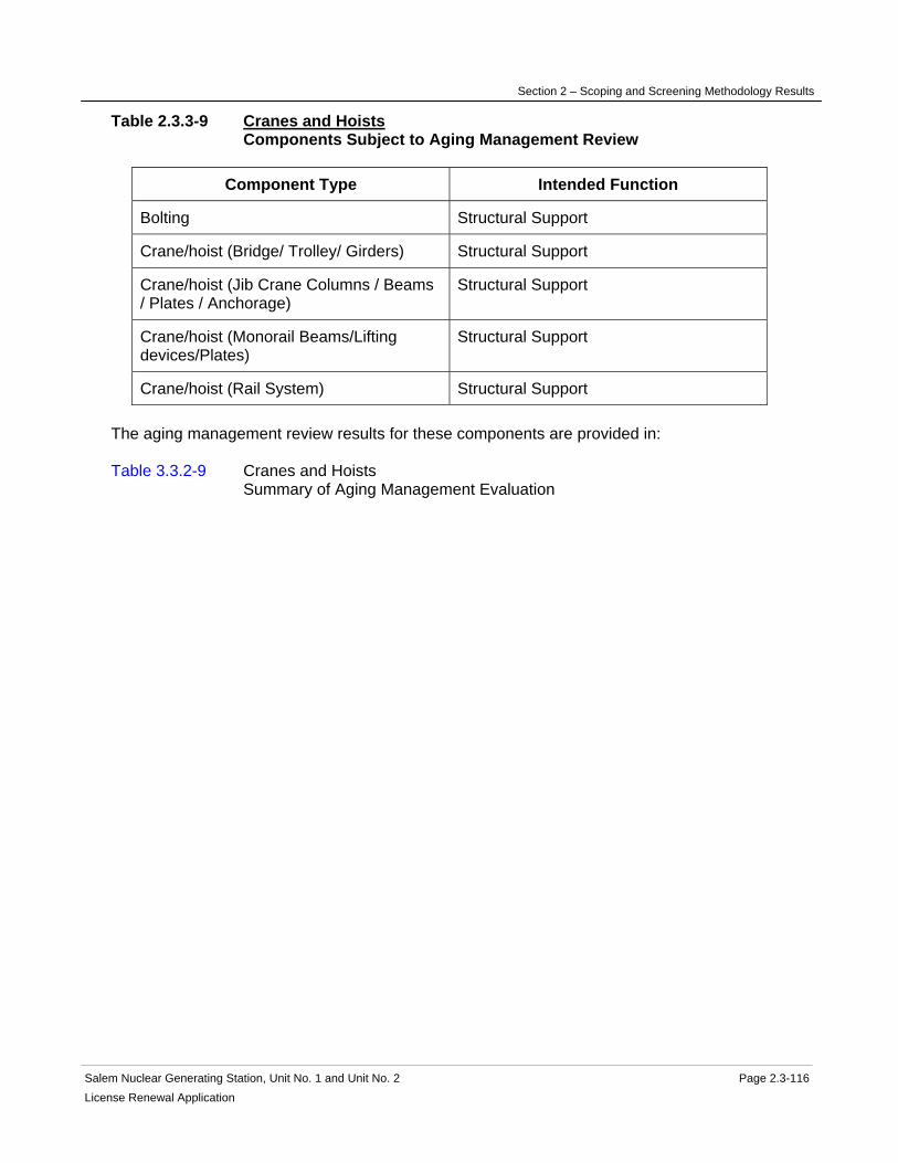
Section 2 – Scoping and Screening Methodology Results
Salem Nuclear Generating Station, Unit No. 1 and Unit No. 2 Page 2.3-116 License Renewal Application
Table 2.3.3-9 Cranes and Hoists Components Subject to Aging Management Review
Component Type Intended Function
Bolting Structural Support
Crane/hoist (Bridge/ Trolley/ Girders) Structural Support
Crane/hoist (Jib Crane Columns / Beams / Plates / Anchorage)
Structural Support
Crane/hoist (Monorail Beams/Lifting devices/Plates)
Structural Support
Crane/hoist (Rail System) Structural Support The aging management review results for these components are provided in: Table 3.3.2-9 Cranes and Hoists Summary of Aging Management Evaluation

Section 2 – Scoping and Screening Methodology Results
Salem Nuclear Generating Station, Unit No. 1 and Unit No. 2 Page 2.3-117 License Renewal Application
2.3.3.10 Demineralized Water System
System Purpose The Demineralized Water System is a normally operating system designed to purify both well water and recovered water from the condensers to high purity water standards for various uses. It is a common system for both Salem Units. The Demineralized Water System consists of the following plant systems: demineralized water make-up system and demineralized water-restricted areas system. The demineralized water make-up system consists of the following subsystems: demineralization process, and demineralized water storage and distribution. The Demineralized Water System is in scope for license renewal. It has interfaces with other license renewal systems. However, portions of the Demineralized Water System such as the demineralization process and portions of the storage and distribution subsystems are not required to perform intended functions and are not in scope. The Demineralized Water System has several interfaces with other systems that are not in the license renewal boundary of the Demineralized Water System. The purpose of the Demineralized Water System is to provide a source of demineralized water for various vital and non-vital uses, such as providing an alternate supply of demineralized water to the Auxiliary Feedwater System, providing make-up to the primary water storage tank, boric acid batching tanks, component cooling water surge tanks, chilled water expansion tanks, emergency diesel generator jacket water expansion tanks, stator cooling, spent fuel pool and the main condenser. It also provides a source of flushing water to the Safety Injection, Residual Heat Removal, condensate polisher, and the Steam Generators. The demineralized water-restricted areas system provides demineralized water to other systems and areas in the Auxiliary and Fuel Handling Building and the Containment Structure. Upon receiving a containment isolation signal, the demineralized water-restricted areas line entering containment is automatically isolated. Portions of the Demineralized Water System are also credited for Post Fire Safe Shutdown, specifically, the flow path from the demineralized water storage tanks through the auxiliary demineralized water transfer pump to the auxiliary feedwater storage tanks and to the suction of the auxiliary feedwater pumps, or both. The auxiliary demineralized water transfer pump is powered from a vital 460V bus. The Demineralized Water System accomplishes its purpose through collection of raw water, demineralization processes, storage tanks, heat exchangers, circulators, transfer pumps, and distribution piping, including valves and instrumentation. System Operation The Demineralized Water System consists of the demineralized process and demineralized water storage and distribution subsystems. The demineralization process subsystem is comprised of one raw water basin, raw water pumps and the Ecolochem water treatment plant. The vendor make-up plant uses reverse

Section 2 – Scoping and Screening Methodology Results
Salem Nuclear Generating Station, Unit No. 1 and Unit No. 2 Page 2.3-118 License Renewal Application
osmosis and other demineralization processes. The original make-up plant has components that have been abandoned in place, including the liquid-filled vacuum deaerator and the three (3) liquid-filled anion vessels, all of which are located in the Turbine Building. Failure of any of these four components would not constitute a leakage or spray hazard to any safety-related component. The demineralized water storage and distribution subsystem is comprised of two storage tanks, four transfer pumps, two heat exchangers and two circulators for maintaining water temperature, and the necessary piping, valves, instrumentation, and controls. The demineralized water-restricted areas system is comprised of the necessary piping, valves, instrumentation, and controls to provide demineralized water to use points in the Auxiliary and Fuel Handling Buildings, and the Containment Structure. The operators manually place the Ecolochem water treatment plant in service to maintain a desired level in the demineralized water storage tanks. The raw water pumps and/or the Fresh Water System pumps (back-up) provide a supply of water to the Ecolochem water treatment plant. The Ecolochem water treatment plant purifies the water through several processes, and pumps it to the demineralized water storage tanks. The demineralized water transfer pumps take suction from the demineralized water storage tanks, and discharge into a header. The demineralized water transfer pumps are automatically started by low pressure conditions in the discharge header, and also can be manually started on the control room console. System flow begins at the demineralized water storage tanks, through the transfer pumps, and into the main discharge header. From the main header, flow continues through branch piping and valves, and supplies demineralized water to each of the following locations: Air Removal Vacuum Pump Separator Tanks Auxiliary Feedwater at the Auxiliary Feedwater pumps' suction Auxiliary Feedwater Storage Tanks Chemical and Volume Control Boric Acid Batching Tanks Primary Water Storage Tanks Chemical Feed Auxiliary Feed pumps Chilled Water Expansion Tanks Component Cooling Surge Tanks Condensate Polishing Vessels Diesel Generators Jacket Water Expansion Tanks Main Generator Stator House Heating Boiler Superheaters, Make-Up, and Chemical Solution tanks Residual Heat Removal system Safety Injection system Sampling laboratory Spent Fuel Cooling Pool Steam Generator Drains and Blowdown Cation Vessels Steam Generator Feed and Condensate Main Condenser Waste Gas compressors Waste Liquid Waste Monitor Pumps The Demineralized Water System has demineralized water circulators that recirculate the demineralized water storage tank contents through the shell side of demineralized water heat exchangers heated by the Heating Water and Heating Steam System.

Section 2 – Scoping and Screening Methodology Results
Salem Nuclear Generating Station, Unit No. 1 and Unit No. 2 Page 2.3-119License Renewal Application
There is a recirculation line off of the transfer pump discharge header to maintain minimum flow in the system, based on a flow switch setpoint that opens the recirculation line valve. The open position of the recirculation line valve provides permission for operation of the auxiliary demineralized water transfer pump. This flowpath is credited in the Post Fire Safe Shutdown analysis. Demineralized water enters primary containment via the containment building outboard isolation valve and inboard isolation check valve. The containment building outboard isolation valve can be manually operated from the control room and is automatically closed upon a containment isolation signal from the Reactor Protection System. The Demineralized Water System has two storage tanks (each with its own heat exchanger and circulator), and shares the four transfer pumps. Only one tank and the auxiliary demineralized water transfer pump are required to make-up to the Auxiliary Feedwater System. The Ecolochem water treatment plant has a redundant process train. System Boundary The Demineralized Water System boundary begins at the demineralized water storage tanks and continues through the demineralized water transfer pumps and demineralized water auxiliary transfer pump into the demineralized water system discharge header and onto the demineralized water-restricted area portion of the Demineralized Water System boundary. The Demineralized Water System boundary terminates at both hose connections and hard pipe connections to the following locations that interface with systems in scope for license renewal: the auxiliary feedwater pumps' suction, and also at the auxiliary feedwater storage tanks that are part of the Auxiliary Feedwater System; boric acid batching tanks and the primary water storage tanks that are part of the Chemical and Volume Control System; surge tanks that are part of the Component Cooling System; expansion tanks that are part of the Diesel Generator and Auxiliaries System; superheater that is part of the Heating Water and Heating Steam System; flushing piping that is part of the Residual Heat Removal System; flushing piping that is part of the Safety Injection System; laboratory connections that are part of the Sampling System; spent fuel pool that is part of the Spent Fuel Cooling System; and the compressors and monitor pumps that are part of the Radwaste System. Also included in the Demineralized Water System boundary is the Demineralized Water transfer pumps' recirculation line where a portion of the forward flow is recirculated back to the suction piping. All associated piping, components, and instrumentation contained within the flow path described above are included in the Demineralized Water System evaluation boundary. The Demineralized Water System boundary terminates at isolation valves upstream of branches that interface with the following in scope systems; Main Condensate and Feedwater, Main Generator and Auxiliaries, Chilled Water, and Steam Generators. The Demineralized Water System boundary encompasses the liquid filled portions of the system that are located in proximity to equipment performing a safety-related function. This includes all of the demineralized water-restricted areas system located in the Auxiliary and Fuel Handling Buildings and the Containment Structure. Included in this boundary are pressure retaining components relied upon to preserve the leakage boundary intended function of the Demineralized Water System. For more information, refer to the license renewal boundary drawings for identification of this boundary, shown in red.
Section 2 – Scoping and Screening Methodology Results
Salem Nuclear Generating Station, Unit No. 1 and Unit No. 2 Page 2.3-120 License Renewal Application
The Demineralized Water System boundary also terminates at both hose connections and hard pipe connections to the following locations that interface with systems not in scope for license renewal: vacuum pump separator tanks that are part of the Main Condenser and Air Removal System, and the auxiliary chemical feed pumps that are part of the chemical feed system. Not included in the Demineralized Water boundary scope of license renewal are: the demineralization process contained in the vendor make-up plant that is located in the demineralized water treatment building (Yard Area), buried piping in the Yard Area, and distribution piping located in the Turbine Buildings and condensate polisher buildings that are outside of the flow path to the Auxiliary Feedwater System and the demineralized water-restricted areas system. These portions of the Demineralized Water System are not located in areas such that a Demineralized Water System failure would constitute a spray hazard to any safety related components. Components in these portions of the Demineralized Water System that are not required to support the system's leakage boundary intended functions are not included in the scope of license renewal. Not included in the Demineralized Water System scoping boundary are the following interfacing systems, which are separately evaluated as license renewal systems: Auxiliary Feedwater Chemical and Volume Control Chilled Water Component Cooling Diesel Generator & Auxiliaries Heating Water & Heating Steam Main Condensate Radwaste Residual Heat Removal Safety Injection Sampling Spent Fuel Cooling Steam Generators Reason for Scope Determination The Demineralized Water System meets 10 CFR 54.4(a)(1) because it is a safety-related system that is relied upon to remain functional during and following design basis events. It meets 10 CFR 54.4(a)(2) because failure of non-safety-related portions of the system could prevent satisfactory accomplishment of function(s) identified for 10 CFR 54.4(a)(1). It also meets 10 CFR 54.4(a)(3) because it is relied upon in the safety analyses or plant evaluations to perform a function that demonstrates compliance with the Commission's regulations for Fire Protection (10 CFR 50.48). The Demineralized Water System is not relied upon in any safety analyses or plant evaluations to perform a function that demonstrates compliance with the Commission's regulations for Environmental Qualification (10 CFR 50.49), Pressurized Thermal Shock (10 CFR 50.61), Anticipated Transient Without Scram (10 CFR 50.62), or Station Blackout (10 CFR 50.63).
Section 2 – Scoping and Screening Methodology Results
Salem Nuclear Generating Station, Unit No. 1 and Unit No. 2 Page 2.3-121License Renewal Application
System Intended Functions 1. Provide primary containment boundary. The Demineralized Water System has outboard and inboard containment isolation valves that isolate the demineralized water line penetrating primary containment. 10 CFR 54.4(a)(1) 2. Resist nonsafety-related SCC failure that could prevent satisfactory accomplishment of a safety-related function. The Demineralized Water System contains nonsafety-related water filled lines, both for hose connections and hard piping connections in the Auxiliary, Fuel Handling, and Containment Buildings that have the potential for spatial interactions with safety-related SCCs. The Demineralized Water System has a main flow path from the Demineralized Water Storage Tanks to the Auxiliary Feedwater System that includes piping in the Auxiliary Buildings. 10 CFR 54.4(a)(2) 3. Relied upon in safety analyses or plant evaluations to perform a function that demonstrates compliance with the Commission's regulations for Fire Protection (10 CFR 50.48). The Post Fire Safe Shutdown Analyses credit the Auxiliary Demineralized Water Transfer Pump and the minimum flow recirculation valve as a back-up source of demineralized water for the Auxiliary Feedwater System. 10 CFR 54.4(a)(3) UFSAR References 9.2.3 License Renewal Boundary Drawings Unit 1: LR-205202 Sheet 1 LR-205225 Sheet 1 LR-205228 Sheet 1 LR-205230 Sheet 1 LR-205231 Sheet 1 LR-205232 Sheet 1 LR-205232 Sheet 2 LR-205233 Sheet 1 LR-205234 Sheet 3 LR-205236 Sheet 1 LR-205339 Sheet 1 LR-205239 Sheet 4 LR-205241 Sheet 1 LR-205241 Sheet 2 LR-205241 Sheet 3 LR-205241 Sheet 4 LR-205241 Sheet 5 LR-205244 Sheet 2 LR-205246 Sheet 1 LR-205246 Sheet 2
Section 2 – Scoping and Screening Methodology Results
Salem Nuclear Generating Station, Unit No. 1 and Unit No. 2 Page 2.3-122 License Renewal Application
Unit 2: LR-205302 Sheet 1 LR-205315 Sheet 1 LR-205315 Sheet 2 LR-205325 Sheet 1 LR-205328 Sheet 1 LR-205330 Sheet 1 LR-205331 Sheet 1 LR-205332 Sheet 1 LR-205332 Sheet 2 LR-205333 Sheet 1 LR-205334 Sheet 3 LR-205336 Sheet 1 LR-205339 Sheet 1 LR-205344 Sheet 2 Unit Common: LR-205213 Sheet 5
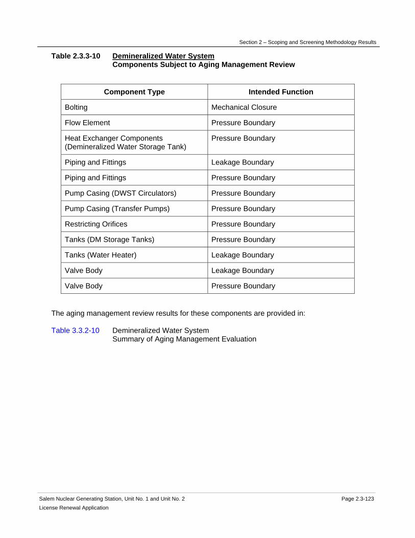
Section 2 – Scoping and Screening Methodology Results
Salem Nuclear Generating Station, Unit No. 1 and Unit No. 2 Page 2.3-123 License Renewal Application
Table 2.3.3-10 Demineralized Water System Components Subject to Aging Management Review
Component Type Intended Function
Bolting Mechanical Closure
Flow Element Pressure Boundary
Heat Exchanger Components (Demineralized Water Storage Tank)
Pressure Boundary
Piping and Fittings Leakage Boundary
Piping and Fittings Pressure Boundary
Pump Casing (DWST Circulators) Pressure Boundary
Pump Casing (Transfer Pumps) Pressure Boundary
Restricting Orifices Pressure Boundary
Tanks (DM Storage Tanks) Pressure Boundary
Tanks (Water Heater) Leakage Boundary
Valve Body Leakage Boundary
Valve Body Pressure Boundary
The aging management review results for these components are provided in: Table 3.3.2-10 Demineralized Water System Summary of Aging Management Evaluation

Section 2 – Scoping and Screening Methodology Results
Salem Nuclear Generating Station, Unit No. 1 and Unit No. 2 Page 2.3-124 License Renewal Application
2.3.3.11 Emergency Diesel Generator & Auxiliaries System
System Purpose The Emergency Diesel Generator and Auxiliaries System is a standby mechanical system designed to supply electrical power to key plant components when normal offsite power sources are not available. The Emergency Diesel Generator and Auxiliaries System is in scope for license renewal. The purpose of the Emergency Diesel Generator and Auxiliaries System is to provide electrical power for engineered safety features when normal offsite power is not available. Any two of the three diesel generators and their associated vital busses can supply sufficient power for operation of the required safeguards equipment for a design basis LOCA coincident with a loss of offsite power. The Emergency Diesel Generator and Auxiliaries System accomplishes this purpose by utilizing diesel engines to rotate electric generators attached to the diesel engines. The diesel engines use oil provided by the Fuel Oil System. The Jacket Cooling Water System, Lubricating Oil System, Starting Air System and Turbo Boost Air piping and components support emergency diesel engine operation. However, portions of the Starting Air System and Turbo Boost Air System do not perform an intended function and are not in scope. Each diesel engine will be automatically started by Safeguards Equipment Control upon the occurrence of a safety injection signal, indication of a loss of offsite power to the associated 4160 volt vital bus, or loss of voltage to two out of three 4160 volt vital busses. System Operation The Emergency Diesel Generator and Auxiliaries System is comprised of three (3) Emergency Diesel Generators per unit, lubrication, cooling water, starting and turbo boost air supply systems, pumps, compressors, heat exchangers, instrumentation and control, and piping and other components. The Emergency Diesel Generator and Auxiliaries System supplies power to 4160V vital busses. The Emergency Diesel Generator and Auxiliaries System is normally in standby. The diesel engines will be automatically started by the Safeguards Equipment Controller upon the occurrence of a safety injection signal, indication of a loss of offsite power to the associated 4160 volt vital bus, or loss of voltage to two out of three 4160 volt vital busses. The diesel engines can also be started manually from the control room or the local panel. The generators are evaluated with the 4160-volt System. The operating temperature of each diesel engine is controlled by the jacket water cooling subsystem, a closed loop cooling system that removes heat from the diesel engine. The engine-driven jacket water pump circulates cooling water through the engine manifold and turbocharger via a three-way thermostatically controlled valve. The three-way valve directs the water through the diesel generator jacket water heat exchanger where the water is cooled by the Service Water System. If the water temperature is too low, the valve automatically bypasses the diesel generator jacket water heat exchanger. Immersion heaters are installed in the engine to maintain water temperature at standby conditions. Makeup to the jacket water expansion tank comes from the Demineralized Water System.

Section 2 – Scoping and Screening Methodology Results
Salem Nuclear Generating Station, Unit No. 1 and Unit No. 2 Page 2.3-125 License Renewal Application
The Emergency Diesels are lubricated by a closed-cycle lube oil subsystem. Lube oil is pumped from the engine and engine turbochargers through a filter, the lube oil cooler, a strainer, and back to the engine. A pre-lube pump and stand-by lube oil heater are also included in the loop. Cooling water for the lube oil cooler is provided by the Service Water System. The emergency diesel starting air subsystem consists of air compressors, air receivers, pulsation dampeners, moisture separators, filters, valves and piping. The emergency diesel starting air subsystem supplies compressed air to two pairs of diesel engine air start motors. The emergency diesel starting air subsystem consists of two compressors, two pulsation dampeners, an after cooler, a moisture separator and an after filter feeding two receivers. Each receiver supplies a pair of air start motors on the diesel engine. Either pair of air start motors is capable of starting the diesel engine within the rated time, and each receiver is capable of three cold diesel starts. The two receivers, two compressors and two pairs of air start motors provide redundancy for the starting air subsystem. The emergency diesel turbo boost air subsystem consists of an inlet filter, an air compressor, a pulsation dampener, two air receivers, valves and piping. The emergency diesel turbo boost air subsystem supplies compressed air to the turbocharger to assist the rapid starting of the diesel engine and to accommodate large load increases such as a Service Water or Component Cooling Water pump during emergency safeguards loading. Two receivers provide redundancy for the turbo boost air subsystem. For more detailed information, see UFSAR Sections 8.3.1.5 and 9.5.5 through 9.5.7. System Boundary The Emergency Diesel Generator and Auxiliaries System boundary encompasses the diesel engines and turbochargers, the combustion air flow path through the turbocharger and diesel engine to the exhaust, the lubrication oil flow path, the jacket cooling water flow path, the starting air flow path and the turbo boost air flow path. The Fuel Oil System delivers the fuel oil through the fuel oil booster pump and secondary filter directly to the associated diesel engine. The fuel oil booster pump and secondary filter and all upstream components are scoped with the Fuel Oil System. The combustion air flow path begins at the air intake filter, and continues through the intake silencer, turbo charger, diesel engine, and exhaust silencer to the exhaust above the Auxiliary Building roof. The jacket cooling water flow path begins at the diesel engine and turbocharger and continues through the diesel generator jacket water heat exchanger and the aftercooler to the jacket water pump and ends at the inlets to the diesel engine and turbocharger. Also included are the aftercooler heater, expansion tank, and connecting piping. The lubrication oil flow path begins at the diesel engine and continues through the engine-driven lube oil pump to the filter to the diesel generator lube oil cooler and ends at and includes the strainer to the diesel engine. Also included in the boundary are the flow path from the engine to the pre-lube pump and lube oil heater, and the flow path from the crankcase exhausters to the crankcase vent.

Section 2 – Scoping and Screening Methodology Results
Salem Nuclear Generating Station, Unit No. 1 and Unit No. 2 Page 2.3-126 License Renewal Application
The starting air flow path begins at the filter inlet to the diesel starting air compressor and continues through the diesel starting air compressor to the pulsation dampener, to the after cooler, moisture separator, afterfilter, diesel starting air receiver and ends at the inlet to the diesel engine starting air motors. The drain connections from the moisture separator and diesel starting air receivers to the drain collection bottle were installed as a housekeeping measure to keep the floor dry, are not required for system operation, and are not in the license renewal boundary. The turbo boost air flow path begins at the filter inlet to the diesel turbo boost air compressor and continues through the diesel turbo boost air compressor, to the pulsation dampener, to the diesel turbo boost air receiver and ends at the inlet to the turbocharger. The drain connections from the diesel turbo boost air receivers to the drain collection bottle were installed as a housekeeping measure to keep the floor dry, are not required for system operation, and are not in the license renewal boundary. Not evaluated in the scoping boundary are the diesel generator lube oil cooler heat exchanger and diesel generator jacket cooling water heat exchanger, which are evaluated with the Service Water System. Also not evaluated in the scoping boundary are the generators and connected electrical components, which are evaluated with the 4160 Volt System. Also not included in the scoping boundary for license renewal are the diesel turbo boost air compressor and pulsation dampener, and the diesel starting air compressors, pulsation dampeners, and after cooler. This portion of the system is not safety related and is not required to function during the accident. In addition, since this portion of the system contains gas it does not support the system's leakage boundary function. Therefore this portion of the system does not perform an intended function and is not included in the scope of license renewal. All other associated piping, components and instrumentation contained within the flow paths described above are included in the system evaluation boundary. Not included in the Emergency Diesel Generator and Auxiliaries System license renewal scoping boundary are the following interfacing systems, which are separately evaluated as license renewal systems: 4160 Volt System Demineralized Water System Fuel Oil System Service Water System Reason for Scope Determination The Emergency Diesel Generator and Auxiliaries System meets 10 CFR 54.4(a)(1) because it is a safety-related system that is relied upon to remain functional during and following design basis events. The Emergency Diesel Generator and Auxiliaries System is not in scope under 10 CFR 54.4(a)(2) because failure of nonsafety-related portions of the system would not prevent satisfactory accomplishment of function(s) identified for 10 CFR 54.4(a)(1). The Emergency Diesel Generator and Auxiliaries System also meets 10 CFR 54.4(a)(3) because it is relied upon to perform a function that demonstrates compliance with the Commission's regulation for Fire Protection (10 CFR 50.48) and Station Blackout (10 CFR 50.63). The Emergency Diesel Generator and Auxiliaries System is not relied upon in any safety analyses or plant evaluations to perform a function that demonstrates compliance with the Commission's regulation for Environmental Qualification (10 CFR 50.49), Pressurized Thermal Shock (10 CFR 50.61), or Anticipated Transient Without Scram (10 CFR 50.62).

Section 2 – Scoping and Screening Methodology Results
Salem Nuclear Generating Station, Unit No. 1 and Unit No. 2 Page 2.3-127 License Renewal Application
System Intended Functions 1. Provide power to safety-related components. The Emergency Diesel Generator and Auxiliaries System is required to power safety-related equipment in the event normal power supplies are not available. 10 CFR 54.4(a)(1) 2. Relied upon in safety analyses or plant evaluations to perform a function that demonstrates compliance with the Commission's regulations for Fire Protection (10 CFR 50.48). The Emergency Diesel Generator and Auxiliaries System is required to supply electrical power to systems required for safe shutdown. 10 CFR 54.4(a)(3) 3. Relied upon in safety analyses or plant evaluations to perform a function that demonstrates compliance with the Commission's regulations for Station Blackout (10 CFR 50.63). The Emergency Diesel Generator and Auxiliaries System is required to provide onsite power during the restoration process. 10 CFR 54.4(a)(3) UFSAR References 8.3.1.5 9.5.5 9.5.6 9.5.7 License Renewal Boundary Drawings Unit 1: LR-205241 Sheet 1 LR-205241 Sheet 2 LR-205241 Sheet 3 LR-205249 Sheet 2 LR-205249 Sheet 3 Unit 2: LR-205241 Sheet 4 LR-205241 Sheet 5 LR-205241 Sheet 6 Unit Common: None
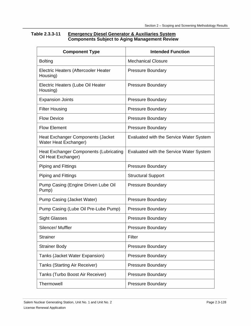
Section 2 – Scoping and Screening Methodology Results
Salem Nuclear Generating Station, Unit No. 1 and Unit No. 2 Page 2.3-128 License Renewal Application
Table 2.3.3-11 Emergency Diesel Generator & Auxiliaries System Components Subject to Aging Management Review
Component Type Intended Function
Bolting Mechanical Closure
Electric Heaters (Aftercooler Heater Housing)
Pressure Boundary
Electric Heaters (Lube Oil Heater Housing)
Pressure Boundary
Expansion Joints Pressure Boundary
Filter Housing Pressure Boundary
Flow Device Pressure Boundary
Flow Element Pressure Boundary
Heat Exchanger Components (Jacket Water Heat Exchanger)
Evaluated with the Service Water System
Heat Exchanger Components (Lubricating Oil Heat Exchanger)
Evaluated with the Service Water System
Piping and Fittings Pressure Boundary
Piping and Fittings Structural Support
Pump Casing (Engine Driven Lube Oil Pump)
Pressure Boundary
Pump Casing (Jacket Water) Pressure Boundary
Pump Casing (Lube Oil Pre-Lube Pump) Pressure Boundary
Sight Glasses Pressure Boundary
Silencer/ Muffler Pressure Boundary
Strainer Filter
Strainer Body Pressure Boundary
Tanks (Jacket Water Expansion) Pressure Boundary
Tanks (Starting Air Receiver) Pressure Boundary
Tanks (Turbo Boost Air Receiver) Pressure Boundary
Thermowell Pressure Boundary
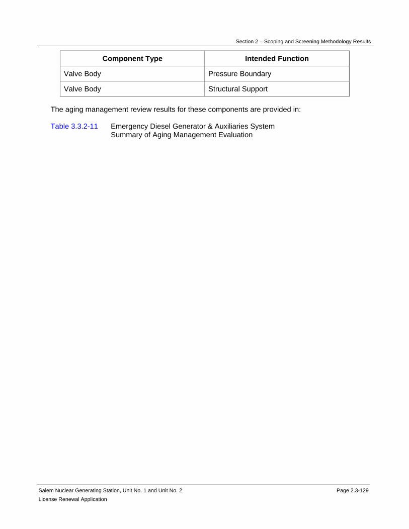
Section 2 – Scoping and Screening Methodology Results
Salem Nuclear Generating Station, Unit No. 1 and Unit No. 2 Page 2.3-129 License Renewal Application
Component Type Intended Function
Valve Body Pressure Boundary
Valve Body Structural Support The aging management review results for these components are provided in: Table 3.3.2-11 Emergency Diesel Generator & Auxiliaries System Summary of Aging Management Evaluation

Section 2 – Scoping and Screening Methodology Results
Salem Nuclear Generating Station, Unit No. 1 and Unit No. 2 Page 2.3-130 License Renewal Application
2.3.3.12 Fire Protection System
System Purpose The Fire Protection System is a normally operating mechanical system, designed for the rapid detection and suppression of a fire at the plant. The Fire Protection System is in scope for license renewal. However, portions of the Fire Protection System are not required to perform intended functions and are not in scope. The Fire Protection System consists of the following plant systems: fire protection water systems, carbon dioxide systems, Halon system, foam system, portable fire extinguishers, and fire detection and alarm systems. The Fire Protection System is in scope for license renewal. However, portions of the fire protection water system and fire detection and alarm systems are not required to perform intended functions and are not in scope. The Fire Protection System works in conjunction with physical plant design features to provide for overall protection for Salem Generating Station (SGS). The physical plant features consist of fire barriers, fire doors and fire rated enclosures. The fire protection water system in the Containment Structure has a portion of piping and valves that are safety-related. The fire protection water system inside containment provides fire water to protect the reactor coolant pump lubrication system and the iodine removal units. The purpose of the Fire Protection System is to prevent fires from starting, promptly detect and suppress fires to limit damage, and in the event of a fire allow for safe shutdown to occur. The Fire Protection System accomplishes this purpose by providing fire protection equipment in the form of detectors, alarms, fire barriers and suppression systems for selected areas of the plant. In addition, the Fire Protection System provides a backup source of water to the Auxiliary Feedwater System in the event of loss of the Auxiliary Feedwater Storage Tanks. The Fire Protection System includes subsystems that can be actuated automatically or manually upon detection of a fire. The SGS fire protection water system is physically connected to the Hope Creek Generating Station (HCGS) water fire protection system by the use of sectionalizing valves. The two systems are normally isolated from each other. System Operation The fire protection suppression system is comprised of water, carbon dioxide, Halon and foam suppression subsystems described below. Included in this system are the fire barrier penetrations and fire wrap for the panels and cable trays. The fire protection water system is supplied by two diesel-driven fire pumps. Both pumps are housed in a building outside of the power block. These pumps are automatically started on low header pressure or on loss of ac power, and can be manually started locally at the control cabinet or from the engine in the event of a controller failure. Each diesel-driven fire pump has its own fuel supply located inside the pump house. Both pumps take suction from the fresh water and fire protection water storage tanks. Each fire pump has a discharge line that connects to the main fire header loop. The pumps, tanks, discharge piping from the pumps, and controls are completely separate and redundant. The diesel engines and associated Diesel Fuel Oil Systems are in scope but evaluated in the Fuel Oil System license renewal boundary.

Section 2 – Scoping and Screening Methodology Results
Salem Nuclear Generating Station, Unit No. 1 and Unit No. 2 Page 2.3-131 License Renewal Application
The fire protection jockey pump normally maintains fire water system pressure in the main fire header loop, with the diesel fire protection pumps maintained in standby. The discharge lines from the diesel fire protection pumps connect with the underground main fire header loop. The fire header loop encircles the plant and provides fire protection water to the yard fire hydrants, fixed pipe water suppression systems and fire hose stations. The fire water enters the power block at several locations from branch headers off the main fire header loop. The main fire header loop also supplies remote facilities away from the power block. Some of these locations are not in scope. Post indicator sectionalizing valves are provided on the loop to allow isolation of the various sections for maintenance. The fresh water storage tank heating water circulator recirculates water from the fresh water and fire protection water storage tank through the fresh water storage tank heat exchanger to maintain the water temperature above freezing. The fire water suppression system includes both dry and wet pipe sprinklers and water spray (deluge) systems. Hose stations have been provided within the plant buildings. The carbon dioxide flooding subsystem protects the emergency diesel generator and the emergency diesel oil day tank storage rooms and associated control rooms; diesel oil storage tank rooms and the diesel oil transfer pump rooms. A carbon dioxide system also protects the turbine generator exciter (Unit 1) and alternator (Unit 2). Local temperature sensors actuate most carbon dioxide systems automatically. Both of these carbon dioxide Fire Protection Systems are in scope for license renewal. An additional carbon dioxide flooding system is located outdoors, north of the Unit 2 turbine building, which provides protection of the standby gas turbine. However, this carbon dioxide system does not perform an intended function and therefore, is not in scope and not subject to aging management review. The total flooding Halon subsystem provides fire protection for each of the relay rooms. Halon storage bottles are permanently connected to the system discharge piping. In the event of a fire, the Halon system can be actuated either automatically or can be manually initiated. A Halon system also provides protection to the Dimension 2000 Telephone building but this building is not in scope and therefore this Halon system is not in scope and not subject to aging management review. The manually actuated foam subsystem provides fire protection for the main fuel oil storage tank located in the yard. When actuated, the foam concentrate is mixed with water from the main fire header and discharges at the top of the fuel oil storage tank through the discharge header. A manually-actuated foam system is also provided to the gas turbine. However, the foam system for the gas turbine is not in scope and therefore this foam system is not subject to aging management review. Portable fire extinguishers are provided throughout the station based on NFPA 10 guidance for the type of hazards present. There are several classes of extinguishers (A, B, C, and D) used at the station. These extinguishers are periodically inspected in accordance to NFPA regulations by the use of station procedures and are replaced on a conditional, as-needed basis. They provide backup fire fighting capability only and are considered as a consumable, and therefore not subject to aging management review. Each reactor coolant pump motor in the Containment Structure is equipped with an oil collection system consisting of a series of pans and drainage piping leading to oil drain tanks. Each reactor coolant bearing lube oil lift pump is protected by the fixed water fire suppression system.
Section 2 – Scoping and Screening Methodology Results
Salem Nuclear Generating Station, Unit No. 1 and Unit No. 2 Page 2.3-132 License Renewal Application
Early warning fire and smoke detection and alarm systems provide a means of detecting the presence of a fire and initiating an alarm in the Main Control Rooms. In addition, some of these fire detection systems will automatically initiate the appropriate fire protection system. There are three types of detectors used at the station: ionization, photoelectric and thermal detectors. Ionization detectors or incipient fire detectors (IFD) sound an alarm at the presence of invisible combustion products during the incipient stage of fire. Photoelectric smoke detectors, which will respond to visible smoke, are used in areas where fire potential might exist and areas that are exposed to a radiation dose rate greater than that recommended for ionization detectors. The rate compensating thermal detectors respond to area high temperature conditions. All of the detector signals go to the fire protection status panels located in the main control rooms. For more detailed information, see UFSAR Section 9.5.1. System Boundary The boundary of the fire protection water system begins with the two fresh water and fire protection water storage tanks and continues through the two diesel-driven fire pumps to the main fire header loop, and terminates at the suppression systems, hydrants and hose stations. Also within the boundary are the fresh water storage tank heating water circulators and fresh water storage tank heat exchangers. Included in this boundary is a cross connect from the HCGS fire protection main fire header loop that is physically connected but isolated from the SGS fire protection yard loop. The main fire header loop continues around the perimeter of the power block, and includes numerous branch lines that supply various spray systems, hose stations and fire hydrants. Sectionalizing post indicator type valves are provided on the main fire header loop to allow isolation of various sections for maintenance. Also included is the line providing an alternate suction source for the Auxiliary Feedwater System beginning at the check valve entering the Auxiliary Building from the Service Building. There are two separate carbon dioxide systems at each of the SGS units. The first system is for the total flooding carbon dioxide suppression system protecting three fire zones, Emergency Diesel Generator and diesel oil day tank storage rooms along with the associated control rooms; diesel oil storage tank rooms and the diesel oil transfer pump rooms. This system begins at the carbon dioxide storage tank, and continues through a normally closed automatic discharge valve into the three fire zones, through the header, and ends at the spray nozzles for each of the three fire zones. Upon actuation in a zone, the carbon dioxide discharges through the header and into the spray nozzles while the remaining automatic discharge valves remain closed. Each of the three fire zones has a normally closed feed distribution header valve which feeds into each room's spray nozzles. The second carbon dioxide system is for the local application of carbon dioxide for the oil piping located inside the main turbine generator exciter housing. The boundary starts at the carbon dioxide storage tank and continues through the system to a normally closed automatic discharge valve, through the header and ends at the spray nozzles discharging into the main generator housing. The boundary for the total flooding Halon suppression system that protects the relay rooms begins at the Halon tanks and continues through the flexible hose connections to the Halon discharge piping and valves continuing and ends at the discharge nozzles. In case of fire, the Halon storage cylinders can automatically or manually discharge into the relay rooms to suppress fires.

Section 2 – Scoping and Screening Methodology Results
Salem Nuclear Generating Station, Unit No. 1 and Unit No. 2 Page 2.3-133 License Renewal Application
The boundary of the foam fire protection system begins with the connector that joins the foam concentrate storage tank to the fire water header, and continues through the tank to the foam solution header and ends at the foam discharge header feeding the Fuel Oil Storage Tank. Portable fire extinguishers are included within the system evaluation boundary, however a flow path description is not applicable for this self-contained portable equipment which is treated as a consumable. All associated piping, components and instrumentation contained within the flow paths described above is included in the system evaluation boundary. Also included in the system evaluation boundary are the physical plant design features that consist of fire barrier walls and slabs, fire barriers, fire doors and fire rated enclosures located in the Containment Structure, Service Building, Turbine Building, Fuel Handling Building and Service Water Pump House. Not included in the Fire Protection System license renewal scoping boundary are the following interfacing systems, which are separately evaluated as license renewal systems: Auxiliary Feedwater System Compressed Air System Fuel Oil System Reason for Scope Determination The Fire Protection System meets 10 CFR 54.4(a)(1) because it is a safety-related system that is relied upon to remain functional during and following design basis events. The Fire Protection System is in scope under 10 CFR 54.4(a)(2) because failure of nonsafety-related portions of the system could prevent satisfactory accomplishment of function(s) identified for 10 CFR 54.4(a)(1). It meets 10 CFR 54.4(a)(3) because it is relied upon in the safety analyses or plant evaluations to perform functions that demonstrates compliance with the Commission's regulations for Fire Protection (10 CFR 50.48). The Fire Protection System is not relied upon in any safety analyses or plant evaluations to perform a function that demonstrates compliance with the Commission's regulations for Environmental Qualification (10 CFR 50.49), Anticipated Transients Without Scram (10 CFR 50.62), Pressurized Thermal Shock (10 CFR 50.61) or Station Blackout (10 CFR 50.63). System Intended Functions 1. Provide primary containment boundary. Isolation valves provide containment isolation capability. 10 CFR 54.4(a)(1) 2. Resist nonsafety-related SSC failure that could prevent satisfactory accomplishment of a safety-related function. Nonsafety-related piping and components containing water and located in proximity to equipment that performs safety-related functions is required to maintain leakage boundary integrity to preclude spatial interaction with the safety-related equipment. The Fire Protection Water Storage Tank(s) also provides a backup source of water to the Auxiliary Feedwater System in the event of a loss of the Auxiliary Water Feed Storage Tank. 10 CFR 54.4(a)(2) 3. Relied upon in safety analysis or plant evaluations to perform a function that demonstrates compliance with the Commission's regulations for Fire Protection (10 CFR 50.48). The Fire

Section 2 – Scoping and Screening Methodology Results
Salem Nuclear Generating Station, Unit No. 1 and Unit No. 2 Page 2.3-134 License Renewal Application
Protection System works in conjunction with fire barriers and other plant design features, including established safe shutdown systems and procedures to demonstrate compliance with fire protection regulations. 10 CFR 54.4(a)(3). UFSAR References 3.5.2.3.1 3.6.5.12 9.5.1 License Renewal Boundary Drawings Unit 1: LR-600257 Sheet 1 Unit 2: LR-600256 Sheet 1 Unit Common: LR-205221 Sheet 1 LR-205222 Sheet 1 LR-205222 Sheet 2 LR-205222 Sheet 3 LR-205222 Sheet 4

Section 2 – Scoping and Screening Methodology Results
Salem Nuclear Generating Station, Unit No. 1 and Unit No. 2 Page 2.3-135 License Renewal Application
Table 2.3.3-12 Fire Protection System Components Subject to Aging Management Review
Component Type Intended Function
Bolting Mechanical Closure
Concrete Curbs Direct Flow
Damper Housing Fire Barrier
Damper Housing Pressure Boundary
Doors Fire Barrier
Fire Barriers (Masonry Walls: Exterior) Fire Barrier
Fire Barriers (Masonry Walls: Interior) Fire Barrier
Fire Barriers (Penetration Seals) Fire Barrier
Fire Barriers (Walls, Ceilings, and Floors) Fire Barrier
Fire Barriers (Wraps) Fire Barrier
Fire Hydrant Pressure Boundary
Flow Alarm Switch Pressure Boundary
Flow Element (F-3423) Pressure Boundary
Gas Bottles (Halon) Pressure Boundary
Heat Exchanger Components (Fresh Water Storage Tank)
Pressure Boundary
Hose Manifold Pressure Boundary
Odorizer Pressure Boundary
Piping and Fittings Pressure Boundary
Pump Casing (Diesel Driven Fire Pump ) Pressure Boundary
Pump Casing (Fresh Water Storage Tank Heating Water Circulators)
Pressure Boundary
Pump Casing (Jockey Fire Pump) Pressure Boundary
Restricting Orifices Pressure Boundary
Sight Glasses (Foam Storage Tanks) Pressure Boundary
Spray Nozzles (CO2, Halon) Spray

Section 2 – Scoping and Screening Methodology Results
Salem Nuclear Generating Station, Unit No. 1 and Unit No. 2 Page 2.3-136 License Renewal Application
Component Type Intended Function
Spray Nozzles (Foam) Spray
Spray Nozzles (Iodine Removal Filter ) Spray
Sprinkler Heads Pressure Boundary
Sprinkler Heads Spray
Strainer Filter
Strainer Body Pressure Boundary
Tanks (10 Ton Carbon Dioxide) Pressure Boundary
Tanks (750 lb Carbon Dioxide) Pressure Boundary
Tanks (Fire Water Storage) Pressure Boundary
Tanks (Foam Concentrate Storage) Pressure Boundary
Tanks (Reactor Coolant Pump Oil Collection Enclosure)
Leakage Boundary
Tanks (Retarding Chamber) Pressure Boundary
Thermowell Pressure Boundary
Valve Body Pressure Boundary The aging management review results for these components are provided in: Table 3.3.2-12 Fire Protection System Summary of Aging Management Evaluation

Section 2 – Scoping and Screening Methodology Results
Salem Nuclear Generating Station, Unit No. 1 and Unit No. 2 Page 2.3-137 License Renewal Application
2.3.3.13 Fresh Water System
System Purpose The intended function of the Fresh Water System for license renewal is to maintain leakage boundary integrity to preclude system interactions. For this reason, this system's pressure retaining components located in proximity to other components performing safety-related functions have been included in the scope of license renewal. This system is not required to operate to support license renewal intended functions, and is in scope for potential spatial interaction. The Fresh Water System is a normally operating mechanical system designed to provide the plants with a source of water for potable, sanitary, fire protection or process make-up use. The Fresh Water System is in scope for license renewal. The Fresh Water System has interfaces with several other systems and components that are not within the license renewal boundary of the Fresh Water System, and are evaluated separately. These include the Chilled Water System, Demineralized Water System, Fire Protection System, Heating Water & Heating Steam System, Main Condensate and Feedwater, Main Condenser and Air Removal System, Main Steam System, Main Turbine and Auxiliaries System, Non-radioactive Drain System, Non-radioactive Liquid Waste System, and the Steam Generators. The purpose of the Fresh Water System is to provide the plants with a source of raw water for non-potable use, or for further treatment for potable or plant use. The Fresh Water System accomplishes this purpose via production wells, pumps, heat exchangers, tanks, piping, piping components, and plumbing fixtures. System Operation The Fresh Water System is comprised of the following major components: production wells, pumps, heat exchangers, tanks, piping, piping components, and plumbing fixtures. The fresh water and fire protection water storage tanks, heating water circulators, and heat exchangers are evaluated with the Fire Protection System. Only the liquid level above 300,000 gallons in the fire protection water storage tanks is used for the Fresh Water System. The suction pipe for this system is above the corresponding height to ensure that the water level in the fire protection water storage tanks is maintained above the minimum liquid level. Under normal operations, the production wells supply raw water to the fresh water and fire protection water storage tanks. The Fresh Water System pumps take suction from the fresh water and fire protection water storage tanks and distribute raw water to locations onsite, including plant buildings such as the Auxiliary, Service, and Turbine Buildings. A dedicated circulator and heat exchanger circulate the contents of the two fresh water and fire protection water storage tanks to prevent freezing. A separate fresh water tank with booster pumps forward raw water to a fresh water chlorination tank before supplying the water to the site for potable usage. The Fresh Water System supplies the following systems with raw water: Chilled Water System, Condensate and Feedwater Auxiliaries Feed System, Demineralized Water System, Fire Protection System, Heating Water & Heating Steam System, Main Condensate and Feedwater, Main Condenser and Air Removal System, Main Steam System, Main Turbine and Auxiliaries System, Non-radioactive Drain System, Non-radioactive Liquid Waste System, and the Steam Generators.

Section 2 – Scoping and Screening Methodology Results
Salem Nuclear Generating Station, Unit No. 1 and Unit No. 2 Page 2.3-138 License Renewal Application
For more detailed information, see UFSAR Sections 9.2.4 and 9.5.1.7. System Boundary The license renewal scoping boundary of the Fresh Water System encompasses the liquid filled portion of the system that is located in proximity to equipment performing a safety-related function. This includes the liquid filled portions of the Fresh Water System located within the Auxiliary Buildings. Included in this boundary are pressure retaining components relied upon to preserve the leakage boundary intended function of this system. For more information, refer to the license renewal boundary drawings for identification of this boundary, shown in red. Components that are not required to support the system's leakage boundary intended function are not included in the scope of license renewal. Not included in the Fresh Water System license renewal scoping boundaries are the following interfacing systems, which are separately evaluated as license renewal systems: Chilled Water System Demineralized Water System Fire Protection System Heating Water & Heating Steam System Main Condensate and Feedwater System Main Condenser and Air Removal System Main Steam System Main Turbine and Auxiliaries System Non-radioactive Drain System Non-radioactive Liquid Waste System Steam Generators Reason for Scope Determination The Fresh Water System is not in scope under 10 CFR 54.4(a)(1) because no portions of the system are safety-related or relied upon to remain functional during and following design basis events. The Fresh Water System is in scope under 10 CFR 54.4(a)(2) because failure of nonsafety-related portions of the system would prevent satisfactory accomplishment of function(s) identified for 10 CFR 54.4(a)(1). The system is not in scope under 10 CFR 54.4(a)(3) because it is not relied upon in safety analyses or plant evaluations to perform a function that demonstrates compliance with the Commission's regulations for Fire Protection (10 CFR 50.48), Environmental Qualification (10 CFR 50.49), Pressurized Thermal Shock (10 CFR 50.61), Anticipated Transient Without Scram (10 CFR 50.62), or Station Blackout (10 CFR 50.63). System Intended Functions 1. Resist nonsafety-related SSC failure that could prevent satisfactory accomplishment of a safety-related function. The Fresh Water System has the potential for spatial interaction with safety-related components in the Auxiliary Buildings. 10 CFR 54.4(a)(2) UFSAR References 9.2.4 9.5.1.7

Section 2 – Scoping and Screening Methodology Results
Salem Nuclear Generating Station, Unit No. 1 and Unit No. 2 Page 2.3-139 License Renewal Application
License Renewal Boundary Drawings Unit 1: None Unit 2: None Unit Common: LR-205216 Sheet 1 LR-205216 Sheet 2 LR-205324 Sheet 1

Section 2 – Scoping and Screening Methodology Results
Salem Nuclear Generating Station, Unit No. 1 and Unit No. 2 Page 2.3-140License Renewal Application
Table 2.3.3-13 Fresh Water System Components Subject to Aging Management Review
Component Type Intended Function
Bolting Mechanical Closure
Piping and Fittings Leakage Boundary
Valve Body Leakage Boundary The aging management review results for these components are provided in: Table 3.3.2-13 Fresh Water System Summary of Aging Management Evaluation

Section 2 – Scoping and Screening Methodology Results
Salem Nuclear Generating Station, Unit No. 1 and Unit No. 2 Page 2.3-141 License Renewal Application
2.3.3.14 Fuel Handling & Fuel Storage System
System Purpose The Fuel Handling and Fuel Storage System is a mechanical system designed to manipulate and store new and spent fuel and to control fuel geometry when not in the core. The Fuel Handling and Fuel Storage System consists of the following plant systems: Fuel Handling System, and Fuel Handling Tools. The purpose of the Fuel Handling and Fuel Storage System is to provide a safe, effective means of storing, transporting and handling fuel from the time it reaches the plant in an unirradiated condition until it leaves the plant after post-irradiation cooling. The Fuel Handling and Fuel Storage System controls fuel storage positions to assure a geometrically safe configuration with respect to criticality, ensure adequate shielding of irradiated fuel for plant personnel to accomplish normal operations, prevent mechanical damage to the stored fuel that could result in significant release of radioactivity from the fuel, and provide means for the safe handling of new and irradiated fuel. The Fuel Handling and Fuel Storage System accomplishes its purpose by using the Fuel Handling Crane, Spent Fuel Pool Bridge, Manipulator Crane, Fuel Transfer System, and other fuel transfer handling tools and equipment to move fuel, and by using storage racks to safely and securely hold new fuel in the new fuel storage pit and irradiated fuel in the spent fuel pool. The Fuel Handling and Fuel Storage System is used during fuel movement to, from, or within the reactor vessel or the spent fuel pools, and through the Fuel Transfer Tube and fuel transfer pool, to store and move new and spent fuel. The storage racks are in scope since they perform a safety-related function to maintain fuel storage geometry to prevent criticality. The structural support members and components of the Manipulator Crane, Fuel Handling Crane, Spent Fuel Pool Bridge, and New Fuel Elevator are in scope for license renewal because they have the potential to allow spatial interaction with safety-related equipment in the Containment Building or Fuel Handling Building and are required to maintain structural integrity during a design basis seismic event. The Fuel Transfer Tube and its flanges, isolation valve, closure plate and test lines are in scope for license renewal as they provide a pressure boundary. The Fuel Transfer System Conveyor Car and upending devices are Class III active components whose failure would not affect safety related functions or components and are therefore not in scope for license renewal. The upending device rack/frame is a passive component which handles irradiated fuel and is also not in scope for license renewal. Special purpose tools are used to support refueling activities, to facilitate transfer of nuclear fuel and to service the reactor vessel internals. They do not perform a license renewal intended function and are not in scope for license renewal.

Section 2 – Scoping and Screening Methodology Results
Salem Nuclear Generating Station, Unit No. 1 and Unit No. 2 Page 2.3-142 License Renewal Application
The Reactor Cavity, the Refueling Canal, Containment and Fuel Handling Building penetration sleeves and bellows associated with the Fuel Transfer Tube, Transfer Pool, Spent Fuel Storage Pool, New Fuel Storage Pit, and Decontamination Pit are evaluated as part of the associated building structure. The Spent Fuel Cooling System maintains Spent Fuel Pool water temperature within acceptable limits. That system is evaluated for aging management with the Spent Fuel Cooling System. System Operation The Fuel Handling and Fuel Storage System is comprised of the equipment and structures utilized for handling new and spent fuel in a safe manner during refueling and fuel transfer operations. The Fuel Handling equipment is comprised of the Fuel Handling Crane, Spent Fuel Pool Bridge, the Manipulator Crane, Cask Handling Crane, associated tools, the New Fuel Elevator, the Fuel Transfer Carriage, the upending devices, the Fuel Transfer Tube assembly, New and Spent Fuel Racks, and the special purpose tools. Fuel Handling structures within the Containment Building are comprised of the Reactor Cavity, the Refueling Canal, and the Containment Penetration Sleeve and bellows assembly associated with the Fuel Transfer Tube. Fuel Handling structures within the Fuel Handling Building are comprised of the Transfer Pool, Spent Fuel Storage Pool, New Fuel Storage Pit, Fuel Handling Building Penetration Sleeve and bellows assembly associated with the Fuel Transfer Tube, and Decontamination Pit. Refueling operations are carried out using a Manipulator Crane which spans the Refueling Canal in the Containment Structure. The Manipulator Crane is a rectilinear bridge and trolley crane with a vertical mast extending down into the refueling water which is used to transfer fuel within the reactor core and to transfer new and spent fuel between the core and Fuel Transfer System. Fuel removed from the reactor core is transported to the Spent Fuel Pool from the Containment Structure through the Fuel Transfer Tube by means of the Fuel Transfer System. The Fuel Transfer System has an electrically-driven underwater conveyor car that runs on tracks extending from the refueling canal through the transfer tube and into the transfer pool. The transfer carriages are moved by cable drives, considered to be subcomponents of the transfer carriages. An upending device is provided at each end of the Fuel Transfer Tube to rotate fuel assemblies to a vertical position. The upending device rack/frame is rotated to a horizontal position for passage through the Fuel Transfer Tube and then rotated back to a vertical position in the Transfer Pool or Containment Structure for vertical removal or insertion of the fuel assembly. The Fuel Transfer Tube contains a gate valve on the Fuel Handling Building side and a flanged closure on the Containment Structure side. The flanged closure and only a portion of the Fuel Transfer Tube, which extends from the Containment liner plate to the flanged closure inside the Containment Reactor Cavity, provide the Containment pressure boundary. The Fuel Handling Crane is located in the Fuel Handling Building and is a Class I semi-gantry type crane used to transport new or spent fuel between their shipping container, storage racks and upending device. The Spent Fuel Storage Racks are located in the Spent Fuel Pool, which is separated by a wall with a weir gate from the Transfer Pool containing the upending device and the Fuel Transfer Tube gate valve. The Spent Fuel Pool Bridge also known as the

Section 2 – Scoping and Screening Methodology Results
Salem Nuclear Generating Station, Unit No. 1 and Unit No. 2 Page 2.3-143 License Renewal Application
motor-driven platform is a personnel observation platform which is a separate piece of equipment from the Fuel Handling Crane, although they can be coupled together to enable the two to travel as a single unit. The spent fuel storage racks are made from stainless steel and contain boral poison panels. The cells are welded together in a specified manner to become a freestanding structure, which is seismically qualified without depending on neighboring modules or Spent Fuel Pool walls for support. The Cask Handling Crane is used to transfer new fuel containers from the truck bay within the Fuel Handling Building to the laydown area near the new fuel storage area. It is also designed to move spent fuel shipping casks from the Transfer Pool to the decontamination pit and to the truck bay. The Cask Handling Crane is evaluated with the Cranes and Hoists system. The new fuel is received and stored dry in racks in the New Fuel Pit within the Fuel Handling Building and then transferred to the Transfer Pool when refueling is about to be initiated. The New Fuel Elevator is used to lower new fuel into the Transfer Pool and it is also specially designed to support and position fuel assemblies during fuel repairs. For more detailed information, see UFSAR Section 9.1 System Boundary The license renewal scoping boundary of the Fuel Handling and Fuel Storage System includes and encompasses the Manipulator Crane, Fuel Handling Crane, the Spent Fuel Bridge, the Fuel Transfer System including the carriage, the Fuel Transfer Tube, the New Fuel Elevator, Spent Fuel Racks and New Fuel Racks. Also included in the license renewal scoping boundary of the Fuel Handling and Fuel Storage System is the Fuel Transfer Tube and its flange at the Fuel Transfer Canal, the Fuel Transfer Tube test connections, and the Fuel Transfer Tube isolation valve at the Transfer Pool. The fuel transfer tube and its flanges, isolation valve, closure plate and test lines provide a pressure boundary. Not included in the Fuel Handling and Fuel Storage System scoping boundary are the Reactor Cavity, Refueling Canal, Spent Fuel Pool, Transfer Pool, New Fuel Storage Pit, Decontamination Pit, Containment and Fuel Handling Building Penetration Sleeves and bellows associated with the Fuel Transfer Tube, the Containment Polar Crane, and Monorail Hoists, Mobile Cherry Pickers, the Cask Handling Crane, and supports for components and tools. The Reactor Cavity, Refueling Canal, and the Containment Penetration Sleeve and bellows associated with the Fuel Transfer Tube are evaluated separately with the Containment Building. The Transfer Pool, Spent Fuel Pool, New Fuel Storage Pit, Fuel Handling Building Penetration Sleeve and bellows associated with the Fuel Transfer Tube, and the Decontamination Pit are evaluated with the Fuel Handling Building Structure. The Containment Polar Crane, Cask Handling Crane, Mobile Cherry Pickers, and associated cranes and Monorail Hoists not included with the Fuel Handling system above are evaluated separately with the Cranes and Hoists system. Supports for components are separately evaluated with the Structural Commodities group. Also not included are the special purpose tools and the conveyor car, upending devices and associated rack/frame. Not included in the Fuel Handling and Fuel Storage System license renewal scoping boundary are the following interfacing systems, which are separately evaluated as license renewal systems:

Section 2 – Scoping and Screening Methodology Results
Salem Nuclear Generating Station, Unit No. 1 and Unit No. 2 Page 2.3-144 License Renewal Application
Containment Structure Cranes and Hoists Fuel Handling Building Spent Fuel Pool Cooling Structural Commodities Reason for Scope Determination The Fuel Handling and Fuel Storage System meets 10 CFR 54.4(a)(1) because it is a safety-related system that is relied upon to remain functional during and following design basis events. It meets 10 CFR 54.4(a)(2) because failure of nonsafety-related portions of the system could prevent satisfactory accomplishment of function(s) identified for 10 CFR 54.4(a)(1). It does not meet 10 CFR 54(a)(3) because it is not relied upon in any safety analyses or plant evaluations to perform a function that demonstrates compliance with the Commission's regulations for Fire Protection (10 CFR 50.48), Environmental Qualification (10 CFR 50.49), Pressurized Thermal Shock (10 CFR 50.61), Anticipated Transient Without Scram (10 CFR 50.62), or Station Blackout (10 CFR 50.63). System Intended Functions 1. Provide primary containment boundary. The Fuel Transfer Tubes are sealed to prevent a containment release pathway. 10 CFR 54.4(a)(1) 2. Ensure adequate cooling in the spent fuel pool to maintain stored fuel within acceptable temperature limits. The fuel storage racks control fuel positions to assure the assemblies are always maintained in a subcritical condition, which facilitates spent fuel cooling. 10 CFR 54.4(a)(1) 3. Prevents criticality of fuel assemblies stored in the spent fuel pool. The Spent Fuel Racks are designed to provide for storage of fuel to support and maintain sufficient spacing and physical geometry with boral poison panels to prevent criticality of fuel assemblies stored in the spent fuel pool. 10 CFR 54.4(a)(1) 4. Resist nonsafety-related SSC failure that could prevent satisfactory accomplishment of a safety-related function. Fuel handling bridges and other equipment are seismically restrained to prevent damage to safety-related components and the nuclear fuel including the reactor. 10 CFR 54.4(a)(2) UFSAR References 9.1.1 9.1.2 9.1.4 License Renewal Boundary Drawings Unit 1: None Unit 2: None Unit Common: None
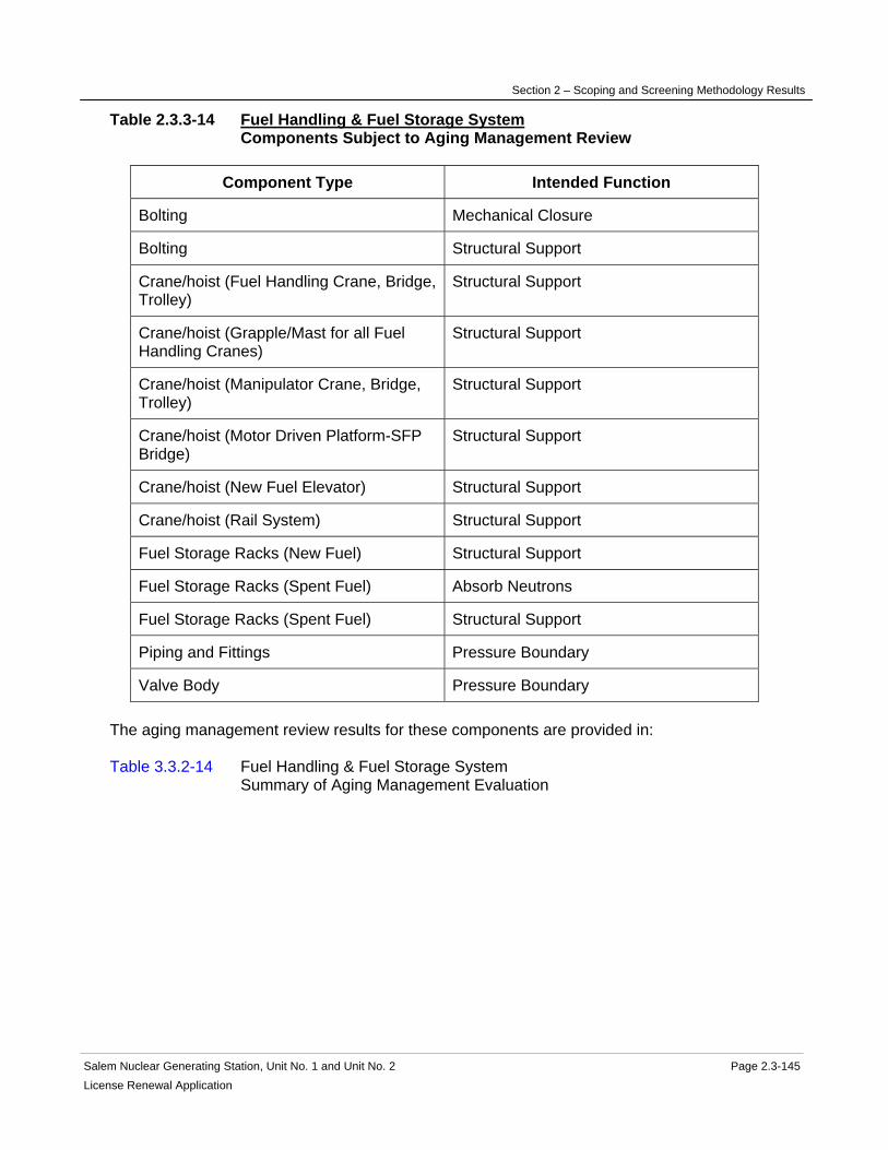
Section 2 – Scoping and Screening Methodology Results
Salem Nuclear Generating Station, Unit No. 1 and Unit No. 2 Page 2.3-145 License Renewal Application
Table 2.3.3-14 Fuel Handling & Fuel Storage System Components Subject to Aging Management Review
Component Type Intended Function
Bolting Mechanical Closure
Bolting Structural Support
Crane/hoist (Fuel Handling Crane, Bridge, Trolley)
Structural Support
Crane/hoist (Grapple/Mast for all Fuel Handling Cranes)
Structural Support
Crane/hoist (Manipulator Crane, Bridge, Trolley)
Structural Support
Crane/hoist (Motor Driven Platform-SFP Bridge)
Structural Support
Crane/hoist (New Fuel Elevator) Structural Support
Crane/hoist (Rail System) Structural Support
Fuel Storage Racks (New Fuel) Structural Support
Fuel Storage Racks (Spent Fuel) Absorb Neutrons
Fuel Storage Racks (Spent Fuel) Structural Support
Piping and Fittings Pressure Boundary
Valve Body Pressure Boundary The aging management review results for these components are provided in: Table 3.3.2-14 Fuel Handling & Fuel Storage System Summary of Aging Management Evaluation

Section 2 – Scoping and Screening Methodology Results
Salem Nuclear Generating Station, Unit No. 1 and Unit No. 2 Page 2.3-146 License Renewal Application
2.3.3.15 Fuel Handling Ventilation System
System Purpose The Fuel Handling Ventilation System is a normally operating mechanical system designed to maintain the Fuel Handling Building at a slight negative pressure with respect to atmosphere to prevent uncontrolled release of radioactive material from the Fuel Handling Building. The Fuel Handling Ventilation System also serves to maintain the Fuel Handling Building within the design temperature limits during fuel handling activities, route air from the spent fuel pool and high contamination areas to the filter unit before releasing it to the atmosphere, direct air flow from cleaner or less contaminated areas to areas of higher contamination, and provide ventilation for the storeroom and vent sampling enclosure. The Fuel Handling Ventilation System is in scope for license renewal, however portions of the system are not required to perform intended functions and are not in scope. The purpose of the Fuel Handling Ventilation System is to maintain the Fuel Handling Building at a slight negative pressure with respect to atmosphere to assure inleakage of air rather than outleakage. The Fuel Handling Ventilation System accomplishes this purpose by using two fans and two filter trains to exhaust air from the Fuel Handling Building. The Fuel Handling Ventilation System consists of the fuel handling ventilation supply system, the fuel handling ventilation exhaust system, and ventilation systems for the store room and vent sampling room. The fuel handling ventilation exhaust system is in scope for license renewal. However, portions of the Fuel Handling Ventilation System are not required to perform intended functions and are not in scope. The Fuel Handling Ventilation System has several interfaces with other systems that are not in the license renewal boundary of the Fuel Handling Ventilation System. The Fuel Handling Ventilation System is normally in service. It is manually controlled from the control room. The normal exhaust filtration path is through a roughing filter and HEPA filter. The exhaust flowpath automatically switches to send flow through a roughing filter, HEPA filter and charcoal filter upon receipt of high radiation signal in the spent fuel pool area. Technical Specifications require the Fuel Handling Ventilation System to be in service (including the supply fan and two exhaust fans) when irradiated fuel is being moved. Filtration by the Fuel Handling Ventilation System is not credited in the accident analysis. System Operation The Fuel Handling Ventilation System is comprised of two fuel handling area exhaust fans, two fuel handling area exhaust filter units, one fuel handling area supply fan, one fuel handling area supply unit, one pressure relief damper, one fuel handling area storeroom exhaust fan, one vent sampling enclosure exhaust fan, heating coils, electrical heaters, louvers, dampers and associated ductwork. The Fuel Handling Ventilation System is normally in service. It is manually controlled from the control room. The normal exhaust filtration path is through a roughing filter and HEPA filter. The exhaust flowpath automatically switches to send flow through a roughing filter, HEPA filter and charcoal filter upon receipt of a high radiation signal in the spent fuel pool area.

Section 2 – Scoping and Screening Methodology Results
Salem Nuclear Generating Station, Unit No. 1 and Unit No. 2 Page 2.3-147 License Renewal Application
The Fuel Handling Ventilation System supply air flows from the outside through the intake louvers to the fuel handling area supply unit which includes a roll type filter, a roughing filter, and a heating coil, to the fuel handling area supply fan and is distributed through ductwork to the new fuel container lay down area of the Fuel Handling Building. The Fuel Handling Ventilation System exhaust air flows through ductwork from the Spent Fuel Pool area to one of the two fuel handling area exhaust filter units. The fuel handling area exhaust filter unit containing a roughing filter and a HEPA filter is normally in service and the fuel handling area exhaust filter unit containing a roughing filter, a HEPA filter and a charcoal filter is normally in standby. After the fuel handling area exhaust filter unit, the exhaust air continues to the fuel handling area exhaust fans, and exhausts via the Auxiliary Building Ventilation System through the plant vent. The Fuel Handling Ventilation System exhaust air is also drawn to the fuel handling area exhaust filter units through ductwork from the decontamination pit, electrical equipment room, transfer pool, new fuel storage area and sump tunnel. Local exhaust fans provide ventilation for the storeroom and vent sampling enclosure areas. Two fuel handling area exhaust fans and two fuel handling area exhaust filter units provide redundancy for the Fuel Handling Ventilation System exhaust function. For more detailed information see UFSAR Section 9.4.3. System Boundary The Fuel Handling Ventilation System consists of a supply air system and an exhaust air system. The Fuel Handling Ventilation System supply air begins at the intake louvers to the fuel handling supply unit, continues through the roll type filter, the roughing filter, the heating coil, the fuel handling area supply fan and ductwork and terminates in the new fuel container lay down area of the Fuel Handling Building. The Fuel Handling Ventilation System exhaust air begins at ductwork in the spent fuel pool area, and continues to one of the two fuel handling area exhaust filter units. One filter unit contains a roughing filter and a HEPA filter and the other unit contains a roughing filter, a HEPA filter and a charcoal filter. From the fuel handling area exhaust filter unit, the exhaust air continues to the fuel handling area exhaust fans, and terminates at the interface with the Auxiliary Building Ventilation System. The Fuel Handling Ventilation System exhaust air also includes ductwork from the decontamination pit, electrical equipment room, transfer pool and sump tunnel. Also included in the Fuel Handling Ventilation System are the local exhaust fans that provide ventilation for the storeroom and vent sampling enclosure areas and the pressure relief damper that forms part of the boundary of the Fuel Handling Building. All associated ductwork, components and instrumentation contained within the flow path described above are included in the system evaluation boundary. The only intended function of the Fuel Handling Ventilation System is to maintain the Fuel Handling Building at a negative pressure so that any leakage of radioactive material is released from the plant vent. The exhaust system of the Fuel Handling Ventilation System supports that intended function and is in scope. Also in scope is the pressure relief damper that forms part of the boundary of the Fuel Handling Building. The supply portion of the Fuel

Section 2 – Scoping and Screening Methodology Results
Salem Nuclear Generating Station, Unit No. 1 and Unit No. 2 Page 2.3-148 License Renewal Application
Handling Ventilation System and the local exhaust fans that provide ventilation for the storeroom and vent sampling enclosure areas do not support that intended function and are not in scope. The supply portion of the Fuel Handling Ventilation System is air filled and therefore can not leak or spray onto safety related equipment. The supply portion of the Fuel Handling Ventilation System is not connected to safety related equipment and is not relied upon for structural support. Reason for Scope Determination The Fuel Handling Ventilation System meets 10 CFR 54.4(a)(1) because it is a safety-related system that is relied upon to remain functional during and following design basis events. The Fuel Handling Ventilation System is not in scope under 10 CFR 54.4(a)(2) because failure of nonsafety-related portions of the system would not prevent satisfactory accomplishment of function(s) identified for 10 CFR 54.4(a)(1). It also meets 10 CFR 54.4(a)(3) because it is relied upon in the safety analyses or plant evaluations to perform a function that demonstrates compliance with the Commission's regulations for Fire Protection (10 CFR 50.48). The Fuel Handling Ventilation System is not relied upon in any safety analyses or plant evaluations to perform a function that demonstrates compliance with the Commission's regulations for Environmental Qualification (10 CFR 50.49), Pressurized Thermal Shock (10 CFR 50.61), Anticipated Transient Without Scram (10 CFR 50.62) and Station Blackout (10 CFR 50.63). System Intended Functions 1. Maintain the dose consequences within the guidelines of 10 CFR 50.67 following a Fuel Handling Accident. Maintain the Fuel Handling Building at a slight negative pressure with respect to atmosphere to control the leakage path of airborne radioactive fission fragments. (UFSAR 9.4.3) 10 CFR 54.4(a)(1) 2. Relied upon in safety analyses or plant evaluations to perform a function that demonstrates compliance with the Commission's regulations for Fire Protection (10 CFR 50.48). The Fuel Handling Ventilation System has provisions for monitoring airborne radioactivity and filtering the discharge air, as described in PSEG's response to BTP APCSB 9.5-1. 10 CFR 54.4(a)(3) UFSAR References 9.4.3 License Renewal Boundary Drawings Unit 1: LR-205237 Sheet 1 LR-205238 Sheet 1 Unit 2: LR-205321 Sheet 1 LR-205322 Sheet 1 LR-205337 Sheet 1 LR-205338 Sheet 1 Unit Common: None

Section 2 – Scoping and Screening Methodology Results
Salem Nuclear Generating Station, Unit No. 1 and Unit No. 2 Page 2.3-149 License Renewal Application
Table 2.3.3-15 Fuel Handling Ventilation System Components Subject to Aging Management Review
Component Type Intended Function
Bolting Mechanical Closure
Damper Housing Pressure Boundary
Door Seals Pressure Boundary
Ducting and Components Pressure Boundary
Fan Housing Pressure Boundary
Filter Housing Pressure Boundary
Flexible Connection Pressure Boundary
Louver Pressure Boundary
Piping and Fittings Pressure Boundary
Valve Body Pressure Boundary The aging management review results for these components are provided in: Table 3.3.2-15 Fuel Handling Ventilation System Summary of Aging Management Evaluation

Section 2 – Scoping and Screening Methodology Results
Salem Nuclear Generating Station, Unit No. 1 and Unit No. 2 Page 2.3-150 License Renewal Application
2.3.3.16 Fuel Oil System
System Purpose The Fuel Oil System is a normally operating mechanical system designed to receive, store and condition fuel oil for eventual transfer. The purpose of the system is to transfer fuel oil to the following systems and equipment: Gas Turbine (Unit 3), House Heating Boilers, TSC Emergency Diesel Generator, Emergency Diesel Generator & Auxiliaries System, Fire Protection System, Circulating Water Intake Heating Boiler and Service Water Intake Hot Air Furnace. The Fuel Oil System accomplishes this purpose by providing pumps, filters and associated piping and components necessary to unload and filter fuel oil deliveries from either a tank truck or barge, and transfer the delivered fuel oil to the 20,000 barrel Main Fuel Oil Storage Tank (MFOST). The system also provides the pumps, filters and associated piping and components necessary to distribute the stored fuel oil from the MFOST to the systems and equipment identified above. Of these users, only the Emergency Diesel Generator & Auxiliaries System and the Fire Protection System are required to perform license renewal intended functions. Fuel oil for the Station Blackout Compressor is supplied by truck delivery, independent of the Fuel Oil System. The Fuel Oil System is in scope for license renewal. However, portions of the Fuel Oil System are not required to perform intended functions and are not in scope. The Fuel Oil System provides dedicated fuel storage tanks with sufficient capacity to meet the design basis operating requirements of the emergency diesel generator & auxiliaries and diesel driven fire pumps. These dedicated fuel oil storage tanks, including the emergency truck delivery connections, and the associated pumps and piping system components necessary to transfer fuel oil from the dedicated storage tanks to the diesel generators and fire pump diesel engines, are included in scope for license renewal. In addition, nonsafety-related portions of the Fuel Oil System providing structural support for or located in proximity to other components performing safety-related functions have been included in scope for license renewal. The remaining portions of the Fuel Oil System are provided to receive, store and condition fuel oil for eventual transfer to and use by the Gas Turbine (Unit 3), House Heating Boilers, TSC Emergency Diesel Generator, Circulating Water Intake Heating Boiler and Service Water Intake Hot Air Furnaces, and are not in scope for license renewal. Three diesel generator engines are provided for each unit. Each engine is provided with a 550 gallon fuel oil day tank. The three day tanks are filled from the two 30,000 gallon diesel fuel oil storage tanks (DFOST) provided for each unit. The minimum required fuel oil volume in these tanks ensures sufficient capacity to run the diesel generator engines for 4.5 days during a design basis accident. Procedures are in place to re-supply the DFOSTs from either onsite or offsite sources, to assure continued diesel generator operation beyond 4.5 days. Each of the two fire pump diesel engines is provided with 350 gallon day tank to provide fuel to the diesel fire pump engines in the event of a fire. The TSC Emergency Diesel Generator engine is provided with a 25 gallon day tank, and the two Service Water Intake Hot Air Furnaces are also provided with local storage tanks. The Gas Turbine (Unit 3), House Heating Boilers and Circulating Water Intake Heating Boiler are supplied directly from the MFOST.
Section 2 – Scoping and Screening Methodology Results
Salem Nuclear Generating Station, Unit No. 1 and Unit No. 2 Page 2.3-151 License Renewal Application
System Operation The Fuel Oil System is comprised of pumps, filters and associated piping and components necessary to unload and filter fuel oil deliveries from either a tank truck or barge. The system includes a 20,000 barrel Main Fuel Oil Storage Tank for bulk fuel oil storage. The system also includes local storage day tanks for the selected systems that utilize fuel oil, including the dedicated fuel storage tanks with sufficient capacity to meet the design basis operating requirements of the Emergency Diesel Generator & Auxiliaries System and the Fire Protection System. The Fuel Oil System also includes the pumps and piping system components necessary to transfer fuel oil from the main fuel oil storage tank to the local storage tanks and then on to the end user equipment. During fuel oil deliveries, the Fuel Oil System is manually aligned to pump fuel oil from either a tank truck or barge, through a filter separator to remove water and particulates, to the main fuel oil storage tank. Samples are taken for each fuel oil delivery to ensure the quality of the fuel oil. The Fuel Oil System can be manually aligned to transfer oil from the main fuel oil storage tank to fill the 30,000 gallon diesel fuel oil storage tanks. Two diesel generator fuel oil transfer pumps per unit are used to transfer fuel oil from the 30,000 gallon storage tanks to the 550 gallon diesel day tanks. One of the fuel oil transfer pumps automatically starts at the predetermined transfer pump start level. A fuel oil day tank level switch starts the back-up transfer pump and provides an alarm on low day tank level. Fuel oil is supplied by gravity from the day tank to the engine-mounted fuel oil booster pump on each diesel generator. The Fuel Oil System can be manually aligned to transfer oil from the main fuel oil storage tank to the 350 gallon fire pump diesel engine day tanks. The TSC Emergency Diesel Generator engine 25 gallon day tank includes a float valve that automatically maintains tank level by gravity feed from the main fuel oil storage tank. Fuel oil is delivered to the Unit 3 Gas Turbine by automatic start of a fuel forwarding pump when Unit 3 is started. Fuel oil is delivered to the House Heating Boilers fuel oil pumps and Service Water Intake Hot Air Furnace local storage tanks by gravity feed from the main fuel oil storage tank. For additional information, see UFSAR Sections 9.5.4 and 9.5.1.7. System Boundary The Fuel Oil System piping and components associated with fuel oil unloading and storage in the MFOST, and fuel oil supply to the Gas Turbine (Unit 3), House Heating Boilers, TSC Diesel Generator, Circulating Water Intake Heating Boiler and Service Water Intake Hot Air Furnaces are not required to support intended functions. This portion of the Fuel Oil System is not included in scope for license renewal. The Fuel Oil System supports the intended functions of the station Diesel Generator & Auxiliaries System. This portion of the Fuel Oil System begins at each of the two diesel fuel oil storage tank fill line isolation valves (per unit), and includes the two diesel fuel oil storage tanks and attached piping and instrumentation, including the emergency truck delivery connection piping. The system continues through the fuel oil transfer pumps to the three diesel fuel oil day tanks. The flowpath allows for filling of any of the three day tanks from either of the diesel fuel oil storage tanks, using either of the two transfer pumps. From each of

Section 2 – Scoping and Screening Methodology Results
Salem Nuclear Generating Station, Unit No. 1 and Unit No. 2 Page 2.3-152License Renewal Application
the three day tanks, the flowpath continues through two parallel tank discharge lines which join together upstream of the fuel oil primary filter, and then continues through the fuel oil booster pump and secondary filter to the associated diesel engine. The booster pump includes a discharge relief valve that relieves excess pressure back to the pump suction. The system flowpath also includes diesel engine fuel oil drains, day tank drains and day tank overflow piping back to the diesel fuel oil storage tanks. The Fuel Oil System supports the intended functions of the Fire Protection System. This portion of the Fuel Oil System begins at the common fill line isolation valve, and continues through the downstream piping that splits to supply each of the two fire pump day tanks, and also includes the emergency truck delivery connection. The system includes the two day tanks and attached piping and instrumentation, and continues through piping and valves up to and including each of the two fire pump diesel engines. The system flowpath also includes engine fuel oil drains, day tank drains and day tank vent piping. Not included in the Fuel Oil System scoping boundary are the following systems, which are separately evaluated as license renewal systems: Diesel Generator and Auxiliaries System Fire Protection System Reason for Scope Determination The Fuel Oil System meets 10 CFR 54.4(a)(1) because it is a safety-related system that is relied upon to remain functional during and following design basis events. It meets 10 CFR 54.4(a)(2) because failure of nonsafety-related portions of the system could prevent satisfactory accomplishment of function(s) identified for 10 CFR 54.4(a)(1). It also meets 10 CFR 54.4(a)(3) because it is relied upon in safety analyses or plant evaluations to perform a function that demonstrates compliance with the Commission's regulations for Fire Protection (10 CFR 50.48) and Station Blackout (10 CFR 50.63). The Fuel Oil System is not relied upon in any safety analyses or plant evaluations to perform a function that demonstrates compliance with the Commission's regulation for Environmental Qualification (10 CFR 50.49), Pressurized Thermal Shock (10 CFR 50.61) or Anticipated Transient Without Scram (10 CFR 50.62). System Intended Functions 1. Provide power to safety-related components. The Fuel Oil System stores and delivers fuel to the Emergency Diesel Generator & Auxiliaries System. 10 CFR 54.4(a)(1) 2. Resist non-safety-related SSC failure that could prevent satisfactory accomplishment of a safety-related function. Nonsafety-related piping and components containing fuel oil and located in proximity to equipment that performs safety-related functions is required to maintain leakage boundary integrity to preclude spatial interaction with the safety-related equipment. Nonsafety-related piping and components provide structural support to safety-related equipment. 10 CFR 54.4(a)(2) 3. Relied upon in safety analyses or plant evaluations to perform a function that demonstrates compliance with the Commission's regulations for Fire Protection (10 CFR 50.48). The Fuel Oil System stores and delivers fuel to the fire pump diesel engines, providing motive power to the fire pumps. 10 CFR 54.4(a)(3)

Section 2 – Scoping and Screening Methodology Results
Salem Nuclear Generating Station, Unit No. 1 and Unit No. 2 Page 2.3-153License Renewal Application
4. Relied upon in safety analyses or plant evaluations to perform a function that demonstrates compliance with the Commission's regulations for Station Blackout (10 CFR 50.63). The Fuel Oil System supports diesel generator operation during Station Blackout restoration. 10 CFR 54.4(a)(3) UFSAR References 9.5.4 9.5.1.7 License Renewal Boundary Drawings Unit 1: LR-205249 Sheet 2 Unit 2: LR-205249 Sheet 3 Unit Common: None

Section 2 – Scoping and Screening Methodology Results
Salem Nuclear Generating Station, Unit No. 1 and Unit No. 2 Page 2.3-154 License Renewal Application
Table 2.3.3-16 Fuel Oil System Components Subject to Aging Management Review
Component Type Intended Function
Bolting Mechanical Closure
Filter Housing Pressure Boundary
Flame Arrestor Pressure Boundary
Piping and Fittings Leakage Boundary
Piping and Fittings Pressure Boundary
Piping and Fittings Structural Support
Pump Casing (Diesel Booster) Pressure Boundary
Pump Casing (Diesel Fuel Oil Transfer) Pressure Boundary
Sight Glasses Pressure Boundary
Strainer Filter
Strainer Body Pressure Boundary
Tanks (Diesel Day Tank) Pressure Boundary
Tanks (Diesel Fuel Storage) Pressure Boundary
Tanks (Fire Day Tank) Pressure Boundary
Valve Body Pressure Boundary The aging management review results for these components are provided in: Table 3.3.2-16 Fuel Oil System Summary of Aging Management Evaluation
Section 2 – Scoping and Screening Methodology Results
Salem Nuclear Generating Station, Unit No. 1 and Unit No. 2 Page 2.3-155 License Renewal Application
2.3.3.17 Heating Water and Heating Steam System
System Purpose The intended function of the Heating Water and Heating Steam System for license renewal is to maintain leakage boundary integrity to preclude system interactions. For this reason, this system's pressure retaining components located in proximity to other components performing safety-related functions have been included in the scope of license renewal. This system is not required to operate to support license renewal intended functions, and is in scope for potential spatial interaction. The Heating Water and Heating Steam System is a normally operating mechanical system designed to provide the site with a source of hot water to maintain area and equipment temperatures within normal limits, and steam to support process heaters. The Heating Water and Heating Steam System consists of the following systems: house heating boiler and heating water/heating steam (heating boilers). The Heating Water and Heating Steam System is in scope for license renewal. The Heating Water and Heating Steam System has interfaces with several other systems and components that are not within the license renewal boundary of the Heating Water and Heating Steam System, and are evaluated separately. These include the Auxiliary Building Ventilation System, Auxiliary Feedwater System, Chemical and Volume Control System, Compressed Air System, Condensate and Feedwater Auxiliaries System, Control Area Ventilation System, Demineralized Water System, Fire Protection System, Fuel Handling Ventilation System, Main Condensate and Feedwater System, Main Condenser and Air Removal System, Main Turbine and Auxiliaries System, Non-radioactive Drain System, Radwaste System, and the Safety Injection System. The purpose of the Heating Water and Heating Steam System is to provide the site with a source of hot water and steam to maintain area, equipment, and process temperatures within normal limits. The Heating Water and Heating Steam System accomplishes this purpose by using either bleed steam from one of the operating unit turbines, or from the oil fired-heating boilers to supply steam to process heaters, to heat water that is circulated by pumps, piping, and associated controls, and to heat exchangers and area heaters to maintain tank content and area temperatures. System Operation The Heating Water and Heating Steam System is comprised of the following major components: heating boilers, heating water converters, condensate and pressurizing tanks, tank and process heat exchangers, area and air conditioning unit heaters, pumps, piping, and piping components. Under normal operations, bleed steam from one of the main turbines is supplied as the heat source (heating steam) to the heating steam distribution header and to the heating water converters. The heating water converters heat the water on the heating water side of the heating converter. This hot water is circulated in a closed loop between the heating water converters and the individual heaters or heat exchangers by the heating water circulating pumps. Pressurized tanks in the heating water system, supplied by demineralized water and

Section 2 – Scoping and Screening Methodology Results
Salem Nuclear Generating Station, Unit No. 1 and Unit No. 2 Page 2.3-156 License Renewal Application
blanketed by nitrogen, maintain the heating water system filled and subcooled. Condensate from the heating steam loads and the heating water converters is returned to the feedwater system. In the event that both units are not in operation, the Heating Water and Heating Steam System is capable of being supplied by the oil-fired heating boilers. In this configuration, the heating boilers are capable of supplying the heating steam header, gland seal steam for both main turbines, and either unit's feedwater pump turbines. For more detailed information, see UFSAR Sections 3.6.1, 3.6.5.8, and 3.6.5.9. System Boundary The license renewal scoping boundary of the Heating Water and Heating Steam System encompasses the liquid filled portion of the system that is located in proximity to equipment performing a safety-related function. This includes the steam and liquid filled portions of the Heating Water and Heating Steam System located within the Auxiliary and Fuel Handling Buildings, and the Penetration Areas. Included in this boundary are pressure retaining components relied upon to preserve the leakage boundary intended function of this system. For more information, refer to the license renewal boundary drawings for identification of this boundary, shown in red. Components that are not required to support the system's leakage boundary intended function are not included in the scope of license renewal. Not included in the Heating Water and Heating Steam System evaluation boundary are five heat exchangers and one tank supplied with heating water, which are evaluated with other license renewal systems. These heat exchangers and tank are listed below with the associated license renewal evaluation system: Auxiliary feedwater storage tank heat exchanger (Auxiliary Feedwater System) Fresh water and fire protection water storage tank heat exchanger (Fire Protection System) Primary water storage tank heat exchanger (Chemical and Volume Control System) Refueling water storage tank heat exchanger (Safety Injection System) Boric acid batching tank (Chemical Volume Control System) Not included in the Heating Water and Heating Steam System license renewal scoping boundaries are the following interfacing systems, which are separately evaluated as license renewal systems: Auxiliary Building Ventilation System Auxiliary Feedwater System Chemical and Volume Control System Compressed Air System Condensate and Feedwater Auxiliaries Feed System Control Area Ventilation System Demineralized Water System Fire Protection Water System Fuel Handling Ventilation System Main Condensate and Feedwater Main Condenser and Air Removal System Main Turbine and Auxiliaries System Non-radioactive Drain System Radwaste System Safety Injection System
Section 2 – Scoping and Screening Methodology Results
Salem Nuclear Generating Station, Unit No. 1 and Unit No. 2 Page 2.3-157 License Renewal Application
Reason for Scope Determination The Heating Water and Heating Steam System is not in scope under 10 CFR 54.4(a)(1) because no portions of the system are safety-related and relied upon to remain functional during and following design basis events. The Heating Water and Heating Steam System is in scope under 10 CFR 54.4(a)(2) because failure of nonsafety-related portions of the system would prevent satisfactory accomplishment of function(s) identified for 10 CFR 54.4(a)(1). The system is not in scope under 10 CFR 54.4(a)(3) because it is not relied upon in safety analyses or plant evaluations to perform a function that demonstrates compliance with the Commission's regulations for Fire Protection (10 CFR 50.48), Environmental Qualification (10 CFR 50.49), Pressurized Thermal Shock (10 CFR 50.61), Anticipated Transient Without Scram (10 CFR 50.62), or Station Blackout (10 CFR 50.63). System Intended Functions 1. Resist nonsafety-related SSC failure that could prevent satisfactory accomplishment of a safety-related function. The Heating Water and Heating Steam System has the potential for spatial interaction with safety-related components in the Auxiliary Buildings, Fuel Handling Buildings, and Penetration Areas. 10 CFR 54.4(a)(2) UFSAR References 3.6.1 3.6.5.8 3.6.5.9 License Renewal Boundary Drawings Unit 1: LR-205228 Sheet 1 LR-205229 Sheet 1 LR-205230 Sheet 1 LR-205234 Sheet 1 LR-205236 Sheet 1 LR-205239 Sheet 4 LR-205240 Sheet 2 Unit 2: LR-205328 Sheet 1 LR-205329 Sheet 1 LR-205330 Sheet 1 LR-205334 Sheet 1 LR-205336 Sheet 1 LR-205340 Sheet 2 Unit Common: LR-205215 Sheet 5 LR-205215 Sheet 6 LR-205315 Sheet 1 LR-205315 Sheet 2

Section 2 – Scoping and Screening Methodology Results
Salem Nuclear Generating Station, Unit No. 1 and Unit No. 2 Page 2.3-158License Renewal Application
Table 2.3.3-17 Heating Water and Heating Steam System Components Subject to Aging Management Review
Component Type Intended Function
Bolting Mechanical Closure
Desuperheater Leakage Boundary
Drain Traps Leakage Boundary
Flow Element Leakage Boundary
Heat Exchanger Components (Aux Building Supply Heating Coils)
Leakage Boundary
Heat Exchanger Components (Bailing Area includes No. 1 & 2 Heaters)
Leakage Boundary
Heat Exchanger Components (CAAC Unit Heating Coils)
Leakage Boundary
Heat Exchanger Components (FHB Supply Heating Coils)
Leakage Boundary
Heat Exchanger Components (No.1&2 Aux Bldg Heaters)
Leakage Boundary
Heat Exchanger Components (No.1&2 Diesel Generator Rooms Heaters)
Leakage Boundary
Heat Exchanger Components (No.1&2 Fuel Handling Buildings Heaters)
Leakage Boundary
Heat Exchanger Components (No.1&2 Penetration Areas Heaters)
Leakage Boundary
Heat Exchanger Components (No.1&2 Vent Equipment Heaters)
Leakage Boundary
Heat Exchanger Components (Waste Evaporator Heater, Boric Acid Evaporator and Evaporation Chamber)
Leakage Boundary
Heat Exchanger Components (Waste, Boric Acid Feed Pre-heater)
Leakage Boundary
Piping and Fittings Leakage Boundary
Pump Casing (HHB condensate receiver) Leakage Boundary
Pump Casing (HHB condensate suction) Leakage Boundary

Section 2 – Scoping and Screening Methodology Results
Salem Nuclear Generating Station, Unit No. 1 and Unit No. 2 Page 2.3-159 License Renewal Application
Component Type Intended Function
Tanks (HHB Condensate receiver and Condensate Level Pot)
Leakage Boundary
Valve Body Leakage Boundary The aging management review results for these components are provided in: Table 3.3.2-17 Heating Water and Heating Steam System Summary of Aging Management Evaluation

Section 2 – Scoping and Screening Methodology Results
Salem Nuclear Generating Station, Unit No. 1 and Unit No. 2 Page 2.3-160 License Renewal Application
2.3.3.18 Non-radioactive Drain System
System Purpose The Non-radioactive Drain System is a mechanical normally operating system designed to provide non-contaminated drainage control and management for the Salem site. The Non-radioactive Drain System is in scope for license renewal. However, portions of the Non-radioactive Drain System are not required to perform an intended function and are not in scope. The Non-radioactive Drain System has interfaces with several other systems and components that are not within the license renewal boundary of the Non-radioactive Drain System, and are evaluated separately. These include the Auxiliary Feedwater, Compressed Air, Demineralized Water, Fire Protection, Heating Water and Heating Steam, Main Condensate and Feedwater, Main Condenser and Air Removal, Non-radioactive Liquid Waste, Radwaste, Service Water, and the Steam Generators. The purpose of the Non-radioactive Drain System is to collect, forward, and as required, treat miscellaneous drainage from buildings, equipment, and yard areas for drainage to be discharged to the Delaware River in compliance with the NJPDES permit. The Non-radioactive Drain System accomplishes this purpose by providing drains, drain flowpaths, sumps, sump pumps, and discharge flowpaths from buildings and yard areas, and as required, by treating these drains via the oil-water separator, or by the Non-radioactive Liquid Waste System prior to discharge to the Delaware River. System Operation The Non-radioactive Drain System is comprised of catch basins, manholes, skimming tanks, an oil-water separator, sumps, and pumps. Under normal operations, external building and some internal building drains are gravity fed. The Non-radioactive Drain System provides drains, drain flowpaths, sumps, sump pumps, and discharge flowpaths from buildings and yard areas, and as required, treats these drains via the oil-water separator, or by the Non-radioactive Liquid Waste System prior to discharge to the Delaware River. The pumps are powered by non-vital buses. For more detailed information, see UFSAR Section 2.4.3. System Boundary The Non-radioactive Drain System boundary begins at the external building drains and also the non-contaminated building drains of the Fuel Handling Building, and ends at the connection to a catch basin. The boundary includes the external building drains of the Penetration Areas, and ends at the connection to a catch basin. The boundary also includes the Penetration Areas non-contaminated building drains, continues through the sump pump and discharge piping, and ends at the connection to a catch basin. The sump structure is evaluated with the Penetration Area. The catch basin is evaluated with the Yard Structures. The boundary includes external Auxiliary Building drains to the connection at a catch basin. The catch basin is evaluated with the Yard Structures.

Section 2 – Scoping and Screening Methodology Results
Salem Nuclear Generating Station, Unit No. 1 and Unit No. 2 Page 2.3-161License Renewal Application
The Non-radioactive Drain System boundary also includes the flowpath that begins with the diesel generator sump pump and piping, and ends at the connection to a catch basin. The sump structure is evaluated with the Auxiliary Building. Within the scoping boundary are the auxiliary feedwater, primary water, and refueling water storage tanks' pipe tunnel and pipe trench drains to sumps, and the sump piping that ends at the interface with the Unit 2 Radwaste System. This boundary also includes the auxiliary feedwater storage tank drain piping that continues to its interface with the Unit 2 Radwaste System. The Non-radioactive Drain System boundary also includes the flowpath that begins at the interface with the Service Water Intake sump piping and continues underground and ends at the connection of a manhole. The Non-radioactive Drain System boundary also begins at the interface with the service water pump motor upper bearing cooler and discharge strainer blowdown piping that continues underground and ends at the connection of a manhole. The manhole is evaluated with the Yard Structures. The Non-radioactive Drain System boundary also includes the flowpath that begins at the Fire Pump House internal drains and ends at connections to catch basins. The catch basins are evaluated with the Yard Structures. All associated piping, components, and instrumentation contained within the flowpaths described above are included in the system evaluation boundary. Also included in the license renewal scoping boundary of the Non-radioactive Drain System are those portions of nonsafety-related piping and equipment that extend beyond the safety-related/nonsafety-related interface up to the location of the first seismic anchor, or to a point no longer in proximity to equipment performing a safety-related function, whichever extends furthest. Included in this boundary are pressure retaining components relied upon to preserve the leakage boundary intended function of this portion of the system. This includes the nonsafety-related portions of the systems located within the Auxiliary Building, Fuel Handling Building, and the Penetration Areas, shown in red. Not included in the scope of license renewal are the portions of the Non-radioactive Drain System located in the Auxiliary Boiler House, Circulating Water Intake and supporting structures, Service Building, Turbine Building, Yard Structures, and yard areas not previously identified as these portions of the system are not located within an area in proximity to components performing a safety-related function. Portions of the Non-radioactive Drain System embedded in floors or installed underground are not required to support the system's leakage boundary intended functions, therefore, these components are not included in the scope of license renewal. Also not included in the scope of license renewal are the portions of the Non-radioactive Drain System such as catch basins and manholes that are evaluated with Yard Structures. Also, the Service Water Intake sumps are evaluated with the Service Water Intake, and the sump pumps and piping are evaluated with the Service Water System. Not included in the Non-radioactive Drain System license renewal scoping boundary are the following interfacing systems, which are separately evaluated as license renewal systems:

Section 2 – Scoping and Screening Methodology Results
Salem Nuclear Generating Station, Unit No. 1 and Unit No. 2 Page 2.3-162 License Renewal Application
Auxiliary Feedwater System Compressed Air System Demineralized Water System Fire Protection System Heating Water and Heating Steam System Main Condensate and Feedwater System Main Condenser and Air Removal System Radwaste System Service Water Systems Steam Generator Reason for Scope Determination The Non-radioactive Drain System is not in scope under 10 CFR 54.4(a)(1) because no portions of the system are safety-related or relied upon to remain functional during and following design basis events. The Non-radioactive Drain System is in scope under 10 CFR 54.4(a)(2) because failure of nonsafety-related portions of the system would prevent satisfactory accomplishment of function(s) identified for 10 CFR 54.4(a)(1). It also meets 10 CFR 54.4(a)(3) because it is relied upon in safety analyses or plant evaluations to perform a function that demonstrates compliance with the Commission's regulations for Fire Protection (10 CFR 50.48). The Non-radioactive Drain System is not relied upon in safety analyses or plant evaluations to perform a function that demonstrates compliance with the Commission's regulations for Environmental Qualification (10 CFR 50.49), Pressurized Thermal Shock (10 CFR 50.61), Anticipated Transients Without Scram (10 CFR 50.62), or Station Blackout (10 CFR 50.63). System Intended Functions 1. Resist nonsafety-related SSC failure that could prevent satisfactory accomplishment of a safety-related function. The Non-radioactive Drain System has the potential for spatial interaction with safety-related components, and also provides (a)(2) functional support for the service water intake structure sump pumps to preclude flooding. 10 CFR 54.4(a)(2). 2. Relied upon in safety analyses or plant evaluations to perform a function that demonstrates compliance with the Commission's regulations for Fire Protection (10 CFR 50.48). The Non-radioactive Drain system provides drainage of fuel oil from the Fire Pump House. 10 CFR 54.4(a)(3) UFSAR References 2.4.3 9.5.1.7 13.1.1 License Renewal Boundary Drawings Unit 1: LR-205216 Sheet 1 LR-205216 Sheet 2 LR-205223 Sheet 3

Section 2 – Scoping and Screening Methodology Results
Salem Nuclear Generating Station, Unit No. 1 and Unit No. 2 Page 2.3-163 License Renewal Application
LR-205236 Sheet 1 LR-205242 Sheet 2 Unit 2: LR-205323 Sheet 3 LR-205336 Sheet 1 Unit Common: None
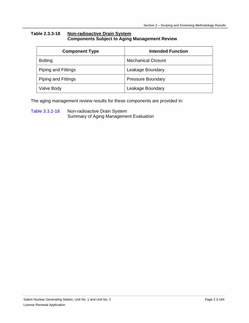
Section 2 – Scoping and Screening Methodology Results
Salem Nuclear Generating Station, Unit No. 1 and Unit No. 2 Page 2.3-164License Renewal Application
Table 2.3.3-18 Non-radioactive Drain System Components Subject to Aging Management Review
Component Type Intended Function
Bolting Mechanical Closure
Piping and Fittings Leakage Boundary
Piping and Fittings Pressure Boundary
Valve Body Leakage Boundary The aging management review results for these components are provided in: Table 3.3.2-18 Non-radioactive Drain System Summary of Aging Management Evaluation

Section 2 – Scoping and Screening Methodology Results
Salem Nuclear Generating Station, Unit No. 1 and Unit No. 2 Page 2.3-165 License Renewal Application
2.3.3.19 Radiation Monitoring System
System Purpose The Radiation Monitoring System is a normally operating system designed to detect, compute, indicate, annunciate, and record radiation levels at selected locations inside the plant. It also provides interlock signals to support intended functions on high radiation level detection. The Radiation Monitoring System is in scope for license renewal. The Radiation Monitoring System has interfaces with several other systems and components that are not within the license renewal boundary of the Radiation Monitoring System, and are evaluated separately. These include the Auxiliary Building Ventilation, Chemical and Volume Control, Circulating Water, Component Cooling, Containment Ventilation, Control Area Ventilation, Fuel Handling Ventilation System, Heating Water and Heating Steam, Main Condenser and Air Removal, Main Steam, Non-radioactive Liquid Waste, Radwaste Systems, Service Water, and the Steam Generators. The purpose of the Radiation Monitoring System is to detect, compute, indicate, annunciate, and record radiation levels at selected locations inside the plant. The Radiation Monitoring System accomplishes this purpose by providing process, process filter, and area radiation monitors. It also provides interlock signals to support intended functions on high radiation level detection. The process monitors consist of the control room air intake duct, containment air particulate, containment noble gas, containment iodine, containment fan cooler radiation, condenser air removal, component cooling liquid, waste disposal system liquid effluent, steam generator blowdown liquid, letdown line, evaporator and feed preheaters condensate, non-radioactive liquid waste basin, plant vent effluent, plant vent high range, and main steam line. The containment fan cooler process radiation monitors have been replaced by the process radiation monitors located at the stilling wells of the circulating water system. The control room air intake duct radiation monitor is a safety-related monitor that initiates the isolation and pressurization of the control area envelope. The containment air particulate, noble gas, and iodine monitors are safety-related and signal to isolate the containment purge and vacuum/pressure relief valves upon receipt of a high radiation condition. The waste disposal system liquid effluent monitor is a safety-related monitor and signals to isolate the waste disposal system liquid releases upon receipt of a high radiation condition. The containment high range radiation monitors are safety-related monitors. The condenser air removal radiation monitors do not monitor liquids and do not support intended functions, and their failure would not prevent safety-related equipment from performing their safety-related functions. The plant vent radiation monitors are nonsafety-related and are connected to the plant vent. The main steam line high range radiation monitors safety-related monitors that are externally mounted adjacent to the main steam lines in the Penetration Areas.

Section 2 – Scoping and Screening Methodology Results
Salem Nuclear Generating Station, Unit No. 1 and Unit No. 2 Page 2.3-166 License Renewal Application
The main steam N16 radiation monitors are externally mounted adjacent to the main steam lines and are nonsafety-related and perform no intended functions. The component cooling liquid, steam generator blowdown liquid, letdown line, evaporator and feed preheaters condensate, and non-radioactive liquid waste basin process radiation monitors and their associated piping and piping components are not included in the scope of the Radiation Monitoring System, and are evaluated with the license renewal system associated with the process liquid (i.e., Chemical and Volume Control, Circulating Water, Component Cooling, Non-radioactive Waste Liquid, and Radwaste). The process filter radiation monitors are all nonsafety-related, and consist of the reactor coolant filter and condensate filter (polishers) (R40) monitors. They do not support intended functions and their failure would not prevent safety-related equipment from performing their safety-related functions. The area radiation monitors consists of the control room area, containment area low range, radiochemistry laboratory, charging pump room, fuel handling building area, primary sample lab, incore seal table, fuel storage area, containment personnel hatches, chemistry counting room, control point, fuel handling cranes, mechanical penetration area, containment high range, electrical penetration, the Technical Support Center, and the post-accident sampling room. The fuel handling building area monitor is a safety-related monitor that signals to re-align the fuel handling building ventilation through charcoal filter units. For Unit 2, high radiation detection in either the fuel handling area, or the fuel storage area actuates the fuel handling ventilation system exhaust fans. The containment high range area monitors are safety-related monitors. The control room area, containment area low range, radiochemistry laboratory, charging pump room, primary sample lab, incore seal table, containment personnel hatches, chemistry counting room, control point, fuel handling cranes, mechanical penetration area, containment high range accident, electrical penetration, and the post-accident sampling room area radiation monitors do not support intended functions, and their failure would not prevent safety-related equipment from performing their safety-related functions. System Operation The Radiation Monitoring System is comprised of radiation monitors, tubes, pumps, piping, and piping components. The process radiation monitors are either in-stream, use process pressure, or an external sampling pump to receive, filter, analyze, and discharge the sample back to the process or originating environment. The control room air intake duct monitors continuously monitor the air entering the control room envelope and use scintillation detectors. Upon receipt of a high radiation signal, the control room intake duct isolates, and the control area ventilation system is placed into pressurization mode.
Section 2 – Scoping and Screening Methodology Results
Salem Nuclear Generating Station, Unit No. 1 and Unit No. 2 Page 2.3-167 License Renewal Application
The containment particulate, noble gas, and iodine monitors use a pump to pull samples into a sealed compartment for the triple analysis. The monitors are scintillation detectors, and if high radiation is detected by either the noble gas or iodine detectors, the monitor signals the containment ventilation system to isolate. The particulate detector is used to monitor reactor coolant system leakage during modes 1 through 4. The component cooling liquid monitors uses scintillation detectors to continuously monitor the component cooling water system. A high radiation level signals for a closure of the component cooling system surge tank vent valve. The waste disposal system liquid effluent monitor uses a scintillation detector and monitors all liquid releases. A high radiation level signals the plant radioactive waste discharge valve to close. The steam generator blowdown liquid monitor uses a scintillation detector and monitors the blowdown. A high radiation level signals the steam generator blowdown valves to close. For Unit 1 only, the evaporator and feed preheaters condensate lines are monitored using a scintillation detector. A high radiation level signals the heating water and heating steam system condensate lines to isolate. The non-radioactive liquid waste system has an effluent monitor that uses a scintillation detector. A high radiation level signal trips the groundwater remediation pumps. The plant vent effluent monitor has four channels; low, intermediate, and high range noble gas, and gaseous effluent. Normally, only the low range sample pumps operate, and if the detector reaches its setpoint, the intermediate and high range pumps operate. A high radiation level on the fourth channel isolates the containment ventilation system and the waste gas discharge valve. The plant vent high range monitors sample and detect noble gases discharged through the plant vent during accident conditions. During normal operations, other sampling equipment is used in the sample flowpath to pull containment samples for routine analyses. The condenser air removal, letdown line, and main steam line process radiation monitors indicate and alarm upon receipt of a high radiation level, and do not perform any actuation. The circulating water system stilling well radiation monitors that monitor service water for radiation leakage as the former containment fan cooler radiation monitors also indicate and alarm upon receipt of a high radiation level, and do not perform any actuation. The process filter monitors for the reactor coolant filters and condensate filters (polishers) are mounted externally to the filters. The monitors have provisions for local radiation indication and alarm. The radiation levels are administratively tracked to determine the replacement frequency of the process filter or media. High radiation alarms annunciate in the control room. The area radiation monitors consist of gamma-sensitive Geiger-Mueller or ion chamber detectors. The fuel handling building area radiation monitor and fuel storage area radiation monitor continuously monitor the fuel storage areas. A high radiation alarm signals alignment of the fuel handling building ventilation through charcoal filter units. For Unit 2, high radiation detection in either the fuel handling area, or the fuel storage area actuates the fuel handling ventilation system exhaust fans.
Section 2 – Scoping and Screening Methodology Results
Salem Nuclear Generating Station, Unit No. 1 and Unit No. 2 Page 2.3-168 License Renewal Application
The fuel handling crane area radiation monitors continuously monitor the fuel pool storage area. A high radiation alarm locks out all crane motion other than the downward movement of the suspended load. Only local indication is provided. No remote indication or alarm is forwarded to the control room. The control room area, containment area low range, containment area high range, radiochemistry laboratory, charging pump room, primary sample lab, incore seal table, containment personnel hatches, chemistry counting room, mechanical penetration area, electrical penetration radiation monitors continuously monitor their respective area, and provide alarms in the control room. The control point and post-accident sampling room area radiation monitors continuously monitor their respective area, and provide local alarms. These radiation monitors have no control function or interlock. For more detailed information, see UFSAR Section 5.2.7, 9.4.1, 11.2, 11.3, and 11.4.1. System Boundary The Radiation Monitoring System boundary begins at the interface with the auxiliary building exhaust system discharge, continues through the plant vent effluent radiation monitor, and ends at the auxiliary building exhaust system discharge. The boundary also includes the flowpath that begins at the containment radiation monitoring system piping, continues through the containment radiation monitors, and ends in the containment atmosphere. The license renewal boundary also includes the following monitors; the control room air intake duct monitor, the waste disposal system liquid effluent monitor, the containment area high range, the plant vent high range monitors, the fuel handling building area monitor, and the fuel storage area monitor. The Radiation Monitoring System scoping boundary also includes the pressure retaining portions of Radiation Monitoring System instrumentation and its associated piping, tubing, and instrumentation root valves. Also included in the license renewal scoping boundary of the Radiation Monitoring System are those portions of nonsafety-related piping and equipment that extend beyond the safety-related/nonsafety-related interface up to the location of the first seismic anchor, or to a point no longer in proximity to equipment performing a safety-related function, whichever extends furthest. This includes the nonsafety-related portions of the system connecting to the Auxiliary Building Ventilation System, shown in red. Included in this boundary are pressure retaining components relied upon to preserve the leakage boundary intended function of this portion of the system. For more information, refer to the license renewal boundary drawing for identification of this boundary, shown in red. Not included in the scope of license renewal are the following radiation monitors; condenser air removal, component cooling liquid, steam generator blowdown liquid, letdown line, evaporator and feed preheaters condensate, non-radioactive liquid waste basin, main steam line, reactor coolant filter, condensate filter (polishers), control room area, containment area low range, radiochemistry laboratory, charging pump room, primary sample lab, incore seal table, containment personnel hatches, chemistry counting room, control point, fuel handling cranes, mechanical penetration area, electrical penetration, the Technical Support Center, and the post-accident sampling room area radiation monitors.

Section 2 – Scoping and Screening Methodology Results
Salem Nuclear Generating Station, Unit No. 1 and Unit No. 2 Page 2.3-169 License Renewal Application
Not included in the Radiation Monitoring System license renewal scoping boundary are the following interfacing systems, which are separately evaluated as license renewal systems: Auxiliary Building Ventilation System Chemical and Volume Control System Circulating Water System Component Cooling System Containment Ventilation System Control Area Ventilation System Fuel Handling Ventilation System Heating Water and Heating Steam System Main Condenser and Air Removal System Main Steam Non-radioactive Liquid Waste System Radwaste System Steam Generators Reason for Scope Determination The Radiation Monitoring System is in scope under 10 CFR 54.4(a)(1) because portions of the system are safety-related or relied upon to remain functional during and following design basis events. The Radiation Monitoring System is in scope under 10 CFR 54.4(a)(2) because failure of nonsafety-related portions of the system would prevent satisfactory accomplishment of function(s) identified for 10 CFR 54.4(a)(1). It also meets 10 CFR 54.4(a)(3) because it is relied upon in safety analyses or plant evaluations to perform a function that demonstrates compliance with the Commission's regulations for Environmental Qualification (10 CFR 50.49). The Radiation Monitoring System is not relied upon in safety analyses or plant evaluations to perform a function that demonstrates compliance with the Commission's regulations for Fire Protection (10 CFR 50.48), Pressurized Thermal Shock (10 CFR 50.61), Anticipated Transients Without Scram (10 CFR 50.62), or Station Blackout (10 CFR 50.63). System Intended Functions 1. Sense process conditions and generate signals for reactor trip or engineered safety features actuation. The Radiation Monitoring System isolates the control area ventilation system on a high radiation condition. 10 CFR 54.4(a)(1) 2. Provide primary containment boundary. The Radiation Monitoring System has containment isolation valves that actuate upon a Phase A containment isolation signal. 10 CFR 54.4(a)(1) 3. Resist nonsafety-related SSC failure that could prevent satisfactory accomplishment of a safety-related function. The Radiation Monitoring System has the potential for spatial interaction with safety-related components. 10 CFR 54.4(a)(2). 4. Relied upon in safety analyses or plant evaluations to perform a function that demonstrates compliance with the Commission's regulations for Equipment Qualification (10 CFR 50.49). The Radiation Monitoring System contains several EQ components. 10 CFR 54.4(a)(3)

Section 2 – Scoping and Screening Methodology Results
Salem Nuclear Generating Station, Unit No. 1 and Unit No. 2 Page 2.3-170 License Renewal Application
UFSAR References 5.2.7 6.4.2.2 9.4.1 11.2 11.3 11.4 License Renewal Boundary Drawings Unit 1: LR-205237 Sheet 1 LR-205238 Sheet 1 Unit 2: LR-205337 Sheet 1 LR-205338 Sheet 1 Unit Common: None

Section 2 – Scoping and Screening Methodology Results
Salem Nuclear Generating Station, Unit No. 1 and Unit No. 2 Page 2.3-171 License Renewal Application
Table 2.3.3-19 Radiation Monitoring System Components Subject to Aging Management Review
Component Type Intended Function
Bolting Mechanical Closure
Filter Housing Pressure Boundary
Flow Element Pressure Boundary
Piping and Fittings Pressure Boundary
Pump Casing (all sample pumps for R11/R12, R41, and R45)
Pressure Boundary
Thermowell Pressure Boundary
Valve Body Pressure Boundary The aging management review results for these components are provided in: Table 3.3.2-19 Radiation Monitoring System Summary of Aging Management Evaluation

Section 2 – Scoping and Screening Methodology Results
Salem Nuclear Generating Station, Unit No. 1 and Unit No. 2 Page 2.3-172 License Renewal Application
2.3.3.20 Radioactive Drain System
System Purpose The Radioactive Drain System is a mechanical normally operating system designed to provide contaminated drainage control and management for the Auxiliary Building, Containment Structure, Penetration Areas, and the Fuel Handling Building, provide flood protection for equipment in the Auxiliary and Fuel Handling Buildings, and provide flowpaths from various safety-relief valves to the Radwaste System. The Radioactive Drain System is in scope for license renewal. The Radioactive Drain System has interfaces with several other systems and components that are not within the license renewal boundary of the Radioactive Drain System, and are evaluated separately. These include the Auxiliary Building Ventilation, Auxiliary Feedwater, Chemical and Volume Control, Component Cooling, Containment Spray, Radwaste, Reactor Coolant, Residual Heat Removal, Safety Injection, Sampling, and Spent Fuel Cooling Systems, and the Steam Generators. The purpose of the Radioactive Drain System is to collect and forward miscellaneous drainage from buildings and equipment, and safety-relief valve discharges to the Radwaste System. The Radioactive Drain System accomplishes this purpose by providing drains, drain flowpaths, pumps, and discharge flowpaths from buildings and equipment, including safety-relief valve discharges, to the Radwaste System. The Radwaste System contains the containment isolation valves that are downstream of the Radioactive Drain System and Radwaste System interface. Therefore, the intended function of the provision of containment isolation boundary resides with the Radwaste System. System Operation The Radioactive Drain System is comprised of sump pumps, piping, and piping components. The Auxiliary Building contains the residual heat removal sumps. Floor drains from the Penetration Areas also flow to the residual heat removal sumps. The Containment Structure has the reactor sump located directly under the reactor vessel, the containment sump that is divided between the emergency core cooling system portion and the radioactive drain portion, and inner and outer trench drains that run circumferentially in the Containment Structure at elevation 78-feet. The Fuel Handling Building has a fuel handling area sump. Under normal operations, internal building and equipment drains flow by gravity to sumps and trenches, where the Radioactive Drain System sump pumps forward collected drainage to the waste hold-up tanks in the Radwaste System. The containment isolation valves are part of the Radwaste System, therefore, the Radioactive Drains System does not have a containment isolation function. During an accident condition, when the Residual Heat Removal System may be aligned to take suction from the containment sump, the containment sump level instrumentation provides a readout in the control room for operators to take manual actions such as to swap over to recirculation.

Section 2 – Scoping and Screening Methodology Results
Salem Nuclear Generating Station, Unit No. 1 and Unit No. 2 Page 2.3-173 License Renewal Application
All of the Radioactive Drains System sump pumps are powered by non-vital buses, and are not actuated during a design basis accident. For more detailed information, see UFSAR Sections 3.4.3.1, 6.3.5.4, and 9.3.3. System Boundary The Radioactive Drain System boundary begins at the floor drains of the Auxiliary Building and Penetration Areas, and terminates at the residual heat removal sumps. Within this scoping boundary are the various Auxiliary Building equipment drains that flow from pumps, pump baseplates, condensate drip pans, valve stem leak-offs, safety-relief valve discharges, and tanks that begin at their respective interface with the component, and drain to the residual heat removal sumps. The boundary continues from the residual heat removal sump pumps and discharge piping and ends at the inlet isolation valves to the waste hold-up tanks. The residual heat removal sumps are evaluated with the Auxiliary Building. The waste hold-up tanks are evaluated with the Radwaste System. The Radioactive Drain System boundary also begins at the floor and polar crane rail drains of the Containment Structure, and terminates at the containment sump. The boundary includes the containment sump pumps and discharge piping that ends at the waste liquid system inboard containment isolation valve that is evaluated with the Radwaste System. The containment sump is evaluated with the Containment Structure. The boundary also includes floor drains that flow to the reactor sump, and the inner and outer trenches that flow to the reactor sump. The boundary continues with the suction of the reactor sump pumps through their discharge piping, and ends at the inlet isolation valves to the waste hold-up tanks. The reactor sump, and inner and outer drain trench are evaluated with the Containment Structure. The boundary does not include the imbedded piping between the inner and outer drain trenches. The boundary includes the discharges from chemical and volume control, residual heat removal, and safety injection safety-relief valves flow and ends at the outer drain trench. The boundary does not include the imbedded piping from the outlet drain trench to the containment sump. The outer drain trench and containment sump are evaluated with the Containment Structure. The scoping boundary also includes the reactor coolant pump oil lift pump oil and water separators and associated piping and components. Also included in the boundary are the reactor coolant drain tank drains and its safety-relief valve discharge piping that terminates at the reactor sump. The reactor sump is evaluated with the Containment Structure. The Radioactive Drain System boundary also begins at the floor drains of the Fuel Handling Building, and continues to the fuel handling building area sump. Also included in this scoping boundary are the drains that flow from the spent fuel pit skimmer filter pump and strainer to the fuel handling area sump. The boundary continues from the fuel handling building area sump pump, through its discharge piping, and ends at the inlet isolation valves to the waste hold-up tanks. The waste hold-up tanks are evaluated with the Radwaste System. The fuel handling building area sump is evaluated with the Fuel Handling Building.
Section 2 – Scoping and Screening Methodology Results
Salem Nuclear Generating Station, Unit No. 1 and Unit No. 2 Page 2.3-174License Renewal Application
The seismic gap drain line between the Fuel Handling Building and Penetration Area is also included in the scoping boundary. The boundary also begins at the decontamination shower room and ends at the inlet isolation valves at the laundry and hot shower tanks. The laundry and hot shower tanks are evaluated with the Radwaste System. All associated piping, components, and instrumentation contained within the flowpaths described above are included in the system evaluation boundary. The reactor sump and containment sump level instrumentation are also included in the evaluation boundary. Also included in the license renewal scoping boundary of the Radioactive Drain System are those portions of nonsafety-related piping and equipment that extend beyond the safety-related or nonsafety-related interface up to the location of the first seismic anchor, or to a point no longer in proximity to equipment performing a safety-related function, whichever extends furthest. Included in this boundary are pressure retaining components relied upon to preserve the leakage boundary intended function of this portion of the system. This includes the nonsafety-related portions of the systems located within the Auxiliary Building, Containment Structure, Fuel Handling Building, and the Penetration Areas, shown in red. Portions of the Radioactive Drain System embedded in floors are not required to support the system's leakage boundary intended functions, therefore, these components are not included in the scope of license renewal. Also not included in the scope of license renewal are the portions of the Radioactive Drain System such as sumps, trenches, and valve pits that are evaluated with the respective building. Not included in the Radioactive Drain System license renewal scoping boundary are the following interfacing systems, which are separately evaluated as license renewal systems: Auxiliary Building Ventilation System Auxiliary Feedwater System Chemical and Volume Control System Component Cooling System Containment Spray System Radwaste System Reactor Coolant System Residual Heat Removal System Safety Injection System Sampling System Spent Fuel Cooling System Steam Generators Reason for Scope Determination The Radioactive Drain System is in scope under 10 CFR 54.4(a)(1) because portions of the system are safety-related or relied upon to remain functional during and following design basis events. The Radioactive Drain System is in scope under 10 CFR 54.4(a)(2) because failure of nonsafety-related portions of the system would prevent satisfactory accomplishment of

Section 2 – Scoping and Screening Methodology Results
Salem Nuclear Generating Station, Unit No. 1 and Unit No. 2 Page 2.3-175License Renewal Application
function(s) identified for 10 CFR 54.4(a)(1). It also meets 10 CFR 54.4(a)(3) because it is relied upon in safety analyses or plant evaluations to perform a function that demonstrates compliance with the Commission's regulations for Fire Protection (10 CFR 50.48) and Environmental Qualification (10 CFR 50.49). The Radioactive Drain System is not relied upon in safety analyses or plant evaluations to perform a function that demonstrates compliance with the Commission's regulations for Pressurized Thermal Shock (10 CFR 50.61), Anticipated Transients Without Scram (10 CFR 50.62), or Station Blackout (10 CFR 50.63). System Intended Functions 1. Sense process conditions and generate signals for reactor trip or engineered safety features actuation. The Radioactive Drain System contains the containment sump level instrumentation that provides containment building water level indication to the control room during accident conditions. 10 CFR 54.4(a)(1) 2. Resist nonsafety-related SSC failure that could prevent satisfactory accomplishment of a safety-related function. The Radioactive Drain System has the potential for spatial interaction with safety-related components, and to provide (a)(2) functional support to preclude flooding in rooms of the Auxiliary Building that contain safety-related equipment. The Radioactive Drain System also provides structural support to safety-related piping and components. 10 CFR 54.4(a)(2). 3. Relied upon in safety analyses or plant evaluations to perform a function that demonstrates compliance with the Commission's regulations for Fire Protection (10 CFR 50.48). The Radioactive Drain System provides adequate drainage to protect safety-related equipment during internal flooding caused by a fire protection system discharge. 10 CFR 54.4(a)(3) 4. Relied upon in safety analyses or plant evaluations to perform a function that demonstrates compliance with the Commission's regulations for Equipment Qualification (10 CFR 50.49). The Radioactive Drain System contains several EQ components, including the containment sump level indication. 10 CFR 54.4(a)(3) UFSAR References 3.4.3.1 3.6.5 6.3.2.2 6.3.5.4 9.3.3 License Renewal Boundary Drawings Unit 1: LR-205201 Sheet 1 LR-205225 Sheet 1 LR-205225 Sheet 2 LR-205226 Sheet 1 LR-205226 Sheet 2 LR-205227 Sheet 1 LR-205227 Sheet 2
Section 2 – Scoping and Screening Methodology Results
Salem Nuclear Generating Station, Unit No. 1 and Unit No. 2 Page 2.3-176License Renewal Application
LR-205227 Sheet 3 LR-205228 Sheet 1 LR-205228 Sheet 2 LR-205229 Sheet 1 LR-205229 Sheet 2 LR-205229 Sheet 3 LR-205230 Sheet 1 LR-205232 Sheet 1 LR-205232 Sheet 2 LR-205233 Sheet 1 LR-205234 Sheet 1 LR-205234 Sheet 2 LR-205234 Sheet 3 LR-205235 Sheet 1 LR-205236 Sheet 1 LR-205239 Sheet 1 LR-205239 Sheet 2 LR-205239 Sheet 3 LR-205239 Sheet 4 LR-205239 Sheet 5 LR-205240 Sheet 2 LR-205242 Sheet 3 LR-205242 Sheet 4 LR-205244 Sheet 1 LR-205244 Sheet 2 Unit 2: LR-205301 Sheet 1 LR-205325 Sheet 1 LR-205325 Sheet 2 LR-205326 Sheet 1 LR-205326 Sheet 2 LR-205327 Sheet 1 LR-205327 Sheet 2 LR-205327 Sheet 3 LR-205328 Sheet 1 LR-205328 Sheet 2 LR-205329 Sheet 1 LR-205329 Sheet 2 LR-205329 Sheet 3 LR-205330 Sheet 1 LR-205332 Sheet 1 LR-205332 Sheet 2 LR-205333 Sheet 1 LR-205334 Sheet 1 LR-205334 Sheet 2 LR-205334 Sheet 3 LR-205335 Sheet 1 LR-205336 Sheet 1 LR-205337 Sheet 1
Section 2 – Scoping and Screening Methodology Results
Salem Nuclear Generating Station, Unit No. 1 and Unit No. 2 Page 2.3-177 License Renewal Application
LR-205339 Sheet 1 LR-205339 Sheet 2 LR-205339 Sheet 3 LR-205340 Sheet 2 LR-205342 Sheet 3 LR-205342 Sheet 4 LR-205344 Sheet 1 LR-205344 Sheet 2 Unit Common: None
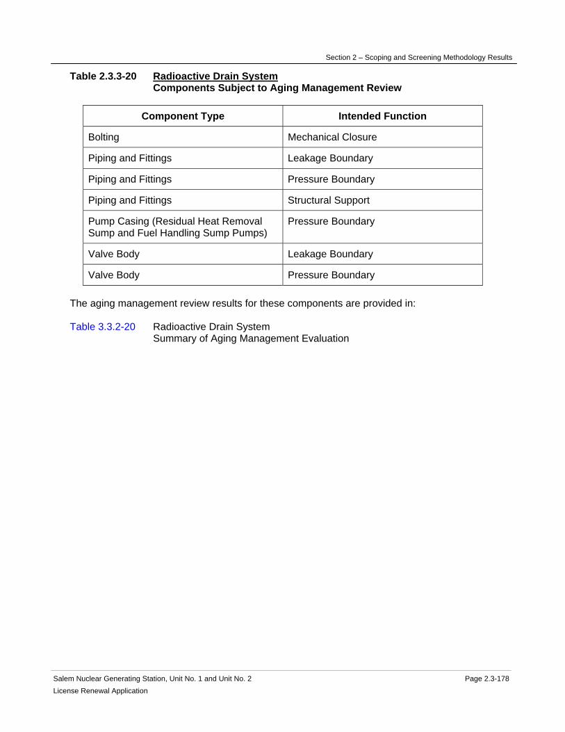
Section 2 – Scoping and Screening Methodology Results
Salem Nuclear Generating Station, Unit No. 1 and Unit No. 2 Page 2.3-178 License Renewal Application
Table 2.3.3-20 Radioactive Drain System Components Subject to Aging Management Review
Component Type Intended Function
Bolting Mechanical Closure
Piping and Fittings Leakage Boundary
Piping and Fittings Pressure Boundary
Piping and Fittings Structural Support
Pump Casing (Residual Heat Removal Sump and Fuel Handling Sump Pumps)
Pressure Boundary
Valve Body Leakage Boundary
Valve Body Pressure Boundary The aging management review results for these components are provided in: Table 3.3.2-20 Radioactive Drain System Summary of Aging Management Evaluation

Section 2 – Scoping and Screening Methodology Results
Salem Nuclear Generating Station, Unit No. 1 and Unit No. 2 Page 2.3-179 License Renewal Application
2.3.3.21 Radwaste System
System Purpose The Radwaste System is a normally-operating mechanical system designed to provide the equipment necessary to collect, process, and prepare radioactive liquid, gaseous, and solid wastes for disposal. The Radwaste System consists of the following four plant systems associated with the processing of radioactive waste products: the boron recovery system, the waste liquid (radioactive) system, the waste gas (radioactive) system, and the waste solid (radioactive) system. The Radwaste System is designed to meet or exceed the applicable federal and state regulations for the containment, control, and release or disposal of radioactive liquids, gases, and solids generated as a result of normal and emergency plant operation. The Radwaste System is in scope for license renewal and interfaces with the Radioactive Drain System and Reactor Coolant System inside the Containment Structure. The primary purpose of the Radwaste System is to manage the collection and processing of the liquid waste and gaseous waste from the Reactor Coolant System. The liquid and gaseous wastes are collected from the Reactor Coolant System in the pressurizer relief tank (evaluated in the Reactor Coolant System) and reactor coolant drain tank during normal and emergency plant operation. Additionally, borated water is removed by the Chemical & Volume Control System during normal operation to allow dilution of the Reactor Coolant System. This excess water and other contaminated water from the drains and sumps is eventually processed as wastewater through a portable demineralizer for discharge to the river. The Radwaste System accomplishes its purpose with a variety of tanks, piping, and piping components. Both the waste liquid and waste gas systems have containment isolation valves that close on a signal from the Reactor Protection System. The waste gas portion of the system contains the gaseous vent header, the waste gas compressors, and the waste gas decay tanks with associated piping and valves for short-term storage of the gas until the short-lived fission products decay to an acceptable level for release to the plant vent. The waste gas system also supplies high pressure nitrogen to the safety injection accumulators and service water accumulators. This system also supplies low pressure hydrogen to the volume control tank for maintaining oxygen levels in the Reactor Coolant System at acceptable concentrations. The waste gas analyzer monitors the oxygen level of the various tanks in this system and the Chemical and Volume Control System to ensure compliance with the license conditions. The waste liquid portion of the Radwaste System includes two separate evaporator packages on each unit: the boric acid evaporator and the waste evaporator. The boron recovery system contains the boric acid evaporator with three heat exchangers (boric acid distillate cooler, boric acid vent condenser, and boric acid evaporator condenser) that are cooled by the Component Cooling System. However, these components have been isolated manually from the Component Cooling System for an extended period of time and are not required to mitigate the consequences of an accident. The waste evaporator also contains three heat exchangers (waste evaporator subcooler, waste evaporator vent gas cooler, and waste evaporator vent condenser) that are cooled by the Component Cooling System. These components have also been isolated manually from the Component Cooling System for an extended period of time and are not required to mitigate the consequences of an accident. The waste solid portion of the Radwaste System provides for the packaging of radioactive solid waste and processing of contaminated resins and liquid waste for transportation to an

Section 2 – Scoping and Screening Methodology Results
Salem Nuclear Generating Station, Unit No. 1 and Unit No. 2 Page 2.3-180 License Renewal Application
offsite processor or to the ultimate disposal site. Resins are sluiced from the various demineralizers in the Auxiliary Building to the spent resin storage tank, and are transferred to the waste solid area for shipment. Also, when potentially contaminated oil is drained from the emergency core cooling pumps for maintenance, this oil is collected manually in the waste solid area for shipment to offsite processing. The equipment associated with the original waste solid system has been abandoned in place, and is not in scope for license renewal. System Operation The Radwaste System consists of the following four plant systems associated with the processing of waste products: the boron recovery system, the waste liquid (radioactive) system, the waste gas (radioactive) system, and the waste solid (radioactive) system. The boron recovery portion of the Radwaste System consists mainly of the components associated with the boric acid evaporator. This part of the system contains the following components: the concentrates holding tank and transfer pumps, the concentrates filter, the boric acid concentrates pumps, the feed pre-heater, the gas stripper, the boric acid evaporator and evaporation chamber, the absorption tower, the evaporator condenser, the vent condenser, and the distillate cooler and pumps. The boric acid evaporator vent condenser, evaporator condenser and distillate cooler, which are connected to the Component Cooling System, have been removed from service for an extended period of time, and are not credited for any design basis event. The main components of the boric acid evaporator have been out of service but are in scope for license renewal for leakage boundary. The gas stripper feed pumps, boric acid evaporator feed ion exchangers, and ion exchange filter are periodically used for cleanup of the Chemical & Volume Control System holdup tanks, which are evaluated separately with the Chemical & Volume Control System. The waste liquid system provides for the collection, containment and processing of miscellaneous liquid waste for reuse, release, or disposal. This portion of the Radwaste System contains the following components: reactor coolant drain tank and pumps, the waste monitor tanks and pumps, the auxiliary building sump tank and pumps, the laundry and hot shower tanks and pump, the chemical drain tank and pump, the reagent tank, waste holdup tanks, the waste evaporator feed pump, the waste monitor holdup tank and pump, the spent resin storage tank, the Chemical & Volume Control System monitor tanks and pumps, and the waste evaporator package (liquid side). The waste liquid system provides service functions to the Reactor Coolant System including: chemical and volume control for the Reactor Coolant System, pressurizer relief tank waste liquid containment and collection; and spent fuel pool water processing during refueling. The waste liquid system also provides the following additional functions: miscellaneous waste processing (radioactive laboratory drains, building and equipment drains, and discharge of spent resins from demineralizers), radioactive shower drain waste processing, and chemical waste processing, and release of radioactive liquid wastes. In addition to the boric acid evaporator, there is also a waste evaporator that consists of the following components: feed preheater, heater, distillate subcooler, distillate vent condenser, vent gas cooler, concentrate transfer pumps, distillate pumps, feed pumps, recirculation pump, distillate pot, entrainment separator, and vapor body. Both evaporators have been removed from service for an extended period of time, and are not required to satisfy any design basis functions. Water is processed from the waste holdup tanks and the Chemical & Volume Control System holdup tanks through a portable demineralizer. The effluent from the demineralizer is used to fill the Chemical and Volume Control System monitor tanks, where it is sampled, analyzed,

Section 2 – Scoping and Screening Methodology Results
Salem Nuclear Generating Station, Unit No. 1 and Unit No. 2 Page 2.3-181 License Renewal Application
and released through the Service Water System to the Delaware River. If high radioactivity is detected in the effluent during the liquid release to the river, the isolation valve is automatically closed by the Radiation Monitoring System. The waste liquid system also provides the collection of water from the reactor coolant pump seal leakage and standpipe, reactor vessel o-ring leakage, and draining of the pressurizer relief tank and safety injection accumulators to the reactor coolant drain tank during normal plant operation. The reactor coolant drain tank has containment isolation valves on its gas and liquid spaces that automatically isolate on signals from the Reactor Protection System. The waste gas system provides for the collection, storage, and processing of radioactive gases from all the tanks associated with the servicing of the Reactor Coolant System and the Chemical & Volume Control System. This portion of the Radwaste System provides low-pressure nitrogen gas to the pressurizer relief tank and reactor coolant drain tank and low-pressure hydrogen gas on the volume control tank to maintain the cover gas mixture in these tanks below the required license limit for oxygen. Oxygen concentrations on these tanks are monitored by the waste gas analyzer. The waste gas system also provides high-pressure nitrogen to the safety injection accumulators and service water accumulators. All of the containment isolation valves through the Containment Structure to the reactor coolant drain tank receive a containment isolation signal to close from the Reactor Protection System. The Waste Gas System consists of two waste gas compressors and four waste gas decay tanks in the Auxiliary Building. As the gas tanks are filled, they are placed in holdup to allow for the radioactive decay, and finally released through the plant vent. If high radioactivity is detected in the effluent during the gas release to the vent stack, the isolation valve is automatically closed by the Radiation Monitoring System. The waste solid system provides for the packaging of radioactive solid and concentrated liquid wastes for transportation to an offsite processor or to the ultimate disposal site. This system also includes equipment for baling, transferring, and compacting solid radioactive waste. There are three general types of waste that are shipped from the site as solid waste: spent resin beads, dry compacted trash, and radioactive waste oil. The equipment associated with the waste solid system has been removed from service for an extended period of time and does not perform an intended function. This portion of the system is in its own enclosed area of the Auxiliary Building such that its failure would not affect any safety-related equipment. The waste solid system is not in scope for license renewal. For more detailed information, see UFSAR section 11.2, 11.3, 11.5. System Boundary The waste liquid portion of the Radwaste System boundary begins at the reactor coolant drain tank and continues through the reactor coolant drain tank pumps to the containment penetrations. The boundary in the Containment Structure includes the piping drains from the reactor coolant pump seals and head tanks, Reactor Vessel flange leakoff line, Reactor Coolant System cold leg drains, and the safety injection accumulators. From the containment isolation valves, the piping continues to the Chemical & Volume System holdup tanks isolation valve, refueling water storage tank isolation valve, and to the waste holdup tanks. From the Chemical & Volume Control System holdup tanks, water is recirculated through the gas stripper feed pumps and evaporator feed demineralizers for cleanup or transferred to the spent fuel pool for makeup (evaluated with the Chemical & Volume Control System). The boundary also includes the resin sluice piping from the primary plant demineralizers (mixed bed, cation,

Section 2 – Scoping and Screening Methodology Results
Salem Nuclear Generating Station, Unit No. 1 and Unit No. 2 Page 2.3-182 License Renewal Application
deborating) into the spent resin storage tank. The boundary includes the piping coming from the plant drains, the auxiliary building sump tank, the laundry and hot shower tanks, and the chemical drain tank entering the waste holdup tanks or waste monitor holdup tank for processing. The boundary includes the piping from the waste holdup tanks to the portable demineralizer and back to the Chemical & Volume Control System monitor tanks. This boundary continues from the Chemical & Volume Control System monitor tanks through the monitor tank pumps and ends at the Service Water System isolation valve. The components associated with the boric acid evaporator and the waste evaporator are in scope for license renewal due to leakage boundary. The waste gas portion of the Radwaste System begins at the reactor coolant drain tank and pressurizer relief tank cover gas space and continues through the containment isolation valves and ends at the Auxiliary Building vent gas header and the instrument tubing to the waste gas analyzer. From the vent gas header, the piping through the compressors is included through the waste gas decay tanks to the plant vent stack. The waste gas portion of the Radwaste System excludes the nitrogen bottles and the piping as well as the high-pressure nitrogen and low-pressure hydrogen system from portable tanker trailers. The waste gas components located outside the Auxiliary Building are not in scope for license renewal. There are also two liquid nitrogen tanks located outside the Auxiliary Building, which are not in scope for license renewal. The waste solid portion of the Radwaste System is not safety-related and is separated from any safety-related equipment in the Auxiliary Building. Since the equipment has been removed from service for an extended period of time and does not provide any design basis functions, the waste solid portion of the system is not in scope for license renewal. Also included in the license renewal scoping boundary of the Radwaste System are those portions of nonsafety-related piping and equipment that extend beyond the safety-related and nonsafety-related interface up to the location of the first seismic anchor, or to a point no longer in proximity to equipment performing a safety-related function, whichever extends furthest. This includes the nonsafety-related portions of the system located within the Containment Structure and Auxiliary Building. Included in this boundary are pressure-retaining components relied upon to preserve the leakage boundary intended function of this portion of the system. For more information, refer to the license renewal boundary drawing for identification of this boundary, shown in red. Not included in the Radwaste System license renewal scoping boundary are the following interfacing systems, which are separately evaluated as license renewal systems: Auxiliary Building Ventilation System Chemical & Volume Control System Component Cooling System Compressed Air System Demineralized Water System Heating Water and Heating Steam System Radiation Monitoring System Radioactive Drain System Reactor Coolant System Reactor Protection System Sampling System Safety Injection System

Section 2 – Scoping and Screening Methodology Results
Salem Nuclear Generating Station, Unit No. 1 and Unit No. 2 Page 2.3-183 License Renewal Application
Service Water System Spent Fuel Cooling System Reason for Scope Determination The Radwaste System meets 10 CFR 54.4(a)(1) because it is a safety-related system that is relied upon to remain functional during and following design basis events. It meets 10 CFR 54.4(a)(2) because failure of nonsafety-related portions of the system could prevent satisfactory accomplishment of function(s) identified for 10 CFR 54.4(a)(1). It also meets 10 CFR 54.4(a)(3) because the Radwaste System is relied upon to perform a function that demonstrates compliance with the Commission's regulation for Fire Protection (10 CFR 50.48) and Environmental Qualification (10 CFR 50.49). The Radwaste System is not relied upon in any safety analyses or plant evaluations to perform a function that demonstrates compliance with the Commission's regulation for Pressurized Thermal Shock (10 CFR 50.61), Anticipated Transient Without Scram (10 CFR 50.62), or Station Blackout (10 CFR 50.63). System Intended Functions 1. Provide primary containment boundary. The Radwaste System includes containment isolation valves to assure that radioactive material is not inadvertently transferred out of the Containment Structure. 10 CFR 54.4(a)(1) 2. Maintain the dose consequences within the guidelines of 10 CFR 50.67. The Radwaste System includes containment isolation valves to assure that radioactive material is not inadvertently transferred out of the Containment Structure. 10 CFR 54.4(a)(1) 3. Resist nonsafety-related SSC failure that could prevent satisfactory accomplishment of a safety-related function. The Radwaste System contains nonsafety-related water filled lines in the Auxiliary Building that have the potential for spatial interactions (spray or leakage) with safety-related SSCs. 10 CFR 54.4 (a)(2) 4. Relied upon in safety analyses or plant evaluations to perform a function that demonstrates compliance with the Commission's regulations for Fire Protection (10 CFR 50.48). The Radwaste System is used to provide the collection and processing of fluids from the Radioactive Drain System for disposal. 10 CFR 54.4(a)(3) 5. Relied upon in safety analyses or plant evaluations to perform a function that demonstrates compliance with the Commission's regulations for Environmental Qualification (10 CFR 50.49). The Radwaste System provides several indications to the control room for containment isolation following a design basis accident. 10 CFR 54.4(a)(3) UFSAR References 11.2 11.3 11.5 9.3.4.2 License Renewal Boundary Drawings Unit 1:

Section 2 – Scoping and Screening Methodology Results
Salem Nuclear Generating Station, Unit No. 1 and Unit No. 2 Page 2.3-184 License Renewal Application
LR-205201 Sheet 1 LR-205201 Sheet 2 LR-205216 Sheet 1 LR-205216 Sheet 2 LR-205225 Sheet 1 LR-205226 Sheet 2 LR-205228 Sheet 1 LR-205228 Sheet 2 LR-205228 Sheet 3 LR-205229 Sheet 1 LR-205229 Sheet 2 LR-205229 Sheet 3 LR-205230 Sheet 1 LR-205234 Sheet 1 LR-205234 Sheet 4 LR-205235 Sheet 1 LR-205239 Sheet 1 LR-205239 Sheet 2 LR-205239 Sheet 3 LR-205239 Sheet 4 LR-205239 Sheet 5 LR-205240 Sheet 2 LR-205242 Sheet 7 LR-205246 Sheet 1 LR-205246 Sheet 2 Unit 2: LR-205301 Sheet 1 LR-205301 Sheet 2 LR-205301 Sheet 3 LR-205325 Sheet 1 LR-205326 Sheet 2 LR-205328 Sheet 1 LR-205328 Sheet 2 LR-205328 Sheet 3 LR-205329 Sheet 1 LR-205329 Sheet 3 LR-205330 Sheet 1 LR-205334 Sheet 1 LR-205334 Sheet 4 LR-205335 Sheet 1 LR-205339 Sheet 1 LR-205339 Sheet 2 LR-205339 Sheet 3 LR-205340 Sheet 2 LR-205342 Sheet 7 Unit Common: None

Section 2 – Scoping and Screening Methodology Results
Salem Nuclear Generating Station, Unit No. 1 and Unit No. 2 Page 2.3-185License Renewal Application
Table 2.3.3-21 Radwaste System Components Subject to Aging Management Review
Component Type Intended Function
Bolting Mechanical Closure
Eductor Leakage Boundary
Filter Housing Leakage Boundary
Flow Element Leakage Boundary
Heat Exchanger Components (Boric Acid Distillate Cooler)
Leakage Boundary
Heat Exchanger Components (Boric Acid Evaporator Condenser)
Leakage Boundary
Heat Exchanger Components (Boric Acid Evaporator and Evaporation Chamber)
Leakage Boundary
Heat Exchanger Components (Boric Acid Feed Pre-heater)
Leakage Boundary
Heat Exchanger Components (Boric Acid Vent Condenser)
Leakage Boundary
Heat Exchanger Components (Waste Evaporator Feed Pre-Heater)
Leakage Boundary
Heat Exchanger Components (Waste Evaporator Heater)
Leakage Boundary
Heat Exchanger Components (Waste Evaporator Sub Cooler)
Leakage Boundary
Heat Exchanger Components (Waste Evaporator Vent Condenser)
Leakage Boundary
Heat Exchanger Components (Waste Evaporator Vent Gas Cooler)
Leakage Boundary
Heat Exchanger Components (Waste Gas Compressor)
Evaluated with the Component Cooling System
Hoses Leakage Boundary
Piping and Fittings Leakage Boundary
Piping and Fittings Pressure Boundary
Piping and Fittings Structural Support

Section 2 – Scoping and Screening Methodology Results
Salem Nuclear Generating Station, Unit No. 1 and Unit No. 2 Page 2.3-186License Renewal Application
Component Type Intended Function
Pump Casing (Boric Acid Concentrates Holding Tank Transfer)
Leakage Boundary
Pump Casing (Boric Acid Distillate) Leakage Boundary
Pump Casing (CVC Monitor) Leakage Boundary
Pump Casing (Chemical Drain) Leakage Boundary
Pump Casing (Laundry, Hot Shower, Tank Sump)
Leakage Boundary
Pump Casing (Reactor Coolant Drain) Leakage Boundary
Pump Casing (Waste Evaporator Concentrate Transfer)
Leakage Boundary
Pump Casing (Waste Evaporator Distillate)
Leakage Boundary
Pump Casing (Waste Evaporator Feed) Leakage Boundary
Pump Casing (Waste Evaporator Vapor Body Recirculation)
Leakage Boundary
Pump Casing (Waste Monitor Holdup Tank)
Leakage Boundary
Restricting Orifices Leakage Boundary
Sight Glasses Leakage Boundary
Tanks (Auxiliary Building Sump) Leakage Boundary
Tanks (Boric Acid Concentrates Holding) Leakage Boundary
Tanks (Boric Acid Gas Stripper, Absorption Tower)
Leakage Boundary
Tanks (CVC Monitor) Leakage Boundary
Tanks (Chemical Drain) Leakage Boundary
Tanks (Gas Decay) Pressure Boundary
Tanks (Laundry and Hot Shower) Leakage Boundary
Tanks (Reactor Coolant Drain) Leakage Boundary
Tanks (Reagent) Leakage Boundary
Tanks (Spent Resin Storage) Leakage Boundary

Section 2 – Scoping and Screening Methodology Results
Salem Nuclear Generating Station, Unit No. 1 and Unit No. 2 Page 2.3-187 License Renewal Application
Component Type Intended Function
Tanks (Waste Evaporator Distillate Pot) Leakage Boundary
Tanks (Waste Evaporator Entrainment Separator)
Leakage Boundary
Tanks (Waste Evaporator Vapor Body) Leakage Boundary
Tanks (Waste Gas Comp Moisture Separator)
Leakage Boundary
Tanks (Waste Holdup) Leakage Boundary
Tanks (Waste Liquid Radiation Monitor) Leakage Boundary
Tanks (Waste Monitor Holdup) Leakage Boundary
Thermowell Leakage Boundary
Valve Body Leakage Boundary
Valve Body Pressure Boundary
Valve Body Structural Support The aging management review results for these components are provided in: Table 3.3.2-21 Radwaste System Summary of Aging Management Evaluation

Section 2 – Scoping and Screening Methodology Results
Salem Nuclear Generating Station, Unit No. 1 and Unit No. 2 Page 2.3-188 License Renewal Application
2.3.3.22 Sampling System
System Purpose The Sampling System is a normally operating mechanical system designed to obtain liquid and gas samples for laboratory analyses of chemistry and radiochemistry conditions of the Reactor Coolant, Residual Heat Removal, Chemical and Volume Control, Safety Injection, Demineralized Water, Main Condensate and Feedwater, Main Steam, and Steam Generators systems. Samples can be provided under operating conditions from full power to cold shutdown. The Sampling System consists of the following plant systems: Sampling and Post-Accident Sampling. The Salem Generating Station Units 1 and 2 no longer operate the post-accident sampling system as it was removed from the current licensing basis, and it was physically drained and disconnected from the plant. The major components of the Sampling System are heat exchangers, piping, valves, and piping components. The Sampling System is in scope for license renewal. However, portions of the Sampling System are not required to perform an intended function and are not in scope. The Sampling System has interfaces with several other systems and components that are not within the license renewal boundary of the Sampling System, and are evaluated separately. These include the Chemical and Volume Control, Component Cooling, Demineralized Water, Main Condensate and Feedwater, Main Steam, Non-Radioactive Drain, Radioactive Drain, Radwaste, Reactor Coolant, Residual Heat Removal, Safety Injection, and Steam Generators systems. The purpose of the Sampling System is to provide liquid and gas samples from various locations in the plant to designated locations, including online analytical equipment and grab samples for analysis, for purposes of guidance in operation of the Reactor Coolant, Residual Heat Removal, Component Cooling, Chemical and Volume Control, Main Steam, Safety Injection, and Steam Generators systems. The Sampling System accomplishes this purpose by connecting the sampling sources to the sample sinks, sample tanks and vessels, and analyzers. The Sampling System also provides containment isolation. The Sampling System accomplishes this purpose using containment isolation valves that automatically close upon receiving a Phase A containment isolation signal. Under normal operations, samples are either continuously provided to the sample sinks or to the online analyzers, or intermittently to sample tanks, vessels, and sinks as directed by an operator using either automatic or manual valves. System Operation The Sampling System is comprised of sample sinks, sample heat exchangers, samples tanks and vessels, chemistry analyzers, piping, valves, and piping components.

Section 2 – Scoping and Screening Methodology Results
Salem Nuclear Generating Station, Unit No. 1 and Unit No. 2 Page 2.3-189 License Renewal Application
Under normal operations, samples from primary and secondary sources are either continuously provided to the samples sinks and online analyzers, or intermittently as directed by an operator using either automatic or manual valves. Sampling flow begins in containment from the reactor coolant loop, and pressurizer liquid and steam spaces, and flows through separate lines to the primary sampling room, where each sample flow passes through a heat exchanger, and terminates at the sample pressure vessel. Alternatively, the sampling flow bypasses the sample pressure vessel, and terminates at the primary sample sink. Sampling flow from the Safety Injection System accumulators begins at the accumulators, flows through separate lines, and terminates at the primary sample sink. Sampling flow from the chemical and volume control tank and demineralizers begins at their respective sampling isolation valves, flows through separate lines, and terminates at the primary sample sink. Sampling flow from the residual heat removal heat exchangers begins at their respective sampling isolation valves, flows in separate lines, passes through a heat exchanger, and terminates at the sample pressure vessel. Alternatively, the sampling flow bypasses the sample pressure vessel, and terminates at the primary sample sink. Sampling flow from the chemical and volume control tank vent begins at the tank's sampling isolation valve, flows in separate lines, passes through a heat exchanger and terminates at the sample pressure vessel. Alternatively, the sample flow bypasses the sample pressure vessel, and terminates at the primary sample sink. Sampling flow begins in containment from the steam generators and flows through separate lines to the primary sampling room, where each sample flow passes through a heat exchanger, and terminates at the primary sample sink for Unit 1, and at the steam generator blowdown tank for Unit 2. Flow from the primary sample sink continues to the Radioactive Drain System. Sampling flow from the Main Steam System begins at the exit of the respective steam generator, flows in separate lines, passes through dedicated heat exchangers, and terminates at the secondary sample sink, online chemistry instrumentation, and grab sample sink. Sampling flow from various points in the Main Condensate and Feedwater System begins at their respective sampling isolation valve, flows in separate lines, and terminates at the secondary sample sink, online chemistry instrumentation, and grab sample sink. Sampling flow from the steam generator blowdown lines begins at the respective sampling isolation valve, flows through separate lines, passes through dedicated heat exchangers, and terminates at online chemistry instrumentation and the grab sample sink. Sampling flow from various points in the Demineralized Water System begins at their respective sampling isolation valve, flows in separate lines, and terminates at the secondary sample sink, online chemistry instrumentation, and the grab sample sink. Flow from the secondary sample sink flows to the Radioactive Drain System. Flow from the grab sample sink and online chemistry instrumentation flows to the Non-Radioactive Drain System. The boron sample tank, and the post-accident sampling system are no longer in operation. For more information, refer to UFSAR Sections 9.3.2 and 9.3.6. System Boundary The Sampling System boundary for Units 1 and 2 begins just downstream of each of the primary sampling isolation valves in the Containment Building stemming from the reactor coolant loop, pressurizer steam space, pressurizer liquid space, Safety Injection System accumulators, and steam generator blowdown lines, continuing through sample heat

Section 2 – Scoping and Screening Methodology Results
Salem Nuclear Generating Station, Unit No. 1 and Unit No. 2 Page 2.3-190License Renewal Application
exchangers, and also up to, but not including the primary sample sink. The primary sample sink is scoped with the Radioactive Drain System. For Unit 2, the boundary continues to the first isolation valve off of the steam generator blowdown tank. The tank and isolation valve are scoped with the Steam Generators System. The Sampling System boundary also begins just downstream of each of the sampling isolation valves in the Auxiliary Building located off of the Residual Heat Removal System heat exchangers and Chemical and Volume Control System tank outlet and vent, and ends at the sample pressure vessel, and also up to, but not including the primary sample sink. The primary sample sink is scoped with the Radioactive Drain System. The Sampling System boundary also begins just downstream of each of the sampling isolation valves in the Auxiliary Building located off of the Chemical and Volume Control System mixed-bed demineralizer inlet and outlet piping, and also up to, but not including the primary sample sink. The primary sample sink is scoped with the Radioactive Drain System. The Sampling System boundary also begins just downstream of each of the sampling isolation valves in the Inner Penetration Area located off of the Main Steam System piping, and also up to, but not including the secondary sample sink. The secondary sample sink is scoped with the Radioactive Drain System. The Sampling System boundary also begins just downstream of each of the sampling isolation valves in the Turbine Building located off of the Main Condensate and Feedwater System piping, and also up to, but not including the secondary sample sink. The secondary sample sink is scoped with the Radioactive Drain System. The Sampling System boundary also includes the boron sampling tank and interconnecting piping. Although no longer used, the boron sampling tank and interconnecting piping contain liquid and are in scope. All associated piping, components, and instrumentation contained within the flowpaths described above are included in the system evaluation boundary. The Sampling System scoping boundary also includes the pressure retaining portions of Sampling System instrumentation and its associated piping, tubing, and instrumentation root valves. Also included in the license renewal scoping boundary of the Sampling System are those portions of nonsafety-related piping and equipment that extend beyond the safety-related/nonsafety-related interface up to the location of the first seismic anchor, or to a point no longer in proximity to equipment performing a safety-related function, whichever extends furthest. This includes the nonsafety-related portions of the systems located within the Auxiliary Building and Inner Penetration Area, shown in red. Included in this boundary are pressure retaining components relied upon to preserve the leakage boundary intended function of this portion of the system. For more information, refer to the license renewal boundary drawing for identification of this boundary, shown in red. Not included in the Sampling System boundary are the heat exchangers that cool sample flow, which are scoped with the Component Cooling System. The post-accident sampling system piping, valves, and instrumentation are not included in the Sampling System scoping boundary since it is drained and physically disconnected from the Sampling System.

Section 2 – Scoping and Screening Methodology Results
Salem Nuclear Generating Station, Unit No. 1 and Unit No. 2 Page 2.3-191 License Renewal Application
Not included in the scope of license renewal are the portions of the Sampling System located in the Turbine Building, as these portions of the system are not located within an area in proximity to components performing a safety-related function. Components that are not required to support the system's leakage boundary intended functions are not included in the scope of license renewal. Not included in the Sampling System license renewal scoping boundary are the following interfacing systems, which are separately evaluated as license renewal systems: Chemical and Volume Control System Component Cooling System Demineralized Water System Main Condensate and Feedwater System Main Steam System Non-Radioactive Drain System Radioactive Drain System Radwaste System Reactor Coolant System Residual Heat Removal System Safety Injection System Steam Generators Reason for Scope Determination The Sampling System meets 10 CFR 54.4(a)(1) because it is a safety-related system that is relied upon to remain functional during and following design basis events. It meets 10 CFR 54.4(a)(2) because failure of nonsafety-related portions of the system could prevent satisfactory accomplishment of function(s) identified for 10 CFR 54.4(a)(1). It also meets 10 CFR 54.4(a)(3) because it is relied upon in safety analyses or plant evaluations to perform a function that demonstrates compliance with the Commission's regulations for Environmental Qualification (10 CFR 50.49) and for Station Blackout (10 CFR 50.63). The Sampling System is not relied upon in safety analyses or plant evaluations to perform a function that demonstrates compliance with the Commission's regulations for Fire Protection (10 CFR 50.48), Pressurized Thermal Shock (10 CFR 50.61), or Anticipated Transients Without Scram (10 CFR 50.62). System Intended Functions 1. Provide primary containment boundary. The Sampling System has containment isolation valves that actuate upon a Phase A containment isolation signal. 10 CFR 54.4(a)(1) 2. Resist nonsafety-related SSC failure that could prevent satisfactory accomplishment of a safety-related function. The Sampling System has the potential for spatial interaction with safety-related components. 10 CFR 54.4(a)(2). 3. Relied upon in safety analyses or plant evaluations to perform a function that demonstrates compliance with the Commission's regulations for Environmental Qualification (10 CFR 50.49). 10 CFR 54.4(a)(3)
Section 2 – Scoping and Screening Methodology Results
Salem Nuclear Generating Station, Unit No. 1 and Unit No. 2 Page 2.3-192 License Renewal Application
4. Relied upon in safety analyses or plant evaluations to perform a function that demonstrates compliance with the Commission's regulations for Station Blackout (10 CFR 50.63). 10 CFR 54.4(a)(3) UFSAR References 9.3.2 9.3.6 License Renewal Boundary Drawings Unit 1: LR-205201 Sheet 1 LR-205201 Sheet 2 LR-205202 Sheet 1 LR-205203 Sheet 1 LR-205203 Sheet 2 LR-205225 Sheet 1 LR-205228 Sheet 1 LR-205232 Sheet 1 LR-205232 Sheet 2 LR-205234 Sheet 4 LR-205244 Sheet 1 LR-205244 Sheet 2 Unit 2: LR-205301 Sheet 1 LR-205301 Sheet 2 LR-205301 Sheet 3 LR-205302 Sheet 1 LR-205303 Sheet 1 LR-205303 Sheet 2 LR-205325 Sheet 1 LR-205328 Sheet 1 LR-205331 Sheet 2 LR-205332 Sheet 1 LR-205332 Sheet 2 LR-205334 Sheet 4 LR-205344 Sheet 1 LR-205344 Sheet 2 Unit Common: None

Section 2 – Scoping and Screening Methodology Results
Salem Nuclear Generating Station, Unit No. 1 and Unit No. 2 Page 2.3-193 License Renewal Application
Table 2.3.3-22 Sampling System Components Subject to Aging Management Review
Component Type Intended Function
Bolting Mechanical Closure
Flow Element Leakage Boundary
Heat Exchanger Components (Sample Heat Exchangers)
Evaluated with the Component Cooling System
Piping and Fittings Leakage Boundary
Piping and Fittings Pressure Boundary
Sink Leakage Boundary
Tanks (Boron Sample Tank) Leakage Boundary
Tanks (Sampling Vessels and Accumulators)
Leakage Boundary
Valve Body Leakage Boundary
Valve Body Pressure Boundary The aging management review results for these components are provided in: Table 3.3.2-22 Sampling System Summary of Aging Management Evaluation

Section 2 – Scoping and Screening Methodology Results
Salem Nuclear Generating Station, Unit No. 1 and Unit No. 2 Page 2.3-194 License Renewal Application
2.3.3.23 Service Water System
System Purpose The Service Water System is a normally-operating auxiliary system designed to provide cooling water from the Delaware River to safety-related and nonsafety-related plant components. The Service Water System is in scope for license renewal. However, portions of the Service Water System on the non-nuclear header in the Turbine Building are not required to perform intended functions and are not in scope. The Service Water System has several interfaces with other systems that are not in the license renewal boundary of the Service Water System, such as, the Circulating Water System. Portions of the chlorination system are included in the scope of the Service Water System. The purpose of the Service Water System is to circulate cooling water from the river through both safety-related and nonsafety-related heat exchangers and back to the river. The Service Water System consists of three parallel loops: two nuclear headers and one non-nuclear header. The Service Water System accomplishes this purpose by providing screened river water to the service water pump suctions and then circulating river water through each nuclear header which includes a component cooling heat exchanger, lube oil and gear oil coolers for the ECCS pumps, ECCS pump room coolers, diesel generator heat exchangers, containment fan coil units, and chiller condensers. Additionally, service water can provide cooling for the emergency air compressor, when it is aligned manually in the field. There are also two service water accumulators (one for each nuclear header), which maintain the containment fan coil unit piping filled in the containment during the diesel generator sequencing following a design basis event. The Service Water System non-nuclear header provides cooling water to several nonsafety-related heat exchangers in the Turbine Building, such as, the station air compressors, the turbine auxiliary cooling heat exchangers, main turbine lube oil coolers, and steam generator feed pump coolers. These non-essential loads are automatically isolated during an ECCS actuation by safety-related motor-operated valves in the Service Water Intake. If the cooling water is isolated to the station air compressors from one unit, cooling water will be automatically provided by the opposite unit. Also the Fresh Water System can provide cooling water to the station air compressors by manually aligning the system. The service water pumps are automatically sequenced onto the diesel generators following any ECCS actuation for a design basis event. Radiation monitors are provided in each containment fan coil unit line to provide the operator indication of leakage from containment to one of these cooling lines during a design basis event. There are two significant differences between the two units. First, Unit 1 has one plate-type component cooling heat exchanger and one shell-and-tube component cooling heat exchanger. Unit 2 has two shell-and-tube component cooling heat exchangers. Secondly, Unit 1 has all three station air compressors on the nonsafety-related header in the Turbine Building. The normal cooling for these air compressors comes from the Unit 1 service water, but can be fed from the Unit 2 service water, if the Unit 1 service water header has a low pressure. There is also a small difference in the containment fan coil unit outlet piping configuration for the manual isolation valves between Units 1 and 2.
Section 2 – Scoping and Screening Methodology Results
Salem Nuclear Generating Station, Unit No. 1 and Unit No. 2 Page 2.3-195 License Renewal Application
System Operation The Service Water System is comprised of trash racks, traveling screens, service water pumps, strainers, piping and components, heat exchangers, and instrumentation and control. The service water pumps circulate cooling water from the river through both safety-related and nonsafety-related heat exchangers and back to the river. The Service Water System consists of three parallel loops: two nuclear headers and one non-nuclear header. The service water trash racks (evaluated in the Service Water Intake) remove the initial large debris from the river water at the entrance to the Service Water Intake. Collected debris can be removed manually by a power-driven rake, which lifts trash up the front of the vertical bars and dumps the trash into a basket. Traveling screens (evaluated in the Service Water Intake) are located just after the trash racks. Small size openings in the traveling screens catch debris that has passed through the trash racks. The traveling screens are cleaned by pumped river water that is strained and then sprayed on the screens. Chlorination is provided at the pump suction to provide additional long-term protection of the piping and heat exchangers against organic growth attacks. The screened water then enters the service water pumps and flows through the strainers, valves, and piping in the intake structure. This river water then flows from the intake structure through separate underground steel concrete-lined pipes to the separate nuclear headers in the Auxiliary Building, or through the single non-nuclear header to the nonsafety-related loads in the Turbine Building. After entering the Auxiliary Building, the flow continues through the tube side of the various safety-related heat exchangers and coolers, and discharges through two separate circulating water river discharge lines on the opposite unit. Flow from the Turbine Building is directed from the nonsafety-related loads in the Turbine Building to a third circulating water discharge line and then back to the river. The Service Water System consists of two separate 100 percent capacity river water nuclear headers. Each service water header is comprised of three 50 percent capacity service water pumps and associated piping and cools the safety-related heat exchangers. Only two service water pumps are required on either header to provide cooling to all the safety-related cooling loads following a design basis event. Three service water pumps are automatically sequenced onto the diesel generators following any ECCS actuation for a design basis event. If the primary pump is unavailable or fails to start, the backup pump will be sequenced onto the diesel generators during the loading cycle. The non-essential loads to the non-nuclear header are automatically isolated during these design basis events. The Service Water System can be manually aligned to provide cooling water to the Steam Generators in the event of a loss of all auxiliary feedwater for decay heat removal. For more detailed information, see UFSAR section 9.2.1. System Boundary The Service Water System boundary begins at the service water intake trash racks and stop logs. The boundary continues through the traveling screens, service water pumps, strainers and then underground into the pipe tunnel and finally into the Auxiliary Building. The system continues through the heat exchangers and coolers in the Auxiliary Building, Inner Penetration Area, and Containment Structure, and then to the two separate circulating water discharge
Section 2 – Scoping and Screening Methodology Results
Salem Nuclear Generating Station, Unit No. 1 and Unit No. 2 Page 2.3-196 License Renewal Application
lines. The system ends at the connection to the circulating water discharge lines, which discharge approximately 300 feet into the river. The boundary also includes part of the recirculation test line for the service water pumps at the Service Water Intake. Also included is the alternate supply line for the Auxiliary Feedwater System up to the spool connection in the Component Cooling System heat exchanger room. The boundary also includes the underground piping from the Service Water Intake to the Turbine Building. The system continues through the heat exchangers and coolers for the station air compressors in the Turbine Building, and then ends at the connection to the third separate circulating water discharge line. All associated piping, components and instrumentation contained within the flow path described above are included in the system evaluation boundary. The chlorination system is in scope for those portions of the system in the Service Water Intake for spatial interaction with other safety-related equipment in that building. The service water cooling to the station air compressors is in scope, since the station air compressors provide cooling to the containment penetrations. However, the piping downstream of the Turbine Building entrance is not in scope because there is no spatial interaction or structural support requirements associated with safety-related equipment. Most of the other service water heat exchangers and coolers in the Turbine Building are not in scope because they are not safety-related and do not spatially interact or provide structural support with safety-related equipment. The piping is in scope up to the isolation valves for these heat exchangers and coolers. Also included in the Service Water System license renewal scoping boundary are those portions of nonsafety-related piping and equipment that extend beyond the safety-related/nonsafety-related interface up to the location of the first seismic anchor, or to a point no longer in proximity to equipment performing a safety-related function, whichever extends furthest. Included in this boundary are pressure-retaining components relied upon to preserve the leakage boundary intended function of this portion of the system. For more information, refer to the license renewal boundary drawing for identification of this boundary, shown in red. The service water hot air furnaces are not in scope since they are not safety-related and are not required to support (a)(1) functions for the Service Water System. Not included in the Service Water System license renewal scoping boundary are the following interfacing systems, which are separately evaluated as license renewal systems: Auxiliary Building Ventilation System Chemical and Volume Control System Chilled Water System Circulating Water System Component Cooling System Compressed Air System Containment Building Ventilation System Emergency Diesel Generator and Auxiliaries System Freshwater System Radioactive Waste System Reactor Protection System
Section 2 – Scoping and Screening Methodology Results
Salem Nuclear Generating Station, Unit No. 1 and Unit No. 2 Page 2.3-197 License Renewal Application
Safety Injection System Service Water Ventilation System Reason for Scope Determination The Service Water System meets 10 CFR 54.4(a)(1) because it is a safety-related system that is relied upon to remain functional during and following design basis events. It meets 10 CFR 54.4(a)(2) because failure of non-safety-related portions of the system could prevent satisfactory accomplishment of function(s) identified for 10 CFR 54.4(a)(1). It also meets 10 CFR 54.4(a)(3) because it is relied upon in the safety analyses or plant evaluations to perform a function that demonstrates compliance with the Commission's regulations for Fire Protection (10 CFR 50.48), Environmental Qualification (10 CFR 50.49), and Station Blackout (10 CFR 50.63). The Service Water System is not relied upon in any safety analyses or plant evaluations to perform a function that demonstrates compliance with the Commission's regulations for Pressurized Thermal Shock (10 CFR 50.61) or Anticipated Transient Without Scram (10 CFR 50.62). System Intended Functions 1. Provide heat removal from safety-related equipment. The Service Water System provides heat removal from ECCS pump mechanical lube oil and gear oil coolers, the component cooling heat exchangers, and other safety-related heat exchangers and room coolers. 10 CFR 54.4(a)(1) 2. Provide primary containment boundary. The Service Water System contains valves that provide manual containment isolation to the containment fan coil units for isolation in the event of a service water leak inside containment. 10 CFR 54.4(a)(1) 3. Resist nonsafety-related SSC failure that could prevent satisfactory accomplishment of a safety-related function. The Service Water System contains nonsafety-related components that provide structural support and water-filled lines, which have the potential for spatial interactions (spray or leakage) with safety-related equipment. 10 CFR 54.4(a)(2) 4. Relied upon in safety analyses or plant evaluations to perform a function that demonstrates compliance with the Commission's regulations for Fire Protection (10 CFR 50.48). The Service Water System is credited for Fire Protection by providing cooling to the chemical and volume control charging pumps. 10 CFR 54.4(a)(3) 5. Relied upon in safety analyses or plant evaluations to perform a function that demonstrates compliance with the Commission's regulations for Environmental Qualification (10 CFR 50.49). The Service Water System contains containment isolation air-operated valves that are credited for Equipment Qualification. 10 CFR 54.4(a)(3) 6. Relied upon in safety analyses or plant evaluations to perform a function that demonstrates compliance with the Commission's regulations for Station Blackout (10 CFR 50.63). The Service Water System provides cooling water to support emergency diesel generator operation. 10 CFR 54.4(a)(3)

Section 2 – Scoping and Screening Methodology Results
Salem Nuclear Generating Station, Unit No. 1 and Unit No. 2 Page 2.3-198License Renewal Application
UFSAR References 2.4.1 9.2.1 9.4.7 13.1.1 15.4.8 License Renewal Boundary Drawings Unit 1: LR-205209 Sheet 1 LR-205209 Sheet 2 LR-205209 Sheet 4 LR-205212 Sheet 1 LR-205236 Sheet 1 LR-205239 Sheet 1 LR-205242 Sheet 1 LR-205242 Sheet 2 LR-205242 Sheet 3 LR-205242 Sheet 4 LR-205242 Sheet 5 LR-205242 Sheet 6 LR-205242 Sheet 7 Unit 2: LR-205309 Sheet 2 LR-205309 Sheet 3 LR-205312 Sheet 1 LR-205336 Sheet 1 LR-205339 Sheet 1 LR-205342 Sheet 1 LR-205342 Sheet 2 LR-205342 Sheet 3 LR-205342 Sheet 4 LR-205342 Sheet 5 LR-205342 Sheet 6 LR-205342 Sheet 7 Unit Common: LR-205241 Sheet 1 LR-205241 Sheet 2 LR-205241 Sheet 3 LR-205241 Sheet 4 LR-205241 Sheet 5 LR-205241 Sheet 6
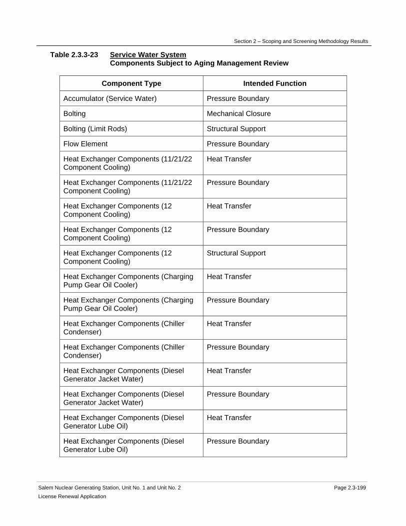
Section 2 – Scoping and Screening Methodology Results
Salem Nuclear Generating Station, Unit No. 1 and Unit No. 2 Page 2.3-199 License Renewal Application
Table 2.3.3-23 Service Water System Components Subject to Aging Management Review
Component Type Intended Function
Accumulator (Service Water) Pressure Boundary
Bolting Mechanical Closure
Bolting (Limit Rods) Structural Support
Flow Element Pressure Boundary
Heat Exchanger Components (11/21/22 Component Cooling)
Heat Transfer
Heat Exchanger Components (11/21/22 Component Cooling)
Pressure Boundary
Heat Exchanger Components (12 Component Cooling)
Heat Transfer
Heat Exchanger Components (12 Component Cooling)
Pressure Boundary
Heat Exchanger Components (12 Component Cooling)
Structural Support
Heat Exchanger Components (Charging Pump Gear Oil Cooler)
Heat Transfer
Heat Exchanger Components (Charging Pump Gear Oil Cooler)
Pressure Boundary
Heat Exchanger Components (Chiller Condenser)
Heat Transfer
Heat Exchanger Components (Chiller Condenser)
Pressure Boundary
Heat Exchanger Components (Diesel Generator Jacket Water)
Heat Transfer
Heat Exchanger Components (Diesel Generator Jacket Water)
Pressure Boundary
Heat Exchanger Components (Diesel Generator Lube Oil)
Heat Transfer
Heat Exchanger Components (Diesel Generator Lube Oil)
Pressure Boundary

Section 2 – Scoping and Screening Methodology Results
Salem Nuclear Generating Station, Unit No. 1 and Unit No. 2 Page 2.3-200 License Renewal Application
Component Type Intended Function
Heat Exchanger Components (ECCS Pump Room Coolers)
Heat Transfer
Heat Exchanger Components (ECCS Pump Room Coolers)
Pressure Boundary
Heat Exchanger Components (Fan Coil Unit Cooling Coils)
Heat Transfer
Heat Exchanger Components (Fan Coil Unit Cooling Coils)
Pressure Boundary
Heat Exchanger Components (Fan Coil Unit Motor Coolers)
Heat Transfer
Heat Exchanger Components (Fan Coil Unit Motor Coolers)
Pressure Boundary
Heat Exchanger Components (Safety Injection/Charging Pump Lube Oil Coolers)
Heat Transfer
Heat Exchanger Components (Safety Injection/Charging Pump Lube Oil Coolers)
Pressure Boundary
Heat Exchanger Components (Service Water Pump Motor Oil Coolers)
Heat Transfer
Heat Exchanger Components (Service Water Pump Motor Oil Coolers)
Pressure Boundary
Heat Exchanger Components (Station Air Compressor - Lube Oil)
Heat Transfer
Heat Exchanger Components (Station Air Compressor - Lube Oil)
Pressure Boundary
Heat Exchanger Components (Station Air Compressors-Intercoolers/Aftercooler)
Heat Transfer
Heat Exchanger Components (Station Air Compressors-Intercoolers/Aftercooler)
Pressure Boundary
Hoses Pressure Boundary
Piping and Fittings Leakage Boundary
Piping and Fittings Pressure Boundary
Piping and Fittings Structural Support
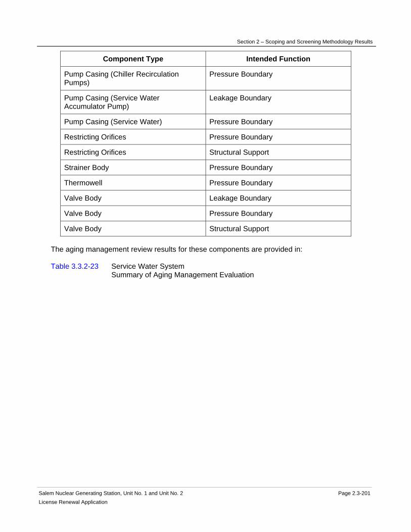
Section 2 – Scoping and Screening Methodology Results
Salem Nuclear Generating Station, Unit No. 1 and Unit No. 2 Page 2.3-201 License Renewal Application
Component Type Intended Function
Pump Casing (Chiller Recirculation Pumps)
Pressure Boundary
Pump Casing (Service Water Accumulator Pump)
Leakage Boundary
Pump Casing (Service Water) Pressure Boundary
Restricting Orifices Pressure Boundary
Restricting Orifices Structural Support
Strainer Body Pressure Boundary
Thermowell Pressure Boundary
Valve Body Leakage Boundary
Valve Body Pressure Boundary
Valve Body Structural Support The aging management review results for these components are provided in: Table 3.3.2-23 Service Water System Summary of Aging Management Evaluation

Section 2 – Scoping and Screening Methodology Results
Salem Nuclear Generating Station, Unit No. 1 and Unit No. 2 Page 2.3-202 License Renewal Application
2.3.3.24 Service Water Ventilation System
System Purpose The Service Water Ventilation System is a normally operating system designed to remove waste heat from the Service Water System components located in the Service Water Intake Structure. The Service Water Ventilation System is in scope for license renewal. The Service Water Intake Structure serves both Salem Unit 1 and 2. The Service Water Intake Structure consists of four service water intake compartments, each with its own control room. The Service Water Ventilation System for each compartment consists of an outside air intake penthouse, power-operated intake and exhaust dampers, and two exhaust fans discharging to the outdoors. The purpose of the Service Water Ventilation System is to remove waste heat from the Service Water System components located in the Service Water Intake Structure. The Service Water Ventilation System accomplishes this purpose by exhausting air from the Service Water Intake Structure service water intake compartments and control rooms. The two exhaust fans are physically separated and powered from separate sources. The exhaust fans and their controls and instrumentation are designed to Class I (seismic) criteria and can be powered from the standby AC power system. Each system is provided with its own controls, can be started manually or automatically, and can be tested independently to assure its availability. The air intake penthouse, supply and exhaust dampers are of non-seismic construction. Failure of the non-seismic ventilating equipment (dampers and intake penthouse) would not interfere with the ability of the exhaust fans to perform their intended function. The dampers fail open on loss of air or electric power. System Operation The Service Water Ventilation System for each compartment is comprised of an outside air intake penthouse, power-operated intake and exhaust dampers, and two exhaust fans discharging to the outdoors. The Service Water Ventilation System operates automatically in response to individual compartment or Service Water Intake Structure Control Room temperatures. On a small rise in compartment temperature, the smaller of two exhaust fans starts and discharges to the outdoors. Air-operated dampers that are controlled by room thermostats modulate supply air from the outdoors to provide the design compartment or control room temperature. On a greater rise in temperature, the larger fan starts, its intake damper opens and more air is induced to flow through the compartments. The exhaust fans stop and the supply and exhaust air dampers return by spring action to their closed positions when the system is shutdown. Prior to the ambient temperature in Service Water Intake Structure compartments or control rooms exceeding their maximum or minimum limits, the condition is alarmed in the Main Control Room.

Section 2 – Scoping and Screening Methodology Results
Salem Nuclear Generating Station, Unit No. 1 and Unit No. 2 Page 2.3-203 License Renewal Application
For more detailed information, see UFSAR Section 9.4.7. System Boundary The Service Water Ventilation System boundary begins at the Service Water Intake Structure outside air intake penthouse, which is mounted on the top of the Service Water Intake Structure and also at the outside air intake plenum for the Service Water Intake Structure Control Room. It continues through the intake air control damper, the Service Water Pump Room, the Service Water Intake Structure Control Room, the exhaust air shaft, the exhaust air damper, the exhaust fans and ends at the exhaust air plenum The Service Water Ventilation System airshafts are evaluated in the Service Water Intake Structure since they are formed by the Service Water Intake Structure walls. Not included in the Service Water Ventilation System license renewal boundary are the following interfacing systems, which are separately evaluated as license renewal systems: Control Air and Station Air System Service Water System Service Water Intake Structure Reason for Scope Determination The Service Water Ventilation System meets 10 CFR 54.4(a)(1) because it is a safety-related system that is relied upon to remain functional during and following design basis events. It meets 10 CFR 54.4(a)(2) because failure of nonsafety-related portions of the system could prevent satisfactory accomplishment of function(s) identified for 10 CFR 54.4(a)(1). It also meets 10 CFR 54.4(a)(3) because it is relied upon in the safety analyses or plant evaluations to perform a function that demonstrates compliance with the Commission's regulations for Fire Protection (10 CFR 50.48), and Station Blackout (10 CFR 50.63). The Service Water Ventilation System is not relied upon in any safety analyses or plant evaluations to perform a function that demonstrates compliance with the Commission's regulation for Environmental Qualification (10 CFR 50.49), Pressurized Thermal Shock (10 CFR 50.61), or Anticipated Transient Without Scram (10 CFR 50.62). System Intended Functions 1. Maintain emergency temperature limits within areas containing safety-related components. The Service Water Ventilation System removes heat from the Service Water System components located in the Service Water Intake Structure. 10 CFR 54.4(a)(1) 2. Resist nonsafety-related SSC failure that could prevent satisfactory accomplishment of a safety-related function. Failure of the non-seismic ventilating equipment (dampers and intake penthouse) would not interfere with the ability of the exhaust fans to perform their intended function. 10 CFR 54.4(a)(2) 3. Relied upon in safety analyses or plant evaluations to perform a function that demonstrates compliance with the Commission's regulations for Fire Protection (10 CFR 50.48). The Service Water Ventilation System supports the operation of the Service Water System during postulated fire events. 10 CFR 54.4(a)(3)

Section 2 – Scoping and Screening Methodology Results
Salem Nuclear Generating Station, Unit No. 1 and Unit No. 2 Page 2.3-204 License Renewal Application
4. Relied upon in safety analyses or plant evaluations to perform a function that demonstrates compliance with the Commission's regulations for Station Blackout (10 CFR 50.63). The Service Water Ventilation System supports the operation of the Service Water System during restoration from a Station Blackout event. 10 CFR 54.4(a)(3) UFSAR References 3.2.1.2 9.4.7 License Renewal Boundary Drawings Unit 1: None Unit 2: None Unit Common: None

Section 2 – Scoping and Screening Methodology Results
Salem Nuclear Generating Station, Unit No. 1 and Unit No. 2 Page 2.3-205 License Renewal Application
Table 2.3.3-24 Service Water Ventilation System Components Subject to Aging Management Review
Component Type Intended Function
Bolting Mechanical Closure
Damper Housing Pressure Boundary
Ducting and Components Pressure Boundary
Fan Housing Pressure Boundary The aging management review results for these components are provided in: Table 3.3.2-24 Service Water Ventilation System Summary of Aging Management Evaluation
Section 2 – Scoping and Screening Methodology Results
Salem Nuclear Generating Station, Unit No. 1 and Unit No. 2 Page 2.3-206 License Renewal Application
2.3.3.25 Spent Fuel Cooling System
System Purpose The Spent Fuel Cooling (SFC) System is a normally operating mechanical system designed to remove from the Spent Fuel Pool the heat generated by stored spent fuel elements. The Spent Fuel Cooling System serves the Spent Fuel Pool located in the Fuel Handling Building adjacent to the Containment Building. The Spent Fuel Cooling System is capable of maintaining Spent Fuel Pool temperatures within design limits. The Spent Fuel Cooling System consists of the following three loops: the pool cooling loop, the purification loop and the skimmer loop. The Spent Fuel Cooling System is in scope for license renewal. The function of the pool cooling loop is to remove heat from the spent fuel. The function of the purification loop is to purify water from the Spent Fuel Pool, transfer pool and Refueling Water Storage Tank (RWST). The function of the skimmer loop is to maintain clarity of the Spent Fuel Pool water by removing particles floating on the surface of the pool water. The purpose of the pool cooling loop of the Spent Fuel Cooling System is to remove decay heat from the spent fuel stored in the Spent Fuel Pool. The Spent Fuel Cooling System accomplishes this purpose by forced circulation of Spent Fuel Pool water through a heat exchanger and back to the Spent Fuel Pool. The purpose of the purification loop of the Spent Fuel Cooling System is to purify Spent Fuel Pool water. The purification loop accomplishes this purpose by drawing water from the spent fuel pool, pumping the water through a demineralizer and filter, and returning the water to the spent fuel pool. The purification loop can also be aligned to purify water from the transfer pool or the RWST by circulating water from either source through the same demineralizer and filter. The purification loop contains normally closed containment boundary isolation valves. The purpose of the skimmer loop of the Spent Fuel Cooling System is to clarify Spent Fuel Pool water by removing particles floating on the surface of the water. The skimmer loop accomplishes this purpose by pumping Spent Fuel Pool water from surface skimmers through a strainer and filter and returning the water to the spent fuel pool. Spent Fuel Cooling System operation is initiated by manual control for all functions. System Operation The Spent Fuel Cooling (SFC) System is comprised of two Spent Fuel Pumps, one Refueling Water Purification Pump, one Spent Fuel Pool Skimmer Pump, one Spent Fuel Pool Heat Exchanger, one Spent Fuel Pool Demineralizer, one Spent Fuel Pool Filter, One Spent Fuel Pool Skimmer Filter, one Refueling Water Purification Filter, one Spent Fuel Pool Strainer and one Spent Fuel Pool Skimmer Strainer. It also includes associated piping, valves, and instrumentation. Spent Fuel Cooling System operation is manually initiated for all functions. For the Spent Fuel Cooling System cooling loop, water flows from the Spent Fuel Pool through the Spent Fuel Pool Strainer to the suction of one of the Spent Fuel Pumps. The discharge

Section 2 – Scoping and Screening Methodology Results
Salem Nuclear Generating Station, Unit No. 1 and Unit No. 2 Page 2.3-207 License Renewal Application
from the Spent Fuel pump flows through the tube side of the Spent Fuel Pool Heat Exchanger, and the cooled water returns to the Spent Fuel Pool. Two Spent Fuel Pumps provide redundant pumping capacity. Heat exchanger redundancy is provided by the capability to cross connect to the other unit's Spent Fuel Pool Heat Exchanger. The Spent Fuel Pumps are powered from 460 volt vital busses. A portion of the flow through the Spent Fuel Pumps may be diverted away from the Spent Fuel Pool Heat Exchanger and instead routed to the Spent Fuel Pool Demineralizer and Spent Fuel Pool Filter to maintain pool water clarity and purity. After passing through the Spent Fuel Pool Demineralizer and Spent Fuel Pool filter, the diverted flow returns to the Spent Fuel Pool. The Spent Fuel Cooling System skimmer loop maintains water clarity by filtering particulates floating on the surface of the Spent Fuel Pool. The skimmer loop draws water from the surface of the Spent Fuel Pool through the two Spent Fuel Pool Skimmers. The flow passes through the Spent Fuel Pool Skimmer Strainer to the suction of the Spent Fuel Pool Skimmer Pump. The water is pumped through the Spent Fuel Pool Skimmer Filter and returned to the Spent Fuel Pool at three locations remote from the skimmers. The Spent Fuel Pool Demineralizer and Spent Fuel Pool Filter may also be used to purify water from the Refueling Canal. Circulation of Refueling Canal water is normally accomplished with the Spent Fuel Pool cooling loop, as described above, because the gate between the Refueling Canal and the Spent Fuel Pool is normally removed. If the gate is installed, then the system can be aligned for the Refueling Water Purification Pump to take suction directly from the refueling canal. It is pumped through the Spent Fuel Pool Demineralizer and the Refueling Water Purification Filter and returned to the Refueling Canal. The Spent Fuel Pool Demineralizer and Spent Fuel Pool Filter may also be used to purify water from the RWST. The system can be aligned for the Refueling Water Purification Pump to take suction from the RWST. It is pumped through the Spent Fuel Pool Demineralizer and the Refueling Water Purification Filter and returned to the Refueling Canal. The Spent Fuel Cooling System also maintains containment integrity by closure of the valves connecting the purification loop to the Refueling Canal, and maintains the pressure boundary of the Refueling Water Storage Tank by closure of the valves connecting the purification loop with the Refueling Water Storage Tank. These valves are normally closed. For more detailed information, see UFSAR Section 9.1.3. System Boundary The boundary of the Spent Fuel Cooling (SFC) System cooling loop begins at the Spent Fuel Pool Strainer. It continues through the Spent Fuel Pump, through the Spent Fuel Pool Heat Exchanger, and returns to the Spent Fuel Pool. Also included in the boundary is the piping that cross connects the Spent Fuel Cooling System with the alternate unit's Spent Fuel Pool Heat Exchanger. The boundary of the Spent Fuel Cooling System purification loop begins at the Spent Fuel Pump discharge line and continues through the Spent Fuel Pool Demineralizer to the Spent Fuel Pool Filter to the return line to the Spent Fuel Pool. Also included in the boundary is the line from the Refueling Water Storage Tank beginning at the outlet of the Refueling Water
Section 2 – Scoping and Screening Methodology Results
Salem Nuclear Generating Station, Unit No. 1 and Unit No. 2 Page 2.3-208 License Renewal Application
Purification Stop Valve and continuing through the Refueling Water Purification Pump to the Spent Fuel Pool Demineralizer to the Refueling Water Purification Filter and terminating downstream of the Refueling Water Purification Filter, at the connection with the return line to the Refueling Water Storage Tank. Also included is the line from the Refueling Canal beginning downstream of the Refueling Canal outlet isolation valve, and continuing to the Refueling Water Purification Pump, through the Spent Fuel Pool Demineralizer and Refueling Water Purification Filter and continuing through the return line terminating at the Refueling Canal inlet isolation valve. The boundary of the Spent Fuel Cooling System skimmer loop begins at the Spent Fuel Pool Skimmers and continues through the Spent Fuel Pool Skimmer Strainer, Spent Fuel Pool Skimmer Pump and Spent Fuel Pool Skimmer Filter, terminating at the discharge of the return line to the Spent Fuel Pool. All associated piping, components and instrumentation contained within the flow paths described above are included in the system evaluation boundary. Also included in the license renewal scoping boundary of the Spent Fuel Cooling System are those water filled portions of nonsafety-related piping and equipment located in proximity to equipment performing a safety-related function. This includes the nonsafety-related portions of the system located within the Auxiliary Building and the Fuel Handling Building. For more information, refer to the license renewal boundary drawing for identification of this boundary, shown in red. Not included in the Spent Fuel Cooling System license renewal scoping boundary are the Spent Fuel Pool and the Refueling Canal, which are separately evaluated with the Fuel Handling Building Structure and Containment Structure, respectively. The Spent Fuel Pool Heat Exchanger is evaluated for aging management with the Component Cooling System. Not included in the Spent Fuel Cooling System license renewal scoping boundary are the following interfacing systems, which are separately evaluated as license renewal systems: Component Cooling System Containment Structure Demineralized Water System Fuel Handling Building Radwaste System Safety Injection System Reason for Scope Determination The Spent Fuel Cooling System meets the scoping requirements of 10 CFR 54.4(a)(1) because it is a safety-related system which is relied upon to remain functional during and following design basis events. It meets the scoping requirements of 10 CFR 54.4(a)(2) because failure of nonsafety-related portions of the system could prevent satisfactory accomplishment of function(s) identified for 10 CFR 54.4(a)(1). The Spent Fuel Cooling System is not relied upon in any safety analyses or plant evaluations to perform a function that demonstrates compliance with the Commission's regulation for Fire Protection (10 CFR 50.48), Environmental Qualification (10 CFR 50.49), Pressurized Thermal Shock (10 CFR 50.61), Anticipated Transient Without Scram (10 CFR 50.62) or Station Blackout (10 CFR 50.63).

Section 2 – Scoping and Screening Methodology Results
Salem Nuclear Generating Station, Unit No. 1 and Unit No. 2 Page 2.3-209 License Renewal Application
System Intended Functions 1. Provide primary containment boundary. The Refueling Water Purification Pump supply and discharge lines to and from the Refueling Canal penetrate containment. The containment isolation valves are required to maintain containment integrity. 10 CFR 54.4(a)(1) 2. Ensure adequate cooling in the Spent Fuel Pool to maintain stored fuel within acceptable temperature limits. The Spent Fuel Cooling System is designed to remove from the Spent Fuel Pool the heat generated by stored spent fuel elements and maintain the fuel within design limits. 10 CFR 54.4(a)(1) 3. Resist nonsafety-related SSC failure that could prevent satisfactory accomplishment of a safety-related function. The Spent Fuel Cooling system includes nonsafety-related water filled lines in the Fuel Handling Building and Auxiliary Building that have the potential for spatial interactions (spray or leakage) with safety-related SSCs. 10 CFR 54.4(a)(2) UFSAR References 9.1.3 15.4.6 License Renewal Boundary Drawings Unit 1: LR-205233 Sheet 1 LR-205234 Sheet 1 LR-205239 Sheet 3 Unit 2: LR-205333 Sheet 1 LR-205334 Sheet 1 LR-205339 Sheet 3 Unit Common: None

Section 2 – Scoping and Screening Methodology Results
Salem Nuclear Generating Station, Unit No. 1 and Unit No. 2 Page 2.3-210 License Renewal Application
Table 2.3.3-25 Spent Fuel Cooling System Components Subject to Aging Management Review
Component Type Intended Function
Bolting Mechanical Closure
Filter Housing Leakage Boundary
Flow Element Leakage Boundary
Heat Exchanger Components (Spent Fuel)
Evaluated with the Component Cooling System
Piping and Fittings Leakage Boundary
Piping and Fittings Pressure Boundary
Pump Casing (Purification Pump) Leakage Boundary
Pump Casing (Skimmer Pump) Leakage Boundary
Pump Casing (Spent Fuel Cooling Pump) Pressure Boundary
Strainer Body Leakage Boundary
Tanks (Demineralizer) Leakage Boundary
Thermowell Pressure Boundary
Valve Body Leakage Boundary
Valve Body Pressure Boundary The aging management review results for these components are provided in: Table 3.3.2-25 Spent Fuel Cooling System Summary of Aging Management Evaluation

Section 2 – Scoping and Screening Methodology Results
Salem Nuclear Generating Station, Unit No. 1 and Unit No. 2 Page 2.3-211 License Renewal Application
2.3.3.26 Switchgear and Penetration Area Ventilation System
System Purpose The Switchgear and Penetration Area Ventilation System is a safety-related mechanical, normally operating system designed to maintain acceptable levels of temperature and cleanliness in the switchgear rooms, electrical penetration area, and the ventilation equipment room (chiller room). The purpose of the Switchgear and Penetration Area Ventilation System is to maintain acceptable levels of temperature and cleanliness in the switchgear rooms, electrical penetration area, and the ventilation equipment room (chiller room). This is achieved through two supply fans; one switchgear room exhaust fan and one electrical penetration exhaust fan to maintain area temperatures under all conditions. The Switchgear and Penetration Area Ventilation System also provides a slightly positive pressure and isolation capabilities for fire conditions in the switchgear rooms and electrical penetration areas. The Switchgear and Penetration Area Ventilation System is in scope for license renewal. System Operation The Switchgear and Penetration Areas Ventilation System for each unit consists of one 100-percent capacity supply-air filtering unit, three 50-percent capacity fans to supply filtered air through supply ducts to the various areas, and two 100-percent capacity return/exhaust air fans to either exhaust air out of the switchgear rooms or return air for recirculation. The system also includes two exhaust fans for the electrical penetration area. Normally, two of the three supply fans operate with the third fan as a standby. One of the switchgear return/exhaust fans operates with the second fan in standby. Both of the electrical penetration area exhaust fans operate. Supply temperature is monitored and outside air intake dampers, recirculation damper, and exhaust damper modulates to provide relatively constant supply air temperature to all areas of this system. When the supply air temperature is equal to or above 75 F, the system automatically aligns to supply 100-percent outside air; that is, the recirculation damper closed and the intake and exhaust dampers fully opened. When the supply air temperature is between 65 F and 75 F, the intake dampers, the recirculation damper, and the exhaust damper modulate to temper the supply as required to maintain temperature. When the supply air temperature is equal to or less than 65 F, both electrical penetration area exhaust fans stop. The two supply fans and the switchgear return/exhaust fan continue to operate at full flow. In this situation, the recirculation damper is fully open and the outside air intake dampers are fully closed. For more detailed information, see UFSAR Section 9.4.6. System Boundary The Switchgear and Penetration Area Ventilation System consists of supply air filter enclosure, supply fans, return/exhaust fans, control dampers, and ductwork with associated components. Most of the equipment is located in the ventilation equipment room (chiller room). The Switchgear and Penetration Area Ventilation System boundary begins at the penthouse

Section 2 – Scoping and Screening Methodology Results
Salem Nuclear Generating Station, Unit No. 1 and Unit No. 2 Page 2.3-212License Renewal Application
intake louver and plenum and continues through the filter enclosure by the supply fans and discharges into a common air duct which continues to the switchgear rooms, electrical penetration area, and ventilation equipment room (chiller room) where the supply portion of the system ends. The Switchgear and Penetration Area Ventilation System boundary includes return/exhaust airflow from the switchgear rooms through the switchgear room ventilation exhaust dampers and the CO2 shutoff dampers into two air ducts, which continues to the switchgear room return/exhaust fans via a common plenum. The boundary continues through a common exhaust plenum and into ductwork that discharges to atmosphere via the exhaust penthouse where the boundary ends. The boundary also includes an alternate recirculation flow path back to the inlet filter enclosure. The Switchgear and Penetration Area Ventilation System boundary also includes airflow from the electrical penetration area and from the ventilation equipment room (chiller room) through exhaust fans and discharged to atmosphere via the exhaust penthouse where the boundary ends. All associated piping, components and instrumentation contained within the flow path described above are included in the system evaluation boundary. There are no interfacing systems that are evaluated separately. Reason for Scope Determination The Switchgear and Penetration Area Ventilation System meets 10 CFR 54.4(a)(1) because it is a safety-related system that is relied upon to remain functional during and following design basis events. The Switchgear and Penetration Area Ventilation System is not in scope under 10 CFR 54.4(a)(2) because failure of nonsafety-related portions of the system would not prevent satisfactory accomplishment of function(s) identified for 10CFR54.4(a)(1). The Switchgear and Penetration Area Ventilation System meets 10 CFR 54.4(a)(3) because it is relied upon in the safety analyses or plant evaluations to perform a function that demonstrates compliance with the Commission's regulations for Fire Protection (10 CFR 50.48) and Station Blackout (10 CFR 50.63). The Switchgear and Penetration Area Ventilation System is not relied upon in any safety analyses or plant evaluations to perform a function that demonstrates compliance with the Commission's regulation for Environmental Qualification (10 CFR 50.49), Pressurized Thermal Shock (10 CFR 50.61), or Anticipated Transient Without Scram (10 CFR 50.62). System Intended Functions 1. Maintain emergency temperature limits within areas containing safety-related components. Provide acceptable levels of temperature and cleanliness in the areas served to support operability under normal and accident conditions. 10 CFR 54.4(a)(1) 2. Relied upon in safety analyses or plant evaluations to perform a function that demonstrates compliance with the Commission's regulations for Fire Protection (10 CFR 50.48). The system provides isolation capabilities for fire conditions in the switchgear rooms and electrical penetration areas. 10 CFR 54.4(a)(3)

Section 2 – Scoping and Screening Methodology Results
Salem Nuclear Generating Station, Unit No. 1 and Unit No. 2 Page 2.3-213 License Renewal Application
3. Relied upon in safety analyses to perform a function that demonstrates compliance with the Commission's regulations for Station Blackout (10 CFR 50.63). Maintain temperature within NUMARC limits for the SBO coping duration. 10 CFR 54.4(a)(3) UFSAR References 9.4.6 FIG 9.4-6a FIG 9.4-6b License Renewal Boundary Drawings Unit 1: LR-205248 Sheet 1 Unit 2: LR-205348 Sheet 1 Unit Common: None
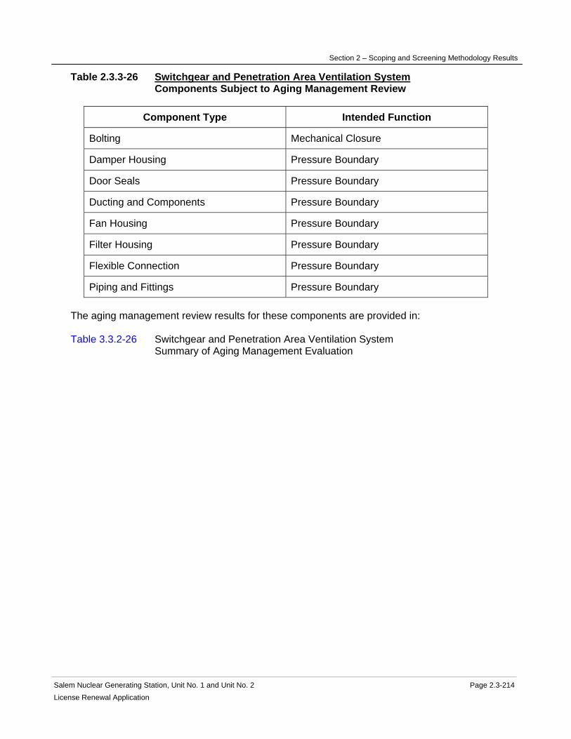
Section 2 – Scoping and Screening Methodology Results
Salem Nuclear Generating Station, Unit No. 1 and Unit No. 2 Page 2.3-214 License Renewal Application
Table 2.3.3-26 Switchgear and Penetration Area Ventilation System Components Subject to Aging Management Review
Component Type Intended Function
Bolting Mechanical Closure
Damper Housing Pressure Boundary
Door Seals Pressure Boundary
Ducting and Components Pressure Boundary
Fan Housing Pressure Boundary
Filter Housing Pressure Boundary
Flexible Connection Pressure Boundary
Piping and Fittings Pressure Boundary The aging management review results for these components are provided in: Table 3.3.2-26 Switchgear and Penetration Area Ventilation System Summary of Aging Management Evaluation

Section 2 – Scoping and Screening Methodology Results
Salem Nuclear Generating Station, Unit No. 1 and Unit No. 2 Page 2.3-215 License Renewal Application
2.3.4 STEAM AND POWER CONVERSION SYSTEM
The following systems are addressed in this section:
• Auxiliary Feedwater System (2.3.4.1)
• Main Condensate and Feedwater System (2.3.4.2)
• Main Condenser and Air Removal System (2.3.4.3)
• Main Steam System (2.3.4.4)
• Main Turbine and Auxiliaries System (2.3.4.5)

Section 2 – Scoping and Screening Methodology Results
Salem Nuclear Generating Station, Unit No. 1 and Unit No. 2 Page 2.3-216 License Renewal Application
2.3.4.1 Auxiliary Feedwater System
System Purpose The Auxiliary Feedwater System is a standby, steam and power conversion mechanical system designed to provide feedwater to the steam generators for heat removal from the Reactor Coolant System under normal and accident conditions. These accident conditions include the loss of normal feedwater, steam generator tube rupture, main steam or feedwater line break, and small break LOCA. During normal power operation, the Auxiliary Feedwater System is a standby system, and is used during plant startup and shutdown when the main feedwater system is not available. The Auxiliary Feedwater System is in scope for license renewal. The Auxiliary Feedwater System accomplishes this purpose by providing cooling water flow to the secondary side of the steam generators during normal and accident conditions. Each unit is equipped with one turbine-driven and two motor-driven auxiliary feedwater pumps. The motor-driven auxiliary feedwater pumps are started automatically on the following signals: (1) loss of both main feedwater pumps, (2) low-low water level on any steam generator, (3) ATWS Mitigation System Actuation Circuitry (AMSAC) actuation, and (4) any emergency core cooling system (ECCS) actuation signal (blackout or accident). The turbine-driven auxiliary feedwater pump is started on the following signals: (1) low-low level in any two steam generators, (2) AMSAC actuation, (3) loss of control air, (4) loss of 125vDC control power, and (5) group bus undervoltage. The motor-driven auxiliary feedwater pumps are automatically sequenced onto the diesel generators following an ECCS actuation (loss of offsite power). For other design basis events, the auxiliary feedwater pumps are started based on the actuation signals listed above and loaded onto the diesel generators (if required). The auxiliary feedwater tank has sufficient capacity to hold the plant at hot zero power for two hours following a reactor trip from full equilibrium power, followed by a six-hour shutdown to hot shutdown conditions for Residual Heat Removal System operation. Chemicals (hydrazine) are added at the discharge of the auxiliary feedwater pumps to maintain steam generator chemistry during shutdown and startup conditions. During tornado warning conditions, a low-low level suction trip on the auxiliary feedwater storage tank is armed, and will trip the auxiliary feedwater pumps if the tank is damaged during this event. The demineralized water storage tanks, fire protection tanks, and the service water system provide alternate sources of water; however the fire protection tanks and the service water system must be connected to the Auxiliary Feedwater System through spool pieces installed by the operators. Unit 1 and Unit 2 alternate suction headers are cross-tied through normally-closed manual isolation valves. The Demineralized Water System and Unit 1 Service Water System are on the Unit 1 alternate suction header, and the Fire Protection System and the Unit 2 Service Water System are on the Unit 2 alternate suction header. System Operation The Auxiliary Feedwater System is comprised of three pumps (two motor-driven pumps and one turbine-driven pump), one storage tank, and the necessary piping, valves, and

Section 2 – Scoping and Screening Methodology Results
Salem Nuclear Generating Station, Unit No. 1 and Unit No. 2 Page 2.3-217 License Renewal Application
instrumentation designed to provide two redundant cooling loops. The loops are designed such that each motor-driven pump is capable of discharging through a flow nozzle into two lines directing flow into two steam generators. The turbine-driven pump provides flow to all four steam generators. The motor-driven auxiliary feedwater pumps are started on the following signals: (1) loss of both main feedwater pumps, (2) low-low water level on any steam generator, (3) AMSAC actuation, and (4) any ECCS actuation signal (blackout or accident). The turbine-driven auxiliary feedwater pump is started on the following signals: (1) low-low level in any two steam generators, (2) AMSAC actuation, (3) loss of control air, (4) loss of 125vDC control power, and (5) group bus undervoltage. The auxiliary feedwater pumps normally take water from the auxiliary feedwater storage tank and provide flow to all four steam generators when the unit is shutdown. During emergency operations, the auxiliary feedwater pumps use the same flowpath to remove decay heat from the Reactor Coolant System through the steam generators. A single pump is capable of removing the decay heat load for all design basis accidents. The demineralized water storage tanks, fire protection tanks, and the service water system provide alternate sources of water; however the fire protection tanks and the service water system must be connected to the Auxiliary Feedwater System through spool pieces installed by the operators. Most of the piping from the alternate water sources (demineralized water and fire protection) is shown on the Unit 1 drawings and the demineralized water piping is located in the Unit 1 switchgear room, while the fire protection piping is located in the Unit 2 switchgear room. The Service Water System piping for the alternate water source is located in its respective unit. For more detailed information, see UFSAR Section 10.4.7.2. System Boundary The Auxiliary Feedwater System boundary begins at the auxiliary feedwater storage tank and continues through the auxiliary feedwater pumps to the four safety-related loops. These four piping loops continue from the Auxiliary Building to the Inner and Outer Penetration Areas, and end at the downstream side of the stop valves where the Auxiliary Feedwater System connects into the main feedwater piping. The boundary also includes the piping on the discharge of the pumps and the recirculation lines back to the auxiliary feedwater storage tank. The boundary includes piping on the suction side of the pumps from the alternate water sources (demineralized water, fire protection, and service water), which are evaluated in their own license renewal systems. For the interface with the Demineralized Water System, the boundary for the Auxiliary Feedwater System starts at the check valve prior to entry into the Auxiliary Building. Similarly, for the interface with the Fire Protection System, the boundary starts at the check valve entering the Auxiliary Building from the Service Building. The boundary with the Service Water System starts at the spool piece to the Auxiliary Feedwater System. Also included in the boundary is the main steam piping that supplies steam to the turbine-driven auxiliary feedwater pump that starts at the manual isolation valves from only the 11/13 (21/23) main steam loops and continues through the steam turbine. The steam turbine on the auxiliary feedwater pump and the associated piping is included in the scope of the Auxiliary Feedwater System.
Section 2 – Scoping and Screening Methodology Results
Salem Nuclear Generating Station, Unit No. 1 and Unit No. 2 Page 2.3-218 License Renewal Application
The boundary also includes the nonsafety-related chemical treatment lines from the Auxiliary Building wall to the discharge of the auxiliary feedwater pumps. All associated piping, components and instrumentation contained within the flow path described above are included in the system evaluation boundary. Also included in the Auxiliary Feedwater System license renewal scoping boundary are those portions of nonsafety-related piping and equipment that extend beyond the safety-related/nonsafety-related interface up to the location of the first seismic anchor, or to a point no longer in proximity to equipment performing a safety-related function, whichever extends furthest. Included in this boundary are pressure-retaining components relied upon to preserve the leakage boundary intended function of this portion of the system. For more information, refer to the license renewal boundary drawing for identification of this boundary, shown in red. Not included in the Auxiliary Feedwater System license renewal scoping boundary are the following interfacing systems, which are separately evaluated as license renewal systems: Auxiliary Building Ventilation System Condensate and Feedwater Auxiliaries System Demineralized Water System Fire Protection System Main Condensate and Feedwater System Main Steam System Non-radioactive Drain System Radwaste System Steam Generators Service Water System Reason for Scope Determination The Auxiliary Feedwater System meets 10 CFR 54.4(a)(1) because it is a safety-related system that is relied upon to remain functional during and following design basis events. It meets 10 CFR 54.4(a)(2) because failure of nonsafety-related portions of the system could prevent satisfactory accomplishment of function(s) identified for 10 CFR 54.4(a)(1). It also meets 10 CFR 54.4(a)(3) because it is relied upon in the safety analyses or plant evaluations to perform a function that demonstrates compliance with the Commission's regulations for Fire Protection (10 CFR 50.48), Environmental Qualification (10 CFR 50.49), Anticipated Transient Without Scram (10 CFR 50.62), and Station Blackout (10 CFR 50.63). The Auxiliary Feedwater System is not relied upon in any safety analyses or plant evaluations to perform a function that demonstrates compliance with the Commission's regulation for Pressurized Thermal Shock (10 CFR 50.61). System Intended Functions 1. Remove residual heat from the reactor coolant system. The Auxiliary Feedwater System provides heat removal from the Reactor Coolant System through the Steam Generators during normal and accident conditions. 10 CFR 54.4(a)(1) 2. Provide primary containment boundary. The Auxiliary Feedwater System contains valves that provide the containment isolation function to confine radioactive materials. 10 CFR

Section 2 – Scoping and Screening Methodology Results
Salem Nuclear Generating Station, Unit No. 1 and Unit No. 2 Page 2.3-219 License Renewal Application
54.4(a)(1) 3. Provide secondary heat sink. The Auxiliary Feedwater System provides heat removal from the Reactor Coolant System through the Steam Generators during normal and accident conditions. 10 CFR 54.4(a)(1) 4. Resist nonsafety-related SSC failure that could prevent satisfactory accomplishment of a safety-related function. The Auxiliary Feedwater System contains nonsafety-related water filled lines, which have the potential for spatial interactions (spray or leakage) with safety-related equipment. 10 CFR 54.4(a)(2) 5. Relied upon in safety analyses or plant evaluations to perform a function that demonstrates compliance with the Commission's regulations for Fire Protection (10 CFR 50.48). The Auxiliary Feedwater System is credited for fire protection by providing controls and indication for reactor shutdown outside the control room. 10 CFR 54.4(a)(3) 6. Relied upon in safety analyses or plant evaluations to perform a function that demonstrates compliance with the Commission's regulations for Environmental Qualification (10 CFR 50.49). The Auxiliary Feedwater System contains controls and instrumentation that are credited for Equipment Qualification. 10 CFR 54.4(a)(3) 7. Relied upon in safety analyses or plant evaluations to perform a function that demonstrates compliance with the Commission's regulations for Anticipated Transients without Scram (10 CFR 50.62). The Auxiliary Feedwater System receives actuation signals from the AMSAC to start the auxiliary feedwater pumps, if the reactor trip breakers fail to open. 10 CFR 54.4(a)(3) 8. Relied upon in safety analyses or plant evaluations to perform a function that demonstrates compliance with the Commission's regulations for Station Blackout (10 CFR 50.63). The Auxiliary Feedwater System provides water from a stored source for secondary heat removal. 10 CFR 54.4(a)(3) UFSAR References 10.4.7.2 License Renewal Boundary Drawings Unit 1: LR-205203 Sheet 1 LR-205236 Sheet 1 LR-205246 Sheet 1 LR-205246 Sheet 2 Unit 2: LR-205303 Sheet 1 LR-205336 Sheet 1 Unit Common: LR-205214 Sheet 1

Section 2 – Scoping and Screening Methodology Results
Salem Nuclear Generating Station, Unit No. 1 and Unit No. 2 Page 2.3-220License Renewal Application
Table 2.3.4-1 Auxiliary Feedwater System Components Subject to Aging Management Review
Component Type Intended Function
Bird Screen Filter
Bolting Mechanical Closure
Flow Element Pressure Boundary
Heat Exchanger Components (Auxiliary Feedwater Storage Tank)
Leakage Boundary
Heat Exchanger Components (Auxiliary Feedwater Storage Tank)
Pressure Boundary
Heat Exchanger Components (Turbine-Driven Pump Governor, Turbine Bearing)
Heat Transfer
Heat Exchanger Components (Turbine-Driven Pump Governor, Turbine Bearing)
Pressure Boundary
Piping and Fittings Leakage Boundary
Piping and Fittings Pressure Boundary
Pump Casing (AFST Circulator) Pressure Boundary
Pump Casing (Auxiliary Feedwater) Pressure Boundary
Restricting Orifices Leakage Boundary
Restricting Orifices Pressure Boundary
Restricting Orifices Throttle
Strainer Body Pressure Boundary
Tanks (Auxiliary Feedwater Storage Tank)
Pressure Boundary
Thermowell Pressure Boundary
Turbine Casing (Turbine-driven Auxiliary Feedwater)
Pressure Boundary
Valve Body Leakage Boundary
Valve Body Pressure Boundary

Section 2 – Scoping and Screening Methodology Results
Salem Nuclear Generating Station, Unit No. 1 and Unit No. 2 Page 2.3-221 License Renewal Application
The aging management review results for these components are provided in: Table 3.4.2-1 Auxiliary Feedwater System Summary of Aging Management Evaluation

Section 2 – Scoping and Screening Methodology Results
Salem Nuclear Generating Station, Unit No. 1 and Unit No. 2 Page 2.3-222 License Renewal Application
2.3.4.2 Main Condensate and Feedwater System
System Purpose The Main Condensate and Feedwater System is a normally operating mechanical system designed to maintain water level in the steam generators throughout all modes of normal plant operation. The Main Condensate and Feedwater System is in scope for license renewal. However, portions of the Main Condensate and Feedwater System are not required to perform intended functions and are not in scope. The Main Condensate and Feedwater System has several interfaces with other systems that are not in the license renewal boundary of the Main Condensate and Feedwater System. The purpose of the Main Condensate and Feedwater System is to maintain steam generator water level during all modes of normal plant operation. The Main Condensate and Feedwater System accomplishes this by heating deaerated condensate from the main condenser and delivering it to the steam generators. The Main Condensate and Feedwater System delivers the water to the steam generators to match the steam demand for the turbine load. The Main Condensate and Feedwater System isolation and regulating valves automatically close to stop flow to the steam generators on high-high level or a safety injection signal. The feedwater line to each steam generator is also provided with a check valve that serves as the containment isolation valve. System Operation The Main Condensate and Feedwater System is comprised of three condensate pumps, three parallel strings of low pressure feedwater heaters (five heaters per string), two feedwater pumps, three parallel strings of high pressure feedwater heaters (one heater per string) and the required piping, valves, instrumentation, and controls. For normal operation at full load conditions, the Main Condensate and Feedwater System uses three condensate pumps, three low pressure feedwater heater strings, two feedwater pumps, and three high pressure feedwater heater strings. The condensate pumps take suction from the main condenser and pump water through the low pressure feedwater heaters to the feedwater pump suction header. The feedwater pumps discharge through the high pressure feedwater heaters to a common header that supplies each of the four steam generators through the respective feedwater flow control and containment isolation valves. The flow control valves modulate to control steam generator level. The flow control and isolation valves close automatically under the appropriate accident/transient conditions. The Main Condensate and Feedwater System has recirculation and bypass lines necessary to provide the following functions; condensate and feedwater pump protection during low flow conditions, system clean up following outages, and heater string removal during operation for maintenance. The pumps and valves are manipulated for normal operation by the control room operator and field operators. For more detailed information, see UFSAR Section 10.4.

Section 2 – Scoping and Screening Methodology Results
Salem Nuclear Generating Station, Unit No. 1 and Unit No. 2 Page 2.3-223 License Renewal Application
System Boundary The Main Condensate and Feedwater System begins at the main condenser hotwell outlet piping, continues to a common condensate pump suction header, through the condensate pumps to a common discharge header. The boundary continues through the common discharge header into branch connections that supply the low pressure feedwater heater strings, condensate polishing, and steam generator blowdown cooling. Condensate polishing and gland sealing are evaluated with the Condensate and Feedwater Auxiliaries System. The steam generator blowdown cooling is evaluated with Steam Generators. The boundary continues from the common condensate pump discharge header to the five low pressure feedwater heaters in each of the low pressure feedwater heater strings, to the main feedwater pump common suction header, to the main feedwater pumps to a common discharge header, continues into each of the high pressure feedwater heaters and combines into a common feedwater header. The boundary continues through the common feedwater header to a branch connection that supplies the flow measuring devices, flow control valves, and isolation valves and continues into the Containment Structure where the boundary terminates at the interface with the Steam Generators. All associated piping, components, and instrumentation contained within the flow path described above are included in the system evaluation boundary. Also included is branch connection piping for interfacing systems out to and including the first manual, automatic, or check valve capable of providing an isolation function should an interfacing system malfunction impact the Main Condensate and Feedwater System's ability to perform its 10 CFR 50.48 intended function. The feedwater heater tubes and tube side components are in scope for pressure boundary function only. Shell side components are not required for heat transfer or leakage boundary functions and are not in scope. Not included in the Main Condensate and Feedwater System license renewal scoping boundary are the feedwater heater drain pumps, feedwater pump turbine and feedwater pump turbine lube oil system as these components are part of the Condensate and Feedwater Auxiliaries System, which is not in scope for license renewal. Not included in the Main Condensate and Feedwater System license renewal scoping boundary are the following interfacing systems, which are separately evaluated as license renewal systems: Compressed Air System Condensate and Feedwater Auxiliaries System Main Condenser and Air Removal System Main Turbine and Auxiliaries System Sampling System Steam Generators Reason for Scope Determination The Main Condensate and Feedwater System meets 10 CFR 54.4(a)(1) because it is a safety-related system that is relied upon to remain functional during and following design basis events. It meets 10 CFR 54.4(a)(2) because failure of nonsafety-related portions of the system could prevent satisfactory accomplishment of function(s) identified for 10 CFR

Section 2 – Scoping and Screening Methodology Results
Salem Nuclear Generating Station, Unit No. 1 and Unit No. 2 Page 2.3-224 License Renewal Application
54.4(a)(1). It also meets 10 CFR 54.4(a)(3) because it is relied upon in the safety analyses or plant evaluations to perform a function that demonstrates compliance with the Commission's regulations for Fire Protection (10 CFR 50.48), Environmental Qualification (10 CFR 50.49), and Station Blackout (10 CFR 50.63). The Main Condensate and Feedwater System is not relied upon in any safety analyses or plant evaluations to perform a function that demonstrates compliance with the Commission's regulation for Pressurized Thermal Shock (10 CFR 50.61) or Anticipated Transient Without Scram (10 CFR 50.62). System Intended Functions 1. Provide primary containment boundary. The Main Condensate and Feedwater System includes feedwater isolation valves and piping up to the steam generators to assure that radioactive material is not inadvertently transferred out of containment. 10 CFR 54.4(a)(1) 2. Provide secondary heat sink. The Main Condensate and Feedwater System includes feedwater piping and components necessary to ensure steam generator secondary integrity. 10 CFR 54.4(a)(1) 3. Sense process conditions and generate signals for reactor trip or engineered safety features actuation. The Main Condensate and Feedwater System includes safety-related feedwater instrumentation that initiates automatic safety functions or provides indication for manual actuation of safety-related equipment. Low feedwater flow coincident with low steam generator level initiates a reactor trip. 10 CFR 54.4(a)(1) 4. Resist nonsafety-related SSC failure that could prevent satisfactory accomplishment of a safety-related function. The Main Condensate and Feedwater System contains nonsafety-related water filled lines in the Inner and Outer Penetration Areas which have the potential for spatial interactions (spray or leakage) with safety-related SSCs. The Main Condensate and Feedwater System supports isolation of feedwater flow following certain main steam line breaks. 10 CFR 54.4(a)(2) 5. Relied upon in safety analyses or plant evaluations to perform a function that demonstrates compliance with the Commission's regulations for Fire Protection (10 CFR 50.48). The Main Condensate and Feedwater System is credited for supplying water to maintain hot standby following one Appendix R fire scenario when auxiliary feedwater is not available. 10 CFR 54.4(a)(3) 6. Relied upon in safety analyses or plant evaluations to perform a function that demonstrates compliance with the Commission's regulations for Environmental Qualification (10 CFR 50.49). The feedwater containment isolation valve motor is rated for a harsh environment. 10 CFR 54.4(a)(3) 7. Relied upon in safety analyses or plant evaluations to perform a function that demonstrates compliance with the Commission's regulations for Station Blackout (10 CFR 50.63). The Main Condensate and Feedwater System piping provides a flow path for auxiliary feedwater and credit is taken for the feedwater isolation function. 10 CFR 54.4(a)(3)

Section 2 – Scoping and Screening Methodology Results
Salem Nuclear Generating Station, Unit No. 1 and Unit No. 2 Page 2.3-225License Renewal Application
UFSAR References 10.4.7 License Renewal Boundary Drawings Unit 1: LR-205202 Sheet 1 LR-205202 Sheet 2 LR-205202 Sheet 3 LR-205205 Sheet 5 LR-205236 Sheet 1 Unit 2: LR-205302 Sheet 1 LR-205302 Sheet 2 LR-205302 Sheet 3 LR-205305 Sheet 5 LR-205336 Sheet 1 Unit Common: None
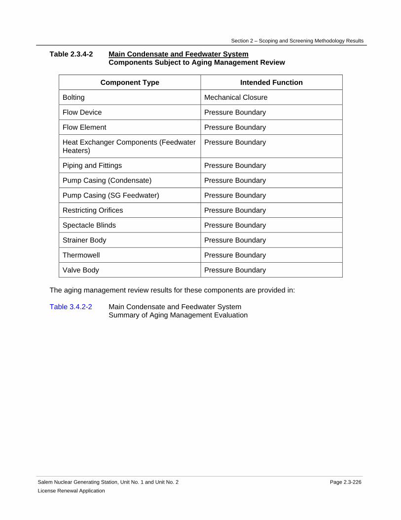
Section 2 – Scoping and Screening Methodology Results
Salem Nuclear Generating Station, Unit No. 1 and Unit No. 2 Page 2.3-226 License Renewal Application
Table 2.3.4-2 Main Condensate and Feedwater System Components Subject to Aging Management Review
Component Type Intended Function
Bolting Mechanical Closure
Flow Device Pressure Boundary
Flow Element Pressure Boundary
Heat Exchanger Components (Feedwater Heaters)
Pressure Boundary
Piping and Fittings Pressure Boundary
Pump Casing (Condensate) Pressure Boundary
Pump Casing (SG Feedwater) Pressure Boundary
Restricting Orifices Pressure Boundary
Spectacle Blinds Pressure Boundary
Strainer Body Pressure Boundary
Thermowell Pressure Boundary
Valve Body Pressure Boundary The aging management review results for these components are provided in: Table 3.4.2-2 Main Condensate and Feedwater System Summary of Aging Management Evaluation

Section 2 – Scoping and Screening Methodology Results
Salem Nuclear Generating Station, Unit No. 1 and Unit No. 2 Page 2.3-227 License Renewal Application
2.3.4.3 Main Condenser and Air Removal System
System Purpose The Main Condenser and Air Removal System is a normally operating mechanical system designed primarily to condense and deaerate steam from the main turbine. The Main Condenser and Air Removal System consists of two plant systems: main condenser and condenser air removal. The Main Condenser and Air Removal System is in scope for license renewal. However, portions of the Main Condenser and Air Removal System are not required to perform intended functions and are not in scope. The air removal portion of the Main Condenser and Air Removal System is not in the scope of license renewal. The purpose of the main condenser portion of the Main Condenser and Air Removal System is to recover water used in the steam cycle by condensing and deaerating unused steam. The Main Condenser and Air Removal System accomplishes this by transferring heat to the Circulating Water System (which is within the tube bundle of the condensers), collecting the condensate, and storing the condensate in the hotwell for reuse in the steam cycle. The purpose of the condenser air removal portions of the Main Condenser and Air Removal System is to allow the main condenser to operate at vacuum for peak efficiency. It accomplishes this by removing air and non-condensable gases from the main condensers using vacuum pumps during operation of the main turbine. The portion of the Main Condenser and Air Removal System that is in scope for license renewal is the hotwell portion of the Main Condenser and Air Removal System, which provides a backup source of water to the condensate pumps to maintain hot standby and plant cooldown following an Appendix R fire scenario when auxiliary feedwater is not available. System Operation The Main Condenser and Air Removal System is comprised of the steam side of the main condenser including the three condenser hotwells, the three condenser vacuum pumps, one priming tank vacuum pump, waterbox priming tank and the associated valves and piping. During normal operation, exhaust steam from the low-pressure turbines is discharged into the steam space of the main condenser. The steam spaces are interconnected on the three condenser sections. Within the main condenser, the steam passes over the outside of the circulating water-filled condenser tubes and forms condensate that enters the hotwell region of the condenser. Steam condensation creates the vacuum necessary for efficient turbine operation. The main vacuum pumps are provided to maintain a vacuum during operation of the main turbine by removing air and non-condensable gases from the main condensers. One vacuum pump takes suction from the waterbox priming tank, which maintains the circulator waterboxes filled. Because the main condenser and vacuum pumps operate under vacuum, the vacuum pumps are provided with seal water. The Demineralized Water System supplies seal water through seal water circulators from the separating tank to the vacuum pumps. During normal operation, only one vacuum pump is required to maintain condenser vacuum. Additional vacuum pumps are operated as required to maintain condenser vacuum.

Section 2 – Scoping and Screening Methodology Results
Salem Nuclear Generating Station, Unit No. 1 and Unit No. 2 Page 2.3-228License Renewal Application
For more detailed information, see UFSAR Section 10.4. System Boundary The boundary of the Main Condenser and Air Removal System begins at the low-pressure turbine exhaust shells and continues through the main condenser shell, over the condenser tubes, and ends at the hotwell. Two low-pressure heaters that are mounted in the neck of each condenser section also form a portion of the boundary. The condenser air removal is not in scope. The condenser air removal begins with two lines from each of the three condenser sections and combines into one steam space suction header. The vacuum pumps take suction from the header and discharge gases to the plant vent (atmosphere). Separated water is reused by the vacuum pumps. One vacuum pump takes suction only from the waterbox priming tank. Blank flanges in the steam space header prevent this pump from connecting to the steam space. Demineralized water supplies the condenser hotwell makeup system. Excess hotwell inventory is normally directed to the raw water storage basin, which is part of the Demineralized Water System. The condenser air removal portion of the Main Condenser and Air Removal System associated with establishing and maintaining main condenser vacuum, discharging these non-condensable gases from the condenser steam space and condensing steam is not required to support intended functions. This portion of the Main Condenser and Air Removal System is not included in the scope of license renewal. The only intended function of the Main Condenser and Air Removal System is to provide the hotwell water inventory as a water source for steam generator cooling during a loss of auxiliary feedwater Appendix R scenario. Therefore, the main condenser and hotwell are the only portions of this system in scope for license renewal. Not included in the Main Condenser and Air Removal System license renewal scoping boundary are the following interfacing systems, which are separately evaluated as license renewal systems: Circulating Water System Demineralized Water System Main Condensate and Feedwater System Main Steam System Main Turbine and Auxiliaries System Reason for Scope Determination The Main Condenser and Air Removal System is not in scope under 10 CFR 54.4(a)(1) because no portions of the system are safety-related and relied upon to remain functional during and following design basis events. The Main Condenser and Air Removal System is not in scope under 10 CFR 54.4(a)(2) because failure of nonsafety-related portions of the system would not prevent satisfactory accomplishment of function(s) identified for 10 CFR 54.4(a)(1). It meets 10 CFR 54.4(a)(3) because it is relied upon in the safety analyses or plant evaluations to perform a function that demonstrates compliance with the Commission's regulations for Fire Protection (10 CFR 50.48). The Main Condenser and Air Removal System is not relied upon in any safety analyses or plant evaluations to perform a function that

Section 2 – Scoping and Screening Methodology Results
Salem Nuclear Generating Station, Unit No. 1 and Unit No. 2 Page 2.3-229 License Renewal Application
demonstrates compliance with the Commission's regulation for Environmental Qualification (10 CFR 50.49), Pressurized Thermal Shock (10 CFR 50.61), Anticipated Transient Without Scram (10 CFR 50.62), or Station Blackout (10 CFR 50.63). System Intended Functions 1. Relied upon in safety analyses or plant evaluations to perform a function that demonstrates compliance with the Commission's regulations for Fire Protection (10 CFR 50.48). The Main Condenser and Air Removal System is credited for a supply of water for the condensate pump to maintain hot standby following on Appendix R fire scenario when auxiliary feedwater is not available. 10 CFR 54.4(a)(3) UFSAR References 10.4.1 10.4.2 License Renewal Boundary Drawings Unit 1: LR-205202 Sheet 1 LR-205203 Sheet 4 LR-205203 Sheet 5 LR-205203 Sheet 6 Unit 2: LR-205302 Sheet 1 LR-205303 Sheet 4 LR-205303 Sheet 5 LR-205303 Sheet 6 Unit Common: None

Section 2 – Scoping and Screening Methodology Results
Salem Nuclear Generating Station, Unit No. 1 and Unit No. 2 Page 2.3-230 License Renewal Application
Table 2.3.4-3 Main Condenser and Air Removal System Components Subject to Aging Management Review
Component Type Intended Function
Heat Exchanger Components (Main Condenser and Hotwell)
Pressure Boundary
The aging management review results for these components are provided in: Table 3.4.2-3 Main Condenser and Air Removal System Summary of Aging Management Evaluation

Section 2 – Scoping and Screening Methodology Results
Salem Nuclear Generating Station, Unit No. 1 and Unit No. 2 Page 2.3-231 License Renewal Application
2.3.4.4 Main Steam System
System Purpose The Main Steam System is a normally operating mechanical system designed to provide a flow path for the flow of saturated steam between the steam generator outlets to the high pressure turbine inlets. The Main Steam System also supplies saturated steam to steam dump system (turbine bypass), moisture separator reheaters, main steam coils, turbine gland seal system, turbine-driven auxiliary feedwater pump, steam generator feed pump turbines, and high pressure turbine cylinder heating steam. The Main Steam System is in scope for license renewal. However, portions of the Main Steam System are not required to perform intended functions and are not in scope. The Main Steam System has several interfaces with other systems that are not in the license renewal boundary of the Main Steam System. The purpose of the Main Steam System is to direct saturated steam from four steam generators to the high pressure turbines. It accomplishes its purpose by directing the steam generated by the steam generators into the high pressure turbine through piping and piping components. The turbine bypass portion bypasses a portion of full load flow directly from the main steam lines to the condenser. In addition, the bypass portion supplies steam to the main steam coils of the moisture separator reheaters, steam generator feed pump turbines (during low load operation) and the gland steam controller. The auxiliary feed pump turbine is fed from the Main Steam System and is safety-related. The moisture separator reheaters and gland steam controllers are evaluated with the Main Turbine and Auxiliaries System. Four pipes direct the steam from the steam generators, through the containment wall penetrations to an anchored mixing bottle in the yard. Following temperature and pressure equalization in the mixing bottle, steam flows to the turbine through two parallel pipes. Each of these pipes bifurcates to a pair of lines which supply the four sets of turbine stop and governor control valves. Piping interconnecting the two main steam pipes just upstream of their respective bifurcations provides equalization of steam pressure near the turbine. Main steam isolation valves are installed in each main steam line at the outlet of each steam generator. The valves are located outside of the containment, downstream of the safety valve manifold. The main steam isolation valves close automatically on the initiation of a steam line isolation signal. Flow limiters (venturi-type restrictor) are provided in each steam line. They are designed to increase the margin to departure from nucleate boiling (DNB), and thereby reduce fuel clad damage, by limiting steam flow rate consequent to a steam line rupture and thereby reducing the cooldown rate of the primary system. Flow limiters are also provided with steam flow transmitters, which provide inputs to the Reactor Protection System. System Operation The Main Steam System is comprised of flow restricting nozzles, safety valves, atmospheric relief valves, main steam isolation valves, mixing bottle and the necessary piping, valves and instrumentation designed to provide steam to the high pressure turbine to accomplish its

Section 2 – Scoping and Screening Methodology Results
Salem Nuclear Generating Station, Unit No. 1 and Unit No. 2 Page 2.3-232License Renewal Application
design functions. The Main Steam System delivers steam from each of the four steam generators via piping, through containment penetrations, to the mixing bottle in the yard and ultimately to the high-pressure turbine. Two steam generator lines provide steam to the auxiliary feed pump turbines. From the outlet of the mixing bottle two main steam lines carry steam toward the main turbine. An equalizing line connects the two parallel main steam lines near the main turbine. A turbine bypass header taps off each main steam pipe to supply the following loads: moisture separator reheaters, main steam coils, steam dump, gland seals and steam generator feed pump turbines. Each of the main steam pipes splits to supply the four high pressure turbine nozzles. At the high pressure turbine inlet, each pipe has a turbine stop valve and a governor valve. Distribution of steam to the Main Turbine and Auxiliaries System is accomplished through branch connections downstream of the mixing bottle located in the yard area. The Main Steam System provides the pressure relief function through the safety valves installed on the main steam lines. They provide over-pressure protection for the steam generators and steam piping upstream of the main steam isolation valves and prevent steam pressure from exceeding pressure limits on loss of turbine load with no reactor trip and no steam dump operation. Each of the four main steam lines contain an atmospheric relief valve that provides alternate controllable plant cooldown capability by discharging steam to atmosphere when the steam dump and/or condensers are not available. It also prevents the safety valves actuation during minor transients. These valves are not required to perform any safety function. If a safety valve lifts, these valves can be used to reduce pressure, allowing the safety valves to reseat. For more detailed information, see UFSAR Section 10.3.2. System Boundary The Main Steam System boundary begins at the four steam generator outlets, continues through the Containment Structure, Penetration Area, Auxiliary Building, Yard, Turbine Building and ends at the connections to the high pressure turbine and the condenser. The boundary also includes the flow measuring and flow restricting nozzles, safety valves, atmospheric relief valves, main steam isolation valves, mixing bottle, and turbine stop valves. The boundary includes the steam supply for the auxiliary feedwater pump turbines on two of the main steam lines. The boundary ends at the inlet of the manual steam isolation valves to the Auxiliary Feedwater System. The boundary includes the main steam turbine bypass line which supplies steam to the gland seal and the main steam coils in the moisture separator reheaters which are evaluated with the Main Turbine and Auxiliaries System. The boundary for the high pressure steam supply to the steam generator feedwater pump turbines begins at the main steam line on the west side of the turbine and ends at the inlet to the steam generator feedwater pump turbine. Downstream of the main steam and turbine bypass lines, each main steam line continues towards its corresponding turbine stop valve, and governor control valve to the inlet connection on the high pressure turbine. Turbine by-pass steam ends at the inlets to the main condenser.

Section 2 – Scoping and Screening Methodology Results
Salem Nuclear Generating Station, Unit No. 1 and Unit No. 2 Page 2.3-233 License Renewal Application
All associated piping, components and instrumentation contained within the flow path described above are included in the system evaluation boundary. Also included in the Main Steam System license renewal scoping boundary are those portions of nonsafety-related piping and equipment that extend beyond the safety-related/nonsafety-related interface up to the location of the first seismic anchor, or to a point no longer in proximity to equipment performing a safety-related function, whichever extends furthest. Included in this boundary are pressure-retaining components relied upon to preserve the leakage boundary intended function of this portion of the system. For more information, refer to the license renewal boundary drawing for identification of this boundary, shown in red. Not included in the Main Steam System license renewal scoping boundaries are the following interfacing systems, which are separately evaluated as license renewal systems: Auxiliary Feedwater System Main Turbine and Auxiliaries System Radiation Monitoring System Sampling System Steam Generators Reason for Scope Determination The Main Steam System meets 10 CFR 54.4(a)(1) because portions of the system are safety-related and are relied upon to remain functional during and following design basis events. It meets 10 CFR 54.4(a)(2) because failure of nonsafety-related portions of the system could prevent satisfactory accomplishment of function(s) identified for 10 CFR 54.4(a)(1). It also meets 10 CFR 54.4(a)(3) because it is relied upon in safety analyses or plant evaluations to perform a function that demonstrates compliance with the Commission's regulations for Fire Protection (10 CFR 50.48), Environmental Qualification (10 CFR 50.49), Anticipated Transients Without Scram (10 CFR 50.62), and Station Blackout (10 CFR 50.63). The Main Steam System is not relied upon in any safety analyses or plant evaluations to perform a function that demonstrates compliance with the Commission's regulation for Pressurized Thermal Shock (10 CFR 50.61). System Intended Functions 1. Sense process conditions and generate signals for containment isolation. The main steam line includes instrumentation that detects, mitigates, and actuates automatic safety functions. 10 CFR 54.4(a)(1) 2. Remove residual heat from the reactor coolant system. The atmospheric relief valves provide remote pressure control of the steam generator secondary side and main steam safety valves provide pressure relief to prevent steam generator overpressurization. 10 CFR 54.4(a)(1) 3. Provide primary containment boundary. The main steam isolation valves close automatically on isolation signals from the Reactor Protection System. 10 CFR 54.4(a)(1) 4. Provide secondary heat sink. The condenser steam dump acts as a supplemental heat sink for a load reduction without a reactor trip. Should the condenser not be available as a heat

Section 2 – Scoping and Screening Methodology Results
Salem Nuclear Generating Station, Unit No. 1 and Unit No. 2 Page 2.3-234License Renewal Application
sink, the safety valves and atmospheric relief valves will open to dump steam to the atmosphere. 10 CFR 54.4(a)(1) 5. Resist nonsafety-related SSC failure that could prevent satisfactory accomplishment of a safety related function. Nonsafety-related piping and components, located downstream of the main steam isolation valves and in proximity to equipment that performs safety-related functions, are required to maintain leakage boundary integrity to preclude spatial interaction with the safety-related equipment. 10 CFR 54.4(a)(2) 6. Relied upon in safety analyses or plant evaluations to perform a function that demonstrates compliance with the Commission's regulations for Fire Protection (10 CFR 50.48). The main steam isolation valves and safety valves are relied upon in the Post Fire Safe Shutdown Analysis. 10 CFR 54.4(a)(3) 7. Relied upon in the safety analysis or plant evaluations to perform a function that demonstrates compliance with the Commission's regulations for Environmental Qualification (10 CFR 50.49). The safety valves are expected to operate in a harsh environment. 10 CFR 54.4(a)(3) 8. Relied upon in the safety analysis or plant evaluations to perform a function that demonstrates compliance with the Commission's regulations for Anticipated Transients Without Scram (10 CFR 50.62). Provides turbine inlet steam pressure input to AMSAC. 10 CFR 54.4(a)(3) 9. Relied upon in safety analyses or plant evaluations to perform a function that demonstrates compliance with the Commission's regulations for Station Blackout (10 CFR 50.63). The main steam isolation valves going closed and the safety valves being available for pressure control are credited in the SBO analysis. 10 CFR 54.4(a)(3) UFSAR References 10.2.2 10.3.2 10.4.4 License Renewal Boundary Drawings Unit 1: LR-205203 Sheet 1 LR-205203 Sheet 2 LR-205203 Sheet 3 LR-205203 Sheet 4 LR-205203 Sheet 5 LR-205203 Sheet 6 Unit 2: LR-205303 Sheet 1 LR-205303 Sheet 2 LR-205303 Sheet 3 LR-205303 Sheet 4
Section 2 – Scoping and Screening Methodology Results
Salem Nuclear Generating Station, Unit No. 1 and Unit No. 2 Page 2.3-235License Renewal Application
LR-205303 Sheet 5 LR-205303 Sheet 6 Unit Common: None
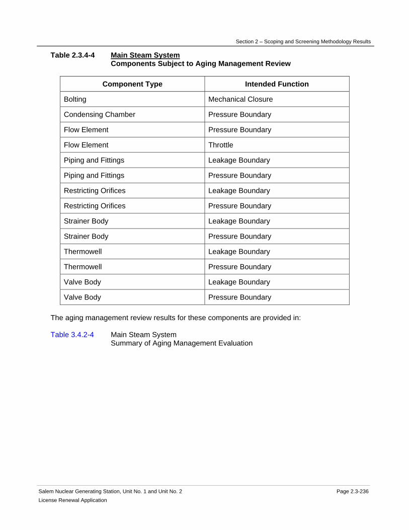
Section 2 – Scoping and Screening Methodology Results
Salem Nuclear Generating Station, Unit No. 1 and Unit No. 2 Page 2.3-236 License Renewal Application
Table 2.3.4-4 Main Steam System Components Subject to Aging Management Review
Component Type Intended Function
Bolting Mechanical Closure
Condensing Chamber Pressure Boundary
Flow Element Pressure Boundary
Flow Element Throttle
Piping and Fittings Leakage Boundary
Piping and Fittings Pressure Boundary
Restricting Orifices Leakage Boundary
Restricting Orifices Pressure Boundary
Strainer Body Leakage Boundary
Strainer Body Pressure Boundary
Thermowell Leakage Boundary
Thermowell Pressure Boundary
Valve Body Leakage Boundary
Valve Body Pressure Boundary The aging management review results for these components are provided in: Table 3.4.2-4 Main Steam System Summary of Aging Management Evaluation

Section 2 – Scoping and Screening Methodology Results
Salem Nuclear Generating Station, Unit No. 1 and Unit No. 2 Page 2.3-237 License Renewal Application
2.3.4.5 Main Turbine and Auxiliaries System
System Purpose The Main Turbine and Auxiliaries System is a normally operating mechanical system designed to utilize steam from the Main Steam System to provide motive force for the main generator to generate electrical power for distribution to the grid. The Main Turbine and Auxiliaries System consists of the following plant systems: turbine electrohydraulic control, gland sealing steam and leak off (turbine), moisture separator reheater steam and drains, turbine auxiliaries cooling, turbine drains, main turbine lube oil, and the main turbine. The Main Turbine and Auxiliaries System is in scope for license renewal. However, portions of the Main Turbine and Auxiliaries System associated with the gland sealing steam and leak off (turbine), moisture separator reheater steam and drains, turbine auxiliaries cooling, turbine drains, main turbine lube oil, and the main turbine are not required to perform intended functions and are not in scope. The Main Turbine and Auxiliaries System has interfaces with several other systems and components that are not within the license renewal boundary of the Main Turbine and Auxiliaries System, and are evaluated separately. These include the Fresh Water System, Main Condensate and Feedwater System, Main Condenser and Air Removal System, Main Generator and Auxiliaries System, Main Steam System, Reactor Protection System, and the Service Water System. The overall purpose of the Main Turbine and Auxiliaries System is to provide motive force for the main generator to generate electrical power for distribution to the grid. The purpose of the turbine electrohydraulic control system is to control turbine valve movement, which in turn controls main steam flow at the inlet to the main turbine. This system also provides trip functions for the main turbine. The turbine electrohydraulic control system accomplishes this purpose with pumps, reservoirs, heat exchangers, piping, piping components, and valves. The purpose of the gland sealing steam and leak off (turbine) system is to use main steam to seal the annular openings where the main turbine shaft emerges from the casings, preventing steam outleakage and air inleakage along the shaft. The gland sealing steam and leak off (turbine) system accomplishes its purpose with piping, piping components, and valves. The purpose of the moisture separator reheater steam and drains system is to dry and reheat main steam from the outlet of the high pressure turbine and supply it to the low pressure turbines to increase cycle efficiency. The moisture separator reheater steam and drains system accomplishes its purpose with moisture separator reheaters, heat exchangers, piping, and piping components. The purpose of the turbine auxiliaries cooling system is to provide cooling water to the turbine generator auxiliary components, as well as other plant components. The turbine auxiliaries cooling system accomplishes this purpose with tanks, heat exchangers, pumps, piping, piping components, and valves.

Section 2 – Scoping and Screening Methodology Results
Salem Nuclear Generating Station, Unit No. 1 and Unit No. 2 Page 2.3-238 License Renewal Application
The purpose of the turbine drains system is to collect condensation from each of the main steam lines, turbine bypass lines, gland sealing steam lines, and steam generator feed pump turbines and forward it to the main condenser. The turbine drains system accomplishes this purpose with piping, piping components, and valves. The purpose of the main turbine lube oil system is to provide lubrication of the turbine generator bearings. The main turbine lube oil system accomplishes its purpose with pumps, filters, tanks, heat exchangers, piping, piping components, and valves. The purpose of the main turbine system is to convert thermal energy of the main steam system into mechanical energy to drive the main generator. The main turbine system accomplishes its purpose with a high pressure turbine and three low pressure turbines. System Operation The Main Turbine and Auxiliaries System is comprised of the following major components: high pressure turbine, low pressure turbines, pumps, heat exchangers, tanks, valves, and piping components. For the turbine electrohydraulic control system, flow of synthetic oil begins at the oil reservoir where flow to the electrohydraulic pumps continues through inline filters and to a distribution system consisting of valves and piping components. The distribution piping provides electrohydraulic pressure to the turbine valves. A sidestream passes through media and particulate filters and back into the reservoir. High pressure accumulators are provided to act as passive hydraulic shock absorbers for the system. A portion of the flow is directed to heat exchangers cooled by the turbine auxiliaries cooling system. During a turbine trip, the electrohydraulic trip valves open to permit flow to the reservoir, de-pressurizing the system, causing the main turbine valves to close. For the gland sealing steam and leak off (turbine) system, flow of main steam from the turbine bypass headers and leak off from the steam generator feedpumps continues to the high pressure and low pressure turbine glands. Exhausted sealing steam flows to the gland steam condenser that is cooled by the turbine auxiliaries cooling system. Cooled condensate continues to the miscellaneous condensate return tank. For Salem Unit 2 only, gland sealing steam is also supplied to the moisture separator reheater relief valves until the moisture separator reheaters are pressurized. For the moisture separator reheater steam and drains system, flow begins from the exhaust of the last stage of the high pressure turbine and enters the moisture separator reheaters which are heated by both main steam and bleed steam. Flow continues through the moisture separator reheaters to remove condensate from the high pressure turbine exhaust steam and superheat the high pressure turbine exhaust steam. Steam flow continues to the low pressure turbines. Condensate from the moisture separator reheaters flows to the heater drain tank. For the turbine auxiliaries cooling system, flow begins at the make-up tank, continues through the turbine auxiliaries cooling pumps to the turbine auxiliaries cooling heat exchangers that are cooled by the non-nuclear portion of the Service Water System. Cooling water flows through the gland steam condenser, bleed steam coil drain pump seal coolers, lube oil coolers, and stuffing boxes, heater drain pump stuffing box jackets and pump motor upper bearing coolers, main condensate pump motor bearing coolers, vacuum pump seal water coolers, hydrogen coolers, exciter coolers, hydrogen side and air side seal oil coolers, main bus air coolers, and
Section 2 – Scoping and Screening Methodology Results
Salem Nuclear Generating Station, Unit No. 1 and Unit No. 2 Page 2.3-239 License Renewal Application
stator water coolers, and back to the suction of the turbine auxiliaries cooling pumps. For the turbine drains system, flow begins at each of the main steam lines, turbine bypass lines, gland sealing steam lines, and steam generator feed pump turbines and continues to the main condenser. For the main turbine lube oil system, flow begins at the turbine oil storage tanks and make-up tank, through the turbine oil transfer pump to a series of filters. Flow continues from the filters to the turbine oil reservoir. Flow continues from the reservoir to the main oil pump via an ejector. The discharge of the main oil pump provides motive force for the ejector, provides back-up flow to the high pressure turbine seal oil, and flow to the overspeed trip oil valve. Bearing oil flow begins at the reservoir, continues through the turbine oil coolers that are cooled by the non-nuclear portion of the Service Water System, to the main turbine bearings. From the bearings, oil flow continues through the guard pipe back to the reservoir via the oil return tray and basket strainer. A sidestream filter skid with circulating pumps is provided to filter oil in the reservoir. During start-up and shutdown conditions, turbine oil flow begins at the reservoir through the auxiliary oil pumps through the oil coolers to the suction of the bearing oil hydraulic lift pumps to the turbine bearings. An emergency bearing oil lift pump and a booster pump are also provided to provide bearing oil flow as required. For the main turbine system, steam flow begins at the inlet to the high pressure turbine and continues to the moisture separator reheaters. Steam flow continues from the moisture separator reheaters into the low pressure turbines and exhausts to the main condenser. For more detailed information, see UFSAR Sections 3.5.4, 10.2.2, 10.2.7, 10.3.2, 10.4.3, and 9.2.1. System Boundary The license renewal scoping boundary of the Main Turbine and Auxiliaries System begins at the emergency trip valve and trip solenoid valves in the turbine electrohydraulic control system and ends at the electrohydraulic reservoir. The remaining portions of the turbine electrohydraulic control system do not perform intended functions and are not in scope for license renewal. The following Main Turbine and Auxiliaries plant systems are not required to perform intended functions and are not in scope for license renewal: gland sealing steam and leak off (turbine), moisture separator reheater steam and drains, turbine auxiliaries cooling, turbine drains, main turbine lube oil, and the main turbine. Not included in the Main Turbine and Auxiliaries System license renewal scoping boundaries are the following interfacing systems, which are separately evaluated as license renewal systems: Fresh Water System Main Condensate and Feedwater System Main Condenser and Air Removal System Main Generator and Auxiliaries System Main Steam System Reactor Protection System Service Water System

Section 2 – Scoping and Screening Methodology Results
Salem Nuclear Generating Station, Unit No. 1 and Unit No. 2 Page 2.3-240 License Renewal Application
Reason for Scope Determination The Main Turbine and Auxiliaries System is not in scope under 10 CFR 54.4(a)(1) because no portions of the system are safety-related or relied upon to remain functional during and following design basis events. The Main Turbine and Auxiliaries System is not in scope under 10 CFR 54.4(a)(2) because failure of nonsafety-related portions of the system would not prevent satisfactory accomplishment of function(s) identified for 10 CFR 54.4(a)(1). The system is in scope under 10 CFR 54.4(a)(3) because it is relied upon in safety analyses or plant evaluations to perform a function that demonstrates compliance with the Commission's regulations for Anticipated Transient Without Scram (10 CFR 50.62). The system is not relied upon in safety analyses or plant evaluations to perform a function that demonstrates compliance with the Commission's regulations for Fire Protection (10 CFR 50.48), Environmental Qualification (10 CFR 50.49), Pressurized Thermal Shock (10 CFR 50.61), or Station Blackout (10 CFR 50.63). System Intended Functions 1. Relied upon in safety analyses or plant evaluations to perform a function that demonstrates compliance with the Commission's regulations for Anticipated Transient Without Scram (10 CFR 50.62). The turbine electrohydraulic control system of the Main Turbine and Auxiliaries System contains valves that actuate upon receipt of an ATWS signal. 10 CFR 54.4(a)(3) UFSAR References 3.5.4 10.2.2 10.2.7 10.3.2 10.4.3 9.2.1 License Renewal Boundary Drawings Unit 1: LR-226948 Sheet 1 Unit 2: LR-240688 Sheet 1 Unit Common: None

Section 2 – Scoping and Screening Methodology Results
Salem Nuclear Generating Station, Unit No. 1 and Unit No. 2 Page 2.3-241 License Renewal Application
Table 2.3.4-5 Main Turbine and Auxiliaries System Components Subject to Aging Management Review
Component Type Intended Function
Bolting Mechanical Closure
Piping and Fittings Pressure Boundary
Valve Body Pressure Boundary The aging management review results for these components are provided in: Table 3.4.2-5 Main Turbine and Auxiliaries System Summary of Aging Management Evaluation
Section 2 – Scoping and Screening Methodology Results
Salem Nuclear Generating Station, Unit No. 1 and Unit No. 2 Page 2.4-1 License Renewal Application
2.4 SCOPING AND SCREENING RESULTS: CONTAINMENT, STRUCTURES, AND COMPONENT SUPPORTS
The following structural components are addressed in this section:
• Auxiliary Building (2.4.1)
• Component Supports Commodity Group (2.4.2)
• Containment Structure (2.4.3)
• Fire Pump House (2.4.4)
• Fuel Handling Building (2.4.5)
• Office Buildings (2.4.6)
• Penetration Areas (2.4.7)
• Pipe Tunnel (2.4.8)
• Piping and Component Insulation Commodity Group (2.4.9)
• SBO Compressor Building (2.4.10)
• Service Building (2.4.11)
• Service Water Accumulator Enclosures (2.4.12)
• Service Water Intake (2.4.13)
• Shoreline Protection and Dike (2.4.14)
• Switchyard (2.4.15)
• Turbine Building (2.4.16)
• Yard Structures (2.4.17)

Section 2 – Scoping and Screening Methodology Results
Salem Nuclear Generating Station, Unit No. 1 and Unit No. 2 Page 2.4-2 License Renewal Application
2.4.1 Auxiliary Building
Structure Purpose The Auxiliary Building, which includes the inner penetration areas, is a reinforced concrete structure located between the Salem Generating Stations (SGS) Unit 1 and Unit 2 containment structures. The Auxiliary Building is a multi-story structure; approximately 215 by 330 feet in plan area, comprised of reinforced concrete walls, slabs, foundation mat, roof, masonry walls, and structural steel. The reinforced concrete foundation mat is supported on a lean concrete fill bearing directly on the Vincentown Formation. The roof is a reinforced concrete slab with concrete fill over liquid membrane waterproofing. Built up roofing over reinforced concrete also exists in certain areas. The building roof supports a concrete penthouse and missile shields for diesel intake, exhaust, and building ventilation. The building roof also supports hatches, blowout panels, and an elevator shaft extension. The Auxiliary Building is classified as a Category I (seismic) structure designed to maintain its structural integrity during and following postulated design basis accidents and extreme environmental conditions. The Auxiliary Building is divided into compartments designed to protect SGS Unit 1 and Unit 2 safety-related systems and components and provide physical separation for redundant mechanical and electrical components. Among these compartments are the inner penetration areas, the control room envelope, emergency diesel generator rooms, and the radwaste area. The inner penetration area for each unit is located adjacent to and seismically separated from its Containment Structure. The inner penetration area for each unit is partitioned into compartments for electrical and mechanical penetrations into the containment. The penetration areas design includes blowout panels to maintain the internal pressure of the areas within acceptable limits following the postulated main steam and feedwater system ruptures. The inner penetration area roof supports a raised concrete extension to provide for increased blowout panel area. The common control room envelope consists of the control room (with an area for each unit), data logging rooms, operator ready room, conference room or operations support center (OSC), control room supervisor platform area, and the operations superintendent office. The control room contains controls and instrumentation necessary for operation of SGS Unit 1 and Unit 2 under normal and abnormal conditions. The facilities located within the control room envelope are designed to be habitable throughout the course of a design basis accident (DBA) and the resulting radiological condition. The Auxiliary Building includes rooms for three emergency diesel generators (EDGs) for each unit and their auxiliary systems. Two fuel oil tanks for each unit are located in the floor below the diesels. Each diesel generator has its own fuel oil day tank mounted above the unit for gravity feed. The diesel generators are isolated from each other and from other equipment in the area by firewalls and fire doors. The radwaste area includes rooms and compartments which contain Radwaste System components designed to collect, process, store, and prepare for disposal liquid, gaseous and solid waste. Storage areas are shielded to protect personnel in accessible portions of the solid radwaste areas to meet the requirements of 10 CFR 20.

Section 2 – Scoping and Screening Methodology Results
Salem Nuclear Generating Station, Unit No. 1 and Unit No. 2 Page 2.4-3 License Renewal Application
The Residual Heat Removal sumps and Residual Heat Removal pumps for SGS Unit 1 and Unit 2 are contained within the Auxiliary Building at the lowest elevation. The sumps are lined with a carbon steel liner for leak tightness. The purpose of the Auxiliary Building is to provide structural support, shelter and protection to systems, structures, and components (SSCs) housed within the building during normal plant operation, and during and following postulated design basis accidents and extreme environmental conditions. These functions are provided to portions of engineered safety features systems, auxiliary systems, steam and power conversion systems, and control systems. The building also contains the control room, which is the main operation center for the plant providing a centralized area for control and monitoring of safety-related equipment. The control room in conjunction with Control Area Ventilation System provides a habitable environment for plant operators so that the plant can be safely operated and shutdown under design basis accident conditions. The Auxiliary Building also supports and protects nonsafety-related equipment including chemistry lab equipment. The Auxiliary Building is maintained under a slight negative pressure to control the release of particulate and gaseous contamination from the building. Included in the boundary of the Auxiliary Building are reinforced concrete elements of the building, cable trays, concrete embedments, masonry walls, doors, hatches, compressible joints and seals, conduit, expansion or control joints, racks, frames, enclosures, structural steel, miscellaneous steel, bolting, penetration sleeves, penetration seals, pipe whip restraints, missile shields, pipe encapsulation sleeves, spray shields, residual heat removal sump pit and liner, pipe alley and trench, roofing membrane, and tube track. Also included in the boundary of this structure are the blowout panels, the roof blowout panel extension, the roof missile shields for diesel intake, exhaust and building ventilation, and the air discharge penthouse. Assessment of the Auxiliary Building boundary concluded that the building is in scope of license renewal in its entirety. Refer to the "Components Subject to Aging Management Review" table below for a complete list of components included in the boundary of the Auxiliary Building. Not included in the boundary of the Auxiliary Building are cranes and hoists, fire barriers, plant vent, mechanical and electrical containment penetrations, piping and component insulation, diesel exhaust and air intake components, and component supports. The plant vent which exits the Auxiliary Building and extends up the outside of the Containment Structure is evaluated separately with the Auxiliary Building Ventilation System. Mechanical and electrical penetrations into the containment are evaluated separately with the Containment Structure. Diesel exhaust and air intake components are evaluated separately with the Emergency Diesel Generator & Auxiliaries System. Piping and component insulation are evaluated separately with the Piping and Component Insulation Commodity Group. Cranes and hoists are evaluated separately with the Cranes and Hoists system, fire barriers are evaluated separately with the Fire Protection System, and the component supports are evaluated with the Component Supports Commodity Group. For more detailed information, see UFSAR Section 3.2.1.2, 3.6.5.10, and 9.4.2.2.1. Reason for Scope Determination The Auxiliary Building meets 10 CFR 54.4(a)(1) because it is a safety-related structure that is relied on to remain functional during and following design basis events. It meets 10 CFR 54.4(a)(2) because the building provides physical support, shelter, and protection for

Section 2 – Scoping and Screening Methodology Results
Salem Nuclear Generating Station, Unit No. 1 and Unit No. 2 Page 2.4-4 License Renewal Application
nonsafety-related systems, structures, and components (SSCs) whose failure could prevent satisfactory accomplishment of function(s) identified for 10 CFR 54.4(a)(1). It also meets 10 CFR 54.4(a)(3) because it provides physical support, shelter and protection for systems, structures, and components (SSCs) relied upon in safety analyses or plant evaluations to perform a function that demonstrates compliance with the Commission's regulations for Fire Protection (10 CFR 50.48), Environmental Qualification (10 CFR 50.49), Anticipated Transients Without Scram (10 CFR 50.62), and Station Blackout (10 CFR 50.63). The Auxiliary Building is not relied upon in any safety analyses or plant evaluations to perform a function that demonstrates compliance with the Commission's regulations for Pressurized Thermal Shock (10 CFR 50.61). System Intended Functions 1. Provides physical support, shelter, and protection for safety-related systems, structures, and components (SSCs). 10 CFR 54.4(a)(1) 2. Provide centralized area for control and monitoring of nuclear safety-related equipment. 10 CFR 54.4(a)(1) 3. Provides physical support, shelter, and protection for nonsafety-related systems, structures, and components (SSCs) whose failure could prevent satisfactory accomplishment of function(s) identified for 10 CFR 54.4 (a)(1). 10 CFR 54.4(a)(2) 4. Provides physical support, shelter, and protection for systems, structures, and components relied upon in safety analyses or plant evaluations to perform a function that demonstrates compliance with the Commission's regulations for Fire Protection (10 CFR 50.48). 10 CFR 54.4(a)(3) 5. Provides physical support, shelter, and protection for systems, structures, and components relied upon in safety analyses or plant evaluations to perform a function that demonstrates compliance with the Commission's regulations for Environmental Qualification (10 CFR 50.49). 10 CFR 54.4(a)(3) 6. Provides physical support, shelter, and protection for systems, structures, and components relied upon in safety analyses or plant evaluations to perform a function that demonstrates compliance with the Commission's regulations for Anticipated Transients Without Scram (10 CFR 50.62). 10 CFR 54.4(a)(3) 7. Provides physical support, shelter, and protection for systems, structures, and components relied upon in safety analyses or plant evaluations to perform a function that demonstrates compliance with the Commission's regulations for Station Blackout (10 CFR 50.63). 10 CFR 54.4(a)(3) UFSAR References 1.3.1 2.4.1 3.2.1.2 3.4.3 3.6.5 3.8.4.5.1

Section 2 – Scoping and Screening Methodology Results
Salem Nuclear Generating Station, Unit No. 1 and Unit No. 2 Page 2.4-5 License Renewal Application
6.4 8.3.1.5 9.3 9.4.2.2.1 15.3.7 License Renewal Boundary Drawings LR-204802

Section 2 – Scoping and Screening Methodology Results
Salem Nuclear Generating Station, Unit No. 1 and Unit No. 2 Page 2.4-6 License Renewal Application
Table 2.4-1 Auxiliary Building Components Subject to Aging Management Review
Component Type Intended Function
Blowout Panel Pressure Relief
Blowout Panel Shelter, Protection
Bolting (Structural) Structural Support
Cable Trays Structural Support
Compressible Joints and Seals (Seismic Gap)
Expansion / Separation
Concrete Curbs Direct Flow
Concrete anchors Structural Support
Concrete embedments Structural Support
Concrete: Above-grade exterior Flood Barrier
Concrete: Above-grade exterior Missile Barrier
Concrete: Above-grade exterior Shelter, Protection
Concrete: Above-grade exterior Structural Support
Concrete: Below-grade exterior Flood Barrier
Concrete: Below-grade exterior Missile Barrier
Concrete: Below-grade exterior Shelter, Protection
Concrete: Below-grade exterior Structural Support
Concrete: Foundation Flood Barrier
Concrete: Foundation Shelter, Protection
Concrete: Foundation Structural Support
Concrete: Interior Flood Barrier
Concrete: Interior HELB/MELB Shielding
Concrete: Interior Missile Barrier
Concrete: Interior Shelter, Protection
Concrete: Interior Shielding
Concrete: Interior Structural Support

Section 2 – Scoping and Screening Methodology Results
Salem Nuclear Generating Station, Unit No. 1 and Unit No. 2 Page 2.4-7 License Renewal Application
Component Type Intended Function
Conduit Shelter, Protection
Conduit Structural Support
Doors Flood Barrier
Doors HELB/MELB Shielding
Doors Missile Barrier
Doors Shelter, Protection
Equipment foundations Structural Support
Hatches/Plugs HELB/MELB Shielding
Hatches/Plugs Missile Barrier
Hatches/Plugs Shelter, Protection
Hatches/Plugs Shielding
Hatches/Plugs Structural Support
Masonry walls: Interior Shelter, Protection
Masonry walls: Interior Shielding
Masonry walls: Interior Structural Support
Miscellaneous steel (catwalks, stairs, handrails, ladders, vents and louvers, platforms, etc.)
Shelter, Protection
Miscellaneous steel (catwalks, stairs, handrails, ladders, vents and louvers, platforms, etc.)
Structural Support
Panels, Racks, Cabinets, and Other Enclosures
Structural Support
Penetration seals Flood Barrier
Penetration seals HELB/MELB Shielding
Penetration seals Shelter, Protection
Penetration seals Shielding
Penetration sleeves Flood Barrier
Penetration sleeves HELB/MELB Shielding

Section 2 – Scoping and Screening Methodology Results
Salem Nuclear Generating Station, Unit No. 1 and Unit No. 2 Page 2.4-8 License Renewal Application
Component Type Intended Function
Penetration sleeves Structural Support
Pipe Whip Restraints and Jet Impingement Shields (including Pipe Encapsulation and Spray Shields)
HELB/MELB Shielding
Pipe Whip Restraints and Jet Impingement Shields (including Pipe Encapsulation and Spray Shields)
Pipe Whip Restraint
Roofing membrane Shelter, Protection
Seals, gaskets, and moisture barriers (caulking, flashing and other sealants)
Flood Barrier
Seals, gaskets, and moisture barriers (caulking, flashing and other sealants)
Shelter, Protection
Steel components: All structural steel Missile Barrier
Steel components: All structural steel Structural Support
Steel components: Sump Screen Trench Cover
Structural Support
Steel elements: Liner; Liner anchors; Integral attachments
Water retaining boundary
Tube Track Structural Support The aging management review results for these components are provided in: Table 3.5.2-1 Auxiliary Building Summary of Aging Management Evaluation

Section 2 – Scoping and Screening Methodology Results
Salem Nuclear Generating Station, Unit No. 1 and Unit No. 2 Page 2.4-9 License Renewal Application
2.4.2 Component Supports Commodity Group
Structure Purpose The Component Supports Commodity Group consists of structural elements and specialty components designed to transfer the load applied from a system, structure, or component (SSC) to the building structural element or directly to the building foundation. Supports include seismic anchors or restraints, frames, constant and variable spring hangers, rod hangers, sway struts, guides, stops, design clearances, straps, clamps, and clevis pins. Specialty components include snubbers, sliding surfaces, and vibration isolation elements. The commodity group is comprised of the following supports: - Supports for ASME Class 1, 2 and 3 piping and components, including reactor pressure vessel support shoes, steam generator supports, pressurizer supports, and reactor coolant pump supports. - Supports for cable trays, conduits, HVAC ducts, tube tracks, instrument tubing and non-ASME piping and components. - Supports for racks, panels, cabinets and enclosures for electrical equipment and instrumentation. - Supports for emergency diesel generators (EDG), HVAC system components, and other miscellaneous mechanical equipment. - Supports for platforms, pipe whip restraints, jet impingement shields, masonry walls, and other miscellaneous structures. The purpose of a support is to transfer gravity, thermal, seismic, and other lateral loads imposed on or by the system, structure, or component to the supporting building structural element or foundation. Sliding surfaces, when incorporated into the support design, permit release of lateral forces but are relied upon to carry vertical load. Specialty supports such as snubbers only resist seismic forces. Vibration isolation elements are incorporated in the design of some vibrating equipment to minimize the impact of vibration. Other support types such as guides and position stops allow displacement in a specified direction or preclude unacceptable movements and interactions. Included in the boundary of the Component Supports Commodity Group are supports for SSCs in scope for license renewal. The commodity group also includes supports for SSCs that are not in scope for license renewal, but their supports are required to restrain or prevent physical interaction with safety-related SSCs (e.g. seismic II/I). The supports include building concrete at locations of expansion and grouted anchors, grout pads for support base plates, high strength bolting, constant and variable load spring hangers, guides, stops, sliding surfaces, support members, welds, bolted connections, support anchorages to building structures, and vibration isolation elements. Snubbers are also included in the boundary of this commodity group; however, they are considered active components and are not subject to aging management review except for the end connections, which perform a passive function for structural support. Refer to "Components Subject to Aging Management Review" table below for a complete list of components included in the boundary of the Component Supports Commodity Group.

Section 2 – Scoping and Screening Methodology Results
Salem Nuclear Generating Station, Unit No. 1 and Unit No. 2 Page 2.4-10 License Renewal Application
Not included in the boundary of the Component Supports Commodity Group are concrete pedestals and concrete frames, concrete embedments, and concrete anchors used for components other than supports listed herein. These commodities are evaluated separately with the license renewal structure that contains them. For more detailed information, see UFSAR Sections 3.7.3, 3.9, 5.2, 5.5.14. Reason for Scope Determination The Component Supports Commodity Group meets 10 CFR 54.4(a)(1) because it has safety-related supports that are relied upon to remain functional during and following design basis events. The Component Support Commodity Group meets 10 CFR 54.4(a)(2) because failure of nonsafety-related supports could prevent satisfactory accomplishment of function(s) identified for 10 CFR 54.4(a)(1). It also meets 10 CFR 54.4(a)(3) because some supports are relied upon in safety analyses or plant evaluations to perform a function that demonstrates compliance with the Commission's regulations for Fire Protection (10 CFR 50.48), Environmental Qualification (10 CFR 50.49), Anticipated Transients Without Scram (10 CFR 50.62), and Station Blackout (10 CFR 50.63). The Component Supports Commodity Group is not relied upon in any safety analyses or plant evaluations to perform a function that demonstrates compliance with the Commission's regulation for Pressurized Thermal Shock (10 CFR 50.61). System Intended Functions 1. Provides structural support or restraint to SSCs in the scope of license renewal. 10 CFR 54.4 (a)(1), (a)(2), (a)(3) 2. Provides structural support or restraint to SSCs not in the scope of license renewal to prevent interaction with safety-related SSCs. 10 CFR 54.4 (a)(2) UFSAR References 3.7.3 3.9 5.2 5.5.14 License Renewal Boundary Drawings None

Section 2 – Scoping and Screening Methodology Results
Salem Nuclear Generating Station, Unit No. 1 and Unit No. 2 Page 2.4-11 License Renewal Application
Table 2.4-2 Component Supports Commodity Group Components Subject to Aging Management Review
Component Type Intended Function
Supports for ASME Class 1 piping and components (Building concrete at locations of expansion and grouted anchors; grout pads for support base plates)
Structural Support
Supports for ASME Class 1 piping and components (Constant and variable load spring hangers; guides; stops)
Structural Support
Supports for ASME Class 1 piping and components (High strength bolting for NSSS component supports)
Structural Support
Supports for ASME Class 1 piping and components (Sliding Surfaces - NSSS component supports)
Structural Support
Supports for ASME Class 1 piping and components (Support members; welds; bolted connections; support anchorage to building structure)
Structural Support
Supports for ASME Class 2 and 3 (Constant and variable load spring hangers; guides; stops)
Structural Support
Supports for ASME Class 2 and 3 piping and components (Building concrete at locations of expansion and grouted anchors; grout pads for support base plates)
Structural Support
Supports for ASME Class 2 and 3 piping and components (Support members; welds; bolted connections; support anchorage to building structure)
Structural Support
Supports for Cable Trays, Conduit, HVAC Ducts, Tube Track, Instrument Tubing, Non-ASME Piping and Components (Building concrete at locations of expansion and grouted anchors; grout pads for support base plates)
Structural Support

Section 2 – Scoping and Screening Methodology Results
Salem Nuclear Generating Station, Unit No. 1 and Unit No. 2 Page 2.4-12 License Renewal Application
Component Type Intended Function
Supports for Cable Trays, Conduit, HVAC Ducts, Tube Track, Instrument Tubing, Non-ASME Piping and Components (Support members; welds; bolted connections; support anchorage to building structure)
Structural Support
Supports for Emergency Diesel Generator, HVAC System Components, and Other Misc Mechanical Equipment (Building concrete at locations of expansion and grouted anchors; grout pads for support base plates)
Structural Support
Supports for Emergency Diesel Generator, HVAC System Components, and Other Misc Mechanical Equipment (Support members; welds; bolted connections; support anchorage to building structure)
Structural Support
Supports for Emergency Diesel Generator, HVAC System Components, and Other Misc Mechanical Equipment (Vibration isolation elements)
Vibration Isolation
Supports for Platforms, Pipe Whip Restraints, Jet Impingement Shields, Masonry Walls, and Other Misc Structures (Building concrete at locations of expansion and grouted anchors; grout pads for support base plates)
Structural Support
Supports for Platforms, Pipe Whip Restraints, Jet Impingement Shields, Masonry Walls, and Other Misc Structures (Support members; welds; bolted connections; support anchorage to building structure)
Structural Support
Supports for Racks, Panels, Cabinets, and Enclosures for Electrical Equipment and Instrumentation (Building concrete at locations of expansion and grouted anchors; grout pads for support base plates)
Structural Support

Section 2 – Scoping and Screening Methodology Results
Salem Nuclear Generating Station, Unit No. 1 and Unit No. 2 Page 2.4-13 License Renewal Application
Component Type Intended Function
Supports for Racks, Panels, Cabinets, and Enclosures for Electrical Equipment and Instrumentation (Support members; welds; bolted connections; support anchorage to building structure)
Structural Support
The aging management review results for these components are provided in: Table 3.5.2-2 Component Supports Commodity Group Summary of Aging Management Evaluation
Section 2 – Scoping and Screening Methodology Results
Salem Nuclear Generating Station, Unit No. 1 and Unit No. 2 Page 2.4-14 License Renewal Application
2.4.3 Containment Structure
Structure Purpose The Containment Structure includes Salem Generating Station (SGS) Unit 1 and Unit 2 containment buildings, and containment internal structures. Containment Buildings: SGS Unit 1 and Unit 2 containment buildings are pressurized water reactor (PWR) reinforced concrete containments with a cylindrical wall, a foundation mat, and a hemispherical dome roof. The cylindrical wall, the foundation mat, and the dome roof are reinforced with conventional mild steel reinforcing. The nominal thickness of the foundation mat is 16 feet. It is supported on approximately 30 feet of lean concrete that is founded on the Vincentown Formation. The cylinder portion of the containment building has an inside diameter of 140 feet, a wall thickness of 4 feet 6 inches, and a height of approximately 212 feet from the top of the foundation slab to the high point inside the dome roof. The dome roof is 3 feet 6 inches thick with an inside radius of 70 feet. The inside surface of the containment building is lined with a carbon steel liner to ensure a high degree of leak tightness in the event of a postulated accident. The nominal liner plate thickness is 1/4 inch at the foundation mat, and 1/2 inch at the dome. The thickness of the cylindrical wall liner is 1/2 inch below elevation 100 feet and 3/8 inch above elevation 100 feet to spring line elevation 218 feet. The transition from the foundation mat to the cylindrical wall, referred to as the knuckle, is lined with 3/4 inch thick liner plate. The liner is anchored to the concrete shell by means of anchors so that it forms an integral part of the entire composite structure under all loadings. The lower portions of the cylindrical liner are insulated to avoid buckling of the liner due to restricted radial growth when subjected to a rise in temperature. Containment penetrations consist of a sleeve embedded in the containment concrete wall and welded to the containment liner to form part of the leak-tight pressure boundary. The annulus formed by the piping and other commodities that pass through the embedded sleeve is closed off, either by welded end plates, bolted flanges, or a combination thereof. Containment penetrations include the equipment hatch, personnel airlocks, piping penetrations, including the fuel transfer tube penetration, and electrical penetrations. Equipment Hatch - The equipment hatch consists of a carbon steel barrel, 18 feet in diameter, with a 1-1/4 inch thick closure plate on the inside of the containment building and 1 inch thick closure plate on the outside. The outside closure plate is protected with removable precast reinforced concrete beams supported from the heavy equipment platform adjacent to the containment building in the yard area. The platform and its supporting structure consist of reinforced concrete members supported on steel pipe piles filled with concrete. The removable precast concrete beams provide missile protection for the equipment hatch and radiological shielding protection. The platform and the supporting structure are separated from the containment building by a minimum gap of 6 inches. Personnel Airlocks - Two personnel airlocks, each with a barrel diameter of 9 foot 9 inches, provide personnel access from Auxiliary Building into the containment building. The airlocks are equipped with double doors that are interlocked to prevent simultaneous opening of the
Section 2 – Scoping and Screening Methodology Results
Salem Nuclear Generating Station, Unit No. 1 and Unit No. 2 Page 2.4-15 License Renewal Application
two doors and to ensure the opened door is completely closed before the opposite door can be opened. Each door is designed with a double gasket to ensure a high degree of leak tightness. Piping Penetrations - High integrity piping penetrations are provided for all piping passing through the containment building cylindrical wall. The pipe is centered in the embedded sleeve, which is welded to the containment liner plate. Seal plates are welded to the pipe at the end of the sleeve inside of the Containment. In some instances several pipes pass through the same embedded sleeve to minimize the number of penetrations required. In such cases, each pipe is welded to the inside seal plate and to the expansion bellows which are welded to the outside seal plate. Containment pipe penetrations were installed with expansion bellows on the outside of the Containment, which allow for testing in accordance with 10 CFR 50 Appendix J Type B Test. However, the SGS Unit 1 and Unit 2 containment penetration boundary is the inside seal plate and its welds, thus a Type B pressure test is not required for the penetration bellows. The penetrations are leak rate tested as part of 10 CFR 50 Appendix J Type A Test. In the case of piping carrying hot fluids, the pipe is insulated and cooled by circulating air inside the penetration sleeve to limit concrete temperature adjacent to the embedded sleeve to 150 degrees F. Cooling air is provided by the penetration cooling system evaluated with the mechanical Compressed Air System. Electrical Penetrations - SGS Unit 1 and Unit 2 electrical penetrations are Conax type assemblies inserted into the containment penetration sleeves. Each end of the penetration sleeve is covered with a stainless steel or carbon steel plate welded to the penetration sleeve to provide the required seal and structural support for electrical cable conduits. The electrical portion of the penetrations is separately evaluated with electrical commodities and not in the boundary of the Containment Structure. Containment Internal Structures: Major containment internal structures consist of reinforced concrete or steel components. Internal reinforced concrete components include the reactor cavity and primary shield walls, fuel transfer canal, secondary shield wall (polar crane wall), and floor slabs. Reactor Cavity and Primary Shield Walls - The reactor cavity is a reinforced concrete structure that houses the reactor and provides the primary shielding barrier. Internal surfaces of the cavity are lined with 1/4 inch stainless steel plate. The reactor cavity is filled with borated water during refueling to permit transfer of fuel elements underwater between the reactor and the spent fuel pool. Fuel Transfer Canal - The fuel transfer canal is a reinforced concrete structure that extends from the reactor cavity to the outlet of the fuel transfer tube at the containment building cylindrical wall. The canal internal surfaces are lined with 1/4 inch stainless plate. It is filled with borated water during refueling to permit underwater transport of fuel elements between the spent fuel pool and the reactor vessel, through the reactor cavity and the fuel transfer tube. The canal is drained after refueling and maintained dry during plant operation. The discharge end of the fuel transfer tube into the fuel transfer canal is sealed with a gasketed flange during plant operation to form the containment pressure boundary.

Section 2 – Scoping and Screening Methodology Results
Salem Nuclear Generating Station, Unit No. 1 and Unit No. 2 Page 2.4-16 License Renewal Application
Secondary Shield Walls - The secondary shield walls consist of an outer ring wall and inner internal reinforced concrete walls (biological shield walls) that enclose the steam generators, reactor coolant system (RCS) pumps, and RCS loops. The walls provide secondary shielding and missile protection for the containment liner plate. The outer ring wall, also referred to as the crane wall, supports the polar gantry crane. Floor Slabs - The main floor slabs inside the containment building consist of the building floor slab with varying elevations, the refueling floor slab at elevation 130 feet, and an intermediate floor slab at elevation 100 feet. The slabs are reinforced concrete with variable thicknesses to provide structural support and the required shielding. The refueling floor slab and the intermediate floor slab are supported from the crane wall and from structural steel framing erected along the inside perimeter of the containment building cylindrical wall. The floor slabs and the structural steel are separated by 1 inch gap, minimum, from the containment building cylindrical wall. The containment building floor slab is a minimum 2 feet thick poured over the foundation mat liner plate. The slab includes reinforced concrete for the reactor vessel pit and the containment building sumps. The floor slab also contains a shallow outer and inner trench designed to collect floor drainage and direct it to the containment building sumps. The containment building sumps and the trenches are lined with stainless steel plate and covered with stainless steel grating or perforated stainless steel plates to prevent the debris from entering the sumps. The refueling floor slab is a reinforced concrete component 3 feet to 5 feet thick. The slab covers the RCS compartments and provides access to the reactor cavity, the fuel transfer canal, polar gantry crane, and other components supported on the floor. The floor slab design includes hatches, with removable shield plugs, to allow crane access to the reactor coolant pumps for maintenance. The intermediate reinforced concrete floor slab at elevation 100 feet is approximately 2 feet thick. The slab spans the annulus space between the containment building cylindrical wall and the secondary shield wall (crane wall). The intermediate slab provides structural support to components on the floor and access, through stairways, to the refueling floor from the Auxiliary Building. Steel Components - Steel components inside the containment building include structural steel framing for the slabs described above, component support members, pipe whip restraints, jet impingement and missile shields, miscellaneous steel for platforms, stairs, ladders, liners and covers for the containment building sumps and drainage trenches, and embedded steel. The Containment Structure is classified as a Category I (seismic) structure, designed to withstand the effects of design basis accident loads as applicable, which include the effects of tornado wind, missiles, flooding, earthquake, LOCA, and equipment generated missiles. The purpose of the Containment Structure is to support and protect the enclosed vital mechanical and electrical equipment, including the reactor vessel, the reactor coolant system, the steam generators, pressurizer, auxiliary and engineered safety features systems required for safe operation and shutdown of the reactor. The containment building also provides a reliable final barrier against the escape of fission products to ensure the leakage limits are not exceeded and fission product releases are within 10 CFR 20 during normal plant operation and 10 CFR 100 (10 CFR 50.67) during the postulated design basis accidents.

Section 2 – Scoping and Screening Methodology Results
Salem Nuclear Generating Station, Unit No. 1 and Unit No. 2 Page 2.4-17 License Renewal Application
Included in the boundary of the Containment Structure are reinforced concrete components that make up the containment buildings, internal concrete structures, equipment hatch shielding, and the heavy equipment platform. Steel elements in the boundary of the Containment Structure include cable trays, conduit, containment liner insulation lagging, concrete embedments, containment sleeves and bellows, transfer tube bellows, personnel airlocks and equipment hatch, miscellaneous steel, penetration seals, penetration sleeves and caps, liners, pipe whip restraints and jet impingement shields, sump screens, trench covers, bolting, and tube track. Other components included in the boundary of Containment Structure are seals, gaskets, and moisture barriers, liner plate insulation and foundation piles for the heavy equipment platform. The Containment Structure performs intended functions delineated in 10 CFR 54.4 and is in scope for license renewal in its entirely; except for ladders and landing platforms on the outside of the containment building wall and the containment penetration bellows on the outside of the containment building wall. The ladders and the platforms provide access to the lightning arrestor pole at the top of the containment building. They do not perform an intended function and their failure would not impact a safety-related function. The containment penetration bellows (expansion test bellows) are not part of the containment pressure boundary and are not required for 10 CFR 50 Appendix J, type B testing. The containment penetration bellows do not perform an intended function and their failure would not impact a safety-related function. Refer to "Components Subject to Aging Management Review" table below for a complete list of components included in the boundary of the Containment Structure. Not included in the boundary of the Containment Structure are the polar gantry crane, other cranes and hoists inside the containment buildings, component supports, RCS and other mechanical systems and components, including the elevator, plant vent, electrical systems and commodities, fuel transfer tube, piping and component insulation, and the control rod drive mechanisms missile shield. The polar gantry crane and other cranes and hoists inside the containment buildings are separately evaluated with the Cranes and Hoists, and component supports are separately evaluated with the Component Supports Commodity Group. RCS and other mechanical or electrical systems and components housed inside the structure are separately evaluated with their respective mechanical systems, electrical systems, or commodities. The plant vent is separately evaluated with the Auxiliary Building Ventilation System. The fuel transfer tube is separately evaluated with the Fuel Handling and Fuel Storage System. Piping and component insulation is separately evaluated with the Piping and Component Insulation Commodity Group. The control rod drive mechanisms missile shield is evaluated with the Reactor Vessel System. For more detailed information, see UFSAR Sections 3.1, 3.2, 3.8, 6.2, 6.3, and 15.4.8. Reason for Scope Determination The Containment Structure meets 10 CFR 54.4(a)(1) because it is a safety-related structure that is relied on to remain functional during and following design basis events. It meets 10 CFR 54.4(a)(2) because the structure provides physical support and shelter for nonsafety-related systems, structures, and components (SSCs) whose failure could prevent satisfactory accomplishment of function(s) identified for 10 CFR 54.4(a)(1). It also meets 10 CFR 54.4(a)(3) because it provides physical support, shelter and protection for systems, structures, and components (SSCs) relied upon in safety analyses or plant evaluations to perform a function that demonstrates compliance with the Commission's regulations for Fire Protection

Section 2 – Scoping and Screening Methodology Results
Salem Nuclear Generating Station, Unit No. 1 and Unit No. 2 Page 2.4-18 License Renewal Application
(10 CFR 50.48), Environmental Qualification (10 CFR 50.49), Anticipated Transients Without Scram (10 CFR 50.62), and Station Blackout (10 CFR 50.63). The Containment Structure is not relied upon in any safety analyses or plant evaluations to perform a function that demonstrates compliance with the Commission's regulation for Pressurized Thermal Shock (10 CFR 50.61). System Intended Functions 1. Provides physical support, shelter, and protection for safety-related systems, structures, and components. 10 CFR 54.4(a)(1) 2. Provide primary containment boundary. 10 CFR 54.4(a)(1) 3. Controls the potential release of fission products to the external environment so that offsite consequences of design basis events are within acceptable limits. 10 CFR 54.4(a)(1) 4. Provides sufficient air volume to absorb the energy released to the containment in the event of design basis events so that the pressure is within acceptable limits. 10 CFR 54.4(a)(1) 5. Provides a source of water for emergency core cooling systems. 10 CFR 54.4(a)(1) The Containment Structure sumps and drain trench collects water inventory from LOCA events for recirculation to the reactor. The sump screen and trench cover provide a filter function to protect the associated equipment from debris. 6. Provides physical support, shelter, and protection for nonsafety-related systems, structures, and components whose failure could prevent satisfactory accomplishment of function(s) identified for 10 CFR 54.4(a)(1). 10 CFR 54.4(a)(2) 7. Provides physical support, shelter, and protection for systems, structures, and components relied upon in safety analyses or plant evaluations to perform a function that demonstrates compliance with the Commission's regulation for Fire Protection (10 CFR 50.48). 10 CFR 54.4(a)(3) 8. Provides physical support, shelter, and protection for systems, structures, and components relied upon in safety analyses or plant evaluations to perform a function that demonstrates compliance with the Commission's regulation for Environmental Qualification (10 CFR 50.49). 10 CFR 54.4(a)(3) 9. Provides physical support, shelter, and protection for systems, structures, and components relied upon in safety analyses or plant evaluations to perform a function that demonstrates compliance with the Commission's regulation for Anticipated Transients Without Scram (10 CFR 50.62). 10 CFR 54.4(a)(3) 10. Provides physical support, shelter, and protection for systems, structures, and components relied upon in safety analyses or plant evaluations to perform a function that demonstrates compliance with the Commission's regulation for Station Blackout (10 CFR 50.63). 10 CFR 54.4(a)(3)

Section 2 – Scoping and Screening Methodology Results
Salem Nuclear Generating Station, Unit No. 1 and Unit No. 2 Page 2.4-19 License Renewal Application
UFSAR References 3.1 3.2 3.6.5 3.8 3.11.1 5.2.1.7 6.1 6.2 6.3 12.1 15.4.8.1 License Renewal Boundary Drawings LR-204802
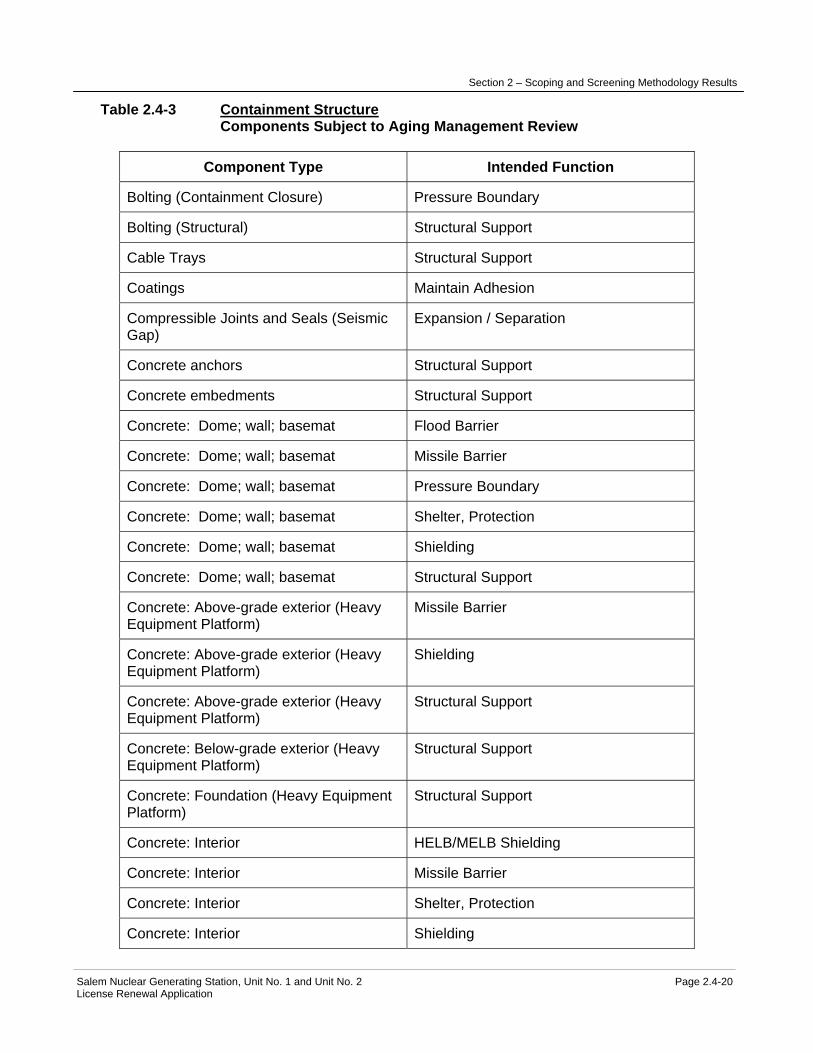
Section 2 – Scoping and Screening Methodology Results
Salem Nuclear Generating Station, Unit No. 1 and Unit No. 2 Page 2.4-20 License Renewal Application
Table 2.4-3 Containment Structure Components Subject to Aging Management Review
Component Type Intended Function
Bolting (Containment Closure) Pressure Boundary
Bolting (Structural) Structural Support
Cable Trays Structural Support
Coatings Maintain Adhesion
Compressible Joints and Seals (Seismic Gap)
Expansion / Separation
Concrete anchors Structural Support
Concrete embedments Structural Support
Concrete: Dome; wall; basemat Flood Barrier
Concrete: Dome; wall; basemat Missile Barrier
Concrete: Dome; wall; basemat Pressure Boundary
Concrete: Dome; wall; basemat Shelter, Protection
Concrete: Dome; wall; basemat Shielding
Concrete: Dome; wall; basemat Structural Support
Concrete: Above-grade exterior (Heavy Equipment Platform)
Missile Barrier
Concrete: Above-grade exterior (Heavy Equipment Platform)
Shielding
Concrete: Above-grade exterior (Heavy Equipment Platform)
Structural Support
Concrete: Below-grade exterior (Heavy Equipment Platform)
Structural Support
Concrete: Foundation (Heavy Equipment Platform)
Structural Support
Concrete: Interior HELB/MELB Shielding
Concrete: Interior Missile Barrier
Concrete: Interior Shelter, Protection
Concrete: Interior Shielding
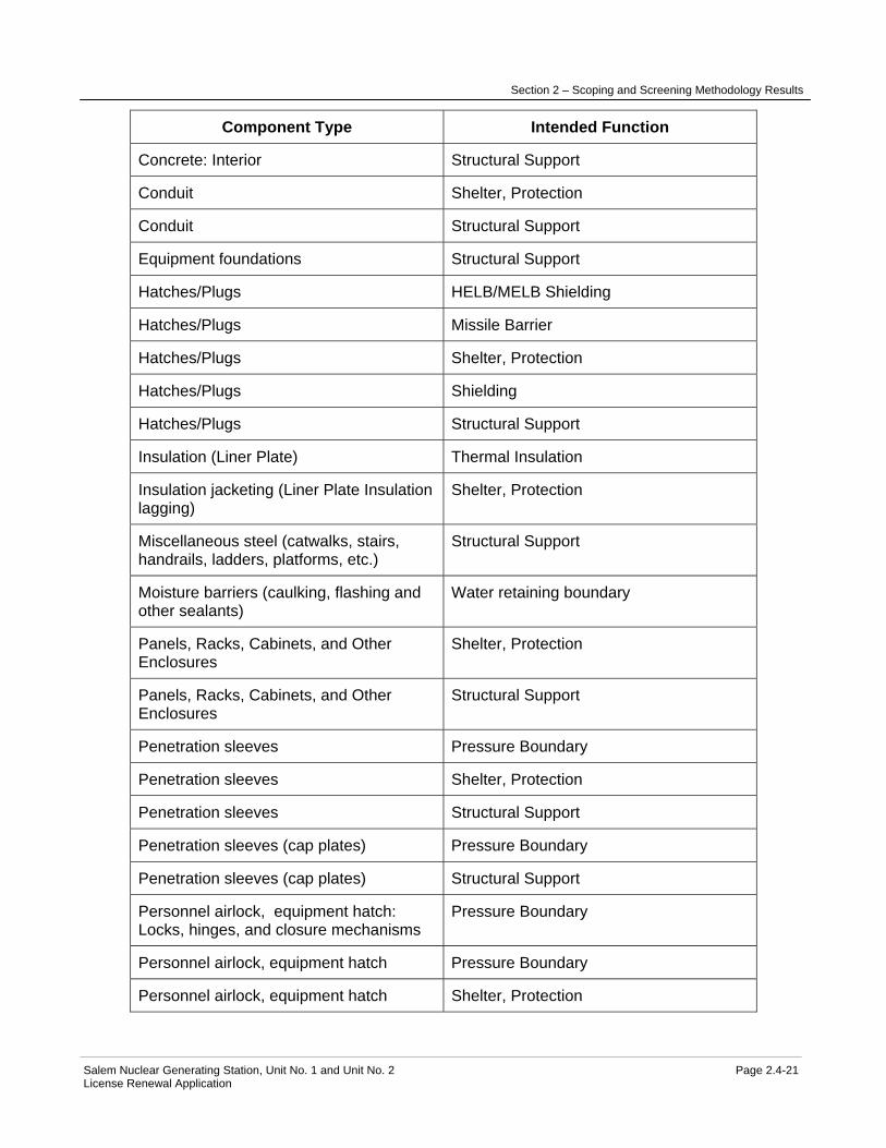
Section 2 – Scoping and Screening Methodology Results
Salem Nuclear Generating Station, Unit No. 1 and Unit No. 2 Page 2.4-21 License Renewal Application
Component Type Intended Function
Concrete: Interior Structural Support
Conduit Shelter, Protection
Conduit Structural Support
Equipment foundations Structural Support
Hatches/Plugs HELB/MELB Shielding
Hatches/Plugs Missile Barrier
Hatches/Plugs Shelter, Protection
Hatches/Plugs Shielding
Hatches/Plugs Structural Support
Insulation (Liner Plate) Thermal Insulation
Insulation jacketing (Liner Plate Insulation lagging)
Shelter, Protection
Miscellaneous steel (catwalks, stairs, handrails, ladders, platforms, etc.)
Structural Support
Moisture barriers (caulking, flashing and other sealants)
Water retaining boundary
Panels, Racks, Cabinets, and Other Enclosures
Shelter, Protection
Panels, Racks, Cabinets, and Other Enclosures
Structural Support
Penetration sleeves Pressure Boundary
Penetration sleeves Shelter, Protection
Penetration sleeves Structural Support
Penetration sleeves (cap plates) Pressure Boundary
Penetration sleeves (cap plates) Structural Support
Personnel airlock, equipment hatch: Locks, hinges, and closure mechanisms
Pressure Boundary
Personnel airlock, equipment hatch Pressure Boundary
Personnel airlock, equipment hatch Shelter, Protection

Section 2 – Scoping and Screening Methodology Results
Salem Nuclear Generating Station, Unit No. 1 and Unit No. 2 Page 2.4-22 License Renewal Application
Component Type Intended Function
Piles (heavy equipment platform foundation)
Structural Support
Pipe Whip Restraints, and Jet Impingement Shields
HELB/MELB Shielding
Pipe Whip Restraints, and Jet Impingement Shields
Pipe Whip Restraint
Seals, and gaskets Pressure Boundary
Steel Components: All structural steel Shielding
Steel Components: All structural steel Structural Support
Steel Components: Reactor cavity liner, Fuel Transfer Canal liner
Water retaining boundary
Steel Components: Sump Liner Water retaining boundary
Steel Components: Sump Screen Filter
Steel Components: Trench cover Filter
Steel elements: Liner; Liner anchors; Integral attachments
Pressure Boundary
Steel elements: Liner; Liner anchors; Integral attachments
Structural Support
Steel elements: Liner; Liner anchors; Integral attachments
Water retaining boundary
Transfer Tube: Bellows (excludes containment penetration bellows)
Water retaining boundary
Tube Track Structural Support The aging management review results for these components are provided in: Table 3.5.2-3 Containment Structure Summary of Aging Management Evaluation
Section 2 – Scoping and Screening Methodology Results
Salem Nuclear Generating Station, Unit No. 1 and Unit No. 2 Page 2.4-23 License Renewal Application
2.4.4 Fire Pump House
Structure Purpose The Fire Pump House is a single story above grade steel frame and masonry block structure, approximately 42 feet by 63 feet in plan. The building is located north of the Unit 2 Turbine Building in the yard, separated from safety-related systems, structures, and components (SSCs) such that its failure would not impact a safety-related function. The exterior walls are constructed of concrete masonry block. The interior of the building has been partitioned with concrete masonry block walls that separate the fresh water pump room from the fire pump room. The building foundation consists of a reinforced concrete slab on piles. The roof is constructed of precast concrete hollow core roof slabs supported on structural steel framing. The roof slabs are protected with 1 inch of insulation and built-up roofing material. The purpose of the Fire Pump House is to provide structural support, shelter and protection for Fire Protection System, Fresh Water System and supporting systems and components. Major components housed in the building include the diesel driven fire pumps, and jockey pumps, associated piping and piping components, controls and instrumentation, and electrical panels and enclosures; as well as, fresh water pumps, fresh water chlorination tanks and associated fresh water piping and piping components, controls and instrumentation, and electrical panels and enclosures. Included in the boundary of the Fire Pump House and determined to be in scope for license renewal are reinforced concrete foundation slab, foundation piles, concrete masonry block walls, structural steel framing, roof precast concrete, built up roofing, doors, penetration sleeves, penetration seals, conduit, cable trays, cabinets, enclosures, racks, frames and panels for electrical equipment and instrumentation, and anchorage for diesel driven fire pumps and for the jockey pumps. Refer to the "Components Subject to Aging Management Review" table below for a complete list of components included in the boundary of the Fire Pump House. Included in the boundary of the Fire Pump House and determined not in scope for license renewal are the platforms, ladders, stairs, and anchorage for fresh water pumps and for the fresh water chlorination tank and associated fresh water equipment anchorage. These components are provided to facilitate maintenance activities, to provide access to the equipment, or to support equipment associated with fresh water. They do not perform a license renewal intended function and their failure will not prevent satisfactory accomplishment of a safety-related function. Not included in the boundary of the Fire Pump House are component supports and fire barriers, as well as the adjacent water storage tank foundations. Component Supports are identified and separately evaluated in the Component Supports Commodity Group section. Fire barriers are identified and evaluated with the Fire Protection System. The adjacent water storage tank foundations are separately evaluated with Yard Structures For more detailed information, see UFSAR Section 9.5.1.7.
Section 2 – Scoping and Screening Methodology Results
Salem Nuclear Generating Station, Unit No. 1 and Unit No. 2 Page 2.4-24 License Renewal Application
Reason for Scope Determination The Fire Pump House is not in scope under 10 CFR 54.4(a)(1) because no portion of the structure is safety-related or relied upon to remain functional during and following design basis events. The Fire Pump House is not in scope under 10 CFR 54.4(a)(2) because failure of nonsafety-related portions of the structure would not prevent satisfactory accomplishment of function(s) identified for 10 CFR 54.4(a)(1). The Fire Pump House is in scope under 10 CFR 54.4(a)(3) because it provides physical support, shelter and protection for systems, structures and components (SSCs) relied upon in safety analyses or plant evaluations to perform a function that demonstrates compliance with the Commission's regulation for Fire Protection (10 CFR 50.48). The structure is not relied upon in any safety analyses or plant evaluations to perform a function that demonstrates compliance with the Commission's regulations for Environmental Qualification (10 CFR 50.49), Pressurized Thermal Shock (10 CFR 50.61), Anticipated Transients Without Scram (10 CFR 50.62), or Station Blackout (10 CFR 50.63). System Intended Functions 1. Provides physical support, shelter, and protection for systems, structures, and components relied upon in safety analyses or plant evaluations to perform a function that demonstrates compliance with the Commission's regulations for Fire Protection (10 CFR 50.48). 10 CFR 54.4(a)(3) UFSAR References 9.5.1.7 License Renewal Boundary Drawings LR-204802
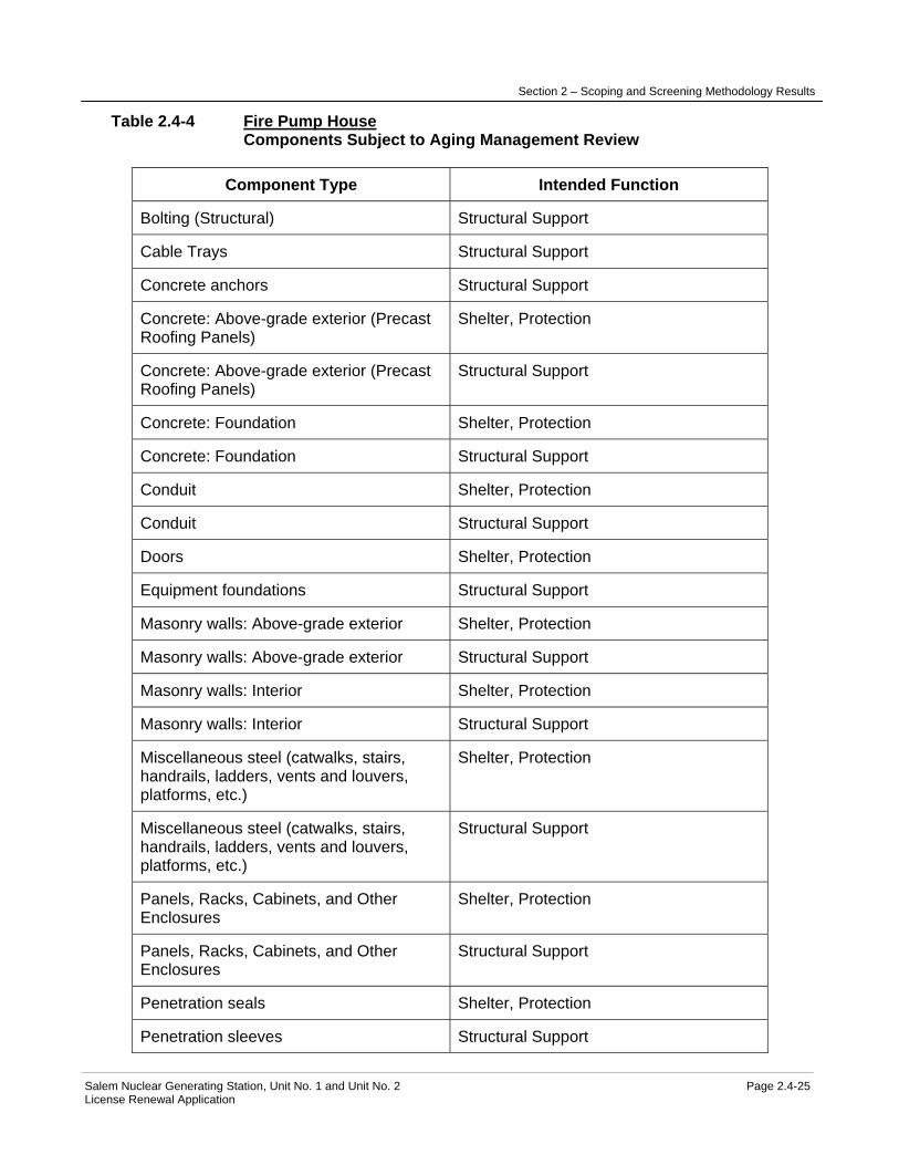
Section 2 – Scoping and Screening Methodology Results
Salem Nuclear Generating Station, Unit No. 1 and Unit No. 2 Page 2.4-25 License Renewal Application
Table 2.4-4 Fire Pump House Components Subject to Aging Management Review
Component Type Intended Function
Bolting (Structural) Structural Support
Cable Trays Structural Support
Concrete anchors Structural Support
Concrete: Above-grade exterior (Precast Roofing Panels)
Shelter, Protection
Concrete: Above-grade exterior (Precast Roofing Panels)
Structural Support
Concrete: Foundation Shelter, Protection
Concrete: Foundation Structural Support
Conduit Shelter, Protection
Conduit Structural Support
Doors Shelter, Protection
Equipment foundations Structural Support
Masonry walls: Above-grade exterior Shelter, Protection
Masonry walls: Above-grade exterior Structural Support
Masonry walls: Interior Shelter, Protection
Masonry walls: Interior Structural Support
Miscellaneous steel (catwalks, stairs, handrails, ladders, vents and louvers, platforms, etc.)
Shelter, Protection
Miscellaneous steel (catwalks, stairs, handrails, ladders, vents and louvers, platforms, etc.)
Structural Support
Panels, Racks, Cabinets, and Other Enclosures
Shelter, Protection
Panels, Racks, Cabinets, and Other Enclosures
Structural Support
Penetration seals Shelter, Protection
Penetration sleeves Structural Support

Section 2 – Scoping and Screening Methodology Results
Salem Nuclear Generating Station, Unit No. 1 and Unit No. 2 Page 2.4-26 License Renewal Application
Component Type Intended Function
Piles Structural Support
Roofing membrane Shelter, Protection
Seals, gaskets, and moisture barriers (caulking, flashing and other sealants)
Shelter, Protection
Steel components: All structural steel Structural Support
Tube Track Structural Support The aging management review results for these components are provided in: Table 3.5.2-4 Fire Pump House Summary of Aging Management Evaluation

Section 2 – Scoping and Screening Methodology Results
Salem Nuclear Generating Station, Unit No. 1 and Unit No. 2 Page 2.4-27 License Renewal Application
2.4.5 Fuel Handling Building
Structure Purpose The Fuel Handling Building is comprised of two separate fuel handling buildings, one for Salem Generating Station (SGS) Unit 1 and a second for Unit 2. Each building is constructed of reinforced concrete and located adjacent to, and to the west of its respective containment structure. The buildings are mirror images of each other reflected about the east-west SGS centerline. The roof of each building is a reinforced concrete slab supported on structural steel and sealed with waterproofing membrane. The building foundation consists of reinforced concrete mat placed on lean concrete that bears on the Vincentown Formation. The buildings are separated from the abutting Auxiliary Building by a seismic gap. The buildings are classified Category I (seismic) structures, designed to maintain their structural integrity during and following postulated design basis accidents and extreme environmental conditions. Each building contains the spent fuel storage pool, new fuel storage pit, fuel transfer pool, a decontamination pit, a sump room, and compartments that house spent fuel pool cooling equipment and supporting systems. The grade level of the buildings (elevation 100') includes a truck bay for shipping and receiving fuel and other materials. The fuel handling crane and the cask handling crane for each building facilitate transport of fuel and other materials inside the buildings. The spent fuel storage pool is approximately 37' x 28'-6" x 41' deep. It is constructed of reinforced concrete, and lined with stainless steel plate. The pool is designed for underwater storage of spent fuel assemblies after their removal from the reactor. SGS Technical Specifications require at least 23' of water be maintained over the top of irradiated fuel assemblies seated in the spent fuel storage pool racks. The fuel transfer pool is approximately 12' x 28'-6" x 45'-6" deep. This reinforced concrete pool is also lined with stainless steel plate. The pool is an intermediate handling area adjacent to the spent fuel storage pool and connected to the refueling canal inside the containment structure by a 20" diameter fuel transfer tube. The transfer tube serves as the passageway for fuel transfer operation between the fuel handling building and intake canal inside the containment structure. The fuel transfer pool can be isolated from the spent fuel storage pool and drained by using a fuel pool gate for maintenance of the fuel handling system. The gate seal consists of short lived inflatable seals supplied with air by the Compressed Air System. The design of the spent fuel storage pool and the fuel transfer pool includes a leak chase system that collects potential leakage through cracks in the seam welds of the stainless steel liners. The leak chase system consists of stainless steel channels embedded in the slabs and in the walls of the two pools. The design is such that any leakage collected in the channels is directed and discharged through 17 drain lines into the sump room trench outside the spent fuel pool in the fuel handling building. The purpose of the Fuel Handling Building is to provide structural support, shelter and protection to systems, structures, and components (SSCs) housed within it during normal plant operation, and during and following postulated design basis accidents and extreme environmental conditions. This function is provided to the Fuel Handling and Fuel Storage System, Spent Fuel Pool Cooling System, Fuel Handling Building Heating and Ventilation System, Compressed Air System, and their supporting systems. The building design features

Section 2 – Scoping and Screening Methodology Results
Salem Nuclear Generating Station, Unit No. 1 and Unit No. 2 Page 2.4-28 License Renewal Application
provide an essentially leak tight boundary to support the Fuel Handling Building Heating and Ventilation System in maintaining the building at a slight negative pressure and prevent the undue release of radioactivity to the public. The spent fuel storage pool of the Fuel Handling Building provides for onsite storage of irradiated fuel assemblies in the spent fuel storage racks until they are removed for offsite storage or reprocessing. The fuel transfer pool serves to facilitate the fuel transfer operation between the Fuel Handling Building and the Containment Structure. The fuel transfer pool is also used to prepare the spent fuel cask for shipment. The spent fuel storage pool and the fuel transfer pool contain borated water inventory to maintain adequate cooling of the spent fuel assemblies. The water inventory in combination with the building design features provide radiological protection and keep radiation doses below limits specified in 10 CFR 20. The new fuel storage pit provides for dry storage of new fuel received onsite until it is transferred to the spent fuel storage pool in preparation for refueling. The decontamination pit provides for decontamination of spent fuel shipping casks prior to their loading on the trucks for shipment offsite. Included in the boundary of the Fuel Handling Building are reinforced concrete elements of the building, cable trays, concrete embedments, compressible joints and seals, conduit, doors, expansion joints, instrumentation racks, frames, enclosures, miscellaneous steel, structural bolting, penetration sleeves, penetration seals, roofing membrane, spent fuel gates and inflatable seals, and steel components, including liners and the leak chase system. Also included in the boundary of this structure are the transfer tube expansion bellows (penetration bellows) connected to the fuel handling building wall penetration sleeves (both inside and outside of the building exterior wall). Assessment of the Fuel Handling Building boundary concluded that the building is in scope of license renewal in its entirety with the exception of the spent fuel pool gates and spent fuel pool gates inflatable seals. The spent fuel pool gates and inflatable seals are not used and are tagged out of service, but may be used to facilitate maintenance of the fuel handling system. The spent fuel pool gates and their inflatable seals are not required for any intended function. Refer to the "Components Subject to Aging Management Review" table below for a complete list of components in the boundary of the Fuel Handling Building. Not included in the boundary of the Fuel Handling Building are the fuel storage racks, fuel transfer tubes, fuel handling cranes, and the cask handling cranes. The fuel storage racks, fuel transfer tubes, and the fuel handling cranes are separately evaluated with the Fuel Handling and Fuel Storage System. The cask handling cranes are evaluated with Cranes and Hoists. Also not included in the boundary of the Fuel Handling Building are the fuel transfer tube expansion bellows connected to the containment and reactor cavity walls, component supports, and fire barriers. The expansion bellows are separately evaluated with the Containment Structure, while the component supports are separately evaluated with Component Supports Commodity Group and the fire barriers are evaluated with the Fire Protection System. For more detailed information, see UFSAR sections 1.3.1, 3.0, 9.1, 12.1 and 15.4 Reason for Scope Determination The Fuel Handling Building meets 10 CFR 54.4(a)(1) because it is a safety-related structure that is relied on to remain functional during and following design basis events. It meets 10 CFR 54.4(a)(2) because the building provides physical support and shelter for nonsafety-

Section 2 – Scoping and Screening Methodology Results
Salem Nuclear Generating Station, Unit No. 1 and Unit No. 2 Page 2.4-29 License Renewal Application
related systems, structures, and components (SSCs) whose failure could prevent satisfactory accomplishment of function(s) identified for 10 CFR 54.4(a)(1). It also meets 10 CFR 54.4(a)(3) because it provides physical support, shelter and protection for systems, structures, and components (SSCs) relied upon in safety analyses or plant evaluations to perform a function that demonstrates compliance with the Commission's regulations for Fire Protection (10 CFR 50.48). The Fuel Handling Building is not relied upon in any safety analyses or plant evaluations to perform a function that demonstrates compliance with the Commission's regulations for Environmental Qualification (10 CFR 50.49), Pressurized Thermal Shock (10 CFR 50.61), Anticipated Transients Without Scram (10 CFR 50.62), or Station Blackout (10 CFR 50.63). System Intended Functions 1. Provides physical support, shelter, and protection for safety-related systems, structures, and components. 10 CFR 54.4(a)(1) 2. Controls the potential release of fission products to the external environment so that offsite consequences of design basis events are within acceptable limits. 10 CFR 54.4(a)(1) 3. Provides physical support, shelter, and protection for nonsafety-related systems, structures, and components whose failure could prevent satisfactory accomplishment of function(s) identified for 10 CFR 54.4(a)(1). 10 CFR 54.4(a)(2) 4. Provides physical support, shelter, and protection for systems, structures, and components relied upon in safety analyses or plant evaluations to perform a function that demonstrates compliance with the Commission's regulations for Fire Protection (10 CFR 50.48). 10 CFR 54.4(a)(3) UFSAR References 1.3.1 3.0 9.1 12.1 15.4 License Renewal Boundary Drawings LR-204802

Section 2 – Scoping and Screening Methodology Results
Salem Nuclear Generating Station, Unit No. 1 and Unit No. 2 Page 2.4-30 License Renewal Application
Table 2.4-5 Fuel Handling Building Components Subject to Aging Management Review
Component Type Intended Function
Bolting (Structural) Structural Support
Cable Trays Structural Support
Compressible Joints and Seals Expansion / Separation
Concrete Curb Direct Flow
Concrete embedments Structural Support
Concrete embedments Water retaining boundary
Concrete: Above-grade exterior Flood Barrier
Concrete: Above-grade exterior Missile Barrier
Concrete: Above-grade exterior Shelter, Protection
Concrete: Above-grade exterior Structural Support
Concrete: Below-grade exterior Flood Barrier
Concrete: Below-grade exterior Shelter, Protection
Concrete: Below-grade exterior Structural Support
Concrete: Foundation Flood Barrier
Concrete: Foundation Shelter, Protection
Concrete: Foundation Structural Support
Concrete: Interior Flood Barrier
Concrete: Interior Missile Barrier
Concrete: Interior Shelter, Protection
Concrete: Interior Structural Support
Concrete: Interior (Spent fuel storage pool, Transfer pool)
Structural Support
Concrete: Interior (Trench) Direct Flow
Conduit Shelter, Protection
Conduit Structural Support
Doors Flood Barrier

Section 2 – Scoping and Screening Methodology Results
Salem Nuclear Generating Station, Unit No. 1 and Unit No. 2 Page 2.4-31 License Renewal Application
Component Type Intended Function
Doors Pressure Boundary
Doors Shelter, Protection
Equipment foundations Structural Support
Expansion Joint Shelter, Protection
Miscellaneous steel (catwalks, stairs, handrails, ladders, platforms, etc.)
Structural Support
Panels, Racks, Cabinets, and Other Enclosures
Shelter, Protection
Panels, Racks, Cabinets, and Other Enclosures
Structural Support
Penetration bellows (2 bellows for Transfer tube; excluding containment penetration bellows)
Expansion / Separation
Penetration bellows (2 bellows for Transfer tube; excluding containment penetration bellows)
Shelter, Protection
Penetration bellows (2 bellows for Transfer tube; excluding containment penetration bellows)
Water retaining boundary
Penetration seals Flood Barrier
Penetration seals Pressure Boundary
Penetration sleeves Pressure Boundary
Penetration sleeves Shelter, Protection
Penetration sleeves Structural Support
Penetration sleeves Water retaining boundary
Roofing membrane Shelter, Protection
Steel components: All structural steel Structural Support
Steel components: Leak chase system Direct Flow
Steel components: Spent fuel storage pool liner, Transfer pool liner, sump liner
Water retaining boundary

Section 2 – Scoping and Screening Methodology Results
Salem Nuclear Generating Station, Unit No. 1 and Unit No. 2 Page 2.4-32 License Renewal Application
The aging management review results for these components are provided in: Table 3.5.2-5 Fuel Handling Building Summary of Aging Management Evaluation

Section 2 – Scoping and Screening Methodology Results
Salem Nuclear Generating Station, Unit No. 1 and Unit No. 2 Page 2.4-33 License Renewal Application
2.4.6 Office Buildings
Structure Purpose The Office Buildings consist of the controlled facilities building, the clean facilities building, and the administration building. Controlled facilities building: The controlled facilities building, also known as A building, is a multi-story structure approximately 102 by 82 feet in plan area. The building is located west of the Containment Structure and is adjacent to the safety-related refueling water storage tanks and auxiliary feedwater storage tanks. It is comprised of structural steel framing, un-reinforced masonry walls, reinforced concrete slabs, foundation mat, and built up roofing over concrete fill. The foundation mat is supported on steel pipe piles filled with concrete. The controlled facilities building is connected to the Auxiliary Building by a walkway/truck bay enclosure approximately 79 feet long and 15 feet wide. The enclosure is two stories high, with the truck bay on ground level and the walkway on the second level. The enclosure is comprised of structural steel braced framing, un-reinforced masonry walls, and built up roofing over concrete fill. Its foundation is a reinforced concrete slab supported partly by steel pipe piles filled with concrete and partly on compacted soil. The controlled facilities building is partitioned into office space, storage rooms, a machine shop, mechanical equipment room, welding equipment area, and facilities for personnel occupying the building. The controlled facilities building and the walkway/truck bay enclosure are nonsafety-related structures and were not designed to meet seismic category I structures requirements. The structures were evaluated in response to NRC I.E. Bulletin 80-11 for seismic interaction (seismic II/I) with the adjacent safety-related refueling water storage tanks and auxiliary feedwater storage tanks. As a result, the bracing system of the structures was modified to maintain the overall structural integrity during the postulated design basis seismic events. In addition a wire mesh net was installed on the sides adjacent to the safety related tanks to prevent failed masonry block from striking the safety-related tanks or their associated piping. The controlled facilities building and the walkway/truck bay enclosure perform intended functions and are in scope for license renewal. The structures are required to maintain their structural integrity during design basis seismic events to prevent a failure that would impact the safety-related tanks and associated piping. Clean facilities building: The clean facilities building, also known as B building, is a multi-story irregularly shaped structure, approximately 123 feet by 207 feet in plan area. The building is located southeast of the Containment Structure and is comprised of structural steel framing, masonry walls, reinforced concrete walls and slabs, metal siding, and built up roofing over concrete fill. The building foundation consists of reinforced concrete grade beams and slab that are supported on steel pipe piles filled with concrete or on compacted soil.
Section 2 – Scoping and Screening Methodology Results
Salem Nuclear Generating Station, Unit No. 1 and Unit No. 2 Page 2.4-34 License Renewal Application
The clean facilities building includes the safety parameter display system (SPDS) battery room. The room is located outside the building and adjacent to its north wall. It is constructed with structural steel, reinforced masonry walls, and metal deck roof with rigid insulation and roofing membrane. Foundation for the room consists of reinforced concrete slab on grade. The clean facilities building is connected to the Unit 1 turbine building by a walkway enclosure approximately 92 feet long and 9 feet wide. The enclosure is comprised of structural steel, metal siding, metal roofing, and reinforced concrete foundation slab on grade. The clean facilities building contains the onsite technical support center (TSC) facility, which is comprised of the TSC, SPDS computer room, technical document (TDR) area, and the TSC mechanical equipment room. The rest of the building is partitioned into office space, storage rooms, a machine shop that is serviced with an overhead crane, mechanical equipment room, and facilities for personnel occupying the building. The clean facilities building is not a safety-related structure. It is separated from safety-related systems, structures, and components such that its failure will not impact a safety-related function. Portions of the building and the SPDS battery room house nonsafety-related equipment and electrical commodities that are credited in plant analyses for Anticipated Transients Without Scram (ATWS). These portions of the building perform an intended function and are in scope for license renewal. Administration building: The administration building is a two-story precast concrete commercial office building approximately 196 by 66 feet in plan area at grade level and 86 by 71 feet plan area at the second level. The building is located east of the Containment Structure and adjacent to the east wall of the Turbine Building. It is comprised of precast reinforced concrete walls, beams, and Twin-Tee beams, precast panels, glass, and built up roofing over concrete fill. The building foundation consists of a reinforced concrete slab supported on steel pipe piles filled with concrete. The administration building is partitioned into office space, storage rooms, chemistry laboratory and shop, mechanical equipment room, conference rooms, and facilities for personnel occupying the building. The building is classified as a nonsafety-related structure and its failure will not impact a safety-related function. The purpose of the Office Buildings is to provide physical support, shelter, and protection for nonsafety-related systems, structures, and components. The buildings also provide shelter and facilities for site management, engineering, chemistry, maintenance, and other site support personnel. Included the boundary of the Office Buildings are components that make up the controlled facilities building, clean facilities building, and the administration building. The controlled facilities building is required to maintain its structural integrity during the design basis seismic events to prevent impact on the safety-related tanks and piping. Building components that perform this function or provide shelter and protection against weather are in the scope of license renewal. These include structural steel, bolting, concrete embedments, concrete anchors, reinforced concrete, foundations, piles, roofing membrane, wire mesh net, exterior masonry walls, exterior doors, penetration sleeves, and seals.
Section 2 – Scoping and Screening Methodology Results
Salem Nuclear Generating Station, Unit No. 1 and Unit No. 2 Page 2.4-35 License Renewal Application
The clean facilities building provides structural support, shelter, and protection for nonsafety-related components and electrical commodities credited for ATWS. Components of the building that perform this function are in the scope of license renewal. These include structural steel, masonry walls, panels, racks, and other enclosures, reinforced concrete, foundations, concrete embedments, concrete anchors, conduits, cable trays, piles, penetration sleeves and seals, exterior doors, metal siding and metal decking, and roofing membrane. The administration building does not perform an intended function and the building components are not in the scope of license renewal. Refer to "Components Subject to Aging Management Review" table below for a complete list of components included in the boundary of the Office Buildings. Not included in the boundary of the Office Buildings are component supports and cranes and hoists. Component supports are separately evaluated with the Component Supports Commodity Group and cranes and hoists are evaluated with Cranes and Hoists license renewal system. For more detailed information, see UFSAR Sections 1.3.1, 3.3.2.3, and 11.4. Reason for Scope Determination The Office Buildings are not in scope under 10 CFR 54.4(a)(1) because no portions of the structures are safety-related or relied upon to remain functional during and following design basis events. They meet 10 CFR 54.4(a)(2) because the structures provide physical support, shelter, and protection for nonsafety-related systems, structures, and components (SSCs) whose failure could prevent satisfactory accomplishment of function(s) identified for 10 CFR 54.4(a)(1). They also meet 10 CFR 54.4(a)(3) because they provide physical support, shelter and protection for systems, structures, and components (SSCs) relied upon in safety analyses or plant evaluations to perform a function that demonstrates compliance with the Commission's regulations for Anticipated Transients Without Scram (10 CFR 50.62). The Office Buildings are not relied upon in any safety analyses or plant evaluations to perform a function that demonstrates compliance with the Commission's regulations for Fire Protection (10 CFR 50.48), Environmental Qualification (10 CFR 50.49), Pressurized Thermal Shock (10 CFR 50.61), or Station Blackout (10 CFR 50.63). System Intended Functions 1. Provides physical support, shelter, and protection for nonsafety-related systems, structures, and components (SSCs) whose failure could prevent satisfactory accomplishment of function's identified for 10 CFR 54.4 (a)(1). 10 CFR 54.4(a)(2) 2. Provides physical support, shelter, and protection for systems, structures, and components relied upon in safety analyses or plant evaluations to perform a function that demonstrates compliance with the Commission's regulations for Anticipated Transients Without Scram (10 CFR 50.62). 10 CFR 54.4(a)(3) UFSAR References 1.3.1 3.3.2.3 11.4

Section 2 – Scoping and Screening Methodology Results
Salem Nuclear Generating Station, Unit No. 1 and Unit No. 2 Page 2.4-36 License Renewal Application
License Renewal Boundary Drawings LR-204802

Section 2 – Scoping and Screening Methodology Results
Salem Nuclear Generating Station, Unit No. 1 and Unit No. 2 Page 2.4-37 License Renewal Application
Table 2.4-6 Office Buildings Components Subject to Aging Management Review
Component Type Intended Function
Bolting (Structural) Structural Support
Cable Trays Structural Support
Concrete Anchors Structural Support
Concrete Embedments Structural Support
Concrete: Above-grade exterior Shelter, Protection
Concrete: Above-grade exterior Structural Support
Concrete: Below-grade exterior Shelter, Protection
Concrete: Below-grade exterior Structural Support
Concrete: Foundation Shelter, Protection
Concrete: Foundation Structural Support
Concrete: Interior Shelter, Protection
Concrete: Interior Structural Support
Conduit Shelter, Protection
Conduit Structural Support
Doors Shelter, Protection
Masonry walls: Above-grade exterior Shelter, Protection
Masonry walls: Above-grade exterior Structural Support
Masonry walls: Interior Shelter, Protection
Masonry walls: Interior Structural Support
Metal components: Wire mesh net Shelter, Protection
Metal decking Shelter, Protection
Metal decking Structural Support
Metal siding Shelter, Protection
Panels, Racks, Cabinets, and Other Enclosures
Shelter, Protection

Section 2 – Scoping and Screening Methodology Results
Salem Nuclear Generating Station, Unit No. 1 and Unit No. 2 Page 2.4-38 License Renewal Application
Component Type Intended Function
Panels, Racks, Cabinets, and Other Enclosures
Structural Support
Penetration seals Shelter, Protection
Penetration sleeves Shelter, Protection
Penetration sleeves Structural Support
Piles Structural Support
Roofing membrane Shelter, Protection
Seals, gaskets, and moisture barriers (caulking, flashing and other sealants)
Shelter, Protection
Steel Components: All structural steel Structural Support The aging management review results for these components are provided in: Table 3.5.2-6 Office Buildings Summary of Aging Management Evaluation
Section 2 – Scoping and Screening Methodology Results
Salem Nuclear Generating Station, Unit No. 1 and Unit No. 2 Page 2.4-39 License Renewal Application
2.4.7 Penetration Areas
Structure Purpose The Penetration Areas consist of two reinforced concrete enclosed areas, the Salem Generating Station (SGS) Unit 1 south outer penetration area and the SGS Unit 2 north outer penetration area. The areas, or structures, are located at the exit of the Main Steam System, and the Main Condensate and Feedwater System piping from the containments en route to the Turbine Building. The roof of each structure is a reinforced concrete slab and its foundation consists of a reinforced concrete mat placed on lean concrete that bears on Vincentown Formation or on compacted soil. The structures are classified Category I (seismic) structures, designed to maintain their structural integrity during and following postulated design basis accidents and extreme environmental conditions. A seismic gap separates the structures from the containment buildings to prevent their interaction during the postulated design basis seismic events. The design of the structures includes blowout panels to maintain the internal pressure within acceptable limits following the postulated rupture of the main steam and the feedwater systems piping inside the areas. The purpose of the Penetration Areas is to support and protect safety-related Main Steam, and Main Condensate and Feedwater System piping and components and their supporting mechanical and electrical systems. The structures also provide radiation shielding and protection for the Containment Structure penetrations. Included in the boundary of the Penetration Areas are reinforced concrete components that make up the structures. Other components in the boundary of the Penetration Areas include bird screens, bolting, blowout panels, cable trays, conduit, concrete embedments, concrete anchors, compressible joints and seals, doors, hatch plugs, miscellaneous steel, pipe whip restraints, panels, racks and other enclosures, penetration sleeves, penetration seals, and tube track. The Penetration Areas perform intended functions delineated in 10 CFR 54.4 and are in the scope of license renewal in their entirety; except for ladders and handrails supported on the outside of the structures. The ladders and the handrails provide personnel access to the roof. They do not perform an intended function and their failure would not impact a safety-related function. Refer to the "Components Subject to Aging Management Review" table below for a complete list of components included in the boundary of the Penetration Areas. Not included in the boundary of the Penetration Areas are inner penetration areas, component supports, main steam and feedwater systems piping and components, electrical systems and commodities, piping and component insulation. Inner penetration areas are separately evaluated with the Auxiliary Building. The component supports are separately evaluated with the Component Supports Commodity Group. Similarly main steam and feedwater systems piping and components are evaluated with the Main Steam System, and Main Condensate and Feedwater System. Electrical systems and components housed inside the structures are separately evaluated with electrical systems and commodities. Piping and component insulation is separately evaluated with the Piping and Component Insulation Commodity Group. For more detailed information, see UFSAR Sections 2.4, 3.4.3, and 3.6.5

Section 2 – Scoping and Screening Methodology Results
Salem Nuclear Generating Station, Unit No. 1 and Unit No. 2 Page 2.4-40 License Renewal Application
Reason for Scope Determination The Penetration Areas meet 10 CFR 54.4(a)(1) because they are safety-related structures that are relied on to remain functional during and following design basis events. The areas meet 10 CFR 54.4(a)(2) because the structures provide physical support, shelter and protection for nonsafety-related systems, structures, and components (SSCs) whose failure could prevent satisfactory accomplishment of function(s) identified for 10 CFR 54.4(a)(1). They also meet 10 CFR 54.4(a)(3) because they provide physical support, shelter and protection for systems, structures, and components (SSCs) relied upon in safety analyses or plant evaluations to perform a function that demonstrates compliance with the Commission's regulations for Environmental Qualification (10 CFR 50.49), Anticipated Transients Without Scram (10 CFR 50.62), and Station Blackout (10 CFR 50.63). The Penetration Areas are not relied upon in safety analyses or plant evaluations to perform a function that demonstrates compliance with the Commission's regulations for Fire Protection (10 CFR 50.48), or Pressurized Thermal Shock (10 CFR 50.61). System Intended Functions 1. Provide physical support, shelter, and protection for safety-related systems, structures, and components. 10 CFR 54.4(a)(1) 2. Provide physical support, shelter, and protection for nonsafety-related systems, structures, and components whose failure could prevent satisfactory accomplishment of function(s) identified for 10 CFR 54.4(a)(1). 10 CFR 54.4(a)(2) 3. Provide physical support, shelter, and protection for systems, structures, and components relied upon in safety analyses or plant evaluations to perform a function that demonstrates compliance with the Commission's regulations for Environmental Qualification (10 CFR 50.49). 10 CFR 54.4(a)(3) 4. Provide physical support, shelter, and protection for systems, structures, and components relied upon in safety analyses or plant evaluations to perform a function that demonstrates compliance with the Commission's regulations for Anticipated Transients Without Scram (10 CFR 50.62). 10 CFR 54.4(a)(3) 5. Provide physical support, shelter, and protection for systems, structures, and components relied upon in safety analyses or plant evaluations to perform a function that demonstrates compliance with the Commission's regulations for Station Blackout (10 CFR 50.63). 10 CFR 54.4(a)(3) UFSAR References 2.4 3.4.3 3.6.5 10.3.3.2 License Renewal Boundary Drawings LR-204802

Section 2 – Scoping and Screening Methodology Results
Salem Nuclear Generating Station, Unit No. 1 and Unit No. 2 Page 2.4-41 License Renewal Application
Table 2.4-7 Penetration Areas Components Subject to Aging Management Review
Component Type Intended Function
Blowout Panel Pressure Relief
Blowout Panel Shelter, Protection
Bolting (Structural) Structural Support
Cable Trays Structural Support
Compressible Joints and Seals (Seismic Gap)
Expansion / Separation
Compressible Joints and Seals (Seismic Gap)
Shelter, Protection
Concrete Curbs Direct Flow
Concrete anchors Structural Support
Concrete embedments Structural Support
Concrete: Above-grade exterior Flood Barrier
Concrete: Above-grade exterior Missile Barrier
Concrete: Above-grade exterior Shelter, Protection
Concrete: Above-grade exterior Structural Support
Concrete: Below-grade exterior Flood Barrier
Concrete: Below-grade exterior Missile Barrier
Concrete: Below-grade exterior Shelter, Protection
Concrete: Below-grade exterior Structural Support
Concrete: Foundation Flood Barrier
Concrete: Foundation Shelter, Protection
Concrete: Foundation Structural Support
Concrete: Interior Flood Barrier
Concrete: Interior HELB/MELB Shielding
Concrete: Interior Missile Barrier
Concrete: Interior Shelter, Protection
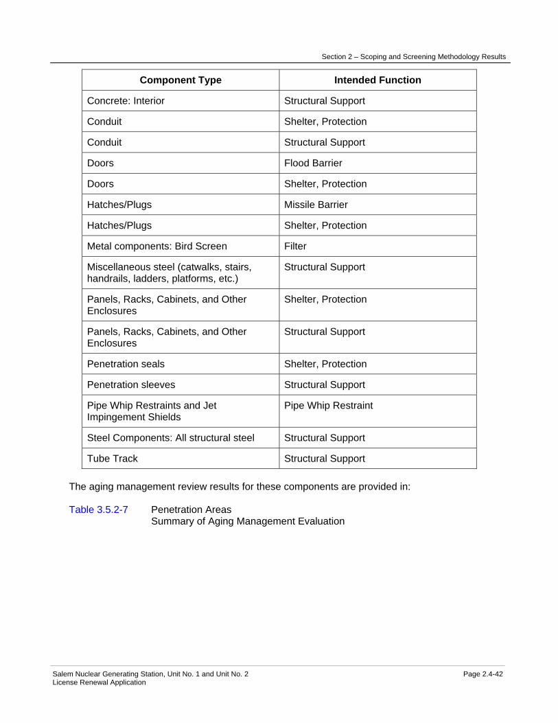
Section 2 – Scoping and Screening Methodology Results
Salem Nuclear Generating Station, Unit No. 1 and Unit No. 2 Page 2.4-42 License Renewal Application
Component Type Intended Function
Concrete: Interior Structural Support
Conduit Shelter, Protection
Conduit Structural Support
Doors Flood Barrier
Doors Shelter, Protection
Hatches/Plugs Missile Barrier
Hatches/Plugs Shelter, Protection
Metal components: Bird Screen Filter
Miscellaneous steel (catwalks, stairs, handrails, ladders, platforms, etc.)
Structural Support
Panels, Racks, Cabinets, and Other Enclosures
Shelter, Protection
Panels, Racks, Cabinets, and Other Enclosures
Structural Support
Penetration seals Shelter, Protection
Penetration sleeves Structural Support
Pipe Whip Restraints and Jet Impingement Shields
Pipe Whip Restraint
Steel Components: All structural steel Structural Support
Tube Track Structural Support The aging management review results for these components are provided in: Table 3.5.2-7 Penetration Areas Summary of Aging Management Evaluation

Section 2 – Scoping and Screening Methodology Results
Salem Nuclear Generating Station, Unit No. 1 and Unit No. 2 Page 2.4-43 License Renewal Application
2.4.8 Pipe Tunnel
Structure Purpose The Pipe Tunnel is a two-cell reinforced concrete rectangular box section located west of the containment buildings, and adjacent to the west wall of the Auxiliary Building. The tunnel is approximately 269 feet 8 inches long, 49 feet wide and 17 feet 8 inches high. Its bottom slab is 4 feet 6 inches thick, supported on compacted backfill brought up from the top of the lean concrete fill. The roof slab, also 4 feet 6 inches thick, extends above the grade level by approximately 1 foot and provides structural support for the auxiliary feed storage tanks, the refueling water storage tanks, and the primary water storage tanks. The Pipe Tunnel is classified as a Category I (Seismic) structure. The purpose of the Pipe Tunnel is to provide structural support for SGS Unit 1 and Unit 2 refueling water storage tanks, auxiliary feed tanks, and primary water storage tanks. The tunnel also provides structural support, shelter, and protection for the Service Water System piping and piping components, and supporting electrical systems. Included in boundary of the Pipe Tunnel are reinforced concrete elements of the tunnel, bolting, cable trays, concrete anchors, concrete embedments, conduit, panels, racks, cabinets and other enclosures, manhole covers, penetration sleeves, seals and gaskets, and penetration seals. The Pipe Tunnel performs intended functions delineated in 10 CFR 54.4 and is in scope for license renewal. Refer to the "Components Subject to Aging Management Review" table below for a complete list of components included in the boundary of the Pipe Tunnel. Not included in the boundary of the Pipe Tunnel are mechanical systems and components, including piping, piping components, valves, and tanks. These components are separately evaluated with Service Water System, Radwaste System, Auxiliary Feedwater System, Safety Injection System or Chemical and Volume Control System as appropriate. Also not included in the boundary of the Pipe Tunnel are electrical commodities, and component supports. Electrical commodities are evaluated with Electrical Commodities and component supports are separately evaluated with the Component Supports Commodity Group. For more detailed information, see UFSAR Sections 3.8.5, 6.3.2, and 9.2.1. Reason for Scope Determination The Pipe Tunnel meets 10 CFR 54.4(a)(1) because it is a safety-related structure that is relied on to remain functional during and following design basis events. It meets 10 CFR 54.4(a)(2) because the structure provides physical support and shelter for nonsafety-related systems, structures, and components (SSCs) whose failure could prevent satisfactory accomplishment of function(s) identified for 10 CFR 54.4(a)(1). The Pipe Tunnel is in scope under 10 CFR 54.4(a)(3) because it provides physical support, shelter, and protection for systems, structures, and components (SSCs) relied upon in safety analyses or plant evaluations to perform a function that demonstrates compliance with the Commission's regulations for Station Blackout (10 CFR 50.63). The structure is not relied upon in any safety analyses or plant evaluations to perform a function that demonstrates compliance with the Commission's regulations for Fire Protection (10 CFR 50.48), Environmental Qualification (10 CFR 50.49), Pressurized Thermal Shock (10 CFR 50.61), or Anticipated Transients Without Scram (10 CFR 50.62).

Section 2 – Scoping and Screening Methodology Results
Salem Nuclear Generating Station, Unit No. 1 and Unit No. 2 Page 2.4-44 License Renewal Application
System Intended Functions 1. Provides physical support, shelter, and protection for safety-related systems, structures, and components. 10 CFR 54.4(a)(1) 2. Provides physical support, shelter, and protection for nonsafety-related systems, structures, and components whose failure could prevent satisfactory accomplishment of function(s) identified for 10 CFR 54.4(a)(1). 10 CFR 54.4(a)(2) 3. Provides physical support, shelter, and protection for systems, structures, and components relied upon in safety analyses or plant evaluations to perform a function that demonstrates compliance with the Commission's regulations for Station Blackout (10 CFR 50.63). 10 CFR 54.4(a)(3) UFSAR References 3.8.5.1 6.3.2.11 9.2.1 License Renewal Boundary Drawings LR-204802
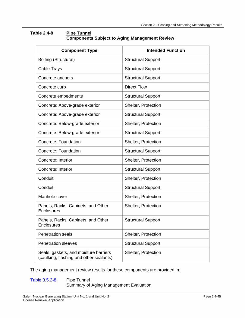
Section 2 – Scoping and Screening Methodology Results
Salem Nuclear Generating Station, Unit No. 1 and Unit No. 2 Page 2.4-45 License Renewal Application
Table 2.4-8 Pipe Tunnel Components Subject to Aging Management Review
Component Type Intended Function
Bolting (Structural) Structural Support
Cable Trays Structural Support
Concrete anchors Structural Support
Concrete curb Direct Flow
Concrete embedments Structural Support
Concrete: Above-grade exterior Shelter, Protection
Concrete: Above-grade exterior Structural Support
Concrete: Below-grade exterior Shelter, Protection
Concrete: Below-grade exterior Structural Support
Concrete: Foundation Shelter, Protection
Concrete: Foundation Structural Support
Concrete: Interior Shelter, Protection
Concrete: Interior Structural Support
Conduit Shelter, Protection
Conduit Structural Support
Manhole cover Shelter, Protection
Panels, Racks, Cabinets, and Other Enclosures
Shelter, Protection
Panels, Racks, Cabinets, and Other Enclosures
Structural Support
Penetration seals Shelter, Protection
Penetration sleeves Structural Support
Seals, gaskets, and moisture barriers (caulking, flashing and other sealants)
Shelter, Protection
The aging management review results for these components are provided in: Table 3.5.2-8 Pipe Tunnel Summary of Aging Management Evaluation

Section 2 – Scoping and Screening Methodology Results
Salem Nuclear Generating Station, Unit No. 1 and Unit No. 2 Page 2.4-46 License Renewal Application
2.4.9 Piping and Component Insulation Commodity Group
Structure Purpose The Piping and Component Insulation Commodity Group is comprised of pre-fabricated blankets, modules, or panels engineered as integrated assemblies to fit the surface to be insulated and to fit easily against the piping and components. The insulation includes metallic and nonmetallic materials. Metallic insulation, or reflective mirror insulation, is fabricated from stainless steel material. This insulation is used on the reactor coolant system (RCS) components and portions of the steam generator blowdown piping and steam generator feedwater piping. Nonmetallic insulation includes totally encapsulated or semi-encapsulated ceramic fiber insulation "cera-blanket", fibrous insulation, including Nukon insulation, calcium silicate, and Min "K", which is a high efficiency powder-like insulation totally enclosed in stainless steel. Anti-sweat insulation consists of fiberglass material jacketed with fiberglass fabric impregnated with silicone, or flexible closed cell rubber material. The use of flexible closed cell rubber insulation has been discontinued because of its leachable chloride content, which promotes stress corrosion cracking on stainless steel. The fiberglass and calcium silicate insulation is covered with stainless steel or aluminum protective jackets held in-place by stainless steel straps or clips. In some cases, stainless steel wire mesh is used to cover the insulation instead of the protective jacket. The Piping and Component Insulation Commodity Group is not classified as a safety-related commodity. The purpose of piping and component insulation is to improve thermal efficiency, minimize heat loads on the HVAC systems, provide for personnel protection, or prevent freezing of heat traced piping, and protect against sweating of cold piping and components. Insulation of piping within containment penetrations in conjunction with the penetration cooling system limits the concrete temperature adjacent to the embedded sleeve within the allowable limit. Insulation located in areas with safety-related equipment is designed to maintain its structural integrity during the postulated design basis seismic events and accidents. Portions of piping and component insulation inside the Containment Structure are required to maintain their integrity to prevent exceeding the analyzed debris limit for the containment sump screens. Included in the boundary of the Piping and Component Insulation Commodity Group is insulation for all piping and components inside safety-related structures, and insulation for in scope piping and components located in the outdoor environment. The insulation and insulation jacketing (includes wire mesh, straps, clips) perform an intended function and are in scope for license renewal under 10 CFR 54.4 (a)(2). Refer to "Components Subject to Aging Management Review" table below for a complete list of components included in the boundary of Piping and Component Insulation Commodity Group. Not included the boundary of the Piping and Component Insulation Commodity Group is insulation for the containment liner plate. This containment liner plate insulation is separately evaluated with the Containment Structure. For more detailed information, see UFSAR Sections 5.2.3, 5.4.2, and 6.3.2.

Section 2 – Scoping and Screening Methodology Results
Salem Nuclear Generating Station, Unit No. 1 and Unit No. 2 Page 2.4-47 License Renewal Application
Reason for Scope Determination The Piping and Component Insulation Commodity Group is not in scope under 10 CFR54.4(a)(1) because no portions of the insulation are safety-related or relied on to remain functional during and following design basis events. The Piping and Component Insulation Commodity Group is in scope under 10 CFR 54.4(a)(2) because failure of the nonsafety-related insulation could prevent satisfactory accomplishment of function(s) identified for 10 CFR 54.4(a)(1). The insulation is not in scope under 10 CFR 54.4(a)(3) because it is not relied upon in any safety analyses or plant evaluations to perform a function that demonstrates compliance with the Commission's regulations for Fire Protection (10 CFR 50.48), Environmental Qualification (10 CFR 50.49), Pressurized Thermal Shock (10 CFR 50.61), Anticipated Transients Without Scram (10 CFR 50.62), or Station Blackout (10 CFR 50.63). System Intended Functions 1. Resists nonsafety-related SSC failure that could prevent satisfactory accomplishment of a safety-related function. The insulation is required to maintain its integrity during design basis seismic events to prevent interaction with safety-related SSCs. Portions of piping and component insulation inside the Containment Structure is required to maintain its integrity to prevent exceeding the analyzed debris limit for the containment sump screens. Hot piping and component insulation protects nearby safety-related SSCs from overheating. Outdoor piping and component insulation in conjunction with heat tracing provides freeze protection for in scope piping and components. (10 CFR 54.4(a)(2) UFSAR References 5.2.3 5.4.2 6.3.2 License Renewal Boundary Drawings None
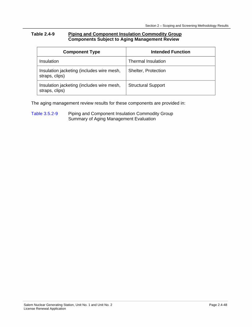
Section 2 – Scoping and Screening Methodology Results
Salem Nuclear Generating Station, Unit No. 1 and Unit No. 2 Page 2.4-48 License Renewal Application
Table 2.4-9 Piping and Component Insulation Commodity Group Components Subject to Aging Management Review
Component Type Intended Function
Insulation Thermal Insulation
Insulation jacketing (includes wire mesh, straps, clips)
Shelter, Protection
Insulation jacketing (includes wire mesh, straps, clips)
Structural Support
The aging management review results for these components are provided in: Table 3.5.2-9 Piping and Component Insulation Commodity Group Summary of Aging Management Evaluation

Section 2 – Scoping and Screening Methodology Results
Salem Nuclear Generating Station, Unit No. 1 and Unit No. 2 Page 2.4-49 License Renewal Application
2.4.10 SBO Compressor Building
Structure Purpose The SBO Compressor Building is a concrete block structure located northeast of the Salem Generating Station (SGS) Unit 2 containment structure. The building is a single story, approximately 28' x 15' in plan dimensions. The building foundation consists of a reinforced concrete slab bearing on compacted fill. Its roof is composed of a precast prestressed concrete hollow core slab topped with 2" of concrete reinforced with welded wire fabric. The SBO Compressor Building is a nonsafety-related structure, designed to commercial grade standards. The structure is separated from safety-related systems, structures, and components (SSCs) such that its failure would not impact a safety-related function. The purpose of the SBO Compressor Building is to provide physical support, shelter, and protection for the SBO diesel driven air compressor and its auxiliary systems. The compressor is credited for providing control air during SBO event. Major components housed inside the building include the SBO diesel driven air compressor, regenerative air dryer, after-cooler, transformers, distribution panel, disconnect switch, and piping and piping components. Included in the boundary of the SBO Compressor Building are reinforced concrete and prestressed concrete components, concrete block, doors, concrete anchors, concrete embedments, and miscellaneous steel. The SBO Compressor Building is in scope of license renewal in its entirety. Refer to the "Components Subject to Aging Management Review" table below for a complete list of components included in the boundary of the SBO Compressor Building. Not included in the boundary of the SBO Compressor Building is the SBO diesel driven air compressor and components for its auxiliary systems, component supports. The SBO Diesel driven air compressor and components for its auxiliary systems are separately evaluated with the Compressed Air System. Component supports are separately evaluated with the Component Supports Commodity Group. For more detail information, refer to UFSAR Section 9.3.1. Reason for Scope Determination The SBO Compressor Building is not in scope under 10 CFR 54.4(a)(1) because no portions of the structure are safety-related or relied on to remain functional during and following design basis events. It is not in scope under 10 CFR 54.4(a)(2) because failure of nonsafety-related portions of the structure will not prevent satisfactory accomplishment of function(s) identified for 10 CFR 54.4(a)(1). The SBO Compressor Building meets 10 CFR 54.4(a)(3) because it provides physical support, shelter and protection for systems, structures and components (SSCs) relied upon in the safety analyses or plant evaluations to perform a function that demonstrates compliance with the Commission's regulations for Station Blackout (10 CFR 50.63). It is not relied upon in any safety analyses or plant evaluations to perform a function that demonstrates compliance with the Commission's regulations for Fire Protection (10 CFR 50.48), Environmental Qualification (10 CFR 50.49), Pressurized Thermal Shock (10 CFR 50.61), or Anticipated Transients Without Scram (10 CFR 50.62).
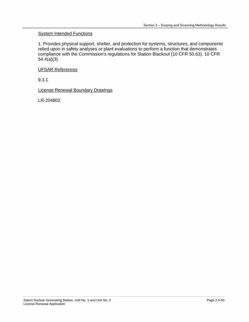
Section 2 – Scoping and Screening Methodology Results
Salem Nuclear Generating Station, Unit No. 1 and Unit No. 2 Page 2.4-50 License Renewal Application
System Intended Functions 1. Provides physical support, shelter, and protection for systems, structures, and components relied upon in safety analyses or plant evaluations to perform a function that demonstrates compliance with the Commission's regulations for Station Blackout (10 CFR 50.63). 10 CFR 54.4(a)(3). UFSAR References 9.3.1 License Renewal Boundary Drawings LR-204802

Section 2 – Scoping and Screening Methodology Results
Salem Nuclear Generating Station, Unit No. 1 and Unit No. 2 Page 2.4-51 License Renewal Application
Table 2.4-10 SBO Compressor Building Components Subject to Aging Management Review
Component Type Intended Function
Bolting (Structural) Structural Support
Concrete anchors Structural Support
Concrete embedments Structural Support
Concrete: Above-grade exterior Shelter, Protection
Concrete: Above-grade exterior Structural Support
Concrete: Foundation Shelter, Protection
Concrete: Foundation Structural Support
Concrete: Interior (includes precast prestressed concrete roof slab)
Shelter, Protection
Concrete: Interior (includes precast prestressed concrete roof slab)
Structural Support
Doors Shelter, Protection
Masonry walls: Above-grade exterior Shelter, Protection
Masonry walls: Above-grade exterior Structural Support
Metal components: All structural members
Structural Support
Miscellaneous steel (catwalks, stairs, handrails, ladders, vents and louvers, platforms, etc.)
Shelter, Protection
The aging management review results for these components are provided in: Table 3.5.2-10 SBO Compressor Building Summary of Aging Management Evaluation
Section 2 – Scoping and Screening Methodology Results
Salem Nuclear Generating Station, Unit No. 1 and Unit No. 2 Page 2.4-52 License Renewal Application
2.4.11 Service Building
Structure Purpose The Service Building is a common Salem Generating Station (SGS) Unit 1 and Unit 2 multi-story structure; approximately 219 by 47 feet in plan area, located between the Auxiliary Building and the Turbine Building. Above ground level, the building is steel framed structure, enclosed with precast reinforced concrete panels on two sides and masonry walls on the third or the Turbine Building side. The building is enclosed on the fourth side partly by precast reinforced concrete panels and partly by the eastern wall of the Auxiliary Building. The below ground level portions of the building are enclosed with reinforced concrete walls and a basement slab founded on the top of circulating water outlet piping foundation. This foundation consists of reinforced concrete supported on steel piles filled with concrete. The roof is a reinforced concrete slab covered by rigid insulation and roofing membrane. The roof supports two small steel penthouses enclosed with precast concrete panels, and building air intake and exhaust louvers. The penthouses shelter stairways that provide access to the roof. The building interior structures are comprised of reinforced concrete components, masonry walls, gypsum board walls, removable office partitions, and structural steel. The Service Building is partitioned into office areas, training areas, main access control into the radiological area, maintenance shops, and facilities for personnel occupying the building. Components inside the building are nonsafety-related except for two Auxiliary Feedwater System isolation valves within trenches in the basement floor of the building. The valves are supported from the Category I Auxiliary Building wall and protected by a structural steel barrier from debris falling in the Service Building. The structural steel protective barrier is also supported from the Auxiliary Building wall. The building internal structures include cable vaults and cable shafts for routing electrical cables between Auxiliary Building and Turbine Building. The cables are nonsafety-related except for instrument cables for Reactor Protection System (RPS) sensors in the Turbine Building. The RPS is a failsafe design, with other diverse safety-related reactor scram signals such that no single failure or credible natural disaster can prevent a reactor scram. Some nonsafety-related cables are for systems credited for Anticipated Transients Without Scram (ATWS). The Service Building is nonsafety-related, classified as Category III (seismic) structure. Category III structures are designed for loadings commonly used in the design of conventional power plants and constructed to commercial standards. The building is braced to withstand tornado wind and seismic forces such that it will not collapse on the adjacent Auxiliary Building. A seismic gap is formed between the Service Building and the adjacent Auxiliary Building to prevent their interaction during the design basis seismic events. The purpose of the Service Building is to house equipment, tools, and personnel required for supporting operation of SGS Unit 1 and Unit 2. It provides office space and facilities for plant support personnel, training areas, and maintenance shops. The building also serves as the primary point of access to and exit from the controlled area. The building also provides shelter and protection for components classified as safety-related, components credited for ATWS, and fire protection system piping and components. The Service Building is required to maintain its structural integrity during the postulated design basis events to prevent impacting Category I structures.

Section 2 – Scoping and Screening Methodology Results
Salem Nuclear Generating Station, Unit No. 1 and Unit No. 2 Page 2.4-53 License Renewal Application
Included in the boundary of the Service Building are structural elements of the building comprised of reinforced concrete, structural steel, and masonry block. Other components in the boundary of the building include precast panels, metal decking, cable trays, concrete anchors, concrete embedments, doors, compressible joints and seals, conduit, racks, frames, enclosures, miscellaneous steel, bolting, penetration sleeves, penetration seals, roofing membrane, trenches, and tube track. Evaluation of the Service Building boundary concluded that structural elements of the building required for the building to maintain its structural integrity during design basis events are in scope for license renewal. These include structural steel framing, bolting, concrete embedments, load bearing walls, slabs, and the foundation slab including piles. Precast panels, hatch plugs, doors, miscellaneous steel, seals for the roof and precast panels, the masonry wall adjacent to the Turbine Building, and roofing membrane provide shelter and are in the scope of license renewal. Cable trays, concrete anchors, conduits, trenches and the protective steel barriers for the Auxiliary Feedwater System valves, masonry walls for the cable vaults and cable shafts are in the scope of license renewal because they provide structural support, shelter, and protection for safety-related components and for systems and components credited for ATWS and fire protection. The remaining components included in the boundary of the Service Building do not perform an intended function and are not in the scope of license renewal. Refer to the "Components Subject to Aging Management Review" table below for a complete list of components included in the boundary of the Service Building. Not included in the boundary of the Service Building are component supports, seismic gap material, cranes and hoists, elevator, and piping and component insulation. The component supports are separately evaluated with the Component Supports Commodity Group, and the seismic gap is evaluated with the Auxiliary Building. Cranes and hoists are evaluated with Cranes and Hoists, the elevator is evaluated with Elevators and Manlifts, and piping and component insulation is evaluated with Piping and Component Insulation Commodity Group. For more detailed information, see UFSAR Sections 1.3.1, 3.7.2, and 3.3.2. Reason for Scope Determination The Service Building is not in scope under 10 CFR 54.4(a)(1) because no portions of the structure are safety-related or relied upon to remain functional during and following design basis events. The Service Building is in scope under 10 CFR 54.4(a)(2) because failure of the structure could prevent satisfactory accomplishment of function(s) identified for 10 CFR 54.4(a)(1). The Service Building meets 10 CFR 54.4(a)(3) because it provides physical support, shelter and protection for systems, structures, and components (SCCs) relied upon in safety analyses or plant evaluations to perform a function that demonstrates compliance with the Commission's regulations for Fire Protection (10 CFR 50.48), and Anticipated Transients Without Scram (10 CFR 50.62). The building is not relied upon in any safety analyses or plant evaluations to perform a function that demonstrates compliance with the Commission's regulations for Environmental Qualification (10 CFR 50.49), Pressurized Thermal Shock (10 CFR 50.61), or Station Blackout (10 CFR 50.63). System Intended Functions 1. Provides physical support, shelter, and protection for nonsafety-related systems, structures, and components (SSCs) whose failure could prevent satisfactory accomplishment of function(s) identified for 10 CFR 54.4 (a)(1). 10 CFR 54.4(a)(2)

Section 2 – Scoping and Screening Methodology Results
Salem Nuclear Generating Station, Unit No. 1 and Unit No. 2 Page 2.4-54 License Renewal Application
2. Provides physical support, shelter, and protection for systems, structures, and components relied upon in safety analyses or plant evaluations to perform a function that demonstrates compliance with the Commission's regulations for Fire Protection (10 CFR 50.48). 10 CFR 54.4(a)(3) 3. Provides physical support, shelter, and protection for systems, structures, and components relied upon in safety analyses or plant evaluations to perform a function that demonstrates compliance with the Commission's regulations for Anticipated Transients Without Scram (10 CFR 50.62). 10 CFR 54.4(a)(3) UFSAR References 1.3.1 3.3.2.3 3.7.2 9.4.1.2 10.4 12.3.3 License Renewal Boundary Drawings LR-204802

Section 2 – Scoping and Screening Methodology Results
Salem Nuclear Generating Station, Unit No. 1 and Unit No. 2 Page 2.4-55 License Renewal Application
Table 2.4-11 Service Building Components Subject to Aging Management Review
Component Type Intended Function
Bolting (Structural) Structural Support
Cable Trays Structural Support
Concrete Anchors Structural Support
Concrete Embedments Structural Support
Concrete: Above-grade exterior Shelter, Protection
Concrete: Above-grade exterior Structural Support
Concrete: Below-grade exterior Shelter, Protection
Concrete: Below-grade exterior Structural Support
Concrete: Foundation Shelter, Protection
Concrete: Foundation Structural Support
Concrete: Interior Shelter, Protection
Concrete: Interior Structural Support
Conduit Shelter, Protection
Conduit Structural Support
Doors Shelter, Protection
Hatches/Plugs Shelter, Protection
Masonry walls: Interior Shelter, Protection
Masonry walls: Interior Structural Support
Miscellaneous steel (louvers, curbs, rain shields, hood)
Shelter, Protection
Panels, Racks, Cabinets, and Other Enclosures
Shelter, Protection
Panels, Racks, Cabinets, and Other Enclosures
Structural Support
Piles Structural Support
Precast Panels Shelter, Protection
Roofing membrane Shelter, Protection
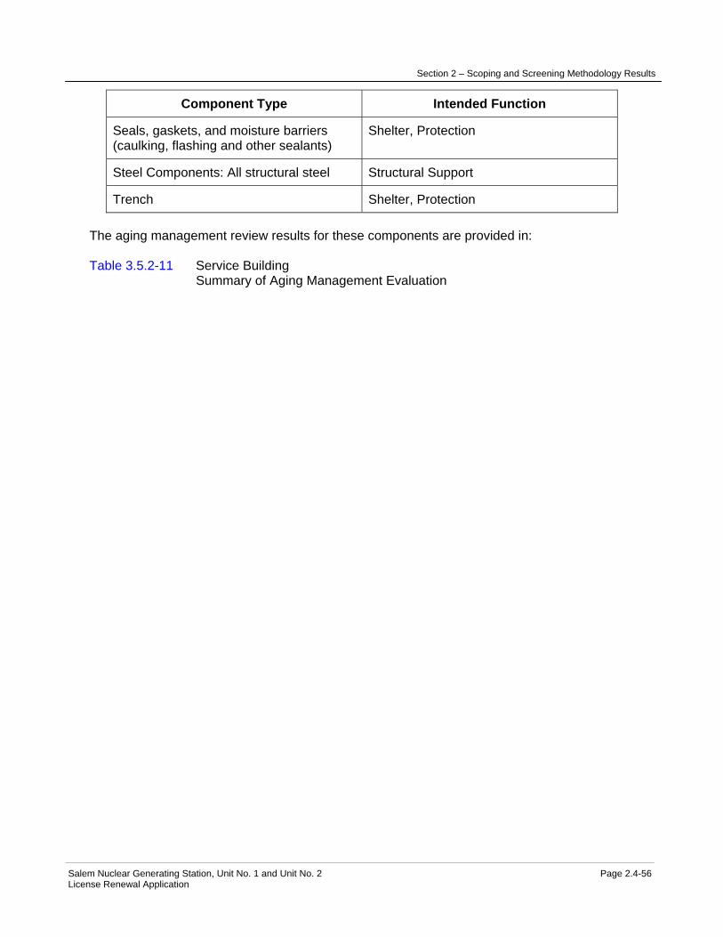
Section 2 – Scoping and Screening Methodology Results
Salem Nuclear Generating Station, Unit No. 1 and Unit No. 2 Page 2.4-56 License Renewal Application
Component Type Intended Function
Seals, gaskets, and moisture barriers (caulking, flashing and other sealants)
Shelter, Protection
Steel Components: All structural steel Structural Support
Trench Shelter, Protection The aging management review results for these components are provided in: Table 3.5.2-11 Service Building Summary of Aging Management Evaluation
Section 2 – Scoping and Screening Methodology Results
Salem Nuclear Generating Station, Unit No. 1 and Unit No. 2 Page 2.4-57 License Renewal Application
2.4.12 Service Water Accumulator Enclosures
Structure Purpose The Service Water Accumulator Enclosures consist of two enclosures that house Salem Generating Station (SGS) Unit 1 and Unit 2 Service Water System accumulator tanks. The enclosures are located west of the Containment Structure, one adjacent to the north wall of the Unit 1 fuel handling building, and the other is adjacent to the south wall of the Unit 2 fuel handling building. Each enclosure is comprised of structural steel frames, metal siding, prefabricated roof panels, and reinforced concrete slab on grade. The steel frames are supported on reinforced concrete footings founded on soil, and from reinforced concrete walls of the Fuel Handling Building and the Auxiliary Building. The structural steel frames and plate, the reinforced concrete footings, and other components that provide structural support or shelter and protection for the accumulator tanks are classified Category I (Seismic) structures. The remaining portions of the enclosures are nonsafety-related designed to maintain their structural integrity during design basis events (Seismic II/I) to prevent interaction with the safety-related Service Water System components. The purpose of the Service Water Accumulator Enclosures is to provide structural support, shelter and protection for safety-related Service Water System accumulator tanks and associated Service Water System piping and piping components. The enclosures also house nonsafety-related systems, structures, and components whose failure could impact a safety-related function. Included in boundary of the Service Water Accumulator Enclosures are structural steel frames of the enclosure, steel plate, reinforced concrete floor slab and footings, bolting, cable trays, concrete anchors, conduits, metal siding, prefabricated roof panels, panels, racks, cabinets and other enclosures, compressible joints and seals, doors, miscellaneous steel, and tube track. The structural steel and reinforced concrete components, concrete anchors, metal siding and prefabricated roof panels, bolting, doors, seals, and miscellaneous steel, perform intended functions delineated in 10 CFR 54.4(a) and are in scope for license renewal. Other components inside the enclosures do not perform an intended function and are not in the scope of license renewal. Refer to the " Components Subject to Aging Management Review" table below for a complete list of components included in the boundary of the Service Water Accumulator Enclosures. Not included in the boundary of the Service Water Accumulator Enclosures are the Service Water System accumulator tanks and component supports. The accumulator tanks are separately evaluated with Service Water System and the component supports are separately evaluated with the Component Supports Commodity Group. Reason for Scope Determination The Service Water Accumulator Enclosures meet 10 CFR 54.4(a)(1) because they are safety-related structures that are relied on to remain functional during and following design basis events. They meet 10 CFR 54.4(a)(2) because the structures provide physical support and shelter for nonsafety-related systems, structures, and components (SSCs) whose failure could prevent satisfactory accomplishment of function(s) identified for 10 CFR 54.4(a)(1). The

Section 2 – Scoping and Screening Methodology Results
Salem Nuclear Generating Station, Unit No. 1 and Unit No. 2 Page 2.4-58 License Renewal Application
Service Water Accumulator Enclosures are not in scope under 10 CFR 54.4(a)(3) because they are not relied upon in any safety analyses or plant evaluations to perform a function that demonstrates compliance with the Commission's regulations for Fire Protection (10 CFR 50.48), Environmental Qualification (10 CFR 50.49), Pressurized Thermal Shock (10 CFR 50.61), Anticipated Transients Without Scram (10 CFR 50.62), or Station Blackout (10 CFR 50.63). System Intended Functions 1. Provides physical support, shelter, and protection for safety-related systems, structures, and components. 10 CFR 54.4(a)(1) 2. Provides physical support, shelter, and protection for nonsafety-related systems, structures, and components whose failure could prevent satisfactory accomplishment of function(s) identified for 10 CFR 54.4(a)(1). 10 CFR 54.4(a)(2) UFSAR References 9.2.1 License Renewal Boundary Drawings LR-204802

Section 2 – Scoping and Screening Methodology Results
Salem Nuclear Generating Station, Unit No. 1 and Unit No. 2 Page 2.4-59 License Renewal Application
Table 2.4-12 Service Water Accumulator Enclosures Components Subject to Aging Management Review
Component Type Intended Function
Bolting (Structural) Structural Support
Concrete Anchors Structural Support
Concrete: Above-grade exterior Shelter, Protection
Concrete: Above-grade exterior Structural Support
Concrete: Below-grade exterior Shelter, Protection
Concrete: Below-grade exterior Structural Support
Concrete: Foundation Structural Support
Doors Shelter, Protection
Metal siding Shelter, Protection
Miscellaneous steel (catwalks, handrails, ladders, platforms, etc.)
Structural Support
Seals, gaskets, and moisture barriers (caulking, flashing and other sealants)
Shelter, Protection
Steel Components: All structural steel Missile Barrier
Steel Components: All structural steel Structural Support
Steel Components: Pre-fabricated roof panels
Shelter, Protection
The aging management review results for these components are provided in: Table 3.5.2-12 Service Water Accumulator Enclosures Summary of Aging Management Evaluation

Section 2 – Scoping and Screening Methodology Results
Salem Nuclear Generating Station, Unit No. 1 and Unit No. 2 Page 2.4-60 License Renewal Application
2.4.13 Service Water Intake
Structure Purpose The Service Water lntake structure is a reinforced concrete structure located along the western shoreline of the facility and on the eastern bank of the Delaware River. The Service Water Intake structure is a multi-story structure; approximately 100 x 140 feet in plan area, comprised of reinforced concrete walls, slabs, foundation mat, and miscellaneous structural steel. The reinforced concrete foundation mat is supported on a lean concrete fill bearing directly on the Vincentown Formation. The roof is a reinforced concrete slab. During the construction of the foundation, sheet piling and cofferdams were utilized. The cofferdams are on the river bank either side of the Service Water Intake structure and are a part of the Shoreline Dike feature. The Service Water lntake structure is designed to protect the enclosed portion of the Service Water System and related vital components under postulated environmental and design basis accident loadings, and is designated safety-related and Category I (seismic). There is an added fiberglass windbreak and traveling screen enclosure on the roof above the traveling screen upper housing which is supported by a structural steel frame. There is also an air intake penthouse (louvered) and raised steel support structure mounted on the roof. The Service Water lntake structure, which houses twelve (12) vertical turbine-type Service Water pumps, is comprised of four (4) pump rooms, each with its own control room. The six service water pumps for each unit are arranged in groups of three pumps each, and each group of pumps for one unit is installed in alternate watertight compartments inside the intake structure. The compartments alternate by unit such that a compartment for Unit 1 pumps is immediately adjacent to a compartment for Unit 2 pumps, so that the compartments alternate according to the plant unit. Each service water pump is recessed approximately 50 feet from the river face of the intake. Based on the above, damage or blockage to two adjacent compartments of the intake can occur without cutting off the supply of service water to either unit. The Service Water Intake structure and Service Water System are designed to provide a reliable source of cooling water from the Delaware River. The Atlantic Ocean is the ultimate heat sink as described in the UFSAR. The front portion of the Service Water Intake structure is divided into twelve (12) intake cells. Automatic traveling water screens are provided at each intake cell and combined with the full-depth trash racks to filter debris from the incoming flow. A mobile mechanical trash rake unit is provided to maintain unobstructed passageways at the trash racks. Two-foot-wide fish-escape passages are located abreast of the traveling water screens to minimize the entrapment of fish in the individual intake cells. The portion of the Service Water Intake structure enclosing the pumps, motors, and vital switch gear is watertight. The Service Water Intake structure can also withstand static and dynamic storm effects. Each vertical, turbine type service water pump column bowl and suction bell is installed in an individual chamber which is open to the river. The chamber is isolated from the watertight compartments above where the pump discharge heads are bolted down to pads on a reinforced concrete floor slab. The joint between the pump discharge head and the pad is watertight to prevent leakage of water into the compartments. A sump pump is also provided in each compartment to remove any accumulated water in the event a minor leak should occur.

Section 2 – Scoping and Screening Methodology Results
Salem Nuclear Generating Station, Unit No. 1 and Unit No. 2 Page 2.4-61 License Renewal Application
Ice barriers are provided to protect the Service Water Intake structure. The ice barriers are constructed of steel shapes and treated wood and are designed such that surface ice jams will not damage the Service Water Intake structure. The barriers enable the intake components to operate normally without the effect of ice. The design of the ice barriers includes marine dock bumpers to protect the Service Water Intake structure. The purpose of the Service Water Intake structure is to support and protect the enclosed portion of the Service Water System and its related vital components under postulated environmental and design basis accident loading conditions and to provide access to a reliable source of cooling water for plant safe shutdown from the Delaware River. Major components housed inside the building include electrical switchgear, miscellaneous electrical equipment and components and their enclosures, instrumentation and their enclosures as applicable, trash racks, service water piping, service water pumps, and the traveling water screens. The Service Water Intake structure also houses or supports nonsafety-related equipment including cranes and hoists. Included in the boundary of the Service Water Intake structure and determined to be in scope for license renewal are reinforced concrete beams, slabs, walls, foundation, roof, doors, platforms, steel components, bolting, concrete anchors, concrete embedments, ladders, stairs, penetration sleeves, penetration seals, conduit, cable trays, panels, racks, cabinets and other enclosures, hatches/plugs, metal panels, ice barrier, marine dock bumpers, trash racks, traveling screen steel support structure, raised steel support structure for air intake penthouse, air intake penthouse, vortex suppressors, anchorage for service water pumps, and the steel frame for the windbreak and traveling screen enclosure on the roof over the upper traveling screen housing. Refer to the "Components Subject to Aging Management Review" table below for a complete list of components included in the boundary of the Service Water Intake structure. Included in the boundary of the Service Water Intake structure and determined not in scope for license renewal are the gates, stop logs, gate and stop log guides, the fiberglass panels for the windbreak and traveling screen enclosure on the roof and the trash cart. These components are provided to facilitate maintenance activities, or provide access to the equipment. They do not perform a license renewal intended function and their failure will not prevent satisfactory accomplishment of a safety-related function. Not included in the boundary of the Service Water Intake structure are cranes and hoists, cofferdams and shoreline dike, fire barriers, and components supports. Cranes and hoists are evaluated separately with the Cranes and Hoists system, fire barriers are evaluated separately with the Fire Protection System, and the component supports are evaluated with the Component Supports Commodity Group. Cofferdams and shoreline dike are evaluated separately with the license renewal Shoreline Protection and Dike structure. Components also not included in the boundary of the Service Water Intake structure are the mechanical components for the Service Water System, including the traveling water screens as well as the screen wash system, which are evaluated with the license renewal Service Water System. For more detailed information, see UFSAR Section 9.2 Reason for Scope Determination The Service Water Intake structure meets 10 CFR 54.4(a)(1) because it is a safety-related structure that is relied on to remain functional during and following design basis events. It

Section 2 – Scoping and Screening Methodology Results
Salem Nuclear Generating Station, Unit No. 1 and Unit No. 2 Page 2.4-62 License Renewal Application
meets 10 CFR 54.4(a)(2) because failure of nonsafety-related portions of the structure could prevent satisfactory accomplishment of function(s) identified for 10 CFR 54.4(a)(1). It also meets 10 CFR 54(a)(3) because it provides physical support, shelter and protection for systems, structures and components (SSCs) relied upon in safety analyses or plant evaluations to perform a function that demonstrates compliance with the Commission's regulations for Fire Protection (10 CFR 50.48) and Station Blackout (10 CFR 50.63). The Service Water Intake structure is not relied upon in any analyses or plant evaluations to perform a function that demonstrates compliance with the Commission's regulations for Environmental Qualification (10 CFR 50.49), Pressurized Thermal Shock (10 CFR 50.61), or Anticipated Transients Without Scram (10 CFR 50.62). System Intended Functions 1. Provides physical support, shelter, and protection for safety-related systems, structures, and components (SSCs) . 10 CFR 54.4(a)(1) 2. Provides physical support, shelter, and protection for nonsafety-related systems, structures, and components (SSCs) whose failure could prevent satisfactory accomplishment of function(s) identified for 10 CFR 54.4 (a)(1). 10 CFR 54.4(a)(2) 3. Provides a source of cooling water for plant safe shutdown. 10 CFR 54.4(a)(1) The Service Water Intake structure and Service Water System are designed to provide a reliable source of cooling water from the Delaware River. The Atlantic Ocean is the ultimate heat sink as described in the UFSAR. 4. Provides physical support, shelter, and protection for systems structures and components relied upon in safety analyses or plant evaluations to perform a function that demonstrates compliance with the Commission's regulations for Fire Protection (10 CFR 50.48). 10 CFR 54.4(a)(3) 5. Provides physical support, shelter, and protection for systems structures and components relied upon in safety analyses or plant evaluations to perform a function that demonstrates compliance with the Commission's regulations for Station Blackout (10 CFR 50.63). 10 CFR 54.4(a)(3) UFSAR References 2.4.1.1.2 3.2.1 9.2.1 License Renewal Boundary Drawings LR-204802

Section 2 – Scoping and Screening Methodology Results
Salem Nuclear Generating Station, Unit No. 1 and Unit No. 2 Page 2.4-63 License Renewal Application
Table 2.4-13 Service Water Intake Components Subject to Aging Management Review
Component Type Intended Function
Bolting (Structural) Structural Support
Cable Trays Structural Support
Concrete anchors Structural Support
Concrete embedments Structural Support
Concrete: Above-grade exterior Flood Barrier
Concrete: Above-grade exterior Missile Barrier
Concrete: Above-grade exterior Shelter, Protection
Concrete: Above-grade exterior Structural Support
Concrete: Below-grade exterior Flood Barrier
Concrete: Below-grade exterior Shelter, Protection
Concrete: Below-grade exterior Structural Support
Concrete: Foundation Flood Barrier
Concrete: Foundation Shelter, Protection
Concrete: Foundation Structural Support
Concrete: Interior Direct Flow
Concrete: Interior Flood Barrier
Concrete: Interior Shelter, Protection
Concrete: Interior Structural Support
Conduit Shelter, Protection
Conduit Structural Support
Doors Flood Barrier
Doors Shelter, Protection
Equipment foundations Structural Support
Hatches/Plugs Flood Barrier
Hatches/Plugs Shelter, Protection

Section 2 – Scoping and Screening Methodology Results
Salem Nuclear Generating Station, Unit No. 1 and Unit No. 2 Page 2.4-64 License Renewal Application
Component Type Intended Function
Ice Barrier, Marine Dock Bumper Shelter, Protection
Metal panels (Support Extension for Air Intake Penthouse)
Flood Barrier
Metal panels (Support Extension for Air Intake Penthouse)
Shelter, Protection
Metal panels (Support Extension for Air Intake Penthouse)
Structural Support
Miscellaneous steel (catwalks, stairs, handrails, ladders, vents and louvers, platforms, etc.)
Shelter, Protection
Miscellaneous steel (catwalks, stairs, handrails, ladders, vents and louvers, platforms, etc.)
Structural Support
Miscellaneous steel (vortex suppressors) Direct Flow
Panels, Racks, Cabinets, and Other Enclosures
Structural Support
Penetration seals Flood Barrier
Penetration sleeves Structural Support
Seals, gaskets, and moisture barriers (caulking, flashing and other sealants)(including at hatches)
Flood Barrier
Steel components: (Trash Racks) Filter
Steel components: All structural steel (Includes Windbreak steel on roof & Travelling Screen Support Structure)
Structural Support
The aging management review results for these components are provided in: Table 3.5.2-13 Service Water Intake Summary of Aging Management Evaluation

Section 2 – Scoping and Screening Methodology Results
Salem Nuclear Generating Station, Unit No. 1 and Unit No. 2 Page 2.4-65 License Renewal Application
2.4.14 Shoreline Protection and Dike
Structure Purpose The Shoreline Protection and Dike, which is also known as the "sea wall", "flood protection dike" or "dike", is a shoreline protective structural feature comprised primarily of rock, armor stone, steel sheet piles, cofferdams, intake structures, and concrete which is located along the Delaware River shoreline of Artificial Island. The original earthen Shoreline Protection and Dike south of the powerblock between the Salem Barge Slip and up to and including the Service Water Intake and cofferdams was replaced with rock fill and armor stone to limit wave run-up against Salem Generating Station (SGS) Unit 1 and Unit 2 Category I structures. This section of the Shoreline Protection and Dike is considered safety-related and Category I, except for the circulating water intake structure walls, which are nonsafety-related. The Shoreline Protection and Dike continues north of the Service Water Intake cofferdams and south of the barge slip; however, these portions are nonsafety-related existing earthen dikes with wood and steel sheet piles placed during island construction. The Shoreline Protection and Dike between the barge slip and Circulating Water Intake Structure has a top of dike elevation of 109.0 feet, and consists of a two layer 6-ton rock armor stone underlain by smaller size stone. A sheet pile cutoff wall was driven beneath the seaward edge of the rest of the dike and extended into the granular soils of the old river bottom. The Shoreline Protection and Dike between the Circulating Water Intake Structure and the Service Water Intake is at 109.0 feet and this dike consists of two layers of 3-ton rock armor stone. The purpose of the Shoreline Protection and Dike is to provide a flood protection barrier between the Delaware River and the plant site that limits wave run-up during design basis storm surge events to elevations on buildings sealed for external flooding. Included in the boundary of the Shoreline Protection and Dike are components of the Artificial Island dike within SGS Unit 1 and 2 and Hope Creek Generating Station site boundary. Components of the dike include the reinforced concrete outer walls of the circulating water intake structure, sheet piling, rock, armor stone, embankments, and cofferdams adjacent to the circulating water intake structure and the Service Water Intake buildings. That portion of the Shoreline Protection and Dike that extends along the shoreline from the Salem barge slip to the cofferdam north of the Service Water Intake performs a flood protection intended function and is in the scope of license renewal. The Shoreline Protection and Dike outside of this boundary is not credited for flood protection of SGS Units 1 and 2 and is not in the scope of license renewal. Refer to the "Components Subject to Aging Management Review" table below for a complete list of components included in the boundary of the Shoreline Protection and Dike. Not included in the boundary of the Shoreline Protection and Dike are the outer walls of the Service Water Intake structure, which are credited to limit wave run-up. The walls are separately evaluated with the Service Water Intake. For more detailed information, see UFSAR Sections 2.4.5.7 and 3.4.3.1.

Section 2 – Scoping and Screening Methodology Results
Salem Nuclear Generating Station, Unit No. 1 and Unit No. 2 Page 2.4-66 License Renewal Application
Reason for Scope Determination The Shoreline Protection and Dike meets 10 CFR 54.4(a)(1) because it is a safety-related structure that is relied upon to remain functional during and following design basis events. It meets 10 CFR 54.4(a)(2) because the structure provides flood protection for nonsafety-related systems, structures, and components (SSCs) whose failure could prevent satisfactory accomplishment of function(s) identified for 10 CFR 54.4(a)(1). The Shoreline Protection and Dike is not relied upon in any safety analyses or plant evaluations to perform a function that demonstrates compliance with the Commission's regulations for Fire Protection (10 CFR 50.48), Environmental Qualification (10 CFR 50.49), Pressurized Thermal Shock (10 CFR 50.61), Anticipated Transients without Scram (10 CFR 50.62), or Station Blackout (10 CFR 50.63). System Intended Functions 1. Provides flood protection for safety related systems, structures, and components (SSCs). 10 CFR 54.4 (a)(1) 2. Provides flood protection for nonsafety-related systems, structures, and components (SSCs) whose failure could prevent satisfactory accomplishment of function(s) identified for 10 CFR 54.4 (a)(1). 10 CFR 54.4(a)(2) UFSAR References 2.4.1.1 2.4.5 2.5.5 3.4.3.1 License Renewal Boundary Drawings LR-204802

Section 2 – Scoping and Screening Methodology Results
Salem Nuclear Generating Station, Unit No. 1 and Unit No. 2 Page 2.4-67 License Renewal Application
Table 2.4-14 Shoreline Protection and Dike Components Subject to Aging Management Review
Component Type Intended Function
Concrete: Above-grade exterior Flood Barrier
Concrete: Below-grade exterior Flood Barrier
Earthen water-control structures: Embankments (dikes)
Flood Barrier
Piles (Sheet Piles) Flood Barrier The aging management review results for these components are provided in: Table 3.5.2-14 Shoreline Protection and Dike Summary of Aging Management Evaluation

Section 2 – Scoping and Screening Methodology Results
Salem Nuclear Generating Station, Unit No. 1 and Unit No. 2 Page 2.4-68 License Renewal Application
2.4.15 Switchyard
Structure Purpose The Switchyard is located in a fenced area east of the Containment Structure and adjacent to the Turbine Building. Its foundation consists of a reinforced concrete slabs, beams, grade beams and walls, and box sections founded on steel piles that were driven down to the sound Vincentown Formation. The steel pipe piles are filled with concrete. The Switchyard design includes trenches, duct banks, and manholes for routing of electrical cable, oil retention sumps, and reinforced concrete skimming tanks. The Switchyard is a nonsafety-related, non-seismic structure. The purpose of the Switchyard is to provide physical support, shelter, and protection to the 13KV System and the Offsite-500KV System components and commodities. The Offsite-500KV System consists of three 500 kV transmission lines connected to a breaker-and-a-half design with four 500 kV-13 kV transformers. The Offsite-500KV System receives site generated power and transmits it over three transmission lines to the Public Service Electric & Gas electric transmission network. The systems are relied upon to provide offsite power during Station Blackout (SBO) event restoration. Included in the boundary of the Switchyard are reinforced concrete and steel components, which include steel piles, equipment foundations, transmission towers, duct banks, manholes, trenches, sumps, structural bolting, embedments, and concrete anchors. Components and structures that provide structural support, shelter, and protection to the 13KV System and the Offsite-500KV system are in the scope of license renewal. Other components and structures in the Switchyard do not perform an intended function and are not in the scope of license renewal. Refer to the "Components Subject to Aging Management Review" table below for a complete list of components in the boundary of the Switchyard. Not included in the boundary of the Switchyard are electrical components and commodities, and component supports. Electrical components and commodities are separately evaluated with the 13KV System and the Offsite-500KV System. Component supports are separately evaluated with the Component Supports Commodity Group. The skimming tanks are separately evaluated with the Yard Structures. For more detail information, refer to UFSAR Sections 1.3.8, and 8.2 Reason for Scope Determination The Switchyard is not in scope under 10 CFR 54.4(a)(1) because no portions of the structure are safety-related or relied on to remain functional during and following design basis events. It is not in scope under 10 CFR 54.4(a)(2) because failure of nonsafety-related portions of the structure will not prevent satisfactory accomplishment of function(s) identified for 10 CFR 54.4(a)(1). The Switchyard meets 10 CFR 54.4(a)(3) because it provides physical support, shelter and protection for systems, structures and components (SSCs) relied upon in safety analyses or plant evaluations to perform a function that demonstrates compliance with the Commission's regulations for Station Blackout (10 CFR 50.63). It is not relied upon in any safety analyses or plant evaluations to perform a function that demonstrates compliance with the Commission's regulations for Fire Protection (10 CFR 50.48), Environmental Qualification (10 CFR 50.49), Pressurized Thermal Shock (10 CFR 50.61), or Anticipated Transients Without Scram (10 CFR 50.62).

Section 2 – Scoping and Screening Methodology Results
Salem Nuclear Generating Station, Unit No. 1 and Unit No. 2 Page 2.4-69 License Renewal Application
System Intended Functions 1. Provides physical support, shelter, and protection for systems, structures and components relied upon in safety analyses or plant evaluations to perform a function that demonstrates compliance with the Commission's regulations for Station Blackout (10 CFR 50.63). 10 CFR 54.4(a)(3). UFSAR References 1.3.8 8.2 License Renewal Boundary Drawings LR-204802
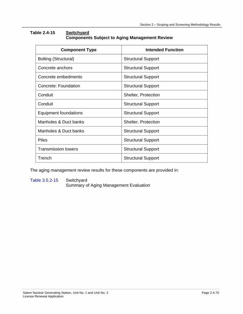
Section 2 – Scoping and Screening Methodology Results
Salem Nuclear Generating Station, Unit No. 1 and Unit No. 2 Page 2.4-70 License Renewal Application
Table 2.4-15 Switchyard Components Subject to Aging Management Review
Component Type Intended Function
Bolting (Structural) Structural Support
Concrete anchors Structural Support
Concrete embedments Structural Support
Concrete: Foundation Structural Support
Conduit Shelter, Protection
Conduit Structural Support
Equipment foundations Structural Support
Manholes & Duct banks Shelter, Protection
Manholes & Duct banks Structural Support
Piles Structural Support
Transmission towers Structural Support
Trench Structural Support The aging management review results for these components are provided in: Table 3.5.2-15 Switchyard Summary of Aging Management Evaluation
Section 2 – Scoping and Screening Methodology Results
Salem Nuclear Generating Station, Unit No. 1 and Unit No. 2 Page 2.4-71 License Renewal Application
2.4.16 Turbine Building
Structure Purpose The common Turbine Building is a steel framed and reinforced concrete structure enclosed with precast concrete panels and steel siding which is located immediately east of the Service Building and also east of, and separated from, the Salem Generating Stations (SGS) Unit 1 and Unit 2 Containment Structures. The Turbine Building is a multi-story structure approximately 170 by 610 feet in plan area, comprised of structural steel framing, precast concrete panels, metal siding, masonry walls, and reinforced concrete walls, slabs, foundation mat, and roof. The reinforced concrete foundation mat is supported on concrete filled steel pipe piles. The above ground exterior walls are pre-cast concrete panels and insulated metal siding. The roof is a reinforced concrete slab. The main turbine and generator housings extend above the roof. Moisture separators, feedwater heaters, and associated piping are also located on the Turbine Building roof. The building roof also supports the turbine building gantry cranes. There are also a number of hatches and ventilation openings on the roof. The Turbine Building is classified as a non-Category I structure designed to BOCA requirements. The primary structural framing includes heavy steel bracing and is designed to prevent Turbine Building collapse that could affect external safety-related structures or components under design basis earthquake conditions and as a result of loads imposed by a design basis tornado. Metal siding which is designed to blow out to relieve tornado generated differential pressure has also been provided on a portion of the Turbine Building exterior walls. The purpose of the building is to provide structural support, shelter, and protection for nonsafety-related systems, structures, and components during normal plant operation. The Turbine Building contains steam and power conversion systems components, and the support systems and components necessary to support Fire Protection, Station Blackout, and Anticipated Transients Without Scram. The Turbine Building also contains certain nonsafety-related electrical and mechanical components which perform intended functions considered important to safety by providing input signals and actuation devices for the reactor trip and engineered safety features actuation systems and by providing a means for feedwater isolation. These components which perform intended functions considered important to safety are evaluated with the Reactor Protection System and the Main Condensate and Feedwater System. Included in the boundary of the Turbine Building are reinforced concrete elements of the building, precast concrete panels, metal siding, metal decking, cable trays, concrete embedments, masonry walls, doors, hatches, compressible joints and seals, conduit, expansion or control joints, racks, frames, enclosures, structural steel, miscellaneous steel, bolting, penetration sleeves, penetration seals, roofing seals and flashing, and tube track. Assessment of the Turbine Building boundary concluded that the building is in scope of license renewal in its entirety. Refer to the "Components Subject to Aging Management Review" table below for a complete list of components included in the boundary of the Turbine Building. Not included in the boundary of the Turbine Building are cranes and hoists, fire barriers, piping and component insulation, and component supports. Piping and component insulation are evaluated separately with the Piping and Component Insulation Commodity Group. Cranes and hoists are evaluated separately with the Cranes and Hoists system, fire barriers

Section 2 – Scoping and Screening Methodology Results
Salem Nuclear Generating Station, Unit No. 1 and Unit No. 2 Page 2.4-72 License Renewal Application
are evaluated separately with the Fire Protection System, and the component supports are evaluated with the Component Supports Commodity Group. For more detailed information, see UFSAR Sections 3.3.2.3, and 3.8.4.3. Reason for Scope Determination The Turbine Building is not in scope under 10 CFR 54.4(a)(1) because no portions of the structure are safety-related or relied upon to remain functional during and following design basis events. It meets 10 CFR 54.4(a)(2) because the structure provides physical support, shelter, and protection for nonsafety-related systems, structures, and components (SSCs) whose failure could prevent satisfactory accomplishment of function(s) identified for 10 CFR 54.4(a)(1). It also meets 10 CFR 54.4(a)(3) because it provides physical support, shelter and protection for systems, structures, and components (SSCs) relied upon in safety analyses or plant evaluations to perform a function that demonstrates compliance with the Commission's regulations for Fire Protection (10 CFR 50.48), Anticipated Transients Without Scram (10 CFR 50.62), and Station Blackout (10 CFR 50.63). The Turbine Building is not relied upon in any safety analyses or plant evaluations to perform a function that demonstrates compliance with the Commission's regulations for Environmental Qualification (10 CFR 50.49), or Pressurized Thermal Shock (10 CFR 50.61). System Intended Functions 1. Provides physical support, shelter, and protection for nonsafety-related systems, structures, and components (SSCs) whose failure could prevent satisfactory accomplishment of function(s) identified for 10 CFR 54.4 (a)(1). 10 CFR 54.4(a)(2) 2. Provides physical support, shelter, and protection for systems structures and components relied upon in safety analyses or plant evaluations to perform a function that demonstrates compliance with the Commission's regulations for Fire Protection (10 CFR 50.48). 10 CFR 54.4(a)(3) 3. Provides physical support, shelter, and protection for systems, structures, and components relied upon in safety analyses or plant evaluations to perform a function that demonstrates compliance with the Commission's regulations for Anticipated Transient Without Scram (10 CFR 50.62). 10 CFR 54.4(a)(3) 4. Provides physical support, shelter, and protection for systems structures and components relied upon in safety analyses or plant evaluations to perform a function that demonstrates compliance with the Commission's regulations for Station Blackout (10 CFR 50.63). 10 CFR 54.4(a)(3) UFSAR References 1.3.1 3.3.2.3 3.6.5.13 3.8.4.3 License Renewal Boundary Drawings LR-204802
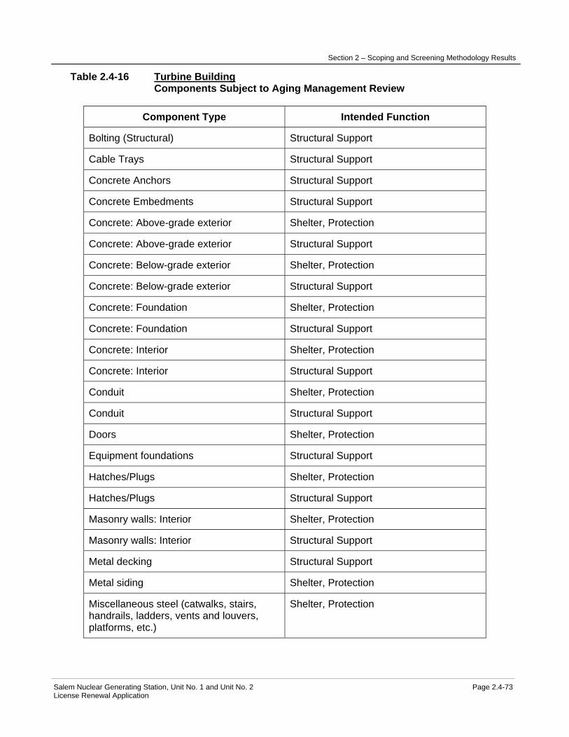
Section 2 – Scoping and Screening Methodology Results
Salem Nuclear Generating Station, Unit No. 1 and Unit No. 2 Page 2.4-73 License Renewal Application
Table 2.4-16 Turbine Building Components Subject to Aging Management Review
Component Type Intended Function
Bolting (Structural) Structural Support
Cable Trays Structural Support
Concrete Anchors Structural Support
Concrete Embedments Structural Support
Concrete: Above-grade exterior Shelter, Protection
Concrete: Above-grade exterior Structural Support
Concrete: Below-grade exterior Shelter, Protection
Concrete: Below-grade exterior Structural Support
Concrete: Foundation Shelter, Protection
Concrete: Foundation Structural Support
Concrete: Interior Shelter, Protection
Concrete: Interior Structural Support
Conduit Shelter, Protection
Conduit Structural Support
Doors Shelter, Protection
Equipment foundations Structural Support
Hatches/Plugs Shelter, Protection
Hatches/Plugs Structural Support
Masonry walls: Interior Shelter, Protection
Masonry walls: Interior Structural Support
Metal decking Structural Support
Metal siding Shelter, Protection
Miscellaneous steel (catwalks, stairs, handrails, ladders, vents and louvers, platforms, etc.)
Shelter, Protection

Section 2 – Scoping and Screening Methodology Results
Salem Nuclear Generating Station, Unit No. 1 and Unit No. 2 Page 2.4-74 License Renewal Application
Component Type Intended Function
Miscellaneous steel (catwalks, stairs, handrails, ladders, vents and louvers, platforms, etc.)
Structural Support
Panels, Racks, Cabinets, and Other Enclosures
Shelter, Protection
Panels, Racks, Cabinets, and Other Enclosures
Structural Support
Penetration seals Shelter, Protection
Penetration sleeves Structural Support
Piles Structural Support
Precast Panel Shelter, Protection
Precast Panel Structural Support
Roofing membrane Shelter, Protection
Seals, gaskets, and moisture barriers (caulking, flashing and other sealants)
Shelter, Protection
Steel Components: All structural steel Structural Support
Tube Track Structural Support The aging management review results for these components are provided in: Table 3.5.2-16 Turbine Building Summary of Aging Management Evaluation

Section 2 – Scoping and Screening Methodology Results
Salem Nuclear Generating Station, Unit No. 1 and Unit No. 2 Page 2.4-75 License Renewal Application
2.4.17 Yard Structures
Structure Purpose The Yard Structures include the compressed gas storage areas, tank foundations and dikes, pipe support structures, Circulating Water System piping foundations, turbine crane runway extensions, manholes, handholes and duct banks, miscellaneous yard structures, miscellaneous yard enclosures, transformer foundations, trenches, and yard drainage system. Compressed gas storage areas: Compressed gas storage areas are comprised of the carbon dioxide storage area, hydrogen storage area, nitrogen storage area, and gas bottle storage shed. The compressed gas storage areas consist of reinforced concrete slabs on grade that may be enclosed with a chain link fence or other barriers and located in the yard area. The gas bottle storage shed also consists of reinforced concrete slab on grade but covered with metal decking supported from steel framing. The shed is divided into several bays separated by masonry walls. The compressed gas storage areas are nonsafety-related and separated from safety-related SSCs such that their failure would not impact a safety-related function. The compressed gas storage areas do not perform an intended function and are not in scope for license renewal. Tank foundations and dikes: The tank foundations and dikes consist of the fuel oil storage tank foundation and dike, fresh water and fire protection water tank foundations, demineralized water tanks foundations, and the sodium hypochlorite tanks foundations and dike. The fuel oil storage tank foundation and dike is located south of the Containment Structure and adjacent to the Delaware River shoreline. The foundation consists of a reinforced concrete slab supported on steel pipe piles filled with concrete. The tank is surrounded by an earthen dike, which is lined with a liquid retaining membrane to contain oil spills. The fuel oil delivery area, which is located adjacent to the tank, consists of a shallow basin created by a concrete slab on grade and a 6-inch curb all around to retain potential oil spills. The slab also contains the fuel oil transfer pump and foundation. The southeastern portion of the dike that is directly adjacent or along the shoreline is evaluated as a part of the Shoreline Protection and Dike. The fuel oil storage tank foundation, the portion of the dike not included with the Shoreline Protection & Dike, and the fuel delivery area slab are nonsafety-related and separated from safety-related systems, structures, and components such that their failure would not impact a safety-related function. The fuel oil tank foundation, fuel oil delivery area slab, and the portion of the dike not included with the Shoreline Protection and Dike does not perform an intended function and is not in scope for license renewal. The fresh water and fire protection water tank foundations are two octagonal reinforced concrete slabs supported by steel pipe piles filled with concrete. The tank foundations are located northeast of the Containment Structure in the yard, separated from safety-related systems, structures, and components (SSCs) such that their failure would not impact a safety-related function. The tank foundations for the fresh water and fire protection tanks support tanks required for the Fire Protection System and are, therefore, in scope for license renewal.

Section 2 – Scoping and Screening Methodology Results
Salem Nuclear Generating Station, Unit No. 1 and Unit No. 2 Page 2.4-76 License Renewal Application
The demineralized water tanks foundations are two reinforced concrete foundations supported on steel pipe piles filled with concrete. The foundations are located southeast of the Containment Structure and south of the Turbine Building, separated from safety-related systems, structures, and components (SSCs) such that their failure would not impact a safety-related function. The tank foundations for the demineralized water tanks are in scope for license renewal because they provide support for tanks that are credited as a water source during a Station Blackout event. The sodium hypochlorite tanks foundations and dike are located south of the Containment Structure and north of the Circulating Water Intake Structure. The foundations consist of two reinforced concrete slabs supported on steel pipe piles filled with concrete. The two tanks are surrounded by an engineered fill dike sealed with bitumastic oil to contain potential spills. The sodium hypochlorite unloading station, which is located adjacent to the tanks, consists of a shallow basin formed by a concrete slab on grade and a 9-inch curb all around to retain potential spills. The sodium hypochlorite tanks foundations, the dike and the hypochlorite unloading station slab are nonsafety-related, and separated from safety-related SSCs such that their failure would not impact a safety-related function. These structures do not perform an intended function and are not in scope for license renewal. Pipe support structures: The pipe support structures are comprised of structural steel support frames for Main Steam System, Main Condensate and Feedwater System, and Heating Water and Heating Steam System piping routed in the yard. The steel structures are supported from reinforced concrete spread footings. The support structures for the Main Steam System and the Main Condensate and Feedwater System piping that are routed adjacent to safety-related structures and have been designed to limit pipe whip to prevent damage to the safety-related SSCs. The support structures also provide structural support for piping and piping components credited for Fire Protection and Station Blackout. The support structures perform a license renewal intended function and are in scope for license renewal. The Heating Water and Heating Steam System piping routed in the yard is not in scope for license renewal. However, its support structures between the SBO Compressor Building and Turbine Building provide structural support for Compressed Air System piping and piping components credited for Station Blackout. As a result, the support structures for the Compressed Air System piping, credited for Station Blackout, are in scope for license renewal. Circulating Water System piping foundations: The Circulating Water System intake and discharge piping is routed underground between the circulating water intake structure and the Delaware River and the Turbine Building. The piping is supported on reinforced concrete slab founded on steel pipe piles filled with concrete. In areas where the piping is routed underneath buildings (i.e. Service Building) it is encased in concrete or contained in reinforced concrete box sections. The Circulating Water System piping routed in the yard does not perform a license renewal intended function and failure of the foundations will not impact a safety-related function. The foundations, therefore, are not in scope for license renewal; except for areas where the foundation is common with foundation for in scope structures. In this case, the foundation is evaluated with the in scope structure.

Section 2 – Scoping and Screening Methodology Results
Salem Nuclear Generating Station, Unit No. 1 and Unit No. 2 Page 2.4-77 License Renewal Application
Turbine crane runway extensions: The turbine crane runway extensions are structural steel frames supported on reinforced concrete foundations located outdoors in the yard area located immediately adjacent to the Turbine Building and which are separated sufficiently from safety related SSCs such that their failure would not impact a safety-related function. The turbine cranes are not in scope for license renewal. However, its support structures north of the Unit 2 turbine building provide structural support for Compressed Air System piping and piping components credited for SBO. As a result, the turbine crane runway extension support structures north of the Unit 2 turbine building are in scope for license renewal. Manholes, handholes and duct banks: Manholes and handholes consist of reinforced concrete structures buried underground with a concrete panel on top. The manholes have a removable cover to allow plant personnel access to electrical cables routed in duct banks. Manholes and handholes serve as intermediate connection point(s) of duct banks routed in the yard area. Duct banks are comprised of the placement of multiple raceways in an excavated trench in the yard that are encased in concrete and then backfilled with soil or engineered compacted backfill. The duct banks are used to route nonsafety-related and safety-related cables between structures and also in the switchyard area. Manholes, handholes, and duct banks that contain safety-related cables, and cables credited for Station Blackout or Anticipated Transients Without Scram perform a license renewal intended function and are in scope for license renewal. Miscellaneous yard structures: Miscellaneous yard structures are comprised of civil features located in the yard area that are not uniquely tied to a group of common structures in the yard. These miscellaneous yard structures include roadways, light poles, sidewalks, fences, bollards, reinforced concrete foundation slabs from buildings that have been removed from the site, concrete pads for commercial grade HVAC units for office buildings, abandoned equipment concrete foundations, and miscellaneous yard sheds and foundations. The miscellaneous yard structures are nonsafety-related and separated from safety-related systems, structures, and components such that their failure would not impact a safety-related function. The miscellaneous yard structures do not perform an intended function and are not in scope for license renewal. Miscellaneous yard enclosures: The 910 building is a concrete block single story structure on a reinforced concrete pad foundation that is located east of the Containment Structure. This building is currently used as a craft muster and office area primarily during outages and is nonsafety-related and separated from safety-related systems, structures, and components such that its failure would not impact a safety-related function. The 910 building does not perform an intended function and is not in scope for license renewal. The plant vent radiation monitoring enclosures are small commercial grade steel siding sheds supported on a concrete foundation pad. The enclosures house safety-related post accident

Section 2 – Scoping and Screening Methodology Results
Salem Nuclear Generating Station, Unit No. 1 and Unit No. 2 Page 2.4-78 License Renewal Application
radiation monitoring instrumentation. The Salem Generating Station (SGS) Unit 1 and Unit 2 plant vent radiation monitoring enclosures are located adjacent to SGS Unit 1 and Unit 2 fuel handling buildings. These enclosures shelter and protect safety-related post accident radiation monitoring instrumentation equipment and are, therefore, in scope for license renewal. Transformer foundations: Transformer foundations are reinforced concrete slabs that provide structural support for station transformers located in the yard. The foundations can be concrete slabs on grade, concrete slabs that are cast on a subgrade foundation several feet below grade or on piles with perimeter walls with a pedestal type concrete equipment pad on the foundation slab that provides the structural support for the transformer and transformer support steel mounting. Transformer foundations do not perform a safety-related function and are separated from SSCs such that their failure would not impact a safety-related function. The transformer foundations and separating walls do not perform an intended function and are not in scope for license renewal. The transformers that are required to support Station Blackout restoration are evaluated with the Switchyard. Trenches: Trenches are a reinforced concrete rectangular box structure with a removable top cover in the yard area, with either concrete, metal grating or metal plate covering the top. The trenches are used to route piping and components for not in scope plant systems. The top of the trenches are located at approximately plant grade with the remaining portion of the trench below grade such that their failure would not impact a safety-related function. The trenches do not perform an intended function and are not in scope for license renewal. Yard drainage system: The yard drainage system is comprised of reinforced concrete pipe, fiberglass pipe contained in steel pipe, ductile iron pipe, reinforced concrete catch basins, a single steel valve vault, and reinforced concrete oil skimming tanks. The catch basins are typically covered with grating to allow inflow of storm water. The oil skimming tanks are provided to separate oily waste from storm water prior to its discharge into the Delaware River. The yard drainage system is provided to drain the station's yard area during normal and severe rainstorms. The yard drainage system does not perform an intended function and is not in scope for license renewal, except for the two catch basins located immediately north and south of the Fire Pump House which are credited with accepting fuel oil from drains in the Fire Pump House to support the fire protection intended function. These two catch basins are, therefore, in scope for license renewal. The purpose of the Yard Structures is to provide structural support, shelter, and protection for safety-related and nonsafety-related components and commodities, including components credited for Station Blackout, Fire Protection, and Anticipated Transients Without Scram. The yard drainage system permits drainage of the yard area during normal and severe rainstorms. Included in the boundary of the Yard Structures are components that makeup compressed gas storage areas, tank foundations and dikes, pipe support structures, Circulating Water System piping foundations, Service Water System piping and manways, turbine crane runway extensions, manholes, handholes and duct banks, miscellaneous yard structures,

Section 2 – Scoping and Screening Methodology Results
Salem Nuclear Generating Station, Unit No. 1 and Unit No. 2 Page 2.4-79 License Renewal Application
miscellaneous yard enclosures, transformer foundations, trenches, and yard drainage system. Components of the fresh water and fire protection water tank foundations, the demineralized water tanks foundations, pipe support structures, turbine crane runway extensions, manhole, handholes, and duct banks that contain electrical cables in the scope of license renewal, and plant vent radiation monitoring enclosures are also included in the boundary of the Yard Structures and are in scope for license renewal. These components include foundations, structural steel, bolting, conduit, cable trays, concrete anchors, manholes, handholes, and duct banks, equipment foundations, hatches/plugs, metal siding, metal decking, piles, and racks, panels, and enclosures are in scope for license renewal. The other Yard Structures and their components do not perform a license renewal intended function and are not in the scope of license renewal. Refer to "Components Subject to Aging Management Review" table below for a complete list of components included in the boundary of the Yard Structures. Not included in the boundary of the Yard Structures are component supports, piping and component insulation, shoreline protection, oil handling equipment, underground piping including service water piping, support for safety-related tanks, turbine building cranes, and Switchyard components. Component supports are separately evaluated with the Component Supports Commodity Group. The piping and component insulation is evaluated with the Piping and Component Insulation Commodity Group. The turbine building cranes are separately evaluated with Cranes and Hoists, and the components in the switchyard are evaluated with the Switchyard Structures. The shoreline protection is evaluated with Shoreline Protection and Dike. The oil separators and foam house and other oil handling structures are evaluated with Oil Handling Structures. The safety-related outdoor tanks are supported on the Pipe Tunnel roof which is evaluated separately with the Pipe Tunnel. The service water discharge manways are addressed as service water piping which is evaluated with the Service Water System. For more detailed information, see UFSAR Sections 2.2 and 2.4. Reason for Scope Determination The Yard Structures do not meet 10 CFR 54.4(a)(1) because they are not safety-related structures that are relied upon to remain functional during and following design basis events. They meet 10 CFR 54.4(a)(2) because failure of nonsafety-related portions of the structures could prevent satisfactory accomplishment of function(s) identified for 10 CFR 54.4(a)(1). It also meets 10 CFR 54.4(a)(3) because they provide physical support, shelter and protection for SSCs relied upon in safety analyses or plant evaluations to perform a function that demonstrates compliance with the Commission's regulations for Fire Protection (10 CFR 50.48), Anticipated Transients Without Scram (10 CFR 50.62), and Station Blackout (10 CFR 50.63). The Yard Structures are not relied upon in any safety analyses or plant evaluations to perform a function that demonstrates compliance with the Commission's regulations for Environmental Qualification (10 CFR 50.49) or Pressurized Thermal Shock (10 CFR 50.61). System Intended Functions 1. Provides physical support, shelter and protection for nonsafety-related systems, structures, and components whose failure could prevent satisfactory accomplishment of function(s) identified for 10 CFR 54.4 (a)(1). 10 CFR 54.4(a)(2)
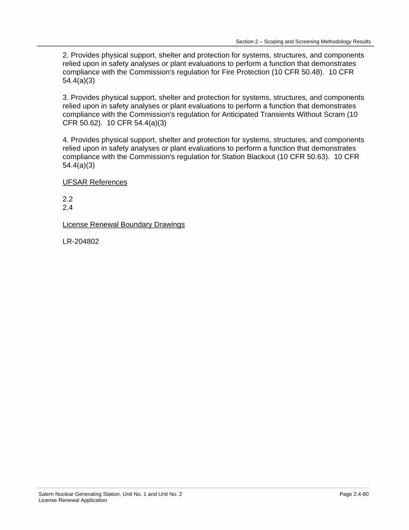
Section 2 – Scoping and Screening Methodology Results
Salem Nuclear Generating Station, Unit No. 1 and Unit No. 2 Page 2.4-80 License Renewal Application
2. Provides physical support, shelter and protection for systems, structures, and components relied upon in safety analyses or plant evaluations to perform a function that demonstrates compliance with the Commission's regulation for Fire Protection (10 CFR 50.48). 10 CFR 54.4(a)(3) 3. Provides physical support, shelter and protection for systems, structures, and components relied upon in safety analyses or plant evaluations to perform a function that demonstrates compliance with the Commission's regulation for Anticipated Transients Without Scram (10 CFR 50.62). 10 CFR 54.4(a)(3) 4. Provides physical support, shelter and protection for systems, structures, and components relied upon in safety analyses or plant evaluations to perform a function that demonstrates compliance with the Commission's regulation for Station Blackout (10 CFR 50.63). 10 CFR 54.4(a)(3) UFSAR References 2.2 2.4 License Renewal Boundary Drawings LR-204802

Section 2 – Scoping and Screening Methodology Results
Salem Nuclear Generating Station, Unit No. 1 and Unit No. 2 Page 2.4-81 License Renewal Application
Table 2.4-17 Yard Structures Components Subject to Aging Management Review
Component Type Intended Function
Bolting (Structural) Structural Support
Cable Trays Structural Support
Concrete Anchors Structural Support
Concrete Embedments Structural Support
Concrete: Above-grade exterior Missile Barrier
Concrete: Above-grade exterior Shelter, Protection
Concrete: Above-grade exterior Structural Support
Concrete: Below-grade exterior Missile Barrier
Concrete: Below-grade exterior Shelter, Protection
Concrete: Below-grade exterior Structural Support
Concrete: Foundation Shelter, Protection
Concrete: Foundation Structural Support
Concrete: Interior Shelter, Protection
Concrete: Interior Structural Support
Conduit Shelter, Protection
Conduit Structural Support
Equipment foundations Structural Support
Hatches/Plugs (Manhole/handhole covers)
Missile Barrier
Hatches/Plugs (Manhole/handhole covers)
Shelter, Protection
Hatches/Plugs (Manhole/handhole covers)
Structural Support
Manholes, Handholes & Duct Banks Shelter, Protection
Manholes, Handholes & Duct Banks Structural Support
Metal decking Shelter, Protection
Metal decking Structural Support

Section 2 – Scoping and Screening Methodology Results
Salem Nuclear Generating Station, Unit No. 1 and Unit No. 2 Page 2.4-82 License Renewal Application
Component Type Intended Function
Metal siding Shelter, Protection
Metal siding Structural Support
Panels, Racks, Cabinets, and Other Enclosures
Shelter, Protection
Panels, Racks, Cabinets, and Other Enclosures
Structural Support
Piles Structural Support
Seals, gaskets, and moisture barriers (caulking, flashing and other sealants)
Shelter, Protection
Steel Components: All structural steel Pipe Whip Restraint
Steel Components: All structural steel Structural Support The aging management review results for these components are provided in: Table 3.5.2-17 Yard Structures Summary of Aging Management Evaluation

Section 2 - Scoping and Screening Methodology and Results
Salem Nuclear Generating Station, Unit No. 1 and Unit No. 2 Page 2.5-1 License Renewal Application
2.5 SCOPING AND SCREENING RESULTS: ELECTRICAL AND INSTRUMENTATION AND CONTROLS (I&C) SYSTEMS
The determination of electrical systems that fall within the scope of license renewal is made through the application of the process described in Section 2.1. The results of the electrical systems scoping review are contained in Section 2.2.
Subsection 2.1.6.1 provides the screening methodology for determining which component/commodity groups within the scope of 10 CFR 54.4 meet the requirements contained in 10 CFR 54.21(a)(1). The component/commodity groups that meet those screening requirements are identified in this section. These identified component/commodity groups consequently require an aging management review.
As described in Subsection 2.1.6.1, the screening for electrical and I&C components was performed on a commodity group basis for the in-scope electrical and I&C systems as well as the electrical and I&C component types associated with in-scope mechanical systems listed in Table 2.2-1.
Components which support or interface with electrical and I&C components, for example, cable trays, conduits, instrument racks, panels and enclosures, are assessed as part of the Component Supports Commodity Group in Section 2.4.2.
2.5.1 ELECTRICAL/I&C COMPONENT COMMODITY GROUPS
After identifying passive commodity groups in accordance with the guidance of NEI 95-10, commodity groups that are subject to periodic replacement were also screened out. Commodity groups were then evaluated to identify whether specific commodities perform a license renewal intended function, thus determining whether they are subject to aging management review.
UFSAR References
Additional system details are included in the UFSAR Sections 7, 8 and 9.
Evaluation Boundaries
In addition to the plant electrical and I&C components, certain Switchyard components required to restore offsite power following a station blackout (SBO) were included within the scope of license renewal. The evaluation boundaries of the offsite power system are described below.
The purpose of the offsite power system and Switchyard is to provide the electrical interconnection between Salem and the offsite transmission network. Restoration is defined as the re-powering of the plant AC distribution system from offsite sources and/or on site emergency AC sources. For Salem, this includes the portion of the plant electrical system used to connect the in-scope AC distribution system equipment to offsite power and by definition recover from an SBO event. For Salem, the boundary between the electrical transmission

Section 2 - Scoping and Screening Methodology and Results
Salem Nuclear Generating Station, Unit No. 1 and Unit No. 2 Page 2.5-2 License Renewal Application
network and the plant electrical distribution system and equipment has been defined at six 500kV switchyard circuit breakers: breakers 10X and 11X (New Freedom), 20X and 21X (Orchard), and 30X and 31X (Hope Creek). Long-lived passive electrical commodities included in the scope of license renewal on the plant side of this boundary are: switchyard bus and connections, high voltage insulators, substation structures and supports, inaccessible medium voltage cables, metal enclosed bus, insulated cables and connections, and cable connections (metallic parts).
A simplified diagram of the SBO recovery path and the key plant electrical distribution systems is shown in Figure 2.1-2.

Section 2 – Scoping and Screening Methodology and Results
Salem Nuclear Generating Station, Unit No. 1 and Unit No. 2 Page 2.5-3 License Renewal Application
2.5.2 ELECTRICAL COMPONENT COMMODITY GROUPS 2.5.2.1 Identification of Electrical Component Commodity Groups
The first step of the screening process for electrical component commodity groups is to use plant documentation to identify the electrical components within the electrical, I&C and mechanical systems based on plant design documentation, drawings, and the Component Data Module (SAP CDM), as well as by interfacing with the parallel mechanical and civil screening efforts. The electrical component commodity groups identified at Salem are listed below. This list includes electrical commodity groups identified in NEI 95-10 Appendix B in addition to commodity groups added per NUREG-1800 Table 2.1-5, the EPRI License Renewal Electrical Handbook or unique to Salem. Electrical Component Commodity Groups for In-Scope Systems: − Alarm Units − Analyzers − Annunciators − Batteries − Cable Connections – Metallic Parts − Cable Tie-Wraps − Chargers − Circuit Breakers − Communication Equipment − Connection Contacts − Converters − Electric Heaters − Electrical Controls and Panel Internal Assemblies − Electrical Penetrations − Elements, RTDs, Sensors, Themocouples, Transducers − Fuse Holders − Fuses − Generators, Motors − Heat Trace − High Voltage Insulators − Indicators − Insulated Cables and Connections − Inverters − Isolators − Light Bulbs − Loop Controllers − Metal Enclosed Bus − Meters − Motor Generator Sets − Power Supplies − Radiation Monitors − Recorders − Regulators

Section 2 – Scoping and Screening Methodology and Results
Salem Nuclear Generating Station, Unit No. 1 and Unit No. 2 Page 2.5-4 License Renewal Application
− Relays (and Bistables) − Signal Conditioners − Solenoid Operators − Solid State Devices − Splices − Surge Arresters − Switches − Switchgear, Load Centers, Motor Control Centers, Distribution Panel Internal
Component Assemblies − Switchyard Bus and Connections − Terminal Blocks − Transformers − Transmission Conductors and Connections − Transmitters − Uninsulated Ground Conductors
2.5.2.2 Application of Screening Criterion 10 CFR 54.21 (a)(1)(i) to the Electrical
Component Commodity Groups Following the identification of the electrical commodity groups, the criteria of 10 CFR 54.21 (a)(1)(i) were applied to identify commodity groups that perform their functions without moving parts or without a change in configuration or properties. The following electrical commodity groups were determined to meet the screening criteria of 10 CFR 54.21 (a)(1)(i): − Cable Connections - Metallic Parts − Cable Tie-Wraps − Connector Contacts for Electrical Connectors Exposed to Borated Water − Electrical Equipment Subject to 10 CFR 50.49 Environmental Qualification
Requirements − Electrical Penetrations − Fuse Holders − High Voltage Insulators − Insulated Cables and Connections − Metal Enclosed Bus − Splices − Switchyard Bus and Connections − Terminal Blocks − Transmission Conductors and Connections − Uninsulated Ground Conductors
2.5.2.3 Elimination of Electrical Component Commodity Groups With No License Renewal Intended Functions The following electrical commodity groups were determined to not have a license renewal intended function:

Section 2 – Scoping and Screening Methodology and Results
Salem Nuclear Generating Station, Unit No. 1 and Unit No. 2 Page 2.5-5 License Renewal Application
Cable Tie-Wraps Tie-wraps are used in cable installations as cable ties. Cable ties hold groups of cables together for restraint and ease of maintenance. Cable ties are used to bundle wires and cables together to keep the wire and cable runs neat and orderly. Cable ties are used to restrain wires and cables within raceways to facilitate cable installation. There are no current license basis requirements for Salem that tie-wraps remain functional during and following design basis events. Cable ties are not credited for maintaining cable ampacity, ensuring maintenance of cable minimum bending radius, or maintaining cables within vertical raceways at Salem. The seismic qualification of cable trays does not credit the use of cable ties. Tie-wraps are not credited in the Salem design basis in terms of any 10 CFR 54.4 intended function. Therefore, cable tie-wraps are not within the scope of license renewal and are not subject to aging management review. Transmission Conductors and Connections
The Transmission Conductors and Connections commodity group forms a portion of the circuits that supply power from the main generator to the electric utility grid. There are no transmission conductors and connections in the SBO recovery path, and they do not perform an intended function for license renewal. Therefore, Transmission Conductors and Connections are not subject to aging management review. Uninsulated Ground Conductors The Uninsulated Ground Conductors commodity group is comprised of grounding cable and associated connectors. Ground conductors are provided for equipment and personnel protection. They do not perform an intended function for license renewal. Therefore, Uninsulated Ground Conductors are not subject to aging management review.
2.5.2.4 Application of Screening Criterion 10 CFR 54.21 (a)(1)(ii) to Electrical
Component Commodity Groups
The 10 CFR 54.21 (a)(1)(ii) screening criterion was applied to the specific commodity groups that remained following application of the 10 CFR 54.21 (a)(1)(i) criterion. 10 CFR 54.21 (a)(1)(ii) allows the exclusion of those commodity groups that are subject to replacement based on a qualified life or specified time period. The only electrical commodity groups identified for exclusion by the criteria of 10 CFR 54.21 (a)(1)(ii) are electrical and I&C components included in the Salem Environmental Qualification (EQ) Program. This is because electrical and I&C components included in the EQ Program have defined qualified lives and are replaced prior to the expiration of their qualified lives. No electrical or I&C components within the Salem EQ Program are subject to aging management review in accordance with the screening criteria of 10 CFR 54.21 (a)(1)(ii). See Section 4.7 for the TLAA evaluation of the Salem EQ Program. The remaining commodity groups, all or part of which are not in the EQ Program, require aging management review and are discussed below.
Section 2 – Scoping and Screening Methodology and Results
Salem Nuclear Generating Station, Unit No. 1 and Unit No. 2 Page 2.5-6 License Renewal Application
2.5.2.5 Electrical Component Commodity Groups Subject to Aging Management Review
The electrical component commodity groups subject to aging management review are identified in Table 2.5.2-1, along with the associated intended functions. These electrical component commodity groups are further described below.
2.5.2.5.1 Cable Connections - Metallic Parts
The Cable Connectors (Metallic Parts) commodity group includes metallic portions of cable connections that are not included in the EQ Program. The metallic connections evaluated include splices, threaded connectors, compression type termination lugs and terminal blocks. Therefore, Cable Connections (Metallic Parts) meet the screening criterion of 10 CFR 54.21(a)(1)(ii) and are subject to aging management review.
2.5.2.5.2 Connector Contacts for Electrical Connectors Exposed to Borated
Water Leakage
The Connector Contacts for Electrical Connectors Exposed to Borated Water Leakage commodity group includes electrical connections that are not included in the EQ Program and are located in Containment, the Fuel Handling Building, or the Auxiliary Building. These electrical connections meet the screening criterion of 10 CFR 54.21(a)(1)(ii) and are subject to aging management review.
2.5.2.5.3 Electrical Penetrations
Environmentally qualified electrical penetrations are managed under the Environmental Qualification Program, which is evaluated as a time-limited aging analysis. The electrical continuity of the non-environmentally qualified electrical penetrations is managed under the Electrical Cables and Connections Not Subject to 10 CFR 50.49 Environmental Qualification Requirements program. The pressure boundary function of electrical penetrations is included in Section 2.4.3, Containment Structure.
2.5.2.5.4 Fuse Holders
The Fuse Holder commodity group includes fuse holders that are not part of a larger active assembly and are not included in the EQ Program. Both metallic and non-metallic portions of fuse holders, that are not part of a larger active assembly and are not included in the EQ Program, meet the screening criterion of 10 CFR 54.21(a)(1)(ii) and are subject to aging management review. Insulating portions of fuse holders are evaluated with insulated cables and connections (Section 2.5.2.5.1).
2.5.2.5.5 High Voltage Insulators
The High Voltage Insulators commodity group supports a portion of the circuits that supply power from the electric utility transmission system and

Section 2 – Scoping and Screening Methodology and Results
Salem Nuclear Generating Station, Unit No. 1 and Unit No. 2 Page 2.5-7 License Renewal Application
Switchyard to plant buses, to power in-scope license renewal components used for recovery from a station blackout event. High Voltage Insulators are not included in the EQ program. Therefore, High Voltage Insulators meet the screening criterion of 10 CFR 54.21(a)(1)(ii) and are subject to an aging management review.
2.5.2.5.6 Insulated Cables and Connections
The insulated cables and connections commodity group was separated for aging management review into subcategories based on their treatment in NUREG-1801:
− Insulated Cables and Connections − Insulated Cables and Connections Used in Instrumentation Circuits − Insulated Inaccessible Medium-Voltage Cables
Insulated cables and connections included in this review are: − Electrical Penetration Pigtails − Splices − Terminal Blocks − Insulating Portions of Fuse Holders
Numerous insulated cables and connections are included in the EQ Program and, therefore, are not subject to an aging management review in accordance with the screening criteria of 10 CFR 54.21 (a)(1)(ii). Insulated cables and connections not included in the EQ Program meet the criterion of 10 CFR 54.21(a)(1)(ii) and are subject to an aging management review. Insulated cables and connections inside the enclosure of an active device (e.g., motor leads and connections, cables and connections internal to relays, chargers, switchgear, transformers, power supplies) are maintained along with the other subcomponents inside the enclosure and are not subject to an aging management review.
2.5.2.5.7 Metal Enclosed Bus
The Metal Enclosed Bus (MEB) commodity group consists of a small section of non-segregated bus work used to distribute 13 kV electrical power in the Salem switchyard. This portion of the power distribution system is in the scope of license renewal and supplies electrical power from the switchyard to plant buses to power in-scope license renewal components for recovery from a station blackout event. Therefore, metal enclosed bus meets the screening criterion of 10 CFR 54.21(a)(1)(ii) and is subject to aging management review.
2.5.2.5.8 Switchyard Bus and Connections
The Switchyard Bus and Connections commodity group forms a portion of the circuits that supply power from the electrical utility grid, to plant buses, to power in scope license renewal components, and for recovery from a station blackout. The Switchyard Bus and Connections are not included in the EQ

Section 2 – Scoping and Screening Methodology and Results
Salem Nuclear Generating Station, Unit No. 1 and Unit No. 2 Page 2.5-8 License Renewal Application
program. Therefore, Switchyard Bus and Connections meet the screening criterion of 10 CFR 54.21(a)(1)(ii) and are subject to an aging management review.
Table 2.5.2-1 Electrical Component Commodity Groups Subject to Aging
Management Review
Component Type Intended Functions Cable Connections - Metallic Parts Electrical Continuity Connector Contacts for Electrical Connectors Exposed to Borated Water Leakage
Electrical Continuity
Fuse Holders Electrical Continuity High Voltage Insulators Insulation - Electrical Insulated Cables and Connections Electrical Continuity
Electrical Continuity Insulation - Electrical
Metal Enclosed Bus
Shelter, Protection Switchyard Bus and Connections Electrical Continuity
The aging management review results for these components are provided in Table 3.6.2-1, Electrical Commodity Groups – Summary of Aging Management Evaluation.
Section 3 – Aging Management Review Results _________________________________________________________________________________________________
________________________________________________________________________ Salem Nuclear Generating Station, Unit No. 1 and Unit No. 2 Page 3.0-1 License Renewal Application
3.0 AGING MANAGEMENT REVIEW RESULTS
This section provides the results of the aging management review for those structures and components identified in Section 2.0 as being subject to aging management review.
Descriptions of the internal and external service environments that were used in the aging management review to determine aging effects requiring management are included in Table 3.0-1, Salem Internal Service Environments and Table 3.0-2, Salem External Service Environments. The environments used in the aging management reviews are listed in the Environment column. The third column identifies one or more of the NUREG-1801 Volume 2 environments that were used when comparing the Salem Aging Management Review results to the NUREG-1801 results.
Most of the Aging Management Review (AMR) results information in Section 3 is presented in the following two tables:
• Table 3.x.1 - where ‘3’ indicates the LRA section number, ‘x’ indicates the subsection number from NUREG 1801, Volume 1, and ‘1’ indicates that this is the first table type in Section 3. For example, in the Reactor Vessel, Internals, and Reactor Coolant System subsection, this table would be number 3.1.1, in the Engineered Safety Features subsection, this table would be 3.2.1, and so on. For ease of discussion, this table will hereafter be referred to in this Section as “Table 1.”
• Table 3.x.2-y - where ‘3’ indicates the LRA section number, ‘x’ indicates the subsection number from NUREG 1801, Volume 1, and ‘2’ indicates that this is the second table type in Section 3; and ‘y’ indicates the table number for a specific system. For example, for the Reactor Pressure Vessel, within the Reactor Vessel, Internals, and Reactor Coolant System subsection, this table would be 3.1.2-2. For the Residual Heat Removal System, within the Engineered Safety Features (ESF) subsection, this table would be 3.2.2-2. For the next system within the ESF subsection, it would be table 3.2.2-3. For ease of discussion, this table will hereafter be referred to in this section as “Table 2.”
TABLE DESCRIPTION
NUREG-1801, “Generic Aging Lessons Learned (GALL) Report,” contains the generic evaluation of existing plant programs. It documents the technical basis for determining where existing programs are adequate without modification, and where existing programs should be augmented for the extended period of operation. The evaluation results documented in the report indicate that many of the existing programs are adequate to manage the aging effects for particular structures or components, within the scope of license renewal, without change. The report also contains recommendations on specific areas for which existing programs should be augmented for license renewal. In order to take full advantage of NUREG-1801, a comparison between the AMR results and the tables of NUREG-1801 has been made. The results of that comparison are provided in the two tables.
Section 3 – Aging Management Review Results _________________________________________________________________________________________________
________________________________________________________________________ Salem Nuclear Generating Station, Unit No. 1 and Unit No. 2 Page 3.0-2 License Renewal Application
Table 1
The purpose of Table 1 is to provide a summary comparison of how the facility aligns with the corresponding tables of NUREG-1801, Volume 1. The table is essentially the same as Tables 3.1.1 through 3.6.1 provided in NUREG-1801, Volume 1, except that the “ID” and “Type” columns have been replaced by an “Item Number” column and the “Related Generic Item” and “Unique Item” columns have been replaced by a “Discussion” column.
The “Item Number” column provides the reviewer with a means to cross-reference from Table 2 to Table 1.
The “Discussion” column is used to provide clarifying or amplifying information. The following are examples of information that might be contained within this column:
• “Further Evaluation Recommended” information or reference to where that information is located
• The name of a plant specific aging management program being used
• Exceptions to the NUREG-1801 assumptions
• A discussion of how the line is consistent with the corresponding line item in NUREG-1801, Volume 1, when that may not be intuitively obvious
• A discussion of how the item is different than the corresponding line item in NUREG-1801, Volume 1, when it may appear to be consistent (e.g., when there is exception taken to an aging management program that is listed in NUREG-1801, Volume 1)
The format of Table 1 provides the reviewer with a means of aligning a specific Table 1 row with the corresponding NUREG-1801, Volume 1 table row, thereby allowing for the ease of checking consistency.
Table 2
Table 2 provides the detailed results of the aging management reviews for those components identified in LRA Section 2 as being subject to aging management review. There will be a Table 2 for each of the systems within a Chapter 3 Section grouping. For example, for Salem, the Engineered Safety Features System Group contains tables specific to the Containment Spray System (CS), Residual Heat Removal System (RHR), and the Safety Injection System (SI).
Table 2 consists of the following nine columns:
• Component Type
• Intended Function
• Material
• Environment
• Aging Effect Requiring Management

Section 3 – Aging Management Review Results _________________________________________________________________________________________________
________________________________________________________________________ Salem Nuclear Generating Station, Unit No. 1 and Unit No. 2 Page 3.0-3 License Renewal Application
• Aging Management Programs
• NUREG-1801 Volume 2 Item
• Table 1 Item
• Notes
Component Type – The first column identifies all of the component types from Section 2 of the LRA that are subject to aging management review. They are listed in alphabetical order.
Intended Function – The second column contains the license renewal intended functions for the listed component types. Definitions of intended functions are contained in Table 2.1-1.
Material – The third column lists the particular materials of construction for the component type.
Environment – The fourth column lists the environment to which the component types are exposed. Internal and external service environments are indicated and a list of these environments is provided in Tables 3.0-1 and 3.0-2, respectively.
Aging Effect Requiring Management – As part of the aging management review process, the aging effects/mechanisms required to maintain the intended function of the component type are identified for the material and environment combination. These aging effects/mechanisms requiring management are listed in the fifth column.
Aging Management Programs – The aging management programs used to manage the aging effects requiring management are listed in the sixth column of Table 2. Aging management programs are described in Appendix B.
NUREG-1801, Vol. 2 Item – Each combination of component type, material, environment, aging effect/mechanism requiring management, and aging management program that is listed in Table 2, is compared to NUREG-1801, Volume 2 with consideration given to the standard notes, to identify consistency. Consistency is documented by noting the appropriate NUREG-1801, Volume 2 item number in the seventh column of Table 2. If there is no corresponding item number in NUREG-1801, Volume 2, this cell block is left blank. Thus, a reviewer can readily identify the correlation between the plant-specific tables and the NUREG-1801, Volume 2 tables.
Table 1 Item – Each combination of component, material, environment, aging effect/mechanism requiring management, and aging management program that has an identified NUREG-1801, Volume 2 item number must also have a Table 3.x.1 line item reference number. The corresponding line item from Table 1 is listed in the eighth column of Table 2. If there is no corresponding item in NUREG-1801, Volume 1, this cell block in column eight is left blank. The Table 1 Item allows the information from the two tables to be correlated.
Notes – The notes provided in each Table 2 describe how the information in the table aligns with the information in NUREG-1801. Each Table 2 contains both standard lettered notes and plant-specific numbered notes.

Section 3 – Aging Management Review Results _________________________________________________________________________________________________
________________________________________________________________________ Salem Nuclear Generating Station, Unit No. 1 and Unit No. 2 Page 3.0-4 License Renewal Application
The standard lettered notes, e.g., A, B, C, etc., provide standard information regarding comparison of the Salem aging management review results with the NUREG-1801, Volume 2 Aging Management Table line item identified in the seventh column. In addition to the standard lettered notes, numbered plant-specific notes provide additional clarifying information when appropriate.
TABLE USAGE
Table 1
The reviewer evaluates each row in Table 1 by moving from left to right across the table. Since the Component, Aging Effect, Aging Management Programs and Further Evaluation Recommended information is taken directly from NUREG-1801, Volume 1, no further analysis of those columns is required. The information intended to help the reviewer the most in this table is contained within the Discussion column. Here the reviewer will be given information necessary to determine, in summary, how the Salem evaluations and programs align with NUREG-1801, Volume 1. This may be in the form of descriptive information within the Discussion column or the reviewer may be referred to other locations within the LRA for further information.
Table 2
Table 2 contains all of the Aging Management Review information for the plant, whether or not it aligns with NUREG-1801. For a given row within the table, the reviewer is able to see the intended function, material, environment, aging effect/mechanism requiring management and aging management program combination for a particular component type within a system. In addition, if there is a correlation between the combination in Table 2 and a combination in NUREG-1801, Volume 2, this will be identified by a referenced item number in column seven, NUREG-1801, Volume 2 Item. The reviewer can refer to the item number in NUREG-1801, Volume 2, if desired, to verify the correlation. If the column is blank, no corresponding combination in NUREG-1801, Volume 2 was found. As the reviewer continues across the table from left to right, within a given row, the next column is labeled Table 1 Item. If there is a reference number in this column, the reviewer is able to use that reference number to locate the corresponding row in Table 1 and see how the aging management program for this particular combination aligns with NUREG-1801.
Table 2 provides the reviewer with a means to navigate from the components subject to Aging Management Review (AMR) in LRA Section 2 all the way through the evaluation of the programs that will be used to manage the effects of aging of those components.
A listing of the abbreviations used in this section is provided in Section 1.6.
Cumulative Fatigue Damage and TLAAs in Table 2
A Fatigue analysis is a time-limited aging analysis (TLAA) as defined in 10 CFR 54.3. TLAAs are required to be evaluated in accordance with 10 CFR 54.21(c)(1). For those components subject to cumulative fatigue, the impact on existing TLAAs was evaluated and is addressed in Section 4.3.
Section 3 – Aging Management Review Results _________________________________________________________________________________________________
________________________________________________________________________ Salem Nuclear Generating Station, Unit No. 1 and Unit No. 2 Page 3.0-5 License Renewal Application
Where specified by NUREG-1801, Volume 2, the following rules were used when applying TLAA to the aging effects associated with cumulative fatigue for a component:
1. For all pressure retaining components in a system that are subject to the aging effects of cumulative fatigue, a TLAA is applied for component types, including piping and fittings, and valves.
2. The use of TLAA in the following tables indicates that the current licensing basis was reviewed for TLAAs and the fatigue analysis was evaluated where one exists for that component. However, not every component has an explicit fatigue analysis. In these instances, as stated in Section 4.3, piping and components were designed to codes and standards that require application of stress range reduction factors to account for cyclic thermal conditions. Maintaining plant thermal cycles within the code design limit ensures components such as piping, piping components, and bolting are within fatigue limits.

Section 3 – Aging Management Review Results _________________________________________________________________________________________________
________________________________________________________________________ Salem Nuclear Generating Station, Unit No. 1 and Unit No. 2 Page 3.0-6 License Renewal Application
Table 3.0-1 – Salem Internal Service Environments
Salem Environment Description NUREG-1801 Environments Used
For AMR Comparison
Air/Gas-Dry Air/Gas-Dry includes air with a very limited percentage of moisture present that has been treated to reduce the dew point well below the system operating temperature. This includes air downstream of dryers in air systems and includes the air inside systems with temperatures higher than the dew point that have surfaces that are normally dry. It also includes commercial grade gases (such as nitrogen, Freon, etc.) that are provided as a high quality product with little if any external contaminants.
Gas
Dried air
Air/Gas-Wetted Air/Gas-Wetted includes air/gas environments containing significant amounts of moisture where condensation or water pooling may occur. This environment includes air with enough moisture to facilitate loss of material in steel caused by general, pitting, and crevice corrosion. Any internal air environment that does not meet the definition of Air/Gas – Dry is categorized as Air/Gas – Wetted, which includes outdoor air drawn inside ventilation systems.
Condensation
Moist air or condensation
Closed Cycle Cooling Water
Closed Cycle Cooling Water is demineralized water treated with corrosion inhibitors, pH control agents, or biocides, as needed. Closed Cycle Cooling Water is subject to the Closed-Cycle Cooling Water System program, which is Aging Management Program XI.M21 in NUREG-1801. The Closed-Cycle Cooling Water System program relies on maintenance of system corrosion inhibitor concentrations within specified limits of Electric Power Research Institute TR-107396 to minimize corrosion.
Closed cycle cooling water
Closed Cycle Cooling Water >140°F
Closed Cycle Cooling Water >140 °F is Closed Cycle Cooling Water that has a temperature greater than 140 °F. This environment is identified when applicable for stainless steel components subject to cracking. Refer to the Closed Cycle Cooling Water environment definition for further details.
Closed cycle cooling water >140 °F (For cracking of stainless steel components)
Closed cycle cooling water (all other applicable aging effects)
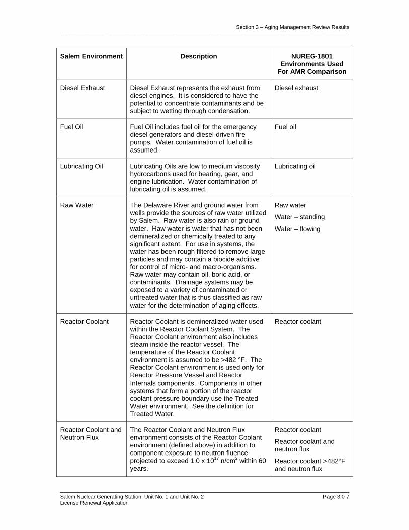
Section 3 – Aging Management Review Results _________________________________________________________________________________________________
________________________________________________________________________ Salem Nuclear Generating Station, Unit No. 1 and Unit No. 2 Page 3.0-7 License Renewal Application
Salem Environment Description NUREG-1801 Environments Used
For AMR Comparison
Diesel Exhaust Diesel Exhaust represents the exhaust from diesel engines. It is considered to have the potential to concentrate contaminants and be subject to wetting through condensation.
Diesel exhaust
Fuel Oil Fuel Oil includes fuel oil for the emergency diesel generators and diesel-driven fire pumps. Water contamination of fuel oil is assumed.
Fuel oil
Lubricating Oil Lubricating Oils are low to medium viscosity hydrocarbons used for bearing, gear, and engine lubrication. Water contamination of lubricating oil is assumed.
Lubricating oil
Raw Water The Delaware River and ground water from wells provide the sources of raw water utilized by Salem. Raw water is also rain or ground water. Raw water is water that has not been demineralized or chemically treated to any significant extent. For use in systems, the water has been rough filtered to remove large particles and may contain a biocide additive for control of micro- and macro-organisms. Raw water may contain oil, boric acid, or contaminants. Drainage systems may be exposed to a variety of contaminated or untreated water that is thus classified as raw water for the determination of aging effects.
Raw water
Water – standing
Water – flowing
Reactor Coolant Reactor Coolant is demineralized water used within the Reactor Coolant System. The Reactor Coolant environment also includes steam inside the reactor vessel. The temperature of the Reactor Coolant environment is assumed to be >482 °F. The Reactor Coolant environment is used only for Reactor Pressure Vessel and Reactor Internals components. Components in other systems that form a portion of the reactor coolant pressure boundary use the Treated Water environment. See the definition for Treated Water.
Reactor coolant
Reactor Coolant and Neutron Flux
The Reactor Coolant and Neutron Flux environment consists of the Reactor Coolant environment (defined above) in addition to component exposure to neutron fluence projected to exceed 1.0 x 10¹⁷ n/cm2 within 60 years.
Reactor coolant
Reactor coolant and neutron flux
Reactor coolant >482°F and neutron flux

Section 3 – Aging Management Review Results _________________________________________________________________________________________________
________________________________________________________________________ Salem Nuclear Generating Station, Unit No. 1 and Unit No. 2 Page 3.0-8 License Renewal Application
Salem Environment Description NUREG-1801 Environments Used
For AMR Comparison
Steam The Steam environment consists of steam that is subject to chemistry controls set by the Water Chemistry Program.
Secondary feedwater/steam
Steam
Treated water
Treated Borated Water
Treated Borated Water is a controlled water system.
Treated borated water
Treated water
Treated Borated Water >140°F
Treated Borated Water >140 °F is treated water with boric acid in systems above the SCC threshold for stainless steel of 140 °F.
Reactor coolant
Treated borated water
Treated borated water >140 °F
Treated water
Treated Borated Water >482°F
Treated Water with boric acid above thermal embrittlement threshold for Cast Austenitic Stainless Steel (CASS) >482 °F. This environment is identified when applicable for CASS components subject to loss of fracture toughness.
Reactor coolant >482 °F
Treated borated water >482 °F
Treated Water Treated Water is demineralized water or chemically purified water and is the base water for all clean systems. Depending on the system, treated water may require further processing. Treated water may be deaerated and may include additives to protect reactor vessel internal and other reactor system components.
Secondary feedwater/ steam
Treated water
Treated Water >140°F
Treated Water >140 °F is Treated Water that has a temperature greater than 140 °F. This environment is identified when applicable for stainless steel components subject to cracking. Refer to the Treated Water environment definition for further details.
Treated water
Treated water >140 °F (For cracking of stainless steel components)
Treated Water >482°F
Treated Water >482 °F is Treated Water that has a temperature greater than 482 °F This environment is identified when applicable for Cast Austenitic Stainless Steel (CASS) components subject to loss of fracture toughness. Refer to the Treated Water environment definition for further details.
Treated water >482 °F

Section 3 – Aging Management Review Results _________________________________________________________________________________________________
________________________________________________________________________ Salem Nuclear Generating Station, Unit No. 1 and Unit No. 2 Page 3.0-9 License Renewal Application
Table 3.0-2 – Salem External Service Environments
Salem Environment Description NUREG-1801 Environments Used
For AMR Comparison
Adverse Local Environment
The Adverse Local Environment represents conditions with excessive heat, radiation, moisture, or voltage, sometimes in the presence of oxygen. The effect can be concentrated or applicable to a general plant area.
Adverse localized environment
Air – Indoor Air - Indoor consists of air environments that are in indoor locations and are sheltered/protected from weather. Humidity levels up to 100 percent are assumed and the surfaces of components in this environment may be wet. Additionally, this environment may contain aggressive chemical species including oxygen, halides, sulfates, or other aggressive corrosive substances that can influence the nature, rate, and severity of corrosion effects. It is assumed that these contaminants can concentrate to levels that will promote corrosive effects because of factors such as cyclic (wet-dry) condensation, contaminated insulation, accidental contamination, or leakage areas.
Air – indoor uncontrolled
Air – indoor uncontrolled or air - outdoor
Air with metal temperature up to 550°F
Air with reactor coolant leakage
System temperature up to 644°F (applies to closure bolting)
Soil (applies to structural cracking due to settlement)
Various
Air – Outdoor Air – Outdoor is atmospheric air with a temperature °F range of –34 °F to 110 °F and a relative humidity range of 10% to 100%. This environment is subject to periodic wetting and wind.
Air – outdoor
Soil (applies to structural cracking due to settlement)
System temperature up to 550°F (applies to closure bolting)
Air with Borated Water Leakage
This environment is applicable to components located in the vicinity of systems containing borated water, including reactor coolant with temperatures above or below the dew point. The borated water from leakage is considered to be untreated due to the potential for water contamination at the surface.
Air – indoor uncontrolled
Air with borated water leakage
Air with reactor coolant leakage

Section 3 – Aging Management Review Results _________________________________________________________________________________________________
________________________________________________________________________ Salem Nuclear Generating Station, Unit No. 1 and Unit No. 2 Page 3.0-10 License Renewal Application
Salem Environment Description NUREG-1801 Environments Used
For AMR Comparison
Air with Steam or Water Leakage
Air with steam or water leakage is air and untreated steam or water leakage on indoor or outdoor systems with temperatures above or below the dew point. For Salem, this environment is assumed inside containment where leakage has occurred from brackish water systems.
Air with steam or water leakage
Air – indoor uncontrolled
Concrete Concrete is used for components that are embedded in concrete.
Concrete
Groundwater/soil Groundwater is the water beneath the surface that can be collected with wells, tunnels, or drainage galleries, or that flows naturally to the earth's surface via seeps or springs. Soil is a mixture of inorganic materials produced by the weathering of rocks and clays, and organic material produced by the decomposition of vegetation. Voids containing air and moisture occupy ~50% of the soil volume. Concrete subjected to a groundwater/soil environment can be vulnerable to an increase in porosity and permeability, cracking, loss of material (spalling, scaling)/ aggressive chemical attack.
Groundwater/soil
Soil
Soil Soil is used for components that are buried in soil.
Soil
Water-flowing Water that is refreshed, thus having larger impact on leaching; this can be rainwater, raw water, groundwater, or flowing water under a foundation.
Water-flowing
Soil (applies to structural cracking due to settlement)
Water-standing Water that is stagnant and unrefreshed, thus possibly resulting in an increased ionic strength of solution up to saturation.
Groundwater/soil
Soil (applies to structural cracking due to settlement)

Section 3 – Aging Management Review Results _________________________________________________________________________________________________________
_________________________________________________________________________________________________________ Salem Nuclear Generating Station, Unit No. 1 and Unit No. 2 Page 3.1-1 License Renewal Application
3.1 AGING MANAGEMENT OF REACTOR VESSEL, INTERNALS, AND REACTOR COOLANT SYSTEM
3.1.1 INTRODUCTION
This section provides the results of the aging management review for those components identified in Section 2.3.1, Reactor Vessel, Internals, and Reactor Coolant System, as being subject to aging management review. The systems, or portions of systems, which are addressed in this section are described in the indicated sections. • Reactor Coolant System (2.3.1.1)
• Reactor Vessel (2.3.1.2)
• Reactor Vessel Internals (2.3.1.3)
• Steam Generators (2.3.1.4)
3.1.2 RESULTS
The following tables summarize the results of the aging management review for Reactor Vessel, Internals and Reactor Coolant System: Table 3.1.2-1 Summary of Aging Management Evaluation – Reactor Coolant System Table 3.1.2-2 Summary of Aging Management Evaluation – Reactor Vessel Table 3.1.2-3 Summary of Aging Management Evaluation – Reactor Vessel Internals Table 3.1.2-4 Summary of Aging Management Evaluation – Steam Generators
3.1.2.1 Materials, Environments, Aging Effects Requiring Management And Aging Management Programs
3.1.2.1.1 Reactor Coolant System
Materials
The materials of construction for the Reactor Coolant System components are:
• Carbon and Low Alloy Steel Bolting
• Carbon or Low Alloy Steel with Stainless Steel Cladding
• Carbon Steel
• Cast Austenitic Stainless Steel (CASS)
• Copper Alloy with less than 15% Zinc
• Glass
• Stainless Steel
• Stainless Steel Bolting

Section 3 – Aging Management Review Results _________________________________________________________________________________________________________
_________________________________________________________________________________________________________ Salem Nuclear Generating Station, Unit No. 1 and Unit No. 2 Page 3.1-2 License Renewal Application
Environments
The Reactor Coolant System components are exposed to the following
environments:
• Air - Indoor
• Air with Borated Water Leakage
• Air with Steam or Water Leakage
• Air/Gas - Dry
• Lubricating Oil
• Reactor Coolant
• Treated Water
Aging Effects Requiring Management
The following aging effects associated with the Reactor Coolant System components require management: • Cracking/Cyclic Loading
• Cracking/Stress Corrosion Cracking, Thermal and Mechanical Loading
• Cumulative Fatigue Damage/Fatigue
• Loss of Fracture Toughness/Thermal Aging Embrittlement
• Loss of Material/Boric Acid Corrosion
• Loss of Material/General, Pitting, Crevice, and Microbiologically Influenced
Corrosion
• Loss of Preload/Thermal Effects, Gasket Creep, and Self-Loosening
Aging Management Programs
The following aging management programs manage the aging effects for the Reactor Coolant System components: • ASME Section XI Inservice Inspection, Subsections IWB, IWC, and IWD
(B.2.1.1)
• Bolting Integrity (B.2.1.9)
• Boric Acid Corrosion (B.2.1.4)
• External Surfaces Monitoring (B.2.1.24)
• Lubricating Oil Analysis (B.2.1.27)
• One-Time Inspection (B.2.1.20)

Section 3 – Aging Management Review Results _________________________________________________________________________________________________________
_________________________________________________________________________________________________________ Salem Nuclear Generating Station, Unit No. 1 and Unit No. 2 Page 3.1-3 License Renewal Application
• One-Time Inspection of ASME Code Class 1 Small Bore-Piping (B.2.1.23)
• Periodic Inspection (B.2.2.2)
• Thermal Aging Embrittlement of Cast Austenitic Stainless Steel (CASS)
(B.2.1.6)
• TLAA
• Water Chemistry (B.2.1.2)
Table 3.1.2-1, Summary of Aging Management Evaluation – Reactor Coolant System summarizes the results of the aging management review for the Reactor Coolant System.
3.1.2.1.2 Reactor Vessel
Materials
The materials of construction for the Reactor Vessel components are: • Carbon and Low Alloy Steel Bolting
• Carbon or Low Alloy Steel with Stainless Steel Cladding
• Carbon Steel
• High Strength Low Alloy Steel Bolting with Yield Strength of 150 ksi or
Greater
• Low Alloy Steel
• Nickel Alloy
• Stainless Steel
• Stainless Steel Bolting
Environments
The Reactor Vessel components are exposed to the following environments: • Air - Indoor
• Air with Borated Water Leakage
• Reactor Coolant
• Reactor Coolant and Neutron Flux

Section 3 – Aging Management Review Results _________________________________________________________________________________________________________
_________________________________________________________________________________________________________ Salem Nuclear Generating Station, Unit No. 1 and Unit No. 2 Page 3.1-4 License Renewal Application
Aging Effects Requiring Management
The following aging effects associated with the Reactor Vessel components require management: • Cracking/Stress Corrosion Cracking, Thermal and Mechanical Loading
• Cumulative Fatigue Damage/Fatigue
• Loss of Fracture Toughness/Neutron Irradiation Embrittlement
• Loss of Material/Boric Acid Corrosion
• Loss of Material/General, Pitting and Crevice Corrosion
• Loss of Material/Wear
• Loss of Preload/Thermal Effects, Gasket Creep, and Self-Loosening
Aging Management Programs
The following aging management programs manage the aging effects for the Reactor Vessel components: • ASME Section XI Inservice Inspection, Subsections IWB, IWC, and IWD
(B.2.1.1)
• Bolting Integrity (B.2.1.9)
• Boric Acid Corrosion (B.2.1.4)
• External Surfaces Monitoring (B.2.1.24)
• Nickel Alloy Aging Management Program (B.2.2.6)
• Nickel-Alloy Penetration Nozzles Welded to the Upper Reactor Vessel
Closure Heads of Pressurized Water Reactors (B.2.1.5)
• Reactor Head Closure Studs (B.2.1.3)
• Reactor Vessel Surveillance (B.2.1.19)
• TLAA
• Water Chemistry (B.2.1.2)
Table 3.1.2-2, Summary of Aging Management Evaluation – Reactor Vessel summarizes the results of the aging management review for the Reactor Vessel.
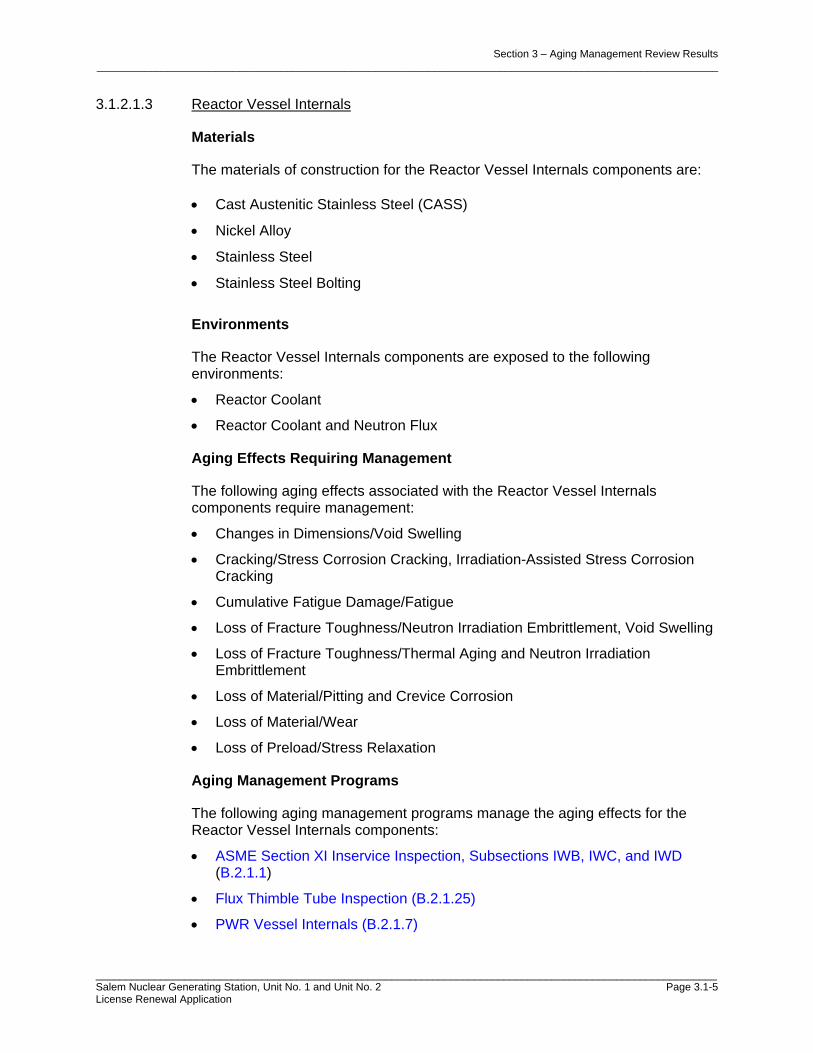
Section 3 – Aging Management Review Results _________________________________________________________________________________________________________
_________________________________________________________________________________________________________ Salem Nuclear Generating Station, Unit No. 1 and Unit No. 2 Page 3.1-5 License Renewal Application
3.1.2.1.3 Reactor Vessel Internals
Materials
The materials of construction for the Reactor Vessel Internals components are: • Cast Austenitic Stainless Steel (CASS)
• Nickel Alloy
• Stainless Steel
• Stainless Steel Bolting
Environments
The Reactor Vessel Internals components are exposed to the following environments:
• Reactor Coolant
• Reactor Coolant and Neutron Flux
Aging Effects Requiring Management
The following aging effects associated with the Reactor Vessel Internals components require management:
• Changes in Dimensions/Void Swelling
• Cracking/Stress Corrosion Cracking, Irradiation-Assisted Stress Corrosion Cracking
• Cumulative Fatigue Damage/Fatigue
• Loss of Fracture Toughness/Neutron Irradiation Embrittlement, Void Swelling
• Loss of Fracture Toughness/Thermal Aging and Neutron Irradiation Embrittlement
• Loss of Material/Pitting and Crevice Corrosion
• Loss of Material/Wear
• Loss of Preload/Stress Relaxation
Aging Management Programs
The following aging management programs manage the aging effects for the Reactor Vessel Internals components:
• ASME Section XI Inservice Inspection, Subsections IWB, IWC, and IWD (B.2.1.1)
• Flux Thimble Tube Inspection (B.2.1.25)
• PWR Vessel Internals (B.2.1.7)

Section 3 – Aging Management Review Results _________________________________________________________________________________________________________
_________________________________________________________________________________________________________ Salem Nuclear Generating Station, Unit No. 1 and Unit No. 2 Page 3.1-6 License Renewal Application
• TLAA
• Water Chemistry (B.2.1.2)
Table 3.1.2-3, Summary of Aging Management Evaluation – Reactor Vessel Internals summarizes the results of the aging management review for the Reactor Vessel Internals.
3.1.2.1.4 Steam Generators
Materials
The materials of construction for the Steam Generator components are:
• Carbon and Low Alloy Steel Bolting
• Carbon or Low Alloy Steel with Nickel Alloy Cladding
• Carbon or Low Alloy Steel with Stainless Steel Cladding
• Carbon Steel
• Low Alloy Steel
• Nickel Alloy
• Stainless Steel
Environments
The Steam Generator components are exposed to the following environments:
• Air - Indoor
• Air with Borated Water Leakage
• Air with Steam or Water Leakage
• Reactor Coolant
• Steam
• Treated Water
• Treated Water > 140 F
Aging Effects Requiring Management
The following aging effects associated with the Steam Generator components require management:
• Cracking/Outer Diameter Stress Corrosion, and Stress Corrosion Cracking
• Cumulative Fatigue Damage/Fatigue
• Loss of Material/Boric Acid Corrosion
• Loss of Material/Erosion, General, Pitting and Crevice Corrosion
• Loss of Material/Fretting and Wear

Section 3 – Aging Management Review Results _________________________________________________________________________________________________________
_________________________________________________________________________________________________________ Salem Nuclear Generating Station, Unit No. 1 and Unit No. 2 Page 3.1-7 License Renewal Application
• Loss of Preload/Thermal Effects, Gasket Creep, and Self-Loosening
• Reduction of Heat Transfer/Fouling
• Wall Thinning/Flow Accelerated Corrosion
Aging Management Programs
The following aging management programs manage the aging effects for the Steam Generator components:
• ASME Section XI Inservice Inspection, Subsections IWB, IWC, and IWD (B.2.1.1)
• Bolting Integrity (B.2.1.9)
• Boric Acid Corrosion (B.2.1.4)
• External Surfaces Monitoring (B.2.1.24)
• Flow-Accelerated Corrosion (B.2.1.8)
• Nickel Alloy Aging Management Program (B.2.2.6)
• One-Time Inspection (B.2.1.20)
• Steam Generator Tube Integrity (B.2.1.10)
• TLAA
• Water Chemistry (B.2.1.2)
Table 3.1.2-4, Summary of Aging Management Evaluation – Steam Generators summarizes the results of the aging management review for the Steam Generators. The aging management review was performed for the new steam generators.
3.1.2.2 AMR Results for Which Further Evaluation is Recommended by the GALL Report
NUREG-1801 provides the basis for identifying those programs that warrant further evaluation by the reviewer in the license renewal application. For the Reactor Vessel, Internals, and Reactor Coolant System, those programs are addressed in the following subsections.
3.1.2.2.1 Cumulative Fatigue Damage
Fatigue is a time-limited aging analysis (TLAA) as defined in 10 CFR 54.3. TLAAs are required to be evaluated in accordance with 10 CFR 54.21(c)(1). The evaluation of metal fatigue as a TLAA for the Auxiliary Feedwater System, Chemical & Volume Control System, Component Cooling System, Main Condensate and Feedwater System, Reactor Coolant System, Reactor Vessel, Reactor Vessel Internals, Residual Heat Removal System, Safety Injection System, Sampling System, and Steam Generators is discussed in Section 4.3.
Section 3 – Aging Management Review Results _________________________________________________________________________________________________________
_________________________________________________________________________________________________________ Salem Nuclear Generating Station, Unit No. 1 and Unit No. 2 Page 3.1-8 License Renewal Application
Item Numbers 3.1.1-1, 3.1.1-2, 3.1.1-3, and 3.1.1-4 are applicable to BWRs only and are not used for Salem.
3.1.2.2.2 Loss of Material due to General, Pitting, and Crevice Corrosion
1. Loss of material due to general, pitting, and crevice corrosion could occur in the steel PWR steam generator shell assembly exposed to secondary feedwater and steam. Loss of material due to general, pitting, and crevice corrosion could also occur for the steel top head enclosure (without cladding) top head nozzles [vent, top head spray or reactor core isolation cooling (RCIC), and spare] exposed to reactor coolant. The existing program relies on control of reactor water chemistry to mitigate corrosion. However, control of water chemistry does not preclude loss of material due to pitting and crevice corrosion at locations of stagnant flow conditions. Therefore, the effectiveness of the chemistry control program should be verified to ensure that corrosion is not occurring. The GALL Report recommends further evaluation of programs to verify the effectiveness of the chemistry control program. A one-time inspection of select components at susceptible locations is an acceptable method to determine whether an aging effect is not occurring or an aging effect is progressing very slowly such that the component’s intended function will be maintained during the period of extended operation.
Salem will implement a Steam Generator Tube Integrity program, B.2.1.10, for susceptible locations to verify the effectiveness of the Water Chemistry program, B.2.1.2, to manage the loss of material due to general, pitting and crevice corrosion in the steel steam generator tube bundle tie rod assembly and anti-vibration bars exposed to treated water in the Steam Generators. The Steam Generator Tube Integrity and Water Chemistry programs are described in Appendix B. Item Number 3.1.1-11 is applicable to BWRs only and is not used for Salem. Item Number 3.1.1-13 is applicable to BWRs only and is not used for Salem. Item Number 3.1.1-14 and 3.1.1-15 are applicable to BWRs only and are not used for Salem.
2. Loss of material due to general, pitting, and crevice corrosion could occur in the steel PWR steam generator upper and lower shell and transition cone exposed to secondary feedwater and steam. The existing program relies on control of chemistry to mitigate corrosion and In-service Inspection (ISI) to detect loss of material. The extent and schedule of the existing steam generator inspections are designed to ensure that flaws cannot attain a depth sufficient to threaten the integrity of the welds. However, according to NRC Information Notice (IN) 90-04, the program may not be sufficient to detect pitting and crevice corrosion, if general and pitting corrosion of the shell is known to exist. The GALL Report recommends augmented inspection to manage this aging effect. Furthermore, the GALL Report clarifies that this issue is limited to Westinghouse Model 44 and 51 Steam Generators where a high stress region exists at the shell to transition cone weld. Acceptance criteria are described in Branch Technical Position RLSB-1.

Section 3 – Aging Management Review Results _________________________________________________________________________________________________________
_________________________________________________________________________________________________________ Salem Nuclear Generating Station, Unit No. 1 and Unit No. 2 Page 3.1-9 License Renewal Application
Salem will implement an ASME Section XI Inservice Inspection, Subsections IWB, IWC, and IWD program, B.2.1.1, for susceptible locations to verify the effectiveness of the Water Chemistry program, B.2.1.2, to manage the loss of material due to general, pitting and crevice corrosion in steel steam generator components (secondary manways and covers, tubesheets, upper head, upper shell, conical shell, lower shell), piping components and connections, and main feedwater and main steam nozzles exposed to steam and treated water in the Steam Generators. The ASME Section XI Inservice Inspection, Subsections IWB, IWC, and IWD and Water Chemistry programs are described in Appendix B. Salem will implement a Steam Generator Tube Integrity program, B.2.1.10, for susceptible locations to verify the effectiveness of the Water Chemistry program, B.2.1.2, to manage the loss of material due to general, pitting and crevice corrosion in the steel steam generator feedwater ring and supports exposed to treated water in the Steam Generators. The Steam Generator Tube Integrity and Water Chemistry programs are described in Appendix B. Salem does not have Westinghouse Model 44 or 51 type Steam Generators.
3.1.2.2.3 Loss of Fracture Toughness due to Neutron Irradiation Embrittlement
1. Neutron irradiation embrittlement is a TLAA to be evaluated for the period of extended operation for all ferritic materials that have a neutron fluence greater than 1017 n/cm2 (E >1 MeV) at the end of the license renewal term. Certain aspects of neutron irradiation embrittlement are TLAAs as defined in 10 CFR 54.3. TLAAs are required to be evaluated in accordance with 10 CFR 54.21(c)(1). This TLAA is addressed separately in Section 4.2, “Reactor Vessel Neutron Embrittlement Analysis,” of the SRP-LR. Neutron irradiation embrittlement is a TLAA as defined in 10 CFR 54.3. TLAAs are required to be evaluated in accordance with 10 CFR 54.21(c)(1). The evaluation of neutron irradiation embrittlement as a TLAA for the Reactor Vessel is discussed in Section 4.2.
2. Loss of fracture toughness due to neutron irradiation embrittlement could occur in BWR and PWR reactor vessel beltline shell, nozzle, and welds exposed to reactor coolant and neutron flux. A reactor vessel materials surveillance program monitors neutron irradiation embrittlement of the reactor vessel. Reactor vessel surveillance program is plant-specific, depending on matters such as the composition of limiting materials, availability of surveillance capsules, and projected fluence levels. In accordance with 10 CFR Part 50, Appendix H, an applicant is required to submit its proposed withdrawal schedule for approval prior to implementation. Untested capsules placed in storage must be maintained for future insertion. Thus, further staff evaluation is required for license renewal. Specific recommendations for an acceptable AMP are provided in Chapter XI, Section M31 of the GALL Report. Salem will implement a Reactor Vessel Surveillance program, B.2.1.19, to manage the loss of fracture toughness due to neutron irradiation embrittlement in the steel with stainless steel cladding reactor vessel shells exposed to reactor coolant and neutron flux. The Reactor Vessel Surveillance program provides
Section 3 – Aging Management Review Results _________________________________________________________________________________________________________
_________________________________________________________________________________________________________ Salem Nuclear Generating Station, Unit No. 1 and Unit No. 2 Page 3.1-10 License Renewal Application
sufficient material data and dosimetry to monitor irradiation embrittlement at the end of the period of extended operation and to determine the need for operating restrictions on the inlet temperature, neutron spectrum, and neutron flux. The Reactor Vessel Surveillance program is described in Appendix B.
3.1.2.2.4 Cracking due to Stress Corrosion Cracking (SCC) and Intergranular Stress
Corrosion Cracking (IGSCC)
1. Item Number 3.1.1-19 is applicable to BWRs only and is not used for Salem.
2. Item Number 3.1.1-20 is applicable to BWRs only and is not used for Salem.
3.1.2.2.5 Crack Growth due to Cyclic Loading
Crack growth due to cyclic loading could occur in reactor vessel shell forgings clad with stainless steel using a high-heat-input welding process. Growth of intergranular separations (underclad cracks) in the heat affected zone under austenitic stainless steel cladding is a TLAA to be evaluated for the period of extended operation for all the SA 508-Cl 2 forgings where the cladding was deposited with a high heat input welding process. The methodology for evaluating the underclad flaw should be consistent with the current well-established flaw evaluation procedure and criterion in the ASME Section XI Code. See the SRP-LR, Section 4.7, “Other Plant-Specific Time-Limited Aging Analysis,” for generic guidance for meeting the requirements of 10 CFR 54.21(c). Item Number 3.1.1-21 is not applicable for Salem. The Reactor Vessel Shell is not fabricated of SA 508-Cl 2 forgings clad with stainless steel using a high-heat-input welding process.
3.1.2.2.6 Loss of Fracture Toughness due to Neutron Irradiation Embrittlement and Void Swelling
Loss of fracture toughness due to neutron irradiation embrittlement and void swelling could occur in stainless steel and nickel alloy reactor vessel internals components exposed to reactor coolant and neutron flux. The GALL Report recommends no further aging management review if the applicant provides a commitment in the FSAR Supplement to (1) participate in the industry programs for investigating and managing aging effects on reactor internals; (2) evaluate and implement the results of the industry programs as applicable to the reactor internals; and (3) upon completion of these programs, but not less than 24 months before entering the period of extended operation, submit an inspection plan for reactor internals to the NRC for review and approval. As described in the PWR Vessel Internals program, B.2.1.7, Salem will implement a commitment in the UFSAR Supplement for PWR Vessel Internals to manage the aging effects of loss of fracture toughness due to neutron irradiation embrittlement and void swelling in stainless steel and nickel alloy reactor vessel components exposed to reactor coolant and neutron flux. Salem provides in the UFSAR Supplement a commitment to: (1) participate in the industry programs for investigating and managing aging effects on reactor internals; (2) evaluate and implement the results of the industry programs as applicable to the reactor internals; and (3) upon

Section 3 – Aging Management Review Results _________________________________________________________________________________________________________
_________________________________________________________________________________________________________ Salem Nuclear Generating Station, Unit No. 1 and Unit No. 2 Page 3.1-11 License Renewal Application
completion of these programs, but not less than 24 months before entering the period of extended operation, submit an inspection plan for reactor internals to the NRC for review and approval. The UFSAR Supplement Commitment for PWR Vessel Internals is described in Appendix A. The PWR Vessel Internals program is described in Appendix B.
3.1.2.2.7 Cracking due to Stress Corrosion Cracking
1. Cracking due to SCC could occur in the PWR stainless steel reactor vessel flange leak detection lines and bottom-mounted instrument guide tubes exposed to reactor coolant. The GALL Report recommends further evaluation to ensure that these aging effects are adequately managed. The GALL Report recommends that a plant specific AMP be evaluated to ensure that this aging effect is adequately managed. Acceptance criteria are described in Branch Technical Position RLSB-1. Salem will implement the ASME Section XI Inservice Inspection program, Subsections IWB, IWC, and IWD, B.2.1.1 to manage cracking due to stress corrosion cracking in the stainless steel reactor vessel flange leak detection lines exposed to reactor coolant. The ASME Section XI Inservice Inspection program, Subsections IWB, IWC, and IWD, B.2.1.1, relies on VT-2 examinations to identify and evaluate the degradation of stainless steel reactor vessel flange leak detection lines to ensure that there is no loss of intended function. The Salem bottom-mounted instrument guide tubes are nickel alloy and are included with line item 3.1.1-31. The ASME Section XI Inservice Inspection program, Subsections IWB, IWC, and IWD program is described in Appendix B.
2. Cracking due to SCC could occur in Class 1 PWR cast austenitic stainless steel (CASS) reactor coolant system piping, piping components, and piping elements exposed to reactor coolant. The existing program relies on control of water chemistry to mitigate SCC; however SCC could occur for CASS components that do not meet the NUREG-0313 guidelines with regard to ferrite and carbon content. The GALL Report recommends further evaluation of a plant specific program for these components to ensure that this aging effect is adequately managed. Acceptance criteria are described in Branch Technical Position RLSB-1. Salem will implement the Water Chemistry program, B.2.1.2, to manage cracking due to stress corrosion cracking in the Class 1 cast austenitic stainless steel (CASS) reactor coolant system valve bodies exposed to reactor coolant. Salem will implement the Thermal Aging Embrittlement of Cast Austenitic Stainless Steel (CASS) program, B.2.1.6, and the Water Chemistry program, B.2.1.2, to manage cracking due to stress corrosion cracking in the Class 1 cast austenitic stainless steel (CASS) reactor coolant system components exposed to reactor coolant. The Thermal Aging Embrittlement of Cast Austenitic Stainless Steel (CASS) program includes condition monitoring activities of reactor coolant system CASS components susceptible to thermal aging embrittlement to ensure that there is no loss of intended function. The Thermal Aging Embrittlement of Cast Austenitic Stainless Steel (CASS) program and the Water Chemistry program are described in Appendix B.

Section 3 – Aging Management Review Results _________________________________________________________________________________________________________
_________________________________________________________________________________________________________ Salem Nuclear Generating Station, Unit No. 1 and Unit No. 2 Page 3.1-12 License Renewal Application
3.1.2.2.8 Cracking due to Cyclic Loading
1. Item Number 3.1.1-25 is applicable to BWRs only and is not used for Salem.
2. Item Number 3.1.1-26 is applicable to BWRs only and is not used for Salem.
3.1.2.2.9 Loss of Preload due to Stress Relaxation
Loss of preload due to stress relaxation could occur in stainless steel and nickel alloy PWR reactor vessel internals screws, bolts, tie rods, and hold-down springs exposed to reactor coolant. The GALL Report recommends no further aging management review if the applicant provides a commitment in the FSAR Supplement to (1) participate in the industry programs for investigating and managing aging effects on reactor internals; (2) evaluate and implement the results of the industry programs as applicable to the reactor internals; and (3) upon completion of these programs, but not less than 24 months before entering the period of extended operation, submit an inspection plan for reactor internals to the NRC for review and approval. As described in the PWR Vessel Internals program, B.2.1.7, Salem will implement a commitment in the UFSAR Supplement for PWR Vessel Internals to manage the aging effects of loss of preload due to stress relaxation in stainless steel and nickel alloy reactor vessel components exposed to reactor coolant and neutron flux. Salem provides in the UFSAR Supplement a commitment to: (1) participate in the industry programs for investigating and managing aging effects on reactor internals; (2) evaluate and implement the results of the industry programs as applicable to the reactor internals; and (3) upon completion of these programs, but not less than 24 months before entering the period of extended operation, submit an inspection plan for reactor internals to the NRC for review and approval. The UFSAR Supplement Commitment for PWR Vessel Internals is described in Appendix A. The PWR Vessel Internals program is described in Appendix B.
3.1.2.2.10 Loss of Material due to Erosion
Loss of material due to erosion could occur in steel steam generator feedwater impingement plates and supports exposed to secondary feedwater. The GALL Report recommends further evaluation of a plant-specific AMP to ensure that this aging effect is adequately managed. Acceptance criteria are described in Branch Technical Position RLSB-1. Item Number 3.1.1-28 is not applicable to Salem. Steel steam generator feedwater impingement plates and supports do not exist in the Salem Steam Generators.
3.1.2.2.11 Cracking due to Flow-Induced Vibration
Item Number 3.1.1-29 is applicable to BWRs only and is not used for Salem.

Section 3 – Aging Management Review Results _________________________________________________________________________________________________________
_________________________________________________________________________________________________________ Salem Nuclear Generating Station, Unit No. 1 and Unit No. 2 Page 3.1-13 License Renewal Application
3.1.2.2.12 Cracking due to Stress Corrosion Cracking and Irradiation-Assisted Stress Corrosion Cracking (IASCC)
Cracking due to SCC and IASCC could occur in PWR stainless steel reactor internals exposed to reactor coolant. The existing program relies on control of water chemistry to mitigate these effects. The GALL Report recommends no further aging management review if the applicant provides a commitment in the FSAR Supplement to (1) participate in the industry programs for investigating and managing aging effects on reactor internals; (2) evaluate and implement the results of the industry programs as applicable to the reactor internals; and (3) upon completion of these programs, but not less than 24 months before entering the period of extended operation, submit an inspection plan for reactor internals to the NRC for review and approval. As described in the PWR Vessel Internals program, B.2.1.7, Salem will implement a commitment in the UFSAR Supplement for PWR Vessel Internals and implement the Water Chemistry program, B.2.1.2, to manage the aging effects of cracking due to stress corrosion cracking and irradiation-assisted stress corrosion cracking in stainless steel reactor vessel internals components exposed to reactor coolant and neutron flux. Salem provides in the UFSAR Supplement a commitment to: (1) participate in the industry programs for investigating and managing aging effects on reactor internals; (2) evaluate and implement the results of the industry programs as applicable to the reactor internals; and (3) upon completion of these programs, but not less than 24 months before entering the period of extended operation, submit an inspection plan for reactor internals to the NRC for review and approval. The UFSAR Supplement Commitment for PWR Vessel Internals is described in Appendix A. The PWR Vessel Internals program and the Water Chemistry program are described in Appendix B.
3.1.2.2.13 Cracking due to Primary Water Stress Corrosion Cracking (PWSCC)
Cracking due to PWSCC could occur in PWR components made of nickel alloy and steel with nickel alloy cladding, including reactor coolant pressure boundary components and penetrations inside the RCS such as pressurizer heater sheathes and sleeves, nozzles, and other internal components. With the exception of reactor vessel upper head nozzles and penetrations, the GALL Report recommends ASME Section XI ISI (for Class 1 components) and control of water chemistry. For nickel alloy components, no further aging management review is necessary if the applicant complies with applicable NRC Orders and provides a commitment in the FSAR supplement to implement applicable (1) Bulletins and Generic Letters and (2) staff-accepted industry guidelines. Salem will implement the ASME Section XI Inservice Inspection program, Subsections IWB, IWC, and IWD, B.2.1.1, the Nickel Alloy Aging Management program, B.2.2.6, and the Water Chemistry program, B.2.1.2, to manage the aging effects of cracking due to stress corrosion cracking in nickel alloy piping components, piping elements, bottom-mounted instrument guide tubes, penetrations, nozzles, safe ends, and welds; exposed to reactor coolant in the Reactor Vessel and Steam Generators. Salem complies with applicable NRC Orders and provides a commitment in the UFSAR Supplement to implement applicable (1) Bulletins and Generic Letters and (2) staff-accepted industry guidelines. The UFSAR supplement

Section 3 – Aging Management Review Results _________________________________________________________________________________________________________
_________________________________________________________________________________________________________ Salem Nuclear Generating Station, Unit No. 1 and Unit No. 2 Page 3.1-14 License Renewal Application
commitment is described in Appendix A. The ASME Section XI Inservice Inspection, Subsections IWB, IWC and IWD, Nickel Alloy Aging Management and Water Chemistry programs are described in Appendix B.
3.1.2.2.14 Wall Thinning due to Flow-Accelerated Corrosion
Wall thinning due to flow-accelerated corrosion could occur in steel feedwater inlet rings and supports. The GALL Report references NRC IN 91-19, "Steam Generator Feedwater Distribution Piping Damage," for evidence of flow accelerated corrosion in steam generators and recommends that a plant-specific AMP be evaluated because existing programs may not be capable of mitigating or detecting wall thinning due to flow-accelerated corrosion. Acceptance criteria are described in Branch Technical Position RLSB-1. Salem will implement a Steam Generator Tube Integrity program, B.2.1.10, for susceptible locations to manage wall thinning due to flow-accelerated corrosion in the steel steam generator feedwater inlet ring and supports exposed to treated water in the Steam Generators. The Steam Generator Tube Integrity program implements a number of industry guidelines and incorporates a balance of prevention, inspection, evaluation, repair, and leakage monitoring measures to assure that existing environmental conditions are not causing wall thinning that could result in a loss of component intended function. The Steam Generator Tube Integrity program is described in Appendix B.
3.1.2.2.15 Changes in Dimensions due to Void Swelling
Changes in dimensions due to void swelling could occur in stainless steel and nickel alloy PWR reactor internal components exposed to reactor coolant. The GALL Report recommends no further aging management review if the applicant provides a commitment in the FSAR Supplement to (1) participate in the industry programs for investigating and managing aging effects on reactor internals; (2) evaluate and implement the results of the industry programs as applicable to the reactor internals; and (3) upon completion of these programs, but not less than 24 months before entering the period of extended operation, submit an inspection plan for reactor internals to the NRC for review and approval. As described in the PWR Vessel Internals program, B.2.1.7, Salem will implement a commitment in the UFSAR Supplement for PWR Vessel Internals to manage the aging effects of changes in dimensions due to void swelling in stainless steel and nickel alloy reactor vessel internals components exposed to reactor coolant and neutron flux. Salem provides in the UFSAR Supplement a commitment to: (1) participate in the industry programs for investigating and managing aging effects on reactor internals; (2) evaluate and implement the results of the industry programs as applicable to the reactor internals; and (3) upon completion of these programs, but not less than 24 months before entering the period of extended operation, submit an inspection plan for reactor internals to the NRC for review and approval. The UFSAR Supplement Commitment for PWR Vessel Internals is described in Appendix A. The PWR Vessel Internals program is described in Appendix B.

Section 3 – Aging Management Review Results _________________________________________________________________________________________________________
_________________________________________________________________________________________________________ Salem Nuclear Generating Station, Unit No. 1 and Unit No. 2 Page 3.1-15 License Renewal Application
3.1.2.2.16 Cracking due to Stress Corrosion Cracking and Primary Water Stress Corrosion Cracking
1. Cracking due to SCC could occur on the primary coolant side of PWR steel
steam generator upper and lower heads, tubesheets, and tube-to-tube sheet welds made or clad with stainless steel. Cracking due to PWSCC could occur on the primary coolant side of PWR steel steam generator upper and lower heads, tubesheets, and tube-to-tube sheet welds made or clad with nickel alloy. The GALL Report recommends ASME Section XI ISI and control of water chemistry to manage this aging and recommends no further aging management review for PWSCC of nickel alloy if the applicant complies with applicable NRC Orders and provides a commitment in the FSAR supplement to implement applicable (1) Bulletins and Generic Letters and (2) staff-accepted industry guidelines. Salem will implement the ASME Section XI Inservice Inspection program, Subsections IWB, IWC, and IWD, B.2.1.1, and the Water Chemistry program, B.2.1.2, to manage cracking due to stress corrosion cracking in stainless steel reactor control rod drive head penetration pressure housings. The ASME Section XI Inservice Inspection, Subsections IWB, IWC and IWD and Water Chemistry programs are described in Appendix B. Item Number 3.1.1-35 is not applicable. Salem does not have Once-Through Steam Generators and therefore does not have the components associated with the Once-Through Steam Generators.
2. Cracking due to SCC could occur on stainless steel pressurizer spray heads. Cracking due to PWSCC could occur on nickel-alloy pressurizer spray heads. The existing program relies on control of water chemistry to mitigate this aging effect. The GALL Report recommends one-time inspection to confirm that cracking is not occurring. For nickel alloy welded spray heads, the GALL Report recommends no further aging management review if the applicant complies with applicable NRC Orders and provide a commitment in the FSAR supplement to implement applicable (1) Bulletins and Generic Letters and (2) staff-accepted industry guidelines. Salem will implement the One-Time Inspection program, B.2.1.20, to verify the effectiveness of the Water Chemistry program, B.2.1.2, to manage cracking due to stress corrosion cracking in the stainless steel pressurizer spray head exposed to reactor coolant. The One-Time Inspection and Water Chemistry programs are described in Appendix B.
3.1.2.2.17 Cracking due to Stress Corrosion Cracking, Primary Water Stress Corrosion
Cracking, and Irradiation-Assisted Stress Corrosion Cracking
Cracking due to stress corrosion cracking (SCC), primary water stress corrosion cracking (PWSCC), and irradiation assisted stress corrosion cracking (IASCC) could occur in PWR stainless steel and nickel alloy reactor vessel internals components. The existing program relies on control of water chemistry to mitigate these effects. However, the existing program should be augmented to manage these aging effects for reactor vessel internals components. The GALL Report recommends no further

Section 3 – Aging Management Review Results _________________________________________________________________________________________________________
_________________________________________________________________________________________________________ Salem Nuclear Generating Station, Unit No. 1 and Unit No. 2 Page 3.1-16 License Renewal Application
aging management review if the applicant provides a commitment in the FSAR Supplement to (1) participate in the industry programs for investigating and managing aging effects on reactor internals; (2) evaluate and implement the results of the industry programs as applicable to the reactor internals; and (3) upon completion of these programs, but not less than 24 months before entering the period of extended operation, submit an inspection plan for reactor internals to the NRC for review and approval. As described in the PWR Vessel Internals program, B.2.1.7, Salem will implement a commitment in the UFSAR Supplement for PWR Vessel Internals and implement the Water Chemistry program, B.2.1.2, to manage the aging effects of cracking due to stress corrosion cracking and irradiation-assisted stress corrosion cracking in stainless steel and nickel alloy reactor vessel internals components exposed to reactor coolant and neutron flux. Salem provides in the UFSAR Supplement a commitment to: (1) participate in the industry programs for investigating and managing aging effects on reactor internals; (2) evaluate and implement the results of the industry programs as applicable to the reactor internals; and (3) upon completion of these programs, but not less than 24 months before entering the period of extended operation, submit an inspection plan for reactor internals to the NRC for review and approval. The UFSAR Supplement Commitment for PWR Vessel Internals is described in Appendix A. The PWR Vessel Internals and the Water Chemistry programs are described in Appendix B.
3.1.2.2.18 Quality Assurance for Aging Management of Nonsafety-Related Components
QA provisions applicable to License Renewal are discussed in Section B.1.3.
3.1.2.3 Time-Limited Aging Analyses
The time-limited aging analyses identified below are associated with the Reactor Vessel, Internals, and Reactor Coolant System components: • Section 4.2, Reactor Vessel Neutron Embrittlement • Section 4.3, Metal Fatigue of Piping and Components • Section 4.4, Other Plant-Specific Analyses
3.1.3 CONCLUSION
The Reactor Vessel, Internals, and Reactor Coolant System piping, fittings and components that are subject to aging management review have been identified in accordance with the requirements of 10 CFR 54.4. The aging management programs selected to manage aging effects for the Reactor Vessel, Internals, and Reactor Coolant System components are identified in the summaries in Section 3.1.2.1 above.
A description of these aging management programs is provided in Appendix B, along with the demonstration that the identified aging effects will be managed for the period of extended operation.
Therefore, based on the conclusions provided in Appendix B, the effects of aging associated with the Reactor Vessel, Internals, and Reactor Coolant System components will be adequately managed so that there is reasonable assurance that the intended
Section 3 – Aging Management Review Results _________________________________________________________________________________________________________
_________________________________________________________________________________________________________ Salem Nuclear Generating Station, Unit No. 1 and Unit No. 2 Page 3.1-17 License Renewal Application
function(s) will be maintained consistent with the current licensing basis during the period of extended operation.
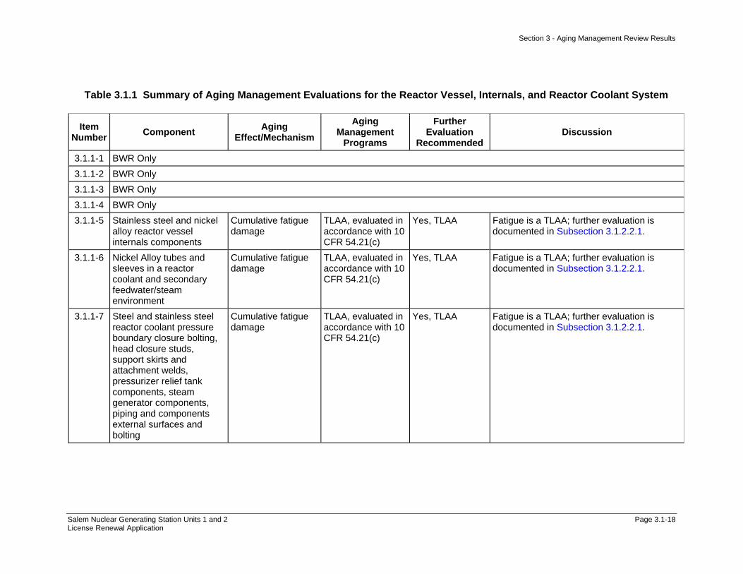
Section 3 - Aging Management Review Results
Salem Nuclear Generating Station Units 1 and 2 Page 3.1-18 License Renewal Application
Table 3.1.1 Summary of Aging Management Evaluations for the Reactor Vessel, Internals, and Reactor Coolant System
Item Number Component Aging
Effect/Mechanism Aging
Management Programs
Further Evaluation
Recommended Discussion
3.1.1-1 BWR Only 3.1.1-2 BWR Only 3.1.1-3 BWR Only 3.1.1-4 BWR Only 3.1.1-5 Stainless steel and nickel
alloy reactor vessel internals components
Cumulative fatigue damage
TLAA, evaluated in accordance with 10 CFR 54.21(c)
Yes, TLAA Fatigue is a TLAA; further evaluation is documented in Subsection 3.1.2.2.1.
3.1.1-6 Nickel Alloy tubes and sleeves in a reactor coolant and secondary feedwater/steam environment
Cumulative fatigue damage
TLAA, evaluated in accordance with 10 CFR 54.21(c)
Yes, TLAA Fatigue is a TLAA; further evaluation is documented in Subsection 3.1.2.2.1.
3.1.1-7 Steel and stainless steel reactor coolant pressure boundary closure bolting, head closure studs, support skirts and attachment welds, pressurizer relief tank components, steam generator components, piping and components external surfaces and bolting
Cumulative fatigue damage
TLAA, evaluated in accordance with 10 CFR 54.21(c)
Yes, TLAA Fatigue is a TLAA; further evaluation is documented in Subsection 3.1.2.2.1.

Section 3 - Aging Management Review Results
Salem Nuclear Generating Station Units 1 and 2 Page 3.1-19 License Renewal Application
Table 3.1.1 Summary of Aging Management Evaluations for the Reactor Vessel, Internals, and Reactor Coolant System
Item Number Component Aging
Effect/Mechanism Aging
Management Programs
Further Evaluation
Recommended Discussion
3.1.1-8 Steel; stainless steel; and nickel-alloy reactor coolant pressure boundary piping, piping components, piping elements; flanges; nozzles and safe ends; pressurizer vessel shell heads and welds; heater sheaths and sleeves; penetrations; and thermal sleeves
Cumulative fatigue damage
TLAA, evaluated in accordance with 10 CFR 54.21(c) and environmental effects are to be addressed for Class 1 components
Yes, TLAA Fatigue is a TLAA; further evaluation is documented in Subsection 3.1.2.2.1.
3.1.1-9 Steel; stainless steel; steel with nickel-alloy or stainless steel cladding; nickel-alloy reactor vessel components: flanges; nozzles; penetrations; pressure housings; safe ends; thermal sleeves; vessel shells, heads and welds
Cumulative fatigue damage
TLAA, evaluated in accordance with 10 CFR 54.21(c) and environmental effects are to be addressed for Class 1 components
Yes, TLAA Fatigue is a TLAA; further evaluation is documented in Subsection 3.1.2.2.1.
3.1.1-10 Steel; stainless steel; steel with nickel-alloy or stainless steel cladding; nickel-alloy steam generator components (flanges; penetrations; nozzles; safe ends, lower heads and welds)
Cumulative fatigue damage
TLAA, evaluated in accordance with 10 CFR 54.21(c) and environmental effects are to be addressed for Class 1 components
Yes, TLAA Fatigue is a TLAA; further evaluation is documented in Subsection 3.1.2.2.1.
3.1.1-11 BWR Only

Section 3 - Aging Management Review Results
Salem Nuclear Generating Station Units 1 and 2 Page 3.1-20 License Renewal Application
Table 3.1.1 Summary of Aging Management Evaluations for the Reactor Vessel, Internals, and Reactor Coolant System
Item Number Component Aging
Effect/Mechanism Aging
Management Programs
Further Evaluation
Recommended Discussion
3.1.1-12 Steel steam generator shell assembly exposed to secondary feedwater and steam
Loss of material due to general, pitting and crevice corrosion
Water Chemistry and One-Time Inspection
Yes, detection of aging effects is to be evaluated
Consistent with NUREG-1801. The Water Chemistry program, B.2.1.2, will be used to manage the loss of material due to general, pitting and crevice corrosion in the steel steam generator tube bundle tie rod assembly and anti-vibration bars exposed to treated water. Components in the Steam Generators system have been aligned to this item number based on material, environment and aging effect. The Steam Generator Tube Integrity program, B.2.1.10, will be substituted to verify the effectiveness of the Water Chemistry program, B.2.1.2, to manage the loss of material due to general, pitting and crevice corrosion in the steel steam generators exposed to treated water for this system. See Subsection 3.1.2.2.2.1.
3.1.1-13 BWR Only 3.1.1-14 BWR Only 3.1.1-15 BWR Only

Section 3 - Aging Management Review Results
Salem Nuclear Generating Station Units 1 and 2 Page 3.1-21 License Renewal Application
Table 3.1.1 Summary of Aging Management Evaluations for the Reactor Vessel, Internals, and Reactor Coolant System
Item Number Component Aging
Effect/Mechanism Aging
Management Programs
Further Evaluation
Recommended Discussion
3.1.1-16 Steel steam generator upper and lower shell and transition cone exposed to secondary feedwater and steam
Loss of material due to general, pitting and crevice corrosion
Inservice Inspection (IWB, IWC, and IWD), and Water Chemistry and, for Westinghouse Model 44 and 51 S/G, if general and pitting corrosion of the shell is known to exist, additional inspection procedures are to be developed.
Yes, detection of aging effects is to be evaluated
Consistent with NUREG-1801. The ASME Section XI Inservice Inspection, Subsections IWB, IWC, and IWD program, B.2.1.1, will be used to verify the effectiveness of the Water Chemistry program, B.2.1.2, to manage the loss of material due to general, pitting and crevice corrosion in the steel steam generator components (secondary manways and covers, tubesheets, upper head, upper shell, conical shell, lower shell), piping components and connections, and main feedwater and main steam nozzles exposed to steam and treated water in the Steam Generators. Components in the Steam Generators system have been aligned to this item number based on material, environment and aging effect. The Steam Generator Tube Integrity program, B.2.1.10, will be substituted to verify the effectiveness of the Water Chemistry program, B.2.1.2, to manage the loss of material due to general, pitting and crevice corrosion in the steel steam generator feedwater inlet ring and supports exposed to treated water for this system. See subsection 3.1.2.2.2.2.

Section 3 - Aging Management Review Results
Salem Nuclear Generating Station Units 1 and 2 Page 3.1-22 License Renewal Application
Table 3.1.1 Summary of Aging Management Evaluations for the Reactor Vessel, Internals, and Reactor Coolant System
Item Number Component Aging
Effect/Mechanism Aging
Management Programs
Further Evaluation
Recommended Discussion
3.1.1-17 Steel (with or without stainless steel cladding) reactor vessel beltline shell, nozzles, and welds
Loss of fracture toughness due to neutron irradiation embrittlement
TLAA, evaluated in accordance with Appendix G of 10 CFR Part 50 and RG 1.99. The applicant may choose to demonstrate that the materials of the nozzles are not controlling for the TLAA evaluations.
Yes, TLAA Loss of fracture toughness due to neutron irradiation embrittlement is a TLAA; further evaluation is documented in Subsection 3.1.2.2.3.1.
3.1.1-18 Steel (with or without stainless steel cladding) reactor vessel beltline shell, nozzles, and welds; safety injection nozzles
Loss of fracture toughness due to neutron irradiation embrittlement
Reactor Vessel Surveillance
Yes, plant specific
Consistent with NUREG-1801. The Reactor Vessel Surveillance program, B.2.1.19, will be used to manage the loss of fracture toughness due to neutron irradiation embrittlement in the steel with stainless steel cladding reactor vessel shell exposed to reactor coolant and neutron flux. See Subsection 3.1.2.2.3.2.
3.1.1-19 BWR Only 3.1.1-20 BWR Only 3.1.1-21 Reactor vessel shell
fabricated of SA508-Cl 2 forgings clad with stainless steel using a high-heat-input welding process
Crack growth due to cyclic loading
TLAA Yes, TLAA Not Applicable. See Subsection 3.1.2.2.5.

Section 3 - Aging Management Review Results
Salem Nuclear Generating Station Units 1 and 2 Page 3.1-23 License Renewal Application
Table 3.1.1 Summary of Aging Management Evaluations for the Reactor Vessel, Internals, and Reactor Coolant System
Item Number Component Aging
Effect/Mechanism Aging
Management Programs
Further Evaluation
Recommended Discussion
3.1.1-22 Stainless steel and nickel alloy reactor vessel internals components exposed to reactor coolant and neutron flux
Loss of fracture toughness due to neutron irradiation embrittlement, void swelling
FSAR supplement commitment to (1) participate in industry RVI aging programs (2) implement applicable results (3) submit for NRC approval > 24 months before the extended period an RVI inspection plan based on industry recommendation.
No, but licensee commitment to be confirmed
Consistent with NUREG-1801. The UFSAR Supplement Commitment for PWR Vessel Internals as described in the PWR Vessel Internals program, B.2.1.7, will be used to manage the loss of fracture toughness due to neutron irradiation embrittlement, void swelling in stainless steel and nickel alloy reactor vessel internals components exposed to reactor coolant and neutron flux. See Subsection 3.1.2.2.6.
3.1.1-23 Stainless steel reactor vessel closure head flange leak detection line and bottom-mounted instrument guide tubes
Cracking due to stress corrosion cracking
A plant-specific aging management program is to be evaluated.
Yes, plant specific
The ASME Section XI Inservice Inspection program, Subsections IWB, IWC, and IWD, B.2.1.1 will be used to manage cracking due to stress corrosion cracking in the stainless steel reactor vessel closure head flange leak detection line. See Subsection 3.1.2.2.7.1.

Section 3 - Aging Management Review Results
Salem Nuclear Generating Station Units 1 and 2 Page 3.1-24 License Renewal Application
Table 3.1.1 Summary of Aging Management Evaluations for the Reactor Vessel, Internals, and Reactor Coolant System
Item Number Component Aging
Effect/Mechanism Aging
Management Programs
Further Evaluation
Recommended Discussion
3.1.1-24 Class 1 cast austenitic stainless steel piping, piping components, and piping elements exposed to reactor coolant
Cracking due to stress corrosion cracking
Water Chemistry and, for CASS components that do not meet the NUREG-0313 guidelines, a plant specific aging management program
Yes, plant specific
Consistent with NUREG-1801. Salem will implement the Water Chemistry program, B.2.1.2, to manage cracking due to stress corrosion cracking in the Class 1 cast austenitic stainless steel (CASS) reactor coolant system valve bodies exposed to reactor coolant. Components in the Reactor Coolant System have been aligned to this item number based on material, environment and aging effect. The Thermal Aging Embrittlement of Cast Austenitic Stainless Steel (CASS) program, B.2.1.6, will be added, along with the Water Chemistry program, B.2.1.2, to manage cracking due to stress corrosion cracking in the Class 1 cast austenitic stainless steel (CASS) reactor coolant system components exposed to reactor coolant. See Subsection 3.1.2.2.7.2.
3.1.1-25 BWR Only 3.1.1-26 BWR Only

Section 3 - Aging Management Review Results
Salem Nuclear Generating Station Units 1 and 2 Page 3.1-25 License Renewal Application
Table 3.1.1 Summary of Aging Management Evaluations for the Reactor Vessel, Internals, and Reactor Coolant System
Item Number Component Aging
Effect/Mechanism Aging
Management Programs
Further Evaluation
Recommended Discussion
3.1.1-27 Stainless steel and nickel alloy reactor vessel internals screws, bolts, tie rods, and hold-down springs
Loss of preload due to stress relaxation
FSAR supplement commitment to (1) participate in industry RVI aging programs (2) implement applicable results (3) submit for NRC approval > 24 months before the extended period an RVI inspection plan based on industry recommendation.
No, but licensee commitment to be confirmed
Consistent with NUREG-1801. The UFSAR Supplement Commitment for PWR Vessel Internals as described in the PWR Vessel Internals program, B.2.1.7, will be used to manage the loss of preload due to stress relaxation in stainless steel and nickel alloy reactor vessel internals components exposed to reactor coolant and neutron flux. See Subsection 3.1.2.2.9.
3.1.1-28 Steel steam generator feedwater impingement plate and support exposed to secondary feedwater
Loss of material due to erosion
A plant-specific aging management program is to be evaluated.
Yes, plant specific
Not applicable. See Subsection 3.1.2.2.10.
3.1.1-29 BWR Only

Section 3 - Aging Management Review Results
Salem Nuclear Generating Station Units 1 and 2 Page 3.1-26 License Renewal Application
Table 3.1.1 Summary of Aging Management Evaluations for the Reactor Vessel, Internals, and Reactor Coolant System
Item Number Component Aging
Effect/Mechanism Aging
Management Programs
Further Evaluation
Recommended Discussion
3.1.1-30 Stainless steel reactor vessel internals components (e.g., Upper internals assembly, RCCA guide tube assemblies, Baffle/former assembly, Lower internal assembly, shroud assemblies, Plenum cover and plenum cylinder, Upper grid assembly, Control rod guide tube (CRGT) assembly, Core support shield assembly, Core barrel assembly, Lower grid assembly, Flow distributor assembly, Thermal shield, Instrumentation support structures)
Cracking due to stress corrosion cracking, irradiation-assisted stress corrosion cracking
Water Chemistry and FSAR supplement commitment to (1) participate in industry RVI aging programs (2) implement applicable results (3) submit for NRC approval > 24 months before the extended period an RVI inspection plan based on industry recommendation.
No, but licensee commitment needs to be confirmed
Consistent with NUREG-1801. The UFSAR Supplement Commitment for PWR Vessel Internals as described in the PWR Vessel Internals program, B.2.1.7, and the Water Chemistry program, B.2.1.2, will be used to manage cracking due to stress corrosion cracking, irradiation-assisted stress corrosion cracking in stainless steel reactor vessel internals components exposed to reactor coolant and neutron flux. See Subsection 3.1.2.2.12.
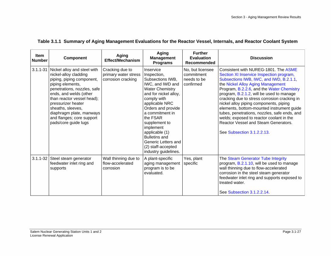
Section 3 - Aging Management Review Results
Salem Nuclear Generating Station Units 1 and 2 Page 3.1-27 License Renewal Application
Table 3.1.1 Summary of Aging Management Evaluations for the Reactor Vessel, Internals, and Reactor Coolant System
Item Number Component Aging
Effect/Mechanism Aging
Management Programs
Further Evaluation
Recommended Discussion
3.1.1-31 Nickel alloy and steel with nickel-alloy cladding piping, piping component, piping elements, penetrations, nozzles, safe ends, and welds (other than reactor vessel head); pressurizer heater sheaths, sleeves, diaphragm plate, manways and flanges; core support pads/core guide lugs
Cracking due to primary water stress corrosion cracking
Inservice Inspection, Subsections IWB, IWC, and IWD and Water Chemistry and for nickel alloy, comply with applicable NRC Orders and provide a commitment in the FSAR supplement to implement applicable (1) Bulletins and Generic Letters and (2) staff-accepted industry guidelines.
No, but licensee commitment needs to be confirmed
Consistent with NUREG-1801. The ASME Section XI Inservice Inspection program, Subsections IWB, IWC, and IWD, B.2.1.1, the Nickel Alloy Aging Management Program, B.2.2.6, and the Water Chemistry program, B.2.1.2, will be used to manage cracking due to stress corrosion cracking in nickel alloy piping components, piping elements, bottom-mounted instrument guide tubes, penetrations, nozzles, safe ends, and welds; exposed to reactor coolant in the Reactor Vessel and Steam Generators. See Subsection 3.1.2.2.13.
3.1.1-32 Steel steam generator feedwater inlet ring and supports
Wall thinning due to flow-accelerated corrosion
A plant-specific aging management program is to be evaluated.
Yes, plant specific
The Steam Generator Tube Integrity program, B.2.1.10, will be used to manage wall thinning due to flow-accelerated corrosion in the steel steam generator feedwater inlet ring and supports exposed to treated water. See Subsection 3.1.2.2.14.
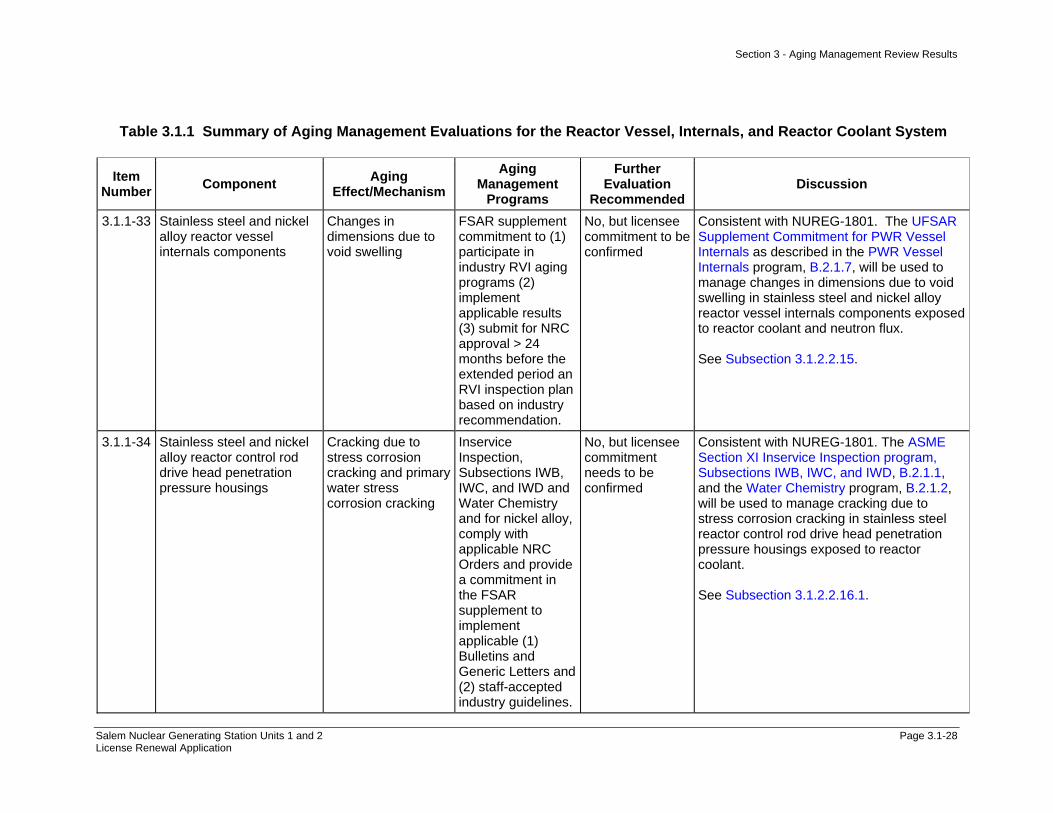
Section 3 - Aging Management Review Results
Salem Nuclear Generating Station Units 1 and 2 Page 3.1-28 License Renewal Application
Table 3.1.1 Summary of Aging Management Evaluations for the Reactor Vessel, Internals, and Reactor Coolant System
Item Number Component Aging
Effect/Mechanism Aging
Management Programs
Further Evaluation
Recommended Discussion
3.1.1-33 Stainless steel and nickel alloy reactor vessel internals components
Changes in dimensions due to void swelling
FSAR supplement commitment to (1) participate in industry RVI aging programs (2) implement applicable results (3) submit for NRC approval > 24 months before the extended period an RVI inspection plan based on industry recommendation.
No, but licensee commitment to be confirmed
Consistent with NUREG-1801. The UFSAR Supplement Commitment for PWR Vessel Internals as described in the PWR Vessel Internals program, B.2.1.7, will be used to manage changes in dimensions due to void swelling in stainless steel and nickel alloy reactor vessel internals components exposed to reactor coolant and neutron flux. See Subsection 3.1.2.2.15.
3.1.1-34 Stainless steel and nickel alloy reactor control rod drive head penetration pressure housings
Cracking due to stress corrosion cracking and primary water stress corrosion cracking
Inservice Inspection, Subsections IWB, IWC, and IWD and Water Chemistry and for nickel alloy, comply with applicable NRC Orders and provide a commitment in the FSAR supplement to implement applicable (1) Bulletins and Generic Letters and (2) staff-accepted industry guidelines.
No, but licensee commitment needs to be confirmed
Consistent with NUREG-1801. The ASME Section XI Inservice Inspection program, Subsections IWB, IWC, and IWD, B.2.1.1, and the Water Chemistry program, B.2.1.2, will be used to manage cracking due to stress corrosion cracking in stainless steel reactor control rod drive head penetration pressure housings exposed to reactor coolant. See Subsection 3.1.2.2.16.1.

Section 3 - Aging Management Review Results
Salem Nuclear Generating Station Units 1 and 2 Page 3.1-29 License Renewal Application
Table 3.1.1 Summary of Aging Management Evaluations for the Reactor Vessel, Internals, and Reactor Coolant System
Item Number Component Aging
Effect/Mechanism Aging
Management Programs
Further Evaluation
Recommended Discussion
3.1.1-35 Steel with stainless steel or nickel alloy cladding primary side components; steam generator upper and lower heads, tubesheets and tube-to-tube sheet welds
Cracking due to stress corrosion cracking and primary water stress corrosion cracking
Inservice Inspection, Subsections IWB, IWC, and IWD and Water Chemistry and for nickel alloy, comply with applicable NRC Orders and provide a commitment in the FSAR supplement to implement applicable (1) Bulletins and Generic Letters and (2) staff-accepted industry guidelines.
No, but licensee commitment needs to be confirmed
Not Applicable. Salem does not have Once-Through Steam Generators and therefore does not have the components associated with the Once-Through Steam Generators. See Subsection 3.1.2.2.16.1.
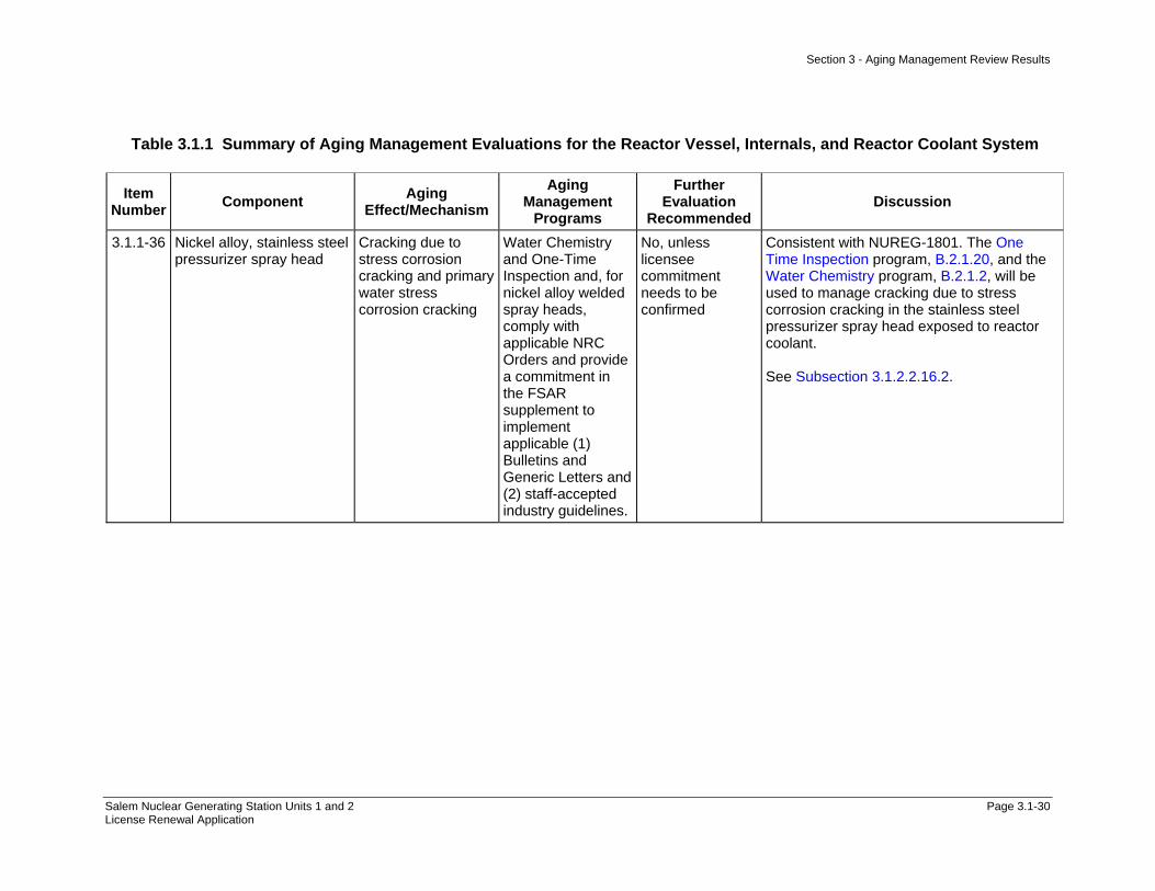
Section 3 - Aging Management Review Results
Salem Nuclear Generating Station Units 1 and 2 Page 3.1-30 License Renewal Application
Table 3.1.1 Summary of Aging Management Evaluations for the Reactor Vessel, Internals, and Reactor Coolant System
Item Number Component Aging
Effect/Mechanism Aging
Management Programs
Further Evaluation
Recommended Discussion
3.1.1-36 Nickel alloy, stainless steel pressurizer spray head
Cracking due to stress corrosion cracking and primary water stress corrosion cracking
Water Chemistry and One-Time Inspection and, for nickel alloy welded spray heads, comply with applicable NRC Orders and provide a commitment in the FSAR supplement to implement applicable (1) Bulletins and Generic Letters and (2) staff-accepted industry guidelines.
No, unless licensee commitment needs to be confirmed
Consistent with NUREG-1801. The One Time Inspection program, B.2.1.20, and the Water Chemistry program, B.2.1.2, will be used to manage cracking due to stress corrosion cracking in the stainless steel pressurizer spray head exposed to reactor coolant. See Subsection 3.1.2.2.16.2.
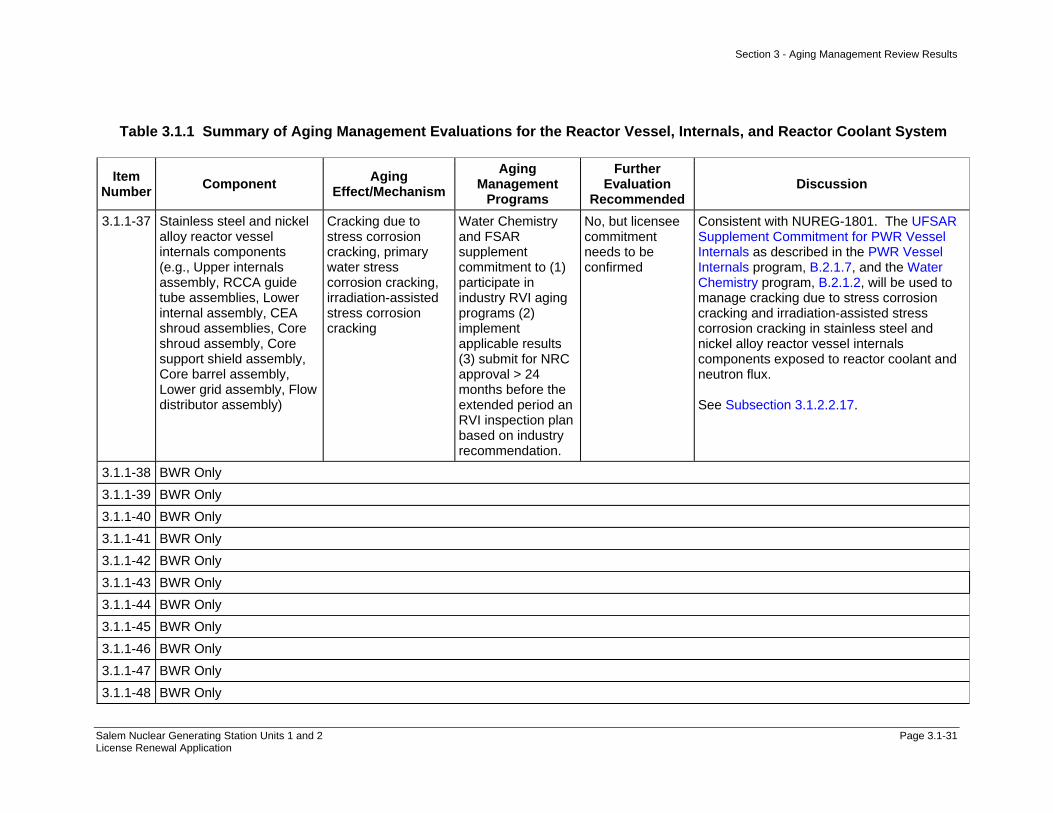
Section 3 - Aging Management Review Results
Salem Nuclear Generating Station Units 1 and 2 Page 3.1-31 License Renewal Application
Table 3.1.1 Summary of Aging Management Evaluations for the Reactor Vessel, Internals, and Reactor Coolant System
Item Number Component Aging
Effect/Mechanism Aging
Management Programs
Further Evaluation
Recommended Discussion
3.1.1-37 Stainless steel and nickel alloy reactor vessel internals components (e.g., Upper internals assembly, RCCA guide tube assemblies, Lower internal assembly, CEA shroud assemblies, Core shroud assembly, Core support shield assembly, Core barrel assembly, Lower grid assembly, Flow distributor assembly)
Cracking due to stress corrosion cracking, primary water stress corrosion cracking, irradiation-assisted stress corrosion cracking
Water Chemistry and FSAR supplement commitment to (1) participate in industry RVI aging programs (2) implement applicable results (3) submit for NRC approval > 24 months before the extended period an RVI inspection plan based on industry recommendation.
No, but licensee commitment needs to be confirmed
Consistent with NUREG-1801. The UFSAR Supplement Commitment for PWR Vessel Internals as described in the PWR Vessel Internals program, B.2.1.7, and the Water Chemistry program, B.2.1.2, will be used to manage cracking due to stress corrosion cracking and irradiation-assisted stress corrosion cracking in stainless steel and nickel alloy reactor vessel internals components exposed to reactor coolant and neutron flux. See Subsection 3.1.2.2.17.
3.1.1-38 BWR Only 3.1.1-39 BWR Only 3.1.1-40 BWR Only 3.1.1-41 BWR Only 3.1.1-42 BWR Only 3.1.1-43 BWR Only 3.1.1-44 BWR Only 3.1.1-45 BWR Only 3.1.1-46 BWR Only 3.1.1-47 BWR Only 3.1.1-48 BWR Only
Section 3 - Aging Management Review Results
Salem Nuclear Generating Station Units 1 and 2 Page 3.1-32 License Renewal Application
Table 3.1.1 Summary of Aging Management Evaluations for the Reactor Vessel, Internals, and Reactor Coolant System
Item Number Component Aging
Effect/Mechanism Aging
Management Programs
Further Evaluation
Recommended Discussion
3.1.1-49 BWR Only 3.1.1-50 BWR Only 3.1.1-51 BWR Only

Section 3 - Aging Management Review Results
Salem Nuclear Generating Station Units 1 and 2 Page 3.1-33 License Renewal Application
Table 3.1.1 Summary of Aging Management Evaluations for the Reactor Vessel, Internals, and Reactor Coolant System
Item Number Component Aging
Effect/Mechanism Aging
Management Programs
Further Evaluation
Recommended Discussion
3.1.1-52 Steel and stainless steel reactor coolant pressure boundary (RCPB) pump and valve closure bolting, manway and holding bolting, flange bolting, and closure bolting in high-pressure and high-temperature systems
Cracking due to stress corrosion cracking, loss of material due to wear, loss of preload due to thermal effects, gasket creep, and self-loosening
Bolting Integrity No Consistent with NUREG-1801 with exceptions. The Bolting Integrity program, B.2.1.9, will be used to manage the loss of preload due to thermal effects, gasket creep, and self-loosening in steel and stainless steel bolting exposed to indoor air or outdoor air in the Chemical & Volume Control System, Compressed Air System, Containment Building Ventilation System, Cranes and Hoists, Fire Protection System, Fuel Handling & Fuel Storage System, Heating Water and Heating Steam System, Main Condensate and Feedwater System, Non-radioactive Drain System, Radioactive Drain System, Radwaste System, Reactor Coolant System, Reactor Vessel, Residual Heat Removal System, Safety Injection System, Service Water System, and Steam Generators. Exceptions apply to the NUREG-1801 recommendations for the Bolting Integrity program implementation. Components in the Cranes and Hoists and Fuel Handling & Fuel Storage systems have been aligned to this item number based on material, environment and aging effect. The Inspection of Overhead Heavy Load and Light Load (Related to Refueling) Handling Systems program, B.2.1.13, will be substituted to manage the loss of preload due to self-loosening in steel and stainless steel bolting exposed to indoor air and outdoor air in the Cranes and Hoists and the Fuel Handling & Fuel Storage System.

Section 3 - Aging Management Review Results
Salem Nuclear Generating Station Units 1 and 2 Page 3.1-34 License Renewal Application
Table 3.1.1 Summary of Aging Management Evaluations for the Reactor Vessel, Internals, and Reactor Coolant System
Item Number Component Aging
Effect/Mechanism Aging
Management Programs
Further Evaluation
Recommended Discussion
3.1.1-53 Steel piping, piping components, and piping elements exposed to closed cycle cooling water
Loss of material due to general, pitting and crevice corrosion
Closed-Cycle Cooling Water System
No Not applicable. There is no steel piping, piping components, or piping elements exposed to closed cycle cooling water in the Reactor Vessel, Internals and Reactor Coolant System.
3.1.1-54 Copper alloy piping, piping components, and piping elements exposed to closed cycle cooling water
Loss of material due to pitting, crevice, and galvanic corrosion
Closed-Cycle Cooling Water System
No Not applicable. There is no copper alloy piping, piping components, or piping elements exposed to closed cycle cooling water in the Reactor Vessel, Internals and Reactor Coolant System.
3.1.1-55 Cast austenitic stainless steel Class 1 pump casings, and valve bodies and bonnets exposed to reactor coolant >250°C (>482°F)
Loss of fracture toughness due to thermal aging embrittlement
Inservice inspection (IWB, IWC, and IWD). Thermal aging susceptibility screening is not necessary, inservice inspection requirements are sufficient for managing these aging effects. ASME Code Case N-481 also provides an alternative for pump casings.
No Consistent with NUREG-1801. The ASME Section XI Inservice Inspection program, Subsections IWB, IWC, and IWD, B.2.1.1, will be used to manage the loss of fracture toughness due to thermal aging embrittlement in cast austenitic stainless steel Class 1 pump casings and valve bodies exposed to reactor coolant in the Chemical & Volume Control and Reactor Coolant Systems.
3.1.1-56 Copper alloy >15% Zn piping, piping components, and piping elements exposed to closed cycle cooling water
Loss of material due to selective leaching
Selective Leaching of Materials
No Not applicable. There is no copper alloy >15% zinc piping, piping components, or piping elements exposed to closed cycle cooling water in the Reactor Vessel, Internals and Reactor Coolant System.

Section 3 - Aging Management Review Results
Salem Nuclear Generating Station Units 1 and 2 Page 3.1-35 License Renewal Application
Table 3.1.1 Summary of Aging Management Evaluations for the Reactor Vessel, Internals, and Reactor Coolant System
Item Number Component Aging
Effect/Mechanism Aging
Management Programs
Further Evaluation
Recommended Discussion
3.1.1-57 Cast austenitic stainless steel Class 1 piping, piping component, and piping elements and control rod drive pressure housings exposed to reactor coolant >250°C (>482°F)
Loss of fracture toughness due to thermal aging embrittlement
Thermal Aging Embrittlement of CASS
No Consistent with NUREG-1801. The Thermal Aging Embrittlement of CASS program, B.2.1.6, will be used to manage the loss of fracture toughness due to thermal aging embrittlement in the cast austenitic stainless steel reactor coolant pressure boundary components exposed to reactor coolant in the Reactor Coolant System.
3.1.1-58 Steel reactor coolant pressure boundary external surfaces exposed to air with borated water leakage
Loss of material due to Boric acid corrosion
Boric Acid Corrosion
No Consistent with NUREG-1801. The Boric Acid Corrosion program, B.2.1.4, will be used to manage the loss of material due to boric acid corrosion on steel reactor coolant pressure boundary external surfaces exposed to air with borated water leakage in the Reactor Coolant System, Reactor Vessel, and Steam Generators.
3.1.1-59 Steel steam generator steam nozzle and safe end, feedwater nozzle and safe end, AFW nozzles and safe ends exposed to secondary feedwater/steam
Wall thinning due to flow-accelerated corrosion
Flow-Accelerated Corrosion
No Consistent with NUREG-1801 with exceptions. The Flow-Accelerated Corrosion program, B.2.1.8, will be used to manage the wall thinning due to flow-accelerated corrosion on steel steam generator steam nozzle and feedwater nozzle (and safe ends) exposed to treated water and steam in the Steam Generators. Exceptions apply to the NUREG-1801 recommendations for the Flow-Accelerated Corrosion program implementation.

Section 3 - Aging Management Review Results
Salem Nuclear Generating Station Units 1 and 2 Page 3.1-36 License Renewal Application
Table 3.1.1 Summary of Aging Management Evaluations for the Reactor Vessel, Internals, and Reactor Coolant System
Item Number Component Aging
Effect/Mechanism Aging
Management Programs
Further Evaluation
Recommended Discussion
3.1.1-60 Stainless steel flux thimble tubes (with or without chrome plating)
Loss of material due to Wear
Flux Thimble Tube Inspection
No Consistent with NUREG-1801. The Flux Thimble Tube Inspection program, B.2.1.25, will be used to manage the loss of material due to wear in the stainless steel flux thimble tubes exposed to reactor coolant and neutron flux in the Reactor Vessel Internals.
3.1.1-61 Stainless steel, steel pressurizer integral support exposed to air with metal temperature up to 288°C (550°F)
Cracking due to cyclic loading
Inservice Inspection (IWB, IWC, and IWD)
No Consistent with NUREG-1801. The ASME Section XI Inservice Inspection program, Subsections IWB, IWC, and IWD, B.2.1.1, will be used to manage cracking due to cyclic loading in the steel pressurizer support exposed to indoor air in the Reactor Coolant System.
3.1.1-62 Stainless steel, steel with stainless steel cladding reactor coolant system cold leg, hot leg, surge line, and spray line piping and fittings exposed to reactor coolant
Cracking due to cyclic loading
Inservice Inspection (IWB, IWC, and IWD)
No Consistent with NUREG-1801. The ASME Section XI Inservice Inspection program, Subsections IWB, IWC, and IWD, B.2.1.1, will be used to manage cracking due to cyclic loading in stainless steel reactor coolant system pressure boundary piping and fittings exposed to reactor coolant in the Reactor Coolant System.
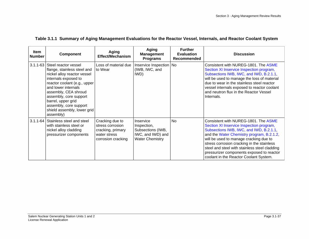
Section 3 - Aging Management Review Results
Salem Nuclear Generating Station Units 1 and 2 Page 3.1-37 License Renewal Application
Table 3.1.1 Summary of Aging Management Evaluations for the Reactor Vessel, Internals, and Reactor Coolant System
Item Number Component Aging
Effect/Mechanism Aging
Management Programs
Further Evaluation
Recommended Discussion
3.1.1-63 Steel reactor vessel flange, stainless steel and nickel alloy reactor vessel internals exposed to reactor coolant (e.g., upper and lower internals assembly, CEA shroud assembly, core support barrel, upper grid assembly, core support shield assembly, lower grid assembly)
Loss of material due to Wear
Inservice Inspection (IWB, IWC, and IWD)
No Consistent with NUREG-1801. The ASME Section XI Inservice Inspection program, Subsections IWB, IWC, and IWD, B.2.1.1, will be used to manage the loss of material due to wear in the stainless steel reactor vessel internals exposed to reactor coolant and neutron flux in the Reactor Vessel Internals.
3.1.1-64 Stainless steel and steel with stainless steel or nickel alloy cladding pressurizer components
Cracking due to stress corrosion cracking, primary water stress corrosion cracking
Inservice Inspection, Subsections (IWB, IWC, and IWD) and Water Chemistry
No Consistent with NUREG-1801. The ASME Section XI Inservice Inspection program, Subsections IWB, IWC, and IWD, B.2.1.1, and the Water Chemistry program, B.2.1.2, will be used to manage cracking due to stress corrosion cracking in the stainless steel and steel with stainless steel cladding pressurizer components exposed to reactor coolant in the Reactor Coolant System.

Section 3 - Aging Management Review Results
Salem Nuclear Generating Station Units 1 and 2 Page 3.1-38 License Renewal Application
Table 3.1.1 Summary of Aging Management Evaluations for the Reactor Vessel, Internals, and Reactor Coolant System
Item Number Component Aging
Effect/Mechanism Aging
Management Programs
Further Evaluation
Recommended Discussion
3.1.1-65 Nickel alloy reactor vessel upper head and control rod drive penetration nozzles, instrument tubes, head vent pipe (top head), and welds
Cracking due to primary water stress corrosion cracking
Inservice Inspection, Subsections (IWB, IWC, and IWD) and Water Chemistry and Nickel-Alloy Penetration Nozzles Welded to the Upper Reactor Vessel Closure Heads of Pressurized Water Reactors
No Consistent with NUREG-1801. The ASME Section XI Inservice Inspection program, Subsections IWB, IWC, and IWD, B.2.1.1, Nickel-Alloy Penetration Nozzles Welded to the Upper Reactor Vessel Closure Heads of Pressurized Water Reactors program, B.2.1.5, and the Water Chemistry program, B.2.1.2, will be used to manage cracking due to stress corrosion cracking in nickel-alloy reactor vessel upper head nozzles and welds exposed to reactor coolant in the Reactor Vessel.
3.1.1-66 Steel steam generator secondary manways and handholds (cover only) exposed to air with leaking secondary-side water and/or steam
Loss of material due to erosion
Inservice Inspection, Subsections (IWB, IWC, and IWD) for Class 2 components
No Not applicable. The steel steam generator secondary manways and handhold covers are not exposed to air with leaking secondary-side water and/or steam. There has been no operating experience at Salem with leaking manways or handholds.
3.1.1-67 Steel with stainless steel or nickel alloy cladding; or stainless steel pressurizer components exposed to reactor coolant
Cracking due to cyclic loading
Inservice Inspection (IWB, IWC, and IWD), and Water Chemistry
No Consistent with NUREG-1801. The ASME Section XI Inservice Inspection program, Subsections IWB, IWC, and IWD, B.2.1.1, and the Water Chemistry program, B.2.1.2, will be used to manage cracking due to cyclic loading in the stainless steel and steel with stainless steel cladding pressurizer components exposed to reactor coolant in the Reactor Coolant System.

Section 3 - Aging Management Review Results
Salem Nuclear Generating Station Units 1 and 2 Page 3.1-39 License Renewal Application
Table 3.1.1 Summary of Aging Management Evaluations for the Reactor Vessel, Internals, and Reactor Coolant System
Item Number Component Aging
Effect/Mechanism Aging
Management Programs
Further Evaluation
Recommended Discussion
3.1.1-68 Stainless steel, steel with stainless steel cladding Class 1 piping, fittings, pump casings, valve bodies, nozzles, safe ends, manways, flanges, CRD housing; pressurizer heater sheaths, sleeves, diaphragm plate; pressurizer relief tank components, reactor coolant system cold leg, hot leg, surge line, and spray line piping and fittings
Cracking due to stress corrosion cracking
Inservice Inspection (IWB, IWC, and IWD), and Water Chemistry
No Consistent with NUREG-1801. The ASME Section XI Inservice Inspection program, Subsections IWB, IWC, and IWD, B.2.1.1, and the Water Chemistry program, B.2.1.2, will be used to manage cracking due to stress corrosion cracking in the stainless steel, steel with stainless steel cladding Class 1 piping, fittings, pump casings, valve bodies, nozzles, safe ends, manways, pressurizer components, and reactor coolant pressure boundary components exposed to reactor coolant and treated water in the Reactor Coolant System, Reactor Vessel, Safety Injection System, and Steam Generators.
3.1.1-69 Stainless steel, nickel alloy safety injection nozzles, safe ends, and associated welds and buttering exposed to reactor coolant
Cracking due to stress corrosion cracking, primary water stress corrosion cracking
Inservice Inspection (IWB, IWC, and IWD), and Water Chemistry
No Consistent with NUREG-1801. The ASME Section XI Inservice Inspection program, Subsections IWB, IWC, and IWD, B.2.1.1, and the Water Chemistry program, B.2.1.2, will be used to manage cracking due to stress corrosion cracking in the stainless steel and steel with stainless steel cladding reactor vessel nozzles, safe ends, welds and reactor vessel head and shell exposed to reactor coolant and neutron flux in the Reactor Vessel.
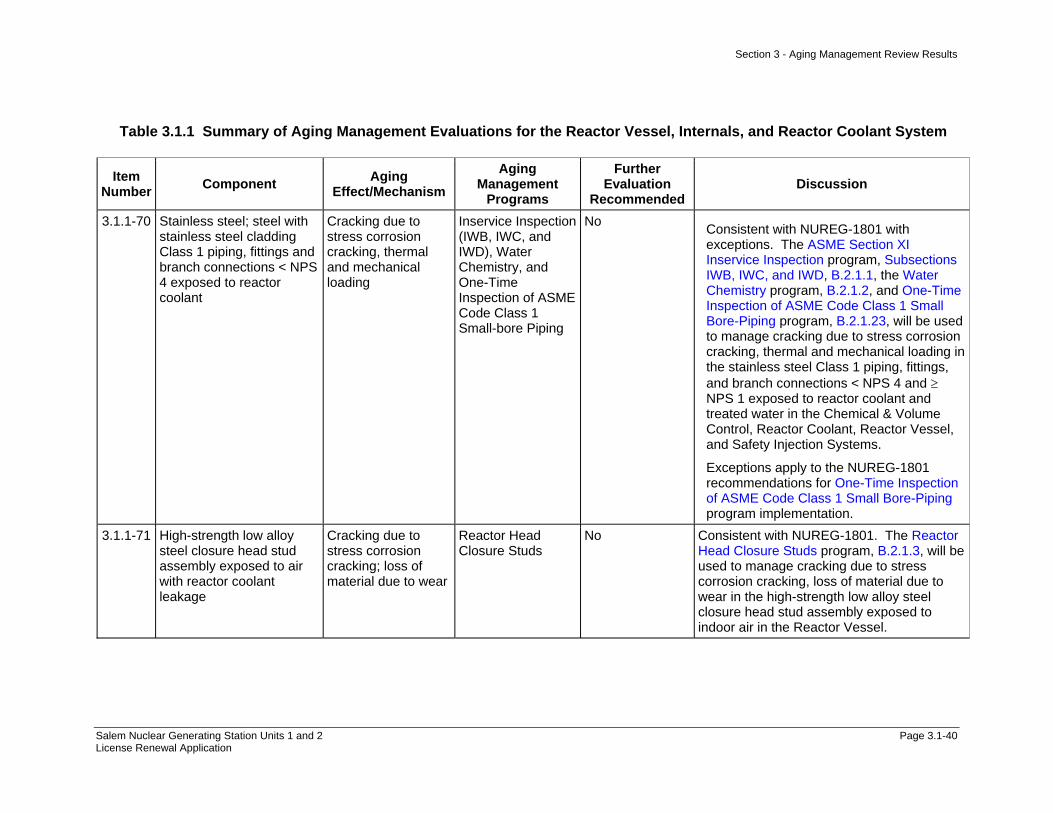
Section 3 - Aging Management Review Results
Salem Nuclear Generating Station Units 1 and 2 Page 3.1-40 License Renewal Application
Table 3.1.1 Summary of Aging Management Evaluations for the Reactor Vessel, Internals, and Reactor Coolant System
Item Number Component Aging
Effect/Mechanism Aging
Management Programs
Further Evaluation
Recommended Discussion
3.1.1-70 Stainless steel; steel with stainless steel cladding Class 1 piping, fittings and branch connections < NPS 4 exposed to reactor coolant
Cracking due to stress corrosion cracking, thermal and mechanical loading
Inservice Inspection (IWB, IWC, and IWD), Water Chemistry, and One-Time Inspection of ASME Code Class 1 Small-bore Piping
No Consistent with NUREG-1801 with exceptions. The ASME Section XI Inservice Inspection program, Subsections IWB, IWC, and IWD, B.2.1.1, the Water Chemistry program, B.2.1.2, and One-Time Inspection of ASME Code Class 1 Small Bore-Piping program, B.2.1.23, will be used to manage cracking due to stress corrosion cracking, thermal and mechanical loading in the stainless steel Class 1 piping, fittings, and branch connections < NPS 4 and ≥ NPS 1 exposed to reactor coolant and treated water in the Chemical & Volume Control, Reactor Coolant, Reactor Vessel, and Safety Injection Systems.
Exceptions apply to the NUREG-1801 recommendations for One-Time Inspection of ASME Code Class 1 Small Bore-Piping program implementation.
3.1.1-71 High-strength low alloy steel closure head stud assembly exposed to air with reactor coolant leakage
Cracking due to stress corrosion cracking; loss of material due to wear
Reactor Head Closure Studs
No Consistent with NUREG-1801. The Reactor Head Closure Studs program, B.2.1.3, will be used to manage cracking due to stress corrosion cracking, loss of material due to wear in the high-strength low alloy steel closure head stud assembly exposed to indoor air in the Reactor Vessel.

Section 3 - Aging Management Review Results
Salem Nuclear Generating Station Units 1 and 2 Page 3.1-41 License Renewal Application
Table 3.1.1 Summary of Aging Management Evaluations for the Reactor Vessel, Internals, and Reactor Coolant System
Item Number Component Aging
Effect/Mechanism Aging
Management Programs
Further Evaluation
Recommended Discussion
3.1.1-72 Nickel alloy steam generator tubes and sleeves exposed to secondary feedwater/ steam
Cracking due to OD stress corrosion cracking and intergranular attack, loss of material due to fretting and wear
Steam Generator Tube Integrity and Water Chemistry
No Consistent with NUREG-1801. The Steam Generator Tube Integrity program, B.2.1.10, and the Water Chemistry program, B.2.1.2, will be used to manage cracking due to OD stress corrosion cracking and inter-granular attack, and loss of material due to fretting and wear in the nickel alloy steam generator tubes and tube plugs exposed to treated water in the Steam Generators.
3.1.1-73 Nickel alloy steam generator tubes, repair sleeves, and tube plugs exposed to reactor coolant
Cracking due to primary water stress corrosion cracking
Steam Generator Tube Integrity and Water Chemistry
No Consistent with NUREG-1801. The Steam Generator Tube Integrity program, B.2.1.10, and the Water Chemistry program, B.2.1.2, will be used to manage cracking due to stress corrosion cracking in the nickel alloy steam generator tubes, tube plugs and steel with nickel alloy cladding tubesheets exposed to reactor coolant in the Steam Generators.
3.1.1-74 Chrome plated steel, stainless steel, nickel alloy steam generator anti-vibration bars exposed to secondary feedwater/ steam
Cracking due to stress corrosion cracking, loss of material due to crevice corrosion and fretting
Steam Generator Tube Integrity and Water Chemistry
No Consistent with NUREG-1801. The Steam Generator Tube Integrity program, B.2.1.10, and the Water Chemistry program, B.2.1.2, will be used to manage cracking due to stress corrosion cracking and loss of material due to crevice corrosion and fretting of the carbon steel (Unit 1 Tube Bundle Tie Rod Assemblies and Anti-Vibration Bars only), nickel alloy and stainless steel tube bundle tie rod assemblies, anti-vibration bars, tubes, tube support plates, and tube plugs exposed to treated water in the Steam Generators.

Section 3 - Aging Management Review Results
Salem Nuclear Generating Station Units 1 and 2 Page 3.1-42 License Renewal Application
Table 3.1.1 Summary of Aging Management Evaluations for the Reactor Vessel, Internals, and Reactor Coolant System
Item Number Component Aging
Effect/Mechanism Aging
Management Programs
Further Evaluation
Recommended Discussion
3.1.1-75 Nickel alloy once-through steam generator tubes exposed to secondary feedwater/ steam
Denting due to corrosion of carbon steel tube support plate
Steam Generator Tube Integrity and Water Chemistry
No Not applicable. Salem does not have Once-Through Steam Generators and therefore does not have the components associated with the Once-Through Steam Generators.
3.1.1-76 Steel steam generator tube support plate, tube bundle wrapper exposed to secondary feedwater/steam
Loss of material due to erosion, general, pitting, and crevice corrosion, ligament cracking due to corrosion
Steam Generator Tube Integrity and Water Chemistry
No Consistent with NUREG-1801. The Steam Generator Tube Integrity program, B.2.1.10, and the Water Chemistry program, B.2.1.2, will be used to manage loss of material due to erosion, general, pitting, and crevice corrosion of carbon steel steam generator tube bundle wrapper components exposed to treated water.
3.1.1-77 Nickel alloy steam generator tubes and sleeves exposed to phosphate chemistry in secondary feedwater/ steam
Loss of material due to wastage and pitting corrosion
Steam Generator Tube Integrity and Water Chemistry
No Not applicable. This component, material, environment, and aging effect/mechanism does not apply to Reactor Vessel, Internals, and Reactor Coolant Systems. Salem does not use phosphate chemistry in the secondary feedwater/steam.
3.1.1-78 Steel steam generator tube support lattice bars exposed to secondary feedwater/ steam
Wall thinning due to flow-accelerated corrosion
Steam Generator Tube Integrity and Water Chemistry
No Not applicable. This component, material, environment, and aging effect/mechanism does not apply to Reactor Vessel, Internals, and Reactor Coolant Systems. Salem does not have steel steam generator tube support lattice bars.

Section 3 - Aging Management Review Results
Salem Nuclear Generating Station Units 1 and 2 Page 3.1-43 License Renewal Application
Table 3.1.1 Summary of Aging Management Evaluations for the Reactor Vessel, Internals, and Reactor Coolant System
Item Number Component Aging
Effect/Mechanism Aging
Management Programs
Further Evaluation
Recommended Discussion
3.1.1-79 Nickel alloy steam generator tubes exposed to secondary feedwater/ steam
Denting due to corrosion of steel tube support plate
Steam Generator Tube Integrity; Water Chemistry and, for plants that could experience denting at the upper support plates, evaluate potential for rapidly propagating cracks and then develop and take corrective actions consistent with Bulletin 88-02.
No Not applicable. This component, material, environment, and aging effect/mechanism does not apply to Reactor Vessel, Internals, and Reactor Coolant Systems. Salem does not have carbon steel tube support plates in the Steam Generators therefore the aging effect of denting due to corrosion of carbon steel tube support plates is not applicable.
3.1.1-80 Cast austenitic stainless steel reactor vessel internals (e.g., upper internals assembly, lower internal assembly, CEA shroud assemblies, control rod guide tube assembly, core support shield assembly, lower grid assembly)
Loss of fracture toughness due to thermal aging and neutron irradiation embrittlement
Thermal Aging and Neutron Irradiation Embrittlement of CASS
No Components in the Reactor Vessel Internals system have been aligned to this item number based on material, environment and aging effect. The UFSAR Supplement Commitment for PWR Vessel Internals as described in the PWR Vessel Internals program, B.2.1.7, will be substituted to manage loss of fracture toughness due to thermal aging and neutron irradiation embrittlement in cast austenitic stainless steel reactor vessel internals components exposed to reactor coolant and neutron flux.
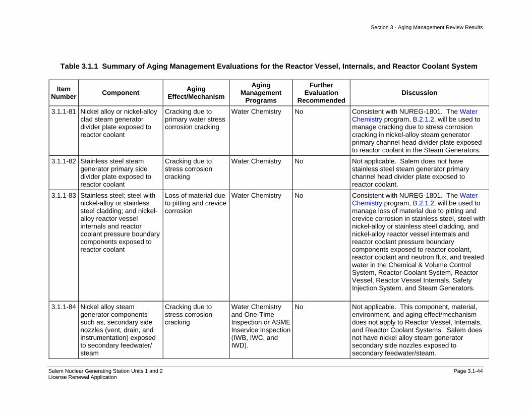
Section 3 - Aging Management Review Results
Salem Nuclear Generating Station Units 1 and 2 Page 3.1-44 License Renewal Application
Table 3.1.1 Summary of Aging Management Evaluations for the Reactor Vessel, Internals, and Reactor Coolant System
Item Number Component Aging
Effect/Mechanism Aging
Management Programs
Further Evaluation
Recommended Discussion
3.1.1-81 Nickel alloy or nickel-alloy clad steam generator divider plate exposed to reactor coolant
Cracking due to primary water stress corrosion cracking
Water Chemistry No Consistent with NUREG-1801. The Water Chemistry program, B.2.1.2, will be used to manage cracking due to stress corrosion cracking in nickel-alloy steam generator primary channel head divider plate exposed to reactor coolant in the Steam Generators.
3.1.1-82 Stainless steel steam generator primary side divider plate exposed to reactor coolant
Cracking due to stress corrosion cracking
Water Chemistry No Not applicable. Salem does not have stainless steel steam generator primary channel head divider plate exposed to reactor coolant.
3.1.1-83 Stainless steel; steel with nickel-alloy or stainless steel cladding; and nickel-alloy reactor vessel internals and reactor coolant pressure boundary components exposed to reactor coolant
Loss of material due to pitting and crevice corrosion
Water Chemistry No Consistent with NUREG-1801. The Water Chemistry program, B.2.1.2, will be used to manage loss of material due to pitting and crevice corrosion in stainless steel, steel with nickel-alloy or stainless steel cladding, and nickel-alloy reactor vessel internals and reactor coolant pressure boundary components exposed to reactor coolant, reactor coolant and neutron flux, and treated water in the Chemical & Volume Control System, Reactor Coolant System, Reactor Vessel, Reactor Vessel Internals, Safety Injection System, and Steam Generators.
3.1.1-84 Nickel alloy steam generator components such as, secondary side nozzles (vent, drain, and instrumentation) exposed to secondary feedwater/ steam
Cracking due to stress corrosion cracking
Water Chemistry and One-Time Inspection or ASME Inservice Inspection (IWB, IWC, and IWD).
No Not applicable. This component, material, environment, and aging effect/mechanism does not apply to Reactor Vessel, Internals, and Reactor Coolant Systems. Salem does not have nickel alloy steam generator secondary side nozzles exposed to secondary feedwater/steam.
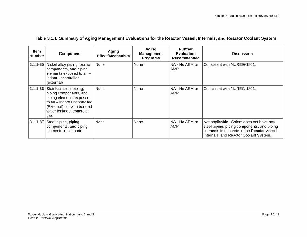
Section 3 - Aging Management Review Results
Salem Nuclear Generating Station Units 1 and 2 Page 3.1-45 License Renewal Application
Table 3.1.1 Summary of Aging Management Evaluations for the Reactor Vessel, Internals, and Reactor Coolant System
Item Number Component Aging
Effect/Mechanism Aging
Management Programs
Further Evaluation
Recommended Discussion
3.1.1-85 Nickel alloy piping, piping components, and piping elements exposed to air – indoor uncontrolled (external)
None None NA - No AEM or AMP
Consistent with NUREG-1801.
3.1.1-86 Stainless steel piping, piping components, and piping elements exposed to air – indoor uncontrolled (External); air with borated water leakage; concrete; gas
None None NA - No AEM or AMP
Consistent with NUREG-1801.
3.1.1-87 Steel piping, piping components, and piping elements in concrete
None None NA - No AEM or AMP
Not applicable. Salem does not have any steel piping, piping components, and piping elements in concrete in the Reactor Vessel, Internals, and Reactor Coolant System.

Section 3 - Aging Management Review Results
Salem Nuclear Generating Station, Unit No. 1 and Unit No. 2 Page 3.1-46 License Renewal Application
Table 3.1.2-1 Reactor Coolant System
Summary of Aging Management Evaluation
Table 3.1.2-1 Reactor Coolant System
Component Type
Intended Function
Material Environment Aging Effect Requiring
Management
Aging Management Programs
NUREG-1801 Vol. 2 Item
Table 1 Item Notes
Bolting Mechanical Closure Carbon and Low Alloy Steel
Bolting
Air - Indoor (External) Loss of Material/General, Pitting and Crevice
Corrosion
Bolting Integrity V.E-4 3.2.1-23 B
Bolting Mechanical Closure Carbon and Low Alloy Steel
Bolting
Air - Indoor (External) Loss of Preload/Thermal Effects, Gasket Creep,
and Self-Loosening
Bolting Integrity IV.C2-8 3.1.1-52 B
Bolting Mechanical Closure Carbon and Low Alloy Steel
Bolting
Air with Borated Water Leakage (External)
Loss of Material/Boric Acid Corrosion
Boric Acid Corrosion IV.C2-9 3.1.1-58 A
Bolting (Class 1) Mechanical Closure Carbon and Low Alloy Steel
Bolting
Air - Indoor (External) Cumulative Fatigue Damage/Fatigue
TLAA IV.C2-10 3.1.1-7 A, 1
Bolting (Class 1) Mechanical Closure Carbon and Low Alloy Steel
Bolting
Air - Indoor (External) Loss of Material/General, Pitting and Crevice
Corrosion
Bolting Integrity V.E-4 3.2.1-23 B
Bolting (Class 1) Mechanical Closure Carbon and Low Alloy Steel
Bolting
Air - Indoor (External) Loss of Preload/Thermal Effects, Gasket Creep,
and Self-Loosening
Bolting Integrity IV.C2-8 3.1.1-52 B
Bolting (Class 1) Mechanical Closure Carbon and Low Alloy Steel
Bolting
Air with Borated Water Leakage (External)
Loss of Material/Boric Acid Corrosion
Boric Acid Corrosion IV.C2-9 3.1.1-58 A
Bolting (Class 1) Mechanical Closure Stainless Steel Bolting
Air - Indoor (External) Cumulative Fatigue Damage/Fatigue
TLAA IV.C2-10 3.1.1-7 A, 1
Bolting (Class 1) Mechanical Closure Stainless Steel Bolting
Air - Indoor (External) Loss of Material/Pitting and Crevice Corrosion
Bolting Integrity H, 2
Bolting (Class 1) Mechanical Closure Stainless Steel Bolting
Air - Indoor (External) Loss of Preload/Thermal Effects, Gasket Creep,
and Self-Loosening
Bolting Integrity IV.C2-8 3.1.1-52 B

Section 3 - Aging Management Review Results
Salem Nuclear Generating Station, Unit No. 1 and Unit No. 2 Page 3.1-47 License Renewal Application
Table 3.1.2-1 Reactor Coolant System (Continued)
Component Type
Intended Function
Material Environment Aging Effect Requiring
Management
Aging Management Programs
NUREG-1801 Vol. 2 Item
Table 1 Item Notes
Bolting (Class 1) Mechanical Closure Stainless Steel Bolting
Air with Borated Water Leakage (External)
None None IV.E-3 3.1.1-86 C
Class 1 Piping, Fittings and Branch
Connections < NPS 4"
Direct Flow (thermal sleeve)
Stainless Steel Reactor Coolant (Internal)
Cracking/Stress Corrosion Cracking
ASME Section XI Inservice Inspection,
Subsections IWB, IWC, and IWD
IV.C2-2 3.1.1-68 A
Class 1 Piping, Fittings and Branch
Connections < NPS 4"
Direct Flow (thermal sleeve)
Stainless Steel Reactor Coolant (Internal)
Cracking/Stress Corrosion Cracking
Water Chemistry IV.C2-2 3.1.1-68 A
Class 1 Piping, Fittings and Branch
Connections < NPS 4"
Direct Flow (thermal sleeve)
Stainless Steel Reactor Coolant (Internal)
Cumulative Fatigue Damage/Fatigue
TLAA IV.C2-10 3.1.1-7 A, 1
Class 1 Piping, Fittings and Branch
Connections < NPS 4"
Direct Flow (thermal sleeve)
Stainless Steel Reactor Coolant (Internal)
Loss of Material/Pitting and Crevice Corrosion
Water Chemistry IV.C2-15 3.1.1-83 A
Class 1 Piping, Fittings and Branch
Connections < NPS 4"
Pressure Boundary Stainless Steel Air - Indoor (External) None None IV.E-2 3.1.1-86 A
Class 1 Piping, Fittings and Branch
Connections < NPS 4"
Pressure Boundary Stainless Steel Air with Borated Water Leakage (External)
None None IV.E-3 3.1.1-86 A
Class 1 Piping, Fittings and Branch
Connections < NPS 4"
Pressure Boundary Stainless Steel Reactor Coolant (Internal)
Cracking/Stress Corrosion Cracking, Thermal and
Mechanical Loading
ASME Section XI Inservice Inspection,
Subsections IWB, IWC, and IWD
IV.C2-1 3.1.1-70 A
Class 1 Piping, Fittings and Branch
Connections < NPS 4"
Pressure Boundary Stainless Steel Reactor Coolant (Internal)
Cracking/Stress Corrosion Cracking, Thermal and
Mechanical Loading
One-Time Inspection of ASME Code Class 1 Small
Bore-Piping
IV.C2-1 3.1.1-70 B

Section 3 - Aging Management Review Results
Salem Nuclear Generating Station, Unit No. 1 and Unit No. 2 Page 3.1-48 License Renewal Application
Table 3.1.2-1 Reactor Coolant System (Continued)
Component Type
Intended Function
Material Environment Aging Effect Requiring
Management
Aging Management Programs
NUREG-1801 Vol. 2 Item
Table 1 Item Notes
Class 1 Piping, Fittings and Branch
Connections < NPS 4"
Pressure Boundary Stainless Steel Reactor Coolant (Internal)
Cracking/Stress Corrosion Cracking, Thermal and
Mechanical Loading
Water Chemistry IV.C2-1 3.1.1-70 A
Class 1 Piping, Fittings and Branch
Connections < NPS 4"
Pressure Boundary Stainless Steel Reactor Coolant (Internal)
Cumulative Fatigue Damage/Fatigue
TLAA IV.C2-10 3.1.1-7 A, 1
Class 1 Piping, Fittings and Branch
Connections < NPS 4"
Pressure Boundary Stainless Steel Reactor Coolant (Internal)
Loss of Material/Pitting and Crevice Corrosion
Water Chemistry IV.C2-15 3.1.1-83 A
Heat exchanger components
(Reactor Coolant Pump Bearing Oil
and Thermal Barrier)
Evaluated with the Component Cooling
System
Not Applicable Not Applicable Not Applicable Not Applicable 8
Hoses (Reactor Coolant Pump Oil Lift component)
Leakage Boundary Stainless Steel Air - Indoor (External) None None IV.E-2 3.1.1-86 A
Hoses (Reactor Coolant Pump Oil Lift component)
Leakage Boundary Stainless Steel Air with Borated Water Leakage (External)
None None IV.E-3 3.1.1-86 A
Hoses (Reactor Coolant Pump Oil Lift component)
Leakage Boundary Stainless Steel Lubricating Oil (Internal) Loss of Material/Pitting and Crevice Corrosion
Lubricating Oil Analysis VII.C2-12 3.3.1-33 B
Hoses (Reactor Coolant Pump Oil Lift component)
Leakage Boundary Stainless Steel Lubricating Oil (Internal) Loss of Material/Pitting and Crevice Corrosion
One-Time Inspection VII.C2-12 3.3.1-33 A
Piping and Fittings Leakage Boundary Carbon Steel Air - Indoor (External) Loss of Material/General Corrosion
External Surfaces Monitoring
V.E-7 3.2.1-31 A
Piping and Fittings Leakage Boundary Carbon Steel Air with Borated Water Leakage (External)
Loss of Material/Boric Acid Corrosion
Boric Acid Corrosion IV.C2-9 3.1.1-58 A

Section 3 - Aging Management Review Results
Salem Nuclear Generating Station, Unit No. 1 and Unit No. 2 Page 3.1-49 License Renewal Application
Table 3.1.2-1 Reactor Coolant System (Continued)
Component Type
Intended Function
Material Environment Aging Effect Requiring
Management
Aging Management Programs
NUREG-1801 Vol. 2 Item
Table 1 Item Notes
Piping and Fittings Leakage Boundary Carbon Steel Lubricating Oil (Internal) Loss of Material/General, Pitting, Crevice, and
Microbiologically Influenced Corrosion
Lubricating Oil Analysis VIII.G-6 3.4.1-12 D
Piping and Fittings Leakage Boundary Carbon Steel Lubricating Oil (Internal) Loss of Material/General, Pitting, Crevice, and
Microbiologically Influenced Corrosion
One-Time Inspection VIII.G-6 3.4.1-12 C
Piping and Fittings Pressure Boundary Carbon Steel Air - Indoor (External) Loss of Material/General Corrosion
External Surfaces Monitoring
V.E-7 3.2.1-31 A
Piping and Fittings Pressure Boundary Carbon Steel Air with Borated Water Leakage (External)
Loss of Material/Boric Acid Corrosion
Boric Acid Corrosion IV.C2-9 3.1.1-58 A
Piping and Fittings Pressure Boundary Carbon Steel Air with Steam or Water Leakage (External)
Loss of Material/General, Pitting and Crevice
Corrosion
External Surfaces Monitoring
VII.F3-10 3.3.1-59 C
Piping and Fittings Pressure Boundary Carbon Steel Air/Gas - Dry (Internal) None None VII.J-23 3.3.1-97 A Piping and Fittings Pressure Boundary Stainless Steel Air - Indoor (External) None None IV.E-2 3.1.1-86 A Piping and Fittings Pressure Boundary Stainless Steel Air with Borated Water
Leakage (External) None None IV.E-3 3.1.1-86 A
Piping and Fittings Pressure Boundary Stainless Steel Air with Steam or Water Leakage (External)
Loss of Material/Pitting and Crevice Corrosion
Periodic Inspection VII.F3-1 3.3.1-27 E, 3
Piping and Fittings Pressure Boundary Stainless Steel Reactor Coolant (Internal)
Cracking/Stress Corrosion Cracking
ASME Section XI Inservice Inspection,
Subsections IWB, IWC, and IWD
IV.C2-27 3.1.1-68 A
Piping and Fittings Pressure Boundary Stainless Steel Reactor Coolant (Internal)
Cracking/Stress Corrosion Cracking
Water Chemistry IV.C2-27 3.1.1-68 A
Piping and Fittings Pressure Boundary Stainless Steel Reactor Coolant (Internal)
Cumulative Fatigue Damage/Fatigue
TLAA IV.C2-10 3.1.1-7 A, 1
Piping and Fittings Pressure Boundary Stainless Steel Reactor Coolant (Internal)
Loss of Material/Pitting and Crevice Corrosion
Water Chemistry IV.C2-15 3.1.1-83 A
Piping and Fittings (Class 1)
Pressure Boundary Stainless Steel Air - Indoor (External) None None IV.E-2 3.1.1-86 A

Section 3 - Aging Management Review Results
Salem Nuclear Generating Station, Unit No. 1 and Unit No. 2 Page 3.1-50 License Renewal Application
Table 3.1.2-1 Reactor Coolant System (Continued)
Component Type
Intended Function
Material Environment Aging Effect Requiring
Management
Aging Management Programs
NUREG-1801 Vol. 2 Item
Table 1 Item Notes
Piping and Fittings (Class 1)
Pressure Boundary Stainless Steel Air with Borated Water Leakage (External)
None None IV.E-3 3.1.1-86 A
Piping and Fittings (Class 1)
Pressure Boundary Stainless Steel Reactor Coolant (Internal)
Cracking/Stress Corrosion Cracking
ASME Section XI Inservice Inspection,
Subsections IWB, IWC, and IWD
IV.C2-27 3.1.1-68 A
Piping and Fittings (Class 1)
Pressure Boundary Stainless Steel Reactor Coolant (Internal)
Cracking/Stress Corrosion Cracking
Water Chemistry IV.C2-27 3.1.1-68 A
Piping and Fittings (Class 1)
Pressure Boundary Stainless Steel Reactor Coolant (Internal)
Cumulative Fatigue Damage/Fatigue
TLAA IV.C2-10 3.1.1-7 A, 1
Piping and Fittings (Class 1)
Pressure Boundary Stainless Steel Reactor Coolant (Internal)
Loss of Material/Pitting and Crevice Corrosion
Water Chemistry IV.C2-15 3.1.1-83 A
Pressurizer Pressure Boundary Carbon or Low Alloy Steel with Stainless Steel
Cladding
Air - Indoor (External) Loss of Material/General Corrosion
External Surfaces Monitoring
V.E-7 3.2.1-31 A
Pressurizer Pressure Boundary Carbon or Low Alloy Steel with Stainless Steel
Cladding
Air with Borated Water Leakage (External)
Loss of Material/Boric Acid Corrosion
Boric Acid Corrosion IV.C2-9 3.1.1-58 A
Pressurizer Pressure Boundary Carbon or Low Alloy Steel with Stainless Steel
Cladding
Reactor Coolant (Internal)
Cracking/Cyclic Loading ASME Section XI Inservice Inspection,
Subsections IWB, IWC, and IWD
IV.C2-18 3.1.1-67 A
Pressurizer Pressure Boundary Carbon or Low Alloy Steel with Stainless Steel
Cladding
Reactor Coolant (Internal)
Cracking/Cyclic Loading Water Chemistry IV.C2-18 3.1.1-67 A
Pressurizer Pressure Boundary Carbon or Low Alloy Steel with Stainless Steel
Cladding
Reactor Coolant (Internal)
Cracking/Stress Corrosion Cracking
ASME Section XI Inservice Inspection,
Subsections IWB, IWC, and IWD
IV.C2-19 3.1.1-64 A

Section 3 - Aging Management Review Results
Salem Nuclear Generating Station, Unit No. 1 and Unit No. 2 Page 3.1-51 License Renewal Application
Table 3.1.2-1 Reactor Coolant System (Continued)
Component Type
Intended Function
Material Environment Aging Effect Requiring
Management
Aging Management Programs
NUREG-1801 Vol. 2 Item
Table 1 Item Notes
Pressurizer Pressure Boundary Carbon or Low Alloy Steel with Stainless Steel
Cladding
Reactor Coolant (Internal)
Cracking/Stress Corrosion Cracking
Water Chemistry IV.C2-19 3.1.1-64 A
Pressurizer Pressure Boundary Carbon or Low Alloy Steel with Stainless Steel
Cladding
Reactor Coolant (Internal)
Cumulative Fatigue Damage/Fatigue
TLAA IV.C2-25 3.1.1-8 A, 1
Pressurizer Pressure Boundary Carbon or Low Alloy Steel with Stainless Steel
Cladding
Reactor Coolant (Internal)
Loss of Material/Pitting and Crevice Corrosion
Water Chemistry IV.C2-15 3.1.1-83 A
Pressurizer (integral support -
skirt)
Structural Support Carbon Steel Air - Indoor (External) Cracking/Cyclic Loading ASME Section XI Inservice Inspection,
Subsections IWB, IWC, and IWD
IV.C2-16 3.1.1-61 A
Pressurizer (integral support -
skirt)
Structural Support Carbon Steel Air - Indoor (External) Loss of Material/General Corrosion
External Surfaces Monitoring
V.E-7 3.2.1-31 A
Pressurizer (integral support -
skirt)
Structural Support Carbon Steel Air with Borated Water Leakage (External)
Loss of Material/Boric Acid Corrosion
Boric Acid Corrosion IV.C2-9 3.1.1-58 A
Pressurizer (manway, insert,
diaphragm)
Pressure Boundary Carbon Steel Air - Indoor (External) Loss of Material/General Corrosion
External Surfaces Monitoring
V.E-7 3.2.1-31 A
Pressurizer (manway, insert,
diaphragm)
Pressure Boundary Carbon Steel Air with Borated Water Leakage (External)
Loss of Material/Boric Acid Corrosion
Boric Acid Corrosion IV.C2-9 3.1.1-58 A
Pressurizer (manway, insert,
diaphragm)
Pressure Boundary Stainless Steel Air - Indoor (External) None None IV.E-2 3.1.1-86 C
Pressurizer (manway, insert,
diaphragm)
Pressure Boundary Stainless Steel Air with Borated Water Leakage (External)
None None IV.E-3 3.1.1-86 C
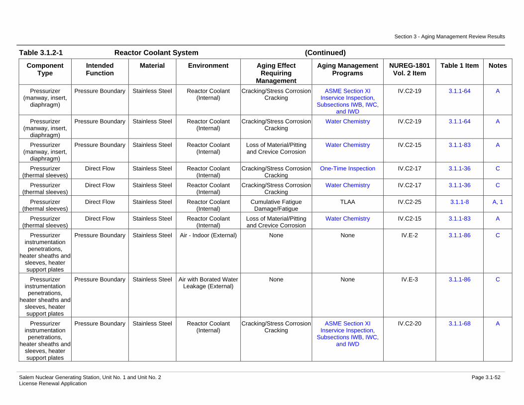
Section 3 - Aging Management Review Results
Salem Nuclear Generating Station, Unit No. 1 and Unit No. 2 Page 3.1-52 License Renewal Application
Table 3.1.2-1 Reactor Coolant System (Continued)
Component Type
Intended Function
Material Environment Aging Effect Requiring
Management
Aging Management Programs
NUREG-1801 Vol. 2 Item
Table 1 Item Notes
Pressurizer (manway, insert,
diaphragm)
Pressure Boundary Stainless Steel Reactor Coolant (Internal)
Cracking/Stress Corrosion Cracking
ASME Section XI Inservice Inspection,
Subsections IWB, IWC, and IWD
IV.C2-19 3.1.1-64 A
Pressurizer (manway, insert,
diaphragm)
Pressure Boundary Stainless Steel Reactor Coolant (Internal)
Cracking/Stress Corrosion Cracking
Water Chemistry IV.C2-19 3.1.1-64 A
Pressurizer (manway, insert,
diaphragm)
Pressure Boundary Stainless Steel Reactor Coolant (Internal)
Loss of Material/Pitting and Crevice Corrosion
Water Chemistry IV.C2-15 3.1.1-83 A
Pressurizer (thermal sleeves)
Direct Flow Stainless Steel Reactor Coolant (Internal)
Cracking/Stress Corrosion Cracking
One-Time Inspection IV.C2-17 3.1.1-36 C
Pressurizer (thermal sleeves)
Direct Flow Stainless Steel Reactor Coolant (Internal)
Cracking/Stress Corrosion Cracking
Water Chemistry IV.C2-17 3.1.1-36 C
Pressurizer (thermal sleeves)
Direct Flow Stainless Steel Reactor Coolant (Internal)
Cumulative Fatigue Damage/Fatigue
TLAA IV.C2-25 3.1.1-8 A, 1
Pressurizer (thermal sleeves)
Direct Flow Stainless Steel Reactor Coolant (Internal)
Loss of Material/Pitting and Crevice Corrosion
Water Chemistry IV.C2-15 3.1.1-83 A
Pressurizer instrumentation penetrations,
heater sheaths and sleeves, heater support plates
Pressure Boundary Stainless Steel Air - Indoor (External) None None IV.E-2 3.1.1-86 C
Pressurizer instrumentation penetrations,
heater sheaths and sleeves, heater support plates
Pressure Boundary Stainless Steel Air with Borated Water Leakage (External)
None None IV.E-3 3.1.1-86 C
Pressurizer instrumentation penetrations,
heater sheaths and sleeves, heater support plates
Pressure Boundary Stainless Steel Reactor Coolant (Internal)
Cracking/Stress Corrosion Cracking
ASME Section XI Inservice Inspection,
Subsections IWB, IWC, and IWD
IV.C2-20 3.1.1-68 A

Section 3 - Aging Management Review Results
Salem Nuclear Generating Station, Unit No. 1 and Unit No. 2 Page 3.1-53 License Renewal Application
Table 3.1.2-1 Reactor Coolant System (Continued)
Component Type
Intended Function
Material Environment Aging Effect Requiring
Management
Aging Management Programs
NUREG-1801 Vol. 2 Item
Table 1 Item Notes
Pressurizer instrumentation penetrations,
heater sheaths and sleeves, heater support plates
Pressure Boundary Stainless Steel Reactor Coolant (Internal)
Cracking/Stress Corrosion Cracking
Water Chemistry IV.C2-20 3.1.1-68 A
Pressurizer instrumentation penetrations,
heater sheaths and sleeves, heater support plates
Pressure Boundary Stainless Steel Reactor Coolant (Internal)
Cumulative Fatigue Damage/Fatigue
TLAA IV.C2-25 3.1.1-8 A, 1
Pressurizer instrumentation penetrations,
heater sheaths and sleeves, heater support plates
Pressure Boundary Stainless Steel Reactor Coolant (Internal)
Loss of Material/Pitting and Crevice Corrosion
Water Chemistry IV.C2-15 3.1.1-83 A
Pressurizer surge and steam space
nozzles, safe ends, and welds
Pressure Boundary Stainless Steel Air - Indoor (External) None None IV.E-2 3.1.1-86 C
Pressurizer surge and steam space
nozzles, safe ends, and welds
Pressure Boundary Stainless Steel Air with Borated Water Leakage (External)
None None IV.E-3 3.1.1-86 C
Pressurizer surge and steam space
nozzles, safe ends, and welds
Pressure Boundary Stainless Steel Reactor Coolant (Internal)
Cracking/Cyclic Loading ASME Section XI Inservice Inspection,
Subsections IWB, IWC, and IWD
IV.C2-18 3.1.1-67 A
Pressurizer surge and steam space
nozzles, safe ends, and welds
Pressure Boundary Stainless Steel Reactor Coolant (Internal)
Cracking/Cyclic Loading Water Chemistry IV.C2-18 3.1.1-67 A

Section 3 - Aging Management Review Results
Salem Nuclear Generating Station, Unit No. 1 and Unit No. 2 Page 3.1-54 License Renewal Application
Table 3.1.2-1 Reactor Coolant System (Continued)
Component Type
Intended Function
Material Environment Aging Effect Requiring
Management
Aging Management Programs
NUREG-1801 Vol. 2 Item
Table 1 Item Notes
Pressurizer surge and steam space
nozzles, safe ends, and welds
Pressure Boundary Stainless Steel Reactor Coolant (Internal)
Cracking/Stress Corrosion Cracking
ASME Section XI Inservice Inspection,
Subsections IWB, IWC, and IWD
IV.C2-19 3.1.1-64 A
Pressurizer surge and steam space
nozzles, safe ends, and welds
Pressure Boundary Stainless Steel Reactor Coolant (Internal)
Cracking/Stress Corrosion Cracking
Water Chemistry IV.C2-19 3.1.1-64 A
Pressurizer surge and steam space
nozzles, safe ends, and welds
Pressure Boundary Stainless Steel Reactor Coolant (Internal)
Cumulative Fatigue Damage/Fatigue
TLAA IV.C2-25 3.1.1-8 A, 1
Pressurizer surge and steam space
nozzles, safe ends, and welds
Pressure Boundary Stainless Steel Reactor Coolant (Internal)
Loss of Material/Pitting and Crevice Corrosion
Water Chemistry IV.C2-15 3.1.1-83 A
Pump Casing (Reactor Coolant
Pump Oil Lift Pump)
Leakage Boundary Carbon Steel Air - Indoor (External) Loss of Material/General Corrosion
External Surfaces Monitoring
V.E-7 3.2.1-31 A
Pump Casing (Reactor Coolant
Pump Oil Lift Pump)
Leakage Boundary Carbon Steel Air with Borated Water Leakage (External)
Loss of Material/Boric Acid Corrosion
Boric Acid Corrosion IV.C2-9 3.1.1-58 A
Pump Casing (Reactor Coolant
Pump Oil Lift Pump)
Leakage Boundary Carbon Steel Lubricating Oil (Internal) Loss of Material/General, Pitting, Crevice, and
Microbiologically Influenced Corrosion
Lubricating Oil Analysis VIII.G-6 3.4.1-12 D
Pump Casing (Reactor Coolant
Pump Oil Lift Pump)
Leakage Boundary Carbon Steel Lubricating Oil (Internal) Loss of Material/General, Pitting, Crevice, and
Microbiologically Influenced Corrosion
One-Time Inspection VIII.G-6 3.4.1-12 C
Pump Casing (Reactor Coolant
Pump)
Pressure Boundary Cast Austenitic Stainless Steel
(CASS)
Air - Indoor (External) None None IV.E-2 3.1.1-86 A

Section 3 - Aging Management Review Results
Salem Nuclear Generating Station, Unit No. 1 and Unit No. 2 Page 3.1-55 License Renewal Application
Table 3.1.2-1 Reactor Coolant System (Continued)
Component Type
Intended Function
Material Environment Aging Effect Requiring
Management
Aging Management Programs
NUREG-1801 Vol. 2 Item
Table 1 Item Notes
Pump Casing (Reactor Coolant
Pump)
Pressure Boundary Cast Austenitic Stainless Steel
(CASS)
Air with Borated Water Leakage (External)
None None IV.E-3 3.1.1-86 A
Pump Casing (Reactor Coolant
Pump)
Pressure Boundary Cast Austenitic Stainless Steel
(CASS)
Reactor Coolant (Internal)
Cracking/Stress Corrosion Cracking
ASME Section XI Inservice Inspection,
Subsections IWB, IWC, and IWD
IV.C2-5 3.1.1-68 A
Pump Casing (Reactor Coolant
Pump)
Pressure Boundary Cast Austenitic Stainless Steel
(CASS)
Reactor Coolant (Internal)
Cracking/Stress Corrosion Cracking
Water Chemistry IV.C2-5 3.1.1-68 A
Pump Casing (Reactor Coolant
Pump)
Pressure Boundary Cast Austenitic Stainless Steel
(CASS)
Reactor Coolant (Internal)
Cumulative Fatigue Damage/Fatigue
TLAA IV.C2-25 3.1.1-8 A, 1
Pump Casing (Reactor Coolant
Pump)
Pressure Boundary Cast Austenitic Stainless Steel
(CASS)
Reactor Coolant (Internal)
Loss of Fracture Toughness/Thermal Aging
Embrittlement
ASME Section XI Inservice Inspection,
Subsections IWB, IWC, and IWD
IV.C2-6 3.1.1-55 A
Pump Casing (Reactor Coolant
Pump)
Pressure Boundary Cast Austenitic Stainless Steel
(CASS)
Reactor Coolant (Internal)
Loss of Fracture Toughness/Thermal Aging
Embrittlement
TLAA IV.C2-6 3.1.1-55 E, 1, 4
Pump Casing (Reactor Coolant
Pump)
Pressure Boundary Cast Austenitic Stainless Steel
(CASS)
Reactor Coolant (Internal)
Loss of Material/Pitting and Crevice Corrosion
Water Chemistry IV.C2-15 3.1.1-83 A
Pump Casing (Reactor Coolant
Pump)
Pressure Boundary Stainless Steel Air - Indoor (External) None None IV.E-2 3.1.1-86 A
Pump Casing (Reactor Coolant
Pump)
Pressure Boundary Stainless Steel Air with Borated Water Leakage (External)
None None IV.E-3 3.1.1-86 A
Pump Casing (Reactor Coolant
Pump)
Pressure Boundary Stainless Steel Reactor Coolant (Internal)
Cracking/Stress Corrosion Cracking
ASME Section XI Inservice Inspection,
Subsections IWB, IWC, and IWD
IV.C2-2 3.1.1-68 C

Section 3 - Aging Management Review Results
Salem Nuclear Generating Station, Unit No. 1 and Unit No. 2 Page 3.1-56 License Renewal Application
Table 3.1.2-1 Reactor Coolant System (Continued)
Component Type
Intended Function
Material Environment Aging Effect Requiring
Management
Aging Management Programs
NUREG-1801 Vol. 2 Item
Table 1 Item Notes
Pump Casing (Reactor Coolant
Pump)
Pressure Boundary Stainless Steel Reactor Coolant (Internal)
Cracking/Stress Corrosion Cracking
Water Chemistry IV.C2-2 3.1.1-68 C
Pump Casing (Reactor Coolant
Pump)
Pressure Boundary Stainless Steel Reactor Coolant (Internal)
Cumulative Fatigue Damage/Fatigue
TLAA IV.C2-25 3.1.1-8 A, 1
Pump Casing (Reactor Coolant
Pump)
Pressure Boundary Stainless Steel Reactor Coolant (Internal)
Loss of Material/Pitting and Crevice Corrosion
Water Chemistry IV.C2-15 3.1.1-83 A
Reactor Coolant Pressure Boundary Components (hot leg and cold leg
piping)
Pressure Boundary Cast Austenitic Stainless Steel
(CASS)
Air - Indoor (External) None None IV.E-2 3.1.1-86 A
Reactor Coolant Pressure Boundary Components (hot leg and cold leg
piping)
Pressure Boundary Cast Austenitic Stainless Steel
(CASS)
Air with Borated Water Leakage (External)
None None IV.E-3 3.1.1-86 A
Reactor Coolant Pressure Boundary Components (hot leg and cold leg
piping)
Pressure Boundary Cast Austenitic Stainless Steel
(CASS)
Reactor Coolant (Internal)
Cracking/Stress Corrosion Cracking
Thermal Aging Embrittlement of Cast
Austenitic Stainless Steel (CASS)
IV.C2-3 3.1.1-24 A
Reactor Coolant Pressure Boundary Components (hot leg and cold leg
piping)
Pressure Boundary Cast Austenitic Stainless Steel
(CASS)
Reactor Coolant (Internal)
Cracking/Stress Corrosion Cracking
Water Chemistry IV.C2-3 3.1.1-24 A
Reactor Coolant Pressure Boundary Components (hot leg and cold leg
piping)
Pressure Boundary Cast Austenitic Stainless Steel
(CASS)
Reactor Coolant (Internal)
Cumulative Fatigue Damage/Fatigue
TLAA IV.C2-25 3.1.1-8 A, 1

Section 3 - Aging Management Review Results
Salem Nuclear Generating Station, Unit No. 1 and Unit No. 2 Page 3.1-57 License Renewal Application
Table 3.1.2-1 Reactor Coolant System (Continued)
Component Type
Intended Function
Material Environment Aging Effect Requiring
Management
Aging Management Programs
NUREG-1801 Vol. 2 Item
Table 1 Item Notes
Reactor Coolant Pressure Boundary Components (hot leg and cold leg
piping)
Pressure Boundary Cast Austenitic Stainless Steel
(CASS)
Reactor Coolant (Internal)
Loss of Fracture Toughness/Thermal Aging
Embrittlement
Thermal Aging Embrittlement of Cast
Austenitic Stainless Steel (CASS)
IV.C2-4 3.1.1-57 A
Reactor Coolant Pressure Boundary Components (hot leg and cold leg
piping)
Pressure Boundary Cast Austenitic Stainless Steel
(CASS)
Reactor Coolant (Internal)
Loss of Material/Pitting and Crevice Corrosion
Water Chemistry IV.C2-15 3.1.1-83 A
Reactor Coolant Pressure Boundary Components (hot leg and cold leg
piping)
Pressure Boundary Stainless Steel Air - Indoor (External) None None IV.E-2 3.1.1-86 A
Reactor Coolant Pressure Boundary Components (hot leg and cold leg
piping)
Pressure Boundary Stainless Steel Air with Borated Water Leakage (External)
None None IV.E-3 3.1.1-86 A
Reactor Coolant Pressure Boundary Components (hot leg and cold leg
piping)
Pressure Boundary Stainless Steel Reactor Coolant (Internal)
Cracking/Cyclic Loading ASME Section XI Inservice Inspection,
Subsections IWB, IWC, and IWD
IV.C2-26 3.1.1-62 A
Reactor Coolant Pressure Boundary Components (hot leg and cold leg
piping)
Pressure Boundary Stainless Steel Reactor Coolant (Internal)
Cracking/Stress Corrosion Cracking
ASME Section XI Inservice Inspection,
Subsections IWB, IWC, and IWD
IV.C2-27 3.1.1-68 A
Reactor Coolant Pressure Boundary Components (hot leg and cold leg
piping)
Pressure Boundary Stainless Steel Reactor Coolant (Internal)
Cracking/Stress Corrosion Cracking
Water Chemistry IV.C2-27 3.1.1-68 A
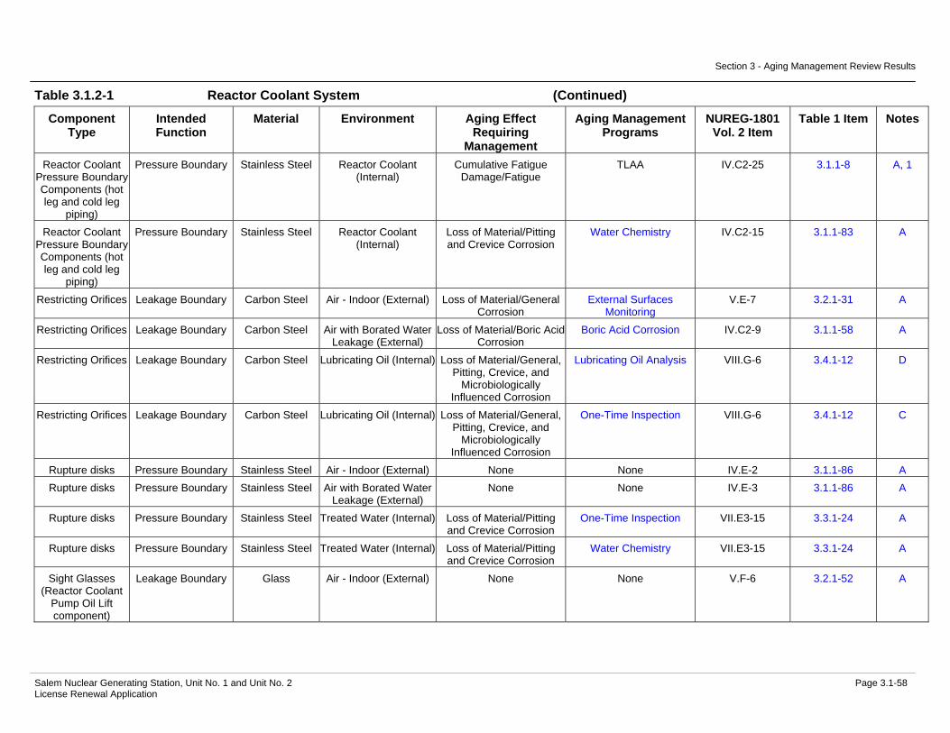
Section 3 - Aging Management Review Results
Salem Nuclear Generating Station, Unit No. 1 and Unit No. 2 Page 3.1-58 License Renewal Application
Table 3.1.2-1 Reactor Coolant System (Continued)
Component Type
Intended Function
Material Environment Aging Effect Requiring
Management
Aging Management Programs
NUREG-1801 Vol. 2 Item
Table 1 Item Notes
Reactor Coolant Pressure Boundary Components (hot leg and cold leg
piping)
Pressure Boundary Stainless Steel Reactor Coolant (Internal)
Cumulative Fatigue Damage/Fatigue
TLAA IV.C2-25 3.1.1-8 A, 1
Reactor Coolant Pressure Boundary Components (hot leg and cold leg
piping)
Pressure Boundary Stainless Steel Reactor Coolant (Internal)
Loss of Material/Pitting and Crevice Corrosion
Water Chemistry IV.C2-15 3.1.1-83 A
Restricting Orifices Leakage Boundary Carbon Steel Air - Indoor (External) Loss of Material/General Corrosion
External Surfaces Monitoring
V.E-7 3.2.1-31 A
Restricting Orifices Leakage Boundary Carbon Steel Air with Borated Water Leakage (External)
Loss of Material/Boric Acid Corrosion
Boric Acid Corrosion IV.C2-9 3.1.1-58 A
Restricting Orifices Leakage Boundary Carbon Steel Lubricating Oil (Internal) Loss of Material/General, Pitting, Crevice, and
Microbiologically Influenced Corrosion
Lubricating Oil Analysis VIII.G-6 3.4.1-12 D
Restricting Orifices Leakage Boundary Carbon Steel Lubricating Oil (Internal) Loss of Material/General, Pitting, Crevice, and
Microbiologically Influenced Corrosion
One-Time Inspection VIII.G-6 3.4.1-12 C
Rupture disks Pressure Boundary Stainless Steel Air - Indoor (External) None None IV.E-2 3.1.1-86 A Rupture disks Pressure Boundary Stainless Steel Air with Borated Water
Leakage (External) None None IV.E-3 3.1.1-86 A
Rupture disks Pressure Boundary Stainless Steel Treated Water (Internal) Loss of Material/Pitting and Crevice Corrosion
One-Time Inspection VII.E3-15 3.3.1-24 A
Rupture disks Pressure Boundary Stainless Steel Treated Water (Internal) Loss of Material/Pitting and Crevice Corrosion
Water Chemistry VII.E3-15 3.3.1-24 A
Sight Glasses (Reactor Coolant
Pump Oil Lift component)
Leakage Boundary Glass Air - Indoor (External) None None V.F-6 3.2.1-52 A
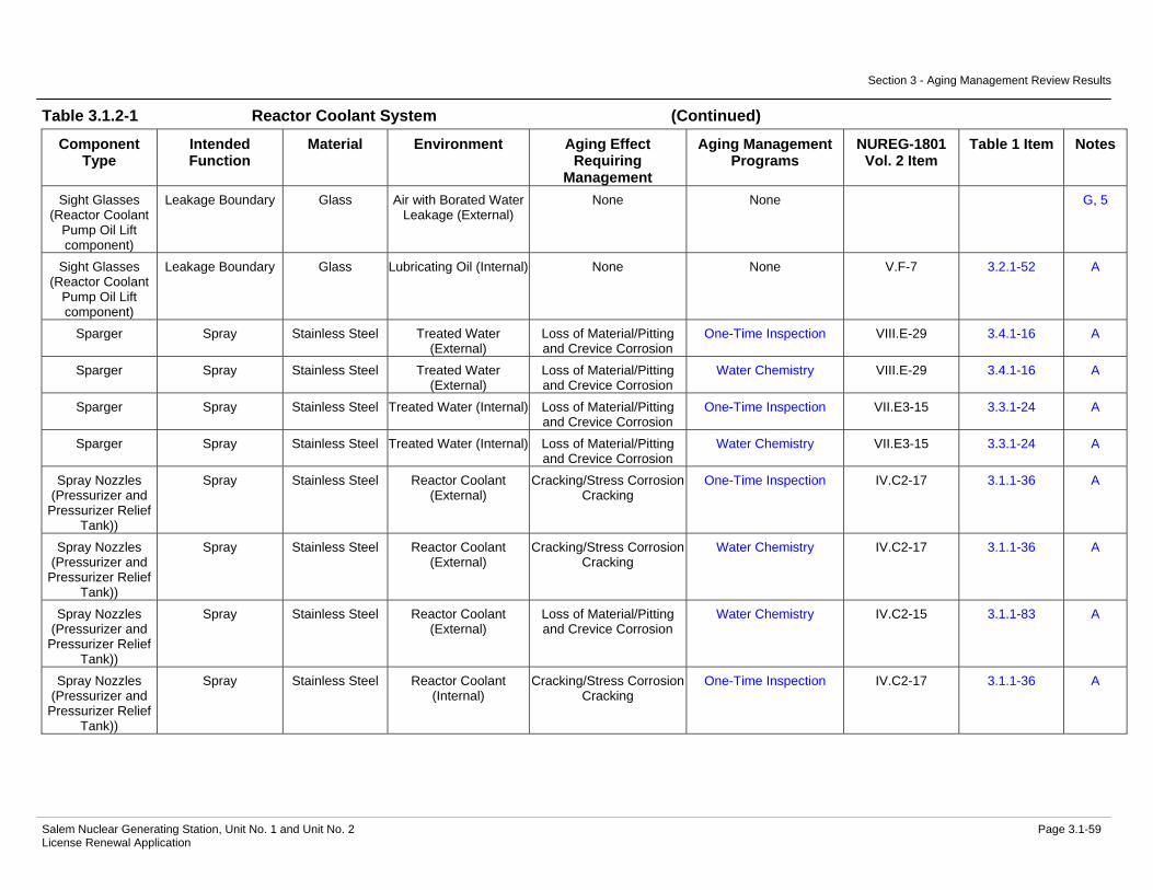
Section 3 - Aging Management Review Results
Salem Nuclear Generating Station, Unit No. 1 and Unit No. 2 Page 3.1-59 License Renewal Application
Table 3.1.2-1 Reactor Coolant System (Continued)
Component Type
Intended Function
Material Environment Aging Effect Requiring
Management
Aging Management Programs
NUREG-1801 Vol. 2 Item
Table 1 Item Notes
Sight Glasses (Reactor Coolant
Pump Oil Lift component)
Leakage Boundary Glass Air with Borated Water Leakage (External)
None None G, 5
Sight Glasses (Reactor Coolant
Pump Oil Lift component)
Leakage Boundary Glass Lubricating Oil (Internal) None None V.F-7 3.2.1-52 A
Sparger Spray Stainless Steel Treated Water (External)
Loss of Material/Pitting and Crevice Corrosion
One-Time Inspection VIII.E-29 3.4.1-16 A
Sparger Spray Stainless Steel Treated Water (External)
Loss of Material/Pitting and Crevice Corrosion
Water Chemistry VIII.E-29 3.4.1-16 A
Sparger Spray Stainless Steel Treated Water (Internal) Loss of Material/Pitting and Crevice Corrosion
One-Time Inspection VII.E3-15 3.3.1-24 A
Sparger Spray Stainless Steel Treated Water (Internal) Loss of Material/Pitting and Crevice Corrosion
Water Chemistry VII.E3-15 3.3.1-24 A
Spray Nozzles (Pressurizer and
Pressurizer Relief Tank))
Spray Stainless Steel Reactor Coolant (External)
Cracking/Stress Corrosion Cracking
One-Time Inspection IV.C2-17 3.1.1-36 A
Spray Nozzles (Pressurizer and
Pressurizer Relief Tank))
Spray Stainless Steel Reactor Coolant (External)
Cracking/Stress Corrosion Cracking
Water Chemistry IV.C2-17 3.1.1-36 A
Spray Nozzles (Pressurizer and
Pressurizer Relief Tank))
Spray Stainless Steel Reactor Coolant (External)
Loss of Material/Pitting and Crevice Corrosion
Water Chemistry IV.C2-15 3.1.1-83 A
Spray Nozzles (Pressurizer and
Pressurizer Relief Tank))
Spray Stainless Steel Reactor Coolant (Internal)
Cracking/Stress Corrosion Cracking
One-Time Inspection IV.C2-17 3.1.1-36 A

Section 3 - Aging Management Review Results
Salem Nuclear Generating Station, Unit No. 1 and Unit No. 2 Page 3.1-60 License Renewal Application
Table 3.1.2-1 Reactor Coolant System (Continued)
Component Type
Intended Function
Material Environment Aging Effect Requiring
Management
Aging Management Programs
NUREG-1801 Vol. 2 Item
Table 1 Item Notes
Spray Nozzles (Pressurizer and
Pressurizer Relief Tank))
Spray Stainless Steel Reactor Coolant (Internal)
Cracking/Stress Corrosion Cracking
Water Chemistry IV.C2-17 3.1.1-36 A
Spray Nozzles (Pressurizer and
Pressurizer Relief Tank))
Spray Stainless Steel Reactor Coolant (Internal)
Loss of Material/Pitting and Crevice Corrosion
Water Chemistry IV.C2-15 3.1.1-83 A
Strainer Body (Reactor Coolant
Pump Oil Lift component)
Leakage Boundary Carbon Steel Air - Indoor (External) Loss of Material/General Corrosion
External Surfaces Monitoring
V.E-7 3.2.1-31 A
Strainer Body (Reactor Coolant
Pump Oil Lift component)
Leakage Boundary Carbon Steel Air with Borated Water Leakage (External)
Loss of Material/Boric Acid Corrosion
Boric Acid Corrosion IV.C2-9 3.1.1-58 A
Strainer Body (Reactor Coolant
Pump Oil Lift component)
Leakage Boundary Carbon Steel Lubricating Oil (Internal) Loss of Material/General, Pitting, Crevice, and
Microbiologically Influenced Corrosion
Lubricating Oil Analysis VIII.G-6 3.4.1-12 D
Strainer Body (Reactor Coolant
Pump Oil Lift component)
Leakage Boundary Carbon Steel Lubricating Oil (Internal) Loss of Material/General, Pitting, Crevice, and
Microbiologically Influenced Corrosion
One-Time Inspection VIII.G-6 3.4.1-12 C
Tanks (Pressurizer Relief Tank)
Pressure Boundary Carbon Steel Air - Indoor (External) Loss of Material/General Corrosion
External Surfaces Monitoring
V.E-7 3.2.1-31 A
Tanks (Pressurizer Relief Tank)
Pressure Boundary Carbon Steel Air with Borated Water Leakage (External)
Loss of Material/Boric Acid Corrosion
Boric Acid Corrosion IV.C2-9 3.1.1-58 A
Tanks (Pressurizer Relief Tank)
Pressure Boundary Carbon Steel Treated Water (Internal) Loss of Material/General, Pitting and Crevice
Corrosion
One-Time Inspection VIII.E-40 3.4.1-6 A
Tanks (Pressurizer Relief Tank)
Pressure Boundary Carbon Steel Treated Water (Internal) Loss of Material/General, Pitting and Crevice
Corrosion
Water Chemistry VIII.E-40 3.4.1-6 A

Section 3 - Aging Management Review Results
Salem Nuclear Generating Station, Unit No. 1 and Unit No. 2 Page 3.1-61 License Renewal Application
Table 3.1.2-1 Reactor Coolant System (Continued)
Component Type
Intended Function
Material Environment Aging Effect Requiring
Management
Aging Management Programs
NUREG-1801 Vol. 2 Item
Table 1 Item Notes
Tanks (Reactor Coolant Pump
Upper and Lower Oil Reservoirs)
Leakage Boundary Carbon Steel Air - Indoor (External) Loss of Material/General Corrosion
External Surfaces Monitoring
V.E-7 3.2.1-31 A
Tanks (Reactor Coolant Pump
Upper and Lower Oil Reservoirs)
Leakage Boundary Carbon Steel Air with Borated Water Leakage (External)
Loss of Material/Boric Acid Corrosion
Boric Acid Corrosion IV.C2-9 3.1.1-58 A
Tanks (Reactor Coolant Pump
Upper and Lower Oil Reservoirs)
Leakage Boundary Carbon Steel Lubricating Oil (Internal) Loss of Material/General, Pitting, Crevice, and
Microbiologically Influenced Corrosion
Lubricating Oil Analysis VIII.G-6 3.4.1-12 D
Tanks (Reactor Coolant Pump
Upper and Lower Oil Reservoirs)
Leakage Boundary Carbon Steel Lubricating Oil (Internal) Loss of Material/General, Pitting, Crevice, and
Microbiologically Influenced Corrosion
One-Time Inspection VIII.G-6 3.4.1-12 C
Thermowell Pressure Boundary Stainless Steel Air - Indoor (External) None None IV.E-2 3.1.1-86 A Thermowell Pressure Boundary Stainless Steel Air with Borated Water
Leakage (External) None None IV.E-3 3.1.1-86 A
Thermowell Pressure Boundary Stainless Steel Reactor Coolant Cracking/Stress Corrosion Cracking
ASME Section XI Inservice Inspection,
Subsections IWB, IWC, and IWD
IV.C2-27 3.1.1-68 A
Thermowell Pressure Boundary Stainless Steel Reactor Coolant Cracking/Stress Corrosion Cracking
Water Chemistry IV.C2-27 3.1.1-68 A
Thermowell Pressure Boundary Stainless Steel Reactor Coolant Cumulative Fatigue Damage/Fatigue
TLAA IV.C2-25 3.1.1-8 A, 1
Thermowell Pressure Boundary Stainless Steel Reactor Coolant Loss of Material/Pitting and Crevice Corrosion
Water Chemistry IV.C2-15 3.1.1-83 A
Valve Body Leakage Boundary Carbon Steel Air - Indoor (External) Loss of Material/General Corrosion
External Surfaces Monitoring
V.E-7 3.2.1-31 A
Valve Body Leakage Boundary Carbon Steel Air with Borated Water Leakage (External)
Loss of Material/Boric Acid Corrosion
Boric Acid Corrosion IV.C2-9 3.1.1-58 A

Section 3 - Aging Management Review Results
Salem Nuclear Generating Station, Unit No. 1 and Unit No. 2 Page 3.1-62 License Renewal Application
Table 3.1.2-1 Reactor Coolant System (Continued)
Component Type
Intended Function
Material Environment Aging Effect Requiring
Management
Aging Management Programs
NUREG-1801 Vol. 2 Item
Table 1 Item Notes
Valve Body Leakage Boundary Carbon Steel Lubricating Oil (Internal) Loss of Material/General, Pitting, Crevice, and
Microbiologically Influenced Corrosion
Lubricating Oil Analysis VIII.G-6 3.4.1-12 D
Valve Body Leakage Boundary Carbon Steel Lubricating Oil (Internal) Loss of Material/General, Pitting, Crevice, and
Microbiologically Influenced Corrosion
One-Time Inspection VIII.G-6 3.4.1-12 C
Valve Body Leakage Boundary Copper Alloy with less than 15%
Zinc
Air - Indoor (External) None None V.F-3 3.2.1-53 A
Valve Body Leakage Boundary Copper Alloy with less than 15%
Zinc
Air with Borated Water Leakage (External)
None None V.F-5 3.2.1-57 A
Valve Body Leakage Boundary Copper Alloy with less than 15%
Zinc
Lubricating Oil (Internal) Loss of Material/Pitting, Crevice, and
Microbiologically Influenced Corrosion
Lubricating Oil Analysis H, 6
Valve Body Leakage Boundary Copper Alloy with less than 15%
Zinc
Lubricating Oil (Internal) Loss of Material/Pitting, Crevice, and
Microbiologically Influenced Corrosion
One-Time Inspection H, 6
Valve Body Pressure Boundary Stainless Steel Air - Indoor (External) None None IV.E-2 3.1.1-86 A Valve Body Pressure Boundary Stainless Steel Air with Borated Water
Leakage (External) None None IV.E-3 3.1.1-86 A
Valve Body Pressure Boundary Stainless Steel Air with Steam or Water Leakage (External)
Loss of Material/Pitting and Crevice Corrosion
Periodic Inspection VII.F3-1 3.3.1-27 E, 3
Valve Body Pressure Boundary Stainless Steel Air/Gas - Dry (Internal) None None V.F-15 3.2.1-56 A Valve Body Pressure Boundary Stainless Steel Reactor Coolant
(Internal) Cracking/Stress Corrosion
Cracking ASME Section XI
Inservice Inspection, Subsections IWB, IWC,
and IWD
IV.C2-5 3.1.1-68 A
Valve Body Pressure Boundary Stainless Steel Reactor Coolant (Internal)
Cracking/Stress Corrosion Cracking
Water Chemistry IV.C2-5 3.1.1-68 A

Section 3 - Aging Management Review Results
Salem Nuclear Generating Station, Unit No. 1 and Unit No. 2 Page 3.1-63 License Renewal Application
Table 3.1.2-1 Reactor Coolant System (Continued)
Component Type
Intended Function
Material Environment Aging Effect Requiring
Management
Aging Management Programs
NUREG-1801 Vol. 2 Item
Table 1 Item Notes
Valve Body Pressure Boundary Stainless Steel Reactor Coolant (Internal)
Cumulative Fatigue Damage/Fatigue
TLAA IV.C2-25 3.1.1-8 A, 1
Valve Body Pressure Boundary Stainless Steel Reactor Coolant (Internal)
Loss of Material/Pitting and Crevice Corrosion
Water Chemistry IV.C2-15 3.1.1-83 A
Valve Body (Class 1)
Pressure Boundary Cast Austenitic Stainless Steel
(CASS)
Air - Indoor (External) None None IV.E-2 3.1.1-86 A
Valve Body (Class 1)
Pressure Boundary Cast Austenitic Stainless Steel
(CASS)
Air with Borated Water Leakage (External)
None None IV.E-3 3.1.1-86 A
Valve Body (Class 1)
Pressure Boundary Cast Austenitic Stainless Steel
(CASS)
Reactor Coolant (Internal)
Cracking/Stress Corrosion Cracking
Water Chemistry IV.C2-3 3.1.1-24 A
Valve Body (Class 1)
Pressure Boundary Cast Austenitic Stainless Steel
(CASS)
Reactor Coolant (Internal)
Cumulative Fatigue Damage/Fatigue
TLAA IV.C2-25 3.1.1-8 A, 1
Valve Body (Class 1)
Pressure Boundary Cast Austenitic Stainless Steel
(CASS)
Reactor Coolant (Internal)
Loss of Fracture Toughness/Thermal Aging
Embrittlement
ASME Section XI Inservice Inspection,
Subsections IWB, IWC, and IWD
IV.C2-6 3.1.1-55 A, 7
Valve Body (Class 1)
Pressure Boundary Cast Austenitic Stainless Steel
(CASS)
Reactor Coolant (Internal)
Loss of Material/Pitting and Crevice Corrosion
Water Chemistry IV.C2-15 3.1.1-83 A
Valve Body (Class 1)
Pressure Boundary Stainless Steel Air - Indoor (External) None None IV.E-2 3.1.1-86 A
Valve Body (Class 1)
Pressure Boundary Stainless Steel Air with Borated Water Leakage (External)
None None IV.E-3 3.1.1-86 A
Valve Body (Class 1)
Pressure Boundary Stainless Steel Reactor Coolant (Internal)
Cracking/Stress Corrosion Cracking
ASME Section XI Inservice Inspection,
Subsections IWB, IWC, and IWD
IV.C2-5 3.1.1-68 A
Valve Body (Class 1)
Pressure Boundary Stainless Steel Reactor Coolant (Internal)
Cracking/Stress Corrosion Cracking
Water Chemistry IV.C2-5 3.1.1-68 A

Section 3 - Aging Management Review Results
Salem Nuclear Generating Station, Unit No. 1 and Unit No. 2 Page 3.1-64 License Renewal Application
Table 3.1.2-1 Reactor Coolant System (Continued)
Component Type
Intended Function
Material Environment Aging Effect Requiring
Management
Aging Management Programs
NUREG-1801 Vol. 2 Item
Table 1 Item Notes
Valve Body (Class 1)
Pressure Boundary Stainless Steel Reactor Coolant (Internal)
Cracking/Stress Corrosion Cracking, Thermal and
Mechanical Loading
ASME Section XI Inservice Inspection,
Subsections IWB, IWC, and IWD
IV.C2-1 3.1.1-70 A
Valve Body (Class 1)
Pressure Boundary Stainless Steel Reactor Coolant (Internal)
Cracking/Stress Corrosion Cracking, Thermal and
Mechanical Loading
One-Time Inspection of ASME Code Class 1 Small
Bore-Piping
IV.C2-1 3.1.1-70 B
Valve Body (Class 1)
Pressure Boundary Stainless Steel Reactor Coolant (Internal)
Cracking/Stress Corrosion Cracking, Thermal and
Mechanical Loading
Water Chemistry IV.C2-1 3.1.1-70 A
Valve Body (Class 1)
Pressure Boundary Stainless Steel Reactor Coolant (Internal)
Cumulative Fatigue Damage/Fatigue
TLAA IV.C2-25 3.1.1-8 A, 1
Valve Body (Class 1)
Pressure Boundary Stainless Steel Reactor Coolant (Internal)
Loss of Material/Pitting and Crevice Corrosion
Water Chemistry IV.C2-15 3.1.1-83 A
Section 3 - Aging Management Review Results
Salem Nuclear Generating Station, Unit No. 1 and Unit No. 2 Page 3.1-65 License Renewal Application
Notes Definition of Note
A Consistent with NUREG-1801 item for component, material, environment, and aging effect. AMP is consistent with NUREG-1801 AMP.
B Consistent with NUREG-1801 item for component, material, environment, and aging effect. AMP takes some exceptions to NUREG-1801 AMP.
C Component is different, but consistent with NUREG-1801 item for material, environment, and aging effect. AMP is consistent with NUREG-1801 AMP.
D Component is different, but consistent with NUREG-1801 item for material, environment, and aging effect. AMP takes some exceptions to NUREG-1801 AMP.
E Consistent with NUREG-1801 item for material, environment and aging effect, but a different aging management program is credited or NUREG-1801 identifies a plant-specific aging management program.
F Material not in NUREG-1801 for this component.
G Environment not in NUREG-1801 for this component and material.
H Aging effect not in NUREG-1801 for this component, material and environment combination.
I Aging effect in NUREG-1801 for this component, material and environment combination is not applicable.
J Neither the component nor the material and environment combination is evaluated in NUREG-1801.
Plant Specific Notes:
1. The TLAA designation in the Aging Management Program column indicates fatigue of this component is evaluated in Section 4.3.
2. The aging effect/mechanism loss of material due to pitting and crevice corrosion, is not in NUREG-1801 for this component, material, and environment, however, it is applicable to this combination. The Bolting Integrity program is used to manage the aging effects for this component, material, and environment combination.
3. NUREG-1801 specifies a plant-specific program. The Periodic Inspection program will be used to manage the aging effects applicable to this component type, material, and environment combination.
4. A TLAA is substituted to manage the aging effects applicable to this component type, material, and environment combination. Code Case N-481 is applicable to Salem, therefore, its aging management will be evaluated as a TLAA.
5. This environment is not in NUREG-1801 for this component and material. There are no aging effects for glass in an air with borated water environment, based on other NUREG-1801 items for glass, such as VII.J-12 for glass in a treated borated water environment.

Section 3 - Aging Management Review Results
Salem Nuclear Generating Station, Unit No. 1 and Unit No. 2 Page 3.1-66 License Renewal Application
6. The aging effect/mechanism loss of material due to microbiologically-influenced corrosion, is not in NUREG-1801 for this component, material, and environment, however, it is applicable to this combination. The Lubricating Oil Analysis program and One-Time Inspection program are used to manage the aging effects for this component, material, and environment combination.
7. For pump casings and valve bodies, based on the criteria set forth in the May 19, 2000 letter from Christopher Grimes, Nuclear Regulatory Commission (NRC), to Mr. Douglas Walters, Nuclear Energy Institute (NEI), screening for susceptibility to thermal aging embrittlement is not required. The existing ASME Section XI inspection requirements, including the alternative requirements of ASME Code Case N-481 for pump casings, are adequate for all pump casings and valve bodies.
8. The Reactor Coolant Pump Bearing Oil and Thermal Barrier heat exchanger components are evaluated with the Component Cooling System.

Section 3 - Aging Management Review Results
Salem Nuclear Generating Station, Unit No. 1 and Unit No. 2 Page 3.1-67 License Renewal Application
Table 3.1.2-2 Reactor Vessel
Summary of Aging Management Evaluation
Table 3.1.2-2 Reactor Vessel
Component Type
Intended Function
Material Environment Aging Effect Requiring
Management
Aging Management Programs
NUREG-1801 Vol. 2 Item
Table 1 Item Notes
Bolting Mechanical Closure High Strength Low Alloy Steel
Bolting with Yield Strength of 150 ksi or Greater
Air - Indoor (External) Cracking/Stress Corrosion Cracking
Reactor Head Closure Studs
IV.A2-2 3.1.1-71 A
Bolting Mechanical Closure High Strength Low Alloy Steel
Bolting with Yield Strength of 150 ksi or Greater
Air - Indoor (External) Cumulative Fatigue Damage/Fatigue
TLAA IV.A2-4 3.1.1-7 A, 1
Bolting Mechanical Closure High Strength Low Alloy Steel
Bolting with Yield Strength of 150 ksi or Greater
Air - Indoor (External) Loss of Material/Wear Reactor Head Closure Studs
IV.A2-3 3.1.1-71 A
Bolting Mechanical Closure High Strength Low Alloy Steel
Bolting with Yield Strength of 150 ksi or Greater
Air with Borated Water Leakage (External)
Loss of Material/Boric Acid Corrosion
Boric Acid Corrosion IV.A2-13 3.1.1-58 A
Bolting Mechanical Closure Stainless Steel Bolting
Air - Indoor (External) Loss of Preload/Thermal Effects, Gasket Creep,
and Self-Loosening
Bolting Integrity IV.A2-8 3.1.1-52 B
Bolting Mechanical Closure Stainless Steel Bolting
Air with Borated Water Leakage (External)
None None IV.E-3 3.1.1-86 C
Bolting Structural Support Carbon and Low Alloy Steel
Bolting
Air - Indoor (External) Loss of Material/General, Pitting and Crevice
Corrosion
Bolting Integrity V.E-4 3.2.1-23 B
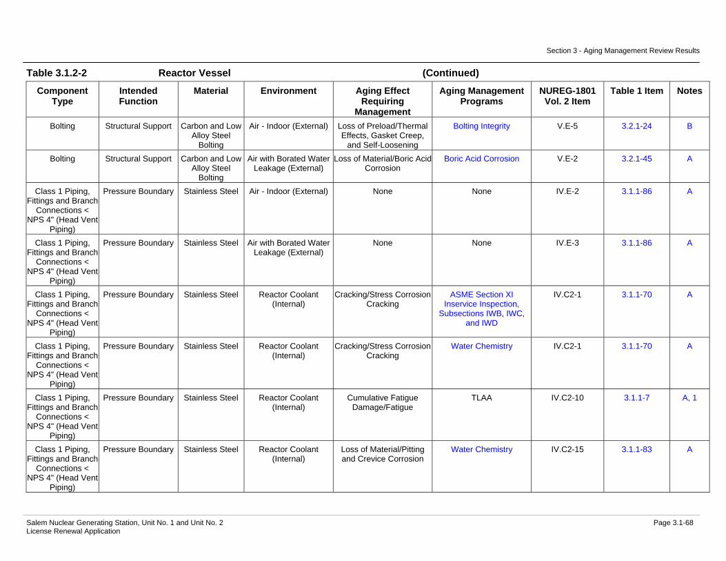
Section 3 - Aging Management Review Results
Salem Nuclear Generating Station, Unit No. 1 and Unit No. 2 Page 3.1-68 License Renewal Application
Table 3.1.2-2 Reactor Vessel (Continued)
Component Type
Intended Function
Material Environment Aging Effect Requiring
Management
Aging Management Programs
NUREG-1801 Vol. 2 Item
Table 1 Item Notes
Bolting Structural Support Carbon and Low Alloy Steel
Bolting
Air - Indoor (External) Loss of Preload/Thermal Effects, Gasket Creep,
and Self-Loosening
Bolting Integrity V.E-5 3.2.1-24 B
Bolting Structural Support Carbon and Low Alloy Steel
Bolting
Air with Borated Water Leakage (External)
Loss of Material/Boric Acid Corrosion
Boric Acid Corrosion V.E-2 3.2.1-45 A
Class 1 Piping, Fittings and Branch
Connections < NPS 4" (Head Vent
Piping)
Pressure Boundary Stainless Steel Air - Indoor (External) None None IV.E-2 3.1.1-86 A
Class 1 Piping, Fittings and Branch
Connections < NPS 4" (Head Vent
Piping)
Pressure Boundary Stainless Steel Air with Borated Water Leakage (External)
None None IV.E-3 3.1.1-86 A
Class 1 Piping, Fittings and Branch
Connections < NPS 4" (Head Vent
Piping)
Pressure Boundary Stainless Steel Reactor Coolant (Internal)
Cracking/Stress Corrosion Cracking
ASME Section XI Inservice Inspection,
Subsections IWB, IWC, and IWD
IV.C2-1 3.1.1-70 A
Class 1 Piping, Fittings and Branch
Connections < NPS 4" (Head Vent
Piping)
Pressure Boundary Stainless Steel Reactor Coolant (Internal)
Cracking/Stress Corrosion Cracking
Water Chemistry IV.C2-1 3.1.1-70 A
Class 1 Piping, Fittings and Branch
Connections < NPS 4" (Head Vent
Piping)
Pressure Boundary Stainless Steel Reactor Coolant (Internal)
Cumulative Fatigue Damage/Fatigue
TLAA IV.C2-10 3.1.1-7 A, 1
Class 1 Piping, Fittings and Branch
Connections < NPS 4" (Head Vent
Piping)
Pressure Boundary Stainless Steel Reactor Coolant (Internal)
Loss of Material/Pitting and Crevice Corrosion
Water Chemistry IV.C2-15 3.1.1-83 A
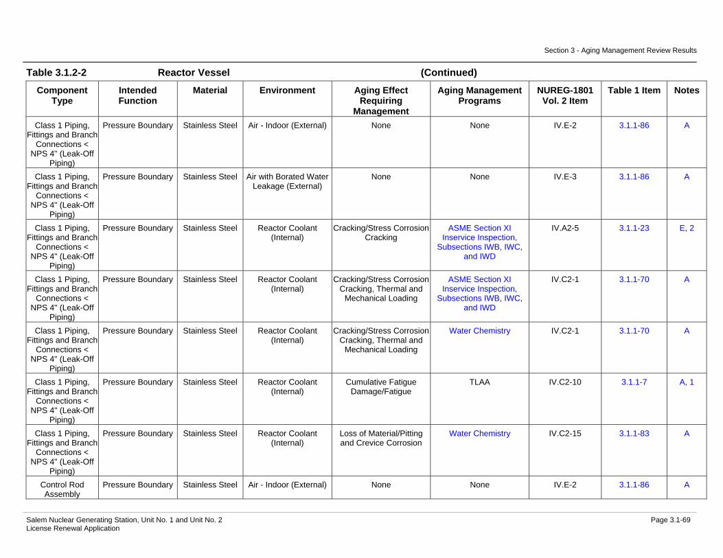
Section 3 - Aging Management Review Results
Salem Nuclear Generating Station, Unit No. 1 and Unit No. 2 Page 3.1-69 License Renewal Application
Table 3.1.2-2 Reactor Vessel (Continued)
Component Type
Intended Function
Material Environment Aging Effect Requiring
Management
Aging Management Programs
NUREG-1801 Vol. 2 Item
Table 1 Item Notes
Class 1 Piping, Fittings and Branch
Connections < NPS 4" (Leak-Off
Piping)
Pressure Boundary Stainless Steel Air - Indoor (External) None None IV.E-2 3.1.1-86 A
Class 1 Piping, Fittings and Branch
Connections < NPS 4" (Leak-Off
Piping)
Pressure Boundary Stainless Steel Air with Borated Water Leakage (External)
None None IV.E-3 3.1.1-86 A
Class 1 Piping, Fittings and Branch
Connections < NPS 4" (Leak-Off
Piping)
Pressure Boundary Stainless Steel Reactor Coolant (Internal)
Cracking/Stress Corrosion Cracking
ASME Section XI Inservice Inspection,
Subsections IWB, IWC, and IWD
IV.A2-5 3.1.1-23 E, 2
Class 1 Piping, Fittings and Branch
Connections < NPS 4" (Leak-Off
Piping)
Pressure Boundary Stainless Steel Reactor Coolant (Internal)
Cracking/Stress Corrosion Cracking, Thermal and
Mechanical Loading
ASME Section XI Inservice Inspection,
Subsections IWB, IWC, and IWD
IV.C2-1 3.1.1-70 A
Class 1 Piping, Fittings and Branch
Connections < NPS 4" (Leak-Off
Piping)
Pressure Boundary Stainless Steel Reactor Coolant (Internal)
Cracking/Stress Corrosion Cracking, Thermal and
Mechanical Loading
Water Chemistry IV.C2-1 3.1.1-70 A
Class 1 Piping, Fittings and Branch
Connections < NPS 4" (Leak-Off
Piping)
Pressure Boundary Stainless Steel Reactor Coolant (Internal)
Cumulative Fatigue Damage/Fatigue
TLAA IV.C2-10 3.1.1-7 A, 1
Class 1 Piping, Fittings and Branch
Connections < NPS 4" (Leak-Off
Piping)
Pressure Boundary Stainless Steel Reactor Coolant (Internal)
Loss of Material/Pitting and Crevice Corrosion
Water Chemistry IV.C2-15 3.1.1-83 A
Control Rod Assembly
Pressure Boundary Stainless Steel Air - Indoor (External) None None IV.E-2 3.1.1-86 A

Section 3 - Aging Management Review Results
Salem Nuclear Generating Station, Unit No. 1 and Unit No. 2 Page 3.1-70 License Renewal Application
Table 3.1.2-2 Reactor Vessel (Continued)
Component Type
Intended Function
Material Environment Aging Effect Requiring
Management
Aging Management Programs
NUREG-1801 Vol. 2 Item
Table 1 Item Notes
Control Rod Assembly
Pressure Boundary Stainless Steel Air with Borated Water Leakage (External)
None None IV.E-3 3.1.1-86 C
Control Rod Assembly
Pressure Boundary Stainless Steel Reactor Coolant (Internal)
Cracking/Stress Corrosion Cracking
ASME Section XI Inservice Inspection,
Subsections IWB, IWC, and IWD
IV.A2-11 3.1.1-34 A
Control Rod Assembly
Pressure Boundary Stainless Steel Reactor Coolant (Internal)
Cracking/Stress Corrosion Cracking
Water Chemistry IV.A2-11 3.1.1-34 A
Control Rod Assembly
Pressure Boundary Stainless Steel Reactor Coolant (Internal)
Cumulative Fatigue Damage/Fatigue
TLAA IV.A2-21 3.1.1-9 A, 1
Control Rod Assembly
Pressure Boundary Stainless Steel Reactor Coolant (Internal)
Loss of Material/Pitting and Crevice Corrosion
Water Chemistry IV.A2-14 3.1.1-83 C
Nozzle (BMI) Pressure Boundary Nickel Alloy Air - Indoor (External) None None V.F-11 3.2.1-53 C Nozzle (BMI) Pressure Boundary Nickel Alloy Air with Borated Water
Leakage (External) None None G, 3
Nozzle (BMI) Pressure Boundary Nickel Alloy Reactor Coolant (Internal)
Cracking/Stress Corrosion Cracking
ASME Section XI Inservice Inspection,
Subsections IWB, IWC, and IWD
IV.A2-19 3.1.1-31 A
Nozzle (BMI) Pressure Boundary Nickel Alloy Reactor Coolant (Internal)
Cracking/Stress Corrosion Cracking
Nickel Alloy Aging Management Program
IV.A2-19 3.1.1-31 A
Nozzle (BMI) Pressure Boundary Nickel Alloy Reactor Coolant (Internal)
Cracking/Stress Corrosion Cracking
Water Chemistry IV.A2-19 3.1.1-31 A
Nozzle (BMI) Pressure Boundary Nickel Alloy Reactor Coolant (Internal)
Cumulative Fatigue Damage/Fatigue
TLAA IV.A2-21 3.1.1-9 A, 1
Nozzle (BMI) Pressure Boundary Nickel Alloy Reactor Coolant (Internal)
Loss of Material/Pitting and Crevice Corrosion
Water Chemistry IV.A2-14 3.1.1-83 A
Nozzle (CRDM) Pressure Boundary Nickel Alloy Air - Indoor (External) None None V.F-11 3.2.1-53 C Nozzle (CRDM) Pressure Boundary Nickel Alloy Air with Borated Water
Leakage (External) None None G, 3
Nozzle (CRDM) Pressure Boundary Nickel Alloy Reactor Coolant (Internal)
Cracking/Stress Corrosion Cracking
ASME Section XI Inservice Inspection,
Subsections IWB, IWC, and IWD
IV.A2-9 3.1.1-65 A
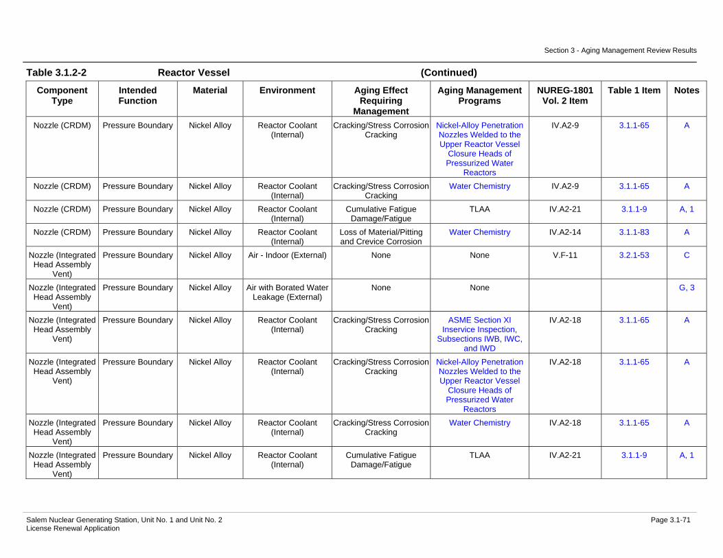
Section 3 - Aging Management Review Results
Salem Nuclear Generating Station, Unit No. 1 and Unit No. 2 Page 3.1-71 License Renewal Application
Table 3.1.2-2 Reactor Vessel (Continued)
Component Type
Intended Function
Material Environment Aging Effect Requiring
Management
Aging Management Programs
NUREG-1801 Vol. 2 Item
Table 1 Item Notes
Nozzle (CRDM) Pressure Boundary Nickel Alloy Reactor Coolant (Internal)
Cracking/Stress Corrosion Cracking
Nickel-Alloy Penetration Nozzles Welded to the Upper Reactor Vessel
Closure Heads of Pressurized Water
Reactors
IV.A2-9 3.1.1-65 A
Nozzle (CRDM) Pressure Boundary Nickel Alloy Reactor Coolant (Internal)
Cracking/Stress Corrosion Cracking
Water Chemistry IV.A2-9 3.1.1-65 A
Nozzle (CRDM) Pressure Boundary Nickel Alloy Reactor Coolant (Internal)
Cumulative Fatigue Damage/Fatigue
TLAA IV.A2-21 3.1.1-9 A, 1
Nozzle (CRDM) Pressure Boundary Nickel Alloy Reactor Coolant (Internal)
Loss of Material/Pitting and Crevice Corrosion
Water Chemistry IV.A2-14 3.1.1-83 A
Nozzle (Integrated Head Assembly
Vent)
Pressure Boundary Nickel Alloy Air - Indoor (External) None None V.F-11 3.2.1-53 C
Nozzle (Integrated Head Assembly
Vent)
Pressure Boundary Nickel Alloy Air with Borated Water Leakage (External)
None None G, 3
Nozzle (Integrated Head Assembly
Vent)
Pressure Boundary Nickel Alloy Reactor Coolant (Internal)
Cracking/Stress Corrosion Cracking
ASME Section XI Inservice Inspection,
Subsections IWB, IWC, and IWD
IV.A2-18 3.1.1-65 A
Nozzle (Integrated Head Assembly
Vent)
Pressure Boundary Nickel Alloy Reactor Coolant (Internal)
Cracking/Stress Corrosion Cracking
Nickel-Alloy Penetration Nozzles Welded to the Upper Reactor Vessel
Closure Heads of Pressurized Water
Reactors
IV.A2-18 3.1.1-65 A
Nozzle (Integrated Head Assembly
Vent)
Pressure Boundary Nickel Alloy Reactor Coolant (Internal)
Cracking/Stress Corrosion Cracking
Water Chemistry IV.A2-18 3.1.1-65 A
Nozzle (Integrated Head Assembly
Vent)
Pressure Boundary Nickel Alloy Reactor Coolant (Internal)
Cumulative Fatigue Damage/Fatigue
TLAA IV.A2-21 3.1.1-9 A, 1

Section 3 - Aging Management Review Results
Salem Nuclear Generating Station, Unit No. 1 and Unit No. 2 Page 3.1-72 License Renewal Application
Table 3.1.2-2 Reactor Vessel (Continued)
Component Type
Intended Function
Material Environment Aging Effect Requiring
Management
Aging Management Programs
NUREG-1801 Vol. 2 Item
Table 1 Item Notes
Nozzle (Integrated Head Assembly
Vent)
Pressure Boundary Nickel Alloy Reactor Coolant (Internal)
Loss of Material/Pitting and Crevice Corrosion
Water Chemistry IV.A2-14 3.1.1-83 A
Nozzle (Primary) Pressure Boundary Carbon or Low Alloy Steel with Stainless Steel
Cladding
Air - Indoor (External) Loss of Material/General Corrosion
External Surfaces Monitoring
V.E-7 3.2.1-31 A
Nozzle (Primary) Pressure Boundary Carbon or Low Alloy Steel with Stainless Steel
Cladding
Air with Borated Water Leakage (External)
Loss of Material/Boric Acid Corrosion
Boric Acid Corrosion IV.A2-13 3.1.1-58 A
Nozzle (Primary) Pressure Boundary Carbon or Low Alloy Steel with Stainless Steel
Cladding
Reactor Coolant Cracking/Stress Corrosion Cracking
ASME Section XI Inservice Inspection,
Subsections IWB, IWC, and IWD
IV.A2-15 3.1.1-69 A
Nozzle (Primary) Pressure Boundary Carbon or Low Alloy Steel with Stainless Steel
Cladding
Reactor Coolant Cracking/Stress Corrosion Cracking
Water Chemistry IV.A2-15 3.1.1-69 A
Nozzle (Primary) Pressure Boundary Carbon or Low Alloy Steel with Stainless Steel
Cladding
Reactor Coolant Cumulative Fatigue Damage/Fatigue
TLAA IV.A2-21 3.1.1-9 A, 1
Nozzle (Primary) Pressure Boundary Carbon or Low Alloy Steel with Stainless Steel
Cladding
Reactor Coolant Loss of Material/Pitting and Crevice Corrosion
Water Chemistry IV.A2-14 3.1.1-83 A
Nozzle (RVLIS) Pressure Boundary Nickel Alloy Air - Indoor (External) None None V.F-11 3.2.1-53 C Nozzle (RVLIS) Pressure Boundary Nickel Alloy Air with Borated Water
Leakage (External) None None G, 3
Nozzle (RVLIS) Pressure Boundary Nickel Alloy Reactor Coolant (Internal)
Cracking/Stress Corrosion Cracking
ASME Section XI Inservice Inspection,
Subsections IWB, IWC, and IWD
IV.A2-18 3.1.1-65 A
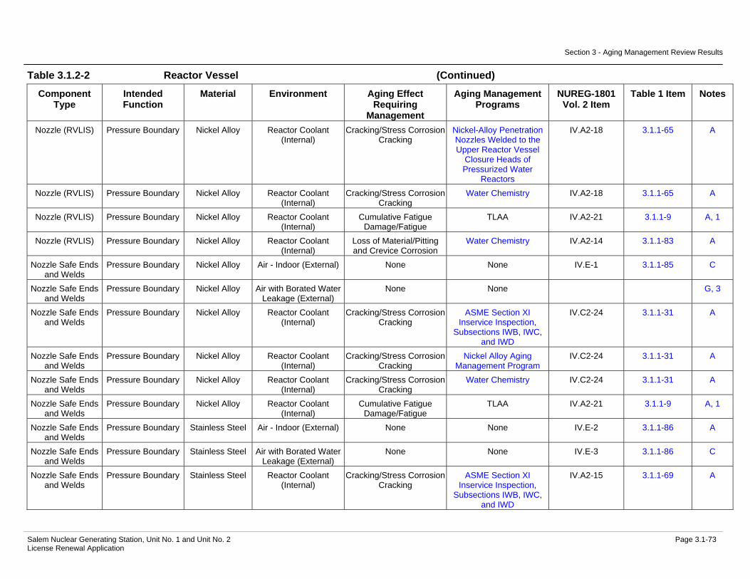
Section 3 - Aging Management Review Results
Salem Nuclear Generating Station, Unit No. 1 and Unit No. 2 Page 3.1-73 License Renewal Application
Table 3.1.2-2 Reactor Vessel (Continued)
Component Type
Intended Function
Material Environment Aging Effect Requiring
Management
Aging Management Programs
NUREG-1801 Vol. 2 Item
Table 1 Item Notes
Nozzle (RVLIS) Pressure Boundary Nickel Alloy Reactor Coolant (Internal)
Cracking/Stress Corrosion Cracking
Nickel-Alloy Penetration Nozzles Welded to the Upper Reactor Vessel
Closure Heads of Pressurized Water
Reactors
IV.A2-18 3.1.1-65 A
Nozzle (RVLIS) Pressure Boundary Nickel Alloy Reactor Coolant (Internal)
Cracking/Stress Corrosion Cracking
Water Chemistry IV.A2-18 3.1.1-65 A
Nozzle (RVLIS) Pressure Boundary Nickel Alloy Reactor Coolant (Internal)
Cumulative Fatigue Damage/Fatigue
TLAA IV.A2-21 3.1.1-9 A, 1
Nozzle (RVLIS) Pressure Boundary Nickel Alloy Reactor Coolant (Internal)
Loss of Material/Pitting and Crevice Corrosion
Water Chemistry IV.A2-14 3.1.1-83 A
Nozzle Safe Ends and Welds
Pressure Boundary Nickel Alloy Air - Indoor (External) None None IV.E-1 3.1.1-85 C
Nozzle Safe Ends and Welds
Pressure Boundary Nickel Alloy Air with Borated Water Leakage (External)
None None G, 3
Nozzle Safe Ends and Welds
Pressure Boundary Nickel Alloy Reactor Coolant (Internal)
Cracking/Stress Corrosion Cracking
ASME Section XI Inservice Inspection,
Subsections IWB, IWC, and IWD
IV.C2-24 3.1.1-31 A
Nozzle Safe Ends and Welds
Pressure Boundary Nickel Alloy Reactor Coolant (Internal)
Cracking/Stress Corrosion Cracking
Nickel Alloy Aging Management Program
IV.C2-24 3.1.1-31 A
Nozzle Safe Ends and Welds
Pressure Boundary Nickel Alloy Reactor Coolant (Internal)
Cracking/Stress Corrosion Cracking
Water Chemistry IV.C2-24 3.1.1-31 A
Nozzle Safe Ends and Welds
Pressure Boundary Nickel Alloy Reactor Coolant (Internal)
Cumulative Fatigue Damage/Fatigue
TLAA IV.A2-21 3.1.1-9 A, 1
Nozzle Safe Ends and Welds
Pressure Boundary Stainless Steel Air - Indoor (External) None None IV.E-2 3.1.1-86 A
Nozzle Safe Ends and Welds
Pressure Boundary Stainless Steel Air with Borated Water Leakage (External)
None None IV.E-3 3.1.1-86 C
Nozzle Safe Ends and Welds
Pressure Boundary Stainless Steel Reactor Coolant (Internal)
Cracking/Stress Corrosion Cracking
ASME Section XI Inservice Inspection,
Subsections IWB, IWC, and IWD
IV.A2-15 3.1.1-69 A
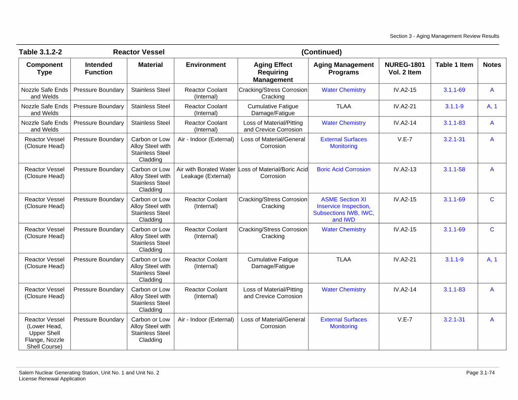
Section 3 - Aging Management Review Results
Salem Nuclear Generating Station, Unit No. 1 and Unit No. 2 Page 3.1-74 License Renewal Application
Table 3.1.2-2 Reactor Vessel (Continued)
Component Type
Intended Function
Material Environment Aging Effect Requiring
Management
Aging Management Programs
NUREG-1801 Vol. 2 Item
Table 1 Item Notes
Nozzle Safe Ends and Welds
Pressure Boundary Stainless Steel Reactor Coolant (Internal)
Cracking/Stress Corrosion Cracking
Water Chemistry IV.A2-15 3.1.1-69 A
Nozzle Safe Ends and Welds
Pressure Boundary Stainless Steel Reactor Coolant (Internal)
Cumulative Fatigue Damage/Fatigue
TLAA IV.A2-21 3.1.1-9 A, 1
Nozzle Safe Ends and Welds
Pressure Boundary Stainless Steel Reactor Coolant (Internal)
Loss of Material/Pitting and Crevice Corrosion
Water Chemistry IV.A2-14 3.1.1-83 A
Reactor Vessel (Closure Head)
Pressure Boundary Carbon or Low Alloy Steel with Stainless Steel
Cladding
Air - Indoor (External) Loss of Material/General Corrosion
External Surfaces Monitoring
V.E-7 3.2.1-31 A
Reactor Vessel (Closure Head)
Pressure Boundary Carbon or Low Alloy Steel with Stainless Steel
Cladding
Air with Borated Water Leakage (External)
Loss of Material/Boric Acid Corrosion
Boric Acid Corrosion IV.A2-13 3.1.1-58 A
Reactor Vessel (Closure Head)
Pressure Boundary Carbon or Low Alloy Steel with Stainless Steel
Cladding
Reactor Coolant (Internal)
Cracking/Stress Corrosion Cracking
ASME Section XI Inservice Inspection,
Subsections IWB, IWC, and IWD
IV.A2-15 3.1.1-69 C
Reactor Vessel (Closure Head)
Pressure Boundary Carbon or Low Alloy Steel with Stainless Steel
Cladding
Reactor Coolant (Internal)
Cracking/Stress Corrosion Cracking
Water Chemistry IV.A2-15 3.1.1-69 C
Reactor Vessel (Closure Head)
Pressure Boundary Carbon or Low Alloy Steel with Stainless Steel
Cladding
Reactor Coolant (Internal)
Cumulative Fatigue Damage/Fatigue
TLAA IV.A2-21 3.1.1-9 A, 1
Reactor Vessel (Closure Head)
Pressure Boundary Carbon or Low Alloy Steel with Stainless Steel
Cladding
Reactor Coolant (Internal)
Loss of Material/Pitting and Crevice Corrosion
Water Chemistry IV.A2-14 3.1.1-83 A
Reactor Vessel (Lower Head, Upper Shell
Flange, Nozzle Shell Course)
Pressure Boundary Carbon or Low Alloy Steel with Stainless Steel
Cladding
Air - Indoor (External) Loss of Material/General Corrosion
External Surfaces Monitoring
V.E-7 3.2.1-31 A

Section 3 - Aging Management Review Results
Salem Nuclear Generating Station, Unit No. 1 and Unit No. 2 Page 3.1-75 License Renewal Application
Table 3.1.2-2 Reactor Vessel (Continued)
Component Type
Intended Function
Material Environment Aging Effect Requiring
Management
Aging Management Programs
NUREG-1801 Vol. 2 Item
Table 1 Item Notes
Reactor Vessel (Lower Head, Upper Shell
Flange, Nozzle Shell Course)
Pressure Boundary Carbon or Low Alloy Steel with Stainless Steel
Cladding
Air with Borated Water Leakage (External)
Loss of Material/Boric Acid Corrosion
Boric Acid Corrosion IV.A2-13 3.1.1-58 A
Reactor Vessel (Lower Head, Upper Shell
Flange, Nozzle Shell Course)
Pressure Boundary Carbon or Low Alloy Steel with Stainless Steel
Cladding
Reactor Coolant Cracking/Stress Corrosion Cracking
ASME Section XI Inservice Inspection,
Subsections IWB, IWC, and IWD
IV.A2-15 3.1.1-69 C
Reactor Vessel (Lower Head, Upper Shell
Flange, Nozzle Shell Course)
Pressure Boundary Carbon or Low Alloy Steel with Stainless Steel
Cladding
Reactor Coolant Cracking/Stress Corrosion Cracking
Water Chemistry IV.A2-15 3.1.1-69 C
Reactor Vessel (Lower Head, Upper Shell
Flange, Nozzle Shell Course)
Pressure Boundary Carbon or Low Alloy Steel with Stainless Steel
Cladding
Reactor Coolant Cumulative Fatigue Damage/Fatigue
TLAA IV.A2-21 3.1.1-9 A, 1
Reactor Vessel (Lower Head, Upper Shell
Flange, Nozzle Shell Course)
Pressure Boundary Carbon or Low Alloy Steel with Stainless Steel
Cladding
Reactor Coolant Loss of Material/Pitting and Crevice Corrosion
Water Chemistry IV.A2-14 3.1.1-83 A
Reactor Vessel (Nozzle Supports)
Structural Support Low Alloy Steel Air - Indoor (External) Loss of Material/General Corrosion
External Surfaces Monitoring
V.E-7 3.2.1-31 A
Reactor Vessel (Nozzle Supports)
Structural Support Low Alloy Steel Air with Borated Water Leakage (External)
Loss of Material/Boric Acid Corrosion
Boric Acid Corrosion IV.A2-13 3.1.1-58 A
Reactor Vessel (Upper Shell,
Intermediate Shell, Lower Shell, and
Welds)
Pressure Boundary Carbon or Low Alloy Steel with Stainless Steel
Cladding
Air - Indoor (External) Loss of Material/General Corrosion
External Surfaces Monitoring
V.E-7 3.2.1-31 A

Section 3 - Aging Management Review Results
Salem Nuclear Generating Station, Unit No. 1 and Unit No. 2 Page 3.1-76 License Renewal Application
Table 3.1.2-2 Reactor Vessel (Continued)
Component Type
Intended Function
Material Environment Aging Effect Requiring
Management
Aging Management Programs
NUREG-1801 Vol. 2 Item
Table 1 Item Notes
Reactor Vessel (Upper Shell,
Intermediate Shell, Lower Shell, and
Welds)
Pressure Boundary Carbon or Low Alloy Steel with Stainless Steel
Cladding
Air with Borated Water Leakage (External)
Loss of Material/Boric Acid Corrosion
Boric Acid Corrosion IV.A2-13 3.1.1-58 A
Reactor Vessel (Upper Shell,
Intermediate Shell, Lower Shell, and
Welds)
Pressure Boundary Carbon or Low Alloy Steel with Stainless Steel
Cladding
Reactor Coolant and Neutron Flux (Internal)
Cracking/Stress Corrosion Cracking
ASME Section XI Inservice Inspection,
Subsections IWB, IWC, and IWD
IV.A2-15 3.1.1-69 C
Reactor Vessel (Upper Shell,
Intermediate Shell, Lower Shell, and
Welds)
Pressure Boundary Carbon or Low Alloy Steel with Stainless Steel
Cladding
Reactor Coolant and Neutron Flux (Internal)
Cracking/Stress Corrosion Cracking
Water Chemistry IV.A2-15 3.1.1-69 C
Reactor Vessel (Upper Shell,
Intermediate Shell, Lower Shell, and
Welds)
Pressure Boundary Carbon or Low Alloy Steel with Stainless Steel
Cladding
Reactor Coolant and Neutron Flux (Internal)
Cumulative Fatigue Damage/Fatigue
TLAA IV.A2-21 3.1.1-9 A, 1
Reactor Vessel (Upper Shell,
Intermediate Shell, Lower Shell, and
Welds)
Pressure Boundary Carbon or Low Alloy Steel with Stainless Steel
Cladding
Reactor Coolant and Neutron Flux (Internal)
Loss of Fracture Toughness/Neutron
Irradiation Embrittlement
Reactor Vessel Surveillance
IV.A2-24 3.1.1-18 A
Reactor Vessel (Upper Shell,
Intermediate Shell, Lower Shell, and
Welds)
Pressure Boundary Carbon or Low Alloy Steel with Stainless Steel
Cladding
Reactor Coolant and Neutron Flux (Internal)
Loss of Fracture Toughness/Neutron
Irradiation Embrittlement
TLAA IV.A2-23 3.1.1-17 A, 1
Reactor Vessel (Upper Shell,
Intermediate Shell, Lower Shell, and
Welds)
Pressure Boundary Carbon or Low Alloy Steel with Stainless Steel
Cladding
Reactor Coolant and Neutron Flux (Internal)
Loss of Material/Pitting and Crevice Corrosion
Water Chemistry IV.A2-14 3.1.1-83 A
Restricting Orifices Pressure Boundary Stainless Steel Air - Indoor (External) None None IV.E-2 3.1.1-86 A

Section 3 - Aging Management Review Results
Salem Nuclear Generating Station, Unit No. 1 and Unit No. 2 Page 3.1-77 License Renewal Application
Table 3.1.2-2 Reactor Vessel (Continued)
Component Type
Intended Function
Material Environment Aging Effect Requiring
Management
Aging Management Programs
NUREG-1801 Vol. 2 Item
Table 1 Item Notes
Restricting Orifices Pressure Boundary Stainless Steel Air with Borated Water Leakage (External)
None None IV.E-3 3.1.1-86 A
Restricting Orifices Pressure Boundary Stainless Steel Reactor Coolant (Internal)
Cracking/Stress Corrosion Cracking
ASME Section XI Inservice Inspection,
Subsections IWB, IWC, and IWD
IV.C2-2 3.1.1-68 A
Restricting Orifices Pressure Boundary Stainless Steel Reactor Coolant (Internal)
Cracking/Stress Corrosion Cracking
Water Chemistry IV.C2-2 3.1.1-68 A
Restricting Orifices Pressure Boundary Stainless Steel Reactor Coolant (Internal)
Cumulative Fatigue Damage/Fatigue
TLAA IV.C2-25 3.1.1-8 A, 1
Restricting Orifices Pressure Boundary Stainless Steel Reactor Coolant (Internal)
Loss of Material/Pitting and Crevice Corrosion
Water Chemistry IV.C2-15 3.1.1-83 A
Restricting Orifices Throttle Stainless Steel Air - Indoor (External) None None IV.E-2 3.1.1-86 A Restricting Orifices Throttle Stainless Steel Air with Borated Water
Leakage (External) None None IV.E-3 3.1.1-86 A
Restricting Orifices Throttle Stainless Steel Reactor Coolant (Internal)
Cracking/Stress Corrosion Cracking
ASME Section XI Inservice Inspection,
Subsections IWB, IWC, and IWD
IV.C2-2 3.1.1-68 A
Restricting Orifices Throttle Stainless Steel Reactor Coolant (Internal)
Cracking/Stress Corrosion Cracking
Water Chemistry IV.C2-2 3.1.1-68 A
Restricting Orifices Throttle Stainless Steel Reactor Coolant (Internal)
Cumulative Fatigue Damage/Fatigue
TLAA IV.C2-25 3.1.1-8 A, 1
Restricting Orifices Throttle Stainless Steel Reactor Coolant (Internal)
Loss of Material/Pitting and Crevice Corrosion
Water Chemistry IV.C2-15 3.1.1-83 A
Steel components: All structural steel
Structural Support Carbon Steel Air - Indoor (External) Loss of Material/General Corrosion
External Surfaces Monitoring
V.E-7 3.2.1-31 A
Steel components: All structural steel
Structural Support Carbon Steel Air with Borated Water Leakage (External)
Loss of Material/Boric Acid Corrosion
Boric Acid Corrosion IV.A2-13 3.1.1-58 A
Valve Body Pressure Boundary Stainless Steel Air - Indoor (External) None None IV.E-2 3.1.1-86 A Valve Body Pressure Boundary Stainless Steel Air with Borated Water
Leakage (External) None None IV.E-3 3.1.1-86 A

Section 3 - Aging Management Review Results
Salem Nuclear Generating Station, Unit No. 1 and Unit No. 2 Page 3.1-78 License Renewal Application
Table 3.1.2-2 Reactor Vessel (Continued)
Component Type
Intended Function
Material Environment Aging Effect Requiring
Management
Aging Management Programs
NUREG-1801 Vol. 2 Item
Table 1 Item Notes
Valve Body Pressure Boundary Stainless Steel Reactor Coolant (Internal)
Cracking/Stress Corrosion Cracking
ASME Section XI Inservice Inspection,
Subsections IWB, IWC, and IWD
IV.C2-5 3.1.1-68 A
Valve Body Pressure Boundary Stainless Steel Reactor Coolant (Internal)
Cracking/Stress Corrosion Cracking
Water Chemistry IV.C2-5 3.1.1-68 A
Valve Body Pressure Boundary Stainless Steel Reactor Coolant (Internal)
Cumulative Fatigue Damage/Fatigue
TLAA IV.C2-10 3.1.1-7 A, 1
Valve Body Pressure Boundary Stainless Steel Reactor Coolant (Internal)
Loss of Material/Pitting and Crevice Corrosion
Water Chemistry IV.C2-15 3.1.1-83 A
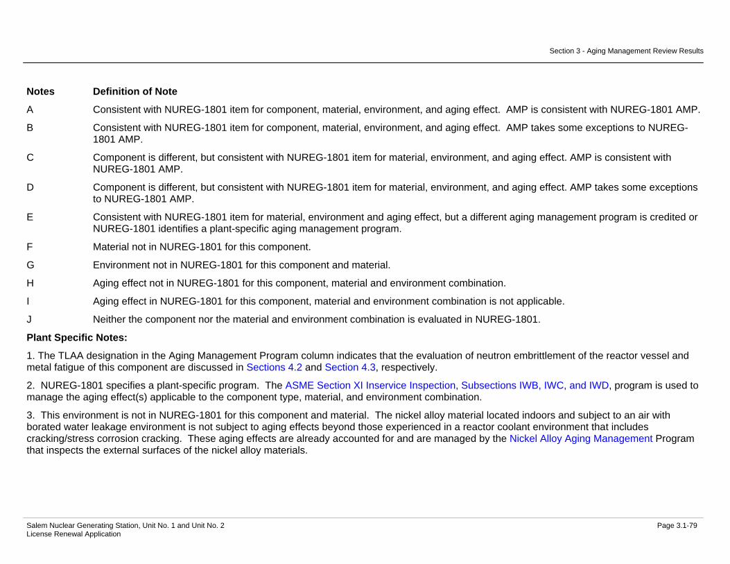
Section 3 - Aging Management Review Results
Salem Nuclear Generating Station, Unit No. 1 and Unit No. 2 Page 3.1-79 License Renewal Application
Notes Definition of Note
A Consistent with NUREG-1801 item for component, material, environment, and aging effect. AMP is consistent with NUREG-1801 AMP.
B Consistent with NUREG-1801 item for component, material, environment, and aging effect. AMP takes some exceptions to NUREG-1801 AMP.
C Component is different, but consistent with NUREG-1801 item for material, environment, and aging effect. AMP is consistent with NUREG-1801 AMP.
D Component is different, but consistent with NUREG-1801 item for material, environment, and aging effect. AMP takes some exceptions to NUREG-1801 AMP.
E Consistent with NUREG-1801 item for material, environment and aging effect, but a different aging management program is credited or NUREG-1801 identifies a plant-specific aging management program.
F Material not in NUREG-1801 for this component.
G Environment not in NUREG-1801 for this component and material.
H Aging effect not in NUREG-1801 for this component, material and environment combination.
I Aging effect in NUREG-1801 for this component, material and environment combination is not applicable.
J Neither the component nor the material and environment combination is evaluated in NUREG-1801.
Plant Specific Notes:
1. The TLAA designation in the Aging Management Program column indicates that the evaluation of neutron embrittlement of the reactor vessel and metal fatigue of this component are discussed in Sections 4.2 and Section 4.3, respectively.
2. NUREG-1801 specifies a plant-specific program. The ASME Section XI Inservice Inspection, Subsections IWB, IWC, and IWD, program is used to manage the aging effect(s) applicable to the component type, material, and environment combination.
3. This environment is not in NUREG-1801 for this component and material. The nickel alloy material located indoors and subject to an air with borated water leakage environment is not subject to aging effects beyond those experienced in a reactor coolant environment that includes cracking/stress corrosion cracking. These aging effects are already accounted for and are managed by the Nickel Alloy Aging Management Program that inspects the external surfaces of the nickel alloy materials.

Section 3 - Aging Management Review Results
Salem Nuclear Generating Station, Unit No. 1 and Unit No. 2 Page 3.1-80 License Renewal Application
Table 3.1.2-3 Reactor Vessel Internals
Summary of Aging Management Evaluation
Table 3.1.2-3 Reactor Vessel Internals
Component Type
Intended Function
Material Environment Aging Effect Requiring
Management
Aging Management Programs
NUREG-1801 Vol. 2 Item
Table 1 Item Notes
Control Rod Assembly
None - Short Lived Not Applicable Not Applicable Not Applicable Not Applicable 2
Core Barrel (lower) Structural Support to maintain core
configuration and flow distribution
Stainless Steel Reactor Coolant and Neutron Flux
Changes in Dimensions/Void Swelling
PWR Vessel Internals IV.B2-7 3.1.1-33 A, 1
Core Barrel (lower) Structural Support to maintain core
configuration and flow distribution
Stainless Steel Reactor Coolant and Neutron Flux
Cracking/Stress Corrosion Cracking, Irradiation-
Assisted Stress Corrosion Cracking
PWR Vessel Internals IV.B2-8 3.1.1-30 A, 1
Core Barrel (lower) Structural Support to maintain core
configuration and flow distribution
Stainless Steel Reactor Coolant and Neutron Flux
Cracking/Stress Corrosion Cracking, Irradiation-
Assisted Stress Corrosion Cracking
Water Chemistry IV.B2-8 3.1.1-30 A
Core Barrel (lower) Structural Support to maintain core
configuration and flow distribution
Stainless Steel Reactor Coolant and Neutron Flux
Loss of Fracture Toughness/Neutron
Irradiation Embrittlement, Void Swelling
PWR Vessel Internals IV.B2-9 3.1.1-22 A, 1
Core Barrel (lower) Structural Support to maintain core
configuration and flow distribution
Stainless Steel Reactor Coolant and Neutron Flux
Loss of Material/Pitting and Crevice Corrosion
Water Chemistry IV.B2-32 3.1.1-83 A
Core Barrel (upper) Structural Support to maintain core
configuration and flow distribution
Stainless Steel Reactor Coolant and Neutron Flux
Changes in Dimensions/Void Swelling
PWR Vessel Internals IV.B2-7 3.1.1-33 A, 1

Section 3 - Aging Management Review Results
Salem Nuclear Generating Station, Unit No. 1 and Unit No. 2 Page 3.1-81 License Renewal Application
Table 3.1.2-3 Reactor Vessel Internals (Continued)
Component Type
Intended Function
Material Environment Aging Effect Requiring
Management
Aging Management Programs
NUREG-1801 Vol. 2 Item
Table 1 Item Notes
Core Barrel (upper) Structural Support to maintain core
configuration and flow distribution
Stainless Steel Reactor Coolant and Neutron Flux
Cracking/Stress Corrosion Cracking, Irradiation-
Assisted Stress Corrosion Cracking
PWR Vessel Internals IV.B2-8 3.1.1-30 A, 1
Core Barrel (upper) Structural Support to maintain core
configuration and flow distribution
Stainless Steel Reactor Coolant and Neutron Flux
Cracking/Stress Corrosion Cracking, Irradiation-
Assisted Stress Corrosion Cracking
Water Chemistry IV.B2-8 3.1.1-30 A
Core Barrel (upper) Structural Support to maintain core
configuration and flow distribution
Stainless Steel Reactor Coolant and Neutron Flux
Loss of Fracture Toughness/Neutron
Irradiation Embrittlement, Void Swelling
PWR Vessel Internals IV.B2-9 3.1.1-22 A, 1
Core Barrel (upper) Structural Support to maintain core
configuration and flow distribution
Stainless Steel Reactor Coolant and Neutron Flux
Loss of Material/Pitting and Crevice Corrosion
Water Chemistry IV.B2-32 3.1.1-83 A
Core Barrel Assembly
(alignment pins)
Structural Support to maintain core
configuration and flow distribution
Stainless Steel Reactor Coolant and Neutron Flux
Changes in Dimensions/Void Swelling
PWR Vessel Internals IV.B2-4 3.1.1-33 A, 1
Core Barrel Assembly
(alignment pins)
Structural Support to maintain core
configuration and flow distribution
Stainless Steel Reactor Coolant and Neutron Flux
Cracking/Stress Corrosion Cracking, Irradiation-
Assisted Stress Corrosion Cracking
PWR Vessel Internals IV.B2-10 3.1.1-30 A, 1
Core Barrel Assembly
(alignment pins)
Structural Support to maintain core
configuration and flow distribution
Stainless Steel Reactor Coolant and Neutron Flux
Cracking/Stress Corrosion Cracking, Irradiation-
Assisted Stress Corrosion Cracking
Water Chemistry IV.B2-10 3.1.1-30 A
Core Barrel Assembly
(alignment pins)
Structural Support to maintain core
configuration and flow distribution
Stainless Steel Reactor Coolant and Neutron Flux
Loss of Fracture Toughness/Neutron
Irradiation Embrittlement, Void Swelling
PWR Vessel Internals IV.B2-6 3.1.1-22 A, 1
Core Barrel Assembly
(alignment pins)
Structural Support to maintain core
configuration and flow distribution
Stainless Steel Reactor Coolant and Neutron Flux
Loss of Material/Pitting and Crevice Corrosion
Water Chemistry IV.B2-32 3.1.1-83 A

Section 3 - Aging Management Review Results
Salem Nuclear Generating Station, Unit No. 1 and Unit No. 2 Page 3.1-82 License Renewal Application
Table 3.1.2-3 Reactor Vessel Internals (Continued)
Component Type
Intended Function
Material Environment Aging Effect Requiring
Management
Aging Management Programs
NUREG-1801 Vol. 2 Item
Table 1 Item Notes
Core Barrel Assembly
(alignment pins)
Structural Support to maintain core
configuration and flow distribution
Stainless Steel Reactor Coolant and Neutron Flux
Loss of Preload/Stress Relaxation
PWR Vessel Internals IV.B2-5 3.1.1-27 A, 1
Core Barrel Assembly (baffle
bolt lock bars)
Structural Support to maintain core
configuration and flow distribution
Stainless Steel Reactor Coolant and Neutron Flux
Changes in Dimensions/Void Swelling
PWR Vessel Internals IV.B2-4 3.1.1-33 A, 1
Core Barrel Assembly (baffle
bolt lock bars)
Structural Support to maintain core
configuration and flow distribution
Stainless Steel Reactor Coolant and Neutron Flux
Cracking/Stress Corrosion Cracking, Irradiation-
Assisted Stress Corrosion Cracking
PWR Vessel Internals IV.B2-10 3.1.1-30 A, 1
Core Barrel Assembly (baffle
bolt lock bars)
Structural Support to maintain core
configuration and flow distribution
Stainless Steel Reactor Coolant and Neutron Flux
Cracking/Stress Corrosion Cracking, Irradiation-
Assisted Stress Corrosion Cracking
Water Chemistry IV.B2-10 3.1.1-30 A
Core Barrel Assembly (baffle
bolt lock bars)
Structural Support to maintain core
configuration and flow distribution
Stainless Steel Reactor Coolant and Neutron Flux
Loss of Fracture Toughness/Neutron
Irradiation Embrittlement, Void Swelling
PWR Vessel Internals IV.B2-6 3.1.1-22 A, 1
Core Barrel Assembly (baffle
bolt lock bars)
Structural Support to maintain core
configuration and flow distribution
Stainless Steel Reactor Coolant and Neutron Flux
Loss of Material/Pitting and Crevice Corrosion
Water Chemistry IV.B2-32 3.1.1-83 A
Core Barrel Assembly (baffle
bolt lock bars)
Structural Support to maintain core
configuration and flow distribution
Stainless Steel Reactor Coolant and Neutron Flux
Loss of Preload/Stress Relaxation
PWR Vessel Internals IV.B2-5 3.1.1-27 A, 1
Core Barrel Assembly (baffle
former assembly - plates)
Structural Support to maintain core
configuration and flow distribution
Stainless Steel Reactor Coolant and Neutron Flux
Changes in Dimensions/Void Swelling
PWR Vessel Internals IV.B2-1 3.1.1-33 A, 1
Core Barrel Assembly (baffle
former assembly - plates)
Structural Support to maintain core
configuration and flow distribution
Stainless Steel Reactor Coolant and Neutron Flux
Cracking/Stress Corrosion Cracking, Irradiation-
Assisted Stress Corrosion Cracking
PWR Vessel Internals IV.B2-2 3.1.1-30 A, 1
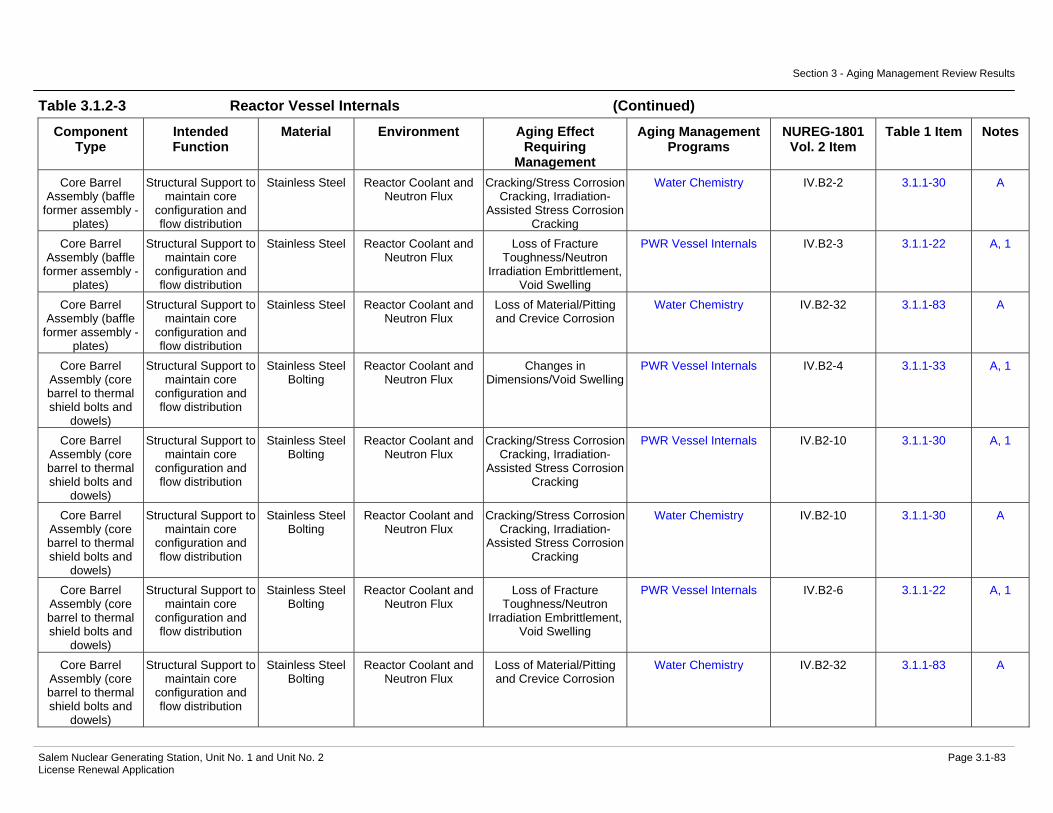
Section 3 - Aging Management Review Results
Salem Nuclear Generating Station, Unit No. 1 and Unit No. 2 Page 3.1-83 License Renewal Application
Table 3.1.2-3 Reactor Vessel Internals (Continued)
Component Type
Intended Function
Material Environment Aging Effect Requiring
Management
Aging Management Programs
NUREG-1801 Vol. 2 Item
Table 1 Item Notes
Core Barrel Assembly (baffle
former assembly - plates)
Structural Support to maintain core
configuration and flow distribution
Stainless Steel Reactor Coolant and Neutron Flux
Cracking/Stress Corrosion Cracking, Irradiation-
Assisted Stress Corrosion Cracking
Water Chemistry IV.B2-2 3.1.1-30 A
Core Barrel Assembly (baffle
former assembly - plates)
Structural Support to maintain core
configuration and flow distribution
Stainless Steel Reactor Coolant and Neutron Flux
Loss of Fracture Toughness/Neutron
Irradiation Embrittlement, Void Swelling
PWR Vessel Internals IV.B2-3 3.1.1-22 A, 1
Core Barrel Assembly (baffle
former assembly - plates)
Structural Support to maintain core
configuration and flow distribution
Stainless Steel Reactor Coolant and Neutron Flux
Loss of Material/Pitting and Crevice Corrosion
Water Chemistry IV.B2-32 3.1.1-83 A
Core Barrel Assembly (core barrel to thermal shield bolts and
dowels)
Structural Support to maintain core
configuration and flow distribution
Stainless Steel Bolting
Reactor Coolant and Neutron Flux
Changes in Dimensions/Void Swelling
PWR Vessel Internals IV.B2-4 3.1.1-33 A, 1
Core Barrel Assembly (core barrel to thermal shield bolts and
dowels)
Structural Support to maintain core
configuration and flow distribution
Stainless Steel Bolting
Reactor Coolant and Neutron Flux
Cracking/Stress Corrosion Cracking, Irradiation-
Assisted Stress Corrosion Cracking
PWR Vessel Internals IV.B2-10 3.1.1-30 A, 1
Core Barrel Assembly (core barrel to thermal shield bolts and
dowels)
Structural Support to maintain core
configuration and flow distribution
Stainless Steel Bolting
Reactor Coolant and Neutron Flux
Cracking/Stress Corrosion Cracking, Irradiation-
Assisted Stress Corrosion Cracking
Water Chemistry IV.B2-10 3.1.1-30 A
Core Barrel Assembly (core barrel to thermal shield bolts and
dowels)
Structural Support to maintain core
configuration and flow distribution
Stainless Steel Bolting
Reactor Coolant and Neutron Flux
Loss of Fracture Toughness/Neutron
Irradiation Embrittlement, Void Swelling
PWR Vessel Internals IV.B2-6 3.1.1-22 A, 1
Core Barrel Assembly (core barrel to thermal shield bolts and
dowels)
Structural Support to maintain core
configuration and flow distribution
Stainless Steel Bolting
Reactor Coolant and Neutron Flux
Loss of Material/Pitting and Crevice Corrosion
Water Chemistry IV.B2-32 3.1.1-83 A

Section 3 - Aging Management Review Results
Salem Nuclear Generating Station, Unit No. 1 and Unit No. 2 Page 3.1-84 License Renewal Application
Table 3.1.2-3 Reactor Vessel Internals (Continued)
Component Type
Intended Function
Material Environment Aging Effect Requiring
Management
Aging Management Programs
NUREG-1801 Vol. 2 Item
Table 1 Item Notes
Core Barrel Assembly (core barrel to thermal shield bolts and
dowels)
Structural Support to maintain core
configuration and flow distribution
Stainless Steel Bolting
Reactor Coolant and Neutron Flux
Loss of Preload/Stress Relaxation
PWR Vessel Internals IV.B2-5 3.1.1-27 A, 1
Core Barrel Assembly (flange)
Structural Support to maintain core
configuration and flow distribution
Stainless Steel Reactor Coolant and Neutron Flux
Changes in Dimensions/Void Swelling
PWR Vessel Internals IV.B2-7 3.1.1-33 A, 1
Core Barrel Assembly (flange)
Structural Support to maintain core
configuration and flow distribution
Stainless Steel Reactor Coolant and Neutron Flux
Cracking/Stress Corrosion Cracking, Irradiation-
Assisted Stress Corrosion Cracking
PWR Vessel Internals IV.B2-8 3.1.1-30 A, 1
Core Barrel Assembly (flange)
Structural Support to maintain core
configuration and flow distribution
Stainless Steel Reactor Coolant and Neutron Flux
Cracking/Stress Corrosion Cracking, Irradiation-
Assisted Stress Corrosion Cracking
Water Chemistry IV.B2-8 3.1.1-30 A
Core Barrel Assembly (flange)
Structural Support to maintain core
configuration and flow distribution
Stainless Steel Reactor Coolant and Neutron Flux
Loss of Fracture Toughness/Neutron
Irradiation Embrittlement, Void Swelling
PWR Vessel Internals IV.B2-9 3.1.1-22 A, 1
Core Barrel Assembly (flange)
Structural Support to maintain core
configuration and flow distribution
Stainless Steel Reactor Coolant and Neutron Flux
Loss of Material/Pitting and Crevice Corrosion
Water Chemistry IV.B2-32 3.1.1-83 A
Core Barrel Assembly (lock bar,
baffle-former, barrel-former, and
baffle-edge bolting)
Structural Support to maintain core
configuration and flow distribution
Stainless Steel Bolting
Reactor Coolant and Neutron Flux
Changes in Dimensions/Void Swelling
PWR Vessel Internals IV.B2-4 3.1.1-33 A, 1
Core Barrel Assembly (lock bar,
baffle-former, barrel-former, and
baffle-edge bolting)
Structural Support to maintain core
configuration and flow distribution
Stainless Steel Bolting
Reactor Coolant and Neutron Flux
Cracking/Stress Corrosion Cracking, Irradiation-
Assisted Stress Corrosion Cracking
PWR Vessel Internals IV.B2-10 3.1.1-30 A, 1

Section 3 - Aging Management Review Results
Salem Nuclear Generating Station, Unit No. 1 and Unit No. 2 Page 3.1-85 License Renewal Application
Table 3.1.2-3 Reactor Vessel Internals (Continued)
Component Type
Intended Function
Material Environment Aging Effect Requiring
Management
Aging Management Programs
NUREG-1801 Vol. 2 Item
Table 1 Item Notes
Core Barrel Assembly (lock bar,
baffle-former, barrel-former, and
baffle-edge bolting)
Structural Support to maintain core
configuration and flow distribution
Stainless Steel Bolting
Reactor Coolant and Neutron Flux
Cracking/Stress Corrosion Cracking, Irradiation-
Assisted Stress Corrosion Cracking
Water Chemistry IV.B2-10 3.1.1-30 A
Core Barrel Assembly (lock bar,
baffle-former, barrel-former, and
baffle-edge bolting)
Structural Support to maintain core
configuration and flow distribution
Stainless Steel Bolting
Reactor Coolant and Neutron Flux
Loss of Fracture Toughness/Neutron
Irradiation Embrittlement, Void Swelling
PWR Vessel Internals IV.B2-6 3.1.1-22 A, 1
Core Barrel Assembly (lock bar,
baffle-former, barrel-former, and
baffle-edge bolting)
Structural Support to maintain core
configuration and flow distribution
Stainless Steel Bolting
Reactor Coolant and Neutron Flux
Loss of Material/Pitting and Crevice Corrosion
Water Chemistry IV.B2-32 3.1.1-83 A
Core Barrel Assembly (lock bar,
baffle-former, barrel-former, and
baffle-edge bolting)
Structural Support to maintain core
configuration and flow distribution
Stainless Steel Bolting
Reactor Coolant and Neutron Flux
Loss of Preload/Stress Relaxation
PWR Vessel Internals IV.B2-5 3.1.1-27 A, 1
Core Barrel Assembly (outlet
nozzle)
Structural Support to maintain core
configuration and flow distribution
Stainless Steel Reactor Coolant and Neutron Flux
Changes in Dimensions/Void Swelling
PWR Vessel Internals IV.B2-7 3.1.1-33 A, 1
Core Barrel Assembly (outlet
nozzle)
Structural Support to maintain core
configuration and flow distribution
Stainless Steel Reactor Coolant and Neutron Flux
Cracking/Stress Corrosion Cracking, Irradiation-
Assisted Stress Corrosion Cracking
PWR Vessel Internals IV.B2-8 3.1.1-30 A, 1
Core Barrel Assembly (outlet
nozzle)
Structural Support to maintain core
configuration and flow distribution
Stainless Steel Reactor Coolant and Neutron Flux
Cracking/Stress Corrosion Cracking, Irradiation-
Assisted Stress Corrosion Cracking
Water Chemistry IV.B2-8 3.1.1-30 A
Core Barrel Assembly (outlet
nozzle)
Structural Support to maintain core
configuration and flow distribution
Stainless Steel Reactor Coolant and Neutron Flux
Loss of Fracture Toughness/Neutron
Irradiation Embrittlement, Void Swelling
PWR Vessel Internals IV.B2-9 3.1.1-22 A, 1
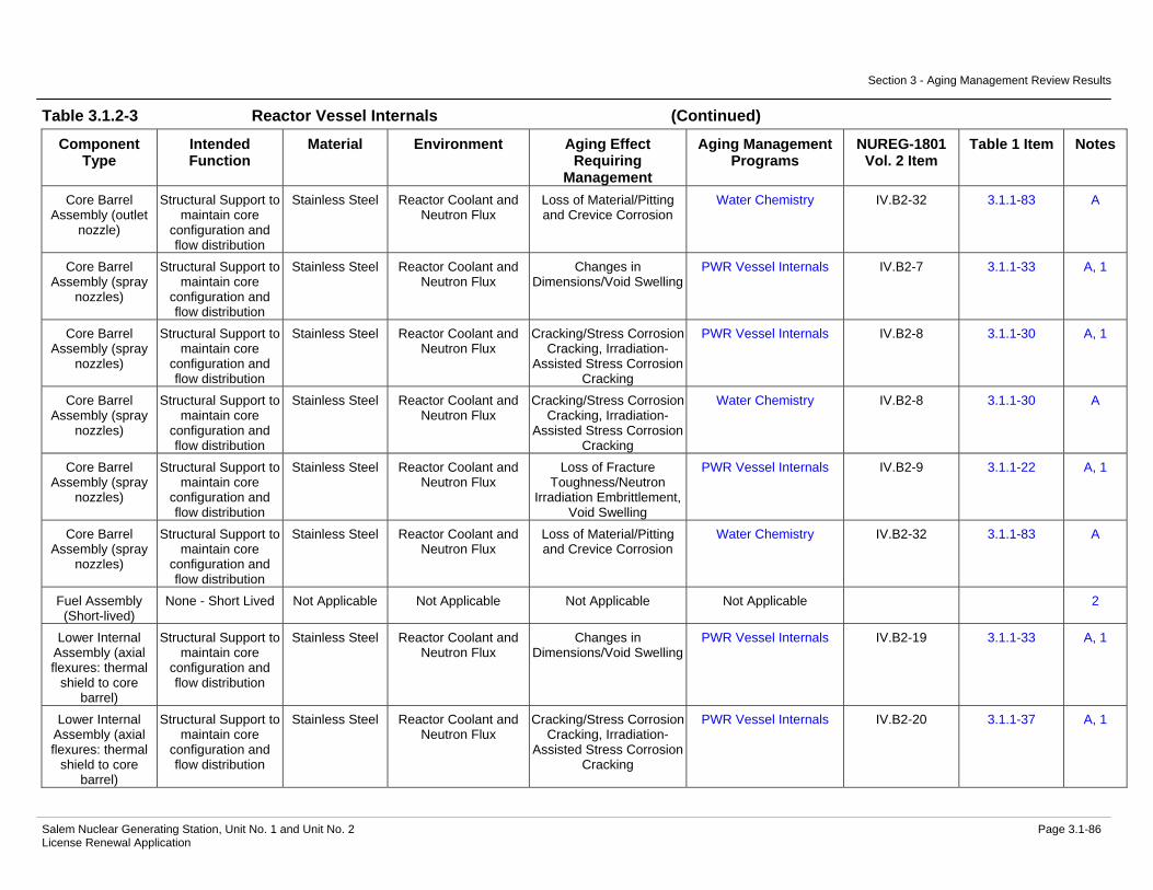
Section 3 - Aging Management Review Results
Salem Nuclear Generating Station, Unit No. 1 and Unit No. 2 Page 3.1-86 License Renewal Application
Table 3.1.2-3 Reactor Vessel Internals (Continued)
Component Type
Intended Function
Material Environment Aging Effect Requiring
Management
Aging Management Programs
NUREG-1801 Vol. 2 Item
Table 1 Item Notes
Core Barrel Assembly (outlet
nozzle)
Structural Support to maintain core
configuration and flow distribution
Stainless Steel Reactor Coolant and Neutron Flux
Loss of Material/Pitting and Crevice Corrosion
Water Chemistry IV.B2-32 3.1.1-83 A
Core Barrel Assembly (spray
nozzles)
Structural Support to maintain core
configuration and flow distribution
Stainless Steel Reactor Coolant and Neutron Flux
Changes in Dimensions/Void Swelling
PWR Vessel Internals IV.B2-7 3.1.1-33 A, 1
Core Barrel Assembly (spray
nozzles)
Structural Support to maintain core
configuration and flow distribution
Stainless Steel Reactor Coolant and Neutron Flux
Cracking/Stress Corrosion Cracking, Irradiation-
Assisted Stress Corrosion Cracking
PWR Vessel Internals IV.B2-8 3.1.1-30 A, 1
Core Barrel Assembly (spray
nozzles)
Structural Support to maintain core
configuration and flow distribution
Stainless Steel Reactor Coolant and Neutron Flux
Cracking/Stress Corrosion Cracking, Irradiation-
Assisted Stress Corrosion Cracking
Water Chemistry IV.B2-8 3.1.1-30 A
Core Barrel Assembly (spray
nozzles)
Structural Support to maintain core
configuration and flow distribution
Stainless Steel Reactor Coolant and Neutron Flux
Loss of Fracture Toughness/Neutron
Irradiation Embrittlement, Void Swelling
PWR Vessel Internals IV.B2-9 3.1.1-22 A, 1
Core Barrel Assembly (spray
nozzles)
Structural Support to maintain core
configuration and flow distribution
Stainless Steel Reactor Coolant and Neutron Flux
Loss of Material/Pitting and Crevice Corrosion
Water Chemistry IV.B2-32 3.1.1-83 A
Fuel Assembly (Short-lived)
None - Short Lived Not Applicable Not Applicable Not Applicable Not Applicable 2
Lower Internal Assembly (axial flexures: thermal
shield to core barrel)
Structural Support to maintain core
configuration and flow distribution
Stainless Steel Reactor Coolant and Neutron Flux
Changes in Dimensions/Void Swelling
PWR Vessel Internals IV.B2-19 3.1.1-33 A, 1
Lower Internal Assembly (axial flexures: thermal
shield to core barrel)
Structural Support to maintain core
configuration and flow distribution
Stainless Steel Reactor Coolant and Neutron Flux
Cracking/Stress Corrosion Cracking, Irradiation-
Assisted Stress Corrosion Cracking
PWR Vessel Internals IV.B2-20 3.1.1-37 A, 1
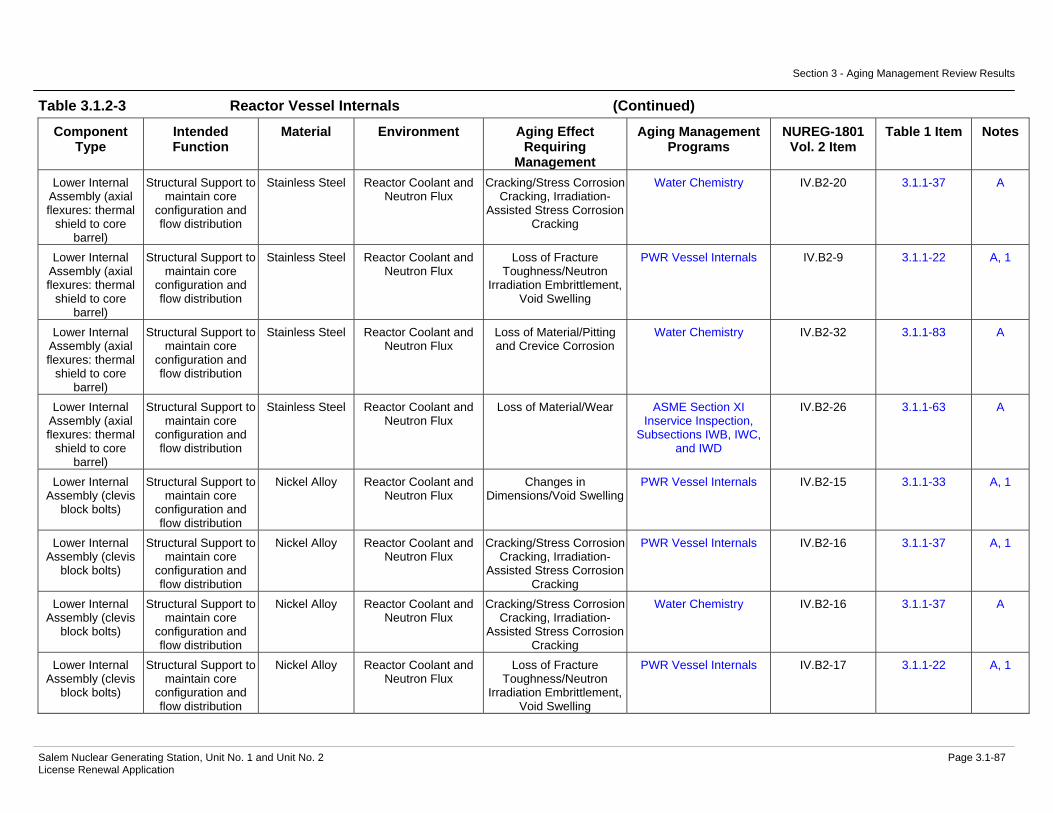
Section 3 - Aging Management Review Results
Salem Nuclear Generating Station, Unit No. 1 and Unit No. 2 Page 3.1-87 License Renewal Application
Table 3.1.2-3 Reactor Vessel Internals (Continued)
Component Type
Intended Function
Material Environment Aging Effect Requiring
Management
Aging Management Programs
NUREG-1801 Vol. 2 Item
Table 1 Item Notes
Lower Internal Assembly (axial flexures: thermal
shield to core barrel)
Structural Support to maintain core
configuration and flow distribution
Stainless Steel Reactor Coolant and Neutron Flux
Cracking/Stress Corrosion Cracking, Irradiation-
Assisted Stress Corrosion Cracking
Water Chemistry IV.B2-20 3.1.1-37 A
Lower Internal Assembly (axial flexures: thermal
shield to core barrel)
Structural Support to maintain core
configuration and flow distribution
Stainless Steel Reactor Coolant and Neutron Flux
Loss of Fracture Toughness/Neutron
Irradiation Embrittlement, Void Swelling
PWR Vessel Internals IV.B2-9 3.1.1-22 A, 1
Lower Internal Assembly (axial flexures: thermal
shield to core barrel)
Structural Support to maintain core
configuration and flow distribution
Stainless Steel Reactor Coolant and Neutron Flux
Loss of Material/Pitting and Crevice Corrosion
Water Chemistry IV.B2-32 3.1.1-83 A
Lower Internal Assembly (axial flexures: thermal
shield to core barrel)
Structural Support to maintain core
configuration and flow distribution
Stainless Steel Reactor Coolant and Neutron Flux
Loss of Material/Wear ASME Section XI Inservice Inspection,
Subsections IWB, IWC, and IWD
IV.B2-26 3.1.1-63 A
Lower Internal Assembly (clevis
block bolts)
Structural Support to maintain core
configuration and flow distribution
Nickel Alloy Reactor Coolant and Neutron Flux
Changes in Dimensions/Void Swelling
PWR Vessel Internals IV.B2-15 3.1.1-33 A, 1
Lower Internal Assembly (clevis
block bolts)
Structural Support to maintain core
configuration and flow distribution
Nickel Alloy Reactor Coolant and Neutron Flux
Cracking/Stress Corrosion Cracking, Irradiation-
Assisted Stress Corrosion Cracking
PWR Vessel Internals IV.B2-16 3.1.1-37 A, 1
Lower Internal Assembly (clevis
block bolts)
Structural Support to maintain core
configuration and flow distribution
Nickel Alloy Reactor Coolant and Neutron Flux
Cracking/Stress Corrosion Cracking, Irradiation-
Assisted Stress Corrosion Cracking
Water Chemistry IV.B2-16 3.1.1-37 A
Lower Internal Assembly (clevis
block bolts)
Structural Support to maintain core
configuration and flow distribution
Nickel Alloy Reactor Coolant and Neutron Flux
Loss of Fracture Toughness/Neutron
Irradiation Embrittlement, Void Swelling
PWR Vessel Internals IV.B2-17 3.1.1-22 A, 1

Section 3 - Aging Management Review Results
Salem Nuclear Generating Station, Unit No. 1 and Unit No. 2 Page 3.1-88 License Renewal Application
Table 3.1.2-3 Reactor Vessel Internals (Continued)
Component Type
Intended Function
Material Environment Aging Effect Requiring
Management
Aging Management Programs
NUREG-1801 Vol. 2 Item
Table 1 Item Notes
Lower Internal Assembly (clevis
block bolts)
Structural Support to maintain core
configuration and flow distribution
Nickel Alloy Reactor Coolant and Neutron Flux
Loss of Material/Pitting and Crevice Corrosion
Water Chemistry IV.B2-32 3.1.1-83 A
Lower Internal Assembly (clevis
block bolts)
Structural Support to maintain core
configuration and flow distribution
Nickel Alloy Reactor Coolant and Neutron Flux
Loss of Preload/Stress Relaxation
PWR Vessel Internals IV.B2-14 3.1.1-27 A, 1
Lower Internal Assembly (clevis block lock keys)
Structural Support to maintain core
configuration and flow distribution
Nickel Alloy Reactor Coolant and Neutron Flux
Changes in Dimensions/Void Swelling
PWR Vessel Internals IV.B2-19 3.1.1-33 A, 1
Lower Internal Assembly (clevis block lock keys)
Structural Support to maintain core
configuration and flow distribution
Nickel Alloy Reactor Coolant and Neutron Flux
Cracking/Stress Corrosion Cracking, Irradiation-
Assisted Stress Corrosion Cracking
PWR Vessel Internals IV.B2-20 3.1.1-37 A, 1
Lower Internal Assembly (clevis block lock keys)
Structural Support to maintain core
configuration and flow distribution
Nickel Alloy Reactor Coolant and Neutron Flux
Cracking/Stress Corrosion Cracking, Irradiation-
Assisted Stress Corrosion Cracking
Water Chemistry IV.B2-20 3.1.1-37 A
Lower Internal Assembly (clevis block lock keys)
Structural Support to maintain core
configuration and flow distribution
Nickel Alloy Reactor Coolant and Neutron Flux
Loss of Material/Pitting and Crevice Corrosion
Water Chemistry IV.B2-32 3.1.1-83 A
Lower Internal Assembly (clevis block lock keys)
Structural Support to maintain core
configuration and flow distribution
Nickel Alloy Reactor Coolant and Neutron Flux
Loss of Material/Wear ASME Section XI Inservice Inspection,
Subsections IWB, IWC, and IWD
H, 3
Lower Internal Assembly (clevis
blocks and inserts)
Structural Support to maintain core
configuration and flow distribution
Nickel Alloy Reactor Coolant and Neutron Flux
Changes in Dimensions/Void Swelling
PWR Vessel Internals IV.B2-19 3.1.1-33 A, 1
Lower Internal Assembly (clevis
blocks and inserts)
Structural Support to maintain core
configuration and flow distribution
Nickel Alloy Reactor Coolant and Neutron Flux
Cracking/Stress Corrosion Cracking, Irradiation-
Assisted Stress Corrosion Cracking
PWR Vessel Internals IV.B2-20 3.1.1-37 A, 1
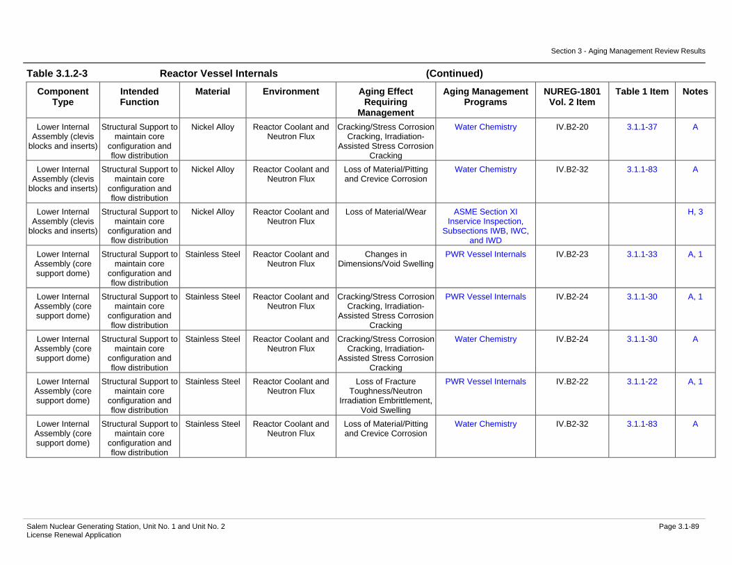
Section 3 - Aging Management Review Results
Salem Nuclear Generating Station, Unit No. 1 and Unit No. 2 Page 3.1-89 License Renewal Application
Table 3.1.2-3 Reactor Vessel Internals (Continued)
Component Type
Intended Function
Material Environment Aging Effect Requiring
Management
Aging Management Programs
NUREG-1801 Vol. 2 Item
Table 1 Item Notes
Lower Internal Assembly (clevis
blocks and inserts)
Structural Support to maintain core
configuration and flow distribution
Nickel Alloy Reactor Coolant and Neutron Flux
Cracking/Stress Corrosion Cracking, Irradiation-
Assisted Stress Corrosion Cracking
Water Chemistry IV.B2-20 3.1.1-37 A
Lower Internal Assembly (clevis
blocks and inserts)
Structural Support to maintain core
configuration and flow distribution
Nickel Alloy Reactor Coolant and Neutron Flux
Loss of Material/Pitting and Crevice Corrosion
Water Chemistry IV.B2-32 3.1.1-83 A
Lower Internal Assembly (clevis
blocks and inserts)
Structural Support to maintain core
configuration and flow distribution
Nickel Alloy Reactor Coolant and Neutron Flux
Loss of Material/Wear ASME Section XI Inservice Inspection,
Subsections IWB, IWC, and IWD
H, 3
Lower Internal Assembly (core support dome)
Structural Support to maintain core
configuration and flow distribution
Stainless Steel Reactor Coolant and Neutron Flux
Changes in Dimensions/Void Swelling
PWR Vessel Internals IV.B2-23 3.1.1-33 A, 1
Lower Internal Assembly (core support dome)
Structural Support to maintain core
configuration and flow distribution
Stainless Steel Reactor Coolant and Neutron Flux
Cracking/Stress Corrosion Cracking, Irradiation-
Assisted Stress Corrosion Cracking
PWR Vessel Internals IV.B2-24 3.1.1-30 A, 1
Lower Internal Assembly (core support dome)
Structural Support to maintain core
configuration and flow distribution
Stainless Steel Reactor Coolant and Neutron Flux
Cracking/Stress Corrosion Cracking, Irradiation-
Assisted Stress Corrosion Cracking
Water Chemistry IV.B2-24 3.1.1-30 A
Lower Internal Assembly (core support dome)
Structural Support to maintain core
configuration and flow distribution
Stainless Steel Reactor Coolant and Neutron Flux
Loss of Fracture Toughness/Neutron
Irradiation Embrittlement, Void Swelling
PWR Vessel Internals IV.B2-22 3.1.1-22 A, 1
Lower Internal Assembly (core support dome)
Structural Support to maintain core
configuration and flow distribution
Stainless Steel Reactor Coolant and Neutron Flux
Loss of Material/Pitting and Crevice Corrosion
Water Chemistry IV.B2-32 3.1.1-83 A

Section 3 - Aging Management Review Results
Salem Nuclear Generating Station, Unit No. 1 and Unit No. 2 Page 3.1-90 License Renewal Application
Table 3.1.2-3 Reactor Vessel Internals (Continued)
Component Type
Intended Function
Material Environment Aging Effect Requiring
Management
Aging Management Programs
NUREG-1801 Vol. 2 Item
Table 1 Item Notes
Lower Internal Assembly (core
support, incl'g core support lugs, columns and
sleeves)
Structural Support to maintain core
configuration and flow distribution
Nickel Alloy Reactor Coolant and Neutron Flux
Changes in Dimensions/Void Swelling
PWR Vessel Internals IV.B2-19 3.1.1-33 A, 1
Lower Internal Assembly (core
support, incl'g core support lugs, columns and
sleeves)
Structural Support to maintain core
configuration and flow distribution
Nickel Alloy Reactor Coolant and Neutron Flux
Cracking/Stress Corrosion Cracking, Irradiation-
Assisted Stress Corrosion Cracking
PWR Vessel Internals IV.B2-20 3.1.1-37 A, 1
Lower Internal Assembly (core
support, incl'g core support lugs, columns and
sleeves)
Structural Support to maintain core
configuration and flow distribution
Nickel Alloy Reactor Coolant and Neutron Flux
Cracking/Stress Corrosion Cracking, Irradiation-
Assisted Stress Corrosion Cracking
Water Chemistry IV.B2-20 3.1.1-37 A
Lower Internal Assembly (core
support, incl'g core support lugs, columns and
sleeves)
Structural Support to maintain core
configuration and flow distribution
Nickel Alloy Reactor Coolant and Neutron Flux
Cumulative Fatigue Damage/Fatigue
TLAA IV.B2-31 3.1.1-5 A, 6
Lower Internal Assembly (core
support, incl'g core support lugs, columns and
sleeves)
Structural Support to maintain core
configuration and flow distribution
Nickel Alloy Reactor Coolant and Neutron Flux
Loss of Material/Pitting and Crevice Corrosion
Water Chemistry IV.B2-32 3.1.1-83 A
Lower Internal Assembly (core
support, incl'g core support lugs, columns and
sleeves)
Structural Support to maintain core
configuration and flow distribution
Stainless Steel Reactor Coolant and Neutron Flux
Changes in Dimensions/Void Swelling
PWR Vessel Internals IV.B2-23 3.1.1-33 A, 1
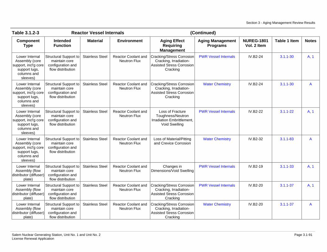
Section 3 - Aging Management Review Results
Salem Nuclear Generating Station, Unit No. 1 and Unit No. 2 Page 3.1-91 License Renewal Application
Table 3.1.2-3 Reactor Vessel Internals (Continued)
Component Type
Intended Function
Material Environment Aging Effect Requiring
Management
Aging Management Programs
NUREG-1801 Vol. 2 Item
Table 1 Item Notes
Lower Internal Assembly (core
support, incl'g core support lugs, columns and
sleeves)
Structural Support to maintain core
configuration and flow distribution
Stainless Steel Reactor Coolant and Neutron Flux
Cracking/Stress Corrosion Cracking, Irradiation-
Assisted Stress Corrosion Cracking
PWR Vessel Internals IV.B2-24 3.1.1-30 A, 1
Lower Internal Assembly (core
support, incl'g core support lugs, columns and
sleeves)
Structural Support to maintain core
configuration and flow distribution
Stainless Steel Reactor Coolant and Neutron Flux
Cracking/Stress Corrosion Cracking, Irradiation-
Assisted Stress Corrosion Cracking
Water Chemistry IV.B2-24 3.1.1-30 A
Lower Internal Assembly (core
support, incl'g core support lugs, columns and
sleeves)
Structural Support to maintain core
configuration and flow distribution
Stainless Steel Reactor Coolant and Neutron Flux
Loss of Fracture Toughness/Neutron
Irradiation Embrittlement, Void Swelling
PWR Vessel Internals IV.B2-22 3.1.1-22 A, 1
Lower Internal Assembly (core
support, incl'g core support lugs, columns and
sleeves)
Structural Support to maintain core
configuration and flow distribution
Stainless Steel Reactor Coolant and Neutron Flux
Loss of Material/Pitting and Crevice Corrosion
Water Chemistry IV.B2-32 3.1.1-83 A
Lower Internal Assembly (flow
distributor (diffuser) plate)
Structural Support to maintain core
configuration and flow distribution
Stainless Steel Reactor Coolant and Neutron Flux
Changes in Dimensions/Void Swelling
PWR Vessel Internals IV.B2-19 3.1.1-33 A, 1
Lower Internal Assembly (flow
distributor (diffuser) plate)
Structural Support to maintain core
configuration and flow distribution
Stainless Steel Reactor Coolant and Neutron Flux
Cracking/Stress Corrosion Cracking, Irradiation-
Assisted Stress Corrosion Cracking
PWR Vessel Internals IV.B2-20 3.1.1-37 A, 1
Lower Internal Assembly (flow
distributor (diffuser) plate)
Structural Support to maintain core
configuration and flow distribution
Stainless Steel Reactor Coolant and Neutron Flux
Cracking/Stress Corrosion Cracking, Irradiation-
Assisted Stress Corrosion Cracking
Water Chemistry IV.B2-20 3.1.1-37 A

Section 3 - Aging Management Review Results
Salem Nuclear Generating Station, Unit No. 1 and Unit No. 2 Page 3.1-92 License Renewal Application
Table 3.1.2-3 Reactor Vessel Internals (Continued)
Component Type
Intended Function
Material Environment Aging Effect Requiring
Management
Aging Management Programs
NUREG-1801 Vol. 2 Item
Table 1 Item Notes
Lower Internal Assembly (flow
distributor (diffuser) plate)
Structural Support to maintain core
configuration and flow distribution
Stainless Steel Reactor Coolant and Neutron Flux
Loss of Fracture Toughness/Neutron
Irradiation Embrittlement, Void Swelling
PWR Vessel Internals IV.B2-18 3.1.1-22 A, 1
Lower Internal Assembly (flow
distributor (diffuser) plate)
Structural Support to maintain core
configuration and flow distribution
Stainless Steel Reactor Coolant and Neutron Flux
Loss of Material/Pitting and Crevice Corrosion
Water Chemistry IV.B2-32 3.1.1-83 A
Lower Internal Assembly (fuel
assembly locating pin bolts)
Structural Support to maintain core
configuration and flow distribution
Stainless Steel Bolting
Reactor Coolant and Neutron Flux
Changes in Dimensions/Void Swelling
PWR Vessel Internals IV.B2-15 3.1.1-33 A, 1
Lower Internal Assembly (fuel
assembly locating pin bolts)
Structural Support to maintain core
configuration and flow distribution
Stainless Steel Bolting
Reactor Coolant and Neutron Flux
Cracking/Stress Corrosion Cracking, Irradiation-
Assisted Stress Corrosion Cracking
PWR Vessel Internals IV.B2-16 3.1.1-37 A, 1
Lower Internal Assembly (fuel
assembly locating pin bolts)
Structural Support to maintain core
configuration and flow distribution
Stainless Steel Bolting
Reactor Coolant and Neutron Flux
Cracking/Stress Corrosion Cracking, Irradiation-
Assisted Stress Corrosion Cracking
Water Chemistry IV.B2-16 3.1.1-37 A
Lower Internal Assembly (fuel
assembly locating pin bolts)
Structural Support to maintain core
configuration and flow distribution
Stainless Steel Bolting
Reactor Coolant and Neutron Flux
Loss of Fracture Toughness/Neutron
Irradiation Embrittlement, Void Swelling
PWR Vessel Internals IV.B2-17 3.1.1-22 A, 1
Lower Internal Assembly (fuel
assembly locating pin bolts)
Structural Support to maintain core
configuration and flow distribution
Stainless Steel Bolting
Reactor Coolant and Neutron Flux
Loss of Material/Pitting and Crevice Corrosion
Water Chemistry IV.B2-32 3.1.1-83 A
Lower Internal Assembly (fuel
assembly locating pin bolts)
Structural Support to maintain core
configuration and flow distribution
Stainless Steel Bolting
Reactor Coolant and Neutron Flux
Loss of Preload/Stress Relaxation
PWR Vessel Internals IV.B2-14 3.1.1-27 A, 1
Lower Internal Assembly (fuel
assembly locating pins and lockcaps)
Structural Support to maintain core
configuration and flow distribution
Stainless Steel Reactor Coolant and Neutron Flux
Changes in Dimensions/Void Swelling
PWR Vessel Internals IV.B2-15 3.1.1-33 A, 1

Section 3 - Aging Management Review Results
Salem Nuclear Generating Station, Unit No. 1 and Unit No. 2 Page 3.1-93 License Renewal Application
Table 3.1.2-3 Reactor Vessel Internals (Continued)
Component Type
Intended Function
Material Environment Aging Effect Requiring
Management
Aging Management Programs
NUREG-1801 Vol. 2 Item
Table 1 Item Notes
Lower Internal Assembly (fuel
assembly locating pins and lockcaps)
Structural Support to maintain core
configuration and flow distribution
Stainless Steel Reactor Coolant and Neutron Flux
Cracking/Stress Corrosion Cracking, Irradiation-
Assisted Stress Corrosion Cracking
PWR Vessel Internals IV.B2-16 3.1.1-37 A, 1
Lower Internal Assembly (fuel
assembly locating pins and lockcaps)
Structural Support to maintain core
configuration and flow distribution
Stainless Steel Reactor Coolant and Neutron Flux
Cracking/Stress Corrosion Cracking, Irradiation-
Assisted Stress Corrosion Cracking
Water Chemistry IV.B2-16 3.1.1-37 A
Lower Internal Assembly (fuel
assembly locating pins and lockcaps)
Structural Support to maintain core
configuration and flow distribution
Stainless Steel Reactor Coolant and Neutron Flux
Loss of Fracture Toughness/Neutron
Irradiation Embrittlement, Void Swelling
PWR Vessel Internals IV.B2-17 3.1.1-22 A, 1
Lower Internal Assembly (fuel
assembly locating pins and lockcaps)
Structural Support to maintain core
configuration and flow distribution
Stainless Steel Reactor Coolant and Neutron Flux
Loss of Material/Pitting and Crevice Corrosion
Water Chemistry IV.B2-32 3.1.1-83 A
Lower Internal Assembly (inserts for clevis blocks,
incl'g lock bars and dowels)
Structural Support to maintain core
configuration and flow distribution
Nickel Alloy Reactor Coolant and Neutron Flux
Changes in Dimensions/Void Swelling
PWR Vessel Internals IV.B2-19 3.1.1-33 A, 1
Lower Internal Assembly (inserts for clevis blocks,
incl'g lock bars and dowels)
Structural Support to maintain core
configuration and flow distribution
Nickel Alloy Reactor Coolant and Neutron Flux
Cracking/Stress Corrosion Cracking, Irradiation-
Assisted Stress Corrosion Cracking
PWR Vessel Internals IV.B2-20 3.1.1-37 A, 1
Lower Internal Assembly (inserts for clevis blocks,
incl'g lock bars and dowels)
Structural Support to maintain core
configuration and flow distribution
Nickel Alloy Reactor Coolant and Neutron Flux
Cracking/Stress Corrosion Cracking, Irradiation-
Assisted Stress Corrosion Cracking
Water Chemistry IV.B2-20 3.1.1-37 A
Lower Internal Assembly (inserts for clevis blocks,
incl'g lock bars and dowels)
Structural Support to maintain core
configuration and flow distribution
Nickel Alloy Reactor Coolant and Neutron Flux
Loss of Material/Pitting and Crevice Corrosion
Water Chemistry IV.B2-32 3.1.1-83 A

Section 3 - Aging Management Review Results
Salem Nuclear Generating Station, Unit No. 1 and Unit No. 2 Page 3.1-94 License Renewal Application
Table 3.1.2-3 Reactor Vessel Internals (Continued)
Component Type
Intended Function
Material Environment Aging Effect Requiring
Management
Aging Management Programs
NUREG-1801 Vol. 2 Item
Table 1 Item Notes
Lower Internal Assembly (inserts for clevis blocks,
incl'g lock bars and dowels)
Structural Support to maintain core
configuration and flow distribution
Nickel Alloy Reactor Coolant and Neutron Flux
Loss of Material/Wear ASME Section XI Inservice Inspection,
Subsections IWB, IWC, and IWD
H, 3
Lower Internal Assembly
(irradiation sample access plugs)
Structural Support to maintain core
configuration and flow distribution
Stainless Steel Reactor Coolant and Neutron Flux
Changes in Dimensions/Void Swelling
PWR Vessel Internals IV.B2-15 3.1.1-33 A, 1
Lower Internal Assembly
(irradiation sample access plugs)
Structural Support to maintain core
configuration and flow distribution
Stainless Steel Reactor Coolant and Neutron Flux
Cracking/Stress Corrosion Cracking, Irradiation-
Assisted Stress Corrosion Cracking
PWR Vessel Internals IV.B2-16 3.1.1-37 A, 1
Lower Internal Assembly
(irradiation sample access plugs)
Structural Support to maintain core
configuration and flow distribution
Stainless Steel Reactor Coolant and Neutron Flux
Cracking/Stress Corrosion Cracking, Irradiation-
Assisted Stress Corrosion Cracking
Water Chemistry IV.B2-16 3.1.1-37 A
Lower Internal Assembly
(irradiation sample access plugs)
Structural Support to maintain core
configuration and flow distribution
Stainless Steel Reactor Coolant and Neutron Flux
Loss of Fracture Toughness/Neutron
Irradiation Embrittlement, Void Swelling
PWR Vessel Internals IV.B2-17 3.1.1-22 A, 1
Lower Internal Assembly
(irradiation sample access plugs)
Structural Support to maintain core
configuration and flow distribution
Stainless Steel Reactor Coolant and Neutron Flux
Loss of Material/Pitting and Crevice Corrosion
Water Chemistry IV.B2-32 3.1.1-83 A
Lower Internal Assembly
(irradiation sample access plugs)
Structural Support to maintain core
configuration and flow distribution
Stainless Steel Reactor Coolant and Neutron Flux
Loss of Preload/Stress Relaxation
PWR Vessel Internals IV.B2-14 3.1.1-27 A, 1
Lower Internal Assembly
(irradiation sample guide bolts)
Structural Support to maintain core
configuration and flow distribution
Stainless Steel Bolting
Reactor Coolant and Neutron Flux
Changes in Dimensions/Void Swelling
PWR Vessel Internals IV.B2-15 3.1.1-33 A, 1
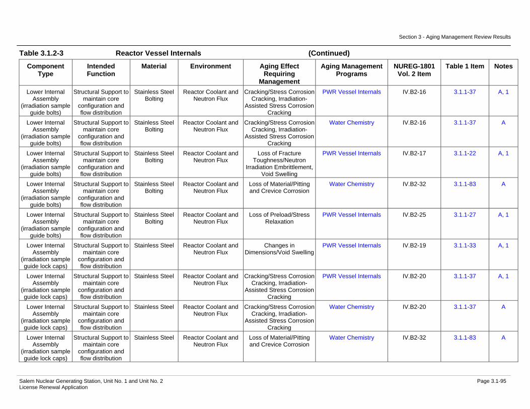
Section 3 - Aging Management Review Results
Salem Nuclear Generating Station, Unit No. 1 and Unit No. 2 Page 3.1-95 License Renewal Application
Table 3.1.2-3 Reactor Vessel Internals (Continued)
Component Type
Intended Function
Material Environment Aging Effect Requiring
Management
Aging Management Programs
NUREG-1801 Vol. 2 Item
Table 1 Item Notes
Lower Internal Assembly
(irradiation sample guide bolts)
Structural Support to maintain core
configuration and flow distribution
Stainless Steel Bolting
Reactor Coolant and Neutron Flux
Cracking/Stress Corrosion Cracking, Irradiation-
Assisted Stress Corrosion Cracking
PWR Vessel Internals IV.B2-16 3.1.1-37 A, 1
Lower Internal Assembly
(irradiation sample guide bolts)
Structural Support to maintain core
configuration and flow distribution
Stainless Steel Bolting
Reactor Coolant and Neutron Flux
Cracking/Stress Corrosion Cracking, Irradiation-
Assisted Stress Corrosion Cracking
Water Chemistry IV.B2-16 3.1.1-37 A
Lower Internal Assembly
(irradiation sample guide bolts)
Structural Support to maintain core
configuration and flow distribution
Stainless Steel Bolting
Reactor Coolant and Neutron Flux
Loss of Fracture Toughness/Neutron
Irradiation Embrittlement, Void Swelling
PWR Vessel Internals IV.B2-17 3.1.1-22 A, 1
Lower Internal Assembly
(irradiation sample guide bolts)
Structural Support to maintain core
configuration and flow distribution
Stainless Steel Bolting
Reactor Coolant and Neutron Flux
Loss of Material/Pitting and Crevice Corrosion
Water Chemistry IV.B2-32 3.1.1-83 A
Lower Internal Assembly
(irradiation sample guide bolts)
Structural Support to maintain core
configuration and flow distribution
Stainless Steel Bolting
Reactor Coolant and Neutron Flux
Loss of Preload/Stress Relaxation
PWR Vessel Internals IV.B2-25 3.1.1-27 A, 1
Lower Internal Assembly
(irradiation sample guide lock caps)
Structural Support to maintain core
configuration and flow distribution
Stainless Steel Reactor Coolant and Neutron Flux
Changes in Dimensions/Void Swelling
PWR Vessel Internals IV.B2-19 3.1.1-33 A, 1
Lower Internal Assembly
(irradiation sample guide lock caps)
Structural Support to maintain core
configuration and flow distribution
Stainless Steel Reactor Coolant and Neutron Flux
Cracking/Stress Corrosion Cracking, Irradiation-
Assisted Stress Corrosion Cracking
PWR Vessel Internals IV.B2-20 3.1.1-37 A, 1
Lower Internal Assembly
(irradiation sample guide lock caps)
Structural Support to maintain core
configuration and flow distribution
Stainless Steel Reactor Coolant and Neutron Flux
Cracking/Stress Corrosion Cracking, Irradiation-
Assisted Stress Corrosion Cracking
Water Chemistry IV.B2-20 3.1.1-37 A
Lower Internal Assembly
(irradiation sample guide lock caps)
Structural Support to maintain core
configuration and flow distribution
Stainless Steel Reactor Coolant and Neutron Flux
Loss of Material/Pitting and Crevice Corrosion
Water Chemistry IV.B2-32 3.1.1-83 A

Section 3 - Aging Management Review Results
Salem Nuclear Generating Station, Unit No. 1 and Unit No. 2 Page 3.1-96 License Renewal Application
Table 3.1.2-3 Reactor Vessel Internals (Continued)
Component Type
Intended Function
Material Environment Aging Effect Requiring
Management
Aging Management Programs
NUREG-1801 Vol. 2 Item
Table 1 Item Notes
Lower Internal Assembly
(irradiation sample guide lock caps)
Structural Support to maintain core
configuration and flow distribution
Stainless Steel Reactor Coolant and Neutron Flux
Loss of Material/Wear ASME Section XI Inservice Inspection,
Subsections IWB, IWC, and IWD
IV.B2-26 3.1.1-63 A
Lower Internal Assembly
(irradiation sample guide)
None - Short Lived Not Applicable Not Applicable Not Applicable Not Applicable 4
Lower Internal Assembly (lower
core plate)
Structural Support to maintain core
configuration and flow distribution
Stainless Steel Reactor Coolant and Neutron Flux
Changes in Dimensions/Void Swelling
PWR Vessel Internals IV.B2-19 3.1.1-33 A, 1
Lower Internal Assembly (lower
core plate)
Structural Support to maintain core
configuration and flow distribution
Stainless Steel Reactor Coolant and Neutron Flux
Cracking/Stress Corrosion Cracking, Irradiation-
Assisted Stress Corrosion Cracking
PWR Vessel Internals IV.B2-20 3.1.1-37 A, 1
Lower Internal Assembly (lower
core plate)
Structural Support to maintain core
configuration and flow distribution
Stainless Steel Reactor Coolant and Neutron Flux
Cracking/Stress Corrosion Cracking, Irradiation-
Assisted Stress Corrosion Cracking
Water Chemistry IV.B2-20 3.1.1-37 A
Lower Internal Assembly (lower
core plate)
Structural Support to maintain core
configuration and flow distribution
Stainless Steel Reactor Coolant and Neutron Flux
Cumulative Fatigue Damage/Fatigue
TLAA IV.B2-31 3.1.1-5 A, 6
Lower Internal Assembly (lower
core plate)
Structural Support to maintain core
configuration and flow distribution
Stainless Steel Reactor Coolant and Neutron Flux
Loss of Fracture Toughness/Neutron
Irradiation Embrittlement, Void Swelling
PWR Vessel Internals IV.B2-18 3.1.1-22 A, 1
Lower Internal Assembly (lower
core plate)
Structural Support to maintain core
configuration and flow distribution
Stainless Steel Reactor Coolant and Neutron Flux
Loss of Material/Pitting and Crevice Corrosion
Water Chemistry IV.B2-32 3.1.1-83 A
Lower Internal Assembly (lower
core support energy absorbers)
Structural Support to maintain core
configuration and flow distribution
Stainless Steel Reactor Coolant and Neutron Flux
Changes in Dimensions/Void Swelling
PWR Vessel Internals IV.B2-23 3.1.1-33 A, 1

Section 3 - Aging Management Review Results
Salem Nuclear Generating Station, Unit No. 1 and Unit No. 2 Page 3.1-97 License Renewal Application
Table 3.1.2-3 Reactor Vessel Internals (Continued)
Component Type
Intended Function
Material Environment Aging Effect Requiring
Management
Aging Management Programs
NUREG-1801 Vol. 2 Item
Table 1 Item Notes
Lower Internal Assembly (lower
core support energy absorbers)
Structural Support to maintain core
configuration and flow distribution
Stainless Steel Reactor Coolant and Neutron Flux
Cracking/Stress Corrosion Cracking, Irradiation-
Assisted Stress Corrosion Cracking
PWR Vessel Internals IV.B2-24 3.1.1-30 A, 1
Lower Internal Assembly (lower
core support energy absorbers)
Structural Support to maintain core
configuration and flow distribution
Stainless Steel Reactor Coolant and Neutron Flux
Cracking/Stress Corrosion Cracking, Irradiation-
Assisted Stress Corrosion Cracking
Water Chemistry IV.B2-24 3.1.1-30 A
Lower Internal Assembly (lower
core support energy absorbers)
Structural Support to maintain core
configuration and flow distribution
Stainless Steel Reactor Coolant and Neutron Flux
Loss of Fracture Toughness/Neutron
Irradiation Embrittlement, Void Swelling
PWR Vessel Internals IV.B2-22 3.1.1-22 A, 1
Lower Internal Assembly (lower
core support energy absorbers)
Structural Support to maintain core
configuration and flow distribution
Stainless Steel Reactor Coolant and Neutron Flux
Loss of Material/Pitting and Crevice Corrosion
Water Chemistry IV.B2-32 3.1.1-83 A
Lower Internal Assembly (lower
core support guide post and housing)
Structural Support to maintain core
configuration and flow distribution
Stainless Steel Reactor Coolant and Neutron Flux
Changes in Dimensions/Void Swelling
PWR Vessel Internals IV.B2-23 3.1.1-33 A, 1
Lower Internal Assembly (lower
core support guide post and housing)
Structural Support to maintain core
configuration and flow distribution
Stainless Steel Reactor Coolant and Neutron Flux
Cracking/Stress Corrosion Cracking, Irradiation-
Assisted Stress Corrosion Cracking
PWR Vessel Internals IV.B2-24 3.1.1-30 A, 1
Lower Internal Assembly (lower
core support guide post and housing)
Structural Support to maintain core
configuration and flow distribution
Stainless Steel Reactor Coolant and Neutron Flux
Cracking/Stress Corrosion Cracking, Irradiation-
Assisted Stress Corrosion Cracking
Water Chemistry IV.B2-24 3.1.1-30 A
Lower Internal Assembly (lower
core support guide post and housing)
Structural Support to maintain core
configuration and flow distribution
Stainless Steel Reactor Coolant and Neutron Flux
Loss of Fracture Toughness/Neutron
Irradiation Embrittlement, Void Swelling
PWR Vessel Internals IV.B2-22 3.1.1-22 A, 1
Lower Internal Assembly (lower
core support guide post and housing)
Structural Support to maintain core
configuration and flow distribution
Stainless Steel Reactor Coolant and Neutron Flux
Loss of Material/Pitting and Crevice Corrosion
Water Chemistry IV.B2-32 3.1.1-83 A

Section 3 - Aging Management Review Results
Salem Nuclear Generating Station, Unit No. 1 and Unit No. 2 Page 3.1-98 License Renewal Application
Table 3.1.2-3 Reactor Vessel Internals (Continued)
Component Type
Intended Function
Material Environment Aging Effect Requiring
Management
Aging Management Programs
NUREG-1801 Vol. 2 Item
Table 1 Item Notes
Lower Internal Assembly (lower core support ring)
Structural Support to maintain core
configuration and flow distribution
Stainless Steel Reactor Coolant and Neutron Flux
Changes in Dimensions/Void Swelling
PWR Vessel Internals IV.B2-23 3.1.1-33 A, 1
Lower Internal Assembly (lower core support ring)
Structural Support to maintain core
configuration and flow distribution
Stainless Steel Reactor Coolant and Neutron Flux
Cracking/Stress Corrosion Cracking, Irradiation-
Assisted Stress Corrosion Cracking
PWR Vessel Internals IV.B2-24 3.1.1-30 A, 1
Lower Internal Assembly (lower core support ring)
Structural Support to maintain core
configuration and flow distribution
Stainless Steel Reactor Coolant and Neutron Flux
Cracking/Stress Corrosion Cracking, Irradiation-
Assisted Stress Corrosion Cracking
Water Chemistry IV.B2-24 3.1.1-30 A
Lower Internal Assembly (lower core support ring)
Structural Support to maintain core
configuration and flow distribution
Stainless Steel Reactor Coolant and Neutron Flux
Loss of Fracture Toughness/Neutron
Irradiation Embrittlement, Void Swelling
PWR Vessel Internals IV.B2-22 3.1.1-22 A, 1
Lower Internal Assembly (lower core support ring)
Structural Support to maintain core
configuration and flow distribution
Stainless Steel Reactor Coolant and Neutron Flux
Loss of Material/Pitting and Crevice Corrosion
Water Chemistry IV.B2-32 3.1.1-83 A
Lower Internal Assembly (lower
radial support keys)
Structural Support to maintain core
configuration and flow distribution
Stainless Steel Reactor Coolant and Neutron Flux
Changes in Dimensions/Void Swelling
PWR Vessel Internals IV.B2-19 3.1.1-33 A, 1
Lower Internal Assembly (lower
radial support keys)
Structural Support to maintain core
configuration and flow distribution
Stainless Steel Reactor Coolant and Neutron Flux
Cracking/Stress Corrosion Cracking, Irradiation-
Assisted Stress Corrosion Cracking
PWR Vessel Internals IV.B2-20 3.1.1-37 A, 1
Lower Internal Assembly (lower
radial support keys)
Structural Support to maintain core
configuration and flow distribution
Stainless Steel Reactor Coolant and Neutron Flux
Cracking/Stress Corrosion Cracking, Irradiation-
Assisted Stress Corrosion Cracking
Water Chemistry IV.B2-20 3.1.1-37 A
Lower Internal Assembly (lower
radial support keys)
Structural Support to maintain core
configuration and flow distribution
Stainless Steel Reactor Coolant and Neutron Flux
Loss of Material/Pitting and Crevice Corrosion
Water Chemistry IV.B2-32 3.1.1-83 A
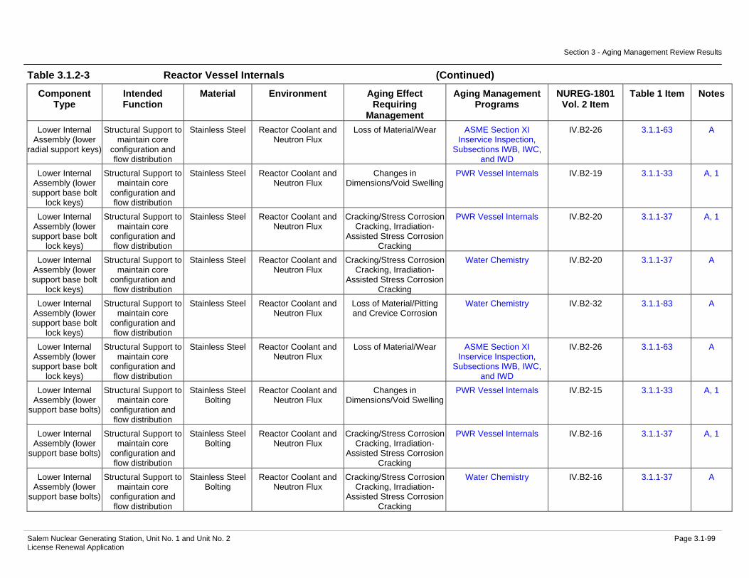
Section 3 - Aging Management Review Results
Salem Nuclear Generating Station, Unit No. 1 and Unit No. 2 Page 3.1-99 License Renewal Application
Table 3.1.2-3 Reactor Vessel Internals (Continued)
Component Type
Intended Function
Material Environment Aging Effect Requiring
Management
Aging Management Programs
NUREG-1801 Vol. 2 Item
Table 1 Item Notes
Lower Internal Assembly (lower
radial support keys)
Structural Support to maintain core
configuration and flow distribution
Stainless Steel Reactor Coolant and Neutron Flux
Loss of Material/Wear ASME Section XI Inservice Inspection,
Subsections IWB, IWC, and IWD
IV.B2-26 3.1.1-63 A
Lower Internal Assembly (lower support base bolt
lock keys)
Structural Support to maintain core
configuration and flow distribution
Stainless Steel Reactor Coolant and Neutron Flux
Changes in Dimensions/Void Swelling
PWR Vessel Internals IV.B2-19 3.1.1-33 A, 1
Lower Internal Assembly (lower support base bolt
lock keys)
Structural Support to maintain core
configuration and flow distribution
Stainless Steel Reactor Coolant and Neutron Flux
Cracking/Stress Corrosion Cracking, Irradiation-
Assisted Stress Corrosion Cracking
PWR Vessel Internals IV.B2-20 3.1.1-37 A, 1
Lower Internal Assembly (lower support base bolt
lock keys)
Structural Support to maintain core
configuration and flow distribution
Stainless Steel Reactor Coolant and Neutron Flux
Cracking/Stress Corrosion Cracking, Irradiation-
Assisted Stress Corrosion Cracking
Water Chemistry IV.B2-20 3.1.1-37 A
Lower Internal Assembly (lower support base bolt
lock keys)
Structural Support to maintain core
configuration and flow distribution
Stainless Steel Reactor Coolant and Neutron Flux
Loss of Material/Pitting and Crevice Corrosion
Water Chemistry IV.B2-32 3.1.1-83 A
Lower Internal Assembly (lower support base bolt
lock keys)
Structural Support to maintain core
configuration and flow distribution
Stainless Steel Reactor Coolant and Neutron Flux
Loss of Material/Wear ASME Section XI Inservice Inspection,
Subsections IWB, IWC, and IWD
IV.B2-26 3.1.1-63 A
Lower Internal Assembly (lower
support base bolts)
Structural Support to maintain core
configuration and flow distribution
Stainless Steel Bolting
Reactor Coolant and Neutron Flux
Changes in Dimensions/Void Swelling
PWR Vessel Internals IV.B2-15 3.1.1-33 A, 1
Lower Internal Assembly (lower
support base bolts)
Structural Support to maintain core
configuration and flow distribution
Stainless Steel Bolting
Reactor Coolant and Neutron Flux
Cracking/Stress Corrosion Cracking, Irradiation-
Assisted Stress Corrosion Cracking
PWR Vessel Internals IV.B2-16 3.1.1-37 A, 1
Lower Internal Assembly (lower
support base bolts)
Structural Support to maintain core
configuration and flow distribution
Stainless Steel Bolting
Reactor Coolant and Neutron Flux
Cracking/Stress Corrosion Cracking, Irradiation-
Assisted Stress Corrosion Cracking
Water Chemistry IV.B2-16 3.1.1-37 A

Section 3 - Aging Management Review Results
Salem Nuclear Generating Station, Unit No. 1 and Unit No. 2 Page 3.1-100 License Renewal Application
Table 3.1.2-3 Reactor Vessel Internals (Continued)
Component Type
Intended Function
Material Environment Aging Effect Requiring
Management
Aging Management Programs
NUREG-1801 Vol. 2 Item
Table 1 Item Notes
Lower Internal Assembly (lower
support base bolts)
Structural Support to maintain core
configuration and flow distribution
Stainless Steel Bolting
Reactor Coolant and Neutron Flux
Loss of Fracture Toughness/Neutron
Irradiation Embrittlement, Void Swelling
PWR Vessel Internals IV.B2-17 3.1.1-22 A, 1
Lower Internal Assembly (lower
support base bolts)
Structural Support to maintain core
configuration and flow distribution
Stainless Steel Bolting
Reactor Coolant and Neutron Flux
Loss of Material/Pitting and Crevice Corrosion
Water Chemistry IV.B2-32 3.1.1-83 A
Lower Internal Assembly (lower
support base bolts)
Structural Support to maintain core
configuration and flow distribution
Stainless Steel Bolting
Reactor Coolant and Neutron Flux
Loss of Preload/Stress Relaxation
PWR Vessel Internals IV.B2-25 3.1.1-27 A, 1
Lower Internal Assembly (lower support column
bolts)
Structural Support to maintain core
configuration and flow distribution
Stainless Steel Bolting
Reactor Coolant and Neutron Flux
Changes in Dimensions/Void Swelling
PWR Vessel Internals IV.B2-15 3.1.1-33 A, 1
Lower Internal Assembly (lower support column
bolts)
Structural Support to maintain core
configuration and flow distribution
Stainless Steel Bolting
Reactor Coolant and Neutron Flux
Cracking/Stress Corrosion Cracking, Irradiation-
Assisted Stress Corrosion Cracking
PWR Vessel Internals IV.B2-16 3.1.1-37 A, 1
Lower Internal Assembly (lower support column
bolts)
Structural Support to maintain core
configuration and flow distribution
Stainless Steel Bolting
Reactor Coolant and Neutron Flux
Cracking/Stress Corrosion Cracking, Irradiation-
Assisted Stress Corrosion Cracking
Water Chemistry IV.B2-16 3.1.1-37 A
Lower Internal Assembly (lower support column
bolts)
Structural Support to maintain core
configuration and flow distribution
Stainless Steel Bolting
Reactor Coolant and Neutron Flux
Loss of Fracture Toughness/Neutron
Irradiation Embrittlement, Void Swelling
PWR Vessel Internals IV.B2-17 3.1.1-22 A, 1
Lower Internal Assembly (lower support column
bolts)
Structural Support to maintain core
configuration and flow distribution
Stainless Steel Bolting
Reactor Coolant and Neutron Flux
Loss of Preload/Stress Relaxation
PWR Vessel Internals IV.B2-25 3.1.1-27 A, 1
Lower Internal Assembly (lower support column
nuts)
Structural Support to maintain core
configuration and flow distribution
Stainless Steel Reactor Coolant and Neutron Flux
Changes in Dimensions/Void Swelling
PWR Vessel Internals IV.B2-15 3.1.1-33 A, 1
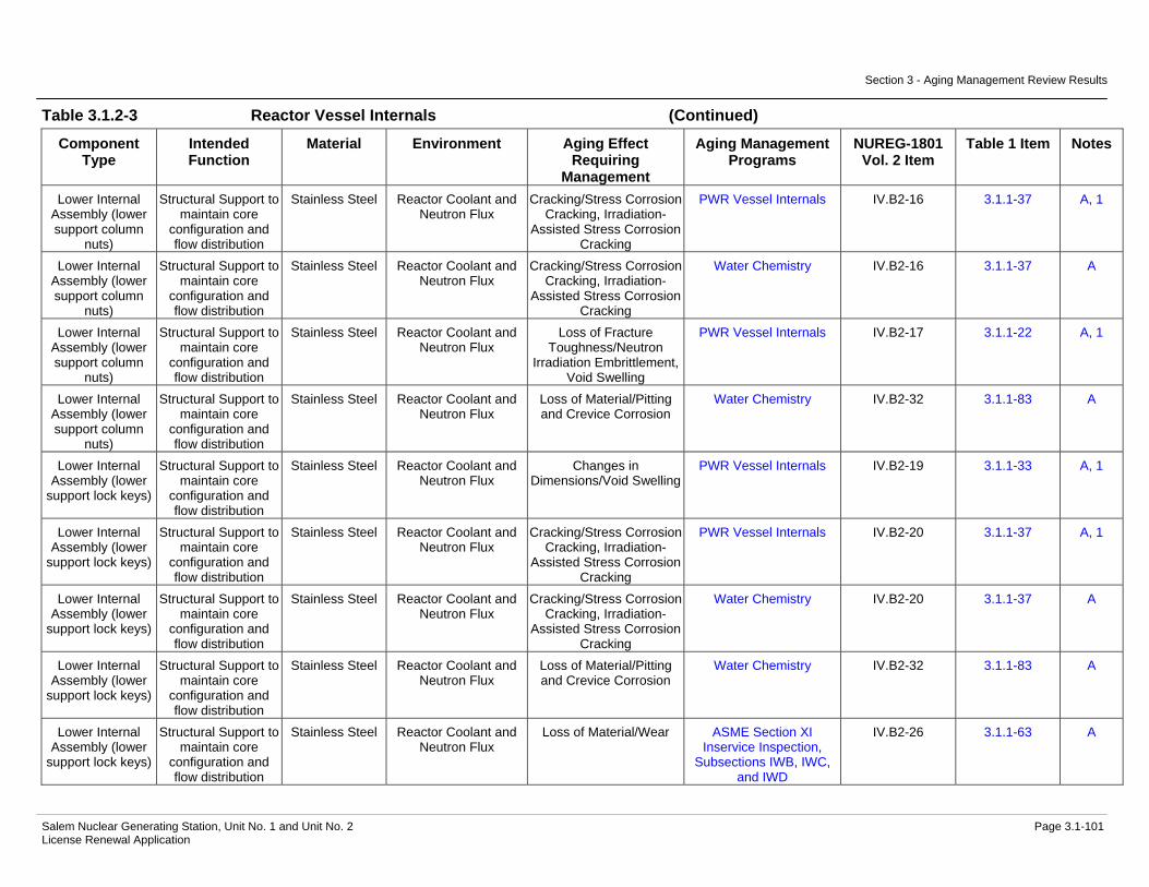
Section 3 - Aging Management Review Results
Salem Nuclear Generating Station, Unit No. 1 and Unit No. 2 Page 3.1-101 License Renewal Application
Table 3.1.2-3 Reactor Vessel Internals (Continued)
Component Type
Intended Function
Material Environment Aging Effect Requiring
Management
Aging Management Programs
NUREG-1801 Vol. 2 Item
Table 1 Item Notes
Lower Internal Assembly (lower support column
nuts)
Structural Support to maintain core
configuration and flow distribution
Stainless Steel Reactor Coolant and Neutron Flux
Cracking/Stress Corrosion Cracking, Irradiation-
Assisted Stress Corrosion Cracking
PWR Vessel Internals IV.B2-16 3.1.1-37 A, 1
Lower Internal Assembly (lower support column
nuts)
Structural Support to maintain core
configuration and flow distribution
Stainless Steel Reactor Coolant and Neutron Flux
Cracking/Stress Corrosion Cracking, Irradiation-
Assisted Stress Corrosion Cracking
Water Chemistry IV.B2-16 3.1.1-37 A
Lower Internal Assembly (lower support column
nuts)
Structural Support to maintain core
configuration and flow distribution
Stainless Steel Reactor Coolant and Neutron Flux
Loss of Fracture Toughness/Neutron
Irradiation Embrittlement, Void Swelling
PWR Vessel Internals IV.B2-17 3.1.1-22 A, 1
Lower Internal Assembly (lower support column
nuts)
Structural Support to maintain core
configuration and flow distribution
Stainless Steel Reactor Coolant and Neutron Flux
Loss of Material/Pitting and Crevice Corrosion
Water Chemistry IV.B2-32 3.1.1-83 A
Lower Internal Assembly (lower
support lock keys)
Structural Support to maintain core
configuration and flow distribution
Stainless Steel Reactor Coolant and Neutron Flux
Changes in Dimensions/Void Swelling
PWR Vessel Internals IV.B2-19 3.1.1-33 A, 1
Lower Internal Assembly (lower
support lock keys)
Structural Support to maintain core
configuration and flow distribution
Stainless Steel Reactor Coolant and Neutron Flux
Cracking/Stress Corrosion Cracking, Irradiation-
Assisted Stress Corrosion Cracking
PWR Vessel Internals IV.B2-20 3.1.1-37 A, 1
Lower Internal Assembly (lower
support lock keys)
Structural Support to maintain core
configuration and flow distribution
Stainless Steel Reactor Coolant and Neutron Flux
Cracking/Stress Corrosion Cracking, Irradiation-
Assisted Stress Corrosion Cracking
Water Chemistry IV.B2-20 3.1.1-37 A
Lower Internal Assembly (lower
support lock keys)
Structural Support to maintain core
configuration and flow distribution
Stainless Steel Reactor Coolant and Neutron Flux
Loss of Material/Pitting and Crevice Corrosion
Water Chemistry IV.B2-32 3.1.1-83 A
Lower Internal Assembly (lower
support lock keys)
Structural Support to maintain core
configuration and flow distribution
Stainless Steel Reactor Coolant and Neutron Flux
Loss of Material/Wear ASME Section XI Inservice Inspection,
Subsections IWB, IWC, and IWD
IV.B2-26 3.1.1-63 A
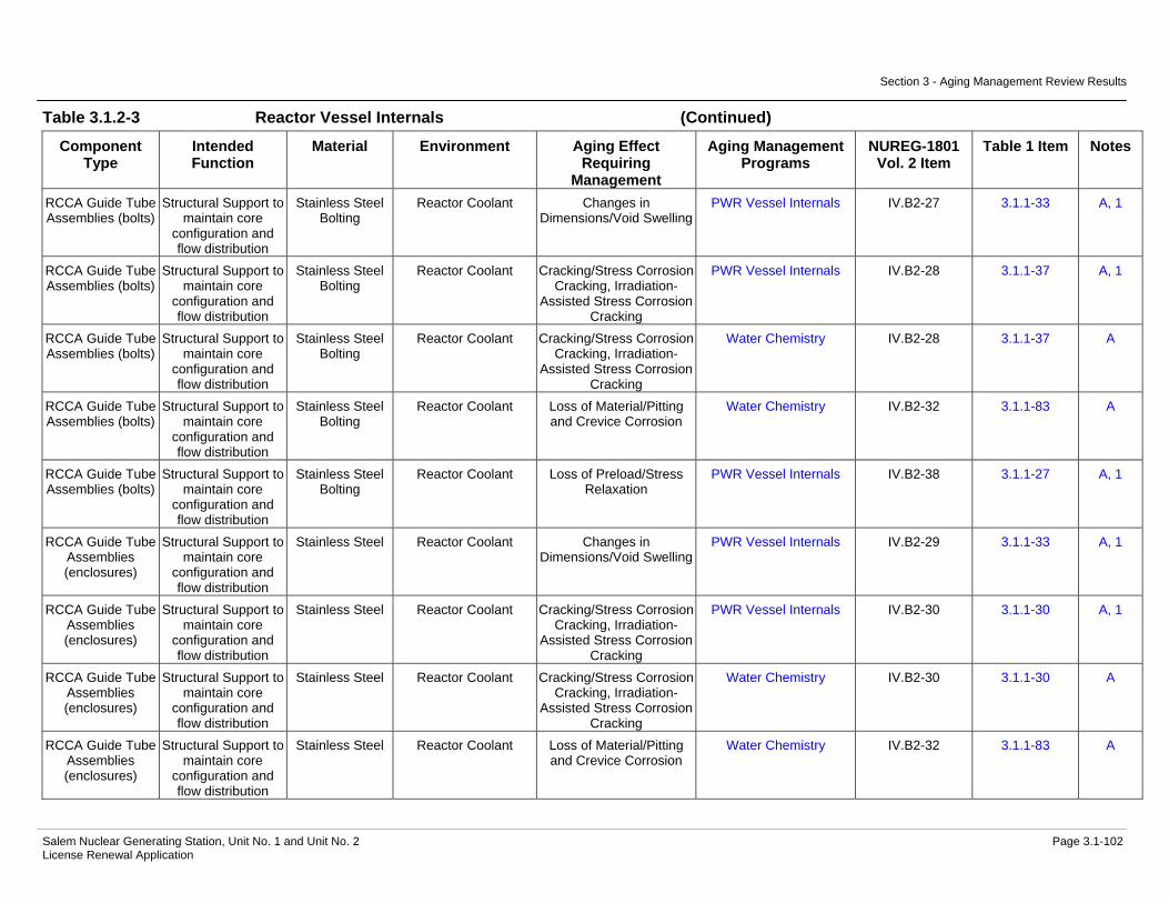
Section 3 - Aging Management Review Results
Salem Nuclear Generating Station, Unit No. 1 and Unit No. 2 Page 3.1-102 License Renewal Application
Table 3.1.2-3 Reactor Vessel Internals (Continued)
Component Type
Intended Function
Material Environment Aging Effect Requiring
Management
Aging Management Programs
NUREG-1801 Vol. 2 Item
Table 1 Item Notes
RCCA Guide Tube Assemblies (bolts)
Structural Support to maintain core
configuration and flow distribution
Stainless Steel Bolting
Reactor Coolant Changes in Dimensions/Void Swelling
PWR Vessel Internals IV.B2-27 3.1.1-33 A, 1
RCCA Guide Tube Assemblies (bolts)
Structural Support to maintain core
configuration and flow distribution
Stainless Steel Bolting
Reactor Coolant Cracking/Stress Corrosion Cracking, Irradiation-
Assisted Stress Corrosion Cracking
PWR Vessel Internals IV.B2-28 3.1.1-37 A, 1
RCCA Guide Tube Assemblies (bolts)
Structural Support to maintain core
configuration and flow distribution
Stainless Steel Bolting
Reactor Coolant Cracking/Stress Corrosion Cracking, Irradiation-
Assisted Stress Corrosion Cracking
Water Chemistry IV.B2-28 3.1.1-37 A
RCCA Guide Tube Assemblies (bolts)
Structural Support to maintain core
configuration and flow distribution
Stainless Steel Bolting
Reactor Coolant Loss of Material/Pitting and Crevice Corrosion
Water Chemistry IV.B2-32 3.1.1-83 A
RCCA Guide Tube Assemblies (bolts)
Structural Support to maintain core
configuration and flow distribution
Stainless Steel Bolting
Reactor Coolant Loss of Preload/Stress Relaxation
PWR Vessel Internals IV.B2-38 3.1.1-27 A, 1
RCCA Guide Tube Assemblies (enclosures)
Structural Support to maintain core
configuration and flow distribution
Stainless Steel Reactor Coolant Changes in Dimensions/Void Swelling
PWR Vessel Internals IV.B2-29 3.1.1-33 A, 1
RCCA Guide Tube Assemblies (enclosures)
Structural Support to maintain core
configuration and flow distribution
Stainless Steel Reactor Coolant Cracking/Stress Corrosion Cracking, Irradiation-
Assisted Stress Corrosion Cracking
PWR Vessel Internals IV.B2-30 3.1.1-30 A, 1
RCCA Guide Tube Assemblies (enclosures)
Structural Support to maintain core
configuration and flow distribution
Stainless Steel Reactor Coolant Cracking/Stress Corrosion Cracking, Irradiation-
Assisted Stress Corrosion Cracking
Water Chemistry IV.B2-30 3.1.1-30 A
RCCA Guide Tube Assemblies (enclosures)
Structural Support to maintain core
configuration and flow distribution
Stainless Steel Reactor Coolant Loss of Material/Pitting and Crevice Corrosion
Water Chemistry IV.B2-32 3.1.1-83 A

Section 3 - Aging Management Review Results
Salem Nuclear Generating Station, Unit No. 1 and Unit No. 2 Page 3.1-103 License Renewal Application
Table 3.1.2-3 Reactor Vessel Internals (Continued)
Component Type
Intended Function
Material Environment Aging Effect Requiring
Management
Aging Management Programs
NUREG-1801 Vol. 2 Item
Table 1 Item Notes
RCCA guide tube assemblies
(flexures; inserts)
Structural Support to maintain core
configuration and flow distribution
Nickel Alloy Reactor Coolant Changes in Dimensions/Void Swelling
PWR Vessel Internals IV.B2-19 3.1.1-33 C, 1
RCCA guide tube assemblies
(flexures; inserts)
Structural Support to maintain core
configuration and flow distribution
Nickel Alloy Reactor Coolant Cracking/Stress Corrosion Cracking, Irradiation-
Assisted Stress Corrosion Cracking
PWR Vessel Internals IV.B2-20 3.1.1-37 C, 1
RCCA guide tube assemblies
(flexures; inserts)
Structural Support to maintain core
configuration and flow distribution
Nickel Alloy Reactor Coolant Cracking/Stress Corrosion Cracking, Irradiation-
Assisted Stress Corrosion Cracking
Water Chemistry IV.B2-20 3.1.1-37 C
RCCA guide tube assemblies
(flexures; inserts)
Structural Support to maintain core
configuration and flow distribution
Nickel Alloy Reactor Coolant Loss of Material/Pitting and Crevice Corrosion
Water Chemistry IV.B2-32 3.1.1-83 A
RCCA guide tube assemblies
(flexures; inserts)
Structural Support to maintain core
configuration and flow distribution
Nickel Alloy Reactor Coolant Loss of Material/Wear ASME Section XI Inservice Inspection,
Subsections IWB, IWC, and IWD
H, 3
RCCA guide tube assemblies (guide
pins in tubes)
Structural Support to maintain core
configuration and flow distribution
Stainless Steel Reactor Coolant Changes in Dimensions/Void Swelling
PWR Vessel Internals IV.B2-27 3.1.1-33 A, 1
RCCA guide tube assemblies (guide
pins in tubes)
Structural Support to maintain core
configuration and flow distribution
Stainless Steel Reactor Coolant Cracking/Stress Corrosion Cracking, Irradiation-
Assisted Stress Corrosion Cracking
PWR Vessel Internals IV.B2-28 3.1.1-37 A, 1
RCCA guide tube assemblies (guide
pins in tubes)
Structural Support to maintain core
configuration and flow distribution
Stainless Steel Reactor Coolant Cracking/Stress Corrosion Cracking, Irradiation-
Assisted Stress Corrosion Cracking
Water Chemistry IV.B2-28 3.1.1-37 A
RCCA guide tube assemblies (guide
pins in tubes)
Structural Support to maintain core
configuration and flow distribution
Stainless Steel Reactor Coolant Loss of Material/Pitting and Crevice Corrosion
Water Chemistry IV.B2-32 3.1.1-83 A
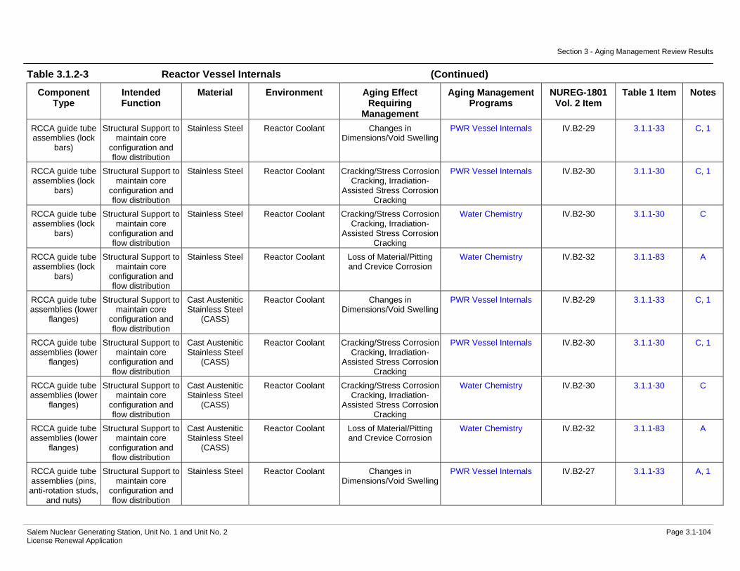
Section 3 - Aging Management Review Results
Salem Nuclear Generating Station, Unit No. 1 and Unit No. 2 Page 3.1-104 License Renewal Application
Table 3.1.2-3 Reactor Vessel Internals (Continued)
Component Type
Intended Function
Material Environment Aging Effect Requiring
Management
Aging Management Programs
NUREG-1801 Vol. 2 Item
Table 1 Item Notes
RCCA guide tube assemblies (lock
bars)
Structural Support to maintain core
configuration and flow distribution
Stainless Steel Reactor Coolant Changes in Dimensions/Void Swelling
PWR Vessel Internals IV.B2-29 3.1.1-33 C, 1
RCCA guide tube assemblies (lock
bars)
Structural Support to maintain core
configuration and flow distribution
Stainless Steel Reactor Coolant Cracking/Stress Corrosion Cracking, Irradiation-
Assisted Stress Corrosion Cracking
PWR Vessel Internals IV.B2-30 3.1.1-30 C, 1
RCCA guide tube assemblies (lock
bars)
Structural Support to maintain core
configuration and flow distribution
Stainless Steel Reactor Coolant Cracking/Stress Corrosion Cracking, Irradiation-
Assisted Stress Corrosion Cracking
Water Chemistry IV.B2-30 3.1.1-30 C
RCCA guide tube assemblies (lock
bars)
Structural Support to maintain core
configuration and flow distribution
Stainless Steel Reactor Coolant Loss of Material/Pitting and Crevice Corrosion
Water Chemistry IV.B2-32 3.1.1-83 A
RCCA guide tube assemblies (lower
flanges)
Structural Support to maintain core
configuration and flow distribution
Cast Austenitic Stainless Steel
(CASS)
Reactor Coolant Changes in Dimensions/Void Swelling
PWR Vessel Internals IV.B2-29 3.1.1-33 C, 1
RCCA guide tube assemblies (lower
flanges)
Structural Support to maintain core
configuration and flow distribution
Cast Austenitic Stainless Steel
(CASS)
Reactor Coolant Cracking/Stress Corrosion Cracking, Irradiation-
Assisted Stress Corrosion Cracking
PWR Vessel Internals IV.B2-30 3.1.1-30 C, 1
RCCA guide tube assemblies (lower
flanges)
Structural Support to maintain core
configuration and flow distribution
Cast Austenitic Stainless Steel
(CASS)
Reactor Coolant Cracking/Stress Corrosion Cracking, Irradiation-
Assisted Stress Corrosion Cracking
Water Chemistry IV.B2-30 3.1.1-30 C
RCCA guide tube assemblies (lower
flanges)
Structural Support to maintain core
configuration and flow distribution
Cast Austenitic Stainless Steel
(CASS)
Reactor Coolant Loss of Material/Pitting and Crevice Corrosion
Water Chemistry IV.B2-32 3.1.1-83 A
RCCA guide tube assemblies (pins, anti-rotation studs,
and nuts)
Structural Support to maintain core
configuration and flow distribution
Stainless Steel Reactor Coolant Changes in Dimensions/Void Swelling
PWR Vessel Internals IV.B2-27 3.1.1-33 A, 1

Section 3 - Aging Management Review Results
Salem Nuclear Generating Station, Unit No. 1 and Unit No. 2 Page 3.1-105 License Renewal Application
Table 3.1.2-3 Reactor Vessel Internals (Continued)
Component Type
Intended Function
Material Environment Aging Effect Requiring
Management
Aging Management Programs
NUREG-1801 Vol. 2 Item
Table 1 Item Notes
RCCA guide tube assemblies (pins, anti-rotation studs,
and nuts)
Structural Support to maintain core
configuration and flow distribution
Stainless Steel Reactor Coolant Cracking/Stress Corrosion Cracking, Irradiation-
Assisted Stress Corrosion Cracking
PWR Vessel Internals IV.B2-28 3.1.1-37 A, 1
RCCA guide tube assemblies (pins, anti-rotation studs,
and nuts)
Structural Support to maintain core
configuration and flow distribution
Stainless Steel Reactor Coolant Cracking/Stress Corrosion Cracking, Irradiation-
Assisted Stress Corrosion Cracking
Water Chemistry IV.B2-28 3.1.1-37 A
RCCA guide tube assemblies (pins, anti-rotation studs,
and nuts)
Structural Support to maintain core
configuration and flow distribution
Stainless Steel Reactor Coolant Loss of Material/Pitting and Crevice Corrosion
Water Chemistry IV.B2-32 3.1.1-83 A
RCCA guide tube assemblies (sheaths)
Structural Support to maintain core
configuration and flow distribution
Stainless Steel Reactor Coolant Changes in Dimensions/Void Swelling
PWR Vessel Internals IV.B2-29 3.1.1-33 C, 1
RCCA guide tube assemblies (sheaths)
Structural Support to maintain core
configuration and flow distribution
Stainless Steel Reactor Coolant Cracking/Stress Corrosion Cracking, Irradiation-
Assisted Stress Corrosion Cracking
PWR Vessel Internals IV.B2-30 3.1.1-30 C, 1
RCCA guide tube assemblies (sheaths)
Structural Support to maintain core
configuration and flow distribution
Stainless Steel Reactor Coolant Cracking/Stress Corrosion Cracking, Irradiation-
Assisted Stress Corrosion Cracking
Water Chemistry IV.B2-30 3.1.1-30 C
RCCA guide tube assemblies (sheaths)
Structural Support to maintain core
configuration and flow distribution
Stainless Steel Reactor Coolant Loss of Material/Pitting and Crevice Corrosion
Water Chemistry IV.B2-32 3.1.1-83 A
RCCA guide tube assemblies
(support pin cover plate)
Structural Support to maintain core
configuration and flow distribution
Stainless Steel Reactor Coolant Changes in Dimensions/Void Swelling
PWR Vessel Internals IV.B2-29 3.1.1-33 C, 1
RCCA guide tube assemblies
(support pin cover plate)
Structural Support to maintain core
configuration and flow distribution
Stainless Steel Reactor Coolant Cracking/Stress Corrosion Cracking, Irradiation-
Assisted Stress Corrosion Cracking
PWR Vessel Internals IV.B2-30 3.1.1-30 C, 1
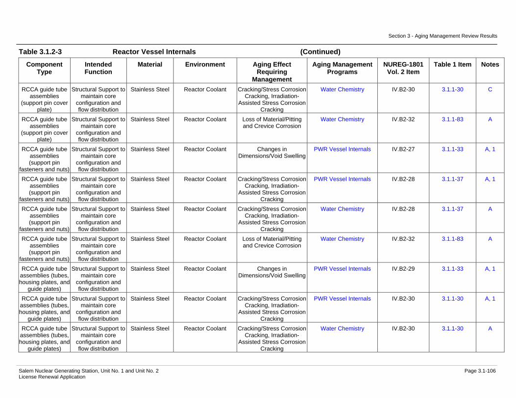
Section 3 - Aging Management Review Results
Salem Nuclear Generating Station, Unit No. 1 and Unit No. 2 Page 3.1-106 License Renewal Application
Table 3.1.2-3 Reactor Vessel Internals (Continued)
Component Type
Intended Function
Material Environment Aging Effect Requiring
Management
Aging Management Programs
NUREG-1801 Vol. 2 Item
Table 1 Item Notes
RCCA guide tube assemblies
(support pin cover plate)
Structural Support to maintain core
configuration and flow distribution
Stainless Steel Reactor Coolant Cracking/Stress Corrosion Cracking, Irradiation-
Assisted Stress Corrosion Cracking
Water Chemistry IV.B2-30 3.1.1-30 C
RCCA guide tube assemblies
(support pin cover plate)
Structural Support to maintain core
configuration and flow distribution
Stainless Steel Reactor Coolant Loss of Material/Pitting and Crevice Corrosion
Water Chemistry IV.B2-32 3.1.1-83 A
RCCA guide tube assemblies (support pin
fasteners and nuts)
Structural Support to maintain core
configuration and flow distribution
Stainless Steel Reactor Coolant Changes in Dimensions/Void Swelling
PWR Vessel Internals IV.B2-27 3.1.1-33 A, 1
RCCA guide tube assemblies (support pin
fasteners and nuts)
Structural Support to maintain core
configuration and flow distribution
Stainless Steel Reactor Coolant Cracking/Stress Corrosion Cracking, Irradiation-
Assisted Stress Corrosion Cracking
PWR Vessel Internals IV.B2-28 3.1.1-37 A, 1
RCCA guide tube assemblies (support pin
fasteners and nuts)
Structural Support to maintain core
configuration and flow distribution
Stainless Steel Reactor Coolant Cracking/Stress Corrosion Cracking, Irradiation-
Assisted Stress Corrosion Cracking
Water Chemistry IV.B2-28 3.1.1-37 A
RCCA guide tube assemblies (support pin
fasteners and nuts)
Structural Support to maintain core
configuration and flow distribution
Stainless Steel Reactor Coolant Loss of Material/Pitting and Crevice Corrosion
Water Chemistry IV.B2-32 3.1.1-83 A
RCCA guide tube assemblies (tubes, housing plates, and
guide plates)
Structural Support to maintain core
configuration and flow distribution
Stainless Steel Reactor Coolant Changes in Dimensions/Void Swelling
PWR Vessel Internals IV.B2-29 3.1.1-33 A, 1
RCCA guide tube assemblies (tubes, housing plates, and
guide plates)
Structural Support to maintain core
configuration and flow distribution
Stainless Steel Reactor Coolant Cracking/Stress Corrosion Cracking, Irradiation-
Assisted Stress Corrosion Cracking
PWR Vessel Internals IV.B2-30 3.1.1-30 A, 1
RCCA guide tube assemblies (tubes, housing plates, and
guide plates)
Structural Support to maintain core
configuration and flow distribution
Stainless Steel Reactor Coolant Cracking/Stress Corrosion Cracking, Irradiation-
Assisted Stress Corrosion Cracking
Water Chemistry IV.B2-30 3.1.1-30 A

Section 3 - Aging Management Review Results
Salem Nuclear Generating Station, Unit No. 1 and Unit No. 2 Page 3.1-107 License Renewal Application
Table 3.1.2-3 Reactor Vessel Internals (Continued)
Component Type
Intended Function
Material Environment Aging Effect Requiring
Management
Aging Management Programs
NUREG-1801 Vol. 2 Item
Table 1 Item Notes
RCCA guide tube assemblies (tubes, housing plates, and
guide plates)
Structural Support to maintain core
configuration and flow distribution
Stainless Steel Reactor Coolant Loss of Material/Pitting and Crevice Corrosion
Water Chemistry IV.B2-32 3.1.1-83 A
RCCA guide tube assemblies (upper
guide tube)
Structural Support to maintain core
configuration and flow distribution
Stainless Steel Reactor Coolant Changes in Dimensions/Void Swelling
PWR Vessel Internals IV.B2-29 3.1.1-33 A, 1
RCCA guide tube assemblies (upper
guide tube)
Structural Support to maintain core
configuration and flow distribution
Stainless Steel Reactor Coolant Cracking/Stress Corrosion Cracking, Irradiation-
Assisted Stress Corrosion Cracking
PWR Vessel Internals IV.B2-30 3.1.1-30 A, 1
RCCA guide tube assemblies (upper
guide tube)
Structural Support to maintain core
configuration and flow distribution
Stainless Steel Reactor Coolant Cracking/Stress Corrosion Cracking, Irradiation-
Assisted Stress Corrosion Cracking
Water Chemistry IV.B2-30 3.1.1-30 A
RCCA guide tube assemblies (upper
guide tube)
Structural Support to maintain core
configuration and flow distribution
Stainless Steel Reactor Coolant Loss of Material/Pitting and Crevice Corrosion
Water Chemistry IV.B2-32 3.1.1-83 A
Reactor Vessel Internals (core
support locking nut)
Structural Support to maintain core
configuration and flow distribution
Stainless Steel Reactor Coolant and Neutron Flux
Changes in Dimensions/Void Swelling
PWR Vessel Internals IV.B2-4 3.1.1-33 C, 1
Reactor Vessel Internals (core
support locking nut)
Structural Support to maintain core
configuration and flow distribution
Stainless Steel Reactor Coolant and Neutron Flux
Cracking/Stress Corrosion Cracking, Irradiation-
Assisted Stress Corrosion Cracking
PWR Vessel Internals IV.B2-10 3.1.1-30 C, 1
Reactor Vessel Internals (core
support locking nut)
Structural Support to maintain core
configuration and flow distribution
Stainless Steel Reactor Coolant and Neutron Flux
Cracking/Stress Corrosion Cracking, Irradiation-
Assisted Stress Corrosion Cracking
Water Chemistry IV.B2-10 3.1.1-30 C
Reactor Vessel Internals (core
support locking nut)
Structural Support to maintain core
configuration and flow distribution
Stainless Steel Reactor Coolant and Neutron Flux
Loss of Fracture Toughness/Neutron
Irradiation Embrittlement, Void Swelling
PWR Vessel Internals IV.B2-6 3.1.1-22 C, 1
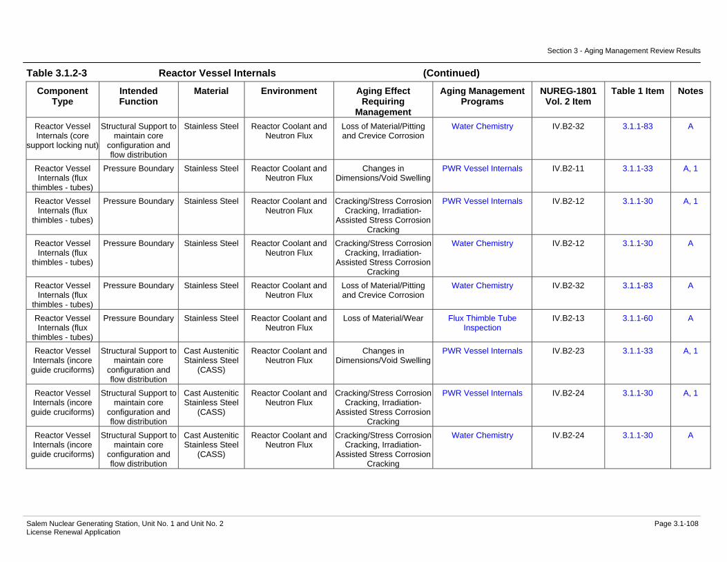
Section 3 - Aging Management Review Results
Salem Nuclear Generating Station, Unit No. 1 and Unit No. 2 Page 3.1-108 License Renewal Application
Table 3.1.2-3 Reactor Vessel Internals (Continued)
Component Type
Intended Function
Material Environment Aging Effect Requiring
Management
Aging Management Programs
NUREG-1801 Vol. 2 Item
Table 1 Item Notes
Reactor Vessel Internals (core
support locking nut)
Structural Support to maintain core
configuration and flow distribution
Stainless Steel Reactor Coolant and Neutron Flux
Loss of Material/Pitting and Crevice Corrosion
Water Chemistry IV.B2-32 3.1.1-83 A
Reactor Vessel Internals (flux
thimbles - tubes)
Pressure Boundary Stainless Steel Reactor Coolant and Neutron Flux
Changes in Dimensions/Void Swelling
PWR Vessel Internals IV.B2-11 3.1.1-33 A, 1
Reactor Vessel Internals (flux
thimbles - tubes)
Pressure Boundary Stainless Steel Reactor Coolant and Neutron Flux
Cracking/Stress Corrosion Cracking, Irradiation-
Assisted Stress Corrosion Cracking
PWR Vessel Internals IV.B2-12 3.1.1-30 A, 1
Reactor Vessel Internals (flux
thimbles - tubes)
Pressure Boundary Stainless Steel Reactor Coolant and Neutron Flux
Cracking/Stress Corrosion Cracking, Irradiation-
Assisted Stress Corrosion Cracking
Water Chemistry IV.B2-12 3.1.1-30 A
Reactor Vessel Internals (flux
thimbles - tubes)
Pressure Boundary Stainless Steel Reactor Coolant and Neutron Flux
Loss of Material/Pitting and Crevice Corrosion
Water Chemistry IV.B2-32 3.1.1-83 A
Reactor Vessel Internals (flux
thimbles - tubes)
Pressure Boundary Stainless Steel Reactor Coolant and Neutron Flux
Loss of Material/Wear Flux Thimble Tube Inspection
IV.B2-13 3.1.1-60 A
Reactor Vessel Internals (incore guide cruciforms)
Structural Support to maintain core
configuration and flow distribution
Cast Austenitic Stainless Steel
(CASS)
Reactor Coolant and Neutron Flux
Changes in Dimensions/Void Swelling
PWR Vessel Internals IV.B2-23 3.1.1-33 A, 1
Reactor Vessel Internals (incore guide cruciforms)
Structural Support to maintain core
configuration and flow distribution
Cast Austenitic Stainless Steel
(CASS)
Reactor Coolant and Neutron Flux
Cracking/Stress Corrosion Cracking, Irradiation-
Assisted Stress Corrosion Cracking
PWR Vessel Internals IV.B2-24 3.1.1-30 A, 1
Reactor Vessel Internals (incore guide cruciforms)
Structural Support to maintain core
configuration and flow distribution
Cast Austenitic Stainless Steel
(CASS)
Reactor Coolant and Neutron Flux
Cracking/Stress Corrosion Cracking, Irradiation-
Assisted Stress Corrosion Cracking
Water Chemistry IV.B2-24 3.1.1-30 A

Section 3 - Aging Management Review Results
Salem Nuclear Generating Station, Unit No. 1 and Unit No. 2 Page 3.1-109 License Renewal Application
Table 3.1.2-3 Reactor Vessel Internals (Continued)
Component Type
Intended Function
Material Environment Aging Effect Requiring
Management
Aging Management Programs
NUREG-1801 Vol. 2 Item
Table 1 Item Notes
Reactor Vessel Internals (incore guide cruciforms)
Structural Support to maintain core
configuration and flow distribution
Cast Austenitic Stainless Steel
(CASS)
Reactor Coolant and Neutron Flux
Loss of Fracture Toughness/Neutron
Irradiation Embrittlement, Void Swelling
PWR Vessel Internals IV.B2-22 3.1.1-22 A, 1
Reactor Vessel Internals (incore guide cruciforms)
Structural Support to maintain core
configuration and flow distribution
Cast Austenitic Stainless Steel
(CASS)
Reactor Coolant and Neutron Flux
Loss of Fracture Toughness/Thermal Aging
and Neutron Irradiation Embrittlement
PWR Vessel Internals IV.B2-21 3.1.1-80 E, 5
Reactor Vessel Internals (incore guide cruciforms)
Structural Support to maintain core
configuration and flow distribution
Cast Austenitic Stainless Steel
(CASS)
Reactor Coolant and Neutron Flux
Loss of Material/Pitting and Crevice Corrosion
Water Chemistry IV.B2-32 3.1.1-83 A
Reactor Vessel Internals (incore
guide tube column bodies)
Structural Support to maintain core
configuration and flow distribution
Stainless Steel Reactor Coolant and Neutron Flux
Changes in Dimensions/Void Swelling
PWR Vessel Internals IV.B2-23 3.1.1-33 A, 1
Reactor Vessel Internals (incore
guide tube column bodies)
Structural Support to maintain core
configuration and flow distribution
Stainless Steel Reactor Coolant and Neutron Flux
Cracking/Stress Corrosion Cracking, Irradiation-
Assisted Stress Corrosion Cracking
PWR Vessel Internals IV.B2-24 3.1.1-30 A, 1
Reactor Vessel Internals (incore
guide tube column bodies)
Structural Support to maintain core
configuration and flow distribution
Stainless Steel Reactor Coolant and Neutron Flux
Cracking/Stress Corrosion Cracking, Irradiation-
Assisted Stress Corrosion Cracking
Water Chemistry IV.B2-24 3.1.1-30 A
Reactor Vessel Internals (incore
guide tube column bodies)
Structural Support to maintain core
configuration and flow distribution
Stainless Steel Reactor Coolant and Neutron Flux
Loss of Fracture Toughness/Neutron
Irradiation Embrittlement, Void Swelling
PWR Vessel Internals IV.B2-22 3.1.1-22 A, 1
Reactor Vessel Internals (incore
guide tube column bodies)
Structural Support to maintain core
configuration and flow distribution
Stainless Steel Reactor Coolant and Neutron Flux
Loss of Material/Pitting and Crevice Corrosion
Water Chemistry IV.B2-32 3.1.1-83 A
Reactor Vessel Internals (incore
guide tube extensions)
Structural Support to maintain core
configuration and flow distribution
Stainless Steel Reactor Coolant and Neutron Flux
Changes in Dimensions/Void Swelling
PWR Vessel Internals IV.B2-23 3.1.1-33 A, 1

Section 3 - Aging Management Review Results
Salem Nuclear Generating Station, Unit No. 1 and Unit No. 2 Page 3.1-110 License Renewal Application
Table 3.1.2-3 Reactor Vessel Internals (Continued)
Component Type
Intended Function
Material Environment Aging Effect Requiring
Management
Aging Management Programs
NUREG-1801 Vol. 2 Item
Table 1 Item Notes
Reactor Vessel Internals (incore
guide tube extensions)
Structural Support to maintain core
configuration and flow distribution
Stainless Steel Reactor Coolant and Neutron Flux
Cracking/Stress Corrosion Cracking, Irradiation-
Assisted Stress Corrosion Cracking
PWR Vessel Internals IV.B2-24 3.1.1-30 A, 1
Reactor Vessel Internals (incore
guide tube extensions)
Structural Support to maintain core
configuration and flow distribution
Stainless Steel Reactor Coolant and Neutron Flux
Cracking/Stress Corrosion Cracking, Irradiation-
Assisted Stress Corrosion Cracking
Water Chemistry IV.B2-24 3.1.1-30 A
Reactor Vessel Internals (incore
guide tube extensions)
Structural Support to maintain core
configuration and flow distribution
Stainless Steel Reactor Coolant and Neutron Flux
Loss of Fracture Toughness/Neutron
Irradiation Embrittlement, Void Swelling
PWR Vessel Internals IV.B2-22 3.1.1-22 A, 1
Reactor Vessel Internals (incore
guide tube extensions)
Structural Support to maintain core
configuration and flow distribution
Stainless Steel Reactor Coolant and Neutron Flux
Loss of Material/Pitting and Crevice Corrosion
Water Chemistry IV.B2-32 3.1.1-83 A
Reactor Vessel Internals (incore instrument guide
extension bolt lock caps)
Structural Support to maintain core
configuration and flow distribution
Stainless Steel Reactor Coolant and Neutron Flux
Changes in Dimensions/Void Swelling
PWR Vessel Internals IV.B2-23 3.1.1-33 A, 1
Reactor Vessel Internals (incore instrument guide
extension bolt lock caps)
Structural Support to maintain core
configuration and flow distribution
Stainless Steel Reactor Coolant and Neutron Flux
Cracking/Stress Corrosion Cracking, Irradiation-
Assisted Stress Corrosion Cracking
PWR Vessel Internals IV.B2-24 3.1.1-30 A, 1
Reactor Vessel Internals (incore instrument guide
extension bolt lock caps)
Structural Support to maintain core
configuration and flow distribution
Stainless Steel Reactor Coolant and Neutron Flux
Cracking/Stress Corrosion Cracking, Irradiation-
Assisted Stress Corrosion Cracking
Water Chemistry IV.B2-24 3.1.1-30 A
Reactor Vessel Internals (incore instrument guide
extension bolt lock caps)
Structural Support to maintain core
configuration and flow distribution
Stainless Steel Reactor Coolant and Neutron Flux
Loss of Fracture Toughness/Neutron
Irradiation Embrittlement, Void Swelling
PWR Vessel Internals IV.B2-22 3.1.1-22 A, 1
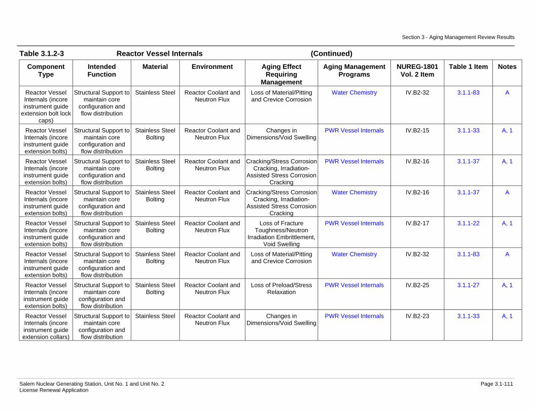
Section 3 - Aging Management Review Results
Salem Nuclear Generating Station, Unit No. 1 and Unit No. 2 Page 3.1-111 License Renewal Application
Table 3.1.2-3 Reactor Vessel Internals (Continued)
Component Type
Intended Function
Material Environment Aging Effect Requiring
Management
Aging Management Programs
NUREG-1801 Vol. 2 Item
Table 1 Item Notes
Reactor Vessel Internals (incore instrument guide
extension bolt lock caps)
Structural Support to maintain core
configuration and flow distribution
Stainless Steel Reactor Coolant and Neutron Flux
Loss of Material/Pitting and Crevice Corrosion
Water Chemistry IV.B2-32 3.1.1-83 A
Reactor Vessel Internals (incore instrument guide extension bolts)
Structural Support to maintain core
configuration and flow distribution
Stainless Steel Bolting
Reactor Coolant and Neutron Flux
Changes in Dimensions/Void Swelling
PWR Vessel Internals IV.B2-15 3.1.1-33 A, 1
Reactor Vessel Internals (incore instrument guide extension bolts)
Structural Support to maintain core
configuration and flow distribution
Stainless Steel Bolting
Reactor Coolant and Neutron Flux
Cracking/Stress Corrosion Cracking, Irradiation-
Assisted Stress Corrosion Cracking
PWR Vessel Internals IV.B2-16 3.1.1-37 A, 1
Reactor Vessel Internals (incore instrument guide extension bolts)
Structural Support to maintain core
configuration and flow distribution
Stainless Steel Bolting
Reactor Coolant and Neutron Flux
Cracking/Stress Corrosion Cracking, Irradiation-
Assisted Stress Corrosion Cracking
Water Chemistry IV.B2-16 3.1.1-37 A
Reactor Vessel Internals (incore instrument guide extension bolts)
Structural Support to maintain core
configuration and flow distribution
Stainless Steel Bolting
Reactor Coolant and Neutron Flux
Loss of Fracture Toughness/Neutron
Irradiation Embrittlement, Void Swelling
PWR Vessel Internals IV.B2-17 3.1.1-22 A, 1
Reactor Vessel Internals (incore instrument guide extension bolts)
Structural Support to maintain core
configuration and flow distribution
Stainless Steel Bolting
Reactor Coolant and Neutron Flux
Loss of Material/Pitting and Crevice Corrosion
Water Chemistry IV.B2-32 3.1.1-83 A
Reactor Vessel Internals (incore instrument guide extension bolts)
Structural Support to maintain core
configuration and flow distribution
Stainless Steel Bolting
Reactor Coolant and Neutron Flux
Loss of Preload/Stress Relaxation
PWR Vessel Internals IV.B2-25 3.1.1-27 A, 1
Reactor Vessel Internals (incore instrument guide extension collars)
Structural Support to maintain core
configuration and flow distribution
Stainless Steel Reactor Coolant and Neutron Flux
Changes in Dimensions/Void Swelling
PWR Vessel Internals IV.B2-23 3.1.1-33 A, 1

Section 3 - Aging Management Review Results
Salem Nuclear Generating Station, Unit No. 1 and Unit No. 2 Page 3.1-112 License Renewal Application
Table 3.1.2-3 Reactor Vessel Internals (Continued)
Component Type
Intended Function
Material Environment Aging Effect Requiring
Management
Aging Management Programs
NUREG-1801 Vol. 2 Item
Table 1 Item Notes
Reactor Vessel Internals (incore instrument guide extension collars)
Structural Support to maintain core
configuration and flow distribution
Stainless Steel Reactor Coolant and Neutron Flux
Cracking/Stress Corrosion Cracking, Irradiation-
Assisted Stress Corrosion Cracking
PWR Vessel Internals IV.B2-24 3.1.1-30 A, 1
Reactor Vessel Internals (incore instrument guide extension collars)
Structural Support to maintain core
configuration and flow distribution
Stainless Steel Reactor Coolant and Neutron Flux
Cracking/Stress Corrosion Cracking, Irradiation-
Assisted Stress Corrosion Cracking
Water Chemistry IV.B2-24 3.1.1-30 A
Reactor Vessel Internals (incore instrument guide extension collars)
Structural Support to maintain core
configuration and flow distribution
Stainless Steel Reactor Coolant and Neutron Flux
Loss of Fracture Toughness/Neutron
Irradiation Embrittlement, Void Swelling
PWR Vessel Internals IV.B2-22 3.1.1-22 A, 1
Reactor Vessel Internals (incore instrument guide extension collars)
Structural Support to maintain core
configuration and flow distribution
Stainless Steel Reactor Coolant and Neutron Flux
Loss of Material/Pitting and Crevice Corrosion
Water Chemistry IV.B2-32 3.1.1-83 A
Reactor Vessel Internals (incore instrument guide extension nuts)
Structural Support to maintain core
configuration and flow distribution
Stainless Steel Reactor Coolant and Neutron Flux
Changes in Dimensions/Void Swelling
PWR Vessel Internals IV.B2-23 3.1.1-33 A, 1
Reactor Vessel Internals (incore instrument guide extension nuts)
Structural Support to maintain core
configuration and flow distribution
Stainless Steel Reactor Coolant and Neutron Flux
Cracking/Stress Corrosion Cracking, Irradiation-
Assisted Stress Corrosion Cracking
PWR Vessel Internals IV.B2-24 3.1.1-30 A, 1
Reactor Vessel Internals (incore instrument guide extension nuts)
Structural Support to maintain core
configuration and flow distribution
Stainless Steel Reactor Coolant and Neutron Flux
Cracking/Stress Corrosion Cracking, Irradiation-
Assisted Stress Corrosion Cracking
Water Chemistry IV.B2-24 3.1.1-30 A
Reactor Vessel Internals (incore instrument guide extension nuts)
Structural Support to maintain core
configuration and flow distribution
Stainless Steel Reactor Coolant and Neutron Flux
Loss of Fracture Toughness/Neutron
Irradiation Embrittlement, Void Swelling
PWR Vessel Internals IV.B2-22 3.1.1-22 A, 1
Reactor Vessel Internals (incore instrument guide extension nuts)
Structural Support to maintain core
configuration and flow distribution
Stainless Steel Reactor Coolant and Neutron Flux
Loss of Material/Pitting and Crevice Corrosion
Water Chemistry IV.B2-32 3.1.1-83 A

Section 3 - Aging Management Review Results
Salem Nuclear Generating Station, Unit No. 1 and Unit No. 2 Page 3.1-113 License Renewal Application
Table 3.1.2-3 Reactor Vessel Internals (Continued)
Component Type
Intended Function
Material Environment Aging Effect Requiring
Management
Aging Management Programs
NUREG-1801 Vol. 2 Item
Table 1 Item Notes
Reactor Vessel Internals (incore instrument guide tube extension
bars)
Structural Support to maintain core
configuration and flow distribution
Stainless Steel Reactor Coolant and Neutron Flux
Changes in Dimensions/Void Swelling
PWR Vessel Internals IV.B2-23 3.1.1-33 A, 1
Reactor Vessel Internals (incore instrument guide tube extension
bars)
Structural Support to maintain core
configuration and flow distribution
Stainless Steel Reactor Coolant and Neutron Flux
Cracking/Stress Corrosion Cracking, Irradiation-
Assisted Stress Corrosion Cracking
PWR Vessel Internals IV.B2-24 3.1.1-30 A, 1
Reactor Vessel Internals (incore instrument guide tube extension
bars)
Structural Support to maintain core
configuration and flow distribution
Stainless Steel Reactor Coolant and Neutron Flux
Cracking/Stress Corrosion Cracking, Irradiation-
Assisted Stress Corrosion Cracking
Water Chemistry IV.B2-24 3.1.1-30 A
Reactor Vessel Internals (incore instrument guide tube extension
bars)
Structural Support to maintain core
configuration and flow distribution
Stainless Steel Reactor Coolant and Neutron Flux
Loss of Fracture Toughness/Neutron
Irradiation Embrittlement, Void Swelling
PWR Vessel Internals IV.B2-22 3.1.1-22 A, 1
Reactor Vessel Internals (incore instrument guide tube extension
bars)
Structural Support to maintain core
configuration and flow distribution
Stainless Steel Reactor Coolant and Neutron Flux
Loss of Material/Pitting and Crevice Corrosion
Water Chemistry IV.B2-32 3.1.1-83 A
Reactor Vessel Internals (manway cover assembly)
Pressure Boundary Stainless Steel Reactor Coolant and Neutron Flux
Changes in Dimensions/Void Swelling
PWR Vessel Internals IV.B2-23 3.1.1-33 A, 1
Reactor Vessel Internals (manway cover assembly)
Pressure Boundary Stainless Steel Reactor Coolant and Neutron Flux
Cracking/Stress Corrosion Cracking, Irradiation-
Assisted Stress Corrosion Cracking
PWR Vessel Internals IV.B2-24 3.1.1-30 A, 1
Reactor Vessel Internals (manway cover assembly)
Pressure Boundary Stainless Steel Reactor Coolant and Neutron Flux
Cracking/Stress Corrosion Cracking, Irradiation-
Assisted Stress Corrosion Cracking
Water Chemistry IV.B2-24 3.1.1-30 A
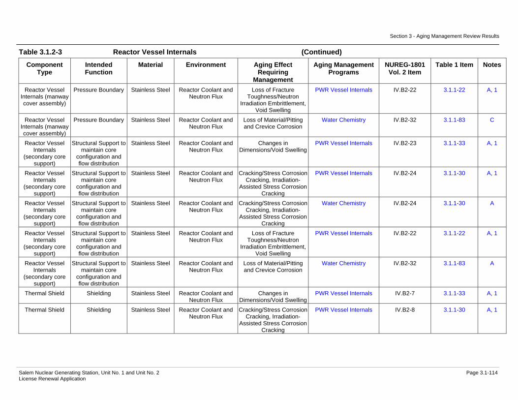
Section 3 - Aging Management Review Results
Salem Nuclear Generating Station, Unit No. 1 and Unit No. 2 Page 3.1-114 License Renewal Application
Table 3.1.2-3 Reactor Vessel Internals (Continued)
Component Type
Intended Function
Material Environment Aging Effect Requiring
Management
Aging Management Programs
NUREG-1801 Vol. 2 Item
Table 1 Item Notes
Reactor Vessel Internals (manway cover assembly)
Pressure Boundary Stainless Steel Reactor Coolant and Neutron Flux
Loss of Fracture Toughness/Neutron
Irradiation Embrittlement, Void Swelling
PWR Vessel Internals IV.B2-22 3.1.1-22 A, 1
Reactor Vessel Internals (manway cover assembly)
Pressure Boundary Stainless Steel Reactor Coolant and Neutron Flux
Loss of Material/Pitting and Crevice Corrosion
Water Chemistry IV.B2-32 3.1.1-83 C
Reactor Vessel Internals
(secondary core support)
Structural Support to maintain core
configuration and flow distribution
Stainless Steel Reactor Coolant and Neutron Flux
Changes in Dimensions/Void Swelling
PWR Vessel Internals IV.B2-23 3.1.1-33 A, 1
Reactor Vessel Internals
(secondary core support)
Structural Support to maintain core
configuration and flow distribution
Stainless Steel Reactor Coolant and Neutron Flux
Cracking/Stress Corrosion Cracking, Irradiation-
Assisted Stress Corrosion Cracking
PWR Vessel Internals IV.B2-24 3.1.1-30 A, 1
Reactor Vessel Internals
(secondary core support)
Structural Support to maintain core
configuration and flow distribution
Stainless Steel Reactor Coolant and Neutron Flux
Cracking/Stress Corrosion Cracking, Irradiation-
Assisted Stress Corrosion Cracking
Water Chemistry IV.B2-24 3.1.1-30 A
Reactor Vessel Internals
(secondary core support)
Structural Support to maintain core
configuration and flow distribution
Stainless Steel Reactor Coolant and Neutron Flux
Loss of Fracture Toughness/Neutron
Irradiation Embrittlement, Void Swelling
PWR Vessel Internals IV.B2-22 3.1.1-22 A, 1
Reactor Vessel Internals
(secondary core support)
Structural Support to maintain core
configuration and flow distribution
Stainless Steel Reactor Coolant and Neutron Flux
Loss of Material/Pitting and Crevice Corrosion
Water Chemistry IV.B2-32 3.1.1-83 A
Thermal Shield Shielding Stainless Steel Reactor Coolant and Neutron Flux
Changes in Dimensions/Void Swelling
PWR Vessel Internals IV.B2-7 3.1.1-33 A, 1
Thermal Shield Shielding Stainless Steel Reactor Coolant and Neutron Flux
Cracking/Stress Corrosion Cracking, Irradiation-
Assisted Stress Corrosion Cracking
PWR Vessel Internals IV.B2-8 3.1.1-30 A, 1

Section 3 - Aging Management Review Results
Salem Nuclear Generating Station, Unit No. 1 and Unit No. 2 Page 3.1-115 License Renewal Application
Table 3.1.2-3 Reactor Vessel Internals (Continued)
Component Type
Intended Function
Material Environment Aging Effect Requiring
Management
Aging Management Programs
NUREG-1801 Vol. 2 Item
Table 1 Item Notes
Thermal Shield Shielding Stainless Steel Reactor Coolant and Neutron Flux
Cracking/Stress Corrosion Cracking, Irradiation-
Assisted Stress Corrosion Cracking
Water Chemistry IV.B2-8 3.1.1-30 A
Thermal Shield Shielding Stainless Steel Reactor Coolant and Neutron Flux
Loss of Fracture Toughness/Neutron
Irradiation Embrittlement, Void Swelling
PWR Vessel Internals IV.B2-9 3.1.1-22 A, 1
Thermal Shield Shielding Stainless Steel Reactor Coolant and Neutron Flux
Loss of Material/Pitting and Crevice Corrosion
Water Chemistry IV.B2-32 3.1.1-83 C
Thermal Shield (adjustment plugs)
Structural Support to maintain core
configuration and flow distribution
Stainless Steel Reactor Coolant and Neutron Flux
Changes in Dimensions/Void Swelling
PWR Vessel Internals IV.B2-7 3.1.1-33 A, 1
Thermal Shield (adjustment plugs)
Structural Support to maintain core
configuration and flow distribution
Stainless Steel Reactor Coolant and Neutron Flux
Cracking/Stress Corrosion Cracking, Irradiation-
Assisted Stress Corrosion Cracking
PWR Vessel Internals IV.B2-8 3.1.1-30 A, 1
Thermal Shield (adjustment plugs)
Structural Support to maintain core
configuration and flow distribution
Stainless Steel Reactor Coolant and Neutron Flux
Cracking/Stress Corrosion Cracking, Irradiation-
Assisted Stress Corrosion Cracking
Water Chemistry IV.B2-8 3.1.1-30 A
Thermal Shield (adjustment plugs)
Structural Support to maintain core
configuration and flow distribution
Stainless Steel Reactor Coolant and Neutron Flux
Loss of Fracture Toughness/Neutron
Irradiation Embrittlement, Void Swelling
PWR Vessel Internals IV.B2-9 3.1.1-22 A, 1
Thermal Shield (adjustment plugs)
Structural Support to maintain core
configuration and flow distribution
Stainless Steel Reactor Coolant and Neutron Flux
Loss of Material/Pitting and Crevice Corrosion
Water Chemistry IV.B2-32 3.1.1-83 C
Thermal Shield (bolts and dowels)
Structural Support to maintain core
configuration and flow distribution
Stainless Steel Bolting
Reactor Coolant and Neutron Flux
Changes in Dimensions/Void Swelling
PWR Vessel Internals IV.B2-4 3.1.1-33 C, 1

Section 3 - Aging Management Review Results
Salem Nuclear Generating Station, Unit No. 1 and Unit No. 2 Page 3.1-116 License Renewal Application
Table 3.1.2-3 Reactor Vessel Internals (Continued)
Component Type
Intended Function
Material Environment Aging Effect Requiring
Management
Aging Management Programs
NUREG-1801 Vol. 2 Item
Table 1 Item Notes
Thermal Shield (bolts and dowels)
Structural Support to maintain core
configuration and flow distribution
Stainless Steel Bolting
Reactor Coolant and Neutron Flux
Cracking/Stress Corrosion Cracking, Irradiation-
Assisted Stress Corrosion Cracking
PWR Vessel Internals IV.B2-10 3.1.1-30 C, 1
Thermal Shield (bolts and dowels)
Structural Support to maintain core
configuration and flow distribution
Stainless Steel Bolting
Reactor Coolant and Neutron Flux
Cracking/Stress Corrosion Cracking, Irradiation-
Assisted Stress Corrosion Cracking
Water Chemistry IV.B2-10 3.1.1-30 C
Thermal Shield (bolts and dowels)
Structural Support to maintain core
configuration and flow distribution
Stainless Steel Bolting
Reactor Coolant and Neutron Flux
Loss of Fracture Toughness/Neutron
Irradiation Embrittlement, Void Swelling
PWR Vessel Internals IV.B2-6 3.1.1-22 C, 1
Thermal Shield (bolts and dowels)
Structural Support to maintain core
configuration and flow distribution
Stainless Steel Bolting
Reactor Coolant and Neutron Flux
Loss of Material/Pitting and Crevice Corrosion
Water Chemistry IV.B2-32 3.1.1-83 C
Thermal Shield (bolts and dowels)
Structural Support to maintain core
configuration and flow distribution
Stainless Steel Bolting
Reactor Coolant and Neutron Flux
Loss of Preload/Stress Relaxation
PWR Vessel Internals IV.B2-5 3.1.1-27 C, 1
Upper Internals Assembly (beam
and ribs bolts)
Structural Support to maintain core
configuration and flow distribution
Stainless Steel Bolting
Reactor Coolant Changes in Dimensions/Void Swelling
PWR Vessel Internals IV.B2-39 3.1.1-33 A, 1
Upper Internals Assembly (beam
and ribs bolts)
Structural Support to maintain core
configuration and flow distribution
Stainless Steel Bolting
Reactor Coolant Cracking/Stress Corrosion Cracking, Irradiation-
Assisted Stress Corrosion Cracking
PWR Vessel Internals IV.B2-40 3.1.1-37 A, 1
Upper Internals Assembly (beam
and ribs bolts)
Structural Support to maintain core
configuration and flow distribution
Stainless Steel Bolting
Reactor Coolant Cracking/Stress Corrosion Cracking, Irradiation-
Assisted Stress Corrosion Cracking
Water Chemistry IV.B2-40 3.1.1-37 A
Upper Internals Assembly (beam
and ribs bolts)
Structural Support to maintain core
configuration and flow distribution
Stainless Steel Bolting
Reactor Coolant Loss of Material/Pitting and Crevice Corrosion
Water Chemistry IV.B2-32 3.1.1-83 A

Section 3 - Aging Management Review Results
Salem Nuclear Generating Station, Unit No. 1 and Unit No. 2 Page 3.1-117 License Renewal Application
Table 3.1.2-3 Reactor Vessel Internals (Continued)
Component Type
Intended Function
Material Environment Aging Effect Requiring
Management
Aging Management Programs
NUREG-1801 Vol. 2 Item
Table 1 Item Notes
Upper Internals Assembly (beam
and ribs bolts)
Structural Support to maintain core
configuration and flow distribution
Stainless Steel Bolting
Reactor Coolant Loss of Preload/Stress Relaxation
PWR Vessel Internals IV.B2-38 3.1.1-27 A, 1
Upper Internals Assembly (beam
and ribs lock keys)
Structural Support to maintain core
configuration and flow distribution
Stainless Steel Reactor Coolant Changes in Dimensions/Void Swelling
PWR Vessel Internals IV.B2-35 3.1.1-33 A, 1
Upper Internals Assembly (beam
and ribs lock keys)
Structural Support to maintain core
configuration and flow distribution
Stainless Steel Reactor Coolant Cracking/Stress Corrosion Cracking, Irradiation-
Assisted Stress Corrosion Cracking
PWR Vessel Internals IV.B2-36 3.1.1-30 A, 1
Upper Internals Assembly (beam
and ribs lock keys)
Structural Support to maintain core
configuration and flow distribution
Stainless Steel Reactor Coolant Cracking/Stress Corrosion Cracking, Irradiation-
Assisted Stress Corrosion Cracking
Water Chemistry IV.B2-36 3.1.1-30 A
Upper Internals Assembly (beam
and ribs lock keys)
Structural Support to maintain core
configuration and flow distribution
Stainless Steel Reactor Coolant Loss of Material/Pitting and Crevice Corrosion
Water Chemistry IV.B2-32 3.1.1-83 A
Upper Internals Assembly (beam
and ribs lock keys)
Structural Support to maintain core
configuration and flow distribution
Stainless Steel Reactor Coolant Loss of Material/Wear ASME Section XI Inservice Inspection,
Subsections IWB, IWC, and IWD
IV.B2-26 3.1.1-63 C
Upper Internals Assembly (capped top thermocouple
columns)
Pressure Boundary Stainless Steel Reactor Coolant Changes in Dimensions/Void Swelling
PWR Vessel Internals IV.B2-35 3.1.1-33 A, 1
Upper Internals Assembly (capped top thermocouple
columns)
Pressure Boundary Stainless Steel Reactor Coolant Cracking/Stress Corrosion Cracking, Irradiation-
Assisted Stress Corrosion Cracking
PWR Vessel Internals IV.B2-36 3.1.1-30 A, 1
Upper Internals Assembly (capped top thermocouple
columns)
Pressure Boundary Stainless Steel Reactor Coolant Cracking/Stress Corrosion Cracking, Irradiation-
Assisted Stress Corrosion Cracking
Water Chemistry IV.B2-36 3.1.1-30 A

Section 3 - Aging Management Review Results
Salem Nuclear Generating Station, Unit No. 1 and Unit No. 2 Page 3.1-118 License Renewal Application
Table 3.1.2-3 Reactor Vessel Internals (Continued)
Component Type
Intended Function
Material Environment Aging Effect Requiring
Management
Aging Management Programs
NUREG-1801 Vol. 2 Item
Table 1 Item Notes
Upper Internals Assembly (capped top thermocouple
columns)
Pressure Boundary Stainless Steel Reactor Coolant Loss of Material/Pitting and Crevice Corrosion
Water Chemistry IV.B2-32 3.1.1-83 A
Upper Internals Assembly (deep
beam rib and stiffener, and ribs)
Structural Support to maintain core
configuration and flow distribution
Stainless Steel Reactor Coolant Changes in Dimensions/Void Swelling
PWR Vessel Internals IV.B2-35 3.1.1-33 A, 1
Upper Internals Assembly (deep
beam rib and stiffener, and ribs)
Structural Support to maintain core
configuration and flow distribution
Stainless Steel Reactor Coolant Cracking/Stress Corrosion Cracking, Irradiation-
Assisted Stress Corrosion Cracking
PWR Vessel Internals IV.B2-36 3.1.1-30 A, 1
Upper Internals Assembly (deep
beam rib and stiffener, and ribs)
Structural Support to maintain core
configuration and flow distribution
Stainless Steel Reactor Coolant Cracking/Stress Corrosion Cracking, Irradiation-
Assisted Stress Corrosion Cracking
Water Chemistry IV.B2-36 3.1.1-30 A
Upper Internals Assembly (deep
beam rib and stiffener, and ribs)
Structural Support to maintain core
configuration and flow distribution
Stainless Steel Reactor Coolant Loss of Material/Pitting and Crevice Corrosion
Water Chemistry IV.B2-32 3.1.1-83 A
Upper Internals Assembly (fuel
assembly locating pins)
Structural Support to maintain core
configuration and flow distribution
Stainless Steel Reactor Coolant Changes in Dimensions/Void Swelling
PWR Vessel Internals IV.B2-39 3.1.1-33 A, 1
Upper Internals Assembly (fuel
assembly locating pins)
Structural Support to maintain core
configuration and flow distribution
Stainless Steel Reactor Coolant Cracking/Stress Corrosion Cracking, Irradiation-
Assisted Stress Corrosion Cracking
PWR Vessel Internals IV.B2-40 3.1.1-37 A, 1
Upper Internals Assembly (fuel
assembly locating pins)
Structural Support to maintain core
configuration and flow distribution
Stainless Steel Reactor Coolant Cracking/Stress Corrosion Cracking, Irradiation-
Assisted Stress Corrosion Cracking
Water Chemistry IV.B2-40 3.1.1-37 A
Upper Internals Assembly (fuel
assembly locating pins)
Structural Support to maintain core
configuration and flow distribution
Stainless Steel Reactor Coolant Loss of Material/Pitting and Crevice Corrosion
Water Chemistry IV.B2-32 3.1.1-83 A

Section 3 - Aging Management Review Results
Salem Nuclear Generating Station, Unit No. 1 and Unit No. 2 Page 3.1-119 License Renewal Application
Table 3.1.2-3 Reactor Vessel Internals (Continued)
Component Type
Intended Function
Material Environment Aging Effect Requiring
Management
Aging Management Programs
NUREG-1801 Vol. 2 Item
Table 1 Item Notes
Upper Internals Assembly (head to vessel alignment pin bolt locking
caps)
Structural Support to maintain core
configuration and flow distribution
Stainless Steel Reactor Coolant Changes in Dimensions/Void Swelling
PWR Vessel Internals IV.B2-35 3.1.1-33 A, 1
Upper Internals Assembly (head to vessel alignment pin bolt locking
caps)
Structural Support to maintain core
configuration and flow distribution
Stainless Steel Reactor Coolant Cracking/Stress Corrosion Cracking, Irradiation-
Assisted Stress Corrosion Cracking
PWR Vessel Internals IV.B2-36 3.1.1-30 A, 1
Upper Internals Assembly (head to vessel alignment pin bolt locking
caps)
Structural Support to maintain core
configuration and flow distribution
Stainless Steel Reactor Coolant Cracking/Stress Corrosion Cracking, Irradiation-
Assisted Stress Corrosion Cracking
Water Chemistry IV.B2-36 3.1.1-30 A
Upper Internals Assembly (head to vessel alignment pin bolt locking
caps)
Structural Support to maintain core
configuration and flow distribution
Stainless Steel Reactor Coolant Loss of Material/Pitting and Crevice Corrosion
Water Chemistry IV.B2-32 3.1.1-83 A
Upper Internals Assembly (head to vessel alignment
pin bolts)
Structural Support to maintain core
configuration and flow distribution
Stainless Steel Bolting
Reactor Coolant Changes in Dimensions/Void Swelling
PWR Vessel Internals IV.B2-39 3.1.1-33 A, 1
Upper Internals Assembly (head to vessel alignment
pin bolts)
Structural Support to maintain core
configuration and flow distribution
Stainless Steel Bolting
Reactor Coolant Cracking/Stress Corrosion Cracking, Irradiation-
Assisted Stress Corrosion Cracking
PWR Vessel Internals IV.B2-40 3.1.1-37 A, 1
Upper Internals Assembly (head to vessel alignment
pin bolts)
Structural Support to maintain core
configuration and flow distribution
Stainless Steel Bolting
Reactor Coolant Cracking/Stress Corrosion Cracking, Irradiation-
Assisted Stress Corrosion Cracking
Water Chemistry IV.B2-40 3.1.1-37 A
Upper Internals Assembly (head to vessel alignment
pin bolts)
Structural Support to maintain core
configuration and flow distribution
Stainless Steel Bolting
Reactor Coolant Loss of Material/Pitting and Crevice Corrosion
Water Chemistry IV.B2-32 3.1.1-83 A

Section 3 - Aging Management Review Results
Salem Nuclear Generating Station, Unit No. 1 and Unit No. 2 Page 3.1-120 License Renewal Application
Table 3.1.2-3 Reactor Vessel Internals (Continued)
Component Type
Intended Function
Material Environment Aging Effect Requiring
Management
Aging Management Programs
NUREG-1801 Vol. 2 Item
Table 1 Item Notes
Upper Internals Assembly (head to vessel alignment
pin bolts)
Structural Support to maintain core
configuration and flow distribution
Stainless Steel Bolting
Reactor Coolant Loss of Preload/Stress Relaxation
PWR Vessel Internals IV.B2-38 3.1.1-27 A, 1
Upper Internals Assembly (head to vessel alignment
pins)
Structural Support to maintain core
configuration and flow distribution
Stainless Steel Reactor Coolant Changes in Dimensions/Void Swelling
PWR Vessel Internals IV.B2-39 3.1.1-33 A, 1
Upper Internals Assembly (head to vessel alignment
pins)
Structural Support to maintain core
configuration and flow distribution
Stainless Steel Reactor Coolant Cracking/Stress Corrosion Cracking, Irradiation-
Assisted Stress Corrosion Cracking
PWR Vessel Internals IV.B2-40 3.1.1-37 A, 1
Upper Internals Assembly (head to vessel alignment
pins)
Structural Support to maintain core
configuration and flow distribution
Stainless Steel Reactor Coolant Cracking/Stress Corrosion Cracking, Irradiation-
Assisted Stress Corrosion Cracking
Water Chemistry IV.B2-40 3.1.1-37 A
Upper Internals Assembly (head to vessel alignment
pins)
Structural Support to maintain core
configuration and flow distribution
Stainless Steel Reactor Coolant Loss of Material/Pitting and Crevice Corrosion
Water Chemistry IV.B2-32 3.1.1-83 A
Upper Internals Assembly (head to vessel alignment
pins)
Structural Support to maintain core
configuration and flow distribution
Stainless Steel Reactor Coolant Loss of Material/Wear ASME Section XI Inservice Inspection,
Subsections IWB, IWC, and IWD
IV.B2-34 3.1.1-63 A
Upper Internals Assembly (hold
down spring)
Structural Support to maintain core
configuration and flow distribution
Stainless Steel Reactor Coolant Changes in Dimensions/Void Swelling
PWR Vessel Internals IV.B2-41 3.1.1-33 A, 1
Upper Internals Assembly (hold
down spring)
Structural Support to maintain core
configuration and flow distribution
Stainless Steel Reactor Coolant Cracking/Stress Corrosion Cracking, Irradiation-
Assisted Stress Corrosion Cracking
PWR Vessel Internals IV.B2-42 3.1.1-30 A, 1
Upper Internals Assembly (hold
down spring)
Structural Support to maintain core
configuration and flow distribution
Stainless Steel Reactor Coolant Cracking/Stress Corrosion Cracking, Irradiation-
Assisted Stress Corrosion Cracking
Water Chemistry IV.B2-42 3.1.1-30 A
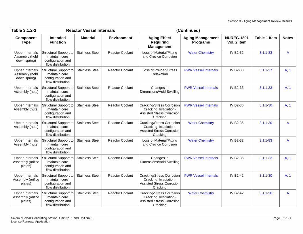
Section 3 - Aging Management Review Results
Salem Nuclear Generating Station, Unit No. 1 and Unit No. 2 Page 3.1-121 License Renewal Application
Table 3.1.2-3 Reactor Vessel Internals (Continued)
Component Type
Intended Function
Material Environment Aging Effect Requiring
Management
Aging Management Programs
NUREG-1801 Vol. 2 Item
Table 1 Item Notes
Upper Internals Assembly (hold
down spring)
Structural Support to maintain core
configuration and flow distribution
Stainless Steel Reactor Coolant Loss of Material/Pitting and Crevice Corrosion
Water Chemistry IV.B2-32 3.1.1-83 A
Upper Internals Assembly (hold
down spring)
Structural Support to maintain core
configuration and flow distribution
Stainless Steel Reactor Coolant Loss of Preload/Stress Relaxation
PWR Vessel Internals IV.B2-33 3.1.1-27 A, 1
Upper Internals Assembly (nuts)
Structural Support to maintain core
configuration and flow distribution
Stainless Steel Reactor Coolant Changes in Dimensions/Void Swelling
PWR Vessel Internals IV.B2-35 3.1.1-33 A, 1
Upper Internals Assembly (nuts)
Structural Support to maintain core
configuration and flow distribution
Stainless Steel Reactor Coolant Cracking/Stress Corrosion Cracking, Irradiation-
Assisted Stress Corrosion Cracking
PWR Vessel Internals IV.B2-36 3.1.1-30 A, 1
Upper Internals Assembly (nuts)
Structural Support to maintain core
configuration and flow distribution
Stainless Steel Reactor Coolant Cracking/Stress Corrosion Cracking, Irradiation-
Assisted Stress Corrosion Cracking
Water Chemistry IV.B2-36 3.1.1-30 A
Upper Internals Assembly (nuts)
Structural Support to maintain core
configuration and flow distribution
Stainless Steel Reactor Coolant Loss of Material/Pitting and Crevice Corrosion
Water Chemistry IV.B2-32 3.1.1-83 A
Upper Internals Assembly (orifice
plates)
Structural Support to maintain core
configuration and flow distribution
Stainless Steel Reactor Coolant Changes in Dimensions/Void Swelling
PWR Vessel Internals IV.B2-35 3.1.1-33 A, 1
Upper Internals Assembly (orifice
plates)
Structural Support to maintain core
configuration and flow distribution
Stainless Steel Reactor Coolant Cracking/Stress Corrosion Cracking, Irradiation-
Assisted Stress Corrosion Cracking
PWR Vessel Internals IV.B2-42 3.1.1-30 A, 1
Upper Internals Assembly (orifice
plates)
Structural Support to maintain core
configuration and flow distribution
Stainless Steel Reactor Coolant Cracking/Stress Corrosion Cracking, Irradiation-
Assisted Stress Corrosion Cracking
Water Chemistry IV.B2-42 3.1.1-30 A

Section 3 - Aging Management Review Results
Salem Nuclear Generating Station, Unit No. 1 and Unit No. 2 Page 3.1-122 License Renewal Application
Table 3.1.2-3 Reactor Vessel Internals (Continued)
Component Type
Intended Function
Material Environment Aging Effect Requiring
Management
Aging Management Programs
NUREG-1801 Vol. 2 Item
Table 1 Item Notes
Upper Internals Assembly (orifice
plates)
Structural Support to maintain core
configuration and flow distribution
Stainless Steel Reactor Coolant Loss of Material/Pitting and Crevice Corrosion
Water Chemistry IV.B2-32 3.1.1-83 A
Upper Internals Assembly (static
flow mixers)
Structural Support to maintain core
configuration and flow distribution
Cast Austenitic Stainless Steel
(CASS)
Reactor Coolant Changes in Dimensions/Void Swelling
PWR Vessel Internals IV.B2-41 3.1.1-33 A, 1
Upper Internals Assembly (static
flow mixers)
Structural Support to maintain core
configuration and flow distribution
Cast Austenitic Stainless Steel
(CASS)
Reactor Coolant Cracking/Stress Corrosion Cracking, Irradiation-
Assisted Stress Corrosion Cracking
PWR Vessel Internals IV.B2-42 3.1.1-30 A, 1
Upper Internals Assembly (static
flow mixers)
Structural Support to maintain core
configuration and flow distribution
Cast Austenitic Stainless Steel
(CASS)
Reactor Coolant Cracking/Stress Corrosion Cracking, Irradiation-
Assisted Stress Corrosion Cracking
Water Chemistry IV.B2-42 3.1.1-30 A
Upper Internals Assembly (static
flow mixers)
Structural Support to maintain core
configuration and flow distribution
Cast Austenitic Stainless Steel
(CASS)
Reactor Coolant Loss of Material/Pitting and Crevice Corrosion
Water Chemistry IV.B2-32 3.1.1-83 A
Upper Internals Assembly (upper
core plate alignment pins)
Structural Support to maintain core
configuration and flow distribution
Stainless Steel Reactor Coolant Changes in Dimensions/Void Swelling
PWR Vessel Internals IV.B2-39 3.1.1-33 A, 1
Upper Internals Assembly (upper
core plate alignment pins)
Structural Support to maintain core
configuration and flow distribution
Stainless Steel Reactor Coolant Cracking/Stress Corrosion Cracking, Irradiation-
Assisted Stress Corrosion Cracking
PWR Vessel Internals IV.B2-40 3.1.1-37 A, 1
Upper Internals Assembly (upper
core plate alignment pins)
Structural Support to maintain core
configuration and flow distribution
Stainless Steel Reactor Coolant Cracking/Stress Corrosion Cracking, Irradiation-
Assisted Stress Corrosion Cracking
Water Chemistry IV.B2-40 3.1.1-37 A
Upper Internals Assembly (upper
core plate alignment pins)
Structural Support to maintain core
configuration and flow distribution
Stainless Steel Reactor Coolant Loss of Material/Pitting and Crevice Corrosion
Water Chemistry IV.B2-32 3.1.1-83 A

Section 3 - Aging Management Review Results
Salem Nuclear Generating Station, Unit No. 1 and Unit No. 2 Page 3.1-123 License Renewal Application
Table 3.1.2-3 Reactor Vessel Internals (Continued)
Component Type
Intended Function
Material Environment Aging Effect Requiring
Management
Aging Management Programs
NUREG-1801 Vol. 2 Item
Table 1 Item Notes
Upper Internals Assembly (upper
core plate alignment pins)
Structural Support to maintain core
configuration and flow distribution
Stainless Steel Reactor Coolant Loss of Material/Wear ASME Section XI Inservice Inspection,
Subsections IWB, IWC, and IWD
IV.B2-34 3.1.1-63 A
Upper Internals Assembly (upper core plate, insert, spacer ring, upper support plate, and upper support ring
or skirt)
Structural Support to maintain core
configuration and flow distribution
Stainless Steel Reactor Coolant Changes in Dimensions/Void Swelling
PWR Vessel Internals IV.B2-41 3.1.1-33 A, 1
Upper Internals Assembly (upper core plate, insert, spacer ring, upper support plate, and upper support ring
or skirt)
Structural Support to maintain core
configuration and flow distribution
Stainless Steel Reactor Coolant Cracking/Stress Corrosion Cracking, Irradiation-
Assisted Stress Corrosion Cracking
PWR Vessel Internals IV.B2-42 3.1.1-30 A, 1
Upper Internals Assembly (upper core plate, insert, spacer ring, upper support plate, and upper support ring
or skirt)
Structural Support to maintain core
configuration and flow distribution
Stainless Steel Reactor Coolant Cracking/Stress Corrosion Cracking, Irradiation-
Assisted Stress Corrosion Cracking
Water Chemistry IV.B2-42 3.1.1-30 A
Upper Internals Assembly (upper core plate, insert, spacer ring, upper support plate, and upper support ring
or skirt)
Structural Support to maintain core
configuration and flow distribution
Stainless Steel Reactor Coolant Loss of Material/Pitting and Crevice Corrosion
Water Chemistry IV.B2-32 3.1.1-83 A
Upper Internals Assembly (upper support column
bases)
Structural Support to maintain core
configuration and flow distribution
Cast Austenitic Stainless Steel
(CASS)
Reactor Coolant Changes in Dimensions/Void Swelling
PWR Vessel Internals IV.B2-35 3.1.1-33 A, 1
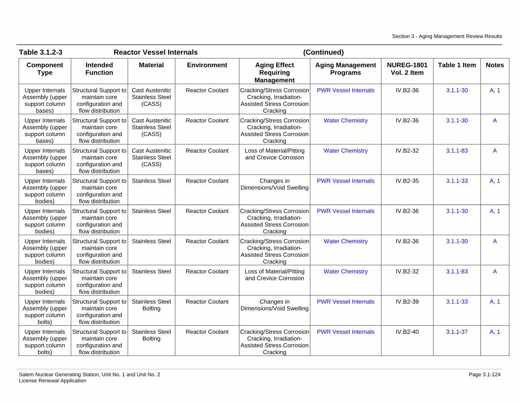
Section 3 - Aging Management Review Results
Salem Nuclear Generating Station, Unit No. 1 and Unit No. 2 Page 3.1-124 License Renewal Application
Table 3.1.2-3 Reactor Vessel Internals (Continued)
Component Type
Intended Function
Material Environment Aging Effect Requiring
Management
Aging Management Programs
NUREG-1801 Vol. 2 Item
Table 1 Item Notes
Upper Internals Assembly (upper support column
bases)
Structural Support to maintain core
configuration and flow distribution
Cast Austenitic Stainless Steel
(CASS)
Reactor Coolant Cracking/Stress Corrosion Cracking, Irradiation-
Assisted Stress Corrosion Cracking
PWR Vessel Internals IV.B2-36 3.1.1-30 A, 1
Upper Internals Assembly (upper support column
bases)
Structural Support to maintain core
configuration and flow distribution
Cast Austenitic Stainless Steel
(CASS)
Reactor Coolant Cracking/Stress Corrosion Cracking, Irradiation-
Assisted Stress Corrosion Cracking
Water Chemistry IV.B2-36 3.1.1-30 A
Upper Internals Assembly (upper support column
bases)
Structural Support to maintain core
configuration and flow distribution
Cast Austenitic Stainless Steel
(CASS)
Reactor Coolant Loss of Material/Pitting and Crevice Corrosion
Water Chemistry IV.B2-32 3.1.1-83 A
Upper Internals Assembly (upper support column
bodies)
Structural Support to maintain core
configuration and flow distribution
Stainless Steel Reactor Coolant Changes in Dimensions/Void Swelling
PWR Vessel Internals IV.B2-35 3.1.1-33 A, 1
Upper Internals Assembly (upper support column
bodies)
Structural Support to maintain core
configuration and flow distribution
Stainless Steel Reactor Coolant Cracking/Stress Corrosion Cracking, Irradiation-
Assisted Stress Corrosion Cracking
PWR Vessel Internals IV.B2-36 3.1.1-30 A, 1
Upper Internals Assembly (upper support column
bodies)
Structural Support to maintain core
configuration and flow distribution
Stainless Steel Reactor Coolant Cracking/Stress Corrosion Cracking, Irradiation-
Assisted Stress Corrosion Cracking
Water Chemistry IV.B2-36 3.1.1-30 A
Upper Internals Assembly (upper support column
bodies)
Structural Support to maintain core
configuration and flow distribution
Stainless Steel Reactor Coolant Loss of Material/Pitting and Crevice Corrosion
Water Chemistry IV.B2-32 3.1.1-83 A
Upper Internals Assembly (upper support column
bolts)
Structural Support to maintain core
configuration and flow distribution
Stainless Steel Bolting
Reactor Coolant Changes in Dimensions/Void Swelling
PWR Vessel Internals IV.B2-39 3.1.1-33 A, 1
Upper Internals Assembly (upper support column
bolts)
Structural Support to maintain core
configuration and flow distribution
Stainless Steel Bolting
Reactor Coolant Cracking/Stress Corrosion Cracking, Irradiation-
Assisted Stress Corrosion Cracking
PWR Vessel Internals IV.B2-40 3.1.1-37 A, 1

Section 3 - Aging Management Review Results
Salem Nuclear Generating Station, Unit No. 1 and Unit No. 2 Page 3.1-125 License Renewal Application
Table 3.1.2-3 Reactor Vessel Internals (Continued)
Component Type
Intended Function
Material Environment Aging Effect Requiring
Management
Aging Management Programs
NUREG-1801 Vol. 2 Item
Table 1 Item Notes
Upper Internals Assembly (upper support column
bolts)
Structural Support to maintain core
configuration and flow distribution
Stainless Steel Bolting
Reactor Coolant Cracking/Stress Corrosion Cracking, Irradiation-
Assisted Stress Corrosion Cracking
Water Chemistry IV.B2-40 3.1.1-37 A
Upper Internals Assembly (upper support column
bolts)
Structural Support to maintain core
configuration and flow distribution
Stainless Steel Bolting
Reactor Coolant Loss of Material/Pitting and Crevice Corrosion
Water Chemistry IV.B2-32 3.1.1-83 A
Upper Internals Assembly (upper support column
bolts)
Structural Support to maintain core
configuration and flow distribution
Stainless Steel Bolting
Reactor Coolant Loss of Preload/Stress Relaxation
PWR Vessel Internals IV.B2-38 3.1.1-27 A, 1
Upper Internals Assembly (upper support column extension tubes and adapters)
Structural Support to maintain core
configuration and flow distribution
Stainless Steel Reactor Coolant Changes in Dimensions/Void Swelling
PWR Vessel Internals IV.B2-35 3.1.1-33 A, 1
Upper Internals Assembly (upper support column extension tubes and adapters)
Structural Support to maintain core
configuration and flow distribution
Stainless Steel Reactor Coolant Cracking/Stress Corrosion Cracking, Irradiation-
Assisted Stress Corrosion Cracking
PWR Vessel Internals IV.B2-36 3.1.1-30 A, 1
Upper Internals Assembly (upper support column extension tubes and adapters)
Structural Support to maintain core
configuration and flow distribution
Stainless Steel Reactor Coolant Cracking/Stress Corrosion Cracking, Irradiation-
Assisted Stress Corrosion Cracking
Water Chemistry IV.B2-36 3.1.1-30 A
Upper Internals Assembly (upper support column extension tubes and adapters)
Structural Support to maintain core
configuration and flow distribution
Stainless Steel Reactor Coolant Loss of Material/Pitting and Crevice Corrosion
Water Chemistry IV.B2-32 3.1.1-83 A
Upper Internals Assembly (upper support column
flanges)
Structural Support to maintain core
configuration and flow distribution
Stainless Steel Reactor Coolant Changes in Dimensions/Void Swelling
PWR Vessel Internals IV.B2-35 3.1.1-33 A, 1

Section 3 - Aging Management Review Results
Salem Nuclear Generating Station, Unit No. 1 and Unit No. 2 Page 3.1-126 License Renewal Application
Table 3.1.2-3 Reactor Vessel Internals (Continued)
Component Type
Intended Function
Material Environment Aging Effect Requiring
Management
Aging Management Programs
NUREG-1801 Vol. 2 Item
Table 1 Item Notes
Upper Internals Assembly (upper support column
flanges)
Structural Support to maintain core
configuration and flow distribution
Stainless Steel Reactor Coolant Cracking/Stress Corrosion Cracking, Irradiation-
Assisted Stress Corrosion Cracking
PWR Vessel Internals IV.B2-36 3.1.1-30 A, 1
Upper Internals Assembly (upper support column
flanges)
Structural Support to maintain core
configuration and flow distribution
Stainless Steel Reactor Coolant Cracking/Stress Corrosion Cracking, Irradiation-
Assisted Stress Corrosion Cracking
Water Chemistry IV.B2-36 3.1.1-30 A
Upper Internals Assembly (upper support column
flanges)
Structural Support to maintain core
configuration and flow distribution
Stainless Steel Reactor Coolant Loss of Material/Pitting and Crevice Corrosion
Water Chemistry IV.B2-32 3.1.1-83 A
Upper Internals Assembly (upper support column
lock keys)
Structural Support to maintain core
configuration and flow distribution
Stainless Steel Reactor Coolant Changes in Dimensions/Void Swelling
PWR Vessel Internals IV.B2-35 3.1.1-33 A, 1
Upper Internals Assembly (upper support column
lock keys)
Structural Support to maintain core
configuration and flow distribution
Stainless Steel Reactor Coolant Cracking/Stress Corrosion Cracking, Irradiation-
Assisted Stress Corrosion Cracking
PWR Vessel Internals IV.B2-36 3.1.1-30 A, 1
Upper Internals Assembly (upper support column
lock keys)
Structural Support to maintain core
configuration and flow distribution
Stainless Steel Reactor Coolant Cracking/Stress Corrosion Cracking, Irradiation-
Assisted Stress Corrosion Cracking
Water Chemistry IV.B2-36 3.1.1-30 A
Upper Internals Assembly (upper support column
lock keys)
Structural Support to maintain core
configuration and flow distribution
Stainless Steel Reactor Coolant Loss of Material/Pitting and Crevice Corrosion
Water Chemistry IV.B2-32 3.1.1-83 A
Upper Internals Assembly (upper support column
lock keys)
Structural Support to maintain core
configuration and flow distribution
Stainless Steel Reactor Coolant Loss of Material/Wear ASME Section XI Inservice Inspection,
Subsections IWB, IWC, and IWD
IV.B2-26 3.1.1-63 C
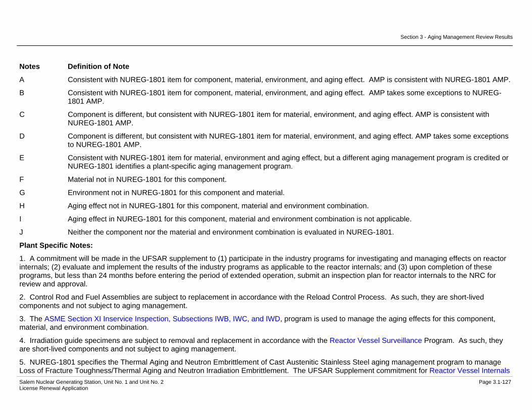
Section 3 - Aging Management Review Results
Salem Nuclear Generating Station, Unit No. 1 and Unit No. 2 Page 3.1-127 License Renewal Application
Notes Definition of Note
A Consistent with NUREG-1801 item for component, material, environment, and aging effect. AMP is consistent with NUREG-1801 AMP.
B Consistent with NUREG-1801 item for component, material, environment, and aging effect. AMP takes some exceptions to NUREG-1801 AMP.
C Component is different, but consistent with NUREG-1801 item for material, environment, and aging effect. AMP is consistent with NUREG-1801 AMP.
D Component is different, but consistent with NUREG-1801 item for material, environment, and aging effect. AMP takes some exceptions to NUREG-1801 AMP.
E Consistent with NUREG-1801 item for material, environment and aging effect, but a different aging management program is credited or NUREG-1801 identifies a plant-specific aging management program.
F Material not in NUREG-1801 for this component.
G Environment not in NUREG-1801 for this component and material.
H Aging effect not in NUREG-1801 for this component, material and environment combination.
I Aging effect in NUREG-1801 for this component, material and environment combination is not applicable.
J Neither the component nor the material and environment combination is evaluated in NUREG-1801.
Plant Specific Notes:
1. A commitment will be made in the UFSAR supplement to (1) participate in the industry programs for investigating and managing effects on reactor internals; (2) evaluate and implement the results of the industry programs as applicable to the reactor internals; and (3) upon completion of these programs, but less than 24 months before entering the period of extended operation, submit an inspection plan for reactor internals to the NRC for review and approval.
2. Control Rod and Fuel Assemblies are subject to replacement in accordance with the Reload Control Process. As such, they are short-lived components and not subject to aging management.
3. The ASME Section XI Inservice Inspection, Subsections IWB, IWC, and IWD, program is used to manage the aging effects for this component, material, and environment combination.
4. Irradiation guide specimens are subject to removal and replacement in accordance with the Reactor Vessel Surveillance Program. As such, they are short-lived components and not subject to aging management.
5. NUREG-1801 specifies the Thermal Aging and Neutron Embrittlement of Cast Austenitic Stainless Steel aging management program to manage Loss of Fracture Toughness/Thermal Aging and Neutron Irradiation Embrittlement. The UFSAR Supplement commitment for Reactor Vessel Internals

Section 3 - Aging Management Review Results
Salem Nuclear Generating Station, Unit No. 1 and Unit No. 2 Page 3.1-128 License Renewal Application
(see Note 1) will be used to manage Loss of Fracture Toughness/Thermal Aging and Neutron Irradiation Embrittlement for the cast austenitic stainless steel vessel internals.
6. The TLAA designation in the Aging Management Program column indicates fatigue of this component is evaluated in Section 4.3.

Section 3 - Aging Management Review Results
Salem Nuclear Generating Station, Unit No. 1 and Unit No. 2 Page 3.1-129 License Renewal Application
Table 3.1.2-4 Steam Generators
Summary of Aging Management Evaluation
Table 3.1.2-4 Steam Generators
Component Type
Intended Function
Material Environment Aging Effect Requiring
Management
Aging Management Programs
NUREG-1801 Vol. 2 Item
Table 1 Item Notes
Bolting Mechanical Closure Carbon and Low Alloy Steel
Bolting
Air - Indoor (External) Cumulative Fatigue Damage/Fatigue
TLAA IV.C2-10 3.1.1-7 A, 1
Bolting Mechanical Closure Carbon and Low Alloy Steel
Bolting
Air - Indoor (External) Loss of Material/General, Pitting and Crevice
Corrosion
Bolting Integrity V.E-4 3.2.1-23 B
Bolting Mechanical Closure Carbon and Low Alloy Steel
Bolting
Air - Indoor (External) Loss of Preload/Thermal Effects, Gasket Creep,
and Self-Loosening
Bolting Integrity IV.C2-8 3.1.1-52 B
Bolting Mechanical Closure Carbon and Low Alloy Steel
Bolting
Air with Borated Water Leakage (External)
Loss of Material/Boric Acid Corrosion
Boric Acid Corrosion IV.C2-9 3.1.1-58 A
Flow Element Leakage Boundary Carbon Steel Air - Indoor (External) Loss of Material/General Corrosion
External Surfaces Monitoring
VIII.H-7 3.4.1-28 A
Flow Element Leakage Boundary Carbon Steel Air with Borated Water Leakage (External)
Loss of Material/Boric Acid Corrosion
Boric Acid Corrosion VIII.H-9 3.4.1-38 A
Flow Element Leakage Boundary Carbon Steel Treated Water (Internal) Loss of Material/General, Pitting and Crevice
Corrosion
One-Time Inspection VIII.F-25 3.4.1-4 A
Flow Element Leakage Boundary Carbon Steel Treated Water (Internal) Loss of Material/General, Pitting and Crevice
Corrosion
Water Chemistry VIII.F-25 3.4.1-4 A
Piping and Fittings Leakage Boundary Carbon Steel Air - Indoor (External) Loss of Material/General Corrosion
External Surfaces Monitoring
VIII.H-7 3.4.1-28 A
Piping and Fittings Leakage Boundary Carbon Steel Air with Borated Water Leakage (External)
Loss of Material/Boric Acid Corrosion
Boric Acid Corrosion VIII.H-9 3.4.1-38 A
Piping and Fittings Leakage Boundary Carbon Steel Treated Water (Internal) Cumulative Fatigue Damage/Fatigue
TLAA IV.D1-11 3.1.1-7 A, 1
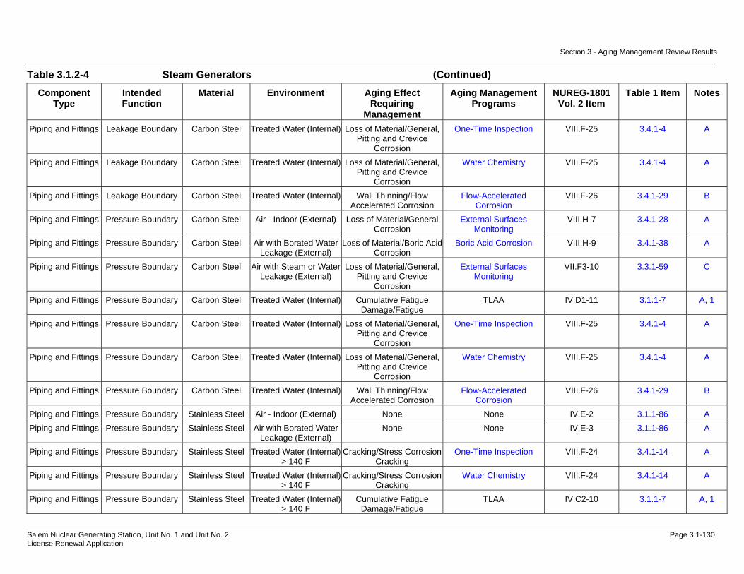
Section 3 - Aging Management Review Results
Salem Nuclear Generating Station, Unit No. 1 and Unit No. 2 Page 3.1-130 License Renewal Application
Table 3.1.2-4 Steam Generators (Continued)
Component Type
Intended Function
Material Environment Aging Effect Requiring
Management
Aging Management Programs
NUREG-1801 Vol. 2 Item
Table 1 Item Notes
Piping and Fittings Leakage Boundary Carbon Steel Treated Water (Internal) Loss of Material/General, Pitting and Crevice
Corrosion
One-Time Inspection VIII.F-25 3.4.1-4 A
Piping and Fittings Leakage Boundary Carbon Steel Treated Water (Internal) Loss of Material/General, Pitting and Crevice
Corrosion
Water Chemistry VIII.F-25 3.4.1-4 A
Piping and Fittings Leakage Boundary Carbon Steel Treated Water (Internal) Wall Thinning/Flow Accelerated Corrosion
Flow-Accelerated Corrosion
VIII.F-26 3.4.1-29 B
Piping and Fittings Pressure Boundary Carbon Steel Air - Indoor (External) Loss of Material/General Corrosion
External Surfaces Monitoring
VIII.H-7 3.4.1-28 A
Piping and Fittings Pressure Boundary Carbon Steel Air with Borated Water Leakage (External)
Loss of Material/Boric Acid Corrosion
Boric Acid Corrosion VIII.H-9 3.4.1-38 A
Piping and Fittings Pressure Boundary Carbon Steel Air with Steam or Water Leakage (External)
Loss of Material/General, Pitting and Crevice
Corrosion
External Surfaces Monitoring
VII.F3-10 3.3.1-59 C
Piping and Fittings Pressure Boundary Carbon Steel Treated Water (Internal) Cumulative Fatigue Damage/Fatigue
TLAA IV.D1-11 3.1.1-7 A, 1
Piping and Fittings Pressure Boundary Carbon Steel Treated Water (Internal) Loss of Material/General, Pitting and Crevice
Corrosion
One-Time Inspection VIII.F-25 3.4.1-4 A
Piping and Fittings Pressure Boundary Carbon Steel Treated Water (Internal) Loss of Material/General, Pitting and Crevice
Corrosion
Water Chemistry VIII.F-25 3.4.1-4 A
Piping and Fittings Pressure Boundary Carbon Steel Treated Water (Internal) Wall Thinning/Flow Accelerated Corrosion
Flow-Accelerated Corrosion
VIII.F-26 3.4.1-29 B
Piping and Fittings Pressure Boundary Stainless Steel Air - Indoor (External) None None IV.E-2 3.1.1-86 A Piping and Fittings Pressure Boundary Stainless Steel Air with Borated Water
Leakage (External) None None IV.E-3 3.1.1-86 A
Piping and Fittings Pressure Boundary Stainless Steel Treated Water (Internal) > 140 F
Cracking/Stress Corrosion Cracking
One-Time Inspection VIII.F-24 3.4.1-14 A
Piping and Fittings Pressure Boundary Stainless Steel Treated Water (Internal) > 140 F
Cracking/Stress Corrosion Cracking
Water Chemistry VIII.F-24 3.4.1-14 A
Piping and Fittings Pressure Boundary Stainless Steel Treated Water (Internal) > 140 F
Cumulative Fatigue Damage/Fatigue
TLAA IV.C2-10 3.1.1-7 A, 1

Section 3 - Aging Management Review Results
Salem Nuclear Generating Station, Unit No. 1 and Unit No. 2 Page 3.1-131 License Renewal Application
Table 3.1.2-4 Steam Generators (Continued)
Component Type
Intended Function
Material Environment Aging Effect Requiring
Management
Aging Management Programs
NUREG-1801 Vol. 2 Item
Table 1 Item Notes
Piping and Fittings Pressure Boundary Stainless Steel Treated Water (Internal) > 140 F
Loss of Material/Pitting and Crevice Corrosion
One-Time Inspection VIII.F-23 3.4.1-16 A
Piping and Fittings Pressure Boundary Stainless Steel Treated Water (Internal) > 140 F
Loss of Material/Pitting and Crevice Corrosion
Water Chemistry VIII.F-23 3.4.1-16 A
Pump Casing (Steam Generator
Blowdown Analyzer Drain Pumps)
Leakage Boundary Carbon Steel Air - Indoor (External) Loss of Material/General Corrosion
External Surfaces Monitoring
VIII.H-7 3.4.1-28 A
Pump Casing (Steam Generator
Blowdown Analyzer Drain Pumps)
Leakage Boundary Carbon Steel Air with Borated Water Leakage (External)
Loss of Material/Boric Acid Corrosion
Boric Acid Corrosion VIII.H-9 3.4.1-38 A
Pump Casing (Steam Generator
Blowdown Analyzer Drain Pumps)
Leakage Boundary Carbon Steel Treated Water (Internal) Loss of Material/General, Pitting and Crevice
Corrosion
One-Time Inspection VIII.E-40 3.4.1-6 C
Pump Casing (Steam Generator
Blowdown Analyzer Drain Pumps)
Leakage Boundary Carbon Steel Treated Water (Internal) Loss of Material/General, Pitting and Crevice
Corrosion
Water Chemistry VIII.E-40 3.4.1-6 C
Spray Nozzles Direct Flow Nickel Alloy Treated Water (Internal) Loss of Material/Pitting and Crevice Corrosion
One-Time Inspection H, 2
Spray Nozzles Direct Flow Nickel Alloy Treated Water (Internal) Loss of Material/Pitting and Crevice Corrosion
Water Chemistry H, 2
Steam Generators (Feedwater Ring
and Support)
Direct Flow Carbon Steel Treated Water (Internal) Loss of Material/General, Pitting and Crevice
Corrosion
Steam Generator Tube Integrity
IV.D1-12 3.1.1-16 E, 3
Steam Generators (Feedwater Ring
and Support)
Direct Flow Carbon Steel Treated Water (Internal) Loss of Material/General, Pitting and Crevice
Corrosion
Water Chemistry IV.D1-12 3.1.1-16 A
Steam Generators (Feedwater Ring
and Support)
Direct Flow Carbon Steel Treated Water (Internal) Wall Thinning/Flow Accelerated Corrosion
Steam Generator Tube Integrity
IV.D1-26 3.1.1-32 E, 3
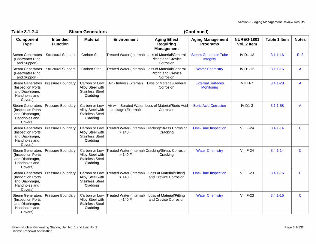
Section 3 - Aging Management Review Results
Salem Nuclear Generating Station, Unit No. 1 and Unit No. 2 Page 3.1-132 License Renewal Application
Table 3.1.2-4 Steam Generators (Continued)
Component Type
Intended Function
Material Environment Aging Effect Requiring
Management
Aging Management Programs
NUREG-1801 Vol. 2 Item
Table 1 Item Notes
Steam Generators (Feedwater Ring
and Support)
Structural Support Carbon Steel Treated Water (Internal) Loss of Material/General, Pitting and Crevice
Corrosion
Steam Generator Tube Integrity
IV.D1-12 3.1.1-16 E, 3
Steam Generators (Feedwater Ring
and Support)
Structural Support Carbon Steel Treated Water (Internal) Loss of Material/General, Pitting and Crevice
Corrosion
Water Chemistry IV.D1-12 3.1.1-16 A
Steam Generators (Inspection Ports and Diaphragm, Handholes and
Covers)
Pressure Boundary Carbon or Low Alloy Steel with Stainless Steel
Cladding
Air - Indoor (External) Loss of Material/General Corrosion
External Surfaces Monitoring
VIII.H-7 3.4.1-28 A
Steam Generators (Inspection Ports and Diaphragm, Handholes and
Covers)
Pressure Boundary Carbon or Low Alloy Steel with Stainless Steel
Cladding
Air with Borated Water Leakage (External)
Loss of Material/Boric Acid Corrosion
Boric Acid Corrosion IV.D1-3 3.1.1-58 A
Steam Generators (Inspection Ports and Diaphragm, Handholes and
Covers)
Pressure Boundary Carbon or Low Alloy Steel with Stainless Steel
Cladding
Treated Water (Internal) > 140 F
Cracking/Stress Corrosion Cracking
One-Time Inspection VIII.F-24 3.4.1-14 C
Steam Generators (Inspection Ports and Diaphragm, Handholes and
Covers)
Pressure Boundary Carbon or Low Alloy Steel with Stainless Steel
Cladding
Treated Water (Internal) > 140 F
Cracking/Stress Corrosion Cracking
Water Chemistry VIII.F-24 3.4.1-14 C
Steam Generators (Inspection Ports and Diaphragm, Handholes and
Covers)
Pressure Boundary Carbon or Low Alloy Steel with Stainless Steel
Cladding
Treated Water (Internal) > 140 F
Loss of Material/Pitting and Crevice Corrosion
One-Time Inspection VIII.F-23 3.4.1-16 C
Steam Generators (Inspection Ports and Diaphragm, Handholes and
Covers)
Pressure Boundary Carbon or Low Alloy Steel with Stainless Steel
Cladding
Treated Water (Internal) > 140 F
Loss of Material/Pitting and Crevice Corrosion
Water Chemistry VIII.F-23 3.4.1-16 C

Section 3 - Aging Management Review Results
Salem Nuclear Generating Station, Unit No. 1 and Unit No. 2 Page 3.1-133 License Renewal Application
Table 3.1.2-4 Steam Generators (Continued)
Component Type
Intended Function
Material Environment Aging Effect Requiring
Management
Aging Management Programs
NUREG-1801 Vol. 2 Item
Table 1 Item Notes
Steam Generators (Inspection Ports and Diaphragm, Handholes and
Covers)
Pressure Boundary Stainless Steel (Unit 2 only)
Air - Indoor (External) None None IV.E-2 3.1.1-86 A
Steam Generators (Inspection Ports and Diaphragm, Handholes and
Covers)
Pressure Boundary Stainless Steel (Unit 2 only)
Air with Borated Water Leakage (External)
None None IV.E-3 3.1.1-86 C
Steam Generators (Inspection Ports and Diaphragm, Handholes and
Covers)
Pressure Boundary Stainless Steel (Unit 2 only)
Treated Water (Internal) > 140 F
Cracking/Stress Corrosion Cracking
One-Time Inspection VIII.F-24 3.4.1-14 C
Steam Generators (Inspection Ports and Diaphragm, Handholes and
Covers)
Pressure Boundary Stainless Steel (Unit 2 only)
Treated Water (Internal) > 140 F
Cracking/Stress Corrosion Cracking
Water Chemistry VIII.F-24 3.4.1-14 C
Steam Generators (Inspection Ports and Diaphragm, Handholes and
Covers)
Pressure Boundary Stainless Steel (Unit 2 only)
Treated Water (Internal) > 140 F
Loss of Material/Pitting and Crevice Corrosion
One-Time Inspection VIII.F-23 3.4.1-16 C
Steam Generators (Inspection Ports and Diaphragm, Handholes and
Covers)
Pressure Boundary Stainless Steel (Unit 2 only)
Treated Water (Internal) > 140 F
Loss of Material/Pitting and Crevice Corrosion
Water Chemistry VIII.F-23 3.4.1-16 C
Steam Generators (Level Sensing,
Sampling, Wet Lay-Up, and Drain Connections)
Pressure Boundary Low Alloy Steel Air - Indoor (External) Loss of Material/General Corrosion
External Surfaces Monitoring
VIII.H-7 3.4.1-28 A
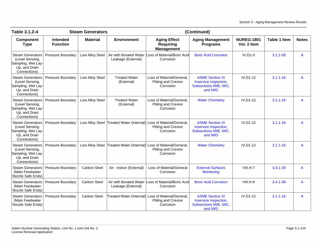
Section 3 - Aging Management Review Results
Salem Nuclear Generating Station, Unit No. 1 and Unit No. 2 Page 3.1-134 License Renewal Application
Table 3.1.2-4 Steam Generators (Continued)
Component Type
Intended Function
Material Environment Aging Effect Requiring
Management
Aging Management Programs
NUREG-1801 Vol. 2 Item
Table 1 Item Notes
Steam Generators (Level Sensing,
Sampling, Wet Lay-Up, and Drain Connections)
Pressure Boundary Low Alloy Steel Air with Borated Water Leakage (External)
Loss of Material/Boric Acid Corrosion
Boric Acid Corrosion IV.D1-3 3.1.1-58 A
Steam Generators (Level Sensing,
Sampling, Wet Lay-Up, and Drain Connections)
Pressure Boundary Low Alloy Steel Treated Water (External)
Loss of Material/General, Pitting and Crevice
Corrosion
ASME Section XI Inservice Inspection,
Subsections IWB, IWC, and IWD
IV.D1-12 3.1.1-16 A
Steam Generators (Level Sensing,
Sampling, Wet Lay-Up, and Drain Connections)
Pressure Boundary Low Alloy Steel Treated Water (External)
Loss of Material/General, Pitting and Crevice
Corrosion
Water Chemistry IV.D1-12 3.1.1-16 A
Steam Generators (Level Sensing,
Sampling, Wet Lay-Up, and Drain Connections)
Pressure Boundary Low Alloy Steel Treated Water (Internal) Loss of Material/General, Pitting and Crevice
Corrosion
ASME Section XI Inservice Inspection,
Subsections IWB, IWC, and IWD
IV.D1-12 3.1.1-16 A
Steam Generators (Level Sensing,
Sampling, Wet Lay-Up, and Drain Connections)
Pressure Boundary Low Alloy Steel Treated Water (Internal) Loss of Material/General, Pitting and Crevice
Corrosion
Water Chemistry IV.D1-12 3.1.1-16 A
Steam Generators (Main Feedwater
Nozzle Safe Ends)
Pressure Boundary Carbon Steel Air - Indoor (External) Loss of Material/General Corrosion
External Surfaces Monitoring
VIII.H-7 3.4.1-28 A
Steam Generators (Main Feedwater
Nozzle Safe Ends)
Pressure Boundary Carbon Steel Air with Borated Water Leakage (External)
Loss of Material/Boric Acid Corrosion
Boric Acid Corrosion VIII.H-9 3.4.1-38 A
Steam Generators (Main Feedwater
Nozzle Safe Ends)
Pressure Boundary Carbon Steel Treated Water (Internal) Loss of Material/General, Pitting and Crevice
Corrosion
ASME Section XI Inservice Inspection,
Subsections IWB, IWC, and IWD
IV.D1-12 3.1.1-16 A

Section 3 - Aging Management Review Results
Salem Nuclear Generating Station, Unit No. 1 and Unit No. 2 Page 3.1-135 License Renewal Application
Table 3.1.2-4 Steam Generators (Continued)
Component Type
Intended Function
Material Environment Aging Effect Requiring
Management
Aging Management Programs
NUREG-1801 Vol. 2 Item
Table 1 Item Notes
Steam Generators (Main Feedwater
Nozzle Safe Ends)
Pressure Boundary Carbon Steel Treated Water (Internal) Loss of Material/General, Pitting and Crevice
Corrosion
Water Chemistry IV.D1-12 3.1.1-16 A
Steam Generators (Main Feedwater
Nozzle Safe Ends)
Pressure Boundary Carbon Steel Treated Water (Internal) Wall Thinning/Flow Accelerated Corrosion
Flow-Accelerated Corrosion
IV.D1-5 3.1.1-59 B
Steam Generators (Main Feedwater
Nozzles)
Pressure Boundary Low Alloy Steel Air - Indoor (External) Loss of Material/General Corrosion
External Surfaces Monitoring
VIII.H-7 3.4.1-28 A
Steam Generators (Main Feedwater
Nozzles)
Pressure Boundary Low Alloy Steel Air with Borated Water Leakage (External)
Loss of Material/Boric Acid Corrosion
Boric Acid Corrosion IV.D1-3 3.1.1-58 A
Steam Generators (Main Feedwater
Nozzles)
Pressure Boundary Low Alloy Steel Treated Water (Internal) Cumulative Fatigue Damage/Fatigue
TLAA IV.D1-11 3.1.1-7 A, 1
Steam Generators (Main Feedwater
Nozzles)
Pressure Boundary Low Alloy Steel Treated Water (Internal) Loss of Material/General, Pitting and Crevice
Corrosion
ASME Section XI Inservice Inspection,
Subsections IWB, IWC, and IWD
IV.D1-12 3.1.1-16 A
Steam Generators (Main Feedwater
Nozzles)
Pressure Boundary Low Alloy Steel Treated Water (Internal) Loss of Material/General, Pitting and Crevice
Corrosion
Water Chemistry IV.D1-12 3.1.1-16 A
Steam Generators (Main Feedwater
Nozzles)
Pressure Boundary Low Alloy Steel Treated Water (Internal) Wall Thinning/Flow Accelerated Corrosion
Flow-Accelerated Corrosion
IV.D1-5 3.1.1-59 B
Steam Generators (Main Steam
Nozzle)
Pressure Boundary Low Alloy Steel Air - Indoor (External) Loss of Material/General Corrosion
External Surfaces Monitoring
VIII.H-7 3.4.1-28 A
Steam Generators (Main Steam
Nozzle)
Pressure Boundary Low Alloy Steel Air with Borated Water Leakage (External)
Loss of Material/Boric Acid Corrosion
Boric Acid Corrosion IV.D1-3 3.1.1-58 A
Steam Generators (Main Steam
Nozzle)
Pressure Boundary Low Alloy Steel Steam (Internal) Cumulative Fatigue Damage/Fatigue
TLAA IV.D1-11 3.1.1-7 A, 1

Section 3 - Aging Management Review Results
Salem Nuclear Generating Station, Unit No. 1 and Unit No. 2 Page 3.1-136 License Renewal Application
Table 3.1.2-4 Steam Generators (Continued)
Component Type
Intended Function
Material Environment Aging Effect Requiring
Management
Aging Management Programs
NUREG-1801 Vol. 2 Item
Table 1 Item Notes
Steam Generators (Main Steam
Nozzle)
Pressure Boundary Low Alloy Steel Steam (Internal) Loss of Material/General, Pitting and Crevice
Corrosion
ASME Section XI Inservice Inspection,
Subsections IWB, IWC, and IWD
IV.D1-12 3.1.1-16 A
Steam Generators (Main Steam
Nozzle)
Pressure Boundary Low Alloy Steel Steam (Internal) Loss of Material/General, Pitting and Crevice
Corrosion
Water Chemistry IV.D1-12 3.1.1-16 A
Steam Generators (Main Steam
Nozzle)
Pressure Boundary Low Alloy Steel Steam (Internal) Wall Thinning/Flow Accelerated Corrosion
Flow-Accelerated Corrosion
IV.D1-5 3.1.1-59 B
Steam Generators (Primary Channel
Head Divider Plate)
Direct Flow Nickel Alloy Reactor Coolant (External)
Cracking/Stress Corrosion Cracking
Water Chemistry IV.D1-6 3.1.1-81 A
Steam Generators (Primary Channel
Head Divider Plate)
Direct Flow Nickel Alloy Reactor Coolant (External)
Loss of Material/Pitting and Crevice Corrosion
Water Chemistry IV.C2-15 3.1.1-83 C
Steam Generators (Primary Channel Head Drain, Plug, and Welds - Unit 1
only)
Pressure Boundary Nickel Alloy Air - Indoor (External) None None IV.E-1 3.1.1-85 A
Steam Generators (Primary Channel Head Drain, Plug, and Welds - Unit 1
only)
Pressure Boundary Nickel Alloy Air with Borated Water Leakage (External)
None None G, 4
Steam Generators (Primary Channel Head Drain, Plug, and Welds - Unit 1
only)
Pressure Boundary Nickel Alloy Reactor Coolant (Internal)
Cracking/Stress Corrosion Cracking
ASME Section XI Inservice Inspection,
Subsections IWB, IWC, and IWD
IV.D1-4 3.1.1-31 A
Steam Generators (Primary Channel Head Drain, Plug, and Welds - Unit 1
only)
Pressure Boundary Nickel Alloy Reactor Coolant (Internal)
Cracking/Stress Corrosion Cracking
Nickel Alloy Aging Management Program
IV.D1-4 3.1.1-31 A

Section 3 - Aging Management Review Results
Salem Nuclear Generating Station, Unit No. 1 and Unit No. 2 Page 3.1-137 License Renewal Application
Table 3.1.2-4 Steam Generators (Continued)
Component Type
Intended Function
Material Environment Aging Effect Requiring
Management
Aging Management Programs
NUREG-1801 Vol. 2 Item
Table 1 Item Notes
Steam Generators (Primary Channel Head Drain, Plug, and Welds - Unit 1
only)
Pressure Boundary Nickel Alloy Reactor Coolant (Internal)
Cracking/Stress Corrosion Cracking
Water Chemistry IV.D1-4 3.1.1-31 A
Steam Generators (Primary Channel Head Drain, Plug, and Welds - Unit 1
only)
Pressure Boundary Nickel Alloy Reactor Coolant (Internal)
Loss of Material/Pitting and Crevice Corrosion
Water Chemistry IV.C2-15 3.1.1-83 C
Steam Generators (Primary Channel Head Drain, Plug, and Welds - Unit 1
only)
Pressure Boundary Stainless Steel Air - Indoor (External) None None IV.E-2 3.1.1-86 A
Steam Generators (Primary Channel Head Drain, Plug, and Welds - Unit 1
only)
Pressure Boundary Stainless Steel Air with Borated Water Leakage (External)
None None IV.E-3 3.1.1-86 C
Steam Generators (Primary Channel Head Drain, Plug, and Welds - Unit 1
only)
Pressure Boundary Stainless Steel Reactor Coolant (Internal)
Cracking/Stress Corrosion Cracking
ASME Section XI Inservice Inspection,
Subsections IWB, IWC, and IWD
IV.D1-1 3.1.1-68 C
Steam Generators (Primary Channel Head Drain, Plug, and Welds - Unit 1
only)
Pressure Boundary Stainless Steel Reactor Coolant (Internal)
Cracking/Stress Corrosion Cracking
Water Chemistry IV.D1-1 3.1.1-68 C
Steam Generators (Primary Channel Head Drain, Plug, and Welds - Unit 1
only)
Pressure Boundary Stainless Steel Reactor Coolant (Internal)
Loss of Material/Pitting and Crevice Corrosion
Water Chemistry IV.C2-15 3.1.1-83 C

Section 3 - Aging Management Review Results
Salem Nuclear Generating Station, Unit No. 1 and Unit No. 2 Page 3.1-138 License Renewal Application
Table 3.1.2-4 Steam Generators (Continued)
Component Type
Intended Function
Material Environment Aging Effect Requiring
Management
Aging Management Programs
NUREG-1801 Vol. 2 Item
Table 1 Item Notes
Steam Generators (Primary Channel
Head, Nozzles, and Manways)
Pressure Boundary Carbon or Low Alloy Steel with Stainless Steel
Cladding
Air - Indoor (External) Loss of Material/General Corrosion
External Surfaces Monitoring
VIII.H-7 3.4.1-28 A
Steam Generators (Primary Channel
Head, Nozzles, and Manways)
Pressure Boundary Carbon or Low Alloy Steel with Stainless Steel
Cladding
Air with Borated Water Leakage (External)
Loss of Material/Boric Acid Corrosion
Boric Acid Corrosion IV.D1-3 3.1.1-58 A
Steam Generators (Primary Channel
Head, Nozzles, and Manways)
Pressure Boundary Carbon or Low Alloy Steel with Stainless Steel
Cladding
Reactor Coolant (Internal)
Cracking/Stress Corrosion Cracking
ASME Section XI Inservice Inspection,
Subsections IWB, IWC, and IWD
IV.D1-1 3.1.1-68 A
Steam Generators (Primary Channel
Head, Nozzles, and Manways)
Pressure Boundary Carbon or Low Alloy Steel with Stainless Steel
Cladding
Reactor Coolant (Internal)
Cracking/Stress Corrosion Cracking
Water Chemistry IV.D1-1 3.1.1-68 A
Steam Generators (Primary Channel
Head, Nozzles, and Manways)
Pressure Boundary Carbon or Low Alloy Steel with Stainless Steel
Cladding
Reactor Coolant (Internal)
Cumulative Fatigue Damage/Fatigue
TLAA IV.D1-8 3.1.1-10 A, 1
Steam Generators (Primary Channel
Head, Nozzles, and Manways)
Pressure Boundary Carbon or Low Alloy Steel with Stainless Steel
Cladding
Reactor Coolant (Internal)
Loss of Material/Pitting and Crevice Corrosion
Water Chemistry IV.C2-15 3.1.1-83 C
Steam Generators (Primary Manway
Cover Inserts - Unit 1 only)
Pressure Boundary Stainless Steel Air - Indoor (External) None None IV.E-2 3.1.1-86 C
Steam Generators (Primary Manway
Cover Inserts - Unit 1 only)
Pressure Boundary Stainless Steel Air with Borated Water Leakage (External)
None None IV.E-3 3.1.1-86 C
Steam Generators (Primary Manway
Cover Inserts - Unit 1 only)
Pressure Boundary Stainless Steel Reactor Coolant (Internal)
Cracking/Stress Corrosion Cracking
ASME Section XI Inservice Inspection,
Subsections IWB, IWC, and IWD
IV.D1-1 3.1.1-68 A

Section 3 - Aging Management Review Results
Salem Nuclear Generating Station, Unit No. 1 and Unit No. 2 Page 3.1-139 License Renewal Application
Table 3.1.2-4 Steam Generators (Continued)
Component Type
Intended Function
Material Environment Aging Effect Requiring
Management
Aging Management Programs
NUREG-1801 Vol. 2 Item
Table 1 Item Notes
Steam Generators (Primary Manway
Cover Inserts - Unit 1 only)
Pressure Boundary Stainless Steel Reactor Coolant (Internal)
Cracking/Stress Corrosion Cracking
Water Chemistry IV.D1-1 3.1.1-68 A
Steam Generators (Primary Manway
Cover Inserts - Unit 1 only)
Pressure Boundary Stainless Steel Reactor Coolant (Internal)
Loss of Material/Pitting and Crevice Corrosion
Water Chemistry IV.C2-15 3.1.1-83 C
Steam Generators (Primary Manway
Covers)
Pressure Boundary Carbon or Low Alloy Steel with Stainless Steel
Cladding
Air - Indoor (External) Loss of Material/General Corrosion
External Surfaces Monitoring
VIII.H-7 3.4.1-28 A
Steam Generators (Primary Manway
Covers)
Pressure Boundary Carbon or Low Alloy Steel with Stainless Steel
Cladding
Air with Borated Water Leakage (External)
Loss of Material/Boric Acid Corrosion
Boric Acid Corrosion IV.D1-3 3.1.1-58 A
Steam Generators (Primary Manway
Covers)
Pressure Boundary Carbon or Low Alloy Steel with Stainless Steel
Cladding
Reactor Coolant (Internal)
Cracking/Stress Corrosion Cracking
ASME Section XI Inservice Inspection,
Subsections IWB, IWC, and IWD
IV.D1-1 3.1.1-68 A
Steam Generators (Primary Manway
Covers)
Pressure Boundary Carbon or Low Alloy Steel with Stainless Steel
Cladding
Reactor Coolant (Internal)
Cracking/Stress Corrosion Cracking
Water Chemistry IV.D1-1 3.1.1-68 A
Steam Generators (Primary Manway
Covers)
Pressure Boundary Carbon or Low Alloy Steel with Stainless Steel
Cladding
Reactor Coolant (Internal)
Loss of Material/Pitting and Crevice Corrosion
Water Chemistry IV.C2-15 3.1.1-83 C
Steam Generators (Primary Nozzles
Safe Ends)
Pressure Boundary Stainless Steel Air - Indoor (External) None None IV.E-2 3.1.1-86 C
Steam Generators (Primary Nozzles
Safe Ends)
Pressure Boundary Stainless Steel Air with Borated Water Leakage (External)
None None IV.E-3 3.1.1-86 C

Section 3 - Aging Management Review Results
Salem Nuclear Generating Station, Unit No. 1 and Unit No. 2 Page 3.1-140 License Renewal Application
Table 3.1.2-4 Steam Generators (Continued)
Component Type
Intended Function
Material Environment Aging Effect Requiring
Management
Aging Management Programs
NUREG-1801 Vol. 2 Item
Table 1 Item Notes
Steam Generators (Primary Nozzles
Safe Ends)
Pressure Boundary Stainless Steel Reactor Coolant (Internal)
Cracking/Stress Corrosion Cracking
ASME Section XI Inservice Inspection,
Subsections IWB, IWC, and IWD
IV.D1-1 3.1.1-68 A
Steam Generators (Primary Nozzles
Safe Ends)
Pressure Boundary Stainless Steel Reactor Coolant (Internal)
Cracking/Stress Corrosion Cracking
Water Chemistry IV.D1-1 3.1.1-68 A
Steam Generators (Primary Nozzles
Safe Ends)
Pressure Boundary Stainless Steel Reactor Coolant (Internal)
Loss of Material/Pitting and Crevice Corrosion
Water Chemistry IV.C2-15 3.1.1-83 C
Steam Generators (Secondary
Manways and Covers)
Pressure Boundary Low Alloy Steel Air - Indoor (External) Loss of Material/General Corrosion
External Surfaces Monitoring
VIII.H-7 3.4.1-28 A
Steam Generators (Secondary
Manways and Covers)
Pressure Boundary Low Alloy Steel Air with Borated Water Leakage (External)
Loss of Material/Boric Acid Corrosion
Boric Acid Corrosion IV.D1-3 3.1.1-58 A
Steam Generators (Secondary
Manways and Covers)
Pressure Boundary Low Alloy Steel Treated Water (Internal) Loss of Material/General, Pitting and Crevice
Corrosion
ASME Section XI Inservice Inspection,
Subsections IWB, IWC, and IWD
IV.D1-12 3.1.1-16 A
Steam Generators (Secondary
Manways and Covers)
Pressure Boundary Low Alloy Steel Treated Water (Internal) Loss of Material/General, Pitting and Crevice
Corrosion
Water Chemistry IV.D1-12 3.1.1-16 A
Steam Generators (Tube Bundle Tie
Rod Assembly and Anti-Vibration Bars)
Structural Support Carbon Steel (Unit 1 only)
Treated Water (External)
Loss of Material/Crevice Corrosion and Fretting
Steam Generator Tube Integrity
IV.D1-15 3.1.1-74 A
Steam Generators (Tube Bundle Tie
Rod Assembly and Anti-Vibration Bars)
Structural Support Carbon Steel (Unit 1 only)
Treated Water (External)
Loss of Material/Crevice Corrosion and Fretting
Water Chemistry IV.D1-15 3.1.1-74 A

Section 3 - Aging Management Review Results
Salem Nuclear Generating Station, Unit No. 1 and Unit No. 2 Page 3.1-141 License Renewal Application
Table 3.1.2-4 Steam Generators (Continued)
Component Type
Intended Function
Material Environment Aging Effect Requiring
Management
Aging Management Programs
NUREG-1801 Vol. 2 Item
Table 1 Item Notes
Steam Generators (Tube Bundle Tie
Rod Assembly and Anti-Vibration Bars)
Structural Support Carbon Steel (Unit 1 only)
Treated Water (External)
Loss of Material/General, Pitting and Crevice
Corrosion
Steam Generator Tube Integrity
IV.D2-8 3.1.1-12 E, 3
Steam Generators (Tube Bundle Tie
Rod Assembly and Anti-Vibration Bars)
Structural Support Carbon Steel (Unit 1 only)
Treated Water (External)
Loss of Material/General, Pitting and Crevice
Corrosion
Water Chemistry IV.D2-8 3.1.1-12 C
Steam Generators (Tube Bundle Tie
Rod Assembly and Anti-Vibration Bars)
Structural Support Nickel Alloy Treated Water (External)
Cracking/Stress Corrosion Cracking
Steam Generator Tube Integrity
IV.D1-14 3.1.1-74 A
Steam Generators (Tube Bundle Tie
Rod Assembly and Anti-Vibration Bars)
Structural Support Nickel Alloy Treated Water (External)
Cracking/Stress Corrosion Cracking
Water Chemistry IV.D1-14 3.1.1-74 A
Steam Generators (Tube Bundle Tie
Rod Assembly and Anti-Vibration Bars)
Structural Support Nickel Alloy Treated Water (External)
Loss of Material/Pitting and Crevice Corrosion
Steam Generator Tube Integrity
H, 5
Steam Generators (Tube Bundle Tie
Rod Assembly and Anti-Vibration Bars)
Structural Support Nickel Alloy Treated Water (External)
Loss of Material/Pitting and Crevice Corrosion
Water Chemistry H, 5
Steam Generators (Tube Bundle Tie
Rod Assembly and Anti-Vibration Bars)
Structural Support Stainless Steel (Unit 2 only)
Treated Water (External) > 140 F
Cracking/Stress Corrosion Cracking
Steam Generator Tube Integrity
IV.D1-14 3.1.1-74 A
Steam Generators (Tube Bundle Tie
Rod Assembly and Anti-Vibration Bars)
Structural Support Stainless Steel (Unit 2 only)
Treated Water (External) > 140 F
Cracking/Stress Corrosion Cracking
Water Chemistry IV.D1-14 3.1.1-74 A
Steam Generators (Tube Bundle Tie
Rod Assembly and Anti-Vibration Bars)
Structural Support Stainless Steel (Unit 2 only)
Treated Water (External) > 140 F
Loss of Material/Crevice Corrosion and Fretting
Steam Generator Tube Integrity
IV.D1-15 3.1.1-74 A

Section 3 - Aging Management Review Results
Salem Nuclear Generating Station, Unit No. 1 and Unit No. 2 Page 3.1-142 License Renewal Application
Table 3.1.2-4 Steam Generators (Continued)
Component Type
Intended Function
Material Environment Aging Effect Requiring
Management
Aging Management Programs
NUREG-1801 Vol. 2 Item
Table 1 Item Notes
Steam Generators (Tube Bundle Tie
Rod Assembly and Anti-Vibration Bars)
Structural Support Stainless Steel (Unit 2 only)
Treated Water (External) > 140 F
Loss of Material/Crevice Corrosion and Fretting
Water Chemistry IV.D1-15 3.1.1-74 A
Steam Generators (Tube Bundle Tie
Rod Assembly and Anti-Vibration Bars)
Structural Support Stainless Steel (Unit 2 only)
Treated Water (External) > 140 F
Loss of Material/Pitting and Crevice Corrosion
Steam Generator Tube Integrity
H, 5
Steam Generators (Tube Bundle Tie
Rod Assembly and Anti-Vibration Bars)
Structural Support Stainless Steel (Unit 2 only)
Treated Water (External) > 140 F
Loss of Material/Pitting and Crevice Corrosion
Water Chemistry H, 5
Steam Generators (Tube Bundle
Wrapper)
Direct Flow Carbon Steel Treated Water (External)
Loss of Material/Erosion, General, Pitting and Crevice Corrosion
Steam Generator Tube Integrity
IV.D1-9 3.1.1-76 A
Steam Generators (Tube Bundle
Wrapper)
Direct Flow Carbon Steel Treated Water (External)
Loss of Material/Erosion, General, Pitting and Crevice Corrosion
Water Chemistry IV.D1-9 3.1.1-76 A
Steam Generators (Tube Bundle
Wrapper)
Direct Flow Carbon Steel Treated Water (Internal) Loss of Material/Erosion, General, Pitting and Crevice Corrosion
Steam Generator Tube Integrity
IV.D1-9 3.1.1-76 A
Steam Generators (Tube Bundle
Wrapper)
Direct Flow Carbon Steel Treated Water (Internal) Loss of Material/Erosion, General, Pitting and Crevice Corrosion
Water Chemistry IV.D1-9 3.1.1-76 A
Steam Generators (Tube Plugs)
Pressure Boundary Nickel Alloy Reactor Coolant (External)
Cracking/Stress Corrosion Cracking
Steam Generator Tube Integrity
IV.D1-18 3.1.1-73 A
Steam Generators (Tube Plugs)
Pressure Boundary Nickel Alloy Reactor Coolant (External)
Cracking/Stress Corrosion Cracking
Water Chemistry IV.D1-18 3.1.1-73 A
Steam Generators (Tube Plugs)
Pressure Boundary Nickel Alloy Reactor Coolant (External)
Cumulative Fatigue Damage/Fatigue
TLAA IV.D1-21 3.1.1-6 A, 1
Steam Generators (Tube Plugs)
Pressure Boundary Nickel Alloy Reactor Coolant (External)
Loss of Material/Pitting and Crevice Corrosion
Water Chemistry IV.C2-15 3.1.1-83 C
Steam Generators (Tube Support
Plates)
Structural Support Stainless Steel Treated Water (External) > 140 F
Cracking/Stress Corrosion Cracking
Steam Generator Tube Integrity
IV.D1-14 3.1.1-74 C

Section 3 - Aging Management Review Results
Salem Nuclear Generating Station, Unit No. 1 and Unit No. 2 Page 3.1-143 License Renewal Application
Table 3.1.2-4 Steam Generators (Continued)
Component Type
Intended Function
Material Environment Aging Effect Requiring
Management
Aging Management Programs
NUREG-1801 Vol. 2 Item
Table 1 Item Notes
Steam Generators (Tube Support
Plates)
Structural Support Stainless Steel Treated Water (External) > 140 F
Cracking/Stress Corrosion Cracking
Water Chemistry IV.D1-14 3.1.1-74 C
Steam Generators (Tube Support
Plates)
Structural Support Stainless Steel Treated Water (External) > 140 F
Loss of Material/Pitting and Crevice Corrosion
Steam Generator Tube Integrity
VIII.B1-4 3.4.1-16 E, 3
Steam Generators (Tube Support
Plates)
Structural Support Stainless Steel Treated Water (External) > 140 F
Loss of Material/Pitting and Crevice Corrosion
Water Chemistry VIII.B1-4 3.4.1-16 C
Steam Generators (Tubes)
Heat Transfer Nickel Alloy Reactor Coolant (Internal)
Reduction of Heat Transfer/Fouling
Steam Generator Tube Integrity
H, 6
Steam Generators (Tubes)
Heat Transfer Nickel Alloy Reactor Coolant (Internal)
Reduction of Heat Transfer/Fouling
Water Chemistry H, 6
Steam Generators (Tubes)
Heat Transfer Nickel Alloy Treated Water (External)
Reduction of Heat Transfer/Fouling
Steam Generator Tube Integrity
H, 6
Steam Generators (Tubes)
Heat Transfer Nickel Alloy Treated Water (External)
Reduction of Heat Transfer/Fouling
Water Chemistry H, 6
Steam Generators (Tubes)
Pressure Boundary Nickel Alloy Reactor Coolant (Internal)
Cracking/Stress Corrosion Cracking
Steam Generator Tube Integrity
IV.D1-20 3.1.1-73 A
Steam Generators (Tubes)
Pressure Boundary Nickel Alloy Reactor Coolant (Internal)
Cracking/Stress Corrosion Cracking
Water Chemistry IV.D1-20 3.1.1-73 A
Steam Generators (Tubes)
Pressure Boundary Nickel Alloy Reactor Coolant (Internal)
Cumulative Fatigue Damage/Fatigue
TLAA IV.D1-21 3.1.1-6 A, 1
Steam Generators (Tubes)
Pressure Boundary Nickel Alloy Reactor Coolant (Internal)
Loss of Material/Pitting and Crevice Corrosion
Water Chemistry IV.C2-15 3.1.1-83 C
Steam Generators (Tubes)
Pressure Boundary Nickel Alloy Treated Water (External)
Cracking/Outer Diameter Stress Corrosion Cracking
Steam Generator Tube Integrity
IV.D1-23 3.1.1-72 A
Steam Generators (Tubes)
Pressure Boundary Nickel Alloy Treated Water (External)
Cracking/Outer Diameter Stress Corrosion Cracking
Water Chemistry IV.D1-23 3.1.1-72 A
Steam Generators (Tubes)
Pressure Boundary Nickel Alloy Treated Water (External)
Cracking/Stress Corrosion Cracking
Steam Generator Tube Integrity
IV.D1-14 3.1.1-74 C
Steam Generators (Tubes)
Pressure Boundary Nickel Alloy Treated Water (External)
Cracking/Stress Corrosion Cracking
Water Chemistry IV.D1-14 3.1.1-74 C
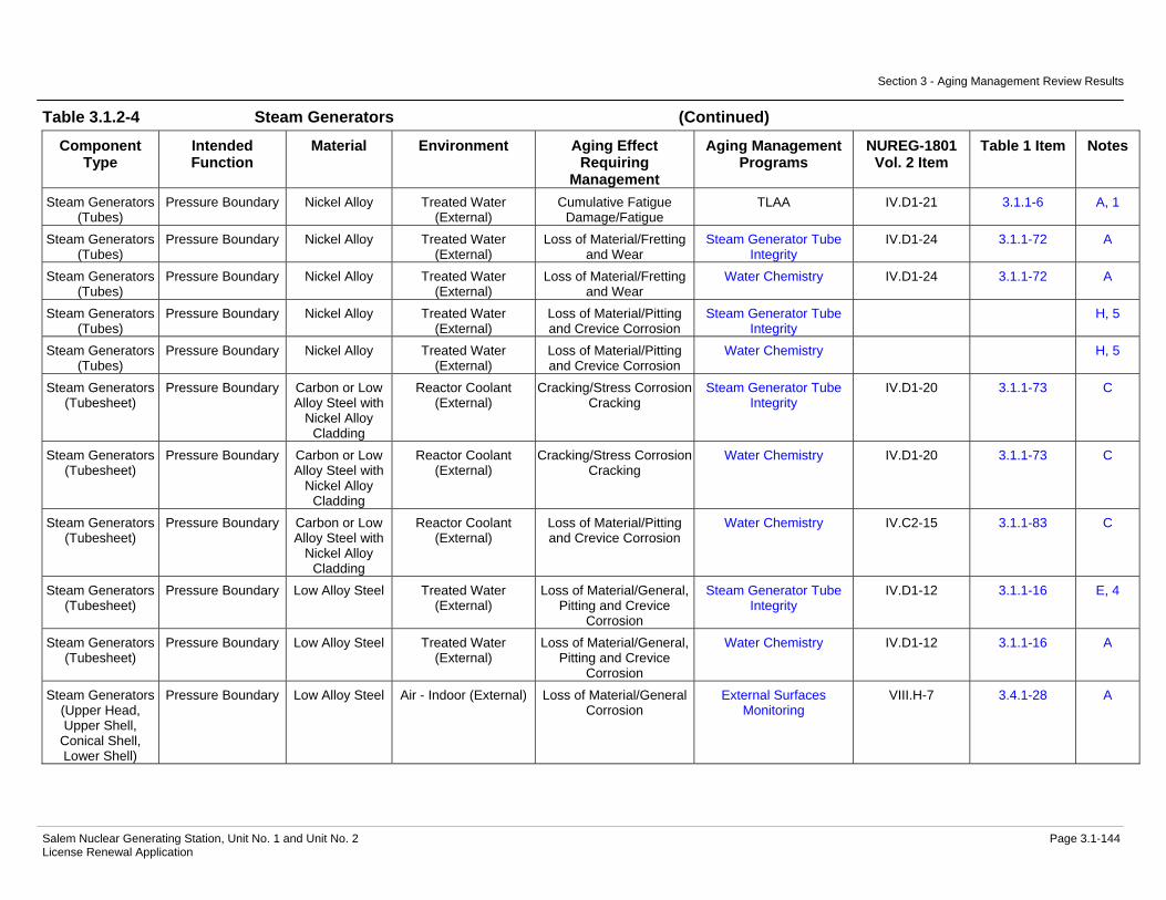
Section 3 - Aging Management Review Results
Salem Nuclear Generating Station, Unit No. 1 and Unit No. 2 Page 3.1-144 License Renewal Application
Table 3.1.2-4 Steam Generators (Continued)
Component Type
Intended Function
Material Environment Aging Effect Requiring
Management
Aging Management Programs
NUREG-1801 Vol. 2 Item
Table 1 Item Notes
Steam Generators (Tubes)
Pressure Boundary Nickel Alloy Treated Water (External)
Cumulative Fatigue Damage/Fatigue
TLAA IV.D1-21 3.1.1-6 A, 1
Steam Generators (Tubes)
Pressure Boundary Nickel Alloy Treated Water (External)
Loss of Material/Fretting and Wear
Steam Generator Tube Integrity
IV.D1-24 3.1.1-72 A
Steam Generators (Tubes)
Pressure Boundary Nickel Alloy Treated Water (External)
Loss of Material/Fretting and Wear
Water Chemistry IV.D1-24 3.1.1-72 A
Steam Generators (Tubes)
Pressure Boundary Nickel Alloy Treated Water (External)
Loss of Material/Pitting and Crevice Corrosion
Steam Generator Tube Integrity
H, 5
Steam Generators (Tubes)
Pressure Boundary Nickel Alloy Treated Water (External)
Loss of Material/Pitting and Crevice Corrosion
Water Chemistry H, 5
Steam Generators (Tubesheet)
Pressure Boundary Carbon or Low Alloy Steel with
Nickel Alloy Cladding
Reactor Coolant (External)
Cracking/Stress Corrosion Cracking
Steam Generator Tube Integrity
IV.D1-20 3.1.1-73 C
Steam Generators (Tubesheet)
Pressure Boundary Carbon or Low Alloy Steel with
Nickel Alloy Cladding
Reactor Coolant (External)
Cracking/Stress Corrosion Cracking
Water Chemistry IV.D1-20 3.1.1-73 C
Steam Generators (Tubesheet)
Pressure Boundary Carbon or Low Alloy Steel with
Nickel Alloy Cladding
Reactor Coolant (External)
Loss of Material/Pitting and Crevice Corrosion
Water Chemistry IV.C2-15 3.1.1-83 C
Steam Generators (Tubesheet)
Pressure Boundary Low Alloy Steel Treated Water (External)
Loss of Material/General, Pitting and Crevice
Corrosion
Steam Generator Tube Integrity
IV.D1-12 3.1.1-16 E, 4
Steam Generators (Tubesheet)
Pressure Boundary Low Alloy Steel Treated Water (External)
Loss of Material/General, Pitting and Crevice
Corrosion
Water Chemistry IV.D1-12 3.1.1-16 A
Steam Generators (Upper Head, Upper Shell,
Conical Shell, Lower Shell)
Pressure Boundary Low Alloy Steel Air - Indoor (External) Loss of Material/General Corrosion
External Surfaces Monitoring
VIII.H-7 3.4.1-28 A

Section 3 - Aging Management Review Results
Salem Nuclear Generating Station, Unit No. 1 and Unit No. 2 Page 3.1-145 License Renewal Application
Table 3.1.2-4 Steam Generators (Continued)
Component Type
Intended Function
Material Environment Aging Effect Requiring
Management
Aging Management Programs
NUREG-1801 Vol. 2 Item
Table 1 Item Notes
Steam Generators (Upper Head, Upper Shell,
Conical Shell, Lower Shell)
Pressure Boundary Low Alloy Steel Air with Borated Water Leakage (External)
Loss of Material/Boric Acid Corrosion
Boric Acid Corrosion IV.D1-3 3.1.1-58 A
Steam Generators (Upper Head, Upper Shell,
Conical Shell, Lower Shell)
Pressure Boundary Low Alloy Steel Treated Water (Internal) Cumulative Fatigue Damage/Fatigue
TLAA IV.D1-11 3.1.1-7 A, 1
Steam Generators (Upper Head, Upper Shell,
Conical Shell, Lower Shell)
Pressure Boundary Low Alloy Steel Treated Water (Internal) Loss of Material/General, Pitting and Crevice
Corrosion
ASME Section XI Inservice Inspection,
Subsections IWB, IWC, and IWD
IV.D1-12 3.1.1-16 A
Steam Generators (Upper Head, Upper Shell,
Conical Shell, Lower Shell)
Pressure Boundary Low Alloy Steel Treated Water (Internal) Loss of Material/General, Pitting and Crevice
Corrosion
Water Chemistry IV.D1-12 3.1.1-16 A
Tanks (steam generator
blowdown and drains receiver
tanks)
Leakage Boundary Carbon Steel Air - Indoor (External) Loss of Material/General Corrosion
External Surfaces Monitoring
VIII.H-7 3.4.1-28 A
Tanks (steam generator
blowdown and drains receiver
tanks)
Leakage Boundary Carbon Steel Air with Borated Water Leakage (External)
Loss of Material/Boric Acid Corrosion
Boric Acid Corrosion VIII.H-9 3.4.1-38 A
Tanks (steam generator
blowdown and drains receiver
tanks)
Leakage Boundary Carbon Steel Treated Water (Internal) Loss of Material/General, Pitting and Crevice
Corrosion
One-Time Inspection VIII.E-40 3.4.1-6 A
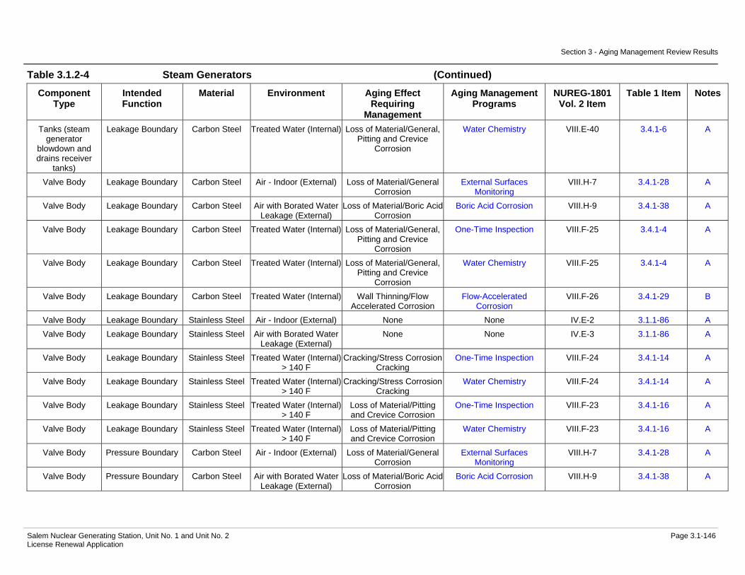
Section 3 - Aging Management Review Results
Salem Nuclear Generating Station, Unit No. 1 and Unit No. 2 Page 3.1-146 License Renewal Application
Table 3.1.2-4 Steam Generators (Continued)
Component Type
Intended Function
Material Environment Aging Effect Requiring
Management
Aging Management Programs
NUREG-1801 Vol. 2 Item
Table 1 Item Notes
Tanks (steam generator
blowdown and drains receiver
tanks)
Leakage Boundary Carbon Steel Treated Water (Internal) Loss of Material/General, Pitting and Crevice
Corrosion
Water Chemistry VIII.E-40 3.4.1-6 A
Valve Body Leakage Boundary Carbon Steel Air - Indoor (External) Loss of Material/General Corrosion
External Surfaces Monitoring
VIII.H-7 3.4.1-28 A
Valve Body Leakage Boundary Carbon Steel Air with Borated Water Leakage (External)
Loss of Material/Boric Acid Corrosion
Boric Acid Corrosion VIII.H-9 3.4.1-38 A
Valve Body Leakage Boundary Carbon Steel Treated Water (Internal) Loss of Material/General, Pitting and Crevice
Corrosion
One-Time Inspection VIII.F-25 3.4.1-4 A
Valve Body Leakage Boundary Carbon Steel Treated Water (Internal) Loss of Material/General, Pitting and Crevice
Corrosion
Water Chemistry VIII.F-25 3.4.1-4 A
Valve Body Leakage Boundary Carbon Steel Treated Water (Internal) Wall Thinning/Flow Accelerated Corrosion
Flow-Accelerated Corrosion
VIII.F-26 3.4.1-29 B
Valve Body Leakage Boundary Stainless Steel Air - Indoor (External) None None IV.E-2 3.1.1-86 A Valve Body Leakage Boundary Stainless Steel Air with Borated Water
Leakage (External) None None IV.E-3 3.1.1-86 A
Valve Body Leakage Boundary Stainless Steel Treated Water (Internal) > 140 F
Cracking/Stress Corrosion Cracking
One-Time Inspection VIII.F-24 3.4.1-14 A
Valve Body Leakage Boundary Stainless Steel Treated Water (Internal) > 140 F
Cracking/Stress Corrosion Cracking
Water Chemistry VIII.F-24 3.4.1-14 A
Valve Body Leakage Boundary Stainless Steel Treated Water (Internal) > 140 F
Loss of Material/Pitting and Crevice Corrosion
One-Time Inspection VIII.F-23 3.4.1-16 A
Valve Body Leakage Boundary Stainless Steel Treated Water (Internal) > 140 F
Loss of Material/Pitting and Crevice Corrosion
Water Chemistry VIII.F-23 3.4.1-16 A
Valve Body Pressure Boundary Carbon Steel Air - Indoor (External) Loss of Material/General Corrosion
External Surfaces Monitoring
VIII.H-7 3.4.1-28 A
Valve Body Pressure Boundary Carbon Steel Air with Borated Water Leakage (External)
Loss of Material/Boric Acid Corrosion
Boric Acid Corrosion VIII.H-9 3.4.1-38 A
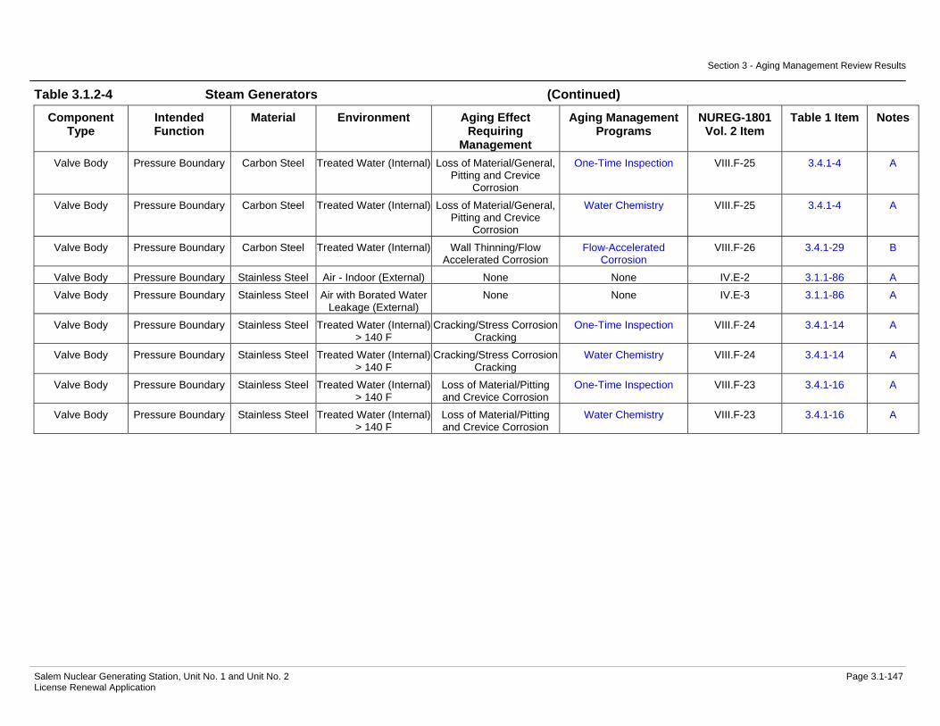
Section 3 - Aging Management Review Results
Salem Nuclear Generating Station, Unit No. 1 and Unit No. 2 Page 3.1-147 License Renewal Application
Table 3.1.2-4 Steam Generators (Continued)
Component Type
Intended Function
Material Environment Aging Effect Requiring
Management
Aging Management Programs
NUREG-1801 Vol. 2 Item
Table 1 Item Notes
Valve Body Pressure Boundary Carbon Steel Treated Water (Internal) Loss of Material/General, Pitting and Crevice
Corrosion
One-Time Inspection VIII.F-25 3.4.1-4 A
Valve Body Pressure Boundary Carbon Steel Treated Water (Internal) Loss of Material/General, Pitting and Crevice
Corrosion
Water Chemistry VIII.F-25 3.4.1-4 A
Valve Body Pressure Boundary Carbon Steel Treated Water (Internal) Wall Thinning/Flow Accelerated Corrosion
Flow-Accelerated Corrosion
VIII.F-26 3.4.1-29 B
Valve Body Pressure Boundary Stainless Steel Air - Indoor (External) None None IV.E-2 3.1.1-86 A Valve Body Pressure Boundary Stainless Steel Air with Borated Water
Leakage (External) None None IV.E-3 3.1.1-86 A
Valve Body Pressure Boundary Stainless Steel Treated Water (Internal)> 140 F
Cracking/Stress Corrosion Cracking
One-Time Inspection VIII.F-24 3.4.1-14 A
Valve Body Pressure Boundary Stainless Steel Treated Water (Internal) > 140 F
Cracking/Stress Corrosion Cracking
Water Chemistry VIII.F-24 3.4.1-14 A
Valve Body Pressure Boundary Stainless Steel Treated Water (Internal) > 140 F
Loss of Material/Pitting and Crevice Corrosion
One-Time Inspection VIII.F-23 3.4.1-16 A
Valve Body Pressure Boundary Stainless Steel Treated Water (Internal) > 140 F
Loss of Material/Pitting and Crevice Corrosion
Water Chemistry VIII.F-23 3.4.1-16 A

Section 3 - Aging Management Review Results
Salem Nuclear Generating Station, Unit No. 1 and Unit No. 2 Page 3.1-148 License Renewal Application
Notes Definition of Note
A Consistent with NUREG-1801 item for component, material, environment, and aging effect. AMP is consistent with NUREG-1801 AMP.
B Consistent with NUREG-1801 item for component, material, environment, and aging effect. AMP takes some exceptions to NUREG-1801 AMP.
C Component is different, but consistent with NUREG-1801 item for material, environment, and aging effect. AMP is consistent with NUREG-1801 AMP.
D Component is different, but consistent with NUREG-1801 item for material, environment, and aging effect. AMP takes some exceptions to NUREG-1801 AMP.
E Consistent with NUREG-1801 item for material, environment and aging effect, but a different aging management program is credited or NUREG-1801 identifies a plant-specific aging management program.
F Material not in NUREG-1801 for this component.
G Environment not in NUREG-1801 for this component and material.
H Aging effect not in NUREG-1801 for this component, material and environment combination.
I Aging effect in NUREG-1801 for this component, material and environment combination is not applicable.
J Neither the component nor the material and environment combination is evaluated in NUREG-1801.
Plant Specific Notes:
1. The TLAA designation in the Aging Management Program column indicates fatigue of this component is evaluated in Section 4.3.
2. NUREG-1801 does not have an Aging Management Program for loss of material/pitting and crevice corrosion for nickel alloy in a treated water (secondary feedwater/steam) environment. The Water Chemistry and One-Time Inspection programs will be used to manage the aging effects applicable to this component type, material, and environment combination.
3. The Steam Generator Tube Integrity program is substituted to manage the aging effect(s) applicable to this component type, material, and environment combination.
4. This environment is not in NUREG-1801 for this component and material. The nickel alloy material located indoors and subject to an air with borated water leakage environment is not subject to aging effects beyond those experienced in a reactor coolant environment that includes cracking/stress corrosion cracking. These aging effects are already accounted for and are managed by the Nickel Alloy Aging Management Program that inspects the external surfaces of the nickel alloy materials.

Section 3 - Aging Management Review Results
Salem Nuclear Generating Station, Unit No. 1 and Unit No. 2 Page 3.1-149 License Renewal Application
5. The aging effect/mechanism of loss of material due to pitting and crevice corrosion is not in NUREG-1801 for this component, material, and environment, however, it is applicable to this combination. The Water Chemistry and Steam Generator Tube Integrity programs are used to manage the aging effects for this component, material, and environment combination.
6. The aging effect/mechanism of reduction of heat transfer due to fouling is not in NUREG-1801 for this component, material, and environment, however, it is applicable to this combination. The Water Chemistry program and Steam Generator Tube Integrity program are used to manage the aging effects for this component, material, and environment combination.

Section 3 – Aging Management Review Results
_________________________________________________________________________________________________ Salem Nuclear Generating Station, Unit No. 1 and Unit No. 2 Page 3.2-1 License Renewal Application
3.2 AGING MANAGEMENT OF ENGINEERED SAFETY FEATURES
3.2.1 INTRODUCTION This section provides the results of the aging management review for those components identified in Section 2.3.2, Engineered Safety Features, as being subject to aging management review. The systems, or portions of systems, which are addressed in this section are described in the indicated sections.
• Containment Spray System (2.3.2.1)
• Residual Heat Removal System (2.3.2.2)
• Safety Injection System (2.3.2.3)
3.2.2 RESULTS
The following tables summarize the results of the aging management review for Engineered Safety Features. Table 3.2.2-1 Summary of Aging Management Evaluation – Containment Spray System Table 3.2.2-2 Summary of Aging Management Evaluation – Residual Heat Removal System Table 3.2.2-3 Summary of Aging Management Evaluation – Safety Injection System
3.2.2.1 Materials, Environments, Aging Effects Requiring Management And Aging Managements Programs
3.2.2.1.1 Containment Spray System
Materials
The materials of construction for the Containment Spray System components are:
• Carbon and Low Alloy Steel Bolting
• Stainless Steel
Environments
The Containment Spray System components are exposed to the following environments:
• Air - Indoor

Section 3 – Aging Management Review Results
_________________________________________________________________________________________________ Salem Nuclear Generating Station, Unit No. 1 and Unit No. 2 Page 3.2-2 License Renewal Application
• Air with Borated Water Leakage
• Air with Steam or Water Leakage
• Air/Gas - Dry
• Air/Gas - Wetted
• Treated Borated Water
• Treated Water
Aging Effects Requiring Management
The following aging effects associated with the Containment Spray System components require management:
• Loss of Material/Boric Acid Corrosion
• Loss of Material/General, Pitting and Crevice Corrosion
• Loss of Preload/Thermal Effects, Gasket Creep, and Self-Loosening
Aging Management Programs
The following aging management programs manage the aging effects for the Containment Spray System components:
• Bolting Integrity (B.2.1.9)
• Boric Acid Corrosion (B.2.1.4)
• One-Time Inspection (B.2.1.20)
• Periodic Inspection (B.2.2.2)
• Water Chemistry (B.2.1.2)
Table 3.2.2-1, Summary of Aging Management Evaluation – Containment Spray System summarizes the results of the aging management review for the Containment Spray System.
3.2.2.1.2 Residual Heat Removal System
Materials
The materials of construction for the Residual Heat Removal System components are:
• Carbon and Low Alloy Steel Bolting
• Stainless Steel Bolting
• Stainless Steel

Section 3 – Aging Management Review Results
_________________________________________________________________________________________________ Salem Nuclear Generating Station, Unit No. 1 and Unit No. 2 Page 3.2-3 License Renewal Application
Environments
The Residual Heat Removal System components are exposed to the following environments:
• Air – Indoor
• Air with Borated Water Leakage
• Air with Steam or Water Leakage
• Treated Borated Water
• Treated Borated Water > 140 oF
Aging Effects Requiring Management
The following aging effects associated with the Residual Heat Removal System components require management:
• Cracking/Stress Corrosion Cracking
• Cumulative Fatigue Damage/Fatigue
• Loss of Material/Boric Acid Corrosion
• Loss of Material/General, Pitting and Crevice Corrosion
• Loss of Preload/Thermal Effects, Gasket Creep, and Self-Loosening
Aging Management Programs
The following aging management programs manage the aging effects for the Residual Heat Removal System components:
• Bolting Integrity (B.2.1.9)
• Boric Acid Corrosion (B.2.1.4)
• Periodic Inspection (B.2.2.2)
• TLAA
• Water Chemistry (B.2.1.2)
Table 3.2.2-2, Summary of Aging Management Evaluation – Residual Heat Removal System summarizes the results of the aging management review for the Residual Heat Removal System.
3.2.2.1.3 Safety Injection System
Materials
The materials of construction for the Safety Injection System components are:
• Carbon and Low Alloy Steel Bolting
• Carbon or Low Alloy Steel with Stainless Steel Cladding

Section 3 – Aging Management Review Results
_________________________________________________________________________________________________ Salem Nuclear Generating Station, Unit No. 1 and Unit No. 2 Page 3.2-4 License Renewal Application
• Carbon Steel
• Cast Austenitic Stainless Steel (CASS)
• Stainless Steel
• Stainless Steel Bolting
Environments
The Safety Injection System components are exposed to the following environments:
• Air - Indoor
• Air - Outdoor
• Air with Borated Water Leakage
• Air with Steam or Water Leakage
• Air/Gas - Dry
• Air/Gas - Wetted
• Closed Cycle Cooling Water > 140 oF
• Soil
• Treated Borated Water
• Treated Borated Water > 140 oF
Aging Effects Requiring Management
The following aging effects associated with the Safety Injection System components require management:
• Cracking/Stress Corrosion Cracking
• Cumulative Fatigue Damage/Fatigue
• Loss of Material/Boric Acid Corrosion
• Loss of Material/Erosion
• Loss of Material/General, Pitting and Crevice Corrosion, and Microbiologically-Influenced Corrosion
• Loss of Preload/Thermal Effects, Gasket Creep, and Self-Loosening
Aging Management Programs
The following aging management programs manage the aging effects for the Safety Injection System components:
• Aboveground Non-Steel Tanks (B.2.2.3)
• ASME Section XI In-service Inspection, Subsections IWB, IWC, and IWD (B.2.1.1)

Section 3 – Aging Management Review Results
_________________________________________________________________________________________________ Salem Nuclear Generating Station, Unit No. 1 and Unit No. 2 Page 3.2-5 License Renewal Application
• Bolting Integrity (B.2.1.9)
• Boric Acid Corrosion (B.2.1.4)
• Closed-Cycle Cooling Water System (B.2.1.12)
• External Surfaces Monitoring (B.2.1.24)
• Inspection of Internal Surfaces in Miscellaneous Piping and Ducting Components (B.2.1.26)
• One-Time Inspection of ASME Code Class 1 Small Bore-Piping (B.2.1.23)
• Periodic Inspection (B.2.2.2)
• TLAA
• Water Chemistry (B.2.1.2)
Table 3.2.2-3, Summary of Aging Management Evaluation – Safety Injection System summarizes the results of the aging management review for the Safety Injection System.
3.2.2.2 AMR Results for Which Further Evaluation is Recommended by the GALL Report
NUREG-1801 provides the basis for identifying those programs that warrant further evaluation by the reviewer in the license renewal application. For the Engineered Safety Features, those programs are addressed in the following subsections.
3.2.2.2.1 Cumulative Fatigue Damage
Fatigue is a TLAA as defined in 10 CFR 54.3. TLAAs are required to be evaluated in accordance with 10 CFR 54.21(c). The evaluation of metal fatigue as a TLAA for the Residual Heat Removal and Safety Injection Systems is discussed in Section 4.3.
3.2.2.2.2 Loss of Material due to Cladding Breach
Loss of material due to cladding breach could occur for PWR steel pump casings with stainless steel cladding exposed to treated borated water. The GALL Report references NRC Information Notice 94-63, Boric Acid Corrosion of Charging Pump Casings Caused by Cladding Cracks, and recommends further evaluation of a plant-specific AMP to ensure that the aging effect is adequately managed. Acceptance criteria are described in Branch Technical Position RLSB-1.
Item Number 3.2.1-2 is not applicable to Salem. Only Salem Unit 2 has carbon steel with stainless steel cladding charging pump casings, which are evaluated in Table 3.3 Item Numbers 3.3.1-35 and 3.3.1-91, as part of the Chemical and Volume Control System.

Section 3 – Aging Management Review Results
_________________________________________________________________________________________________ Salem Nuclear Generating Station, Unit No. 1 and Unit No. 2 Page 3.2-6 License Renewal Application
3.2.2.2.3 Loss of Material due to Pitting and Crevice Corrosion
1. Loss of material due to pitting and crevice corrosion could occur for internal surfaces of stainless steel containment isolation piping, piping components, and piping elements exposed to treated water. The existing AMP relies on monitoring and control of water chemistry to mitigate degradation. However, control of water chemistry does not preclude loss of material due to pitting and crevice corrosion at locations of stagnant flow conditions. Therefore, the effectiveness of the chemistry control program should be verified to ensure that corrosion is not occurring. The GALL Report recommends further evaluation of programs to verify the effectiveness of the chemistry control program. A one-time inspection of select components at susceptible locations is an acceptable method to determine whether an aging effect is not occurring or an aging effect is progressing very slowly such that the component’s intended function will be maintained during the period of extended operation.
Item Number 3.2.1-3 is not applicable to Salem. The stainless steel piping and piping components internal surfaces in the Engineered Safety Features are exposed to treated borated water and are evaluated with Item Number 3.2.1-49. Water Chemistry program activities provide for monitoring and controlling the chemical environments of the primary cycle systems in accordance with EPRI, Pressurized Water Reactor Primary Chemistry Guidelines. The Water Chemistry program activities mitigate the loss of material aging effect to ensure there is no loss of component intended function.
2. Loss of material from pitting and crevice corrosion could occur for stainless steel piping, piping components, and piping elements exposed to soil. The GALL Report recommends further evaluation of a plant-specific AMP to ensure that the aging effect is adequately managed. Acceptance criteria are described in Branch Technical Position RSLB-1.
Item Number 3.2.1-4 is not applicable to Salem. The piping, piping components, and piping elements external surfaces in the Containment Spray System, Residual Heat Removal System, and Safety Injection System are not exposed to soil, since all of the stainless steel piping, piping components, and piping elements are inside the Auxiliary Building and Containment Structure. However, the Refueling Water Storage Tank in the Safety Injection System has a stainless steel bottom, which is exposed to soil, and the aging effect will be managed in the Aboveground Non-Steel Tanks, B.2.2.3, aging management program, which is described in Appendix B
3. Loss of material from pitting and crevice corrosion could occur for BWR stainless steel and aluminum piping, piping components, and piping elements exposed to treated water. The existing AMP relies on monitoring and control of water chemistry for BWRs to mitigate degradation. However, control of water chemistry does not preclude loss of material due to pitting and crevice corrosion at locations of stagnant flow conditions. Therefore, the effectiveness of the chemistry control
Section 3 – Aging Management Review Results
_________________________________________________________________________________________________ Salem Nuclear Generating Station, Unit No. 1 and Unit No. 2 Page 3.2-7 License Renewal Application
program should be verified to ensure that corrosion is not occurring. The GALL Report recommends further evaluation of programs to verify the effectiveness of the water chemistry control program. A one-time inspection of select components at susceptible locations is an acceptable method to determine whether an aging effect is not occurring or an aging effect is progressing very slowly such that the component’s intended function will be maintained during the period of extended operation.
Item Number 3.2.1-5 is applicable to BWRs only and is not used for Salem.
4. Loss of material from pitting and crevice corrosion could occur for stainless steel and copper alloy piping, piping components, and piping elements exposed to lubricating oil. The existing program relies on the periodic sampling and analysis of lubricating oil to maintain contaminants within acceptable limits, thereby preserving an environment that is not conducive to corrosion. However, control of lube oil contaminants may not always have been adequate to preclude corrosion. Therefore, the effectiveness of lubricating oil control should be verified to ensure that corrosion is not occurring. The GALL Report recommends further evaluation to verify the effectiveness of the lubricating oil program. A one-time inspection of selected components at susceptible locations is an acceptable method to ensure that corrosion is not occurring and that the component’s intended function will be maintained during the period of extended operation.
Item Number 3.2.1-6 is not applicable to Engineered Safety Features Systems. There are no stainless steel and copper alloy piping, piping components, and piping elements exposed to lubricating oil in the Engineered Safety Features Systems. However, the Safety Injection System pump lube oil coolers are titanium and are evaluated with the Service Water System. Salem will implement a One-Time Inspection program, B.2.1.20, for susceptible locations to verify the effectiveness of the Lubricating Oil Analysis program, B.2.1.27, to manage the loss of material due to pitting and crevice corrosion in titanium pump lube oil coolers exposed to lubricating oil in the Safety Injection System. The Lubricating Oil Analysis and One-Time Inspection programs are described in Appendix B.
5. Loss of material from pitting and crevice corrosion could occur for of partially encased stainless steel tanks exposed to raw water due to cracking of the perimeter seal from weathering. The GALL Report recommends further evaluation to ensure that the aging effect is adequately managed. The GALL Report recommends that a plant-specific AMP be evaluated because moisture and water can egress under the tank if the perimeter seal is degraded. Acceptance criteria are described in Branch Technical Position RSLB-1.
Item Number 3.2.1-7 is not applicable to Salem. There are no partially encased stainless steel tanks with breached moisture barrier exposed to raw water in the Salem Engineered Safety Features systems.

Section 3 – Aging Management Review Results
_________________________________________________________________________________________________ Salem Nuclear Generating Station, Unit No. 1 and Unit No. 2 Page 3.2-8 License Renewal Application
6. Loss of material from pitting and crevice corrosion could occur for stainless steel piping, piping components, piping elements, and tanks exposed to internal condensation. The GALL Report recommends further evaluation of a plant-specific AMP to ensure that the aging effect is adequately managed. Acceptance criteria are described in Branch Technical Position RSLB-1.
Salem will implement the Periodic Inspection program, B.2.2.2, to manage the loss of material due to pitting and crevice corrosion in stainless steel piping, piping components, piping elements internal surfaces exposed to an air/gas wetted environment in the Containment Spray System. The Periodic Inspection program is used to manage the aging effects of components that are not covered by other aging management programs, including external surfaces and internal surfaces of non-steel components. The Periodic Inspection program includes visual inspections, physical manipulation and nondestructive volumetric examinations to assure that existing environmental conditions are not causing material degradation that could result in a loss of component intended functions. The Periodic Inspection program is described in Appendix B.
3.2.2.2.4 Reduction of Heat Transfer due to Fouling
1. Reduction of heat transfer due to fouling could occur for steel, stainless steel, and copper alloy heat exchanger tubes exposed to lubricating oil. The existing AMP relies on monitoring and control of lube oil chemistry to mitigate reduction of heat transfer due to fouling. However, control of lube oil chemistry may not always have been adequate to preclude fouling. Therefore, the effectiveness of lube oil chemistry control should be verified to ensure that fouling is not occurring. The GALL Report recommends further evaluation of programs to verify the effectiveness of lube oil chemistry control. A one-time inspection of select components at susceptible locations is an acceptable method to determine whether an aging effect is not occurring or an aging effect is progressing very slowly such that the component’s intended function will be maintained during the period of extended operation.
Item Number 3.2.1-9 is not applicable to Engineered Safety Features Systems. There are no steel, stainless steel and copper alloy heat exchanger tubes exposed to lubricating oil in the Engineered Safety Features Systems. However, the Safety Injection System pump lube oil coolers are titanium and are evaluated with the Service Water System. Salem will implement a One-Time Inspection program, B.2.1.20, for susceptible locations to verify the effectiveness of the Lubricating Oil Analysis program, B.2.1.27, to manage the loss of material due to pitting and crevice corrosion in titanium pump lube oil coolers exposed to lubricating oil in the Safety Injection System. The Lubricating Oil Analysis and One-Time Inspection programs are described in Appendix B.
2. Reduction of heat transfer due to fouling could occur for stainless steel heat exchanger tubes exposed to treated water. The existing program

Section 3 – Aging Management Review Results
_________________________________________________________________________________________________ Salem Nuclear Generating Station, Unit No. 1 and Unit No. 2 Page 3.2-9 License Renewal Application
relies on control of water chemistry to manage reduction of heat transfer due to fouling. However, control of water chemistry may have been inadequate. Therefore, the GALL report recommends that the effectiveness of the chemistry control program should be verified to ensure that reduction of heat transfer due to fouling is not occurring. A one-time inspection is an acceptable method to ensure that reduction of heat transfer is not occurring and that the component’s intended function will be maintained during the period of extended operation.
Salem will implement a One-Time Inspection program, B.2.1.20, for susceptible locations to verify the effectiveness of the Water Chemistry program, B.2.1.2, to manage the reduction of heat transfer due to fouling in stainless steel heat exchanger components exposed to treated water in the Residual Heat Removal heat exchanger evaluated with the Component Cooling System. The Water Chemistry and One-Time Inspection programs are described in Appendix B.
3.2.2.2.5 Hardening and Loss of Strength due to Elastomer Degradation
Item Number 3.2.1-11 is applicable to BWRs only and is not used for Salem.
3.2.2.2.6 Loss of Material due to Erosion
Loss of material due to erosion could occur in the stainless steel high pressure safety injection (HPSI) pump mini-flow recirculation orifice exposed to treated borated water. The GALL Report recommends a plant-specific AMP be evaluated for erosion of the orifice due to extended use of the centrifugal HPSI pump for normal charging. The GALL Report references Licensee Event Report (LER) 50-275/94-023 for evidence of erosion. Further evaluation is recommended to ensure that the aging effect is adequately managed. Acceptance criteria are described in Branch Technical Position RSLB-1.
Salem will implement the Water Chemistry program, B.2.1.2, to manage the loss of material due to erosion in the stainless steel charging pump mini-flow recirculation orifice in the Chemical & Volume Control System. The high-pressure charging pumps are not used for normal charging flow, unless the positive displacement pump is out of service for maintenance. The positive displacement pump does not have flow through the recirculation orifice. Therefore, an additional inspection of the orifice is not warranted to manage the aging effect of erosion on the mini-flow recirculation orifice. The Water Chemistry program is described in Appendix B.
The Safety Injection System also has mini-flow recirculation orifices, but they only have flow going through them a few hours every quarter for surveillance testing. Therefore, an additional inspection of the orifices is not warranted to manage the aging effect of erosion on the mini-flow recirculation orifice.

Section 3 – Aging Management Review Results
_________________________________________________________________________________________________ Salem Nuclear Generating Station, Unit No. 1 and Unit No. 2 Page 3.2-10 License Renewal Application
3.2.2.2.7 Loss of Material due to General Corrosion and Fouling
Item Number 3.2.1-13 is applicable to BWRs only and is not used for Salem. 3.2.2.2.8 Loss of Material due to General, Pitting, and Crevice Corrosion
1. Item Number 3.2.1-14 is applicable to BWRs only and is not used for Salem.
2. Loss of material due to general, pitting and crevice corrosion could occur for the internal surfaces of steel containment isolation piping, piping components, and piping elements exposed to treated water. The existing AMP relies on monitoring and control of water chemistry to mitigate degradation. However, control of water chemistry does not preclude loss of material due to general, pitting, and crevice corrosion at locations of stagnant flow conditions. Therefore, the effectiveness of the water chemistry control program should be verified to ensure that corrosion is not occurring. The GALL Report recommends further evaluation of programs to verify the effectiveness of the chemistry control program. A one-time inspection of select components at susceptible locations is an acceptable method to determine whether an aging effect is not occurring or an aging effect is progressing very slowly such that the component’s intended function will be maintained during the period of extended operation. Item Number 3.2.1-15 is not applicable to Salem. There is no steel containment isolation piping, piping components, and piping elements exposed to treated water in the Engineered Safety Features systems.
3. Loss of material due to general, pitting and crevice corrosion could occur for steel piping, piping components, and piping elements exposed to lubricating oil. The existing program relies on the periodic sampling and analysis of lubricating oil to maintain contaminants within acceptable limits, thereby preserving an environment that is not conducive to corrosion. However, control of lube oil contaminants may not always have been adequate to preclude corrosion. Therefore, the effectiveness of lubricating oil control should be verified to ensure that corrosion is not occurring. The GALL Report recommends further evaluation to verify the effectiveness of the lubricating oil program. A one-time inspection of selected components at susceptible locations is an acceptable method to ensure that corrosion is not occurring and that the component’s intended function will be maintained during the period of extended operation. Item Number 3.2.1-16 is not applicable to Salem. There is no steel piping, piping components, and piping elements exposed to lubricating oil in the Engineered Safety Features systems.
Section 3 – Aging Management Review Results
_________________________________________________________________________________________________ Salem Nuclear Generating Station, Unit No. 1 and Unit No. 2 Page 3.2-11 License Renewal Application
3.2.2.2.9 Loss of Material due to General, Pitting, Crevice, and Microbiologically-Influenced Corrosion (MIC)
Loss of material due to general, pitting, crevice, and MIC could occur for steel (with or without coating or wrapping) piping, piping components, and piping elements buried in soil. The buried piping and tanks inspection program relies on industry practice, frequency of pipe excavation, and operating experience to manage the effects of loss of material from general, pitting, and crevice corrosion and MIC. The effectiveness of the buried piping and tanks inspection program should be verified to evaluate an applicant's inspection frequency and operating experience with buried components, ensuring that loss of material is not occurring. Item Number 3.2.1-17 is not applicable to Salem. There is no steel piping, piping components, and piping elements buried in soil in the Engineered Safety Features systems.
3.2.2.2.10 Quality Assurance for Aging Management of Non Safety-Related Components QA provisions applicable to License Renewal are discussed in Section B.1.3.
3.2.2.3 Time-Limited Aging Analyses
The time-limited aging analyses identified below are associated with the Engineered Safety Features components: • Section 4.3, Metal Fatigue of Piping and Components
3.2.3 CONCLUSION
The Engineered Safety Features piping, fittings and components that are subject to aging management review have been identified in accordance with the requirements of 10 CFR 54.4. The aging management programs selected to manage aging effects for the Engineered Safety Features components are identified in the summaries in Section 3.2.2.1 above.
A description of these aging management programs is provided in Appendix B, along with the demonstration that the identified aging effects will be managed for the period of extended operation.
Therefore, based on the conclusions provided in Appendix B, the effects of aging associated with the Engineered Safety Features components will be adequately managed so that there is reasonable assurance that the intended function(s) will be maintained consistent with the current licensing basis during the period of extended operation.

Section 3 - Aging Management Review Results
Salem Nuclear Generating Station, Unit No. 1 and Unit No. 2 Page 3.2-12 License Renewal Application
Table 3.2.1 Summary of Aging Management Evaluations for the Engineered Safety Features
Item Number
Component Aging Effect/Mechanism
Aging Management
Programs
Further Evaluation
Recommended
Discussion
3.2.1-1 Steel and stainless steel piping, piping components, and piping elements in emergency core cooling system
Cumulative fatigue damage
TLAA, evaluated in accordance with 10 CFR 54.21(c)
Yes, TLAA
Fatigue is a TLAA; further evaluation is documented in Subsection 3.2.2.2.1.
3.2.1-2 Steel with stainless steel cladding pump casing exposed to treated borated water
Loss of material due to cladding breach
A plant-specific aging management program is to be evaluated. Reference NRC Information Notice 94-63, “Boric Acid Corrosion of Charging Pump Casings Caused by Cladding Cracks"
Yes, verify that plant-specific program addresses cladding breach
Not Applicable.
See Subsection 3.2.2.2.2.
3.2.1-3 Stainless steel containment isolation piping and components internal surfaces exposed to treated water
Loss of material due to pitting and crevice corrosion
Water Chemistry and One-Time Inspection
Yes, detection of aging effects is to be evaluated
Not Applicable.
See Subsection 3.2.2.2.3.1.
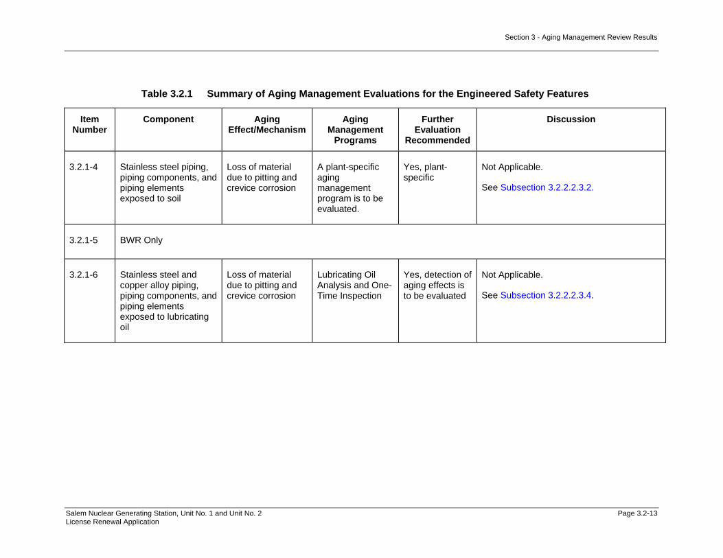
Section 3 - Aging Management Review Results
Salem Nuclear Generating Station, Unit No. 1 and Unit No. 2 Page 3.2-13 License Renewal Application
Table 3.2.1 Summary of Aging Management Evaluations for the Engineered Safety Features
Item Number
Component Aging Effect/Mechanism
Aging Management
Programs
Further Evaluation
Recommended
Discussion
3.2.1-4 Stainless steel piping, piping components, and piping elements exposed to soil
Loss of material due to pitting and crevice corrosion
A plant-specific aging management program is to be evaluated.
Yes, plant-specific
Not Applicable.
See Subsection 3.2.2.2.3.2.
3.2.1-5 BWR Only
3.2.1-6 Stainless steel and copper alloy piping, piping components, and piping elements exposed to lubricating oil
Loss of material due to pitting and crevice corrosion
Lubricating Oil Analysis and One-Time Inspection
Yes, detection of aging effects is to be evaluated
Not Applicable.
See Subsection 3.2.2.2.3.4.

Section 3 - Aging Management Review Results
Salem Nuclear Generating Station, Unit No. 1 and Unit No. 2 Page 3.2-14 License Renewal Application
Table 3.2.1 Summary of Aging Management Evaluations for the Engineered Safety Features
Item Number
Component Aging Effect/Mechanism
Aging Management
Programs
Further Evaluation
Recommended
Discussion
3.2.1-7 Partially encased stainless steel tanks with breached moisture barrier exposed to raw water
Loss of material due to pitting and crevice corrosion
A plant-specific aging management program is to be evaluated for pitting and crevice corrosion of tank bottoms because moisture and water can egress under the tank due to cracking of the perimeter seal from weathering.
Yes, plant-specific
Not Applicable.
See Subsection 3.2.2.2.3.5.
3.2.1-8 Stainless steel piping, piping components, piping elements, and tank internal surfaces exposed to condensation (internal)
Loss of material due to pitting and crevice corrosion
A plant-specific aging management program is to be evaluated.
Yes, plant-specific
The Periodic Inspection program, B.2.2.2, will be used to manage the loss of material due to pitting and crevice corrosion in stainless steel piping, piping components, and piping elements internal surfaces exposed to an air/gas wetted environment.
See Subsection 3.2.2.2.3.6.
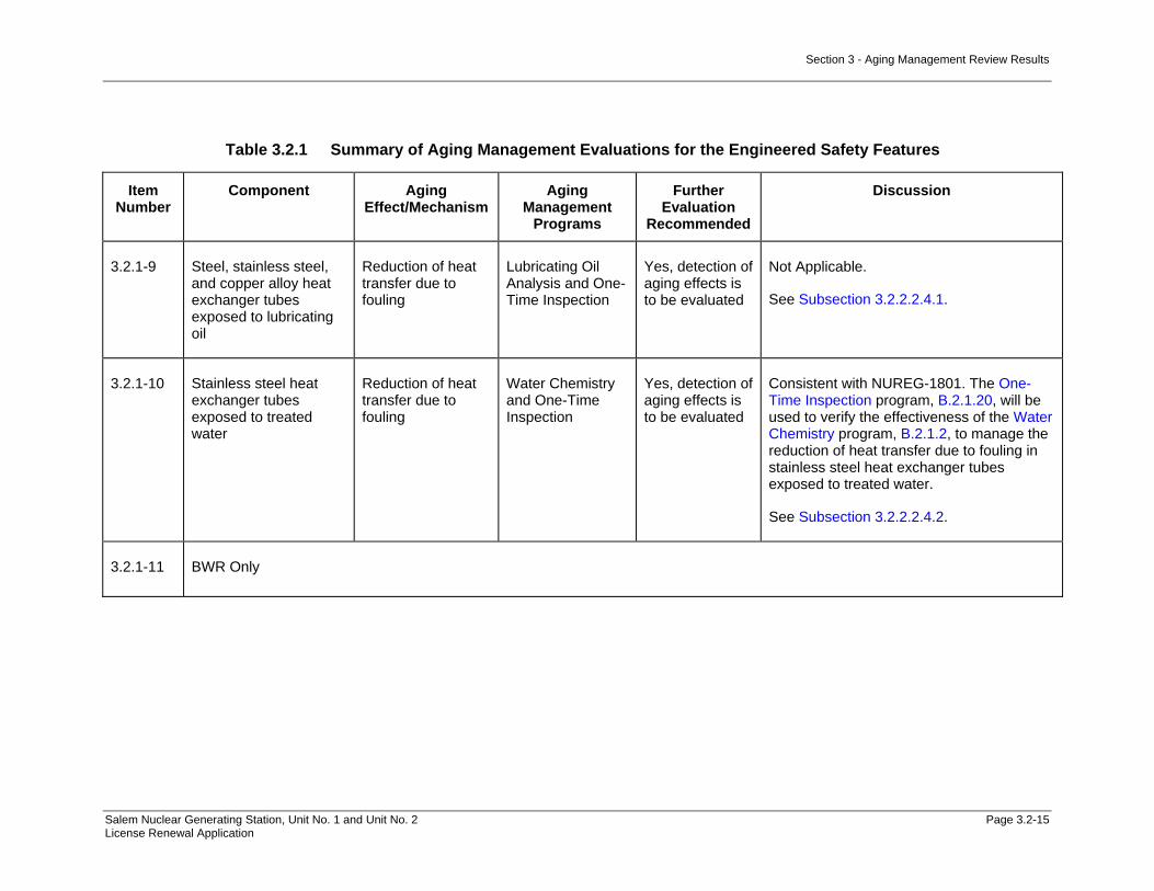
Section 3 - Aging Management Review Results
Salem Nuclear Generating Station, Unit No. 1 and Unit No. 2 Page 3.2-15 License Renewal Application
Table 3.2.1 Summary of Aging Management Evaluations for the Engineered Safety Features
Item Number
Component Aging Effect/Mechanism
Aging Management
Programs
Further Evaluation
Recommended
Discussion
3.2.1-9 Steel, stainless steel, and copper alloy heat exchanger tubes exposed to lubricating oil
Reduction of heat transfer due to fouling
Lubricating Oil Analysis and One-Time Inspection
Yes, detection of aging effects is to be evaluated
Not Applicable.
See Subsection 3.2.2.2.4.1.
3.2.1-10 Stainless steel heat exchanger tubes exposed to treated water
Reduction of heat transfer due to fouling
Water Chemistry and One-Time Inspection
Yes, detection of aging effects is to be evaluated
Consistent with NUREG-1801. The One-Time Inspection program, B.2.1.20, will be used to verify the effectiveness of the Water Chemistry program, B.2.1.2, to manage the reduction of heat transfer due to fouling in stainless steel heat exchanger tubes exposed to treated water.
See Subsection 3.2.2.2.4.2.
3.2.1-11 BWR Only

Section 3 - Aging Management Review Results
Salem Nuclear Generating Station, Unit No. 1 and Unit No. 2 Page 3.2-16 License Renewal Application
Table 3.2.1 Summary of Aging Management Evaluations for the Engineered Safety Features
Item Number
Component Aging Effect/Mechanism
Aging Management
Programs
Further Evaluation
Recommended
Discussion
3.2.1-12 Stainless steel high-pressure safety injection (charging) pump miniflow orifice exposed to treated borated water
Loss of material due to erosion
A plant-specific aging management program is to be evaluated for erosion of the orifice due to extended use of the centrifugal HPSI pump for normal charging.
Yes, plant-specific
The Water Chemistry program, B.2.1.2, will be used to manage the loss of material due to erosion in the stainless steel high-pressure charging pump mini-flow recirculation orifices exposed to treated borated water environment.
See Subsection 3.2.2.2.6.
3.2.1-13 BWR Only
3.2.1-14 BWR Only
3.2.1-15 Steel containment isolation piping, piping components, and piping elements internal surfaces exposed to treated water
Loss of material due to general, pitting, and crevice corrosion
Water Chemistry and One-Time Inspection
Yes, detection of aging effects is to be evaluated
Not Applicable.
See Subsection 3.2.2.2.8.2.
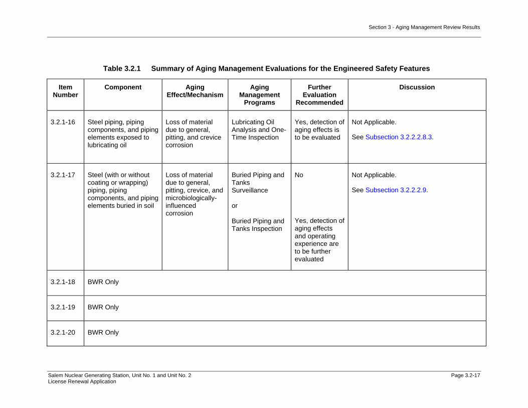
Section 3 - Aging Management Review Results
Salem Nuclear Generating Station, Unit No. 1 and Unit No. 2 Page 3.2-17 License Renewal Application
Table 3.2.1 Summary of Aging Management Evaluations for the Engineered Safety Features
Item Number
Component Aging Effect/Mechanism
Aging Management
Programs
Further Evaluation
Recommended
Discussion
3.2.1-16 Steel piping, piping components, and piping elements exposed to lubricating oil
Loss of material due to general, pitting, and crevice corrosion
Lubricating Oil Analysis and One-Time Inspection
Yes, detection of aging effects is to be evaluated
Not Applicable.
See Subsection 3.2.2.2.8.3.
3.2.1-17 Steel (with or without coating or wrapping) piping, piping components, and piping elements buried in soil
Loss of material due to general, pitting, crevice, and microbiologically-influenced corrosion
Buried Piping and Tanks Surveillance or Buried Piping and Tanks Inspection
No
Yes, detection of aging effects and operating experience are to be further evaluated
Not Applicable.
See Subsection 3.2.2.2.9.
3.2.1-18 BWR Only
3.2.1-19 BWR Only
3.2.1-20 BWR Only
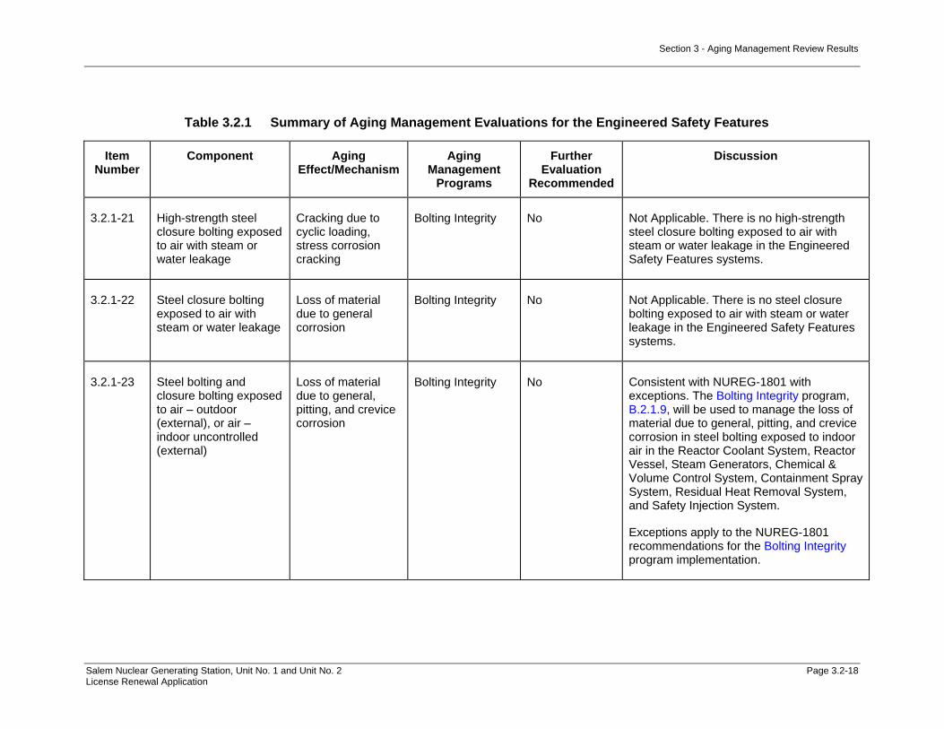
Section 3 - Aging Management Review Results
Salem Nuclear Generating Station, Unit No. 1 and Unit No. 2 Page 3.2-18 License Renewal Application
Table 3.2.1 Summary of Aging Management Evaluations for the Engineered Safety Features
Item Number
Component Aging Effect/Mechanism
Aging Management
Programs
Further Evaluation
Recommended
Discussion
3.2.1-21 High-strength steel closure bolting exposed to air with steam or water leakage
Cracking due to cyclic loading, stress corrosion cracking
Bolting Integrity No Not Applicable. There is no high-strength steel closure bolting exposed to air with steam or water leakage in the Engineered Safety Features systems.
3.2.1-22 Steel closure bolting exposed to air with steam or water leakage
Loss of material due to general corrosion
Bolting Integrity No Not Applicable. There is no steel closure bolting exposed to air with steam or water leakage in the Engineered Safety Features systems.
3.2.1-23 Steel bolting and closure bolting exposed to air – outdoor (external), or air – indoor uncontrolled (external)
Loss of material due to general, pitting, and crevice corrosion
Bolting Integrity No Consistent with NUREG-1801 with exceptions. The Bolting Integrity program, B.2.1.9, will be used to manage the loss of material due to general, pitting, and crevice corrosion in steel bolting exposed to indoor air in the Reactor Coolant System, Reactor Vessel, Steam Generators, Chemical & Volume Control System, Containment Spray System, Residual Heat Removal System, and Safety Injection System.
Exceptions apply to the NUREG-1801 recommendations for the Bolting Integrity program implementation.

Section 3 - Aging Management Review Results
Salem Nuclear Generating Station, Unit No. 1 and Unit No. 2 Page 3.2-19 License Renewal Application
Table 3.2.1 Summary of Aging Management Evaluations for the Engineered Safety Features
Item Number
Component Aging Effect/Mechanism
Aging Management
Programs
Further Evaluation
Recommended
Discussion
3.2.1-24 Steel closure bolting exposed to air – indoor uncontrolled (external)
Loss of preload due to thermal effects, gasket creep, and self-loosening
Bolting Integrity No Consistent with NUREG-1801 with exceptions. The Bolting Integrity program, B.2.1.9, will be used to manage the loss of preload due to thermal effects, gasket creep, and self-loosening in steel closure bolting exposed to indoor air in the Reactor Vessel, Chemical & Volume Control System, Containment Spray System, Residual Heat Removal System, and Safety Injection System.
Exceptions apply to the NUREG-1801 recommendations for Bolting Integrity program implementation.
Components in the Containment Structure have been aligned to this item number based on material, environment and aging effect. The 10 CFR Part 50, Appendix J program, B.2.1.31, and ASME Section XI, Subsection IWE program, B.2.1.28, have been substituted to manage loss of preload due to self-loosening in steel bolting exposed to indoor air in this structure.
Exceptions apply to the NUREG-1801 recommendations for ASME Section XI, Subsection IWE program implementation.

Section 3 - Aging Management Review Results
Salem Nuclear Generating Station, Unit No. 1 and Unit No. 2 Page 3.2-20 License Renewal Application
Table 3.2.1 Summary of Aging Management Evaluations for the Engineered Safety Features
Item Number
Component Aging Effect/Mechanism
Aging Management
Programs
Further Evaluation
Recommended
Discussion
3.2.1-25 Stainless steel piping, piping components, and piping elements exposed to closed cycle cooling water >60°C (>140°F)
Cracking due to stress corrosion cracking
Closed-Cycle Cooling Water System
No Consistent with NUREG-1801 with exceptions. The Closed-Cycle Cooling Water program, B.2.1.12, will be used to manage cracking due to stress corrosion cracking in stainless steel heat exchanger components exposed to closed-cycle cooling water >140°F in the Safety Injection System.
Exceptions apply to the NUREG-1801 recommendations for Closed-Cycle Cooling Water program implementation.
3.2.1-26 Steel piping, piping components, and piping elements exposed to closed cycle cooling water
Loss of material due to general, pitting, and crevice corrosion
Closed-Cycle Cooling Water System
No Not Applicable. There is no steel piping, piping components, and piping elements exposed to closed cycle cooling water in the Engineered Safety Features systems.
3.2.1-27 Steel heat exchanger components exposed to closed cycle cooling water
Loss of material due to general, pitting, crevice, and galvanic corrosion
Closed-Cycle Cooling Water System
No Not Applicable. There are no steel heat exchangers exposed to closed cycle cooling water in the Engineered Safety Features systems.

Section 3 - Aging Management Review Results
Salem Nuclear Generating Station, Unit No. 1 and Unit No. 2 Page 3.2-21 License Renewal Application
Table 3.2.1 Summary of Aging Management Evaluations for the Engineered Safety Features
Item Number
Component Aging Effect/Mechanism
Aging Management
Programs
Further Evaluation
Recommended
Discussion
3.2.1-28 Stainless steel piping, piping components, piping elements, and heat exchanger components exposed to closed-cycle cooling water
Loss of material due to pitting and crevice corrosion
Closed-Cycle Cooling Water System
No Consistent with NUREG-1801 with exceptions. The Closed-Cycle Cooling Water System program, B.2.1.12, will be used to manage the loss of material due to pitting and crevice corrosion in stainless steel Refueling Water Storage Tank heat exchanger components exposed to closed-cycle cooling water in the Safety Injection System. The stainless steel heat exchanger components in the Safety Injection System have been evaluated with the Component Cooling System. See Table 3.3.1 Item Numbers 3.3.1-50 and 3.3.1-52.
Exceptions apply to the NUREG-1801 recommendations for Closed-Cycle Cooling Water System program implementation.
3.2.1-29 Copper alloy piping, piping components, piping elements, and heat exchanger components exposed to closed cycle cooling water
Loss of material due to pitting, crevice, and galvanic corrosion
Closed-Cycle Cooling Water System
No Not Applicable. There are no copper piping, piping components, piping elements, and heat exchanger components exposed to closed cycle cooling water in the Engineered Safety Features systems.

Section 3 - Aging Management Review Results
Salem Nuclear Generating Station, Unit No. 1 and Unit No. 2 Page 3.2-22 License Renewal Application
Table 3.2.1 Summary of Aging Management Evaluations for the Engineered Safety Features
Item Number
Component Aging Effect/Mechanism
Aging Management
Programs
Further Evaluation
Recommended
Discussion
3.2.1-30 Stainless steel and copper alloy heat exchanger tubes exposed to closed cycle cooling water
Reduction of heat transfer due to fouling
Closed-Cycle Cooling Water System
No Consistent with NUREG-1801 with exceptions. The Closed-Cycle Cooling Water System program, B.2.1.12, will be used to manage the reduction of heat transfer due to fouling in stainless steel heat exchanger components exposed to closed-cycle cooling water in the Residual Heat Removal heat exchanger evaluated in the Component Cooling System.
Exceptions apply to the NUREG-1801 recommendations for Closed-Cycle Cooling Water System program implementation.
3.2.1-31 External surfaces of steel components including ducting, piping, ducting closure bolting, and containment isolation piping external surfaces exposed to air - indoor uncontrolled (external); condensation (external) and air - outdoor (external)
Loss of material due to general corrosion
External Surfaces Monitoring
No Consistent with NUREG-1801. The External Surfaces Monitoring program, B.2.1.24, will be used to manage the loss of material due to general corrosion on the external surfaces of steel piping, piping elements, piping components, tanks, and reactor vessel components exposed to indoor air in the Reactor Coolant System, Reactor Vessel, Chemical & Volume Control System, and Safety Injection System.

Section 3 - Aging Management Review Results
Salem Nuclear Generating Station, Unit No. 1 and Unit No. 2 Page 3.2-23 License Renewal Application
Table 3.2.1 Summary of Aging Management Evaluations for the Engineered Safety Features
Item Number
Component Aging Effect/Mechanism
Aging Management
Programs
Further Evaluation
Recommended
Discussion
3.2.1-32 Steel piping and ducting components and internal surfaces exposed to air – indoor uncontrolled (Internal)
Loss of material due to general corrosion
Inspection of Internal Surfaces in Miscellaneous Piping and Ducting Components
No Not Applicable. There are no steel piping and ducting components and internal surfaces exposed to indoor air in the Engineered Safety Features systems. AMR methodology assumes internal surfaces are exposed to an Air/Gas – Wetted environment, which includes condensation. AMR methodology predicts pitting and crevice corrosion in addition to general corrosion. See Item Number 3.2.1-34.
3.2.1-33 Steel encapsulation components exposed to air-indoor uncontrolled (internal)
Loss of material due to general, pitting, and crevice corrosion
Inspection of Internal Surfaces in Miscellaneous Piping and Ducting Components
No Not Applicable. There are no steel encapsulation components exposed to indoor air in the Engineered Safety Features systems.

Section 3 - Aging Management Review Results
Salem Nuclear Generating Station, Unit No. 1 and Unit No. 2 Page 3.2-24 License Renewal Application
Table 3.2.1 Summary of Aging Management Evaluations for the Engineered Safety Features
Item Number
Component Aging Effect/Mechanism
Aging Management
Programs
Further Evaluation
Recommended
Discussion
3.2.1-34 Steel piping, piping components, and piping elements exposed to condensation (internal)
Loss of material due to general, pitting, and crevice corrosion
Inspection of Internal Surfaces in Miscellaneous Piping and Ducting Components
No Consistent with NUREG-1801. The Inspection of Internal Surfaces in Miscellaneous Piping and Ducting Components program, B.2.1.24, will be used to manage the loss of material due to general, pitting, and crevice corrosion on the internal surfaces of steel piping, piping elements, and piping components exposed to air/gas-wetted in the Safety Injection System.
3.2.1-35 Steel containment isolation piping and components internal surfaces exposed to raw water
Loss of material due to general, pitting, crevice, and microbiologically-influenced corrosion, and fouling
Open-Cycle Cooling Water System
No Not Applicable. There are no steel containment isolation piping and components internal surfaces exposed to raw water in the Engineered Safety Features systems.
3.2.1-36 Steel heat exchanger components exposed to raw water
Loss of material due to general, pitting, crevice, galvanic, and microbiologically-influenced corrosion, and fouling
Open-Cycle Cooling Water System
No Not Applicable. There are no steel heat exchanger components exposed to raw water in the Engineered Safety Features systems.
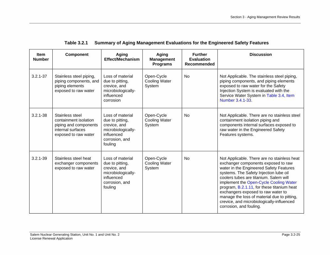
Section 3 - Aging Management Review Results
Salem Nuclear Generating Station, Unit No. 1 and Unit No. 2 Page 3.2-25 License Renewal Application
Table 3.2.1 Summary of Aging Management Evaluations for the Engineered Safety Features
Item Number
Component Aging Effect/Mechanism
Aging Management
Programs
Further Evaluation
Recommended
Discussion
3.2.1-37 Stainless steel piping, piping components, and piping elements exposed to raw water
Loss of material due to pitting, crevice, and microbiologically-influenced corrosion
Open-Cycle Cooling Water System
No Not Applicable. The stainless steel piping, piping components, and piping elements exposed to raw water for the Safety Injection System is evaluated with the Service Water System in Table 3.4, Item Number 3.4.1-33.
3.2.1-38 Stainless steel containment isolation piping and components internal surfaces exposed to raw water
Loss of material due to pitting, crevice, and microbiologically-influenced corrosion, and fouling
Open-Cycle Cooling Water System
No Not Applicable. There are no stainless steel containment isolation piping and components internal surfaces exposed to raw water in the Engineered Safety Features systems.
3.2.1-39 Stainless steel heat exchanger components exposed to raw water
Loss of material due to pitting, crevice, and microbiologically-influenced corrosion, and fouling
Open-Cycle Cooling Water System
No Not Applicable. There are no stainless heat exchanger components exposed to raw water in the Engineered Safety Features systems. The Safety Injection lube oil coolers tubes are titanium. Salem will implement the Open-Cycle Cooling Water program, B.2.1.11, for these titanium heat exchangers exposed to raw water to manage the loss of material due to pitting, crevice, and microbiologically-influenced corrosion, and fouling.

Section 3 - Aging Management Review Results
Salem Nuclear Generating Station, Unit No. 1 and Unit No. 2 Page 3.2-26 License Renewal Application
Table 3.2.1 Summary of Aging Management Evaluations for the Engineered Safety Features
Item Number
Component Aging Effect/Mechanism
Aging Management
Programs
Further Evaluation
Recommended
Discussion
3.2.1-40 Steel and stainless steel heat exchanger tubes (serviced by open-cycle cooling water) exposed to raw water
Reduction of heat transfer due to fouling
Open-Cycle Cooling Water System
No Not Applicable. There are no stainless heat exchanger tubes exposed to raw water in the Engineered Safety Features systems. The Safety Injection lube oil coolers tubes are titanium. Salem will implement the Open-Cycle Cooling Water program, B.2.1.11, for the titanium heat exchangers exposed to raw water to manage the reduction of heat transfer due to fouling.
3.2.1-41 Copper alloy >15% Zn piping, piping components, piping elements, and heat exchanger components exposed to closed cycle cooling water
Loss of material due to selective leaching
Selective Leaching of Materials
No Not Applicable. There are no copper alloy with greater than 15% Zn piping, piping components, piping elements, and heat exchanger components exposed to closed cycle cooling water in the Engineered Safety Features systems.
3.2.1-42 Gray cast iron piping, piping components, piping elements exposed to closed-cycle cooling water
Loss of material due to selective leaching
Selective Leaching of Materials
No Not Applicable. There are no gray cast iron piping, piping components, and piping elements exposed to closed-cycle cooling water in the Engineered Safety Features systems.

Section 3 - Aging Management Review Results
Salem Nuclear Generating Station, Unit No. 1 and Unit No. 2 Page 3.2-27 License Renewal Application
Table 3.2.1 Summary of Aging Management Evaluations for the Engineered Safety Features
Item Number
Component Aging Effect/Mechanism
Aging Management
Programs
Further Evaluation
Recommended
Discussion
3.2.1-43 Gray cast iron piping, piping components, and piping elements exposed to soil
Loss of material due to selective leaching
Selective Leaching of Materials
No Not Applicable. There are no gray cast iron piping, piping components, and piping elements exposed to soil in the Engineered Safety Features systems.
3.2.1-44 Gray cast iron motor cooler exposed to treated water
Loss of material due to selective leaching
Selective Leaching of Materials
No Not Applicable. There are no gray cast iron motor coolers exposed to treated water in the Engineered Safety Features systems.
3.2.1-45 Aluminum, copper alloy >15% Zn, and steel external surfaces, bolting, and piping, piping components, and piping elements exposed to air with borated water leakage
Loss of material due to Boric acid corrosion
Boric Acid Corrosion
No Consistent with NUREG-1801. The Boric Acid Corrosion program, B.2.1.4, will be used to manage the loss of material due to boric acid corrosion for steel external surfaces, bolting, and piping, piping components, piping elements, and tanks exposed to air with borated water leakage in the Reactor Vessel, Chemical & Volume Control System, Containment Spray System, Residual Heat Removal System, and Safety Injection System.

Section 3 - Aging Management Review Results
Salem Nuclear Generating Station, Unit No. 1 and Unit No. 2 Page 3.2-28 License Renewal Application
Table 3.2.1 Summary of Aging Management Evaluations for the Engineered Safety Features
Item Number
Component Aging Effect/Mechanism
Aging Management
Programs
Further Evaluation
Recommended
Discussion
3.2.1-46 Steel encapsulation components exposed to air with borated water leakage (internal)
Loss of material due to general, pitting, crevice and boric acid corrosion
Inspection of Internal Surfaces in Miscellaneous Piping and Ducting Components
No Not Applicable. There are no steel encapsulation components exposed to air with borated water leakage in the Engineered Safety Features systems.
3.2.1-47 Cast austenitic stainless steel piping, piping components, and piping elements exposed to treated borated water >250°C (>482°F)
Loss of fracture toughness due to thermal aging embrittlement
Thermal Aging Embrittlement of CASS
No Not Applicable. There is no cast austenitic stainless steel piping, piping components, and piping elements exposed to treated borated water greater than 482°F in the Engineered Safety Features systems. The cast austenitic stainless steel valves exposed to treated borated water >482°F in the Chemical & Volume Control System have been included in Table 3.1, Item Number 3.1.1-55.
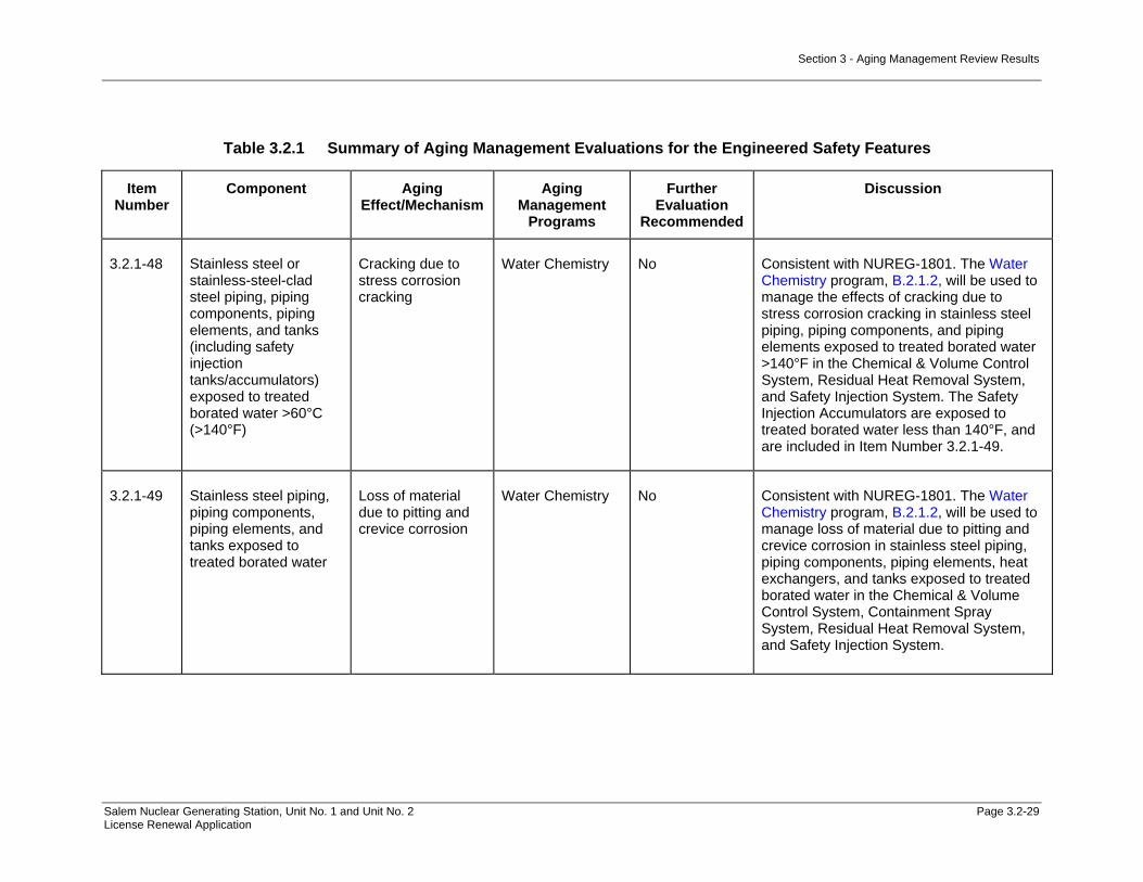
Section 3 - Aging Management Review Results
Salem Nuclear Generating Station, Unit No. 1 and Unit No. 2 Page 3.2-29 License Renewal Application
Table 3.2.1 Summary of Aging Management Evaluations for the Engineered Safety Features
Item Number
Component Aging Effect/Mechanism
Aging Management
Programs
Further Evaluation
Recommended
Discussion
3.2.1-48 Stainless steel or stainless-steel-clad steel piping, piping components, piping elements, and tanks (including safety injection tanks/accumulators) exposed to treated borated water >60°C (>140°F)
Cracking due to stress corrosion cracking
Water Chemistry No Consistent with NUREG-1801. The Water Chemistry program, B.2.1.2, will be used to manage the effects of cracking due to stress corrosion cracking in stainless steel piping, piping components, and piping elements exposed to treated borated water >140°F in the Chemical & Volume Control System, Residual Heat Removal System, and Safety Injection System. The Safety Injection Accumulators are exposed to treated borated water less than 140°F, and are included in Item Number 3.2.1-49.
3.2.1-49 Stainless steel piping, piping components, piping elements, and tanks exposed to treated borated water
Loss of material due to pitting and crevice corrosion
Water Chemistry No Consistent with NUREG-1801. The Water Chemistry program, B.2.1.2, will be used to manage loss of material due to pitting and crevice corrosion in stainless steel piping, piping components, piping elements, heat exchangers, and tanks exposed to treated borated water in the Chemical & Volume Control System, Containment Spray System, Residual Heat Removal System, and Safety Injection System.

Section 3 - Aging Management Review Results
Salem Nuclear Generating Station, Unit No. 1 and Unit No. 2 Page 3.2-30 License Renewal Application
Table 3.2.1 Summary of Aging Management Evaluations for the Engineered Safety Features
Item Number
Component Aging Effect/Mechanism
Aging Management
Programs
Further Evaluation
Recommended
Discussion
3.2.1-50 Aluminum piping, piping components, and piping elements exposed to air- indoor uncontrolled (internal/external)
None None NA - No AEM or AMP
Consistent with NUREG-1801.
3.2.1-51 Galvanized steel ducting exposed to air – indoor controlled (external)
None None NA - No AEM or AMP
Not Applicable. There is no galvanized steel ducting exposed to controlled indoor air in the Engineered Safety Features systems.
3.2.1-52 Glass piping elements exposed to air – indoor uncontrolled (external), lubricating oil, raw water, treated water, or treated borated water
None None NA - No AEM or AMP
Consistent with NUREG-1801.

Section 3 - Aging Management Review Results
Salem Nuclear Generating Station, Unit No. 1 and Unit No. 2 Page 3.2-31 License Renewal Application
Table 3.2.1 Summary of Aging Management Evaluations for the Engineered Safety Features
Item Number
Component Aging Effect/Mechanism
Aging Management
Programs
Further Evaluation
Recommended
Discussion
3.2.1-53 Stainless steel, copper alloy, and nickel alloy piping, piping components, and piping elements exposed to air – indoor uncontrolled (external)
None None NA - No AEM or AMP
Consistent with NUREG-1801.
3.2.1-54 Steel piping, piping components, and piping elements exposed to air – indoor controlled (external)
None None NA - No AEM or AMP
Not Applicable. There are no steel piping, piping components, and piping elements exposed to controlled indoor air in Engineered Safety Features systems. All indoor air environments at Salem are assumed to be uncontrolled for license renewal.
3.2.1-55 Steel and stainless steel piping, piping components, and piping elements in concrete
None None NA - No AEM or AMP
Not Applicable. There are no steel and stainless steel piping, piping components, and piping elements in concrete in the Engineered Safety Features systems.
3.2.1-56 Steel, stainless steel, and copper alloy piping, piping components, and piping elements exposed to gas
None None NA - No AEM or AMP
Consistent with NUREG-1801.

Section 3 - Aging Management Review Results
Salem Nuclear Generating Station, Unit No. 1 and Unit No. 2 Page 3.2-32 License Renewal Application
Table 3.2.1 Summary of Aging Management Evaluations for the Engineered Safety Features
Item Number
Component Aging Effect/Mechanism
Aging Management
Programs
Further Evaluation
Recommended
Discussion
3.2.1-57 Stainless steel and copper alloy <15% Zn piping, piping components, and piping elements exposed to air with borated water leakage
None None NA - No AEM or AMP
Consistent with NUREG-1801.
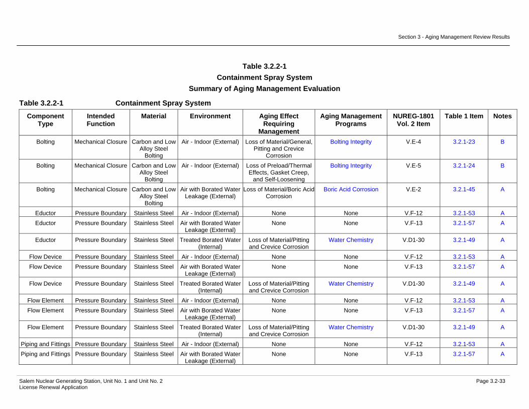
Section 3 - Aging Management Review Results
Salem Nuclear Generating Station, Unit No. 1 and Unit No. 2 Page 3.2-33 License Renewal Application
Table 3.2.2-1 Containment Spray System
Summary of Aging Management Evaluation
Table 3.2.2-1 Containment Spray System
Component Type
Intended Function
Material Environment Aging Effect Requiring
Management
Aging Management Programs
NUREG-1801 Vol. 2 Item
Table 1 Item Notes
Bolting Mechanical Closure Carbon and Low Alloy Steel
Bolting
Air - Indoor (External) Loss of Material/General, Pitting and Crevice
Corrosion
Bolting Integrity V.E-4 3.2.1-23 B
Bolting Mechanical Closure Carbon and Low Alloy Steel
Bolting
Air - Indoor (External) Loss of Preload/Thermal Effects, Gasket Creep,
and Self-Loosening
Bolting Integrity V.E-5 3.2.1-24 B
Bolting Mechanical Closure Carbon and Low Alloy Steel
Bolting
Air with Borated Water Leakage (External)
Loss of Material/Boric Acid Corrosion
Boric Acid Corrosion V.E-2 3.2.1-45 A
Eductor Pressure Boundary Stainless Steel Air - Indoor (External) None None V.F-12 3.2.1-53 A Eductor Pressure Boundary Stainless Steel Air with Borated Water
Leakage (External) None None V.F-13 3.2.1-57 A
Eductor Pressure Boundary Stainless Steel Treated Borated Water (Internal)
Loss of Material/Pitting and Crevice Corrosion
Water Chemistry V.D1-30 3.2.1-49 A
Flow Device Pressure Boundary Stainless Steel Air - Indoor (External) None None V.F-12 3.2.1-53 A Flow Device Pressure Boundary Stainless Steel Air with Borated Water
Leakage (External) None None V.F-13 3.2.1-57 A
Flow Device Pressure Boundary Stainless Steel Treated Borated Water (Internal)
Loss of Material/Pitting and Crevice Corrosion
Water Chemistry V.D1-30 3.2.1-49 A
Flow Element Pressure Boundary Stainless Steel Air - Indoor (External) None None V.F-12 3.2.1-53 A Flow Element Pressure Boundary Stainless Steel Air with Borated Water
Leakage (External) None None V.F-13 3.2.1-57 A
Flow Element Pressure Boundary Stainless Steel Treated Borated Water (Internal)
Loss of Material/Pitting and Crevice Corrosion
Water Chemistry V.D1-30 3.2.1-49 A
Piping and Fittings Pressure Boundary Stainless Steel Air - Indoor (External) None None V.F-12 3.2.1-53 A Piping and Fittings Pressure Boundary Stainless Steel Air with Borated Water
Leakage (External) None None V.F-13 3.2.1-57 A

Section 3 - Aging Management Review Results
Salem Nuclear Generating Station, Unit No. 1 and Unit No. 2 Page 3.2-34 License Renewal Application
Table 3.2.2-1 Containment Spray System (Continued)
Component Type
Intended Function
Material Environment Aging Effect Requiring
Management
Aging Management Programs
NUREG-1801 Vol. 2 Item
Table 1 Item Notes
Piping and Fittings Pressure Boundary Stainless Steel Air with Steam or Water Leakage (External)
Loss of Material/Pitting and Crevice Corrosion
Periodic Inspection VII.F3-1 3.3.1-27 E, 1
Piping and Fittings Pressure Boundary Stainless Steel Treated Borated Water (Internal)
Loss of Material/Pitting and Crevice Corrosion
Water Chemistry V.D1-30 3.2.1-49 A
Piping and Fittings Pressure Boundary Stainless Steel Treated Water (Internal) Loss of Material/Pitting and Crevice Corrosion
One-Time Inspection VII.E3-15 3.3.1-24 A
Piping and Fittings Pressure Boundary Stainless Steel Treated Water (Internal) Loss of Material/Pitting and Crevice Corrosion
Water Chemistry VII.E3-15 3.3.1-24 A
Pump Casing (Containment Spray Pumps)
Pressure Boundary Stainless Steel Air - Indoor (External) None None V.F-12 3.2.1-53 A
Pump Casing (Containment Spray Pumps)
Pressure Boundary Stainless Steel Air with Borated Water Leakage (External)
None None V.F-13 3.2.1-57 A
Pump Casing (Containment Spray Pumps)
Pressure Boundary Stainless Steel Treated Borated Water (Internal)
Loss of Material/Pitting and Crevice Corrosion
Water Chemistry V.A-27 3.2.1-49 A
Spray Nozzles Pressure Boundary Stainless Steel Air - Indoor (External) None None V.F-12 3.2.1-53 A Spray Nozzles Pressure Boundary Stainless Steel Air with Borated Water
Leakage (External) None None V.F-13 3.2.1-57 A
Spray Nozzles Pressure Boundary Stainless Steel Air/Gas - Wetted (Internal)
Loss of Material/Pitting and Crevice Corrosion
Periodic Inspection V.A-26 3.2.1-8 E, 1
Spray Nozzles Spray Stainless Steel Air - Indoor (External) None None V.F-12 3.2.1-53 A Spray Nozzles Spray Stainless Steel Air with Borated Water
Leakage (External) None None V.F-13 3.2.1-57 A
Spray Nozzles Spray Stainless Steel Air/Gas - Wetted (Internal)
Loss of Material/Pitting and Crevice Corrosion
Periodic Inspection V.A-26 3.2.1-8 E, 1
Strainer Body Pressure Boundary Stainless Steel Air - Indoor (External) None None V.F-12 3.2.1-53 A Strainer Body Pressure Boundary Stainless Steel Air with Borated Water
Leakage (External) None None V.F-13 3.2.1-57 A
Strainer Body Pressure Boundary Stainless Steel Treated Borated Water (Internal)
Loss of Material/Pitting and Crevice Corrosion
Water Chemistry V.D1-30 3.2.1-49 A

Section 3 - Aging Management Review Results
Salem Nuclear Generating Station, Unit No. 1 and Unit No. 2 Page 3.2-35 License Renewal Application
Table 3.2.2-1 Containment Spray System (Continued)
Component Type
Intended Function
Material Environment Aging Effect Requiring
Management
Aging Management Programs
NUREG-1801 Vol. 2 Item
Table 1 Item Notes
Tanks (Spray Additive Tank)
Pressure Boundary Stainless Steel Air - Indoor (External) None None V.F-12 3.2.1-53 C
Tanks (Spray Additive Tank)
Pressure Boundary Stainless Steel Air with Borated Water Leakage (External)
None None V.F-13 3.2.1-57 C
Tanks (Spray Additive Tank)
Pressure Boundary Stainless Steel Treated Water (Internal) Loss of Material/Pitting and Crevice Corrosion
One-Time Inspection VII.E3-15 3.3.1-24 C
Tanks (Spray Additive Tank)
Pressure Boundary Stainless Steel Treated Water (Internal) Loss of Material/Pitting and Crevice Corrosion
Water Chemistry VII.E3-15 3.3.1-24 C
Valve Body Pressure Boundary Stainless Steel Air - Indoor (External) None None V.F-12 3.2.1-53 A Valve Body Pressure Boundary Stainless Steel Air with Borated Water
Leakage (External) None None V.F-13 3.2.1-57 A
Valve Body Pressure Boundary Stainless Steel Air with Steam or Water Leakage (External)
Loss of Material/Pitting and Crevice Corrosion
Periodic Inspection VII.F3-1 3.3.1-27 E, 1
Valve Body Pressure Boundary Stainless Steel Air/Gas - Dry (Internal) None None V.F-15 3.2.1-56 A Valve Body Pressure Boundary Stainless Steel Treated Borated Water
(Internal) Loss of Material/Pitting and Crevice Corrosion
Water Chemistry V.D1-30 3.2.1-49 A
Valve Body Pressure Boundary Stainless Steel Treated Water (Internal) Loss of Material/Pitting and Crevice Corrosion
One-Time Inspection VII.E3-15 3.3.1-24 A
Valve Body Pressure Boundary Stainless Steel Treated Water (Internal) Loss of Material/Pitting and Crevice Corrosion
Water Chemistry VII.E3-15 3.3.1-24 A
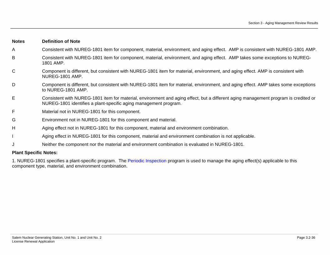
Section 3 - Aging Management Review Results
Salem Nuclear Generating Station, Unit No. 1 and Unit No. 2 Page 3.2-36 License Renewal Application
Notes Definition of Note
A Consistent with NUREG-1801 item for component, material, environment, and aging effect. AMP is consistent with NUREG-1801 AMP.
B Consistent with NUREG-1801 item for component, material, environment, and aging effect. AMP takes some exceptions to NUREG-1801 AMP.
C Component is different, but consistent with NUREG-1801 item for material, environment, and aging effect. AMP is consistent with NUREG-1801 AMP.
D Component is different, but consistent with NUREG-1801 item for material, environment, and aging effect. AMP takes some exceptions to NUREG-1801 AMP.
E Consistent with NUREG-1801 item for material, environment and aging effect, but a different aging management program is credited or NUREG-1801 identifies a plant-specific aging management program.
F Material not in NUREG-1801 for this component.
G Environment not in NUREG-1801 for this component and material.
H Aging effect not in NUREG-1801 for this component, material and environment combination.
I Aging effect in NUREG-1801 for this component, material and environment combination is not applicable.
J Neither the component nor the material and environment combination is evaluated in NUREG-1801.
Plant Specific Notes:
1. NUREG-1801 specifies a plant-specific program. The Periodic Inspection program is used to manage the aging effect(s) applicable to this component type, material, and environment combination.

Section 3 - Aging Management Review Results
Salem Nuclear Generating Station, Unit No. 1 and Unit No. 2 Page 3.2-37 License Renewal Application
Table 3.2.2-2 Residual Heat Removal System
Summary of Aging Management Evaluation
Table 3.2.2-2 Residual Heat Removal System
Component Type
Intended Function
Material Environment Aging Effect Requiring
Management
Aging Management Programs
NUREG-1801 Vol. 2 Item
Table 1 Item Notes
Bolting Mechanical Closure Carbon and Low Alloy Steel
Bolting
Air - Indoor (External) Loss of Material/General, Pitting and Crevice
Corrosion
Bolting Integrity V.E-4 3.2.1-23 B
Bolting Mechanical Closure Carbon and Low Alloy Steel
Bolting
Air - Indoor (External) Loss of Preload/Thermal Effects, Gasket Creep,
and Self-Loosening
Bolting Integrity V.E-5 3.2.1-24 B
Bolting Mechanical Closure Carbon and Low Alloy Steel
Bolting
Air with Borated Water Leakage (External)
Loss of Material/Boric Acid Corrosion
Boric Acid Corrosion V.E-2 3.2.1-45 A
Bolting Mechanical Closure Stainless Steel Bolting
Air - Indoor (External) Loss of Preload/Thermal Effects, Gasket Creep,
and Self-Loosening
Bolting Integrity IV.C2-8 3.1.1-52 B
Flow Element Pressure Boundary Stainless Steel Air - Indoor (External) None None V.F-12 3.2.1-53 A Flow Element Pressure Boundary Stainless Steel Air with Borated Water
Leakage (External) None None V.F-13 3.2.1-57 A
Flow Element Pressure Boundary Stainless Steel Treated Borated Water (Internal) > 140 F
Cracking/Stress Corrosion Cracking
Water Chemistry V.D1-31 3.2.1-48 A
Flow Element Pressure Boundary Stainless Steel Treated Borated Water (Internal) > 140 F
Loss of Material/Pitting and Crevice Corrosion
Water Chemistry V.D1-30 3.2.1-49 A
Heat Exchanger Components (RHR Mechanical Seal)
Evaluated with the Component Cooling
System
Not Applicable Not Applicable Not Applicable Not Applicable 1
Heat Exchanger Components
(Residual Heat Removal)
Evaluated with the Component Cooling
System
Not Applicable Not Applicable Not Applicable Not Applicable 1
Piping and Fittings Leakage Boundary Stainless Steel Air - Indoor (External) None None V.F-12 3.2.1-53 A

Section 3 - Aging Management Review Results
Salem Nuclear Generating Station, Unit No. 1 and Unit No. 2 Page 3.2-38 License Renewal Application
Table 3.2.2-2 Residual Heat Removal System (Continued)
Component Type
Intended Function
Material Environment Aging Effect Requiring
Management
Aging Management Programs
NUREG-1801 Vol. 2 Item
Table 1 Item Notes
Piping and Fittings Leakage Boundary Stainless Steel Air with Borated Water Leakage (External)
None None V.F-13 3.2.1-57 A
Piping and Fittings Leakage Boundary Stainless Steel Treated Borated Water (Internal) > 140 F
Cracking/Stress Corrosion Cracking
Water Chemistry V.D1-31 3.2.1-48 A
Piping and Fittings Leakage Boundary Stainless Steel Treated Borated Water (Internal) > 140 F
Loss of Material/Pitting and Crevice Corrosion
Water Chemistry V.D1-30 3.2.1-49 A
Piping and Fittings Pressure Boundary Stainless Steel Air - Indoor (External) None None V.F-12 3.2.1-53 A Piping and Fittings Pressure Boundary Stainless Steel Air with Borated Water
Leakage (External) None None V.F-13 3.2.1-57 A
Piping and Fittings Pressure Boundary Stainless Steel Air with Steam or Water Leakage (External)
Loss of Material/Pitting and Crevice Corrosion
Periodic Inspection VII.F3-1 3.3.1-27 E, 2
Piping and Fittings Pressure Boundary Stainless Steel Treated Borated Water (Internal) > 140 F
Cracking/Stress Corrosion Cracking
Water Chemistry V.D1-31 3.2.1-48 A
Piping and Fittings Pressure Boundary Stainless Steel Treated Borated Water (Internal) > 140 F
Cumulative Fatigue Damage/Fatigue
TLAA V.D1-27 3.2.1-1 A, 3
Piping and Fittings Pressure Boundary Stainless Steel Treated Borated Water (Internal) > 140 F
Loss of Material/Pitting and Crevice Corrosion
Water Chemistry V.D1-30 3.2.1-49 A
Pump Casing (Letdown Booster
Pump)
Leakage Boundary Stainless Steel Air - Indoor (External) None None V.F-12 3.2.1-53 A
Pump Casing (Letdown Booster
Pump)
Leakage Boundary Stainless Steel Air with Borated Water Leakage (External)
None None V.F-13 3.2.1-57 A
Pump Casing (Letdown Booster
Pump)
Leakage Boundary Stainless Steel Treated Borated Water (Internal) > 140 F
Cracking/Stress Corrosion Cracking
Water Chemistry V.D1-31 3.2.1-48 A
Pump Casing (Letdown Booster
Pump)
Leakage Boundary Stainless Steel Treated Borated Water (Internal) > 140 F
Loss of Material/Pitting and Crevice Corrosion
Water Chemistry V.D1-30 3.2.1-49 A
Pump Casing (Residual Heat
Removal)
Pressure Boundary Stainless Steel Air - Indoor (External) None None V.F-12 3.2.1-53 A

Section 3 - Aging Management Review Results
Salem Nuclear Generating Station, Unit No. 1 and Unit No. 2 Page 3.2-39 License Renewal Application
Table 3.2.2-2 Residual Heat Removal System (Continued)
Component Type
Intended Function
Material Environment Aging Effect Requiring
Management
Aging Management Programs
NUREG-1801 Vol. 2 Item
Table 1 Item Notes
Pump Casing (Residual Heat
Removal)
Pressure Boundary Stainless Steel Air with Borated Water Leakage (External)
None None V.F-13 3.2.1-57 A
Pump Casing (Residual Heat
Removal)
Pressure Boundary Stainless Steel Treated Borated Water (Internal) > 140 F
Cracking/Stress Corrosion Cracking
Water Chemistry V.D1-31 3.2.1-48 A
Pump Casing (Residual Heat
Removal)
Pressure Boundary Stainless Steel Treated Borated Water (Internal) > 140 F
Loss of Material/Pitting and Crevice Corrosion
Water Chemistry V.D1-30 3.2.1-49 A
Restricting Orifices Leakage Boundary Stainless Steel Air - Indoor (External) None None V.F-12 3.2.1-53 A Restricting Orifices Leakage Boundary Stainless Steel Air with Borated Water
Leakage (External) None None V.F-13 3.2.1-57 A
Restricting Orifices Leakage Boundary Stainless Steel Treated Borated Water (Internal) > 140 F
Cracking/Stress Corrosion Cracking
Water Chemistry V.D1-31 3.2.1-48 A
Restricting Orifices Leakage Boundary Stainless Steel Treated Borated Water (Internal) > 140 F
Loss of Material/Pitting and Crevice Corrosion
Water Chemistry V.D1-30 3.2.1-49 A
Restricting Orifices Pressure Boundary Stainless Steel Air - Indoor (External) None None V.F-12 3.2.1-53 A Restricting Orifices Pressure Boundary Stainless Steel Air with Borated Water
Leakage (External) None None V.F-13 3.2.1-57 A
Restricting Orifices Pressure Boundary Stainless Steel Treated Borated Water (Internal) > 140 F
Cracking/Stress Corrosion Cracking
Water Chemistry V.D1-31 3.2.1-48 A
Restricting Orifices Pressure Boundary Stainless Steel Treated Borated Water (Internal) > 140 F
Loss of Material/Pitting and Crevice Corrosion
Water Chemistry V.D1-30 3.2.1-49 A
Restricting Orifices Throttle Stainless Steel Air - Indoor (External) None None V.F-12 3.2.1-53 A Restricting Orifices Throttle Stainless Steel Air with Borated Water
Leakage (External) None None V.F-13 3.2.1-57 A
Restricting Orifices Throttle Stainless Steel Treated Borated Water (Internal) > 140 F
Cracking/Stress Corrosion Cracking
Water Chemistry V.D1-31 3.2.1-48 A
Restricting Orifices Throttle Stainless Steel Treated Borated Water (Internal) > 140 F
Loss of Material/Pitting and Crevice Corrosion
Water Chemistry V.D1-30 3.2.1-49 A
Strainer Body Pressure Boundary Stainless Steel Air - Indoor (External) None None V.F-12 3.2.1-53 A Strainer Body Pressure Boundary Stainless Steel Air with Borated Water
Leakage (External) None None V.F-13 3.2.1-57 A
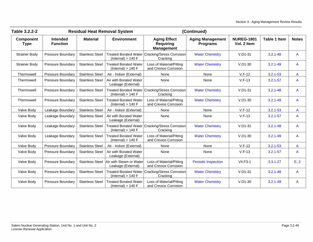
Section 3 - Aging Management Review Results
Salem Nuclear Generating Station, Unit No. 1 and Unit No. 2 Page 3.2-40 License Renewal Application
Table 3.2.2-2 Residual Heat Removal System (Continued)
Component Type
Intended Function
Material Environment Aging Effect Requiring
Management
Aging Management Programs
NUREG-1801 Vol. 2 Item
Table 1 Item Notes
Strainer Body Pressure Boundary Stainless Steel Treated Borated Water (Internal) > 140 F
Cracking/Stress Corrosion Cracking
Water Chemistry V.D1-31 3.2.1-48 A
Strainer Body Pressure Boundary Stainless Steel Treated Borated Water (Internal) > 140 F
Loss of Material/Pitting and Crevice Corrosion
Water Chemistry V.D1-30 3.2.1-49 A
Thermowell Pressure Boundary Stainless Steel Air - Indoor (External) None None V.F-12 3.2.1-53 A Thermowell Pressure Boundary Stainless Steel Air with Borated Water
Leakage (External) None None V.F-13 3.2.1-57 A
Thermowell Pressure Boundary Stainless Steel Treated Borated Water (Internal) > 140 F
Cracking/Stress Corrosion Cracking
Water Chemistry V.D1-31 3.2.1-48 A
Thermowell Pressure Boundary Stainless Steel Treated Borated Water (Internal) > 140 F
Loss of Material/Pitting and Crevice Corrosion
Water Chemistry V.D1-30 3.2.1-49 A
Valve Body Leakage Boundary Stainless Steel Air - Indoor (External) None None V.F-12 3.2.1-53 A Valve Body Leakage Boundary Stainless Steel Air with Borated Water
Leakage (External) None None V.F-13 3.2.1-57 A
Valve Body Leakage Boundary Stainless Steel Treated Borated Water (Internal) > 140 F
Cracking/Stress Corrosion Cracking
Water Chemistry V.D1-31 3.2.1-48 A
Valve Body Leakage Boundary Stainless Steel Treated Borated Water (Internal) > 140 F
Loss of Material/Pitting and Crevice Corrosion
Water Chemistry V.D1-30 3.2.1-49 A
Valve Body Pressure Boundary Stainless Steel Air - Indoor (External) None None V.F-12 3.2.1-53 A Valve Body Pressure Boundary Stainless Steel Air with Borated Water
Leakage (External) None None V.F-13 3.2.1-57 A
Valve Body Pressure Boundary Stainless Steel Air with Steam or Water Leakage (External)
Loss of Material/Pitting and Crevice Corrosion
Periodic Inspection VII.F3-1 3.3.1-27 E, 2
Valve Body Pressure Boundary Stainless Steel Treated Borated Water (Internal) > 140 F
Cracking/Stress Corrosion Cracking
Water Chemistry V.D1-31 3.2.1-48 A
Valve Body Pressure Boundary Stainless Steel Treated Borated Water (Internal) > 140 F
Loss of Material/Pitting and Crevice Corrosion
Water Chemistry V.D1-30 3.2.1-49 A

Section 3 - Aging Management Review Results
Salem Nuclear Generating Station, Unit No. 1 and Unit No. 2 Page 3.2-41 License Renewal Application
Notes Definition of Note
A Consistent with NUREG-1801 item for component, material, environment, and aging effect. AMP is consistent with NUREG-1801 AMP.
B Consistent with NUREG-1801 item for component, material, environment, and aging effect. AMP takes some exceptions to NUREG-1801 AMP.
C Component is different, but consistent with NUREG-1801 item for material, environment, and aging effect. AMP is consistent with NUREG-1801 AMP.
D Component is different, but consistent with NUREG-1801 item for material, environment, and aging effect. AMP takes some exceptions to NUREG-1801 AMP.
E Consistent with NUREG-1801 item for material, environment and aging effect, but a different aging management program is credited or NUREG-1801 identifies a plant-specific aging management program.
F Material not in NUREG-1801 for this component.
G Environment not in NUREG-1801 for this component and material.
H Aging effect not in NUREG-1801 for this component, material and environment combination.
I Aging effect in NUREG-1801 for this component, material and environment combination is not applicable.
J Neither the component nor the material and environment combination is evaluated in NUREG-1801.
Plant Specific Notes:
1. Aging management for this component is evaluated with the Component Cooling System.
2. NUREG-1801 specifies a plant-specific program. The Periodic Inspection program is used to manage the aging effect(s) applicable to this component type, material, and environment combination. Loss of material due to pitting and crevice corrosion on the external surface of this component type has occurred at Salem Nuclear Generating Station based on site-specific operating experience reviews.
3. The TLAA designation in the Aging Management Program column indicates fatigue of this component is evaluated in Section 4.3.
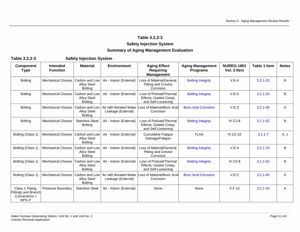
Section 3 - Aging Management Review Results
Salem Nuclear Generating Station, Unit No. 1 and Unit No. 2 Page 3.2-42 License Renewal Application
Table 3.2.2-3 Safety Injection System
Summary of Aging Management Evaluation
Table 3.2.2-3 Safety Injection System
Component Type
Intended Function
Material Environment Aging Effect Requiring
Management
Aging Management Programs
NUREG-1801 Vol. 2 Item
Table 1 Item Notes
Bolting Mechanical Closure Carbon and Low Alloy Steel
Bolting
Air - Indoor (External) Loss of Material/General, Pitting and Crevice
Corrosion
Bolting Integrity V.E-4 3.2.1-23 B
Bolting Mechanical Closure Carbon and Low Alloy Steel
Bolting
Air - Indoor (External) Loss of Preload/Thermal Effects, Gasket Creep,
and Self-Loosening
Bolting Integrity V.E-5 3.2.1-24 B
Bolting Mechanical Closure Carbon and Low Alloy Steel
Bolting
Air with Borated Water Leakage (External)
Loss of Material/Boric Acid Corrosion
Boric Acid Corrosion V.E-2 3.2.1-45 A
Bolting Mechanical Closure Stainless Steel Bolting
Air - Indoor (External) Loss of Preload/Thermal Effects, Gasket Creep,
and Self-Loosening
Bolting Integrity IV.C2-8 3.1.1-52 B
Bolting (Class 1) Mechanical Closure Carbon and Low Alloy Steel
Bolting
Air - Indoor (External) Cumulative Fatigue Damage/Fatigue
TLAA IV.C2-10 3.1.1-7 A, 1
Bolting (Class 1) Mechanical Closure Carbon and Low Alloy Steel
Bolting
Air - Indoor (External) Loss of Material/General, Pitting and Crevice
Corrosion
Bolting Integrity V.E-4 3.2.1-23 B
Bolting (Class 1) Mechanical Closure Carbon and Low Alloy Steel
Bolting
Air - Indoor (External) Loss of Preload/Thermal Effects, Gasket Creep,
and Self-Loosening
Bolting Integrity IV.C2-8 3.1.1-52 B
Bolting (Class 1) Mechanical Closure Carbon and Low Alloy Steel
Bolting
Air with Borated Water Leakage (External)
Loss of Material/Boric Acid Corrosion
Boric Acid Corrosion V.E-2 3.2.1-45 A
Class 1 Piping, Fittings and Branch
Connections < NPS 4"
Pressure Boundary Stainless Steel Air - Indoor (External) None None V.F-12 3.2.1-53 A
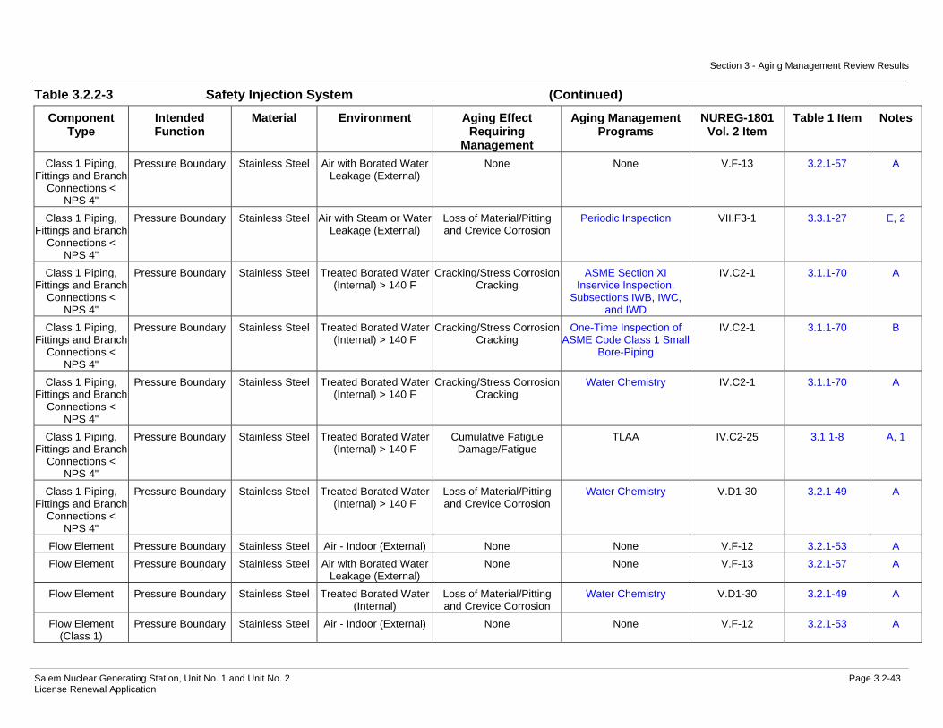
Section 3 - Aging Management Review Results
Salem Nuclear Generating Station, Unit No. 1 and Unit No. 2 Page 3.2-43 License Renewal Application
Table 3.2.2-3 Safety Injection System (Continued)
Component Type
Intended Function
Material Environment Aging Effect Requiring
Management
Aging Management Programs
NUREG-1801 Vol. 2 Item
Table 1 Item Notes
Class 1 Piping, Fittings and Branch
Connections < NPS 4"
Pressure Boundary Stainless Steel Air with Borated Water Leakage (External)
None None V.F-13 3.2.1-57 A
Class 1 Piping, Fittings and Branch
Connections < NPS 4"
Pressure Boundary Stainless Steel Air with Steam or Water Leakage (External)
Loss of Material/Pitting and Crevice Corrosion
Periodic Inspection VII.F3-1 3.3.1-27 E, 2
Class 1 Piping, Fittings and Branch
Connections < NPS 4"
Pressure Boundary Stainless Steel Treated Borated Water (Internal) > 140 F
Cracking/Stress Corrosion Cracking
ASME Section XI Inservice Inspection,
Subsections IWB, IWC, and IWD
IV.C2-1 3.1.1-70 A
Class 1 Piping, Fittings and Branch
Connections < NPS 4"
Pressure Boundary Stainless Steel Treated Borated Water (Internal) > 140 F
Cracking/Stress Corrosion Cracking
One-Time Inspection of ASME Code Class 1 Small
Bore-Piping
IV.C2-1 3.1.1-70 B
Class 1 Piping, Fittings and Branch
Connections < NPS 4"
Pressure Boundary Stainless Steel Treated Borated Water (Internal) > 140 F
Cracking/Stress Corrosion Cracking
Water Chemistry IV.C2-1 3.1.1-70 A
Class 1 Piping, Fittings and Branch
Connections < NPS 4"
Pressure Boundary Stainless Steel Treated Borated Water (Internal) > 140 F
Cumulative Fatigue Damage/Fatigue
TLAA IV.C2-25 3.1.1-8 A, 1
Class 1 Piping, Fittings and Branch
Connections < NPS 4"
Pressure Boundary Stainless Steel Treated Borated Water (Internal) > 140 F
Loss of Material/Pitting and Crevice Corrosion
Water Chemistry V.D1-30 3.2.1-49 A
Flow Element Pressure Boundary Stainless Steel Air - Indoor (External) None None V.F-12 3.2.1-53 A Flow Element Pressure Boundary Stainless Steel Air with Borated Water
Leakage (External) None None V.F-13 3.2.1-57 A
Flow Element Pressure Boundary Stainless Steel Treated Borated Water (Internal)
Loss of Material/Pitting and Crevice Corrosion
Water Chemistry V.D1-30 3.2.1-49 A
Flow Element (Class 1)
Pressure Boundary Stainless Steel Air - Indoor (External) None None V.F-12 3.2.1-53 A

Section 3 - Aging Management Review Results
Salem Nuclear Generating Station, Unit No. 1 and Unit No. 2 Page 3.2-44 License Renewal Application
Table 3.2.2-3 Safety Injection System (Continued)
Component Type
Intended Function
Material Environment Aging Effect Requiring
Management
Aging Management Programs
NUREG-1801 Vol. 2 Item
Table 1 Item Notes
Flow Element (Class 1)
Pressure Boundary Stainless Steel Air with Borated Water Leakage (External)
None None V.F-13 3.2.1-57 A
Flow Element (Class 1)
Pressure Boundary Stainless Steel Treated Borated Water (Internal) > 140 F
Cracking/Stress Corrosion Cracking
ASME Section XI Inservice Inspection,
Subsections IWB, IWC, and IWD
IV.C2-2 3.1.1-68 A
Flow Element (Class 1)
Pressure Boundary Stainless Steel Treated Borated Water (Internal) > 140 F
Cracking/Stress Corrosion Cracking
Water Chemistry IV.C2-2 3.1.1-68 A
Flow Element (Class 1)
Pressure Boundary Stainless Steel Treated Borated Water (Internal) > 140 F
Loss of Material/Pitting and Crevice Corrosion
Water Chemistry IV.C2-15 3.1.1-83 A
Heat Exchanger Components
(Refueling Water Storage Tank)
Pressure Boundary Stainless Steel (Shellside
Components)
Air - Indoor (External) None None V.F-12 3.2.1-53 C
Heat Exchanger Components
(Refueling Water Storage Tank)
Pressure Boundary Stainless Steel (Shellside
Components)
Air with Borated Water Leakage (External)
None None V.F-13 3.2.1-57 C
Heat Exchanger Components
(Refueling Water Storage Tank)
Pressure Boundary Stainless Steel (Shellside
Components)
Treated Borated Water (Internal)
Loss of Material/Pitting and Crevice Corrosion
Water Chemistry V.D1-30 3.2.1-49 C
Heat Exchanger Components
(Refueling Water Storage Tank)
Pressure Boundary Stainless Steel (Tube Sheet)
Closed Cycle Cooling Water (Internal) > 140 F
Cracking/Stress Corrosion Cracking
Closed-Cycle Cooling Water System
V.D1-23 3.2.1-25 D
Heat Exchanger Components
(Refueling Water Storage Tank)
Pressure Boundary Stainless Steel (Tube Sheet)
Closed Cycle Cooling Water (Internal) > 140 F
Loss of Material/Pitting and Crevice Corrosion
Closed-Cycle Cooling Water System
V.D1-4 3.2.1-28 B
Heat Exchanger Components
(Refueling Water Storage Tank)
Pressure Boundary Stainless Steel (Tube Sheet)
Treated Borated Water (External)
Loss of Material/Pitting and Crevice Corrosion
Water Chemistry V.D1-30 3.2.1-49 C

Section 3 - Aging Management Review Results
Salem Nuclear Generating Station, Unit No. 1 and Unit No. 2 Page 3.2-45 License Renewal Application
Table 3.2.2-3 Safety Injection System (Continued)
Component Type
Intended Function
Material Environment Aging Effect Requiring
Management
Aging Management Programs
NUREG-1801 Vol. 2 Item
Table 1 Item Notes
Heat Exchanger Components
(Refueling Water Storage Tank)
Pressure Boundary Stainless Steel (Tubes)
Closed Cycle Cooling Water (Internal) > 140 F
Cracking/Stress Corrosion Cracking
Closed-Cycle Cooling Water System
V.D1-23 3.2.1-25 D
Heat Exchanger Components
(Refueling Water Storage Tank)
Pressure Boundary Stainless Steel (Tubes)
Closed Cycle Cooling Water (Internal) > 140 F
Loss of Material/Pitting and Crevice Corrosion
Closed-Cycle Cooling Water System
V.D1-4 3.2.1-28 B
Heat Exchanger Components
(Refueling Water Storage Tank)
Pressure Boundary Stainless Steel (Tubes)
Treated Borated Water (External)
Loss of Material/Pitting and Crevice Corrosion
Water Chemistry V.D1-30 3.2.1-49 C
Heat Exchanger Components
(Refueling Water Storage Tank)
Pressure Boundary Stainless Steel (Tubeside
Components)
Air - Indoor (External) None None V.F-12 3.2.1-53 C
Heat Exchanger Components
(Refueling Water Storage Tank)
Pressure Boundary Stainless Steel (Tubeside
Components)
Air with Borated Water Leakage (External)
None None V.F-13 3.2.1-57 C
Heat Exchanger Components
(Refueling Water Storage Tank)
Pressure Boundary Stainless Steel (Tubeside
Components)
Closed Cycle Cooling Water (Internal) > 140 F
Cracking/Stress Corrosion Cracking
Closed-Cycle Cooling Water System
V.D1-23 3.2.1-25 D
Heat Exchanger Components
(Refueling Water Storage Tank)
Pressure Boundary Stainless Steel (Tubeside
Components)
Closed Cycle Cooling Water (Internal) > 140 F
Loss of Material/Pitting and Crevice Corrosion
Closed-Cycle Cooling Water System
V.D1-4 3.2.1-28 B
Heat Exchanger Components
(Safety Injection Pump Lube Oil
Coolers)
Evaluated with the Service Water
System
Not Applicable Not Applicable Not Applicable Not Applicable 3
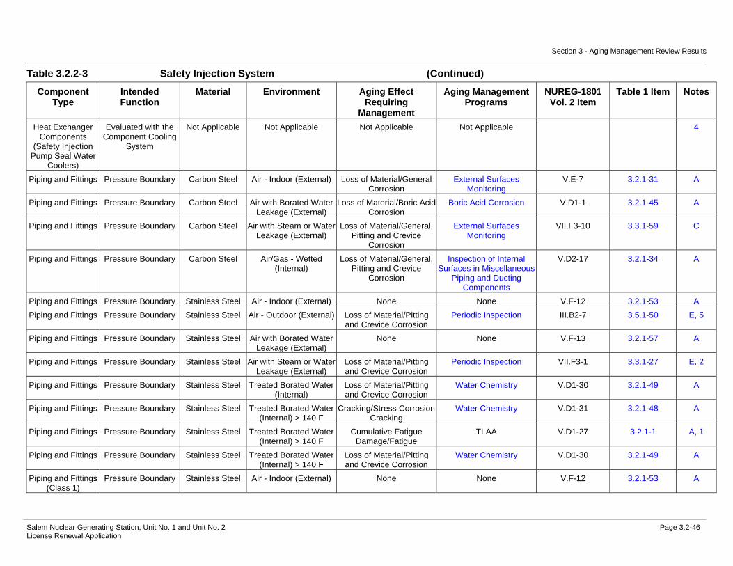
Section 3 - Aging Management Review Results
Salem Nuclear Generating Station, Unit No. 1 and Unit No. 2 Page 3.2-46 License Renewal Application
Table 3.2.2-3 Safety Injection System (Continued)
Component Type
Intended Function
Material Environment Aging Effect Requiring
Management
Aging Management Programs
NUREG-1801 Vol. 2 Item
Table 1 Item Notes
Heat Exchanger Components
(Safety Injection Pump Seal Water
Coolers)
Evaluated with the Component Cooling
System
Not Applicable Not Applicable Not Applicable Not Applicable 4
Piping and Fittings Pressure Boundary Carbon Steel Air - Indoor (External) Loss of Material/General Corrosion
External Surfaces Monitoring
V.E-7 3.2.1-31 A
Piping and Fittings Pressure Boundary Carbon Steel Air with Borated Water Leakage (External)
Loss of Material/Boric Acid Corrosion
Boric Acid Corrosion V.D1-1 3.2.1-45 A
Piping and Fittings Pressure Boundary Carbon Steel Air with Steam or Water Leakage (External)
Loss of Material/General, Pitting and Crevice
Corrosion
External Surfaces Monitoring
VII.F3-10 3.3.1-59 C
Piping and Fittings Pressure Boundary Carbon Steel Air/Gas - Wetted (Internal)
Loss of Material/General, Pitting and Crevice
Corrosion
Inspection of Internal Surfaces in Miscellaneous
Piping and Ducting Components
V.D2-17 3.2.1-34 A
Piping and Fittings Pressure Boundary Stainless Steel Air - Indoor (External) None None V.F-12 3.2.1-53 A Piping and Fittings Pressure Boundary Stainless Steel Air - Outdoor (External) Loss of Material/Pitting
and Crevice Corrosion Periodic Inspection III.B2-7 3.5.1-50 E, 5
Piping and Fittings Pressure Boundary Stainless Steel Air with Borated Water Leakage (External)
None None V.F-13 3.2.1-57 A
Piping and Fittings Pressure Boundary Stainless Steel Air with Steam or Water Leakage (External)
Loss of Material/Pitting and Crevice Corrosion
Periodic Inspection VII.F3-1 3.3.1-27 E, 2
Piping and Fittings Pressure Boundary Stainless Steel Treated Borated Water (Internal)
Loss of Material/Pitting and Crevice Corrosion
Water Chemistry V.D1-30 3.2.1-49 A
Piping and Fittings Pressure Boundary Stainless Steel Treated Borated Water (Internal) > 140 F
Cracking/Stress Corrosion Cracking
Water Chemistry V.D1-31 3.2.1-48 A
Piping and Fittings Pressure Boundary Stainless Steel Treated Borated Water (Internal) > 140 F
Cumulative Fatigue Damage/Fatigue
TLAA V.D1-27 3.2.1-1 A, 1
Piping and Fittings Pressure Boundary Stainless Steel Treated Borated Water (Internal) > 140 F
Loss of Material/Pitting and Crevice Corrosion
Water Chemistry V.D1-30 3.2.1-49 A
Piping and Fittings (Class 1)
Pressure Boundary Stainless Steel Air - Indoor (External) None None V.F-12 3.2.1-53 A

Section 3 - Aging Management Review Results
Salem Nuclear Generating Station, Unit No. 1 and Unit No. 2 Page 3.2-47 License Renewal Application
Table 3.2.2-3 Safety Injection System (Continued)
Component Type
Intended Function
Material Environment Aging Effect Requiring
Management
Aging Management Programs
NUREG-1801 Vol. 2 Item
Table 1 Item Notes
Piping and Fittings (Class 1)
Pressure Boundary Stainless Steel Air with Borated Water Leakage (External)
None None V.F-13 3.2.1-57 A
Piping and Fittings (Class 1)
Pressure Boundary Stainless Steel Air with Steam or Water Leakage (External)
Loss of Material/Pitting and Crevice Corrosion
Periodic Inspection VII.F3-1 3.3.1-27 E, 2
Piping and Fittings (Class 1)
Pressure Boundary Stainless Steel Treated Borated Water (Internal) > 140 F
Cracking/Stress Corrosion Cracking
ASME Section XI Inservice Inspection,
Subsections IWB, IWC, and IWD
IV.C2-2 3.1.1-68 A
Piping and Fittings (Class 1)
Pressure Boundary Stainless Steel Treated Borated Water (Internal) > 140 F
Cracking/Stress Corrosion Cracking
Water Chemistry IV.C2-2 3.1.1-68 A
Piping and Fittings (Class 1)
Pressure Boundary Stainless Steel Treated Borated Water (Internal) > 140 F
Cumulative Fatigue Damage/Fatigue
TLAA IV.C2-25 3.1.1-8 A, 1
Piping and Fittings (Class 1)
Pressure Boundary Stainless Steel Treated Borated Water (Internal) > 140 F
Loss of Material/Pitting and Crevice Corrosion
Water Chemistry IV.C2-15 3.1.1-83 A
Pump Casing (RWST Heating
Circulator)
Pressure Boundary Stainless Steel Air - Indoor (External) None None V.F-12 3.2.1-53 A
Pump Casing (RWST Heating
Circulator)
Pressure Boundary Stainless Steel Air with Borated Water Leakage (External)
None None V.F-13 3.2.1-57 A
Pump Casing (RWST Heating
Circulator)
Pressure Boundary Stainless Steel Treated Borated Water (Internal)
Loss of Material/Pitting and Crevice Corrosion
Water Chemistry V.D1-30 3.2.1-49 A
Pump Casing (Safety Injection)
Pressure Boundary Stainless Steel Air - Indoor (External) None None V.F-12 3.2.1-53 A
Pump Casing (Safety Injection)
Pressure Boundary Stainless Steel Air with Borated Water Leakage (External)
None None V.F-13 3.2.1-57 A
Pump Casing (Safety Injection)
Pressure Boundary Stainless Steel Treated Borated Water (Internal)
Loss of Material/Pitting and Crevice Corrosion
Water Chemistry V.D1-30 3.2.1-49 A
Restricting Orifices Pressure Boundary Stainless Steel Air - Indoor (External) None None V.F-12 3.2.1-53 A Restricting Orifices Pressure Boundary Stainless Steel Air with Borated Water
Leakage (External) None None V.F-13 3.2.1-57 A
Restricting Orifices Pressure Boundary Stainless Steel Treated Borated Water (Internal)
Loss of Material/Pitting and Crevice Corrosion
Water Chemistry V.D1-30 3.2.1-49 A

Section 3 - Aging Management Review Results
Salem Nuclear Generating Station, Unit No. 1 and Unit No. 2 Page 3.2-48 License Renewal Application
Table 3.2.2-3 Safety Injection System (Continued)
Component Type
Intended Function
Material Environment Aging Effect Requiring
Management
Aging Management Programs
NUREG-1801 Vol. 2 Item
Table 1 Item Notes
Restricting Orifices Throttle Stainless Steel Air - Indoor (External) None None V.F-12 3.2.1-53 A Restricting Orifices Throttle Stainless Steel Air with Borated Water
Leakage (External) None None V.F-13 3.2.1-57 A
Restricting Orifices Throttle Stainless Steel Treated Borated Water (Internal)
Loss of Material/Erosion Water Chemistry V.D1-14 3.2.1-12 E, 6
Restricting Orifices Throttle Stainless Steel Treated Borated Water (Internal)
Loss of Material/Pitting and Crevice Corrosion
Water Chemistry V.D1-30 3.2.1-49 A
Restricting Orifices (Class 1)
Pressure Boundary Stainless Steel Air - Indoor (External) None None V.F-12 3.2.1-53 A
Restricting Orifices (Class 1)
Pressure Boundary Stainless Steel Air with Borated Water Leakage (External)
None None V.F-13 3.2.1-57 A
Restricting Orifices (Class 1)
Pressure Boundary Stainless Steel Treated Borated Water (Internal) > 140 F
Cracking/Stress Corrosion Cracking
ASME Section XI Inservice Inspection,
Subsections IWB, IWC, and IWD
IV.C2-2 3.1.1-68 A
Restricting Orifices (Class 1)
Pressure Boundary Stainless Steel Treated Borated Water (Internal) > 140 F
Cracking/Stress Corrosion Cracking
Water Chemistry IV.C2-2 3.1.1-68 A
Restricting Orifices (Class 1)
Pressure Boundary Stainless Steel Treated Borated Water (Internal) > 140 F
Loss of Material/Pitting and Crevice Corrosion
Water Chemistry IV.C2-15 3.1.1-83 A
Restricting Orifices (Class 1)
Throttle Stainless Steel Air - Indoor (External) None None V.F-12 3.2.1-53 A
Restricting Orifices (Class 1)
Throttle Stainless Steel Air with Borated Water Leakage (External)
None None V.F-13 3.2.1-57 A
Restricting Orifices (Class 1)
Throttle Stainless Steel Treated Borated Water (Internal)
Loss of Material/Erosion Water Chemistry V.D1-14 3.2.1-12 E, 6
Restricting Orifices (Class 1)
Throttle Stainless Steel Treated Borated Water (Internal)
Loss of Material/Pitting and Crevice Corrosion
Water Chemistry V.D1-30 3.2.1-49 A
Strainer Body Pressure Boundary Stainless Steel Air - Indoor (External) None None V.F-12 3.2.1-53 A Strainer Body Pressure Boundary Stainless Steel Air with Borated Water
Leakage (External) None None V.F-13 3.2.1-57 A
Strainer Body Pressure Boundary Stainless Steel Treated Borated Water (Internal)
Loss of Material/Pitting and Crevice Corrosion
Water Chemistry V.D1-30 3.2.1-49 A

Section 3 - Aging Management Review Results
Salem Nuclear Generating Station, Unit No. 1 and Unit No. 2 Page 3.2-49 License Renewal Application
Table 3.2.2-3 Safety Injection System (Continued)
Component Type
Intended Function
Material Environment Aging Effect Requiring
Management
Aging Management Programs
NUREG-1801 Vol. 2 Item
Table 1 Item Notes
Tanks (Boron Injection Tank)
Pressure Boundary Carbon or Low Alloy Steel with Stainless Steel
Cladding
Air - Indoor (External) Loss of Material/General Corrosion
External Surfaces Monitoring
V.E-7 3.2.1-31 A
Tanks (Boron Injection Tank)
Pressure Boundary Carbon or Low Alloy Steel with Stainless Steel
Cladding
Air with Borated Water Leakage (External)
Loss of Material/Boric Acid Corrosion
Boric Acid Corrosion V.E-9 3.2.1-45 A
Tanks (Boron Injection Tank)
Pressure Boundary Carbon or Low Alloy Steel with Stainless Steel
Cladding
Treated Borated Water (Internal)
Loss of Material/Pitting and Crevice Corrosion
Water Chemistry V.D1-30 3.2.1-49 A
Tanks (Refueling Water Storage
Tank)
Pressure Boundary Stainless Steel Air - Outdoor (External) Loss of Material/Pitting and Crevice Corrosion
Aboveground Non-Steel Tanks
III.B2-7 3.5.1-50 E, 5
Tanks (Refueling Water Storage
Tank)
Pressure Boundary Stainless Steel Soil (External) Loss of Material/Pitting, Crevice, and
Microbiologically Influenced Corrosion
Aboveground Non-Steel Tanks
G, 7
Tanks (Refueling Water Storage
Tank)
Pressure Boundary Stainless Steel Treated Borated Water (Internal)
Loss of Material/Pitting and Crevice Corrosion
Water Chemistry V.D1-30 3.2.1-49 A
Tanks (Safety Injection
Accumulators)
Pressure Boundary Carbon or Low Alloy Steel with Stainless Steel
Cladding
Air - Indoor (External) Loss of Material/General Corrosion
External Surfaces Monitoring
V.E-7 3.2.1-31 A
Tanks (Safety Injection
Accumulators)
Pressure Boundary Carbon or Low Alloy Steel with Stainless Steel
Cladding
Air with Borated Water Leakage (External)
Loss of Material/Boric Acid Corrosion
Boric Acid Corrosion V.E-9 3.2.1-45 A
Tanks (Safety Injection
Accumulators)
Pressure Boundary Carbon or Low Alloy Steel with Stainless Steel
Cladding
Treated Borated Water (Internal)
Loss of Material/Pitting and Crevice Corrosion
Water Chemistry V.D1-30 3.2.1-49 A
Valve Body Pressure Boundary Carbon Steel Air - Indoor (External) Loss of Material/General Corrosion
External Surfaces Monitoring
V.E-7 3.2.1-31 A

Section 3 - Aging Management Review Results
Salem Nuclear Generating Station, Unit No. 1 and Unit No. 2 Page 3.2-50 License Renewal Application
Table 3.2.2-3 Safety Injection System (Continued)
Component Type
Intended Function
Material Environment Aging Effect Requiring
Management
Aging Management Programs
NUREG-1801 Vol. 2 Item
Table 1 Item Notes
Valve Body Pressure Boundary Carbon Steel Air with Borated Water Leakage (External)
Loss of Material/Boric Acid Corrosion
Boric Acid Corrosion V.E-9 3.2.1-45 A
Valve Body Pressure Boundary Carbon Steel Air with Steam or Water Leakage (External)
Loss of Material/General, Pitting and Crevice
Corrosion
External Surfaces Monitoring
VII.F3-10 3.3.1-59 C
Valve Body Pressure Boundary Carbon Steel Air/Gas - Dry (Internal) None None V.F-18 3.2.1-56 A Valve Body Pressure Boundary Carbon Steel Air/Gas - Wetted
(Internal) Loss of Material/General,
Pitting and Crevice Corrosion
Inspection of Internal Surfaces in Miscellaneous
Piping and Ducting Components
V.D2-17 3.2.1-34 A
Valve Body Pressure Boundary Carbon or Low Alloy Steel with Stainless Steel
Cladding
Air - Indoor (External) Loss of Material/General Corrosion
External Surfaces Monitoring
V.E-7 3.2.1-31 A
Valve Body Pressure Boundary Carbon or Low Alloy Steel with Stainless Steel
Cladding
Air with Borated Water Leakage (External)
Loss of Material/Boric Acid Corrosion
Boric Acid Corrosion V.E-9 3.2.1-45 A
Valve Body Pressure Boundary Carbon or Low Alloy Steel with Stainless Steel
Cladding
Treated Borated Water (Internal)
Loss of Material/Pitting and Crevice Corrosion
Water Chemistry V.D1-30 3.2.1-49 A
Valve Body Pressure Boundary Cast Austenitic Stainless Steel
(CASS)
Air - Indoor (External) None None V.F-12 3.2.1-53 A
Valve Body Pressure Boundary Cast Austenitic Stainless Steel
(CASS)
Air with Borated Water Leakage (External)
None None V.F-13 3.2.1-57 A
Valve Body Pressure Boundary Cast Austenitic Stainless Steel
(CASS)
Treated Borated Water (Internal) > 140 F
Cracking/Stress Corrosion Cracking
Water Chemistry V.D1-31 3.2.1-48 A
Valve Body Pressure Boundary Cast Austenitic Stainless Steel
(CASS)
Treated Borated Water (Internal) > 140 F
Loss of Material/Pitting and Crevice Corrosion
Water Chemistry V.D1-30 3.2.1-49 A
Valve Body Pressure Boundary Stainless Steel Air - Indoor (External) None None V.F-12 3.2.1-53 A

Section 3 - Aging Management Review Results
Salem Nuclear Generating Station, Unit No. 1 and Unit No. 2 Page 3.2-51 License Renewal Application
Table 3.2.2-3 Safety Injection System (Continued)
Component Type
Intended Function
Material Environment Aging Effect Requiring
Management
Aging Management Programs
NUREG-1801 Vol. 2 Item
Table 1 Item Notes
Valve Body Pressure Boundary Stainless Steel Air with Borated Water Leakage (External)
None None V.F-13 3.2.1-57 A
Valve Body Pressure Boundary Stainless Steel Air with Steam or Water Leakage (External)
Loss of Material/Pitting and Crevice Corrosion
Periodic Inspection VII.F3-1 3.3.1-27 E, 2
Valve Body Pressure Boundary Stainless Steel Treated Borated Water (Internal)
Loss of Material/Pitting and Crevice Corrosion
Water Chemistry V.D1-30 3.2.1-49 A
Valve Body Pressure Boundary Stainless Steel Treated Borated Water (Internal) > 140 F
Cracking/Stress Corrosion Cracking
Water Chemistry V.D1-31 3.2.1-48 A
Valve Body Pressure Boundary Stainless Steel Treated Borated Water (Internal) > 140 F
Loss of Material/Pitting and Crevice Corrosion
Water Chemistry V.D1-30 3.2.1-49 A
Valve Body (Class 1)
Pressure Boundary Cast Austenitic Stainless Steel
(CASS)
Air - Indoor (External) None None V.F-12 3.2.1-53 A
Valve Body (Class 1)
Pressure Boundary Cast Austenitic Stainless Steel
(CASS)
Air with Borated Water Leakage (External)
None None V.F-13 3.2.1-57 A
Valve Body (Class 1)
Pressure Boundary Cast Austenitic Stainless Steel
(CASS)
Treated Borated Water (Internal) > 140 F
Cracking/Stress Corrosion Cracking
ASME Section XI Inservice Inspection,
Subsections IWB, IWC, and IWD
IV.C2-2 3.1.1-68 A
Valve Body (Class 1)
Pressure Boundary Cast Austenitic Stainless Steel
(CASS)
Treated Borated Water (Internal) > 140 F
Cracking/Stress Corrosion Cracking
Water Chemistry IV.C2-2 3.1.1-68 A
Valve Body (Class 1)
Pressure Boundary Cast Austenitic Stainless Steel
(CASS)
Treated Borated Water (Internal) > 140 F
Cumulative Fatigue Damage/Fatigue
TLAA IV.C2-25 3.1.1-8 A, 1
Valve Body (Class 1)
Pressure Boundary Cast Austenitic Stainless Steel
(CASS)
Treated Borated Water (Internal) > 140 F
Loss of Material/Pitting and Crevice Corrosion
Water Chemistry IV.C2-15 3.1.1-83 A
Valve Body (Class 1)
Pressure Boundary Stainless Steel Air - Indoor (External) None None V.F-12 3.2.1-53 A
Valve Body (Class 1)
Pressure Boundary Stainless Steel Air with Borated Water Leakage (External)
None None V.F-13 3.2.1-57 A

Section 3 - Aging Management Review Results
Salem Nuclear Generating Station, Unit No. 1 and Unit No. 2 Page 3.2-52 License Renewal Application
Table 3.2.2-3 Safety Injection System (Continued)
Component Type
Intended Function
Material Environment Aging Effect Requiring
Management
Aging Management Programs
NUREG-1801 Vol. 2 Item
Table 1 Item Notes
Valve Body (Class 1)
Pressure Boundary Stainless Steel Treated Borated Water (Internal) > 140 F
Cracking/Stress Corrosion Cracking
ASME Section XI Inservice Inspection,
Subsections IWB, IWC, and IWD
IV.C2-2 3.1.1-68 A
Valve Body (Class 1)
Pressure Boundary Stainless Steel Treated Borated Water (Internal) > 140 F
Cracking/Stress Corrosion Cracking
Water Chemistry IV.C2-2 3.1.1-68 A
Valve Body (Class 1)
Pressure Boundary Stainless Steel Treated Borated Water (Internal) > 140 F
Cumulative Fatigue Damage/Fatigue
TLAA IV.C2-25 3.1.1-8 A, 1
Valve Body (Class 1)
Pressure Boundary Stainless Steel Treated Borated Water (Internal) > 140 F
Loss of Material/Pitting and Crevice Corrosion
Water Chemistry IV.C2-15 3.1.1-83 A

Section 3 - Aging Management Review Results
Salem Nuclear Generating Station, Unit No. 1 and Unit No. 2 Page 3.2-53 License Renewal Application
Notes Definition of Note
A Consistent with NUREG-1801 item for component, material, environment, and aging effect. AMP is consistent with NUREG-1801 AMP.
B Consistent with NUREG-1801 item for component, material, environment, and aging effect. AMP takes some exceptions to NUREG-1801 AMP.
C Component is different, but consistent with NUREG-1801 item for material, environment, and aging effect. AMP is consistent with NUREG-1801 AMP.
D Component is different, but consistent with NUREG-1801 item for material, environment, and aging effect. AMP takes some exceptions to NUREG-1801 AMP.
E Consistent with NUREG-1801 item for material, environment and aging effect, but a different aging management program is credited or NUREG-1801 identifies a plant-specific aging management program.
F Material not in NUREG-1801 for this component.
G Environment not in NUREG-1801 for this component and material.
H Aging effect not in NUREG-1801 for this component, material and environment combination.
I Aging effect in NUREG-1801 for this component, material and environment combination is not applicable.
J Neither the component nor the material and environment combination is evaluated in NUREG-1801.
Plant Specific Notes:
1. The TLAA designation in the Aging Management Program column indicates fatigue of this component is evaluated in Section 4.3.
2. NUREG-1801 specifies a plant-specific program. The Periodic Inspection program is used to manage the aging effect(s) applicable to this component type, material, and environment combination. Loss of material due to pitting and crevice corrosion on the external surface of this component type has occurred at Salem Nuclear Generating Station based on site-specific operating experience reviews.
3. This component is evaluated with the Service Water System.
4. This component is evaluated with the Component Cooling Water System.
5. The Periodic Inspection program is substituted to manage the aging effect(s) applicable to this component type, material, and environment combination.
6. NUREG-1801 specifies a plant-specific program. The One-Time Inspection program and Water Chemistry program are used to manage the aging effect(s) applicable to this component type, material, and environment combination.
Section 3 - Aging Management Review Results
Salem Nuclear Generating Station, Unit No. 1 and Unit No. 2 Page 3.2-54 License Renewal Application
7.The Aboveground Non-Steel Tanks program is used to manage the aging effect(s) applicable to this component type, material, and environment combination.

Section 3 – Aging Management Review Results
_________________________________________________________________________________________________ Salem Nuclear Generating Station, Unit No. 1 and Unit No. 2 Page 3.3-1 License Renewal Application
3.3 AGING MANAGEMENT OF AUXILIARY SYSTEMS
3.3.1 INTRODUCTION This section provides the results of the aging management review for those components identified in Section 2.3.3, Auxiliary Systems, as being subject to aging management review. The systems, or portions of systems, which are addressed in this section are described in the indicated sections.
• Auxiliary Building Ventilation System (2.3.3.1)
• Chemical & Volume Control System (2.3.3.2)
• Chilled Water System (2.3.3.3)
• Circulating Water System (2.3.3.4)
• Component Cooling System (2.3.3.5)
• Compressed Air System (2.3.3.6)
• Containment Ventilation System (2.3.3.7)
• Control Area Ventilation System (2.3.3.8)
• Cranes and Hoists (2.3.3.9)
• Demineralized Water System (2.3.3.10)
• Emergency Diesel Generators & Auxiliaries System (2.3.3.11)
• Fire Protection System (2.3.3.12)
• Fresh Water System (2.3.3.13)
• Fuel Handling and Fuel Storage System (2.3.3.14)
• Fuel Handling Ventilation System (2.3.3.15)
• Fuel Oil System (2.3.3.16)
• Heating Water and Heating Steam System (2.3.3.17)
• Non-Radioactive Drain System (2.3.3.18)
• Radiation Monitoring System (2.3.3.19)
• Radioactive Drain System (2.3.3.20)
• Radwaste System (2.3.3.21)
• Sampling System (2.3.3.22)
• Service Water System (2.3.3.23)
• Service Water Ventilation System (2.3.3.24)
• Spent Fuel Cooling System (2.3.3.25)
• Switchgear and Penetration Area Ventilation System (2.3.3.26)
Section 3 – Aging Management Review Results
_________________________________________________________________________________________________ Salem Nuclear Generating Station, Unit No. 1 and Unit No. 2 Page 3.3-2 License Renewal Application
3.3.2 RESULTS
The following tables summarize the results of the aging management review for Auxiliary Systems. Table 3.3.2-1 Summary of Aging Management Evaluation – Auxiliary Building Ventilation Systems Table 3.3.2-2 Summary of Aging Management Evaluation – Chemical & Volume Control System Table 3.3.2-3 Summary of Aging Management Evaluation – Chilled Water System Table 3.3.2-4 Summary of Aging Management Evaluation – Circulating Water System Table 3.3.2-5 Summary of Aging Management Evaluation – Component Cooling System Table 3.3.2-6 Summary of Aging Management Evaluation – Compressed Air System Table 3.3.2-7 Summary of Aging Management Evaluation – Containment Ventilation System Table 3.3.2-8 Summary of Aging Management Evaluation – Control Area Ventilation System Table 3.3.2-9 Summary of Aging Management Evaluation – Cranes and Hoists Table 3.3.2-10 Summary of Aging Management Evaluation – Demineralized Water System Table 3.3.2-11 Summary of Aging Management Evaluation – Emergency Diesel Generators & Auxiliaries System Table 3.3.2-12 Summary of Aging Management Evaluation – Fire Protection System Table 3.3.2-13 Summary of Aging Management Evaluation – Fresh Water System Table 3.3.2-14 Summary of Aging Management Evaluation – Fuel Handling and Fuel Storage System Table 3.3.2-15 Summary of Aging Management Evaluation – Fuel Handling Ventilation System Table 3.3.2-16 Summary of Aging Management Evaluation – Fuel Oil System

Section 3 – Aging Management Review Results
_________________________________________________________________________________________________ Salem Nuclear Generating Station, Unit No. 1 and Unit No. 2 Page 3.3-3 License Renewal Application
Table 3.3.2-17 Summary of Aging Management Evaluation – Heating Water and Heating Steam System Table 3.3.2-18 Summary of Aging Management Evaluation – Non-Radioactive Drain System Table 3.3.2-19 Summary of Aging Management Evaluation – Radiation Monitoring System Table 3.3.2-20 Summary of Aging Management Evaluation – Radioactive Drain System Table 3.3.2-21 Summary of Aging Management Evaluation – Radwaste System Table 3.3.2-22 Summary of Aging Management Evaluation – Sampling System Table 3.3.2-23 Summary of Aging Management Evaluation – Service Water System Table 3.3.2-24 Summary of Aging Management Evaluation – Service Water Ventilation System Table 3.3.2-25 Summary of Aging Management Evaluation – Spent Fuel Cooling System Table 3.3.2-26 Summary of Aging Management Evaluation – Switchgear and Penetration Area Ventilation System
3.3.2.1 Materials, Environments, Aging Effects Requiring Management and Aging Management Programs
3.3.2.1.1 Auxiliary Building Ventilation System
Materials
The materials of construction for the Auxiliary Building Ventilation System components are:
• Aluminum
• Carbon and Low Alloy Steel Bolting
• Carbon Steel
• Copper Alloy with 15% Zinc or More
• Copper Alloy with less than 15% Zinc
• Elastomer
• Galvanized Steel
• Glass
• Polymer

Section 3 – Aging Management Review Results
_________________________________________________________________________________________________ Salem Nuclear Generating Station, Unit No. 1 and Unit No. 2 Page 3.3-4 License Renewal Application
• Stainless Steel
Environments
The Auxiliary Building Ventilation System components are exposed to the following environments:
• Air - Indoor
• Air - Outdoor
• Air with Borated Water Leakage
• Air/Gas - Wetted
• Concrete
Aging Effects/Mechanisms Requiring Management
The following aging effects associated with the Auxiliary Building Ventilation System components require management:
• Loss of Material/Boric Acid Corrosion
• Loss of Material/General, Pitting and Crevice Corrosion
• Hardening and Loss of Strength/Elastomer Degradation Aging Management Programs
The following aging management programs manage the aging effects for the Auxiliary Building Ventilation System components:
• Bolting Integrity (B.2.1.9)
• Boric Acid Corrosion (B.2.1.4)
• External Surfaces Monitoring (B.2.1.24)
• Inspection of Internal Surfaces in Miscellaneous Piping and Ducting Components (B.2.1.26)
• Periodic Inspection (B.2.2.2)
Table 3.3.2-1, Summary of Aging Management Evaluation – Auxiliary Building Ventilation Systems summarizes the results of the aging management review for the Auxiliary Building Ventilation Systems.
3.3.2.1.2 Chemical & Volume Control System
Materials
The materials of construction for the Chemical & Volume Control System components are:
• Carbon and Low Alloy Steel Bolting
• Carbon and Low Alloy Steel with Stainless Steel Cladding

Section 3 – Aging Management Review Results
_________________________________________________________________________________________________ Salem Nuclear Generating Station, Unit No. 1 and Unit No. 2 Page 3.3-5 License Renewal Application
• Carbon Steel
• Cast and Austenitic Stainless Steel (CASS)
• Stainless Steel
Environments
The Chemical & Volume Control System components are exposed to the following environments:
• Air - Indoor
• Air - Outdoor
• Air with Borated Water Leakage
• Air with Steam or Water Leakage
• Closed Cycle Cooling Water > 140 oF
• Lubricating Oil
• Soil
• Treated Borated Water
• Treated Borated Water > 140 oF
• Treated Borated Water > 482 oF
• Treated Water
Aging Effects Requiring Management
The following aging effects associated with the Chemical & Volume Control System components require management:
• Cracking/Stress Corrosion Cracking and Cyclic Loading
• Cracking/Stress Corrosion Cracking, Thermal and Mechanical Loading
• Cumulative Fatigue Damage/Fatigue
• Loss of Material/Boric Acid Corrosion
• Loss of Material/Cladding Breach
• Loss of Material/Erosion
• Loss of Material/General, Pitting, Crevice, and Microbiologically Influenced Corrosion
• Loss of Preload/Thermal Effects, Gasket Creep, and Self-Loosening
• Loss of Fracture Toughness/Thermal Aging Embrittlement
Aging Management Programs
The following aging management programs manage the aging effects for the Chemical & Volume Control System components:

Section 3 – Aging Management Review Results
_________________________________________________________________________________________________ Salem Nuclear Generating Station, Unit No. 1 and Unit No. 2 Page 3.3-6 License Renewal Application
• Aboveground Non-Steel Tanks (B.2.2.3)
• ASME Section XI Inservice Inspection, Subsections IWB, IWC, and IWD (B.2.1.1)
• Bolting Integrity (B.2.1.9)
• Boric Acid Corrosion (B.2.1.4)
• Closed-Cycle Cooling Water System (B.2.1.12)
• External Surfaces Monitoring (B.2.1.24)
• Lubricating Oil Analysis (B.2.1.27)
• One-Time Inspection (B.2.1.20)
• One-Time Inspection of ASME Code Class 1 Small Bore-Piping (B.2.1.23)
• Periodic Inspection (B.2.2.2)
• TLAA
• Water Chemistry (B.2.1.2)
Table 3.3.2-2, Summary of Aging Management Evaluation – Chemical & Volume Control System summarizes the results of the aging management review for the Chemical & Volume Control System.
3.3.2.1.3 Chilled Water System
Materials
The materials of construction for the Chilled Water System components are:
• Carbon and Low Alloy Steel Bolting
• Carbon Steel
• Copper Alloy with 15% Zinc or More
• Copper Alloy with less than 15% Zinc
• Ductile Cast Iron
• Glass
• Gray Cast Iron
• Stainless Steel
Environments
The Chilled Water System components are exposed to the following environments:
• Air - Indoor
• Air with Borated Water Leakage

Section 3 – Aging Management Review Results
_________________________________________________________________________________________________ Salem Nuclear Generating Station, Unit No. 1 and Unit No. 2 Page 3.3-7 License Renewal Application
• Air/Gas - Dry
• Air/Gas – Wetted
• Closed Cycle Cooling Water
Aging Effects Requiring Management
The following aging effects associated with the Chilled Water System components require management:
• Loss of Material/Boric Acid Corrosion
• Loss of Material/General, Pitting, Crevice and Galvanic Corrosion
• Loss of Material/Selective Leaching
• Loss of Preload/Thermal Effects, Gasket Creep, and Self-Loosening
• Reduction of Heat Transfer/Fouling
Aging Management Programs
The following aging management programs manage the aging effects for the Chilled Water System components:
• Bolting Integrity (B.2.1.9)
• Boric Acid Corrosion (B.2.1.4)
• Closed-Cycle Cooling Water System (B.2.1.12)
• External Surfaces Monitoring (B.2.1.24)
• Inspection of Internal Surfaces in Miscellaneous Piping and Ducting Components (B.2.1.26)
• Periodic Inspection (B.2.2.2)
• Selective Leaching of Materials (B.2.1.21)
Table 3.3.2-3, Summary of Aging Management Evaluation – Chilled Water System summarizes the results of the aging management review for the Chilled Water System.
3.3.2.1.4 Circulating Water System
Materials
The materials of construction for the Circulating Water System components are:
• Carbon and Low Alloy Steel Bolting
• Reinforced Concrete

Section 3 – Aging Management Review Results
_________________________________________________________________________________________________ Salem Nuclear Generating Station, Unit No. 1 and Unit No. 2 Page 3.3-8 License Renewal Application
Environments
The Circulating Water System components are exposed to the following environments:
• Groundwater/Soil
• Raw Water
• Soil
Aging Effects Requiring Management
The following aging effects associated with the Circulating Water System components require management:
• Cracking, Loss of Bond, and Loss of Material (Spalling, Scaling)/Corrosion of Embedded Steel
• Increase in Porosity and Permeability, Cracking, Loss of Material (Spalling, Scaling)/ Aggressive Chemical Attack
• Increase in Porosity and Permeability, Loss of Strength/ Leaching of Calcium Hydroxide
• Loss of Material/Abrasion; Cavitation
• Loss of Material/General, Pitting, Crevice and Microbiologically Influenced Corrosion
• Loss of Preload/Thermal Effects, Gasket Creep and Self-Loosening
Aging Management Programs
The following aging management programs manage the aging effects for the Circulating Water System components:
• Bolting Integrity (B.2.1.9)
• Buried Non-Steel Piping Inspection (B.2.2.4)
• Open-Cycle Cooling Water System (B.2.1.11)
Table 3.3.2-4, Summary of Aging Management Evaluation – Circulating Water System summarizes the results of the aging management review for the Circulating Water System.
3.3.2.1.5 Component Cooling System
Materials
The materials of construction for the Component Cooling System components are:
• Aluminum Bronze with 8% Al or More
• Carbon and Low Alloy Steel Bolting

Section 3 – Aging Management Review Results
_________________________________________________________________________________________________ Salem Nuclear Generating Station, Unit No. 1 and Unit No. 2 Page 3.3-9 License Renewal Application
• Carbon or Low Alloy Steel with Stainless Steel Cladding
• Carbon Steel
• Copper Alloy with 15% Zinc or More
• Copper Alloy with less than 15% Zinc
• Stainless Steel
Environments
The Component Cooling System components are exposed to the following environments:
• Air - Indoor
• Air with Borated Water Leakage
• Air with Steam or Water Leakage
• Air/Gas - Wetted
• Closed Cycle Cooling Water
• Lubricating Oil
• Raw Water
• Treated Borated Water
• Treated Borated Water > 140 oF
• Treated Water
Aging Effects Requiring Management
The following aging effects associated with the Component Cooling System components require management:
• Cracking/Stress Corrosion Cracking, Cyclic Loading
• Cumulative Fatigue Damage/Fatigue
• Loss of Material/Boric Acid Corrosion
• Loss of Material/General, Pitting, Crevice, Galvanic and Microbiologically Influenced Corrosion and Fouling
• Loss of Material/Selective Leaching
• Loss of Preload/Thermal Effects, Gasket Creep, and Self-Loosening
• Reduction of Heat Transfer/Fouling
Aging Management Programs
The following aging management programs manage the aging effects for the Component Cooling System components:
• Bolting Integrity (B.2.1.9)

Section 3 – Aging Management Review Results
_________________________________________________________________________________________________ Salem Nuclear Generating Station, Unit No. 1 and Unit No. 2 Page 3.3-10 License Renewal Application
• Boric Acid Corrosion (B.2.1.4)
• Closed-Cycle Cooling Water System (B.2.1.12)
• External Surfaces Monitoring (B.2.1.24)
• Inspection of Internal Surfaces in Miscellaneous Piping and Ducting Components (B.2.1.26)
• Lubricating Oil Analysis (B.2.1.27)
• One-Time Inspection (B.2.1.20)
• Periodic Inspection (B.2.2.2)
• Selective Leaching of Materials (B.2.1.21)
• TLAA
• Water Chemistry (B.2.1.2)
Table 3.3.2-5, Summary of Aging Management Evaluation – Component Cooling System summarizes the results of the aging management review for the Component Cooling System.
3.3.2.1.6 Compressed Air System
Materials
The materials of construction for the Compressed Air System components are:
• Aluminum
• Carbon and Low Alloy Steel Bolting
• Carbon Steel
• Copper Alloy with 15% Zinc or More
• Copper Alloy with less than 15% Zinc
• Glass
• Stainless Steel
• Stainless Steel Bolting
Environments
The Compressed Air System components are exposed to the following environments:
• Air - Indoor
• Air - Outdoor
• Air with Borated Water Leakage
• Air/Gas - Dry
Section 3 – Aging Management Review Results
_________________________________________________________________________________________________ Salem Nuclear Generating Station, Unit No. 1 and Unit No. 2 Page 3.3-11 License Renewal Application
• Air/Gas - Wetted
• Lubricating Oil
• Soil
Aging Effects Requiring Management
The following aging effects associated with the Compressed Air System components require management:
• Loss of Material/Boric Acid Corrosion
• Loss of Material/General, Pitting, Crevice and Microbiologically Influenced Corrosion
• Loss of Preload/Thermal Effects, Gasket Creep and Self-Loosening
• Reduction of Heat Transfer/Fouling
Aging Management Programs
The following aging management programs manage the aging effects for the Compressed Air System components:
• Bolting Integrity (B.2.1.9)
• Boric Acid Corrosion (B.2.1.4)
• Buried Piping Inspection (B.2.1.22)
• Compressed Air Monitoring (B.2.1.14)
• External Surfaces Monitoring (B.2.1.24)
• Lubricating Oil Analysis (B.2.1.27)
• One-Time Inspection (B.2.1.20)
• Periodic Inspection (B.2.2.2)
Table 3.3.2-6, Summary of Aging Management Evaluation – Compressed Air System summarizes the results of the aging management review for the Compressed Air System.
3.3.2.1.7 Containment Ventilation System
Materials
The materials of construction for the Containment Ventilation System components are:
• Carbon and Low Alloy Steel Bolting
• Carbon Steel
• Elastomer
• Galvanized Steel
Section 3 – Aging Management Review Results
_________________________________________________________________________________________________ Salem Nuclear Generating Station, Unit No. 1 and Unit No. 2 Page 3.3-12 License Renewal Application
• Stainless Steel
• Stainless Steel Bolting
Environments
The Containment Ventilation System components are exposed to the following environments:
• Air - Indoor
• Air with Borated Water Leakage
• Air with Steam or Water Leakage
• Air/Gas - Wetted
Aging Effects Requiring Management
The following aging effects associated with the Containment Ventilation System components require management:
• Hardening and Loss of Strength/Elastomer Degradation
• Loss of Material/Boric Acid Corrosion
• Loss of Material/General, Pitting and Crevice Corrosion
• Loss of Preload/Thermal Effects, Gasket Creep and Self-Loosening
Aging Management Programs
The following aging management programs manage the aging effects for the Containment Ventilation System components:
• Bolting Integrity (B.2.1.9)
• Boric Acid Corrosion (B.2.1.4)
• External Surfaces Monitoring (B.2.1.24)
• Inspection of Internal Surfaces in Miscellaneous Piping and Ducting Components (B.2.1.26)
• Periodic Inspection (B.2.2.2)
Table 3.3.2-7, Summary of Aging Management Evaluation – Containment Ventilation System summarizes the results of the aging management review for Containment Ventilation System.
3.3.2.1.8 Control Area Ventilation System
Materials
The materials of construction for the Control Area Ventilation System components are:
• Aluminum

Section 3 – Aging Management Review Results
_________________________________________________________________________________________________ Salem Nuclear Generating Station, Unit No. 1 and Unit No. 2 Page 3.3-13 License Renewal Application
• Carbon and Low Alloy Steel Bolting
• Carbon Steel
• Copper Alloy Bolting with less than 15% Zinc
• Copper Alloy with less than 15% Zinc
• Elastomer
• Galvanized Steel
• Glass
• Stainless Steel
• Stainless Steel Bolting
Environments
The Control Area Ventilation System components are exposed to the following environments:
• Air - Indoor
• Air - Outdoor
• Air/Gas - Wetted
Aging Effects Requiring Management
The following aging effects associated with the Control Area Ventilation System components require management:
• Hardening and Loss of Strength/Elastomer Degradation
• Loss of Material/General, Pitting and Crevice Corrosion
Aging Management Programs
The following aging management programs manage the aging effects for the Control Area Ventilation System components:
• External Surfaces Monitoring (B.2.1.24)
• Inspection of Internal Surfaces in Miscellaneous Piping and Ducting Components (B.2.1.26)
• Periodic Inspection (B.2.2.2)
Table 3.3.2-8, Summary of Aging Management Evaluation – Control Area Ventilation System summarizes the results of the aging management review for the Control Area Ventilation System.
Section 3 – Aging Management Review Results
_________________________________________________________________________________________________ Salem Nuclear Generating Station, Unit No. 1 and Unit No. 2 Page 3.3-14 License Renewal Application
3.3.2.1.9 Cranes and Hoists
Materials
The materials of construction for the Cranes and Hoists components are:
• Carbon and Low Alloy Steel Bolting
• Carbon Steel
Environments
The Cranes and Hoists components are exposed to the following environments:
• Air - Indoor
• Air - Outdoor
• Air with Borated Water Leakage
Aging Effects Requiring Management
The following aging effects associated with the Cranes and Hoists components require management:
• Cumulative Fatigue Damage/Fatigue
• Loss of Material/Boric Acid Corrosion
• Loss of Material/General, Pitting and Crevice Corrosion
• Loss of Material/Wear
• Loss of Preload/Self-Loosening
Aging Management Programs
The following aging management programs manage the aging effects for the Cranes and Hoists components:
• Boric Acid Corrosion (B.2.1.4)
• Inspection of Overhead Heavy Load and Light Load (Related to Refueling) Handling Systems (B.2.1.13)
• TLAA
Table 3.3.2-9, Summary of Aging Management Evaluation – Cranes and Hoists summarizes the results of the aging management review for the Cranes and Hoists.

Section 3 – Aging Management Review Results
_________________________________________________________________________________________________ Salem Nuclear Generating Station, Unit No. 1 and Unit No. 2 Page 3.3-15 License Renewal Application
3.3.2.1.10 Demineralized Water System
Materials
The materials of construction for the Demineralized Water System components are:
• Aluminum
• Carbon and Low Alloy Steel Bolting
• Carbon Steel
• Stainless Steel
Environments
The Demineralized Water System components are exposed to the following environments:
• Air - Indoor
• Air - Outdoor
• Air with Borated Water Leakage
• Closed Cycle Cooling Water > 140 oF
• Soil
• Treated Water
• Treated Water > 140 oF
Aging Effects Requiring Management
The following aging effects associated with the Demineralized Water System components require management:
• Cracking/Stress Corrosion Cracking
• Loss of Material/Boric Acid Corrosion
• Loss of Material/General, Pitting, Crevice and Microbiologically Influenced Corrosion
• Loss of Preload/Thermal Effects, Gasket Creep and Self-Loosening
Aging Management Programs
The following aging management programs manage the aging effects for the Demineralized Water System components:
• Aboveground Non-Steel Tanks (B.2.2.3)
• Bolting Integrity (B.2.1.9)
• Boric Acid Corrosion (B.2.1.4)

Section 3 – Aging Management Review Results
_________________________________________________________________________________________________ Salem Nuclear Generating Station, Unit No. 1 and Unit No. 2 Page 3.3-16 License Renewal Application
• Buried Piping Inspection (B.2.1.22)
• Closed-Cycle Cooling Water System (B.2.1.12)
• External Surfaces Monitoring (B.2.1.24)
• One-Time Inspection (B.2.1.20)
• Water Chemistry (B.2.1.2)
Table 3.3.2-10, Summary of Aging Management Evaluation – Demineralized Water System summarizes the results of the aging management review for the Demineralized Water System.
3.3.2.1.11 Emergency Diesel Generators & Auxiliaries System
Materials
The materials of construction for the Emergency Diesel Generators & Auxiliary Systems components are:
• Aluminum
• Carbon and Low Alloy Steel Bolting
• Carbon Steel
• Copper Alloy with 15% Zinc or More
• Copper Alloy with less than 15% Zinc
• Ductile Cast Iron
• Glass
• Gray Cast Iron
• Stainless Steel
Environments
The Emergency Diesel Generators & Auxiliary Systems components are exposed to the following environments:
• Air - Indoor
• Air - Outdoor
• Air/Gas - Wetted
• Closed Cycle Cooling Water
• Closed Cycle Cooling Water > 140 F
• Diesel Exhaust
• Lubricating Oil

Section 3 – Aging Management Review Results
_________________________________________________________________________________________________ Salem Nuclear Generating Station, Unit No. 1 and Unit No. 2 Page 3.3-17 License Renewal Application
Aging Effects Requiring Management
The following aging effects associated with the Emergency Diesel Generators & Auxiliary Systems components require management:
• Cracking/Stress Corrosion Cracking
• Loss of Material/General, Pitting and Crevice Corrosion
• Loss of Material/Selective Leaching
• Loss of Preload/Thermal Effects, Gasket Creep and Self-Loosening
Aging Management Programs
The following aging management programs manage the aging effects for the Emergency Diesel Generators & Auxiliary Systems components:
• Bolting Integrity (B.2.1.9)
• Closed-Cycle Cooling Water System (B.2.1.12)
• External Surfaces Monitoring (B.2.1.24)
• Inspection of Internal Surfaces in Miscellaneous Piping and Ducting Components (B.2.1.26)
• Lubricating Oil Analysis (B.2.1.27)
• One-Time Inspection (B.2.1.20)
• Periodic Inspection (B.2.2.2)
• Selective Leaching of Materials (B.2.1.21)
Table 3.3.2-11, Summary of Aging Management Evaluation – Emergency Diesel Generators & Auxiliary Systems summarizes the results of the aging management review for the Emergency Diesel Generators & Auxiliary Systems.
3.3.2.1.12 Fire Protection System
Materials
The materials of construction for the Fire Protection System components are:
• Aluminum
• Asbestos
• Carbon and Low Alloy Steel Bolting
• Carbon Steel
• Concrete
• Concrete Block
• Copper Alloy with 15% Zinc or More

Section 3 – Aging Management Review Results
_________________________________________________________________________________________________ Salem Nuclear Generating Station, Unit No. 1 and Unit No. 2 Page 3.3-18 License Renewal Application
• Copper Alloy with less than 15% Zinc
• Ductile Cast Iron
• Elastomer
• Fiberglass Cloth
• Galvanized Steel
• Glass
• Gray Cast Iron
• Grout
• Reinforced Concrete
• Stainless Steel
Environments
The Fire Protection System components are exposed to the following environments:
• Air - Indoor
• Air - Outdoor
• Air with Borated Water Leakage
• Air with Steam or Water Leakage
• Air/Gas - Dry
• Air/Gas - Wetted
• Closed Cycle Cooling Water >140 F
• Lubricating Oil
• Raw Water
• Soil
Aging Effects Requiring Management
The following aging effects associated with the Fire Protection System components require management:
• Concrete Cracking and Spalling/Freeze-thaw
• Cracking, Loss of Bond and Loss of Material (Spalling, Scaling)/ Corrosion of Embedded Steel
• Cracking/Restraint, Shrinkage, Creep and Aggressive Environment
• Cracking/Stress Corrosion Cracking
• Cracks and Distortion/Increased Stress Levels from Settlement
• Increased Hardness, Shrinkage and Loss of Strength/Weathering

Section 3 – Aging Management Review Results
_________________________________________________________________________________________________ Salem Nuclear Generating Station, Unit No. 1 and Unit No. 2 Page 3.3-19 License Renewal Application
• Loss of Material/Boric Acid Corrosion
• Loss of Material/Corrosion of Embedded Steel
• Loss of Material/General, Pitting, Crevice, Galvanic and Microbiologically Influenced Corrosion and Fouling
• Loss of Material/Selective Leaching
• Loss of Material/Wear
• Loss of Material (Spalling, Scaling) and Cracking Freeze-thaw
• Loss of Preload/Thermal Effects, Gasket Creep and Self-Loosening
Aging Management Programs
The following aging management programs manage the aging effects for the Fire Protection System components:
• Aboveground Steel Tanks (B.2.1.17)
• Bolting Integrity (B.2.1.9)
• Boric Acid Corrosion (B.2.1.4)
• Buried Piping Inspection (B.2.1.22)
• Closed-Cycle Cooling Water System (B.2.1.12)
• External Surfaces Monitoring (B.2.1.24)
• Fire Protection (B.2.1.15)
• Fire Water System (B.2.1.16)
• Lubricating Oil Analysis (B.2.1.27)
• One-Time Inspection (B.2.1.20)
• Selective Leaching of Materials (B.2.1.21)
• Structures Monitoring Program (B.2.1.33)
Table 3.3.2-12 Summary of Aging Management Evaluation – Fire Protection System summarizes the results of the aging management review for the Fire Protection System.
3.3.2.1.13 Fresh Water System
Materials
The materials of construction for the Fresh Water System components are:
• Carbon and Low Alloy Steel Bolting
• Carbon Steel
• Copper Alloy with 15% Zinc or More
• Copper Alloy with less than 15% Zinc
Section 3 – Aging Management Review Results
_________________________________________________________________________________________________ Salem Nuclear Generating Station, Unit No. 1 and Unit No. 2 Page 3.3-20 License Renewal Application
Environments
The Fresh Water System components are exposed to the following environments:
• Air - Indoor
• Air with Borated Water Leakage
• Raw Water
Aging Effects Requiring Management
The following aging effects associated with the Fresh Water System components require management:
• Loss of Material/Boric Acid Corrosion
• Loss of Material/General, Pitting, Crevice and Microbiologically Influenced Corrosion and Fouling
• Loss of Material/Selective Leaching
• Loss of Preload/Thermal Effects, Gasket Creep and Self-Loosening
Aging Management Programs
The following aging management programs manage the aging effects for the Fresh Water System components:
• Bolting Integrity (B.2.1.9)
• Boric Acid Corrosion (B.2.1.4)
• External Surfaces Monitoring (B.2.1.24)
• Inspection of Internal Surfaces in Miscellaneous Piping and Ducting Components (B.2.1.26)
• Periodic Inspection (B.2.2.2)
• Selective Leaching of Materials (B.2.1.21)
Table 3.3.2-13, Summary of Aging Management Evaluation – Fresh Water System summarizes the results of the aging management review for the Fresh Water System.
3.3.2.1.14 Fuel Handling and Fuel Storage System
Materials
The materials of construction for the Fuel Handling and Fuel Storage System components are:
• Aluminum
• Boral

Section 3 – Aging Management Review Results
_________________________________________________________________________________________________ Salem Nuclear Generating Station, Unit No. 1 and Unit No. 2 Page 3.3-21 License Renewal Application
• Carbon and Low Alloy Steel Bolting
• Carbon Steel
• Polymer
• Stainless Steel
• Stainless Steel Bolting
• Treated Wood
Environments
The Fuel Handling and Fuel Storage System components are exposed to the following environments:
• Air - Indoor
• Air with Borated Water Leakage
• Air/Gas - Wetted
• Treated Borated Water
Aging Effects Requiring Management
The following aging effects associated with the Fuel Handling and Fuel Storage System components require management:
• Loss of Material/Boric Acid Corrosion
• Loss of Material/General, Pitting and Crevice Corrosion
• Loss of Material/Wear
• Loss of Preload/Thermal Effects, Gasket Creep and Self-Loosening
• Reduction of Neutron Absorbing Capacity and Loss of Material/General Corrosion
Aging Management Programs
The following aging management programs manage the aging effects for the Fuel Handling and Fuel Storage System components:
• Bolting Integrity (B.2.1.9)
• Boral Monitoring Program (B.2.2.5)
• Boric Acid Corrosion (B.2.1.4)
• Inspection of Overhead Heavy Load and Light Load (Related to Refueling) Handling Systems (B.2.1.13)
• Periodic Inspection (B.2.2.2)
• Structures Monitoring Program (B.2.1.33)
• Water Chemistry (B.2.1.2)
Section 3 – Aging Management Review Results
_________________________________________________________________________________________________ Salem Nuclear Generating Station, Unit No. 1 and Unit No. 2 Page 3.3-22 License Renewal Application
Table 3.3.2-14, Summary of Aging Management Evaluation – Fuel Handling and Fuel Storage System summarizes the results of the aging management review for the Fuel Handling and Fuel Storage System.
3.3.2.1.15 Fuel Handling Ventilation System
Materials
The materials of construction for the Fuel Handling Ventilation System components are:
• Carbon and Low Alloy Steel Bolting
• Carbon Steel
• Elastomer
• Galvanized Steel
• Glass
• Stainless Steel
Environments
The Fuel Handling Ventilation System components are exposed to the following environments:
• Air - Indoor
• Air - Outdoor
• Air with Borated Water Leakage
• Air/Gas - Wetted
Aging Effects Requiring Management
The following aging effects associated with the Fuel Handling Ventilation System components require management:
• Hardening and Loss of Strength due to Elastomer Degradation
• Loss of Material due to Boric Acid Corrosion
• Loss of Material due to General, Pitting and Crevice Corrosion
Aging Management Programs
The following aging management programs manage the aging effects for the Fuel Handling Ventilation System components:
• Boric Acid Corrosion (B.2.1.4)
• External Surfaces Monitoring (B.2.1.24)
• Inspection of Internal Surfaces in Miscellaneous Piping and Ducting Components (B.2.1.26)

Section 3 – Aging Management Review Results
_________________________________________________________________________________________________ Salem Nuclear Generating Station, Unit No. 1 and Unit No. 2 Page 3.3-23 License Renewal Application
• Periodic Inspection (B.2.2.2)
Table 3.3.2-15, Summary of Aging Management Evaluation – Fuel Handling Ventilation System summarizes the results of the aging management review for the Fuel Handling Ventilation System.
3.3.2.1.16 Fuel Oil System
Materials
The materials of construction for the Fuel Oil System components are:
• Aluminum
• Carbon and Low Alloy Steel Bolting
• Carbon Steel
• Copper Alloy with 15% Zinc or More
• Copper Alloy with less than 15% Zinc
• Glass
• Gray Cast Iron
• Polymer
• Stainless Steel
Environments
The Fuel Oil System components are exposed to the following environments:
• Air - Indoor
• Air - Outdoor
• Air/Gas - Wetted
• Fuel Oil
Aging Effects Requiring Management
The following aging effects associated with the Fuel Oil System components require management:
• Loss of Material/General, Pitting, Crevice and Microbiologically Influenced Corrosion and Fouling
• Loss of Preload/Thermal Effects, Gasket Creep and Self-Loosening
Aging Management Programs
The following aging management programs manage the aging effects for the Fuel Oil System components:
• Bolting Integrity (B.2.1.9)

Section 3 – Aging Management Review Results
_________________________________________________________________________________________________ Salem Nuclear Generating Station, Unit No. 1 and Unit No. 2 Page 3.3-24 License Renewal Application
• External Surfaces Monitoring (B.2.1.24)
• Fuel Oil Chemistry (B.2.1.18)
• Inspection of Internal Surfaces in Miscellaneous Piping and Ducting Components (B.2.1.26)
• One-Time Inspection (B.2.1.20)
• Periodic Inspection (B.2.2.2)
Table 3.3.2-16, Summary of Aging Management Evaluation – Fuel Oil System summarizes the results of the aging management review for the Fuel Oil System.
3.3.2.1.17 Heating Water and Heating Steam System
Materials
The materials of construction for the Heating Water and Heating Steam System components are:
• Carbon and Low Alloy Steel Bolting
• Carbon Steel
• Copper Alloy with 15% Zinc or More
• Copper Alloy with less than 15% Zinc
• Gray Cast Iron
• Stainless Steel
• Stainless Steel Bolting
Environments
The Heating Water and Heating Steam System components are exposed to the following environments:
• Air - Indoor
• Air with Borated Water Leakage
• Air/Gas - Wetted
• Closed Cycle Cooling Water
• Closed Cycle Cooling Water > 140 F
• Raw Water
Aging Effects Requiring Management
The following aging effects associated with the Heating Water and Heating Steam System components require management:
• Cracking/Stress Corrosion Cracking

Section 3 – Aging Management Review Results
_________________________________________________________________________________________________ Salem Nuclear Generating Station, Unit No. 1 and Unit No. 2 Page 3.3-25 License Renewal Application
• Loss of Material/Boric Acid Corrosion
• Loss of Material/General, Pitting, Crevice, Galvanic and Microbiologically Influenced Corrosion, and Fouling
• Loss of Material/Selective Leaching
• Loss of Preload/Thermal Effects, Gasket Creep and Self-Loosening
• Wall Thinning/Flow Accelerated Corrosion
Aging Management Programs
The following aging management programs manage the aging effects for the Heating Water and Heating Steam System components:
• Bolting Integrity (B.2.1.9)
• Boric Acid Corrosion (B.2.1.4)
• Closed-Cycle Cooling Water System (B.2.1.12)
• External Surfaces Monitoring (B.2.1.24)
• Flow Accelerated Corrosion (B.2.1.8)
• Inspection of Internal Surfaces in Miscellaneous Piping and Ducting Components (B.2.1.26)
• Periodic Inspection (B.2.2.2)
• Selective Leaching of Materials (B.2.1.21)
Table 3.3.2-17, Summary of Aging Management Evaluation – Heating Water and Heating Steam System summarizes the results of the aging management review for the Heating Water and Heating Steam System.
3.3.2.1.18 Non-Radioactive Drain System
Materials
The materials of construction for the Non-Radioactive Drain System components are:
• Carbon and Low Alloy Steel Bolting
• Carbon Steel
• Copper Alloy with less than 15% Zinc
Environments
The Non-Radioactive Drain System components are exposed to the following environments:
• Air - Indoor
• Air - Outdoor

Section 3 – Aging Management Review Results
_________________________________________________________________________________________________ Salem Nuclear Generating Station, Unit No. 1 and Unit No. 2 Page 3.3-26 License Renewal Application
• Air with Borated Water Leakage
• Raw Water
• Soil
Aging Effects Requiring Management
The following aging effects associated with the Non-Radioactive Drain System components require management:
• Loss of Material/Boric Acid Corrosion
• Loss of Material/General, Pitting, Crevice and Microbiologically Influenced Corrosion, and Fouling
• Loss of Preload/Thermal Effects, Gasket Creep and Self-Loosening
Aging Management Programs
The following aging management programs manage the aging effects for the Non-Radioactive Drain System components:
• Bolting Integrity (B.2.1.9)
• Boric Acid Corrosion (B.2.1.4)
• Buried Piping Inspection (B.2.1.22)
• External Surfaces Monitoring (B.2.1.24)
• Inspection of Internal Surfaces in Miscellaneous Piping and Ducting Components (B.2.1.26)
• Periodic Inspection (B.2.2.2)
Table 3.3.2-18, Summary of Aging Management Evaluation – Non-Radioactive Drain System summarizes the results of the aging management review for the Non-Radioactive Drain System.
3.3.2.1.19 Radiation Monitoring System
Materials
The materials of construction for the Radiation Monitoring System components are:
• Carbon and Low Alloy Steel Bolting
• Glass
• Stainless Steel
Environments
The Radiation Monitoring System components are exposed to the following environments:

Section 3 – Aging Management Review Results
_________________________________________________________________________________________________ Salem Nuclear Generating Station, Unit No. 1 and Unit No. 2 Page 3.3-27 License Renewal Application
• Air - Indoor
• Air - Outdoor
• Air with Borated Water Leakage
• Air/Gas - Wetted
Aging Effects Requiring Management
The following aging effects associated with the Radiation Monitoring System components require management:
• Loss of Material/Boric Acid Corrosion
• Loss of Material/General, Pitting and Crevice Corrosion
• Loss of Preload/Thermal Effects, Gasket Creep and Self-Loosening
Aging Management Programs
The following aging management programs manage the aging effects for the Radiation Monitoring System components:
• Bolting Integrity (B.2.1.9)
• Boric Acid Corrosion (B.2.1.4)
• Periodic Inspection (B.2.2.2)
Table 3.3.2-19, Summary of Aging Management Evaluation – Radiation Monitoring System summarizes the results of the aging management review for the Radiation Monitoring System.
3.3.2.1.20 Radioactive Drain System
Materials
The materials of construction for the Radioactive Drain System components are:
• Carbon and Low Alloy Steel Bolting
• Carbon Steel
• Copper Alloy with less than 15% Zinc
• Stainless Steel
• Stainless Steel Bolting
Environments
The Radioactive Drain System components are exposed to the following environments:
• Air - Indoor

Section 3 – Aging Management Review Results
_________________________________________________________________________________________________ Salem Nuclear Generating Station, Unit No. 1 and Unit No. 2 Page 3.3-28 License Renewal Application
• Air with Borated Water Leakage
• Air with Steam or Water Leakage
• Air/Gas - Wetted
• Raw Water
Aging Effects Requiring Management
The following aging effects associated with the Radioactive Drain System components require management:
• Loss of Material/Boric Acid Corrosion
• Loss of Material/General, Pitting, Crevice and Microbiologically Influenced Corrosion and Fouling
• Loss of Preload/Thermal Effects, Gasket Creep and Self-Loosening
Aging Management Programs
The following aging management programs manage the aging effects for the Radioactive Drain System components:
• Bolting Integrity (B.2.1.9)
• Boric Acid Corrosion (B.2.1.4)
• External Surfaces Monitoring (B.2.1.24)
• Inspection of Internal Surfaces in Miscellaneous Piping and Ducting Components (B.2.1.26)
• Periodic Inspection (B.2.2.2)
Table 3.3.2-20, Summary of Aging Management Evaluation – Radioactive Drain System summarizes the results of the aging management review for the Radioactive Drain System.
3.3.2.1.21 Radwaste System
Materials
The materials of construction for the Radwaste System components are:
• Carbon and Low Alloy Steel Bolting
• Carbon Steel
• Glass
• Stainless Steel
• Stainless Steel Bolting
Environments

Section 3 – Aging Management Review Results
_________________________________________________________________________________________________ Salem Nuclear Generating Station, Unit No. 1 and Unit No. 2 Page 3.3-29 License Renewal Application
The Radwaste System components are exposed to the following environments:
• Air - Indoor
• Air with Borated Water Leakage
• Air/Gas - Dry
• Air/Gas - Wetted
• Raw Water
• Treated Borated Water
• Treated Borated Water > 140 oF
Aging Effects Requiring Management
The following aging effects associated with the Radwaste System components require management:
• Cracking/Stress Corrosion Cracking
• Loss of Material/Boric Acid Corrosion
• Loss of Material/General, Pitting, Crevice and Microbiologically Influenced Corrosion and Fouling
• Loss of Preload/Thermal Effects, Gasket Creep and Self-Loosening
Aging Management Programs
The following aging management programs manage the aging effects for the Radwaste System components:
• Bolting Integrity (B.2.1.9)
• Boric Acid Corrosion (B.2.1.4)
• External Surfaces Monitoring (B.2.1.24)
• Inspection of Internal Surfaces in Miscellaneous Piping and Ducting Components (B.2.1.26)
• Periodic Inspection (B.2.2.2)
• Water Chemistry (B.2.1.2)
Table 3.3.2-21, Summary of Aging Management Evaluation – Radwaste System summarizes the results of the aging management review for the Radwaste System.
3.3.2.1.22 Sampling System
Materials
The materials of construction for the Sampling System components are:

Section 3 – Aging Management Review Results
_________________________________________________________________________________________________ Salem Nuclear Generating Station, Unit No. 1 and Unit No. 2 Page 3.3-30 License Renewal Application
• Carbon and Low Alloy Steel Bolting
• Carbon or Low Alloy Steel with Stainless Steel Cladding
• Carbon Steel
• Glass
• Stainless Steel
Environments
The Sampling System components are exposed to the following environments:
• Air - Indoor
• Air with Borated Water Leakage
• Treated Borated Water > 140 oF
• Treated Water
• Treated Water > 140 oF
Aging Effects Requiring Management
The following aging effects associated with the Sampling System components require management:
• Cracking/Stress Corrosion Cracking
• Cumulative Fatigue Damage/Fatigue
• Loss of Material/Boric Acid Corrosion
• Loss of Material/General, Pitting and Crevice Corrosion
• Loss of Preload/Thermal Effects, Gasket Creep and Self-Loosening
Aging Management Programs
The following aging management programs manage the aging effects for the Sampling System components:
• Bolting Integrity (B.2.1.9)
• Boric Acid Corrosion (B.2.1.4)
• External Surfaces Monitoring (B.2.1.24)
• One-Time Inspection (B.2.1.20)
• TLAA
• Water Chemistry (B.2.1.2)
Table 3.3.2-22, Summary of Aging Management Evaluation – Sampling System summarizes the results of the aging management review for the Sampling System.

Section 3 – Aging Management Review Results
_________________________________________________________________________________________________ Salem Nuclear Generating Station, Unit No. 1 and Unit No. 2 Page 3.3-31 License Renewal Application
3.3.2.1.23 Service Water System
Materials
The materials of construction for the Service Water System components are:
• Aluminum
• Aluminum Bronze Bolting with 8% Al or More
• Aluminum Bronze with 8% Al or More
• Carbon and Low Alloy Steel Bolting
• Carbon or Low Alloy Steel with Nickel Alloy Cladding
• Carbon Steel
• Carbon Steel with Concrete Lining
• Carbon Steel with Copper Alloy with less than 15% Zinc
• Carbon Steel with Titanium Cladding
• Cast Austenitic Stainless Steel (CASS)
• Copper Alloy with 15% Zinc or More
• Copper Alloy with less than 15% Zinc
• Ductile Cast Iron
• Elastomer
• Gray Cast Iron
• Nickel Alloy
• Reinforced Concrete
• Stainless Steel
• Stainless Steel Bolting
• Titanium Alloy
Environments
The Service Water System components are exposed to the following environments:
• Air - Indoor
• Air - Outdoor
• Air with Borated Water Leakage
• Air/Gas - Dry
• Air/Gas - Wetted
• Closed Cycle Cooling Water
• Groundwater/Soil

Section 3 – Aging Management Review Results
_________________________________________________________________________________________________ Salem Nuclear Generating Station, Unit No. 1 and Unit No. 2 Page 3.3-32 License Renewal Application
• Lubricating Oil
• Raw Water
• Soil
Aging Effects Requiring Management
The following aging effects associated with the Service Water System components require management:
• Cracking/Stress Corrosion Cracking
• Cracking, Loss of Bond, and Loss of Material (Spalling, Scaling)/Corrosion of Embedded Steel
• Hardening and Loss of Strength/Elastomer Degradation
• Increase in Porosity and Permeability, Cracking, Loss of Material (Spalling, Scaling)/Aggressive Chemical Attack
• Increase in Porosity and Permeability, Loss of Strength/Leaching of Calcium Hydroxide
• Loss of Material/Abrasion; Cavitiation
• Loss of Material/Boric Acid Corrosion
• Loss of Material/Erosion
• Loss of Material/General, Pitting, Crevice, Galvanic and Microbiologically Influenced Corrosion and Fouling
• Loss of Material/Macrofouling
• Loss of Material/Selective Leaching
• Loss of Preload/Thermal Effects, Gasket Creep and Self-Loosening
• Reduction of Heat Transfer/Fouling
Aging Management Programs
The following aging management programs manage the aging effects for the Service Water System components:
• Bolting Integrity (B.2.1.9)
• Boric Acid Corrosion (B.2.1.4)
• Buried Non-Steel Piping Inspection (B.2.2.4)
• Buried Piping Inspection (B.2.1.22)
• Closed-Cycle Cooling Water System (B.2.1.12)
• External Surfaces Monitoring (B.2.1.24)
• Inspection of Internal Surfaces in Miscellaneous Piping and Ducting Components (B.2.1.26)
• Lubricating Oil Analysis (B.2.1.27)
Section 3 – Aging Management Review Results
_________________________________________________________________________________________________ Salem Nuclear Generating Station, Unit No. 1 and Unit No. 2 Page 3.3-33 License Renewal Application
• One-Time Inspection (B.2.1.20)
• Open-Cycle Cooling Water System (B.2.1.11)
• Periodic Inspection (B.2.2.2)
• Selective Leaching of Materials (B.2.1.21)
Table 3.3.2-23, Summary of Aging Management Evaluation – Service Water System summarizes the results of the aging management review for the Service Water System.
3.3.2.1.24 Service Water Ventilation System
Materials
The materials of construction for the Service Water Ventilation System components are:
• Carbon Steel
• Copper Alloy Bolting with 15% Zinc or More
• Stainless Steel
• Stainless Steel Bolting
Environments
The Service Water Ventilation System components are exposed to the following environments:
• Air - Indoor
• Air - Outdoor
• Air/Gas - Wetted
Aging Effects Requiring Management
The following aging effects associated with the Service Water Ventilation System components require management:
• Loss of Material/General, Pitting and Crevice Corrosion
Aging Management Programs
The following aging management programs manage the aging effects for the Service Water Ventilation System components:
• External Surfaces Monitoring (B.2.1.24)
• Inspection of Internal Surfaces in Miscellaneous Piping and Ducting Components (B.2.1.26)
• Periodic Inspection (B.2.2.2)

Section 3 – Aging Management Review Results
_________________________________________________________________________________________________ Salem Nuclear Generating Station, Unit No. 1 and Unit No. 2 Page 3.3-34 License Renewal Application
Table 3.3.2-24, Summary of Aging Management Evaluation – Service Water Ventilation System summarizes the results of the aging management review for the Service Water Ventilation System.
3.3.2.1.25 Spent Fuel Cooling System
Materials
The materials of construction for the Spent Fuel Cooling System components are:
• Carbon and Low Alloy Steel Bolting
• Stainless Steel
Environments
The Spent Fuel Cooling System components are exposed to the following environments:
• Air - Indoor
• Air with Borated Water Leakage
• Treated Borated Water
Aging Effects Requiring Management
The following aging effects associated with the Spent Fuel Cooling System components require management:
• Loss of Material/Boric Acid Corrosion
• Loss of Material/General, Pitting and Crevice Corrosion
• Loss of Preload/Thermal Effects, Gasket Creep and Self-Loosening
Aging Management Programs
The following aging management programs manage the aging effects for the Spent Fuel Cooling System components:
• Bolting Integrity (B.2.1.9)
• Boric Acid Corrosion (B.2.1.4)
• Water Chemistry (B.2.1.2)
Table 3.3.2-25, Summary of Aging Management Evaluation – Spent Fuel Cooling System summarizes the results of the aging management review for the Spent Fuel Cooling System.

Section 3 – Aging Management Review Results
_________________________________________________________________________________________________ Salem Nuclear Generating Station, Unit No. 1 and Unit No. 2 Page 3.3-35 License Renewal Application
3.3.2.1.26 Switchgear and Penetration Area Ventilation System
Materials
The materials of construction for the Switchgear and Penetration Area Ventilation System components are:
• Aluminum
• Carbon and Low Alloy Steel Bolting
• Carbon Steel
• Elastomer
• Galvanized Steel
• Glass
Environments
The Switchgear and Penetration Area Ventilation System components are exposed to the following environments:
• Air - Indoor
• Air - Outdoor
• Air with Borated Water Leakage
• Air/Gas - Wetted
Aging Effects Requiring Management
The following aging effects associated with the Switchgear and Penetration Area Ventilation System components require management:
• Hardening and Loss of Strength/Elastomer Degradation
• Loss of Material/Boric Acid Corrosion
• Loss of Material/General, Pitting and Crevice Corrosion
Aging Management Programs
The following aging management programs manage the aging effects for the Switchgear and Penetration Area Ventilation System components:
• Boric Acid Corrosion (B.2.1.4)
• External Surfaces Monitoring (B.2.1.24)
• Inspection of Internal Surfaces in Miscellaneous Piping and Ducting Components (B.2.1.26)
• Periodic Inspection (B.2.2.2)
Table 3.3.2-26, Summary of Aging Management Evaluation – Switchgear and Penetration Area Ventilation System summarizes the results of the aging

Section 3 – Aging Management Review Results
_________________________________________________________________________________________________ Salem Nuclear Generating Station, Unit No. 1 and Unit No. 2 Page 3.3-36 License Renewal Application
management review for the Switchgear and Penetration Area Ventilation System.
3.3.2.2 AMR Results for Which Further Evaluation is Recommended by the GALL Report
NUREG-1801 provides the basis for identifying those programs that warrant further evaluation by the reviewer in the license renewal application. For the Auxiliary Systems, those programs are addressed in the following subsections.
3.3.2.2.1 Cumulative Fatigue Damage
Fatigue is a TLAA as defined in 10 CFR 54.3. TLAAs are required to be evaluated in accordance with 10 CFR 54.21(c). The evaluation of metal fatigue as a TLAA for the Chemical & Volume Control System is discussed in Section 4.3. The evaluation of crane load cycles as a TLAA for Cranes and Hoists is discussed in Section 4.6.
3.3.2.2.2 Reduction of Heat Transfer due to Fouling
Reduction of heat transfer due to fouling could occur for stainless steel heat exchanger tubes exposed to treated water. The existing program relies on control of water chemistry to manage reduction of heat transfer due to fouling. However, control of water chemistry may have been inadequate. Therefore, the GALL Report recommends that the effectiveness of the water chemistry control program should be verified to ensure that reduction of heat transfer due to fouling is not occurring. A one-time inspection is an acceptable method to ensure that reduction of heat transfer is not occurring and that the component’s intended function will be maintained during the period of extended operation.
Item Number 3.3.1-3 is not applicable to Salem. The stainless steel heat exchangers exposed to treated water and subject to reduction of heat transfer due to fouling are not used in the Auxiliary Systems grouping. The stainless steel cooling heat exchanger components exposed to treated water will be managed in Item Number 3.4.1-9.
3.3.2.2.3 Cracking due to Stress Corrosion Cracking (SCC)
1. Cracking due to SCC could occur in the stainless steel piping, piping components, and piping elements of the BWR Standby Liquid Control system that are exposed to sodium pentaborate solution greater than 60°C (>140°F). The existing aging management program relies on monitoring and control of water chemistry to manage the aging effects of cracking due to SCC. However, high concentrations of impurities at crevices and locations of stagnant flow conditions could cause SCC. Therefore, the GALL Report recommends that the effectiveness of the water chemistry control program should be verified to ensure that SCC is not occurring. A one-time inspection of select components at susceptible locations is an acceptable method to ensure that SCC is not occurring

Section 3 – Aging Management Review Results
_________________________________________________________________________________________________ Salem Nuclear Generating Station, Unit No. 1 and Unit No. 2 Page 3.3-37 License Renewal Application
and that the component’s intended function will be maintained during the period of extended operation.
Item Number 3.3.1-4 is applicable to BWRs only. This Item Number is not used by Salem.
2. Cracking due to SCC could occur in stainless steel and stainless clad steel heat exchanger components exposed to treated water greater than 60°C (>140°F). The GALL Report recommends further evaluation of a plant-specific aging management program to ensure that these aging effects are adequately managed. Acceptance criteria are described in Branch Technical Position RLSB-1.
Item Number 3.3.1-5 is not applicable to the Auxiliary Systems for stainless steel and stainless clad steel heat exchanger components exposed to treated water. This component, material, environment, and aging effect/mechanism for Auxiliary System components are managed within Item Number 3.3.1-90 and uses the Water Chemistry program to manage the aging effects of components exposed to treated borated water at temperatures > 60º C (> 140º F).
3. Cracking due to SCC could occur in stainless steel diesel engine exhaust piping, piping components, and piping elements exposed to diesel exhaust. The GALL Report recommends further evaluation of a plant-specific aging management program to ensure that these aging effects are adequately managed. Acceptance criteria are described in Branch Technical Position RLSB-1.
Salem will implement a Periodic Inspection program, B.2.2.2, to manage cracking due to stress corrosion cracking in stainless steel expansion joints exposed to diesel exhaust for the Emergency Diesel Generator and Auxiliaries System. The Periodic Inspection program is used to manage the aging effects of components that are not covered by other aging management programs, including internal surfaces of stainless steel components not covered by the Inspection of Internal Surfaces in Miscellaneous Piping and Ducting Components program (B.2.1.26). The Periodic Inspection program includes focused visual inspections to assure that existing environmental conditions are not causing material degradation that could result in a loss of component intended functions. The Periodic Inspection program is described in Appendix B.
3.3.2.2.4 Cracking due to Stress Corrosion Cracking and Cyclic Loading
1. Cracking due to SCC and cyclic loading could occur in stainless steel PWR non-regenerative heat exchanger components exposed to treated borated water greater than 60°C (>140°F) in the chemical and volume control system. The existing aging management program on monitoring and control of primary water chemistry in PWRs to manage the aging effects of cracking due to SCC. However, control of water chemistry does not preclude cracking due to SCC and cyclic loading. Therefore, the effectiveness of the water chemistry control program should be verified to

Section 3 – Aging Management Review Results
_________________________________________________________________________________________________ Salem Nuclear Generating Station, Unit No. 1 and Unit No. 2 Page 3.3-38 License Renewal Application
ensure that cracking is not occurring. The GALL Report recommends that a plant-specific aging management program be evaluated to verify the absence of cracking due to SCC and cyclic loading to ensure that these aging effects are managed adequately. An acceptable verification program is to include temperature and radioactivity monitoring of the shell side water, and eddy current testing of tubes.
Salem will implement the Water Chemistry program, B.2.1.2, while continuously monitoring for radioactivity on the shell side of the non-regenerative stainless steel heat exchangers to manage the aging effects. Shutdown eddy current inspection activities would result in significant radiation exposure to plant personnel. The non-regenerative heat exchanger radiation instrumentation is continuously monitored and tube leakage would be detected by abnormal radiation indications. The Water Chemistry program activities provide for monitoring and controlling the chemical environments of the primary cycle systems in accordance with EPRI, Pressurized Water Reactor Primary Chemistry Guidelines. The Water Chemistry program activities mitigate loss of material, reduction of heat transfer and cracking aging effects to ensure there is no loss of component intended function. The Water Chemistry Program is described in Appendix B.
2. Cracking due to SCC and cyclic loading could occur in stainless steel PWR regenerative heat exchanger components exposed to treated borated water greater than 60°C (>140°F). The existing aging management program relies on monitoring and control of primary water chemistry in PWRs to manage the aging effects of cracking due to SCC. However, control of water chemistry does not preclude cracking due to SCC and cyclic loading. Therefore, the effectiveness of the water chemistry control program should be verified to ensure that cracking is not occurring. The GALL Report recommends that a plant-specific aging management program be evaluated to verify the absence of cracking due to SCC and cyclic loading to ensure that these aging effects are managed adequately. Acceptance criteria are described in Branch Technical Position RLSB-1.
Salem will implement the Water Chemistry program, B. 2.1.2, to manage cracking due to stress corrosion cracking and cyclic loading for the stainless steel regenerative heat exchanger components exposed to treated borated water >60° C (>140° F) in the Chemical & Volume Control system. Integrity of the regenerative heat exchanger is verified by continuous temperature monitoring. The Water Chemistry program activities provide for monitoring and controlling the chemical environments of the primary cycle systems in accordance with EPRI, Pressurized Water Reactor Primary Chemistry Guidelines. The Water Chemistry program activities mitigate cracking to ensure there is no loss of component intended function. The One-Time Inspection program includes inspections of other stainless steel components in this environment to verify the effectiveness of the Water Chemistry program to manage cracking and other aging effects. The One-Time Inspection and Water Chemistry programs are described in Appendix B.

Section 3 – Aging Management Review Results
_________________________________________________________________________________________________ Salem Nuclear Generating Station, Unit No. 1 and Unit No. 2 Page 3.3-39 License Renewal Application
3. Cracking due to SCC and cyclic loading could occur for the stainless steel pump casing for the PWR high-pressure pumps in the chemical and volume control system. The existing aging management program relies on monitoring and control of primary water chemistry in PWRs to manage the aging effects of cracking due to SCC. However, control of water chemistry does not preclude cracking due to SCC and cyclic loading. Therefore, the effectiveness of the water chemistry control program should be verified to ensure that cracking is not occurring. The GALL Report recommends that a plant-specific aging management program be evaluated to verify the absence of cracking due to SCC and cyclic loading to ensure that these aging effects are managed adequately. Acceptance criteria are described in Branch Technical Position RLSB-1.
Salem will implement the Water Chemistry program, B. 2.1.2, and One-Time Inspection program, B.2.1.20, to manage cracking due to stress corrosion cracking and cyclic loading for stainless steel high-pressure pump casings in the Chemical and Volume Control system for treated borated water. The Water Chemistry program activities provide for monitoring and controlling the chemical environments of the primary cycle systems in accordance with EPRI, Pressurized Water Reactor Primary Chemistry Guidelines. The Water Chemistry program activities mitigate cracking due to stress corrosion cracking and cyclic loading to ensure there is no loss of component intended function. The Water Chemistry and One-Time Inspection programs are described in Appendix B.
4. Item Number 3.3.1-10 is not applicable to the Auxiliary Systems for Salem. There is no high-strength steel closure bolting exposed to air with steam or water leakage.
3.3.2.2.5 Hardening and Loss of Strength due to Elastomer Degradation
1. Hardening and loss of strength due to elastomer degradation could occur in elastomer seals and components of heating and ventilation systems exposed to air – indoor uncontrolled (internal/external). The GALL Report recommends further evaluation of a plant-specific aging management program to ensure that these aging effects are adequately managed. Acceptance criteria are described in Branch Technical Position RLSB-1.
Salem will implement a Periodic Inspection program, B.2.2.2, to manage hardening and loss of strength due to elastomer degradation of elastomers exposed to indoor air in the Auxiliary Building Ventilation, Containment Ventilation, Control Area Ventilation, Fuel Handling Ventilation, Switchgear and Penetration Area Ventilation Systems. The Periodic Inspection program is used to manage the aging effects of components that are not covered by other aging management programs, including external surfaces and internal surfaces of non-steel components. The Periodic Inspection program includes visual inspections and physical manipulation of elastomer components to assure that existing environmental conditions are not causing material degradation that could result in a loss of component
Section 3 – Aging Management Review Results
_________________________________________________________________________________________________ Salem Nuclear Generating Station, Unit No. 1 and Unit No. 2 Page 3.3-40 License Renewal Application
intended functions. The Periodic Inspection program is described in Appendix B.
2. Hardening loss of strength due to elastomer degradation could occur in elastomer linings of the filters, valves, and ion exchangers in spent fuel pool cooling and cleanup systems (BWR and PWR) exposed to treated water or to treated borated water. The GALL Report recommends that a plant-specific aging management program be evaluated to determine and assesses the qualified life of the linings in the environment to ensure that these aging effects are adequately managed. Acceptance criteria are described in Branch Technical Position RLSB-1.
Item Number 3.3.1-12 is not applicable. There are no elastomer lining components exposed to treated water that are subject to hardening and loss of strength due to elastomer degradation in the Auxiliary Systems for Salem.
3.3.2.2.6 Reduction of Neutron-Absorbing Capacity and Loss of Material due to General Corrosion
Reduction of neutron-absorbing capacity and loss of material due to general corrosion could occur in the neutron-absorbing sheets of BWR and PWR spent fuel storage racks exposed to treated water or to treated borated water. The GALL Report recommends further evaluation of a plant-specific aging management program to ensure that these aging effects are adequately managed. Acceptance criteria are described in Branch Technical Position RLSB-1.
Salem will implement the Boral Monitoring Program, B.2.2.5, to manage the aging effects of the reduction of Boral neutron-absorbing capacity used in the Exxon and Holtec spent fuel storage racks assemblies in the Salem Units 1 and 2 spent fuel pools. The aging effects that need managing for the Boral neutron-absorbing material during the period of extended operation are reduction of neutron-absorbing capacity and loss of material. The Boral Monitoring Program performs inspections and/or tests on Boral test coupons. The program monitors changes in physical properties of the Boral by performing measurements on representative Boral test coupons. The Boral test coupons simulate as nearly as possible the actual in-service geometry, physical mounting, materials, and flow conditions of the Boral panels in the spent fuel storage rack assemblies. Monitoring of the Boral neutron-absorbing material is accomplished through periodic examination of the Boral test coupons, which may consist of visual observations (which may include photography), and may consist of dimensional measurements (length, width, and thickness), weight and density determinations, and neutron attenuation measurements (for B-10 areal density). The Boral Monitoring Program, which is a condition-monitoring program and is used to mitigate reduction of neutron-absorbing capacity and loss of material aging effects. These inspections assure that the existing environmental conditions are not causing material degradation that could result in a loss of component intended functions. The results are evaluated against acceptance criteria for

Section 3 – Aging Management Review Results
_________________________________________________________________________________________________ Salem Nuclear Generating Station, Unit No. 1 and Unit No. 2 Page 3.3-41 License Renewal Application
determination of any follow-up corrective action activities as appropriate (e.g., removal and examination of additional Boral test coupons, wet chemical analyses, radiography, etc.). The Boral Monitoring program is described in Appendix B.
Additionally, Salem will implement the Water Chemistry program, B.2.1.2, to manage loss of material of the aluminum cladding of the Boral. The Water Chemistry program manages loss of material due to general corrosion of the aluminum cladding of the Boral material by controlling and monitoring the spent fuel pool water chemistry. The boric acid solution concentration in the spent fuel pool water inventory is maintained at a goal level to assure that loss of material due to general corrosion of the aluminum cladding of the Boral material is adequately managed. The spent fuel pool water inventory is sampled and analyzed for Boron on a frequency of twice per week. The concentration goal for Boron in the spent fuel pool water inventory is greater than or equal to 2000 ppm to ensure adequate margins for the Tech Spec limit of greater than or equal to 800 ppm. If the Boron concentration is found to be less than the minimum goals or values, Operations Shift Manager and Chemistry Management are to be immediately notified, with actions initiated to return the parameter to the specified range. With the goal concentration for Boron in the spent fuel pool water inventory greater than or equal to 2000 ppm, general corrosion is not likely to occur on the Boral material. The Water Chemistry program activities mitigate reduction of neutron-absorbing capacity and loss of material aging effects to ensure there is no loss of component intended function. The Water Chemistry program is described in Appendix B.
3.3.2.2.7 Loss of Material due to General, Pitting, and Crevice Corrosion
1. Loss of material due to general, pitting, and crevice corrosion could occur in steel piping, piping components, and piping elements, including the tubing, valves, and tanks in the reactor coolant pump oil collection system, exposed to lubricating oil (as part of the fire protection system). The existing aging management program relies on the periodic sampling and analysis of lubricating oil to maintain contaminants within acceptable limits, thereby preserving an environment that is not conducive to corrosion. However, control of lube oil contaminants may not always have been adequate to preclude corrosion. Therefore, the effectiveness of lubricating oil control should be verified to ensure that corrosion is not occurring. The GALL Report recommends further evaluation of programs to manage corrosion to verify the effectiveness of the lubricating oil program. A one-time inspection of selected components at susceptible locations is an acceptable method to ensure that corrosion is not occurring and that the component’s intended function will be maintained during the period of extended operation. In addition, corrosion may occur at locations in the reactor coolant pump oil collection tank where water from wash downs may accumulate. Therefore, the effectiveness of the program should be verified to ensure that corrosion is not occurring. The GALL Report recommends further evaluation of programs to manage loss of material due to general, pitting, and crevice corrosion, to include determining the thickness of the lower
Section 3 – Aging Management Review Results
_________________________________________________________________________________________________ Salem Nuclear Generating Station, Unit No. 1 and Unit No. 2 Page 3.3-42 License Renewal Application
portion of the tank. A one-time inspection is an acceptable method to ensure that corrosion is not occurring and that the component’s intended function will be maintained during the period of extended operation.
Salem will implement a One-Time Inspection program, B.2.1.20, to verify the effectiveness of the Lubricating Oil Analysis program, B.2.1.27, to manage loss of material due to general, pitting and crevice corrosion of the steel piping, piping components, and piping elements, heat exchanger components and tanks exposed to lubricating oil in the Chemical & Volume Control System, Component Cooling System, Compressed Air System, Emergency Diesel and Auxiliaries System, and Service Water Systems. The Lubricating Oil Analysis and One-Time Inspection programs are described in Appendix B.
Salem will implement a One-Time Inspection program, B.2.1.20, to verify the effectiveness of the Lubricating Oil Analysis program, B.2.1.27, to manage loss of material due to general, pitting and crevice corrosion of the reactor coolant pump oil collection system steel piping exposed to lubricating oil in the Fire Protection System. The Lubricating Oil Analysis and One-Time Inspection programs are described in Appendix B.
Salem will implement a One-Time Inspection program, B.2.1.20, to verify the effectiveness of the Lubricating Oil Analysis program, B.2.1.27, to manage loss of material due to general, pitting and crevice corrosion of the reactor coolant pump oil collection system steel tank exposed to lubricating oil in the Fire Protection System. The Lubricating Oil Analysis and One-Time Inspection programs are described in Appendix B.
2. Loss of material due to general, pitting, and crevice corrosion could occur in steel piping, piping components, and piping elements in the BWR reactor water cleanup and shutdown cooling systems exposed to treated water. The existing aging management program relies on monitoring and control of reactor water chemistry to manage the aging effects of loss of material from general, pitting and crevice corrosion. However, high concentrations of impurities at crevices and locations of stagnant flow conditions could cause general, pitting, or crevice corrosion. Therefore, the effectiveness of the chemistry control program should be verified to ensure that corrosion is not occurring. The GALL Report recommends further evaluation of programs to manage loss of material from general, pitting, and crevice corrosion to verify the effectiveness of the water chemistry program. A one-time inspection of select components at susceptible locations is an acceptable method to ensure that corrosion is not occurring and that the component’s intended function will be maintained during the period of extended operation.
Item Number 3.3.1-17 is applicable to BWRs only. This item is not applicable to Salem.
3. Loss of material due to general (steel only) pitting and crevice corrosion could occur for steel and stainless steel diesel exhaust piping, piping components, and piping elements exposed to diesel exhaust. The GALL Report recommends further evaluation of a plant-specific aging

Section 3 – Aging Management Review Results
_________________________________________________________________________________________________ Salem Nuclear Generating Station, Unit No. 1 and Unit No. 2 Page 3.3-43 License Renewal Application
management program to ensure that these aging effects are adequately managed. Acceptance criteria are described in Branch Technical Position RLSB-1. Salem will implement the Periodic Inspection program, B.2.2.2, to manage loss of material due to pitting and crevice corrosion of the stainless steel exhaust system expansion joints exposed to diesel exhaust for the Emergency Diesel Generator and Auxiliaries System. The Periodic Inspection program is used to manage the aging effects of components that are not covered by other aging management programs, including internal surfaces of stainless steel components not covered by the Inspection of Internal Surfaces in Miscellaneous Piping and Ducting Components (B.2.1.26) program. The Periodic Inspection program includes visual inspections to assure that existing environmental conditions are not causing material degradation that could result in a loss of component intended functions. The Periodic Inspection program is described in Appendix B. Salem will implement the Inspection of Internal Surface in Miscellaneous Piping and Ducting Components program, B.2.1.26, to manage loss of material due to general, pitting, and crevice corrosion of the steel diesel engine exhaust silencer/muffler, piping, piping components, and piping elements exposed to diesel exhaust for the Emergency Diesel Generators & Auxiliaries Systems. The Inspection of Internal Surfaces in Miscellaneous Piping and Ducting Components program consists of inspections of steel components that are not covered by other aging management programs. These inspections are performed during the periodic system and component surveillances or during the performance of maintenance activities when the surfaces are made accessible for visual inspection. These inspections assure that existing environmental conditions are not causing material degradation that could result in a loss of component intended functions. The Inspection of Internal Surface in Miscellaneous Piping and Ducting Components program is described in Appendix B.
3.3.2.2.8 Loss of Material due to General, Pitting, Crevice, and Microbiologically-Influenced Corrosion (MIC)
Loss of material due to general, pitting, crevice corrosion, and microbiologically-influenced corrosion (MIC) could occur for steel (with or without coating or wrapping) piping, piping components, and piping elements buried in soil. The buried piping and tanks inspection program relies on industry practice, frequency of pipe excavation, and operating experience to manage the effects of loss of material from general, pitting, and crevice corrosion and MIC. The effectiveness of the buried piping and tanks inspection program should be verified to evaluate an applicant’s inspection frequency and operating experience with buried components, ensuring that loss of material is not occurring.
Salem will implement a Buried Piping Inspection program, B.2.1.22, to manage the loss of material due to general, pitting, crevice, and microbiologically-

Section 3 – Aging Management Review Results
_________________________________________________________________________________________________ Salem Nuclear Generating Station, Unit No. 1 and Unit No. 2 Page 3.3-44 License Renewal Application
influenced corrosion of the steel (including cement lined), gray cast iron, ductile cast iron piping, piping and fittings, fire hydrants, and valve(s) exposed to soil in the Compressed Air, Fire Protection, Service Water, and Non-radioactive Drain systems. The Buried Piping Inspection aging management program manages buried steel piping and components for loss of material through the use of coatings and wrappings, and periodic inspections. The program relies on preventive measures such as coating and wrapping to mitigate corrosion and periodic inspection of external surfaces to identify coating degradation, if coated, or base metal corrosion, if uncoated. These inspections assure that existing environmental conditions are not causing material degradation that could result in a loss of component intended functions. The Buried Piping Inspection program is described in Appendix B.
Salem will implement a Buried Non-Steel Piping Inspection program, B.2.2.4, to manage the loss of material due to general, pitting, crevice and microbiologically-influenced corrosion of the steel penetration sleeves exposed to groundwater/soil between the Containment Structure and Fuel Handling Building. The Buried Non-Steel Piping Inspection aging management program manages the buried piping and components that are not included in the Buried Piping Inspection aging management program. The Buried Non-Steel Piping Inspection program manages piping and components that are exposed to an external soil environment for loss of material due to general, pitting, crevice, microbiologically influenced corrosion. These aging effects will be monitored and identified through visual inspections of the external surfaces of the piping and components when exposed. Inspection of buried components identifies coating degradation, if coated, or base metal corrosion, if uncoated. These inspections assure that existing environmental conditions are not causing material degradation that could result in a loss of component intended functions. The Buried Non-Steel Piping Inspection program is described in Appendix B.
3.3.2.2.9 Loss of Material due to General, Pitting, Crevice, Microbiologically-Influenced Corrosion and Fouling
1. Loss of material due to general, pitting, crevice, MIC, and fouling could occur for steel piping, piping components, piping elements, and tanks exposed to fuel oil. The existing aging management program relies on the fuel oil chemistry program for monitoring and control of fuel oil contamination to manage loss of material due to corrosion or fouling. Corrosion or fouling may occur at locations where contaminants accumulate. The effectiveness of the fuel oil chemistry control should be verified to ensure that corrosion is not occurring. The GALL Report recommends further evaluation of programs to manage loss of material due to general, pitting, crevice, MIC, and fouling to verify the effectiveness of the fuel oil chemistry program. A one-time inspection of selected components at susceptible locations is an acceptable method to ensure that corrosion is not occurring and that the component’s intended function will be maintained during the period of extended operation.

Section 3 – Aging Management Review Results
_________________________________________________________________________________________________ Salem Nuclear Generating Station, Unit No. 1 and Unit No. 2 Page 3.3-45 License Renewal Application
Salem will implement a One-Time Inspection program, B.2.1.20, to verify the effectiveness of the Fuel Oil Chemistry program, B.2.1.18, to manage the loss of material due to general, pitting, crevice, and microbiologically-influenced corrosion, and fouling of the steel piping, piping components, piping elements, and tanks exposed to fuel oil in the Fuel Oil System Systems. The Fuel Oil Chemistry and One-Time Inspection programs are described in Appendix B.
2. Loss of material due to general, pitting, crevice, MIC, and fouling could occur for steel heat exchanger components exposed to lubricating oil. The existing aging management program relies on the periodic sampling and analysis of lubricating oil to maintain contaminants within acceptable limits, thereby preserving an environment that is not conducive to corrosion. However, control of lube oil contaminants may not always have been adequate to preclude corrosion. Therefore, the effectiveness of lubricating oil control should be verified to ensure that corrosion is not occurring. The GALL Report recommends further evaluation of programs to manage corrosion to verify the effectiveness of the lube oil program. A one-time inspection of selected components at susceptible locations is an acceptable method to ensure that corrosion is not occurring and that the component’s intended function will be maintained during the period of extended operation.
Item Number 3.3.1-21 is not applicable. There are no steel heat exchanger components exposed to lubricating oil in the Auxiliary Systems at Salem.
3.3.2.2.10 Loss of Material due to Pitting and Crevice Corrosion
1. Loss of material due to pitting and crevice corrosion could occur in BWR and PWR steel piping with elastomer lining or stainless steel cladding that are exposed to treated water and treated borated water if the cladding or lining is degraded. The existing aging management program relies on monitoring and control of reactor water chemistry to manage the aging effects of loss of material from pitting and crevice corrosion. However, high concentrations of impurities at crevices and locations of stagnant flow conditions could cause pitting, or crevice corrosion. Therefore, the effectiveness of the chemistry control program should be verified to ensure that corrosion is not occurring. The GALL Report recommends further evaluation of programs to manage loss of material from pitting and crevice corrosion to verify the effectiveness of the water chemistry program. A one-time inspection of select components at susceptible locations is an acceptable method to ensure that corrosion is not occurring and that the component’s intended function will be maintained during the period of extended operation.
Item Number 3.3.1-22 is not applicable. There is no steel piping with elastomer lining or steel piping with stainless steel cladding exposed to treated water for the Auxiliary Systems at Salem.

Section 3 – Aging Management Review Results
_________________________________________________________________________________________________ Salem Nuclear Generating Station, Unit No. 1 and Unit No. 2 Page 3.3-46 License Renewal Application
2. Loss of material due to pitting and crevice corrosion could occur for stainless steel and aluminum piping, piping components, piping elements, and for stainless steel and steel with stainless steel cladding heat exchanger components exposed to treated water. The existing aging management program relies on monitoring and control of reactor water chemistry to manage the aging effects of loss of material from pitting and crevice corrosion. However, high concentrations of impurities at crevices and locations of stagnant flow conditions could cause pitting, or crevice corrosion. Therefore, the effectiveness of the chemistry control program should be verified to ensure that corrosion is not occurring. The GALL Report recommends further evaluation of programs to manage loss of material from pitting and crevice corrosion to verify the effectiveness of the water chemistry program. A one-time inspection of select components at susceptible locations is an acceptable method to ensure that corrosion is not occurring and that the component’s intended function will be maintained during the period of extended operation.
Item Number 3.3.1-23 is applicable to BWRs only. This Item Number is not used by Salem.
Salem will implement the Water Chemistry program, B. 2.1.2, and One-Time Inspection program, B.2.1.20, to manage loss of material due to pitting and crevice corrosion for stainless steel piping, piping elements, piping components and tanks in the Chemical and Volume Control system, Reactor Coolant system and Containment Spray system. The Water Chemistry program activities provide for monitoring and controlling the chemical environments of the primary cycle and secondary cycle systems in accordance with EPRI, Pressurized Water Reactor Primary Chemistry Guidelines and EPRI, Pressurized Water Reactor Secondary Water Chemistry Guidelines. The Water Chemistry program activities prevent or mitigate loss of material, reduction of heat transfer, and cracking aging effects to ensure there is no loss of component intended function. The Water Chemistry and One-Time Inspection programs are described in Appendix B.
3. Loss of material due to pitting and crevice corrosion could occur for copper alloy HVAC piping, piping components, and piping elements exposed to condensation (external). The GALL Report recommends further evaluation of a plant-specific aging management program to ensure that these aging effects are adequately managed. Acceptance criteria are described in Branch Technical Position RLSB-1.
Salem will implement a Periodic Inspection, B.2.2.2, to manage loss of material due to pitting and crevice corrosion of the copper alloy heat exchanger components exposed to air/gas-wetted in the Auxiliary Building Ventilation, Chilled Water, Control Area Ventilation System, and the Heating Water and Heating Steam System. The Periodic Inspection program is used to manage the aging effects of components that are not covered by other aging management programs, including external surfaces and internal surfaces of non-steel components. The Periodic Inspection program includes visual inspections, physical manipulation and

Section 3 – Aging Management Review Results
_________________________________________________________________________________________________ Salem Nuclear Generating Station, Unit No. 1 and Unit No. 2 Page 3.3-47 License Renewal Application
nondestructive volumetric examinations to assure that existing environmental conditions are not causing material degradation that could result in a loss of component intended functions. The Periodic Inspection program is described in Appendix B.
4. Loss of material due to pitting and crevice corrosion could occur for copper alloy piping, piping components, and piping elements exposed to lubricating oil. The existing aging management program relies on the periodic sampling and analysis of lubricating oil to maintain contaminants within acceptable limits, thereby preserving an environment that is not conducive to corrosion. However, control of lube oil contaminants may not always have been adequate to preclude corrosion. Therefore, the effectiveness of lubricating oil control should be verified to ensure that corrosion is not occurring. The GALL Report recommends further evaluation of programs to manage corrosion to verify the effectiveness of the lubricating oil program. A one-time inspection of selected components at susceptible locations is an acceptable method to ensure that corrosion is not occurring and that the component’s intended function will be maintained during the period of extended operation.
Salem will implement a One-Time Inspection program, B.2.1.20, to verify the effectiveness of the Lubricating Oil Analysis program, B.2.1.27, to manage loss of material due to pitting and crevice corrosion of the copper alloy heat exchanger components exposed to lubricating oil. The Lubricating Oil Analysis program and One-Time Inspection program manage loss of material on the component cooling system copper alloy heat exchanger components in a lubricating oil environment. These heat exchanger components have been evaluated with the Component Cooling system, which provides the cooling water to these heat exchangers. The Lubricating Oil Analysis and One-Time Inspection programs are described in Appendix B.
5. Loss of material due to pitting and crevice corrosion could occur for HVAC aluminum piping, piping components, and piping elements and stainless steel ducting and components exposed to condensation. The GALL Report recommends further evaluation of a plant-specific aging management program to ensure that these aging effects are adequately managed. Acceptance criteria are described in Branch Technical Position RLSB-1.
Salem will implement a Periodic Inspection program, B.2.2.2, to manage loss of material due to pitting and crevice corrosion of the stainless steel and aluminum piping, piping components, piping elements, exposed to wetted air in the Auxiliary Building Ventilation, Chemical & Volume Control, Component Cooling, Compressed Air, Containment Spray, Containment Ventilation, Control Area Ventilation, Emergency Diesel and Generator and Auxiliaries, Fuel Handling Ventilation, Radioactive Drain, Reactor Coolant, Residual Heat Removal, Safety Injection, Service Water, Service Water Ventilation, and Switchgear and Penetration Area Ventilation Systems. The Periodic Inspection program is used to manage the aging effects of components that are not covered by other aging

Section 3 – Aging Management Review Results
_________________________________________________________________________________________________ Salem Nuclear Generating Station, Unit No. 1 and Unit No. 2 Page 3.3-48 License Renewal Application
management programs, including external surfaces and internal surfaces of non-steel components. The Periodic Inspection program includes visual inspections, physical manipulation and nondestructive volumetric examinations to assure that existing environmental conditions are not causing material degradation that could result in a loss of component intended functions. The Periodic Inspection program is described in Appendix B.
Salem will implement a Fire Protection program, B.2.1.15, to manage loss of material due to pitting and crevice corrosion of the aluminum piping, piping components, piping elements, wetted air in the Fire Protection System. The Fire Protection aging management program performs periodic visual inspections includes the fire barrier penetration seals and fire envelope systems (Halon and Carbon Dioxide). These inspections are implemented by station procedures that provide acceptance criteria and a list of individual fire barriers and piping systems. The Fire Protection program is described in Appendix B.
6. Loss of material due to pitting and crevice corrosion could occur for copper alloy fire protection system piping, piping components, and piping elements exposed to internal condensation. The GALL Report recommends further evaluation of a plant-specific aging management program to ensure that these aging effects are adequately managed. Acceptance criteria programs are described in Branch Technical Position RLSB-1.
Salem will implement a Periodic Inspection program, B.2.2.2, to manage loss of material due to pitting and crevice corrosion of the copper alloy fire protection piping, piping components, piping elements, heat exchangers and associated components exposed to air/gas - wetted for the Chilled Water, and Emergency Diesel Generator & Auxiliaries systems. The Periodic Inspection program is used to manage the aging effects of components that are not covered by other aging management programs, including external surfaces and internal surfaces of non-steel components. The Periodic Inspection program includes visual inspections, physical manipulation and nondestructive volumetric examinations to assure that existing environmental conditions are not causing material degradation that could result in a loss of component intended functions The Periodic Inspection program is described in Appendix B.
Salem will implement a Compressed Air Monitoring program, B.2.1.14, to manage loss of material due to pitting and crevice corrosion of the copper alloy, piping components exposed to air/gas-wetted for the Compressed Air system. The Compressed Air program activities include air quality checks at various locations in the system to ensure that dew point, particulates, lubricant content and contaminants are kept within the specified limits in accordance with ANSI/ISA 7.0.01-1996. The Compressed Air Monitoring program is described in Appendix B.

Section 3 – Aging Management Review Results
_________________________________________________________________________________________________ Salem Nuclear Generating Station, Unit No. 1 and Unit No. 2 Page 3.3-49 License Renewal Application
Salem will implement a Fire Protection program, B.2.1.15, and Fire Water System program, B.2.1.16, to manage loss of material due to pitting and crevice corrosion of the copper alloy fire protection piping, piping components, valves and piping elements exposed to air/gas - wetted for the Fire Protection system. The Fire Protection program and Fire Water System program include periodic system and component inspections that include inspection of the sprinkler heads as part of the fire protection system surveillance activities. In addition, the Fire Water System program includes 50-year sprinkler head inspections using the guidance of NFPA-25. The Fire Protection and Fire Water System programs are described in Appendix B.
7. Loss of material due to pitting and crevice corrosion could occur for stainless steel piping, piping components, and piping elements exposed to soil. The GALL Report recommends further evaluation of a plant-specific aging management program to ensure that these aging effects are adequately managed. Acceptance criteria are described in Branch Technical Position RLSB-1.
Item Number 3.3.1-29 is not applicable for Salem. The AMR methodology for stainless steel piping, piping components, and piping elements exposed to soil predicts microbiologically-influenced corrosion in addition to pitting and crevice corrosion. There are no NUREG-1801 AMR lines available for stainless steel components exposed to soil that include the aging effect of loss of material due to pitting and crevice corrosion.
8. Loss of material due to pitting and crevice corrosion could occur for stainless steel piping, piping components, and piping elements of the BWR Standby Liquid Control System that are exposed to sodium pentaborate solution. The existing aging management program relies on monitoring and control of water chemistry to manage the aging effects of loss of material due to pitting and crevice corrosion. However, high concentrations of impurities at crevices and locations of stagnant flow conditions could cause loss of material due to pitting and crevice corrosion. Therefore, the GALL Report recommends that the effectiveness of the water chemistry control program should be verified to ensure this aging is not occurring. A one-time inspection of select components at susceptible locations is an acceptable method to ensure that loss of material due to pitting and crevice corrosion is not occurring and that the component’s intended function will be maintained during the period of extended operation.
Item Number 3.3.1-30 is applicable to BWRs only. This item number is not used by Salem.
3.3.2.2.11 Loss of Material due to Pitting, Crevice, and Galvanic Corrosion
The GALL Report recommends further evaluation of programs to manage the loss of material due to pitting, crevice, and galvanic corrosion of copper alloy piping, piping components, and piping elements that are exposed to treated

Section 3 – Aging Management Review Results
_________________________________________________________________________________________________ Salem Nuclear Generating Station, Unit No. 1 and Unit No. 2 Page 3.3-50 License Renewal Application
water. The reviewer reviews the applicant’s proposed program on a case-by-case basis to ensure that an adequate program will be in place for the management of these aging effects
Item Number 3.3.1-31 is applicable to BWRs only. This item number is not used by Salem.
3.3.2.2.12 Loss of Material due to Pitting, Crevice, and Microbiologically-Influenced Corrosion
1. Loss of material due to pitting, crevice, and MIC could occur in stainless steel, aluminum, and copper alloy piping, piping components, and piping elements exposed to fuel oil. The existing aging management program relies on the fuel oil chemistry program for monitoring and control of fuel oil contamination to manage loss of material due to corrosion. However, corrosion may occur at locations where contaminants accumulate and the effectiveness of fuel oil chemistry control should be verified to ensure that corrosion is not occurring. The GALL Report recommends further evaluation of programs to manage corrosion to verify the effectiveness of the fuel oil chemistry control program. A one-time inspection of selected components at susceptible locations is an acceptable method to ensure that corrosion is not occurring and that the component’s intended function will be maintained during the period of extended operation.
Salem will implement a One-Time Inspection program, B.2.1.20, to verify the effectiveness of the Fuel Oil Chemistry program, B.2.1.18, to manage loss of material due to pitting, crevice, and microbiologically influenced corrosion of the stainless steel, aluminum, and copper alloy piping, piping components, and piping elements exposed to fuel oil in the Fuel Oil System. The Fuel Oil Chemistry and One-Time Inspection programs are described in Appendix B.
2. Loss of material due to pitting, crevice, and MIC could occur in stainless steel piping, piping components, and piping elements exposed to lubricating oil. The existing program relies on the periodic sampling and analysis of lubricating oil to maintain contaminants within acceptable limits, thereby preserving an environment that is not conducive to corrosion. However, control of lube oil contaminants may not always have been adequate to preclude corrosion. Therefore, the effectiveness of lubricating oil control should be verified to ensure that corrosion is not occurring. The GALL Report recommends further evaluation of programs to manage corrosion to verify the effectiveness of the lubricating oil program. A one-time inspection of selected components at susceptible locations is an acceptable method to ensure that corrosion is not occurring and that the component’s intended function will be maintained during the period of extended operation.
Salem will implement a One-Time Inspection program, B.2.1.20, to verify the effectiveness of the Lubricating Oil Analysis program, B.2.1.27, to manage the loss of material due to pitting, and crevice corrosion of the
Section 3 – Aging Management Review Results
_________________________________________________________________________________________________ Salem Nuclear Generating Station, Unit No. 1 and Unit No. 2 Page 3.3-51 License Renewal Application
stainless steel piping, piping components, piping elements, and heat exchanger components exposed to lubricating oil for the Component Cooling, Emergency Diesel Generators & Auxiliaries, Reactor Coolant, and Service Water Systems. Microbiologically-influenced corrosion is not applicable for these stainless steel components in a lubricating oil environment, based on industry guidance and plant-specific operating experience. The One-Time Inspection program and Lubricating Oil Analysis program are described in Appendix B.
3.3.2.2.13 Loss of Material due to Wear
Loss of material due to wear could occur in the elastomer seals and components exposed to air indoor uncontrolled (internal or external). The GALL Report recommends further evaluation to ensure that these aging effects are adequately managed. Acceptance criteria are described in Branch Technical Position RLSB-1.
Item Number 3.3.1-34 is not applicable to Salem. Elastomer components determined to be subject to wear, based on plant operating experience, are periodically replaced and therefore not subject to aging management review. Elastomer components that are not periodically replaced are evaluated for Hardening and Loss of Strength due to Elastomer Degradation in ItemNumber 3.3.1-11 and are included in the Periodic Inspection program, B.2.2.2, The fire barrier components and structural components are evaluated for Increased Hardness, Shrinkage and Loss of Strength due to Weathering in Item Number 3.3.1-61 and are included in the Fire Protection,B.2.1.15, Structures Monitoring, B.2.1.33, and the RG 1.127, Inspection of Water-Control Structures Associated with Nuclear Power Plants, B.2.1.34,programs. The Periodic Inspection, Fire Protection, Structures Monitoring and RG 1.127, Inspection of Water-Control Structures Associated with Nuclear Power Plants programs are described in Appendix B.
3.3.2.2.14 Loss of Material due to Cladding Breach
Loss of material due to cladding breach could occur for PWR steel charging pump casings with stainless steel cladding exposed to treated borated water. The GALL Report references NRC Information Notice 94-63, Boric Acid Corrosion of Charging Pump Casings Caused by Cladding Cracks, and recommends further evaluation of a plant-specific aging management program to ensure that the aging effect is adequately managed. Acceptance criteria are described in Branch Technical Position RLSB-1.
Item Number 3.3.1-35 is applicable to Salem 2 only. The pump casings for both Salem Units 1 and 2 were inspected in 1997 and 1998. The Salem Unit 1 Charging pumps were changed to all stainless steel pump casings following the inspections. The Salem Unit 2 pumps presently have carbon steel with stainless steel cladding pump casings, but have seen relatively low service time, since the restoration of the positive displacement pumps to full service in 2004. Salem Unit 2 will implement a One-Time Inspection program, B.2.1.20, for susceptible locations to verify the effectiveness of the Water

Section 3 – Aging Management Review Results
_________________________________________________________________________________________________ Salem Nuclear Generating Station, Unit No. 1 and Unit No. 2 Page 3.3-52 License Renewal Application
Chemistry program, B.2.1.2, to manage the loss of material due to cladding breach in carbon steel with stainless steel cladding pump casings exposed to treated borated water in the Chemical & Volume Control System. The Salem Unit 2 pumps are also included in Item Number 3.3.1-91 for the Water Chemistry program, B.2.1.2. The One-Time Inspection program includes measures to verify that unacceptable degradation is not occurring, thereby, validating the effectiveness of existing aging management programs or confirming that there is no need to manage aging-related degradation for the period of extended operation and are not causing material degradation that could result in a loss of component intended functions. The Water Chemistry program activities provide for monitoring and controlling of water chemistry in accordance with EPRI BWR Vessel and Internals Project BWR Water Chemistry Guidelines. The Water Chemistry program activities mitigate loss of material to ensure there is no loss of component intended function. The Water Chemistry and One-Time Inspection programs are described in Appendix B.
3.3.2.2.15 Quality Assurance for Aging Management of Nonsafety-Related Components QA provisions applicable to License Renewal are discussed in Section B.1.3.
3.3.2.3 Time-Limited Aging Analyses
The time-limited aging analyses identified below are associated with the Auxiliary Systems components: • Section 4.3, Metal Fatigue of Piping and Components • Section 4.6, Crane Load Cycle Limits
3.3.3 CONCLUSION
The Auxiliary Systems piping, fittings and components that are subject to aging management review have been identified in accordance with the requirements of 10 CFR 54.4. The aging management programs selected to manage aging effects for the Auxiliary Systems components are identified in the summaries in Section 3.3.2.1 above.
A description of these aging management programs is provided in Appendix B, along with the demonstration that the identified aging effects will be managed for the period of extended operation.
Therefore, based on the conclusions provided in Appendix B, the effects of aging associated with the Auxiliary Systems components will be adequately managed so that there is reasonable assurance that the intended function(s) will be maintained consistent with the current licensing basis during the period of extended operation.

Section 3 - Aging Management Review Results
Salem Nuclear Generating Station, Unit No. 1 and Unit No. 2 Page 3.3-53 License Renewal Application
Table 3.3.1 Summary of Aging Management Evaluations for the Auxiliary Systems
Item Number
Component Aging Effect/Mechanism
Aging Management
Programs
Further Evaluation
Recommended
Discussion
3.3.1-1 Steel cranes - structural girders exposed to air – indoor uncontrolled (external)
Cumulative fatigue damage
TLAA to be evaluated for structural girders of cranes. See the Standard Review Plan, Section 4.7 for generic guidance for meeting the requirements of 10 CFR 54.21(c)(1).
Yes, TLAA Fatigue is a TLAA; further evaluation is documented in Subsection 3.3.2.2.1.
3.3.1-2 Steel and stainless steel piping, piping components, piping elements, and heat exchanger components exposed to air – indoor uncontrolled, treated borated water or treated water
Cumulative fatigue damage
TLAA, evaluated in accordance with 10 CFR 54.21(c)
Yes, TLAA Fatigue is a TLAA; further evaluation is documented in Subsection 3.3.2.2.1.
3.3.1-3 Stainless steel heat exchanger tubes exposed to treated water
Reduction of heat transfer due to fouling
Water Chemistry and One-Time Inspection
Yes, detection of aging effects is to be evaluated
Not Applicable.
See subsection 3.3.2.2.2.

Section 3 - Aging Management Review Results
Salem Nuclear Generating Station, Unit No. 1 and Unit No. 2 Page 3.3-54 License Renewal Application
Table 3.3.1 Summary of Aging Management Evaluations for the Auxiliary Systems
Item Number
Component Aging Effect/Mechanism
Aging Management
Programs
Further Evaluation
Recommended
Discussion
3.3.1-4 BWR Only
3.3.1-5 Stainless steel and stainless clad steel heat exchanger components exposed to treated water >60°C (>140°F)
Cracking due to stress corrosion cracking
A plant specific aging management program is to be evaluated.
Yes, plant specific
Not Applicable.
See subsection 3.3.2.2.3.2.
3.3.1-6 Stainless steel diesel engine exhaust piping, piping components, and piping elements exposed to diesel exhaust
Cracking due to stress corrosion cracking
A plant specific aging management program is to be evaluated.
Yes, plant specific
The Periodic Inspection program, B.2.2.2, will be used to manage cracking due to stress corrosion cracking in stainless steel expansion joints exposed to diesel exhaust in the Emergency Diesel Generator & Auxiliaries System.
See subsection 3.3.2.2.3.3.

Section 3 - Aging Management Review Results
Salem Nuclear Generating Station, Unit No. 1 and Unit No. 2 Page 3.3-55 License Renewal Application
Table 3.3.1 Summary of Aging Management Evaluations for the Auxiliary Systems
Item Number
Component Aging Effect/Mechanism
Aging Management
Programs
Further Evaluation
Recommended
Discussion
3.3.1-7 Stainless steel non-regenerative heat exchanger components exposed to treated borated water >60°C (>140°F)
Cracking due to stress corrosion cracking and cyclic loading
Water Chemistry and a plant-specific verification program. An acceptable verification program is to include temperature and radioactivity monitoring of the shell side water, and eddy current testing of tubes.
Yes, plant specific
Consistent with NUREG-1801. The Water Chemistry program will be used to manage cracking dues to stress corrosion cracking and cyclic loading of the stainless steel heat exchanger components exposed to treated borated water 60°C (>140°F) in the Component Cooling System. Continuous radioactivity monitoring on the shell side of the heat exchangers provides verification of the Water Chemistry program effectiveness in managing the aging effects for these components.
See subsection 3.3.2.2.4.1.

Section 3 - Aging Management Review Results
Salem Nuclear Generating Station, Unit No. 1 and Unit No. 2 Page 3.3-56 License Renewal Application
Table 3.3.1 Summary of Aging Management Evaluations for the Auxiliary Systems
Item Number
Component Aging Effect/Mechanism
Aging Management
Programs
Further Evaluation
Recommended
Discussion
3.3.1-8 Stainless steel regenerative heat exchanger components exposed to treated borated water >60°C (>140°F)
Cracking due to stress corrosion cracking and cyclic loading
Water Chemistry and a plant-specific verification program. The AMP is to be augmented by verifying the absence of cracking due to stress corrosion cracking and cyclic loading. A plant specific aging management program is to be evaluated.
Yes, plant specific
Consistent with NUREG-1801. The Water Chemistry program, B.2.1.2, will be used to manage cracking due to stress corrosion cracking and cyclic loading of the stainless steel regenerative heat exchanger components exposed to treated borated water >60°C (>140°F) in the Chemical & Volume Control System. The Water Chemistry program effectiveness is verified by one-time inspections of other stainless steel components in this environment. Integrity of the regenerative heat exchanger is verified by continuous temperature monitoring.
See subsection 3.3.2.2.4.2.

Section 3 - Aging Management Review Results
Salem Nuclear Generating Station, Unit No. 1 and Unit No. 2 Page 3.3-57 License Renewal Application
Table 3.3.1 Summary of Aging Management Evaluations for the Auxiliary Systems
Item Number
Component Aging Effect/Mechanism
Aging Management
Programs
Further Evaluation
Recommended
Discussion
3.3.1-9 Stainless steel high-pressure pump casing in PWR chemical and volume control system
Cracking due to stress corrosion cracking and cyclic loading
Water Chemistry and a plant-specific verification program. The AMP is to be augmented by verifying the absence of cracking due to stress corrosion cracking and cyclic loading. A plant specific aging management program is to be evaluated.
Yes, plant specific
Consistent with NUREG-1801. The Water Chemistry program, B.2.1.2 and the One-Time Inspection program, B.2.1.20, will be used to manage cracking due to stress corrosion cracking and cyclic loading of stainless steel high-pressure pump casings exposed to treated borated water in the Chemical & Volume Control System.
See subsection 3.3.2.2.4.3.

Section 3 - Aging Management Review Results
Salem Nuclear Generating Station, Unit No. 1 and Unit No. 2 Page 3.3-58 License Renewal Application
Table 3.3.1 Summary of Aging Management Evaluations for the Auxiliary Systems
Item Number
Component Aging Effect/Mechanism
Aging Management
Programs
Further Evaluation
Recommended
Discussion
3.3.1-10 High-strength steel closure bolting exposed to air with steam or water leakage.
Cracking due to stress corrosion cracking, cyclic loading
Bolting Integrity
The AMP is to be augmented by appropriate inspection to detect cracking if the bolts are not otherwise replaced during maintenance.
Yes, if the bolts are not replaced during maintenance
Not Applicable.
See subsection 3.3.2.2.4.4.
3.3.1-11 Elastomer seals and components exposed to air – indoor uncontrolled (internal/external)
Hardening and loss of strength due to elastomer degradation
A plant specific aging management program is to be evaluated.
Yes, plant specific
The Periodic Inspection program, B.2.2.2, will be used to manage hardening and loss of strength due to elastomer degradation of the elastomer components exposed to indoor air for the Auxiliary Building Ventilation System, Containment Ventilation System, Control Area Ventilation System, Fuel Handling Ventilation System, and Switchgear and Penetration Area Ventilation System.
See subsection 3.3.2.2.5.1.

Section 3 - Aging Management Review Results
Salem Nuclear Generating Station, Unit No. 1 and Unit No. 2 Page 3.3-59 License Renewal Application
Table 3.3.1 Summary of Aging Management Evaluations for the Auxiliary Systems
Item Number
Component Aging Effect/Mechanism
Aging Management
Programs
Further Evaluation
Recommended
Discussion
3.3.1-12 Elastomer lining exposed to treated water or treated borated water
Hardening and loss of strength due to elastomer degradation
A plant-specific aging management program is to be evaluated.
Yes, plant specific
Not Applicable.
See subsection 3.3.2.2.5.2.
3.3.1-13 Boral, boron steel spent fuel storage racks neutron-absorbing sheets exposed to treated water or treated borated water
Reduction of neutron-absorbing capacity and loss of material due to general corrosion
A plant specific aging management program is to be evaluated.
Yes, plant specific
The Boral Monitoring Program, B.2.2.5, and the Water Chemistry program, B.2.1.2, will be used to manage reduction of neutron-absorbing capacity and loss of material due to general corrosion of boral neutron-absorbing sheets exposed to treated borated water for the Fuel Handling and Fuel Storage System.
See subsection 3.3.2.2.6.
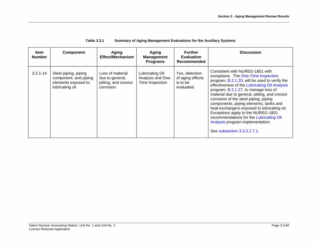
Section 3 - Aging Management Review Results
Salem Nuclear Generating Station, Unit No. 1 and Unit No. 2 Page 3.3-60 License Renewal Application
Table 3.3.1 Summary of Aging Management Evaluations for the Auxiliary Systems
Item Number
Component Aging Effect/Mechanism
Aging Management
Programs
Further Evaluation
Recommended
Discussion
3.3.1-14 Steel piping, piping component, and piping elements exposed to lubricating oil
Loss of material due to general, pitting, and crevice corrosion
Lubricating Oil Analysis and One-Time Inspection
Yes, detection of aging effects is to be evaluated
Consistent with NUREG-1801 with exceptions. The One-Time Inspection program, B.2.1.20, will be used to verify the effectiveness of the Lubricating Oil Analysis program, B.2.1.27, to manage loss of material due to general, pitting, and crevice corrosion of the steel piping, piping components, piping elements, tanks and heat exchangers exposed to lubricating oil. Exceptions apply to the NUREG-1801 recommendations for the Lubricating Oil Analysis program implementation.
See subsection 3.3.2.2.7.1.

Section 3 - Aging Management Review Results
Salem Nuclear Generating Station, Unit No. 1 and Unit No. 2 Page 3.3-61 License Renewal Application
Table 3.3.1 Summary of Aging Management Evaluations for the Auxiliary Systems
Item Number
Component Aging Effect/Mechanism
Aging Management
Programs
Further Evaluation
Recommended
Discussion
3.3.1-15 Steel reactor coolant pump oil collection system piping, tubing, and valve bodies exposed to lubricating oil
Loss of material due to general, pitting, and crevice corrosion
Lubricating Oil Analysis and One-Time Inspection
Yes, detection of aging effects is to be evaluated
Consistent with NUREG-1801 with exceptions. The One-Time Inspection program, B.2.1.20, will be used to verify the effectiveness of the Lubricating Oil Analysis program, B.2.1.27, to manage loss of material due to general, pitting, and crevice corrosion of the reactor coolant pump oil collection system steel piping exposed to lubricating oil for the Fire Protection System.
Exceptions apply to the NUREG-1801 recommendations for the Lubricating Oil Analysis program implementation.
See subsection 3.3.2.2.7.1.
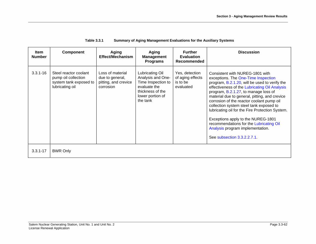
Section 3 - Aging Management Review Results
Salem Nuclear Generating Station, Unit No. 1 and Unit No. 2 Page 3.3-62 License Renewal Application
Table 3.3.1 Summary of Aging Management Evaluations for the Auxiliary Systems
Item Number
Component Aging Effect/Mechanism
Aging Management
Programs
Further Evaluation
Recommended
Discussion
3.3.1-16 Steel reactor coolant pump oil collection system tank exposed to lubricating oil
Loss of material due to general, pitting, and crevice corrosion
Lubricating Oil Analysis and One-Time Inspection to evaluate the thickness of the lower portion of the tank
Yes, detection of aging effects is to be evaluated
Consistent with NUREG-1801 with exceptions. The One-Time Inspection program, B.2.1.20, will be used to verify the effectiveness of the Lubricating Oil Analysis program, B.2.1.27, to manage loss of material due to general, pitting, and crevice corrosion of the reactor coolant pump oil collection system steel tank exposed to lubricating oil for the Fire Protection System.
Exceptions apply to the NUREG-1801 recommendations for the Lubricating Oil Analysis program implementation.
See subsection 3.3.2.2.7.1.
3.3.1-17 BWR Only

Section 3 - Aging Management Review Results
Salem Nuclear Generating Station, Unit No. 1 and Unit No. 2 Page 3.3-63 License Renewal Application
Table 3.3.1 Summary of Aging Management Evaluations for the Auxiliary Systems
Item Number
Component Aging Effect/Mechanism
Aging Management
Programs
Further Evaluation
Recommended
Discussion
3.3.1-18 Stainless steel and steel diesel engine exhaust piping, piping components, and piping elements exposed to diesel exhaust
Loss of material/ general (steel only), pitting and crevice corrosion
A plant specific aging management program is to be evaluated.
Yes, plant specific
Salem will implement the Inspection of Internal Surfaces in Miscellaneous Piping and Ducting Components program, B.2.1.26, to manage loss of material due to general, pitting and crevice corrosion of the steel silencer/muffler, piping, piping components, and piping elements exposed to diesel exhaust for the Emergency Diesel Generator & Auxiliaries System.
Salem will implement a Periodic Inspection program, B.2.2.2, to manage loss of material due to pitting and crevice corrosion of the stainless steel expansion joints exposed to diesel exhaust for the Emergency Diesel Generator & Auxiliaries System.
See subsection 3.3.2.2.7.3.

Section 3 - Aging Management Review Results
Salem Nuclear Generating Station, Unit No. 1 and Unit No. 2 Page 3.3-64 License Renewal Application
Table 3.3.1 Summary of Aging Management Evaluations for the Auxiliary Systems
Item Number
Component Aging Effect/Mechanism
Aging Management
Programs
Further Evaluation
Recommended
Discussion
3.3.1-19 Steel (with or without coating or wrapping) piping, piping components, and piping elements exposed to soil
Loss of material due to general, pitting, crevice, and microbiologically influenced corrosion
Buried Piping and Tanks Surveillance or Buried Piping and Tanks Inspection
No Yes, detection of aging effects and operating experience are to be further evaluated
Consistent with NUREG-1801. The Buried Piping Inspection program, B.2.1.22, will be used to manage loss of material due to general, pitting, crevice, and microbiologically-influenced corrosion of the steel structural components exposed to soil in the Compressed Air, Fire Protection, Non-radioactive Drain, and Service Water Systems.
See Subsection 3.3.2.2.8.
Components in the Fire Protection system have been aligned to this item number based on material, environment and aging effect. The Aboveground Steel Tank program, B.2.1.17, will be substituted to manage loss of material due to general, pitting, crevice, and microbiologically-influenced corrosion of the steel tanks exposed to soil for the Fire Protection System.
Components in the Containment Structure, and Fuel Handling Building have been aligned to this item number based on material, environment and aging effect. The Buried Non-Steel Piping Inspection, B.2.2.4, will be substituted to manage loss of material due to general, pitting, crevice, and microbiologically-influenced corrosion of the
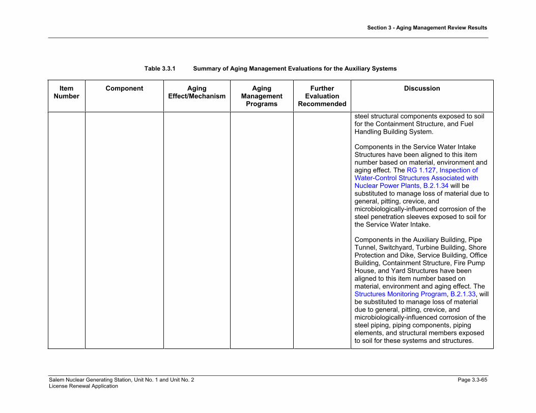
Section 3 - Aging Management Review Results
Salem Nuclear Generating Station, Unit No. 1 and Unit No. 2 Page 3.3-65 License Renewal Application
Table 3.3.1 Summary of Aging Management Evaluations for the Auxiliary Systems
ItemNumber
Component Aging Effect/Mechanism
AgingManagement
Programs
Further Evaluation
Recommended
Discussion
steel structural components exposed to soil for the Containment Structure, and Fuel Handling Building System.
Components in the Service Water Intake Structures have been aligned to this item number based on material, environment and aging effect. The RG 1.127, Inspection of Water-Control Structures Associated with Nuclear Power Plants, B.2.1.34 will be substituted to manage loss of material due to general, pitting, crevice, and microbiologically-influenced corrosion of the steel penetration sleeves exposed to soil for the Service Water Intake.
Components in the Auxiliary Building, Pipe Tunnel, Switchyard, Turbine Building, Shore Protection and Dike, Service Building, Office Building, Containment Structure, Fire Pump House, and Yard Structures have been aligned to this item number based on material, environment and aging effect. The Structures Monitoring Program, B.2.1.33, will be substituted to manage loss of material due to general, pitting, crevice, and microbiologically-influenced corrosion of the steel piping, piping components, piping elements, and structural members exposed to soil for these systems and structures.

Section 3 - Aging Management Review Results
Salem Nuclear Generating Station, Unit No. 1 and Unit No. 2 Page 3.3-66 License Renewal Application
Table 3.3.1 Summary of Aging Management Evaluations for the Auxiliary Systems
Item Number
Component Aging Effect/Mechanism
Aging Management
Programs
Further Evaluation
Recommended
Discussion
3.3.1-20 Steel piping, piping components, piping elements, and tanks exposed to fuel oil
Loss of material due to general, pitting, crevice, and microbiologically influenced corrosion, and fouling
Fuel Oil Chemistry and One-Time Inspection
Yes, detection of aging effects is to be evaluated)
Consistent with NUREG-1801 with exceptions. The One-Time Inspection program, B.2.1.20, will be used to verify the effectiveness of the Fuel Oil Chemistry program, B.2.1.18, to manage loss of material due to general, pitting, crevice, and microbiologically-influenced corrosion, and fouling of the steel piping, piping components, piping elements, and tanks exposed to fuel oil for the Fuel Oil System.
Exceptions apply to the NUREG-1801 recommendations for Fuel Oil program implementation.
See subsection 3.3.2.2.9.1.
3.3.1-21 Steel heat exchanger components exposed to lubricating oil
Loss of material due to general, pitting, crevice, and microbiologically influenced corrosion, and fouling
Lubricating Oil Analysis and One-Time Inspection
Yes, detection of aging effects is to be evaluated
Not Applicable.
See subsection 3.3.2.2.9.2.

Section 3 - Aging Management Review Results
Salem Nuclear Generating Station, Unit No. 1 and Unit No. 2 Page 3.3-67 License Renewal Application
Table 3.3.1 Summary of Aging Management Evaluations for the Auxiliary Systems
Item Number
Component Aging Effect/Mechanism
Aging Management
Programs
Further Evaluation
Recommended
Discussion
3.3.1-22 Steel with elastomer lining or stainless steel cladding piping, piping components, and piping elements exposed to treated water and treated borated water
Loss of material due to pitting and crevice corrosion (only for steel after lining/cladding degradation)
Water Chemistry and One-Time Inspection
Yes, detection of aging effects is to be evaluated
Not Applicable.
See subsection 3.3.2.2.10.1.
3.3.1-23 BWR Only
3.3.1-24 Stainless steel and aluminum piping, piping components, and piping elements exposed to treated water
Loss of material due to pitting and crevice corrosion
Water Chemistry and One-Time Inspection
Yes, detection of aging effects is to be evaluated
Consistent with NUREG-1801. The Water Chemistry program, B.2.1.2, and the One-Time Chemistry program, B.2.1.20, will be used to manage loss of material due to pitting and crevice corrosion of the stainless steel piping, piping components, piping elements and tanks exposed to treated water in Chemical & Volume Control, Containment Spray, and Reactor Coolant Systems.
See subsection 3.3.2.2.10.2.

Section 3 - Aging Management Review Results
Salem Nuclear Generating Station, Unit No. 1 and Unit No. 2 Page 3.3-68 License Renewal Application
Table 3.3.1 Summary of Aging Management Evaluations for the Auxiliary Systems
Item Number
Component Aging Effect/Mechanism
Aging Management
Programs
Further Evaluation
Recommended
Discussion
3.3.1-25 Copper alloy HVAC piping, piping components, piping elements exposed to condensation (external)
Loss of material due to pitting and crevice corrosion
A plant-specific aging management program is to be evaluated.
Yes, plant specific
The Periodic Inspection program, B.2.2.2, will be used to manage loss of material due to pitting and crevice corrosion of the copper alloy HVAC piping, piping components, piping elements and HVAC heat exchanger components exposed to air/gas-wetted for the Auxiliary Building Ventilation, Chilled Water, Control Area Ventilation, and Heating Water and Heating Steam Systems.
See subsection 3.3.2.2.10.3
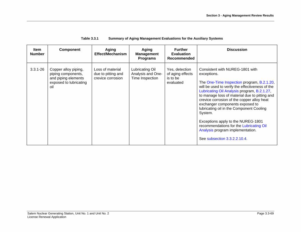
Section 3 - Aging Management Review Results
Salem Nuclear Generating Station, Unit No. 1 and Unit No. 2 Page 3.3-69 License Renewal Application
Table 3.3.1 Summary of Aging Management Evaluations for the Auxiliary Systems
Item Number
Component Aging Effect/Mechanism
Aging Management
Programs
Further Evaluation
Recommended
Discussion
3.3.1-26 Copper alloy piping, piping components, and piping elements exposed to lubricating oil
Loss of material due to pitting and crevice corrosion
Lubricating Oil Analysis and One-Time Inspection
Yes, detection of aging effects is to be evaluated
Consistent with NUREG-1801 with exceptions.
The One-Time Inspection program, B.2.1.20, will be used to verify the effectiveness of the Lubricating Oil Analysis program, B.2.1.27, to manage loss of material due to pitting and crevice corrosion of the copper alloy heat exchanger components exposed to lubricating oil in the Component Cooling System.
Exceptions apply to the NUREG-1801 recommendations for the Lubricating Oil Analysis program implementation.
See subsection 3.3.2.2.10.4.

Section 3 - Aging Management Review Results
Salem Nuclear Generating Station, Unit No. 1 and Unit No. 2 Page 3.3-70 License Renewal Application
Table 3.3.1 Summary of Aging Management Evaluations for the Auxiliary Systems
ItemNumber
Component Aging Effect/Mechanism
AgingManagement
Programs
Further Evaluation
Recommended
Discussion
3.3.1-27 Stainless steel HVAC ducting and aluminum HVAC piping, piping components and piping elements exposed to condensation
Loss of material due to pitting and crevice corrosion
A plant-specific agingmanagement program is to be evaluated.
Yes, plant specific
The Periodic Inspection, B.2.2.2, will be used to manage loss of material due to pitting and crevice corrosion of the aluminum and stainless steel HVAC piping, piping components, piping elements exposed to air/gas-wetted and air with steam or water leakage for the Auxiliary Building Ventilation, Chemical & Volume Control, Component Cooling, Compressed Air, Containment Spray, Containment Ventilation, Control Area Ventilation, Emergency Diesel Generators & Auxiliaries, Fuel Handling Ventilation, Radioactive Drain, Reactor Coolant, Residual Heat Removal, Safety Injection, Service Water, Service Water Ventilation, and Switchgear and Penetration Ventilation Systems.
The Fire Protection program, B.2.1.15, will be used to manage loss of material due to pitting and crevice corrosion of the aluminum piping elements exposed to air/gas-wetted for the Fire Protection System.
See subsection 3.3.2.2.10.5.

Section 3 - Aging Management Review Results
Salem Nuclear Generating Station, Unit No. 1 and Unit No. 2 Page 3.3-71 License Renewal Application
Table 3.3.1 Summary of Aging Management Evaluations for the Auxiliary Systems
Item Number
Component Aging Effect/Mechanism
Aging Management
Programs
Further Evaluation
Recommended
Discussion
3.3.1-28 Copper alloy fire protection piping, piping components, and piping elements exposed to condensation (internal)
Loss of material due to pitting and crevice corrosion
A plant-specific aging management program is to be evaluated.
Yes, plant specific
The Periodic Inspection program, B.2.2.2, will be used to manage loss of material due to pitting and crevice corrosion of the copper alloy fire protection piping, piping components, piping elements and heat exchanger components exposed to air/gas – wetted for the Chilled Water and Emergency Diesel Generators & Auxiliaries Systems.
The Compressed Air Monitoring program, B.2.1.14, will be used to manage loss of material due to pitting and crevice corrosion of the copper alloy piping components exposed to air/gas – wetted for the Compressed Air System.
The Fire Protection program, B.2.1.15, will be used to manage loss of material due to pitting and crevice corrosion of the copper alloy piping and piping components exposed to air/gas – wetted for the Fire Protection System.
The Fire Water System program, B.2.1.16, will be used to manage loss of material due to pitting and crevice corrosion of the copper alloy fire protection piping and piping components, valves, and piping elements exposed to air/gas – wetted for the Fire Protection System.

Section 3 - Aging Management Review Results
Salem Nuclear Generating Station, Unit No. 1 and Unit No. 2 Page 3.3-72 License Renewal Application
Table 3.3.1 Summary of Aging Management Evaluations for the Auxiliary Systems
Item Number
Component Aging Effect/Mechanism
Aging Management
Programs
Further Evaluation
Recommended
Discussion
See subsection 3.3.2.2.10.6.
3.3.1-29 Stainless steel piping, piping components, and piping elements exposed to soil
Loss of material due to pitting and crevice corrosion
A plant-specific aging management program is to be evaluated.
Yes, plant specific
Not Applicable.
See subsection 3.3.2.2.10.7.
3.3.1-30 BWR Only
3.3.1-31 BWR Only
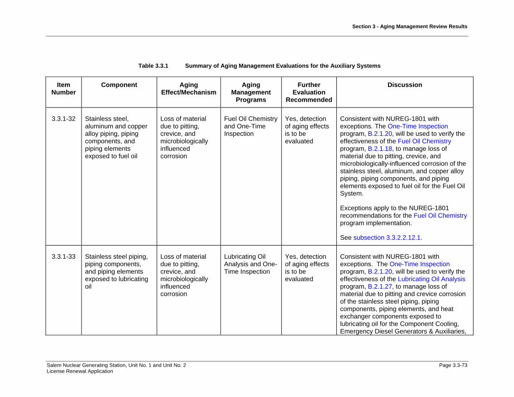
Section 3 - Aging Management Review Results
Salem Nuclear Generating Station, Unit No. 1 and Unit No. 2 Page 3.3-73 License Renewal Application
Table 3.3.1 Summary of Aging Management Evaluations for the Auxiliary Systems
Item Number
Component Aging Effect/Mechanism
Aging Management
Programs
Further Evaluation
Recommended
Discussion
3.3.1-32 Stainless steel, aluminum and copper alloy piping, piping components, and piping elements exposed to fuel oil
Loss of material due to pitting, crevice, and microbiologically influenced corrosion
Fuel Oil Chemistry and One-Time Inspection
Yes, detection of aging effects is to be evaluated
Consistent with NUREG-1801 with exceptions. The One-Time Inspection program, B.2.1.20, will be used to verify the effectiveness of the Fuel Oil Chemistry program, B.2.1.18, to manage loss of material due to pitting, crevice, and microbiologically-influenced corrosion of the stainless steel, aluminum, and copper alloy piping, piping components, and piping elements exposed to fuel oil for the Fuel Oil System.
Exceptions apply to the NUREG-1801 recommendations for the Fuel Oil Chemistry program implementation.
See subsection 3.3.2.2.12.1.
3.3.1-33 Stainless steel piping, piping components, and piping elements exposed to lubricating oil
Loss of material due to pitting, crevice, and microbiologically influenced corrosion
Lubricating Oil Analysis and One-Time Inspection
Yes, detection of aging effects is to be evaluated
Consistent with NUREG-1801 with exceptions. The One-Time Inspection program, B.2.1.20, will be used to verify the effectiveness of the Lubricating Oil Analysis program, B.2.1.27, to manage loss of material due to pitting and crevice corrosion of the stainless steel piping, piping components, piping elements, and heat exchanger components exposed to lubricating oil for the Component Cooling, Emergency Diesel Generators & Auxiliaries,

Section 3 - Aging Management Review Results
Salem Nuclear Generating Station, Unit No. 1 and Unit No. 2 Page 3.3-74 License Renewal Application
Table 3.3.1 Summary of Aging Management Evaluations for the Auxiliary Systems
Item Number
Component Aging Effect/Mechanism
Aging Management
Programs
Further Evaluation
Recommended
Discussion
Reactor Coolant, and Service Water Systems.
Exceptions apply to the NUREG-1801 recommendations for Lubricating Oil Analysis program implementation.
See subsection 3.3.2.2.12.2.
3.3.1-34 Elastomer seals and components exposed to air – indoor uncontrolled (internal or external)
Loss of material due to Wear
A plant specific aging management program is to be evaluated.
Yes, plant specific
Not Applicable.
See subsection 3.3.2.2.13.
3.3.1-35 Steel with stainless steel cladding pump casing exposed to treated borated water
Loss of material due to cladding breach
A plant-specific aging management program is to be evaluated. Reference NRC Information Notice 94-63, “Boric Acid Corrosion of Charging Pump Casings Caused by Cladding Cracks."
Yes, verify plant-specific program addresses cladding breach
Consistent with NUREG-1801. The One-Time Inspection program, B.2.1.20, will be used to manage loss of material due to cladding breach of the steel with stainless steel cladding pump casing exposed to treated borated water for the Chemical & Volume Control System.
See subsection 3.3.2.2.14.

Section 3 - Aging Management Review Results
Salem Nuclear Generating Station, Unit No. 1 and Unit No. 2 Page 3.3-75 License Renewal Application
Table 3.3.1 Summary of Aging Management Evaluations for the Auxiliary Systems
Item Number
Component Aging Effect/Mechanism
Aging Management
Programs
Further Evaluation
Recommended
Discussion
3.3.1-36 BWR Only
3.3.1-37 BWR Only
3.3.1-38 BWR Only
3.3.1-39 BWR Only
3.3.1-40 Steel tanks in diesel fuel oil system exposed to air - outdoor (external)
Loss of material due to general, pitting, and crevice corrosion
Aboveground Steel Tanks
No Consistent with NUREG-1801. The Aboveground Steel Tanks program, B.2.1.17, will be used to manage loss of material due to general, pitting, and crevice corrosion of the steel tanks exposed to outdoor air in the Fire Protection System.
3.3.1-41 High-strength steel closure bolting exposed to air with steam or water leakage
Cracking due to cyclic loading, stress corrosion cracking
Bolting Integrity No Not Applicable. This component, material, environment, and aging effect/mechanism does not apply to Auxiliary Systems.
There is no high strength closure bolting in the Auxiliary Systems.
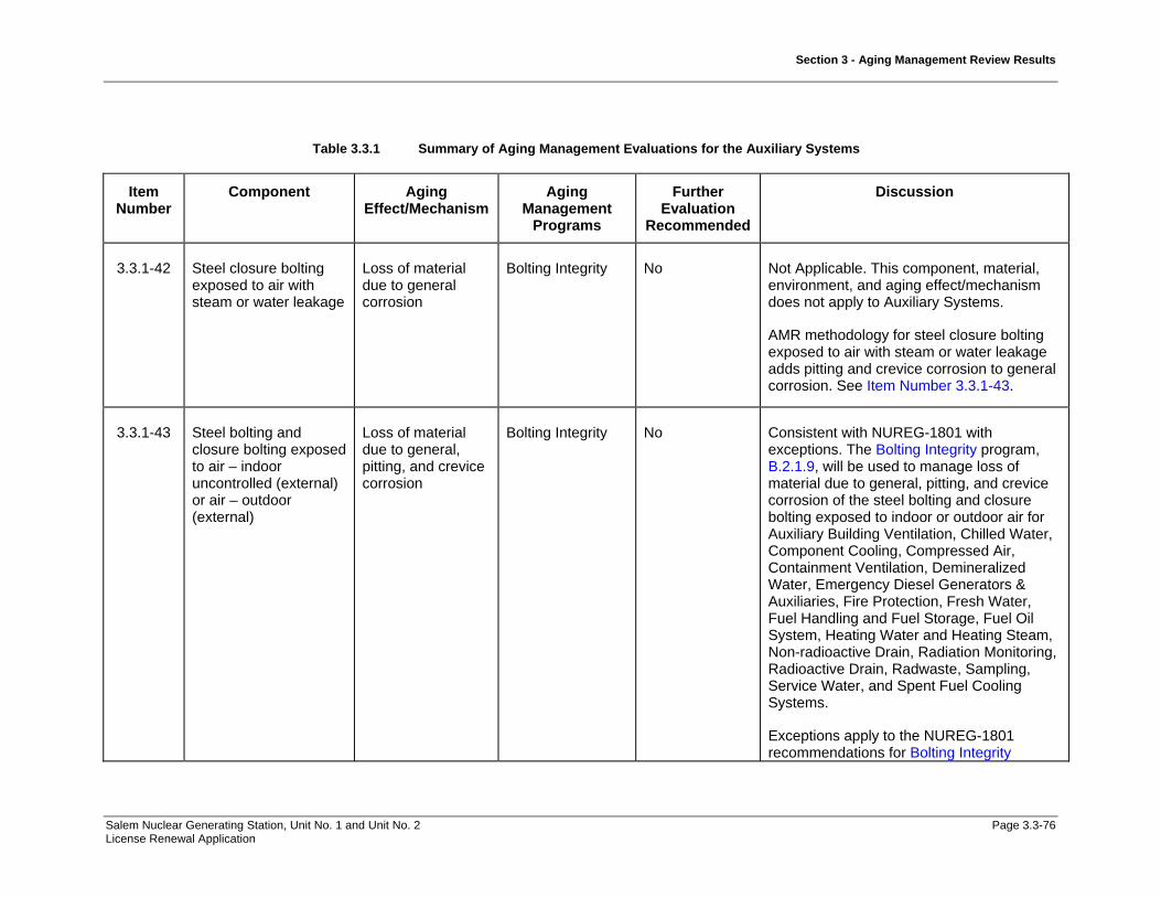
Section 3 - Aging Management Review Results
Salem Nuclear Generating Station, Unit No. 1 and Unit No. 2 Page 3.3-76 License Renewal Application
Table 3.3.1 Summary of Aging Management Evaluations for the Auxiliary Systems
Item Number
Component Aging Effect/Mechanism
Aging Management
Programs
Further Evaluation
Recommended
Discussion
3.3.1-42 Steel closure bolting exposed to air with steam or water leakage
Loss of material due to general corrosion
Bolting Integrity No Not Applicable. This component, material, environment, and aging effect/mechanism does not apply to Auxiliary Systems.
AMR methodology for steel closure bolting exposed to air with steam or water leakage adds pitting and crevice corrosion to general corrosion. See Item Number 3.3.1-43.
3.3.1-43 Steel bolting and closure bolting exposed to air – indoor uncontrolled (external) or air – outdoor (external)
Loss of material due to general, pitting, and crevice corrosion
Bolting Integrity No Consistent with NUREG-1801 with exceptions. The Bolting Integrity program, B.2.1.9, will be used to manage loss of material due to general, pitting, and crevice corrosion of the steel bolting and closure bolting exposed to indoor or outdoor air for Auxiliary Building Ventilation, Chilled Water, Component Cooling, Compressed Air, Containment Ventilation, Demineralized Water, Emergency Diesel Generators & Auxiliaries, Fire Protection, Fresh Water, Fuel Handling and Fuel Storage, Fuel Oil System, Heating Water and Heating Steam, Non-radioactive Drain, Radiation Monitoring, Radioactive Drain, Radwaste, Sampling, Service Water, and Spent Fuel Cooling Systems.
Exceptions apply to the NUREG-1801 recommendations for Bolting Integrity

Section 3 - Aging Management Review Results
Salem Nuclear Generating Station, Unit No. 1 and Unit No. 2 Page 3.3-77 License Renewal Application
Table 3.3.1 Summary of Aging Management Evaluations for the Auxiliary Systems
Item Number
Component Aging Effect/Mechanism
Aging Management
Programs
Further Evaluation
Recommended
Discussion
program implementation.
Components in the Switchgear and Penetration Area Ventilation system have been aligned to this item number based on material, environment and aging effect. The External Surfaces Monitoring program, B.2.1.24, will be substituted to manage the loss of material due to general, pitting, and crevice corrosion of steel closure bolting exposed to outdoor air.
Components in the Cranes and Hoists, and Fuel Handling and Fuel Storage Systems have been aligned to this item number based on material, environment and aging effect. The Inspection of Overhead Heavy Load and Light Load (Related to Refueling) Handling Systems program, B.2.1.13, has been substituted to manage the loss of material due to general, pitting, and crevice corrosion of steel bolting exposed to indoor and outdoor air.
3.3.1-44 Steel compressed air system closure bolting exposed to condensation
Loss of material due to general, pitting, and crevice corrosion
Bolting Integrity No Not Applicable. There is no steel compressed air system closure bolting exposed to condensation in the Auxiliary Systems.
3.3.1-45 Steel closure bolting Loss of preload Bolting Integrity No Consistent with NUREG-1801 with

Section 3 - Aging Management Review Results
Salem Nuclear Generating Station, Unit No. 1 and Unit No. 2 Page 3.3-78 License Renewal Application
Table 3.3.1 Summary of Aging Management Evaluations for the Auxiliary Systems
Item Number
Component Aging Effect/Mechanism
Aging Management
Programs
Further Evaluation
Recommended
Discussion
exposed to air – indoor uncontrolled (external)
due to thermal effects, gasket creep, and self-loosening
exceptions. The Bolting Integrity program, B.2.1.9, will be used to manage loss of preload due to thermal effects, gasket creep, and self-loosening of the steel closure bolting exposed to indoor air for the Chilled Water, Component Cooling, Compressed Air, Containment Ventilation, Demineralized Water, Emergency Diesel Generators & Auxiliaries , Fire Protection, Fresh Water, Fuel Handling and Fuel Storage, Fuel Oil, Heating Water and Heating Steam, Non-radioactive Drain, Radiation Monitoring, Radioactive Drain, Radwaste, Sampling, Service Water, and Spent Fuel Cooling Systems.
Exceptions apply to the NUREG-1801 recommendations for Bolting Integrity program implementation.
Components in the Cranes and Hoists, and Fuel Handling and Fuel Storage Systems have been aligned to this item number based on material, environment and aging effect. The Inspection of Overhead Heavy Load and Light Load (Related to Refueling) Handling Systems program, B.2.1.13, has been substituted to manage loss of preload due to self-loosening of steel bolting exposed to indoor air for these systems.
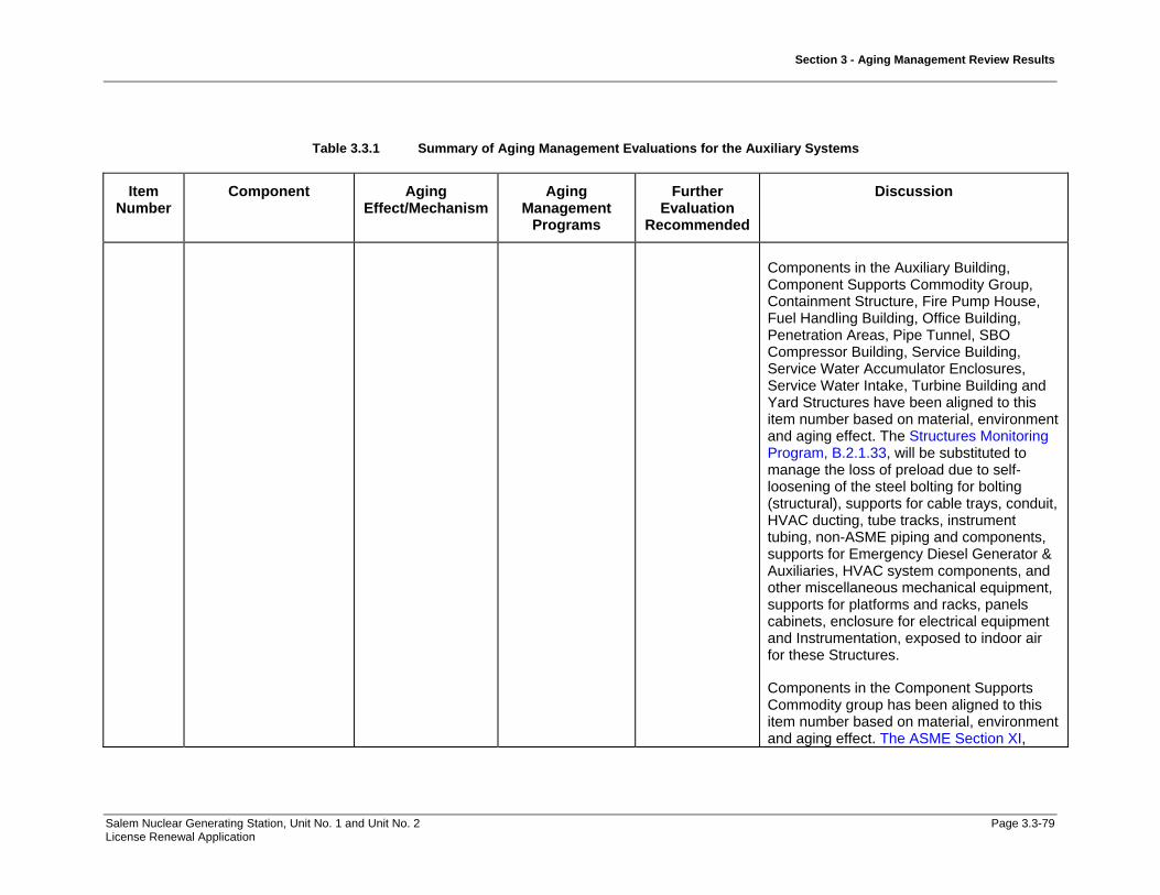
Section 3 - Aging Management Review Results
Salem Nuclear Generating Station, Unit No. 1 and Unit No. 2 Page 3.3-79 License Renewal Application
Table 3.3.1 Summary of Aging Management Evaluations for the Auxiliary Systems
Item Number
Component Aging Effect/Mechanism
Aging Management
Programs
Further Evaluation
Recommended
Discussion
Components in the Auxiliary Building, Component Supports Commodity Group, Containment Structure, Fire Pump House, Fuel Handling Building, Office Building, Penetration Areas, Pipe Tunnel, SBO Compressor Building, Service Building, Service Water Accumulator Enclosures, Service Water Intake, Turbine Building and Yard Structures have been aligned to this item number based on material, environment and aging effect. The Structures Monitoring Program, B.2.1.33, will be substituted to manage the loss of preload due to self-loosening of the steel bolting for bolting (structural), supports for cable trays, conduit, HVAC ducting, tube tracks, instrument tubing, non-ASME piping and components, supports for Emergency Diesel Generator & Auxiliaries, HVAC system components, and other miscellaneous mechanical equipment, supports for platforms and racks, panels cabinets, enclosure for electrical equipment and Instrumentation, exposed to indoor air for these Structures.
Components in the Component Supports Commodity group has been aligned to this item number based on material, environment and aging effect. The ASME Section XI,

Section 3 - Aging Management Review Results
Salem Nuclear Generating Station, Unit No. 1 and Unit No. 2 Page 3.3-80 License Renewal Application
Table 3.3.1 Summary of Aging Management Evaluations for the Auxiliary Systems
Item Number
Component Aging Effect/Mechanism
Aging Management
Programs
Further Evaluation
Recommended
Discussion
Subsection IWF program, B.2.1.30, will be substituted to manage the loss of preload of component supports commodity group due to self-loosening of the steel bolting exposed to indoor air for the Component Supports Commodity group.
3.3.1-46 Stainless steel and stainless clad steel piping, piping components, piping elements, and heat exchanger components exposed to closed cycle cooling water >60°C (>140°F)
Cracking due to stress corrosion cracking
Closed-Cycle Cooling Water System
No Consistent with NUREG-1801 with exceptions. The Closed-Cycle Cooling Water System program, B.2.1.12, will be used to manage cracking due to stress corrosion cracking of the stainless steel piping, piping components, piping elements, and heat exchanger components exposed to closed cycle cooling water >140°F for Demineralized Water, Emergency Diesel Generators & Auxiliaries, Fire Protection, and the Heating Water and Heating Steam Systems.
Exceptions apply to the NUREG-1801 recommendations for Closed-Cycle Cooling Water System program implementation.

Section 3 - Aging Management Review Results
Salem Nuclear Generating Station, Unit No. 1 and Unit No. 2 Page 3.3-81 License Renewal Application
Table 3.3.1 Summary of Aging Management Evaluations for the Auxiliary Systems
Item Number
Component Aging Effect/Mechanism
Aging Management
Programs
Further Evaluation
Recommended
Discussion
3.3.1-47 Steel piping, piping components, piping elements, tanks, and heat exchanger components exposed to closed cycle cooling water
Loss of material due to general, pitting, and crevice corrosion
Closed-Cycle Cooling Water System
No Consistent with NUREG-1801 with exceptions. The Closed-Cycle Cooling Water System program, B.2.1.12, will be used to manage loss of material due to general, pitting, and crevice corrosion of the steel piping, piping components, piping elements, tanks, and heat exchanger components exposed to closed cycle cooling water for the Chilled Water, Component Cooling, Emergency Diesel Generators & Auxiliaries, and Heating Water and Heating Steam Systems.
Exceptions apply to the NUREG-1801 recommendations for Closed-Cycle Cooling Water System program implementation.

Section 3 - Aging Management Review Results
Salem Nuclear Generating Station, Unit No. 1 and Unit No. 2 Page 3.3-82 License Renewal Application
Table 3.3.1 Summary of Aging Management Evaluations for the Auxiliary Systems
Item Number
Component Aging Effect/Mechanism
Aging Management
Programs
Further Evaluation
Recommended
Discussion
3.3.1-48 Steel piping, piping components, piping elements, tanks, and heat exchanger components exposed to closed cycle cooling water
Loss of material due to general, pitting, crevice, and galvanic corrosion
Closed-Cycle Cooling Water System
No Consistent with NUREG-1801 with exceptions. The Closed-Cycle Cooling Water System program, B.2.1.12, will be used to manage loss of material due to loss of material due to general, pitting, crevice, and galvanic corrosion of the steel heat exchanger components exposed to closed cycle cooling water for Chilled Water, Component Cooling, and Service Water Systems.
Exceptions apply to NUREG-1801 recommendations for closed cycle cooling water system program implementation.
3.3.1-49 Stainless steel; steel with stainless steel cladding heat exchanger components exposed to closed cycle cooling water
Loss of material due to microbiologically influenced corrosion
Closed-Cycle Cooling Water System
No Not Applicable. AMR methodology for stainless steel heat exchanger components exposed to closed cycle cooling water predicts loss of material due to pitting and crevice corrosion. Loss of material due to microbiologically-influenced corrosion is not predicted for these stainless steel heat exchanger components exposed to closed cycle cooling water, based on plant-specific operating experience. See Item Number 3.3.1-50.

Section 3 - Aging Management Review Results
Salem Nuclear Generating Station, Unit No. 1 and Unit No. 2 Page 3.3-83 License Renewal Application
Table 3.3.1 Summary of Aging Management Evaluations for the Auxiliary Systems
Item Number
Component Aging Effect/Mechanism
Aging Management
Programs
Further Evaluation
Recommended
Discussion
3.3.1-50 Stainless steel piping, piping components, and piping elements exposed to closed cycle cooling water
Loss of material due to pitting and crevice corrosion
Closed-Cycle Cooling Water System
No Consistent with NUREG-1801 with exceptions. The Closed-Cycle Cooling Water System program, B.2.1.12, will be used to manage loss of material due to pitting and crevice corrosion of the stainless steel piping, piping components, piping elements, and heat exchanger components exposed to closed cycle cooling water for Chemical & Volume Control, Chilled Water, Component Cooling, Demineralized Water, Emergency Diesel Generators & Auxiliaries System, Fire Protection, and Heating Water and Heating Steam Systems.
Exceptions apply to the NUREG-1801 recommendations for Closed-Cycle Cooling Water System program implementation.

Section 3 - Aging Management Review Results
Salem Nuclear Generating Station, Unit No. 1 and Unit No. 2 Page 3.3-84 License Renewal Application
Table 3.3.1 Summary of Aging Management Evaluations for the Auxiliary Systems
Item Number
Component Aging Effect/Mechanism
Aging Management
Programs
Further Evaluation
Recommended
Discussion
3.3.1-51 Copper alloy piping, piping components, piping elements, and heat exchanger components exposed to closed cycle cooling water
Loss of material due to pitting, crevice, and galvanic corrosion
Closed-Cycle Cooling Water System
No Consistent with NUREG-1801 with exceptions. The Closed-Cycle Cooling Water System program, B.2.1.12, will be used to manage loss of material due to pitting, crevice, and galvanic corrosion of the copper alloy piping, piping components, piping elements, and heat exchanger components exposed to closed cycle cooling water in the Chilled Water, Component Cooling, Emergency Diesel Generators & Auxiliaries and Heating Water and Heating Steam Systems.
Exceptions apply to the NUREG-1801 recommendations for Closed-Cycle Cooling Water System program implementation.
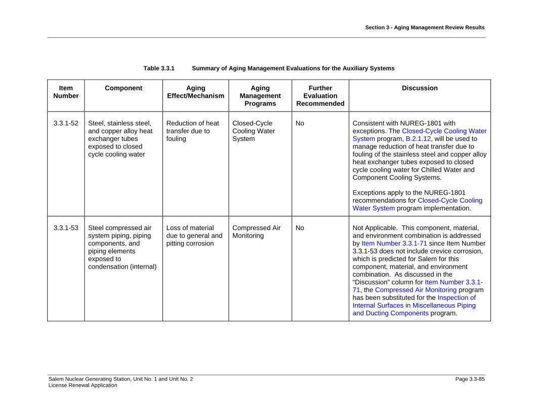
Section 3 - Aging Management Review Results
Salem Nuclear Generating Station, Unit No. 1 and Unit No. 2 Page 3.3-85 License Renewal Application
Table 3.3.1 Summary of Aging Management Evaluations for the Auxiliary Systems
Item Number
Component Aging Effect/Mechanism
Aging Management
Programs
Further Evaluation
Recommended
Discussion
3.3.1-52 Steel, stainless steel, and copper alloy heat exchanger tubes exposed to closed cycle cooling water
Reduction of heat transfer due to fouling
Closed-Cycle Cooling Water System
No Consistent with NUREG-1801 with exceptions. The Closed-Cycle Cooling Water System program, B.2.1.12, will be used to manage reduction of heat transfer due to fouling of the stainless steel and copper alloy heat exchanger tubes exposed to closed cycle cooling water for Chilled Water and Component Cooling Systems.
Exceptions apply to the NUREG-1801 recommendations for Closed-Cycle Cooling Water System program implementation.
3.3.1-53 Steel compressed air system piping, piping components, and piping elements exposed to condensation (internal)
Loss of material due to general and pitting corrosion
Compressed Air Monitoring
No Not Applicable. This component, material, and environment combination is addressed by Item Number 3.3.1-71 since Item Number 3.3.1-53 does not include crevice corrosion, which is predicted for Salem for this component, material, and environment combination. As discussed in the “Discussion” column for Item Number 3.3.1-71, the Compressed Air Monitoring program has been substituted for the Inspection of Internal Surfaces in Miscellaneous Piping and Ducting Components program.

Section 3 - Aging Management Review Results
Salem Nuclear Generating Station, Unit No. 1 and Unit No. 2 Page 3.3-86 License Renewal Application
Table 3.3.1 Summary of Aging Management Evaluations for the Auxiliary Systems
Item Number
Component Aging Effect/Mechanism
Aging Management
Programs
Further Evaluation
Recommended
Discussion
3.3.1-54 Stainless steel compressed air system piping, piping components, and piping elements exposed to internal condensation
Loss of material due to pitting and crevice corrosion
Compressed Air Monitoring
No Consistent with NUREG-1801. The Compressed Air Monitoring program, B.2.1.14, will be used to manage loss of material due to pitting and crevice corrosion of the stainless steel piping, piping components, and piping elements exposed to air/gas - wetted for the Compressed Air System.
Components in the Compressed Air System, Fuel Handling & Fuel Storage System, Radiation Monitoring System, Radioactive Drain System, Radwaste System, and Emergency Diesel Generators & Auxiliaries System have been aligned to this item number based on material, environment and aging effect. The Periodic Inspection program, B.2.2.2, will be substituted to manage loss of material due to pitting and crevice corrosion of the stainless steel piping, piping components, piping elements and heat exchanger components exposed to air/gas - wetted for these systems.
Components in the Fire Protection System have been aligned to this item number based on material, environment and aging effect. The Fire Protection program, B.2.1.15, will be substituted to manage loss of material due to pitting and crevice corrosion of the
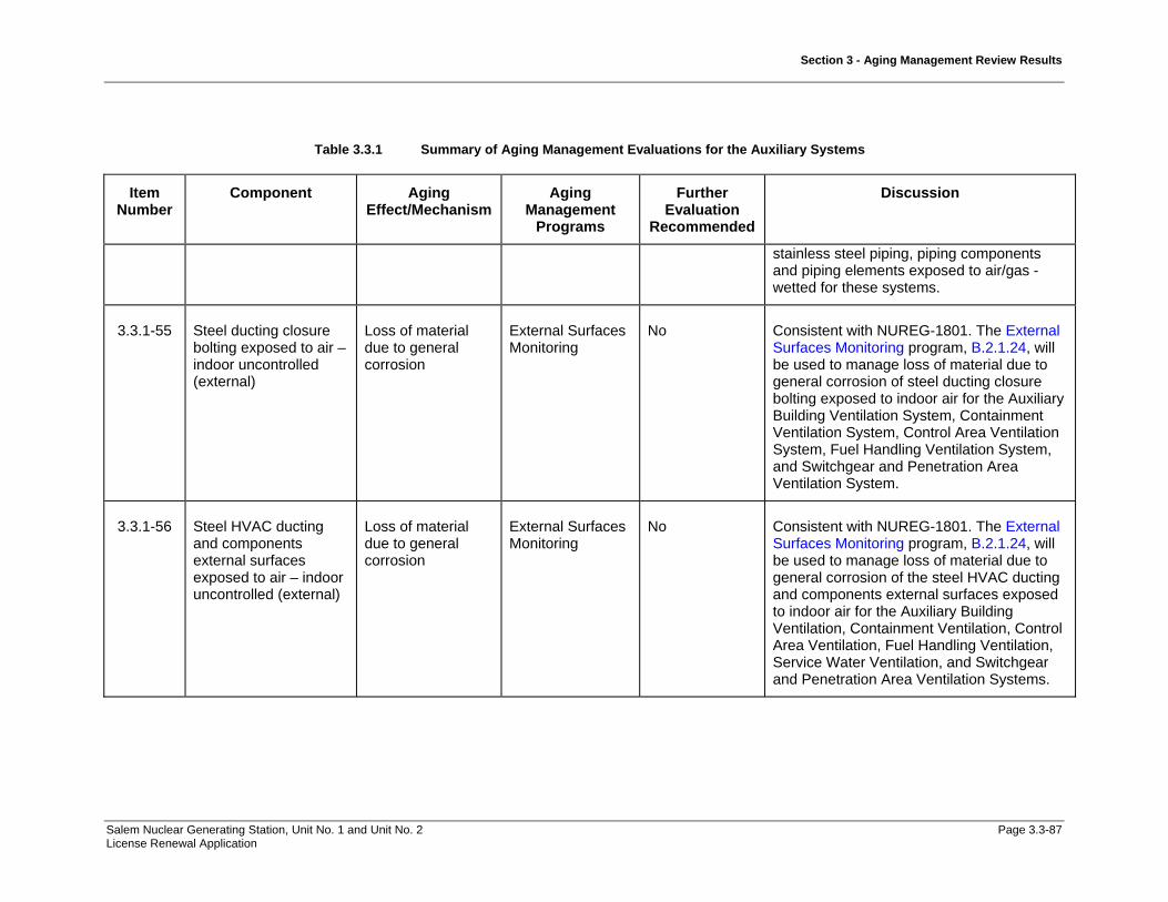
Section 3 - Aging Management Review Results
Salem Nuclear Generating Station, Unit No. 1 and Unit No. 2 Page 3.3-87 License Renewal Application
Table 3.3.1 Summary of Aging Management Evaluations for the Auxiliary Systems
Item Number
Component Aging Effect/Mechanism
Aging Management
Programs
Further Evaluation
Recommended
Discussion
stainless steel piping, piping components and piping elements exposed to air/gas - wetted for these systems.
3.3.1-55 Steel ducting closure bolting exposed to air – indoor uncontrolled (external)
Loss of material due to general corrosion
External Surfaces Monitoring
No Consistent with NUREG-1801. The External Surfaces Monitoring program, B.2.1.24, will be used to manage loss of material due to general corrosion of steel ducting closure bolting exposed to indoor air for the Auxiliary Building Ventilation System, Containment Ventilation System, Control Area Ventilation System, Fuel Handling Ventilation System, and Switchgear and Penetration Area Ventilation System.
3.3.1-56 Steel HVAC ducting and components external surfaces exposed to air – indoor uncontrolled (external)
Loss of material due to general corrosion
External Surfaces Monitoring
No Consistent with NUREG-1801. The External Surfaces Monitoring program, B.2.1.24, will be used to manage loss of material due to general corrosion of the steel HVAC ducting and components external surfaces exposed to indoor air for the Auxiliary Building Ventilation, Containment Ventilation, Control Area Ventilation, Fuel Handling Ventilation, Service Water Ventilation, and Switchgear and Penetration Area Ventilation Systems.

Section 3 - Aging Management Review Results
Salem Nuclear Generating Station, Unit No. 1 and Unit No. 2 Page 3.3-88 License Renewal Application
Table 3.3.1 Summary of Aging Management Evaluations for the Auxiliary Systems
Item Number
Component Aging Effect/Mechanism
Aging Management
Programs
Further Evaluation
Recommended
Discussion
3.3.1-57 Steel piping and components external surfaces exposed to air – indoor uncontrolled (External)
Loss of material due to general corrosion
External Surfaces Monitoring
No Consistent with NUREG-1801. The External Surfaces Monitoring program, B.2.1.24, will be used to manage loss of material due to general corrosion of the steel piping components, and piping elements external surfaces exposed to indoor air for the Compressed Air System, Containment Ventilation System, Fire Protection System, Fuel Oil System, Radioactive Drain System, Radwaste System, and Switchgear and Penetration Area Ventilation Systems.
Components in the Fire Protection System have been aligned to this item number based on material, environment and aging effect. The Fire Protection program, B.2.1.15, and the Fire Water System program, B.2.1.16, will be substituted to manage loss of material due to general corrosion of the steel piping, piping components and piping elements external surfaces exposed to indoor air.
3.3.1-58 Steel external surfaces exposed to air – indoor uncontrolled (external), air - outdoor (external), and condensation (external)
Loss of material due to general corrosion
External Surfaces Monitoring
No Consistent with NUREG-1801. The External Surfaces Monitoring program, B.2.1.24, will be used to manage loss of material due to general corrosion of the steel external surfaces exposed to indoor and outdoor air for the Chemical & Volume Control, Chilled Water, Component Cooling, Compressed
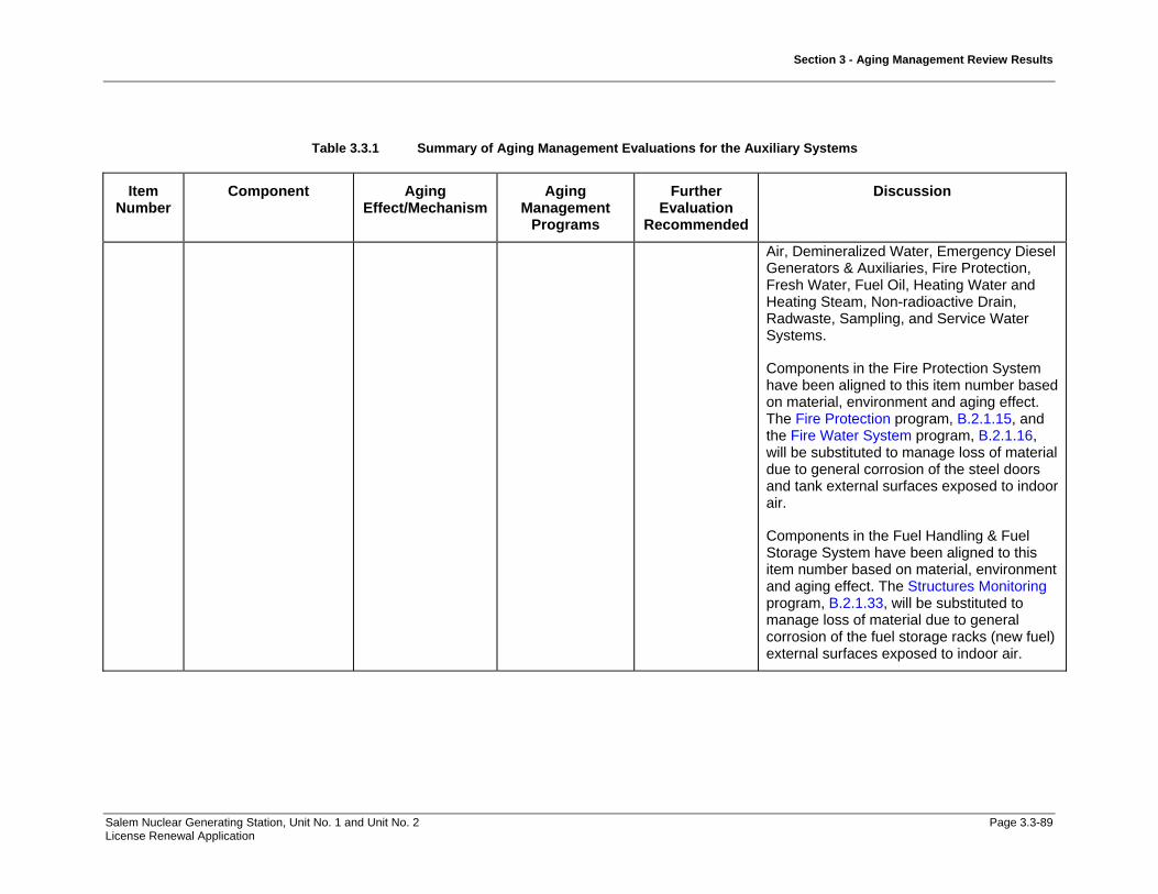
Section 3 - Aging Management Review Results
Salem Nuclear Generating Station, Unit No. 1 and Unit No. 2 Page 3.3-89 License Renewal Application
Table 3.3.1 Summary of Aging Management Evaluations for the Auxiliary Systems
Item Number
Component Aging Effect/Mechanism
Aging Management
Programs
Further Evaluation
Recommended
Discussion
Air, Demineralized Water, Emergency Diesel Generators & Auxiliaries, Fire Protection, Fresh Water, Fuel Oil, Heating Water and Heating Steam, Non-radioactive Drain, Radwaste, Sampling, and Service Water Systems.
Components in the Fire Protection System have been aligned to this item number based on material, environment and aging effect. The Fire Protection program, B.2.1.15, and the Fire Water System program, B.2.1.16, will be substituted to manage loss of material due to general corrosion of the steel doors and tank external surfaces exposed to indoor air.
Components in the Fuel Handling & Fuel Storage System have been aligned to this item number based on material, environment and aging effect. The Structures Monitoring program, B.2.1.33, will be substituted to manage loss of material due to general corrosion of the fuel storage racks (new fuel) external surfaces exposed to indoor air.

Section 3 - Aging Management Review Results
Salem Nuclear Generating Station, Unit No. 1 and Unit No. 2 Page 3.3-90 License Renewal Application
Table 3.3.1 Summary of Aging Management Evaluations for the Auxiliary Systems
Item Number
Component Aging Effect/Mechanism
Aging Management
Programs
Further Evaluation
Recommended
Discussion
3.3.1-59 Steel heat exchanger components exposed to air – indoor uncontrolled (external) or air -outdoor (external)
Loss of material due to general, pitting, and crevice corrosion
External Surfaces Monitoring
No Consistent with NUREG-1801. The External Surfaces Monitoring program, B.2.1.24, will be used to manage loss of material due to general, pitting, and crevice corrosion of the steel piping, piping elements, and piping components exposed to air with steam or water leakage for the Component Cooling, Fire Protection, Reactor Coolant, Safety Injection, and Steam Generators Systems.
Components in the Fire Protection System have been aligned to this item number based on material, environment and aging effect. The Fire Protection program, B.2.1.15, and the Fire Water System program, B.2.1.16, will be substituted to manage loss of material due to general, pitting, and crevice corrosion of the steel piping, piping elements and piping components for this system exposed to outdoor air and air with water or steam leakage.
3.3.1-60 Steel piping, piping components, and piping elements exposed to air - outdoor (external)
Loss of material due to general, pitting, and crevice corrosion
External Surfaces Monitoring
No Consistent with NUREG-1801. The External Surfaces Monitoring program, B.2.1.24, will be used to manage loss of material due to general, pitting, and crevice corrosion of the steel piping, piping components, and piping elements exposed to outdoor air for the Auxiliary Building Ventilation System,

Section 3 - Aging Management Review Results
Salem Nuclear Generating Station, Unit No. 1 and Unit No. 2 Page 3.3-91 License Renewal Application
Table 3.3.1 Summary of Aging Management Evaluations for the Auxiliary Systems
Item Number
Component Aging Effect/Mechanism
Aging Management
Programs
Further Evaluation
Recommended
Discussion
Auxiliary Feedwater System, Compressed Air System, Emergency Diesel Generator & Auxiliaries System, Control Area Ventilation System, Fire Protection System, Fuel Handling Ventilation System, Fuel Oil System, Main Steam System, Non-radioactive Drain System, Service Water Ventilation System, and Switchgear and Penetration Area Ventilation System.
Components in the Cranes and Hoist System have been aligned to this item number based on material, environment and aging effect. The Inspection of Overhead Heavy Load and Light Load (Related to Refueling) Handling System program, B.2.1.13, will be substituted to manage loss of material due to general, pitting, and crevice corrosion of the steel cranes, hoists, rails, and beams exposed to outdoor air for this system.
Components in the Fire Protection System have been aligned to this item number based on material, environment and aging effect. The Fire Protection program, B.2.1.15, and the Fire Water System program, B.2.1.16, will be used to manage loss of material due to general, pitting, and crevice corrosion of the steel piping elements and piping

Section 3 - Aging Management Review Results
Salem Nuclear Generating Station, Unit No. 1 and Unit No. 2 Page 3.3-92 License Renewal Application
Table 3.3.1 Summary of Aging Management Evaluations for the Auxiliary Systems
Item Number
Component Aging Effect/Mechanism
Aging Management
Programs
Further Evaluation
Recommended
Discussion
components exposed to outdoor air.
3.3.1-61 Elastomer fire barrier penetration seals exposed to air – outdoor or air - indoor uncontrolled
Increased hardness, shrinkage and loss of strength due to weathering
Fire Protection No Consistent with NUREG-1801 with exceptions. The Fire Protection program, B.2.1.15, will be used to manage increased hardness, shrinkage and loss of strength due to weathering of the elastomer fire barrier penetration seals exposed to indoor or outdoor air for the Fire Protection System.
Exceptions apply to the NUREG-1801 recommendations for Fire Protection program implementation.
Components in the Auxiliary Building, Containment Structure, Fuel Handling Building, and Penetration Areas have been aligned to this item number based on material, environment and aging effect. The Structures Monitoring program, B.2.1.33, will be substituted to manage increased hardness, shrinkage and loss of strength due to weathering of the compressible joints and seals at the seismic gap exposed to indoor and outdoor air.
Components in the Service Water Intake Structure have been aligned to this item number based on material, environment and
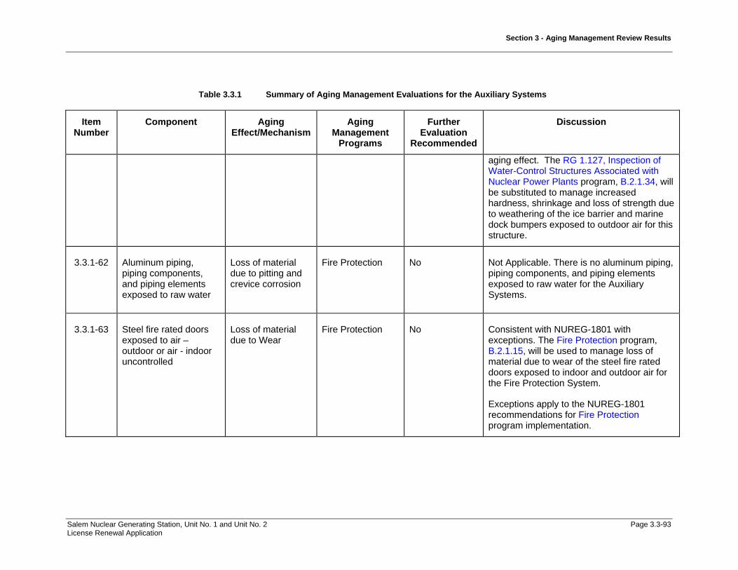
Section 3 - Aging Management Review Results
Salem Nuclear Generating Station, Unit No. 1 and Unit No. 2 Page 3.3-93 License Renewal Application
Table 3.3.1 Summary of Aging Management Evaluations for the Auxiliary Systems
Item Number
Component Aging Effect/Mechanism
Aging Management
Programs
Further Evaluation
Recommended
Discussion
aging effect. The RG 1.127, Inspection of Water-Control Structures Associated with Nuclear Power Plants program, B.2.1.34, will be substituted to manage increased hardness, shrinkage and loss of strength due to weathering of the ice barrier and marine dock bumpers exposed to outdoor air for this structure.
3.3.1-62 Aluminum piping, piping components, and piping elements exposed to raw water
Loss of material due to pitting and crevice corrosion
Fire Protection No Not Applicable. There is no aluminum piping, piping components, and piping elements exposed to raw water for the Auxiliary Systems.
3.3.1-63 Steel fire rated doors exposed to air – outdoor or air - indoor uncontrolled
Loss of material due to Wear
Fire Protection No Consistent with NUREG-1801 with exceptions. The Fire Protection program, B.2.1.15, will be used to manage loss of material due to wear of the steel fire rated doors exposed to indoor and outdoor air for the Fire Protection System.
Exceptions apply to the NUREG-1801 recommendations for Fire Protection program implementation.

Section 3 - Aging Management Review Results
Salem Nuclear Generating Station, Unit No. 1 and Unit No. 2 Page 3.3-94 License Renewal Application
Table 3.3.1 Summary of Aging Management Evaluations for the Auxiliary Systems
Item Number
Component Aging Effect/Mechanism
Aging Management
Programs
Further Evaluation
Recommended
Discussion
3.3.1-64 Steel piping, piping components, and piping elements exposed to fuel oil
Loss of material due to general, pitting, and crevice corrosion
Fire Protection and Fuel Oil Chemistry
No Not Applicable. This component, material, environment, and aging effect/mechanism does not apply to Auxiliary Systems.
AMR methodology for steel piping, piping components, and piping elements exposed to fuel oil includes the additional aging mechanisms of Microbiological-Influenced Corrosion (MIC) and Fouling. This component, material, environment, and aging effect/mechanism combination is addressed in Item Number 3.3.1-20.
3.3.1-65 Reinforced concrete structural fire barriers – walls, ceilings and floors exposed to air – indoor uncontrolled
Concrete cracking and spalling due to aggressive chemical attack, and reaction with aggregates
Fire Protection and Structures Monitoring Program
No Not Applicable. This component, material, environment, and aging effect/mechanism does not apply to Auxiliary Systems.
These aging effects and environments are addressed in section 3.5 for the appropriate buildings.

Section 3 - Aging Management Review Results
Salem Nuclear Generating Station, Unit No. 1 and Unit No. 2 Page 3.3-95 License Renewal Application
Table 3.3.1 Summary of Aging Management Evaluations for the Auxiliary Systems
Item Number
Component Aging Effect/Mechanism
Aging Management
Programs
Further Evaluation
Recommended
Discussion
3.3.1-66 Reinforced concrete structural fire barriers – walls, ceilings and floors exposed to air – outdoor
Concrete cracking and spalling due to freeze thaw, aggressive chemical attack, and reaction with aggregates
Fire Protection and Structures Monitoring Program
No Consistent with NUREG-1801 with exceptions. The Fire Protection program, B.2.1.15, and Structures Monitoring program, B.2.1.33, will be used to manage concrete cracking and spalling due to freeze thaw of the reinforced concrete structural fire barriers walls, ceilings, and floors exposed to outdoor air for the Fire Protection System.
Exceptions apply to the NUREG-1801 recommendations for Fire Protection program implementation.
3.3.1-67 Reinforced concrete structural fire barriers – walls, ceilings and floors exposed to air – outdoor or air - indoor uncontrolled
Loss of material due to corrosion of embedded steel
Fire Protection and Structures Monitoring Program
No Consistent with NUREG-1801 with exceptions. The Fire Protection, B.2.1.15, and Structures Monitoring, B.2.1.33, programs will be used to manage loss of material due to corrosion of embedded steel of the reinforced concrete structural fire barriers walls, ceilings, and floors exposed to indoor or outdoor air for the Fire Protection System.
Exceptions apply to the NUREG-1801 recommendations for Fire Protection program implementation.
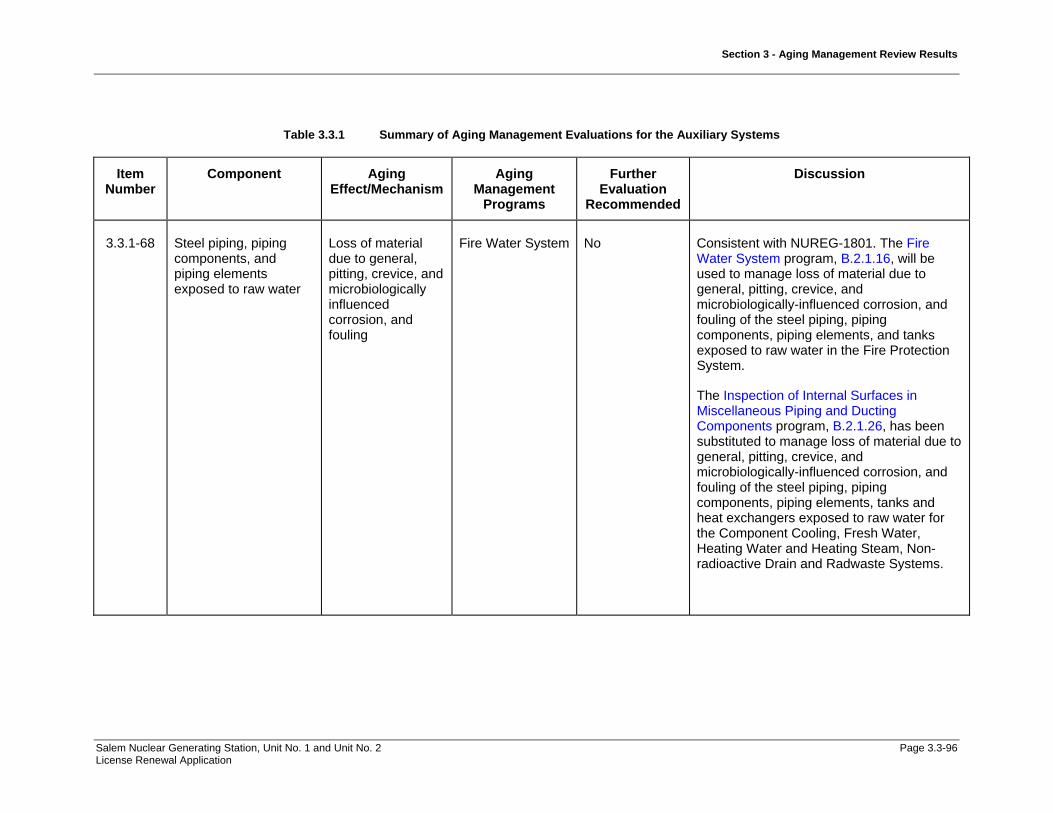
Section 3 - Aging Management Review Results
Salem Nuclear Generating Station, Unit No. 1 and Unit No. 2 Page 3.3-96 License Renewal Application
Table 3.3.1 Summary of Aging Management Evaluations for the Auxiliary Systems
Item Number
Component Aging Effect/Mechanism
Aging Management
Programs
Further Evaluation
Recommended
Discussion
3.3.1-68 Steel piping, piping components, and piping elements exposed to raw water
Loss of material due to general, pitting, crevice, and microbiologically influenced corrosion, and fouling
Fire Water System No Consistent with NUREG-1801. The Fire Water System program, B.2.1.16, will be used to manage loss of material due to general, pitting, crevice, and microbiologically-influenced corrosion, and fouling of the steel piping, piping components, piping elements, and tanks exposed to raw water in the Fire Protection System.
The Inspection of Internal Surfaces in Miscellaneous Piping and Ducting Components program, B.2.1.26, has been substituted to manage loss of material due to general, pitting, crevice, and microbiologically-influenced corrosion, and fouling of the steel piping, piping components, piping elements, tanks and heat exchangers exposed to raw water for the Component Cooling, Fresh Water, Heating Water and Heating Steam, Non-radioactive Drain and Radwaste Systems.

Section 3 - Aging Management Review Results
Salem Nuclear Generating Station, Unit No. 1 and Unit No. 2 Page 3.3-97 License Renewal Application
Table 3.3.1 Summary of Aging Management Evaluations for the Auxiliary Systems
Item Number
Component Aging Effect/Mechanism
Aging Management
Programs
Further Evaluation
Recommended
Discussion
3.3.1-69 Stainless steel piping, piping components, and piping elements exposed to raw water
Loss of material due to pitting and crevice corrosion, and fouling
Fire Water System No Not Applicable. This component, material, environment, and aging effect/mechanism does not apply to Auxiliary Systems.
AMR methodology for stainless steel piping, piping components, and piping elements exposed to raw water requires the prediction of microbiological-influenced corrosion aging effect/mechanism. The Fire Protection System stainless steel piping components and piping elements exposed to raw water are included in Item Number 3.4.1-33.

Section 3 - Aging Management Review Results
Salem Nuclear Generating Station, Unit No. 1 and Unit No. 2 Page 3.3-98 License Renewal Application
Table 3.3.1 Summary of Aging Management Evaluations for the Auxiliary Systems
Item Number
Component Aging Effect/Mechanism
Aging Management
Programs
Further Evaluation
Recommended
Discussion
3.3.1-70 Copper alloy piping, piping components, and piping elements exposed to raw water
Loss of material due to pitting, crevice, and microbiologically influenced corrosion, and fouling
Fire Water System No Consistent with NUREG-1801. The Fire Water System program, B.2.1.16, will be used to manage loss of material due to pitting, crevice, and microbiologically-influenced corrosion, and fouling of the copper alloy piping, piping components, and piping elements exposed to raw water for the Fire Protection System.
Components in the Non-radioactive Drain System and Radioactive Drain System have been aligned to this item number based on material, environment and aging effect. The Periodic Inspection program, B.2.2.2, will be substituted to manage loss of material due to pitting, crevice, and microbiologically-influenced corrosion, and fouling of the copper alloy piping, piping components, and piping elements for these systems.
3.3.1-71 Steel piping, piping components, and piping elements exposed to moist air or condensation (Internal)
Loss of material due to general, pitting, and crevice corrosion
Inspection of Internal Surfaces in Miscellaneous Piping and Ducting Components
No Consistent with NUREG-1801. The Inspection of Internal Surfaces in Miscellaneous Piping and Ducting Components program, B.2.1.26, will be used to manage loss of material due to general, pitting, and crevice corrosion of the steel piping, piping components, piping elements, heat exchanger components, and tanks exposed to air/gas-wetted for the Chilled

Section 3 - Aging Management Review Results
Salem Nuclear Generating Station, Unit No. 1 and Unit No. 2 Page 3.3-99 License Renewal Application
Table 3.3.1 Summary of Aging Management Evaluations for the Auxiliary Systems
Item Number
Component Aging Effect/Mechanism
Aging Management
Programs
Further Evaluation
Recommended
Discussion
Water System, Component Cooling, Containment Ventilation System, Emergency Diesel Generators & Auxiliaries System, Fuel Oil System, Radioactive Drain System, Radwaste System, Service Water System, and Switchgear and Penetration Area Ventilation System.
Components in the Compressed Air System have been aligned to this item number based on material, environment and aging effect. The Compressed Air Monitoring program, B.2.1.14, will be substituted to manage loss of material due to general, pitting, and crevice corrosion of the steel piping, piping components, piping elements, and tanks for this system.
Components in the Fire Protection System have been aligned to this item number based on material, environment and aging effect. The Fire Protection program, B.2.1.15, and Fire Water System, B.2.1.16, will be substituted to manage loss of material due to general, pitting, and crevice corrosion of the steel piping, piping components, and piping elements for this system.

Section 3 - Aging Management Review Results
Salem Nuclear Generating Station, Unit No. 1 and Unit No. 2 Page 3.3-100 License Renewal Application
Table 3.3.1 Summary of Aging Management Evaluations for the Auxiliary Systems
Item Number
Component Aging Effect/Mechanism
Aging Management
Programs
Further Evaluation
Recommended
Discussion
3.3.1-72 Steel HVAC ducting and components internal surfaces exposed to condensation (Internal)
Loss of material due to general, pitting, crevice, and (for drip pans and drain lines) microbiologically influenced corrosion
Inspection of Internal Surfaces in Miscellaneous Piping and Ducting Components
No Consistent with NUREG-1801. The Inspection of Internal Surfaces in Miscellaneous Piping and Ducting Components program, B.2.1.26, will be used to manage loss of material due to general, pitting, and crevice and (for drip pans and drain lines) microbiological-influenced corrosion of the steel HVAC ducting and components internal surfaces exposed to air/gas - wetted for the Auxiliary Building Ventilation System, Containment Ventilation System, Control Area Ventilation System, Fuel Handling Ventilation System, Service Water Ventilation System and Switchgear and Penetration Area Ventilation System.
Components in the Fire Protection System have been aligned to this item number based on material, environment and aging effect. The Fire Protection program, B.2.1.15, will be substituted to manage general, pitting, and crevice corrosion of the steel HVAC ducting and components internal surfaces exposed to air/gas - wetted air for this system.
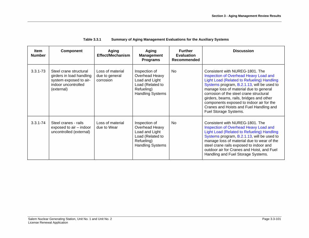
Section 3 - Aging Management Review Results
Salem Nuclear Generating Station, Unit No. 1 and Unit No. 2 Page 3.3-101 License Renewal Application
Table 3.3.1 Summary of Aging Management Evaluations for the Auxiliary Systems
Item Number
Component Aging Effect/Mechanism
Aging Management
Programs
Further Evaluation
Recommended
Discussion
3.3.1-73 Steel crane structural girders in load handling system exposed to air- indoor uncontrolled (external)
Loss of material due to general corrosion
Inspection of Overhead Heavy Load and Light Load (Related to Refueling) Handling Systems
No Consistent with NUREG-1801. The Inspection of Overhead Heavy Load and Light Load (Related to Refueling) Handling Systems program, B.2.1.13, will be used to manage loss of material due to general corrosion of the steel crane structural girders, beams, rails, bridges and other components exposed to indoor air for the Cranes and Hoists and Fuel Handling and Fuel Storage Systems.
3.3.1-74 Steel cranes - rails exposed to air – indoor uncontrolled (external)
Loss of material due to Wear
Inspection of Overhead Heavy Load and Light Load (Related to Refueling) Handling Systems
No Consistent with NUREG-1801. The Inspection of Overhead Heavy Load and Light Load (Related to Refueling) Handling Systems program, B.2.1.13, will be used to manage loss of material due to wear of the steel crane rails exposed to indoor and outdoor air for Cranes and Hoist, and Fuel Handling and Fuel Storage Systems.

Section 3 - Aging Management Review Results
Salem Nuclear Generating Station, Unit No. 1 and Unit No. 2 Page 3.3-102 License Renewal Application
Table 3.3.1 Summary of Aging Management Evaluations for the Auxiliary Systems
Item Number
Component Aging Effect/Mechanism
Aging Management
Programs
Further Evaluation
Recommended
Discussion
3.3.1-75 Elastomer seals and components exposed to raw water
Hardening and loss of strength due to elastomer degradation; loss of material due to erosion
Open-Cycle Cooling Water System
No Consistent with NUREG-1801. The Open Cycle Cooling Water System program, B.2.1.11, will be used to manage loss of strength due to elastomer degradation and the loss of material due to erosion of the elastomer piping and fitting components exposed to raw water for the Service Water System.
Components in the Service Water Intake structure program have been aligned to this item number based on material, environment and aging effect. The RG 1.127, Inspection of Water-Control Structures Associated with Nuclear Power Plants program, B.2.1.34, will be substituted to manage hardening and loss of strength due to degradation of the elastomer for the ice barrier and marine dock bumpers for this structure.
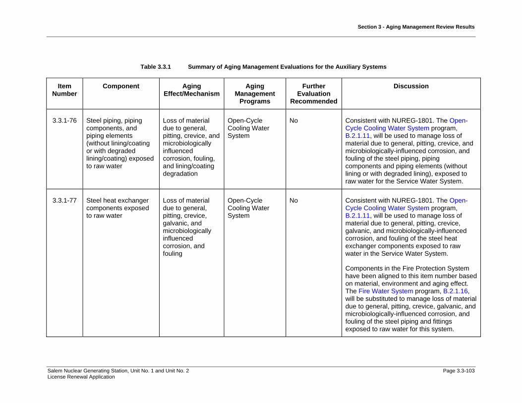
Section 3 - Aging Management Review Results
Salem Nuclear Generating Station, Unit No. 1 and Unit No. 2 Page 3.3-103 License Renewal Application
Table 3.3.1 Summary of Aging Management Evaluations for the Auxiliary Systems
Item Number
Component Aging Effect/Mechanism
Aging Management
Programs
Further Evaluation
Recommended
Discussion
3.3.1-76 Steel piping, piping components, and piping elements (without lining/coating or with degraded lining/coating) exposed to raw water
Loss of material due to general, pitting, crevice, and microbiologically influenced corrosion, fouling, and lining/coating degradation
Open-Cycle Cooling Water System
No Consistent with NUREG-1801. The Open-Cycle Cooling Water System program, B.2.1.11, will be used to manage loss of material due to general, pitting, crevice, and microbiologically-influenced corrosion, and fouling of the steel piping, piping components and piping elements (without lining or with degraded lining), exposed to raw water for the Service Water System.
3.3.1-77 Steel heat exchanger components exposed to raw water
Loss of material due to general, pitting, crevice, galvanic, and microbiologically influenced corrosion, and fouling
Open-Cycle Cooling Water System
No Consistent with NUREG-1801. The Open-Cycle Cooling Water System program, B.2.1.11, will be used to manage loss of material due to general, pitting, crevice, galvanic, and microbiologically-influenced corrosion, and fouling of the steel heat exchanger components exposed to raw water in the Service Water System.
Components in the Fire Protection System have been aligned to this item number based on material, environment and aging effect. The Fire Water System program, B.2.1.16, will be substituted to manage loss of material due to general, pitting, crevice, galvanic, and microbiologically-influenced corrosion, and fouling of the steel piping and fittings exposed to raw water for this system.

Section 3 - Aging Management Review Results
Salem Nuclear Generating Station, Unit No. 1 and Unit No. 2 Page 3.3-104 License Renewal Application
Table 3.3.1 Summary of Aging Management Evaluations for the Auxiliary Systems
Item Number
Component Aging Effect/Mechanism
Aging Management
Programs
Further Evaluation
Recommended
Discussion
Components in the Heating Water and Heating Steam System have been aligned to this item number based on material, environment and aging effect. The Inspection of Internal Surfaces in Miscellaneous Piping and Ducting Components program, B.2.1.26, will be substituted to manage the loss of material due to general, pitting, crevice, galvanic, and microbiologically-influenced corrosion, and fouling of the steel piping and fittings exposed to raw water for this system.
3.3.1-78 Stainless steel, nickel alloy, and copper alloy piping, piping components, and piping elements exposed to raw water
Loss of material due to pitting and crevice corrosion
Open-Cycle Cooling Water System
No Not Applicable. The AMR methodology for stainless steel, nickel alloy, and copper alloy piping, piping components, and piping elements exposed to raw water requires the prediction of Microbiological-Influenced Corrosion (MIC) for this aging mechanism which is not addressed in this item number. These are evaluated in Item Number 3.3.1-80.

Section 3 - Aging Management Review Results
Salem Nuclear Generating Station, Unit No. 1 and Unit No. 2 Page 3.3-105 License Renewal Application
Table 3.3.1 Summary of Aging Management Evaluations for the Auxiliary Systems
Item Number
Component Aging Effect/Mechanism
Aging Management
Programs
Further Evaluation
Recommended
Discussion
3.3.1-79 Stainless steel piping, piping components, and piping elements exposed to raw water
Loss of material due to pitting and crevice corrosion, and fouling
Open-Cycle Cooling Water System
No Not Applicable. The component, material, environment, and aging effect combination does not apply to stainless steel materials exposed to raw water in the Auxiliary Systems.
The AMR methodology for stainless steel piping, piping components, and piping elements exposed to raw water requires the prediction of Microbiological-Influenced Corrosion (MIC) for this aging mechanism, which is not addressed in this item number. These are evaluated in Table 3.4.1, Item Number 3.4.1-33.
3.3.1-80 Stainless steel and copper alloy piping, piping components, and piping elements exposed to raw water
Loss of material due to pitting, crevice, and microbiologically influenced corrosion
Open-Cycle Cooling Water System
No Components in the Component Cooling System, Heating Water and Heating Steam System and Radwaste System have been aligned to this item number based on material, environment and aging effect. The Periodic Inspection program, B.2.2.2, will be substituted to manage loss of material due to pitting, crevice, and microbiologically-induced corrosion of the stainless steel piping, piping components, and piping elements exposed to raw water for these systems.
Components in the Auxiliary Building, Containment Structure, and Service Water
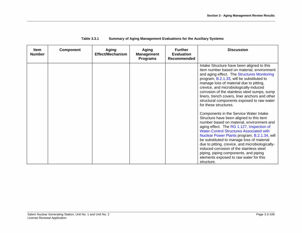
Section 3 - Aging Management Review Results
Salem Nuclear Generating Station, Unit No. 1 and Unit No. 2 Page 3.3-106 License Renewal Application
Table 3.3.1 Summary of Aging Management Evaluations for the Auxiliary Systems
Item Number
Component Aging Effect/Mechanism
Aging Management
Programs
Further Evaluation
Recommended
Discussion
Intake Structure have been aligned to this item number based on material, environment and aging effect. The Structures Monitoring program, B.2.1.33, will be substituted to manage loss of material due to pitting, crevice, and microbiologically-induced corrosion of the stainless steel sumps, sump liners, trench covers, liner anchors and other structural components exposed to raw water for these structures.
Components in the Service Water Intake Structure have been aligned to this item number based on material, environment and aging effect. The RG 1.127, Inspection of Water-Control Structures Associated with Nuclear Power Plants program, B.2.1.34, will be substituted to manage loss of material due to pitting, crevice, and microbiologically-induced corrosion of the stainless steel piping, piping components, and piping elements exposed to raw water for this structure.
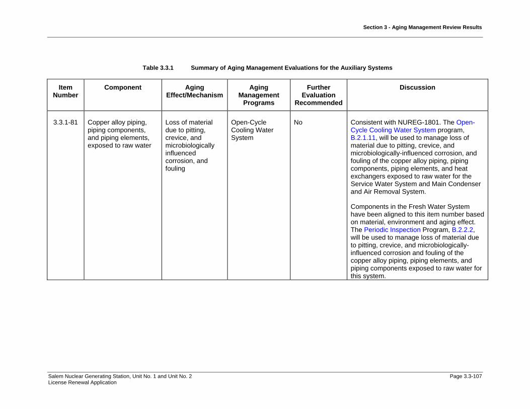
Section 3 - Aging Management Review Results
Salem Nuclear Generating Station, Unit No. 1 and Unit No. 2 Page 3.3-107 License Renewal Application
Table 3.3.1 Summary of Aging Management Evaluations for the Auxiliary Systems
Item Number
Component Aging Effect/Mechanism
Aging Management
Programs
Further Evaluation
Recommended
Discussion
3.3.1-81 Copper alloy piping, piping components, and piping elements, exposed to raw water
Loss of material due to pitting, crevice, and microbiologically influenced corrosion, and fouling
Open-Cycle Cooling Water System
No Consistent with NUREG-1801. The Open-Cycle Cooling Water System program, B.2.1.11, will be used to manage loss of material due to pitting, crevice, and microbiologically-influenced corrosion, and fouling of the copper alloy piping, piping components, piping elements, and heat exchangers exposed to raw water for the Service Water System and Main Condenser and Air Removal System.
Components in the Fresh Water System have been aligned to this item number based on material, environment and aging effect. The Periodic Inspection Program, B.2.2.2, will be used to manage loss of material due to pitting, crevice, and microbiologically-influenced corrosion and fouling of the copper alloy piping, piping elements, and piping components exposed to raw water for this system.
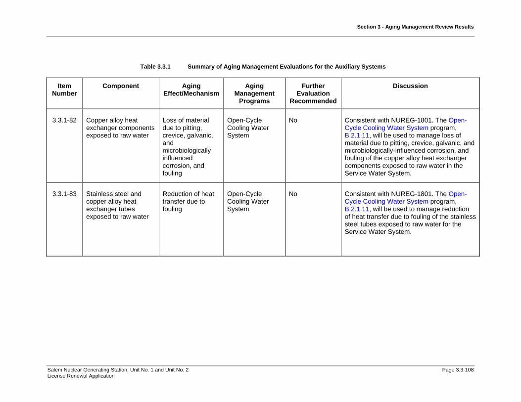
Section 3 - Aging Management Review Results
Salem Nuclear Generating Station, Unit No. 1 and Unit No. 2 Page 3.3-108 License Renewal Application
Table 3.3.1 Summary of Aging Management Evaluations for the Auxiliary Systems
Item Number
Component Aging Effect/Mechanism
Aging Management
Programs
Further Evaluation
Recommended
Discussion
3.3.1-82 Copper alloy heat exchanger components exposed to raw water
Loss of material due to pitting, crevice, galvanic, and microbiologically influenced corrosion, and fouling
Open-Cycle Cooling Water System
No Consistent with NUREG-1801. The Open-Cycle Cooling Water System program, B.2.1.11, will be used to manage loss of material due to pitting, crevice, galvanic, and microbiologically-influenced corrosion, and fouling of the copper alloy heat exchanger components exposed to raw water in the Service Water System.
3.3.1-83 Stainless steel and copper alloy heat exchanger tubes exposed to raw water
Reduction of heat transfer due to fouling
Open-Cycle Cooling Water System
No Consistent with NUREG-1801. The Open-Cycle Cooling Water System program, B.2.1.11, will be used to manage reduction of heat transfer due to fouling of the stainless steel tubes exposed to raw water for the Service Water System.

Section 3 - Aging Management Review Results
Salem Nuclear Generating Station, Unit No. 1 and Unit No. 2 Page 3.3-109 License Renewal Application
Table 3.3.1 Summary of Aging Management Evaluations for the Auxiliary Systems
Item Number
Component Aging Effect/Mechanism
Aging Management
Programs
Further Evaluation
Recommended
Discussion
3.3.1-84 Copper alloy >15% Zn piping, piping components, piping elements, and heat exchanger components exposed to raw water, treated water, or closed cycle cooling water
Loss of material due to selective leaching
Selective Leaching of Materials
No Consistent with NUREG-1801. The Selective Leaching of Materials program, B.2.1.21, will be used to manage loss of material due to selective leaching of the copper alloy with greater than 15% zinc piping, piping components, piping and fittings, and heat exchanger components exposed to raw water, closed cycle cooling water or treated water in the Component Cooling System, Emergency Diesel Generators & Auxiliaries System, Fire Protection System, Fresh Water System, and Service Water System.
3.3.1-85 Gray cast iron piping, piping components, and piping elements exposed to soil, raw water, treated water, or closed-cycle cooling water
Loss of material due to selective leaching
Selective Leaching of Materials
No Consistent with NUREG-1801. The Selective Leaching of Materials program, B.2.1.21, will be used to manage loss of material due to selective leaching of the gray cast iron piping, piping components, piping elements, tanks, fire hydrants, and heat exchanger components exposed to soil, raw water, or closed-cycle cooling water in the Chilled Water System, Fire Protection System, Heating Water and Heating Steam System, and Service Water System.

Section 3 - Aging Management Review Results
Salem Nuclear Generating Station, Unit No. 1 and Unit No. 2 Page 3.3-110 License Renewal Application
Table 3.3.1 Summary of Aging Management Evaluations for the Auxiliary Systems
Item Number
Component Aging Effect/Mechanism
Aging Management
Programs
Further Evaluation
Recommended
Discussion
3.3.1-86 Structural steel (new fuel storage rack assembly) exposed to air – indoor uncontrolled (external)
Loss of material due to general, pitting, and crevice corrosion
Structures Monitoring Program
No Not Applicable. The component, material, environment, and aging effect combination does not apply to structural steel (new fuel rack storage assembly) materials exposed to indoor air in the Auxiliary Systems.
AMR methodology for steel (new fuel storage rack assembly) does not predict loss of material due to pitting and crevice corrosion. This component, material, environment, and aging effect/mechanism combination is addressed in Item Number 3.3.1-58.
3.3.1-87 Boraflex spent fuel storage racks neutron-absorbing sheets exposed to treated borated water
Reduction of neutron-absorbing capacity due to boraflex degradation
Boraflex Monitoring
No Not Applicable. There are no boraflex spent fuel storage racks neutron-absorbing sheets exposed to treated borated water in the Auxiliary Systems. The Salem spent fuel storage racks are Boral and are addressed by Item Number 3.3.1-13.

Section 3 - Aging Management Review Results
Salem Nuclear Generating Station, Unit No. 1 and Unit No. 2 Page 3.3-111 License Renewal Application
Table 3.3.1 Summary of Aging Management Evaluations for the Auxiliary Systems
Item Number
Component Aging Effect/Mechanism
Aging Management
Programs
Further Evaluation
Recommended
Discussion
3.3.1-88 Aluminum and copper alloy >15% Zn piping, piping components, and piping elements exposed to air with borated water leakage
Loss of material due to Boric acid corrosion
Boric Acid Corrosion
No Consistent with NUREG-1801. The Boric Acid Corrosion program, B.2.1.4, will be used to manage loss of material due to boric acid corrosion of the aluminum and copper alloy >15% Zn piping, piping components, piping elements, fire barriers (wraps), and fuel storage racks (new fuel) exposed to air with borated water leakage in the Auxiliary Building Ventilation System, Chilled Water System, Component Cooling System, Compressed Air System, Fire Protection System, Fresh Water System, Fuel Handling & Fuel Storage System and Heating Water and Heating Steam System.
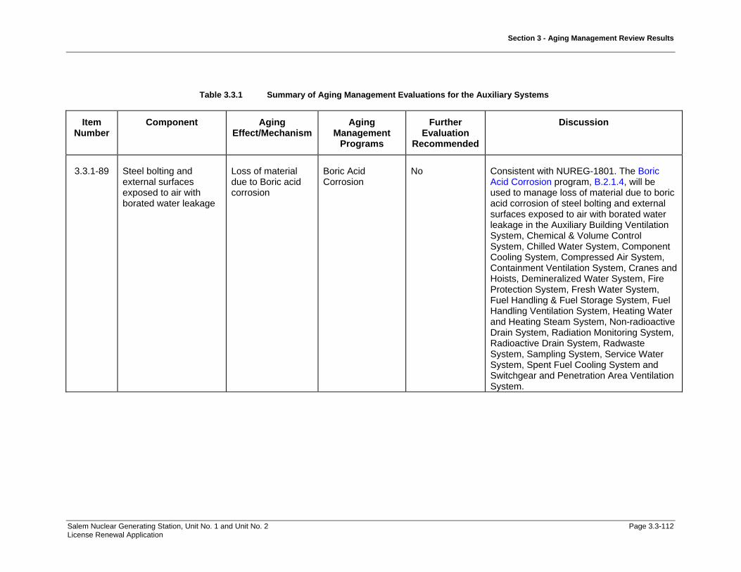
Section 3 - Aging Management Review Results
Salem Nuclear Generating Station, Unit No. 1 and Unit No. 2 Page 3.3-112 License Renewal Application
Table 3.3.1 Summary of Aging Management Evaluations for the Auxiliary Systems
Item Number
Component Aging Effect/Mechanism
Aging Management
Programs
Further Evaluation
Recommended
Discussion
3.3.1-89 Steel bolting and external surfaces exposed to air with borated water leakage
Loss of material due to Boric acid corrosion
Boric Acid Corrosion
No Consistent with NUREG-1801. The Boric Acid Corrosion program, B.2.1.4, will be used to manage loss of material due to boric acid corrosion of steel bolting and external surfaces exposed to air with borated water leakage in the Auxiliary Building Ventilation System, Chemical & Volume Control System, Chilled Water System, Component Cooling System, Compressed Air System, Containment Ventilation System, Cranes and Hoists, Demineralized Water System, Fire Protection System, Fresh Water System, Fuel Handling & Fuel Storage System, Fuel Handling Ventilation System, Heating Water and Heating Steam System, Non-radioactive Drain System, Radiation Monitoring System, Radioactive Drain System, Radwaste System, Sampling System, Service Water System, Spent Fuel Cooling System and Switchgear and Penetration Area Ventilation System.
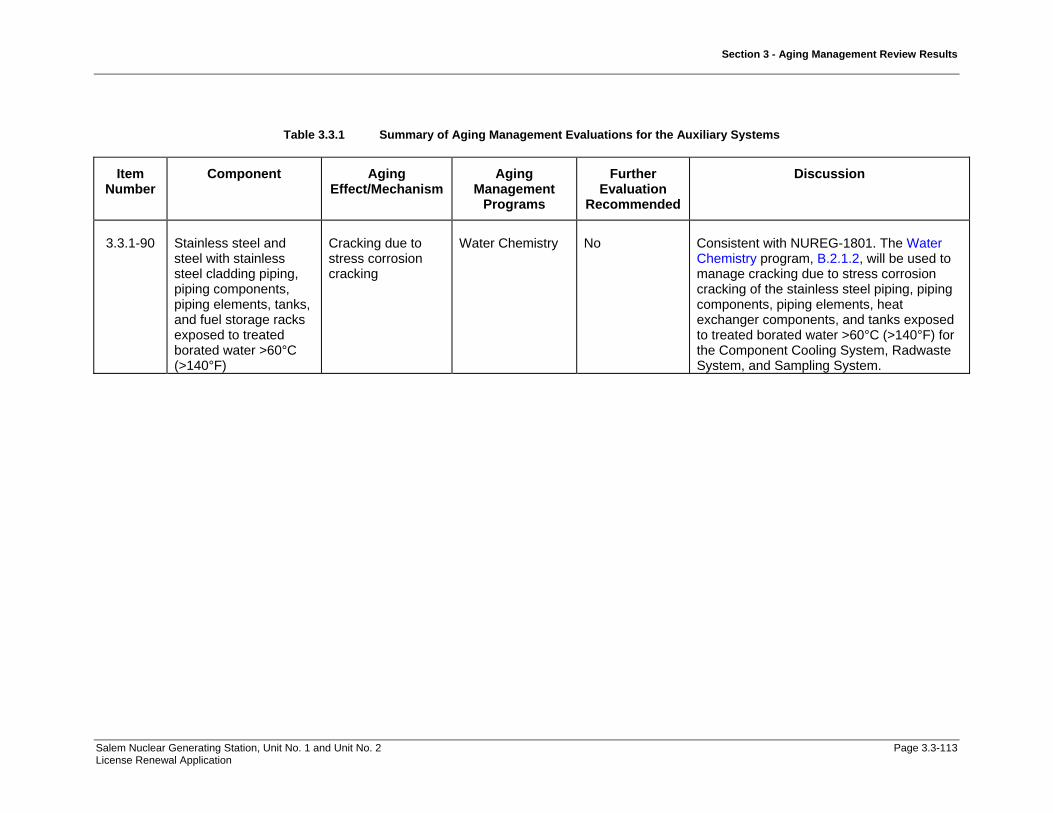
Section 3 - Aging Management Review Results
Salem Nuclear Generating Station, Unit No. 1 and Unit No. 2 Page 3.3-113 License Renewal Application
Table 3.3.1 Summary of Aging Management Evaluations for the Auxiliary Systems
Item Number
Component Aging Effect/Mechanism
Aging Management
Programs
Further Evaluation
Recommended
Discussion
3.3.1-90 Stainless steel and steel with stainless steel cladding piping, piping components, piping elements, tanks, and fuel storage racks exposed to treated borated water >60°C (>140°F)
Cracking due to stress corrosion cracking
Water Chemistry No Consistent with NUREG-1801. The Water Chemistry program, B.2.1.2, will be used to manage cracking due to stress corrosion cracking of the stainless steel piping, piping components, piping elements, heat exchanger components, and tanks exposed to treated borated water >60°C (>140°F) for the Component Cooling System, Radwaste System, and Sampling System.

Section 3 - Aging Management Review Results
Salem Nuclear Generating Station, Unit No. 1 and Unit No. 2 Page 3.3-114 License Renewal Application
Table 3.3.1 Summary of Aging Management Evaluations for the Auxiliary Systems
Item Number
Component Aging Effect/Mechanism
Aging Management
Programs
Further Evaluation
Recommended
Discussion
3.3.1-91 Stainless steel and steel with stainless steel cladding piping, piping components, and piping elements exposed to treated borated water
Loss of material due to pitting and crevice corrosion
Water Chemistry No Consistent with NUREG-1801. The Water Chemistry program, B.2.1.2, will be used to manage loss of material due to pitting and crevice corrosion of the stainless steel and steel with stainless steel cladding piping, piping components, piping elements, heat exchanger components, cranes and hoists, fuel storage racks, tanks, liners, penetration bellows and other structural components exposed to treated borated water for the Chemical & Volume Control System, Component Cooling System, Fuel Handling and Fuel Storage System, Radwaste System, Sampling System, Spent Fuel Cooling System, Component Supports Commodity Group, Containment Structure, and Fuel Handling Building.
Components in the Component Supports Commodity Group have been aligned to this item number based upon material, environment and aging effect. The ASME Section XI, Subsection IWF program, B.2.1.30, will be added to manage loss of material due to pitting and crevice corrosion for the support members, welds, bolted connections, and support anchorages to building structure for the Component Supports Commodity Group.

Section 3 - Aging Management Review Results
Salem Nuclear Generating Station, Unit No. 1 and Unit No. 2 Page 3.3-115 License Renewal Application
Table 3.3.1 Summary of Aging Management Evaluations for the Auxiliary Systems
Item Number
Component Aging Effect/Mechanism
Aging Management
Programs
Further Evaluation
Recommended
Discussion
3.3.1-92 Galvanized steel piping, piping components, and piping elements exposed to air – indoor uncontrolled
None None NA - No AEM or AMP
Consistent with NUREG-1801.
3.3.1-93 Glass piping elements exposed to air, air – indoor uncontrolled (external), fuel oil, lubricating oil, raw water, treated water, and treated borated water
None None NA - No AEM or AMP
Consistent with NUREG-1801.
3.3.1-94 Stainless steel and nickel alloy piping, piping components, and piping elements exposed to air – indoor uncontrolled (external)
None None NA - No AEM or AMP
Consistent with NUREG-1801.

Section 3 - Aging Management Review Results
Salem Nuclear Generating Station, Unit No. 1 and Unit No. 2 Page 3.3-116 License Renewal Application
Table 3.3.1 Summary of Aging Management Evaluations for the Auxiliary Systems
Item Number
Component Aging Effect/Mechanism
Aging Management
Programs
Further Evaluation
Recommended
Discussion
3.3.1-95 Steel and aluminum piping, piping components, and piping elements exposed to air – indoor controlled (external)
None None NA - No AEM or AMP
Not Applicable.
All indoor air environments at Salem are assumed to be uncontrolled for license renewal.
3.3.1-96 Steel and stainless steel piping, piping components, and piping elements in concrete
None None NA - No AEM or AMP
Consistent with NUREG-1801.
3.3.1-97 Steel, stainless steel, aluminum, and copper alloy piping, piping components, and piping elements exposed to gas
None None NA - No AEM or AMP
Consistent with NUREG-1801.
3.3.1-98 Steel, stainless steel, and copper alloy piping, piping components, and piping elements exposed to dried air
None None NA - No AEM or AMP
The Compressed Air Monitoring program, B.2.1.14, will be used to preclude aging effects for steel, stainless steel, and copper alloy piping, piping components, and piping elements in the Compressed Air System by maintaining dry air conditions in the system.

Section 3 - Aging Management Review Results
Salem Nuclear Generating Station, Unit No. 1 and Unit No. 2 Page 3.3-117 License Renewal Application
Table 3.3.1 Summary of Aging Management Evaluations for the Auxiliary Systems
Item Number
Component Aging Effect/Mechanism
Aging Management
Programs
Further Evaluation
Recommended
Discussion
3.3.1-99 Stainless steel and copper alloy <15% Zn piping, piping components, and piping elements exposed to air with borated water leakage
None None NA - No AEM or AMP
Consistent with NUREG-1801.

Section 3 - Aging Management Review Results
Salem Nuclear Generating Station, Unit No. 1 and Unit No. 2 Page 3.3-118 License Renewal Application
Table 3.3.2-1 Auxiliary Building Ventilation System
Summary of Aging Management Evaluation
Table 3.3.2-1 Auxiliary Building Ventilation System
Component Type
Intended Function
Material Environment Aging Effect Requiring
Management
Aging Management Programs
NUREG-1801 Vol. 2 Item
Table 1 Item Notes
Bolting Mechanical Closure Carbon and Low Alloy Steel
Bolting
Air - Indoor (External) Loss of Material/General Corrosion
External Surfaces Monitoring
VII.I-7 3.3.1-55 A
Bolting Mechanical Closure Carbon and Low Alloy Steel
Bolting
Air - Indoor (External) Loss of Material/General, Pitting and Crevice
Corrosion
Bolting Integrity VII.I-4 3.3.1-43 B
Bolting Mechanical Closure Carbon and Low Alloy Steel
Bolting
Air with Borated Water Leakage (External)
Loss of Material/Boric Acid Corrosion
Boric Acid Corrosion VII.I-2 3.3.1-89 A
Damper Housing Pressure Boundary Galvanized Steel Air - Indoor (External) None None VII.J-6 3.3.1-92 C Damper Housing Pressure Boundary Galvanized Steel Air with Borated Water
Leakage (External) Loss of Material/Boric Acid
Corrosion Boric Acid Corrosion VII.I-10 3.3.1-89 A
Damper Housing Pressure Boundary Galvanized Steel Air/Gas - Wetted (Internal)
Loss of Material/General, Pitting and Crevice
Corrosion
Inspection of Internal Surfaces in Miscellaneous
Piping and Ducting Components
VII.F2-3 3.3.1-72 A
Door Seals Pressure Boundary Elastomer Air - Indoor (External) Hardening and Loss of Strength/Elastomer
Degradation
Periodic Inspection VII.F2-7 3.3.1-11 E, 2
Door Seals Pressure Boundary Elastomer Air with Borated Water Leakage (External)
None None G, 3
Door Seals Pressure Boundary Elastomer Air/Gas - Wetted (Internal)
Hardening and Loss of Strength/Elastomer
Degradation
Periodic Inspection G
Ducting and Components
Pressure Boundary Galvanized Steel Air - Indoor (External) None None VII.J-6 3.3.1-92 C

Section 3 - Aging Management Review Results
Salem Nuclear Generating Station, Unit No. 1 and Unit No. 2 Page 3.3-119 License Renewal Application
Table 3.3.2-1 Auxiliary Building Ventilation System (Continued)
Component Type
Intended Function
Material Environment Aging Effect Requiring
Management
Aging Management Programs
NUREG-1801 Vol. 2 Item
Table 1 Item Notes
Ducting and Components
Pressure Boundary Galvanized Steel Air - Outdoor (External) Loss of Material/General, Pitting and Crevice
Corrosion
External Surfaces Monitoring
VII.H1-8 3.3.1-60 C
Ducting and Components
Pressure Boundary Galvanized Steel Air with Borated Water Leakage (External)
Loss of Material/Boric Acid Corrosion
Boric Acid Corrosion VII.I-10 3.3.1-89 A
Ducting and Components
Pressure Boundary Galvanized Steel Air/Gas - Wetted (Internal)
Loss of Material/General, Pitting and Crevice
Corrosion
Inspection of Internal Surfaces in Miscellaneous
Piping and Ducting Components
VII.F2-3 3.3.1-72 A
Ducting and Components
Pressure Boundary Galvanized Steel Concrete None None VII.J-21 3.3.1-96 C
Ducting and Components
Pressure Boundary Stainless Steel Air - Indoor (External) None None VII.J-15 3.3.1-94 C
Ducting and Components
Pressure Boundary Stainless Steel Air with Borated Water Leakage (External)
None None VII.J-16 3.3.1-99 C
Ducting and Components
Pressure Boundary Stainless Steel Air/Gas - Wetted (Internal)
Loss of Material/Pitting and Crevice Corrosion
Periodic Inspection VII.F2-1 3.3.1-27 E, 2
Fan Housing Pressure Boundary Galvanized Steel Air - Indoor (External) None None VII.J-6 3.3.1-92 C Fan Housing Pressure Boundary Galvanized Steel Air with Borated Water
Leakage (External) Loss of Material/Boric Acid
Corrosion Boric Acid Corrosion VII.I-10 3.3.1-89 A
Fan Housing Pressure Boundary Galvanized Steel Air/Gas - Wetted (Internal)
Loss of Material/General, Pitting and Crevice
Corrosion
Inspection of Internal Surfaces in Miscellaneous
Piping and Ducting Components
VII.F2-3 3.3.1-72 A
Filter Housing Pressure Boundary Carbon Steel Air - Indoor (External) Loss of Material/General Corrosion
External Surfaces Monitoring
VII.F2-2 3.3.1-56 A
Filter Housing Pressure Boundary Carbon Steel Air with Borated Water Leakage (External)
Loss of Material/Boric Acid Corrosion
Boric Acid Corrosion VII.I-10 3.3.1-89 A
Filter Housing Pressure Boundary Carbon Steel Air/Gas - Wetted (Internal)
Loss of Material/General, Pitting and Crevice
Corrosion
Inspection of Internal Surfaces in Miscellaneous
Piping and Ducting Components
VII.F2-3 3.3.1-72 A
Filter Housing Pressure Boundary Galvanized Steel Air - Indoor (External) None None VII.J-6 3.3.1-92 C

Section 3 - Aging Management Review Results
Salem Nuclear Generating Station, Unit No. 1 and Unit No. 2 Page 3.3-120 License Renewal Application
Table 3.3.2-1 Auxiliary Building Ventilation System (Continued)
Component Type
Intended Function
Material Environment Aging Effect Requiring
Management
Aging Management Programs
NUREG-1801 Vol. 2 Item
Table 1 Item Notes
Filter Housing Pressure Boundary Galvanized Steel Air with Borated Water Leakage (External)
Loss of Material/Boric Acid Corrosion
Boric Acid Corrosion VII.I-10 3.3.1-89 A
Filter Housing Pressure Boundary Galvanized Steel Air/Gas - Wetted (Internal)
Loss of Material/General, Pitting and Crevice
Corrosion
Inspection of Internal Surfaces in Miscellaneous
Piping and Ducting Components
VII.F2-3 3.3.1-72 A
Filter Housing Pressure Boundary Glass Air - Indoor (External) None None VII.J-8 3.3.1-93 A Filter Housing Pressure Boundary Glass Air with Borated Water
Leakage (External) None None G, 4
Filter Housing Pressure Boundary Glass Air/Gas - Wetted (Internal)
None None G, 4
Flexible Connection
Pressure Boundary Elastomer Air - Indoor (External) Hardening and Loss of Strength/Elastomer
Degradation
Periodic Inspection VII.F2-7 3.3.1-11 E, 2
Flexible Connection
Pressure Boundary Elastomer Air with Borated Water Leakage (External)
None None G, 3
Flexible Connection
Pressure Boundary Elastomer Air/Gas - Wetted (Internal)
Hardening and Loss of Strength/Elastomer
Degradation
Periodic Inspection G
Louver Pressure Boundary Aluminum Air - Outdoor (External) Loss of Material/Pitting and Crevice Corrosion
Periodic Inspection III.B4-7 3.5.1-50 E, 1
Louver Pressure Boundary Aluminum Air/Gas - Wetted (Internal)
Loss of Material/Pitting and Crevice Corrosion
Periodic Inspection VII.F1-14 3.3.1-27 E, 2
Piping and Fittings Pressure Boundary Copper Alloy with 15% Zinc or More
Air - Indoor (External) None None VIII.I-2 3.4.1-41 A
Piping and Fittings Pressure Boundary Copper Alloy with 15% Zinc or More
Air with Borated Water Leakage (External)
Loss of Material/Boric Acid Corrosion
Boric Acid Corrosion VII.I-12 3.3.1-88 A
Piping and Fittings Pressure Boundary Copper Alloy with 15% Zinc or More
Air/Gas - Wetted (Internal)
Loss of Material/Pitting and Crevice Corrosion
Periodic Inspection VII.F2-14 3.3.1-25 E, 2
Piping and Fittings Pressure Boundary Copper Alloy with less than 15%
Zinc
Air - Indoor (External) None None VIII.I-2 3.4.1-41 A

Section 3 - Aging Management Review Results
Salem Nuclear Generating Station, Unit No. 1 and Unit No. 2 Page 3.3-121 License Renewal Application
Table 3.3.2-1 Auxiliary Building Ventilation System (Continued)
Component Type
Intended Function
Material Environment Aging Effect Requiring
Management
Aging Management Programs
NUREG-1801 Vol. 2 Item
Table 1 Item Notes
Piping and Fittings Pressure Boundary Copper Alloy with less than 15%
Zinc
Air with Borated Water Leakage (External)
None None VII.J-5 3.3.1-99 A
Piping and Fittings Pressure Boundary Copper Alloy with less than 15%
Zinc
Air/Gas - Wetted (Internal)
Loss of Material/Pitting and Crevice Corrosion
Periodic Inspection VII.F2-14 3.3.1-25 E, 2
Piping and Fittings Pressure Boundary Galvanized Steel Air - Indoor (External) None None VII.J-6 3.3.1-92 A Piping and Fittings Pressure Boundary Galvanized Steel Air with Borated Water
Leakage (External) Loss of Material/Boric Acid
Corrosion Boric Acid Corrosion VII.I-10 3.3.1-89 A
Piping and Fittings Pressure Boundary Galvanized Steel Air/Gas - Wetted (Internal)
Loss of Material/General, Pitting and Crevice
Corrosion
Inspection of Internal Surfaces in Miscellaneous
Piping and Ducting Components
VII.F2-3 3.3.1-72 C
Piping and Fittings Pressure Boundary Polymer Air - Indoor (External) None None F, 5 Piping and Fittings Pressure Boundary Polymer Air with Borated Water
Leakage (External) None None F, 5
Piping and Fittings Pressure Boundary Polymer Air/Gas - Wetted (Internal)
None None F, 5
Piping and Fittings Pressure Boundary Stainless Steel Air - Indoor (External) None None VII.J-15 3.3.1-94 A Piping and Fittings Pressure Boundary Stainless Steel Air with Borated Water
Leakage (External) None None VII.J-16 3.3.1-99 A
Piping and Fittings Pressure Boundary Stainless Steel Air/Gas - Wetted (Internal)
Loss of Material/Pitting and Crevice Corrosion
Periodic Inspection VII.F2-1 3.3.1-27 E, 2
Thermowell Pressure Boundary Copper Alloy with 15% Zinc or More
Air - Indoor (External) None None VIII.I-2 3.4.1-41 A
Thermowell Pressure Boundary Copper Alloy with 15% Zinc or More
Air with Borated Water Leakage (External)
Loss of Material/Boric Acid Corrosion
Boric Acid Corrosion VII.I-12 3.3.1-88 A
Thermowell Pressure Boundary Copper Alloy with 15% Zinc or More
Air/Gas - Wetted (Internal)
Loss of Material/Pitting and Crevice Corrosion
Periodic Inspection VII.F2-14 3.3.1-25 E, 2
Valve Body Pressure Boundary Stainless Steel Air - Indoor (External) None None VII.J-15 3.3.1-94 A Valve Body Pressure Boundary Stainless Steel Air with Borated Water
Leakage (External) None None VII.J-16 3.3.1-99 A
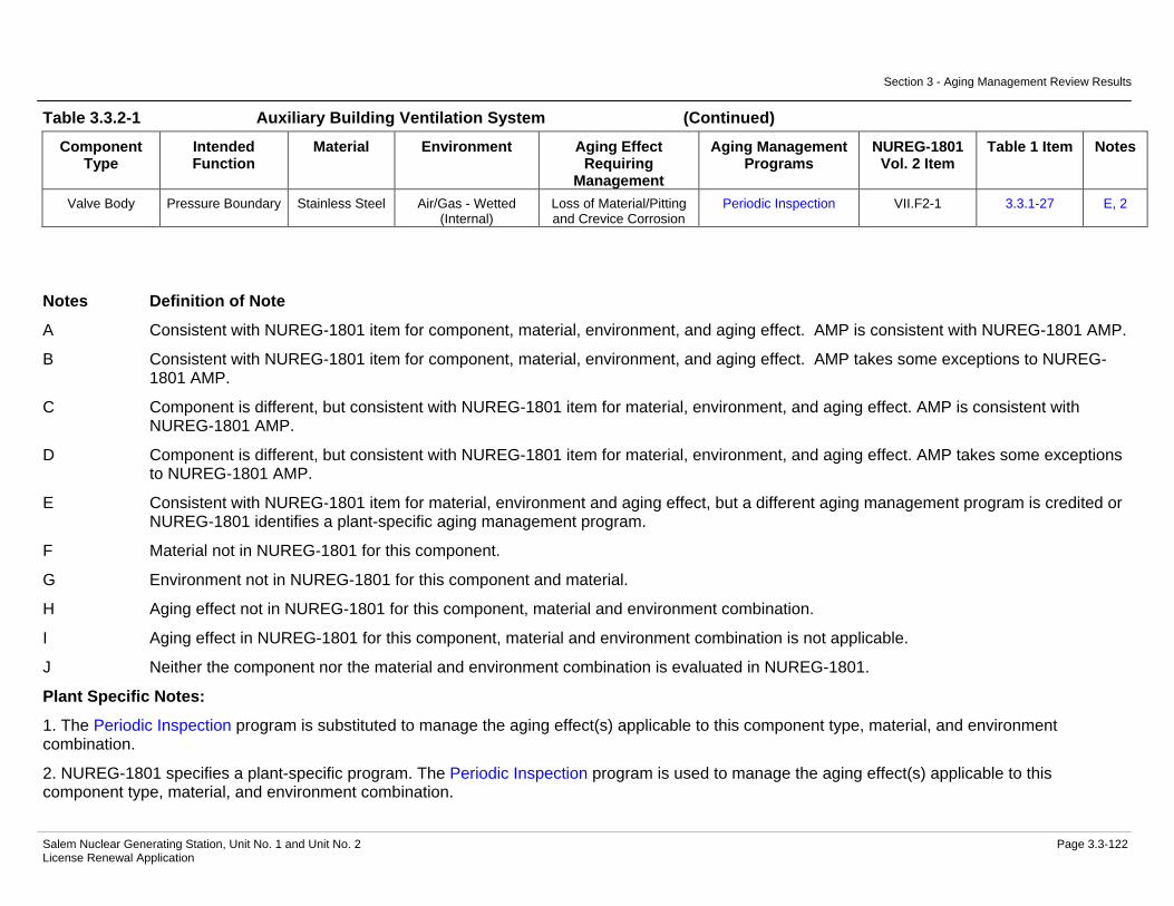
Section 3 - Aging Management Review Results
Salem Nuclear Generating Station, Unit No. 1 and Unit No. 2 Page 3.3-122 License Renewal Application
Table 3.3.2-1 Auxiliary Building Ventilation System (Continued)
Component Type
Intended Function
Material Environment Aging Effect Requiring
Management
Aging Management Programs
NUREG-1801 Vol. 2 Item
Table 1 Item Notes
Valve Body Pressure Boundary Stainless Steel Air/Gas - Wetted (Internal)
Loss of Material/Pitting and Crevice Corrosion
Periodic Inspection VII.F2-1 3.3.1-27 E, 2
Notes Definition of Note
A Consistent with NUREG-1801 item for component, material, environment, and aging effect. AMP is consistent with NUREG-1801 AMP.
B Consistent with NUREG-1801 item for component, material, environment, and aging effect. AMP takes some exceptions to NUREG-1801 AMP.
C Component is different, but consistent with NUREG-1801 item for material, environment, and aging effect. AMP is consistent with NUREG-1801 AMP.
D Component is different, but consistent with NUREG-1801 item for material, environment, and aging effect. AMP takes some exceptions to NUREG-1801 AMP.
E Consistent with NUREG-1801 item for material, environment and aging effect, but a different aging management program is credited or NUREG-1801 identifies a plant-specific aging management program.
F Material not in NUREG-1801 for this component.
G Environment not in NUREG-1801 for this component and material.
H Aging effect not in NUREG-1801 for this component, material and environment combination.
I Aging effect in NUREG-1801 for this component, material and environment combination is not applicable.
J Neither the component nor the material and environment combination is evaluated in NUREG-1801.
Plant Specific Notes:
1. The Periodic Inspection program is substituted to manage the aging effect(s) applicable to this component type, material, and environment combination.
2. NUREG-1801 specifies a plant-specific program. The Periodic Inspection program is used to manage the aging effect(s) applicable to this component type, material, and environment combination.
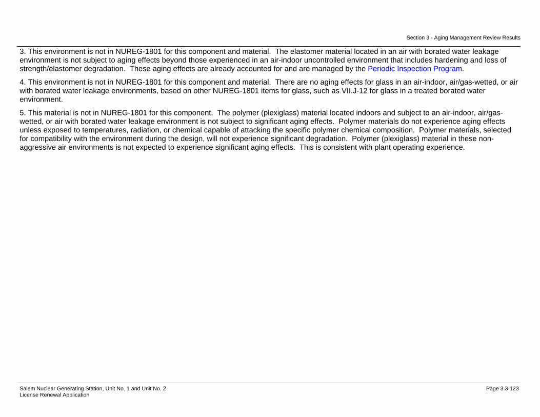
Section 3 - Aging Management Review Results
Salem Nuclear Generating Station, Unit No. 1 and Unit No. 2 Page 3.3-123 License Renewal Application
3. This environment is not in NUREG-1801 for this component and material. The elastomer material located in an air with borated water leakage environment is not subject to aging effects beyond those experienced in an air-indoor uncontrolled environment that includes hardening and loss of strength/elastomer degradation. These aging effects are already accounted for and are managed by the Periodic Inspection Program.
4. This environment is not in NUREG-1801 for this component and material. There are no aging effects for glass in an air-indoor, air/gas-wetted, or air with borated water leakage environments, based on other NUREG-1801 items for glass, such as VII.J-12 for glass in a treated borated water environment.
5. This material is not in NUREG-1801 for this component. The polymer (plexiglass) material located indoors and subject to an air-indoor, air/gas-wetted, or air with borated water leakage environment is not subject to significant aging effects. Polymer materials do not experience aging effects unless exposed to temperatures, radiation, or chemical capable of attacking the specific polymer chemical composition. Polymer materials, selected for compatibility with the environment during the design, will not experience significant degradation. Polymer (plexiglass) material in these non-aggressive air environments is not expected to experience significant aging effects. This is consistent with plant operating experience.

Section 3 - Aging Management Review Results
Salem Nuclear Generating Station, Unit No. 1 and Unit No. 2 Page 3.3-124 License Renewal Application
Table 3.3.2-2 Chemical & Volume Control System
Summary of Aging Management Evaluation
Table 3.3.2-2 Chemical & Volume Control System
Component Type
Intended Function
Material Environment Aging Effect Requiring
Management
Aging Management Programs
NUREG-1801 Vol. 2 Item
Table 1 Item Notes
Bolting Mechanical Closure Carbon and Low Alloy Steel
Bolting
Air - Indoor (External) Cumulative Fatigue Damage/Fatigue
TLAA IV.C2-10 3.1.1-7 A, 1
Bolting Mechanical Closure Carbon and Low Alloy Steel
Bolting
Air - Indoor (External) Loss of Material/General, Pitting and Crevice
Corrosion
Bolting Integrity V.E-4 3.2.1-23 B
Bolting Mechanical Closure Carbon and Low Alloy Steel
Bolting
Air - Indoor (External) Loss of Preload/Thermal Effects, Gasket Creep,
and Self-Loosening
Bolting Integrity V.E-5 3.2.1-24 B
Bolting Mechanical Closure Carbon and Low Alloy Steel
Bolting
Air with Borated Water Leakage (External)
Loss of Material/Boric Acid Corrosion
Boric Acid Corrosion VII.I-2 3.3.1-89 A
Bolting (Class 1) Mechanical Closure Carbon and Low Alloy Steel
Bolting
Air - Indoor (External) Cumulative Fatigue Damage/Fatigue
TLAA IV.C2-10 3.1.1-7 A, 1
Bolting (Class 1) Mechanical Closure Carbon and Low Alloy Steel
Bolting
Air - Indoor (External) Loss of Material/General, Pitting and Crevice
Corrosion
Bolting Integrity V.E-4 3.2.1-23 B
Bolting (Class 1) Mechanical Closure Carbon and Low Alloy Steel
Bolting
Air - Indoor (External) Loss of Preload/Thermal Effects, Gasket Creep,
and Self-Loosening
Bolting Integrity IV.C2-8 3.1.1-52 B
Bolting (Class 1) Mechanical Closure Carbon and Low Alloy Steel
Bolting
Air with Borated Water Leakage (External)
Loss of Material/Boric Acid Corrosion
Boric Acid Corrosion V.E-2 3.2.1-45 A
Class 1 Piping, Fittings and Branch
Connections < NPS 4"
Pressure Boundary Stainless Steel Air - Indoor (External) None None V.F-12 3.2.1-53 A

Section 3 - Aging Management Review Results
Salem Nuclear Generating Station, Unit No. 1 and Unit No. 2 Page 3.3-125 License Renewal Application
Table 3.3.2-2 Chemical & Volume Control System (Continued)
Component Type
Intended Function
Material Environment Aging Effect Requiring
Management
Aging Management Programs
NUREG-1801 Vol. 2 Item
Table 1 Item Notes
Class 1 Piping, Fittings and Branch
Connections < NPS 4"
Pressure Boundary Stainless Steel Air with Borated Water Leakage (External)
None None V.F-13 3.2.1-57 A
Class 1 Piping, Fittings and Branch
Connections < NPS 4"
Pressure Boundary Stainless Steel Treated Borated Water (Internal) > 140 F
Cracking/Stress Corrosion Cracking, Thermal and
Mechanical Loading
ASME Section XI Inservice Inspection,
Subsections IWB, IWC, and IWD
IV.C2-1 3.1.1-70 A
Class 1 Piping, Fittings and Branch
Connections < NPS 4"
Pressure Boundary Stainless Steel Treated Borated Water (Internal) > 140 F
Cracking/Stress Corrosion Cracking, Thermal and
Mechanical Loading
One-Time Inspection of ASME Code Class 1 Small
Bore-Piping
IV.C2-1 3.1.1-70 B
Class 1 Piping, Fittings and Branch
Connections < NPS 4"
Pressure Boundary Stainless Steel Treated Borated Water (Internal) > 140 F
Cracking/Stress Corrosion Cracking, Thermal and
Mechanical Loading
Water Chemistry IV.C2-1 3.1.1-70 A
Class 1 Piping, Fittings and Branch
Connections < NPS 4"
Pressure Boundary Stainless Steel Treated Borated Water (Internal) > 140 F
Cumulative Fatigue Damage/Fatigue
TLAA IV.C2-25 3.1.1-8 A, 1
Class 1 Piping, Fittings and Branch
Connections < NPS 4"
Pressure Boundary Stainless Steel Treated Borated Water (Internal) > 140 F
Loss of Material/Pitting and Crevice Corrosion
Water Chemistry IV.C2-15 3.1.1-83 A
Electric Heaters (Housing)
Leakage Boundary Stainless Steel Air - Indoor (External) None None V.F-12 3.2.1-53 C
Electric Heaters (Housing)
Leakage Boundary Stainless Steel Air with Borated Water Leakage (External)
None None V.F-13 3.2.1-57 C
Electric Heaters (Housing)
Leakage Boundary Stainless Steel Treated Borated Water (Internal) > 140 F
Cracking/Stress Corrosion Cracking
Water Chemistry V.D1-31 3.2.1-48 A
Electric Heaters (Housing)
Leakage Boundary Stainless Steel Treated Borated Water (Internal) > 140 F
Loss of Material/Pitting and Crevice Corrosion
Water Chemistry V.D1-30 3.2.1-49 A
Electric Heaters (Housing)
Pressure Boundary Stainless Steel Air - Indoor (External) None None V.F-12 3.2.1-53 A

Section 3 - Aging Management Review Results
Salem Nuclear Generating Station, Unit No. 1 and Unit No. 2 Page 3.3-126 License Renewal Application
Table 3.3.2-2 Chemical & Volume Control System (Continued)
Component Type
Intended Function
Material Environment Aging Effect Requiring
Management
Aging Management Programs
NUREG-1801 Vol. 2 Item
Table 1 Item Notes
Electric Heaters (Housing)
Pressure Boundary Stainless Steel Air with Borated Water Leakage (External)
None None V.F-13 3.2.1-57 C
Electric Heaters (Housing)
Pressure Boundary Stainless Steel Treated Borated Water (Internal) > 140 F
Cracking/Stress Corrosion Cracking
Water Chemistry V.D1-31 3.2.1-48 A
Electric Heaters (Housing)
Pressure Boundary Stainless Steel Treated Borated Water (Internal) > 140 F
Loss of Material/Pitting and Crevice Corrosion
Water Chemistry V.D1-30 3.2.1-49 A
Filter Housing Leakage Boundary Stainless Steel Air - Indoor (External) None None V.F-12 3.2.1-53 A Filter Housing Leakage Boundary Stainless Steel Air with Borated Water
Leakage (External) None None V.F-13 3.2.1-57 A
Filter Housing Leakage Boundary Stainless Steel Treated Borated Water (Internal)
Loss of Material/Pitting and Crevice Corrosion
Water Chemistry V.D1-30 3.2.1-49 A
Filter Housing Pressure Boundary Stainless Steel Air - Indoor (External) None None V.F-12 3.2.1-53 A Filter Housing Pressure Boundary Stainless Steel Air with Borated Water
Leakage (External) None None V.F-13 3.2.1-57 A
Filter Housing Pressure Boundary Stainless Steel Treated Borated Water (Internal)
Loss of Material/Pitting and Crevice Corrosion
Water Chemistry V.D1-30 3.2.1-49 A
Flow Device Leakage Boundary Stainless Steel Air - Indoor (External) None None V.F-12 3.2.1-53 A Flow Device Leakage Boundary Stainless Steel Air with Borated Water
Leakage (External) None None V.F-13 3.2.1-57 A
Flow Device Leakage Boundary Stainless Steel Treated Borated Water (Internal)
Loss of Material/Pitting and Crevice Corrosion
Water Chemistry V.D1-30 3.2.1-49 A
Flow Device Pressure Boundary Stainless Steel Air - Indoor (External) None None V.F-12 3.2.1-53 A Flow Device Pressure Boundary Stainless Steel Air with Borated Water
Leakage (External) None None V.F-13 3.2.1-57 A
Flow Device Pressure Boundary Stainless Steel Treated Borated Water (Internal)
Loss of Material/Pitting and Crevice Corrosion
Water Chemistry V.D1-30 3.2.1-49 A
Flow Element Leakage Boundary Stainless Steel Air - Indoor (External) None None V.F-12 3.2.1-53 A Flow Element Leakage Boundary Stainless Steel Air with Borated Water
Leakage (External) None None V.F-13 3.2.1-57 A
Flow Element Leakage Boundary Stainless Steel Treated Borated Water (Internal)
Loss of Material/Pitting and Crevice Corrosion
Water Chemistry V.D1-30 3.2.1-49 A
Flow Element Pressure Boundary Stainless Steel Air - Indoor (External) None None V.F-12 3.2.1-53 A

Section 3 - Aging Management Review Results
Salem Nuclear Generating Station, Unit No. 1 and Unit No. 2 Page 3.3-127 License Renewal Application
Table 3.3.2-2 Chemical & Volume Control System (Continued)
Component Type
Intended Function
Material Environment Aging Effect Requiring
Management
Aging Management Programs
NUREG-1801 Vol. 2 Item
Table 1 Item Notes
Flow Element Pressure Boundary Stainless Steel Air with Borated Water Leakage (External)
None None V.F-13 3.2.1-57 A
Flow Element Pressure Boundary Stainless Steel Treated Borated Water (Internal)
Loss of Material/Pitting and Crevice Corrosion
Water Chemistry V.D1-30 3.2.1-49 A
Heat Exchanger Components
(Charging Pump Gear Oil Cooler)
Evaluated with the Service Water
System
Not Applicable Not Applicable Not Applicable Not Applicable 2
Heat Exchanger Components
(Charging Pump Lube Oil Cooler)
Evaluated with the Service Water
System
Not Applicable Not Applicable Not Applicable Not Applicable 2
Heat Exchanger Components
(Charging Pump Mechanical Seal)
Evaluated with the Component Cooling
System
Not Applicable Not Applicable Not Applicable Not Applicable 3
Heat Exchanger Components
(Excess Letdown)
Evaluated with the Component Cooling
System
Not Applicable Not Applicable Not Applicable Not Applicable 3
Heat Exchanger Components
(Letdown)
Evaluated with the Component Cooling
System
Not Applicable Not Applicable Not Applicable Not Applicable 3
Heat Exchanger Components
(Positive Displacement
Pump Gyrol/Lube Oil)
Evaluated with the Component Cooling
System
Not Applicable Not Applicable Not Applicable Not Applicable 3
Heat Exchanger Components
(Primary Water Storage Tank)
Leakage Boundary Stainless Steel (Shellside
Components)
Air - Indoor (External) None None V.F-12 3.2.1-53 C
Heat Exchanger Components
(Primary Water Storage Tank)
Leakage Boundary Stainless Steel (Shellside
Components)
Air with Borated Water Leakage (External)
None None V.F-13 3.2.1-57 C
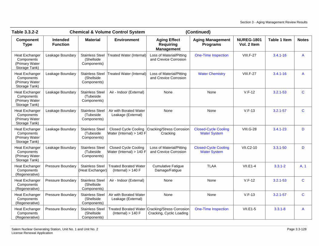
Section 3 - Aging Management Review Results
Salem Nuclear Generating Station, Unit No. 1 and Unit No. 2 Page 3.3-128 License Renewal Application
Table 3.3.2-2 Chemical & Volume Control System (Continued)
Component Type
Intended Function
Material Environment Aging Effect Requiring
Management
Aging Management Programs
NUREG-1801 Vol. 2 Item
Table 1 Item Notes
Heat Exchanger Components
(Primary Water Storage Tank)
Leakage Boundary Stainless Steel (Shellside
Components)
Treated Water (Internal) Loss of Material/Pitting and Crevice Corrosion
One-Time Inspection VIII.F-27 3.4.1-16 A
Heat Exchanger Components
(Primary Water Storage Tank)
Leakage Boundary Stainless Steel (Shellside
Components)
Treated Water (Internal) Loss of Material/Pitting and Crevice Corrosion
Water Chemistry VIII.F-27 3.4.1-16 A
Heat Exchanger Components
(Primary Water Storage Tank)
Leakage Boundary Stainless Steel (Tubeside
Components)
Air - Indoor (External) None None V.F-12 3.2.1-53 C
Heat Exchanger Components
(Primary Water Storage Tank)
Leakage Boundary Stainless Steel (Tubeside
Components)
Air with Borated Water Leakage (External)
None None V.F-13 3.2.1-57 C
Heat Exchanger Components
(Primary Water Storage Tank)
Leakage Boundary Stainless Steel (Tubeside
Components)
Closed Cycle Cooling Water (Internal) > 140 F
Cracking/Stress Corrosion Cracking
Closed-Cycle Cooling Water System
VIII.G-28 3.4.1-23 D
Heat Exchanger Components
(Primary Water Storage Tank)
Leakage Boundary Stainless Steel (Tubeside
Components)
Closed Cycle Cooling Water (Internal) > 140 F
Loss of Material/Pitting and Crevice Corrosion
Closed-Cycle Cooling Water System
VII.C2-10 3.3.1-50 D
Heat Exchanger Components
(Regenerative)
Pressure Boundary Stainless Steel (Heat Exchanger)
Treated Borated Water (Internal) > 140 F
Cumulative Fatigue Damage/Fatigue
TLAA VII.E1-4 3.3.1-2 A, 1
Heat Exchanger Components
(Regenerative)
Pressure Boundary Stainless Steel (Shellside
Components)
Air - Indoor (External) None None V.F-12 3.2.1-53 C
Heat Exchanger Components
(Regenerative)
Pressure Boundary Stainless Steel (Shellside
Components)
Air with Borated Water Leakage (External)
None None V.F-13 3.2.1-57 C
Heat Exchanger Components
(Regenerative)
Pressure Boundary Stainless Steel (Shellside
Components)
Treated Borated Water (Internal) > 140 F
Cracking/Stress Corrosion Cracking, Cyclic Loading
One-Time Inspection VII.E1-5 3.3.1-8 A
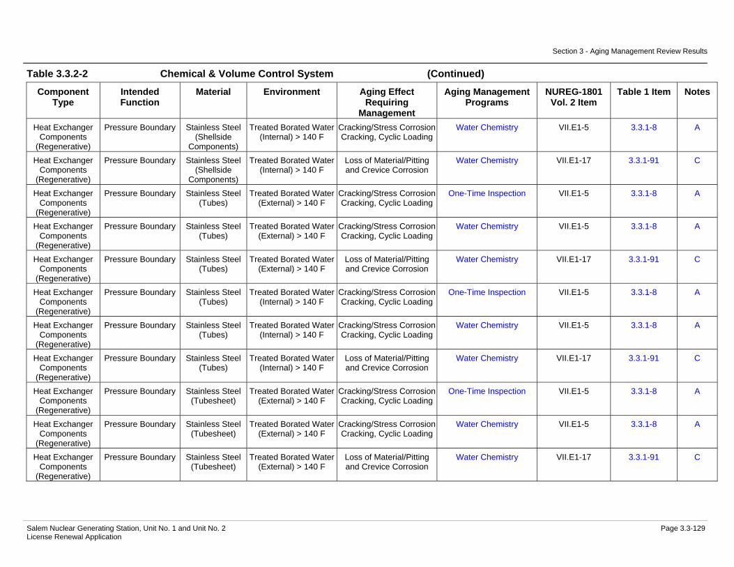
Section 3 - Aging Management Review Results
Salem Nuclear Generating Station, Unit No. 1 and Unit No. 2 Page 3.3-129 License Renewal Application
Table 3.3.2-2 Chemical & Volume Control System (Continued)
Component Type
Intended Function
Material Environment Aging Effect Requiring
Management
Aging Management Programs
NUREG-1801 Vol. 2 Item
Table 1 Item Notes
Heat Exchanger Components
(Regenerative)
Pressure Boundary Stainless Steel (Shellside
Components)
Treated Borated Water (Internal) > 140 F
Cracking/Stress Corrosion Cracking, Cyclic Loading
Water Chemistry VII.E1-5 3.3.1-8 A
Heat Exchanger Components
(Regenerative)
Pressure Boundary Stainless Steel (Shellside
Components)
Treated Borated Water (Internal) > 140 F
Loss of Material/Pitting and Crevice Corrosion
Water Chemistry VII.E1-17 3.3.1-91 C
Heat Exchanger Components
(Regenerative)
Pressure Boundary Stainless Steel (Tubes)
Treated Borated Water (External) > 140 F
Cracking/Stress Corrosion Cracking, Cyclic Loading
One-Time Inspection VII.E1-5 3.3.1-8 A
Heat Exchanger Components
(Regenerative)
Pressure Boundary Stainless Steel (Tubes)
Treated Borated Water (External) > 140 F
Cracking/Stress Corrosion Cracking, Cyclic Loading
Water Chemistry VII.E1-5 3.3.1-8 A
Heat Exchanger Components
(Regenerative)
Pressure Boundary Stainless Steel (Tubes)
Treated Borated Water (External) > 140 F
Loss of Material/Pitting and Crevice Corrosion
Water Chemistry VII.E1-17 3.3.1-91 C
Heat Exchanger Components
(Regenerative)
Pressure Boundary Stainless Steel (Tubes)
Treated Borated Water (Internal) > 140 F
Cracking/Stress Corrosion Cracking, Cyclic Loading
One-Time Inspection VII.E1-5 3.3.1-8 A
Heat Exchanger Components
(Regenerative)
Pressure Boundary Stainless Steel (Tubes)
Treated Borated Water (Internal) > 140 F
Cracking/Stress Corrosion Cracking, Cyclic Loading
Water Chemistry VII.E1-5 3.3.1-8 A
Heat Exchanger Components
(Regenerative)
Pressure Boundary Stainless Steel (Tubes)
Treated Borated Water (Internal) > 140 F
Loss of Material/Pitting and Crevice Corrosion
Water Chemistry VII.E1-17 3.3.1-91 C
Heat Exchanger Components
(Regenerative)
Pressure Boundary Stainless Steel (Tubesheet)
Treated Borated Water (External) > 140 F
Cracking/Stress Corrosion Cracking, Cyclic Loading
One-Time Inspection VII.E1-5 3.3.1-8 A
Heat Exchanger Components
(Regenerative)
Pressure Boundary Stainless Steel (Tubesheet)
Treated Borated Water (External) > 140 F
Cracking/Stress Corrosion Cracking, Cyclic Loading
Water Chemistry VII.E1-5 3.3.1-8 A
Heat Exchanger Components
(Regenerative)
Pressure Boundary Stainless Steel (Tubesheet)
Treated Borated Water (External) > 140 F
Loss of Material/Pitting and Crevice Corrosion
Water Chemistry VII.E1-17 3.3.1-91 C
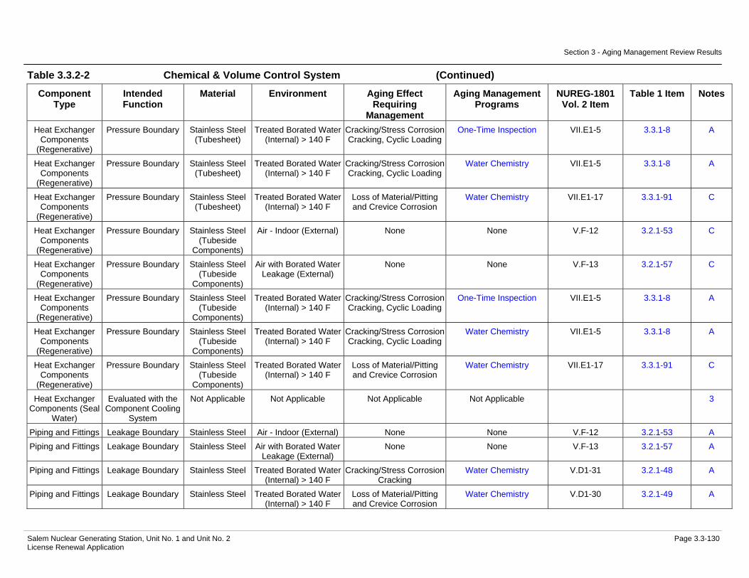
Section 3 - Aging Management Review Results
Salem Nuclear Generating Station, Unit No. 1 and Unit No. 2 Page 3.3-130 License Renewal Application
Table 3.3.2-2 Chemical & Volume Control System (Continued)
Component Type
Intended Function
Material Environment Aging Effect Requiring
Management
Aging Management Programs
NUREG-1801 Vol. 2 Item
Table 1 Item Notes
Heat Exchanger Components
(Regenerative)
Pressure Boundary Stainless Steel (Tubesheet)
Treated Borated Water (Internal) > 140 F
Cracking/Stress Corrosion Cracking, Cyclic Loading
One-Time Inspection VII.E1-5 3.3.1-8 A
Heat Exchanger Components
(Regenerative)
Pressure Boundary Stainless Steel (Tubesheet)
Treated Borated Water (Internal) > 140 F
Cracking/Stress Corrosion Cracking, Cyclic Loading
Water Chemistry VII.E1-5 3.3.1-8 A
Heat Exchanger Components
(Regenerative)
Pressure Boundary Stainless Steel (Tubesheet)
Treated Borated Water (Internal) > 140 F
Loss of Material/Pitting and Crevice Corrosion
Water Chemistry VII.E1-17 3.3.1-91 C
Heat Exchanger Components
(Regenerative)
Pressure Boundary Stainless Steel (Tubeside
Components)
Air - Indoor (External) None None V.F-12 3.2.1-53 C
Heat Exchanger Components
(Regenerative)
Pressure Boundary Stainless Steel (Tubeside
Components)
Air with Borated Water Leakage (External)
None None V.F-13 3.2.1-57 C
Heat Exchanger Components
(Regenerative)
Pressure Boundary Stainless Steel (Tubeside
Components)
Treated Borated Water (Internal) > 140 F
Cracking/Stress Corrosion Cracking, Cyclic Loading
One-Time Inspection VII.E1-5 3.3.1-8 A
Heat Exchanger Components
(Regenerative)
Pressure Boundary Stainless Steel (Tubeside
Components)
Treated Borated Water (Internal) > 140 F
Cracking/Stress Corrosion Cracking, Cyclic Loading
Water Chemistry VII.E1-5 3.3.1-8 A
Heat Exchanger Components
(Regenerative)
Pressure Boundary Stainless Steel (Tubeside
Components)
Treated Borated Water (Internal) > 140 F
Loss of Material/Pitting and Crevice Corrosion
Water Chemistry VII.E1-17 3.3.1-91 C
Heat Exchanger Components (Seal
Water)
Evaluated with the Component Cooling
System
Not Applicable Not Applicable Not Applicable Not Applicable 3
Piping and Fittings Leakage Boundary Stainless Steel Air - Indoor (External) None None V.F-12 3.2.1-53 A Piping and Fittings Leakage Boundary Stainless Steel Air with Borated Water
Leakage (External) None None V.F-13 3.2.1-57 A
Piping and Fittings Leakage Boundary Stainless Steel Treated Borated Water (Internal) > 140 F
Cracking/Stress Corrosion Cracking
Water Chemistry V.D1-31 3.2.1-48 A
Piping and Fittings Leakage Boundary Stainless Steel Treated Borated Water (Internal) > 140 F
Loss of Material/Pitting and Crevice Corrosion
Water Chemistry V.D1-30 3.2.1-49 A

Section 3 - Aging Management Review Results
Salem Nuclear Generating Station, Unit No. 1 and Unit No. 2 Page 3.3-131 License Renewal Application
Table 3.3.2-2 Chemical & Volume Control System (Continued)
Component Type
Intended Function
Material Environment Aging Effect Requiring
Management
Aging Management Programs
NUREG-1801 Vol. 2 Item
Table 1 Item Notes
Piping and Fittings Leakage Boundary Stainless Steel Treated Water (Internal) Loss of Material/Pitting and Crevice Corrosion
One-Time Inspection VII.E3-15 3.3.1-24 A
Piping and Fittings Leakage Boundary Stainless Steel Treated Water (Internal) Loss of Material/Pitting and Crevice Corrosion
Water Chemistry VII.E3-15 3.3.1-24 A
Piping and Fittings Pressure Boundary Stainless Steel Air - Indoor (External) None None V.F-12 3.2.1-53 A Piping and Fittings Pressure Boundary Stainless Steel Air with Borated Water
Leakage (External) None None V.F-13 3.2.1-57 A
Piping and Fittings Pressure Boundary Stainless Steel Air with Steam or Water Leakage (External)
Loss of Material/Pitting and Crevice Corrosion
Periodic Inspection VII.F3-1 3.3.1-27 E, 4
Piping and Fittings Pressure Boundary Stainless Steel Treated Borated Water (Internal) > 140 F
Cracking/Stress Corrosion Cracking
Water Chemistry V.D1-31 3.2.1-48 A
Piping and Fittings Pressure Boundary Stainless Steel Treated Borated Water (Internal) > 140 F
Cumulative Fatigue Damage/Fatigue
TLAA VII.E1-16 3.3.1-2 A, 1
Piping and Fittings Pressure Boundary Stainless Steel Treated Borated Water (Internal) > 140 F
Loss of Material/Pitting and Crevice Corrosion
Water Chemistry V.D1-30 3.2.1-49 A
Piping and Fittings Pressure Boundary Stainless Steel Treated Water (Internal) Loss of Material/Pitting and Crevice Corrosion
One-Time Inspection VII.E3-15 3.3.1-24 A
Piping and Fittings Pressure Boundary Stainless Steel Treated Water (Internal) Loss of Material/Pitting and Crevice Corrosion
Water Chemistry VII.E3-15 3.3.1-24 A
Pump Casing (11,12 Charging
Pump)
Pressure Boundary Stainless Steel Air - Indoor (External) None None V.F-12 3.2.1-53 A
Pump Casing (11,12 Charging
Pump)
Pressure Boundary Stainless Steel Air with Borated Water Leakage (External)
None None V.F-13 3.2.1-57 A
Pump Casing (11,12 Charging
Pump)
Pressure Boundary Stainless Steel Treated Borated Water (Internal)
Cracking/Stress Corrosion Cracking, Cyclic Loading
One-Time Inspection VII.E1-7 3.3.1-9 A
Pump Casing (11,12 Charging
Pump)
Pressure Boundary Stainless Steel Treated Borated Water (Internal)
Cracking/Stress Corrosion Cracking, Cyclic Loading
Water Chemistry VII.E1-7 3.3.1-9 A
Pump Casing (11,12 Charging
Pump)
Pressure Boundary Stainless Steel Treated Borated Water (Internal)
Loss of Material/Pitting and Crevice Corrosion
Water Chemistry VII.E1-17 3.3.1-91 A
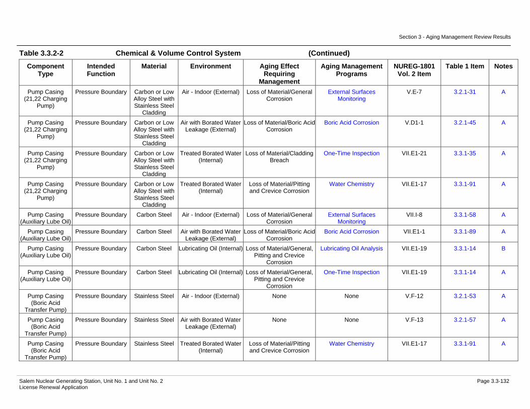
Section 3 - Aging Management Review Results
Salem Nuclear Generating Station, Unit No. 1 and Unit No. 2 Page 3.3-132 License Renewal Application
Table 3.3.2-2 Chemical & Volume Control System (Continued)
Component Type
Intended Function
Material Environment Aging Effect Requiring
Management
Aging Management Programs
NUREG-1801 Vol. 2 Item
Table 1 Item Notes
Pump Casing (21,22 Charging
Pump)
Pressure Boundary Carbon or Low Alloy Steel with Stainless Steel
Cladding
Air - Indoor (External) Loss of Material/General Corrosion
External Surfaces Monitoring
V.E-7 3.2.1-31 A
Pump Casing (21,22 Charging
Pump)
Pressure Boundary Carbon or Low Alloy Steel with Stainless Steel
Cladding
Air with Borated Water Leakage (External)
Loss of Material/Boric Acid Corrosion
Boric Acid Corrosion V.D1-1 3.2.1-45 A
Pump Casing (21,22 Charging
Pump)
Pressure Boundary Carbon or Low Alloy Steel with Stainless Steel
Cladding
Treated Borated Water (Internal)
Loss of Material/Cladding Breach
One-Time Inspection VII.E1-21 3.3.1-35 A
Pump Casing (21,22 Charging
Pump)
Pressure Boundary Carbon or Low Alloy Steel with Stainless Steel
Cladding
Treated Borated Water (Internal)
Loss of Material/Pitting and Crevice Corrosion
Water Chemistry VII.E1-17 3.3.1-91 A
Pump Casing (Auxiliary Lube Oil)
Pressure Boundary Carbon Steel Air - Indoor (External) Loss of Material/General Corrosion
External Surfaces Monitoring
VII.I-8 3.3.1-58 A
Pump Casing (Auxiliary Lube Oil)
Pressure Boundary Carbon Steel Air with Borated Water Leakage (External)
Loss of Material/Boric Acid Corrosion
Boric Acid Corrosion VII.E1-1 3.3.1-89 A
Pump Casing (Auxiliary Lube Oil)
Pressure Boundary Carbon Steel Lubricating Oil (Internal) Loss of Material/General, Pitting and Crevice
Corrosion
Lubricating Oil Analysis VII.E1-19 3.3.1-14 B
Pump Casing (Auxiliary Lube Oil)
Pressure Boundary Carbon Steel Lubricating Oil (Internal) Loss of Material/General, Pitting and Crevice
Corrosion
One-Time Inspection VII.E1-19 3.3.1-14 A
Pump Casing (Boric Acid
Transfer Pump)
Pressure Boundary Stainless Steel Air - Indoor (External) None None V.F-12 3.2.1-53 A
Pump Casing (Boric Acid
Transfer Pump)
Pressure Boundary Stainless Steel Air with Borated Water Leakage (External)
None None V.F-13 3.2.1-57 A
Pump Casing (Boric Acid
Transfer Pump)
Pressure Boundary Stainless Steel Treated Borated Water (Internal)
Loss of Material/Pitting and Crevice Corrosion
Water Chemistry VII.E1-17 3.3.1-91 A

Section 3 - Aging Management Review Results
Salem Nuclear Generating Station, Unit No. 1 and Unit No. 2 Page 3.3-133 License Renewal Application
Table 3.3.2-2 Chemical & Volume Control System (Continued)
Component Type
Intended Function
Material Environment Aging Effect Requiring
Management
Aging Management Programs
NUREG-1801 Vol. 2 Item
Table 1 Item Notes
Pump Casing (CVCS Holdup Tank Pump)
Leakage Boundary Stainless Steel Air - Indoor (External) None None V.F-12 3.2.1-53 A
Pump Casing (CVCS Holdup Tank Pump)
Leakage Boundary Stainless Steel Air with Borated Water Leakage (External)
None None V.F-13 3.2.1-57 A
Pump Casing (CVCS Holdup Tank Pump)
Leakage Boundary Stainless Steel Treated Borated Water (Internal)
Loss of Material/Pitting and Crevice Corrosion
Water Chemistry VII.E1-17 3.3.1-91 A
Pump Casing (Gas Stripper Feed
Pump)
Leakage Boundary Stainless Steel Air - Indoor (External) None None V.F-12 3.2.1-53 A
Pump Casing (Gas Stripper Feed
Pump)
Leakage Boundary Stainless Steel Air with Borated Water Leakage (External)
None None V.F-13 3.2.1-57 A
Pump Casing (Gas Stripper Feed
Pump)
Leakage Boundary Stainless Steel Treated Borated Water (Internal)
Loss of Material/Pitting and Crevice Corrosion
Water Chemistry VII.E1-17 3.3.1-91 A
Pump Casing (PWST Heating
Water Circulator)
Leakage Boundary Stainless Steel Air - Indoor (External) None None V.F-12 3.2.1-53 A
Pump Casing (PWST Heating
Water Circulator)
Leakage Boundary Stainless Steel Air with Borated Water Leakage (External)
None None V.F-13 3.2.1-57 A
Pump Casing (PWST Heating
Water Circulator)
Leakage Boundary Stainless Steel Treated Water (Internal) Loss of Material/Pitting and Crevice Corrosion
One-Time Inspection VII.E3-15 3.3.1-24 A
Pump Casing (PWST Heating
Water Circulator)
Leakage Boundary Stainless Steel Treated Water (Internal) Loss of Material/Pitting and Crevice Corrosion
Water Chemistry VII.E3-15 3.3.1-24 A
Pump Casing (Positive
Displacement 13,23 Charging
Pump)
Pressure Boundary Stainless Steel Air - Indoor (External) None None V.F-12 3.2.1-53 A

Section 3 - Aging Management Review Results
Salem Nuclear Generating Station, Unit No. 1 and Unit No. 2 Page 3.3-134 License Renewal Application
Table 3.3.2-2 Chemical & Volume Control System (Continued)
Component Type
Intended Function
Material Environment Aging Effect Requiring
Management
Aging Management Programs
NUREG-1801 Vol. 2 Item
Table 1 Item Notes
Pump Casing (Positive
Displacement 13,23 Charging
Pump)
Pressure Boundary Stainless Steel Air with Borated Water Leakage (External)
None None V.F-13 3.2.1-57 A
Pump Casing (Positive
Displacement 13,23 Charging
Pump)
Pressure Boundary Stainless Steel Treated Borated Water (Internal)
Loss of Material/Pitting and Crevice Corrosion
Water Chemistry VII.E1-17 3.3.1-91 A
Pump Casing (Primary Water
Pump)
Leakage Boundary Stainless Steel Air - Indoor (External) None None V.F-12 3.2.1-53 A
Pump Casing (Primary Water
Pump)
Leakage Boundary Stainless Steel Air with Borated Water Leakage (External)
None None V.F-13 3.2.1-57 A
Pump Casing (Primary Water
Pump)
Leakage Boundary Stainless Steel Treated Water (Internal) Loss of Material/Pitting and Crevice Corrosion
One-Time Inspection VII.E3-15 3.3.1-24 A
Pump Casing (Primary Water
Pump)
Leakage Boundary Stainless Steel Treated Water (Internal) Loss of Material/Pitting and Crevice Corrosion
Water Chemistry VII.E3-15 3.3.1-24 A
Pump Casing (Zinc Injection)
Leakage Boundary Stainless Steel Air - Indoor (External) None None V.F-12 3.2.1-53 A
Pump Casing (Zinc Injection)
Leakage Boundary Stainless Steel Air with Borated Water Leakage (External)
None None V.F-13 3.2.1-57 A
Pump Casing (Zinc Injection)
Leakage Boundary Stainless Steel Treated Water (Internal) Loss of Material/Pitting and Crevice Corrosion
One-Time Inspection VII.E3-15 3.3.1-24 A
Pump Casing (Zinc Injection)
Leakage Boundary Stainless Steel Treated Water (Internal) Loss of Material/Pitting and Crevice Corrosion
Water Chemistry VII.E3-15 3.3.1-24 A
Restricting Orifices Pressure Boundary Stainless Steel Air - Indoor (External) None None V.F-12 3.2.1-53 A Restricting Orifices Pressure Boundary Stainless Steel Air with Borated Water
Leakage (External) None None V.F-13 3.2.1-57 A

Section 3 - Aging Management Review Results
Salem Nuclear Generating Station, Unit No. 1 and Unit No. 2 Page 3.3-135 License Renewal Application
Table 3.3.2-2 Chemical & Volume Control System (Continued)
Component Type
Intended Function
Material Environment Aging Effect Requiring
Management
Aging Management Programs
NUREG-1801 Vol. 2 Item
Table 1 Item Notes
Restricting Orifices Pressure Boundary Stainless Steel Treated Borated Water (Internal) > 140 F
Cracking/Stress Corrosion Cracking
Water Chemistry V.D1-31 3.2.1-48 A
Restricting Orifices Pressure Boundary Stainless Steel Treated Borated Water (Internal) > 140 F
Loss of Material/Pitting and Crevice Corrosion
Water Chemistry V.D1-30 3.2.1-49 A
Restricting Orifices Throttle Stainless Steel Air - Indoor (External) None None V.F-12 3.2.1-53 A Restricting Orifices Throttle Stainless Steel Air with Borated Water
Leakage (External) None None V.F-13 3.2.1-57 A
Restricting Orifices Throttle Stainless Steel Treated Borated Water (Internal) > 140 F
Cracking/Stress Corrosion Cracking
Water Chemistry V.D1-31 3.2.1-48 A
Restricting Orifices Throttle Stainless Steel Treated Borated Water (Internal) > 140 F
Loss of Material/Erosion Water Chemistry V.D1-14 3.2.1-12 E, 5
Restricting Orifices Throttle Stainless Steel Treated Borated Water (Internal) > 140 F
Loss of Material/Pitting and Crevice Corrosion
Water Chemistry V.D1-30 3.2.1-49 A
Strainer Filter Stainless Steel Treated Borated Water (External)
Loss of Material/Pitting and Crevice Corrosion
Water Chemistry VII.E1-17 3.3.1-91 A
Strainer Filter Stainless Steel Treated Borated Water (Internal)
Loss of Material/Pitting and Crevice Corrosion
Water Chemistry VII.E1-17 3.3.1-91 A
Strainer Body Leakage Boundary Stainless Steel Air - Indoor (External) None None V.F-12 3.2.1-53 A Strainer Body Leakage Boundary Stainless Steel Air with Borated Water
Leakage (External) None None V.F-13 3.2.1-57 A
Strainer Body Leakage Boundary Stainless Steel Treated Water (Internal) Loss of Material/Pitting and Crevice Corrosion
One-Time Inspection VII.E3-15 3.3.1-24 A
Strainer Body Leakage Boundary Stainless Steel Treated Water (Internal) Loss of Material/Pitting and Crevice Corrosion
Water Chemistry VII.E3-15 3.3.1-24 A
Strainer Body Pressure Boundary Stainless Steel Air - Indoor (External) None None V.F-12 3.2.1-53 A Strainer Body Pressure Boundary Stainless Steel Air with Borated Water
Leakage (External) None None V.F-13 3.2.1-57 A
Strainer Body Pressure Boundary Stainless Steel Treated Borated Water (Internal)
Loss of Material/Pitting and Crevice Corrosion
Water Chemistry VII.E1-17 3.3.1-91 A
Tanks (Boric Acid Storage & Batching)
Pressure Boundary Stainless Steel Air - Indoor (External) None None V.F-12 3.2.1-53 C

Section 3 - Aging Management Review Results
Salem Nuclear Generating Station, Unit No. 1 and Unit No. 2 Page 3.3-136 License Renewal Application
Table 3.3.2-2 Chemical & Volume Control System (Continued)
Component Type
Intended Function
Material Environment Aging Effect Requiring
Management
Aging Management Programs
NUREG-1801 Vol. 2 Item
Table 1 Item Notes
Tanks (Boric Acid Storage & Batching)
Pressure Boundary Stainless Steel Air with Borated Water Leakage (External)
None None V.F-13 3.2.1-57 C
Tanks (Boric Acid Storage & Batching)
Pressure Boundary Stainless Steel Treated Borated Water (Internal)
Loss of Material/Pitting and Crevice Corrosion
Water Chemistry V.D1-30 3.2.1-49 A
Tanks (CVCS Holdup)
Leakage Boundary Stainless Steel Air - Indoor (External) None None V.F-12 3.2.1-53 C
Tanks (CVCS Holdup)
Leakage Boundary Stainless Steel Air with Borated Water Leakage (External)
None None V.F-13 3.2.1-57 C
Tanks (CVCS Holdup)
Leakage Boundary Stainless Steel Treated Borated Water (Internal)
Loss of Material/Pitting and Crevice Corrosion
Water Chemistry V.D1-30 3.2.1-49 A
Tanks (Chemical Addition)
Pressure Boundary Stainless Steel Air - Indoor (External) None None V.F-12 3.2.1-53 C
Tanks (Chemical Addition)
Pressure Boundary Stainless Steel Air with Borated Water Leakage (External)
None None V.F-13 3.2.1-57 C
Tanks (Chemical Addition)
Pressure Boundary Stainless Steel Treated Water (Internal) Loss of Material/Pitting and Crevice Corrosion
One-Time Inspection VII.E3-15 3.3.1-24 C
Tanks (Chemical Addition)
Pressure Boundary Stainless Steel Treated Water (Internal) Loss of Material/Pitting and Crevice Corrosion
Water Chemistry VII.E3-15 3.3.1-24 C
Tanks (Demineralizers)
Leakage Boundary Stainless Steel Air - Indoor (External) None None V.F-12 3.2.1-53 C
Tanks (Demineralizers)
Leakage Boundary Stainless Steel Air with Borated Water Leakage (External)
None None V.F-13 3.2.1-57 C
Tanks (Demineralizers)
Leakage Boundary Stainless Steel Treated Borated Water (Internal)
Loss of Material/Pitting and Crevice Corrosion
Water Chemistry V.D1-30 3.2.1-49 A
Tanks (Primary Water Storage)
Leakage Boundary Stainless Steel Air - Outdoor (External) Loss of Material/Pitting and Crevice Corrosion
Aboveground Non-Steel Tanks
III.B2-7 3.5.1-50 E, 6
Tanks (Primary Water Storage)
Leakage Boundary Stainless Steel Soil (External) Loss of Material/Pitting, Crevice, and
Microbiologically Influenced Corrosion
Aboveground Non-Steel Tanks
G, 7
Tanks (Primary Water Storage)
Leakage Boundary Stainless Steel Treated Water (Internal) Loss of Material/Pitting and Crevice Corrosion
One-Time Inspection VII.E3-15 3.3.1-24 C
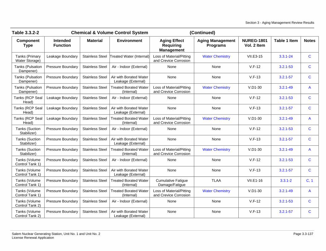
Section 3 - Aging Management Review Results
Salem Nuclear Generating Station, Unit No. 1 and Unit No. 2 Page 3.3-137 License Renewal Application
Table 3.3.2-2 Chemical & Volume Control System (Continued)
Component Type
Intended Function
Material Environment Aging Effect Requiring
Management
Aging Management Programs
NUREG-1801 Vol. 2 Item
Table 1 Item Notes
Tanks (Primary Water Storage)
Leakage Boundary Stainless Steel Treated Water (Internal) Loss of Material/Pitting and Crevice Corrosion
Water Chemistry VII.E3-15 3.3.1-24 C
Tanks (Pulsation Dampener)
Pressure Boundary Stainless Steel Air - Indoor (External) None None V.F-12 3.2.1-53 C
Tanks (Pulsation Dampener)
Pressure Boundary Stainless Steel Air with Borated Water Leakage (External)
None None V.F-13 3.2.1-57 C
Tanks (Pulsation Dampener)
Pressure Boundary Stainless Steel Treated Borated Water (Internal)
Loss of Material/Pitting and Crevice Corrosion
Water Chemistry V.D1-30 3.2.1-49 A
Tanks (RCP Seal Head)
Leakage Boundary Stainless Steel Air - Indoor (External) None None V.F-12 3.2.1-53 C
Tanks (RCP Seal Head)
Leakage Boundary Stainless Steel Air with Borated Water Leakage (External)
None None V.F-13 3.2.1-57 C
Tanks (RCP Seal Head)
Leakage Boundary Stainless Steel Treated Borated Water (Internal)
Loss of Material/Pitting and Crevice Corrosion
Water Chemistry V.D1-30 3.2.1-49 A
Tanks (Suction Stabilizer)
Pressure Boundary Stainless Steel Air - Indoor (External) None None V.F-12 3.2.1-53 C
Tanks (Suction Stabilizer)
Pressure Boundary Stainless Steel Air with Borated Water Leakage (External)
None None V.F-13 3.2.1-57 C
Tanks (Suction Stabilizer)
Pressure Boundary Stainless Steel Treated Borated Water (Internal)
Loss of Material/Pitting and Crevice Corrosion
Water Chemistry V.D1-30 3.2.1-49 A
Tanks (Volume Control Tank 1)
Pressure Boundary Stainless Steel Air - Indoor (External) None None V.F-12 3.2.1-53 C
Tanks (Volume Control Tank 1)
Pressure Boundary Stainless Steel Air with Borated Water Leakage (External)
None None V.F-13 3.2.1-57 C
Tanks (Volume Control Tank 1)
Pressure Boundary Stainless Steel Treated Borated Water (Internal)
Cumulative Fatigue Damage/Fatigue
TLAA VII.E1-16 3.3.1-2 C, 1
Tanks (Volume Control Tank 1)
Pressure Boundary Stainless Steel Treated Borated Water (Internal)
Loss of Material/Pitting and Crevice Corrosion
Water Chemistry V.D1-30 3.2.1-49 A
Tanks (Volume Control Tank 2)
Pressure Boundary Stainless Steel Air - Indoor (External) None None V.F-12 3.2.1-53 C
Tanks (Volume Control Tank 2)
Pressure Boundary Stainless Steel Air with Borated Water Leakage (External)
None None V.F-13 3.2.1-57 C

Section 3 - Aging Management Review Results
Salem Nuclear Generating Station, Unit No. 1 and Unit No. 2 Page 3.3-138 License Renewal Application
Table 3.3.2-2 Chemical & Volume Control System (Continued)
Component Type
Intended Function
Material Environment Aging Effect Requiring
Management
Aging Management Programs
NUREG-1801 Vol. 2 Item
Table 1 Item Notes
Tanks (Volume Control Tank 2)
Pressure Boundary Stainless Steel Treated Borated Water (Internal)
Loss of Material/Pitting and Crevice Corrosion
Water Chemistry V.D1-30 3.2.1-49 A
Thermowell Leakage Boundary Stainless Steel Air - Indoor (External) None None V.F-12 3.2.1-53 A Thermowell Leakage Boundary Stainless Steel Air with Borated Water
Leakage (External) None None V.F-13 3.2.1-57 A
Thermowell Leakage Boundary Stainless Steel Treated Borated Water (Internal)
Loss of Material/Pitting and Crevice Corrosion
Water Chemistry V.D1-30 3.2.1-49 A
Thermowell Pressure Boundary Stainless Steel Air - Indoor (External) None None V.F-12 3.2.1-53 A Thermowell Pressure Boundary Stainless Steel Air with Borated Water
Leakage (External) None None V.F-13 3.2.1-57 A
Thermowell Pressure Boundary Stainless Steel Treated Borated Water (Internal)
Loss of Material/Pitting and Crevice Corrosion
Water Chemistry V.D1-30 3.2.1-49 A
Valve Body Leakage Boundary Cast Austenitic Stainless Steel
(CASS)
Air - Indoor (External) None None V.F-12 3.2.1-53 A
Valve Body Leakage Boundary Cast Austenitic Stainless Steel
(CASS)
Air with Borated Water Leakage (External)
None None V.F-13 3.2.1-57 A
Valve Body Leakage Boundary Cast Austenitic Stainless Steel
(CASS)
Treated Borated Water (Internal) > 140 F
Cracking/Stress Corrosion Cracking
Water Chemistry V.D1-31 3.2.1-48 A
Valve Body Leakage Boundary Cast Austenitic Stainless Steel
(CASS)
Treated Borated Water (Internal) > 140 F
Loss of Material/Pitting and Crevice Corrosion
Water Chemistry V.D1-30 3.2.1-49 A
Valve Body Leakage Boundary Stainless Steel Air - Indoor (External) None None V.F-12 3.2.1-53 A Valve Body Leakage Boundary Stainless Steel Air with Borated Water
Leakage (External) None None V.F-13 3.2.1-57 A
Valve Body Leakage Boundary Stainless Steel Treated Borated Water (Internal) > 140 F
Cracking/Stress Corrosion Cracking
Water Chemistry V.D1-31 3.2.1-48 A
Valve Body Leakage Boundary Stainless Steel Treated Borated Water (Internal) > 140 F
Loss of Material/Pitting and Crevice Corrosion
Water Chemistry V.D1-30 3.2.1-49 A

Section 3 - Aging Management Review Results
Salem Nuclear Generating Station, Unit No. 1 and Unit No. 2 Page 3.3-139 License Renewal Application
Table 3.3.2-2 Chemical & Volume Control System (Continued)
Component Type
Intended Function
Material Environment Aging Effect Requiring
Management
Aging Management Programs
NUREG-1801 Vol. 2 Item
Table 1 Item Notes
Valve Body Pressure Boundary Cast Austenitic Stainless Steel
(CASS)
Air - Indoor (External) None None V.F-12 3.2.1-53 A
Valve Body Pressure Boundary Cast Austenitic Stainless Steel
(CASS)
Air with Borated Water Leakage (External)
None None V.F-13 3.2.1-57 A
Valve Body Pressure Boundary Cast Austenitic Stainless Steel
(CASS)
Treated Borated Water (Internal) > 140 F
Cracking/Stress Corrosion Cracking
Water Chemistry V.D1-31 3.2.1-48 A
Valve Body Pressure Boundary Cast Austenitic Stainless Steel
(CASS)
Treated Borated Water (Internal) > 140 F
Loss of Material/Pitting and Crevice Corrosion
Water Chemistry V.D1-30 3.2.1-49 A
Valve Body Pressure Boundary Stainless Steel Air - Indoor (External) None None V.F-12 3.2.1-53 A Valve Body Pressure Boundary Stainless Steel Air with Borated Water
Leakage (External) None None V.F-13 3.2.1-57 A
Valve Body Pressure Boundary Stainless Steel Treated Borated Water (Internal) > 140 F
Cracking/Stress Corrosion Cracking
Water Chemistry V.D1-31 3.2.1-48 A
Valve Body Pressure Boundary Stainless Steel Treated Borated Water (Internal) > 140 F
Loss of Material/Pitting and Crevice Corrosion
Water Chemistry V.D1-30 3.2.1-49 A
Valve Body (Class 1)
Pressure Boundary Cast Austenitic Stainless Steel
(CASS)
Air - Indoor (External) None None V.F-12 3.2.1-53 A
Valve Body (Class 1)
Pressure Boundary Cast Austenitic Stainless Steel
(CASS)
Air with Borated Water Leakage (External)
None None V.F-13 3.2.1-57 A
Valve Body (Class 1)
Pressure Boundary Cast Austenitic Stainless Steel
(CASS)
Treated Borated Water (Internal) > 482 F
Cracking/Stress Corrosion Cracking, Thermal and
Mechanical Loading
ASME Section XI Inservice Inspection,
Subsections IWB, IWC, and IWD
IV.C2-1 3.1.1-70 A
Valve Body (Class 1)
Pressure Boundary Cast Austenitic Stainless Steel
(CASS)
Treated Borated Water (Internal) > 482 F
Cracking/Stress Corrosion Cracking, Thermal and
Mechanical Loading
One-Time Inspection of ASME Code Class 1 Small
Bore-Piping
IV.C2-1 3.1.1-70 B
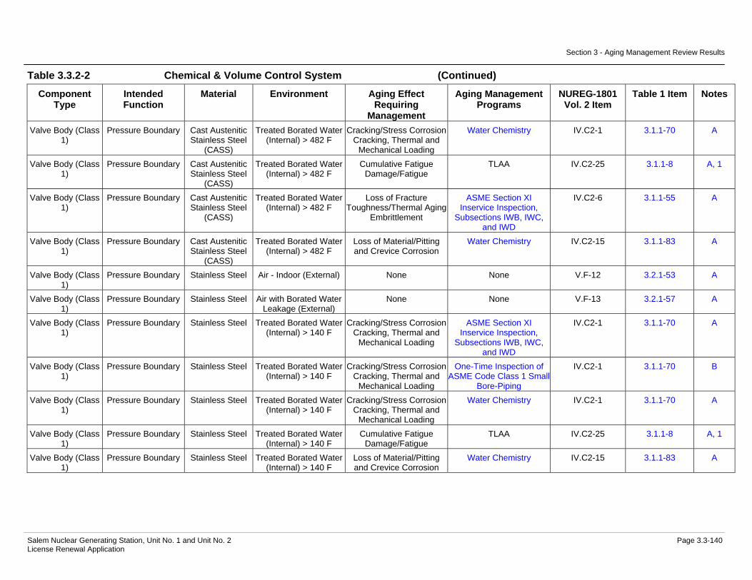
Section 3 - Aging Management Review Results
Salem Nuclear Generating Station, Unit No. 1 and Unit No. 2 Page 3.3-140 License Renewal Application
Table 3.3.2-2 Chemical & Volume Control System (Continued)
Component Type
Intended Function
Material Environment Aging Effect Requiring
Management
Aging Management Programs
NUREG-1801 Vol. 2 Item
Table 1 Item Notes
Valve Body (Class 1)
Pressure Boundary Cast Austenitic Stainless Steel
(CASS)
Treated Borated Water (Internal) > 482 F
Cracking/Stress Corrosion Cracking, Thermal and
Mechanical Loading
Water Chemistry IV.C2-1 3.1.1-70 A
Valve Body (Class 1)
Pressure Boundary Cast Austenitic Stainless Steel
(CASS)
Treated Borated Water (Internal) > 482 F
Cumulative Fatigue Damage/Fatigue
TLAA IV.C2-25 3.1.1-8 A, 1
Valve Body (Class 1)
Pressure Boundary Cast Austenitic Stainless Steel
(CASS)
Treated Borated Water (Internal) > 482 F
Loss of Fracture Toughness/Thermal Aging
Embrittlement
ASME Section XI Inservice Inspection,
Subsections IWB, IWC, and IWD
IV.C2-6 3.1.1-55 A
Valve Body (Class 1)
Pressure Boundary Cast Austenitic Stainless Steel
(CASS)
Treated Borated Water (Internal) > 482 F
Loss of Material/Pitting and Crevice Corrosion
Water Chemistry IV.C2-15 3.1.1-83 A
Valve Body (Class 1)
Pressure Boundary Stainless Steel Air - Indoor (External) None None V.F-12 3.2.1-53 A
Valve Body (Class 1)
Pressure Boundary Stainless Steel Air with Borated Water Leakage (External)
None None V.F-13 3.2.1-57 A
Valve Body (Class 1)
Pressure Boundary Stainless Steel Treated Borated Water (Internal) > 140 F
Cracking/Stress Corrosion Cracking, Thermal and
Mechanical Loading
ASME Section XI Inservice Inspection,
Subsections IWB, IWC, and IWD
IV.C2-1 3.1.1-70 A
Valve Body (Class 1)
Pressure Boundary Stainless Steel Treated Borated Water (Internal) > 140 F
Cracking/Stress Corrosion Cracking, Thermal and
Mechanical Loading
One-Time Inspection of ASME Code Class 1 Small
Bore-Piping
IV.C2-1 3.1.1-70 B
Valve Body (Class 1)
Pressure Boundary Stainless Steel Treated Borated Water (Internal) > 140 F
Cracking/Stress Corrosion Cracking, Thermal and
Mechanical Loading
Water Chemistry IV.C2-1 3.1.1-70 A
Valve Body (Class 1)
Pressure Boundary Stainless Steel Treated Borated Water (Internal) > 140 F
Cumulative Fatigue Damage/Fatigue
TLAA IV.C2-25 3.1.1-8 A, 1
Valve Body (Class 1)
Pressure Boundary Stainless Steel Treated Borated Water (Internal) > 140 F
Loss of Material/Pitting and Crevice Corrosion
Water Chemistry IV.C2-15 3.1.1-83 A

Section 3 - Aging Management Review Results
Salem Nuclear Generating Station, Unit No. 1 and Unit No. 2 Page 3.3-141 License Renewal Application
Notes Definition of Note
A Consistent with NUREG-1801 item for component, material, environment, and aging effect. AMP is consistent with NUREG-1801 AMP.
B Consistent with NUREG-1801 item for component, material, environment, and aging effect. AMP takes some exceptions to NUREG-1801 AMP.
C Component is different, but consistent with NUREG-1801 item for material, environment, and aging effect. AMP is consistent with NUREG-1801 AMP.
D Component is different, but consistent with NUREG-1801 item for material, environment, and aging effect. AMP takes some exceptions to NUREG-1801 AMP.
E Consistent with NUREG-1801 item for material, environment and aging effect, but a different aging management program is credited or NUREG-1801 identifies a plant-specific aging management program.
F Material not in NUREG-1801 for this component.
G Environment not in NUREG-1801 for this component and material.
H Aging effect not in NUREG-1801 for this component, material and environment combination.
I Aging effect in NUREG-1801 for this component, material and environment combination is not applicable.
J Neither the component nor the material and environment combination is evaluated in NUREG-1801.
Plant Specific Notes:
1. The TLAA designation in the Aging Management Program column indicates fatigue of this component is evaluated in Section 4.3.
2. This component is evaluated with the Service Water System.
3. This component is evaluated with the Component Cooling System.
4. NUREG-1801 specifies a plant-specific program. The Periodic Inspection program is used to manage the aging effect(s) applicable to this component type, material, and environment combination.
5. NUREG-1801 specifies a plant specific program. The Water Chemistry program is used to manage the aging effect(s) applicable to this component type, material, and environment combination.
6. The Aboveground Non-Steel Tanks program is substituted to manage the aging effect(s) applicable to this component type, material, and environment combination.
7. The Aboveground Non-Steel Tanks program is used to manage the aging effect(s) applicable to this component type, material, and environment combination.

Section 3 - Aging Management Review Results
Salem Nuclear Generating Station, Unit No. 1 and Unit No. 2 Page 3.3-142 License Renewal Application
Table 3.3.2-3 Chilled Water System
Summary of Aging Management Evaluation
Table 3.3.2-3 Chilled Water System
Component Type
Intended Function
Material Environment Aging Effect Requiring
Management
Aging Management Programs
NUREG-1801 Vol. 2 Item
Table 1 Item Notes
Bolting Mechanical Closure Carbon and Low Alloy Steel
Bolting
Air - Indoor (External) Loss of Material/General, Pitting and Crevice
Corrosion
Bolting Integrity VII.I-4 3.3.1-43 B
Bolting Mechanical Closure Carbon and Low Alloy Steel
Bolting
Air - Indoor (External) Loss of Preload/Thermal Effects, Gasket Creep,
and Self-Loosening
Bolting Integrity VII.I-5 3.3.1-45 B
Bolting Mechanical Closure Carbon and Low Alloy Steel
Bolting
Air with Borated Water Leakage (External)
Loss of Material/Boric Acid Corrosion
Boric Acid Corrosion VII.I-2 3.3.1-89 A
Filter Housing Pressure Boundary Carbon Steel Air - Indoor (External) Loss of Material/General Corrosion
External Surfaces Monitoring
VII.I-8 3.3.1-58 A
Filter Housing Pressure Boundary Carbon Steel Air with Borated Water Leakage (External)
Loss of Material/Boric Acid Corrosion
Boric Acid Corrosion VII.I-10 3.3.1-89 A
Filter Housing Pressure Boundary Carbon Steel Closed Cycle Cooling Water (Internal)
Loss of Material/General, Pitting and Crevice
Corrosion
Closed-Cycle Cooling Water System
VII.C2-14 3.3.1-47 B
Filter Housing Pressure Boundary Gray Cast Iron Air - Indoor (External) Loss of Material/General Corrosion
External Surfaces Monitoring
VII.I-8 3.3.1-58 A
Filter Housing Pressure Boundary Gray Cast Iron Air with Borated Water Leakage (External)
Loss of Material/Boric Acid Corrosion
Boric Acid Corrosion VII.I-10 3.3.1-89 A
Filter Housing Pressure Boundary Gray Cast Iron Closed Cycle Cooling Water (Internal)
Loss of Material/General, Pitting and Crevice
Corrosion
Closed-Cycle Cooling Water System
VII.C2-14 3.3.1-47 B
Filter Housing Pressure Boundary Gray Cast Iron Closed Cycle Cooling Water (Internal)
Loss of Material/Selective Leaching
Selective Leaching of Materials
VII.C2-8 3.3.1-85 A
Flow Element Pressure Boundary Stainless Steel Air - Indoor (External) None None VII.J-15 3.3.1-94 A Flow Element Pressure Boundary Stainless Steel Air with Borated Water
Leakage (External) None None VII.J-16 3.3.1-99 A
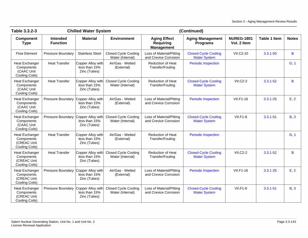
Section 3 - Aging Management Review Results
Salem Nuclear Generating Station, Unit No. 1 and Unit No. 2 Page 3.3-143 License Renewal Application
Table 3.3.2-3 Chilled Water System (Continued)
Component Type
Intended Function
Material Environment Aging Effect Requiring
Management
Aging Management Programs
NUREG-1801 Vol. 2 Item
Table 1 Item Notes
Flow Element Pressure Boundary Stainless Steel Closed Cycle Cooling Water (Internal)
Loss of Material/Pitting and Crevice Corrosion
Closed-Cycle Cooling Water System
VII.C2-10 3.3.1-50 B
Heat Exchanger Components (CAAC Unit
Cooling Coils)
Heat Transfer Copper Alloy with less than 15% Zinc (Tubes)
Air/Gas - Wetted (External)
Reduction of Heat Transfer/Fouling
Periodic Inspection G, 1
Heat Exchanger Components (CAAC Unit
Cooling Coils)
Heat Transfer Copper Alloy with less than 15% Zinc (Tubes)
Closed Cycle Cooling Water (Internal)
Reduction of Heat Transfer/Fouling
Closed-Cycle Cooling Water System
VII.C2-2 3.3.1-52 B
Heat Exchanger Components (CAAC Unit
Cooling Coils)
Pressure Boundary Copper Alloy with less than 15% Zinc (Tubes)
Air/Gas - Wetted (External)
Loss of Material/Pitting and Crevice Corrosion
Periodic Inspection VII.F1-16 3.3.1-25 E, 2
Heat Exchanger Components (CAAC Unit
Cooling Coils)
Pressure Boundary Copper Alloy with less than 15% Zinc (Tubes)
Closed Cycle Cooling Water (Internal)
Loss of Material/Pitting and Crevice Corrosion
Closed-Cycle Cooling Water System
VII.F1-8 3.3.1-51 B, 3
Heat Exchanger Components (CREAC Unit Cooling Coils)
Heat Transfer Copper Alloy with less than 15% Zinc (Tubes)
Air/Gas - Wetted (External)
Reduction of Heat Transfer/Fouling
Periodic Inspection G, 1
Heat Exchanger Components (CREAC Unit Cooling Coils)
Heat Transfer Copper Alloy with less than 15% Zinc (Tubes)
Closed Cycle Cooling Water (Internal)
Reduction of Heat Transfer/Fouling
Closed-Cycle Cooling Water System
VII.C2-2 3.3.1-52 B
Heat Exchanger Components (CREAC Unit Cooling Coils)
Pressure Boundary Copper Alloy with less than 15% Zinc (Tubes)
Air/Gas - Wetted (External)
Loss of Material/Pitting and Crevice Corrosion
Periodic Inspection VII.F1-16 3.3.1-25 E, 2
Heat Exchanger Components (CREAC Unit Cooling Coils)
Pressure Boundary Copper Alloy with less than 15% Zinc (Tubes)
Closed Cycle Cooling Water (Internal)
Loss of Material/Pitting and Crevice Corrosion
Closed-Cycle Cooling Water System
VII.F1-8 3.3.1-51 B, 3

Section 3 - Aging Management Review Results
Salem Nuclear Generating Station, Unit No. 1 and Unit No. 2 Page 3.3-144 License Renewal Application
Table 3.3.2-3 Chilled Water System (Continued)
Component Type
Intended Function
Material Environment Aging Effect Requiring
Management
Aging Management Programs
NUREG-1801 Vol. 2 Item
Table 1 Item Notes
Heat Exchanger Components
(Chiller Condenser)
Evaluated with the Service Water
System
Not Applicable Not Applicable Not Applicable Not applicable 5
Heat Exchanger Components
(Chiller Cooler)
Heat Transfer Copper Alloy with less than 15% Zinc (Tubes)
Air/Gas - Dry (Internal) None None VII.J-4 3.3.1-97 C
Heat Exchanger Components
(Chiller Cooler)
Heat Transfer Copper Alloy with less than 15% Zinc (Tubes)
Closed Cycle Cooling Water (External)
Reduction of Heat Transfer/Fouling
Closed-Cycle Cooling Water System
VII.C2-2 3.3.1-52 B
Heat Exchanger Components
(Chiller Cooler)
Pressure Boundary Carbon Steel (Shellside
Components)
Air - Indoor (External) Loss of Material/General Corrosion
External Surfaces Monitoring
VII.I-8 3.3.1-58 A
Heat Exchanger Components
(Chiller Cooler)
Pressure Boundary Carbon Steel (Shellside
Components)
Air with Borated Water Leakage (External)
Loss of Material/Boric Acid Corrosion
Boric Acid Corrosion VII.I-10 3.3.1-89 A
Heat Exchanger Components
(Chiller Cooler)
Pressure Boundary Carbon Steel (Shellside
Components)
Closed Cycle Cooling Water (Internal)
Loss of Material/General, Pitting and Crevice
Corrosion
Closed-Cycle Cooling Water System
VII.C2-14 3.3.1-47 D
Heat Exchanger Components
(Chiller Cooler)
Pressure Boundary Carbon Steel (Tubesheet)
Air/Gas - Dry (External) None None VII.J-22 3.3.1-98 C
Heat Exchanger Components
(Chiller Cooler)
Pressure Boundary Carbon Steel (Tubesheet)
Closed Cycle Cooling Water (Internal)
Loss of Material/General, Pitting, Crevice and Galvanic Corrosion
Closed-Cycle Cooling Water System
VII.C2-1 3.3.1-48 B
Heat Exchanger Components
(Chiller Cooler)
Pressure Boundary Carbon Steel (Tubeside
Components)
Air - Indoor (External) Loss of Material/General Corrosion
External Surfaces Monitoring
VII.I-8 3.3.1-58 A
Heat Exchanger Components
(Chiller Cooler)
Pressure Boundary Carbon Steel (Tubeside
Components)
Air with Borated Water Leakage (External)
Loss of Material/Boric Acid Corrosion
Boric Acid Corrosion VII.I-10 3.3.1-89 A
Heat Exchanger Components
(Chiller Cooler)
Pressure Boundary Carbon Steel (Tubeside
Components)
Air/Gas - Dry (Internal) None None VII.J-22 3.3.1-98 C

Section 3 - Aging Management Review Results
Salem Nuclear Generating Station, Unit No. 1 and Unit No. 2 Page 3.3-145 License Renewal Application
Table 3.3.2-3 Chilled Water System (Continued)
Component Type
Intended Function
Material Environment Aging Effect Requiring
Management
Aging Management Programs
NUREG-1801 Vol. 2 Item
Table 1 Item Notes
Heat Exchanger Components
(Chiller Cooler)
Pressure Boundary Copper Alloy with less than 15% Zinc (Tubes)
Air/Gas - Dry (Internal) None None VII.J-4 3.3.1-97 C
Heat Exchanger Components
(Chiller Cooler)
Pressure Boundary Copper Alloy with less than 15% Zinc (Tubes)
Closed Cycle Cooling Water (External)
Loss of Material/Pitting and Crevice Corrosion
Closed-Cycle Cooling Water System
VII.F1-8 3.3.1-51 B, 3
Heat Exchanger Components
(Counting Room Cooler)
Leakage Boundary Copper Alloy with less than 15% Zinc (Tubes)
Air/Gas - Wetted (External)
Loss of Material/Pitting and Crevice Corrosion
Periodic Inspection VII.F2-14 3.3.1-25 E, 2
Heat Exchanger Components
(Counting Room Cooler)
Leakage Boundary Copper Alloy with less than 15% Zinc (Tubes)
Closed Cycle Cooling Water (Internal)
Loss of Material/Pitting and Crevice Corrosion
Closed-Cycle Cooling Water System
VII.F1-8 3.3.1-51 B, 3
Heat Exchanger Components
(Emergency Air Compressor Aftercooler)
Heat Transfer Copper Alloy with less than 15% Zinc (Tubes)
Air/Gas - Wetted (External)
Reduction of Heat Transfer/Fouling
Periodic Inspection G, 1
Heat Exchanger Components
(Emergency Air Compressor Aftercooler)
Heat Transfer Copper Alloy with less than 15% Zinc (Tubes)
Closed Cycle Cooling Water (Internal)
Reduction of Heat Transfer/Fouling
Closed-Cycle Cooling Water System
VII.C2-2 3.3.1-52 B
Heat Exchanger Components
(Emergency Air Compressor Aftercooler)
Pressure Boundary Carbon Steel (Shellside
Components)
Air - Indoor (External) Loss of Material/General Corrosion
External Surfaces Monitoring
VII.I-8 3.3.1-58 A
Heat Exchanger Components
(Emergency Air Compressor Aftercooler)
Pressure Boundary Carbon Steel (Shellside
Components)
Air with Borated Water Leakage (External)
Loss of Material/Boric Acid Corrosion
Boric Acid Corrosion VII.I-10 3.3.1-89 A

Section 3 - Aging Management Review Results
Salem Nuclear Generating Station, Unit No. 1 and Unit No. 2 Page 3.3-146 License Renewal Application
Table 3.3.2-3 Chilled Water System (Continued)
Component Type
Intended Function
Material Environment Aging Effect Requiring
Management
Aging Management Programs
NUREG-1801 Vol. 2 Item
Table 1 Item Notes
Heat Exchanger Components
(Emergency Air Compressor Aftercooler)
Pressure Boundary Carbon Steel (Shellside
Components)
Air/Gas - Wetted (Internal)
Loss of Material/General, Pitting and Crevice
Corrosion
Inspection of Internal Surfaces in Miscellaneous
Piping and Ducting Components
VII.G-23 3.3.1-71 C
Heat Exchanger Components
(Emergency Air Compressor Aftercooler)
Pressure Boundary Copper Alloy with less than 15% Zinc (Tubes)
Air/Gas - Wetted (External)
Loss of Material/Pitting and Crevice Corrosion
Periodic Inspection VII.G-9 3.3.1-28 E, 2
Heat Exchanger Components
(Emergency Air Compressor Aftercooler)
Pressure Boundary Copper Alloy with less than 15% Zinc (Tubes)
Closed Cycle Cooling Water (Internal)
Loss of Material/Pitting and Crevice Corrosion
Closed-Cycle Cooling Water System
VII.F1-8 3.3.1-51 B, 3
Heat Exchanger Components
(Emergency Air Compressor Aftercooler)
Pressure Boundary Copper Alloy with less than 15%
Zinc (Tubesheet)
Air/Gas - Wetted (Internal)
Loss of Material/Pitting and Crevice Corrosion
Periodic Inspection VII.G-9 3.3.1-28 E, 2
Heat Exchanger Components
(Emergency Air Compressor Aftercooler)
Pressure Boundary Copper Alloy with less than 15%
Zinc (Tubesheet)
Closed Cycle Cooling Water (External)
Loss of Material/Pitting and Crevice Corrosion
Closed-Cycle Cooling Water System
VII.F1-8 3.3.1-51 B, 3
Heat Exchanger Components
(Emergency Air Compressor Aftercooler)
Pressure Boundary Copper Alloy with less than 15% Zinc (Tubeside Components)
Air - Indoor (External) None None VIII.I-2 3.4.1-41 C
Heat Exchanger Components
(Emergency Air Compressor Aftercooler)
Pressure Boundary Copper Alloy with less than 15% Zinc (Tubeside Components)
Air with Borated Water Leakage (External)
None None VII.J-5 3.3.1-99 C

Section 3 - Aging Management Review Results
Salem Nuclear Generating Station, Unit No. 1 and Unit No. 2 Page 3.3-147 License Renewal Application
Table 3.3.2-3 Chilled Water System (Continued)
Component Type
Intended Function
Material Environment Aging Effect Requiring
Management
Aging Management Programs
NUREG-1801 Vol. 2 Item
Table 1 Item Notes
Heat Exchanger Components
(Emergency Air Compressor Aftercooler)
Pressure Boundary Copper Alloy with less than 15% Zinc (Tubeside Components)
Closed Cycle Cooling Water (Internal)
Loss of Material/Pitting and Crevice Corrosion
Closed-Cycle Cooling Water System
VII.F1-8 3.3.1-51 B, 3
Heat Exchanger Components
(Emergency Air Compressor Intercooler)
Heat Transfer Copper Alloy with less than 15% Zinc (Tubes)
Air/Gas - Wetted (External)
Reduction of Heat Transfer/Fouling
Periodic Inspection G, 1
Heat Exchanger Components
(Emergency Air Compressor Intercooler)
Heat Transfer Copper Alloy with less than 15% Zinc (Tubes)
Closed Cycle Cooling Water (Internal)
Reduction of Heat Transfer/Fouling
Closed-Cycle Cooling Water System
VII.C2-2 3.3.1-52 B
Heat Exchanger Components
(Emergency Air Compressor Intercooler)
Pressure Boundary Copper Alloy with less than 15% Zinc (Tubes)
Air/Gas - Wetted (External)
Loss of Material/Pitting and Crevice Corrosion
Periodic Inspection VII.G-9 3.3.1-28 E, 2
Heat Exchanger Components
(Emergency Air Compressor Intercooler)
Pressure Boundary Copper Alloy with less than 15% Zinc (Tubes)
Closed Cycle Cooling Water (Internal)
Loss of Material/Pitting and Crevice Corrosion
Closed-Cycle Cooling Water System
VII.F1-8 3.3.1-51 B, 3
Heat Exchanger Components
(Emergency Air Compressor Intercooler)
Pressure Boundary Copper Alloy with less than 15%
Zinc (Tubesheet)
Air/Gas - Wetted (Internal)
Loss of Material/Pitting and Crevice Corrosion
Periodic Inspection VII.G-9 3.3.1-28 E, 2
Heat Exchanger Components
(Emergency Air Compressor Intercooler)
Pressure Boundary Copper Alloy with less than 15%
Zinc (Tubesheet)
Closed Cycle Cooling Water (External)
Loss of Material/Pitting and Crevice Corrosion
Closed-Cycle Cooling Water System
VII.F1-8 3.3.1-51 B, 3

Section 3 - Aging Management Review Results
Salem Nuclear Generating Station, Unit No. 1 and Unit No. 2 Page 3.3-148 License Renewal Application
Table 3.3.2-3 Chilled Water System (Continued)
Component Type
Intended Function
Material Environment Aging Effect Requiring
Management
Aging Management Programs
NUREG-1801 Vol. 2 Item
Table 1 Item Notes
Heat Exchanger Components
(Emergency Air Compressor Intercooler)
Pressure Boundary Copper Alloy with less than 15% Zinc (Tubeside Components)
Air - Indoor (External) None None VIII.I-2 3.4.1-41 C
Heat Exchanger Components
(Emergency Air Compressor Intercooler)
Pressure Boundary Copper Alloy with less than 15% Zinc (Tubeside Components)
Air with Borated Water Leakage (External)
None None VII.J-5 3.3.1-99 C
Heat Exchanger Components
(Emergency Air Compressor Intercooler)
Pressure Boundary Copper Alloy with less than 15% Zinc (Tubeside Components)
Closed Cycle Cooling Water (Internal)
Loss of Material/Pitting and Crevice Corrosion
Closed-Cycle Cooling Water System
VII.F1-8 3.3.1-51 B, 3
Heat Exchanger Components
(Emergency Air Compressor Intercooler)
Pressure Boundary Gray Cast Iron (Shellside
Components)
Air - Indoor (External) Loss of Material/General Corrosion
External Surfaces Monitoring
VII.I-8 3.3.1-58 A
Heat Exchanger Components
(Emergency Air Compressor Intercooler)
Pressure Boundary Gray Cast Iron (Shellside
Components)
Air with Borated Water Leakage (External)
Loss of Material/Boric Acid Corrosion
Boric Acid Corrosion VII.I-10 3.3.1-89 A
Heat Exchanger Components
(Emergency Air Compressor Intercooler)
Pressure Boundary Gray Cast Iron (Shellside
Components)
Closed Cycle Cooling Water (Internal)
Loss of Material/General, Pitting, Crevice and Galvanic Corrosion
Closed-Cycle Cooling Water System
VII.C2-1 3.3.1-48 B
Heat Exchanger Components
(Emergency Air Compressor Intercooler)
Pressure Boundary Gray Cast Iron (Shellside
Components)
Closed Cycle Cooling Water (Internal)
Loss of Material/Selective Leaching
Selective Leaching of Materials
VII.C2-8 3.3.1-85 C

Section 3 - Aging Management Review Results
Salem Nuclear Generating Station, Unit No. 1 and Unit No. 2 Page 3.3-149 License Renewal Application
Table 3.3.2-3 Chilled Water System (Continued)
Component Type
Intended Function
Material Environment Aging Effect Requiring
Management
Aging Management Programs
NUREG-1801 Vol. 2 Item
Table 1 Item Notes
Heat Exchanger Components (PAS
Sampling Room Cooler)
Leakage Boundary Copper Alloy with less than 15% Zinc (Tubes)
Air/Gas - Wetted (External)
Loss of Material/Pitting and Crevice Corrosion
Periodic Inspection VII.F2-14 3.3.1-25 E, 2
Heat Exchanger Components (PAS
Sampling Room Cooler)
Leakage Boundary Copper Alloy with less than 15% Zinc (Tubes)
Closed Cycle Cooling Water (Internal)
Loss of Material/Pitting and Crevice Corrosion
Closed-Cycle Cooling Water System
VII.F1-8 3.3.1-51 B, 3
Heat Exchanger Components
(Penetration Area Cooling)
Leakage Boundary Copper Alloy with less than 15% Zinc (Tubes)
Air/Gas - Wetted (External)
Loss of Material/Pitting and Crevice Corrosion
Periodic Inspection VII.F2-14 3.3.1-25 E, 2
Heat Exchanger Components
(Penetration Area Cooling)
Leakage Boundary Copper Alloy with less than 15% Zinc (Tubes)
Closed Cycle Cooling Water (Internal)
Loss of Material/Pitting and Crevice Corrosion
Closed-Cycle Cooling Water System
VII.F1-8 3.3.1-51 B, 3
Heat Exchanger Components
(Primary Laboratory Cooler)
Leakage Boundary Copper Alloy with less than 15% Zinc (Tubes)
Air/Gas - Wetted (External)
Loss of Material/Pitting and Crevice Corrosion
Periodic Inspection VII.F2-14 3.3.1-25 E, 2
Heat Exchanger Components
(Primary Laboratory Cooler)
Leakage Boundary Copper Alloy with less than 15% Zinc (Tubes)
Closed Cycle Cooling Water (Internal)
Loss of Material/Pitting and Crevice Corrosion
Closed-Cycle Cooling Water System
VII.F1-8 3.3.1-51 B, 3
Heat Exchanger Components (Secondary
Laboratory Cooler)
Leakage Boundary Copper Alloy with less than 15% Zinc (Tubes)
Air/Gas - Wetted (External)
Loss of Material/Pitting and Crevice Corrosion
Periodic Inspection VII.F2-14 3.3.1-25 E, 2
Heat Exchanger Components (Secondary
Laboratory Cooler)
Leakage Boundary Copper Alloy with less than 15% Zinc (Tubes)
Closed Cycle Cooling Water (Internal)
Loss of Material/Pitting and Crevice Corrosion
Closed-Cycle Cooling Water System
VII.F1-8 3.3.1-51 B, 3
Piping and Fittings Leakage Boundary Carbon Steel Air - Indoor (External) Loss of Material/General Corrosion
External Surfaces Monitoring
VII.I-8 3.3.1-58 A
Piping and Fittings Leakage Boundary Carbon Steel Air with Borated Water Leakage (External)
Loss of Material/Boric Acid Corrosion
Boric Acid Corrosion VII.I-10 3.3.1-89 A

Section 3 - Aging Management Review Results
Salem Nuclear Generating Station, Unit No. 1 and Unit No. 2 Page 3.3-150 License Renewal Application
Table 3.3.2-3 Chilled Water System (Continued)
Component Type
Intended Function
Material Environment Aging Effect Requiring
Management
Aging Management Programs
NUREG-1801 Vol. 2 Item
Table 1 Item Notes
Piping and Fittings Leakage Boundary Carbon Steel Closed Cycle Cooling Water (Internal)
Loss of Material/General, Pitting and Crevice
Corrosion
Closed-Cycle Cooling Water System
VII.C2-14 3.3.1-47 B
Piping and Fittings Leakage Boundary Stainless Steel Air - Indoor (External) None None VII.J-15 3.3.1-94 A Piping and Fittings Leakage Boundary Stainless Steel Air with Borated Water
Leakage (External) None None VII.J-16 3.3.1-99 A
Piping and Fittings Leakage Boundary Stainless Steel Closed Cycle Cooling Water (Internal)
Loss of Material/Pitting and Crevice Corrosion
Closed-Cycle Cooling Water System
VII.C2-10 3.3.1-50 B
Piping and Fittings Pressure Boundary Carbon Steel Air - Indoor (External) Loss of Material/General Corrosion
External Surfaces Monitoring
VII.I-8 3.3.1-58 A
Piping and Fittings Pressure Boundary Carbon Steel Air with Borated Water Leakage (External)
Loss of Material/Boric Acid Corrosion
Boric Acid Corrosion VII.I-10 3.3.1-89 A
Piping and Fittings Pressure Boundary Carbon Steel Closed Cycle Cooling Water (Internal)
Loss of Material/General, Pitting and Crevice
Corrosion
Closed-Cycle Cooling Water System
VII.C2-14 3.3.1-47 B
Piping and Fittings Pressure Boundary Stainless Steel Air - Indoor (External) None None VII.J-15 3.3.1-94 A Piping and Fittings Pressure Boundary Stainless Steel Air with Borated Water
Leakage (External) None None VII.J-16 3.3.1-99 A
Piping and Fittings Pressure Boundary Stainless Steel Closed Cycle Cooling Water (Internal)
Loss of Material/Pitting and Crevice Corrosion
Closed-Cycle Cooling Water System
VII.C2-10 3.3.1-50 B
Pump Casing (Chilled Water)
Pressure Boundary Stainless Steel Air - Indoor (External) None None VII.J-15 3.3.1-94 A
Pump Casing (Chilled Water)
Pressure Boundary Stainless Steel Air with Borated Water Leakage (External)
None None VII.J-16 3.3.1-99 A
Pump Casing (Chilled Water)
Pressure Boundary Stainless Steel Closed Cycle Cooling Water (Internal)
Loss of Material/Pitting and Crevice Corrosion
Closed-Cycle Cooling Water System
VII.C2-10 3.3.1-50 B
Restricting Orifices Pressure Boundary Stainless Steel Air - Indoor (External) None None VII.J-15 3.3.1-94 A Restricting Orifices Pressure Boundary Stainless Steel Air with Borated Water
Leakage (External) None None VII.J-16 3.3.1-99 A
Restricting Orifices Pressure Boundary Stainless Steel Closed Cycle Cooling Water (Internal)
Loss of Material/Pitting and Crevice Corrosion
Closed-Cycle Cooling Water System
VII.C2-10 3.3.1-50 B
Restricting Orifices Throttle Stainless Steel Air - Indoor (External) None None VII.J-15 3.3.1-94 A

Section 3 - Aging Management Review Results
Salem Nuclear Generating Station, Unit No. 1 and Unit No. 2 Page 3.3-151 License Renewal Application
Table 3.3.2-3 Chilled Water System (Continued)
Component Type
Intended Function
Material Environment Aging Effect Requiring
Management
Aging Management Programs
NUREG-1801 Vol. 2 Item
Table 1 Item Notes
Restricting Orifices Throttle Stainless Steel Air with Borated Water Leakage (External)
None None VII.J-16 3.3.1-99 A
Restricting Orifices Throttle Stainless Steel Closed Cycle Cooling Water (Internal)
Loss of Material/Pitting and Crevice Corrosion
Closed-Cycle Cooling Water System
VII.C2-10 3.3.1-50 B
Sight Glasses Leakage Boundary Glass Air - Indoor (External) None None VII.J-8 3.3.1-93 A Sight Glasses Leakage Boundary Glass Closed Cycle Cooling
Water (Internal) None None G, 4
Silencer Pressure Boundary Carbon Steel Air - Indoor (External) Loss of Material/General Corrosion
External Surfaces Monitoring
VII.I-8 3.3.1-58 A
Silencer Pressure Boundary Carbon Steel Air with Borated Water Leakage (External)
Loss of Material/Boric Acid Corrosion
Boric Acid Corrosion VII.I-10 3.3.1-89 A
Silencer Pressure Boundary Carbon Steel Air/Gas - Dry (Internal) None None VII.J-22 3.3.1-98 A Strainer Filter Stainless Steel Closed Cycle Cooling
Water (External) Loss of Material/Pitting and Crevice Corrosion
Closed-Cycle Cooling Water System
VII.C2-10 3.3.1-50 B
Strainer Filter Stainless Steel Closed Cycle Cooling Water (Internal)
Loss of Material/Pitting and Crevice Corrosion
Closed-Cycle Cooling Water System
VII.C2-10 3.3.1-50 B
Strainer Body Leakage Boundary Carbon Steel Air - Indoor (External) Loss of Material/General Corrosion
External Surfaces Monitoring
VII.I-8 3.3.1-58 A
Strainer Body Leakage Boundary Carbon Steel Air with Borated Water Leakage (External)
Loss of Material/Boric Acid Corrosion
Boric Acid Corrosion VII.I-10 3.3.1-89 A
Strainer Body Leakage Boundary Carbon Steel Closed Cycle Cooling Water (Internal)
Loss of Material/Pitting and Crevice Corrosion
Closed-Cycle Cooling Water System
VII.C2-14 3.3.1-47 B
Strainer Body Pressure Boundary Carbon Steel Air - Indoor (External) Loss of Material/General Corrosion
External Surfaces Monitoring
VII.I-8 3.3.1-58 A
Strainer Body Pressure Boundary Carbon Steel Air with Borated Water Leakage (External)
Loss of Material/Boric Acid Corrosion
Boric Acid Corrosion VII.I-10 3.3.1-89 A
Strainer Body Pressure Boundary Carbon Steel Closed Cycle Cooling Water (Internal)
Loss of Material/General, Pitting and Crevice
Corrosion
Closed-Cycle Cooling Water System
VII.C2-14 3.3.1-47 B
Tanks (Chilled Water Expansion
Tank)
Pressure Boundary Carbon Steel Air - Indoor (External) Loss of Material/General Corrosion
External Surfaces Monitoring
VII.I-8 3.3.1-58 A

Section 3 - Aging Management Review Results
Salem Nuclear Generating Station, Unit No. 1 and Unit No. 2 Page 3.3-152 License Renewal Application
Table 3.3.2-3 Chilled Water System (Continued)
Component Type
Intended Function
Material Environment Aging Effect Requiring
Management
Aging Management Programs
NUREG-1801 Vol. 2 Item
Table 1 Item Notes
Tanks (Chilled Water Expansion
Tank)
Pressure Boundary Carbon Steel Closed Cycle Cooling Water (Internal)
Loss of Material/General, Pitting and Crevice
Corrosion
Closed-Cycle Cooling Water System
VII.C2-14 3.3.1-47 B
Thermowell Leakage Boundary Copper Alloy with 15% Zinc or More
Air - Indoor (External) None None VIII.I-2 3.4.1-41 A
Thermowell Leakage Boundary Copper Alloy with 15% Zinc or More
Air with Borated Water Leakage (External)
Loss of Material/Boric Acid Corrosion
Boric Acid Corrosion VII.I-12 3.3.1-88 A
Thermowell Leakage Boundary Copper Alloy with 15% Zinc or More
Closed Cycle Cooling Water (Internal)
Loss of Material/Pitting and Crevice Corrosion
Closed-Cycle Cooling Water System
VII.C2-4 3.3.1-51 B, 3
Thermowell Pressure Boundary Copper Alloy with 15% Zinc or More
Air - Indoor (External) None None VIII.I-2 3.4.1-41 A
Thermowell Pressure Boundary Copper Alloy with 15% Zinc or More
Air with Borated Water Leakage (External)
Loss of Material/Boric Acid Corrosion
Boric Acid Corrosion VII.I-12 3.3.1-88 A
Thermowell Pressure Boundary Copper Alloy with 15% Zinc or More
Closed Cycle Cooling Water (Internal)
Loss of Material/Pitting and Crevice Corrosion
Closed-Cycle Cooling Water System
VII.C2-4 3.3.1-51 B, 3
Valve Body Leakage Boundary Carbon Steel Air - Indoor (External) Loss of Material/General Corrosion
External Surfaces Monitoring
VII.I-8 3.3.1-58 A
Valve Body Leakage Boundary Carbon Steel Air with Borated Water Leakage (External)
Loss of Material/Boric Acid Corrosion
Boric Acid Corrosion VII.I-10 3.3.1-89 A
Valve Body Leakage Boundary Carbon Steel Closed Cycle Cooling Water (Internal)
Loss of Material/General, Pitting and Crevice
Corrosion
Closed-Cycle Cooling Water System
VII.C2-14 3.3.1-47 B
Valve Body Leakage Boundary Copper Alloy with 15% Zinc or More
Air - Indoor (External) None None VIII.I-2 3.4.1-41 A
Valve Body Leakage Boundary Copper Alloy with 15% Zinc or More
Air with Borated Water Leakage (External)
Loss of Material/Boric Acid Corrosion
Boric Acid Corrosion VII.I-12 3.3.1-88 A
Valve Body Leakage Boundary Copper Alloy with 15% Zinc or More
Closed Cycle Cooling Water (Internal)
Loss of Material/Pitting and Crevice Corrosion
Closed-Cycle Cooling Water System
VII.C2-4 3.3.1-51 B, 3
Valve Body Leakage Boundary Copper Alloy with less than 15%
Zinc
Air - Indoor (External) None None VIII.I-2 3.4.1-41 A
Valve Body Leakage Boundary Copper Alloy with less than 15%
Zinc
Air with Borated Water Leakage (External)
None None VII.J-5 3.3.1-99 A
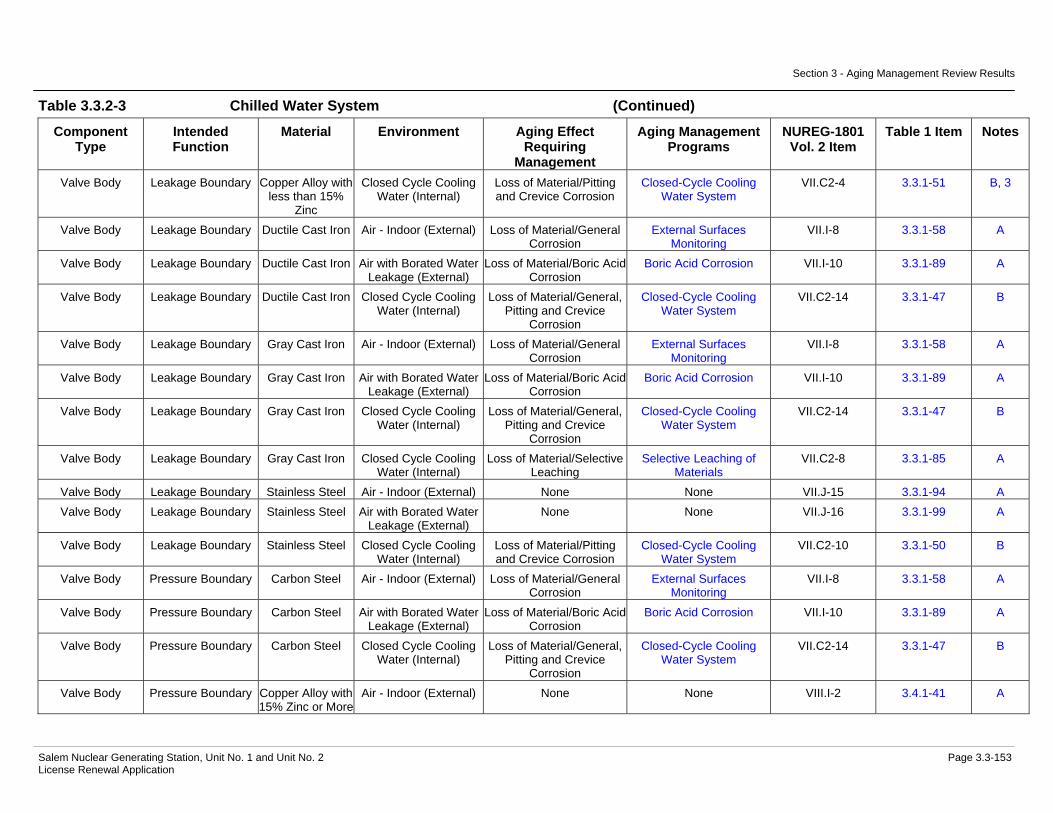
Section 3 - Aging Management Review Results
Salem Nuclear Generating Station, Unit No. 1 and Unit No. 2 Page 3.3-153 License Renewal Application
Table 3.3.2-3 Chilled Water System (Continued)
Component Type
Intended Function
Material Environment Aging Effect Requiring
Management
Aging Management Programs
NUREG-1801 Vol. 2 Item
Table 1 Item Notes
Valve Body Leakage Boundary Copper Alloy with less than 15%
Zinc
Closed Cycle Cooling Water (Internal)
Loss of Material/Pitting and Crevice Corrosion
Closed-Cycle Cooling Water System
VII.C2-4 3.3.1-51 B, 3
Valve Body Leakage Boundary Ductile Cast Iron Air - Indoor (External) Loss of Material/General Corrosion
External Surfaces Monitoring
VII.I-8 3.3.1-58 A
Valve Body Leakage Boundary Ductile Cast Iron Air with Borated Water Leakage (External)
Loss of Material/Boric Acid Corrosion
Boric Acid Corrosion VII.I-10 3.3.1-89 A
Valve Body Leakage Boundary Ductile Cast Iron Closed Cycle Cooling Water (Internal)
Loss of Material/General, Pitting and Crevice
Corrosion
Closed-Cycle Cooling Water System
VII.C2-14 3.3.1-47 B
Valve Body Leakage Boundary Gray Cast Iron Air - Indoor (External) Loss of Material/General Corrosion
External Surfaces Monitoring
VII.I-8 3.3.1-58 A
Valve Body Leakage Boundary Gray Cast Iron Air with Borated Water Leakage (External)
Loss of Material/Boric Acid Corrosion
Boric Acid Corrosion VII.I-10 3.3.1-89 A
Valve Body Leakage Boundary Gray Cast Iron Closed Cycle Cooling Water (Internal)
Loss of Material/General, Pitting and Crevice
Corrosion
Closed-Cycle Cooling Water System
VII.C2-14 3.3.1-47 B
Valve Body Leakage Boundary Gray Cast Iron Closed Cycle Cooling Water (Internal)
Loss of Material/Selective Leaching
Selective Leaching of Materials
VII.C2-8 3.3.1-85 A
Valve Body Leakage Boundary Stainless Steel Air - Indoor (External) None None VII.J-15 3.3.1-94 A Valve Body Leakage Boundary Stainless Steel Air with Borated Water
Leakage (External) None None VII.J-16 3.3.1-99 A
Valve Body Leakage Boundary Stainless Steel Closed Cycle Cooling Water (Internal)
Loss of Material/Pitting and Crevice Corrosion
Closed-Cycle Cooling Water System
VII.C2-10 3.3.1-50 B
Valve Body Pressure Boundary Carbon Steel Air - Indoor (External) Loss of Material/General Corrosion
External Surfaces Monitoring
VII.I-8 3.3.1-58 A
Valve Body Pressure Boundary Carbon Steel Air with Borated Water Leakage (External)
Loss of Material/Boric Acid Corrosion
Boric Acid Corrosion VII.I-10 3.3.1-89 A
Valve Body Pressure Boundary Carbon Steel Closed Cycle Cooling Water (Internal)
Loss of Material/General, Pitting and Crevice
Corrosion
Closed-Cycle Cooling Water System
VII.C2-14 3.3.1-47 B
Valve Body Pressure Boundary Copper Alloy with 15% Zinc or More
Air - Indoor (External) None None VIII.I-2 3.4.1-41 A

Section 3 - Aging Management Review Results
Salem Nuclear Generating Station, Unit No. 1 and Unit No. 2 Page 3.3-154 License Renewal Application
Table 3.3.2-3 Chilled Water System (Continued)
Component Type
Intended Function
Material Environment Aging Effect Requiring
Management
Aging Management Programs
NUREG-1801 Vol. 2 Item
Table 1 Item Notes
Valve Body Pressure Boundary Copper Alloy with 15% Zinc or More
Air with Borated Water Leakage (External)
Loss of Material/Boric Acid Corrosion
Boric Acid Corrosion VII.I-12 3.3.1-88 A
Valve Body Pressure Boundary Copper Alloy with 15% Zinc or More
Closed Cycle Cooling Water (Internal)
Loss of Material/Pitting and Crevice Corrosion
Closed-Cycle Cooling Water System
VII.C2-4 3.3.1-51 B, 3
Valve Body Pressure Boundary Copper Alloy with less than 15%
Zinc
Air - Indoor (External) None None VIII.I-2 3.4.1-41 A
Valve Body Pressure Boundary Copper Alloy with less than 15%
Zinc
Air with Borated Water Leakage (External)
None None VII.J-5 3.3.1-99 A
Valve Body Pressure Boundary Copper Alloy with less than 15%
Zinc
Closed Cycle Cooling Water (Internal)
Loss of Material/Pitting and Crevice Corrosion
Closed-Cycle Cooling Water System
VII.C2-4 3.3.1-51 B, 3
Valve Body Pressure Boundary Ductile Cast Iron Air - Indoor (External) Loss of Material/General Corrosion
External Surfaces Monitoring
VII.I-8 3.3.1-58 A
Valve Body Pressure Boundary Ductile Cast Iron Air with Borated Water Leakage (External)
Loss of Material/Boric Acid Corrosion
Boric Acid Corrosion VII.I-10 3.3.1-89 A
Valve Body Pressure Boundary Ductile Cast Iron Closed Cycle Cooling Water (Internal)
Loss of Material/General, Pitting and Crevice
Corrosion
Closed-Cycle Cooling Water System
VII.C2-14 3.3.1-47 B
Valve Body Pressure Boundary Gray Cast Iron Air - Indoor (External) Loss of Material/General Corrosion
External Surfaces Monitoring
VII.I-8 3.3.1-58 A
Valve Body Pressure Boundary Gray Cast Iron Air with Borated Water Leakage (External)
Loss of Material/Boric Acid Corrosion
Boric Acid Corrosion VII.I-10 3.3.1-89 A
Valve Body Pressure Boundary Gray Cast Iron Closed Cycle Cooling Water (Internal)
Loss of Material/General, Pitting and Crevice
Corrosion
Closed-Cycle Cooling Water System
VII.C2-14 3.3.1-47 B
Valve Body Pressure Boundary Gray Cast Iron Closed Cycle Cooling Water (Internal)
Loss of Material/Selective Leaching
Selective Leaching of Materials
VII.C2-8 3.3.1-85 A
Valve Body Pressure Boundary Stainless Steel Air - Indoor (External) None None VII.J-15 3.3.1-94 A Valve Body Pressure Boundary Stainless Steel Air with Borated Water
Leakage (External) None None VII.J-16 3.3.1-99 A
Valve Body Pressure Boundary Stainless Steel Closed Cycle Cooling Water (Internal)
Loss of Material/Pitting and Crevice Corrosion
Closed-Cycle Cooling Water System
VII.C2-10 3.3.1-50 B
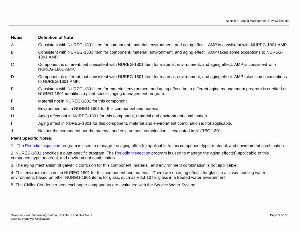
Section 3 - Aging Management Review Results
Salem Nuclear Generating Station, Unit No. 1 and Unit No. 2 Page 3.3-155 License Renewal Application
Notes Definition of Note
A Consistent with NUREG-1801 item for component, material, environment, and aging effect. AMP is consistent with NUREG-1801 AMP.
B Consistent with NUREG-1801 item for component, material, environment, and aging effect. AMP takes some exceptions to NUREG-1801 AMP.
C Component is different, but consistent with NUREG-1801 item for material, environment, and aging effect. AMP is consistent with NUREG-1801 AMP.
D Component is different, but consistent with NUREG-1801 item for material, environment, and aging effect. AMP takes some exceptions to NUREG-1801 AMP.
E Consistent with NUREG-1801 item for material, environment and aging effect, but a different aging management program is credited or NUREG-1801 identifies a plant-specific aging management program.
F Material not in NUREG-1801 for this component.
G Environment not in NUREG-1801 for this component and material.
H Aging effect not in NUREG-1801 for this component, material and environment combination.
I Aging effect in NUREG-1801 for this component, material and environment combination is not applicable.
J Neither the component nor the material and environment combination is evaluated in NUREG-1801.
Plant Specific Notes:
1. The Periodic Inspection program is used to manage the aging effect(s) applicable to this component type, material, and environment combination.
2. NUREG-1801 specifies a plant-specific program. The Periodic Inspection program is used to manage the aging effect(s) applicable to this component type, material, and environment combination.
3. The aging mechanism of galvanic corrosion for this component, material, and environment combination is not applicable.
4. This environment is not in NUREG-1801 for this component and material. There are no aging effects for glass in a closed cooling water environment, based on other NUREG-1801 items for glass, such as VII.J-13 for glass in a treated water environment.
5. The Chiller Condenser heat exchanger components are evaluated with the Service Water System.
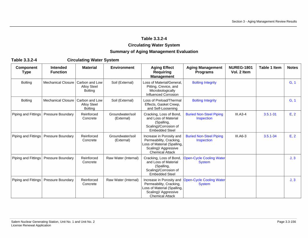
Section 3 - Aging Management Review Results
Salem Nuclear Generating Station, Unit No. 1 and Unit No. 2 Page 3.3-156 License Renewal Application
Table 3.3.2-4 Circulating Water System
Summary of Aging Management Evaluation
Table 3.3.2-4 Circulating Water System
Component Type
Intended Function
Material Environment Aging Effect Requiring
Management
Aging Management Programs
NUREG-1801 Vol. 2 Item
Table 1 Item Notes
Bolting Mechanical Closure Carbon and Low Alloy Steel
Bolting
Soil (External) Loss of Material/General, Pitting, Crevice, and
Microbiologically Influenced Corrosion
Bolting Integrity G, 1
Bolting Mechanical Closure Carbon and Low Alloy Steel
Bolting
Soil (External) Loss of Preload/Thermal Effects, Gasket Creep,
and Self-Loosening
Bolting Integrity G, 1
Piping and Fittings Pressure Boundary Reinforced Concrete
Groundwater/soil (External)
Cracking, Loss of Bond, and Loss of Material
(Spalling, Scaling)/Corrosion of
Embedded Steel
Buried Non-Steel Piping Inspection
III.A3-4 3.5.1-31 E, 2
Piping and Fittings Pressure Boundary Reinforced Concrete
Groundwater/soil (External)
Increase in Porosity and Permeability, Cracking,
Loss of Material (Spalling, Scaling)/ Aggressive
Chemical Attack
Buried Non-Steel Piping Inspection
III.A6-3 3.5.1-34 E, 2
Piping and Fittings Pressure Boundary Reinforced Concrete
Raw Water (Internal) Cracking, Loss of Bond, and Loss of Material
(Spalling, Scaling)/Corrosion of
Embedded Steel
Open-Cycle Cooling Water System
J, 3
Piping and Fittings Pressure Boundary Reinforced Concrete
Raw Water (Internal) Increase in Porosity and Permeability, Cracking,
Loss of Material (Spalling, Scaling)/ Aggressive
Chemical Attack
Open-Cycle Cooling Water System
J, 3

Section 3 - Aging Management Review Results
Salem Nuclear Generating Station, Unit No. 1 and Unit No. 2 Page 3.3-157 License Renewal Application
Table 3.3.2-4 Circulating Water System (Continued)
Component Type
Intended Function
Material Environment Aging Effect Requiring
Management
Aging Management Programs
NUREG-1801 Vol. 2 Item
Table 1 Item Notes
Piping and Fittings Pressure Boundary Reinforced Concrete
Raw Water (Internal) Increase in Porosity and Permeability, Loss of Strength/ Leaching of
Calcium Hydroxide
Open-Cycle Cooling Water System
III.A6-6 3.5.1-37 E, 3
Piping and Fittings Pressure Boundary Reinforced Concrete
Raw Water (Internal) Loss of Material/ Abrasion; Cavitation
Open-Cycle Cooling Water System
E, 3

Section 3 - Aging Management Review Results
Salem Nuclear Generating Station, Unit No. 1 and Unit No. 2 Page 3.3-158 License Renewal Application
Notes Definition of Note
A Consistent with NUREG-1801 item for component, material, environment, and aging effect. AMP is consistent with NUREG-1801 AMP.
B Consistent with NUREG-1801 item for component, material, environment, and aging effect. AMP takes some exceptions to NUREG-1801 AMP.
C Component is different, but consistent with NUREG-1801 item for material, environment, and aging effect. AMP is consistent with NUREG-1801 AMP.
D Component is different, but consistent with NUREG-1801 item for material, environment, and aging effect. AMP takes some exceptions to NUREG-1801 AMP.
E Consistent with NUREG-1801 item for material, environment and aging effect, but a different aging management program is credited or NUREG-1801 identifies a plant-specific aging management program.
F Material not in NUREG-1801 for this component.
G Environment not in NUREG-1801 for this component and material.
H Aging effect not in NUREG-1801 for this component, material and environment combination.
I Aging effect in NUREG-1801 for this component, material and environment combination is not applicable.
J Neither the component nor the material and environment combination is evaluated in NUREG-1801.
Plant Specific Notes:
1. The aging effects for closure bolting in a soil environment include loss of material and loss of preload. External inspections of buried bolting will occur in accordance with the frequency outlined in the Buried Piping Inspection program.
2. The Buried Non-Steel Piping Inspection program is substituted to manage the aging effect(s) applicable to this component type, material, and environment combination.
3. The Open-Cycle Cooling Water System program is substituted to manage the aging effect(s) applicable to this component type, material, and environment combination.

Section 3 - Aging Management Review Results
Salem Nuclear Generating Station, Unit No. 1 and Unit No. 2 Page 3.3-159 License Renewal Application
Table 3.3.2-5 Component Cooling System
Summary of Aging Management Evaluation
Table 3.3.2-5 Component Cooling System
Component Type
Intended Function
Material Environment Aging Effect Requiring
Management
Aging Management Programs
NUREG-1801 Vol. 2 Item
Table 1 Item Notes
Bolting Mechanical Closure Carbon and Low Alloy Steel
Bolting
Air - Indoor (External) Loss of Material/General, Pitting and Crevice
Corrosion
Bolting Integrity VII.I-4 3.3.1-43 B
Bolting Mechanical Closure Carbon and Low Alloy Steel
Bolting
Air - Indoor (External) Loss of Preload/Thermal Effects, Gasket Creep,
and Self-Loosening
Bolting Integrity VII.I-5 3.3.1-45 B
Bolting Mechanical Closure Carbon and Low Alloy Steel
Bolting
Air with Borated Water Leakage (External)
Loss of Material/Boric Acid Corrosion
Boric Acid Corrosion VII.I-2 3.3.1-89 A
Flow Device Pressure Boundary Stainless Steel Air - Indoor (External) None None VII.J-15 3.3.1-94 A Flow Device Pressure Boundary Stainless Steel Air with Borated Water
Leakage (External) None None VII.J-16 3.3.1-99 A
Flow Device Pressure Boundary Stainless Steel Closed Cycle Cooling Water (Internal)
Loss of Material/Pitting and Crevice Corrosion
Closed-Cycle Cooling Water System
VII.C2-10 3.3.1-50 B
Flow Element Leakage Boundary Stainless Steel Air - Indoor (External) None None VII.J-15 3.3.1-94 A Flow Element Leakage Boundary Stainless Steel Air with Borated Water
Leakage (External) None None VII.J-16 3.3.1-99 A
Flow Element Leakage Boundary Stainless Steel Raw Water (Internal) Loss of Material/Pitting, Crevice, and
Microbiologically Induced Corrosion
Periodic Inspection VII.H2-18 3.3.1-80 E, 1
Flow Element Pressure Boundary Stainless Steel Air - Indoor (External) None None VII.J-15 3.3.1-94 A Flow Element Pressure Boundary Stainless Steel Air with Borated Water
Leakage (External) None None VII.J-16 3.3.1-99 A
Flow Element Pressure Boundary Stainless Steel Closed Cycle Cooling Water (Internal)
Loss of Material/Pitting and Crevice Corrosion
Closed-Cycle Cooling Water System
VII.C2-10 3.3.1-50 B

Section 3 - Aging Management Review Results
Salem Nuclear Generating Station, Unit No. 1 and Unit No. 2 Page 3.3-160 License Renewal Application
Table 3.3.2-5 Component Cooling System (Continued)
Component Type
Intended Function
Material Environment Aging Effect Requiring
Management
Aging Management Programs
NUREG-1801 Vol. 2 Item
Table 1 Item Notes
Heat Exchanger Components
(11/21/22 Component
Cooling)
Evaluated with the Service Water
System
Not Applicable Not Applicable Not Applicable Not Applicable 7
Heat Exchanger Components (12
Component Cooling)
Evaluated with the Service Water
System
Not Applicable Not Applicable Not Applicable Not Applicable 7
Heat Exchanger Components (Boric
Acid Evaporator Condenser)
Leakage Boundary Stainless Steel (Tubeside
Components)
Air - Indoor (External) None None VII.J-15 3.3.1-94 C
Heat Exchanger Components (Boric
Acid Evaporator Condenser)
Leakage Boundary Stainless Steel (Tubeside
Components)
Air with Borated Water Leakage (External)
None None VII.J-16 3.3.1-99 C
Heat Exchanger Components (Boric
Acid Evaporator Condenser)
Leakage Boundary Stainless Steel (Tubeside
Components)
Raw Water (Internal) Loss of Material/Pitting, Crevice and
Microbiologically Influenced Corrosion
Periodic Inspection VII.H2-18 3.3.1-80 E, 1
Heat Exchanger Components (Boric
Acid Evaporator Distillate Cooler)
Leakage Boundary Stainless Steel (Tubeside
Components)
Air - Indoor (External) None None VII.J-15 3.3.1-94 C
Heat Exchanger Components (Boric
Acid Evaporator Distillate Cooler)
Leakage Boundary Stainless Steel (Tubeside
Components)
Air with Borated Water Leakage (External)
None None VII.J-16 3.3.1-99 C
Heat Exchanger Components (Boric
Acid Evaporator Distillate Cooler)
Leakage Boundary Stainless Steel (Tubeside
Components)
Raw Water (Internal) Loss of Material/Pitting, Crevice and
Microbiologically Influenced Corrosion
Periodic Inspection VII.H2-18 3.3.1-80 E, 1
Heat Exchanger Components (Boric
Acid Evaporator Vent Condenser)
Leakage Boundary Stainless Steel (Tubeside
Components)
Air - Indoor (External) None None VII.J-15 3.3.1-94 C

Section 3 - Aging Management Review Results
Salem Nuclear Generating Station, Unit No. 1 and Unit No. 2 Page 3.3-161 License Renewal Application
Table 3.3.2-5 Component Cooling System (Continued)
Component Type
Intended Function
Material Environment Aging Effect Requiring
Management
Aging Management Programs
NUREG-1801 Vol. 2 Item
Table 1 Item Notes
Heat Exchanger Components (Boric
Acid Evaporator Vent Condenser)
Leakage Boundary Stainless Steel (Tubeside
Components)
Air with Borated Water Leakage (External)
None None VII.J-16 3.3.1-99 C
Heat Exchanger Components (Boric
Acid Evaporator Vent Condenser)
Leakage Boundary Stainless Steel (Tubeside
Components)
Raw Water (Internal) Loss of Material/Pitting, Crevice and
Microbiologically Influenced Corrosion
Periodic Inspection VII.H2-18 3.3.1-80 E, 1
Heat Exchanger Components
(Excess Letdown)
Pressure Boundary Carbon Steel (Shellside
Components)
Air - Indoor (External) Loss of Material/General Corrosion
External Surfaces Monitoring
VII.I-8 3.3.1-58 A
Heat Exchanger Components
(Excess Letdown)
Pressure Boundary Carbon Steel (Shellside
Components)
Air with Borated Water Leakage (External)
Loss of Material/Boric Acid Corrosion
Boric Acid Corrosion VII.E1-1 3.3.1-89 A
Heat Exchanger Components
(Excess Letdown)
Pressure Boundary Carbon Steel (Shellside
Components)
Closed Cycle Cooling Water (Internal)
Loss of Material/General, Pitting, Crevice and Galvanic Corrosion
Closed-Cycle Cooling Water System
VII.C2-1 3.3.1-48 B
Heat Exchanger Components
(Excess Letdown)
Pressure Boundary Stainless Steel (Tubes)
Closed Cycle Cooling Water (External)
Loss of Material/Pitting and Crevice Corrosion
Closed-Cycle Cooling Water System
VII.C2-10 3.3.1-50 D
Heat Exchanger Components
(Excess Letdown)
Pressure Boundary Stainless Steel (Tubes)
Treated Borated Water (Internal) > 140 F
Cracking/Stress Corrosion Cracking, Cyclic Loading
Water Chemistry VII.E1-9 3.3.1-7 A
Heat Exchanger Components
(Excess Letdown)
Pressure Boundary Stainless Steel (Tubes)
Treated Borated Water (Internal) > 140 F
Loss of Material/Pitting and Crevice Corrosion
Water Chemistry VII.E1-17 3.3.1-91 C
Heat Exchanger Components
(Excess Letdown)
Pressure Boundary Stainless Steel (Tubesheet)
Closed Cycle Cooling Water (External)
Loss of Material/Pitting and Crevice Corrosion
Closed-Cycle Cooling Water System
VII.C2-10 3.3.1-50 D
Heat Exchanger Components
(Excess Letdown)
Pressure Boundary Stainless Steel (Tubesheet)
Treated Borated Water (Internal) > 140 F
Cracking/Stress Corrosion Cracking, Cyclic Loading
Water Chemistry VII.E1-9 3.3.1-7 A
Heat Exchanger Components
(Excess Letdown)
Pressure Boundary Stainless Steel (Tubesheet)
Treated Borated Water (Internal) > 140 F
Loss of Material/Pitting and Crevice Corrosion
Water Chemistry VII.E1-17 3.3.1-91 C

Section 3 - Aging Management Review Results
Salem Nuclear Generating Station, Unit No. 1 and Unit No. 2 Page 3.3-162 License Renewal Application
Table 3.3.2-5 Component Cooling System (Continued)
Component Type
Intended Function
Material Environment Aging Effect Requiring
Management
Aging Management Programs
NUREG-1801 Vol. 2 Item
Table 1 Item Notes
Heat Exchanger Components
(Excess Letdown)
Pressure Boundary Stainless Steel (Tubeside
Components)
Air - Indoor (External) None None VII.J-15 3.3.1-94 C
Heat Exchanger Components
(Excess Letdown)
Pressure Boundary Stainless Steel (Tubeside
Components)
Air with Borated Water Leakage (External)
None None VII.J-16 3.3.1-99 C
Heat Exchanger Components
(Excess Letdown)
Pressure Boundary Stainless Steel (Tubeside
Components)
Treated Borated Water (Internal) > 140 F
Cracking/Stress Corrosion Cracking, Cyclic Loading
Water Chemistry VII.E1-9 3.3.1-7 A
Heat Exchanger Components
(Excess Letdown)
Pressure Boundary Stainless Steel (Tubeside
Components)
Treated Borated Water (Internal) > 140 F
Loss of Material/Pitting and Crevice Corrosion
Water Chemistry VII.E1-17 3.3.1-91 C
Heat Exchanger Components
(Letdown)
Heat Transfer Stainless Steel (Tubes)
Closed Cycle Cooling Water (External)
Reduction of Heat Transfer/Fouling
Closed-Cycle Cooling Water System
VII.C2-3 3.3.1-52 B
Heat Exchanger Components
(Letdown)
Heat Transfer Stainless Steel (Tubes)
Treated Borated Water (Internal) > 140 F
Reduction of Heat Transfer/Fouling
One-Time Inspection VIII.E-13 3.4.1-9 A
Heat Exchanger Components
(Letdown)
Heat Transfer Stainless Steel (Tubes)
Treated Borated Water (Internal) > 140 F
Reduction of Heat Transfer/Fouling
Water Chemistry VIII.E-13 3.4.1-9 A
Heat Exchanger Components
(Letdown)
Pressure Boundary Carbon Steel (Shellside)
Air - Indoor (External) Loss of Material/General Corrosion
External Surfaces Monitoring
VII.I-8 3.3.1-58 A
Heat Exchanger Components
(Letdown)
Pressure Boundary Carbon Steel (Shellside)
Air with Borated Water Leakage (External)
Loss of Material/Boric Acid Corrosion
Boric Acid Corrosion VII.E1-1 3.3.1-89 A
Heat Exchanger Components
(Letdown)
Pressure Boundary Carbon Steel (Shellside)
Closed Cycle Cooling Water (Internal)
Loss of Material/General, Pitting, Crevice and Galvanic Corrosion
Closed-Cycle Cooling Water System
VII.C2-1 3.3.1-48 B
Heat Exchanger Components
(Letdown)
Pressure Boundary Stainless Steel (Tubes)
Closed Cycle Cooling Water (External)
Loss of Material/Pitting and Crevice Corrosion
Closed-Cycle Cooling Water System
VII.C2-10 3.3.1-50 D
Heat Exchanger Components
(Letdown)
Pressure Boundary Stainless Steel (Tubes)
Treated Borated Water (Internal) > 140 F
Cracking/Stress Corrosion Cracking, Cyclic Loading
Water Chemistry VII.E1-9 3.3.1-7 A

Section 3 - Aging Management Review Results
Salem Nuclear Generating Station, Unit No. 1 and Unit No. 2 Page 3.3-163 License Renewal Application
Table 3.3.2-5 Component Cooling System (Continued)
Component Type
Intended Function
Material Environment Aging Effect Requiring
Management
Aging Management Programs
NUREG-1801 Vol. 2 Item
Table 1 Item Notes
Heat Exchanger Components
(Letdown)
Pressure Boundary Stainless Steel (Tubes)
Treated Borated Water (Internal) > 140 F
Loss of Material/Pitting and Crevice Corrosion
Water Chemistry VII.E1-17 3.3.1-91 C
Heat Exchanger Components
(Letdown)
Pressure Boundary Stainless Steel (Tubesheet)
Closed Cycle Cooling Water (External)
Loss of Material/Pitting and Crevice Corrosion
Closed-Cycle Cooling Water System
VII.C2-10 3.3.1-50 D
Heat Exchanger Components
(Letdown)
Pressure Boundary Stainless Steel (Tubesheet)
Treated Borated Water (Internal) > 140 F
Cracking/Stress Corrosion Cracking, Cyclic Loading
Water Chemistry VII.E1-9 3.3.1-7 A
Heat Exchanger Components
(Letdown)
Pressure Boundary Stainless Steel (Tubesheet)
Treated Borated Water (Internal) > 140 F
Loss of Material/Pitting and Crevice Corrosion
Water Chemistry VII.E1-17 3.3.1-91 C
Heat Exchanger Components
(Letdown)
Pressure Boundary Stainless Steel (Tubeside)
Air - Indoor (External) None None VII.J-15 3.3.1-94 C
Heat Exchanger Components
(Letdown)
Pressure Boundary Stainless Steel (Tubeside)
Air with Borated Water Leakage (External)
None None VII.J-16 3.3.1-99 C
Heat Exchanger Components
(Letdown)
Pressure Boundary Stainless Steel (Tubeside)
Treated Borated Water (Internal) > 140 F
Cracking/Stress Corrosion Cracking, Cyclic Loading
Water Chemistry VII.E1-9 3.3.1-7 A
Heat Exchanger Components
(Letdown)
Pressure Boundary Stainless Steel (Tubeside)
Treated Borated Water (Internal) > 140 F
Loss of Material/Pitting and Crevice Corrosion
Water Chemistry VII.E1-17 3.3.1-91 C
Heat Exchanger Components
(Positive Displacement
Pump Lube/Gyrol Oil Cooler)
Heat Transfer Stainless Steel (Tubes)
Closed Cycle Cooling Water (Internal)
Reduction of Heat Transfer/Fouling
Closed-Cycle Cooling Water System
VII.C2-3 3.3.1-52 B
Heat Exchanger Components
(Positive Displacement
Pump Lube/Gyrol Oil Cooler)
Heat Transfer Stainless Steel (Tubes)
Lubricating Oil (External)
Reduction of Heat Transfer/Fouling
Lubricating Oil Analysis VIII.G-12 3.4.1-10 B

Section 3 - Aging Management Review Results
Salem Nuclear Generating Station, Unit No. 1 and Unit No. 2 Page 3.3-164 License Renewal Application
Table 3.3.2-5 Component Cooling System (Continued)
Component Type
Intended Function
Material Environment Aging Effect Requiring
Management
Aging Management Programs
NUREG-1801 Vol. 2 Item
Table 1 Item Notes
Heat Exchanger Components
(Positive Displacement
Pump Lube/Gyrol Oil Cooler)
Heat Transfer Stainless Steel (Tubes)
Lubricating Oil (External)
Reduction of Heat Transfer/Fouling
One-Time Inspection VIII.G-12 3.4.1-10 A
Heat Exchanger Components
(Positive Displacement
Pump Lube/Gyrol Oil Cooler)
Pressure Boundary Carbon Steel (Shellside
Components)
Air - Indoor (External) Loss of Material/General Corrosion
External Surfaces Monitoring
VII.I-8 3.3.1-58 A
Heat Exchanger Components
(Positive Displacement
Pump Lube/Gyrol Oil Cooler)
Pressure Boundary Carbon Steel (Shellside
Components)
Air with Borated Water Leakage (External)
Loss of Material/Boric Acid Corrosion
Boric Acid Corrosion VII.E1-1 3.3.1-89 A
Heat Exchanger Components
(Positive Displacement
Pump Lube/Gyrol Oil Cooler)
Pressure Boundary Carbon Steel (Shellside
Components)
Lubricating Oil (Internal) Loss of Material/General, Pitting and Crevice
Corrosion
Lubricating Oil Analysis VII.C2-13 3.3.1-14 D
Heat Exchanger Components
(Positive Displacement
Pump Lube/Gyrol Oil Cooler)
Pressure Boundary Carbon Steel (Shellside
Components)
Lubricating Oil (Internal) Loss of Material/General, Pitting and Crevice
Corrosion
One-Time Inspection VII.C2-13 3.3.1-14 C
Heat Exchanger Components
(Positive Displacement
Pump Lube/Gyrol Oil Cooler)
Pressure Boundary Stainless Steel (Tubes)
Closed Cycle Cooling Water (Internal)
Loss of Material/Pitting and Crevice Corrosion
Closed-Cycle Cooling Water System
VII.C2-10 3.3.1-50 D

Section 3 - Aging Management Review Results
Salem Nuclear Generating Station, Unit No. 1 and Unit No. 2 Page 3.3-165 License Renewal Application
Table 3.3.2-5 Component Cooling System (Continued)
Component Type
Intended Function
Material Environment Aging Effect Requiring
Management
Aging Management Programs
NUREG-1801 Vol. 2 Item
Table 1 Item Notes
Heat Exchanger Components
(Positive Displacement
Pump Lube/Gyrol Oil Cooler)
Pressure Boundary Stainless Steel (Tubes)
Lubricating Oil (External)
Loss of Material/Pitting and Crevice Corrosion
Lubricating Oil Analysis VII.C2-12 3.3.1-33 D, 2
Heat Exchanger Components
(Positive Displacement
Pump Lube/Gyrol Oil Cooler)
Pressure Boundary Stainless Steel (Tubes)
Lubricating Oil (External)
Loss of Material/Pitting and Crevice Corrosion
One-Time Inspection VII.C2-12 3.3.1-33 C, 2
Heat Exchanger Components (Post Accident Sampling)
Leakage Boundary Stainless Steel Air - Indoor (External) None None VII.J-15 3.3.1-94 C
Heat Exchanger Components (Post Accident Sampling)
Leakage Boundary Stainless Steel Air with Borated Water Leakage (External)
None None VII.J-16 3.3.1-99 C
Heat Exchanger Components (Post Accident Sampling)
Leakage Boundary Stainless Steel Closed Cycle Cooling Water (Internal)
Loss of Material/Pitting and Crevice Corrosion
Closed-Cycle Cooling Water System
VII.C2-10 3.3.1-50 D
Heat Exchanger Components
(Reactor Coolant Pump Bearing Oil)
Pressure Boundary Carbon Steel (Shellside
Components)
Air - Indoor (External) Loss of Material/General Corrosion
External Surfaces Monitoring
VII.I-8 3.3.1-58 A
Heat Exchanger Components
(Reactor Coolant Pump Bearing Oil)
Pressure Boundary Carbon Steel (Shellside
Components)
Air with Borated Water Leakage (External)
Loss of Material/Boric Acid Corrosion
Boric Acid Corrosion VII.E1-1 3.3.1-89 A
Heat Exchanger Components
(Reactor Coolant Pump Bearing Oil)
Pressure Boundary Carbon Steel (Shellside
Components)
Lubricating Oil (Internal) Loss of Material/General, Pitting and Crevice
Corrosion
Lubricating Oil Analysis VII.C2-13 3.3.1-14 D

Section 3 - Aging Management Review Results
Salem Nuclear Generating Station, Unit No. 1 and Unit No. 2 Page 3.3-166 License Renewal Application
Table 3.3.2-5 Component Cooling System (Continued)
Component Type
Intended Function
Material Environment Aging Effect Requiring
Management
Aging Management Programs
NUREG-1801 Vol. 2 Item
Table 1 Item Notes
Heat Exchanger Components
(Reactor Coolant Pump Bearing Oil)
Pressure Boundary Carbon Steel (Shellside
Components)
Lubricating Oil (Internal) Loss of Material/General, Pitting and Crevice
Corrosion
One-Time Inspection VII.C2-13 3.3.1-14 C
Heat Exchanger Components
(Reactor Coolant Pump Bearing Oil)
Pressure Boundary Copper Alloy with less than 15% Zinc (Tubes)
Closed Cycle Cooling Water (Internal)
Loss of Material/Pitting and Crevice Corrosion
Closed-Cycle Cooling Water System
VII.E1-2 3.3.1-51 B, 3
Heat Exchanger Components
(Reactor Coolant Pump Bearing Oil)
Pressure Boundary Copper Alloy with less than 15% Zinc (Tubes)
Lubricating Oil (External)
Loss of Material/Pitting and Crevice Corrosion
Lubricating Oil Analysis VII.C2-5 3.3.1-26 D
Heat Exchanger Components
(Reactor Coolant Pump Bearing Oil)
Pressure Boundary Copper Alloy with less than 15% Zinc (Tubes)
Lubricating Oil (External)
Loss of Material/Pitting and Crevice Corrosion
One-Time Inspection VII.C2-5 3.3.1-26 C
Heat Exchanger Components
(Reactor Coolant Pump Thermal
Barrier)
Heat Transfer Stainless Steel (Tubes)
Closed Cycle Cooling Water (Internal)
Reduction of Heat Transfer/Fouling
Closed-Cycle Cooling Water System
VII.C2-3 3.3.1-52 B
Heat Exchanger Components
(Reactor Coolant Pump Thermal
Barrier)
Heat Transfer Stainless Steel (Tubes)
Treated Borated Water (External) > 140 F
Reduction of Heat Transfer/Fouling
One-Time Inspection VIII.E-13 3.4.1-9 A
Heat Exchanger Components
(Reactor Coolant Pump Thermal
Barrier)
Heat Transfer Stainless Steel (Tubes)
Treated Borated Water (External) > 140 F
Reduction of Heat Transfer/Fouling
Water Chemistry VIII.E-13 3.4.1-9 A
Heat Exchanger Components
(Reactor Coolant Pump Thermal
Barrier)
Pressure Boundary Stainless Steel (Shellside
Component)
Air - Indoor (External) None None VII.J-15 3.3.1-94 C

Section 3 - Aging Management Review Results
Salem Nuclear Generating Station, Unit No. 1 and Unit No. 2 Page 3.3-167 License Renewal Application
Table 3.3.2-5 Component Cooling System (Continued)
Component Type
Intended Function
Material Environment Aging Effect Requiring
Management
Aging Management Programs
NUREG-1801 Vol. 2 Item
Table 1 Item Notes
Heat Exchanger Components
(Reactor Coolant Pump Thermal
Barrier)
Pressure Boundary Stainless Steel (Shellside
Component)
Air with Borated Water Leakage (External)
None None VII.J-16 3.3.1-99 C
Heat Exchanger Components
(Reactor Coolant Pump Thermal
Barrier)
Pressure Boundary Stainless Steel (Shellside
Component)
Treated Borated Water (Internal) > 140 F
Cracking/Stress Corrosion Cracking, Cyclic Loading
Water Chemistry VII.E1-9 3.3.1-7 A
Heat Exchanger Components
(Reactor Coolant Pump Thermal
Barrier)
Pressure Boundary Stainless Steel (Shellside
Component)
Treated Borated Water (Internal) > 140 F
Loss of Material/Pitting and Crevice Corrosion
Water Chemistry VII.E1-17 3.3.1-91 C
Heat Exchanger Components
(Reactor Coolant Pump Thermal
Barrier)
Pressure Boundary Stainless Steel (Tubes)
Closed Cycle Cooling Water (Internal)
Loss of Material/Pitting and Crevice Corrosion
Closed-Cycle Cooling Water System
VII.C2-10 3.3.1-50 D
Heat Exchanger Components
(Reactor Coolant Pump Thermal
Barrier)
Pressure Boundary Stainless Steel (Tubes)
Treated Borated Water (External) > 140 F
Cracking/Stress Corrosion Cracking, Cyclic Loading
Water Chemistry VII.E1-9 3.3.1-7 A
Heat Exchanger Components
(Reactor Coolant Pump Thermal
Barrier)
Pressure Boundary Stainless Steel (Tubes)
Treated Borated Water (External) > 140 F
Loss of Material/Pitting and Crevice Corrosion
Water Chemistry VII.E1-17 3.3.1-91 C
Heat Exchanger Components
(Residual Heat Removal)
Heat Transfer Stainless Steel (Tubes)
Closed Cycle Cooling Water (External)
Reduction of Heat Transfer/Fouling
Closed-Cycle Cooling Water System
V.D1-9 3.2.1-30 B

Section 3 - Aging Management Review Results
Salem Nuclear Generating Station, Unit No. 1 and Unit No. 2 Page 3.3-168 License Renewal Application
Table 3.3.2-5 Component Cooling System (Continued)
Component Type
Intended Function
Material Environment Aging Effect Requiring
Management
Aging Management Programs
NUREG-1801 Vol. 2 Item
Table 1 Item Notes
Heat Exchanger Components
(Residual Heat Removal)
Heat Transfer Stainless Steel (Tubes)
Treated Borated Water (Internal) > 140 F
Reduction of Heat Transfer/Fouling
One-Time Inspection V.A-16 3.2.1-10 A
Heat Exchanger Components
(Residual Heat Removal)
Heat Transfer Stainless Steel (Tubes)
Treated Borated Water (Internal) > 140 F
Reduction of Heat Transfer/Fouling
Water Chemistry V.A-16 3.2.1-10 A
Heat Exchanger Components
(Residual Heat Removal)
Pressure Boundary Carbon Steel (Shellside
Components)
Air - Indoor (External) Loss of Material/General Corrosion
External Surfaces Monitoring
VII.I-8 3.3.1-58 A
Heat Exchanger Components
(Residual Heat Removal)
Pressure Boundary Carbon Steel (Shellside
Components)
Air with Borated Water Leakage (External)
Loss of Material/Boric Acid Corrosion
Boric Acid Corrosion VII.E1-1 3.3.1-89 A
Heat Exchanger Components
(Residual Heat Removal)
Pressure Boundary Carbon Steel (Shellside
Components)
Closed Cycle Cooling Water (Internal)
Loss of Material/General, Pitting, Crevice and Galvanic Corrosion
Closed-Cycle Cooling Water System
VII.C2-1 3.3.1-48 B
Heat Exchanger Components
(Residual Heat Removal)
Pressure Boundary Carbon or Low Alloy Steel with Stainless Steel
Cladding (Tubesheet)
Closed Cycle Cooling Water (Internal)
Loss of Material/Pitting and Crevice Corrosion
Closed-Cycle Cooling Water System
VII.C2-10 3.3.1-50 D
Heat Exchanger Components
(Residual Heat Removal)
Pressure Boundary Carbon or Low Alloy Steel with Stainless Steel
Cladding (Tubesheet)
Treated Borated Water (Internal) > 140 F
Cracking/Stress Corrosion Cracking, Cyclic Loading
Water Chemistry VII.E1-9 3.3.1-7 A
Heat Exchanger Components
(Residual Heat Removal)
Pressure Boundary Carbon or Low Alloy Steel with Stainless Steel
Cladding (Tubesheet)
Treated Borated Water (Internal) > 140 F
Loss of Material/Pitting and Crevice Corrosion
Water Chemistry VII.E1-17 3.3.1-91 C
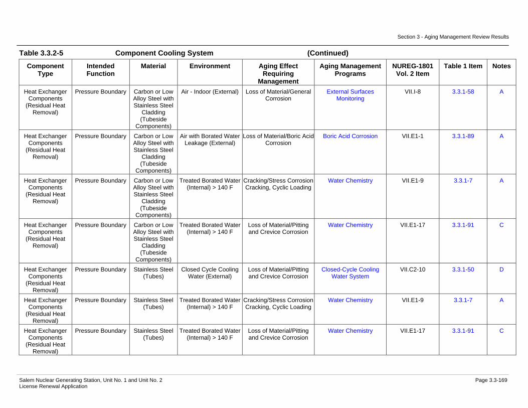
Section 3 - Aging Management Review Results
Salem Nuclear Generating Station, Unit No. 1 and Unit No. 2 Page 3.3-169 License Renewal Application
Table 3.3.2-5 Component Cooling System (Continued)
Component Type
Intended Function
Material Environment Aging Effect Requiring
Management
Aging Management Programs
NUREG-1801 Vol. 2 Item
Table 1 Item Notes
Heat Exchanger Components
(Residual Heat Removal)
Pressure Boundary Carbon or Low Alloy Steel with Stainless Steel
Cladding (Tubeside
Components)
Air - Indoor (External) Loss of Material/General Corrosion
External Surfaces Monitoring
VII.I-8 3.3.1-58 A
Heat Exchanger Components
(Residual Heat Removal)
Pressure Boundary Carbon or Low Alloy Steel with Stainless Steel
Cladding (Tubeside
Components)
Air with Borated Water Leakage (External)
Loss of Material/Boric Acid Corrosion
Boric Acid Corrosion VII.E1-1 3.3.1-89 A
Heat Exchanger Components
(Residual Heat Removal)
Pressure Boundary Carbon or Low Alloy Steel with Stainless Steel
Cladding (Tubeside
Components)
Treated Borated Water (Internal) > 140 F
Cracking/Stress Corrosion Cracking, Cyclic Loading
Water Chemistry VII.E1-9 3.3.1-7 A
Heat Exchanger Components
(Residual Heat Removal)
Pressure Boundary Carbon or Low Alloy Steel with Stainless Steel
Cladding (Tubeside
Components)
Treated Borated Water (Internal) > 140 F
Loss of Material/Pitting and Crevice Corrosion
Water Chemistry VII.E1-17 3.3.1-91 C
Heat Exchanger Components
(Residual Heat Removal)
Pressure Boundary Stainless Steel (Tubes)
Closed Cycle Cooling Water (External)
Loss of Material/Pitting and Crevice Corrosion
Closed-Cycle Cooling Water System
VII.C2-10 3.3.1-50 D
Heat Exchanger Components
(Residual Heat Removal)
Pressure Boundary Stainless Steel (Tubes)
Treated Borated Water (Internal) > 140 F
Cracking/Stress Corrosion Cracking, Cyclic Loading
Water Chemistry VII.E1-9 3.3.1-7 A
Heat Exchanger Components
(Residual Heat Removal)
Pressure Boundary Stainless Steel (Tubes)
Treated Borated Water (Internal) > 140 F
Loss of Material/Pitting and Crevice Corrosion
Water Chemistry VII.E1-17 3.3.1-91 C

Section 3 - Aging Management Review Results
Salem Nuclear Generating Station, Unit No. 1 and Unit No. 2 Page 3.3-170 License Renewal Application
Table 3.3.2-5 Component Cooling System (Continued)
Component Type
Intended Function
Material Environment Aging Effect Requiring
Management
Aging Management Programs
NUREG-1801 Vol. 2 Item
Table 1 Item Notes
Heat Exchanger Components
(Sample)
Heat Transfer Stainless Steel (Tubes)
Closed Cycle Cooling Water (External)
Reduction of Heat Transfer/Fouling
Closed-Cycle Cooling Water System
VII.C2-3 3.3.1-52 B
Heat Exchanger Components
(Sample)
Heat Transfer Stainless Steel (Tubes)
Treated Borated Water (Internal) > 140 F
Reduction of Heat Transfer/Fouling
One-Time Inspection VIII.E-13 3.4.1-9 A
Heat Exchanger Components
(Sample)
Heat Transfer Stainless Steel (Tubes)
Treated Borated Water (Internal) > 140 F
Reduction of Heat Transfer/Fouling
Water Chemistry VIII.E-13 3.4.1-9 A
Heat Exchanger Components
(Sample)
Pressure Boundary Carbon Steel (Shellside
Components)
Air - Indoor (External) Loss of Material/General Corrosion
External Surfaces Monitoring
VII.I-8 3.3.1-58 A
Heat Exchanger Components
(Sample)
Pressure Boundary Carbon Steel (Shellside
Components)
Air with Borated Water Leakage (External)
Loss of Material/Boric Acid Corrosion
Boric Acid Corrosion VII.E1-1 3.3.1-89 A
Heat Exchanger Components
(Sample)
Pressure Boundary Carbon Steel (Shellside
Components)
Closed Cycle Cooling Water (Internal)
Loss of Material/General, Pitting, Crevice and Galvanic Corrosion
Closed-Cycle Cooling Water System
VII.C2-1 3.3.1-48 B
Heat Exchanger Components
(Sample)
Pressure Boundary Stainless Steel (Tubes)
Closed Cycle Cooling Water (External)
Loss of Material/Pitting and Crevice Corrosion
Closed-Cycle Cooling Water System
VII.C2-10 3.3.1-50 D
Heat Exchanger Components
(Sample)
Pressure Boundary Stainless Steel (Tubes)
Treated Borated Water (Internal) > 140 F
Cracking/Stress Corrosion Cracking, Cyclic Loading
Water Chemistry VII.E1-9 3.3.1-7 A
Heat Exchanger Components
(Sample)
Pressure Boundary Stainless Steel (Tubes)
Treated Borated Water (Internal) > 140 F
Loss of Material/Pitting and Crevice Corrosion
Water Chemistry VII.E1-17 3.3.1-91 C
Heat Exchanger Components (Seal
Coolers-Charging/SI
Pumps)
Heat Transfer Stainless Steel (Tubes)
Closed Cycle Cooling Water (External)
Reduction of Heat Transfer/Fouling
Closed-Cycle Cooling Water System
VII.C2-3 3.3.1-52 B

Section 3 - Aging Management Review Results
Salem Nuclear Generating Station, Unit No. 1 and Unit No. 2 Page 3.3-171 License Renewal Application
Table 3.3.2-5 Component Cooling System (Continued)
Component Type
Intended Function
Material Environment Aging Effect Requiring
Management
Aging Management Programs
NUREG-1801 Vol. 2 Item
Table 1 Item Notes
Heat Exchanger Components (Seal
Coolers-Charging/SI
Pumps)
Heat Transfer Stainless Steel (Tubes)
Treated Borated Water (Internal)
Reduction of Heat Transfer/Fouling
One-Time Inspection VIII.E-13 3.4.1-9 A
Heat Exchanger Components (Seal
Coolers-Charging/SI
Pumps)
Heat Transfer Stainless Steel (Tubes)
Treated Borated Water (Internal)
Reduction of Heat Transfer/Fouling
Water Chemistry VIII.E-13 3.4.1-9 A
Heat Exchanger Components (Seal
Coolers-Charging/SI
Pumps)
Pressure Boundary Carbon Steel (Shellside
Components)
Air - Indoor (External) Loss of Material/General Corrosion
External Surfaces Monitoring
VII.I-8 3.3.1-58 A
Heat Exchanger Components (Seal
Coolers-Charging/SI
Pumps)
Pressure Boundary Carbon Steel (Shellside
Components)
Air with Borated Water Leakage (External)
Loss of Material/Boric Acid Corrosion
Boric Acid Corrosion VII.E1-1 3.3.1-89 A
Heat Exchanger Components (Seal
Coolers-Charging/SI
Pumps)
Pressure Boundary Carbon Steel (Shellside
Components)
Closed Cycle Cooling Water (Internal)
Loss of Material/General, Pitting, Crevice and Galvanic Corrosion
Closed-Cycle Cooling Water System
VII.C2-1 3.3.1-48 B
Heat Exchanger Components (Seal
Coolers-Charging/SI
Pumps)
Pressure Boundary Stainless Steel (Tubes)
Closed Cycle Cooling Water (External)
Loss of Material/Pitting and Crevice Corrosion
Closed-Cycle Cooling Water System
VII.C2-10 3.3.1-50 D
Heat Exchanger Components (Seal
Coolers-Charging/SI
Pumps)
Pressure Boundary Stainless Steel (Tubes)
Treated Borated Water (Internal)
Loss of Material/Pitting and Crevice Corrosion
Water Chemistry VII.E1-17 3.3.1-91 C

Section 3 - Aging Management Review Results
Salem Nuclear Generating Station, Unit No. 1 and Unit No. 2 Page 3.3-172 License Renewal Application
Table 3.3.2-5 Component Cooling System (Continued)
Component Type
Intended Function
Material Environment Aging Effect Requiring
Management
Aging Management Programs
NUREG-1801 Vol. 2 Item
Table 1 Item Notes
Heat Exchanger Components (Seal
Coolers-RHR Pumps)
Heat Transfer Stainless Steel (Tubes)
Closed Cycle Cooling Water (External)
Reduction of Heat Transfer/Fouling
Closed-Cycle Cooling Water System
VII.C2-3 3.3.1-52 B
Heat Exchanger Components (Seal
Coolers-RHR Pumps)
Heat Transfer Stainless Steel (Tubes)
Treated Borated Water (Internal) > 140 F
Reduction of Heat Transfer/Fouling
One-Time Inspection VIII.E-13 3.4.1-9 A
Heat Exchanger Components (Seal
Coolers-RHR Pumps)
Heat Transfer Stainless Steel (Tubes)
Treated Borated Water (Internal) > 140 F
Reduction of Heat Transfer/Fouling
Water Chemistry VIII.E-13 3.4.1-9 A
Heat Exchanger Components (Seal
Coolers-RHR Pumps)
Pressure Boundary Carbon Steel (Shellside
Components)
Air - Indoor (External) Loss of Material/General Corrosion
External Surfaces Monitoring
VII.I-8 3.3.1-58 A
Heat Exchanger Components (Seal
Coolers-RHR Pumps)
Pressure Boundary Carbon Steel (Shellside
Components)
Air with Borated Water Leakage (External)
Loss of Material/Boric Acid Corrosion
Boric Acid Corrosion VII.E1-1 3.3.1-89 A
Heat Exchanger Components (Seal
Coolers-RHR Pumps)
Pressure Boundary Carbon Steel (Shellside
Components)
Closed Cycle Cooling Water (Internal)
Loss of Material/General, Pitting, Crevice and Galvanic Corrosion
Closed-Cycle Cooling Water System
VII.C2-1 3.3.1-48 B
Heat Exchanger Components (Seal
Coolers-RHR Pumps)
Pressure Boundary Stainless Steel (Tubes)
Closed Cycle Cooling Water (External)
Loss of Material/Pitting and Crevice Corrosion
Closed-Cycle Cooling Water System
VII.C2-10 3.3.1-50 D
Heat Exchanger Components (Seal
Coolers-RHR Pumps)
Pressure Boundary Stainless Steel (Tubes)
Treated Borated Water (Internal) > 140 F
Cracking/Stress Corrosion Cracking
Water Chemistry VII.E1-20 3.3.1-90 C
Heat Exchanger Components (Seal
Coolers-RHR Pumps)
Pressure Boundary Stainless Steel (Tubes)
Treated Borated Water (Internal) > 140 F
Loss of Material/Pitting and Crevice Corrosion
Water Chemistry VII.E1-17 3.3.1-91 C
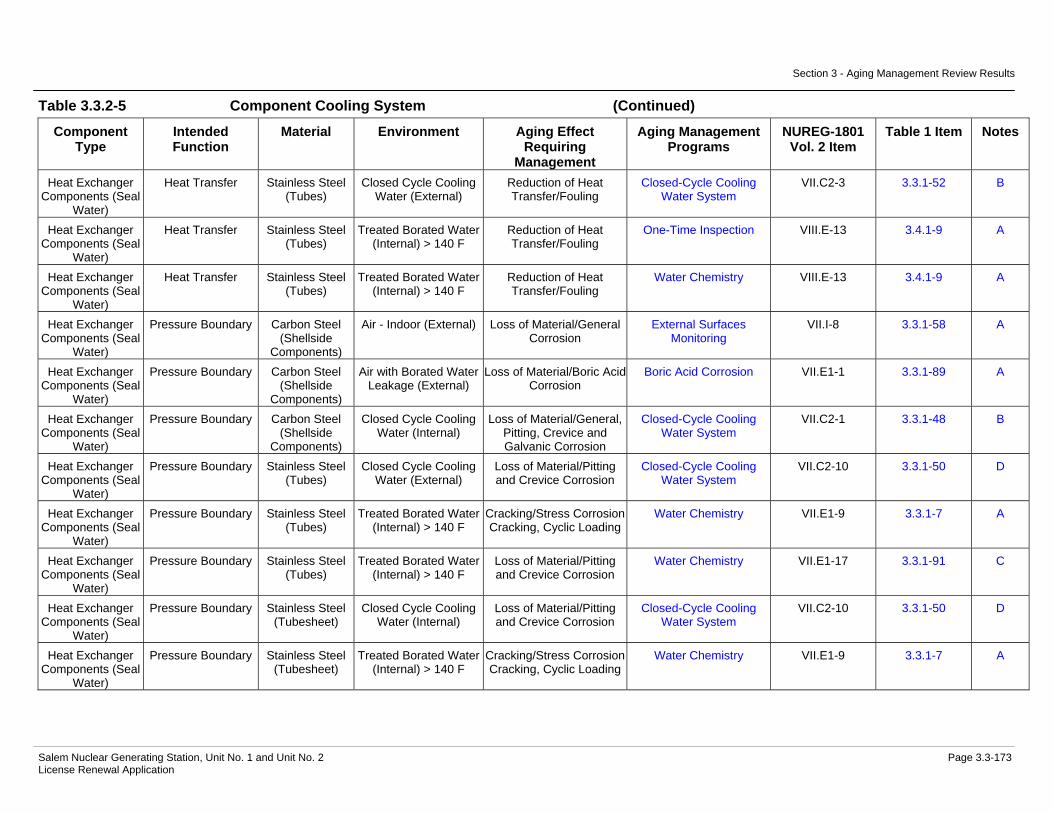
Section 3 - Aging Management Review Results
Salem Nuclear Generating Station, Unit No. 1 and Unit No. 2 Page 3.3-173 License Renewal Application
Table 3.3.2-5 Component Cooling System (Continued)
Component Type
Intended Function
Material Environment Aging Effect Requiring
Management
Aging Management Programs
NUREG-1801 Vol. 2 Item
Table 1 Item Notes
Heat Exchanger Components (Seal
Water)
Heat Transfer Stainless Steel (Tubes)
Closed Cycle Cooling Water (External)
Reduction of Heat Transfer/Fouling
Closed-Cycle Cooling Water System
VII.C2-3 3.3.1-52 B
Heat Exchanger Components (Seal
Water)
Heat Transfer Stainless Steel (Tubes)
Treated Borated Water (Internal) > 140 F
Reduction of Heat Transfer/Fouling
One-Time Inspection VIII.E-13 3.4.1-9 A
Heat Exchanger Components (Seal
Water)
Heat Transfer Stainless Steel (Tubes)
Treated Borated Water (Internal) > 140 F
Reduction of Heat Transfer/Fouling
Water Chemistry VIII.E-13 3.4.1-9 A
Heat Exchanger Components (Seal
Water)
Pressure Boundary Carbon Steel (Shellside
Components)
Air - Indoor (External) Loss of Material/General Corrosion
External Surfaces Monitoring
VII.I-8 3.3.1-58 A
Heat Exchanger Components (Seal
Water)
Pressure Boundary Carbon Steel (Shellside
Components)
Air with Borated Water Leakage (External)
Loss of Material/Boric Acid Corrosion
Boric Acid Corrosion VII.E1-1 3.3.1-89 A
Heat Exchanger Components (Seal
Water)
Pressure Boundary Carbon Steel (Shellside
Components)
Closed Cycle Cooling Water (Internal)
Loss of Material/General, Pitting, Crevice and Galvanic Corrosion
Closed-Cycle Cooling Water System
VII.C2-1 3.3.1-48 B
Heat Exchanger Components (Seal
Water)
Pressure Boundary Stainless Steel (Tubes)
Closed Cycle Cooling Water (External)
Loss of Material/Pitting and Crevice Corrosion
Closed-Cycle Cooling Water System
VII.C2-10 3.3.1-50 D
Heat Exchanger Components (Seal
Water)
Pressure Boundary Stainless Steel (Tubes)
Treated Borated Water (Internal) > 140 F
Cracking/Stress Corrosion Cracking, Cyclic Loading
Water Chemistry VII.E1-9 3.3.1-7 A
Heat Exchanger Components (Seal
Water)
Pressure Boundary Stainless Steel (Tubes)
Treated Borated Water (Internal) > 140 F
Loss of Material/Pitting and Crevice Corrosion
Water Chemistry VII.E1-17 3.3.1-91 C
Heat Exchanger Components (Seal
Water)
Pressure Boundary Stainless Steel (Tubesheet)
Closed Cycle Cooling Water (Internal)
Loss of Material/Pitting and Crevice Corrosion
Closed-Cycle Cooling Water System
VII.C2-10 3.3.1-50 D
Heat Exchanger Components (Seal
Water)
Pressure Boundary Stainless Steel (Tubesheet)
Treated Borated Water (Internal) > 140 F
Cracking/Stress Corrosion Cracking, Cyclic Loading
Water Chemistry VII.E1-9 3.3.1-7 A

Section 3 - Aging Management Review Results
Salem Nuclear Generating Station, Unit No. 1 and Unit No. 2 Page 3.3-174 License Renewal Application
Table 3.3.2-5 Component Cooling System (Continued)
Component Type
Intended Function
Material Environment Aging Effect Requiring
Management
Aging Management Programs
NUREG-1801 Vol. 2 Item
Table 1 Item Notes
Heat Exchanger Components (Seal
Water)
Pressure Boundary Stainless Steel (Tubesheet)
Treated Borated Water (Internal) > 140 F
Loss of Material/Pitting and Crevice Corrosion
Water Chemistry VII.E1-17 3.3.1-91 C
Heat Exchanger Components (Seal
Water)
Pressure Boundary Stainless Steel (Tubeside
Components)
Air - Indoor (External) None None VII.J-15 3.3.1-94 C
Heat Exchanger Components (Seal
Water)
Pressure Boundary Stainless Steel (Tubeside
Components)
Air with Borated Water Leakage (External)
None None VII.J-16 3.3.1-99 C
Heat Exchanger Components (Seal
Water)
Pressure Boundary Stainless Steel (Tubeside
Components)
Treated Borated Water (Internal) > 140 F
Cracking/Stress Corrosion Cracking, Cyclic Loading
Water Chemistry VII.E1-9 3.3.1-7 A
Heat Exchanger Components (Seal
Water)
Pressure Boundary Stainless Steel (Tubeside
Components)
Treated Borated Water (Internal) > 140 F
Loss of Material/Pitting and Crevice Corrosion
Water Chemistry VII.E1-17 3.3.1-91 C
Heat Exchanger Components (Spent Fuel)
Heat Transfer Stainless Steel (Tubes)
Closed Cycle Cooling Water (External)
Reduction of Heat Transfer/Fouling
Closed-Cycle Cooling Water System
VII.C2-3 3.3.1-52 B
Heat Exchanger Components (Spent Fuel)
Heat Transfer Stainless Steel (Tubes)
Treated Borated Water (Internal)
Reduction of Heat Transfer/Fouling
One-Time Inspection VIII.E-13 3.4.1-9 A
Heat Exchanger Components (Spent Fuel)
Heat Transfer Stainless Steel (Tubes)
Treated Borated Water (Internal)
Reduction of Heat Transfer/Fouling
Water Chemistry VIII.E-13 3.4.1-9 A
Heat Exchanger Components (Spent Fuel)
Pressure Boundary Carbon Steel (Shellside
Components)
Air - Indoor (External) Loss of Material/General Corrosion
External Surfaces Monitoring
VII.I-8 3.3.1-58 A
Heat Exchanger Components (Spent Fuel)
Pressure Boundary Carbon Steel (Shellside
Components)
Air with Borated Water Leakage (External)
Loss of Material/Boric Acid Corrosion
Boric Acid Corrosion VII.E1-1 3.3.1-89 A
Heat Exchanger Components (Spent Fuel)
Pressure Boundary Carbon Steel (Shellside
Components)
Closed Cycle Cooling Water (Internal)
Loss of Material/General, Pitting, Crevice and Galvanic Corrosion
Closed-Cycle Cooling Water System
VII.C2-1 3.3.1-48 B
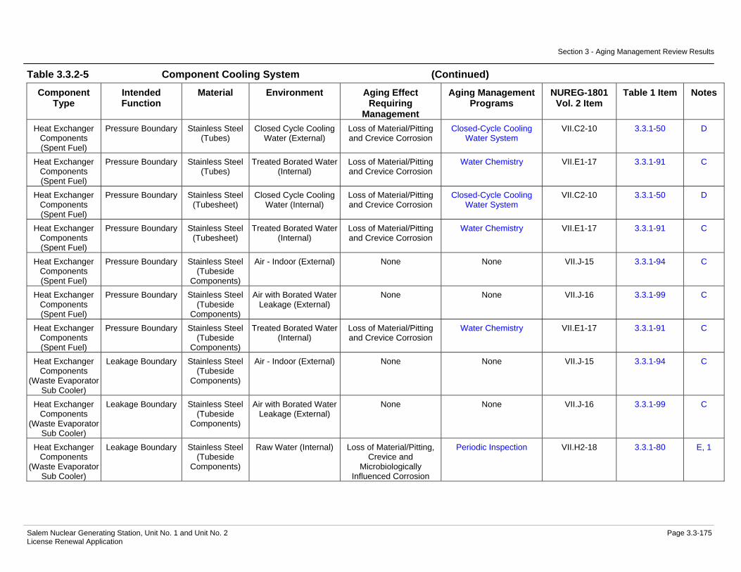
Section 3 - Aging Management Review Results
Salem Nuclear Generating Station, Unit No. 1 and Unit No. 2 Page 3.3-175 License Renewal Application
Table 3.3.2-5 Component Cooling System (Continued)
Component Type
Intended Function
Material Environment Aging Effect Requiring
Management
Aging Management Programs
NUREG-1801 Vol. 2 Item
Table 1 Item Notes
Heat Exchanger Components (Spent Fuel)
Pressure Boundary Stainless Steel (Tubes)
Closed Cycle Cooling Water (External)
Loss of Material/Pitting and Crevice Corrosion
Closed-Cycle Cooling Water System
VII.C2-10 3.3.1-50 D
Heat Exchanger Components (Spent Fuel)
Pressure Boundary Stainless Steel (Tubes)
Treated Borated Water (Internal)
Loss of Material/Pitting and Crevice Corrosion
Water Chemistry VII.E1-17 3.3.1-91 C
Heat Exchanger Components (Spent Fuel)
Pressure Boundary Stainless Steel (Tubesheet)
Closed Cycle Cooling Water (Internal)
Loss of Material/Pitting and Crevice Corrosion
Closed-Cycle Cooling Water System
VII.C2-10 3.3.1-50 D
Heat Exchanger Components (Spent Fuel)
Pressure Boundary Stainless Steel (Tubesheet)
Treated Borated Water (Internal)
Loss of Material/Pitting and Crevice Corrosion
Water Chemistry VII.E1-17 3.3.1-91 C
Heat Exchanger Components (Spent Fuel)
Pressure Boundary Stainless Steel (Tubeside
Components)
Air - Indoor (External) None None VII.J-15 3.3.1-94 C
Heat Exchanger Components (Spent Fuel)
Pressure Boundary Stainless Steel (Tubeside
Components)
Air with Borated Water Leakage (External)
None None VII.J-16 3.3.1-99 C
Heat Exchanger Components (Spent Fuel)
Pressure Boundary Stainless Steel (Tubeside
Components)
Treated Borated Water (Internal)
Loss of Material/Pitting and Crevice Corrosion
Water Chemistry VII.E1-17 3.3.1-91 C
Heat Exchanger Components
(Waste Evaporator Sub Cooler)
Leakage Boundary Stainless Steel (Tubeside
Components)
Air - Indoor (External) None None VII.J-15 3.3.1-94 C
Heat Exchanger Components
(Waste Evaporator Sub Cooler)
Leakage Boundary Stainless Steel (Tubeside
Components)
Air with Borated Water Leakage (External)
None None VII.J-16 3.3.1-99 C
Heat Exchanger Components
(Waste Evaporator Sub Cooler)
Leakage Boundary Stainless Steel (Tubeside
Components)
Raw Water (Internal) Loss of Material/Pitting, Crevice and
Microbiologically Influenced Corrosion
Periodic Inspection VII.H2-18 3.3.1-80 E, 1

Section 3 - Aging Management Review Results
Salem Nuclear Generating Station, Unit No. 1 and Unit No. 2 Page 3.3-176 License Renewal Application
Table 3.3.2-5 Component Cooling System (Continued)
Component Type
Intended Function
Material Environment Aging Effect Requiring
Management
Aging Management Programs
NUREG-1801 Vol. 2 Item
Table 1 Item Notes
Heat Exchanger Components
(Waste Evaporator Vent Condenser)
Leakage Boundary Stainless Steel (Tubeside
Components)
Air - Indoor (External) None None VII.J-15 3.3.1-94 C
Heat Exchanger Components
(Waste Evaporator Vent Condenser)
Leakage Boundary Stainless Steel (Tubeside
Components)
Air with Borated Water Leakage (External)
None None VII.J-16 3.3.1-99 C
Heat Exchanger Components
(Waste Evaporator Vent Condenser)
Leakage Boundary Stainless Steel (Tubeside
Components)
Raw Water (Internal) Loss of Material/Pitting, Crevice and
Microbiologically Influenced Corrosion
Periodic Inspection VII.H2-18 3.3.1-80 E, 1
Heat Exchanger Components
(Waste Evaporator Vent Gas Cooler)
Leakage Boundary Stainless Steel (Tubeside
Components)
Air - Indoor (External) None None VII.J-15 3.3.1-94 C
Heat Exchanger Components
(Waste Evaporator Vent Gas Cooler)
Leakage Boundary Stainless Steel (Tubeside
Components)
Air with Borated Water Leakage (External)
None None VII.J-16 3.3.1-99 C
Heat Exchanger Components
(Waste Evaporator Vent Gas Cooler)
Leakage Boundary Stainless Steel (Tubeside
Components)
Raw Water (Internal) Loss of Material/Pitting, Crevice and
Microbiologically Influenced Corrosion
Periodic Inspection VII.H2-18 3.3.1-80 E, 1
Heat Exchanger Components (Waste Gas
Compressors)
Pressure Boundary Carbon Steel (Shellside
Components)
Air - Indoor (External) Loss of Material/General Corrosion
External Surfaces Monitoring
VII.I-8 3.3.1-58 A
Heat Exchanger Components (Waste Gas
Compressors)
Pressure Boundary Carbon Steel (Shellside
Components)
Air with Borated Water Leakage (External)
Loss of Material/Boric Acid Corrosion
Boric Acid Corrosion VII.E1-1 3.3.1-89 A
Heat Exchanger Components (Waste Gas
Compressors)
Pressure Boundary Carbon Steel (Shellside
Components)
Treated Water (Internal) Loss of Material/General, Pitting and Crevice
Corrosion
One-Time Inspection VIII.E-37 3.4.1-3 A
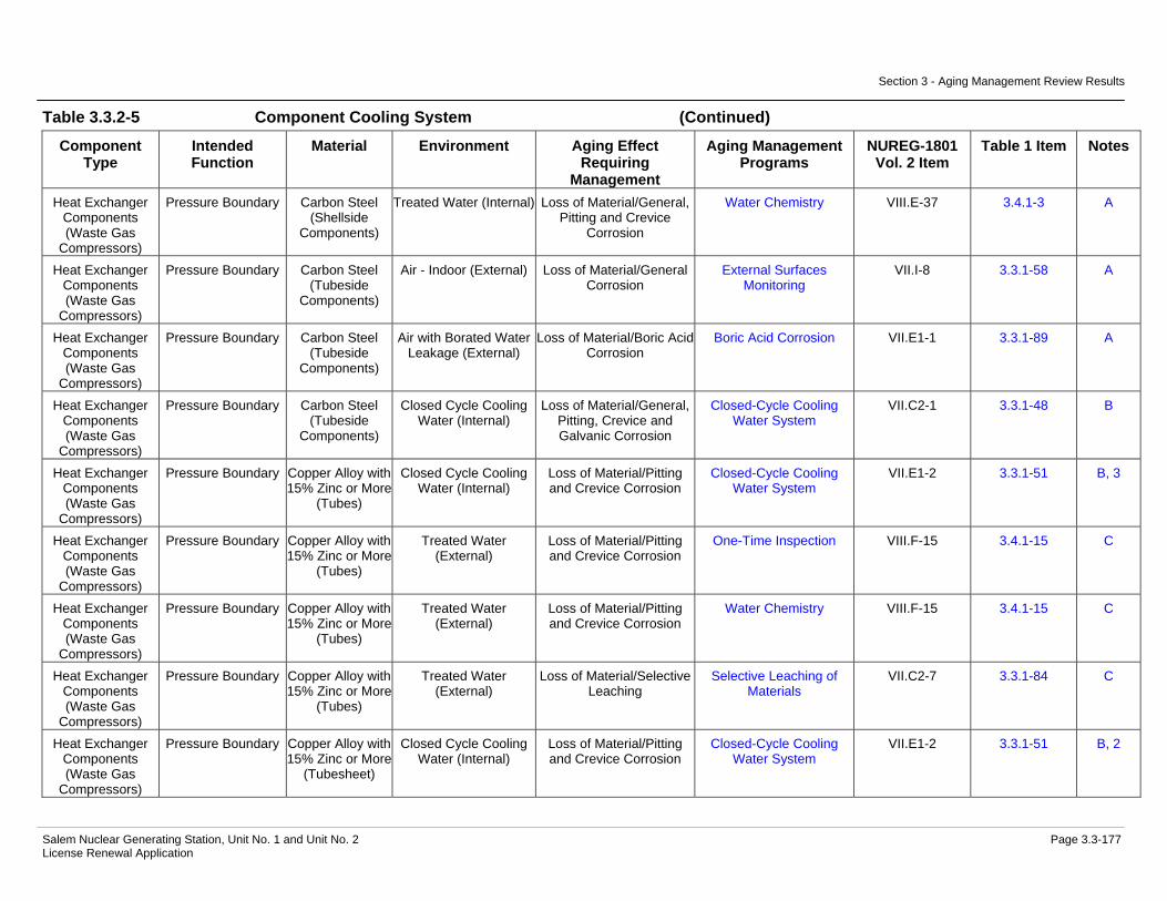
Section 3 - Aging Management Review Results
Salem Nuclear Generating Station, Unit No. 1 and Unit No. 2 Page 3.3-177 License Renewal Application
Table 3.3.2-5 Component Cooling System (Continued)
Component Type
Intended Function
Material Environment Aging Effect Requiring
Management
Aging Management Programs
NUREG-1801 Vol. 2 Item
Table 1 Item Notes
Heat Exchanger Components (Waste Gas
Compressors)
Pressure Boundary Carbon Steel (Shellside
Components)
Treated Water (Internal) Loss of Material/General, Pitting and Crevice
Corrosion
Water Chemistry VIII.E-37 3.4.1-3 A
Heat Exchanger Components (Waste Gas
Compressors)
Pressure Boundary Carbon Steel (Tubeside
Components)
Air - Indoor (External) Loss of Material/General Corrosion
External Surfaces Monitoring
VII.I-8 3.3.1-58 A
Heat Exchanger Components (Waste Gas
Compressors)
Pressure Boundary Carbon Steel (Tubeside
Components)
Air with Borated Water Leakage (External)
Loss of Material/Boric Acid Corrosion
Boric Acid Corrosion VII.E1-1 3.3.1-89 A
Heat Exchanger Components (Waste Gas
Compressors)
Pressure Boundary Carbon Steel (Tubeside
Components)
Closed Cycle Cooling Water (Internal)
Loss of Material/General, Pitting, Crevice and Galvanic Corrosion
Closed-Cycle Cooling Water System
VII.C2-1 3.3.1-48 B
Heat Exchanger Components (Waste Gas
Compressors)
Pressure Boundary Copper Alloy with 15% Zinc or More
(Tubes)
Closed Cycle Cooling Water (Internal)
Loss of Material/Pitting and Crevice Corrosion
Closed-Cycle Cooling Water System
VII.E1-2 3.3.1-51 B, 3
Heat Exchanger Components (Waste Gas
Compressors)
Pressure Boundary Copper Alloy with 15% Zinc or More
(Tubes)
Treated Water (External)
Loss of Material/Pitting and Crevice Corrosion
One-Time Inspection VIII.F-15 3.4.1-15 C
Heat Exchanger Components (Waste Gas
Compressors)
Pressure Boundary Copper Alloy with 15% Zinc or More
(Tubes)
Treated Water (External)
Loss of Material/Pitting and Crevice Corrosion
Water Chemistry VIII.F-15 3.4.1-15 C
Heat Exchanger Components (Waste Gas
Compressors)
Pressure Boundary Copper Alloy with 15% Zinc or More
(Tubes)
Treated Water (External)
Loss of Material/Selective Leaching
Selective Leaching of Materials
VII.C2-7 3.3.1-84 C
Heat Exchanger Components (Waste Gas
Compressors)
Pressure Boundary Copper Alloy with 15% Zinc or More
(Tubesheet)
Closed Cycle Cooling Water (Internal)
Loss of Material/Pitting and Crevice Corrosion
Closed-Cycle Cooling Water System
VII.E1-2 3.3.1-51 B, 2
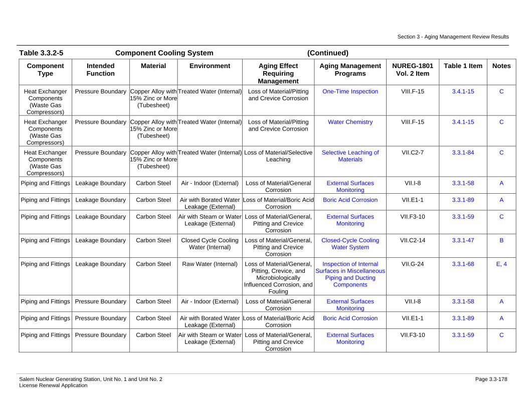
Section 3 - Aging Management Review Results
Salem Nuclear Generating Station, Unit No. 1 and Unit No. 2 Page 3.3-178 License Renewal Application
Table 3.3.2-5 Component Cooling System (Continued)
Component Type
Intended Function
Material Environment Aging Effect Requiring
Management
Aging Management Programs
NUREG-1801 Vol. 2 Item
Table 1 Item Notes
Heat Exchanger Components (Waste Gas
Compressors)
Pressure Boundary Copper Alloy with 15% Zinc or More
(Tubesheet)
Treated Water (Internal) Loss of Material/Pitting and Crevice Corrosion
One-Time Inspection VIII.F-15 3.4.1-15 C
Heat Exchanger Components (Waste Gas
Compressors)
Pressure Boundary Copper Alloy with 15% Zinc or More
(Tubesheet)
Treated Water (Internal) Loss of Material/Pitting and Crevice Corrosion
Water Chemistry VIII.F-15 3.4.1-15 C
Heat Exchanger Components (Waste Gas
Compressors)
Pressure Boundary Copper Alloy with 15% Zinc or More
(Tubesheet)
Treated Water (Internal) Loss of Material/Selective Leaching
Selective Leaching of Materials
VII.C2-7 3.3.1-84 C
Piping and Fittings Leakage Boundary Carbon Steel Air - Indoor (External) Loss of Material/General Corrosion
External Surfaces Monitoring
VII.I-8 3.3.1-58 A
Piping and Fittings Leakage Boundary Carbon Steel Air with Borated Water Leakage (External)
Loss of Material/Boric Acid Corrosion
Boric Acid Corrosion VII.E1-1 3.3.1-89 A
Piping and Fittings Leakage Boundary Carbon Steel Air with Steam or Water Leakage (External)
Loss of Material/General, Pitting and Crevice
Corrosion
External Surfaces Monitoring
VII.F3-10 3.3.1-59 C
Piping and Fittings Leakage Boundary Carbon Steel Closed Cycle Cooling Water (Internal)
Loss of Material/General, Pitting and Crevice
Corrosion
Closed-Cycle Cooling Water System
VII.C2-14 3.3.1-47 B
Piping and Fittings Leakage Boundary Carbon Steel Raw Water (Internal) Loss of Material/General, Pitting, Crevice, and
Microbiologically Influenced Corrosion, and
Fouling
Inspection of Internal Surfaces in Miscellaneous
Piping and Ducting Components
VII.G-24 3.3.1-68 E, 4
Piping and Fittings Pressure Boundary Carbon Steel Air - Indoor (External) Loss of Material/General Corrosion
External Surfaces Monitoring
VII.I-8 3.3.1-58 A
Piping and Fittings Pressure Boundary Carbon Steel Air with Borated Water Leakage (External)
Loss of Material/Boric Acid Corrosion
Boric Acid Corrosion VII.E1-1 3.3.1-89 A
Piping and Fittings Pressure Boundary Carbon Steel Air with Steam or Water Leakage (External)
Loss of Material/General, Pitting and Crevice
Corrosion
External Surfaces Monitoring
VII.F3-10 3.3.1-59 C

Section 3 - Aging Management Review Results
Salem Nuclear Generating Station, Unit No. 1 and Unit No. 2 Page 3.3-179 License Renewal Application
Table 3.3.2-5 Component Cooling System (Continued)
Component Type
Intended Function
Material Environment Aging Effect Requiring
Management
Aging Management Programs
NUREG-1801 Vol. 2 Item
Table 1 Item Notes
Piping and Fittings Pressure Boundary Carbon Steel Closed Cycle Cooling Water (Internal)
Cumulative Fatigue Damage/Fatigue
TLAA VIII.D1-7 3.4.1-1 A, 5
Piping and Fittings Pressure Boundary Carbon Steel Closed Cycle Cooling Water (Internal)
Loss of Material/General, Pitting and Crevice
Corrosion
Closed-Cycle Cooling Water System
VII.C2-14 3.3.1-47 B
Piping and Fittings Pressure Boundary Carbon Steel Treated Water (Internal) Loss of Material/General, Pitting and Crevice
Corrosion
One-Time Inspection VIII.E-34 3.4.1-4 A
Piping and Fittings Pressure Boundary Carbon Steel Treated Water (Internal) Loss of Material/General, Pitting and Crevice
Corrosion
Water Chemistry VIII.E-34 3.4.1-4 A
Piping and Fittings Pressure Boundary Copper Alloy with less than 15%
Zinc
Air - Indoor (External) None None VIII.I-2 3.4.1-41 A
Piping and Fittings Pressure Boundary Copper Alloy with less than 15%
Zinc
Air with Borated Water Leakage (External)
None None VII.J-5 3.3.1-99 A
Piping and Fittings Pressure Boundary Copper Alloy with less than 15%
Zinc
Closed Cycle Cooling Water (Internal)
Loss of Material/Pitting and Crevice Corrosion
Closed-Cycle Cooling Water System
VII.C2-4 3.3.1-51 B, 3
Piping and Fittings Pressure Boundary Stainless Steel Air - Indoor (External) None None VII.J-15 3.3.1-94 A Piping and Fittings Pressure Boundary Stainless Steel Air with Borated Water
Leakage (External) None None VII.J-16 3.3.1-99 A
Piping and Fittings Pressure Boundary Stainless Steel Air with Steam or Water Leakage (External)
Loss of Material/Pitting and Crevice Corrosion
Periodic Inspection VII.F3-1 3.3.1-27 E, 6
Piping and Fittings Pressure Boundary Stainless Steel Closed Cycle Cooling Water (Internal)
Loss of Material/Pitting and Crevice Corrosion
Closed-Cycle Cooling Water System
VII.C2-10 3.3.1-50 B
Piping and Fittings Structural Support Carbon Steel Air - Indoor (External) Loss of Material/General Corrosion
External Surfaces Monitoring
VII.I-8 3.3.1-58 A
Piping and Fittings Structural Support Carbon Steel Air with Borated Water Leakage (External)
Loss of Material/Boric Acid Corrosion
Boric Acid Corrosion VII.E1-1 3.3.1-89 A
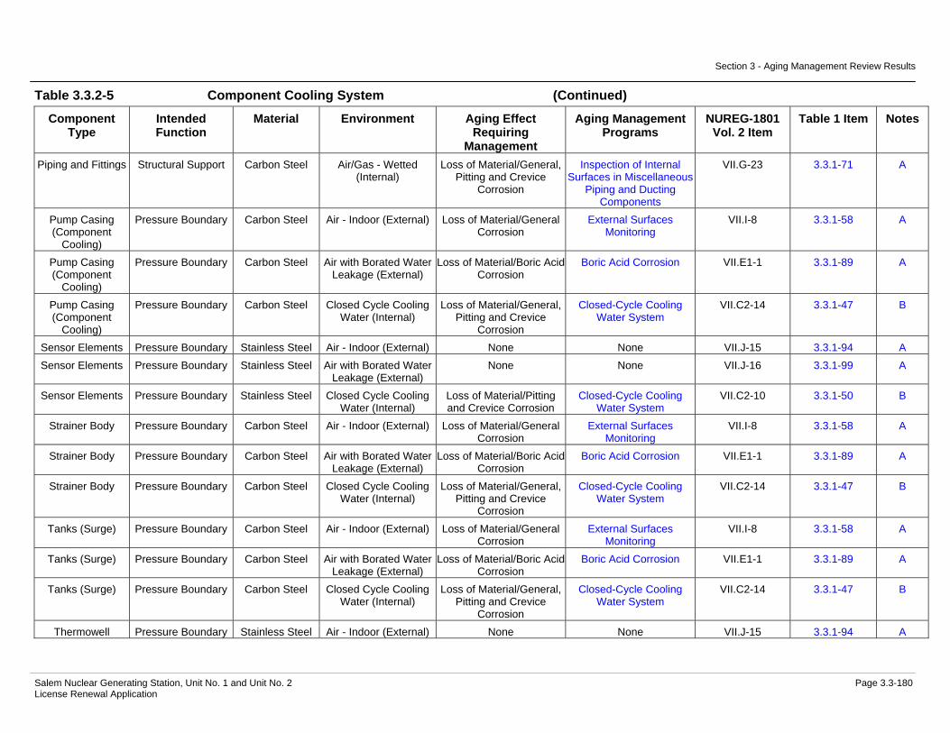
Section 3 - Aging Management Review Results
Salem Nuclear Generating Station, Unit No. 1 and Unit No. 2 Page 3.3-180 License Renewal Application
Table 3.3.2-5 Component Cooling System (Continued)
Component Type
Intended Function
Material Environment Aging Effect Requiring
Management
Aging Management Programs
NUREG-1801 Vol. 2 Item
Table 1 Item Notes
Piping and Fittings Structural Support Carbon Steel Air/Gas - Wetted (Internal)
Loss of Material/General, Pitting and Crevice
Corrosion
Inspection of Internal Surfaces in Miscellaneous
Piping and Ducting Components
VII.G-23 3.3.1-71 A
Pump Casing (Component
Cooling)
Pressure Boundary Carbon Steel Air - Indoor (External) Loss of Material/General Corrosion
External Surfaces Monitoring
VII.I-8 3.3.1-58 A
Pump Casing (Component
Cooling)
Pressure Boundary Carbon Steel Air with Borated Water Leakage (External)
Loss of Material/Boric Acid Corrosion
Boric Acid Corrosion VII.E1-1 3.3.1-89 A
Pump Casing (Component
Cooling)
Pressure Boundary Carbon Steel Closed Cycle Cooling Water (Internal)
Loss of Material/General, Pitting and Crevice
Corrosion
Closed-Cycle Cooling Water System
VII.C2-14 3.3.1-47 B
Sensor Elements Pressure Boundary Stainless Steel Air - Indoor (External) None None VII.J-15 3.3.1-94 A Sensor Elements Pressure Boundary Stainless Steel Air with Borated Water
Leakage (External) None None VII.J-16 3.3.1-99 A
Sensor Elements Pressure Boundary Stainless Steel Closed Cycle Cooling Water (Internal)
Loss of Material/Pitting and Crevice Corrosion
Closed-Cycle Cooling Water System
VII.C2-10 3.3.1-50 B
Strainer Body Pressure Boundary Carbon Steel Air - Indoor (External) Loss of Material/General Corrosion
External Surfaces Monitoring
VII.I-8 3.3.1-58 A
Strainer Body Pressure Boundary Carbon Steel Air with Borated Water Leakage (External)
Loss of Material/Boric Acid Corrosion
Boric Acid Corrosion VII.E1-1 3.3.1-89 A
Strainer Body Pressure Boundary Carbon Steel Closed Cycle Cooling Water (Internal)
Loss of Material/General, Pitting and Crevice
Corrosion
Closed-Cycle Cooling Water System
VII.C2-14 3.3.1-47 B
Tanks (Surge) Pressure Boundary Carbon Steel Air - Indoor (External) Loss of Material/General Corrosion
External Surfaces Monitoring
VII.I-8 3.3.1-58 A
Tanks (Surge) Pressure Boundary Carbon Steel Air with Borated Water Leakage (External)
Loss of Material/Boric Acid Corrosion
Boric Acid Corrosion VII.E1-1 3.3.1-89 A
Tanks (Surge) Pressure Boundary Carbon Steel Closed Cycle Cooling Water (Internal)
Loss of Material/General, Pitting and Crevice
Corrosion
Closed-Cycle Cooling Water System
VII.C2-14 3.3.1-47 B
Thermowell Pressure Boundary Stainless Steel Air - Indoor (External) None None VII.J-15 3.3.1-94 A

Section 3 - Aging Management Review Results
Salem Nuclear Generating Station, Unit No. 1 and Unit No. 2 Page 3.3-181 License Renewal Application
Table 3.3.2-5 Component Cooling System (Continued)
Component Type
Intended Function
Material Environment Aging Effect Requiring
Management
Aging Management Programs
NUREG-1801 Vol. 2 Item
Table 1 Item Notes
Thermowell Pressure Boundary Stainless Steel Air with Borated Water Leakage (External)
None None VII.J-16 3.3.1-99 A
Thermowell Pressure Boundary Stainless Steel Closed Cycle Cooling Water (Internal)
Loss of Material/Pitting and Crevice Corrosion
Closed-Cycle Cooling Water System
VII.C2-10 3.3.1-50 B
Valve Body Leakage Boundary Carbon Steel Air - Indoor (External) Loss of Material/General Corrosion
External Surfaces Monitoring
VII.I-8 3.3.1-58 A
Valve Body Leakage Boundary Carbon Steel Air with Borated Water Leakage (External)
Loss of Material/Boric Acid Corrosion
Boric Acid Corrosion VII.E1-1 3.3.1-89 A
Valve Body Leakage Boundary Carbon Steel Raw Water (Internal) Loss of Material/General, Pitting, Crevice, and
Microbiologically Induced Corrosion, and Fouling
Inspection of Internal Surfaces in Miscellaneous
Piping and Ducting Components
VII.G-24 3.3.1-68 E, 4
Valve Body Pressure Boundary Aluminum Bronze with 8% Al or
more
Air - Indoor (External) None None VIII.I-2 3.4.1-41 A
Valve Body Pressure Boundary Aluminum Bronze with 8% Al or
more
Air with Borated Water Leakage (External)
Loss of Material/Boric Acid Corrosion
Boric Acid Corrosion VII.I-12 3.3.1-88 A
Valve Body Pressure Boundary Aluminum Bronze with 8% Al or
more
Closed Cycle Cooling Water (Internal)
Loss of Material/Pitting and Crevice Corrosion
Closed-Cycle Cooling Water System
VII.C2-4 3.3.1-51 B, 3
Valve Body Pressure Boundary Carbon Steel Air - Indoor (External) Loss of Material/General Corrosion
External Surfaces Monitoring
VII.I-8 3.3.1-58 A
Valve Body Pressure Boundary Carbon Steel Air with Borated Water Leakage (External)
Loss of Material/Boric Acid Corrosion
Boric Acid Corrosion VII.E1-1 3.3.1-89 A
Valve Body Pressure Boundary Carbon Steel Closed Cycle Cooling Water (Internal)
Loss of Material/General, Pitting and Crevice
Corrosion
Closed-Cycle Cooling Water System
VII.C2-14 3.3.1-47 B
Valve Body Pressure Boundary Carbon Steel Treated Water (Internal) Loss of Material/General, Pitting and Crevice
Corrosion
One-Time Inspection VIII.E-34 3.4.1-4 A
Valve Body Pressure Boundary Carbon Steel Treated Water (Internal) Loss of Material/General, Pitting and Crevice
Corrosion
Water Chemistry VIII.E-34 3.4.1-4 A
Valve Body Pressure Boundary Stainless Steel Air - Indoor (External) None None VII.J-15 3.3.1-94 A

Section 3 - Aging Management Review Results
Salem Nuclear Generating Station, Unit No. 1 and Unit No. 2 Page 3.3-182 License Renewal Application
Table 3.3.2-5 Component Cooling System (Continued)
Component Type
Intended Function
Material Environment Aging Effect Requiring
Management
Aging Management Programs
NUREG-1801 Vol. 2 Item
Table 1 Item Notes
Thermowell Pressure Boundary Stainless Steel Air with Borated Water Leakage (External)
None None VII.J-16 3.3.1-99 A
Thermowell Pressure Boundary Stainless Steel Closed Cycle Cooling Water (Internal)
Loss of Material/Pitting and Crevice Corrosion
Closed-Cycle Cooling Water System
VII.C2-10 3.3.1-50 B
Notes Definition of Note
A Consistent with NUREG-1801 item for component, material, environment, and aging effect. AMP is consistent with NUREG-1801 AMP.
B Consistent with NUREG-1801 item for component, material, environment, and aging effect. AMP takes some exceptions to NUREG-1801 AMP.
C Component is different, but consistent with NUREG-1801 item for material, environment, and aging effect. AMP is consistent with NUREG-1801 AMP.
D Component is different, but consistent with NUREG-1801 item for material, environment, and aging effect. AMP takes some exceptions to NUREG-1801 AMP.
E Consistent with NUREG-1801 item for material, environment and aging effect, but a different aging management program is credited or NUREG-1801 identifies a plant-specific aging management program.
F Material not in NUREG-1801 for this component.
G Environment not in NUREG-1801 for this component and material.
H Aging effect not in NUREG-1801 for this component, material and environment combination.
I Aging effect in NUREG-1801 for this component, material and environment combination is not applicable.
J Neither the component nor the material and environment combination is evaluated in NUREG-1801.
Plant Specific Notes:
1. The Periodic Inspection program is substituted to manage the aging effect(s) applicable to this component type, material, and environment combination.
2. Loss of material due to microbiologically-influenced corrosion is not applicable for stainless steel components in a Lubricating Oil environment. Industry and Plant operating experience indicates that the potential for significant degradation of lubricating oil systems due to microbiologically- influenced corrosion is minimal. Lubricating oil systems are maintained to high cleanliness standards by design. Lubricating oil formulations include

Section 3 - Aging Management Review Results
Salem Nuclear Generating Station, Unit No. 1 and Unit No. 2 Page 3.3-183 License Renewal Application
corrosion inhibitors, and the potential for water and contaminant intrusion is low compared to fuel oil systems; where the bulk storage, delivery and transport of the fuel oil increases the likelihood of moisture and microorganism contamination.
3. The aging mechanism of galvanic corrosion for this component, material, and environment combination is not applicable.
4. The Inspection of Internal Surfaces in Miscellaneous Piping and Ducting Components program is substituted to manage the aging effect(s) applicable to this component type, material, and environment combination.
5. The TLAA designation in the Aging Management Program column indicates fatigue of this component is evaluated in Section 4.3.
6. NUREG-1801 specifies a plant-specific program. The Periodic Inspection program is used to manage the aging effect(s) applicable to this component type, material, and environment combination.
7. The 11/21/22 Component Cooling and 12 Component Cooling heat exchanger components are evaluated with the Service Water System.

Section 3 - Aging Management Review Results
Salem Nuclear Generating Station, Unit No. 1 and Unit No. 2 Page 3.3-184 License Renewal Application
Table 3.3.2-6 Compressed Air System
Summary of Aging Management Evaluation
Table 3.3.2-6 Compressed Air System
Component Type
Intended Function
Material Environment Aging Effect Requiring
Management
Aging Management Programs
NUREG-1801 Vol. 2 Item
Table 1 Item Notes
Accumulator Pressure Boundary Carbon Steel Air - Indoor (External) Loss of Material/General Corrosion
External Surfaces Monitoring
VII.I-8 3.3.1-58 A
Accumulator Pressure Boundary Carbon Steel Air with Borated Water Leakage (External)
Loss of Material/Boric Acid Corrosion
Boric Acid Corrosion VII.I-10 3.3.1-89 A
Accumulator Pressure Boundary Carbon Steel Air/Gas - Dry (Internal) None Compressed Air Monitoring
VII.J-22 3.3.1-98 E, 1
Accumulator Pressure Boundary Carbon Steel Air/Gas - Wetted (Internal)
Loss of Material/General, Pitting and Crevice
Corrosion
Compressed Air Monitoring
VII.G-23 3.3.1-71 E, 2
Accumulator Pressure Boundary Stainless Steel Air - Indoor (External) None None VII.J-15 3.3.1-94 A Accumulator Pressure Boundary Stainless Steel Air with Borated Water
Leakage (External) None None VII.J-16 3.3.1-99 A
Accumulator Pressure Boundary Stainless Steel Air/Gas - Dry (Internal) None Compressed Air Monitoring
VII.J-18 3.3.1-98 E, 1
Bolting Mechanical Closure Carbon and Low Alloy Steel
Bolting
Air - Indoor (External) Loss of Material/General, Pitting and Crevice
Corrosion
Bolting Integrity VII.I-4 3.3.1-43 B
Bolting Mechanical Closure Carbon and Low Alloy Steel
Bolting
Air - Indoor (External) Loss of Preload/Thermal Effects, Gasket Creep,
and Self-Loosening
Bolting Integrity VII.I-5 3.3.1-45 B
Bolting Mechanical Closure Carbon and Low Alloy Steel
Bolting
Air - Outdoor (External) Loss of Material/General, Pitting and Crevice
Corrosion
Bolting Integrity VII.I-1 3.3.1-43 B
Bolting Mechanical Closure Carbon and Low Alloy Steel
Bolting
Air - Outdoor (External) Loss of Preload/Thermal Effects, Gasket Creep,
and Self-Loosening
Bolting Integrity IV.C2-8 3.1.1-52 B

Section 3 - Aging Management Review Results
Salem Nuclear Generating Station, Unit No. 1 and Unit No. 2 Page 3.3-185 License Renewal Application
Table 3.3.2-6 Compressed Air System (Continued)
Component Type
Intended Function
Material Environment Aging Effect Requiring
Management
Aging Management Programs
NUREG-1801 Vol. 2 Item
Table 1 Item Notes
Bolting Mechanical Closure Carbon and Low Alloy Steel
Bolting
Air with Borated Water Leakage (External)
Loss of Material/Boric Acid Corrosion
Boric Acid Corrosion VII.I-2 3.3.1-89 A
Bolting Mechanical Closure Carbon and Low Alloy Steel
Bolting
Soil (External) Loss of Material/General, Pitting, Crevice, and
Microbiologically Influenced Corrosion
Bolting Integrity G, 3
Bolting Mechanical Closure Carbon and Low Alloy Steel
Bolting
Soil (External) Loss of Preload/Thermal Effects, Gasket Creep,
and Self-Loosening
Bolting Integrity G, 3
Bolting Mechanical Closure Stainless Steel Bolting
Air - Indoor (External) Loss of Preload/Thermal Effects, Gasket Creep,
and Self-Loosening
Bolting Integrity IV.C2-8 3.1.1-52 B
Bolting Mechanical Closure Stainless Steel Bolting
Air - Outdoor (External) Loss of Material/Pitting and Crevice Corrosion
Bolting Integrity III.B2-7 3.5.1-50 E, 4
Bolting Mechanical Closure Stainless Steel Bolting
Air - Outdoor (External) Loss of Preload/Thermal Effects, Gasket Creep,
and Self-Loosening
Bolting Integrity IV.C2-8 3.1.1-52 B
Bolting Mechanical Closure Stainless Steel Bolting
Air with Borated Water Leakage (External)
None None VII.J-16 3.3.1-99 C
Compressor Housing (ECAC
Compressor)
Pressure Boundary Carbon Steel Air - Indoor (External) Loss of Material/General Corrosion
External Surfaces Monitoring
VII.I-8 3.3.1-58 A
Compressor Housing (ECAC
Compressor)
Pressure Boundary Carbon Steel Air/Gas - Wetted (Internal)
Loss of Material/General, Pitting and Crevice
Corrosion
Compressed Air Monitoring
VII.G-23 3.3.1-71 E, 2
Compressor Housing (SAC Compressor)
Pressure Boundary Carbon Steel Air - Indoor (External) Loss of Material/General Corrosion
External Surfaces Monitoring
VII.I-8 3.3.1-58 A
Compressor Housing (SAC Compressor)
Pressure Boundary Carbon Steel Air/Gas - Wetted (Internal)
Loss of Material/General, Pitting and Crevice
Corrosion
Compressed Air Monitoring
VII.G-23 3.3.1-71 E, 2
Compressor Housing (SBO Compressor)
Pressure Boundary Carbon Steel Air - Indoor (External) Loss of Material/General Corrosion
External Surfaces Monitoring
VII.I-8 3.3.1-58 A
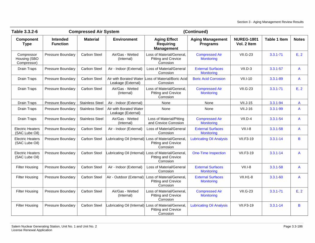
Section 3 - Aging Management Review Results
Salem Nuclear Generating Station, Unit No. 1 and Unit No. 2 Page 3.3-186 License Renewal Application
Table 3.3.2-6 Compressed Air System (Continued)
Component Type
Intended Function
Material Environment Aging Effect Requiring
Management
Aging Management Programs
NUREG-1801 Vol. 2 Item
Table 1 Item Notes
Compressor Housing (SBO Compressor)
Pressure Boundary Carbon Steel Air/Gas - Wetted (Internal)
Loss of Material/General, Pitting and Crevice
Corrosion
Compressed Air Monitoring
VII.G-23 3.3.1-71 E, 2
Drain Traps Pressure Boundary Carbon Steel Air - Indoor (External) Loss of Material/General Corrosion
External Surfaces Monitoring
VII.D-3 3.3.1-57 A
Drain Traps Pressure Boundary Carbon Steel Air with Borated Water Leakage (External)
Loss of Material/Boric Acid Corrosion
Boric Acid Corrosion VII.I-10 3.3.1-89 A
Drain Traps Pressure Boundary Carbon Steel Air/Gas - Wetted (Internal)
Loss of Material/General, Pitting and Crevice
Corrosion
Compressed Air Monitoring
VII.G-23 3.3.1-71 E, 2
Drain Traps Pressure Boundary Stainless Steel Air - Indoor (External) None None VII.J-15 3.3.1-94 A Drain Traps Pressure Boundary Stainless Steel Air with Borated Water
Leakage (External) None None VII.J-16 3.3.1-99 A
Drain Traps Pressure Boundary Stainless Steel Air/Gas - Wetted (Internal)
Loss of Material/Pitting and Crevice Corrosion
Compressed Air Monitoring
VII.D-4 3.3.1-54 A
Electric Heaters (SAC Lube Oil)
Pressure Boundary Carbon Steel Air - Indoor (External) Loss of Material/General Corrosion
External Surfaces Monitoring
VII.I-8 3.3.1-58 A
Electric Heaters (SAC Lube Oil)
Pressure Boundary Carbon Steel Lubricating Oil (Internal) Loss of Material/General, Pitting and Crevice
Corrosion
Lubricating Oil Analysis VII.F3-19 3.3.1-14 B
Electric Heaters (SAC Lube Oil)
Pressure Boundary Carbon Steel Lubricating Oil (Internal) Loss of Material/General, Pitting and Crevice
Corrosion
One-Time Inspection VII.F3-19 3.3.1-14 A
Filter Housing Pressure Boundary Carbon Steel Air - Indoor (External) Loss of Material/General Corrosion
External Surfaces Monitoring
VII.I-8 3.3.1-58 A
Filter Housing Pressure Boundary Carbon Steel Air - Outdoor (External) Loss of Material/General, Pitting and Crevice
Corrosion
External Surfaces Monitoring
VII.H1-8 3.3.1-60 A
Filter Housing Pressure Boundary Carbon Steel Air/Gas - Wetted (Internal)
Loss of Material/General, Pitting and Crevice
Corrosion
Compressed Air Monitoring
VII.G-23 3.3.1-71 E, 2
Filter Housing Pressure Boundary Carbon Steel Lubricating Oil (Internal) Loss of Material/General, Pitting and Crevice
Corrosion
Lubricating Oil Analysis VII.F3-19 3.3.1-14 B

Section 3 - Aging Management Review Results
Salem Nuclear Generating Station, Unit No. 1 and Unit No. 2 Page 3.3-187 License Renewal Application
Table 3.3.2-6 Compressed Air System (Continued)
Component Type
Intended Function
Material Environment Aging Effect Requiring
Management
Aging Management Programs
NUREG-1801 Vol. 2 Item
Table 1 Item Notes
Filter Housing Pressure Boundary Carbon Steel Lubricating Oil (Internal) Loss of Material/General, Pitting and Crevice
Corrosion
One-Time Inspection VII.F3-19 3.3.1-14 A
Flow Element Pressure Boundary Stainless Steel Air - Indoor (External) None None VII.J-15 3.3.1-94 A Flow Element Pressure Boundary Stainless Steel Air/Gas - Wetted
(Internal) Loss of Material/Pitting and Crevice Corrosion
Compressed Air Monitoring
VII.D-4 3.3.1-54 A
Flow Element Structural Support Stainless Steel Air - Indoor (External) None None VII.J-15 3.3.1-94 A Flow Element Structural Support Stainless Steel Air/Gas - Dry (Internal) None Compressed Air
Monitoring VII.J-18 3.3.1-98 E, 1
Heat Exchanger Components
(ECAC Aftercooler)
Evaluated with the Chilled Water
System
Not Applicable Not Applicable Not Applicable Not Applicable 5
Heat Exchanger Components
(ECAC Intercooler)
Evaluated with the Chilled Water
System
Not Applicable Not Applicable Not Applicable Not Applicable 5
Heat Exchanger Components (Penetration
Coolers)
Heat Transfer Stainless Steel Air - Indoor (External) None None VII.J-15 3.3.1-94 C
Heat Exchanger Components (Penetration
Coolers)
Heat Transfer Stainless Steel Air/Gas - Wetted (Internal)
Reduction of Heat Transfer/Fouling
Periodic Inspection H, 6
Heat Exchanger Components (Penetration
Coolers)
Pressure Boundary Stainless Steel Air - Indoor (External) None None VII.J-15 3.3.1-94 C
Heat Exchanger Components (Penetration
Coolers)
Pressure Boundary Stainless Steel Air with Borated Water Leakage (External)
None None VII.J-16 3.3.1-99 C
Heat Exchanger Components (Penetration
Coolers)
Pressure Boundary Stainless Steel Air/Gas - Wetted (Internal)
Loss of Material/Pitting and Crevice Corrosion
Periodic Inspection VII.D-4 3.3.1-54 E, 7

Section 3 - Aging Management Review Results
Salem Nuclear Generating Station, Unit No. 1 and Unit No. 2 Page 3.3-188 License Renewal Application
Table 3.3.2-6 Compressed Air System (Continued)
Component Type
Intended Function
Material Environment Aging Effect Requiring
Management
Aging Management Programs
NUREG-1801 Vol. 2 Item
Table 1 Item Notes
Heat Exchanger Components (SAC
Aftercooler)
Evaluated with the Service Water
System
Not Applicable Not Applicable Not Applicable Not Applicable 8
Heat Exchanger Components (SAC
Intercooler)
Evaluated with the Service Water
System
Not Applicable Not Applicable Not Applicable Not Applicable 8
Heat Exchanger Components (SAC Lube Oil Cooler)
Evaluated with the Service Water
System
Not Applicable Not Applicable Not Applicable Not Applicable 8
Heat Exchanger Components (SBO
Aftercooler)
Heat Transfer Aluminum (Fins) Air - Indoor (External) Reduction of Heat Transfer/Fouling
Periodic Inspection H, 9
Heat Exchanger Components (SBO
Aftercooler)
Heat Transfer Aluminum (Tubes)
Air - Indoor (External) Reduction of Heat Transfer/Fouling
Periodic Inspection H, 9
Heat Exchanger Components (SBO
Aftercooler)
Heat Transfer Aluminum (Tubes)
Air/Gas - Wetted (Internal)
Reduction of Heat Transfer/Fouling
Periodic Inspection H, 9
Heat Exchanger Components (SBO
Aftercooler)
Pressure Boundary Aluminum (Tubes)
Air - Indoor (External) None None V.F-2 3.2.1-50 C
Heat Exchanger Components (SBO
Aftercooler)
Pressure Boundary Aluminum (Tubes)
Air/Gas - Wetted (Internal)
Loss of Material/Pitting and Crevice Corrosion
Periodic Inspection VII.F1-14 3.3.1-27 E, 7
Hoses Pressure Boundary Stainless Steel Air - Indoor (External) None None VII.J-15 3.3.1-94 A Hoses Pressure Boundary Stainless Steel Air with Borated Water
Leakage (External) None None VII.J-16 3.3.1-99 A
Hoses Pressure Boundary Stainless Steel Air/Gas - Dry (Internal) None Compressed Air Monitoring
VII.J-18 3.3.1-98 E, 1
Hoses Pressure Boundary Stainless Steel Air/Gas - Wetted (Internal)
Loss of Material/Pitting and Crevice Corrosion
Compressed Air Monitoring
VII.D-4 3.3.1-54 A
Piping and Fittings Pressure Boundary Carbon Steel Air - Indoor (External) Loss of Material/General Corrosion
External Surfaces Monitoring
VII.D-3 3.3.1-57 A

Section 3 - Aging Management Review Results
Salem Nuclear Generating Station, Unit No. 1 and Unit No. 2 Page 3.3-189 License Renewal Application
Table 3.3.2-6 Compressed Air System (Continued)
Component Type
Intended Function
Material Environment Aging Effect Requiring
Management
Aging Management Programs
NUREG-1801 Vol. 2 Item
Table 1 Item Notes
Piping and Fittings Pressure Boundary Carbon Steel Air - Outdoor (External) Loss of Material/General, Pitting and Crevice
Corrosion
External Surfaces Monitoring
VII.H1-8 3.3.1-60 A
Piping and Fittings Pressure Boundary Carbon Steel Air with Borated Water Leakage (External)
Loss of Material/Boric Acid Corrosion
Boric Acid Corrosion VII.I-10 3.3.1-89 A
Piping and Fittings Pressure Boundary Carbon Steel Air/Gas - Dry (Internal) None Compressed Air Monitoring
VII.J-22 3.3.1-98 E, 1
Piping and Fittings Pressure Boundary Carbon Steel Air/Gas - Wetted (Internal)
Loss of Material/General, Pitting and Crevice
Corrosion
Compressed Air Monitoring
VII.G-23 3.3.1-71 E, 2
Piping and Fittings Pressure Boundary Carbon Steel Soil (External) Loss of Material/General, Pitting, Crevice, and
Microbiologically Influenced Corrosion
Buried Piping Inspection VII.H1-9 3.3.1-19 A
Piping and Fittings Pressure Boundary Stainless Steel Air - Indoor (External) None None VII.J-15 3.3.1-94 A Piping and Fittings Pressure Boundary Stainless Steel Air with Borated Water
Leakage (External) None None VII.J-16 3.3.1-99 A
Piping and Fittings Pressure Boundary Stainless Steel Air/Gas - Dry (Internal) None Compressed Air Monitoring
VII.J-18 3.3.1-98 E, 1
Piping and Fittings Pressure Boundary Stainless Steel Air/Gas - Wetted (Internal)
Loss of Material/Pitting and Crevice Corrosion
Compressed Air Monitoring
VII.D-4 3.3.1-54 A
Piping and Fittings Structural Support Carbon Steel Air - Indoor (External) Loss of Material/General Corrosion
External Surfaces Monitoring
VII.D-3 3.3.1-57 A
Piping and Fittings Structural Support Carbon Steel Air with Borated Water Leakage (External)
Loss of Material/Boric Acid Corrosion
Boric Acid Corrosion VII.I-10 3.3.1-89 A
Piping and Fittings Structural Support Carbon Steel Air/Gas - Dry (Internal) None Compressed Air Monitoring
VII.J-22 3.3.1-98 E, 1
Piping and Fittings Structural Support Carbon Steel Air/Gas - Wetted (Internal)
Loss of Material/General, Pitting and Crevice
Corrosion
Compressed Air Monitoring
VII.G-23 3.3.1-71 E, 2
Piping and Fittings Structural Support Stainless Steel Air - Indoor (External) None None VII.J-15 3.3.1-94 A Piping and Fittings Structural Support Stainless Steel Air with Borated Water
Leakage (External) None None VII.J-16 3.3.1-99 A
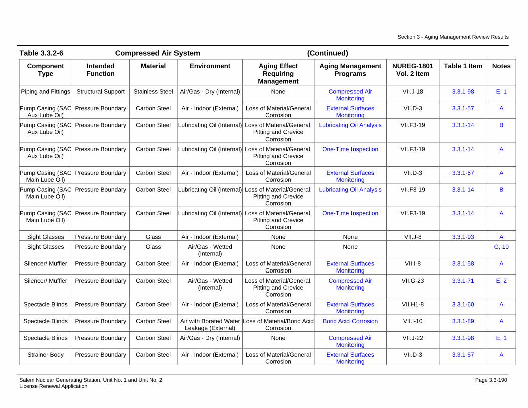
Section 3 - Aging Management Review Results
Salem Nuclear Generating Station, Unit No. 1 and Unit No. 2 Page 3.3-190 License Renewal Application
Table 3.3.2-6 Compressed Air System (Continued)
Component Type
Intended Function
Material Environment Aging Effect Requiring
Management
Aging Management Programs
NUREG-1801 Vol. 2 Item
Table 1 Item Notes
Piping and Fittings Structural Support Stainless Steel Air/Gas - Dry (Internal) None Compressed Air Monitoring
VII.J-18 3.3.1-98 E, 1
Pump Casing (SAC Aux Lube Oil)
Pressure Boundary Carbon Steel Air - Indoor (External) Loss of Material/General Corrosion
External Surfaces Monitoring
VII.D-3 3.3.1-57 A
Pump Casing (SAC Aux Lube Oil)
Pressure Boundary Carbon Steel Lubricating Oil (Internal) Loss of Material/General, Pitting and Crevice
Corrosion
Lubricating Oil Analysis VII.F3-19 3.3.1-14 B
Pump Casing (SAC Aux Lube Oil)
Pressure Boundary Carbon Steel Lubricating Oil (Internal) Loss of Material/General, Pitting and Crevice
Corrosion
One-Time Inspection VII.F3-19 3.3.1-14 A
Pump Casing (SAC Main Lube Oil)
Pressure Boundary Carbon Steel Air - Indoor (External) Loss of Material/General Corrosion
External Surfaces Monitoring
VII.D-3 3.3.1-57 A
Pump Casing (SAC Main Lube Oil)
Pressure Boundary Carbon Steel Lubricating Oil (Internal) Loss of Material/General, Pitting and Crevice
Corrosion
Lubricating Oil Analysis VII.F3-19 3.3.1-14 B
Pump Casing (SAC Main Lube Oil)
Pressure Boundary Carbon Steel Lubricating Oil (Internal) Loss of Material/General, Pitting and Crevice
Corrosion
One-Time Inspection VII.F3-19 3.3.1-14 A
Sight Glasses Pressure Boundary Glass Air - Indoor (External) None None VII.J-8 3.3.1-93 A Sight Glasses Pressure Boundary Glass Air/Gas - Wetted
(Internal) None None G, 10
Silencer/ Muffler Pressure Boundary Carbon Steel Air - Indoor (External) Loss of Material/General Corrosion
External Surfaces Monitoring
VII.I-8 3.3.1-58 A
Silencer/ Muffler Pressure Boundary Carbon Steel Air/Gas - Wetted (Internal)
Loss of Material/General, Pitting and Crevice
Corrosion
Compressed Air Monitoring
VII.G-23 3.3.1-71 E, 2
Spectacle Blinds Pressure Boundary Carbon Steel Air - Indoor (External) Loss of Material/General Corrosion
External Surfaces Monitoring
VII.H1-8 3.3.1-60 A
Spectacle Blinds Pressure Boundary Carbon Steel Air with Borated Water Leakage (External)
Loss of Material/Boric Acid Corrosion
Boric Acid Corrosion VII.I-10 3.3.1-89 A
Spectacle Blinds Pressure Boundary Carbon Steel Air/Gas - Dry (Internal) None Compressed Air Monitoring
VII.J-22 3.3.1-98 E, 1
Strainer Body Pressure Boundary Carbon Steel Air - Indoor (External) Loss of Material/General Corrosion
External Surfaces Monitoring
VII.D-3 3.3.1-57 A

Section 3 - Aging Management Review Results
Salem Nuclear Generating Station, Unit No. 1 and Unit No. 2 Page 3.3-191 License Renewal Application
Table 3.3.2-6 Compressed Air System (Continued)
Component Type
Intended Function
Material Environment Aging Effect Requiring
Management
Aging Management Programs
NUREG-1801 Vol. 2 Item
Table 1 Item Notes
Strainer Body Pressure Boundary Carbon Steel Air with Borated Water Leakage (External)
Loss of Material/Boric Acid Corrosion
Boric Acid Corrosion VII.I-10 3.3.1-89 A
Strainer Body Pressure Boundary Carbon Steel Air/Gas - Dry (Internal) None Compressed Air Monitoring
VII.J-22 3.3.1-98 E, 1
Strainer Body Pressure Boundary Carbon Steel Air/Gas - Wetted (Internal)
Loss of Material/General, Pitting and Crevice
Corrosion
Compressed Air Monitoring
VII.G-23 3.3.1-71 E, 2
Strainer Body Pressure Boundary Stainless Steel Air - Indoor (External) None None VII.J-15 3.3.1-94 A Strainer Body Pressure Boundary Stainless Steel Air with Borated Water
Leakage (External) None None VII.J-16 3.3.1-99 A
Strainer Body Pressure Boundary Stainless Steel Air/Gas - Wetted (Internal)
Loss of Material/Pitting and Crevice Corrosion
Compressed Air Monitoring
VII.D-4 3.3.1-54 A
Tanks (SAC Lube Oil Reservoir)
Pressure Boundary Carbon Steel Air - Indoor (External) Loss of Material/General Corrosion
External Surfaces Monitoring
VII.I-8 3.3.1-58 A
Tanks (SAC Lube Oil Reservoir)
Pressure Boundary Carbon Steel Lubricating Oil (Internal) Loss of Material/General, Pitting and Crevice
Corrosion
Lubricating Oil Analysis VII.F3-19 3.3.1-14 D
Tanks (SAC Lube Oil Reservoir)
Pressure Boundary Carbon Steel Lubricating Oil (Internal) Loss of Material/General, Pitting and Crevice
Corrosion
One-Time Inspection VII.F3-19 3.3.1-14 C
Tanks (SAC Moisture
Separator)
Pressure Boundary Carbon Steel Air - Indoor (External) Loss of Material/General Corrosion
External Surfaces Monitoring
VII.I-8 3.3.1-58 A
Tanks (SAC Moisture
Separator)
Pressure Boundary Carbon Steel Air/Gas - Wetted (Internal)
Loss of Material/General, Pitting and Crevice
Corrosion
Compressed Air Monitoring
VII.G-23 3.3.1-71 E, 2
Tanks (SBO Aftercooler Moisture
Separator, ECAC Aftercooler Moisture
Seperator)
Pressure Boundary Carbon Steel Air - Indoor (External) Loss of Material/General Corrosion
External Surfaces Monitoring
VII.I-8 3.3.1-58 A

Section 3 - Aging Management Review Results
Salem Nuclear Generating Station, Unit No. 1 and Unit No. 2 Page 3.3-192 License Renewal Application
Table 3.3.2-6 Compressed Air System (Continued)
Component Type
Intended Function
Material Environment Aging Effect Requiring
Management
Aging Management Programs
NUREG-1801 Vol. 2 Item
Table 1 Item Notes
Tanks (SBO Aftercooler Moisture
Separator, ECAC Aftercooler Moisture
Seperator)
Pressure Boundary Carbon Steel Air/Gas - Wetted (Internal)
Loss of Material/General, Pitting and Crevice
Corrosion
Compressed Air Monitoring
VII.G-23 3.3.1-71 E, 2
Tanks (SBO Dryer, ECAC Dryer)
Pressure Boundary Carbon Steel Air - Indoor (External) Loss of Material/General Corrosion
External Surfaces Monitoring
VII.I-8 3.3.1-58 A
Tanks (SBO Dryer, ECAC Dryer)
Pressure Boundary Carbon Steel Air/Gas - Wetted (Internal)
Loss of Material/General, Pitting and Crevice
Corrosion
Compressed Air Monitoring
VII.G-23 3.3.1-71 E, 2
Tanks (Station Air Reciever, Control
Air Reciever)
Pressure Boundary Carbon Steel Air - Indoor (External) Loss of Material/General Corrosion
External Surfaces Monitoring
VII.I-8 3.3.1-58 A
Tanks (Station Air Reciever, Control
Air Reciever)
Pressure Boundary Carbon Steel Air/Gas - Dry (Internal) None Compressed Air Monitoring
VII.J-22 3.3.1-98 E, 1
Thermowell Pressure Boundary Stainless Steel Air - Indoor (External) None None VII.J-15 3.3.1-94 A Thermowell Pressure Boundary Stainless Steel Air/Gas - Wetted
(Internal) Loss of Material/Pitting and Crevice Corrosion
Compressed Air Monitoring
VII.D-4 3.3.1-54 A
Valve Body Pressure Boundary Carbon Steel Air - Indoor (External) Loss of Material/General Corrosion
External Surfaces Monitoring
VII.D-3 3.3.1-57 A
Valve Body Pressure Boundary Carbon Steel Air - Outdoor (External) Loss of Material/General, Pitting and Crevice
Corrosion
External Surfaces Monitoring
VII.H1-8 3.3.1-60 A
Valve Body Pressure Boundary Carbon Steel Air with Borated Water Leakage (External)
Loss of Material/Boric Acid Corrosion
Boric Acid Corrosion VII.I-10 3.3.1-89 A
Valve Body Pressure Boundary Carbon Steel Air/Gas - Dry (Internal) None Compressed Air Monitoring
VII.J-22 3.3.1-98 E, 1
Valve Body Pressure Boundary Carbon Steel Air/Gas - Wetted (Internal)
Loss of Material/General, Pitting and Crevice
Corrosion
Compressed Air Monitoring
VII.G-23 3.3.1-71 E, 2
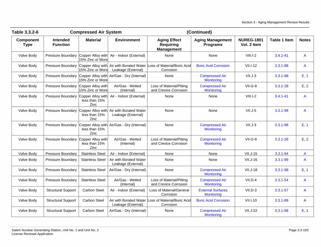
Section 3 - Aging Management Review Results
Salem Nuclear Generating Station, Unit No. 1 and Unit No. 2 Page 3.3-193 License Renewal Application
Table 3.3.2-6 Compressed Air System (Continued)
Component Type
Intended Function
Material Environment Aging Effect Requiring
Management
Aging Management Programs
NUREG-1801 Vol. 2 Item
Table 1 Item Notes
Valve Body Pressure Boundary Copper Alloy with 15% Zinc or More
Air - Indoor (External) None None VIII.I-2 3.4.1-41 A
Valve Body Pressure Boundary Copper Alloy with 15% Zinc or More
Air with Borated Water Leakage (External)
Loss of Material/Boric Acid Corrosion
Boric Acid Corrosion VII.I-12 3.3.1-88 A
Valve Body Pressure Boundary Copper Alloy with 15% Zinc or More
Air/Gas - Dry (Internal) None Compressed Air Monitoring
VII.J-3 3.3.1-98 E, 1
Valve Body Pressure Boundary Copper Alloy with 15% Zinc or More
Air/Gas - Wetted (Internal)
Loss of Material/Pitting and Crevice Corrosion
Compressed Air Monitoring
VII.G-9 3.3.1-28 E, 2
Valve Body Pressure Boundary Copper Alloy with less than 15%
Zinc
Air - Indoor (External) None None VIII.I-2 3.4.1-41 A
Valve Body Pressure Boundary Copper Alloy with less than 15%
Zinc
Air with Borated Water Leakage (External)
None None VII.J-5 3.3.1-99 A
Valve Body Pressure Boundary Copper Alloy with less than 15%
Zinc
Air/Gas - Dry (Internal) None Compressed Air Monitoring
VII.J-3 3.3.1-98 E, 1
Valve Body Pressure Boundary Copper Alloy with less than 15%
Zinc
Air/Gas - Wetted (Internal)
Loss of Material/Pitting and Crevice Corrosion
Compressed Air Monitoring
VII.G-9 3.3.1-28 E, 2
Valve Body Pressure Boundary Stainless Steel Air - Indoor (External) None None VII.J-15 3.3.1-94 A Valve Body Pressure Boundary Stainless Steel Air with Borated Water
Leakage (External) None None VII.J-16 3.3.1-99 A
Valve Body Pressure Boundary Stainless Steel Air/Gas - Dry (Internal) None Compressed Air Monitoring
VII.J-18 3.3.1-98 E, 1
Valve Body Pressure Boundary Stainless Steel Air/Gas - Wetted (Internal)
Loss of Material/Pitting and Crevice Corrosion
Compressed Air Monitoring
VII.D-4 3.3.1-54 A
Valve Body Structural Support Carbon Steel Air - Indoor (External) Loss of Material/General Corrosion
External Surfaces Monitoring
VII.D-3 3.3.1-57 A
Valve Body Structural Support Carbon Steel Air with Borated Water Leakage (External)
Loss of Material/Boric Acid Corrosion
Boric Acid Corrosion VII.I-10 3.3.1-89 A
Valve Body Structural Support Carbon Steel Air/Gas - Dry (Internal) None Compressed Air Monitoring
VII.J-22 3.3.1-98 E, 1
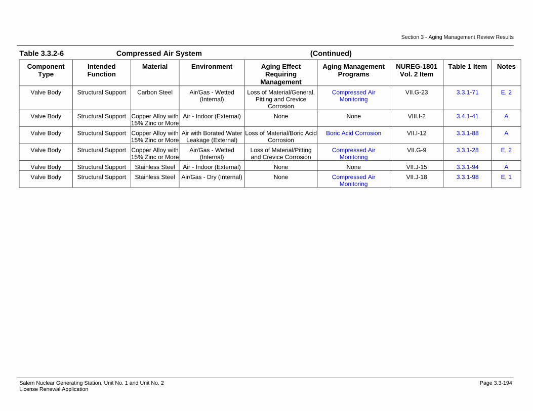
Section 3 - Aging Management Review Results
Salem Nuclear Generating Station, Unit No. 1 and Unit No. 2 Page 3.3-194 License Renewal Application
Table 3.3.2-6 Compressed Air System (Continued)
Component Type
Intended Function
Material Environment Aging Effect Requiring
Management
Aging Management Programs
NUREG-1801 Vol. 2 Item
Table 1 Item Notes
Valve Body Structural Support Carbon Steel Air/Gas - Wetted (Internal)
Loss of Material/General, Pitting and Crevice
Corrosion
Compressed Air Monitoring
VII.G-23 3.3.1-71 E, 2
Valve Body Structural Support Copper Alloy with 15% Zinc or More
Air - Indoor (External) None None VIII.I-2 3.4.1-41 A
Valve Body Structural Support Copper Alloy with 15% Zinc or More
Air with Borated Water Leakage (External)
Loss of Material/Boric Acid Corrosion
Boric Acid Corrosion VII.I-12 3.3.1-88 A
Valve Body Structural Support Copper Alloy with 15% Zinc or More
Air/Gas - Wetted (Internal)
Loss of Material/Pitting and Crevice Corrosion
Compressed Air Monitoring
VII.G-9 3.3.1-28 E, 2
Valve Body Structural Support Stainless Steel Air - Indoor (External) None None VII.J-15 3.3.1-94 A Valve Body Structural Support Stainless Steel Air/Gas - Dry (Internal) None Compressed Air
Monitoring VII.J-18 3.3.1-98 E, 1

Section 3 - Aging Management Review Results
Salem Nuclear Generating Station, Unit No. 1 and Unit No. 2 Page 3.3-195 License Renewal Application
Notes Definition of Note
A Consistent with NUREG-1801 item for component, material, environment, and aging effect. AMP is consistent with NUREG-1801 AMP.
B Consistent with NUREG-1801 item for component, material, environment, and aging effect. AMP takes some exceptions to NUREG-1801 AMP.
C Component is different, but consistent with NUREG-1801 item for material, environment, and aging effect. AMP is consistent with NUREG-1801 AMP.
D Component is different, but consistent with NUREG-1801 item for material, environment, and aging effect. AMP takes some exceptions to NUREG-1801 AMP.
E Consistent with NUREG-1801 item for material, environment and aging effect, but a different aging management program is credited or NUREG-1801 identifies a plant-specific aging management program.
F Material not in NUREG-1801 for this component.
G Environment not in NUREG-1801 for this component and material.
H Aging effect not in NUREG-1801 for this component, material and environment combination.
I Aging effect in NUREG-1801 for this component, material and environment combination is not applicable.
J Neither the component nor the material and environment combination is evaluated in NUREG-1801.
Plant Specific Notes:
1. The Compressed Air Monitoring program is substituted to manage the aging effect(s) applicable to this component type, material, and environment combination. The Compressed Air Monitoring program is applied to confirm the internal environment remains sufficiently dry to preclude aging effects.
2. The Compressed Air Monitoring program is substituted to manage the aging effect(s) applicable to this component type, material, and environment combination.
3. The aging effects for closure bolting in a soil environment include loss of material and loss of preload. External inspections of buried bolting will occur in accordance with the frequency outlined in the Buried Piping Inspection program.
4. The Bolting Integrity program is substituted to manage the aging effect(s) applicable to this component type, material, and environment combination.
5. This component is evaluated with the Chilled Water System.
6. The Periodic Inspection program is substituted to manage the aging effect(s) applicable to this component type, material, and environment combination. The Periodic Inspection program is applied to confirm the internal environment remains sufficiently dry to preclude aging effects.

Section 3 - Aging Management Review Results
Salem Nuclear Generating Station, Unit No. 1 and Unit No. 2 Page 3.3-196 License Renewal Application
7. The Periodic Inspection program is substituted to manage the aging effect(s) applicable to this component type, material, and environment combination.
8. This component is evaluated with the Service Water System.
9. The aging effect/mechanism of reduction of heat transfer due to fouling is not in NUREG-1801 for this component, material, and environment, however, it is applicable to this combination. The Periodic Inspection program is used to manage the aging effects for this component, material, and environment combination.
10. This environment is not in NUREG-1801 for this component and material. There are no aging effects for glass in an air/gas-wetted environment, based on other NUREG-1801 items for glass, such as VII.J-12 for glass in a treated borated water environment.
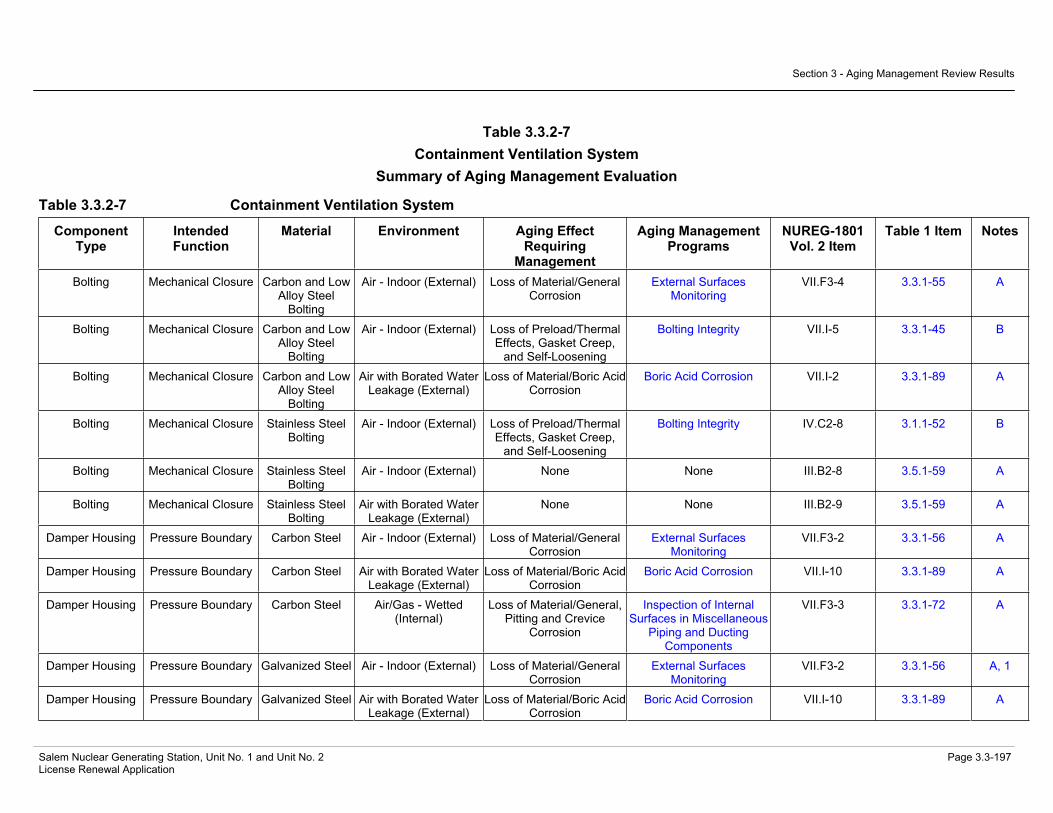
Section 3 - Aging Management Review Results
Salem Nuclear Generating Station, Unit No. 1 and Unit No. 2 Page 3.3-197 License Renewal Application
Table 3.3.2-7 Containment Ventilation System
Summary of Aging Management Evaluation
Table 3.3.2-7 Containment Ventilation System
Component Type
Intended Function
Material Environment Aging Effect Requiring
Management
Aging Management Programs
NUREG-1801 Vol. 2 Item
Table 1 Item Notes
Bolting Mechanical Closure Carbon and Low Alloy Steel
Bolting
Air - Indoor (External) Loss of Material/General Corrosion
External Surfaces Monitoring
VII.F3-4 3.3.1-55 A
Bolting Mechanical Closure Carbon and Low Alloy Steel
Bolting
Air - Indoor (External) Loss of Preload/Thermal Effects, Gasket Creep,
and Self-Loosening
Bolting Integrity VII.I-5 3.3.1-45 B
Bolting Mechanical Closure Carbon and Low Alloy Steel
Bolting
Air with Borated Water Leakage (External)
Loss of Material/Boric Acid Corrosion
Boric Acid Corrosion VII.I-2 3.3.1-89 A
Bolting Mechanical Closure Stainless Steel Bolting
Air - Indoor (External) Loss of Preload/Thermal Effects, Gasket Creep,
and Self-Loosening
Bolting Integrity IV.C2-8 3.1.1-52 B
Bolting Mechanical Closure Stainless Steel Bolting
Air - Indoor (External) None None III.B2-8 3.5.1-59 A
Bolting Mechanical Closure Stainless Steel Bolting
Air with Borated Water Leakage (External)
None None III.B2-9 3.5.1-59 A
Damper Housing Pressure Boundary Carbon Steel Air - Indoor (External) Loss of Material/General Corrosion
External Surfaces Monitoring
VII.F3-2 3.3.1-56 A
Damper Housing Pressure Boundary Carbon Steel Air with Borated Water Leakage (External)
Loss of Material/Boric Acid Corrosion
Boric Acid Corrosion VII.I-10 3.3.1-89 A
Damper Housing Pressure Boundary Carbon Steel Air/Gas - Wetted (Internal)
Loss of Material/General, Pitting and Crevice
Corrosion
Inspection of Internal Surfaces in Miscellaneous
Piping and Ducting Components
VII.F3-3 3.3.1-72 A
Damper Housing Pressure Boundary Galvanized Steel Air - Indoor (External) Loss of Material/General Corrosion
External Surfaces Monitoring
VII.F3-2 3.3.1-56 A, 1
Damper Housing Pressure Boundary Galvanized Steel Air with Borated Water Leakage (External)
Loss of Material/Boric Acid Corrosion
Boric Acid Corrosion VII.I-10 3.3.1-89 A

Section 3 - Aging Management Review Results
Salem Nuclear Generating Station, Unit No. 1 and Unit No. 2 Page 3.3-198 License Renewal Application
Table 3.3.2-7 Containment Ventilation System (Continued)
Component Type
Intended Function
Material Environment Aging Effect Requiring
Management
Aging Management Programs
NUREG-1801 Vol. 2 Item
Table 1 Item Notes
Damper Housing Pressure Boundary Galvanized Steel Air/Gas - Wetted (Internal)
Loss of Material/General, Pitting and Crevice
Corrosion
Inspection of Internal Surfaces in Miscellaneous
Piping and Ducting Components
VII.F3-3 3.3.1-72 A
Door Seals Pressure Boundary Elastomer Air - Indoor (External) Hardening and Loss of Strength/Elastomer
Degradation
Periodic Inspection VII.F3-7 3.3.1-11 E, 2
Door Seals Pressure Boundary Elastomer Air with Borated Water Leakage (External)
None None G, 3
Door Seals Pressure Boundary Elastomer Air/Gas - Wetted (Internal)
Hardening and Loss of Strength/Elastomer
Degradation
Periodic Inspection G
Ducting and Components
Pressure Boundary Carbon Steel Air - Indoor (External) Loss of Material/General Corrosion
External Surfaces Monitoring
VII.F3-2 3.3.1-56 A
Ducting and Components
Pressure Boundary Carbon Steel Air with Borated Water Leakage (External)
Loss of Material/Boric Acid Corrosion
Boric Acid Corrosion VII.I-10 3.3.1-89 A
Ducting and Components
Pressure Boundary Carbon Steel Air/Gas - Wetted (Internal)
Loss of Material/General, Pitting and Crevice
Corrosion
Inspection of Internal Surfaces in Miscellaneous
Piping and Ducting Components
VII.F3-3 3.3.1-72 A
Ducting and Components
Pressure Boundary Galvanized Steel Air - Indoor (External) Loss of Material/General Corrosion
External Surfaces Monitoring
VII.F3-2 3.3.1-56 A, 1
Ducting and Components
Pressure Boundary Galvanized Steel Air with Borated Water Leakage (External)
Loss of Material/Boric Acid Corrosion
Boric Acid Corrosion VII.I-10 3.3.1-89 A
Ducting and Components
Pressure Boundary Galvanized Steel Air/Gas - Wetted (Internal)
Loss of Material/General, Pitting and Crevice
Corrosion
Inspection of Internal Surfaces in Miscellaneous
Piping and Ducting Components
VII.F3-3 3.3.1-72 A
Fan Housing Pressure Boundary Carbon Steel Air - Indoor (External) Loss of Material/General Corrosion
External Surfaces Monitoring
VII.F3-2 3.3.1-56 A
Fan Housing Pressure Boundary Carbon Steel Air with Borated Water Leakage (External)
Loss of Material/Boric Acid Corrosion
Boric Acid Corrosion VII.I-10 3.3.1-89 A

Section 3 - Aging Management Review Results
Salem Nuclear Generating Station, Unit No. 1 and Unit No. 2 Page 3.3-199 License Renewal Application
Table 3.3.2-7 Containment Ventilation System (Continued)
Component Type
Intended Function
Material Environment Aging Effect Requiring
Management
Aging Management Programs
NUREG-1801 Vol. 2 Item
Table 1 Item Notes
Fan Housing Pressure Boundary Carbon Steel Air/Gas - Wetted (Internal)
Loss of Material/General, Pitting and Crevice
Corrosion
Inspection of Internal Surfaces in Miscellaneous
Piping and Ducting Components
VII.F3-3 3.3.1-72 A
Filter Housing Pressure Boundary Carbon Steel Air - Indoor (External) Loss of Material/General Corrosion
External Surfaces Monitoring
VII.F3-2 3.3.1-56 A
Filter Housing Pressure Boundary Carbon Steel Air with Borated Water Leakage (External)
Loss of Material/Boric Acid Corrosion
Boric Acid Corrosion VII.I-10 3.3.1-89 A
Filter Housing Pressure Boundary Carbon Steel Air/Gas - Wetted (Internal)
Loss of Material/General, Pitting and Crevice
Corrosion
Inspection of Internal Surfaces in Miscellaneous
Piping and Ducting Components
VII.F3-3 3.3.1-72 A
Flexible Connection
Pressure Boundary Elastomer Air - Indoor (External) Hardening and Loss of Strength/Elastomer
Degradation
Periodic Inspection VII.F3-7 3.3.1-11 E, 2
Flexible Connection
Pressure Boundary Elastomer Air with Borated Water Leakage (External)
None None G, 3
Flexible Connection
Pressure Boundary Elastomer Air/Gas - Wetted (Internal)
Hardening and Loss of Strength/Elastomer
Degradation
Periodic Inspection G
Heat Exchanger Components (Fan Coil Motor Cooling
HX)
Evaluated with the Service Water
System
Not Applicable Not Applicable Not Applicable Not Applicable 4
Heat Exchanger Components (Fan Coil Unit Coolers)
Evaluated with the Service Water
System
Not Applicable Not Applicable Not Applicable Not Applicable 4
Piping and Fittings Pressure Boundary Carbon Steel Air - Indoor (External) Loss of Material/General Corrosion
External Surfaces Monitoring
VII.D-3 3.3.1-57 A
Piping and Fittings Pressure Boundary Carbon Steel Air with Borated Water Leakage (External)
Loss of Material/Boric Acid Corrosion
Boric Acid Corrosion VII.I-10 3.3.1-89 A
Piping and Fittings Pressure Boundary Carbon Steel Air/Gas - Wetted (Internal)
Loss of Material/General, Pitting and Crevice
Corrosion
Inspection of Internal Surfaces in Miscellaneous
Piping and Ducting Components
VII.G-23 3.3.1-71 A
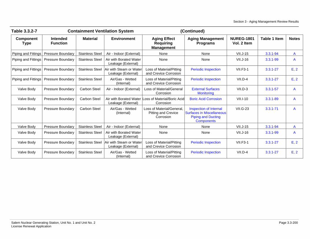
Section 3 - Aging Management Review Results
Salem Nuclear Generating Station, Unit No. 1 and Unit No. 2 Page 3.3-200 License Renewal Application
Table 3.3.2-7 Containment Ventilation System (Continued)
Component Type
Intended Function
Material Environment Aging Effect Requiring
Management
Aging Management Programs
NUREG-1801 Vol. 2 Item
Table 1 Item Notes
Piping and Fittings Pressure Boundary Stainless Steel Air - Indoor (External) None None VII.J-15 3.3.1-94 A Piping and Fittings Pressure Boundary Stainless Steel Air with Borated Water
Leakage (External) None None VII.J-16 3.3.1-99 A
Piping and Fittings Pressure Boundary Stainless Steel Air with Steam or Water Leakage (External)
Loss of Material/Pitting and Crevice Corrosion
Periodic Inspection VII.F3-1 3.3.1-27 E, 2
Piping and Fittings Pressure Boundary Stainless Steel Air/Gas - Wetted (Internal)
Loss of Material/Pitting and Crevice Corrosion
Periodic Inspection VII.D-4 3.3.1-27 E, 2
Valve Body Pressure Boundary Carbon Steel Air - Indoor (External) Loss of Material/General Corrosion
External Surfaces Monitoring
VII.D-3 3.3.1-57 A
Valve Body Pressure Boundary Carbon Steel Air with Borated Water Leakage (External)
Loss of Material/Boric Acid Corrosion
Boric Acid Corrosion VII.I-10 3.3.1-89 A
Valve Body Pressure Boundary Carbon Steel Air/Gas - Wetted (Internal)
Loss of Material/General, Pitting and Crevice
Corrosion
Inspection of Internal Surfaces in Miscellaneous
Piping and Ducting Components
VII.G-23 3.3.1-71 A
Valve Body Pressure Boundary Stainless Steel Air - Indoor (External) None None VII.J-15 3.3.1-94 A Valve Body Pressure Boundary Stainless Steel Air with Borated Water
Leakage (External) None None VII.J-16 3.3.1-99 A
Valve Body Pressure Boundary Stainless Steel Air with Steam or Water Leakage (External)
Loss of Material/Pitting and Crevice Corrosion
Periodic Inspection VII.F3-1 3.3.1-27 E, 2
Valve Body Pressure Boundary Stainless Steel Air/Gas - Wetted (Internal)
Loss of Material/Pitting and Crevice Corrosion
Periodic Inspection VII.D-4 3.3.1-27 E, 2

Section 3 - Aging Management Review Results
Salem Nuclear Generating Station, Unit No. 1 and Unit No. 2 Page 3.3-201 License Renewal Application
Notes Definition of Note
A Consistent with NUREG-1801 item for component, material, environment, and aging effect. AMP is consistent with NUREG-1801 AMP.
B Consistent with NUREG-1801 item for component, material, environment, and aging effect. AMP takes some exceptions to NUREG-1801 AMP.
C Component is different, but consistent with NUREG-1801 item for material, environment, and aging effect. AMP is consistent with NUREG-1801 AMP.
D Component is different, but consistent with NUREG-1801 item for material, environment, and aging effect. AMP takes some exceptions to NUREG-1801 AMP.
E Consistent with NUREG-1801 item for material, environment and aging effect, but a different aging management program is credited or NUREG-1801 identifies a plant-specific aging management program.
F Material not in NUREG-1801 for this component.
G Environment not in NUREG-1801 for this component and material.
H Aging effect not in NUREG-1801 for this component, material and environment combination.
I Aging effect in NUREG-1801 for this component, material and environment combination is not applicable.
J Neither the component nor the material and environment combination is evaluated in NUREG-1801.
Plant Specific Notes:
1. Loss of material due to general corrosion on the external surface of this component type has occurred at Salem based on site-specific operating experience reviews.
2. NUREG-1801 specifies a plant-specific program. The Periodic Inspection program is used to manage the aging effect(s) applicable to this component type, material, and environment combination.
3. This environment is not in NUREG-1801 for this component and material. The elastomer material located indoors and subject to an air with borated water leakage environment is not subject to aging effects beyond those experienced in an air-indoor uncontrolled environment that includes hardening and loss of strength/elastomer degradation. These aging effects are already accounted for and are managed by the Periodic Inspection Program.
4. Both the fan coil motor cooling heat exchanger and the fan coil unit coolers are evaluated with the Service Water System.

Section 3 - Aging Management Review Results
Salem Nuclear Generating Station, Unit No. 1 and Unit No. 2 Page 3.3-202 License Renewal Application
Table 3.3.2-8 Control Area Ventilation System
Summary of Aging Management Evaluation
Table 3.3.2-8 Control Area Ventilation System
Component Type
Intended Function
Material Environment Aging Effect Requiring
Management
Aging Management Programs
NUREG-1801 Vol. 2 Item
Table 1 Item Notes
Bird Screen Filter Aluminum Air - Outdoor (External) Loss of Material/Pitting and Crevice Corrosion
Periodic Inspection III.B4-7 3.5.1-50 E, 1
Bird Screen Filter Galvanized Steel Air - Outdoor (External) Loss of Material/General, Pitting and Crevice
Corrosion
External Surfaces Monitoring
VII.H1-8 3.3.1-60 C
Bird Screen Filter Stainless Steel Air - Outdoor (External) Loss of Material/Pitting and Crevice Corrosion
Periodic Inspection III.B4-7 3.5.1-50 E, 1
Bolting Mechanical Closure Carbon and Low Alloy Steel
Bolting
Air - Indoor (External) Loss of Material/General Corrosion
External Surfaces Monitoring
VII.F1-4 3.3.1-55 A
Bolting Mechanical Closure Copper Alloy Bolting with less than 15% Zinc
Air - Indoor (External) None None VIII.I-2 3.4.1-41 C
Bolting Mechanical Closure Stainless Steel Bolting
Air - Indoor (External) None None III.B2-8 3.5.1-59 A
Bolting Mechanical Closure Stainless Steel Bolting
Air - Outdoor (External) Loss of Material/Pitting and Crevice Corrosion
Periodic Inspection III.B2-7 3.5.1-50 E, 1
Damper Housing Pressure Boundary Galvanized Steel Air - Indoor (External) None None VII.J-6 3.3.1-92 C Damper Housing Pressure Boundary Galvanized Steel Air/Gas - Wetted
(Internal) Loss of Material/General,
Pitting and Crevice Corrosion
Inspection of Internal Surfaces in Miscellaneous
Piping and Ducting Components
VII.F1-3 3.3.1-72 A, 2
Door Seals Pressure Boundary Elastomer Air - Indoor (External) Hardening and Loss of Strength/Elastomer
Degradation
Periodic Inspection VII.F1-7 3.3.1-11 E, 3
Door Seals Pressure Boundary Elastomer Air/Gas - Wetted (Internal)
Hardening and Loss of Strength/Elastomer
Degradation
Periodic Inspection G

Section 3 - Aging Management Review Results
Salem Nuclear Generating Station, Unit No. 1 and Unit No. 2 Page 3.3-203 License Renewal Application
Table 3.3.2-8 Control Area Ventilation System (Continued)
Component Type
Intended Function
Material Environment Aging Effect Requiring
Management
Aging Management Programs
NUREG-1801 Vol. 2 Item
Table 1 Item Notes
Ducting and Components
Pressure Boundary Galvanized Steel Air - Indoor (External) None None VII.J-6 3.3.1-92 C
Ducting and Components
Pressure Boundary Galvanized Steel Air - Outdoor (External) Loss of Material/General, Pitting and Crevice
Corrosion
External Surfaces Monitoring
VII.H1-8 3.3.1-60 C
Ducting and Components
Pressure Boundary Galvanized Steel Air/Gas - Wetted (Internal)
Loss of Material/General, Pitting and Crevice
Corrosion
Inspection of Internal Surfaces in Miscellaneous
Piping and Ducting Components
VII.F1-3 3.3.1-72 A, 2
Fan Housing Pressure Boundary Carbon Steel Air - Indoor (External) Loss of Material/General Corrosion
External Surfaces Monitoring
VII.F1-2 3.3.1-56 A
Fan Housing Pressure Boundary Carbon Steel Air/Gas - Wetted (Internal)
Loss of Material/General, Pitting and Crevice
Corrosion
Inspection of Internal Surfaces in Miscellaneous
Piping and Ducting Components
VII.F1-3 3.3.1-72 A, 2
Filter Housing Pressure Boundary Carbon Steel Air - Indoor (External) Loss of Material/General Corrosion
External Surfaces Monitoring
VII.F1-2 3.3.1-56 A
Filter Housing Pressure Boundary Carbon Steel Air/Gas - Wetted (Internal)
Loss of Material/General, Pitting and Crevice
Corrosion
Inspection of Internal Surfaces in Miscellaneous
Piping and Ducting Components
VII.F1-3 3.3.1-72 A, 2
Filter Housing Pressure Boundary Glass (Windows) Air - Indoor (External) None None VII.J-8 3.3.1-93 A Filter Housing Pressure Boundary Glass (Windows) Air/Gas - Wetted
(Internal) None None G, 4
Flexible Connection
Pressure Boundary Elastomer Air - Indoor (External) Hardening and Loss of Strength/Elastomer
Degradation
Periodic Inspection VII.F1-7 3.3.1-11 E, 3
Flexible Connection
Pressure Boundary Elastomer Air/Gas - Wetted (Internal)
Hardening and Loss of Strength/Elastomer
Degradation
Periodic Inspection G
Heat Exchanger Components
(CAAC Heating Coils)
Evaluated with the Heating Water and
Heating Steam System
Not Applicable Not Applicable Not Applicable Not Applicable 6

Section 3 - Aging Management Review Results
Salem Nuclear Generating Station, Unit No. 1 and Unit No. 2 Page 3.3-204 License Renewal Application
Table 3.3.2-8 Control Area Ventilation System (Continued)
Component Type
Intended Function
Material Environment Aging Effect Requiring
Management
Aging Management Programs
NUREG-1801 Vol. 2 Item
Table 1 Item Notes
Heat Exchanger Components (CAAC Unit
Cooling Coils)
Evaluated with the Chilled Water
System
Not Applicable Not Applicable Not Applicable Not Applicable 5
Heat Exchanger Components (CREAC Unit Cooling Coils)
Evaluated with the Chilled Water
System
Not Applicable Not Applicable Not Applicable Not Applicable 5
Louver (Discharge Louver Penthouse)
Pressure Boundary Aluminum Air - Outdoor (External) Loss of Material/Pitting and Crevice Corrosion
Periodic Inspection III.B4-7 3.5.1-50 E, 1
Louver (Discharge Louver Penthouse)
Pressure Boundary Aluminum Air/Gas - Wetted (Internal)
Loss of Material/Pitting and Crevice Corrosion
Periodic Inspection VII.F1-14 3.3.1-27 E, 3
Piping and Fittings Pressure Boundary Copper Alloy with less than 15%
Zinc
Air - Indoor (External) None None VIII.I-2 3.4.1-41 A
Piping and Fittings Pressure Boundary Copper Alloy with less than 15%
Zinc
Air/Gas - Wetted (Internal)
Loss of Material/Pitting and Crevice Corrosion
Periodic Inspection VII.F1-16 3.3.1-25 E, 3
Piping and Fittings Pressure Boundary Stainless Steel Air - Indoor (External) None None VII.J-15 3.3.1-94 A Piping and Fittings Pressure Boundary Stainless Steel Air/Gas - Wetted
(Internal) Loss of Material/Pitting and Crevice Corrosion
Periodic Inspection VII.F1-1 3.3.1-27 E, 3
Sensor Elements Pressure Boundary Stainless Steel Air - Indoor (External) None None VII.J-15 3.3.1-94 A Sensor Elements Pressure Boundary Stainless Steel Air/Gas - Wetted
(Internal) Loss of Material/Pitting and Crevice Corrosion
Periodic Inspection VII.F1-1 3.3.1-27 E, 3
Valve Body Pressure Boundary Stainless Steel Air - Indoor (External) None None VII.J-15 3.3.1-94 A Valve Body Pressure Boundary Stainless Steel Air/Gas - Wetted
(Internal) Loss of Material/Pitting and Crevice Corrosion
Periodic Inspection VII.F1-1 3.3.1-27 E, 3

Section 3 - Aging Management Review Results
Salem Nuclear Generating Station, Unit No. 1 and Unit No. 2 Page 3.3-205 License Renewal Application
Notes Definition of Note
A Consistent with NUREG-1801 item for component, material, environment, and aging effect. AMP is consistent with NUREG-1801 AMP.
B Consistent with NUREG-1801 item for component, material, environment, and aging effect. AMP takes some exceptions to NUREG-1801 AMP.
C Component is different, but consistent with NUREG-1801 item for material, environment, and aging effect. AMP is consistent with NUREG-1801 AMP.
D Component is different, but consistent with NUREG-1801 item for material, environment, and aging effect. AMP takes some exceptions to NUREG-1801 AMP.
E Consistent with NUREG-1801 item for material, environment and aging effect, but a different aging management program is credited or NUREG-1801 identifies a plant-specific aging management program.
F Material not in NUREG-1801 for this component.
G Environment not in NUREG-1801 for this component and material.
H Aging effect not in NUREG-1801 for this component, material and environment combination.
I Aging effect in NUREG-1801 for this component, material and environment combination is not applicable.
J Neither the component nor the material and environment combination is evaluated in NUREG-1801.
Plant Specific Notes:
1. The Periodic Inspection program is substituted to manage the aging effect(s) applicable to this component type, material, and environment combination.
2. The aging mechanism of microbiologically-influenced corrosion is not applicable for this component, material, and environment combination.
3. NUREG-1801 specifies a plant-specific program. The Periodic Inspection program is used to manage the aging effects for this component, material, and environment combination.
4. This environment is not in NUREG-1801 for this component and material. There are no aging effects for glass in an air-indoor or air/gas-wetted environment, based on other NUREG-1801 items for glass, such as VII.J-11 for glass in a raw water environment.
5. The control area air conditioning cooling coils and control room emergency air conditioning cooling coils heat exchanger components are evaluated with the Chilled Water System.
6. The control area air conditioning heating coils heat exchanger components are evaluated with the Heating Water and Heating Steam System.
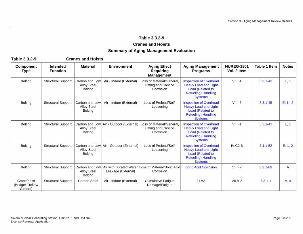
Section 3 - Aging Management Review Results
Salem Nuclear Generating Station, Unit No. 1 and Unit No. 2 Page 3.3-206 License Renewal Application
Table 3.3.2-9 Cranes and Hoists
Summary of Aging Management Evaluation
Table 3.3.2-9 Cranes and Hoists
Component Type
Intended Function
Material Environment Aging Effect Requiring
Management
Aging Management Programs
NUREG-1801 Vol. 2 Item
Table 1 Item Notes
Bolting Structural Support Carbon and Low Alloy Steel
Bolting
Air - Indoor (External) Loss of Material/General, Pitting and Crevice
Corrosion
Inspection of Overhead Heavy Load and Light
Load (Related to Refueling) Handling
Systems
VII.I-4 3.3.1-43 E, 1
Bolting Structural Support Carbon and Low Alloy Steel
Bolting
Air - Indoor (External) Loss of Preload/Self-Loosening
Inspection of Overhead Heavy Load and Light
Load (Related to Refueling) Handling
Systems
VII.I-5 3.3.1-45 E, 1, 2
Bolting Structural Support Carbon and Low Alloy Steel
Bolting
Air - Outdoor (External) Loss of Material/General, Pitting and Crevice
Corrosion
Inspection of Overhead Heavy Load and Light
Load (Related to Refueling) Handling
Systems
VII.I-1 3.3.1-43 E, 1
Bolting Structural Support Carbon and Low Alloy Steel
Bolting
Air - Outdoor (External) Loss of Preload/Self-Loosening
Inspection of Overhead Heavy Load and Light
Load (Related to Refueling) Handling
Systems
IV.C2-8 3.1.1-52 E, 1, 2
Bolting Structural Support Carbon and Low Alloy Steel
Bolting
Air with Borated Water Leakage (External)
Loss of Material/Boric Acid Corrosion
Boric Acid Corrosion VII.I-2 3.3.1-89 A
Crane/hoist (Bridge/ Trolley/
Girders)
Structural Support Carbon Steel Air - Indoor (External) Cumulative Fatigue Damage/Fatigue
TLAA VII.B-2 3.3.1-1 A, 4
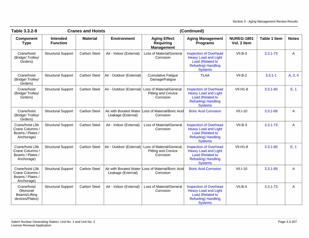
Section 3 - Aging Management Review Results
Salem Nuclear Generating Station, Unit No. 1 and Unit No. 2 Page 3.3-207 License Renewal Application
Table 3.3.2-9 Cranes and Hoists (Continued)
Component Type
Intended Function
Material Environment Aging Effect Requiring
Management
Aging Management Programs
NUREG-1801 Vol. 2 Item
Table 1 Item Notes
Crane/hoist (Bridge/ Trolley/
Girders)
Structural Support Carbon Steel Air - Indoor (External) Loss of Material/General Corrosion
Inspection of Overhead Heavy Load and Light
Load (Related to Refueling) Handling
Systems
VII.B-3 3.3.1-73 A
Crane/hoist (Bridge/ Trolley/
Girders)
Structural Support Carbon Steel Air - Outdoor (External) Cumulative Fatigue Damage/Fatigue
TLAA VII.B-2 3.3.1-1 A, 3, 4
Crane/hoist (Bridge/ Trolley/
Girders)
Structural Support Carbon Steel Air - Outdoor (External) Loss of Material/General, Pitting and Crevice
Corrosion
Inspection of Overhead Heavy Load and Light
Load (Related to Refueling) Handling
Systems
VII.H1-8 3.3.1-60 E, 1
Crane/hoist (Bridge/ Trolley/
Girders)
Structural Support Carbon Steel Air with Borated Water Leakage (External)
Loss of Material/Boric Acid Corrosion
Boric Acid Corrosion VII.I-10 3.3.1-89 A
Crane/hoist (Jib Crane Columns / Beams / Plates /
Anchorage)
Structural Support Carbon Steel Air - Indoor (External) Loss of Material/General Corrosion
Inspection of Overhead Heavy Load and Light
Load (Related to Refueling) Handling
Systems
VII.B-3 3.3.1-73 A
Crane/hoist (Jib Crane Columns / Beams / Plates /
Anchorage)
Structural Support Carbon Steel Air - Outdoor (External) Loss of Material/General, Pitting and Crevice
Corrosion
Inspection of Overhead Heavy Load and Light
Load (Related to Refueling) Handling
Systems
VII.H1-8 3.3.1-60 E, 1
Crane/hoist (Jib Crane Columns / Beams / Plates /
Anchorage)
Structural Support Carbon Steel Air with Borated Water Leakage (External)
Loss of Material/Boric Acid Corrosion
Boric Acid Corrosion VII.I-10 3.3.1-89 A
Crane/hoist (Monorail
Beams/Lifting devices/Plates)
Structural Support Carbon Steel Air - Indoor (External) Loss of Material/General Corrosion
Inspection of Overhead Heavy Load and Light
Load (Related to Refueling) Handling
Systems
VII.B-3 3.3.1-73 A

Section 3 - Aging Management Review Results
Salem Nuclear Generating Station, Unit No. 1 and Unit No. 2 Page 3.3-208 License Renewal Application
Table 3.3.2-9 Cranes and Hoists (Continued)
Component Type
Intended Function
Material Environment Aging Effect Requiring
Management
Aging Management Programs
NUREG-1801 Vol. 2 Item
Table 1 Item Notes
Crane/hoist (Monorail
Beams/Lifting devices/Plates)
Structural Support Carbon Steel Air - Outdoor (External) Loss of Material/General, Pitting and Crevice
Corrosion
Inspection of Overhead Heavy Load and Light
Load (Related to Refueling) Handling
Systems
VII.H1-8 3.3.1-60 E, 1
Crane/hoist (Monorail
Beams/Lifting devices/Plates)
Structural Support Carbon Steel Air with Borated Water Leakage (External)
Loss of Material/Boric Acid Corrosion
Boric Acid Corrosion VII.I-10 3.3.1-89 A
Crane/hoist (Rail System)
Structural Support Carbon Steel Air - Indoor (External) Loss of Material/General Corrosion
Inspection of Overhead Heavy Load and Light
Load (Related to Refueling) Handling
Systems
VII.B-3 3.3.1-73 C
Crane/hoist (Rail System)
Structural Support Carbon Steel Air - Indoor (External) Loss of Material/Wear Inspection of Overhead Heavy Load and Light
Load (Related to Refueling) Handling
Systems
VII.B-1 3.3.1-74 A
Crane/hoist (Rail System)
Structural Support Carbon Steel Air - Outdoor (External) Loss of Material/General, Pitting and Crevice
Corrosion
Inspection of Overhead Heavy Load and Light
Load (Related to Refueling) Handling
Systems
VII.H1-8 3.3.1-60 E, 1
Crane/hoist (Rail System)
Structural Support Carbon Steel Air - Outdoor (External) Loss of Material/Wear Inspection of Overhead Heavy Load and Light
Load (Related to Refueling) Handling
Systems
VII.B-1 3.3.1-74 A, 3
Crane/hoist (Rail System)
Structural Support Carbon Steel Air with Borated Water Leakage (External)
Loss of Material/Boric Acid Corrosion
Boric Acid Corrosion VII.I-10 3.3.1-89 A

Section 3 - Aging Management Review Results
Salem Nuclear Generating Station, Unit No. 1 and Unit No. 2 Page 3.3-209 License Renewal Application
Notes Definition of Note
A Consistent with NUREG-1801 item for component, material, environment, and aging effect. AMP is consistent with NUREG-1801 AMP.
B Consistent with NUREG-1801 item for component, material, environment, and aging effect. AMP takes some exceptions to NUREG-1801 AMP.
C Component is different, but consistent with NUREG-1801 item for material, environment, and aging effect. AMP is consistent with NUREG-1801 AMP.
D Component is different, but consistent with NUREG-1801 item for material, environment, and aging effect. AMP takes some exceptions to NUREG-1801 AMP.
E Consistent with NUREG-1801 item for material, environment and aging effect, but a different aging management program is credited or NUREG-1801 identifies a plant-specific aging management program.
F Material not in NUREG-1801 for this component.
G Environment not in NUREG-1801 for this component and material.
H Aging effect not in NUREG-1801 for this component, material and environment combination.
I Aging effect in NUREG-1801 for this component, material and environment combination is not applicable.
J Neither the component nor the material and environment combination is evaluated in NUREG-1801.
Plant Specific Notes:
1. The Inspection of Overhead Heavy Load and Light Load (Related to Refueling) Handling Systems program is substituted to manage the aging effect(s) applicable to this component type, material, and environment combination.
2. The aging mechanism(s) of thermal effects and gasket creep for this component, material, and environment combination are not applicable.
3. Air - Indoor and Air - Outdoor environments are considered equivalent for the cumulative fatigue aging effect or loss of material due to wear.
4. The TLAA designation in the Aging Management Program column indicates fatigue of this component is evaluated in Section 4.6

Section 3 - Aging Management Review Results
Salem Nuclear Generating Station, Unit No. 1 and Unit No. 2 Page 3.3-210 License Renewal Application
Table 3.3.2-10 Demineralized Water System
Summary of Aging Management Evaluation
Table 3.3.2-10 Demineralized Water System
Component Type
Intended Function
Material Environment Aging Effect Requiring
Management
Aging Management Programs
NUREG-1801 Vol. 2 Item
Table 1 Item Notes
Bolting Mechanical Closure Carbon and Low Alloy Steel
Bolting
Air - Indoor (External) Loss of Material/General, Pitting and Crevice
Corrosion
Bolting Integrity VII.I-4 3.3.1-43 B
Bolting Mechanical Closure Carbon and Low Alloy Steel
Bolting
Air - Indoor (External) Loss of Preload/Thermal Effects, Gasket Creep,
and Self-Loosening
Bolting Integrity VII.I-5 3.3.1-45 B
Bolting Mechanical Closure Carbon and Low Alloy Steel
Bolting
Air with Borated Water Leakage (External)
Loss of Material/Boric Acid Corrosion
Boric Acid Corrosion VII.I-2 3.3.1-89 A
Bolting Mechanical Closure Carbon and Low Alloy Steel
Bolting
Soil (External) Loss of Material/General, Pitting, Crevice, and
Microbiologically Influenced Corrosion
Bolting Integrity G, 1
Bolting Mechanical Closure Carbon and Low Alloy Steel
Bolting
Soil (External) Loss of Preload/Thermal Effects, Gasket Creep,
and Self-Loosening
Bolting Integrity G, 1
Flow Element Pressure Boundary Stainless Steel Air - Indoor (External) None None VII.J-15 3.3.1-94 A Flow Element Pressure Boundary Stainless Steel Treated Water (Internal) Loss of Material/Pitting
and Crevice Corrosion One-Time Inspection VIII.E-29 3.4.1-16 A
Flow Element Pressure Boundary Stainless Steel Treated Water (Internal) Loss of Material/Pitting and Crevice Corrosion
Water Chemistry VIII.E-29 3.4.1-16 A
Heat Exchanger Components
(Demineralized Water Storage
Tank)
Pressure Boundary Stainless Steel (Shell Side
Components)
Air - Indoor (External) None None VII.J-15 3.3.1-94 C

Section 3 - Aging Management Review Results
Salem Nuclear Generating Station, Unit No. 1 and Unit No. 2 Page 3.3-211 License Renewal Application
Table 3.3.2-10 Demineralized Water System (Continued)
Component Type
Intended Function
Material Environment Aging Effect Requiring
Management
Aging Management Programs
NUREG-1801 Vol. 2 Item
Table 1 Item Notes
Heat Exchanger Components
(Demineralized Water Storage
Tank)
Pressure Boundary Stainless Steel (Shell Side
Components)
Treated Water (Internal) Loss of Material/Pitting and Crevice Corrosion
One-Time Inspection VIII.F-27 3.4.1-16 A
Heat Exchanger Components
(Demineralized Water Storage
Tank)
Pressure Boundary Stainless Steel (Shell Side
Components)
Treated Water (Internal) Loss of Material/Pitting and Crevice Corrosion
Water Chemistry VIII.F-27 3.4.1-16 A
Heat Exchanger Components
(Demineralized Water Storage
Tank)
Pressure Boundary Stainless Steel (Tube Sheet)
Closed Cycle Cooling Water (Internal) > 140 F
Cracking/Stress Corrosion Cracking
Closed-Cycle Cooling Water System
VII.E3-2 3.3.1-46 B
Heat Exchanger Components
(Demineralized Water Storage
Tank)
Pressure Boundary Stainless Steel (Tube Sheet)
Closed Cycle Cooling Water (Internal) > 140 F
Loss of Material/Pitting and Crevice Corrosion
Closed-Cycle Cooling Water System
VII.C2-10 3.3.1-50 D
Heat Exchanger Components
(Demineralized Water Storage
Tank)
Pressure Boundary Stainless Steel (Tube Sheet)
Treated Water (External)
Loss of Material/Pitting and Crevice Corrosion
One-Time Inspection VIII.F-27 3.4.1-16 A
Heat Exchanger Components
(Demineralized Water Storage
Tank)
Pressure Boundary Stainless Steel (Tube Sheet)
Treated Water (External)
Loss of Material/Pitting and Crevice Corrosion
Water Chemistry VIII.F-27 3.4.1-16 A
Heat Exchanger Components
(Demineralized Water Storage
Tank)
Pressure Boundary Stainless Steel (Tubes)
Closed Cycle Cooling Water (Internal) > 140 F
Cracking/Stress Corrosion Cracking
Closed-Cycle Cooling Water System
VII.E3-2 3.3.1-46 B

Section 3 - Aging Management Review Results
Salem Nuclear Generating Station, Unit No. 1 and Unit No. 2 Page 3.3-212 License Renewal Application
Table 3.3.2-10 Demineralized Water System (Continued)
Component Type
Intended Function
Material Environment Aging Effect Requiring
Management
Aging Management Programs
NUREG-1801 Vol. 2 Item
Table 1 Item Notes
Heat Exchanger Components
(Demineralized Water Storage
Tank)
Pressure Boundary Stainless Steel (Tubes)
Closed Cycle Cooling Water (Internal) > 140 F
Loss of Material/Pitting and Crevice Corrosion
Closed-Cycle Cooling Water System
VII.C2-10 3.3.1-50 D
Heat Exchanger Components
(Demineralized Water Storage
Tank)
Pressure Boundary Stainless Steel (Tubes)
Treated Water (External)
Loss of Material/Pitting and Crevice Corrosion
One-Time Inspection VIII.G-32 3.4.1-16 C
Heat Exchanger Components
(Demineralized Water Storage
Tank)
Pressure Boundary Stainless Steel (Tubes)
Treated Water (External)
Loss of Material/Pitting and Crevice Corrosion
Water Chemistry VIII.G-32 3.4.1-16 C
Piping and Fittings Leakage Boundary Carbon Steel Air - Indoor (External) Loss of Material/General Corrosion
External Surfaces Monitoring
VII.I-8 3.3.1-58 A
Piping and Fittings Leakage Boundary Carbon Steel Air with Borated Water Leakage (External)
Loss of Material/Boric Acid Corrosion
Boric Acid Corrosion VII.I-10 3.3.1-89 A
Piping and Fittings Leakage Boundary Carbon Steel Treated Water (Internal) Loss of Material/General, Pitting and Crevice
Corrosion
One-Time Inspection VIII.E-34 3.4.1-4 A
Piping and Fittings Leakage Boundary Carbon Steel Treated Water (Internal) Loss of Material/General, Pitting and Crevice
Corrosion
Water Chemistry VIII.E-34 3.4.1-4 A
Piping and Fittings Leakage Boundary Stainless Steel Air - Indoor (External) None None VII.J-15 3.3.1-94 A Piping and Fittings Leakage Boundary Stainless Steel Air with Borated Water
Leakage (External) None None VII.J-16 3.3.1-99 A
Piping and Fittings Leakage Boundary Stainless Steel Treated Water (Internal) Loss of Material/Pitting and Crevice Corrosion
One-Time Inspection VIII.E-29 3.4.1-16 A
Piping and Fittings Leakage Boundary Stainless Steel Treated Water (Internal) Loss of Material/Pitting and Crevice Corrosion
Water Chemistry VIII.E-29 3.4.1-16 A
Piping and Fittings Pressure Boundary Carbon Steel Air - Indoor (External) Loss of Material/General Corrosion
External Surfaces Monitoring
VII.I-8 3.3.1-58 A
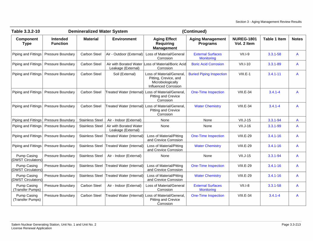
Section 3 - Aging Management Review Results
Salem Nuclear Generating Station, Unit No. 1 and Unit No. 2 Page 3.3-213 License Renewal Application
Table 3.3.2-10 Demineralized Water System (Continued)
Component Type
Intended Function
Material Environment Aging Effect Requiring
Management
Aging Management Programs
NUREG-1801 Vol. 2 Item
Table 1 Item Notes
Piping and Fittings Pressure Boundary Carbon Steel Air - Outdoor (External) Loss of Material/General Corrosion
External Surfaces Monitoring
VII.I-9 3.3.1-58 A
Piping and Fittings Pressure Boundary Carbon Steel Air with Borated Water Leakage (External)
Loss of Material/Boric Acid Corrosion
Boric Acid Corrosion VII.I-10 3.3.1-89 A
Piping and Fittings Pressure Boundary Carbon Steel Soil (External) Loss of Material/General, Pitting, Crevice, and
Microbiologically Influenced Corrosion
Buried Piping Inspection VIII.E-1 3.4.1-11 A
Piping and Fittings Pressure Boundary Carbon Steel Treated Water (Internal) Loss of Material/General, Pitting and Crevice
Corrosion
One-Time Inspection VIII.E-34 3.4.1-4 A
Piping and Fittings Pressure Boundary Carbon Steel Treated Water (Internal) Loss of Material/General, Pitting and Crevice
Corrosion
Water Chemistry VIII.E-34 3.4.1-4 A
Piping and Fittings Pressure Boundary Stainless Steel Air - Indoor (External) None None VII.J-15 3.3.1-94 A Piping and Fittings Pressure Boundary Stainless Steel Air with Borated Water
Leakage (External) None None VII.J-16 3.3.1-99 A
Piping and Fittings Pressure Boundary Stainless Steel Treated Water (Internal) Loss of Material/Pitting and Crevice Corrosion
One-Time Inspection VIII.E-29 3.4.1-16 A
Piping and Fittings Pressure Boundary Stainless Steel Treated Water (Internal) Loss of Material/Pitting and Crevice Corrosion
Water Chemistry VIII.E-29 3.4.1-16 A
Pump Casing (DWST Circulators)
Pressure Boundary Stainless Steel Air - Indoor (External) None None VII.J-15 3.3.1-94 A
Pump Casing (DWST Circulators)
Pressure Boundary Stainless Steel Treated Water (Internal) Loss of Material/Pitting and Crevice Corrosion
One-Time Inspection VIII.E-29 3.4.1-16 A
Pump Casing (DWST Circulators)
Pressure Boundary Stainless Steel Treated Water (Internal) Loss of Material/Pitting and Crevice Corrosion
Water Chemistry VIII.E-29 3.4.1-16 A
Pump Casing (Transfer Pumps)
Pressure Boundary Carbon Steel Air - Indoor (External) Loss of Material/General Corrosion
External Surfaces Monitoring
VII.I-8 3.3.1-58 A
Pump Casing (Transfer Pumps)
Pressure Boundary Carbon Steel Treated Water (Internal) Loss of Material/General, Pitting and Crevice
Corrosion
One-Time Inspection VIII.E-34 3.4.1-4 A

Section 3 - Aging Management Review Results
Salem Nuclear Generating Station, Unit No. 1 and Unit No. 2 Page 3.3-214 License Renewal Application
Table 3.3.2-10 Demineralized Water System (Continued)
Component Type
Intended Function
Material Environment Aging Effect Requiring
Management
Aging Management Programs
NUREG-1801 Vol. 2 Item
Table 1 Item Notes
Pump Casing (Transfer Pumps)
Pressure Boundary Carbon Steel Treated Water (Internal) Loss of Material/General, Pitting and Crevice
Corrosion
Water Chemistry VIII.E-34 3.4.1-4 A
Restricting Orifices Pressure Boundary Stainless Steel Air - Indoor (External) None None VII.J-15 3.3.1-94 A Restricting Orifices Pressure Boundary Stainless Steel Treated Water (Internal) Loss of Material/Pitting
and Crevice Corrosion One-Time Inspection VIII.E-29 3.4.1-16 A
Restricting Orifices Pressure Boundary Stainless Steel Treated Water (Internal) Loss of Material/Pitting and Crevice Corrosion
Water Chemistry VIII.E-29 3.4.1-16 A
Tanks (DM Storage Tanks)
Pressure Boundary Aluminum Air - Outdoor (External) Loss of Material/Pitting and Crevice Corrosion
Aboveground Non-Steel Tanks
III.B4-7 3.5.1-50 E, 2
Tanks (DM Storage Tanks)
Pressure Boundary Aluminum Soil (External) Loss of Material/Pitting, Crevice, and
Microbiologically Influenced Corrosion
Aboveground Non-Steel Tanks
G
Tanks (DM Storage Tanks)
Pressure Boundary Aluminum Treated Water (Internal) Loss of Material/Pitting and Crevice Corrosion
One-Time Inspection VIII.E-15 3.4.1-15 C
Tanks (DM Storage Tanks)
Pressure Boundary Aluminum Treated Water (Internal) Loss of Material/Pitting and Crevice Corrosion
Water Chemistry VIII.E-15 3.4.1-15 C
Tanks (Water Heater)
Leakage Boundary Stainless Steel Air - Indoor (External) None None VII.J-15 3.3.1-94 C
Tanks (Water Heater)
Leakage Boundary Stainless Steel Air with Borated Water Leakage (External)
None None VII.J-16 3.3.1-99 C
Tanks (Water Heater)
Leakage Boundary Stainless Steel Treated Water (Internal) > 140 F
Cracking/Stress Corrosion Cracking
One-Time Inspection VIII.F-24 3.4.1-14 C
Tanks (Water Heater)
Leakage Boundary Stainless Steel Treated Water (Internal) > 140 F
Cracking/Stress Corrosion Cracking
Water Chemistry VIII.F-24 3.4.1-14 C
Tanks (Water Heater)
Leakage Boundary Stainless Steel Treated Water (Internal) > 140 F
Loss of Material/Pitting and Crevice Corrosion
One-Time Inspection VIII.F-23 3.4.1-16 C
Tanks (Water Heater)
Leakage Boundary Stainless Steel Treated Water (Internal) > 140 F
Loss of Material/Pitting and Crevice Corrosion
Water Chemistry VIII.F-23 3.4.1-16 C
Valve Body Leakage Boundary Carbon Steel Air - Indoor (External) Loss of Material/General Corrosion
External Surfaces Monitoring
VII.I-8 3.3.1-58 A
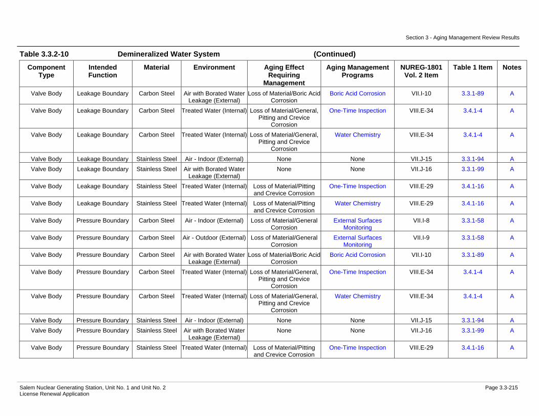
Section 3 - Aging Management Review Results
Salem Nuclear Generating Station, Unit No. 1 and Unit No. 2 Page 3.3-215 License Renewal Application
Table 3.3.2-10 Demineralized Water System (Continued)
Component Type
Intended Function
Material Environment Aging Effect Requiring
Management
Aging Management Programs
NUREG-1801 Vol. 2 Item
Table 1 Item Notes
Valve Body Leakage Boundary Carbon Steel Air with Borated Water Leakage (External)
Loss of Material/Boric Acid Corrosion
Boric Acid Corrosion VII.I-10 3.3.1-89 A
Valve Body Leakage Boundary Carbon Steel Treated Water (Internal) Loss of Material/General, Pitting and Crevice
Corrosion
One-Time Inspection VIII.E-34 3.4.1-4 A
Valve Body Leakage Boundary Carbon Steel Treated Water (Internal) Loss of Material/General, Pitting and Crevice
Corrosion
Water Chemistry VIII.E-34 3.4.1-4 A
Valve Body Leakage Boundary Stainless Steel Air - Indoor (External) None None VII.J-15 3.3.1-94 A Valve Body Leakage Boundary Stainless Steel Air with Borated Water
Leakage (External) None None VII.J-16 3.3.1-99 A
Valve Body Leakage Boundary Stainless Steel Treated Water (Internal) Loss of Material/Pitting and Crevice Corrosion
One-Time Inspection VIII.E-29 3.4.1-16 A
Valve Body Leakage Boundary Stainless Steel Treated Water (Internal) Loss of Material/Pitting and Crevice Corrosion
Water Chemistry VIII.E-29 3.4.1-16 A
Valve Body Pressure Boundary Carbon Steel Air - Indoor (External) Loss of Material/General Corrosion
External Surfaces Monitoring
VII.I-8 3.3.1-58 A
Valve Body Pressure Boundary Carbon Steel Air - Outdoor (External) Loss of Material/General Corrosion
External Surfaces Monitoring
VII.I-9 3.3.1-58 A
Valve Body Pressure Boundary Carbon Steel Air with Borated Water Leakage (External)
Loss of Material/Boric Acid Corrosion
Boric Acid Corrosion VII.I-10 3.3.1-89 A
Valve Body Pressure Boundary Carbon Steel Treated Water (Internal) Loss of Material/General, Pitting and Crevice
Corrosion
One-Time Inspection VIII.E-34 3.4.1-4 A
Valve Body Pressure Boundary Carbon Steel Treated Water (Internal) Loss of Material/General, Pitting and Crevice
Corrosion
Water Chemistry VIII.E-34 3.4.1-4 A
Valve Body Pressure Boundary Stainless Steel Air - Indoor (External) None None VII.J-15 3.3.1-94 A Valve Body Pressure Boundary Stainless Steel Air with Borated Water
Leakage (External) None None VII.J-16 3.3.1-99 A
Valve Body Pressure Boundary Stainless Steel Treated Water (Internal) Loss of Material/Pitting and Crevice Corrosion
One-Time Inspection VIII.E-29 3.4.1-16 A

Section 3 - Aging Management Review Results
Salem Nuclear Generating Station, Unit No. 1 and Unit No. 2 Page 3.3-216 License Renewal Application
Table 3.3.2-10 Demineralized Water System (Continued)
Component Type
Intended Function
Material Environment Aging Effect Requiring
Management
Aging Management Programs
NUREG-1801 Vol. 2 Item
Table 1 Item Notes
Valve Body Pressure Boundary Stainless Steel Treated Water (Internal) Loss of Material/Pitting and Crevice Corrosion
Water Chemistry VIII.E-29 3.4.1-16 A
Notes Definition of Note
A Consistent with NUREG-1801 item for component, material, environment, and aging effect. AMP is consistent with NUREG-1801 AMP.
B Consistent with NUREG-1801 item for component, material, environment, and aging effect. AMP takes some exceptions to NUREG-1801 AMP.
C Component is different, but consistent with NUREG-1801 item for material, environment, and aging effect. AMP is consistent with NUREG-1801 AMP.
D Component is different, but consistent with NUREG-1801 item for material, environment, and aging effect. AMP takes some exceptions to NUREG-1801 AMP.
E Consistent with NUREG-1801 item for material, environment and aging effect, but a different aging management program is credited or NUREG-1801 identifies a plant-specific aging management program.
F Material not in NUREG-1801 for this component.
G Environment not in NUREG-1801 for this component and material.
H Aging effect not in NUREG-1801 for this component, material and environment combination.
I Aging effect in NUREG-1801 for this component, material and environment combination is not applicable.
J Neither the component nor the material and environment combination is evaluated in NUREG-1801.
Plant Specific Notes:
1. The aging effects for closure bolting in a soil environment include loss of material and loss of preload. External inspections of buried bolting will occur in accordance with the frequency outlined in the Buried Piping Inspection program.
2. The Aboveground Non-Steel Tanks program is substituted to manage the aging effect(s) applicable to this component type, material, and environment combination.

Section 3 - Aging Management Review Results
Salem Nuclear Generating Station, Unit No. 1 and Unit No. 2 Page 3.3-217 License Renewal Application
Table 3.3.2-11 Emergency Diesel Generator & Auxiliaries System
Summary of Aging Management Evaluation
Table 3.3.2-11 Emergency Diesel Generator & Auxiliaries System
Component Type
Intended Function
Material Environment Aging Effect Requiring
Management
Aging Management Programs
NUREG-1801 Vol. 2 Item
Table 1 Item Notes
Bolting Mechanical Closure Carbon and Low Alloy Steel
Bolting
Air - Indoor (External) Loss of Material/General, Pitting and Crevice
Corrosion
Bolting Integrity VII.I-4 3.3.1-43 B
Bolting Mechanical Closure Carbon and Low Alloy Steel
Bolting
Air - Indoor (External) Loss of Preload/Thermal Effects, Gasket Creep,
and Self-Loosening
Bolting Integrity VII.I-5 3.3.1-45 B
Electric Heaters (Aftercooler Heater
Housing)
Pressure Boundary Carbon Steel Air - Indoor (External) Loss of Material/General Corrosion
External Surfaces Monitoring
VII.I-8 3.3.1-58 A
Electric Heaters (Aftercooler Heater
Housing)
Pressure Boundary Carbon Steel Closed Cycle Cooling Water (Internal)
Loss of Material/General, Pitting and Crevice
Corrosion
Closed-Cycle Cooling Water System
VII.H2-23 3.3.1-47 B
Electric Heaters (Lube Oil Heater
Housing)
Pressure Boundary Carbon Steel Air - Indoor (External) Loss of Material/General Corrosion
External Surfaces Monitoring
VII.I-8 3.3.1-58 A
Electric Heaters (Lube Oil Heater
Housing)
Pressure Boundary Carbon Steel Lubricating Oil (Internal) Loss of Material/General, Pitting and Crevice
Corrosion
Lubricating Oil Analysis VII.H2-20 3.3.1-14 B
Electric Heaters (Lube Oil Heater
Housing)
Pressure Boundary Carbon Steel Lubricating Oil (Internal) Loss of Material/General, Pitting and Crevice
Corrosion
One-Time Inspection VII.H2-20 3.3.1-14 A
Expansion Joints Pressure Boundary Stainless Steel Air - Indoor (External) None None VII.J-15 3.3.1-94 A Expansion Joints Pressure Boundary Stainless Steel Diesel Exhaust
(Internal) Cracking/Stress Corrosion
Cracking Periodic Inspection VII.H2-1 3.3.1-6 E, 1
Expansion Joints Pressure Boundary Stainless Steel Diesel Exhaust (Internal)
Loss of Material/Pitting and Crevice Corrosion
Periodic Inspection VII.H2-2 3.3.1-18 E, 1
Filter Housing Pressure Boundary Carbon Steel Air - Indoor (External) Loss of Material/General Corrosion
External Surfaces Monitoring
VII.I-8 3.3.1-58 A

Section 3 - Aging Management Review Results
Salem Nuclear Generating Station, Unit No. 1 and Unit No. 2 Page 3.3-218 License Renewal Application
Table 3.3.2-11 Emergency Diesel Generator & Auxiliaries System (Continued)
Component Type
Intended Function
Material Environment Aging Effect Requiring
Management
Aging Management Programs
NUREG-1801 Vol. 2 Item
Table 1 Item Notes
Filter Housing Pressure Boundary Carbon Steel Air/Gas - Wetted (Internal)
Loss of Material/General, Pitting and Crevice
Corrosion
Inspection of Internal Surfaces in Miscellaneous
Piping and Ducting Components
VII.H2-21 3.3.1-71 A
Filter Housing Pressure Boundary Carbon Steel Lubricating Oil (Internal) Loss of Material/General, Pitting and Crevice
Corrosion
Lubricating Oil Analysis VII.H2-20 3.3.1-14 B
Filter Housing Pressure Boundary Carbon Steel Lubricating Oil (Internal) Loss of Material/General, Pitting and Crevice
Corrosion
One-Time Inspection VII.H2-20 3.3.1-14 A
Flow Device Pressure Boundary Stainless Steel Air - Indoor (External) None None VII.J-15 3.3.1-94 A Flow Device Pressure Boundary Stainless Steel Lubricating Oil (Internal) Loss of Material/Pitting
and Crevice Corrosion Lubricating Oil Analysis VII.H2-17 3.3.1-33 B, 2
Flow Device Pressure Boundary Stainless Steel Lubricating Oil (Internal) Loss of Material/Pitting and Crevice Corrosion
One-Time Inspection VII.H2-17 3.3.1-33 A, 2
Flow Element Pressure Boundary Stainless Steel Air - Indoor (External) None None VII.J-15 3.3.1-94 A Flow Element Pressure Boundary Stainless Steel Closed Cycle Cooling
Water (Internal) > 140 FCracking/Stress Corrosion
Cracking Closed-Cycle Cooling
Water System VII.C2-11 3.3.1-46 B
Flow Element Pressure Boundary Stainless Steel Closed Cycle Cooling Water (Internal) > 140 F
Loss of Material/Pitting and Crevice Corrosion
Closed-Cycle Cooling Water System
VII.C2-10 3.3.1-50 B
Heat Exchanger Components
(Jacket Water Heat Exchanger)
Evaluated with the Service Water
System
Not Applicable Not Applicable Not Applicable Not Applicable 6
Heat Exchanger Components
(Lubricating Oil Heat Exchanger)
Evaluated with the Service Water
System
Not Applicable Not Applicable Not Applicable Not Applicable 6
Piping and Fittings Pressure Boundary Carbon Steel Air - Indoor (External) Loss of Material/General Corrosion
External Surfaces Monitoring
VII.I-8 3.3.1-58 A
Piping and Fittings Pressure Boundary Carbon Steel Air - Outdoor (External) Loss of Material/General, Pitting and Crevice
Corrosion
External Surfaces Monitoring
VII.H1-8 3.3.1-60 A

Section 3 - Aging Management Review Results
Salem Nuclear Generating Station, Unit No. 1 and Unit No. 2 Page 3.3-219 License Renewal Application
Table 3.3.2-11 Emergency Diesel Generator & Auxiliaries System (Continued)
Component Type
Intended Function
Material Environment Aging Effect Requiring
Management
Aging Management Programs
NUREG-1801 Vol. 2 Item
Table 1 Item Notes
Piping and Fittings Pressure Boundary Carbon Steel Air/Gas - Wetted (Internal)
Loss of Material/General, Pitting and Crevice
Corrosion
Inspection of Internal Surfaces in Miscellaneous
Piping and Ducting Components
VII.H2-21 3.3.1-71 A
Piping and Fittings Pressure Boundary Carbon Steel Closed Cycle Cooling Water (Internal)
Loss of Material/General, Pitting and Crevice
Corrosion
Closed-Cycle Cooling Water System
VII.H2-23 3.3.1-47 B
Piping and Fittings Pressure Boundary Carbon Steel Diesel Exhaust (Internal)
Loss of Material/General, Pitting and Crevice
Corrosion
Inspection of Internal Surfaces in Miscellaneous
Piping and Ducting Components
VII.H2-2 3.3.1-18 E, 1
Piping and Fittings Pressure Boundary Carbon Steel Lubricating Oil (Internal) Loss of Material/General, Pitting and Crevice
Corrosion
Lubricating Oil Analysis VII.H2-20 3.3.1-14 B
Piping and Fittings Pressure Boundary Carbon Steel Lubricating Oil (Internal) Loss of Material/General, Pitting and Crevice
Corrosion
One-Time Inspection VII.H2-20 3.3.1-14 A
Piping and Fittings Pressure Boundary Stainless Steel Air - Indoor (External) None None VII.J-15 3.3.1-94 A Piping and Fittings Pressure Boundary Stainless Steel Air/Gas - Wetted
(Internal) Loss of Material/Pitting and Crevice Corrosion
Periodic Inspection VII.D-4 3.3.1-54 E, 3
Piping and Fittings Pressure Boundary Stainless Steel Closed Cycle Cooling Water (Internal) > 140 F
Cracking/Stress Corrosion Cracking
Closed-Cycle Cooling Water System
VII.C2-11 3.3.1-46 B
Piping and Fittings Pressure Boundary Stainless Steel Closed Cycle Cooling Water (Internal) > 140 F
Loss of Material/Pitting and Crevice Corrosion
Closed-Cycle Cooling Water System
VII.C2-10 3.3.1-50 B
Piping and Fittings Pressure Boundary Stainless Steel Lubricating Oil (Internal) Loss of Material/Pitting and Crevice Corrosion
Lubricating Oil Analysis VII.H2-17 3.3.1-33 B, 2
Piping and Fittings Pressure Boundary Stainless Steel Lubricating Oil (Internal) Loss of Material/Pitting and Crevice Corrosion
One-Time Inspection VII.H2-17 3.3.1-33 A, 2
Piping and Fittings Structural Support Stainless Steel Air - Indoor (External) None None VII.J-15 3.3.1-94 A Piping and Fittings Structural Support Stainless Steel Air/Gas - Wetted
(Internal) Loss of Material/Pitting and Crevice Corrosion
Periodic Inspection VII.D-4 3.3.1-54 E, 3
Pump Casing (Engine Driven Lube Oil Pump)
Pressure Boundary Gray Cast Iron Air - Indoor (External) Loss of Material/General Corrosion
External Surfaces Monitoring
VII.I-8 3.3.1-58 A
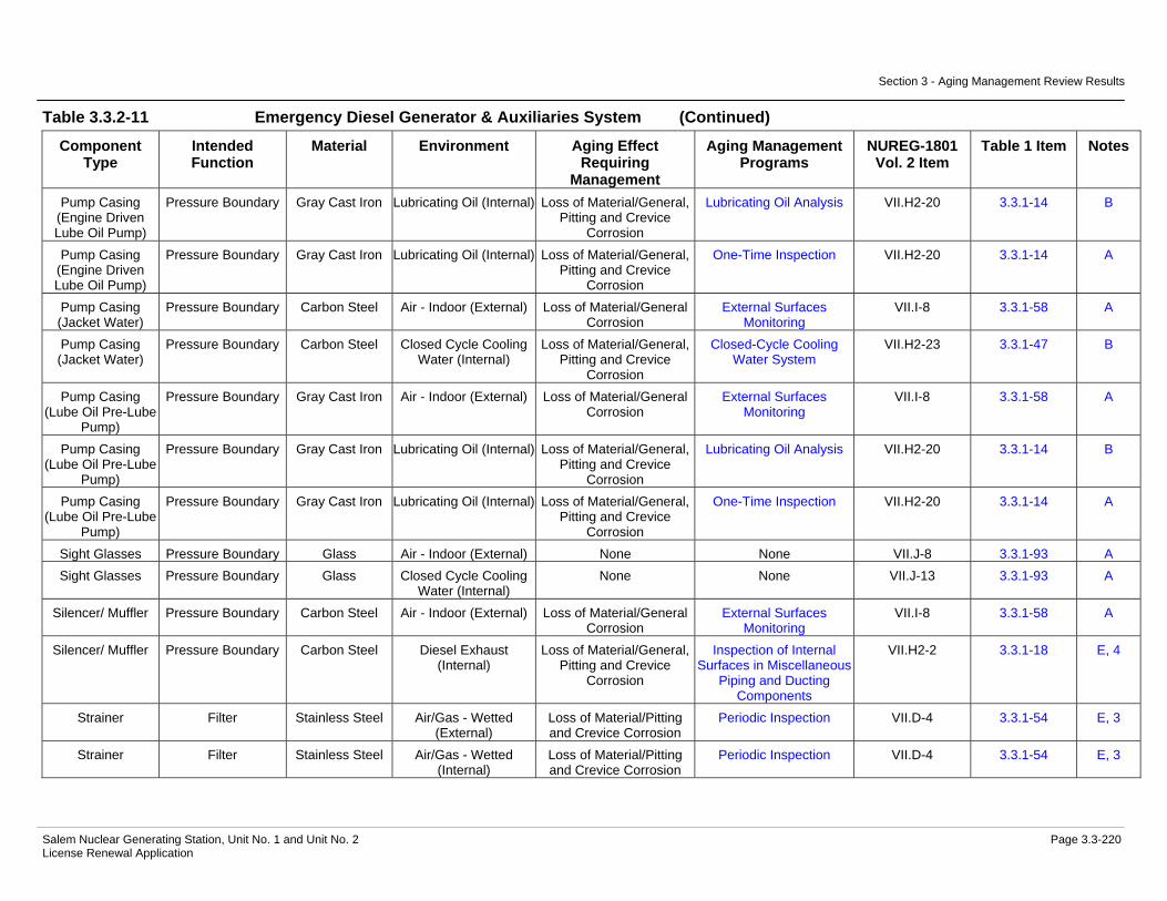
Section 3 - Aging Management Review Results
Salem Nuclear Generating Station, Unit No. 1 and Unit No. 2 Page 3.3-220 License Renewal Application
Table 3.3.2-11 Emergency Diesel Generator & Auxiliaries System (Continued)
Component Type
Intended Function
Material Environment Aging Effect Requiring
Management
Aging Management Programs
NUREG-1801 Vol. 2 Item
Table 1 Item Notes
Pump Casing (Engine Driven Lube Oil Pump)
Pressure Boundary Gray Cast Iron Lubricating Oil (Internal) Loss of Material/General, Pitting and Crevice
Corrosion
Lubricating Oil Analysis VII.H2-20 3.3.1-14 B
Pump Casing (Engine Driven Lube Oil Pump)
Pressure Boundary Gray Cast Iron Lubricating Oil (Internal) Loss of Material/General, Pitting and Crevice
Corrosion
One-Time Inspection VII.H2-20 3.3.1-14 A
Pump Casing (Jacket Water)
Pressure Boundary Carbon Steel Air - Indoor (External) Loss of Material/General Corrosion
External Surfaces Monitoring
VII.I-8 3.3.1-58 A
Pump Casing (Jacket Water)
Pressure Boundary Carbon Steel Closed Cycle Cooling Water (Internal)
Loss of Material/General, Pitting and Crevice
Corrosion
Closed-Cycle Cooling Water System
VII.H2-23 3.3.1-47 B
Pump Casing (Lube Oil Pre-Lube
Pump)
Pressure Boundary Gray Cast Iron Air - Indoor (External) Loss of Material/General Corrosion
External Surfaces Monitoring
VII.I-8 3.3.1-58 A
Pump Casing (Lube Oil Pre-Lube
Pump)
Pressure Boundary Gray Cast Iron Lubricating Oil (Internal) Loss of Material/General, Pitting and Crevice
Corrosion
Lubricating Oil Analysis VII.H2-20 3.3.1-14 B
Pump Casing (Lube Oil Pre-Lube
Pump)
Pressure Boundary Gray Cast Iron Lubricating Oil (Internal) Loss of Material/General, Pitting and Crevice
Corrosion
One-Time Inspection VII.H2-20 3.3.1-14 A
Sight Glasses Pressure Boundary Glass Air - Indoor (External) None None VII.J-8 3.3.1-93 A Sight Glasses Pressure Boundary Glass Closed Cycle Cooling
Water (Internal) None None VII.J-13 3.3.1-93 A
Silencer/ Muffler Pressure Boundary Carbon Steel Air - Indoor (External) Loss of Material/General Corrosion
External Surfaces Monitoring
VII.I-8 3.3.1-58 A
Silencer/ Muffler Pressure Boundary Carbon Steel Diesel Exhaust (Internal)
Loss of Material/General, Pitting and Crevice
Corrosion
Inspection of Internal Surfaces in Miscellaneous
Piping and Ducting Components
VII.H2-2 3.3.1-18 E, 4
Strainer Filter Stainless Steel Air/Gas - Wetted (External)
Loss of Material/Pitting and Crevice Corrosion
Periodic Inspection VII.D-4 3.3.1-54 E, 3
Strainer Filter Stainless Steel Air/Gas - Wetted (Internal)
Loss of Material/Pitting and Crevice Corrosion
Periodic Inspection VII.D-4 3.3.1-54 E, 3

Section 3 - Aging Management Review Results
Salem Nuclear Generating Station, Unit No. 1 and Unit No. 2 Page 3.3-221 License Renewal Application
Table 3.3.2-11 Emergency Diesel Generator & Auxiliaries System (Continued)
Component Type
Intended Function
Material Environment Aging Effect Requiring
Management
Aging Management Programs
NUREG-1801 Vol. 2 Item
Table 1 Item Notes
Strainer Filter Stainless Steel Lubricating Oil (External)
Loss of Material/Pitting and Crevice Corrosion
Lubricating Oil Analysis VII.H2-17 3.3.1-33 B, 2
Strainer Filter Stainless Steel Lubricating Oil (External)
Loss of Material/Pitting and Crevice Corrosion
One-Time Inspection VII.H2-17 3.3.1-33 A, 2
Strainer Filter Stainless Steel Lubricating Oil (Internal) Loss of Material/Pitting and Crevice Corrosion
Lubricating Oil Analysis VII.H2-17 3.3.1-33 B, 2
Strainer Filter Stainless Steel Lubricating Oil (Internal) Loss of Material/Pitting and Crevice Corrosion
One-Time Inspection VII.H2-17 3.3.1-33 A, 2
Strainer Body Pressure Boundary Gray Cast Iron Air - Indoor (External) Loss of Material/General Corrosion
External Surfaces Monitoring
VII.I-8 3.3.1-58 A
Strainer Body Pressure Boundary Gray Cast Iron Lubricating Oil (Internal) Loss of Material/General, Pitting and Crevice
Corrosion
Lubricating Oil Analysis VII.H2-20 3.3.1-14 B
Strainer Body Pressure Boundary Gray Cast Iron Lubricating Oil (Internal) Loss of Material/General, Pitting and Crevice
Corrosion
One-Time Inspection VII.H2-20 3.3.1-14 A
Strainer Body Pressure Boundary Stainless Steel Air - Indoor (External) None None VII.J-15 3.3.1-94 A Strainer Body Pressure Boundary Stainless Steel Air/Gas - Wetted
(Internal) Loss of Material/Pitting and Crevice Corrosion
Periodic Inspection VII.D-4 3.3.1-54 E, 3
Tanks (Jacket Water Expansion)
Pressure Boundary Carbon Steel Air - Indoor (External) Loss of Material/General Corrosion
External Surfaces Monitoring
VII.I-8 3.3.1-58 A
Tanks (Jacket Water Expansion)
Pressure Boundary Carbon Steel Closed Cycle Cooling Water (Internal)
Loss of Material/General, Pitting and Crevice
Corrosion
Closed-Cycle Cooling Water System
VII.H2-23 3.3.1-47 B
Tanks (Starting Air Receiver)
Pressure Boundary Carbon Steel Air - Indoor (External) Loss of Material/General Corrosion
External Surfaces Monitoring
VII.I-8 3.3.1-58 A
Tanks (Starting Air Receiver)
Pressure Boundary Carbon Steel Air/Gas - Wetted (Internal)
Loss of Material/General, Pitting and Crevice
Corrosion
Inspection of Internal Surfaces in Miscellaneous
Piping and Ducting Components
VII.H2-21 3.3.1-71 C
Tanks (Turbo Boost Air Receiver)
Pressure Boundary Carbon Steel Air - Indoor (External) Loss of Material/General Corrosion
External Surfaces Monitoring
VII.I-8 3.3.1-58 A

Section 3 - Aging Management Review Results
Salem Nuclear Generating Station, Unit No. 1 and Unit No. 2 Page 3.3-222 License Renewal Application
Table 3.3.2-11 Emergency Diesel Generator & Auxiliaries System (Continued)
Component Type
Intended Function
Material Environment Aging Effect Requiring
Management
Aging Management Programs
NUREG-1801 Vol. 2 Item
Table 1 Item Notes
Tanks (Turbo Boost Air Receiver)
Pressure Boundary Carbon Steel Air/Gas - Wetted (Internal)
Loss of Material/General, Pitting and Crevice
Corrosion
Inspection of Internal Surfaces in Miscellaneous
Piping and Ducting Components
VII.H2-21 3.3.1-71 C
Thermowell Pressure Boundary Stainless Steel Air - Indoor (External) None None VII.J-15 3.3.1-94 A Thermowell Pressure Boundary Stainless Steel Closed Cycle Cooling
Water (Internal) > 140 FCracking/Stress Corrosion
Cracking Closed-Cycle Cooling
Water System VII.C2-11 3.3.1-46 B
Thermowell Pressure Boundary Stainless Steel Closed Cycle Cooling Water (Internal) > 140 F
Loss of Material/Pitting and Crevice Corrosion
Closed-Cycle Cooling Water System
VII.C2-10 3.3.1-50 B
Thermowell Pressure Boundary Stainless Steel Lubricating Oil (External)
Loss of Material/Pitting and Crevice Corrosion
Lubricating Oil Analysis VII.H2-17 3.3.1-33 B, 2
Thermowell Pressure Boundary Stainless Steel Lubricating Oil (External)
Loss of Material/Pitting and Crevice Corrosion
One-Time Inspection VII.H2-17 3.3.1-33 A, 2
Valve Body Pressure Boundary Aluminum Air - Indoor (External) None None V.F-2 3.2.1-50 A Valve Body Pressure Boundary Aluminum Air/Gas - Wetted
(Internal) Loss of Material/Pitting and Crevice Corrosion
Periodic Inspection VII.F4-10 3.3.1-27 E, 1
Valve Body Pressure Boundary Carbon Steel Air - Indoor (External) Loss of Material/General Corrosion
External Surfaces Monitoring
VII.I-8 3.3.1-58 A
Valve Body Pressure Boundary Carbon Steel Air/Gas - Wetted (Internal)
Loss of Material/General, Pitting and Crevice
Corrosion
Inspection of Internal Surfaces in Miscellaneous
Piping and Ducting Components
VII.H2-21 3.3.1-71 A
Valve Body Pressure Boundary Carbon Steel Lubricating Oil (Internal) Loss of Material/General, Pitting and Crevice
Corrosion
Lubricating Oil Analysis VII.H2-20 3.3.1-14 B
Valve Body Pressure Boundary Carbon Steel Lubricating Oil (Internal) Loss of Material/General, Pitting and Crevice
Corrosion
One-Time Inspection VII.H2-20 3.3.1-14 A
Valve Body Pressure Boundary Copper Alloy with 15% Zinc or More
Air - Indoor (External) None None VIII.I-2 3.4.1-41 A
Valve Body Pressure Boundary Copper Alloy with 15% Zinc or More
Air/Gas - Wetted (Internal)
Loss of Material/Pitting and Crevice Corrosion
Periodic Inspection VII.G-9 3.3.1-28 E, 1

Section 3 - Aging Management Review Results
Salem Nuclear Generating Station, Unit No. 1 and Unit No. 2 Page 3.3-223 License Renewal Application
Table 3.3.2-11 Emergency Diesel Generator & Auxiliaries System (Continued)
Component Type
Intended Function
Material Environment Aging Effect Requiring
Management
Aging Management Programs
NUREG-1801 Vol. 2 Item
Table 1 Item Notes
Valve Body Pressure Boundary Copper Alloy with 15% Zinc or More
Closed Cycle Cooling Water (External) > 140
F
Loss of Material/Pitting and Crevice Corrosion
Closed-Cycle Cooling Water System
VII.C2-4 3.3.1-51 B, 5
Valve Body Pressure Boundary Copper Alloy with 15% Zinc or More
Closed Cycle Cooling Water (External) > 140
F
Loss of Material/Selective Leaching
Selective Leaching of Materials
VII.C2-6 3.3.1-84 A
Valve Body Pressure Boundary Copper Alloy with 15% Zinc or More
Closed Cycle Cooling Water (Internal)
Loss of Material/Pitting and Crevice Corrosion
Closed-Cycle Cooling Water System
VII.C2-4 3.3.1-51 B, 5
Valve Body Pressure Boundary Copper Alloy with 15% Zinc or More
Closed Cycle Cooling Water (Internal)
Loss of Material/Selective Leaching
Selective Leaching of Materials
VII.C2-6 3.3.1-84 A
Valve Body Pressure Boundary Copper Alloy with less than 15%
Zinc
Air - Indoor (External) None None VIII.I-2 3.4.1-41 A
Valve Body Pressure Boundary Copper Alloy with less than 15%
Zinc
Air/Gas - Wetted (Internal)
Loss of Material/Pitting and Crevice Corrosion
Periodic Inspection VII.G-9 3.3.1-28 E, 1
Valve Body Pressure Boundary Ductile Cast Iron Air - Indoor (External) Loss of Material/General Corrosion
External Surfaces Monitoring
VII.I-8 3.3.1-58 A
Valve Body Pressure Boundary Ductile Cast Iron Closed Cycle Cooling Water (Internal)
Loss of Material/General, Pitting and Crevice
Corrosion
Closed-Cycle Cooling Water System
VII.H2-23 3.3.1-47 B
Valve Body Pressure Boundary Ductile Cast Iron Lubricating Oil (Internal) Loss of Material/General, Pitting and Crevice
Corrosion
Lubricating Oil Analysis VII.H2-20 3.3.1-14 B
Valve Body Pressure Boundary Ductile Cast Iron Lubricating Oil (Internal) Loss of Material/General, Pitting and Crevice
Corrosion
One-Time Inspection VII.H2-20 3.3.1-14 A
Valve Body Pressure Boundary Stainless Steel Air - Indoor (External) None None VII.J-15 3.3.1-94 A Valve Body Pressure Boundary Stainless Steel Air/Gas - Wetted
(Internal) Loss of Material/Pitting and Crevice Corrosion
Periodic Inspection VII.D-4 3.3.1-54 E, 3
Valve Body Pressure Boundary Stainless Steel Closed Cycle Cooling Water (Internal) > 140 F
Cracking/Stress Corrosion Cracking
Closed-Cycle Cooling Water System
VII.C2-11 3.3.1-46 B
Valve Body Pressure Boundary Stainless Steel Closed Cycle Cooling Water (Internal) > 140 F
Loss of Material/Pitting and Crevice Corrosion
Closed-Cycle Cooling Water System
VII.C2-10 3.3.1-50 B
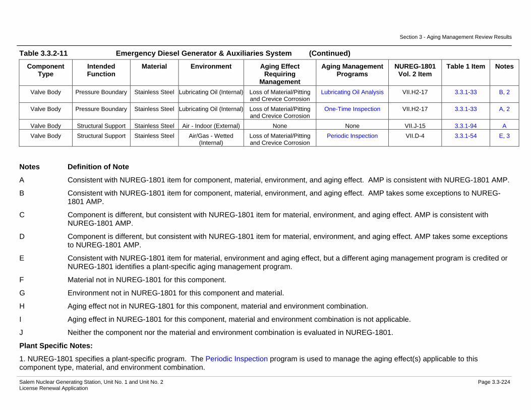
Section 3 - Aging Management Review Results
Salem Nuclear Generating Station, Unit No. 1 and Unit No. 2 Page 3.3-224 License Renewal Application
Table 3.3.2-11 Emergency Diesel Generator & Auxiliaries System (Continued)
Component Type
Intended Function
Material Environment Aging Effect Requiring
Management
Aging Management Programs
NUREG-1801 Vol. 2 Item
Table 1 Item Notes
Valve Body Pressure Boundary Stainless Steel Lubricating Oil (Internal) Loss of Material/Pitting and Crevice Corrosion
Lubricating Oil Analysis VII.H2-17 3.3.1-33 B, 2
Valve Body Pressure Boundary Stainless Steel Lubricating Oil (Internal) Loss of Material/Pitting and Crevice Corrosion
One-Time Inspection VII.H2-17 3.3.1-33 A, 2
Valve Body Structural Support Stainless Steel Air - Indoor (External) None None VII.J-15 3.3.1-94 A Valve Body Structural Support Stainless Steel Air/Gas - Wetted
(Internal) Loss of Material/Pitting and Crevice Corrosion
Periodic Inspection VII.D-4 3.3.1-54 E, 3
Notes Definition of Note
A Consistent with NUREG-1801 item for component, material, environment, and aging effect. AMP is consistent with NUREG-1801 AMP.
B Consistent with NUREG-1801 item for component, material, environment, and aging effect. AMP takes some exceptions to NUREG-1801 AMP.
C Component is different, but consistent with NUREG-1801 item for material, environment, and aging effect. AMP is consistent with NUREG-1801 AMP.
D Component is different, but consistent with NUREG-1801 item for material, environment, and aging effect. AMP takes some exceptions to NUREG-1801 AMP.
E Consistent with NUREG-1801 item for material, environment and aging effect, but a different aging management program is credited or NUREG-1801 identifies a plant-specific aging management program.
F Material not in NUREG-1801 for this component.
G Environment not in NUREG-1801 for this component and material.
H Aging effect not in NUREG-1801 for this component, material and environment combination.
I Aging effect in NUREG-1801 for this component, material and environment combination is not applicable.
J Neither the component nor the material and environment combination is evaluated in NUREG-1801.
Plant Specific Notes:
1. NUREG-1801 specifies a plant-specific program. The Periodic Inspection program is used to manage the aging effect(s) applicable to this component type, material, and environment combination.

Section 3 - Aging Management Review Results
Salem Nuclear Generating Station, Unit No. 1 and Unit No. 2 Page 3.3-225 License Renewal Application
2. Loss of material due to microbiologically-influenced corrosion is not applicable for stainless steel components in a Lubricating Oil environment. Industry and Plant operating experience indicates that the potential for significant degradation of lubricating oil systems due to microbiologically-influenced corrosion is minimal. Lubricating oil systems are maintained to high cleanliness standards by design. Lubricating oil formulations include corrosion inhibitors, and the potential for water and contaminant intrusion is low compared to fuel oil systems; where the bulk storage, delivery and transport of the fuel oil increases the likelihood of moisture and microorganism contamination.
3. The Periodic Inspection program is substituted to manage the aging effect(s) applicable to this component type, material, and environment combination.
4. NUREG-1801 specifies a plant-specific program. The Inspection of Internal Surfaces in Miscellaneous Piping and Ducting Components program is used to manage the aging effect(s) applicable to this component type, material, and environment combination.
5. The aging mechanism of galvanic corrosion for this component, material, and environment is not applicable.
6. The Emergency Diesel Generator Jacket Water Heat Exchanger and Lubricating Oil Heat Exchanger components are evaluated with the Service Water System.
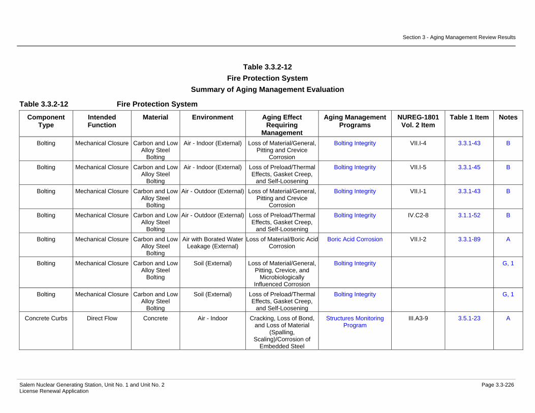
Section 3 - Aging Management Review Results
Salem Nuclear Generating Station, Unit No. 1 and Unit No. 2 Page 3.3-226 License Renewal Application
Table 3.3.2-12 Fire Protection System
Summary of Aging Management Evaluation
Table 3.3.2-12 Fire Protection System
Component Type
Intended Function
Material Environment Aging Effect Requiring
Management
Aging Management Programs
NUREG-1801 Vol. 2 Item
Table 1 Item Notes
Bolting Mechanical Closure Carbon and Low Alloy Steel
Bolting
Air - Indoor (External) Loss of Material/General, Pitting and Crevice
Corrosion
Bolting Integrity VII.I-4 3.3.1-43 B
Bolting Mechanical Closure Carbon and Low Alloy Steel
Bolting
Air - Indoor (External) Loss of Preload/Thermal Effects, Gasket Creep,
and Self-Loosening
Bolting Integrity VII.I-5 3.3.1-45 B
Bolting Mechanical Closure Carbon and Low Alloy Steel
Bolting
Air - Outdoor (External) Loss of Material/General, Pitting and Crevice
Corrosion
Bolting Integrity VII.I-1 3.3.1-43 B
Bolting Mechanical Closure Carbon and Low Alloy Steel
Bolting
Air - Outdoor (External) Loss of Preload/Thermal Effects, Gasket Creep,
and Self-Loosening
Bolting Integrity IV.C2-8 3.1.1-52 B
Bolting Mechanical Closure Carbon and Low Alloy Steel
Bolting
Air with Borated Water Leakage (External)
Loss of Material/Boric Acid Corrosion
Boric Acid Corrosion VII.I-2 3.3.1-89 A
Bolting Mechanical Closure Carbon and Low Alloy Steel
Bolting
Soil (External) Loss of Material/General, Pitting, Crevice, and
Microbiologically Influenced Corrosion
Bolting Integrity G, 1
Bolting Mechanical Closure Carbon and Low Alloy Steel
Bolting
Soil (External) Loss of Preload/Thermal Effects, Gasket Creep,
and Self-Loosening
Bolting Integrity G, 1
Concrete Curbs Direct Flow Concrete Air - Indoor Cracking, Loss of Bond, and Loss of Material
(Spalling, Scaling)/Corrosion of
Embedded Steel
Structures Monitoring Program
III.A3-9 3.5.1-23 A

Section 3 - Aging Management Review Results
Salem Nuclear Generating Station, Unit No. 1 and Unit No. 2 Page 3.3-227 License Renewal Application
Table 3.3.2-12 Fire Protection System (Continued)
Component Type
Intended Function
Material Environment Aging Effect Requiring
Management
Aging Management Programs
NUREG-1801 Vol. 2 Item
Table 1 Item Notes
Concrete Curbs Direct Flow Concrete Air - Indoor Cracks and Distortion/Increased Stress Levels from
Settlement
Structures Monitoring Program
III.A3-3 3.5.1-28 A
Damper Housing Fire Barrier Galvanized Steel Air - Indoor (External) None None VII.J-6 3.3.1-92 C Damper Housing Fire Barrier Galvanized Steel Air/Gas - Wetted
(Internal) Loss of Material/General,
Pitting and Crevice Corrosion
Fire Protection VII.F1-3 3.3.1-72 E, 2
Damper Housing Pressure Boundary Galvanized Steel Air - Indoor (External) None None VII.J-6 3.3.1-92 C Damper Housing Pressure Boundary Galvanized Steel Air/Gas - Wetted
(Internal) Loss of Material/General,
Pitting and Crevice Corrosion
Fire Protection VII.F1-3 3.3.1-72 E, 2
Doors Fire Barrier Carbon Steel Air - Indoor Loss of Material/General Corrosion
Fire Protection VII.I-8 3.3.1-58 E, 2
Doors Fire Barrier Carbon Steel Air - Indoor Loss of Material/Wear Fire Protection VII.G-3 3.3.1-63 B Doors Fire Barrier Carbon Steel Air - Outdoor Loss of Material/General,
Pitting and Crevice Corrosion
Fire Protection VII.G-6 3.3.1-59 E, 2
Doors Fire Barrier Carbon Steel Air - Outdoor Loss of Material/Wear Fire Protection VII.G-4 3.3.1-63 B Doors Fire Barrier Galvanized Steel Air - Indoor Loss of Material/General
Corrosion Fire Protection VII.I-8 3.3.1-58 E, 2
Doors Fire Barrier Galvanized Steel Air - Indoor Loss of Material/Wear Fire Protection VII.G-3 3.3.1-63 B Doors Fire Barrier Galvanized Steel Air - Outdoor Loss of Material/General,
Pitting and Crevice Corrosion
Fire Protection VII.G-6 3.3.1-59 E, 2
Doors Fire Barrier Galvanized Steel Air - Outdoor Loss of Material/Wear Fire Protection VII.G-4 3.3.1-63 B Fire Barriers
(Masonry Walls: Exterior)
Fire Barrier Concrete Block Air - Outdoor Cracking, Loss of Bond, and Loss of Material
(Spalling, Scaling)/Corrosion of
Embedded Steel
Fire Protection III.A3-9 3.5.1-23 E, 3

Section 3 - Aging Management Review Results
Salem Nuclear Generating Station, Unit No. 1 and Unit No. 2 Page 3.3-228 License Renewal Application
Table 3.3.2-12 Fire Protection System (Continued)
Component Type
Intended Function
Material Environment Aging Effect Requiring
Management
Aging Management Programs
NUREG-1801 Vol. 2 Item
Table 1 Item Notes
Fire Barriers (Masonry Walls:
Exterior)
Fire Barrier Concrete Block Air - Outdoor Cracking, Loss of Bond, and Loss of Material
(Spalling, Scaling)/Corrosion of
Embedded Steel
Structures Monitoring Program
III.A3-9 3.5.1-23 C
Fire Barriers (Masonry Walls:
Exterior)
Fire Barrier Concrete Block Air - Outdoor Cracking/Restraint, Shrinkage, Creep, and
Aggressive Environment
Fire Protection III.A3-11 3.5.1-43 E, 3
Fire Barriers (Masonry Walls:
Exterior)
Fire Barrier Concrete Block Air - Outdoor Cracking/Restraint, Shrinkage, Creep, and
Aggressive Environment
Structures Monitoring Program
III.A3-11 3.5.1-43 A, 4
Fire Barriers (Masonry Walls:
Exterior)
Fire Barrier Concrete Block Air - Outdoor Cracks and Distortion/Increased Stress Levels from
Settlement
Fire Protection III.A3-3 3.5.1-28 E, 3
Fire Barriers (Masonry Walls:
Exterior)
Fire Barrier Concrete Block Air - Outdoor Cracks and Distortion/Increased Stress Levels from
Settlement
Structures Monitoring Program
III.A3-3 3.5.1-28 C
Fire Barriers (Masonry Walls:
Exterior)
Fire Barrier Concrete Block Air - Outdoor Loss of Material (Spalling, Scaling) and
Cracking/Freeze-thaw
Fire Protection III.A3-6 3.5.1-26 E, 3
Fire Barriers (Masonry Walls:
Exterior)
Fire Barrier Concrete Block Air - Outdoor Loss of Material (Spalling, Scaling) and
Cracking/Freeze-thaw
Structures Monitoring Program
III.A3-6 3.5.1-26 C
Fire Barriers (Masonry Walls:
Interior)
Fire Barrier Concrete Block Air - Indoor Cracking, Loss of Bond, and Loss of Material
(Spalling, Scaling)/Corrosion of
Embedded Steel
Fire Protection III.A3-9 3.5.1-23 E, 3
Fire Barriers (Masonry Walls:
Interior)
Fire Barrier Concrete Block Air - Indoor Cracking, Loss of Bond, and Loss of Material
(Spalling, Scaling)/Corrosion of
Embedded Steel
Structures Monitoring Program
III.A3-9 3.5.1-23 C
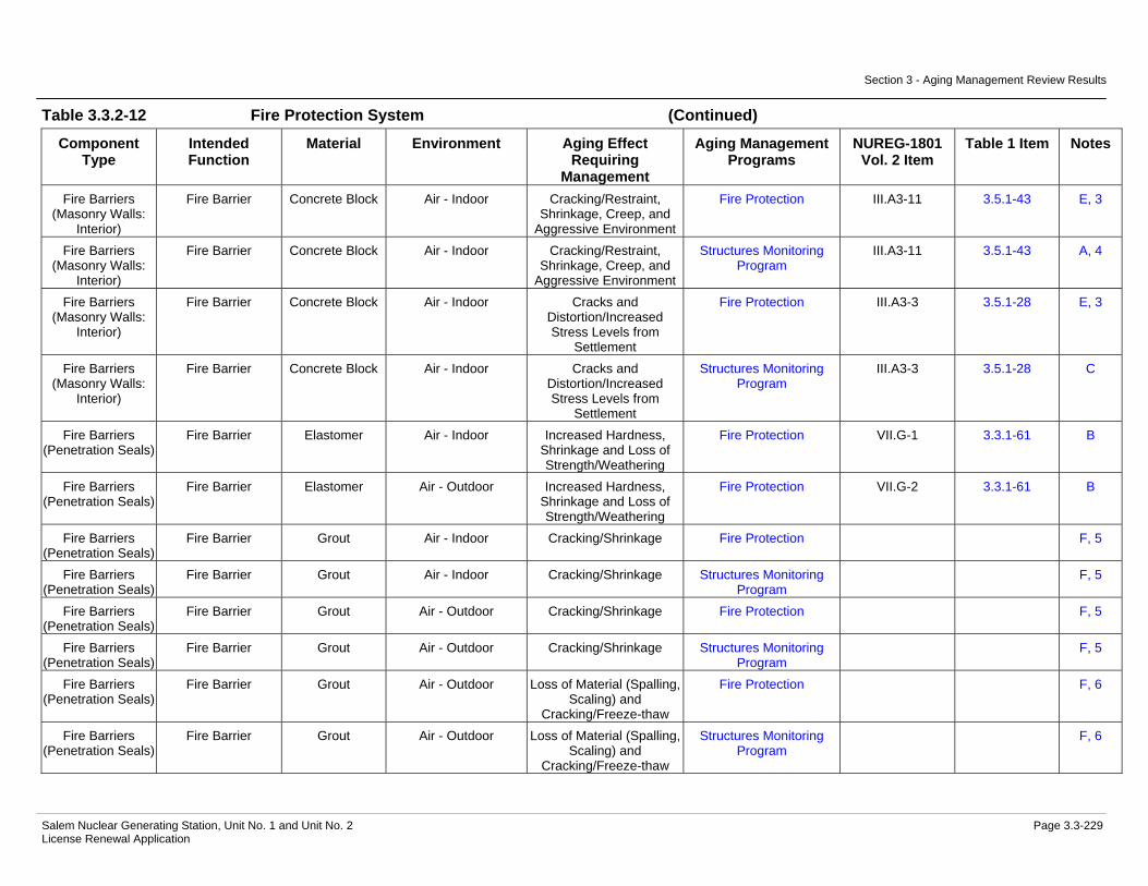
Section 3 - Aging Management Review Results
Salem Nuclear Generating Station, Unit No. 1 and Unit No. 2 Page 3.3-229 License Renewal Application
Table 3.3.2-12 Fire Protection System (Continued)
Component Type
Intended Function
Material Environment Aging Effect Requiring
Management
Aging Management Programs
NUREG-1801 Vol. 2 Item
Table 1 Item Notes
Fire Barriers (Masonry Walls:
Interior)
Fire Barrier Concrete Block Air - Indoor Cracking/Restraint, Shrinkage, Creep, and
Aggressive Environment
Fire Protection III.A3-11 3.5.1-43 E, 3
Fire Barriers (Masonry Walls:
Interior)
Fire Barrier Concrete Block Air - Indoor Cracking/Restraint, Shrinkage, Creep, and
Aggressive Environment
Structures Monitoring Program
III.A3-11 3.5.1-43 A, 4
Fire Barriers (Masonry Walls:
Interior)
Fire Barrier Concrete Block Air - Indoor Cracks and Distortion/Increased Stress Levels from
Settlement
Fire Protection III.A3-3 3.5.1-28 E, 3
Fire Barriers (Masonry Walls:
Interior)
Fire Barrier Concrete Block Air - Indoor Cracks and Distortion/Increased Stress Levels from
Settlement
Structures Monitoring Program
III.A3-3 3.5.1-28 C
Fire Barriers (Penetration Seals)
Fire Barrier Elastomer Air - Indoor Increased Hardness, Shrinkage and Loss of Strength/Weathering
Fire Protection VII.G-1 3.3.1-61 B
Fire Barriers (Penetration Seals)
Fire Barrier Elastomer Air - Outdoor Increased Hardness, Shrinkage and Loss of Strength/Weathering
Fire Protection VII.G-2 3.3.1-61 B
Fire Barriers (Penetration Seals)
Fire Barrier Grout Air - Indoor Cracking/Shrinkage Fire Protection F, 5
Fire Barriers (Penetration Seals)
Fire Barrier Grout Air - Indoor Cracking/Shrinkage Structures Monitoring Program
F, 5
Fire Barriers (Penetration Seals)
Fire Barrier Grout Air - Outdoor Cracking/Shrinkage Fire Protection F, 5
Fire Barriers (Penetration Seals)
Fire Barrier Grout Air - Outdoor Cracking/Shrinkage Structures Monitoring Program
F, 5
Fire Barriers (Penetration Seals)
Fire Barrier Grout Air - Outdoor Loss of Material (Spalling, Scaling) and
Cracking/Freeze-thaw
Fire Protection F, 6
Fire Barriers (Penetration Seals)
Fire Barrier Grout Air - Outdoor Loss of Material (Spalling, Scaling) and
Cracking/Freeze-thaw
Structures Monitoring Program
F, 6

Section 3 - Aging Management Review Results
Salem Nuclear Generating Station, Unit No. 1 and Unit No. 2 Page 3.3-230 License Renewal Application
Table 3.3.2-12 Fire Protection System (Continued)
Component Type
Intended Function
Material Environment Aging Effect Requiring
Management
Aging Management Programs
NUREG-1801 Vol. 2 Item
Table 1 Item Notes
Fire Barriers (Walls, Ceilings,
and Floors)
Fire Barrier Asbestos Air - Indoor (External) None None J, 14
Fire Barriers (Walls, Ceilings,
and Floors)
Fire Barrier Reinforced Concrete
Air - Indoor Cracking, Loss of Bond, and Loss of Material
(Spalling, Scaling)/Corrosion of
Embedded Steel
Structures Monitoring Program
III.A3-9 3.5.1-23 A
Fire Barriers (Walls, Ceilings,
and Floors)
Fire Barrier Reinforced Concrete
Air - Indoor Cracks and Distortion/Increased Stress Levels from
Settlement
Fire Protection III.A3-3 3.5.1-28 E, 3
Fire Barriers (Walls, Ceilings,
and Floors)
Fire Barrier Reinforced Concrete
Air - Indoor Cracks and Distortion/Increased Stress Levels from
Settlement
Structures Monitoring Program
III.A3-3 3.5.1-28 A
Fire Barriers (Walls, Ceilings,
and Floors)
Fire Barrier Reinforced Concrete
Air - Indoor Loss of Materia/Corrosion of Embedded Steel
Fire Protection VII.G-29 3.3.1-67 B
Fire Barriers (Walls, Ceilings,
and Floors)
Fire Barrier Reinforced Concrete
Air - Indoor Loss of Materia/Corrosion of Embedded Steel
Structures Monitoring Program
VII.G-29 3.3.1-67 A
Fire Barriers (Walls, Ceilings,
and Floors)
Fire Barrier Reinforced Concrete
Air - Outdoor Concrete Cracking and Spalling/Freeze-thaw
Fire Protection VII.G-30 3.3.1-66 B, 7
Fire Barriers (Walls, Ceilings,
and Floors)
Fire Barrier Reinforced Concrete
Air - Outdoor Concrete Cracking and Spalling/Freeze-thaw
Structures Monitoring Program
VII.G-30 3.3.1-66 A, 7
Fire Barriers (Walls, Ceilings,
and Floors)
Fire Barrier Reinforced Concrete
Air - Outdoor Cracking, Loss of Bond, and Loss of Material
(Spalling, Scaling)/Corrosion of
Embedded Steel
Structures Monitoring Program
III.A3-9 3.5.1-23 A

Section 3 - Aging Management Review Results
Salem Nuclear Generating Station, Unit No. 1 and Unit No. 2 Page 3.3-231 License Renewal Application
Table 3.3.2-12 Fire Protection System (Continued)
Component Type
Intended Function
Material Environment Aging Effect Requiring
Management
Aging Management Programs
NUREG-1801 Vol. 2 Item
Table 1 Item Notes
Fire Barriers (Walls, Ceilings,
and Floors)
Fire Barrier Reinforced Concrete
Air - Outdoor Cracks and Distortion/Increased Stress Levels from
Settlement
Fire Protection III.A3-3 3.5.1-28 E, 3
Fire Barriers (Walls, Ceilings,
and Floors)
Fire Barrier Reinforced Concrete
Air - Outdoor Cracks and Distortion/Increased Stress Levels from
Settlement
Structures Monitoring Program
III.A3-3 3.5.1-28 A
Fire Barriers (Walls, Ceilings,
and Floors)
Fire Barrier Reinforced Concrete
Air - Outdoor Loss of Materia/Corrosion of Embedded Steel
Fire Protection VII.G-31 3.3.1-67 B
Fire Barriers (Walls, Ceilings,
and Floors)
Fire Barrier Reinforced Concrete
Air - Outdoor Loss of Materia/Corrosion of Embedded Steel
Structures Monitoring Program
VII.G-31 3.3.1-67 A
Fire Barriers (Wraps)
Fire Barrier Aluminum Air - Indoor None None V.F-2 3.2.1-50 C
Fire Barriers (Wraps)
Fire Barrier Aluminum Air with Borated Water Leakage (External)
Loss of Material/Boric Acid Corrosion
Boric Acid Corrosion VII.E1-10 3.3.1-88 C
Fire Barriers (Wraps)
Fire Barrier Fiberglass Cloth Air - Indoor None None J, 15
Fire Barriers (Wraps)
Fire Barrier Fiberglass Cloth Air with Borated Water Leakage (External)
None None J, 15
Fire Hydrant Pressure Boundary Gray Cast Iron Air - Outdoor (External) Loss of Material/General, Pitting and Crevice
Corrosion
External Surfaces Monitoring
VII.H1-8 3.3.1-60 A
Fire Hydrant Pressure Boundary Gray Cast Iron Air - Outdoor (External) Loss of Material/General, Pitting and Crevice
Corrosion
Fire Water System VII.H1-8 3.3.1-60 E, 8
Fire Hydrant Pressure Boundary Gray Cast Iron Raw Water (Internal) Loss of Material/General, Pitting, Crevice, and
Microbiologically Influenced Corrosion, and
Fouling
Fire Water System VII.G-24 3.3.1-68 A
Fire Hydrant Pressure Boundary Gray Cast Iron Raw Water (Internal) Loss of Material/Selective Leaching
Selective Leaching of Materials
VII.G-14 3.3.1-85 A

Section 3 - Aging Management Review Results
Salem Nuclear Generating Station, Unit No. 1 and Unit No. 2 Page 3.3-232 License Renewal Application
Table 3.3.2-12 Fire Protection System (Continued)
Component Type
Intended Function
Material Environment Aging Effect Requiring
Management
Aging Management Programs
NUREG-1801 Vol. 2 Item
Table 1 Item Notes
Fire Hydrant Pressure Boundary Gray Cast Iron Soil (External) Loss of Material/General, Pitting, Crevice, and
Microbiologically Influenced Corrosion
Buried Piping Inspection VII.G-25 3.3.1-19 A
Fire Hydrant Pressure Boundary Gray Cast Iron Soil (External) Loss of Material/Selective Leaching
Selective Leaching of Materials
VII.G-15 3.3.1-85 A
Flow Alarm Switch Pressure Boundary Gray Cast Iron Air - Indoor (External) Loss of Material/General Corrosion
External Surfaces Monitoring
VII.D-3 3.3.1-57 A
Flow Alarm Switch Pressure Boundary Gray Cast Iron Air - Indoor (External) Loss of Material/General Corrosion
Fire Water System VII.D-3 3.3.1-57 E, 8
Flow Alarm Switch Pressure Boundary Gray Cast Iron Air with Borated Water Leakage (External)
Loss of Material/Boric Acid Corrosion
Boric Acid Corrosion VII.I-10 3.3.1-89 A
Flow Alarm Switch Pressure Boundary Gray Cast Iron Raw Water (Internal) Loss of Material/General, Pitting, Crevice, and
Microbiologically Influenced Corrosion, and
Fouling
Fire Water System VII.G-24 3.3.1-68 A
Flow Alarm Switch Pressure Boundary Gray Cast Iron Raw Water (Internal) Loss of Material/Selective Leaching
Selective Leaching of Materials
VII.G-14 3.3.1-85 A
Flow Element (F-3423)
Pressure Boundary Stainless Steel Air - Indoor (External) None None VII.J-15 3.3.1-94 A
Flow Element (F-3423)
Pressure Boundary Stainless Steel Raw Water (Internal) Loss of Material/Pitting, Crevice, and
Microbiologically Influenced Corrosion, and
Fouling
Fire Water System VIII.E-3 3.4.1-33 E, 9
Gas Bottles (Halon) Pressure Boundary Carbon Steel Air - Indoor (External) Loss of Material/General Corrosion
External Surfaces Monitoring
VII.D-3 3.3.1-57 C
Gas Bottles (Halon) Pressure Boundary Carbon Steel Air - Indoor (External) Loss of Material/General Corrosion
Fire Protection VII.D-3 3.3.1-57 E, 10
Gas Bottles (Halon) Pressure Boundary Carbon Steel Air/Gas - Dry (Internal) None None VII.J-23 3.3.1-97 C

Section 3 - Aging Management Review Results
Salem Nuclear Generating Station, Unit No. 1 and Unit No. 2 Page 3.3-233 License Renewal Application
Table 3.3.2-12 Fire Protection System (Continued)
Component Type
Intended Function
Material Environment Aging Effect Requiring
Management
Aging Management Programs
NUREG-1801 Vol. 2 Item
Table 1 Item Notes
Heat Exchanger Components (Fresh Water Storage Tank)
Pressure Boundary Stainless Steel (Shellside
Components)
Air - Indoor (External) None None VII.J-15 3.3.1-94 C
Heat Exchanger Components (Fresh Water Storage Tank)
Pressure Boundary Stainless Steel (Shellside
Components)
Raw Water (Internal) Loss of Material/Pitting, Crevice, and
Microbiologically Influenced Corrosion, and
Fouling
Fire Water System VIII.E-3 3.4.1-33 E, 9
Heat Exchanger Components (Fresh Water Storage Tank)
Pressure Boundary Stainless Steel (Tube Sheet)
Closed Cycle Cooling Water (Internal) > 140 F
Cracking/Stress Corrosion Cracking
Closed-Cycle Cooling Water System
VII.E3-2 3.3.1-46 B
Heat Exchanger Components (Fresh Water Storage Tank)
Pressure Boundary Stainless Steel (Tube Sheet)
Closed Cycle Cooling Water (Internal) > 140 F
Loss of Material/Pitting and Crevice Corrosion
Closed-Cycle Cooling Water System
VII.C2-10 3.3.1-50 D
Heat Exchanger Components (Fresh Water Storage Tank)
Pressure Boundary Stainless Steel (Tube Sheet)
Raw Water (Internal) Loss of Material/Pitting, Crevice, and
Microbiologically Influenced Corrosion, and
Fouling
Fire Water System VIII.E-3 3.4.1-33 E, 9
Heat Exchanger Components (Fresh Water Storage Tank)
Pressure Boundary Stainless Steel (Tube Side
Components)
Air - Indoor (External) None None VII.J-15 3.3.1-94 C
Heat Exchanger Components (Fresh Water Storage Tank)
Pressure Boundary Stainless Steel (Tube Side
Components)
Closed Cycle Cooling Water (Internal) > 140 F
Cracking/Stress Corrosion Cracking
Closed-Cycle Cooling Water System
VII.E3-2 3.3.1-46 B
Heat Exchanger Components (Fresh Water Storage Tank)
Pressure Boundary Stainless Steel (Tube Side
Components)
Closed Cycle Cooling Water (Internal) > 140 F
Loss of Material/Pitting and Crevice Corrosion
Closed-Cycle Cooling Water System
VII.C2-10 3.3.1-50 D