Safety Manual 24-FEB-2012
274
“DRAFT ROAD TRAFFIC AND WORK ZONE SAFETY MANUAL” For “Comments of experts and stake holders” ( To be sent to Road Safety Cell of NHAI by July 2012 end)
Transcript of Safety Manual 24-FEB-2012

“DRAFT ROAD TRAFFIC AND WORK ZONE SAFETY MANUAL”
For
“Comments of experts and stake holders”
( To be sent to Road Safety Cell of NHAI by July 2012 end)

ROAD TRAFFIC AND WORK ZONE SAFETY MANUAL
Submitted to
NATIONAL HIGHWAY AUTHORITY OF INDIA
Submitted by
INDIAN INSTITUTE OF TECHNOLOGY DELHI
February 2012

i
TABLE OF CONTENTS
TABLE OF CONTENTS ..................................................................................................... i
LIST OF TABLES .............................................................................................................. ix
LIST OF FIGURES ............................................................................................................. x
1. Introduction ................................................................................................................ 13
1.1 Introduction and Guidance to Users .......................................................................... 13
1.1.1 Why this manual? .............................................................................................. 13
1.1.2 How was this manual developed? ...................................................................... 13
1.1.3 Who are the intended users? .............................................................................. 14
1.1.4 Structure and content ......................................................................................... 14
1.1.5 Adapting the content to a local context.............................................................. 15
1.2 Legislation ................................................................................................................. 16
1.2.1 Laws and Rules related to Health, Safety and Welfare of construction workers …………………………………………………………………………………16
1.3 Safety, Health and Environment Management ......................................................... 18
1.3.1 Safety, Health and Environment (SHE) Policy ................................................. 18
1.3.2 Roles & Responsibilities of Organizations ........................................................ 20
1.3.2.1 NHAI .......................................................................................................... 20
1.3.3 Consultants ......................................................................................................... 20
1.3.3.1 Contractor ................................................................................................... 22
2. Safety Management Issues ........................................................................................ 23
2.1 Investigation, Reporting, Analysis and Record Keeping of Incidents ...................... 23
2.1.1 Introduction ........................................................................................................ 23
2.1.2 The need to look at the entire system ................................................................. 24
2.1.3 Why collect data and build evidence? ............................................................... 24
2.1.4 Data collection and analysis PRINCIPLES ....................................................... 25
2.1.5 Data issues and concerns ................................................................................... 25
2.1.6 Indicators............................................................................................................ 27
2.1.7 Underreporting ................................................................................................... 27
2.1.8 Investigation and data collection procedures ..................................................... 28

ii
2.1.9 Forms for recording events ................................................................................ 28
2.1.10 Data Analysis and safety countermeasures ........................................................ 29
2.1.11 Basic principles .................................................................................................. 29
2.1.12 Data analysis for worker injuries ....................................................................... 30
2.2 Emergency Response Plan ........................................................................................ 31
2.3 Health of Workers ..................................................................................................... 32
2.3.1 a) Pre-employment health check up ................................................................... 32
2.3.2 b) Records: ......................................................................................................... 32
2.3.3 c) Provision of facilities ..................................................................................... 33
2.3.4 d) Provision of medical staff: ............................................................................ 35
2.4 Training ..................................................................................................................... 35
2.5 Training Facility ........................................................................................................ 35
2.6 Tool Box Meeting ..................................................................................................... 36
2.7 Safety Promotion ....................................................................................................... 37
2.8 Auditing ..................................................................................................................... 37
2.9 Hazard Identification, Risk Assessment and Control Measures ............................... 39
ANNEXURE 2.1.................................................................................................................. 41
ANNEXURE 2.2.................................................................................................................. 46
3. Traffic Safety .............................................................................................................. 48
3.1 Preamble .................................................................................................................... 48
3.2 Scope ......................................................................................................................... 49
3.3 Objective ................................................................................................................... 49
3.4 Process ....................................................................................................................... 50
3.5 Definitions ................................................................................................................. 53
3.6 Guiding Principles ..................................................................................................... 53
3.7 Phases of Traffic Control .......................................................................................... 54
3.8 Components of Construction Zone ........................................................................... 54
3.9 Traffic Control Zone ................................................................................................. 55
3.10 Advance Warning Zone ......................................................................................... 57
3.11 Transition Zone...................................................................................................... 57

iii
3.12. Working Zone ........................................................................................................ 58
3.12.1 Components of Working Zone .............................................................................. 59
3.13. Termination Zone .................................................................................................. 61
3.14. Tapers .................................................................................................................... 61
3.14.1 Designing of Taper Length for SHORT-DURATION Work ................................ 64
3.14.2 Designing of Taper Length for SHORT DURATION and LONG DURATION Work ……………………………………………………………………………………64
3.14.3 Designing of Taper Length for LONG DURATION Work .................................. 66
3.15 Other Aspects ........................................................................................................ 67
3.16 Highway passing through villages and small towns .............................................. 69
3.17 Traffic Control Devices ......................................................................................... 69
3.17.1 Signs ...................................................................................................................... 70
3.17.1.1 Sign Placement ................................................................................................... 71
3.17.1.2 Mandatory/Regulatory Signs ............................................................................. 72
3.17.1.3 Cautionary/Warning Signs ................................................................................. 76
3.17.1.4 Informatory/Guide Signs ................................................................................... 80
3.17.2 Delineation and Channelizing Devices .................................................................. 80
3.17.2.1 Traffic Cones ..................................................................................................... 81
3.17.2.1.1 Cone Design ................................................................................................... 83
3.17.2.1.2 Retroreflectivity specs for the sleeve ............................................................. 83
3.17.2.1.3 Flexibility specs .............................................................................................. 84
3.17.2.1.4 Cone Application ............................................................................................ 84
3.17.2.2 Traffic Cylinders/Spring Posts ........................................................................... 84
3.17.2.3 Drums ................................................................................................................. 85
3.17.2.4 Water-Filled Barricades ..................................................................................... 86
3.17.3 Barricades .............................................................................................................. 89
3.17.3.1 Plastic Mesh Fencing ......................................................................................... 92
3.17.3.2 Plastic Barricades ............................................................................................... 93
3.17.4 Hand Paddles ......................................................................................................... 94
3.17.5 Roll Up Signs: ....................................................................................................... 98
3.17.6 Marking ................................................................................................................. 99

iv
3.18 Traffic Management Practices ............................................................................. 101
3.18.1 Introduction ......................................................................................................... 101
3.18.2 Basic Layout ........................................................................................................ 103
3.18.3 Variations on the Basic Layout ........................................................................... 106
3.18.4 Portable Traffic Signals ....................................................................................... 112
3.18.5 Works on Footways - Alternative Way for Pedestrians ...................................... 113
3.18.6 Pedestrian Safety ................................................................................................. 113
3.18.7 Pedestrian Barriers ............................................................................................... 114
3.18.8 Barriers for Visually Impaired ............................................................................. 114
3.18.9 Deep Excavations ................................................................................................ 114
3.18.10 Safety Zones..................................................................................................... 115
3.18.11 Pedestrian Crossings ........................................................................................ 115
3.18.12 Works at Junctions ........................................................................................... 115
3.18.13 Works on Construction of Additional Carriageway ........................................ 117
3.18.13.1 The Central line of the road shifted (eccentric widening) ............................ 117
3.18.13.2 No shift in central line of the road (co-centric widening) ............................ 117
3.19 Divided Carriageway Roads ................................................................................ 121
3.20 Expressway and High Speed Divided Carriageway Roads ................................. 129
3.20.1 Four -lane divided carriageways-right lane closure ............................................ 133
3.20.2 Four -lane divided carriageways-left lane closure ............................................... 133
3.20.3 Four-lane divided carriageways - carriageway closure with diversion to opposite carriageway ........................................................................................................................ 133
3.21 Six-lane Divided Carriageways and Expressways .............................................. 134
3.21.1 Left and centre lanes closed ................................................................................. 134
3.21.2 Right and centre lanes closed .............................................................................. 134
3.21.3 Segregated contraflow with buffer zones (Primary hard shoulders used) ........... 140
3.21.4 Segregated contraflow with buffer zones (Both hard shoulders used) ................ 140
3.22 Detour via Secondary Network ........................................................................... 142
3.23 Temporary Diversions ......................................................................................... 148
3.24 Speed Control ...................................................................................................... 151
3.25 Alternatives for Different work zone Situations for Traffic Management .......... 154

v
3.26 DO’S AND DON’TS........................................................................................... 156
3.27 PENALTIES ........................................................................................................ 158
BOQ items for 2 Lane Highway ........................................................................................ 160
BOQ items for 4 Lane Highway ........................................................................................ 163
BOQ items for 6 Lane Highway ........................................................................................ 166
4. Safety in Road Construction Works ...................................................................... 169
4.1 General .................................................................................................................... 169
Methodology and Sequence of Work .................................................................................. 169
4.2 Safety aspects in road construction: general ........................................................... 171
4.3 Site Clearance/Borrow Pits/Quarrying .................................................................... 174
Site Clearance .................................................................................................................... 174
Quarry Operations ............................................................................................................. 174
Substances Hazardous to Health ....................................................................................... 174
Use of Nuclear Gauges ...................................................................................................... 174
4.4 Earth work ............................................................................................................... 174
4.5 Granular Sub-Base/Base courses ............................................................................ 177
4.6 Surface courses ........................................................................................................ 178
Cement Concrete – Surfaces and Dry Lean Cement Concrete (DLC) Sub-base ............... 178
4.7 References: .............................................................................................................. 187
5. Temporary Structures Safety ................................................................................. 188
5.1 Introduction .................................................................................................................. 188
5.2 Definition of Temporary Structures Related Terms ................................................ 188
5.3 Guidelines for the preparation of Formwork Schemes (Plans) ............................... 189
5.3.1 Reporting of dangerous occurrences ................................................................ 189
5.3.2 Frequency of inspection ................................................................................... 190
5.4 Formwork Arrangement for Typical Structural Elements ...................................... 190
5.4.1 Wall formwork ................................................................................................. 190
5.4.2 Column Formwork ........................................................................................... 192
5.4.3 Well/Caisson formwork ................................................................................... 193
5.4.4 Pier and Pier Cap Formwork ............................................................................ 193

vi
5.4.5 Girder and Deck Slab Formwork ..................................................................... 194
5.4.6 Formwork for Edge beam/Parapet ................................................................... 197
5.5 Work at height ......................................................................................................... 198
5.5.1 Inspection of places of work at height ............................................................. 199
5.5.2 Duties of persons at work ................................................................................ 199
5.5.3 Requirements for existing places of work and means of access or egress at height ………………………………………………………………………………..199
5.5.4 Requirements for guardrails, toe-boards, barriers and similar collective means of protection ................................................................................................................... 199
5.6 Working Platforms .................................................................................................. 199
5.6.1 Requirements for all Working Platforms ......................................................... 200
5.7 Scaffolding .............................................................................................................. 200
5.7.1 Safety Provisions in Building the Scaffolds .................................................... 200
5.7.2 Additional requirements for scaffolding .......................................................... 201
5.8 Ladders .................................................................................................................... 202
5.9 Launching Operation ............................................................................................... 202
5.10 Batching Plant / Casting Yard ............................................................................. 202
5.11 Work over water .................................................................................................. 203
5.11.1 Rescue Equipment ........................................................................................... 203
5.11.2 Rescue Boats .................................................................................................... 203
5.11.3 Standby Person................................................................................................. 203
5.12 Checklists (Do’s and Don’ts) .............................................................................. 204
5.13 Penalties for Non Compliance ............................................................................. 208
6. Worker and Work Zone Safety ............................................................................. 210
6.1 Material Handling ................................................................................................. 211
6.1.1 Hazardous materials handling, storage, and use .............................................. 211
6.1.2 Manual material handling ................................................................................ 212
6.1.3 Mechanical material handling .......................................................................... 212
6.1.4 Handling of petroleum products ...................................................................... 216
6.1.5 Spill control management: ............................................................................... 217
6.2 House Keeping ........................................................................................................ 218
vii
6.3 Noise........................................................................................................................ 219
6.4 Illumination ............................................................................................................. 222
6.5 Dust and Emission Control ..................................................................................... 222
6.6 Personal Protective Equipment and Other Safety Appliances ................................ 224
6.7 Working at Height ................................................................................................... 226
6.7.1 Use of Scaffolds ............................................................................................... 227
6.7.2 Use of Ladders ................................................................................................. 227
6.7.3 Fencing for work at a height ............................................................................ 228
7. Electrical and Mechanical Safety ........................................................................... 229
7.1 Electrical and Mechanical Safety ............................................................................ 229
7.1.1 Equipment Fitness Certificate .......................................................................... 229
7.1.2 Hand and Portable Power Tool ........................................................................ 229
7.1.2.1 General...................................................................................................... 229
7.1.2.2 Hand tools ................................................................................................. 230
7.1.2.3 Portable Power tools ................................................................................. 230
7.1.3 Safety in Gas Cutting and Welding ................................................................. 232
7.1.4 Safety in Electricity Generation, Distribution, and use ................................... 234
7.2 Construction Plants Safety ...................................................................................... 240
7.2.1 Maintenance and Work Permit System............................................................ 240
7.3 Fire Safety ............................................................................................................... 241
APPENDIX -I .................................................................................................................... 242
i. Checklists for Traffic Management Arrangements .................................................... 242
ii. Compliance Calculations ........................................................................................... 244
a) Document compliance ......................................................................................... 244
b) Field compliance.................................................................................................. 244
iii. Taper Length calculations ....................................................................................... 245
iv. Modules (for calculation of traffic signs/delineation devices) for 100m Work Zone for TMPs .................................................................................................................................. 250
4.1 Figure titled: “Traffic control by Give and Take System” ...................................... 250
4.2 Figure Titled: “Traffic Control by STOP/GO Board” ................................................. 251
4.3 Figure titled: “Basic Layout” ....................................................................................... 252

viii
4.4 Figure titled: “Traffic Control by portable Traffic Signals” ....................................... 253
4.7 Figure titled: “Layout of signs for 4-laning with shift in centre line” ......................... 255
4.8 Figure titled: “Layout of signs and control devices for change in carriageway usage”............................................................................................................................................ 256
4.9 Figure titled: “Traffic control by Priority signs” ......................................................... 257
4.10 Figure titled: “Co-centric widening: Stage I – construction of new lanes” .............. 258
4.11 Figure titled: “Co-centric widening: Stage II – Strengthening of existing carriageway and median construction” .................................................................................................. 259
4.12 Figure titled: “Co-centric widening: Stage III – Shifting of work zone” ................. 260
4.13 Figure titled: “Works on dual carriageway roads left hand lane closed for Traffic” 261
4.14 Figure titled: “Works on dual carriageway roads right hand lane closed for Traffic”............................................................................................................................................ 262
4.15 Figure titled: “Works in centre of Two Lane Single Carriageway” ......................... 263
4.16 Figure titled: “Expressway without hard shoulder. Lane adjacent to median closed for Traffic” ............................................................................................................................... 264
4.17 Figure titled: “Dual Two Lane Expressway having centre flow with buffer zone between opposing flows. Either hard shoulder used” ........................................................ 265
4.18 Figure titled: “Dual Three lane Expressway with left and centre lane closed” ......... 266
4.19 Figure titled: “Dual Three lanes Expressway with right and centre lane closed on one carriageway” ...................................................................................................................... 267
4.20 Figure titled: “Dual Three lanes Expressway having segregated Contra flow with buffer zones – primary hard shoulders used” .................................................................... 268
4.21 Figure titled: “Works at Road Junctions” ................................................................. 269
4.22 Figure titled: “Works on or near the far side of a junction” ..................................... 270
4.23 Figure titled: “Layout of signs and Control Devices for Road closed with a Diversion” .......................................................................................................................... 272

ix
LIST OF TABLES
Table 1-1 Contents of the SHE Plan for guidance ................................................................... 18
Table 2-1 Examples of commonly used indicators of the road traffic injury problem ............ 26
Table 3-1 Recommended Ratio for Taper Length (N) ............................................................. 63
Table 3-2 Summary of Taper Length calculated ..................................................................... 63
Table 3-3: Recommended Lengths of Traffic Control Zones .................................................. 68
Table 3-4: Format of Legends on Shoulder Mounted Signs* .................................................. 72
Table 3-5 Minimum Sightline Distances and the Minimum Size of the Signs ....................... 76
Table 3-6 Acceptable Limits for Size of Letters and Visibility Distance* .............................. 78
Table 3-7 Height of Cones, Cylinders and Drums according to Class of Sheeting ................. 81
Table 3-8 Summary of Delineation and Channelizing Devices ............................................... 88
Table 3-9: Barricade Characteristics ........................................................................................ 91
Table 3-10 Summary of Barricades ......................................................................................... 94
Table 3-11: Size and Siting Distance: Detail of Signs and Cones ......................................... 101
Table 3-12: Buffer Zone Safety Clearances* ......................................................................... 102
Table 3-13: Maximum Traffic Flows for Length of Site .................................................. 112
Table 3-14 : Signage Requirements ....................................................................................... 122
Table 3-15 : Penalty for non compliance of provisions in Traffic Management and Safety . 159
Table 4-1Equipment/Processes related various road construction aspects .................... 173
Table 4-2 Penalties for Road construction works of NHAI (The penalties and deductible amounts are indicative and the actual amounts needs to be decided by NHAI) .................... 181
Table 4-3 Do’s and Don’ts for general construction safety ................................................... 183
Table 5-1 Penalty for non-compliance of provisions in structural safety .............................. 209

x
LIST OF FIGURES
Figure 2-1 Four steps in dealing safety issues ......................................................................... 23
Figure 3-1: Traffic Management Process for Construction Zones .......................................... 52
Figure 3-2: Elements of Traffic Control Zone ......................................................................... 56
Figure 3-3: Components of Working Zone .............................................................................. 60
Figure 3-4: Types of Tapers and Buffer Spaces ...................................................................... 62
Figure 3-5: Taper for Short duration work .............................................................................. 64
Figure 3-6: Taper for Short and Long duration work .............................................................. 65
Figure 3-7: Taper curve for short and long duration work ...................................................... 65
Figure 3-8: Taper for extended Long Duration work and Complicated Traffic diversion ...... 66
Figure 3-9: Taper Curve for extended Long Duration work and Complicated Traffic Diversion .................................................................................................................................. 67
Figure 3-10: Regulatory Signs ................................................................................................. 74
Figure 3-11: Regulatory Signs (contd.) ................................................................................... 75
Figure 3-12: Other Regulatory Signs used in construction zones............................................ 75
Figure 3-13: Warning Sign Details .......................................................................................... 77
Figure 3-14: Warning signs ................................................................................................... 79
Figure 3-15: Traffic Warning Sign .......................................................................................... 80
Figure 3-16: Placement of Traffic Cone .................................................................................. 83
Figure 3-17: Placement of Spring Post .................................................................................... 85
Figure 3-18: Cone, Spring Post and Drum............................................................................... 86
Figure 3-19: Water-filled barricades ........................................................................................ 87
Figure 3-20: Placement of Water filled barricade .................................................................... 88
Figure 3-21: Barricade specifications ...................................................................................... 90
Figure 3-22: Type IV Barricade ............................................................................................... 92
Figure 3-23: Example of plastic mesh fence, fence post and ties ............................................ 93
Figure 3-24: Example of plastic barricade posts and double ................................................... 93
Figure 3-25: Warning sign on hand paddles ............................................................................ 96
Figure 3-26: Marshalling Torch ........................................................................................... 96
Figure 3-27: Temporary Installation of Signs on Maintenance Vehicle, Rollup Stand and Barricade .................................................................................................................................. 97

xi
Figure 3-28: Detail of Marking and Placement of cones ....................................................... 100
Figure 3-29: Basic Layout ................................................................................................... 107
Figure 3-30: Traffic control by Give and Take system .................................................... 108
Figure 3-31: Traffic control by Priority Signs ....................................................................... 109
Figure 3-32: Traffic control by STOP /GO Board ............................................................ 110
Figure 3-33: Traffic Control by portable traffic signals ........................................................ 111
Figure 3-34: Works on footways ........................................................................................... 116
Figure 3-35: Works at road junctions .................................................................................... 119
Figure 3-36: Works on or near the far side of a junction ...................................................... 120
Figure 3-37: Layout of signs for 4-laning with shift in centre line ........................................ 123
Figure 3-38: Layout of signs and control devices for change in carriageway usage ............. 124
Figure 3-39: Co-centric widening: Stage I – construction of new lanes ................................ 125
Figure 3-40: Co-centric widening: Stage II – strengthening of existing carriageway and median construction ............................................................................................................... 126
Figure 3-41: Co-centric widening: Stage III – shifting of work zone .................................... 127
Figure 3-42: Works on dual carriageway roads right hand lane closed for traffic ................ 130
Figure 3-43: Works on dual carriageway roads, left hand lane closed for traffic ................. 131
Figure 3-44: Works in centre of 2-lane single carriageway ............................................. 132
Figure 3-45: Detail of Traffic cones (1) ................................................................................. 135
Figure 3-46: Detail of Traffic cones (2) ................................................................................. 136
Figure 3-47: Detail of Traffic cones (3) ................................................................................. 137
Figure 3-48: Expressway without hard shoulder. Lane adjacent to median closed for traffic................................................................................................................................................ 138
Figure 3-49: Expressway with hard shoulder. Left lane closed for traffic ............................ 139
Figure 3-50: Dual two-lane expressway having centre flow with buffer zone between opposite flows. Either hard shoulder used ............................................................................. 141
Figure 3-51: Dual three lane expressway with left and centre lane closed ............................ 144
Figure 3-52: Dual three lane expressway with right and centre lane closed on one carriageway................................................................................................................................................ 145
Figure 3-53: Dual three lane expressway having segregated contraflow with buffer zones - primary hard shoulders used .................................................................................................. 146

xii
Figure 3-54: Dual three lane expressway having segregated contra flow with buffer zones - both hard shoulders used ........................................................................................................ 147
Figure 3-55: Layout of signs for road closed with detour ..................................................... 149
Figure 3-56: Layout of signs and control devices for road closed with diversion ................. 150
Figure 3-57: Placement of Rumble strips in work zone area ................................................. 152
Figure 3-58: Details of Rumble Strips ................................................................................... 153
Figure 4-1 Road construction safety process ......................................................................... 170
Figure 5-1 : Typical wall formwork ....................................................................................... 191
Figure 5-2 (a) Column form work (b) Column form work showing access arrangements ... 192
Figure 5-3 Formwork arrangement of pier for first lift and subsequent lifts ......................... 193
Figure 5-4 Sectional view of formwork for pier cap ............................................................. 194
Figure 5-6 Section BB (Temporary arrangement for Girder restraining) .............................. 195
Figure 5-7: Edge beam formwork .......................................................................................... 198

National Highway Authority of India
13
1. Introduction
1.1 Introduction and Guidance to Users
1.1.1 Why this manual?
According to official statistics (National Crime Records Bureau), 118, 239 people were killed in road traffic crashes in India in 2008. The situation in India has worsened in recent years. Traffic fatalities increased by about 5% per year from 1980 to 2000, and since then have increased by about 8% per year in recent years. This is attributable partly to an increase in the number of vehicles on the road, and partly to the absence of a coordinated official policy to control the problem. The fatality rate has increased from 36 fatalities per million persons in 1980 to 103 fatalities per million persons in 2008. Many of these traffic injuries and deaths take place in constructions zones on all roads and highways. In addition, a significant number of workers associated with construction and maintenance of roads also get injured and killed every year. This increasing trend in injuries and fatalities has been recognised as a public health problem of significance by the authorities and public at large.
There is an urgent need to train practitioners and policy-makers in the scientific approach to injury prevention. There needs to be a cadre of professionals working from a shared understanding of the magnitude of the problem of road traffic and work injuries, risk factors and the value of implementing evidence-based strategies. This underscores the need for persons working at all levels in road construction and maintenance to be equipped with appropriate knowledge and skills derived from empirical evidence and professional wisdom. Intervention programmes seeking to prevent injuries need to address the problem of capacity in different sectors. This manual attempts to address the problem of capacity for injury prevention by providing guidance to professionals managing road construction activity
1.1.2 How was this manual developed?
NHAI had engaged Indian Institute of Technology Delhi (IITD) for undertaking safety audit of contract packages under the Lucknow Muzaffarpur National Highway Project (LMNHP), World Bank funded 4-laning of NH-28 between Lucknow and Muzaffarpur. IITD team comprised of experts from the following disciplines:
• Contract specialist
• Traffic management and safety
• Construction safety,
• Structural safety,
• Mechanical, Electrical, and Fire Safety, and
• Workers and work zone safety,

National Highway Authority of India
14
• OSHA Specialist
The team visited all construction zones, conducted safety audits, and had discussions with all stake holders. The technical, legal and social issues were discussed in detail with NHAI and World Bank authorities and at workshops organised for this purpose. All the relevant information was gathered and a draft of the manual was prepared, peer reviewed, and revised, ultimately being published in the present form. It is envisaged that the manual will be further refined in the light of experience in its use.
1.1.3 Who are the intended users?
This manual is designed for a broad inter-disciplinary audience consisting of people involved in preventing work and road traffic injuries at work zones on roads and highways. This group includes policy-makers, administrators, road engineers, medical doctors, law enforcers, contractors. Since effective implementation of safety policies requires an interdisciplinary approach, this manual provides guidance to workers in a wide range of disciplines, who are involved in different aspects of road construction activity in different settings.
1.1.4 Structure and content
This manual includes two introductory chapters:
• Legislation
• Safety, Health and Environment Management
These are followed by the following six units
1. Safety Management Issues
2. Traffic Management and Safety
3. Construction Safety
4. Temporary Structures Safety
5. Worker and Work Zone Safety
6. Electrical and Mechanical Safety
This structure gives managers and trainers flexibility to customize the content for different audiences. The units provide users with information enabling them to respond to key safety questions:
• What are the appropriate methods and approaches for preventing accidents and
injuries in different settings?
• What policies and strategies have been shown to be successful?

National Highway Authority of India
15
• What strategies should be implemented for maximum benefits?
• What can road construction and maintenance professionals do to initiate and sustain
viable programmes to improve safety?
This manual equips users with specific information on:
• Laws and Rules related to Safety, Health and Welfare of construction workers
• SHE Policy
• Roles and Responsibilities of Organizations
• Roles and Responsibilities of Staff
• Qualification criteria for Safety Officers and Managers
• Investigation, reporting, analysis and record keeping of incidents
• Detailed guidelines for ensuring safety in traffic management, construction,
temporary, worker safety and electrical and mechanical safety
• Formulating and implementing safety policy.
This manual provides principles and information to meet training needs in different settings. It can be used in facilitator-guided training, as well as for self-learning. Professionals managing safety have different levels of prior knowledge. Some may have had formal training, while others may not. Also, these professionals are likely to be working on different aspects of safety. Trainers are advised to consider the needs of different audiences, especially their pre-existing knowledge and practical needs in their work. The modular structure of this manual allows for flexibility in customizing the content to meet different training needs
1.1.5 Adapting the content to a local context
This manual provides key principles and discusses problems encountered in the Indian context, but these principles and problems need to be made relevant to the local context. While the importance of adapting the content to local situations cannot be underestimated, trainers who are overseeing the local adaptation of the training materials must ensure that the fundamental principles are not radically changed or misrepresented. It is also important to ensure that the material, when adapted to a specific local setting, remains accurate. There are a number of ways of adapting this manual to a local context. Trainers can do this by:
• Modifying the style and level of content in view of the pre-existing knowledge base of
the training audience.

National Highway Authority of India
16
• Introducing local experiences into the training materials to make the course
meaningful to the audience, for instance by considering the local implications of road
traffic collisions, risk factors and policy development.
• Asking trainees to look for examples in advance and make presentations on them
during the training sessions.
• Inviting local decision-makers, government officials, staff of transport companies and
insurance companies, and victims and researchers to share their knowledge,
experience and projects.
1.2 Legislation
Laws and Rules related to Safety, Health and welfare of construction workers:
The law provides a set of limits or minimum standards of protection for workers’ health and safety. It establishes the boundaries as to what may be negotiated between unions and employers, and what may be imposed on workers by employers acting under economic pressure. It also mandates and regulates the conditions of work so that workers are not subjected to unsafe environments and may take recourse to the courts to enforce the provisions. The following laws are of relevance to the issues of workplace hazards and safety and some of the provisions of the main ones are mentioned below. However, it is incumbent on safety officers to keep copies of all the laws and become familiar with the provisions therein.
1.2.1 Laws and Rules related to Health, Safety and Welfare of construction workers
The Contractor shall develop a thorough understanding of the Building and Other Construction Workers (Regulation of Employment and Conditions of Service) Act 1996, the Factories Act, 1948, Central Rules 1998, Building and Other Construction Workers’ Welfare Cess Act, 1996, to not only satisfy the Inspectors but also to develop a perspective on the use of these legislations as the main tool for safety of workers at construction worksites. The Contractor is strongly advised to practice the principle of voluntary self-regulation rather than merely adopt a compliance attitude.
In addition to this, the construction works shall be undertaken in accordance with all applicable Legislations and Indian statutory requirements listed below for better health and safety management at construction worksites.
1. Manufacture, Storage and Import of Hazardous Chemicals Rules, 1989
2. Hazardous Wastes (Management and Handling) Rules, 1989
3. Motor Vehicles Act, 1988

National Highway Authority of India
17
4. Workmen’s Compensation Act, 1923
5. Employees State Insurance Act, 1948
6. Employer’s Liability Act, 1938
7. Trade Unions Act, 1926
8. Industrial Disputes Act, 1947
9. Contract Labour (Regulation & Abolition) Act, 1970
10. Inter-state Migrant Workmen (Regulation of Employment and Conditions of Service) Act, 1979
11. Bonded Labour System (Abolition) Act, 1976
12. Child Labour (Prohibition and Regulation) Act, 1986
13. Children (Pledging of Labour) Act, 1933
14. Minimum Wages Act, 1948
15. Payment of Wages Act, 1936
16. Equal Remuneration Act, 1976
17. Payment of Gratuity Act, 1972
18. Payment of Bonus Act, 1965
19. Employees Provident Funds and Misc. Provisions Act, 1952
20. Maternity Benefit Act, 1961
21. Public Liability and Insurance Act, 1991
22. Indian Electricity Act
23. Boiler Act
24. Explosives Act and Rules prescribed under the Act like SMPV Rules and Gas Cylinder Rules
25. Mines Act
26. Plantation Act
27. Shops & Establishments Act
Brief contents of some of the major Acts/Rules and regulations are provided in Annexure 1 for reference only. The users are advised to check with the latest updated version of these Acts/Rules and regulations.

National Highway Authority of India
18
1.3 Safety, Health and Environment Management
1.3.1 Safety, Health and Environment (SHE) Policy
The contractor as per Section 39 of the BOCW Act shall formulate a SHE policy and get it approved by the competent authority and display it at prominent places at work sites in Hindi and a local language understood by the majority of construction workers.
Within one month of the notification of acceptance of the tender, the Contractor shall submit a detailed and comprehensive Contract specific SHE Plan. The SHE Plan shall include detailed policies, procedures and regulations which, when implemented, will ensure compliance of the contract provisions. The contents of the SHE Plan are provided in col. 2 of Table 1-1 only for the guidance and the contractor is free to put any other additional information deemed fit in the SHE Plan. The CSC shall check the contents and provide the remarks if any against any given point. The CSC shall approve the same if found acceptable.
Table 1-1 Contents of the SHE Plan for guidance
S. No.
Description Checklist Remarks of consultants
01 Does the plan contain the Contractor’s SHE policy? Yes/No
02 Does it have the details of organisation and arrangements for SHE?
Yes/No
03 Does the plan contain the name(s) and experience of person(s) within the Contractor’s proposed management who shall be responsible for co-ordinating and monitoring the Contractor’s SHE performance?
Yes/No
04 Does it contain the information on the number of SHE staff who shall be employed on the Works, their responsibilities, authority and line of communication with the proposed Contractor's agent?
Yes/No
05 Does the plan contain the Contractor’s policy and procedures for identifying and estimating hazards, and the measures for addressing the same
Yes/No
06 Has the SHE plan identified a list of SHE hazards anticipated for this Contract? Does it contain sufficient information to demonstrate the Contractor’s proposals for achieving effective and efficient health and safety procedures?
Yes/No

National Highway Authority of India
19
07 Does the plan contain the details of the SHE training courses and emergency drills which shall be provided by the Contractor?
Yes/No
08 Does the plan contain the details of the safety equipment and personal protective equipment which shall be provided by the Contractor?
Yes/No
09 Does the plan contain the Contractor’s policy and procedures for ensuring that Contractor's Equipment used on the Project Site are maintained in a safe condition and are operated in a safe manner
Yes/No
10 Does it contain the Contractor’s policy and procedures for ensuring that subcontractors comply with the Contractor's safety plan
Yes/No
11 Does the plan contain the Contractor’s disciplinary procedures with respect to SHE related matters
Yes/No
12 Does it contain the Contractor’s procedure for reporting and investigating accidents, dangerous occurrences or occupational illnesses
Yes/No
The Contractor shall, from time to time and as necessary are required by the Employer to produce supplements to the SHE Plan such that it is at all times a detailed, comprehensive and contemporaneous statement by the Contractor of his site safety, industrial health and environment obligations, responsibilities, policies and procedures relating to work on Site. Any and all submissions of supplements to the SHE Plan shall be made to the Employer in accordance with the agreed procedures.
If at any time the SHE plan is, in the Employer’s opinion, insufficient or requires revision or modification to ensure the security of the Works and the safety of all workmen upon and visitors to the Site, the Employer may instruct the Contractor to revise the SHE plan and the Contractor shall within 7 days submit the revised plan to the Employer for review.
Any omissions, inconsistencies and errors in the SHE Plan or the Employer’s acceptance or rejection of the SHE Plan and/or supplements thereto shall be without prejudice to the Contractor's obligations with respect to site safety, industrial health and environment and shall not excuse any failure by the contractor to adopt proper and recognised safety practices throughout the execution of the Work.

National Highway Authority of India
20
The Contractor shall adhere to the SHE Plan and shall ensure, as far as practically possible, that all sub-contractors of all tiers require that contracting parties each have a copy of the Site SHE Plan and comply with its provisions.
1.3.2 Roles & Responsibilities of Organizations
In the following sections the responsibilities and scope of work of the major stakeholders namely, the NHAI, the construction supervision consultant, and the contractor are briefly described.
1.3.2.1 NHAI
All safety related issues are dealt with Chief General Manager (Safety) NHAI who is based at corporate office of NHAI. The Chief General Manager (Safety) reports to Chairman NHAI and is supported by GMs Safety who are also based at corporate office.
For day to day safety affairs, NHAI would appoint DGM (Safety) or Manager (Safety) or some equivalent. All PD’s would provide logistic support to Safety Personnel appointed by NHAI.
1.3.2.1.1 The responsibilities of PD would include the following:
The Project Directors have an important role in overseeing and ensuring adherence to the norms/guidelines and contractual provisions from the consultants and the contractors. A listing of the duties has been proposed in Annexure.
The Project Director shall designate one of the Technical Managers to be responsible for safety besides environment and social aspects on the NHDP projects. Other duties proposed are already on the lines indicated in the previous circulars of the NHAI.
Administration Division may reiterate the same by a suitable policy circular after approval.
1.3.3 Consultants
The consultant shall ensure safety of workers and road users at construction sites. For this, the consultant shall refer to the requirements specified in Section 100 of MORTH Specifications – particularly Clause 101, 105 and 112 and IRC:SP:55 (Guidelines on Safety in Road Construction Zones), IRC: 67 and IRC: 35, Road Traffic and Work Zone Safety Manual, Good Industry Practice and provisions of Building and Other Construction Workers Acts/Rules.
The consultant shall carry out close inspection of the project alignment in various stretches and provide for the following in the DPR:
National Highway Authority of India
21
i. Stretches with chainages specified, where it would not be possible to use the existing carriageway or part width thereof and therefore, it would become necessary to provide separate temporary diversions and temporary cross-drainage structures for movement of traffic. These requirements should, thereafter, form part of the BOQ.
ii. Prepare illustrative plans for safety at construction sites keeping in view the requirements laid down in IRC:SP:55 for the following situations:
a) Part width of the existing carriageway is used for passage of traffic.
b) Temporary diversion, with no temporary cross drainage work, is used for passage of traffic.
c) Temporary diversion with temporary cross-drainage work is used for passage of traffic.
d) Structure to be constructed along the carriageway part of which is used for passage of traffic, i.e. along live traffic lanes.
These plans should be properly labelled and indexed in the DPR.
iii. For each of the situations (a), (b), (c) and (d) of (ii) above, the quantity (number, length, area, etc.) of the following items shall be estimated and provided in the BOQ:
a) Cones
b) Drums
c) Crash cushions
d) Lanterns/bulbs
e) Construction zone signs (panel areas)
f) Other regulatory, warning and direction signs (panel areas)
g) Temporary concrete barrier
h) Temporary fencing/guardrail
i) Pavement markings
j) Barricades Type I
k) Barricades Type II
l) Barricades Type III
m) Barricades type IV

National Highway Authority of India
22
n) Set of rumble strips, speed reducing measures
The consultant shall propose supplementary technical specifications, which in his considered view, would further enhance the safety of workers and road users at construction sites which is not currently covered by the existing MORTH specifications
It can be noticed that the scope of work in respect of Design Consultants and Supervision Consultants has been elaborated to improve the outcomes in respect of safety and better traffic arrangements at construction sites. The intention is to make the TOR for these consultants more precise and specific. These are indicated in Annexure 4 for design consultants and Annexure 5 for supervision consultants. These suggestions can be incorporated in future consultancy assignments to be entrusted by NHAI. The Contract Management Cell of NHAI may, after approval of the Competent Authority, issue necessary guidelines.
1.3.3.1 Contractor
Immediately after the award of the contract (preferably within 1-2 week) the contractor shall submit the details of the proposed SHE organisation. The contractor shall appoint the required SHE personnel as specified in the contractor. All the safety personnel shall have the requisite qualification and experience as prescribed in the contract.
The details of proposed personnel, their qualification, and experience shall be reviewed by the CSC and if found appropriate would be given a go-ahead. The contractor shall also ensure that the personnel employed are competent. At any point of time if any safety personnel is found to be not performing his duties in the desired manner, the contractor shall take measures to replace him with another suitable person.
The contractor shall ensure that the safety personnel will be provided with all the facilities to perform their duties in desired manner. These personnel shall not be employed for performing any other duties not connected with safety.
The contractor shall be responsible for ensuring the required SHE manpower even if he has employed subcontractor for performing the job in part or full.

National Highway Authority of India
23
2. Safety Management Issues
2.1 Investigation, Reporting, Analysis and Record Keeping of Incidents
2.1.1 Introduction
Any incident and resulting injury results from a combination of factors related to the components of the environment-equipment/machine/vehicle-user system and to the way they interact. Some factors contribute to the occurrence of an incident and are therefore part of incident causation. Other factors aggravate the effects of the incident and thus contribute to trauma severity. Some factors may not appear as if they are directly related to the incident causing injuries. Some causes are immediate, but they may be underpinned by medium- and long-term structural causes. Identifying the risk factors that contribute to injuries is important in identifying interventions that can reduce the risks associated with those factors. We approach the problem in four steps (Figure 2-1)
Figure 2-1 Four steps in dealing safety issues
• The first step is to determine the magnitude, scope and characteristics of the problem. Defining the problem goes beyond simply counting cases: it includes delineating mortality, morbidity, and risk taking behaviours. This step includes obtaining information on the demographic characteristics of the person involved, the temporal and geographical features of the incident, the circumstances under which it occurred, and the severity and cost of the injuries.
• The second step is to identify the factors that increase the risk of injury or disability, and to determine which factors are potentially modifiable. Whereas the first step looks at "who, when, where, what and how", the second step looks at

National Highway Authority of India
24
"why". It may also be used to define populations at high-risk for violence or accidental injuries and to suggest specific interventions.
• The third step is to assess what measures can be taken to prevent the problem by using the information about causes and risk factors to design, pilot test and evaluate interventions.
• The final step is the implementation of interventions that have been proven or are highly likely to be effective on a broad scale. In both instances it is important that data be collected to evaluate the programme's effectiveness.
2.1.2 The need to look at the entire system
Traditionally, analysis of risk has examined the user, technology and environment separately. Furthermore, there is a tendency by researchers and practitioners to look for one or a few factors, when in actual fact, they should be analysing a multiplicity of factors. The essence of using a systems approach is to consider, not only the underlying factors, but also the role of different agencies and actors in prevention efforts.
For example, if road traffic crashes are reduced to one "cause" only, it is obvious that the components of the system - human, infrastructure and vehicle factors - are necessarily considered as independent. Measures addressing either group can thus be implemented separately, which makes things easier as the decision-makers responsible for each area of intervention do not have to coordinate with the others. However, opportunities to influence one type of factor through another (for example, to obtain more adequate driver behaviour through changes in road design) are entirely ignored.
2.1.3 Why collect data and build evidence?
Rational decision-making in public policy, including safety issues, should be dependent on evidence. Different people have their own opinions on what could make the road work zones safer but policy decisions for effective road injury prevention need to be based on reliable data and evidence of what works, and not on opinion and authority. We put emphasis on sound evidence because it is possible to spend limited resources on measures that are not effective or have very limited impact. Work zone safety policies and programmes should therefore be based on reliable and valid research-derived evidence. This is not just about simply collecting data on incidents and injuries but utilizing the best and validated evidence possible on intervention measures. In fact, there is need to ensure reliability of not only the data collected but also the methods and instruments used to collect and analyse information to generate evidence.
Reliable data and sound evidence are essential for:
• Describing the burden of work zone injuries.

National Highway Authority of India
25
• Assessing risk factors.
• Establishing priorities and allocating resources for prevention of work zone injuries.
• Developing and evaluating interventions.
• Providing information for policy-makers and decision-makers.
• Raising awareness.
2.1.4 Data collection and analysis PRINCIPLES
Data collected from primary or secondary sources need to be analysed to answer such questions as:
• What are the most common causes and types of injuries in different age groups?
• What are the characteristics of persons who are most likely to be injured?
• What are the circumstances under which injuries are most likely to occur?
• What policies and programmes can reduce the likelihood and severity of injuries in a
community?
Analysing data, producing regular outputs and disseminating information on work zone injuries are all vital activities. It is necessary to share and disseminate data and evidence on injuries with colleagues, other researchers, policy makers, victims and the community at the local and national levels. Though writing reports is central to this activity, this should not be an end in itself. The design of databases should therefore take account of the principal needs of their users, providing quality data without overburdening those collecting the data.
2.1.5 Data issues and concerns
There are a number of issues and concerns on road traffic injury data. These are summarized below. Indicators are important not just for measuring the magnitude of a problem but also for setting targets and assessing performance. The most frequently used absolute and relative indicators for measuring the magnitude of the work zone and road traffic injury problem are presented in Table 2-1.

National Highway Authority of India
26
Table 2-1 Examples of commonly used indicators of the road traffic injury problem
Index Description Use and limitations
Number of injuries
Absolute figure indicating the number of people injured. Injuries sustained may only need first aid, OPD treatment or hospitalisation
Useful for planning at the local level for emergency medical services. Useful for calculating the cost of medical care.
A significant proportion of all injuries are not reported. This is particularly true for minor injuries
Number of deaths
Absolute figure indicating the number of people who die as a result of an injury.
Gives a partial estimate of the magnitude of the safety problem, in terms of deaths.
Useful for planning at the local level for emergency medical services.
Useful tool for comparing the gravity of the situation at different times in the same work zone or across work zones.
Fatalities/injuries per
machine / equipment
Relative figure showing ratio of injuries/fatalities to machine/equipment. This indicates the average probability of the involvement of a particular equipment in different severity of injuries
Useful for comparing the safety performance of different equipment at the same location or different locations.
Fatalities / injuries per 100 workers
A measure of personal safety, or the average probability of an individual being injured or killed at a particular site.
Shows the impact of injuries as a health burden on human population at a particular site.
Useful for estimating the relative health burden as compared to other diseases.

National Highway Authority of India
27
Index Description Use and limitations
Is used for comparing the relative seriousness of the injury problem at different work zones.
Road traffic fatalities per km of road length
A measure of the magnitude of the safety problem on that section of the highway.
Used for comparing the relative risk of different highway sections for setting priorities.
Road traffic fatalities per vehicle kilometre travelled
Total number of deaths divided by total number of km multiplied by the number of vehicles passing the stretch
Measure of risk of death for each road user per km. Used for comparing risk by different modes or types of vehicles. Also used for comparing different categories of driver for their relative involvement in crashes.
2.1.6 Indicators
Two very common indicators are the number of injuries/deaths per worker/person, and the number of injuries/deaths per vehicle/equipment. Both of these indicators, though, have limitations regarding their reliability and validity that place restrictions on how they can be used and interpreted. The number of deaths per person is widely used with reasonable confidence to monitor changes over time in “personal risk” levels and to make comparisons between locations. Deaths/injuries per type of equipment/machine can help establish priorities in dealing with improvement in specific equipments’ design and operating guidelines.
2.1.7 Underreporting
Underreporting of both deaths and injuries is a major. Underreporting can arise out of:
• A failure on the part of the injured to report owing to specific policies followed by
employers;
• The police not recording cases reported to them;

National Highway Authority of India
28
• Hospitals not reporting cases presenting to them as injuries due to work or traffic
crashes;
• Some victims cannot afford to attend hospital, unless they are assured of
reimbursement.
The problem of underreporting highlights a number of other structural, methodological and
practical issues affecting the quality of data collected including:
• The coordination and reconciliation of data between sources;
• The harmonization and application of agreed;
• The actual process of classification and the completion of data forms.
2.1.8 Investigation and data collection procedures
Establish a data collection and analysis team with a leader who reports directly to the chief
operating officer at the site head office.
Establish norms and procedures for the reporting and recording of all injury events associated
with those working for the project.
Establish procedures for reporting and collecting road traffic crash data as observed by
employees of the contractor.
Establish procedures for collecting road traffic crash data from all police stations on a weekly
basis.
Establish a procedure for collecting injury details for those who get admitted to hospitals or
receive outpatient treatment.
Data collection officers should be trained in the use of the forms designated for road traffic
and work injuries.
The data so collected should be entered on a computer at a central location soon after the
forms are filled so that the current situation can be monitored by the management on a regular
basis.
2.1.9 Forms for recording events
Two different forms should be used for recording injury and fatality producing events: one for road traffic crashes and one for all other injuries. These two forms are attached

National Highway Authority of India
29
(ANNEXURE 2.1 and ANNEXURE 2.2). The minimum data to be collected is indicated in these forms. Each contractor can modify the form to include any other items that may be considered important based on local requirements. However, the basic format should be retained so that these data can be consolidated centrally to enable regional and national assessments.
2.1.10 Data Analysis and safety countermeasures
2.1.11 Basic principles
Injuries are caused by a transfer of energy between the human body and the environment. Therefore, reducing or managing the excess energy that may contribute to the occurrence of a crash and the severity of injuries during the crash is one of the main basic principles of promoting safety and injury control. The amount of damage and severity of injuries are directly related to the amount of energy that is available and exchanged during a crash. Data analysis methods and objectives are guided by these principles. Even when there are laws requiring individuals to wear helmets, masks, seat belts or motorcycle helmets, the individuals most in need of protection are the ones least likely to comply. If possible, it is far more effective to provide automatic protection than to hope that people will behave in a "safe" way. These approaches protect individuals without their having to perform some action or behave in a specific manner. For example, a person who chooses not to use her helmet (or who forgets to buckle it) has no protection in the event of some object falling from a scaffolding and landing on the head of a worker. However, if arrangements are made that workers do not enter areas where objects are likely to fall, or if nets are placed below work spaces at heights, then even “errant” individuals would be protected.
A work place injury or a road traffic crash is the result of a series of events in which many components of the system are involved and have been interacting: individuals with specific characteristics, some features of the infrastructure at the injury location or on the routes leading to it, some equipment or vehicles used by those involved, some other factors in the surrounding environment. The injury therefore results from a combination of these factors related to the components of the equipment-vehicle-worker-road user system and to the way they interact. Some factors contribute to the occurrence of an injury and are thus part of causation; other factors aggravate the effects of the event and thus contribute to trauma severity.
Making a work zone or road traffic system less hazardous requires a “systems approach” – understanding the system as a whole and the interaction between its elements, and identifying where there is potential for intervention. In particular, it requires recognition that the human body is highly vulnerable to injury and that humans make mistakes. A safe system is one that accommodates and compensates for human vulnerability and fallibility.
The data included in the forms provide objective information and measurements (for example description of site, vehicles, road-users involved, and weather conditions) as well as personal accounts of the event provided by the those involved or by witnesses. These must be

National Highway Authority of India
30
obtained and registered without any bias related to assumptions on how the injury occurred and without searching for one particular culprit. Analysis of a crash generating process therefore implies the building up of a "tree" of causes, focusing on the interactions and links between factors. Preventive action may then control one key factor through another one, less obvious but more manageable. The essence of using a systems approach is to consider, not only the underlying factors, but also the role of different agencies and actors in prevention efforts.
2.1.12 Data analysis for worker injuries
The data collected may be organised in the following statistics and tables:
Total injuries per year:
Treatment Number Number per 100 workers
First Aid
OPD
Hospital admission
Fatality
Total

National Highway Authority of India
31
2.2 Emergency Response Plan
The Contractor shall prepare as required under Rule 36 of BOCWR, an Emergency Response Plan for all work sites as a part of the Contractor SHE Plan. The plan shall integrate the emergency response plans of the Contractor and all other subcontractors. The Emergency Response Plan shall detail the Contractor’s procedures, including detailed communications arrangements, for dealing with all emergencies that could affect the Site. This include where applicable, injury, sickness, evacuation, fire, chemical spillage, severe weather and rescue.
The contractor shall ensure that an Emergency Response Plan is prepared to deal with emergencies arising out of:
i) Fire and explosion
ii) Collapse of lifting appliances and transport equipment
iii) Collapse of building, sheds or structure etc.
iv) Gas leakage or spillage of dangerous goods or chemicals
v) Bomb threatening, Criminal or Terrorist attack
vi) Drowning of workers
vii) Landslides getting workers buried floods, Earthquake, storms and other natural calamities.
Arrangements shall be made for emergency medical treatment and evacuation of the victim in the event of an accident or dangerous incident occurring, the chain of command and the responsible persons of the contractor with their telephone numbers and addresses for quick communication shall be adequately publicized and conspicuously displayed in the workplace.
Contractors shall require to tie-up with the hospitals and fire stations located in the neighbourhood for attending to the casualties promptly and emergency vehicle kept on standby duty during the working hours for the purpose.
Contractor shall conduct an onsite emergency mock drill once in every month for all his workers and his subcontractor’s workers.
It shall be the responsibility of the contractor to keep the Local Law & Order Authorities informed and seek urgent help, as the case may be, so as to mitigate the consequences of an emergency. Prompt communication to NHAI, telephonically initially and followed by a written report, shall be made by the contractor.
National Highway Authority of India
32
2.3 Health of Workers
2.3.1 a) Pre-employment health check up
General:
A pre-employment health check up is the medical examination conducted when a potential employee applies for a job. It should be designed to assess general fitness as well as the susceptibility of the worker to any particular hazard he/she may encounter on the job.
I The Contractor shall ensure that the following examinations are carried out:
A. Complete physical check-up of the worker
B. The doctor will record the medical history of the employee, including
previous sickness or present conditions, medications, and therapies
C. The usual tests like blood tests, x-rays, urine, and stool exams
2.3.2 b) Records:
The following records shall be maintained by the Contractor:
I. Records containing details of employees, work done, hours worked, rest, wages,
receipts in the prescribed form should be maintained.
II. Medical examination of every worker in hazardous jobs before assignment and
records to be maintained annually.
III. Register of workers containing workers name, work, group, relay etc.
IV. Certificate of fitness of the workers that is to be granted by certifying surgeon after
examination to be renewed every 12 months.
V. Notice of accidents for death and injury and enquiry status for every month.
VI. Documents containing certain dangerous occurrences of bodily injury or disability or
not and notices that are sent by the Contractor and Manager to the authorities as per
prescribed form and time.
VII. Notice of diseases which is to be sent by Medical Practitioner to the Chief Inspector
giving name, address, disease of patient, and name and address of factory.
VIII. Safety and occupational health surveys to be undertaken by Chief Inspector, DGFAS,
DGHS, or their authorised officers at their discretion.

National Highway Authority of India
33
Do Don’t
Records
All records are maintained properly
There is no status in the display board
Rate of wages, date of payment are missing.
2.3.3 c) Provision of facilities
The facilities that are to be provided by the Contractor are:
I. Ventilation and temperature
A. Adequate ventilation by the circulation of fresh air.
B. Comfortable temperature to prevent injury to health at the construction site.
II. Overcrowding
A. No room shall be overcrowded that can cause injury to the health of
workers.
B. At least 14.2m2 area has to be provided for each worker.

National Highway Authority of India
34
Do Don’t
Accommodation
Provision of well maintained
rooms.
One room is provided for 6-7
workers
III. Drinking water
A. Effective arrangement and maintenance at suitable points for sufficient
marked supply of wholesome drinking water.
B. All such points shall be legibly marked as “Drinking Water” and such
point shall be situated at more than 6m from any source of contamination.
C. Cool drinking water during summer for sites employing more than 250
workers.
Don’t
Drinking water facility
Provision of drinking water should not be
near to the septic tank.
IV. Latrine and Urinals
A. Conveniently located and sufficient latrines and urinals which are
accessible to workers at all times.
B. Separate enclosed accommodation for male and female workers.

National Highway Authority of India
35
C. Such accommodation should be adequately lighted and ventilated and
should not be directly connected to the work room.
D. Clean and sanitary conditions at all times.
E. Sweepers are to be employed to keep the facilities clean.
Do Don’t
Latrines
and
Urinals
Latrines and bathrooms are neatly
maintained
Poor maintenance
2.3.4 d) Provision of medical staff:
The Contractor shall give special attention to the provision of medical staff as follows:
I. For more than 500 workers, an ambulance room in the charge of such medical and
nursing staff as prescribed by the State government shall be provided and maintained.
II. A qualified Doctor, Nurse and Assistant Nurse shall be in attendance at the first aid
base during all times when work is being undertaken on the site.
2.4 Training
The Contractor shall organize regular safety training courses to acquaint Managers, Supervisors, workers and other personnel in the principles of work safety, implementation of mandatory safety provisions, and how to audit and improve safety performance.
2.5 Training Facility
I. The Contractor shall determine the training requirements for all the employees and
initiate a training programme to demonstrate that all persons employed, including
subcontractors, are suitably qualified, competent, and fit to implement safety
provisions. This will include:

National Highway Authority of India
36
A. Detailed job descriptions for all personnel to include their specific safety
responsibilities.
B. Specification of qualifications, competency and training requirements for all
personnel.
C. Assessment and recording of training needs for all personnel, including
subcontractors’ employees in the workforce, vendor representatives, and site
visitors.
D. A system for assessing the competence and training requirements of newly
hired persons.
E. A safety protocol for evaluating and conforming that the system is effective.
F. A matrix and schedule of training requirements covering general, task–
specific, and SHE-related training, showing the training frequency and the
interval between refresher courses.
G. Timely, competent delivery of training courses by certified instructors.
II. The Contractor shall arrange training programmes for all executives in how to
identify, recognise, and eliminate unsafe acts and unsafe conditions.
III. The refresher-training programme of all employees shall be conducted once in six
months.
2.6 Tool Box Meeting
The Contractor shall ensure that:
A. Toolbox meetings and trainings are conducted on site on a daily basis by safety
managers and supervisors.
B. On-the spot practical skill development training on safety including scaffold safety,
crane safety, welding safety, electrical safety, and traffic safety for marshals shall also
be conducted for all foremen/ workmen associated with the concerned jobs.
C. Daily Safety Oath is to be administered to every employee including all workmen to
remind them about their responsibilities to themselves and fellow workers.
D. All vehicle drivers including Hydra operators shall be trained on defensive driving at
training centres. All vehicle drivers shall also undergo refresher training on defensive
driving provided by the same institute once in 6 months.
National Highway Authority of India
37
2.7 Safety Promotion
The contractor shall make all efforts to promote awareness towards safe work practices. He shall display various safety communication posters/signages and arrange for video shows. These posters/signages can either be produced in-house by the contractor or can be procured from National Safety Council, Loss Prevention Association of India etc. Wherever these posters/signages are produced in-house by the contractor, care should be taken to maintain uniform sizes of the posters. It is desirable to display these posters/signages throughout the duration of projects. Some special safety awareness programmes should be organised during safety week, safety month etc. celebrations.
2.8 Auditing
I. Objectives of the safety audit
a. To find out the contractual compliance level in quantitative terms exclusively
for safety aspects. The safety here covers traffic safety, construction safety,
workers and work zone safety, occupational safety, temporary structures
safety, mechanical, electrical, plant and equipment and fire safety. It does not
however include safety considerations during the design stage.
b. To identify good practices and adopt them in future.
c. To identify poor practices and eliminate them from the worksite.
II. Audit Procedure
A. The Contractor has to ensure that the audit team briefs the work package
team regarding the purpose of the audit, methodology of audit, and the
terms of reference of the audit team
B. After the briefing by the audit team, the leader of the work team makes a
presentation before the audit team. The presentation should cover the
topics mentioned below:
a. General:
a. Project description (consisting of project start date, likely
completion date, percentage progress)
b. Major activities in progress and their location in terms of their
chainage
c. Major plant and equipment deployed by the Contractor of the work
package

National Highway Authority of India
38
b. Safety Management
a. Establish safety system and procedures
b. Prepare safety policy
c. Appoint safety officer
d. Set up safety committee
e. Plan for worker’s/ visitor’s induction
f. Provision for Personal Protective Equipment (PPE)
g. Job safety analysis
h. Training programs conducted in safety
i. Accident reporting
j. Accident investigation process
k. Safety data sheets
c. Other Aspects
a. Fire safety provisions
b. Electrical safety provisions
c. Mechanical safety provisions
d. Dust control
e. Storage, transportation, handling process
f. Road side resident safety norms
g. First aid and emergency response arrangement
h. Construction accident records at site
i. Details of environmental officers, qualification and experience
j. Details of safety officers, qualification and experience
k. Labour camp arrangement
III. Identification of work-zones
A. The audit team members are equipped with a check list covering different
aspects related to safety. Against each of the checklist items, the
compliance/non-compliance is recorded. While some of the activities
would be audited at all locations, for some of the subgroups only sample
auditing would be done. The sample audit takes place only for plant and
machinery items and appliances. The sample size should be about 20% of
the existing stock, subject to a minimum of two for each of the plant and
machinery items and appliances

National Highway Authority of India
39
B. Besides recording the compliance/non-compliance, the audit team should
also record the good and bad practices prevailing at site with reference to
safety aspects
C. The audit team computes the contractual compliance of safety provisions
after the completion of audit of different activities
D. The audit team conducts a closure meeting at the work package office and
shares the findings of audit with the work package team in the presence of
the Contractor
2.9 Hazard Identification, Risk Assessment and Control Measures
I. General: The purpose of hazard identification and risk assessment is to identify all
the significant hazards prior to the commencement of any potential high-risk
operations, which may occur during the operations, and to rank them according to
their severity. Having ranked the risks the Contractor shall then take measures to
mitigate the effects of that risk by recording his findings on appropriate worksheets
that show what measures the Contractor is going to take to remove or reduce the level
of risk to acceptable levels.
II. Safety principles: The basic principles that govern the identification of and
protection from hazards, in order of priority, are:
A. Remove
B. Reduce
C. Protect
Thus the Contractor, having identified the risk and ranked it according to severity, has to first
take steps to remove the risk itself. If this step leaves behind some residual hazards, then the
attempt has to be to reduce it to acceptable levels. Only in the last resort is the worker to be
issued with personal protective equipment (PPE) so that he/she can function in an unsafe
environment.
III. General precautions to be maintained by the Contractor: Ensure health, safety,
and welfare of all workers while at work, including:
A. Maintenance of safe systems and without risks to health
B. Safe use, handling, storage and transportation
C. Information, instruction, training and supervision for health and safety
D. Maintenance of means of safe access and egress

National Highway Authority of India
40
E. Safe working environment
F. Provision of Safe articles for use and without risks to workers
G. Necessary tests and examination for the use of articles before works
H. Adequate information for the use of articles in factory
I. Elimination/minimisation of risks to health and safety wherever necessary
J. Application of suitable methods for prevention and accumulation of dust
and fumes
K. Exhaust system for extracting toxic fumes and dust
L. Fencing system for every dangerous and moving part; all moving parts
shall be enclosed
M. Striking gear and devices for cutting off power in an emergency
Safe working speeds not to be exceeded for any revolving machinery

National Highway Authority of India
41
ANNEXURE 2.1
NHAI Road Accident Recording Form
Form No:
Filled by: Date filled: Police report available: Yes/ No If yes FIR No.
1. Time of accident: (24hr) 2. Date (DD) (MM) (YY)
3. Day: 4. Holiday: 5. Hit & Run: 6. Accident severity:
7. Number of fatalities: 8. No. injured: 9. Number vehicles:
10. Collision type: 11. Collision spot: 12. Type of road:
13. Divider: 14. Location: 15. If City/Town/Village name:
16.Road Category 17. Chainage
Brief description of accident: Crash site diagram

National Highway Authority of India
42
Vehicle 1 data : 18. Type: 19. Manoeuvre: 20. Loading: 21.Disposition
22. Mechanical Failure 23. Impact with- Vehicle/Object
24. Make/Model
Vehicle 2 data : 25. Type: 26 Manoeuvre: 27. Loading: 28.Disposition
29. Mechanical Failure 30. Impact with- Vehicle/Object
31 Make/Model
Vehicle 3 data : 32. Type: 33 Manoeuvre: 34. Loading: 35.Disposition
36. Mechanical Failure 37. Impact with- Vehicle/Object
38 Make/Model
Victim 1 data 39. Road user 40. Impact with 41. Occupant type
42. Victim age 43. Sex 44. Injury
Victim 2 data 45. Road user 46 Impact with 47. Occupant type
48. Victim age 49. Sex 50. Injury
Victim 3 data 51. Road user 52. Impact with 53. Occupant type
54. Victim age 55. Sex 56. Injury
Victim 4 data 57. Road user 58. Impact with 59. Occupant type
60. Victim age 61. Sex 62. Injury
Victim 5 data 63. Road user 64. Impact with. 65. Occupant type
66. Victim age 67. Sex 68. Injury

National Highway Authority of India
43
CODING INSTRUCTIONS FOR ROAD ACCIDENT STUDY
1. Form No: __ __ __ __ __ __ __ __ __
Case Number in serial order
Chainage
Police report available: 0=No 1=Yes
3. Day: 1= Monday 2=Tuesday 3= Wednesday 4=Thursday
5=Friday 6=Saturday 7= Sunday 9=Unknown.
4. Holiday: 0 = No 1 = Yes 9=Unknown
5. Hit & Run: 1 = Yes 0 = No 9=Unknown
6. Accident severity: 1=Damage Only 2= Injury
3=Fatal 9= Unknown
10. CollisionType:1 1 = Hit pedestrian 2 = Vehicles head on
3 = Vehicle hit from back 4 = Vehicle hit from side
5 = Overturn 6 = Vehicle hit fixed object
7 = Run off the road 8= Others
9 = Unknown
11. Collision spot: 1 = On straight road 2 = Road junction
3 = Other 9 = Unknown
12. Type of Road: 0= Unmetalled 1=Metalled (Black topped/Concrete)
2=Others 9=Unknown
1 In case of more than one type reported in a series of events the first collision/event will
be considered.

National Highway Authority of India
44
13. Divider Whether physical divider was present on the road?
0=No 1=Yes 9= Unknown
14. Location: 1=Urban 2=Rural 3=Semi-Urban 4=Other 9=Unknown
16. Road Category: 1=City/Rural road 2= State Highway 3=National Highway
4= Other 9= Unknown
VEHICLE
18. Road User Type: (In case of “vehicle type” use codes except 14)
1 = Multi-Axle Heavy Goods vehicle 2 = 2-Axle Heavy Goods vehicle
3= Light Goods Vehicle 4 =Bus 5 = Car/van/jeep/taxi
6 = Three wheeler scooter rickshaw 7 = Passenger tempo/vikram etc
8 = Motorcycle/scooter/moped 9 = Tractor
10= Cycle rickshaw 11 = Human drawn vehicle other than rickshaw
12 = Animal drawn vehicle 13= Bicycle
14 = Pedestrian 88 = Other 99 = Unknown
19. Manoeuver of vehicle at crash time:
1 = Proceeding straight 2 = Turning 3 = Reversing
4 = Overtaking 5=Parked/Stopped 6 = Other
9 = Unknown
20. Loading:
1=Normal 2= Overloaded 3= Others 9= Unknown
21. Disposition of vehicle:
0=Not Roadworthy (needs to be towed away) 1= Roadworthy ( can drive away ) 9 = Unknown

National Highway Authority of India
45
22. Mechanical Failure: 1=Yes 0=No 9= Unknown
23. Striking-Vehicle/Object:
If this vehicle hit another vehicle or pedestrian enter appropriate code 1-99
from section 18 above,
Otherwise use following codes: 15=Tree 16 =Kerb/Median 17= Pole
VICTIM
39. Road user: The vehicle number from above (1, 2, or 3) the victim was occupant of ,
OR 7 = Pedestrian 9 = Unknown
40. Impact with: Vehicle No. from vehicle data above (1,2, or 3),
OR 7 = Pedestrian, 8 = Other 9 = Unknown
41. Occupant type: 1: Driver 2: Passenger 3: Not vehicle occupant
42. Victim age: In years, 99 if unknown
43. Sex : 1 = Male 2 = Female 9 = Unknown
44. Injury : 0 = No injury 1= Injured not admitted to hospital
3 = Injured admitted to hospital 4 = Fatal
9 = Unknown

National Highway Authority of India
46
ANNEXURE 2.2
NHAI FORM FOR RECORDING WORKER INJURIES
Filled by............................................................................................
1. Case No. [ ][ ][ ][ ][ ][ ]
2. Date: [ ][ ][ ][ ][ ][ ] DDMMYY
3. Day: [ ] Sunday [1] Monday [2] Tuesday [3] Wednesday [4]
Thursday [5] Friday [6] Saturday [7]
INCIDENT DETAILS
Name:..................................................................................................................
4. Fatal: [ ] Yes[1] No[2] 5. Age:[ ][ ]Years Unknown [99]
6. Sex: [ ] Male[1] Female[2]
7. Occupation:
8. Duration away from work: From [ ][ ][ ][ ][ ][ ]
To [ ][ ][ ][ ][ ][ ] Days [ ][ ]
9. First-aid given: [ ] Yes [1] No [2] Unknown [9]
10. OPD Treatment [ ] Yes [1] No [2] Unknown [9]
11. Admitted to Hospital [ ] Yes [1] No [2]
12. Body part injured, check all relevant:
[ ]Head [ ]Face [ ]Eye [ ]Neck [ ]Hand [ ]Arm [ ]Chest
[ ]Abdomen [ ]Hip [ ]Leg [ ]Foot
13. Location of Injury/Accident [ ]
Road site[1] Plant site [3] Residential area [4] In Transport [5]
Other [6] Unknown [9]
14. Chainage [ ][ ][ ]. [ ][ ][ ]
15. Activity [ ]
Construction [1] Maintenance[2] Transport [3] Miscellaneous job [4] Domestic work [5] Quarrel [6] Playing [7] Other [8] Unknown [9]

National Highway Authority of India
47
16. Time: [ ][ ]:[ ][ ] hh:mm hours
17. What happened? [ ]
Impacted by flying/falling object [1] Body part injured by machine [2] Fall [3]
Burn [4] Electrocution [5] Drowning [6] Road accident [7] Other [8] Unknown [9]
18. Impact with: [ ]
Vehicle [1] Machine[2] Tool[3] Surface[4] Other[5] Unknown[9]
19. If Injured by construction equipment, name: [ ]
Excavator [1] Transit mixer [2] Compressor [3] Mobile van [4]
Piling rig [5] Tower crane[6] Paver[7] Other[8] Unknown [9]
20. Details of Injury
21. Details of Incident

National Highway Authority of India
48
3. Traffic Safety
3.1 Preamble
Traffic on our roads has increased many times and will continue to do so, as many roads are either operating or expected to operate at their maximum capacity in the near future. Under these circumstances the existing methods of maintenance and construction compromise safety and cause delays and inconvenience which are no longer acceptable. A change in design and implementation practices is, therefore, necessary to overcome the problems.
Road construction and maintenance work is hazardous for both the site operative and the road user. At work sites in rural areas, traffic is never more than 15 meters away. In addition, speeding vehicles create a whirlwind of dust around the work place and noise from the traffic and maintenance equipment often masks the sound of an impending accident. Under the present system, the traffic operations and provisions during improvement/maintenance works depend entirely upon the engineer. This has been found to be unsafe and inefficient. Besides, non-uniformity in the methods of traffic control and placement of signs at various locations increases confusion for road users. In our country, where the travel distances extend up to 300 km or more and where the majority of heavy vehicle drivers are, at best, only semi-literate, there is a need for adopting uniform traffic methods and devices at construction zones to ensure the safety of both the road users as well as the construction workers.
The current techniques of road improvement wherein traffic is allowed to use part of the existing carriageway create considerable problems for traffic. Sometimes delays can be extensive leading to driver's frustration and then tendency of over speeding to make up time. All this is detrimental to road safety.
In urban areas where space is at a premium, the present ad-hoc arrangements can create problems for the vulnerable road users, reduce safety levels and cause considerable delays. Footways (sidewalks) are used to store materials, thereby forcing pedestrians on the main carriageway and into the traffic stream. Traffic lanes become narrow thereby creating problems for cyclists, motor cyclists and animal traffic as vehicle streams are forced closer together. Buffer zones are reduced to zero placing the work force at great risk from passing traffic and road users at risk from parts of machinery suddenly swinging into the traffic lanes. These problems take place even during minor works.
• It is necessary that the existing work procedure and contract conditions are standardized to provide for the proper management of the construction site so that all road users (that is pedestrians, cyclists, motor cyclists, animal traffic and vehicular traffic) are properly and safely accommodated. The basic objective of these guidelines is to lay down procedures to be adopted by field engineers to ensure the safe movement of traffic and also to ensure the safety of workers at site undertaking the construction.
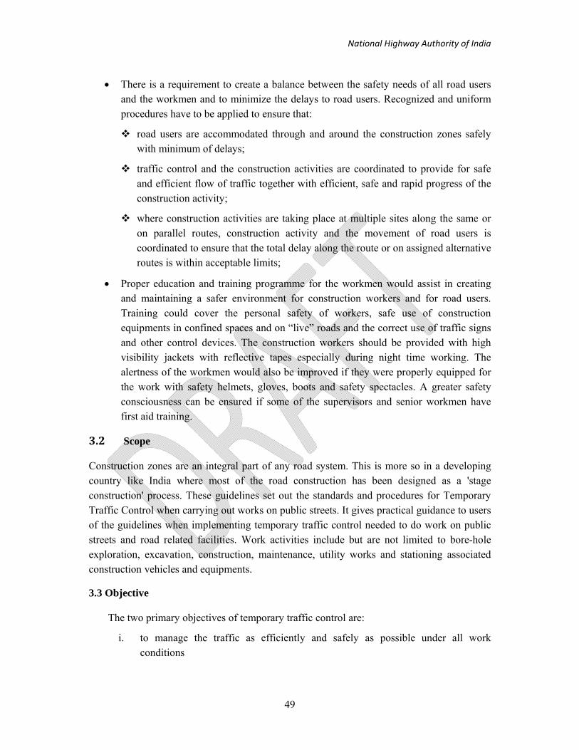
National Highway Authority of India
49
• There is a requirement to create a balance between the safety needs of all road users and the workmen and to minimize the delays to road users. Recognized and uniform procedures have to be applied to ensure that:
road users are accommodated through and around the construction zones safely with minimum of delays;
traffic control and the construction activities are coordinated to provide for safe and efficient flow of traffic together with efficient, safe and rapid progress of the construction activity;
where construction activities are taking place at multiple sites along the same or on parallel routes, construction activity and the movement of road users is coordinated to ensure that the total delay along the route or on assigned alternative routes is within acceptable limits;
• Proper education and training programme for the workmen would assist in creating and maintaining a safer environment for construction workers and for road users. Training could cover the personal safety of workers, safe use of construction equipments in confined spaces and on “live” roads and the correct use of traffic signs and other control devices. The construction workers should be provided with high visibility jackets with reflective tapes especially during night time working. The alertness of the workmen would also be improved if they were properly equipped for the work with safety helmets, gloves, boots and safety spectacles. A greater safety consciousness can be ensured if some of the supervisors and senior workmen have first aid training.
3.2 Scope
Construction zones are an integral part of any road system. This is more so in a developing country like India where most of the road construction has been designed as a 'stage construction' process. These guidelines set out the standards and procedures for Temporary Traffic Control when carrying out works on public streets. It gives practical guidance to users of the guidelines when implementing temporary traffic control needed to do work on public streets and road related facilities. Work activities include but are not limited to bore-hole exploration, excavation, construction, maintenance, utility works and stationing associated construction vehicles and equipments.
3.3 Objective
The two primary objectives of temporary traffic control are:
i. to manage the traffic as efficiently and safely as possible under all work conditions

National Highway Authority of India
50
ii. to lay down procedures to be adopted by field engineers to ensure the safe and efficient movement of traffic and also to ensure the safety of workers at site undertaking the construction.
Traffic control aims to give adequate warning and clear information to motorists about the nature of works on site. This will translate into correct actions required in order to pass the work site safely. Traffic control shall also include measures to safeguard pedestrians when necessary. Proper traffic control also protects those who are directly involved in carrying out the works. It is necessary that the existing work procedure and contract conditions are standardized to provide for the proper management of the construction site so that all road users (that is pedestrians, cyclists, motor cyclists, animal traffic and vehicular traffic) are properly and safely accommodated.
3.4 Process
The process of ensuring safe work zone conditions is divided into three stages (i) Before start of work (ii) During execution and (iii) Partially completed section. The details of this process are shown in Figure 3-1.
1. Before Start of Work: Contractor2 is responsible for preparing a site specific Traffic Management Plan (TMP) as specified in these guidelines. The plan must be approved by the Engineer. In case of non compliances, the plan must be revised and resubmitted for approval. After Engineer’s approval on the plan, it has to be implemented on the ground and again approved by the Engineer. Work cannot start without getting the necessary approval from the Engineer; Road Construction Agency representative must check the document compliance and field compliance on a sample basis.
2. During Execution: The traffic management arrangements must be checked on ground as per the checklists provided in these guidelines by Engineer. Warning must be issued if compliance is below 80% and work must stop if compliance is found to be below 70%, or repeated noncompliance.
3. Partially Completed Section: Often due to staged construction method, partially completed sections are opened for traffic operations. TMPs must be prepared before opening the section for traffic to indicate temporary markings and temporary signages.
2 (i) Public Works Department/National Highway Authority of India/Municipal Corporation – If the work is being carried out by the department itself. (ii) Contractor – If the work has been awarded to a contractor by the road owning agency.
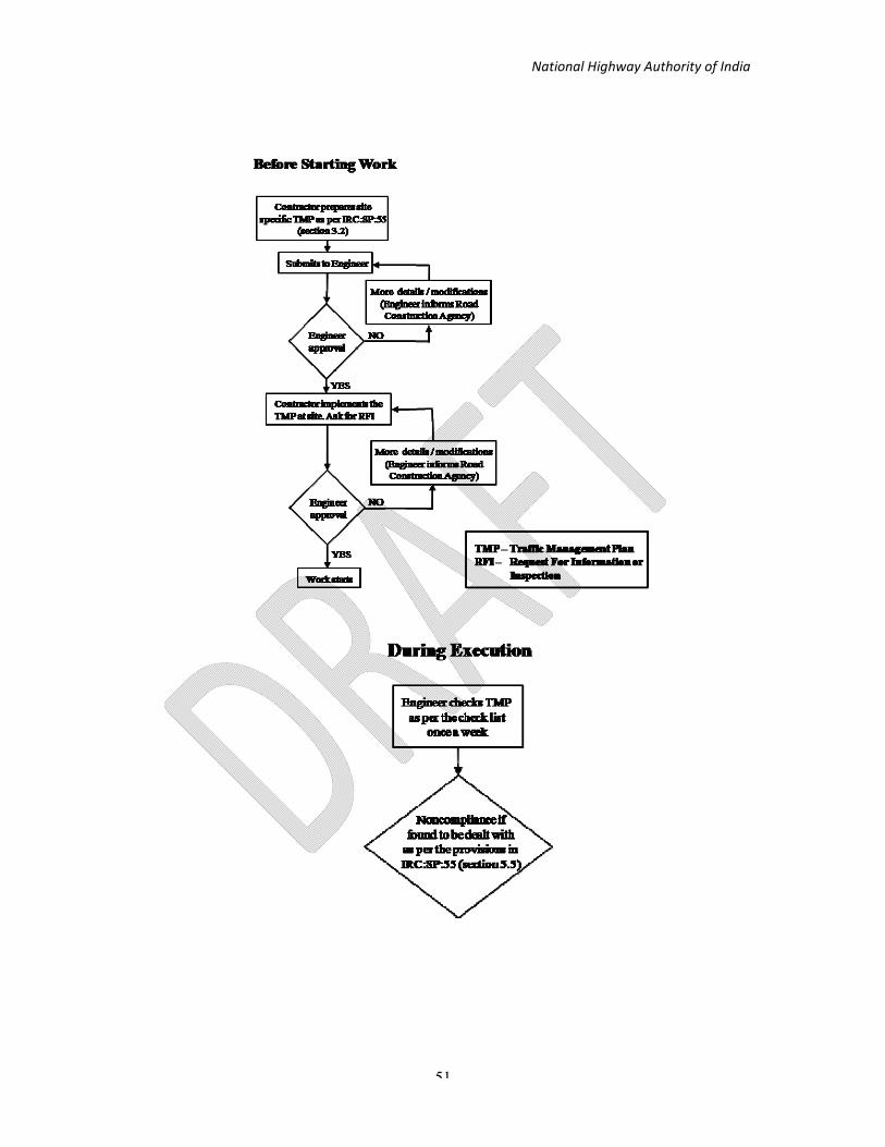
National Highway Authority of India
51

National Highway Authority of India
52
Figure 3-1: Traffic Management Process for Construction Zones

National Highway Authority of India
53
3.5 Definitions
For the purposes of these guidelines, the following definitions apply unless the context otherwise requires:
(1) “advance warning zone” means the area to warn the road user of the approaching
hazard and to prepare them for the change in driving conditions. (2) “transition zone” is the area in which the traffic is guided into the altered traffic flow
pattern around the working zone.
(3) “working zone” means the entire section of the road over which temporary traffic control related to the work activity is exercised.
(4) “carriageway” means that part of the road exclusive of any shoulders constructed for
use by vehicular traffic.
(5) “traffic control” means the process required to regulate, warn and guide road users and advise them to traverse a section of a road in the proper manner.
(6) “traffic control devices” means the signs, cones, barriers, flashing lamps or other devices placed temporarily on or adjacent to a road to regulate, warn, or guide road users.
(7) “detour” means traffic is directed to another road to bypass the closed area.
(8) “diversion” means traffic is diverted to a temporary road or lane placed in or next to the carriageway.
3.6 Guiding Principles
The guiding principles for safety in road construction zones are to:
(i) Warn the road user clearly and sufficiently in advance;
(ii) Provide safe and clearly marking lanes for guiding road users; (iii) Provide safe and clearly marked buffer and work zones;
(iv) Provide adequate measures that control driver behaviour through construction zones.
Roads with construction sites have higher accident rate, when compared with similar sections of road without construction sites.

National Highway Authority of India
54
3.7 Phases of Traffic Control
There are five phases of traffic control for major projects:
1. Planning Phase: - To identify and include traffic control requirements in the contract specification, work program and method of construction.
2. Design Phase: - To design the Traffic Control Plan in detail, with regard to types, location and layout of traffic control devices for submission to the road authority for approval.
3. Implementation Phase: - To install the temporary traffic control devices safely in accordance with the approved Traffic Control Plan.
4. Operation and Maintenance Phase: - To inspect the Traffic Control Plan and devices regularly by day and night to ensure that they are effective and absolutely safe.
5. Close out Phase: - To remove all the traffic control devices safely and reinstate the permanent traffic scheme
3.8 Components of Construction Zone
The policy is to keep the closure of the roads to a minimum and to ensure that traffic is delayed as little as possible by the construction operations. Highest regard is to be given to traffic safety as well as to provide a safe working environment to the workmen. Before starting the construction work, which will influence traffic, the contractor has to get the legal permission of the road traffic authority and local police about the means and extent of securing the construction zone. The traffic management strategies to be used at construction zones should ensure that traffic safety is an integral and high priority element of the project. This can be ensured by avoiding inconvenience to traffic control elements and traffic operations must be carried out so that care and attention to roadside safety is never slack during the progress of project.

National Highway Authority of India
55
3.9 Traffic Control Zone
For the purpose of these guidelines, the construction zone describes that area of the road which is affected by the works and which affects traffic flow and road users. The main area of interest can be called in this context as the "Traffic Control Zone". It includes all those areas of carriageway in advance of the actual work site which are required for advance warning of the hazard as well as safety zones, the transition zones and the working zone itself. These elements are shown in Figure 3-2 and defined in succeeding Paragraph.
1. In rural areas, the problems at many construction zones is accentuated by the availability of only an undivided carriageway, which may involve problems of either the temporary acquisition of land for diversions, or the sharing of the limited remaining road space by road users under some form of traffic control. In any case it should be ensured that road user is properly segregated from the working zones.
2. In urban areas where construction zones are likely to be even more constrained, diversions may have to be taken over adjacent sections of the road network in addition to the sharing of road space to road users (for example, shuttle working under signal control). The effects of construction zones may therefore be felt over a wide area.
3. The Traffic Control Zone can be divided into four components, that is, the Advance Warning Zone, the Transition Zone, the Working Zone and the Termination Zone. All construction zones will have a working zone, which is flanked, by a transition zone for each direction of approaching traffic and an advanced warning zone will precede these in turn.

National Highway Authority of India
56
Note: 1) The sign boards need to face the oncoming traffic
2) See Table 3-2 for Taper Length
3) Traffic cones are interchangeable with Drums/Traffic Cylinders
Figure 3-2: Elements of Traffic Control Zone

National Highway Authority of India
57
3.10 Advance Warning Zone
a. The “Advance Warning Zone” is the area to warn the road user of the approaching hazard and to prepare them for the change in driving conditions. It is essential for traffic control in the construction zone. It should provide information on:
(i) The presence of the hazard through the "Road Works Ahead" sign, accompanied by the distance to the hazard;
(ii) Any change affecting traffic arrangements (such as a reduction in the number of lanes and/or in the speed limit) within the traffic control zone;
(iii) Extent of the hazard (for example; the length of restriction); and for general information;
(iv) The type of hazard.
b. The advance warning zone is where the reduction in speed of vehicles should be notified. The drivers should be advised to reduce their speed so as to achieve the desired transition zone. The information in this zone is conveyed through a series of traffic signs along the length of the zone. Actual signs to be used are discussed in later paragraphs.
3.11 Transition Zone
a) The transition zone is the area in which the traffic is guided into the altered traffic flow pattern around the working zone. This is one of the most crucial zones as far as safety aspects are concerned because most of the movements involved are merging/turning movements.
b) At other construction zones, it may be necessary to divert traffic away from the original carriageway and the design of the temporary road geometry through the transition zone should take into account the following factors:
i. the turning radius of the longest vehicle that generally uses the road should be the ruling radius for curves;

National Highway Authority of India
58
ii. where changes in vertical profiles are required, these should be shallow enough to allow safe passage of animal drawn vehicles (if these are present in significant numbers);
iii. the zone should have good drainage to avoid any ponds on the road surface;
iv. sources of dust should be minimized. This is not only essential for good visibility but also for clearer maintenance of signs and barricades in the zone.
c) The traffic is taken across the transition zone mostly with the help of signs, barricades, channelizing devices and pavement marking. The various types of barricades and channelizing devices are discussed in detail in later paragraphs. The guiding principle for their design is that they should convey the message clearly and unambiguously. The colour and shape of the signs should also be as the standards noted in later paragraphs to eliminate the confusion caused by use of different signs for the same purpose.
d) All the signs/barricades and road safety devices are to be maintained properly and kept clean of dust at all times. Sufficient stock of these should be maintained at the site so as to replace the damaged or vandalized signs/barricades. Proper lighting arrangements for illuminating these signs must be made during the night hours. Most of the accidents at nights involve collision between vehicles and objects rather than vehicle to vehicle collision. Reflective paints/sheets must therefore be used for the signs/barricades and road safety devices so that these are visible at all times.
e) Very often, the road width available through the transition and working zones is quite insufficient for simultaneous passage of both the up and down traffic. In both the cases, a waiting area with a properly demarcated stop line has to be provided for the vehicles.
3.12.Working Zone
a) The working zone is where the actual construction is being undertaken.
b) Speeds should continue to be controlled in this zone because of the close proximity of moving construction plant and workmen.

National Highway Authority of India
59
c) The path of the traffic must be very clearly delineated through the traffic control zone to avoid vehicle intruding into the work area. Delineation and channelizing devices discussed below must be used effectively for this purpose. Where the work site uses machinery with revolving booms like cranes or excavators the intrusion of moving parts must be taken into account when determining the lateral clearances for the buffer or safety zone.
3.12.1 Components of Working Zone
The working zone comprises the following components (Figure 3-3).
(1) Work Area – Area occupied physically by the works. (2) Work Space — Space set aside around the works area for workers, equipment and material. Method of construction will determine the space needed for the work. (3) Traffic Space — Area where traffic is routed through the activity area. Traffic space must be properly delineated and channelled to guide traffic through safely. Road capacity and traffic demand will determine the width of the traffic space.
(4) Safety Buffer — Space separating traffic space from workspace. No storage of equipment and material, parking of vehicles, or presence of worker (except maintenance activity) is allowed for the safety of the workers and road users. It allows an errant vehicle to stop in time before hitting the workspace. The two types of safety buffers are the longitudinal safety buffer and the lateral safety buffer. (a) Longitudinal safety buffer is a space upstream of a workspace. (b) Lateral safety buffer is to separate workspace from traffic space.

National Highway Authority of India
60
Figure 3-3: Components of Working Zone

National Highway Authority of India
61
3.13. Termination Zone
a) The termination zone provides a short distance to clear the work area and to return to normal traffic lanes. It extends from the downstream end of the work area to the sign indicating the end of work zone.
b) A downstream or closing taper may be placed in the termination zone. It may be useful in smoothening the flow of traffic. However, it may not be advisable when the trucks carrying material move into the work area by reversing from the downstream end of working zone.
c) There may be occasions when termination zone could include a transition. For example, if a taper is used to shift traffic into opposing lanes around the work area, then the termination zone should have a taper to shift back to its normal path. This taper would then be in the termination zone for the opposing direction of traffic.
d) If the construction zone is situated on a divided-carriageway, there will need to be a smaller length transition zone to return the traffic to the original lanes.
3.14. Tapers
Tapers may be used in both the transition and termination areas. Whenever tapers are to be used in close proximity to an interchange ramp, crossroads, curves, or other influencing factors, the length of the tapers may be adjusted.
Support: Tapers are created by using a series of channelizing devices and/or pavement markings to move traffic out of or into the normal path.
Length: The recommended ratios for taper length are shown in the Table 3-1

National Highway Authority of India
62
The definitions of the tapers (Figure 3-4) are: —
(1) A Merging Taper — used where two lanes merge into one lane. It needs a longer distance for the drivers to adjust their speed to merge with an adjacent lane before the end of transition.
(2) A Shifting Taper — used when a lateral shift is needed without merging. (3) A Shoulder Taper — used on an expressway when work is in progress on a
shoulder lane.
Figure 3-4: Types of Tapers and Buffer Spaces

National Highway Authority of India
63
Table 3-1 Recommended Ratio for Taper Length (N)
Speed (km/h) 40 50 65 80
Merging 1:5 1:10 1:25 1:40 Shifting 1:3 1:5 1:13 1:20 Shoulder NA NA NA 1:5
Note: If the ratio shows 1:40, N = 40
Examples of the taper length calculation are shown in APPENDIX -I and the summary is given in Table 3-2.
Table 3-2 Summary of Taper Length calculated
Design Speed Taper Length Merging Taper Shifting Taper
Km/h (m) (m) 80 140 70 65 90 50 50 40 20 40 20 10 30 20 10
The following factors shall be considered when designing a taper. They are: —
(1) Tapering of more than 1 lane should be done one lane at a time. The distance of the tapers is twice the normal taper length.
(2) A longer taper is not necessarily better than a shorter taper (particularly in urban areas) because an extended taper tends to encourage sluggish driving and delay lane changes.
(3) The start of the taper should be located such that its full length is visible at 60m to 100m ahead. The start of the taper should be located at the upstream of a bend so that it is clearly visible on the approach.
(4) Transition area is also a safety zone. Nothing other than traffic control devices are allowed in the transition zone.
(5) Devices should be spaced such that the taper would appear uniform and continuous to approaching motorists, and traffic cannot weave around them easily.

National Highway Authority of India
64
3.14.1 Designing of Taper Length for SHORT-DURATION Work
Typical taper for SHORT-DURATION work (i.e. 12-24 hours) shall be a straight line as shown in Figure 3-5. Portable temporary traffic control devices shall be used to delineate the taper as follows: —
(1) Traffic Cones spaced at 6m and 3m c/c for expressway and other roads respectively.
(2) Plastic barricades with the retro-reflective board facing the traffic, spaced at 6m and 3 m c/c for expressway and other roads respectively.
(3) Continuous water-filled barriers with retro-reflective disc.
Figure 3-5: Taper for Short duration work
3.14.2 Designing of Taper Length for SHORT DURATION and LONG DURATION Work
The taper for SHORT DURATION and LONG DURATION work (i.e. 24 hours-7 days) shall be as shown in Figure 3-6. The downstream of the taper is a smooth curve for smoother and better traffic flow.

National Highway Authority of India
65
Figure 3-6: Taper for Short and Long duration work
The typical setting up of the taper curve is as shown in Figure 3-7 The taper is a straight line from Ch 0 m to Ch 0.6L m and a square parabolic curve from Ch 0.6L m to Ch L m. A working example is given in APPENDIX -I to assist the designer to design the taper for short duration and long duration work.
Figure 3-7: Taper curve for short and long duration work

National Highway Authority of India
66
The calculation of En for short and long duration work is shown in APPENDIX -I.
3.14.3 Designing of Taper Length for LONG DURATION Work
The taper for extended LONG DURATION (i.e. beyond 7 days) and complicated traffic diversion shall be a S-curve as shown in Figure 3-8 for a smooth flow of traffic. A square parabolic S-curve shall be used to set out a taper length for changes to cross-section due to changes in lane width, median width, carriageway width, number of lanes, auxiliary lane, slip road etc. This is the inner edge of the 200mm wide thermoplastic pavement edge marking. The typical setting up of the taper S-curve is as shown in Figure 3-9.
A working example is given in APPENDIX -I to assist the designer to design the taper.
Figure 3-8: Taper for extended Long Duration work and Complicated Traffic
diversion

National Highway Authority of India
67
Figure 3-9: Taper Curve for extended Long Duration work and Complicated
Traffic Diversion
The calculation of En for extended Long Duration work and Complicated Traffic diversion is shown in APPENDIX -I.
3.15 Other Aspects
The distance between two traffic control zones should be such that the flow of traffic can return to normal stream between them.
The length of traffic control zone will vary and depend on the work being undertaken. The lengths of the advanced warning and transition zones are governed by the speed of approaching vehicles and the locations of the site. The recommended lengths for each component of the zones for a well located site (with a clearly visible approach) are given in Table 3-3.
It may be necessary to extend the advance warning zone where approach visibility is poor and this will vary on a site by site basis but should not be less than that specified. On occasions additional signing to that discussed later may need to be provided to give not only sufficient warning but additional reminders through the advance warning zone. The longitudinal and lateral buffer zone clearances are shown in Table 3-11.

National Highway Authority of India
68
Table 3-3: Recommended Lengths of Traffic Control Zones
Average Approach
Speed (km/h)
Length of Advance Warning
Zone, D (m)
Length of Transition Zone
(m)
Length of Working Zone
(m)
50 or less
150
50
Varies
51-80
150-300
50-100
Varies
81-100
300-500
100-200
Varies
Over 100
1000
200-300
Varies
There may be different situations in construction zone requiring full or partial, closure of roads for example
(a) Closure of berms only e.g. repairs to slopes, construction / maintenance of road side drains, gravelling/paving of hard shoulders, maintenance of traffic signs, repairs to parapets of cross drainage works, guard rails;
(b) Closure of small areas of the carriageway only, e.g. repairs to potholes, resurfacing, renewing road markings;
(c) Closure of lane of the carriageway along with the closure of berms e.g. widening of the carriageway, repairs to culverts, flood damage repairs. These types of works can further be classified according to availability or non-availability of space for operating the displaced traffic on the remaining portion of the carriageway and shoulders.
(d) Closure of the entire road width for undertaking repairs to pavement or culvert.
Gaps in the work area may be avoided as these may falsely give an impression to the road users that they have passed the work area. The guide signs in this regard should be installed at appropriate locations.

National Highway Authority of India
69
3.16 Highway passing through villages and small towns
i. The same basic rules and layouts will apply in urban areas but may be it would be necessary to modify the layouts according to site requirements. At all times the safety of all road users as well as the workmen should be taken into account.
ii. In urban situations, where road works are to be carried out, more attention should be given to the problems of pedestrians and non-motorized vehicles in heavy traffic volumes. As far as possible, the road works should be carried out at night, whenever night time road repairs are not possible, then only day time repairs should be carried out. Repairs during peak hours should also be avoided.
iii. Road users should be channelized and routed through and around area under repair with minimum of delays. Driver behavior should be effectively influenced so that the speeds are reduced to desired levels on approaches to construction zones. Traffic calming devices like rumble strips and speed humps should be used wherever necessary. The traffic control and construction activity should be coordinated in such a manner as to provide for safe and efficient flow of traffic together with safe, efficient and rapid progress of construction activity.
iv. As pedestrians are likely to be present at urban sites, there must always be safety or buffer zone between the outer pedestrian barrier and the traffic.
v. Availability of proper sight distance for the movement of vehicles at the recommended speed for the stretch in the work zone should always be kept in the mind.
3.17 Traffic Control Devices
General
Traffic control devices are the equipments and installations over and on the road, which individually and collectively perform the following tasks;
a) warn the road user;
b) inform the road user;
c) guide the road user;
d) modify road user behavior;
National Highway Authority of India
70
e) protect the road user and the vehicle;
f) ensure safe passage to the road user; and
g) provide a safe working area.
A traffic control device in order to be effective should,
(i) Fulfill the intended need;
(ii) Command attention and respect of road users;
(iii) Convey the message in a simple and clear manner;
(iv) Allow adequate time for proper response from road users; and
(v) Have adequate conspicuity both in day and night.
The primary traffic control devices used in work zones are signs, delineators, barricades, cones, pylons, pavements markings and flashing lights. The following general rules should apply to all traffic control devices with the traffic control zone.
(i) Comprehension: All traffic control devices should be capable of being easily understood. A particular device must convey one and only one meaning. Good and clean condition of the device aids comprehension;
(ii) Visibility and Stability : Devices should be within the cone of vision of the driver and be placed such that it allows adequate response time at the average speed or the desired speed through the traffic control zone. All traffic control devices should be clearly visible by day and night, at these speeds and under the usually prevailing climatic conditions. They should be kept properly aligned and legible at all times. Foliage or any other obstruction should not be allowed to impede the view of these devices, nor should wind, road dirt or the like be allowed to obscure their face. The traffic control devices must be able to resist the local wind pressure, rain and the vibrations etc, of the passing traffic but these should not act as rigid obstacles in the event of a collision.
3.17.1 Signs
The road construction and maintenance signs fall into the same three major categories as do other traffic signs, Mandatory/Regulatory Signs, Cautionary/Warning Signs and Informatory/Guide Signs. The main signs that would be utilized are shown in

National Highway Authority of India
71
Figure 3-10, Figure 3-11 and Figure 3-12. These guidelines also cover signs that are not included in IRC: 67 but are considered desirable to aid drivers' comprehension of the route through the road works. Each sign should be well located so that its message is seen and is clear, which will be assisted if the surroundings are devoid of “unnecessary” signs and other clutter. These signs should be of Class B Sheeting as per IRC:67-2011.
3.17.1.1 Sign Placement
The correct positioning and size of signs will ensure that it can be observed and recognized, thereby providing the driver with more time to react and take action.
The following principles should govern the positioning of signs:
a) Their location should have clear visibility;
b) They should be so placed that driver would have adequate time for responses.
c) As a general rule, signs should be placed on the left-hand side of the road. Where special emphasis is required, duplicate signs should be installed on the left and right side of roadway. In case of hill roads, the sign shall generally be fixed on the valley side of the road unless traffic and road conditions warrant these to be placed on the hill side ;
d) Roll up signs mounted on portable supports may be placed within the roadway itself.
e) Roll up signs may also be mounted on or above the barricades
f) The signs should be covered or removed when they are not required.
Signs should normally be mounted:
(1) Approximately at right angle to the line of sight facing the traffic. (2) Slightly skewed from the traffic if mirror reflection occurs such that it reduces
legibility of the sign. (3) Do not obstruct existing traffic signs. (4) Typical clearances (minimum) for post-mounted signs are as follows:
Vertical - 2.5m above ground level Lateral - 0.6m from edge of traffic lane
On kerbed roads, the extreme edge of the sign adjacent to the road shall not be less than 600 mm away from the edge of the kerb. On un-kerbed roads, the extreme edge of the sign adjacent to the road shall be at a distance of two to three meter away

National Highway Authority of India
72
from the edge of the carriageway depending on local conditions but in no case, shall any part of sign come in the way of vehicular traffic. Where signs are in position for some time and pedestrians are expected, the lower edge of the lowest sign should not be less than two meter above the surface on which it stands. Where pedestrians are not expected, signs may be mounted on trestles (tripod) but during wet conditions should be mounted away from the traffic “splash” zone so that they do not become obscured by dirt. Trestle mounted signs are particularly for short term temporary works. These should be so placed that pedestrians’ movements are not obstructed. In urban conditions, it may not be possible to erect new sign poles in footways crowded with public utilities and "A" frames may be the only alternative. Signs for longer term works should follow normal rules for the mounting of permanent signs.
The legend on all signboards shall be Hindi/English/Regional language and should follow the format given in Table 3-4.
Table 3-4: Format of Legends on Shoulder Mounted Signs*
S.No. Language Font type
1. Hindi Hindi7
2. English Transport Medium
3. Regional Language As per Local Practice
(*Source: IRC-67:2011)
3.17.1.2 Mandatory/Regulatory Signs
Mandatory/Regulatory Signs impose legal restriction on all traffic. It is essential, therefore, that they are used only after consulting the local police and traffic authorities. The most likely type of regulatory signs to be used in traffic control zones are Stop, Give Way, One Way, Straight Prohibited/No Entry, Left/Right Turn Prohibited, U-Turn Prohibited, Overtaking Prohibited, No Parking, No Stopping and No Standing, Compulsory Keep Left/Right, Compulsory Turn Left/Right, Compulsory Ahead, Compulsory Ahead or Left/Right Turn, Axle Load Limit, Height Limit, Length Limit, Width Limit, Restriction Ends, Maximum Speed Limit (Figure 3-10, Figure 3-11, Figure 3-12)
i Various other signs that are needed to regulate traffic may be required which have not been standardized. They should conform to the general requirements of shape and colour, and their message should be brief, legible and clearly understandable.
i. The minimum size of Regulatory signs must be as follows:

National Highway Authority of India
73
a. Give Way Sign – 900mm Equilateral triangle
b. Signs which are Circular in shape – 900mm diameter
ii. The colour of Regulatory signs should be White Base Red Border and Black Letter/Symbol/Legend etc. However, for Stop sign and No Entry sign, the scheme shall be Red Base and White Letter/Symbol. The border of Stop sign shall be of White colour.
Other regulatory signs as per Figure 3-12 shall be of colour scheme as under
a. For Figure (i), (ii), (iii) - Fluorescent Orange base and Black letter.
b. For Figure (iv) – White base and Letter/Symbol/Border of Red colour.

National Highway Authority of India
74
Figure 3-10: Regulatory Signs
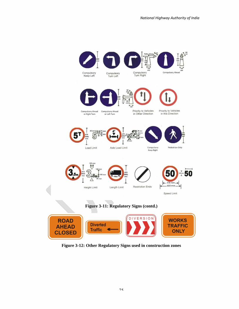
National Highway Authority of India
75
Figure 3-11: Regulatory Signs (contd.)
Figure 3-12: Other Regulatory Signs used in construction zones

National Highway Authority of India
76
3.17.1.3 Cautionary/Warning Signs
Cautionary/Warning Signs in the traffic control zone are utilized to warn the drivers of specific hazards that may be encountered. Drivers should be altered to potential hazards in sufficient time to adjust their movement and speed. The most common type of cautionary/warning signs for use in the traffic control zone are: Men at Work, Road Widens, Right lane Diverted, Right Lane Closed, Left lane closed, Median Closed, Diversion to Other Carriageway, Traffic Signal Ahead, Two Way Operation, Rough Road, Loose chipping, Divided Road and divided Road Ends (Figure 3-14)
i. In case of divided carriageways, the signs should be provided both adjacent to the shoulder and on central median so as to be visible from all lanes. Refer Table 3-5.
ii. The minimum size of Warning Signs must be 1200mm×1200mm of Rhombus shape.
iii. All Warning Signs shall have Orange Base of Class B sheeting as per IRC-67:2011 & the letters/symbol/legend shall be of black colour.
Table 3-5 Minimum Sightline Distances and the Minimum Size of the Signs
Average Speed (km/h)
Distance of first sign in advance of
the first channelizing device
(m)
Size of Warning Sign
(mm)
Minimum number of
signs in advance of the
hazard
Distance E to “End of
Work Zone” Sign
(m) Under 50
100
1200
3
10-30
51-60
100-300
1200
3
10-30
61-80
120-300
1200
3 or 4
10-30
81-100
300-500
1200
4
30-45
Over 100
1000
1200 to 1500
4
30-45

National Highway Authority of India
77
Figure 3-13: Warning Sign Details

National Highway Authority of India
78
Table 3-6 Acceptable Limits for Size of Letters and Visibility Distance*
(*Source: IRC-67:2011)

National Highway Authority of India
79
Note: Signs should be detailed as per speed limits and specifications as per Figure 3-13
Figure 3-14: Warning signs

National Highway Authority of India
80
On Un-kerbed Roads
Figure 3-15: Traffic Warning Sign
3.17.1.4 Informatory/Guide Signs
Informatory/Guide signs are required at traffic control zones to provide the necessary information and guidance for the alternative route and work being done. These signs shall have white arrows/border/letters on blue/green background. Fluorescent Orange sheeting shall conform to Class B sheeting as per IRC-67:2011. The commonly used guide signs are public telephone, hospitals, etc.
3.17.2 Delineation and Channelizing Devices
Delineation and channelizing devices shall be used in conjunction with other devices to: (1) Separate traffic from the workspace, pavement drop-offs, pedestrian paths, or opposing traffic. (2) Guide road users safely by indicating clearly the edge of the route and the path they should take. (3) Guide and direct the approaching vehicles smoothly and gradually into the designated lane/s to pass the work zone safely.
The two forms of devices serve slightly different functions.

National Highway Authority of India
81
(1) Channelizing: Refers more to the formation of the navigational paths. Devices are
used to direct vehicles into pre-determined paths in a safe and orderly manner.
(2) Delineation: Refers more to the marking of boundaries. Delineation devices are
installed to indicate clearly the alignment of the road and width of the path in which the
vehicles should manoeuvre.
The channelizing devices such as cones, traffic cylinders, drums and water-filled barricades are placed in or adjacent to the roadway to control the flow of traffic. These should normally be retro-reflective (Class B sheeting as per IRC-67:2011).
3.17.2.1 Traffic Cones
a) Traffic cones are 500mm, 750 mm and 1000mm high and in square shape at base and are often made of plastic or rubber and normally have retro-reflective white bands (Class B sheeting as per IRC-67:2011). (Refer Table 3-7)
Table 3-7 Height of Cones, Cylinders and Drums according to Class of Sheeting
Size & No. of Reflective
Sleeve
Class of Sheeting
Height of Cones/Cylinders/Drums
(mm)
Two Sleeves of 100mm each Class B as per IRC-67:2011 500
Two Sleeves of 150mm each Class B as per IRC-67:2011 750
One Sleeve of 300mm Class B as per IRC-67:2011 1000

National Highway Authority of India
82
a) Their advantages are that they:
i. cause minor impediments to traffic flow and capacity
ii. are well recognized and understood, without damaging vehicle when hit
iii. can be easily stored and transported
iv. can be fastened to the pavement and self-restoring when hit.
b) Their disadvantages are that they have minimal respect of drivers, can be equally penetrated, displaced and knocked over and require special treatment for night times.
c) Cones are easily blown over or displaced unless their bases are loaded with ballast or anchored. It may, therefore be sometimes necessary to double the cones in order to provide added weight, use the cones with special weighted bases, use heavier weighted cones or use weights such as sand bag rings to provide increased stability but this weight should not present a hazard. The cones should be placed close enough together to give an impression of continuity. The spacing of cones should be 3 m (close) or 9 m (normal) or 18 m (wide). Where cones have to be used at between 45º and 90º to the line of traffic, their spacing should be 1.2 m. Large size cones should be used where speeds are relatively high or wherever more conspicuous guidance is needed.
d) They may be used in long duration works in conjunction with temporary pavement marking. They shall be placed at least 300 mm away from the edge of the traffic lane (Figure 3-16).

National Highway Authority of India
83
Figure 3-16: Placement of Traffic Cone
3.17.2.1.1 Cone Design
Cones shall be fluorescent orange and shall be made of a material that can be struck without damaging vehicles on impact. Cones shall be a minimum of 700 mm in height when they are used on freeways and other high- speed highways, on all highways during night time, or whenever more conspicuous guidance is needed. For night time use, cones shall be retroreflective or equipped with lighting devices for maximum visibility. Retroreflection shall be provided by a white band 150 mm wide, no more than 100 mm from the top of the cone, and an additional 100 mm white band a minimum of 50 mm below the 150 mm top band. The reflective sheeting used for bands shall be of Class B sheeting as per IRC-67:2011.
3.17.2.1.2 Retroreflectivity specs for the sleeve
Sleeve shall display essentially the same colour both in daylight and under automobile headlights at night, when viewed at distances of 50 feet or greater with typical construction work zone placement of devices. The coefficients of retro-reflection shall be in accordance with ASTM E 810. E 810 values of 0° and 90° rotation averaged to determine conformance to the RA limits, for the minimum requirements of Class B sheeting of IRC-67:2011.

National Highway Authority of India
84
3.17.2.1.3 Flexibility specs
The sleeve material shall have Class B sheeting as per IRC-67:2011 retroreflectivity requirements and shall show no cracking when conditioned for 24 hours at 0° C and wrapped and bent around a 1/8 inch mandrel in one second’s time with the liners removed.
3.17.2.1.4 Cone Application
Traffic cones are used to channelize traffic, divide opposing traffic lanes, divide traffic lanes when two or more lanes are kept open in the same direction, and delineate short-duration maintenance and utility work. Steps should be taken to ensure that cones will not be blown over or displaced by wind or moving traffic. Cones shall have a heavy rubber base to provide stability during heavy wind loads and should not present a hazard if the cones are inadvertently struck.
3.17.2.2 Traffic Cylinders/Spring Posts
a) Traffic Cylinders/Spring Posts are similar to traffic cones, however they are less effective and shall be used only when space restriction does not permit the use of larger devices.
b) They shall be easily fixed on the road or paved surface and not be easily displaced.
c) The colour shall be fluorescent orange that offers good day visibility.
d) High Intensity Grade retro-reflective bands shall be fitted for night visibility.
e) It shall be at least 750 mm tall when fixed onto the ground, and at least 80 mm wide.
f) They may be used in long duration works in conjunction with temporary pavement marking. They shall be placed at least 300 mm away from the edge of the traffic lane. (Figure 3-17)

National Highway Authority of India
85
Figure 3-17: Placement of Spring Post
3.17.2.3 Drums
1) Drums about 800 mm to 1000 mm high and 600 mm in diameter can be used as either channelizing on warning devices. These are highly visible, give the appearance of being formidable objects and therefore command the respect of drivers.
2) Plastic drums are lighter, pose fewer hazards to vehicles and workers and can be needed for easy transportation and shortage and generally have one or more flat sides to preclude rolling. Drums may be filled up with earth or sand for stability. Plastic drums should have White reflective strip of 100 mm. Drums should be reflectorised for use at night and should never be placed in the roadway without advance warning signs. Figure 3-18 shows some typical dimensions of cones, spring posts and drums.
3) Reflective sheeting shall be of Class B as per IRC-67:2011.

National Highway Authority of India
86
Figure 3-18: Cone, Spring Post and Drum
3.17.2.4 Water-Filled Barricades
(a) Water-filled barricades are proprietary-made modular water filled plastic containers of various sizes and shapes. (Figure 3-19)
(b) They shall be minimum 1m tall for major roads and expressway and 0.8m tall for other roads.
(c) Each unit shall come with interlocking devices for use on tangent straight and horizontal curves with mounting devices for lighting.
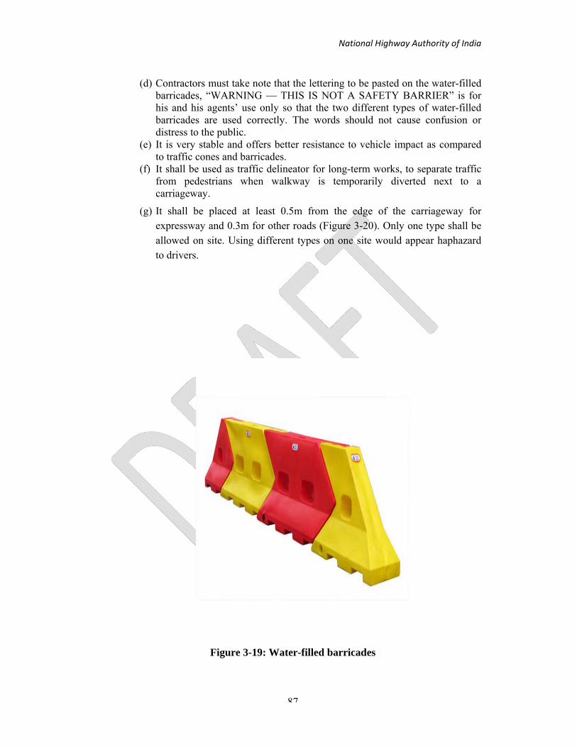
National Highway Authority of India
87
(d) Contractors must take note that the lettering to be pasted on the water-filled barricades, “WARNING — THIS IS NOT A SAFETY BARRIER” is for his and his agents’ use only so that the two different types of water-filled barricades are used correctly. The words should not cause confusion or distress to the public.
(e) It is very stable and offers better resistance to vehicle impact as compared to traffic cones and barricades.
(f) It shall be used as traffic delineator for long-term works, to separate traffic from pedestrians when walkway is temporarily diverted next to a carriageway.
(g) It shall be placed at least 0.5m from the edge of the carriageway for expressway and 0.3m for other roads (Figure 3-20). Only one type shall be allowed on site. Using different types on one site would appear haphazard to drivers.
Figure 3-19: Water-filled barricades

National Highway Authority of India
88
Figure 3-20: Placement of Water filled barricade
Table 3-8 Summary of Delineation and Channelizing Devices
Type Traffic Cone Traffic Cylinder Drum Water filled Barricade
Colour Fluorescent Orange
Fluorescent Orange
Fluorescent Orange
Fluorescent Orange
Reflective collars/bands
and Reflective Sheeting
White band with Class B sheeting
as per IRC-67:2011
White band with Class B sheeting
as per IRC-67:2011
White Reflective sheet of 100 mm
of Class B sheeting as per IRC-67:2011
Mounted with Fluorescent
Orange Retroreflective Disc of Class B sheeting as per IRC-67:2011
Min height (mm)
700 750 800 1000
Min lateral clearance
(mm)
300 300 300 300
National Highway Authority of India
89
3.17.3 Barricades
a. Barricades are intended to provide containment without significant deflection or deformation under impact and to redirect errant vehicles along the barrier. They are designed to be easily relocated and have four specific functions to:
(i) Prevent traffic from entering work areas, such as excavations or material storage sites;
(ii) Provide protection to workers;
(iii) Separate two-way traffic; and
(iv) Protect construction such as false work for culverts and other exposed objects.
b. Barricades can be portable or permanent. Portable barricades should be stable under adverse weather conditions and appear substantial but not so much as to cause excessive damage to the vehicle if they are struck. Figure 3-21 shows typical barricades; Types I and II are portable whereas Type III is permanent. The recommended dimensions of various components are given in Table 3-9.
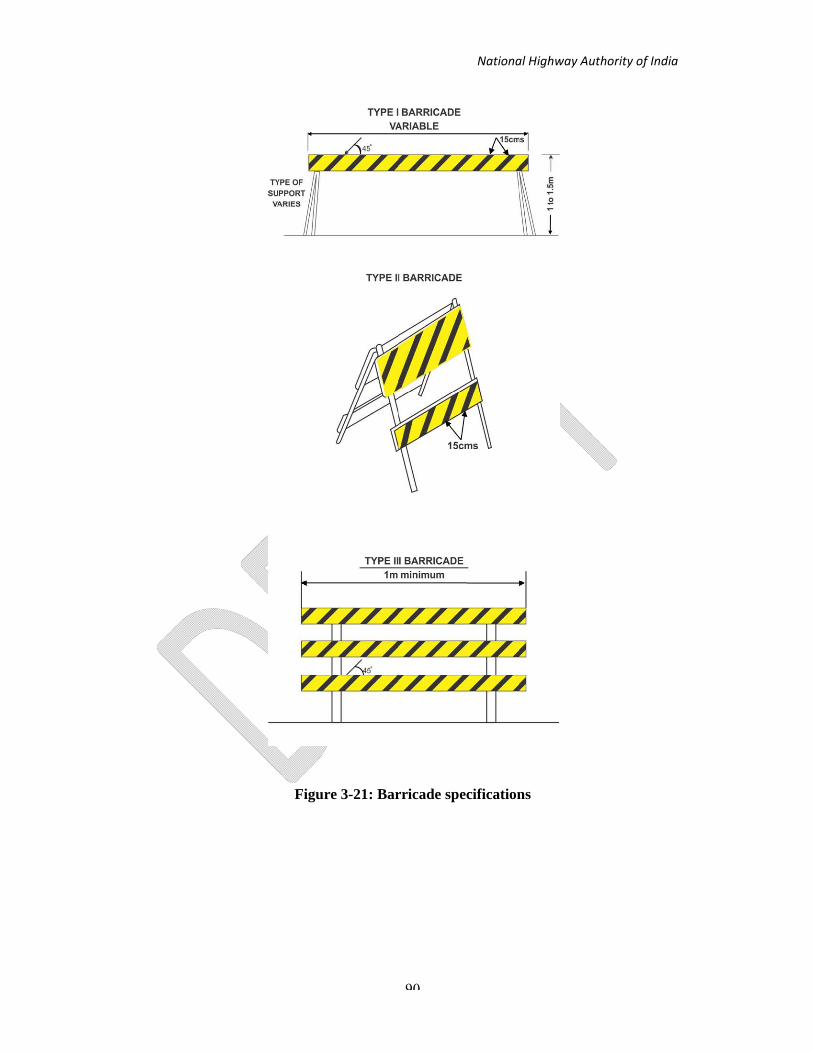
National Highway Authority of India
90
Figure 3-21: Barricade specifications

National Highway Authority of India
91
Table 3-9: Barricade Characteristics
Type / Component
I II III
Width of Rail 200 mm-300 mm 200 mm-300 mm 200 mm-300 mm
Length of Rail 2 m – 2.5 m 1 m – 1.2 m 1 m min – variable max.
Width of Strip 200 mm 200 mm 200 mm
Reflective sheeting
Class B as per IRC-67:2011
Class B as per IRC-67:2011
Class B as per IRC-67:2011
Type of Frame Heavy ‘A’ Frame Light ‘A’ Frame Fixed, Demountable
Flexibility Essentially movable
Portable Essentially Permanent
Retro-reflective sheeting
Class B sheeting as per IRC-
67:2011
Class B sheeting as per IRC-
67:2011
Class B sheeting as per IRC-67:2011
c. The horizontal members of type I and II barricades may be of wooden planks, metal or other suitable material. These should be 300 mm wide and should be painted in alternate yellow and white stripes of 150 mm width. The stripes should slope away at an angle of 45º in the direction traffic is to pass. Where the barricades extend entirely across the carriageway, the stripes should slope downward towards the direction the traffic must turn in detour. Where both left and right turns are provided for, the chevron stripes should slope downward in both directions from the centre of the barricade. The entire area of chevrons should be reflectorised so as to be visible from safe distance. Type I or Type II barricades shall be used when traffic is redirected. These barricades can be used inter-changeably and are more useful in repair work that is generally initiated on emergency basis. The support should be of an “A” frame configuration or hinged or otherwise flattened at the top to permit convenient folding and stacking for transportation. Since these barricades are susceptible to overturning in wind, their stability can be improved through ballast.
d. Type III barricades are the permanent type and can be made of wood, metal or other suitable material like masonry. These are erected at the point of closure when a road section is closed to traffic on construction projects. They may extend completely
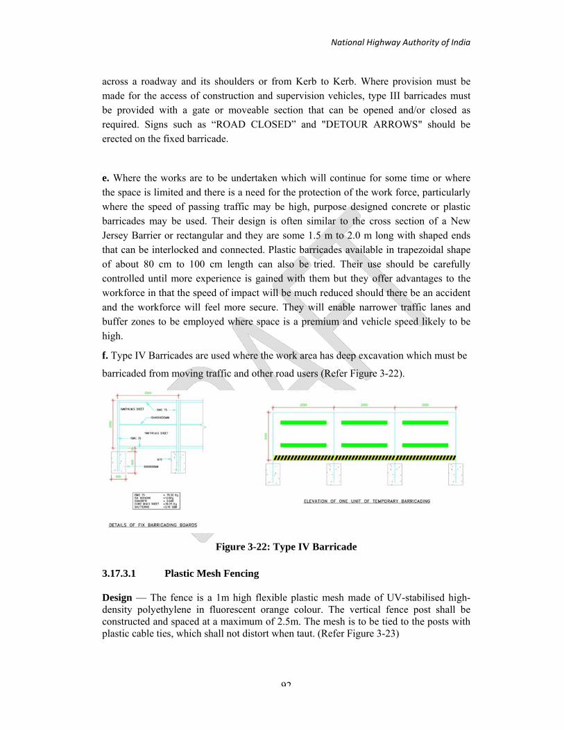
National Highway Authority of India
92
across a roadway and its shoulders or from Kerb to Kerb. Where provision must be made for the access of construction and supervision vehicles, type III barricades must be provided with a gate or moveable section that can be opened and/or closed as required. Signs such as “ROAD CLOSED” and "DETOUR ARROWS" should be erected on the fixed barricade.
e. Where the works are to be undertaken which will continue for some time or where the space is limited and there is a need for the protection of the work force, particularly where the speed of passing traffic may be high, purpose designed concrete or plastic barricades may be used. Their design is often similar to the cross section of a New Jersey Barrier or rectangular and they are some 1.5 m to 2.0 m long with shaped ends that can be interlocked and connected. Plastic barricades available in trapezoidal shape of about 80 cm to 100 cm length can also be tried. Their use should be carefully controlled until more experience is gained with them but they offer advantages to the workforce in that the speed of impact will be much reduced should there be an accident and the workforce will feel more secure. They will enable narrower traffic lanes and buffer zones to be employed where space is a premium and vehicle speed likely to be high.
f. Type IV Barricades are used where the work area has deep excavation which must be
barricaded from moving traffic and other road users (Refer Figure 3-22).
Figure 3-22: Type IV Barricade
3.17.3.1 Plastic Mesh Fencing
Design — The fence is a 1m high flexible plastic mesh made of UV-stabilised high-density polyethylene in fluorescent orange colour. The vertical fence post shall be constructed and spaced at a maximum of 2.5m. The mesh is to be tied to the posts with plastic cable ties, which shall not distort when taut. (Refer Figure 3-23)

National Highway Authority of India
93
Figure 3-23: Example of plastic mesh fence, fence post and ties
Application — It is used mainly to exclude pedestrians from a work area and for the containment of personnel. It shall be kept at least 500mm from the edge of excavation. It shall not be used near deep excavations where heavy pedestrian movement is expected or on carriageways. It shall not be used to fence up ongoing construction works area where frequent access by workers and machinery are expected. In such cases, plastic barricades shall be used instead of plastic netting.
3.17.3.2 Plastic Barricades
Design — Barricades are portable devices having two sign boards using Class B sheeting as per IRC-67:2011. The barricade shall be minimum 1m tall, be stable and not easily blown over, or displaced by moving traffic or pedestrians. (Refer Figure 3-24) It is a proprietary-made product of plastic post/frame with mounting devices for reflective disc or lamps. The material of the barricade and the ballast added to the base to provide stability shall not become a potential hazard if struck.
Figure 3-24: Example of plastic barricade posts and double
Boards Application — The portability of these devices is of particular advantage in emergencies or work that involve their regular displacement. (1) It shall be erected without gaps along pedestrian paths throughout the activity work zone for the control of pedestrian movement to prevent injury or interference with the work activity. (2) They may be erected at spacing not exceeding 20m along existing or new roads to inhibit access if road is closed to traffic use.

National Highway Authority of India
94
(3) Plastic barricades shall not be placed parallel to the traffic flow on a carriageway unless guarded by a line of traffic cones at the outer edge of the safety zone. It shall be erected at least 1.2m clear of traffic. (4) Barricades shall not be used next to deep excavations or steep falls where heavy pedestrian movement is expected. Heavy objects such as rocks or concrete chunks shall not be used as ballast. (5) They shall be placed such that a minimum distance of 0.5m separates the plastic barricade and the excavated pit. Plastic barricades shall not be used if heavy pedestrian movement is expected.
Table 3-10 Summary of Barricades
Type Plastic Mesh Fencing Plastic Barricades Colour Fluorescent Orange Alternate Fluorescent
Orange and White Board Material Polyethylene Plastic Polyethylene Plastic
Min dimension (m) 1 1 Retro-reflective Sheeting Class B sheeting as per IRC-
67:2011 Class B sheeting as per IRC-
67:2011 Post Spacing Maximum 2.5m Proprietary
Min Lateral Clearance (m) Normally not allowed on carriageway
1.2
3.17.4 Hand Paddles
a) The control of traffic through work area is an essential part of road construction and maintenance operations. Flagmen with hand signaling devices such as sign paddles play crucial role in this direction. STOP, SLOW paddle and lights and are used in controlling traffic through work area.
b) Instead of red and green flags, hand paddles of at least 450 mm diameter should be used with red and green retro reflective Class B sheeting as per IRC-67:2011. Hand paddles should be at least 600mm wide and provided with a rigid handle. The background colour of STOP should be red and its shape shall be octagonal confirming to IRC-67:2011. The word STOP should be in white, in the middle of the sign. The background colour of SLOW should be orange with white letter.
c) Since, Flagmen are responsible for human safety, it is important that qualified personnel be selected. The flagmen at the work sites are expected to stop traffic intermittently and to maintain continuous traffic past a work site at reduced speeds to help protect the workmen. For both of these functions, the flagmen must, at all time be clearly visible to approaching

National Highway Authority of India
95
traffic for a distance sufficient to permit proper response by the drivers to the flagging instruction and to permit traffic to reduce speed before entering the work site. This distance is basically related to approach speed and site conditions; however 60 m to 100 m is desirable. In urban areas, this distance shall be reduced to 20 m to 50 m. The use of sign paddle is illustrated in Figure 3-25.
d) Marshalling Torches (Figure 3-26):
(i) Hand Flashers are tough, durable working on batteries with LED bulbs. (ii) Provides warning signal for impending hazard or danger on construction
work zone, repair sites, trenches, digging of road tunnels etc. (iii)These can also be used by Traffic Police for controlling Traffic flow, for
Railways-signaling, Airport Authorities for Landing and Take-off of aircrafts, construction sites, parking areas, highway patrol.

National Highway Authority of India
96
Figure 3-25: Warning sign on hand paddles
Figure 3-26: Marshalling Torch

National Highway Authority of India
97
Figure 3-27: Temporary Installation of Signs on Maintenance Vehicle, Rollup
Stand and Barricade

National Highway Authority of India
98
3.17.5 Roll Up Signs:
Roll up signs are used in construction work zones to guide the traffic and in road ways for emergency traffic control (Figure 3-27).
Roll up signs shall be portable, changeable and shall have provisions for application on different objects depending on the need for temporary sign.
a. Mounting of the roll up sign on the portable stand
The roll up sign shall have the back support ribs to fix on the portable stand and the roll up sign stand shall have knobs to receive the short rib of the sign fascia.
The back support ribs shall be inserted in to the clamp provided on the stand and tightened using the knobs. The sign ribs shall be moved up and down to adjust the height of the sign.
b. Mounting of the roll up sign on construction or maintenance vehicles
The roll up signs shall have necessary attachments to mount it on the work zone maintenance vehicles. The back support ribs shall have dual lock high bonding tapes, mechanical fastening or snap fit clips or attached magnets. The receiving part of dual lock tape, clips or metallic attachment shall be pasted on the vehicle surface where the roll up sign needs to be mounted.
The sign mounting mechanism shall with stand the weight and movement of the vehicle.
c. Mounting of the roll up sign on barricades
The roll up signs shall have necessary attachments to mount it on Barricades. The ribs at the back side of the signs shall have a dual lock high bonding tapes or a mechanical fastening system which can be removed and re applied multiple times. The receiving part of the tape of fastener shall be applied on the barricade. The locking portion of the tape or the fastener shall be permanently fixed on the ribs of the roll up signs.

National Highway Authority of India
99
The list of Road Safety Devices to be used during Construction is given below:
1. Traffic Cones and Chain 2. Drums 3. Barricades 4. Rumble Strips/Speed Retarders 5. Raised Pavement Marker (RPM) 6. Portable Variable Message Signs 7. Solar Delineators, Solar Studs & Solar Signs, etc. 8. Hand Flasher/Batons 9. Safety Vests/Jacket 10. Safety Helmets 11. Traffic Bollards 12. Spring Posts 13. Road Flashers 14. Barricading Tape/Plastic Mesh Fencing 15. Median Marker 16. Convex Mirror 17. Traffic Signs 18. Reflective Road/ Pavement Marking 19. Safety Shoes
3.17.6 Marking
For all the TMPs, the marking should be done as per Figure 3-28.

National Highway Authority of India
100
Figure 3-28: Detail of Marking and Placement of cones
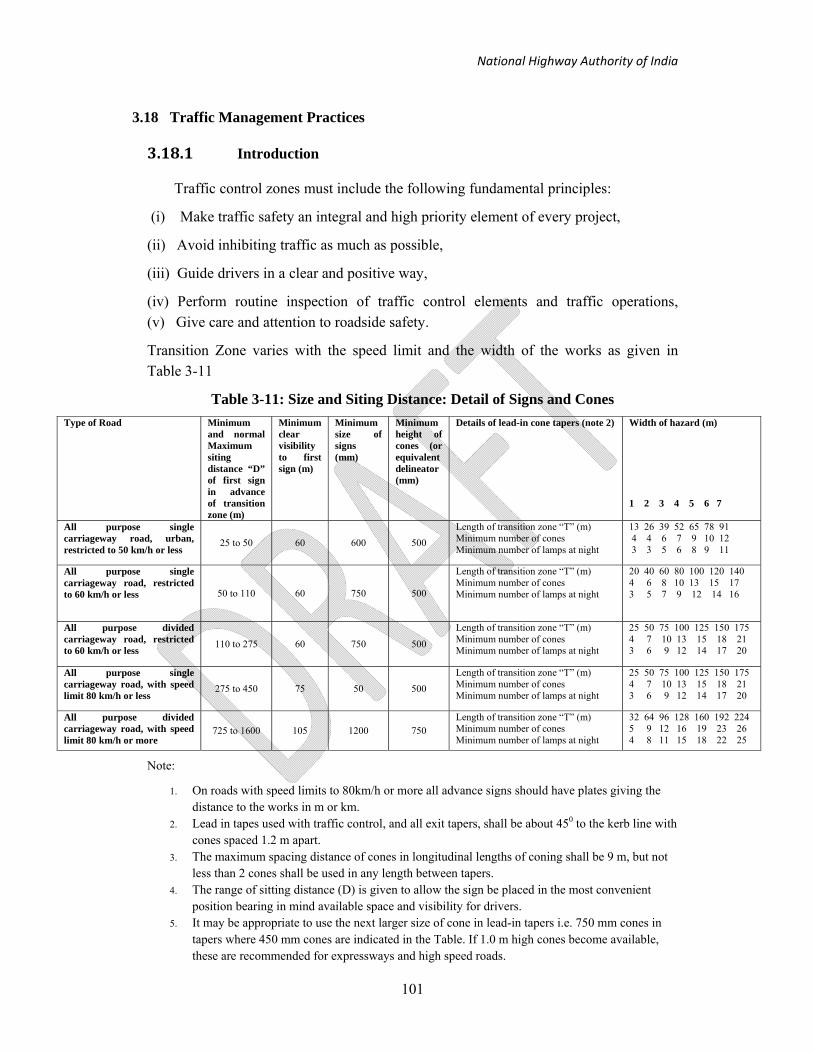
National Highway Authority of India
101
3.18 Traffic Management Practices
3.18.1 Introduction
Traffic control zones must include the following fundamental principles:
(i) Make traffic safety an integral and high priority element of every project,
(ii) Avoid inhibiting traffic as much as possible,
(iii) Guide drivers in a clear and positive way,
(iv) Perform routine inspection of traffic control elements and traffic operations, (v) Give care and attention to roadside safety.
Transition Zone varies with the speed limit and the width of the works as given in Table 3-11
Table 3-11: Size and Siting Distance: Detail of Signs and Cones Type of Road Minimum
and normal Maximum siting distance “D” of first sign in advance of transition zone (m)
Minimum clear visibility to first sign (m)
Minimum size of signs (mm)
Minimum height of cones (or equivalent delineator (mm)
Details of lead-in cone tapers (note 2) Width of hazard (m) 1 2 3 4 5 6 7
All purpose single carriageway road, urban, restricted to 50 km/h or less
25 to 50 60 600 500 Length of transition zone “T” (m) Minimum number of cones Minimum number of lamps at night
13 26 39 52 65 78 91 4 4 6 7 9 10 12 3 3 5 6 8 9 11
All purpose single carriageway road, restricted to 60 km/h or less 50 to 110 60 750 500
Length of transition zone “T” (m) Minimum number of cones Minimum number of lamps at night
20 40 60 80 100 120 140 4 6 8 10 13 15 17 3 5 7 9 12 14 16
All purpose divided carriageway road, restricted to 60 km/h or less
110 to 275 60 750 500
Length of transition zone “T” (m) Minimum number of cones Minimum number of lamps at night
25 50 75 100 125 150 175 4 7 10 13 15 18 21 3 6 9 12 14 17 20
All purpose single carriageway road, with speed limit 80 km/h or less
275 to 450 75 50 500 Length of transition zone “T” (m) Minimum number of cones Minimum number of lamps at night
25 50 75 100 125 150 175 4 7 10 13 15 18 21 3 6 9 12 14 17 20
All purpose divided carriageway road, with speed limit 80 km/h or more
725 to 1600 105 1200 750 Length of transition zone “T” (m) Minimum number of cones Minimum number of lamps at night
32 64 96 128 160 192 224 5 9 12 16 19 23 26 4 8 11 15 18 22 25
Note:
1. On roads with speed limits to 80km/h or more all advance signs should have plates giving the distance to the works in m or km.
2. Lead in tapes used with traffic control, and all exit tapers, shall be about 450 to the kerb line with cones spaced 1.2 m apart.
3. The maximum spacing distance of cones in longitudinal lengths of coning shall be 9 m, but not less than 2 cones shall be used in any length between tapers.
4. The range of sitting distance (D) is given to allow the sign be placed in the most convenient position bearing in mind available space and visibility for drivers.
5. It may be appropriate to use the next larger size of cone in lead-in tapers i.e. 750 mm cones in tapers where 450 mm cones are indicated in the Table. If 1.0 m high cones become available, these are recommended for expressways and high speed roads.

National Highway Authority of India
102
Longitudinal and Lateral Buffer Zone varies with the speed limit as given in Table 3-12
Table 3-12: Buffer Zone Safety Clearances*
Speed restriction
(km/h)
Minimum longitudinal buffer zone (L) (m)
Minimum lateral buffer zone (S) (m)
50 or less 5.0 0.5
60 15 0.5
80 30 1.2
100 60 1.2
120 120 1.2
*based on UK Standards
Where an advisory speed limit is in operation, use it (rather than the mandatory speed limit) to determine the minimum longitudinal and lateral buffer zone safety clearances. Whenever traffic speeds are to be reduced, the method must be agreed in advance with the road authority. Site Engineer should consider advising emergency services of the location and duration of the works.
Working space and safety zones must be provided when personnel are present, but when a site becomes unoccupied it may be possible to make it smaller. This will make it less of an obstruction to traffic. However, if pedestrians are diverted into the carriageway, a safety zone must be provided at all times between the outer pedestrian barrier and the traffic.
Where the road width is so restricted as to prohibit the provision of the appropriate
lateral buffer safety clearance detailed in Table 3-12, and diversion of traffic would be
impractical, traffic speeds must be reduced to less than 15 km/h and an agreed safe
method of working imposed on the site. This method of working should preclude
working in the safety zone wherever possible. It must be decided in advance of the
works. It is also advised that it should be recorded in writing.

National Highway Authority of India
103
3.18.2 Basic Layout
a. Though each construction zone will pose unique problems there is a basic layout that should be followed for all schemes but that will need to be amended within the guidelines set out in these guidelines. These will be influenced by:
(i) Environment; rural; urban;
(ii) type of carriageway such as single lane, two lane, four lanes, multi lanes, divided carriageway;
(iii) Traffic volume and speed with and without work in progress on road; (iv) type of traffic such as mixed or segregated;
(v) Available sight distance in construction zones; and
(vi) Mobility of work zone, that is, for minor pot hole repairs, lane marking etc, the workers and equipment may move along the road.
b. Figure 3-29 shows the basic layout that would permit two-way flow of traffic pass the working zone. The road width must be at least 7 m for two way traffic to ensure that problems for buses and Lorries are minimized. It should be noted that pedestrians are retained on the existing footway. It should be noted that where the working zone is long, cyclists can experience problems and this should also be taken into account. Temporary markings and signage should be used as shown in Figure 3-28.
c. On the roads with no buses or goods vehicles and low flows of vulnerable road users, width of 5.5m could be acceptable but two-way working would not be possible. In this case the cones should be used to reduce the carriageway to not more than 3.7 m and traffic should be controlled by one of the methods given below:
i) The minimum width for one-way traffic is 3.25 m with an absolute minimum of 3 m. As the basic layout should be used in all cases, including lightly used roads in housing areas where there are only cars and other light vehicles, in these special circumstances, the minimum width may be reduced to 2.75 m with an absolute minimum of 2.5 m.
ii) In cases where a traffic control zone may affect an adjacent railway crossing and there is a chance that traffic may block back across the railway line the railway authorities should be informed. It may be necessary to put in place additional safe guards through the use of additional staff to monitor traffic at the railway and to ensure that at no time does traffic wait on the crossing itself.
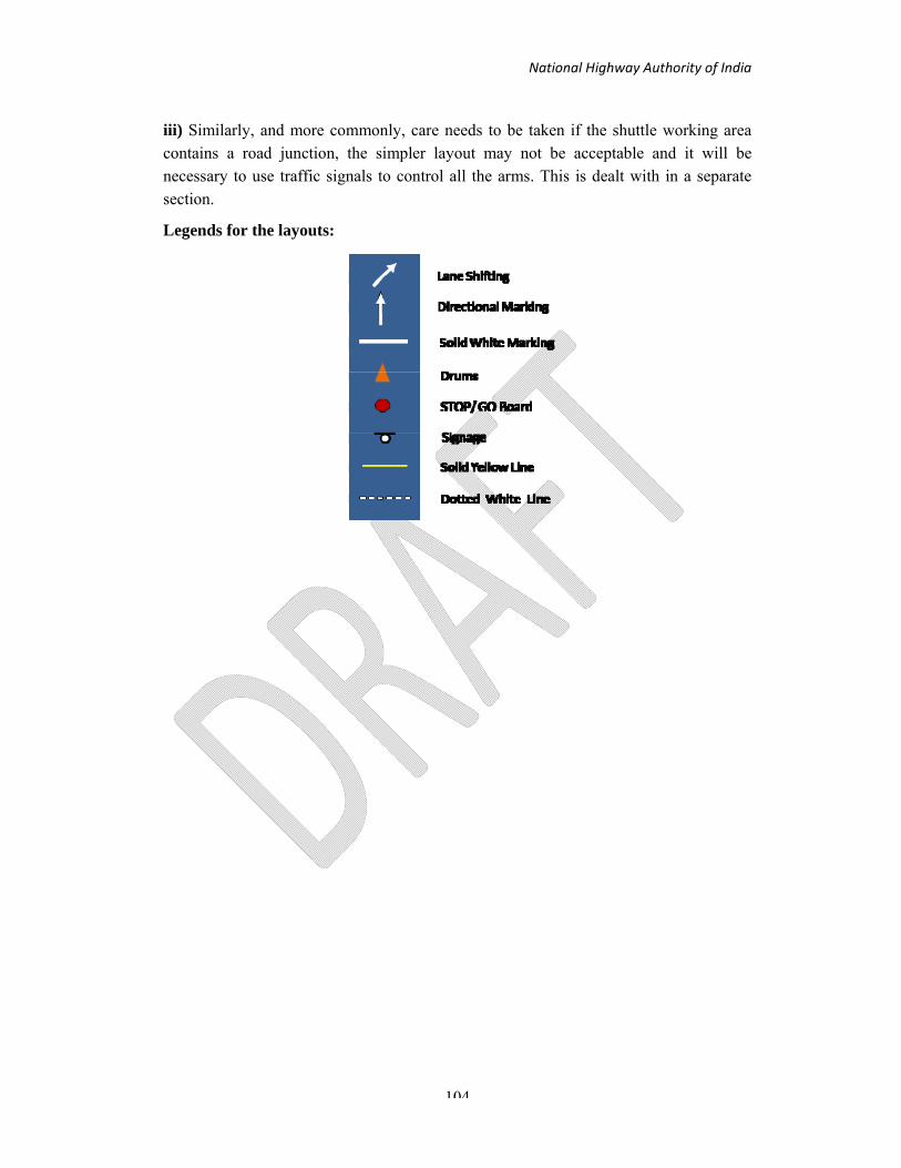
National Highway Authority of India
104
iii) Similarly, and more commonly, care needs to be taken if the shuttle working area contains a road junction, the simpler layout may not be acceptable and it will be necessary to use traffic signals to control all the arms. This is dealt with in a separate section.
Legends for the layouts:

National Highway Authority of India
105
Types of lane Closures and Locations of Work
1 Near Carriageway
2 Shoulder
3 Left Lane
4 Intermediate Lane
5 Right Lane
6 Multi Lanes
7 Median
8 Entire Carriageway

National Highway Authority of India
106
3.18.3 Variations on the Basic Layout
a. Give and take system: Figure 3-30 illustrates the Give and Take system of shuttle working. This is intended for low flows and very low volumes of Lorries and no buses. The following conditions must apply:
- total two -way traffic flow of less than 400 veh/hour ;
- less than 20 lorries/hour;
- speed limit is 50 km/h or less and
- drivers approaching from either direction can see both ends of the site.
b. Priority signs: As flows and the difficulties of the site increase, enhanced systems are more appreciable. Figure 3-31 illustrates the next stage; under traffic control by priority signs the following condition applies:
- total two-way traffic flow of less than 850 veh/hour
- drivers approaching from either direction can see through the site from a point 60 m from their transition zone to a point 60 m beyond their termination zone (coned area), for roads with a 50 km/h speed limit, on higher speed roads, the appropriate clear visibility distances are
- 70m on 60 km/h roads;
- Not applicable above this speed limit.
In Indian conditions, its use is not recommended on higher speed roads.
Priority must be given to either:
- The unobstructed vehicle lane; or
- Vehicles going up a steep gradient
c. Stop/Go boards or flags: Figure 3-32 indicates the layout for the use of STOP/GO boards by flagmen. Table 3-13 sets out the conditions for their use.

National Highway Authority of India
107
Note: 1) The sign boards need to face the oncoming traffic
2) See Table 3-2 for Taper Length
3) Traffic cones are interchangeable with Drums/Traffic Cylinders
Figure 3-29: Basic Layout

National Highway Authority of India
108
Note: 1) The sign boards need to face the oncoming traffic
2) See Table 3-2 for Taper Length
3) Traffic cones are interchangeable with Drums/Traffic Cylinders
Figure 3-30: Traffic control by Give and Take system

National Highway Authority of India
109
Note: 1) The sign boards need to face the oncoming traffic
2) See Table 3-2 for Taper Length
3) Traffic cones are interchangeable with Drums/Traffic Cylinders
Figure 3-31: Traffic control by Priority Signs

National Highway Authority of India
110
Note: 1) The sign boards need to face the oncoming traffic
2) See Table 3-2 for Taper Length
3) Traffic cones are interchangeable with Drums/Traffic Cylinders
Figure 3-32: Traffic control by STOP /GO Board

National Highway Authority of India
111
Note: 1) The sign boards need to face the oncoming traffic
2) See Table 3-2 for Taper Length
3) Traffic cones are interchangeable with Drums/Traffic Cylinders
Figure 3-33: Traffic Control by portable traffic signals

National Highway Authority of India
112
Table 3-13: Maximum Traffic Flows for Length of Site
Site Length
(m)
Maximum two- way flow
Vehicle/ hour Vehicles/3 minutes 100 1400 70 200 1250 63 300 1050 53 400 950 47 500 850 42
3.18.4 Portable Traffic Signals
a) Portable Traffic Signals for traffic control can be used at most sites that have a length of 300m or less. However, it should be ensured that the exit from the restricted length of road is not blocked. Otherwise tailbacks will occur which will stop traffic travelling in the opposite direction from moving when the lights change to green.
b) Under no circumstances should portable traffic signals be used at works that straddle railway level crossings, nor to control road traffic within 50 m of a level crossing equipped with twin red light traffic signals.
c) If it is considered that portable traffic signals used elsewhere may cause road traffic to block back to a level crossing, railway management must be consulted before work starts. The solution will probably be to move the traffic control to a point on the side of the crossing opposite the works so that traffic can be stopped before reaching the crossing. The portable traffic signals must be controlled manually. The crossing’s own road traffic signals and advance warning and informatory signs should remain clearly visible to approaching vehicle drivers.
d) The road authority and traffic police must be informed when Portable Traffic Signals are going to be used. Authorization will be required if these signals are to be used at road junctions.
e) The requirements for setting out the signs, cones and portable traffic signals are given in Table 3-11. Table 3-12 gives the dimensions of the Buffer Zone Safety Clearances. Figure 3-33 shows the layout of working zone and traffic control by portable traffic signals.

National Highway Authority of India
113
f) The traffic signal timings must be correctly set up to correspond to the length of the works and the speed of the traffic past the site. The detectors must be tested, which are sometimes provided on the signals, to make sure that they are working properly before they are used.
g) As back up, Stop/Go boards should be available in case the Portable Traffic Signals break down.
3.18.5 Works on Footways - Alternative Way for Pedestrians
1. An alternative safe route for pedestrians must be provided if it is necessary to close a footway or part of a footway. Additional equipment may be required to do this. Pedestrian access to property must always be ensured. Temporary pedestrian ways should never be less than 1 m wide and, wherever possible, they should be 1.5 m or more in width.
2. It must be ensured that pedestrians are not diverted onto an unguarded carriageway. If the temporary footway is in the carriageway, the approach should be properly guarded and provided with signs. The lateral buffer safety clearance (S) of the safety zone must be on the traffic side of the pedestrian barriers. These clearances are shown in Table 3-12 and an illustration of how to put them into practices is shown in Figure 3-34. The signages and barricades should be in place before the footway is blocked.
3. Exceptionally, the use of the other footway may be acceptable in some quiet roads, but if this option is selected the alternative route must be safe to use, and the needs of children and of people with disabilities must be taken into account.
3.18.6 Pedestrian Safety
1. It should be ensured that there is no danger to pedestrians from falling objects or sharp edges and they will not fall over or bump into anything. Scaffolding be marked with white bands at eye level and allow at least 2.1 m head room. 2. Kerb ramps or raised footways should be provided to help blind, poorly sighted, elderly and disabled people and for those with prams or wheelchairs.
Traffic calming devices like rumble strips and speed humps must be used near pedestrian crossing areas to ensure pedestrian safety,

National Highway Authority of India
114
3.18.7 Pedestrian Barriers
a. Pedestrian barriers should be used to mark out any temporary footway. A rigid barrier must always be used to protect pedestrians from traffic, excavations, plant or materials. Place road danger lamps at the end of the barriers at night. Portable pedestrian barriers, which may include mesh, should be reasonably rigid and have:
- a hand rail fixed at between 1.0 m and 1.2 m above ground level, which should be reasonably smooth and rigid for pedestrians to hold to obtain guidance and some measure of support;
- a visibility panel at least 150 mm deep which may be integral with the hand rail or if separate must be fixed so that its upper edge is a minimum of 0.9 m above ground level. Visibility panels of yellow, white or orange colours are best for detection by partially sighted people, while the red and white rail gives a good contrast and provides interchangeability with traffic barriers ; and
- a tapping rail (for blind people with a white stick) of min depth 150 mm with a lower edge at ground level or up to a maximum height of 200 mm above the ground.
b. Alternatively, when covers are to be removed from underground chambers or manholes and someone will always be there, a barrier with a handrail fixed no lower than 0.8m above ground level will be satisfactory. In this case the barrier must be large enough to enclose the opening and its cover.
3.18.8 Barriers for Visually Impaired
It should be ensured that the barriers can be detected easily by a visually impaired person using a cane stick.
3.18.9 Deep Excavations
If excavations are deeper than 1.2 m, stronger barricades will be required (Type IV).

National Highway Authority of India
115
3.18.10 Safety Zones
A safety zone is provided in the carriageway if the works are closer to the Kerb than the width of the Lateral Buffer Safety Clearance (S) as given in Table 3-12. Use the basic layout in Figure 3-29 to help with the approach signing and guarding of the safety zone.
3.18.11 Pedestrian Crossings
If the works are on or near formally marked pedestrian crossings, care must be taken to avoid confusing pedestrians. Clear guidance must be given as to where they are expected to cross while the works are ongoing.
3.18.12 Works at Junctions
The two-way traffic should be kept flowing past the works if possible. If this is not possible, a diversion route may be required and should be identified by the Road Authority.
Men at Work signs with arrow plates will be required on the main route if the works are located on a side road. (Refer Figure 3-35)
Figure 3-36 shows on or near the far side of a junction. At works like these the taper of cones should be taken up to the approach side of the junction but that any cones near the junction mouth help drivers turn left smoothly. Table 3-11 gives the dimensions D and T and Table 3-12 dimensions of the safety zone.

National Highway Authority of India
116
Note: 1) The practice shown in figure above must be followed for all the TMPs where the work is going on footways
2) Traffic cones are interchangeable with Drums/Traffic Cylinders
Figure 3-34: Works on footways

National Highway Authority of India
117
3.18.13 Works on Construction of Additional Carriageway
The improvement of existing 2-lane carriageway to 4/6 lane divided carriageway facility on National Highway is a major project activity. The planning of traffic and safety management should be carefully planned in advance before taking up the execution of the project, preferably with the advice of a traffic expert. There could be two situations requiring different plan for traffic control.
3.18.13.1 The Central line of the road shifted (eccentric widening)
While constructing the additional carriageway, the centre line of new road/highway gets shifted to a new location. It would have two stages of construction:-
a) The new carriageway shall be constructed in the first stage, adjacent to the existing one and the shoulder in between would become part of the central median of the improved divided carriageway facility. The traffic would continue to ply in both directions on the existing carriageway and an approached diversion would be taken out of the works zone for the movement of construction and supervision vehicles. Figure 3-37 shows a typical layout of the signage system. The location of signs for ‘works traffic’ shall be governed by the location of base camp. The construction zone of new carriageway shall be properly barricaded either by reflectorised delineators or type III barricades or plastic barricades.
b) In the second stage of improvement, the strengthening of the existing carriageway shall be taken up and the traffic would be allowed on the newly constructed carriageway. This would involve crossing of the traffic from existing to the new carriageway. This would involve crossing of the traffic from existing to the new carriageway and then again from the new carriageway to old carriageway. Figure 3-38 shows the layout of signs and traffic control devices for this stage.
3.18.13.2 No shift in central line of the road (co-centric widening)
This activity would be mostly required to be taken up in the stretches of the road/highway passing through built up portions where there may be constraints of land availability. At such locations service roads would also be necessarily constructed for the segregation of the local traffic.

National Highway Authority of India
118
Typically it would have three stages
1. Stage I shall be construction of service roads or diversion road and the traffic moving on the existing carriageway in both directions. The typical layout of signs and control measures shall be, as shown in Figure 3-39.
2. Stage II of the construction activity shall be strengthening of the existing carriageway and the construction of the median. The traffic shall move in one direction only on the service /diversion road constructed on both sides in stage I. The layout for signs and traffic control devices for this stage should be as shown in Figure 3-40.
3. In stage III, the work zone shall be shifted to take up the co-centric widening to the adjacent stretch of the road/highway. Figure 3-41 shows the layout for signs and traffic control devices for this stage.

National Highway Authority of India
119
Note: 1) The sign boards need to face the oncoming traffic
2) Traffic cones are interchangeable with Drums/Traffic Cylinders
Figure 3-35: Works at road junctions

National Highway Authority of India
120
Note: 1) The sign boards need to face the oncoming traffic
2) Traffic cones are interchangeable with Drums/Traffic Cylinders
Figure 3-36: Works on or near the far side of a junction
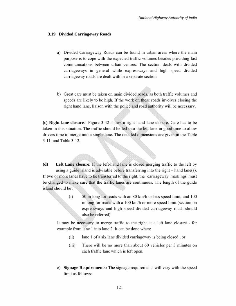
National Highway Authority of India
121
3.19 Divided Carriageway Roads
a) Divided Carriageway Roads can be found in urban areas where the main purpose is to cope with the expected traffic volumes besides providing fast communications between urban centres. The section deals with divided carriageways in general while expressways and high speed divided carriageway roads are dealt with in a separate section.
b) Great care must be taken on main divided roads, as both traffic volumes and speeds are likely to be high. If the work on these roads involves closing the right hand lane, liaison with the police and road authority will be necessary.
(c) Right lane closure: Figure 3-42 shows a right hand lane closure. Care has to be taken in this situation. The traffic should be led into the left lane in good time to allow drivers time to merge into a single lane. The detailed dimensions are given in the Table 3-11 and Table 3-12.
(d) Left Lane closure: If the left-hand lane is closed merging traffic to the left by using a guide island is advisable before transferring into the right – hand lane(s). If two or more lanes have to be transferred to the right, the carriageway markings must be changed to make sure that the traffic lanes are continuous. The length of the guide island should be :
(i) 50 m long for roads with an 80 km/h or less speed limit, and 100 m long for roads with a 100 km/h or more speed limit (section on expressways and high speed divided carriageway roads should also be referred).
It may be necessary to merge traffic to the right at a left lane closure - for example from lane 1 into lane 2. It can be done when:
(ii) lane 1 of a six lane divided carriageway is being closed ; or
(iii) There will be no more than about 60 vehicles per 3 minutes on each traffic lane which is left open.
e) Signage Requirements: The signage requirements will vary with the speed limit as follows:

National Highway Authority of India
122
Table 3-14 : Signage Requirements
Speed Limit Signage Requirements
50 Km/h As shown in Figure 3-42 and Figure 3-43 except that distance plates may be omitted
60 Km/h As shown in Figure 3-42 and Figure 3-43
80 Km/h or more
As shown in Figure 3-42 and Figure 3-43 but with an extra Lane closed to traffic sign added on each side of the carriageway to give the sequence of signs on the right of this page.

National Highway Authority of India
123
Note: 1) The sign boards need to face the oncoming traffic
2) Traffic cones are interchangeable with Drums/Traffic Cylinders
Figure 3-37: Layout of signs for 4-laning with shift in centre line

National Highway Authority of India
124
Note: 1) The sign boards need to face the oncoming traffic
2) Traffic cones are interchangeable with Drums/Traffic Cylinders
Figure 3-38: Layout of signs and control devices for change in carriageway usage

National Highway Authority of India
125
Note: The sign boards need to face the oncoming traffic
Figure 3-39: Co-centric widening: Stage I – construction of new lanes

National Highway Authority of India
126
Note: The sign boards need to face the oncoming traffic
Figure 3-40: Co-centric widening: Stage II – strengthening of existing carriageway
and median construction
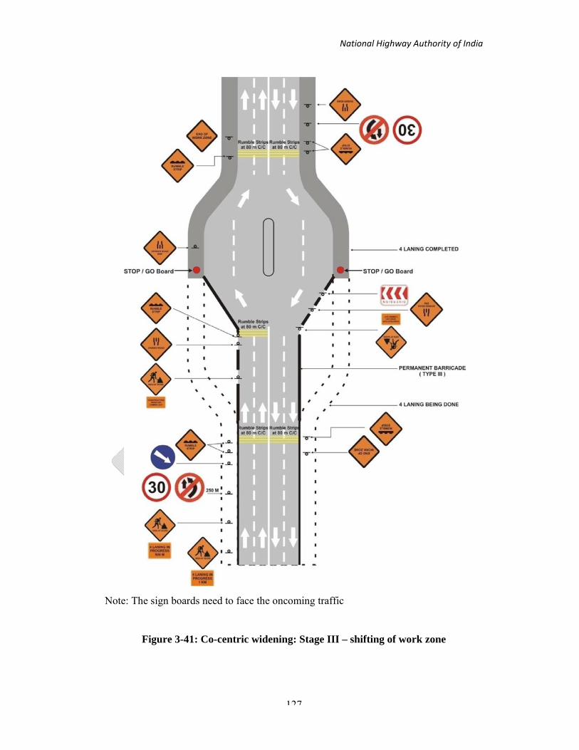
National Highway Authority of India
127
Note: The sign boards need to face the oncoming traffic
Figure 3-41: Co-centric widening: Stage III – shifting of work zone

National Highway Authority of India
128
f) Setting out : Table 3-11 gives dimensions D and T and Table 3-12 for the dimensions of the safety zone.
g) Other planning aspects - execution of maintenance operations: Minor maintenance operations should be confined to small lengths, at a time say 30 m, or so, on half the pavement width, leaving the other half for use by traffic. The basic layout and its variations should be used in all cases to ensure optimum safety during these operations including:
(i) Repairing the edges of the carriageway, shoulders, cleaning out drains, cutting grass etc, where carriageway is basically not affected. Before starting the work, all warning signs and traffic control devices should be placed as discussed above. These should, however, be suitably modified duly keeping in view the size of construction activities and whether it is rural or urban area. A flagman is probably sufficient and should be present during the work duration;
(ii) Repairing small areas of the carriageway, the traffic is to be restricted only due to repairs being carried out as major pothole and / or patch repairs. The work should preferably be so organized that only half width of carriageway is closed at a time and traffic is allowed on other half and traffic control devices as discussed above;
( iii ) While working on the centre of the carriageway such as centre line, lane marking necessitates the traffic to use restricted width on either side. This situation is generally not acceptable and where possible, the work should be undertaken through the closure of half of the carriageway. If this is not possible, the layout shown in Figure 3-44 should be used, with extreme caution.

National Highway Authority of India
129
3.20 Expressway and High Speed Divided Carriageway Roads
An Expressway is a road intended for motorized traffic only where pedestrians, pedal cycles, 2/3 wheelers, small engine motor cycles (mopeds) and rickshaws are not allowed. If these categories are allowed, the road is described as a high speed divided carriageway. These carriageway facilities can have two, three or four lanes in each direction.
Because of the high speed of the vehicles using these roads, extreme care has to be taken when road works are carried out. Stopping distances increase considerably with each 10 km/h increase in speed. Drivers therefore have to have very early warning of restrictions on the road, if accidents are to be avoided. Adequate traffic management measures are, therefore, of great importance to safety. If an accident happens on this type of highway, the consequences can be very serious indeed. The details of the layout of signs and cones for this type of highway are discussed in succeeding paragraphs. The key to symbols used in these illustrations is shown in Figure 3-45, Figure 3-46 and Figure 3-47.
Many traffic management techniques are available for longer duration operation:
(i) Partial closure for work on the carriageway;
(ii) Partial closure for work on shoulders;
(iii) Detour on secondary network;
(iv) Detour on a temporary diversion; and
(v) Speed control

National Highway Authority of India
130
Note: 1) The sign boards need to face the oncoming traffic
2) See Table 3-2 for Taper Length
3) Traffic cones are interchangeable with Drums/Traffic Cylinders
Figure 3-42: Works on dual carriageway roads right hand lane closed for traffic

National Highway Authority of India
131
Note: 1) The sign boards need to face the oncoming traffic
2) See Table 3-2 for Taper Length
3) Traffic cones are interchangeable with Drums/Traffic Cylinders
Figure 3-43: Works on dual carriageway roads, left hand lane closed for traffic
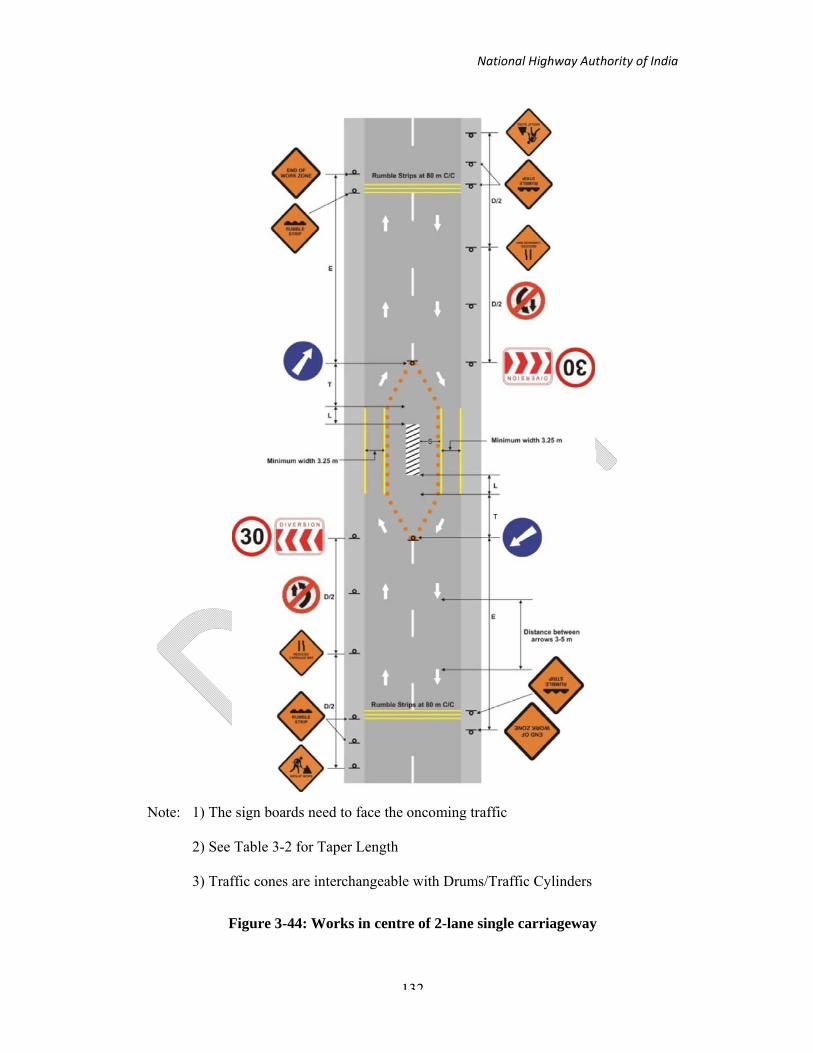
National Highway Authority of India
132
Note: 1) The sign boards need to face the oncoming traffic
2) See Table 3-2 for Taper Length
3) Traffic cones are interchangeable with Drums/Traffic Cylinders
Figure 3-44: Works in centre of 2-lane single carriageway

National Highway Authority of India
133
3.20.1 Four -lane divided carriageways-right lane closure
The basic layout for a four lane divided high speed road is similar to those shown in Figure 3-42 and Figure 3-48. Great care has to be taken in this situation. The traffic should be led into the left lane in good time to allow drivers time to merge into a single lane. Location of signs should be so given in Figure 3-48 and details of 'B' and 'C' as per Figure 3-45.
3.20.2 Four -lane divided carriageways-left lane closure
If the left lane is closed, normally traffic should be merged to the left by using a guide before transferring into the right - hand lane(s) (Figure 3-43 and Figure 3-49). If two or more lanes have to be transferred to the right, the carriageway markings must be changed to make sure that the traffic lanes are continuous. The length of the guide island should be:
- 50 m long for roads with 80 km / h or less speed limit; and 100 m long for roads with a 100 km/h or more speed limit.
If merging traffic to the right at a left -hand lane closure is required (for example, from lane 1 into lane 2) this can be done when :
- lane 1 of a six lane divided carriageway is being closed; or
- there will be no more than about 60 vehicles per 3 minutes on each traffic lane which is left open ( 1200 vehicles/hour for each traffic lane open).
3.20.3 Four-lane divided carriageways - carriageway closure with diversion to opposite carriageway
On occasions it may be necessary to close-one carriageway completely over a distance for major carriageway repairs or resurfacing. This can only be done by using (or specially constructing) emergency crossing points through the median and diverting all the traffic in both directions onto a single lane in opposite directions on one carriageway. This does reduce capacity, and is likely to cause some delays for motorists. The illustration shown in Figure 3-50 shows the procedure for this diversion.
Setting out : Table 3-11 gives the dimensions for D and T and the dimensions of the safety zone are given in Table 3-12.

National Highway Authority of India
134
3.21 Six-lane Divided Carriageways and Expressways
These roads are often carrying very high traffic volumes. It therefore, becomes important to avoid reducing the capacity of the road. As more road space is available than on a four lane divided carriageway, the works can be carried out with only about one third loss of capacity. This would be achieved by a contraflow arrangement. Closing lanes without providing a contraflow should only be done during light traffic flows.
3.21.1 Left and centre lanes closed
This arrangement is shown in detail in the illustration in Figure 3-51.
3.21.2 Right and centre lanes closed
This arrangement is shown in detail in the illustration in Figure 3-52.

National Highway Authority of India
135
Figure 3-45: Detail of Traffic cones (1)

National Highway Authority of India
136
Figure 3-46: Detail of Traffic cones (2)

National Highway Authority of India
137
Figure 3-47: Detail of Traffic cones (3)

National Highway Authority of India
138
Note: 1) The sign boards need to face the oncoming traffic
2) See Table 3-2 for Taper Length
3) Traffic cones are interchangeable with Drums/Traffic Cylinders
Figure 3-48: Expressway without hard shoulder. Lane adjacent to median closed
for traffic
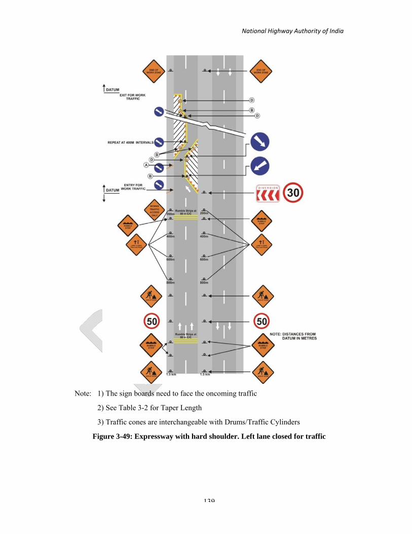
National Highway Authority of India
139
Note: 1) The sign boards need to face the oncoming traffic
2) See Table 3-2 for Taper Length
3) Traffic cones are interchangeable with Drums/Traffic Cylinders
Figure 3-49: Expressway with hard shoulder. Left lane closed for traffic

National Highway Authority of India
140
3.21.3 Segregated contraflow with buffer zones (Primary hard shoulders used)
This arrangement is shown in detail in the illustration in Figure 3-53. This is used on roads with a full lane-width emergency hard shoulder. It requires the use of the opposite carriageway for contraflow of one lane. Only two lane traffic is provided for through the road works with the nearside lane being diverted onto the hard shoulder. The offside lane is closed and the middle lane diverted onto the opposite carriageway that also accommodates two lanes of traffic in the opposite direction. It provides two working lanes plus a buffer lane for the safety of the workforce. This arrangement can only be used if there is a hard shoulder capable of taking heavy traffic, or if one is provided as part of the works.
3.21.4 Segregated contraflow with buffer zones (Both hard shoulders used)
This arrangement is shown in detail in the illustration in Figure 3-54 and is used on roads with a full lane-width emergency hard shoulder. It requires the use of the opposite carriageway for contraflow of one lane. Two lanes are provided for traffic on the primary carriageway with three lanes provided in the opposite direction by using the hard shoulder. It provides two working lanes plus a buffer for the safety of the workforce. This arrangement can only be used if there is a hard shoulder capable of taking heavy traffic, or if one is provided as part of the works.
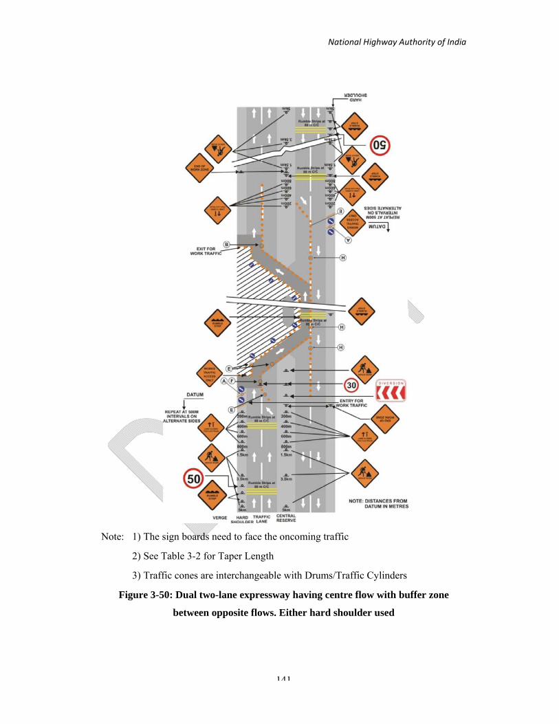
National Highway Authority of India
141
Note: 1) The sign boards need to face the oncoming traffic
2) See Table 3-2 for Taper Length
3) Traffic cones are interchangeable with Drums/Traffic Cylinders
Figure 3-50: Dual two-lane expressway having centre flow with buffer zone
between opposite flows. Either hard shoulder used
National Highway Authority of India
142
3.22 Detour via Secondary Network
a. In the rural situations it may be possible to reduce traffic flows past the construction zone by diverting traffic to an existing alternative route, thereby improving safety at the site. However, it is likely that this will be a road of lower category and it is also likely that the increase in traffic flows will bring about an increase of accidents on the alternative route. Residential roads in cities should, if possible, be avoided. It is, therefore, acceptable only with low traffic volumes. In such cases, it causes a lot of inconvenience to the users. Before diverting the traffic to any alternative route it must be ensured that traffic detours:
(i) are compatible with additional traffic in terms of geometric and structural length. These should be improved to the extent possible to have safe and smooth flow of traffic; (ii) have efficient driver information and
(iii) are clearly identifiable throughout.
b. The public in the area affected, and intending road users should be well informed through press and other mass media about the closure/partial closure of the road and the alternatives for through traffic.
c. Guidance regarding the diversion of traffic to the alternative route must be provided at the appropriate road intersections on either side of the section with the construction zone so that it is possible for the through traffic to divert. This must be done with suitable warning, regulatory and guide signs at appropriate locations to suit the site requirements. The warning sign of ‘Men at Work’ must be placed before the intersection, for approaching traffic, together with a supplementary plate stating ‘ROAD AHEAD CLOSED’ and with the distance to the hazard. There should also be a diversion sign, indicating the turn to be taken. Again it must be emphasized that once traffic is diverted onto the alternative route, all junctions along the route must be provided with signages until the original route is rejoined. If space to site new signs is limited, the use of a symbol is encouraged. The signs at the start of the diversion would state “for diversion follow symbol”, which should then be continued until the original route is rejoined. It is, of course, possible to use different signed routes for the different directions of flow to reduce problems along the alternative routes.
d. At the intersection where the diversion starts, and if the road is fully closed, the use of the permanent type barricade (Type III) is recommended. Suitable 'Chevron' signs and 'Diversion' sign should also be provided at this location for the guidance of the approaching traffic. A watchman should invariably be present at these barricades. A small opening should be provided, if need be, at the extreme edge of the carriageway, at this location. This should normally be kept closed with a double row of painted tar drums. These drums should be removed only for permitting the vehicle for construction and supervision, to pass each time and be put back in position immediately thereafter.

National Highway Authority of India
143
At night, lanterns with red light should be placed at the drums for delineation. Suitable direction and destination signs should also be provided at appropriate locations for the guidance and smooth flow of traffic through the alternative route. The detour 'arrow' signs should also be used at sharp turns on the diversion. Typical arrangements according to the above plan are illustrated in Figure 3-55.
Alternative routes are more likely in urban areas and at confined sites it may be necessary to utilize the technique to permit the work to be undertaken at all. However, there are similar safety implications of diverting large volumes of traffic in choosing the alternative routes and in providing signages.

National Highway Authority of India
144
Note: 1) The sign boards need to face the oncoming traffic
2) See Table 3-2 for Taper Length
3) Traffic cones are interchangeable with Drums/Traffic Cylinders
Figure 3-51: Dual three lane expressway with left and centre lane closed

National Highway Authority of India
145
Note: 1) The sign boards need to face the oncoming traffic
2) See Table 3-2 for Taper Length
3) Traffic cones are interchangeable with Drums/Traffic Cylinders
Figure 3-52: Dual three lane expressway with right and centre lane closed on one
carriageway

National Highway Authority of India
146
Note: 1) The sign boards need to face the oncoming traffic
2) See Table 3-2 for Taper Length
3) Traffic cones are interchangeable with Drums/Traffic Cylinders
Figure 3-53: Dual three lane expressway having segregated contraflow with buffer
zones - primary hard shoulders used

National Highway Authority of India
147
Note: 1) The sign boards need to face the oncoming traffic
2) See Table 3-2 for Taper Length
3) Traffic cones are interchangeable with Drums/Traffic Cylinders
Figure 3-54: Dual three lane expressway having segregated contra flow with buffer
zones - both hard shoulders used

National Highway Authority of India
148
3.23 Temporary Diversions
Where the construction zone would close the road completely, the remaining carriageway space would be insufficient for the traffic and create large delays, and there is no suitable alternative route, it will be necessary to construct a temporary carriageway for all or part of the traffic. This is most common situation in the cases of any major or reconstruction of cross drainage works and of pavement failure due to, for example, floods.
The temporary carriageway must satisfy the following requirements:
i. It should have smooth horizontal and vertical profile with smooth vertical and horizontal and vertical profile with smooth vertical and horizontal curves.
ii. It should not get overtopped by flood or drainage discharges under any conditions
iii. It should have adequate capacity to cater to the expected traffic
iv. It should be dust free and shoulder ensure clear visibility at all times of day and night;
v. Barricading should be provided to prevent construction material falling on the diversion.
This requires that some of the existing work practices and procedures are changed or abolished. For example, any separate area for stockpiling of construction material on or very near carriageway will have to be discontinued. The present practice of exposing the workman to traffic while carrying out works in the centre of the carriageway must be discontinued.
Figure 3-56 shows the layout for sign and traffic control devices for temporary diversions.

National Highway Authority of India
149
Note: The sign boards need to face the oncoming traffic
Figure 3-55: Layout of signs for road closed with detour

National Highway Authority of India
150
Note: 1) The sign boards need to face the oncoming traffic
2) Traffic cones are interchangeable with Drums/Traffic Cylinders
Figure 3-56: Layout of signs and control devices for road closed with diversion

National Highway Authority of India
151
3.24 Speed Control
In most cases, work on the existing road encroaches on the running lanes and shoulders and, therefore, causes a hindrance to the normal flow of traffic. In such situations the closing of lanes is a normal practice. Its consequences on the level of service, resulting delays and/or congestion should be first evaluated. Any alternative strategy (e.g. detour, etc.) should also be evaluated. However, in any traffic management at road works situation, traffic using lanes which are to be closed should have time and space for merging with traffic in the next parallel lane as well as to transfer to provisional or altered lanes or both. Normally this requires some reduction in speed, enough advance information to enable safe merging, but it should be kept to a minimum if successful merging is to be achieved. The critical information for approaching drivers is as to which lane is blocked so that they can begin moving into the open lane(s) at an early stage.
It is preferable to close first the fastest lane and not the slowest, even if the work zone occupies the latter. The reason for this is that slow moving commercial vehicles are more reluctant to give way than the more maneuverable cars which use the fast lane. In this method a reduction in speed is also more easily achieved. If the work zone occupies a centre lane of a multi - lane road, it is recommended to close the adjacent lane to avoid an 'island' situation.
Speed Control should often extend through the work site and will depend on the volume of traffic and the width of the traffic lanes that it is feasible to permit. Traffic lanes can be reduced to 3.0 m where space is restricted and, if used by cars and light vehicles only may be reduced to 2.75 m with caution. The maximum length of a lane closure would depend upon the traffic volume and number of remaining lanes and normally it should not exceed 5 km where speed control is in operation.
The co-operation of the local police should be sought to the introduction of a temporary but mandatory speed limit, lower than the existing speed limit on the approaches and through the working zone. This may be as low as 50 km/h even for high speed roads, where only one lane is available for traffic. Speed reducing measures such as rumble strips must be installed as explained below (Figure 3-57).

National Highway Authority of India
152
Figure 3-57: Placement of Rumble strips in work zone area

National Highway Authority of India
153
Note: All dimensions are in metres
Figure 3-58: Details of Rumble Strips

National Highway Authority of India
154
3.25 Alternatives for Different work zone Situations for Traffic Management
1. If Construction is going at intersection then its alternatives are
a) Narrow lane and decrease the number of lanes b) Use of temporary by-pass c) Shoulder use for traffic diversion d) If work for short period then do the work
I. At night time II. In weekend
III. Restriction for entry of heavy vehicles IV. Provide rumble strips at the entry of construction zone V. In work zone area, always communicate by speaker to reduce speed you are in
construction area.
2. Work in the centre of two lane single carriageways
(a) Narrow lane
(b) If work for short period then do the work
(i) At night time
(ii) In weekend
(iii) Restriction for entry of heavy vehicles
(c) Shoulder use for traffic diversion
(d) Provide rumble strips at the entry of construction zone
(e) In work zone area, always communicate by speaker to reduce speed you are in construction area.
3. Work on shoulder
(a) Narrow lane and decrease the number of lanes
(b) Paved median used for traffic movement
(c) Both side of traffic movement on one side with road marking.
(d) Stopping & starting at irregular interval, i.e., closure of road for short period
(e) If work for short period then do the work

National Highway Authority of India
155
(i) At night time
(ii) In weekend
(iii) Restriction for entry of heavy vehicles
(f) Provide rumble strips at the entry of construction zone
(g) In work zone area, always communicate by speaker to reduce speed you are in construction area.
(h) Complete closure of shoulder use till construction period
4. Work at the side of single lane carriageway
(a) Narrow lane and decrease the no of lanes
(b) Use of temporary by-pass
(c) Shoulder use for traffic diversion
(d) Completely close the lane and divert the traffic to other side of road
(e) To make temporary structure for movement of traffic on right of ways.
(f) Provide rumble strips at the entry of construction zone
(g) In work zone area, always communicate by speaker to reduce speed you are in construction area.
5. When road is completely closed for long duration of construction
(a) To make temporary (for short duration) and paved shoulder (for long duration) for the traffic movement.
(b) With the help of traffic police, tell the drivers to use alternative route.
6. For flyover construction
(a) Narrow lane and decrease the no of lanes
(b) Use of precast materials
(c) Use of rapid curing materials
(d) Shoulder use for traffic diversion
(e) Provide rumble strips at the entry of construction zone
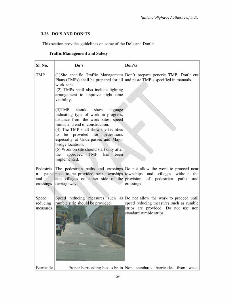
National Highway Authority of India
156
3.26 DO’S AND DON’TS
This section provides guidelines on some of the Do’s and Don’ts.
Traffic Management and Safety
Sl. No. Do’s Don’ts
TMP (1)Site specific Traffic Management Plans (TMPs) shall be prepared for all work zone (2) TMPs shall also include lighting arrangement to improve night time visibility. (3)TMP should show signage indicating type of work in progress, distance from the work sites, speed limits, and end of construction. (4) The TMP shall show the facilities to be provided for pedestrians especially at Underpasses and Major bridge locations. (5) Work on site should start only after the approved TMP has been implemented.
Don’t prepare generic TMP. Don’t cut and paste TMP’s specified in manuals.
Pedestrian paths and crossings
The pedestrian paths and crossings need to be provided near townships and villages on either side of the carriageway.
Do not allow the work to proceed near townships and villages without the provision of pedestrian paths and crossings
Speed reducing measures
Speed reducing measures such as rumble strip should be provided.
Do not allow the work to proceed until speed reducing measures such as rumble strips are provided. Do not use non standard rumble strips.
Barricade Proper barricading has to be in Non standards barricades from waste

National Highway Authority of India
157
s place as per the current guidelines. Indicate specific locations where drums and cones are to be used. Based on the site requirement type of barricade should be specified as per current guidelines.
material should not be used as barricades.
Signages All signages must comply with the specifications in current guidelines and IRC-67:2011.
Don’t use non standard signages.

National Highway Authority of India
158
3.27 PENALTIES
In view of the commitment of Road Construction Agency towards work zone safety, it is
reiterated here that any lapse on part of contractor/Engineer will be viewed very seriously.
For the first lapse of non-life threatening violations, warning to the concerned agencies shall
be issued by the project director and for the first repeat of such non-compliances the 2%
amount of the contractor from its running bill would be withheld as per the provision of
COPA. Subsequent repeat of such non-life threatening lapses would attract a penalty as
provided in Table 3-15. For life threatening lapses by the contractor the very first instance of
such lapse would attract the penalty as given in Table 3-15.

National Highway Authority of India
159
Traffic Management Safety Non-compliance
Table 3-15 : Penalty for non compliance of provisions in Traffic Management and
Safety
1. Traffic management documents
(i) Non compliance of clause of WZRSM (Field compliance of approved TMP)Non compliance to be recorded as per the check list.
(ii) TMPs are not site/section specific (iii)TMPs are not submitted one month
before the scheduled work on site (iv) TMP/drawing does not show the traffic
safety arrangements both for day and night.
(v) TMP does not reflect necessary safety provisions for pedestrians and local residents.
(vi) Contractor is initiating work without the necessary TMP approval in place.
(vii) All road safety devices should be of specification mentioned in current manual & current Road safety products code
For (i) Rs. 1,00,000.00 For each diversion For (ii) Rs. 50,000.00 for each TMP For (iii),(iv) Rs. 10,000.00 for each TMP For (v) Rs. 25,000.00 for each TMP and for (vi) Rs. 50,000.00 for each TMP For (vii) Rs. 50,000.00 for each non compliance
2
Traffic management Field noncompliance
(i) Non compliance of clause of WZRSM(Field compliance of approved TMP)Non compliance to be recorded as per the check list.
(ii) Barricades not as per the specifications in current manual
(iii)General signage not as per the specification in current manual
(iv) Diversion signage not as per current manual
(v) Pavement markings not as per the specification in current manual
(vi) Flagman not as per specification in current manual
(vii) Speed reducing measures ( rumble strips) have not been provided at/near existing highway crossings of other categories, eg: State highway (SH), MDRs, Local Roads
For (ii) to (vi) Rs. 5000.00 for each non compliance and for (vii) Rs.50000.00 for each non- compliance

National Highway Authority of India
160
BOQ for traffic Management Plans
BOQ items for 2 Lane Highway
S. No. Description Unit Quantity Rate Amount
1. Traffic arrangements during construction in accordance with MORTH Specifications Clause 112, IRC:SP:55, IRC-67 and IRC-35 and supplementary technical specifications.
(i) Providing services for safety, control and management of traffic as per Traffic Management and safety plan approved by the Engineer including the provision and availability of Safety, Health and Environment Manager with support staff and the required traffic marshals/flagmen during the construction period
Month
(ii) Provision and maintenance of temporary traffic control devices, multiple usage during construction, including their removal and clearing of debris after the requirement is completed and as directed by the Engineer.
a Cones no.
b Drums no.
c Blinkers no.
d Plastic Barricades no.
e Construction Work Zone Signs no.
Manufacturing, supplying and installation of Cautionary, Mandatory & Chevron Sign boards made out of Class B
m2

National Highway Authority of India
161
sheeting as per IRC-67:2011 fixed on 2mm thick Aluminium sheet or 3mm Aluminium composite material. The front side is to be covered with Retro reflective sheeting conforming to Class B sheeting as per IRC-67:2011 as per approved colour scheme. The board shall be riveted to the back frame of size 25mm×25mm×3mm MS Angle. Boards are to be duly installed on the suitable foundation as per the approved template/direction of Engineer-in-Charge.
e.1 Men at Work sign m2
e.2 Rumble Strip Sign m2
e.3 Reduced Carriageway m2
e.4 Chevron Sign m2
e.5 Compulsory Keep Left Sign m2
e.6 Compulsory Keep Right Sign m2
e.7 Speed Limit Sign (30 kmph minimum)
m2
e.8 End of Work Zone Sign m2
f Traffic Cylinders/Spring Posts no.
g Delineators no.
h Hand Flasher/Batons no.
i Hand Paddles no.
j Portable Variable Message Signs no.
k Safety Helmets/Shoes/Jackets no.
l Traffic Bollards no.
m Convex Mirrors no.

National Highway Authority of India
162
n Solar products no.
o Plastic Mesh fence m
p Temporary fencing m
q Pavement markings m2
r Barricades – Type - I m or no.
s Barricades – Type - II m or no.
t Barricades – Type - III m or no.
u Barricades – Type - IV m or no.
v Set of rumble strips no.
w Roll up signs no.
x Raised Pavement Marker no.
(iii) Provision and maintenance of temporary diversion including temporary cross drainage works as directed by the Engineer in accordance with Sub-clause 112.3 of MORTH Specifications and Supplementary Technical Specifications including dismantling and clearing of debris after the requirement is completed and as directed by the Engineer
m
Note: All the temporary traffic control devices shall be the property of the Contractor and he is to be paid only the multiple usage charges for which the rate is required to be quoted

National Highway Authority of India
163
BOQ items for 4 Lane Highway
S. No. Description Unit Quantity Rate Amount
1. Traffic arrangements during construction in accordance with MORTH Specifications Clause 112, IRC:SP:55, IRC-67 and IRC-35 and supplementary technical specifications.
(i) Providing services for safety, control and management of traffic as per Traffic Management and safety plan approved by the Engineer including the provision and availability of Safety, Health and Environment Manager with support staff and the required traffic marshals/flagmen during the construction period
Month
(ii) Provision and maintenance of temporary traffic control devices, multiple usage during construction, including their removal and clearing of debris after the requirement is completed and as directed by the Engineer.
a Cones no.
b Drums no.
c Blinkers no.
d Plastic Barricades no.
e Construction Work Zone Signs no.
Manufacturing, supplying and installation of Cautionary,
m2

National Highway Authority of India
164
Mandatory & Chevron Sign boards made out of Class B sheeting as per IRC-67:2011 fixed on 2mm thick Aluminium sheet or 3mm Aluminium composite material. The front side is to be covered with Retro reflective sheeting conforming to Class B sheeting as per IRC-67:2011 as per approved colour scheme. The board shall be riveted to the back frame of size 25mm×25mm×3mm MS Angle. Boards are to be duly installed on the suitable foundation as per the approved template/direction of Engineer-in-Charge.
e.1 Men at Work sign m2
e.2 Rumble Strip Sign m2
e.3 Lane Closed Sign (Two Lane road) m2
e.4 Chevron Sign m2
e.5 Compulsory Keep Left Sign m2
e.6 Compulsory Keep Right Sign m2
e.7 Speed Limit Sign (30 kmph minimum)
m2
e.8 End of Work Zone Sign m2
f Traffic Cylinders/Spring Posts no.
g Delineators no.
h Hand Flashers/Batons no.
i Hand Paddles no.
j Portable Variable Message Signs no.

National Highway Authority of India
165
k Safety Helmets/Shoes/Jackets no.
l Traffic Bollards no.
m Convex Mirrors no.
n Solar Products no.
o Plastic Mesh Fence m
p Temporary fencing m
q Pavement markings m2
r Barricades – Type - I m or no.
s Barricades – Type - II m or no.
t Barricades – Type - III m or no.
u Barricades – Type - IV m or no.
v Set of rumble strips no.
w Roll up signs no.
x Raised Pavement Marker no.
(iii) Provision and maintenance of temporary diversion including temporary cross drainage works as directed by the Engineer in accordance with Sub-clause 112.3 of MORTH Specifications and Supplementary Technical Specifications including dismantling and clearing of debris after the requirement is completed and as directed by the Engineer
m
Note: All the temporary traffic control devices shall be the property of the Contractor and he is to be paid only the multiple usage charges for which the rate is required to be quoted

National Highway Authority of India
166
BOQ items for 6 Lane Highway
S. No. Description Unit Quantity Rate Amount
1. Traffic arrangements during construction in accordance with MORTH Specifications Clause 112, IRC:SP:55, IRC-67 and IRC-35 and supplementary technical specifications.
(i) Providing services for safety, control and management of traffic as per Traffic Management and safety plan approved by the Engineer including the provision and availability of Safety, Health and Environment Manager with support staff and the required traffic marshals/flagmen during the construction period
Month
(ii) Provision and maintenance of temporary traffic control devices, multiple usage during construction, including their removal and clearing of debris after the requirement is completed and as directed by the Engineer.
a Cones no.
b Drums no.
c Blinkers no.
d Plastic Barricades no.
e Construction Work Zone Signs no.
Manufacturing, supplying and installation of Cautionary, Mandatory & Chevron Sign boards made out of Class B sheeting as per IRC-67:2011 fixed on 2mm thick Aluminium sheet
m2

National Highway Authority of India
167
or 3mm Aluminium composite material. The front side is to be covered with Retro reflective sheeting conforming to Class B sheeting as per IRC-67:2011 as per approved colour scheme. The board shall be riveted to the back frame of size 25mm×25mm×3mm MS Angle. Boards are to be duly installed on the suitable foundation as per the approved template/direction of Engineer-in-Charge.
e.1 Men at Work sign m2
e.2 Rumble Strip Sign m2
e.3 Lane Closed Sign (Two Lane road) m2
e.4 Chevron Sign m2
e.5 Compulsory Keep Left Sign m2
e.6 Compulsory Keep Right Sign m2
e.7 Speed Limit Sign (30 kmph minimum)
m2
e.8 End of Work Zone Sign m2
e.9 Work Traffic Access Only m2
f Traffic Cylinders/Spring Posts no.
g Delineators no.
h Hand Flashers/Batons no.
i Hand Paddles no.
j Portable Variable Message Signs no.
k Safety Helmets/Shoes/Jackets no.
l Traffic Bollards no.

National Highway Authority of India
168
m Convex Mirrors no.
n Solar Products no.
o Plastic Mesh Fence no.
p Temporary fencing m
q Pavement markings m2
r Barricades – Type - I m or no.
s Barricades – Type - II m or no.
t Barricades – Type - III m or no.
u Barricades – Type - IV m or no.
v Set of rumble strips no.
w Roll up signs no.
x Raised Pavement Marker no.
(iii) Provision and maintenance of temporary diversion including temporary cross drainage works as directed by the Engineer in accordance with Sub-clause 112.3 of MORTH Specifications and Supplementary Technical Specifications including dismantling and clearing of debris after the requirement is completed and as directed by the Engineer
m
Note: All the temporary traffic control devices shall be the property of the Contractor and he is to be paid only the multiple usage charges for which the rate is required to be quoted

National Highway Authority of India
169
4. Safety in Road Construction Works
The contractor shall prepare the method statement for all the activities that he/she intends to perform in order to fulfil his/her contractual obligations, as mentioned in MoRTH Orange Book (2001), ‘The sole responsibility for the safety and adequacy of the methods adopted by the Contractor will, however, rest on the Contractor, irrespective of any approval given by the Engineer’. Before starting any of the activity the contractor shall make sure to get the approval of Construction Supervisory Consultant (CSC). The methodology of road construction would in general be governed by the MoRTH specifications and contract document in specific. The aspects of road construction discussed in following sections shall refer only to those activities that have a significant safety impact on the overall process. The safety aspects related to traffic, workers, and tools and machinery are covered in Units 3, 6 and 7 respectively. Other aspects related to road construction work, which have a no impact on safety, are not included here.
4.1 General
The Contractor shall take all precautions for safeguarding the workers during the course of the construction of the works and abide by all laws, rules and regulations in force governing the worker safety. The overall framework of enhancing the safety can be viewed as per the flow chart given in Figure 4-1. This chart captures clearly various activities and the related safety aspects that are discussed elsewhere in the manual in detail. Each of the activity involves the use of machines/human power under certain work environment that affect the overall safety. This chapter on road construction safety highlights different activities and a list of do’s and don’ts in these activities. It is however important to note that in spite of the best efforts in preventing the accidents from happening, some of them may still occur. The endeavor of the overall road construction safety planning is to minimize the probability of occurrence of the unsafe events.
Methodology and Sequence of Work
Prior to start of the construction activities at site, the Contractor shall, within 28 days after the date of the Letter of Acceptance unless otherwise stipulated in the Contract, submit to the Engineer for approval, the detailed method statement. The method statement shall be submitted in two parts.
The general part of the method statement shall describe the Contractor’s proposals regarding preliminary works, common facilities and other items that require consideration the early stage of the contract. The general part shall include information on:
i) Source of materials like coarse aggregate and fine aggregate, quantity and quality of materials available in different sources;
ii) Source of manufactured materials like cement, steel reinforcement, pre-stressing strands and bearings etc. He shall also submit samples/ test certificates of materials for consideration of the Engineer;
iii) Location of the site facilities such as batching plant, hot mix plant, aggregate processing unit etc;
iv) Details of facilities available for transportation of men/material and equipment

National Highway Authority of India
170
v) Information on procedure to be adopted by the Contractor for prevention and mitigation of negative environmental impact due to construction activities;
vi) Safety arrangement during construction:
Any other information required by the Engineer
The rest of the chapter is presented in four sections. The first section deals with the overall activities involved in road construction and the safety components that need to be addressed. Subsequent sections present the details of related safety aspects of activities in sequence i) site clearance and quarrying ii) earth work, iii) base and subs courses and iv) surface courses.
Figure 4-1 Road construction safety process
1. Site Clearance/Borrow Pit/Quarrying
Road construction safety (Unit 4)
2. Earth work
3. Sub-bases/Base
4. Surfaces: Asphalt/
Pavement Quality Concrete
Traffic Safety (Unit 3)
Electrical and Mechanical
equipment safety
(Unit 7)
Worker safety
(Unit 6)

National Highway Authority of India
171
4.2 Safety aspects in road construction: general
Following are the important issues that need to be taken care of:
1. Worker visibility: Four laning of the NH’s involve the work being performed on roadways that are open to traffic. At the same time, traffic continues to grow and creates more congestion. This combination of more work zones, heavier traffic, and greater reliance on night work results in increased risk for highway workers. All workers should wear high visibility apparel. Worker visibility during dawn or dusk conditions may be enhanced by the use of fluorescent coloured high visibility.
2. Visual and auditory contact of the road worker: Road workers may be exposed to noise from many sources including heavy vehicles, passing traffic and pneumatic drills. Noise may move parts on equipment and machinery may cause bruises, cuts or more serious injuries. Vehicles and heavy equipment can become unstable on slopes or uneven road surfaces. This poses risks not only to the driver, but to other workers in the vicinity. Vehicles may not have a good line of vision when reversing. If not warned, workers behind the vehicle may be seriously injured or even killed. Workers such as motor graders and mower, swather and snowplough operators are often require working alone. Dangerous situations can arise if they are injured or otherwise incapacitated. Hence Visual and auditory contact of the road worker is important. The Worker Visibility Rule requires the use of high-visibility safety apparel by workers who are working within the rights-of-way of Federal-aid highways.
3. Limited work space: The road construction area consists of both temporary work space needed for equipment during construction and the permanent right-of-way required to operate and maintain the traffic safely. During construction, additional temporary work space is required beyond the width of permanent right-of-way to provide room for materials, machinery and two lanes of construction equipment traffic. Landowners are compensated for the use of temporary workspace in addition to the permanent right-of-way.
The amount of temporary work space and permanent right-of-way will vary depending on the size and type of construction, location, community development plans, soil conditions and regulatory requirements. An Enbridge right-of-way representative will provide more specific information during discussions with the landowner.
4. Unsatisfactory barriers between work zone and traffic: There should be satisfactory temporary type barriers between work zone and traffic. This should be ensured by NHAI/CSC.
5. Health Issue: Workplace Health Issues Can Often Be Controlled Though Housekeeping and Maintenance, No matter what the workplace environment, the product, or the service, proper maintenance and good routines are critical to proper safety, and controlling health issues. When it comes to health issues, maintenance is the term that refers to the work that is necessary for keeping the building, equipment, and machinery in working order and safe to use.
Here is a list of some of the more common source on road construction site where excess dust can create a real problem.
• Mines and quarries – dust from coal, flint and silica • Road Construction sites - dust from cement, dry soil, stone and asbestos

National Highway Authority of India
172
• Farming and Agriculture – dust from grain • Carpentry and Joinery – dust from wood
Where dust has a fundamental presence within a particular occupation, workers need to be provided with the correct protective clothing and with breathing respirators if need be. These are much better than dust masks which have often been proved to be relatively ineffective. Employers should also ensure that workers undergo regular health checks which might pinpoint any early signs of illness.
6. Preventing backover: The leading cause of fatalities for workers in work zones is being run over or backed over by vehicles. While we often worry about construction workers being killed by motorists, road workers working behind the barriers in the work zone are at equal risk of being killed by construction vehicles due to their large “blind spots.” Each month, at least one worker is killed by being backed over by a construction vehicle, often a dump truck. These deaths are completely preventable. This section is designed to help you prevent more workers from being killed on the job. Let’s stop back over deaths now!
7. Temporary traffic control: A worksite traffic control plan must be developed which is suited to the job and location. Work on busy highways should be scheduled for off-peak hours. All signals and devices must be delivered to the site in sufficient time for installation.
Traffic control methods must get passing motorist's attention, warn the drivers, slow the driver, guide the driver around the worksite and return the driver to normal traffic.
Traffic control signals must be clearly visible, simple, allow time to understand and respond and be consistent. They include signs, lights, barricades, cones, drums, railings.
8. Working Alone: Where workers are required to work alone a proper plan must be in place. This should include identification of possible risks, means of minimizing the risks and means of seeking assistance should a mishap occur. A regularly scheduled communication system must be in place to alert control centres of possible mishaps.
The MFL Occupational Health Centre also has factsheets and other information on noise, gasoline, diesel, asphalt, coal tar, epoxy resins, working in cold and hot environments, personal protective equipment, vehicle safety, and tool design.
9. Training: Work zone safety training and guidelines to assist with improving highway work zone safety.
Table 4-1 gives the list of equipment used in various stages of road construction process. The safety aspects related to these equipments are discussed in detail in the subsequent sections

National Highway Authority of India
173
Table 4-1Equipment/Processes related various road construction aspects
S. No. Activity Equipment/Process
1 Site Clearance/Borrow pit/quarrying • Crawler or • Pneumatic tyred dozer
2 Earth work: -
Excavation in rock • Hydraulic excavator with rock breaker or Jack hammer operated with air compressor
Marsh excavation • Slurry pump and hydraulic excavator
Removal of earth • Hydraulic excavators
Small excavation • Backhoe loader
Areas where vibrations are prohibited • Silent cracking
3 Bases/Sub-bases
Mixing and pulverising the soil • Rotavator
Spreading the mix • Motor grader
Cleaning the surface • Mechanical broom
Compaction • Smooth wheeled tandem type roller
• Vibratory roller • Pneumatic tyred roller
4 a) Surfaces: asphalt
Surface cleaning • High pressure air jet
Applying tack coat • Self-propelled/Towed asphalt pressure sprayer
Spreading • Self-propelled sensor paver
Compaction • Smooth wheeled tandem type roller, Vibratory roller
b) Surfaces: concrete
Spreading • Fixed or slip-form paver
Vibration • Vibrators

National Highway Authority of India
174
4.3 Site Clearance/Borrow Pits/Quarrying
Borrow pits shall not be dug in the right-of-way of the road. Also it has to be ensured that the borrow area is being placed in the prescribed zone at the site and also ensure about the soil characteristics of the borrow area like slope, ground water level etc.
Site Clearance
Operators may get killed in machine roll-overs. The types of construction plant which are most prone to roll over, and which should be fitted with a roll-over protective structure and a seatbelt to restrain the operator, are:
(a) Wheeled and crawler tractors, loaders and dozers;
(b) Motor graders and scrapers;
(c) Self-propelled rollers and compactors with a weight of 2700 kg or more.
Supplementary Steering Systems. The above plant items should have a steering system such that in the event of the engine stopping the operator is able to steer the machine to a position of safety. If this cannot be achieved, a supplementary steering system should be fitted, if feasible
Quarry Operations
The Contractor shall obtain materials from quarries only after the consent of the Forest Department or other concerned authorities is obtained. The quarry operations shall be undertaken within the purview of the rules and regulations in force.
Substances Hazardous to Health
The Contractor shall not use or generate any materials in the road construction works which are hazardous to the health of persons, animals or vegetation. Where it is necessary to use some substances which can cause injury to the health of workers, the Contractor shall provide protective clothing or appliances to his workers.
Use of Nuclear Gauges
Nuclear gauges shall be used only where permitted by the Engineer. The Contractor shall provide the Engineer with a copy of the regulations governing the safe use of nuclear gauges he intends to employ and shall abide by such regulations. Valid approval for operating nuclear gauge from the appropriate authority is mandatory. However, initiative may be taken to use non-nuclear based equipments.
4.4 Earth work
The contractor shall ensure
i) where any construction building worker engaged in excavation is exposed to hazard of falling or sliding material or article from any bank or side of such excavation which is more than one 1.5 m above his footing, such worker is protected by adequate piling and bracing against such bank or side.

National Highway Authority of India
175
ii) where banks of an excavation are undercut, adequate shoring is provided to support the material or article overhanging such bank.
iii) excavated material is not stored at least 0.65 m from the edge of an open excavation or trench and banks of such excavation or trench are stripped of loose rocks and the banks of such excavation or trench are stripped of loose rocks and other materials which may slide, roll or fall upon a construction building worker working below such bank
iv) metal ladders and staircases or ramps are provided, as the case may be, for safe access to and egress from excavation where, the depth of such excavation exceeds 1.5 m and such ladders, staircases or ramps comply with the IS 3696 Part 1&2 and other relevant national standards.
v) trench and excavation is protected against falling of a person by suitable measures if the depth of such trench or excavation exceeds 1.5 m and such protection is an improved protection in accordance with the design and drawing of a professional engineer, where such depth exceeds 4m.
The Contractor shall ensure that the embankment does not adversely affect the stability of excavation or fills by the methods of stockpiling materials, use of plants or siting of temporary buildings or structures.
Some of the important precautions that the workers need to take while the earthwork operations are in progress are:
Movement of trucks: Trucks sometimes fall over a tip head because the driver backs over the edge or the edge collapses under the weight of the truck. A protective berm or timber baulk should be used. Alternatively, back under the control of a signalman in order to avoid this possibility. Where ground conditions are soft, or the tip head is likely to subside, dump loads back from the edge and get a dozer to move the material over the edge.
Bulldozers: Do’s and Don’ts:
Do – Wherever possible avoid side hill travel. Drive straight up and down slopes. If the machine starts to slide sideways when working across a slope, turn the machine downhill and drop the blade.
Do – If you have to drive down a steep slope, keep a good blade full of spoil in front of the blade on the way down. If dirt is being lost, lowering the blade slightly may help, but lowering it too far brings the danger of overturning.
Do – When you are working on slip clearing, proceed with caution and watch the slope. Further falls may occur.
Do – When clearing trees, watch out for dead branches in tree tops as abrupt contact with a butt may dislodge them.
Do – Avoid obstacles such as rocks or logs. If you are forced to cross them, use extreme caution and change to the lowest gear. Ease up to the break-over point and ease down to minimise the jolt on contact on the other side.
Do – Be careful when working near the edge of banks and ditches or under overhanging material. The vibration and weight of your machine may cause the edge to give way or overhanging material to fall.

National Highway Authority of India
176
Do – Before starting work in a river, check water depths and the bed for holes. Do not work alone in deep water. Another person must be present at all times. Place a buoyed safety line across the river downstream of the work.
Excavators: Do’s and Don’ts–
When excavating trenches, place the excavated material at least 600 mm clear of the edge, where there is no danger of it falling back into or collapsing the side of the trench.
Do – Create a level area to operate from when working on a steep grade. If you cannot do this, avoid swinging your boom downhill any further than necessary and operate your machine slowly to maintain stability.
Do – When travelling up or down a steep slope, place the track sprockets at the rear of the machine. For uphill travel extend the boom and bucket forward, and for downhill travel place them close in, in order to maximize stability and traction.
Do – Watch boom clearance when travelling. Uneven ground may cause the boom to weave or collide into obstructions.
Do – Take care at the point of balance on the peak of a steep slope. Reduce speed and maintain stability until on level ground.
Do – Avoid jerky swings or sudden braking. These can make the machine unstable and overload machine components.
Don’t – Turn sharply while travelling up a steep slope, because the machine’s stability will be threatened.
Don’t – Attempt to operate attachments while travelling as this may starve one of the track drive motors and result in an unintended turn.
Backhoe loader: This is one of the important equipment which is used during the earth work of road constructions. Besides, there are several precautions would help increasing the safety in the road construction zones.
Do’s and Don’ts–
Do Shift to neutral, lower stabilizers, and level
Don’t allow anyone into backhoe swing area
Do Always operate the backhoe from the correct area, Never from the ground
Don’t dig under machine or stabilizers do to cave-ins
Do When operating on a slope, swing load uphill to dump
Do When lifting, position load so it is over the back end
Do Move loads slowly to prevent swing and sway
Do Select a level site While Parking
Do Lower bucket and backhoe to ground and block wheels (parking)
Do Engage parking brake, remove ignition key (parking)

National Highway Authority of India
177
4.5 Granular Sub-Base/Base courses
This section deals with the details of the construction process and the equipment used and the related safety measures to be adopted.
This work shall consist of laying and compacting well-graded material on prepared subgrade in accordance with the requirements of these Specifications. The material shall be laid in one or more layers as sub-base or lower sub-base and upper sub-base (termed as subbase hereinafter) as necessary according to lines, grades and cross-sections shown on the drawings or as directed by the Engineer.
Motor Grader: The sub-base material of grading specified in the Contract shall be spread on the prepared subgrade with the help of a motor grader of adequate capacity, its blade having hydraulic controls suitable for initial adjustment and for maintaining the required slope and grade during the operation. Some of the do’s and don’ts while operating the motor grader are given below.
Drive at a slow speed in congested areas. Give the right-of-way to loaded vehicles. Watch for overhead dangers. Know your work area: check weight limitations, types of surfaces, and clearances. Report defective equipment immediately Select a safe parking area. Remove ignition key when leaving grader. Ground the blade when leaving grader unattended. Use colored flags at each end of moldboard when blading. Shift blade to center and lock it when parking. Be aware that boarding and exiting grader may put a worker in danger of slipping,
tripping or falling. Use a three-point approach (two feet and one hand or one foot and two hands) when entering or exiting the cab.
Smooth wheeled tandem roller
Do – Take care not to overbalance over the edge of a road formation. Examine edges for soft spots before starting work.
Do – Avoid gear changes on steep sections. Remember that a missed gear change may result in loss of control and the roller overturning. Hand or parking brakes should not be relied on to maintain control.
Do – Park on the flat. If you must park on a slope, chock your wheels.
Don’t – Climb onto a moving roller.
Vibratory Roller: do’s and don’ts
Rollover Protection safety has to be used when the machine is operated over unsafe ground
Drive slowly at sharp bends, and avoid driving across slopes,
When driving across holes/cross edges make sure that the 2/3 of the drum width is on the previously compacted surface.
As in any construction equipment, use a three-point (two feet and one hand or one foot and two hands) approach when entering or exiting the roller.

National Highway Authority of India
178
4.6 Surface courses
Asphalt/Bituminous Pavement Layers The two broad categories of bituminous pavement construction are:
• Spread or penetration layer systems • Premix aggregate and bitumen mixtures
Bituminous materials shall be transported in clean insulated and covered vehicles. An asphalt release agent, such as soap or lime water, which does not adversely affect the bituminous mixes may be applied to the interior of the vehicle to prevent sticking and to facilitate discharge of the material.
Following are the important aspects that need to be taken care during the bituminous works at the construction zones
1. Worker safety during the handling of hot mix:
Asphalt used to pave or repair roads is applied when very hot. Hot asphalt is dangerous when it contacts the skin and can lead to severe burns. Asphalt fumes may cause fatigue, poor appetite, throat and eye irritation.
There is an association between long term exposure and certain forms of cancer.
Coal tar can sensitize the skin to sunlight thus making it more vulnerable to Ultra Violet Radiation. It is also a carcinogen.
Epoxy resins are used by mixing resin with a hardener. Composition varies depending on the commercial product used. Short term effects include skin irritation; there is a concern that long term exposure may cause cancer
2. Avoiding use of wood as a fuel for heating bitumen 3. Hot Mix Plant location 4. Ensuring compliance of Hot Mix Plant with the CPCB emission norms 5. Mandatory use of PPE 6. Reuse or land filling of bituminous waste has to be avoided.\ Paver being one of the important plant that is used for laying asphalt surfaces, it is essential that the safety related aspects are known clearly. Some of them are listed here under.
Sensor Paver: do’s and don’ts Make sure that you are familiar with all the accessories of your machines (ii) Do not let the personnel operate the machine until they are fully familiar with all the operating and control levers of the working of machine. (iii) Do not wear rings, wristwatches, jewelry, loose or hanging apparel such as ties. Torn clothing scarves unbuttoned jacket etc., are to be avoided. (iv) Do wear proper safety equipment. (v) Get off the machine only when it is stopped. (vi) Keep away from the machine’s articulation area when the engine is running.
Cement Concrete – Surfaces and Dry Lean Cement Concrete (DLC) Sub-base
Job safety at both the PCC production facility and the paving site cannot be overemphasized. Each person should clearly understand what is expected of them and how to

National Highway Authority of India
179
perform their assigned tasks. Dust, noise, haul trucks, pavers and traffic moving through the work area all pose potential hazards. New personnel should be properly instructed, and seasoned personnel should not become careless. Constant care and vigilance are needed to prevent accidents and injury. It is wise to periodically remind personnel that they are operating in a potentially dangerous environment. If an unsafe work practice is observed, corrective action should be taken immediately, even if the operation must be delayed
The slip form paver is one of the essential equipment for fast and heavy cement concrete paving. There are certain guidelines and rules when followed will improve the safety in the working environment. Some of the important safety related features are discussed here.
The Slipform Paver has been designed and developed by people long familiar with the requirements of this type of equipment. The Slipforms have been proven in actual on site operations and when operated and maintained properly, will do fast dependable work throughout its' long life.
Slip form paver: Do’s and Don’ts
1. Check to see that all personnel are clear of the machine before starting engine.
2. Check to see that all valves are in a neutral position before starting the engine.
3. Do not leave the operators console unattended at any time while the engine is running.
4. Do not allow anyone but the operator to ride on the machine during its use (except for training purposes).
5. All personnel should stay clearly away from the machine unless directed specifically by the operator.
6. Be sure everyone is clear of moving parts before operating them.
7. Do not make adjustments or work on the machine while the engine is running.
8. If maintenance or service is taking place --be sure to remove the engine key so it cannot be started while servicing.
9. Be careful when working near open drives or moving parts.
10. Do not wear loose fitting clothes near the machine. Keep safety shields in place during operation.
12. Stay well clear of auger system during operation.
13. Do not leave the augers running when they are not in use.
14. When using track winches, stay clear of cables during operation.
15. Be sure to check winch cables daily for wear. It is advisable to wear gloves when pulling cables out.
16. Do not run any function during the cleaning of the machine. Operator must stay at the controls during the cleaning process.
17. Do not run the engine in a closed or poorly ventilated area.
18. Do not re-fuel the fuel tanks while the engine is running.
19. Please observe all safety decals and keep them in readable condition.

National Highway Authority of India
180
20. Be sure that all personnel are aware of these safety recommendations.
Further in order to improve the overall safety some of the road construction safety related penalties (Table 4-2) and general do’s and don’ts are listed here (Table 4-3).

National Highway Authority of India
181
Table 4-2 Penalties for Road construction works of NHAI (The penalties and deductible
amounts are indicative and the actual amounts needs to be decided by NHAI)
S. No.
Topic Unsafe/Safe condition Penalty/Deductible amount
1 Earth Work Transport of materials to the site
1) Fugitive emissions from transport trucks
2) Dust emissions from haul roads
For any item
Rs.5,000 per single violation
Compounded to a maximum of
Rs.25,000 at any single instance.
For item iii)
Rs.5,000 per first violation
and Rs.25,000 for subsequent
violations
2 Aggregates Conformance of quarries selected to the CPCB requirements, including quarry rehabilitation plans
Controlled blasting
Conformance to blasting rules as per the Indian Explosives Act
For any item
Rs.10,000 per single violation
Compounded to a maximum of
Rs.50,000 at any single
Instance
3 Bituminous work a) Bitumen
1) Prevention of accidental spills, affecting cleaning immediately after spill
2) Ensure complete combustion of fuel through regular maintenance of equipment
3) Hence Use of Personal Protective Equipment is mandatory
b) Hot Mix Asphalt:
Reuse or land filling of bituminous waste has to be avoided
For any item
Rs.10,000 per single violation
Compounded to a maximum of
Rs.50,000 at any single
instance.

National Highway Authority of India
182
4 Plants and Machinery movement
Vehicles must allow for good visibility; visual and auditory alarms should be used when reversing
Ladders for access and egress should have non-skid rungs and there should be convenient handholds
Moving parts should be guarded. There should be appropriate shields where there is danger of chemical splashes or flying road objects
Contact with electrical equipment should be avoided especially when wet
There should be adequate training in the use of vehicles, equipment and machinery. Inspection and maintenance schedules must be strictly adhered to.
For any item
Rs.10,000 per single violation
Compounded to a maximum of
Rs.50,000 at any single
instance

National Highway Authority of India
183
Table 4-3 Do’s and Don’ts for general construction safety
Description Do’s Don’ts
Safety Personnel
The contractor shall employ the safety personnel as stipulated in the contract document. The qualification must be as per the description given in Work zone road safety manual.
Don’t allow unqualified staff of the contractor to act as safety officer. Don’t let the safety officer to be engaged in some line duties.
Tool box meeting
The contractor shall organize tool box meeting as stipulated in the road safety manual and must keep the record of such meetings.
Don’t allow the worker to proceed with the work if he is not a party to the tool box meeting.
Safety committee
The contractor shall form a safety committee as stipulated in BOCW act and described in road safety manual. The safety committed shall meet as stipulated by the manual.
Don’t treat the safety committee complete if it has not been constituted as per the provisions of BOCW Act.
Ladder Ladder shall be as per the specifications given in work zone road safety manual.
Do not allow makeshift ladders made up of bamboo, reinforcement bars etc.
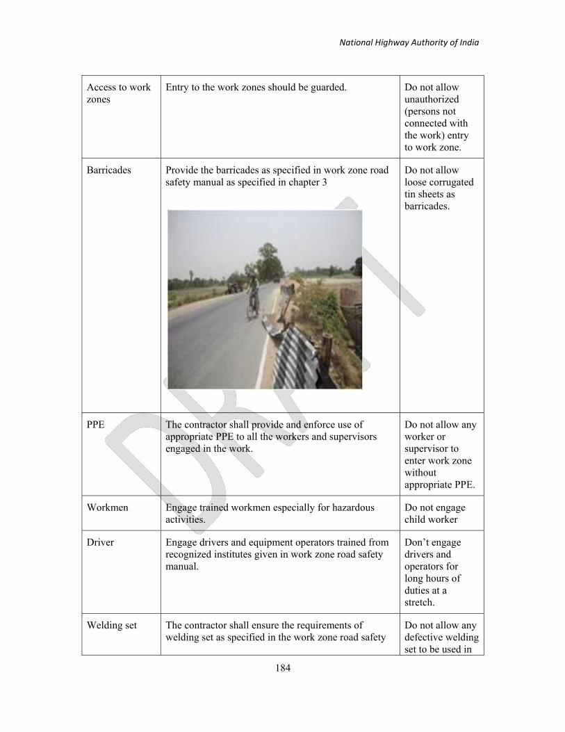
National Highway Authority of India
184
Access to work zones
Entry to the work zones should be guarded. Do not allow unauthorized (persons not connected with the work) entry to work zone.
Barricades Provide the barricades as specified in work zone road safety manual as specified in chapter 3
Do not allow loose corrugated tin sheets as barricades.
PPE The contractor shall provide and enforce use of appropriate PPE to all the workers and supervisors engaged in the work.
Do not allow any worker or supervisor to enter work zone without appropriate PPE.
Workmen Engage trained workmen especially for hazardous activities.
Do not engage child worker
Driver Engage drivers and equipment operators trained from recognized institutes given in work zone road safety manual.
Don’t engage drivers and operators for long hours of duties at a stretch.
Welding set The contractor shall ensure the requirements of welding set as specified in the work zone road safety
Do not allow any defective welding set to be used in

National Highway Authority of India
185
manual.__________
the work zone.
Gas cutting set The gas cutting devices shall be equipped with non return valve, flash back arrestor, and pressure gauges. The gas cylinders shall be transported in trolleys.
Do not allow domestic gas cylinders. Do not transport cylinders without putting them in trolleys.
Working/Access to heights
Workers engaged in work at heights shall be equipped with safety belts and barricades need to be provided if the work on the slabs
Do not allow workers to work at heights without safety belts and barricades

National Highway Authority of India
186

National Highway Authority of India
187
4.7 References:
DMRC (20XX) Conditions of Contract on Safety, Health, and Environment Phase II. Delhi Metro Rail Corporation, N. Delhi
MoRTH (2001) Specifications for Road and Bridge works, Indian Roads Congress
DoL (1984) Road works safety guide, Safety in Construction no. 25, Department of Labour, New Zealand, Accessed 14 Jan 2012
www.osh.govt.nz/order/catalogue/archive/roadworksafety.pdf,
FHWA (2010) Workers safety FHWA Work zone, Accessed 01 May 2011 http://www.ops.fhwa.dot.gov/wz/workersafety/index.htm
MFL Occupational Health Centre Inc. (2010) Road construction and Maintenance workers. http://www.mflohc.mb.ca/fact_sheets_folder/road%20construction.html Accessed 25 July 2011
NNRDA PMGSY Construction Guidelines http://www.pmgsy.nic.in Accessed 03 Oct 2011
SAFETY BRIEF (2010) Safe Motor Grade Operations, Connecticut Transportation Institute, University of Connecticut, USA
CMI (2002) Operators Manual, Slip form paver, CMI Terex Corporation, Oklahoma city, Oklahoma, USA

National Highway Authority of India
188
5. Temporary Structures Safety∗
5.1 Introduction
Unit 5 presents guidelines on formwork, scaffolds, and work at height, working platform, ladders, ramps etc. These are referred to as temporary structures and they are required for the construction of permanent structures. In the early part of this section, the terms pertaining to temporary structures are defined. The guidelines for the preparation of formwork scheme (plan) are presented. The suggested formwork arrangements for commonly used structural elements are provided. The unit also contains the checklist to be used by the contractor for implementing the formwork arrangement. It also contains the checklist to be used for auditing purposes. The unit ends with the description of penalties for non compliance of various provisions provided in this unit.
5.2 Definition of Temporary Structures Related Terms
The following definition of formwork related terms shall apply.
According to IS 6461 Part V, formwork (shuttering) is a complete system of temporary structure built to contain fresh concrete so as to form it to the required shape and dimensions and to support it until it hardens sufficiently to become self-supporting. It includes the surface in contact with the concrete and all necessary supporting structure.
The terms sheeting (sheathing), form (shutter), falsework, centering, mould, scaffold (scaffolding), and are commonly used in the context of formwork which must be clearly understood. The definition given in IS 6461 Part V is reproduced in the Table 1.
Sheeting (Sheathing)- That part of the form, which is in contact with the concrete.
Form (Shutter)- (a) That part of formwork, which consists of the sheeting and its immediate supporting or stiffening members. (b) A temporary structure or mould for the support of concrete while it is setting and gaining sufficient strength to be self-supporting.
Falsework- (a) Falsework is the temporary structure erected to support work in the process of construction. It is composed of shores, formwork for beams or slabs (or both) and lateral bracing. (b) That part of formwork, which supports the forms usually for a long structure, such as a bridge.
Centering (Centering)- It is a temporary supporting structure to a soffit. It is the specialized formwork used in the construction of arches, shells space structure where the entire falsework is struck or decentred as a unit to avoid introducing injurious stress in any part of structure.
∗ This unit is based on Jha, K.N, Formwork for concrete structures, in press, McGraw Hill
group of companies

National Highway Authority of India
189
Mould -A frame for casting, precast concrete units.
Scaffold (Scaffolding)- A temporary structure for gaining access to higher levels of the permanent structure during construction.
5.3 Guidelines for the preparation of Formwork Schemes (Plans)
The formwork plans should include the following information:
1. Design assumptions
2. Types of materials, sizes, lengths, and connection details
3. Sequence of removal of forms and shores
4. Anchors, form ties, shores, and braces
5. Field adjustment of the form during placing of concrete
6. Working scaffolds and gangways
7. Weepholes, vibrator holes, or access doors for inspection and placing of concrete
8. Construction joints, expansion joints
9. Sequence of concrete placements and minimum/maximum elapsed time between adjacent placements
10. Chamfer strips or grade strips for exposed corners and construction joints
11. Foundation details for falsework
12. Special provisions such as protection from flood water, ice, and debris at stream crossings
13. Form coatings and release agents
14. Means of obtaining specified concrete
15. Location of box outs, pipes, ducts, conduits and miscellaneous inserts in the concrete, attached to or penetrating the forms
16. Location of spacing of rubber pads where shutter vibrations are used.
5.3.1 Reporting of dangerous occurrences
The contractor shall ensure that all cases of collapse or subsidence of any other part of any structure, formwork, launching girder, working platform, staging, scaffolding, and all means of access shall be reported to the Inspector having jurisdiction, whether or not any disablement or death is caused to the worker.

National Highway Authority of India
190
5.3.2 Frequency of inspection
There should be a weekly inspection of scaffold by scaffolding supervisor and the record for the same should be maintained. The inspection of scaffold must be based on the checklist provided for scaffold in the Road Traffic and Work Zone Safety Manual.
Contractors’ Site SHE Manager will ensure that a system of routine inspections is carried out periodically to all temporary structures that will pose a hazard to workmen.
Specific inspections (without a predetermined date and as and when needed) shall be performed for formwork before concreting by formwork erector. Competent supervisors shall usually perform such inspections in accordance with the check list specified in the manual. The check list is indicative only and depending on the method statement submitted or developed procedures, the Indian standards, rules and regulations, and Employer’s requirements, the same shall be modified. The contractor shall preserve the records for such inspection for audit.
5.4 Formwork Arrangement for Typical Structural Elements
In the following sections some suggested formwork arrangement for commonly used RCC elements are provided. A number of manufacturers are available in the country who provide similar arrangements. NHAI would prepare a list of approved manufactures and include the list in the specification on formwork.
5.4.1 Wall formwork
Wall formwork should be so designed to take the pressure exerted by the concrete on formwork besides other anticipated loads. The formwork components should be designed according to relevant Indian Standards and the manufacturer’s guidelines. Suitable provision for working platform shall be provided (
Figure 5-1 ). Application of travelling and climbing formwork shall be encouraged in case wall is to be cast in more than 2-3 lifts.

National Highway Authority of India
191
Figure 5-1 : Typical wall formwork
(Photograph courtesy- Formwork for concrete structures, in press Tata Mc Graw Hill)

National Highway Authority of India
192
5.4.2 Column Formwork
Wall formwork should be so designed to take the pressure exerted by the concrete on formwork besides other anticipated loads. The formwork components should be designed according to relevant Indian Standards and the manufacturer’s guidelines. Suitable provision for working platform shall be provided (see Figure 5-2 a) Suitable arrangement for reaching the working platform shall also be provided. Two such arrangements are shown in Figure 5-2 (a) and (b).
Figure 5-2 (a) Column form work (b) Column form work showing access arrangements
((Photograph courtesy- Formwork for concrete structures, in press Tata Mc Graw Hill))

National Highway Authority of India
193
5.4.3 Well/Caisson formwork
For the purpose of this manual, the well/caisson formwork is supposed to consist of three distinct components: cutting edge, kerb, and wall. The cutting edge shall be manufactured in steel form which can assist the caisson in going down. The forms should be made in such a manner that they are able to be removed or replaced with ease and in safe manner. The annulus on which the cutting edge is to be placed shall be levelled and compacted uniformly, so as to avoid the settlement during kerb concreting. The wall formwork can be of timber or steel. It shall have the arrangement for working platform throughout the perimeter of the wall and shall also have a safe access arrangement from the ground.
5.4.4 Pier and Pier Cap Formwork
Pier formwork is similar to wall formwork. The contractor shall see that the pier formwork is sturdy and safe to withstand all the loads exerted to it. The pier formwork can be either supported on the ground or can be supported on the previously cast concrete. In both the cases the method statement for construction shall be prepared by the contractor which shall be approved by the contractor if found appropriate. The CSC shall ensure that all necessary arrangements for access, working platform, and handrails are provided in the formwork arrangement. One such possible arrangement for guidance is given in Figure 5-3.
(a) Formwork arrangement of Pier for first lift (b) Formwork arrangement for subsequent lifts
Figure 5-3 Formwork arrangement of pier for first lift and subsequent lifts
((Photograph courtesy- Formwork for concrete structures, in press Tata Mc Graw Hill)

National Highway Authority of India
194
One typical formwork arrangement for Pier cap casting is shown in Figure 5-4. The
formwork for Pier Cap is supported on the previously cast concrete. The arrangement for
access, working platforms and handrails should be shown in the formwork scheme (see
Figure 5-4 ).
Figure 5-4 Sectional view of formwork for pier cap
((Photograph courtesy- Formwork for concrete structures, in press Tata Mc Graw Hill)
5.4.5 Girder and Deck Slab Formwork
Precast or cast in situ Girder can be adopted depending on the method statement. In both the cases however, suitable arrangement shall be provided to restrain the Girders from falling due to the application of accidental horizontal loads. In the absence of such restraints, a number of accidents have occurred in past. The arrangement for restraining the girder till the time diaphragm walls are cast shall be prepared by the contractor. This shall be checked and approved if found suitable by the CSC. One such typical arrangement of restraining is shown in
Figure 5-5 and Figure 5-6, which can be used only for guidance. In any case, the actual arrangement shall be designed on case to case basis by the contractor.

National Highway Authority of India
195
Figure 5-5 Plan (Temporary arrangement for Girder restraining)
Figure 5-6 Section BB (Temporary arrangement for Girder restraining)

National Highway Authority of India
196
In most of the cases the girders are prestressed. The method statement for casting and prestressing girders are given below only for guidance.
(a) The method statement for such works should be such that the time period between
the placement/construction of individual girder on bearings and the construction
of deck slab should be minimized. This involves preferring precast construction of
girders over the cast in situ type girders together with first stage prestressing that
allows immediate casting of cross girders (diaphragm wall) and the deck slab
before final prestressing is done.
(b) The use of seismic arrestors on the pier cap should be preferred irrespective of the
seismic zone in which the construction falls. The use of seismic arrestors will
provide some additional safety measure and would prevent such failure.
The suggested sequence of construction is given below:
Step 1: Cast girder no. 1
Step 2 : After 7 days, remove side shutter and bottom shutter around the bearing area only.
Step 3: Erect support system and lock with bearing pedestal using wooden wedges/packings.
Step 4: Lock girder with packing between support system and girder.
Step 5: Tighten stirrup head on both sides together. Stirrup heads are nominally tightened
only to ensure that the stirrup heads are in proper contact with diaphragm soffit.
Step 6: Prestress the girder to stage 1 and stage 2 and grout the cable as per specifications.
Step 7: Cast girder no. 2. Repeat steps 2 to 6.
Step 8: Weld top two reinforcement bars and bottom two reinforcement bars of the two
girders immediately after the girder is cast.

National Highway Authority of India
197
Step 9: Similarly complete girders no. 3 and 4. All the four girders shall be inter connected by
welding diaphragm reinforcement.
Step 10: Erect diaphragm staging and shuttering as per approved drawing.
Step 11: Concrete deck slab and diaphragm
Step 12: Remove the supporting system after the specified days of deck concreting.
Deck slab formwork can be supported on tubular scaffold or cribs. They may be also
supported on the girders. In all these cases the contractor shall prepare the method statement
and scheme drawings. This shall be approved by the CSC if found appropriate. The
contractor shall make sure that the tubular scaffolds and cribs are supported on a firm ground.
The scaffolding should be resting on sleepers or pedestal as suggested in the scheme. The
scaffolds should be provided with foot plate as per the scheme. The support arrangement of
cribs must be carefully looked into and should comply with the scheme drawing. All
necessary arrangements shall be taken by the contractor to ensure that there is no scouring
underneath the sleeper/pedestal on which the the leg of scaffold/cribs rest. The scheme
drawings must show the access arrangement and should have the provision of walkway
platform, handrails, and provision to tie the safety belts.
5.4.6 Formwork for Edge beam/Parapet
An arrangement similar to the one shown in Figure 5-7 may be adopted for casting the edge beams for flyovers and bridges.

National Highway Authority of India
198
Figure 5-7: Edge beam formwork
((Photograph courtesy- Formwork for concrete structures, in press Tata Mc Graw Hill))
5.5 Work at height
The contractor shall plan and supervise all work carried at height (both above and below ground) so that they are executed in a safe manner. The contractor shall arrange appropriate work equipment consisting of guard rail, toe board, working platform, safety net, personal fall protection system, ladders whenever work at height is carried out. It is the responsibility of the contractor to ensure that only competent persons are employed. The contractor shall ensure suitable and sufficient steps to prevent fall of any material from heights and thereby avoid injury thereof. The contractor shall erect a board indicating ‘work at height’ to warn people from going underneath the area.
National Highway Authority of India
199
5.5.1 Inspection of places of work at height
The contractor shall ensure that all work equipments are in usable condition and they are checked on each occasion before they are put to use. The contractor shall put a procedure in place through which any defect observed at any time is brought to the notice of the concerned supervisor and rectified immediately.
5.5.2 Duties of persons at work
The contractor shall devise a procedure in which any workmen employed by the contractor shall report to the supervisor about any defect relating to work at height which is likely to endanger the safety of any person. The contractor shall ensure that every workman shall use any work equipment or safety device provided to him for work at height by the contractor, in accordance with the instruction and the training if any received by him.
5.5.3 Requirements for existing places of work and means of access or egress at height
The contractor shall ensure that every means of access or egress at height shall be stable and of sufficient strength and rigidity for the purpose for which it is intended to be or is being used. They should rest on a stable, sufficiently strong surface and be of sufficient dimensions to permit the safe passage of persons and the safe use of any plant or materials required to be used and to provide a safe working area having regard to the work to be carried out there. They should not have any gap through which either a person, or any material may fall. They should be constructed in such a way to prevent the risk of slipping or tripping.
5.5.4 Requirements for guardrails, toe-boards, barriers and similar collective means of protection
The contractor shall ensure that all means of protection such as guard-rails, toe-boards, and barriers etc. shall be secured and shall have sufficient dimensions, sufficient strength and rigidity for the purposes for which they are being used. These protection means shall be so placed that they prevent the fall of any person, or of any material or object. The top guard-rail or other similar means of protection shall be at least 950 millimetres above the edge from which any person is liable to fall and any intermediate guardrail or similar means of protection shall be positioned so that any gap between it and other means of protection does not exceed 470 millimetres.
5.6 Working Platforms
In this section the requirements for all working platform are specified.

National Highway Authority of India
200
5.6.1 Requirements for all Working Platforms
The contractor shall ensure that all working platform in use shall be of sufficient strength and rigidity. The working platform should be so erected and used that its components do not become accidentally displaced so as to endanger any person. Also, the platforms should be able to be dismantled easily in such a manner that no accidental displacements take place.
A working platform shall be of sufficient dimensions to permit the safe passage of persons and the safe use of any plant or materials required to be used and to provide a safe working area. It should possess a suitable surface and, in particular, be so constructed that the surface of the working platform has no gap through which a person or any material could fall and injure a person. The working platform should be such that it can be erected easily without the risk of slipping or tripping. While loading a working platform and any supporting structure, the contractor shall ensure that it does not give rise to a risk of collapse or to any deformation, which could affect its safe use.
The contractor shall ensure that the supporting structure for holding each working platform shall have stability, rigidity, strength, and suitable composition. In case the supporting structure is a wheeled structure, it should be prevented by appropriate devices from moving inadvertently, and slipping by some secure attachment.
5.7 Scaffolding
5.7.1 Safety Provisions in Building the Scaffolds
i) Every scaffold should be braced by means of longitudinal and transverse bracing systems so as to form a rigid and stable structure. So also every scaffold should be effectively tied to a building to prevent movement of scaffold either away or towards the building.
ii) Where heavy wind or gale force are expected, it would be necessary to take special precaution and install additional ties to the scaffold to prevent overturning and collapse.
iii) Guide rails and toe boards must be provided for all working platforms to ensure safety for workmen.
iv) All working platforms should be fully covered to prevent materials falling and causing injury to the workers or passersby.
v) Safety nets or other screens should be provided to catch any falling materials.
vi) The use of barrels, boxes, loose earth pads or other unsuitable objects as supports for uprights and working platform, should not be permitted.

National Highway Authority of India
201
vii) Care should be taken to see that no uninsulated wire exists within 3 m of the working platforms, gang ways, runs etc. of the scaffolds.
viii) Scaffolds on thoroughfares should be provided with warning light, if general light is not sufficient to make it clearly visible.
ix) Men should not be allowed on scaffolds during storms or high winds.
x) Grease, mud, paint, gravel or plaster or any such material shall be removed from scaffold platforms immediately.
xi) Either sand or saw dust or other suitable material shall be spread on platforms to prevent slipping.
xii) All projecting nails from platforms or other members shall be removed.
xiii) During dismantling or scaffolds necessary precautions shall be taken to prevent injury to persons due to fall of loose materials. The bracing and other members of the scaffolds shall not be removed prematurely while dismantling the entire scaffolds so as to avoid danger of collapse.
xiv) When scaffolds are to be used to a great extent and for long period of time, they should be inspected from time to time to ensure its soundness.
xv) Boards and planks used for platforms, gangways should be of sound quality and proper thickness closely laid and securely fastened and placed.
5.7.2 Additional requirements for scaffolding
The contractor shall draw up an assembly, use, and dismantling plan of scaffold system depending on the complexity of the scaffolding selected by a competent person. This may be in the form of a standard plan, supplemented by items relating to specific details of the scaffolding in question.
The contractor shall keep a copy of the plan for the use of persons concerned in the assembly, use, dismantling or alteration of scaffolding until it has been dismantled including any instructions it may contain.
Strength and stability calculations for scaffolding shall be carried out unless it is assembled in conformity with a generally recognised standard configuration.
The contractor shall ensure that Scaffoldings are assembled, dismantled or significantly altered only under the supervision of a competent person and by persons who have received appropriate and specific training.
The contractor should scaffold tag such as ‘scaffold good for use’, ‘scaffold not in use’, and ‘scaffold under dismantling’ etc. The scaffolds shall be of appropriate dimensions, strength, form and layout suitable for the purpose for which they are being erected.

National Highway Authority of India
202
5.8 Ladders
The contractor shall ensure that a ladder is used for work at height only if a risk assessment has demonstrated that the use of more suitable work equipment is not justified because of the low risk, the short duration of use, and the unalterable existing features at sites. The contractor shall use only metal ladders and under no circumstances shall use Bamboo ladders. The surface upon which a ladder rests shall be stable, firm, of sufficient strength and of suitable composition safely to support the ladder so that its rungs or steps remain horizontal, and any loading intended to be placed on it.
The stability of a ladder during use shall be ensured. A ladder used for access shall be long enough to protrude sufficiently above the place of landing to which it provides access, unless other measures have been taken to ensure a firm handhold. No interlocking or extension ladder shall be used unless its sections are prevented from moving relative to each other while in use. A portable ladder shall be prevented from slipping during use by proper securing and use of effective anti-slip device and shall be prevented from moving before it is stepped on.
5.9 Launching Operation
The contractor shall take all precaution at all stages of the launching operation. The contractor shall prepare a comprehensive Method Statement for the launching operation, adhering to the safe practices. Particular reference shall be made to the provisions on working at height. The safety of workers and the girder is paramount importance in the launching operation as the entire process of launching is undertaken at an elevated level. The following general guidelines shall be adhered throughout the launching operation.
The contractor shall arrange for necessary ‘working platforms’ and fall protection anchorage arrangement in the launching girder itself. The launching girder should preferably have provisions for light fittings. The casting yard shall be established ensuring the provision given in the next section. The contractor shall provide necessary PPEs All workmen engaged in the launching operation fabrication of reinforcement, concreting the segment shall be provided with. The contractor shall ensure that all launching operations are carried out under the direct supervision of the responsible engineer of the contractor and at no point of time the launching operations remain unsupervised.
5.10 Batching Plant / Casting Yard
The contractor shall plan the layout of batching plant / casting yard in a manner that it results in a smooth flow of all the operations involved with pre-casting. It is preferable to barricade the batching plant / casting yard area and make it a compulsory PPE zone. Access roads and internal circulation roads shall be well laid and maintained properly at all time. The entire area should have proper drainage and lighting system. Waste water resulting from the various

National Highway Authority of India
203
operations involved with pre-casting shall be disposed off only after proper treatment. Time office, canteen, drinking water, toilet and rest place shall be suitably located for the easy access to workers. All the facilities shall be properly cleaned and maintained during the entire period of operation. Manual handling of cement shall be avoided to a larger extent. Whenever it is absolutely necessary the workmen shall be given full body protection, hand protection and respiratory protection as a basic measure of ensuring better health. The contractor shall ensure the appropriate PPEs to all workmen.
5.11 Work over water
The contractor shall ensure that all construction personnel wear minimum requirements of PPE mentioned elsewhere in the manual. The contractor shall display the warning Signs of Deep water at appropriate locations. The contractor shall ensure edge protection including guard rails and toe boards etc. The contractor shall ensure suitable rescue equipment and provide training on how to use them.
5.11.1 Rescue Equipment
The contractor shall arrange Lifebuoys with rescue lines provided at intervals along the site and positioned conveniently for use in an emergency. Floating grab lines should be attached at intervals or floating plant. All personnel must wear life jackets, or buoyancy aid equipped with a whistle and lights (during darkness). The contractor shall arrange inspection of all rescue equipments by a competent person to ensure it is present and in good condition. The contractor shall provide enough trained personnel for the use of rescue equipment and emergency procedures.
5.11.2 Rescue Boats
On fast flowing rivers, a power-driven boat should be provided and properly equipped, including lifebuoy with buoyant rope (or) rowing boat. The rescue boats should preferably be fitted with swivelling searchlights.
5.11.3 Standby Person
The contractor shall arrange competent boatmen and trained first aid person on a continuous basis while working over water. These persons should not be used for any other purpose. The platforms and ladders shall be kept clean and clear of debris and tripping hazards. The contractor shall use safety nets to arrest falls where standard working platforms or harnesses cannot be provided.

National Highway Authority of India
204
5.12 Checklists (Do’s and Don’ts)
Structural Safety
Sl. No. Do’s Don’ts
Shores The contractor shall use standard
built up frames manufactured by
reputed manufacturers and as per the
latest edition of Indian Standards on
Scaffolding frames.
Don’t use make shift built up frames.
Formwork
design
Formwork design should show the access
arrangements including provision of ramp,
walkway, access and approach at the work
locations. These must be well designed,
particularly with respect to slopes of ramps,
inclination of steps, provision of handholds,
removal of obstacles, and proper lighting.
Do not proceed with the work unless
the formwork design and drawings are
approved by the consultant or
independent agency as per the
requirement.
Checking of
Formwork
design and
drawings
The formwork design and drawings must be
independently checked by third party. A
certificate to this effect must be available for
inspection by the CSC and a copy sent to
Employer.
No loading of formwork should be
allowed until Independent Check has
been undertaken and certification
made that the formwork is constructed
as designed and/or is now safe to load.
Checklist of
formwork
For implementation, the checklist based on
the formwork design and drawing must be
cross checked by the supervision consultant.
The checklist must be part of Request for
Inspection (RFI).

National Highway Authority of India
205
Access
arrangement
Ladders/stairways/ramps are adequately
secured and they are made with standard
components.
Do not use shuttering plates to form
access arrangement.

National Highway Authority of India
206
Ladders/stairways/ramps are adequately
secured and they are made with standard
components.
Do not use iron grids to form access
arrangement.
Do not provide any gap in between the
access path.
Do not use ladder made up of ballies.

National Highway Authority of India
207
Do not place ladder on the edge of
deep excavation
Do not rest ladder on pipes which in turn are supported on reinforcement
inserted into weepholes of the concrete wall
Bracings
Design the horizontal and diagonal bracings
properly. Install these bracings exactly as
per design.
Do not use reinforcement bars as
horizontal and diagonal bracings.

National Highway Authority of India
208
Working
platform
The working platform should be designed
and be part of the temporary structures
drawings. It should specify its maximum
load carrying capacity.
Do not use shutter plates to form
support for working platform.
PPE Provide sufficient and appropriate personal
protective equipment such as hard hat
(helmet), safety shoes, safety belts, hand
gloves, goggles, ear plugs etc. to the workers
and supervisors depending on the
requirement.
Do not allow workmen and supervisor
to work without appropriate PPE.
5.13 Penalties for Non Compliance
In view of the commitment of NHAI towards work zone safety, it is reiterated here that any
lapse on part of contractor/CSC will be viewed very seriously. For the first lapse of non-life
threatening violations warning to the concerned agencies shall be issued by the project
director and for the first repeat of such non-compliances the 2% amount of the contractor
from its running bill would be withheld as per the provision of relevant clause of COPA.
Subsequent repeat of such non-life threatening lapses would attract a penalty as provided in
Table 5-1. For life threatening lapses by the contractor the very first instance of such lapse
would attract the penalty as given in Table 5-1.

National Highway Authority of India
209
Table 5-1 Penalty for non-compliance of provisions in structural safety SL. NO
Subject head Description of the non compliance Penalty
1. Working at Height / Ladders and Scaffolds
i) Not using or anchoring Safety Belt ii) Not using Safety Net iii) Absence of life line or anchorage point to anchor safety belt iv) Non-compliance of v) Using Bamboo ladders vi) Improper usage (less than 1m extension above landing point, not maintaining proper slope) vii) Aluminium ladders without base rubber bush viii) Usage of broken / week ladders ix) Usage of re-bar welded ladders x) Improper guardrail, toe board, barriers and other means of collective protection) xi) Improper working platform xii) Working at unprotected fragile surface xiii) Working at unprotected edges
Rs.10,000 per single violation Compounded to a maximum of Rs.1,00,000 at any single instance
2. Launching operation Non-adherence of any of the
provisions mentioned in ‘launching operation’ clause
Rs. 50,000 for first violation and Rs.1,00,000 for subsequent violations .

National Highway Authority of India
210
6. Worker and Work Zone Safety ∗
Highway construction zones are always hazardous environment. At highway construction zones, there are numerous works that is to be done manually including clearing and preparing highway work zones, installing traffic barricades, cones, and markers; and controlling traffic passing near, in, and around work zones, install sewer, water, and storm drain pipes, and place concrete and asphalt on roads. Other highly specialized tasks include operating laser guidance equipment to place pipes; operating air, electric, and pneumatic drills; and transporting and setting explosives for tunnel, shaft, and road construction. So the workers are at high risks of fatal injury and serious nonfatal injury, and each year reported more than hundreds of workers killed and thousands of injured while working in and around the work zone.
Therefore, the safety of ‘workers and work-zone’ is not just a matter of concerns the workers as individual; it is not a question of their following rules of good and healthy living. Their protection is a social question: it concerns the conditions in which they are offered employment and are exposed to work. It is an issue that must be seen within the context of the relations between employers and their employees, and of the legal framework that structures these relations. Ultimately, it is up to workers themselves, acting collectively through their unions, to ensure that their health and safety is protected.
Construction contractors, contracting agencies, and others responsible for work zone safety face the challenge of providing a safe workplace while ensuring the safe movement of the public through the work zone. Highway and street construction presents a complex work situation in which workers face multiple injury risks under conditions that may change without warning.
The part “Worker and Work Zone Safety” of the manual provides some of the guidance’s for developing a framework in the context of safety for the contractors as well as for the workers for minimizing the risks in the highway construction zones.
∗ This unit is based on DMRC, Conditions of Contract on Safety, Health, and Environment Phase II. Delhi Metro Rail Corporation, N. Delhi

National Highway Authority of India
211
6.1 Material Handling
6.1.1 Hazardous materials handling, storage, and use
I. General responsibility of the Contractor during construction activity
The Contractor has to maintain evidence to show he has performed the following tasks:
a) Identification of major accident hazards in construction activities
b) Taken adequate steps to prevent major accidents and to limit their consequences
c) Provide workers with information, training, and equipment, including antidotes
d) Notification of major accidents
e) Undertake full analysis and send information to Labour Directorate and the concerned Ministry
f) Not to undertake any construction activity without submitting safety report to the authority 3 months before commencing activity
g) Furnishing a further report if the Contractor makes any change in construction activity.
h) Preparation of an up-date on-site emergency plan to deal with major accidents with names of responsible persons and those authorised to take action
i) Every worker to be informed of emergency plan.
j) Maintaining information about persons outside the worksite and the nature of accident hazard to which they are exposed and the safety measures to be adopted
k) Maintenance of Safety Data Sheet of all the materials that are being used in the construction activities and providing this information to the workers
l) Container of hazardous chemicals to be clearly labelled about contents, manufacturer, and physical, chemical and toxicological data
m) Provision of adequate steps to contain contaminants and prevent accidents; and provide workers with safety information, training and equipment
n) Proper labelling of all hazardous materials
o) Packaging, labelling, and transport shall be done in accordance with Motor Vehicles Act, 1988
p) Reporting of polluting accidents to the State Pollution Control Board
National Highway Authority of India
212
6.1.2 Manual material handling
I. General: Construction workers are at a higher risk than most workers in receiving a
manual handling injury. Manual handling involves any activity requiring the use of
force exerted by a person to lift, lower, push, pull, carry or otherwise move, hold or
restrain a person, animal or thing. Workers may suffer from musculoskeletal problems
such as aches, strains and sprains as a result of manual handling. These can also be
caused by other tasks which involve repetitive movements, force, unusual postures,
prolonged pressure on a joint, badly organised working practices or work
environment. Effects on health can include:
Sprains or Strains
Backache
Sciatica
Hernias
Arthritis
Swelling of the wrist, forearm, elbow and shoulder
II. Safety Precautions that are to be maintained by the Contractor are:
a. Designing and organising tasks to avoid manual handling completely, or at
least restrict it
b. Using automation and lifting equipment
c. Organising manual handling tasks in a safe way, with loads split into smaller
ones, and proper and regular rest periods provided
d. Information and training to workers for each task, and the use of equipment
and correct handling techniques
6.1.3 Mechanical material handling
I. General: Construction equipment may include dumpers and dump trucks, lift
trucks and telescopic handlers, piling rigs, vibro hammers, rail welding
equipment, mobile elevating work platforms, cranes, tipper lorries, lorry loaders,
skip wagons, 360° excavators, 180° backhoe loaders, crawler tractors, scrapers,
graders, loading shovels, trenchers, side booms, pavers, planers, chippers, road
rollers, locomotives, tankers and bowsers, trailers, hydraulic and mechanical
breakers etc.

National Highway Authority of India
213
II. General precautions for Mechanical material handling:
a. The Contractor shall ensure that all construction equipment is in sound
mechanical working condition and certified by either a competent person
under Factories Act, or manufacturers’ warranty in case of brand new
equipments or authorised persons / firms approved by the Employer before
induction at any site
b. Every such certificate shall have the date of purchase, main overhauling
undertaken in the past, any accident to the equipment, visual examination
details, critical components, checklist of safety devices and its working
condition, manufacturer’s maintenance checklist, past projects wherein the
equipments were used etc as its minimum content
c. All vehicles shall be fitted by the Contractor with audible reverse alarms and
maintained in good working condition. Reversing shall be done only when
there is adequate rear view visibility or under the directions of a banksman
III. General operating instructions that shall be maintained by the Contractor at
any construction site are:
A. Drivers entering site shall be instructed to follow the safe system of work
adopted on site. These shall be verbal instructions or, preferably, written
instructions showing the relevant site rules, the site layout, delivery areas,
speed limits, etc
B. No passengers shall be carried, unless specific seating has been provided
in accordance with the manufacturer’s recommendations
C. Working on gradients beyond any equipments capability shall not be
allowed
D. Prevention of dumper and dump truck accidents should be managed by
providing wheel stops at a sufficient distance from the edges of
excavations, spoil heaps, pits, etc
E. The manufacturer’s recommended bucket size must not be exceeded in
excavators
F. If excavators are operating on a gradient which cannot be avoided, it must
be ensured that the working cycle is slowed down, that the bucket is not
extended too far in the downhill direction, and that travel is undertaken

National Highway Authority of India
214
with extreme caution. A large excavator must never be permitted to travel
in a confined area, or around people, without a banksman to guide the
driver, who should have the excavator attachment close in to the machine,
with the bucket just clear of the ground. On wheeled excavators, it is
essential that the tyres are in good condition and correctly inflated. If
stabilizing devices are fitted, they should be employed when the machine
is excavating
G. When the front shovel of the 1800 backhoe loaders is being employed, the
backhoe attachment shall be in its “travel” position, with the safety locking
device in place
H. When operating the backhoe in poor ground conditions, the stabilisers tend
to sink into the surface of the ground, reducing stability. Therefore
frequent checks shall be made for the stability of the machine. The loading
shovel should always be lowered to the ground to stabilise the machine
when the backhoe is employed
I. The netting operation of the skip wagons should be carried out prior to
lifting the skip to reduce the risks of working on the rear platform
J. If a tractor dozer is employed on clearing scrub or felling trees, it shall be
provided with adequate driver protection
K. When two or more scrapers are working on the same job, a minimum
distance of at least 25m shall be kept between them
L. In case of hydraulic breakers, hydraulic rams and hoses shall be in good
working condition
M. All wood working machines shall be fitted with suitable guards and
devices such as top guard, riving knife, push stick, guards for drive belts
and chains, and emergency stop switch easily accessible by the operator
N. Every moving and dangerous part to be securely fenced, and regularly
examined to prevent contact with the worker

National Highway Authority of India
215
Do Don’t
Movin
g parts
Moving part securely fenced Moving part is open.
O. Examination/operation of machinery to be done only by trained/certified
adult worker wearing tight fitting clothing
P. Provision of suitable devices shall be available for cutting off power in
emergencies from running machinery
Q. All parts such as lifting machines, chains, ropes and lifting tackle shall be
properly maintained and examined every 12 months
R. The lifting machines, chains, ropes and lifting tackle shall not be loaded
beyond marked safe working load
S. Crane should not approach within 6 m of the working place
T. Safe working speeds of revolving machinery should not be exceeded
U. Floors, stairs and means of access shall be of sound construction, properly
maintained, free of obstructions, and provided with handrails
V. Fencing should be provided for working at heights
W. Pits, sumps, openings in floors, etc shall be securely covered / fenced
X. Provision of escape, fire extinguisher and adequate training to the workers
in case of fire
Y. Safety Officers to be appointed where more than 1000 workers are
employed
Z. Compulsory disclosure of information regarding dangers, detailed health
and safety policy, and emergency plan to the workers

National Highway Authority of India
216
6.1.4 Handling of petroleum products
I. General provisions that are to be maintained by the Contractor at every
construction site are:
A. No person shall deliver or dispatch any petroleum other than the holder of
a storage license
B. The petroleum delivered or dispatched shall be of the class, and shall not
exceed the quantity, which the person to whom it is delivered or
dispatched is authorised to store with or without a license under the “The
Petroleum Rules, 1976”
C. Notwithstanding any other rule, petroleum Class B not exceeding 15,000
litres in quantity and packed in sealed air tight approved containers, may
be dispatched to a person not holding a storage license
D. Precautions shall be taken at all times to prevent escape of petroleum into
drain, sewer, harbour, river or watercourse or over any public road or
railway line
E. No child under the age of eighteen years and no person who is in a state of
intoxication shall be employed on the loading, unloading, or transport of
petroleum or in any premises licensed under these rules
F. Unless expressly provided in these rules, no person shall smoke and no
matches, fires, lights or articles or substances capable of causing ignition
of petroleum shall be allowed at any time in proximity to a place where
petroleum is refined, stored or handled or in a vehicle, carriage or vessel in
which petroleum is transported
II. Some Special precautions against accident that shall be maintained by the
Contractor are:
A. No person shall commit or attempt to commit any act which may tend to
cause a fire or explosion in or about any place where petroleum is refined,
stored or handled or any vehicle, carriage or vessel in which petroleum is
transported.
B. Every person storing petroleum and every person in charge of or engaged
in the storage, handling or transport of petroleum shall at all times:

National Highway Authority of India
217
Comply with the provisions of these rules and the conditions of any
license relating thereto;
Observe all precautions for prevention of accident by fire or
explosion; and
Prevent any person from committing any act referred to in the
earlier rule
6.1.5 Spill control management:
There are numerous chemicals like asphalt, coal tar, gasoline, diesel which are being used for
construction purpose and spill control management is one of the prime concerns for the safety
of workers.
I. The procedure and guidelines that the Contractor shall follow for spill
management process are:
a. Identification of potential chemical spill hazard
b. Risk assessment of spill via:
i. The nature of the spilled chemical (high/low hazards)
ii. The quantity of the spill (large or small)
iii. Location of the spill
II. The Contractor shall ensure that measures to control or eliminate the potential risk
follow the principles of:
a. Elimination: complete removal of risk of exposure
b. Replacement the substance with a less hazardous one
c. Isolation through distance or enclosure
d. Adoption of new engineering methods for redesigning the work area and
proper maintenance
e. Administrative – standard operating procedure, supervision, training,
rotation and signage
f. Provision of Personal Protective Equipment – protective clothing, safety
shoes, goggles, safety glasses and gloves etc.
III. Preparation for chemical spill shall be done through:
a. Safety Data Sheet including the special requirements for spill control such
as the type of fire extinguisher required, incompatible substances, and
reactivity with substances such as water or air

National Highway Authority of India
218
b. Spill kits should be available for use where assessed as required
IV. Requirements for spill facility to be monitored by the Contractor are:
a. Permanently installed secure roll-over bunds
b. Adequate supply of emergency drain covers
c. Necessary chemical spill station
d. Proper chemical storage areas
e. All areas where chemicals are stored shall have access to a spill kit (in
close proximity of the storage area)
f. Chemical storage cabinets
g. Provision of trays that are compatible with the contents
h. Chemical waste storage areas
i. Adequate supply of emergency drain covers
j. Adequate ventilation
k. Laboratory spill kit
l. Training and awareness
V. Cleaning up a chemical spill can be done through immediate actions of:
a. Clear the affected area.
b. Check for any persons involved
c. Personnel contaminated with chemicals must be decontaminated via
emergency shower and taken for medical examination
d. First aid facility at the site
e. Isolate the spill (if safe to do so)
f. Contact the laboratory technician for lowering risk of spills
g. Gather any information possible, i.e. identify the material and quantity,
gather relevant MSDS and assess any immediate risks
6.2 House Keeping
a. General: Many injuries result from poor housekeeping, improper storage of
materials, and cluttered work areas. To maintain a clean, hazard-free workplace, all
groups of management, supervisors, and workers must cooperate.
b. General provisions that can maintain adequate housekeeping and must be ensured by
the Contractor at the construction site as well as in the campsites are:

National Highway Authority of India
219
I. Daily removal of dirt and refuse
II. Keep tools in boxes, racks, or trays when not in use
III. Do not let materials such as scrap lumber, metal, and debris accumulate
which might cause a tripping hazard
IV. Weekly washing of floor. Keep aisle clear for safe passage of people and
material
V. Nails, pieces of wood with protruding nails, and other sharp objects should
not be left on floors and walkways; store them where they cannot be
stepped on
VI. Effective drainage of floor
VII. Regular painting of walls, partitions, ceilings
VIII. Keep exits clear; keep fire extinguishers readily accessible and free of
obstruction
IX. Store flammable and combustible materials in proper containers and in
flammable liquid storage cabinets
X. Effective arrangement for treatment of wastes and effluents to render them
innocuous and for their eventual disposal
6.3 Noise
a. General: Noise may be defined as unwanted sound. Noise is perhaps the most
widespread hazard in any construction environment and it is well known that
workplace noise can cause deafness and associated conditions such as tinnitus
(ringing in the ears). Despite this, workers are exposed to noise levels which can
cause permanent noise-induced hearing loss. For example, noise from:
Trucks
Machinery
Tools in a workshop
Batching plant and HMP site
Stone crusher unit
Compressor and Generators
Hearing protection is very necessary for construction workers who are directly
exposed to a high level noise for more than the permissible limit (more than 90

National Highway Authority of India
220
decibels for 8 hours), and where the noise cannot be reduced or isolated from the
worker.
b. Control Requirement: Contractor has to ensure that construction material is operated
and transported in such a manner as not to create unnecessary noise as outlined below:
I. Perform work within the procedures outlined herein and comply with
applicable codes, regulations, and standards established by the Central and
State Government and their agencies.
II. Keep noise to the lowest reasonably practicable level. Appropriate
measures will be taken to ensure that construction works will not cause
any unnecessary or excessive noise, which may disturb the occupants of
any nearby dwellings, schools, hospitals, or premises with similar
sensitivity to noise. Use equipment with effective noise-suppression
devices and employ other noise control measures so as to protect the
public.
III. Schedule and conduct operations in a manner that will minimise, to the
greatest extent feasible, the disturbance to the public in areas adjacent to
the construction activities and to occupants of buildings in the vicinity of
the construction activities.
IV. The Contractor shall submit to the Employer a Noise Monitoring and
Control Plan (NMCP) under contract specific Site Environmental Plan. It
shall include full and comprehensive details of all powered mechanical
equipment, which the Contractor proposes to use during daytime and night
time and of the proposed working methods and noise level reduction
measures. The NMCP shall include detailed noise calculations and
vibration levels to demonstrate the anticipated noise generation and
vibrations by the Contractor.
V. The NMCP prepared by the Contractor shall guide the implementation of
construction activity. The NMCP will be reviewed on a regular basis and
updated as necessary to assure that current construction activities are
addressed. It may appear as a regular agenda item in project coordination
meetings, if noise is an issue at any location in the contract.

National Highway Authority of India
221
c. Elimination or control of exposure to the noise at workplace:
I. Protection against the effects of occupational noise exposure should be
provided when the sound level exceeds the threshold values as specified by
“The Control of Noise at Work Regulations 2005”.
II. Contractor shall ensure about elimination of risks from noise at source.
III. Provision of personal hearing protectors, which are appropriate to the
activity, shall be undertaken only when all other possible noise abatement
methods have been undertaken.
IV. Actions that shall be based on the prevention are:
A. Other working methods which reduce exposure to noise
B. Appropriate work equipment emitting the least possible noise
C. Proper design and layout of workplaces, work station and rest
facilities
D. Reduction of noise by technical means
E. Maintenance programmes for work equipment, the workplace and
workplace system
F. Limitation of the duration and intensity of exposure to noise
G. Appropriate work schedule with adequate rest periods
H. Ensure that employees are not exposed to noise above the exposure
limit
I. If an exposure limit value is exceeded the Contractor shall:
• Identify the reason
• Reduce the value
• Modify the organisational pattern or adopt appropriate
technical measures
V. Exposure to noise level shall be low in rest areas.
VI. The Contractor shall ensure the availability of personal hearing protectors in
the workplace only when all noise reduction measures have been adopted
and the levels are still above the specified limits.

National Highway Authority of India
222
6.4 Illumination
The Contractor shall ensure that sufficient illumination is provided at all times for
maintaining safe working conditions at a site of a building or other construction work,
where building workers are required to work or pass and for passageways, stairways,
and landings. Such illumination should not be less than that provided in the relevant
national standards.
The Contractor shall make every effort to illuminate the work site as per the
Employer’s requirement
The Contractor shall conduct a monthly illumination monitoring by lux meter for all
the locations and the report shall be sent to the Employer within the 7th of the next
month and the same shall be reviewed during the monthly SHE committee meeting.
6.5 Dust and Emission Control
Dust can be a problem in almost all construction sites. Dust at work has been one of the
largest occupational killers of all time. It has shortened life and caused misery to hundreds of
thousands of people. Whenever materials are handled and broken down, dust is liable to be
produced, i.e. dust from the stone crusher units can damage the health of the worker through
occupational asthma.
Dusts Effects
Fibrosis Dusts Pneumoconiosis
Toxic Dusts Poisoning
Irritant Dusts Cell Damage , Bronchitis
Allergic Dust Allergies, Asthma, Aveolitis
Carcinogenic Dusts Cancer
General Precautions:
• The Contractor shall take all necessary precautions to minimise fugitive dust
emissions from operations involving excavation, grading, and clearing of land and
disposal of waste. He shall not allow emissions of fugitive dust from any transport,

National Highway Authority of India
223
handling, construction or storage activity to remain visible in the atmosphere beyond
the property line of emission source for any prolonged period of time without
notification to the Employer
• If after commencement of construction activity, the Employer believes that the
Contractor’s equipment or methods of working are causing unacceptable dust impacts
then these shall be inspected and remedial proposals shall be drawn up by the
Contractor, submitted for review to the Employer and implemented
• In developing these remedial measures, the Contractor shall inspect and review all
dust sources that may be causing health effects
• The Contractor shall establish and maintain records of routine maintenance program
for water sprinkling method in the dust generated areas and shall keep records
available for inspection by the Employer
• The Contractor shall cover loads of dust generating materials like debris and soil
being transported from construction sites. All trucks carrying loose material should be
covered and loaded with sufficient free-board to avoid spills through the tail board or
side boards
• The temporary dumping areas shall be maintained by the Contractor at all times until
the excavated material is re-utilised for backfilling or as directed by the Employer.
Dust control activities shall continue even during any work stoppage
• The Contractor shall place material in a manner that will minimise dust production.
Material storage shall be minimised each day and wetted to control dust production.
During dry weather, dust control methods must be used daily, especially on windy,
dry days, to prevent any dust from blowing across the site perimeter
• The Contractor shall water down construction sites as required to suppress dust,
during handling of excavation soil or debris or during demolition. The Contractor will
make water sprinklers, water supply, and water delivering equipment available at any
time that it is required for dust control use. Dust screens will be used as feasible and
when additional dust control measures are needed, especially where the work is near
sensitive receptors
• The Contractor shall design and implement his blasting techniques so as to minimise
dust, noise, vibration generation, and prevention of fly rock

National Highway Authority of India
224
• The Contractor shall submit to the Employer an Air Monitoring and Control Plan
(AMCP) under contract specific Site Environmental Plan to guide construction
activity insofar as it relates to monitoring, controlling, and mitigating air pollution
• Prevention of inhalation and accumulation (exhaust near enclosed point of origin) by
the workers must be ensured by the Contractor.
• Exhaust of internal combustion engine to open air must be ensured
6.6 Personal Protective Equipment and Other Safety Appliances
I. General:
Personal Protective Equipment (PPE) is the third line of defence for protection of the
employee’s health and safety. The first line of defence is to eliminate accident-causing
situations at the work place by effective process changes, and the second is to reduce it
through engineering measures. PPE does not and cannot eliminate hazards at work. As a
barrier between the hazard and the worker, PPE can help to eliminate an injury or reduce
its severity, but it also hampers the work of the worker. PPE should be resorted to only if
absolute removal of the hazard or its reduction in the work environment is impossible or
impracticable. Even where technical/engineering control, safe systems of work, and other
techniques have been applied, it is possible that some hazards might remain. These
hazards may lead to injuries to the:
A. Respiratory system due to contaminated air
B. Head and feet, for example, from falling materials
C. Eyes, for example, from flying particles of stone works
D. Skin, for example, from contact with corrosive materials
E. Body, for example, from extremes of heat or cold
PPE includes clothing and other accessories designed to create a barrier between the user and
workplace hazards. It should be used in conjunction with engineering work practices and/or
administrative controls to provide maximum employee safety and health in the workplace.
All Contractors are responsible for providing training and ensuring the proper use of required
personal protective equipment. The principal requirements of PPEs are:
A. To safeguard the workers from identified hazards to which he/she is
exposed

National Highway Authority of India
225
B. To afford reasonable comfort while working under adverse circumstances
C. To permit essential movement of limbs required for efficient job
performance
D. To be amenable to easy cleaning and maintenance
II. The required PPEs for the construction workers are:
A. Head protection (safety helmets): The Contractor must ensure that all those
who are present at a construction site are wearing helmets whoever.
B. Foot protection (safety footwear, gumboots etc): Safety shoes are highly
recommended for all workers. Sneakers, sandals or canvas shoes are not to
be permitted.
C. Wearing Appeals: The Contractor must ensure the supply of high visibility
clothing, waist coat, jacket, apron for the workers at the construction site.
Employees whose work may bring them into contact with fire or flames
may wear clothing only made from natural fibres as an outer layer.
D. Personal fall protection (full body harness, rope-grip fall arrestor etc):
E. Eye and Face protection: It is required that all contract employees,
subcontractors, visitors, and delivery personnel in exposed areas wear
eyeglasses as a minimum safety. More specialised eye protection (goggles,
welder’s glasses) should be ensured by the Contractor as per the demands
of the work being performed.

National Highway Authority of India
226
Do Don’t
Eye
protection
Use of eye shielder
for welding works Use of goggles
for welding worksNo PPE is provided for welding works
F. Hand protection (gloves, finger coats, etc): Wear work gloves when
handling materials or using tools, which may cause blisters, burns, or cuts.
Special gloves shall be worn when handling hot materials, acids, alkalis
and chemicals. Approved electrical gloves shall be worn when handling
energised cables or breakers racking in and out. The Contractor shall have
the gloves tested on an annual basis to ensure their integrity.
G. Respiratory protection: Respiratory protection like nose masks, ear muffs,
etc shall be used when engineering controls are not adequate to protect
employees from exposure to air contaminants above the safe levels.
6.7 Working at Height
I. General: Working at a height is the largest single cause of serious accidents in the
construction environment. Work at height is work in any place, including a place at,
above, or below ground level, where persons can be injured if they fall from that
place. Access and egress (getting in and out) from a place of work can also be work
at height.
Examples of work activities that are classified as working at a height include:
A. working on a flat roof
B. erecting false work and formwork

National Highway Authority of India
227
C. working from a ladder
D. working at ground level adjacent to an open excavation, and
E. working near or adjacent to fragile materials
II. Safety precautions to be taken by the Contractor for working at a height:
6.7.1 Use of Scaffolds
• All scaffolds should be erected and dismantled by workmen who are thoroughly
experienced in the erection and dismantling of scaffolding
• All scaffolds should be inspected by a competent person at least every three days after
erection and the results of inspections recorded and the records shall be kept available
for checking by the Employer’s representative
• Tags shall be fitted to all scaffolds to show whether they are safe for use or not. All
Safe for Use tags shall be signed by a senior site engineer from the Contractor
• All scaffolds shall be constructed of sound materials free from patent defect
• The following measures shall be taken:
a) The scaffold shall be constructed for the correct use (Light or Heavy Duty)
b) Securely fixed to existing structures or adequately buttressed
c) The use of barrels, boxes, loose tiles or other unsuitable material shall not be used
as supports for working platforms
d) All working platforms shall be fully boarded
e) All working platforms shall have guard rails at one meter height and shall also
have an intermediate rail at half height
f) All working platforms shall be provided with toe boards
g) All working platforms shall be kept free of unnecessary obstruction or rubbish
h) Secure ladder access shall be provided
6.7.2 Use of Ladders
• All ladders shall be of sound construction and shall be free from patent defects
• Ladders should be checked weekly and defective ladders shall be promptly and
properly repaired or replaced
• Ladders shall not be used as working platforms but may be used for work of short
duration of up to thirty minutes

National Highway Authority of India
228
• Metal ladders shall not be used near or adjacent to overhead power lines unless they
have been certified dead under a permit to work system
Ladders shall:
(a) Be secured at the top or footed at the bottom to prevent slippage
(b) Not to be used if any rung is missing
(c) Not to be used for any other purpose than to provide access
(d) Be set at an angle of seventy five degrees unless designed for vertical access
(e) All vertical ladders shall be fitted with hoops to prevent falls
6.7.3 Fencing for work at a height
Contractor has to conduct a risk assessment
When any person has to work at a height from where he/she is likely to fall, provision
shall be made, so far as is reasonably practicable, by fencing or otherwise, to ensure
the safety of the person so working

National Highway Authority of India
229
7. Electrical and Mechanical Safety∗
7.1 Electrical and Mechanical Safety
7.1.1 Equipment Fitness Certificate
Inspection and maintenance schedule as specified by the manufacturer specification is to be adhered and logged.
For lifting equipment, a fitness certificate from manufacturer of the equipment is mandatory.
The contractor shall ensure that all lifting appliances be thoroughly examined by a competent person (or an agency approved by Chief Inspector of Factories with the permission of NHAI) once at least in every six months or after it has undergone any major alterations liable to affect its strength or stability. Drivers and Operators
The contractor shall ensure that all operators must carry on person the license to operate the specific vehicles. The requisite training of operators shall be ensured by the contractor.
7.1.2 Hand and Portable Power Tool
7.1.2.1 General
1. The contractor is wholly responsible for the safe condition of tools and equipment used by his employees and that of his sub-contractors.
2. Use of short / damaged hand tools shall be avoided and the contractor shall ensure all his hand tools used at his worksite are safe to work with or stored and shall also train his employees (including his sub-contractors) for proper use thereby.
3. All hand tools and power tools shall be duly inspected before use for safe operation.
∗ This unit is based on DMRC, Conditions of Contract on Safety, Health, and Environment Phase II. Delhi Metro Rail Corporation, N. Delhi
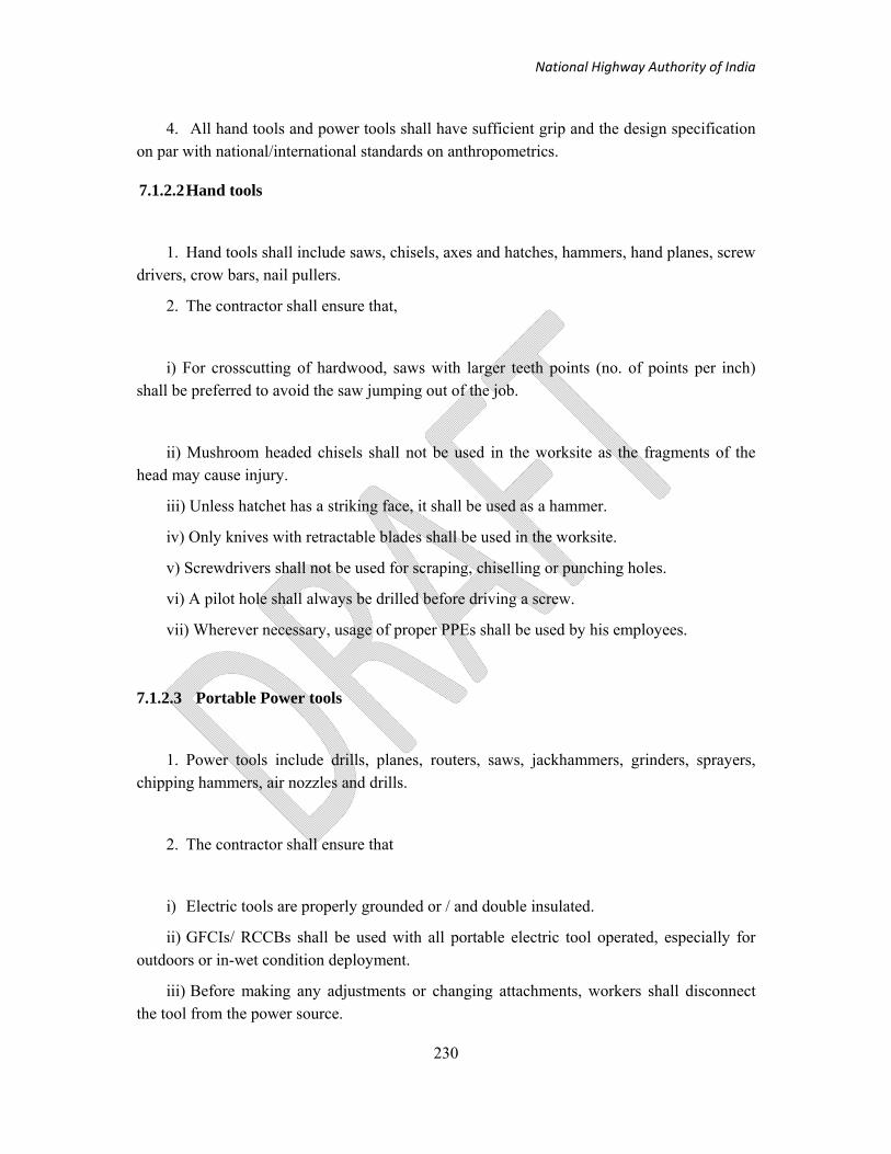
National Highway Authority of India
230
4. All hand tools and power tools shall have sufficient grip and the design specification on par with national/international standards on anthropometrics.
7.1.2.2 Hand tools
1. Hand tools shall include saws, chisels, axes and hatches, hammers, hand planes, screw drivers, crow bars, nail pullers.
2. The contractor shall ensure that,
i) For crosscutting of hardwood, saws with larger teeth points (no. of points per inch) shall be preferred to avoid the saw jumping out of the job.
ii) Mushroom headed chisels shall not be used in the worksite as the fragments of the head may cause injury.
iii) Unless hatchet has a striking face, it shall be used as a hammer.
iv) Only knives with retractable blades shall be used in the worksite.
v) Screwdrivers shall not be used for scraping, chiselling or punching holes.
vi) A pilot hole shall always be drilled before driving a screw.
vii) Wherever necessary, usage of proper PPEs shall be used by his employees.
7.1.2.3 Portable Power tools
1. Power tools include drills, planes, routers, saws, jackhammers, grinders, sprayers, chipping hammers, air nozzles and drills.
2. The contractor shall ensure that
i) Electric tools are properly grounded or / and double insulated.
ii) GFCIs/ RCCBs shall be used with all portable electric tool operated, especially for outdoors or in-wet condition deployment.
iii) Before making any adjustments or changing attachments, workers shall disconnect the tool from the power source.

National Highway Authority of India
231
iv) When operating in confined spaces or for prolonged periods, hearing protection shall be required. The same shall also apply to working with equipments, which gives out noise as mentioned in clause 43.0 of this contract document.
v) Tool is to be held firmly and the material properly secured before powering on the tool.
vi) All drills shall have suitable attachments respective of the operations and powerful for ease of operation.
vii) When any work / operation is to be performed repeatedly or continuously, tools specifically designed for that work shall be used. The same is applicable to detachable tool bits as well.
viii) Largest size of the drill shall be determined by the maximum specified opening of the chuck in case of drill machines.
ix) Attachments such as speed reducing screwdrivers and buffers are to be used to prevent fatigue and undue muscle strain to workers.
x) Before cutting is initiated, stock should be clamped or otherwise secured firmly to prevent it from moving.
xi) Workers standing on top of the ladder to drill holes in walls / ceilings, is a hazardous practice. Using a taller ladder and standing on the fourth or fifth rung is suggested.
xii) Electric planer should not be operated wearing loose clothing, long scarf or open jacket.
xiii) Safety guards used on right angle head or vertical portable grinders must cover a minimum of 1800 of the wheel and the spindle / wheel specifications shall be checked.
xiv) All power tools / hand tools shall have guards at their nip points.
xv) Low profile safety chains should be used in case of wood working machines. High rpm saws should be used and the chain tension should be checked against specifications to avoid “kickback”.
xvi) Leather aprons and gloves shall be used as an additional personal protection auxiliary to withstand kickback.
xvii) Push sticks shall be provided and properly used to hold the job down on the table while the heels moves the stock forward and thus preventing kickbacks.
xviii) Air pressure is set at a suitable level for air actuated tool or equipment being used. Before changing or adjusting pneumatic tools, air pressure is to be turned off.

National Highway Authority of India
232
xix) Only trained employees shall use explosive actuated tools and the tool is to be unloaded when not in use.
xx) Usage of such explosive actuated tools shall be avoided in places where explosive/flammable vapours or gases may be present.
xxi) Explosive actuated tools and their explosives shall be stored separately and be taken out and loaded immediately before use.
xxii) Misfired cartridges of explosive actuated tools must not be reused, placed in a container of water removed safely from the site.
xxiii) No worker shall point any power operated / hand tool to any other person, even during loading / unloading.
7.1.3 Safety in Gas Cutting and Welding
1 Gas cylinders in use shall be kept upright on a custom-built stand or trolley fitted with a bracket to accommodate the hoses and equipment or otherwise secured. The metal cap should be in place to protect the valve when the cylinder is not connected for use.
2 Hose clamp or clips should be invariably used to connect hoses firmly in both sides of cylinders and torches.
3 All gas cylinders shall be fixed with pressure regulators attached with a display of the pressure.
4 Non-return valve and flashback arrester shall be attached both at the end of cylinder and the torch.
5 Domestic LPG cylinders shall not be used for gas welding and cutting purposes.

National Highway Authority of India
233
6 DCP or CO2 type Fire Extinguisher, of size not less than 5 kg should be available at or near to welding process zone in an easily accessible location. Fire Extinguisher should conform to IS 2190: 1992.
7 Use firewatchers if there is a possibility of ignition in zones outside the view of the operator (e.g. on the other side of bulkheads).
8 Oxygen cylinders and flammable gas cylinders shall be stored separately, at least 6.6 meters (20 feet) apart or separated by a fire proof, 1.6 meters (5 feet) high partition. Other flammable substances shall not be stored within 50 feet of cylinder storage areas.
9 Transformer used for electrical arc welding should display current amperage and voltage and have a main power switch separate from that at the electrical outlet.
10 Welding grounds and returns should be securely attached to the work by cable lugs, by clamps in the case of stranded conductors, or by bolts for strip conductors. Attaching the ground cable to other pre-installed equipment or apparatus is not permitted.
11 Use a low voltage open circuit relay device if welding with alternating current in constricted or damp places is suggested.
12 Take precautions against the risk of increased fume hazards when welding with fluxes containing chromium, high current metal inert gas (MIG) or tungsten inert gas (TIG) processes.
13 Avoid being in contact with water or wet floors when welding. Use duckboards or rubber protection.
14 All electrical installations shall meet the IS: 5571: 1997 and NFPA 70 for gas cylinder storage area and other hazardous areas.
15 The current for Electric arc welding shall not exceed 300 A on a hand welding operation.

National Highway Authority of India
234
7.1.4 Safety in Electricity Generation, Distribution, and use
1 Competency of Electrical personnel:
1.1 The contractor shall employ qualified and competent electrical personnel as
specified in general instruction DMRC/SHE/GI/001/MPR/281105.
2 Assessment of power
2.1 The contractor shall assess the size and location of the electrical loads and the manner in which they vary with time during the currency of the contract.
2.2 The contractor shall elaborate as to how the total supply is to be obtained / generated.
The details of the source of electricity, earth requirement, substation / panel boards,
distribution system shall be prepared and necessary approval from the employer obtained
before proceeding on the execution of the job.
2.3 The main contractor shall take consideration, the requirements of the sub / petty
contractors’ electric power supply and arrive at the capacity of main source of
power supply.
2.4 Sub / petty contractors’ should draw power from the overall supply and deployment of small capacity diesel generators is not recommended.
3 Work on site
3.1 Electrical single line diagram, schematic diagram and the details of the equipment for all temporary electrical installation including temporary electrical equipment shall be approved by qualifying authority.

National Highway Authority of India
235
4 Strength and capability of electrical equipment
4.1 No electrical equipment shall be put into use where its strength and capability may be
exceeded in such a way as may give rise to danger.
5 Adverse or hazardous environments
5.1 Electrical equipment which may see foreseeable exposure to-
(a) mechanical damage;
(b) the effects of the weather, natural hazards, temperature or pressure;
(c) the effects of wet, dirty, dusty or corrosive conditions; or
(d) any flammable or explosive substance, including dusts, vapours or gases,
shall be of such construction or necessarily protected as to prevent, so far as is reasonably practicable, danger arising from such exposure.
6 Distribution system:
6.1 The contractor shall provide distribution system for control and distribution of electricity from a main AC supply of 50Hz for typical appliances,
i) Fixed plant – 400V 3 phase
ii) Movable plant fed via trailing cable over 3.75 kW – 400 3 phase
iii) Installation in site buildings – 230V single phase
iv) Fixed flood lighting – 230V single phase
v) Portable and hand tools – 115V single phase
vi) Site lighting - 115V single phase
vii) Portable hand lamps – 115V single phase
7 Electrical protection circuits
7.1 Precautions shall be taken, either by earthing or by other suitable means, to prevent danger arising when any conductor (other than a circuit conductor) becoming charged as a

National Highway Authority of India
236
result of either the use of a system, or a fault in a system. A conductor shall be regarded as earthed when conductors of sufficient strength and current-carrying capability to discharge electrical energy to earth connect it to the general mass of the Earth.
Specifically, the ground resistance must have a maximum value of 2.0 Ω when using the three-point test method at six monthly intervals. Measurement using a two-point multi-meter is not appropriate.
If a circuit conductor is connected to earth or to any other reference point, attachments which might reasonably be expected to give rise to danger by breaking the electrical continuity or introducing high impedance should not be placed in that conductor unless suitable precautions are taken to prevent that danger.
7.2 Appropriate electrical protection shall be provided for all circuits, against overload, short circuit and earth fault current.
7.3 The contractor shall provide sufficient ELCBs (maintain sensitivity of 30 mA) / RCCBs for all the equipments (including Potable equipments), electrical switchboards, distribution panels etc. to prevent electrical shocks to the workers.
7.4 All protection devices shall be capable of interrupting the circuit without damage to any equipment and circuits in case of failure of a subsystem.
7.5 Rating of fuses and circuit breakers used for the protection of circuits should be in accordance to equipment power ratings.
7.6 Protection against lightning strike shall be ensured for all equipment kept in the open at sites.
7.7 Earth conductors are to be checked for continuity and tightness.
8 Cables:
8.1 Cables shall be selected after full consideration of the condition to which they shall be exposed and the duties for which they are required. Supply cable up to 3.3 kV shall be in accordance with BS 6346.
National Highway Authority of India
237
8.2 For supplies to mobile or transportable equipment where operating of the equipment subjects the cable to flexing, the cable shall conform to BS 6007 / BS 6500 / BS 7375 codes.
8.3 Flexible cords with a conductor cross sectional area smaller than 1.5 mm2 shall not be used and insulated flexible cable shall conform to BS 6500 and BS 7375.
8.4 Where low voltage cables are to be used, reference shall be made to BS 7375. The following standards shall also be referred to particularly for underground cables BS 6346 and BS 6708
8.5 Cables buried directly in the ground shall be of a type incorporating armour or metal sheath or both. Such cables shall be marked by cable covers or a suitable marking tape and be buried at a sufficient depth to avoid their being damaged by any disturbance of the ground. Cable routes shall be marked on the plans kept in the site electrical register.
8.6 Cables passing under assigned walkways and across ways for transport and mobile equipment shall be laid in ducts at a minimum depth of 0.6 meters.
8.7 Cables that need to cross open areas, or where span of 3m or more are involved, should be supported by catenary wires on poles or other supports shall be provided for convenient means of suspension. Minimum height shall be 6 m above ground.
8.8 Cables carrying a voltage to earth in excess of 65V other than supply for welding process shall have metal armour or sheath, which has been effectively earthed and monitored by the contractor. In case of flexible and trailing cables such earthed metal sheath and/or armour should be in addition to the earth core in the cable which should not be used as the protective conductor.
8.9 Armoured cables having an over-sheath of polyvinyl chloride (PVC) or an oil resisting and flame retardant compound shall be used whenever there is a risk of mechanical damage occurring

National Highway Authority of India
238
9 Plugs, socket-outlets and couplers:
9.1 The contractor shall ensure plugs, socket-outlets, and couplers available in the construction site to be the “splash proof” type. The minimum degree of Ingress Protection should be of IP44 in accordance with BS EN 60529.
9.2 Only plugs and fittings of the weatherproof type shall be used and they should be colour coded in accordance with the Internationally recognised standards for example as detailed below:
(a) 110 volts : Yellow.
(b) 240 volts : Blue.
(c) 415 volts : Red.
10 Connections
10.1 Every joint and connection in a system shall be mechanically and electrically suitable for use to prevent danger. Proper cable connectors as per national/international standards shall only be used to connect cables.
10.2 No loose connections or taped joints are to be used anywhere in the work site, office area, stores and other areas.
11 Portable and hand-held equipments:
11.1 The contractor should use only double insulated or all-insulated portable electrical hand equipment without earthing (i.e. two core cables). It is recommended that only 110V tools be used without earthing because of the risk of damage to trailing leads.
12 Other equipments:
12.1 All equipment shall have the provision for power switch/cut-off switch in the equipment itself.

National Highway Authority of India
239
12.2 All non-current carrying metal parts of electrical equipment should be earthed through an insulated cable
12.3 Isolate exposed high-voltage (over 415 Volts) equipment, such as transformer banks, open switches, and similar equipment with exposed energized parts and prevent unauthorised access.
12.4 Approved perimeter markings shall be used to isolate restricted areas from designated work areas and entryways and shall be erected before work begins and maintained for entire duration of work. Approved perimeter marking shall be installed with either red barrier tape printed with the words "DANGER—HIGH VOLTAGE" or a barrier of yellow or orange rope, 1 to 1.5 meter above the floor or work surface.
13 Work on or near live conductors
13.1 No person shall be engaged in any work activity on or so near any live conductor (other than one suitably covered with insulating material so as to prevent danger) unless:
a) it is unreasonable in all the circumstances for it to be dead; and
b) it is reasonable in all the circumstances for him to be at work on or near it while it is live; and
c) suitable precautions (including where necessary the provision of suitable protective equipment) are taken to prevent injury.
14 Inspection and Maintenance
14.1 All electrical equipment should be permanently numbered and a record kept of the date of issue, date of last inspection and recommended inspection period.
14.2 Fixed installations shall be inspected at least at three monthly intervals; routine maintenance being carried out in accordance with equipment manufactures recommendations.
National Highway Authority of India
240
7.2 Construction Plants Safety
The contractor shall ensure that every construction plant shall be in sound working condition and certified by either Manufacturers warranty in case of brand new plant or competent person under Factories Act. Such certificates shall have the records of pertinent data such as date of purchase, accident to the plant if any, overhauling if any in the past, visual examination details, and safety check list of critical components. The contractor shall maintain a work permit system for the maintenance of movable part of batching plant, hot mix plant etc. as per the details given in the following section.
7.2.1 Maintenance and Work Permit System
1 The Contractor shall develop a Work Permit system, which is a formal written system used to control certain types of work that are potentially hazardous. A work permit is a document, which specifies the work to be done, and the precautions to be taken. Work Permits form an essential part of safe systems of work for many construction activities. They allow work to start only after safe procedures have been defined and they provide a clear record that all foreseeable hazards have been considered. Permits to work are usually required in high-risk areas as identified by the Risk Assessments.
2 A permit is needed when construction work can only be carried out if normal safeguards are dropped or when new hazards are introduced by the work. Examples of high-risk activities include but are not limited to:
i) Entry into confined spaces
ii) Work in close proximity to overhead power lines and telecommunication cables.
iii) Hot work.
iv) Digging in vicinity of location of underground services.
v) Work with heavy moving machinery.
vi) Work with electrical equipment
vii) Work with radioactive isotopes.
viii) Heavy lifting operations and lifting operations closer to live power lines
3 The permit-to-work system should be fully documented, specifying:
i) How the system works;

National Highway Authority of India
241
ii) The jobs the work permit is applicable for;
iii) The responsibilities and training of those involved; and
iv) How to check execution of the work permit procedure
4 A Work-Permit authorization shall be valid for a duration not exceeding 12 hours.
5 A copy of each Permit to Work shall be displayed, during its validity, in a conspicuous location in close proximity to the actual works location to which it applies.
7.3 Fire Safety
1 The contractor shall ensure that construction site is provided with fire extinguishing equipment sufficient to extinguish any probable fire at construction site. An adequate water supply is provided at ample pressure as per national standard.
2 Recharging of fire extinguishers and their proper maintenance should be ensured and as a minimum should meet Indian National Standards
3 All drivers of vehicles, foreman, supervisors and managers shall be trained on operating the fire extinguishers and firefighting equipment.
4 The contractor shall also give consideration to the provision of additional, adequate, fire fighting arrangements during underground and tunneling operations including the provision of Fire Service compatible hose connections and emergency lighting.
5 As per the DBOCW Rules 2002, Rule 63(a)(vii), for all lifting appliances, the driver cabin should be provided with a suitable portable fire extinguisher.
6 Combustible scrap and other construction debris should be disposed offsite on a regular basis. If scrap is to be burnt on site, the burning site should be specified and located at a distance no less than 12 meters from any construction work or any other combustible material.
7 Every fire, including those extinguished by contractor personnel, shall be reported to the Employer representatives.

National Highway Authority of India
242
APPENDIX -I i. Checklists for Traffic Management Arrangements
ANNEXURE-1 Audit Check Lists: 1. TRAFFIC MANAGEMENT AND SAFETY (TS) Contract Document: MORTH Clause 112 and Technical Specifications
Package No. Chainage:
Contractor Location:
Part A: Documentation Audit
S. No. Aspect Reference Question Compliance Observations Remarks
1.
Traffic Management (Sub Clause 112.1)
Are Traffic Management Plans (TMPs) (including diversion drawings) being prepared and submitted by the Contractor to the Engineer for approval?
Is the TMP site/section specific? Are the TMP submissions being made in time? Does the TMP/drawing clearly show the traffic safety arrangements both for
day and night?
Does the TMP reflect necessary safety provisions for pedestrians and local residents?
Is the contractor initiating any work without the necessary TMP approval in place?
Is the CSC ensuring the required quality of the TMP?
Is the approval being given before the initiation of work on sites? Are temporary diversions at new bridges approved by the Engineer?
2
Traffic Safety Measures (Sub clause 112.4)
Are there any persistent breaches of safety provisions by the Contractor? Has the Engineer/CSC taken the required action to ensure/improve
Compliance?
112.3 Has the alignment and longitudinal section of diversion including junctions and temporary cross drainage provisions approved by the Engineer?

National Highway Authority of India
243
Part B: Field Audit S. No. Aspect Reference Question Compliance Observations Remarks
1.
Maintenance of Diversions and Traffic Control Devices
112.4 and 112.5
Are the following devices as per the specifications a) Barricades ( barricades strong enough to resist violation, painted with alternate black and white stripes, and mounted with lights )
b) Signage – General
c) Signage – Diversions
d) Markings (pavement markings, painted drums or similar devices)
e) Flags and flagmen
f) Lights
Dust suppression by frequent sprinkling of water Have safety measures been provided at/near existing highway crossings of other categories (eg: State highway (SH), MDRs, Local Roads?)
Are the night time safety arrangements appropriate?
Is the actual diversion on the site is in compliance with TMP?
2
Widening and Strengthening of the existing carriageway (Road Maintenance)
112.2
Is the carriageway maintenance satisfactory and free of potholes?
Is the haul road maintenance satisfactory?
Is there a minimum of 5.5 m wide and not more than 750 m long open for traffic at all times?
3
Traffic Passage on temporary diversion (Sub Clause 112.3)
112.3
NH/SH: 7.0 m (carriageway) +2.5 m shoulder (unpaved) MDR/ODR: 5.25 m (carriageway) +1.0 m shoulder (unpaved) VR/Cart Roads: 3.25 m (carriageway) +1.0 m shoulder (unpaved)

National Highway Authority of India
244
ii. Compliance Calculations
The contractual and legal compliances are computed in quantitative terms based on the check list. This is computed in two parts: document compliance and field compliance. The method for computing compliances for each one of them is described below:
a) Document compliance
The audit team asks for the document as per the part A of the check list of the respective audit sector. For compliance, 1 point is awarded while for non compliance, 0 point is awarded. In case, some check list points are not applicable, the same is not taken into account in the computation procedure. Based on the number of ‘1’ and ‘0’ obtained, the contractual compliance percentage is obtained. Corresponding to every reading of ‘1’ the audit team also makes further distinction: ‘1’ for ‘average compliance’ and ‘2’ for ‘good compliance’.
b) Field compliance
The audit team visits site and as per the part B of the check list of the respective audit sector, checks the compliance. For compliance, ‘1’ is awarded while for non compliance ‘0’ is awarded. In case, some check list points are not applicable, the same is not taken into account in the computation procedure. Based on the number of ‘1’and ‘0’ obtained, the contractual compliance percentage is obtained. Corresponding to every reading of ‘1’ the audit team also makes further distinction: ‘1’ for ‘average compliance’ and ‘2’ for ‘good compliance’.
The compliance percentages are calculated on the basis of number of ‘yes’ and ‘no’ compared to the total responses in each check list.

National Highway Authority of India
245
iii. Taper Length calculations
• Taper length L (m) = N x I
• N = Recommended ratio for taper length
• I (m) = lateral shift of the horizontal alignment from the original line.
• Xn (m) = Length at n location = A x L, A = 0.00, 0.05, 0.10, ........, 1.00
• Yn (m) = off-set from reference line at n location = En x I
• En: coefficient
Table 1 Taper Length for merging taper (2 to 1 lane for I = 3.5m)
Design Speed
N N × I Proposed Length L1
0.05 × L1 0.1 × L1
Km/h - (m) (m) (m) (m) (1) (2) (3) (4) (5) (6) 80 40 140 140 7 14 65 25 87.5 90 4.5 9 50 10 35 40 2 4 40 5 17.5 20 1 2
Table 2 Taper Length for shifting taper (I = 3.5m)
Design Speed
N N × I Proposed Length L2
0.05 × L2 0.1 × L2
Km/h - (m) (m) (m) (m) (1) (2) (3) (4) (5) (6) 80 20 70 70 3.5 7 65 13 45.5 50 2.5 5 50 5 17.5 20 1 2 40 3 10.5 10 0.5 1

National Highway Authority of India
246
Table 3 Calculation of En for short and long term work
A* En
0.00 0.00
0.10 0.125
0.20 0.250
0.30 0.375
0.40 0.500
0.50 0.625
0.60 0.750
0.65 0.810
0.70 0.855
0.75 0.910
0.80 0.935
0.85 0.965
0.90 0.980
0.95 0.995
1.00 1.00
*Closer spacing for shorter taper length
Example: Setting-out of merging taper for 2 lanes to one lane
• Expressway: V = 80 kph
• N = 40
• Reducing width: I = 3.5m
• Min Taper length: L = N x I = 40 x 3.5 = 140m
• Chosen Taper length: L = 160m for easy setting out. 0.1L = 16m, 0.05L = 8m

National Highway Authority of India
247
Table 4 Setting out for merging taper (2 to 1 for I = 3.5m)
A L Xn = A × L En I Yn = En × I
- (m) (m) - (m) (m)
(1) (2) (3) (4) (5) (6)
0.0 160 0 0.00 3.5 0
0.1 160 16 0.125 3.5 0.43
0.2 160 32 0.250 3.5 0.88
0.3 160 48 0.375 3.5 1.31
0.4 160 64 0.500 3.5 1.75
0.5 160 80 0.625 3.5 2.19
0.6 160 96 0.750 3.5 2.63
0.7 160 112 0.855 3.5 2.99
0.8 160 128 0.935 3.5 3.27
0.9 160 144 0.980 3.5 3.43
1.0 160 160 1.00 3.5 3.50
• min L = V x ( I/3)0.5 , Recommended L = N x I • V (kph) = Design speed e.g. 80 kph • I (m) = change in width to carriage-way e.g. 3.5m • L (m) = Taper length = N x I, min L = 80 x (3.5/3)0.5 = 80 x 1.0817 = 86.54 • Xn (m) = length at n location A x L, A = 0.00, 0.05, 0.10, ........, 1.00. • Yn (m) = off-set from reference line at n location = En x I
• En: coefficient

National Highway Authority of India
248
Table 5 Calculation of En for extended Long Term work and Complicated Traffic diversion
A* En
0.00 0.00
0.05 0.005
0.10 0.020
0.15 0.045
0.20 0.080
0.25 0.125
0.30 0.180
0.35 0.245
0.40 0.320
0.45 0.405
0.50 0.500
0.55 0.595
0.60 0.680
0.65 0.755
0.70 0.820
0.75 0.875
0.80 0.920
0.85 0.955
0.90 0.980
0.95 0.995
1.00 1.000
*Closer spacing for shorter taper length

National Highway Authority of India
249
Example: Setting-out data for reducing 3.5m width of an expressway (80kph).
Taper length L = 160m 0.1L = 16m 0.05L = 8m.
Table 6 Setting out for merging taper (2 to 1 for I = 3.5 m)
A L Xn = A × L En I Yn = En × I
- (m) (m) - (m) (m)
(1) (2) (3) (4) (5) (6)
0.0 160 0 0.00 3.5 0.00
0.1 160 16 0.02 3.5 0.07
0.2 160 32 0.08 3.5 0.28
0.3 160 48 0.18 3.5 0.63
0.4 160 64 0.32 3.5 1.12
0.5 160 80 0.50 3.5 1.75
0.6 160 96 0.68 3.5 2.38
0.7 160 112 0.72 3.5 2.52
0.8 160 128 0.92 3.5 3.22
0.9 160 144 0.98 3.5 3.43
1.0 160 160 1.00 3.5 3.50

National Highway Authority of India
250
iv. Modules (for calculation of traffic signs/delineation devices) for 100m Work Zone for TMPs
4.1 Figure titled: “Traffic control by Give and Take System”
S.No. Traffic Signs/Delineation Devices
↑ Directio
n
↓ Direction
1
Men at work 1
1
2
Diversion 1 None
3
End of Work Zone
1 1
4 Reduced Carriage Way
1 1
5 Compulsory Keep Left
1 None
6 Compulsory Keep Right
1 None
7 Speed Limit (30 kmph)
1 1
8 Rumble strips@80m cc
4 4
9
STOP / GO Board For Priority Traffic 1 1
10 Traffic Cones 18 None
11 Traffic Cylinder/Drums/Bollard 15 None
12 Portable VMS/Roll up sign 2 None
13 Plastic Barricades 102 None
14 Blinkers 102 None

National Highway Authority of India
251
4.2 Figure Titled: “Traffic Control by STOP/GO Board”
S.No. Traffic Signs/Delineation Devices
↑ Directio
n
↓ Directio
n
1
Men at work 1
1
2
Diversion 1 None
3
End of Work Zone
1 1
4 Reduced Carriage Way
1 1
5 Compulsory Keep Left
1 None
6 Compulsory Keep Right
1 None
7 Speed Limit (30 kmph)
1 1
8 Rumble strips@80m cc
4 4
9
STOP / GO Board For Priority Traffic 1 1
10
Traffic Cones 18 None
11 Traffic Cylinders/ Drums/Bollard 15 None
12 Portable VMS/Roll up sign 2 None
13 Plastic Barricades 102 None
14 Blinkers 102 None

National Highway Authority of India
252
4.3 Figure titled: “Basic Layout”
S.No. Traffic Signs/Delineation Devices
↑ Directio
n
↓ Direction
1
Men at work 1
1
2
Diversion 1 None
3
End of Work Zone
1 1
4 Reduced Carriage Way
1 1
5 STOP / GO Board For Priority Traffic
1 None
6 Compulsory Keep Left
1 None
7 Compulsory Keep Right
1 None
8 Speed Limit (30 kmph)
1 1
9 Rumble strips@80m cc
4 4
10
Traffic Cones 18 None
11 Traffic Cylinder/Drums 15 None
12 Portable VMS/Roll up sign 2 None
13 Plastic Barricades 102 None

National Highway Authority of India
253
4.4 Figure titled: “Traffic Control by portable Traffic Signals”
S.No Traffic Signs/Delineation Devices ↑ Direction
↓ Direction
1 Men at work 1 1
2 Diversion 1 None
3 End of Work Zone 1 1
4 Reduced Carriage Way 1 1
5 Compulsory Keep Left 1 None
6 Compulsory Keep Right 1 None
7 Traffic Signal Ahead 1 1
8 Traffic Signal 1 1
9 Stop (At Red Light) 1 1
10 Speed Limit (30 kmph) 1 1
11 Rumble strips@80m cc 4 4
12 STOP / GO Board For Priority Traffic 1 1
13 Traffic cones 18 None
14 Traffic Cylinder/Drums/Bollard 15 None
15 Portable VMS/Roll up sign 2 None
16 Plastic Barricades 102 None
17 Blinkers 102 None

National Highway Authority of India
254
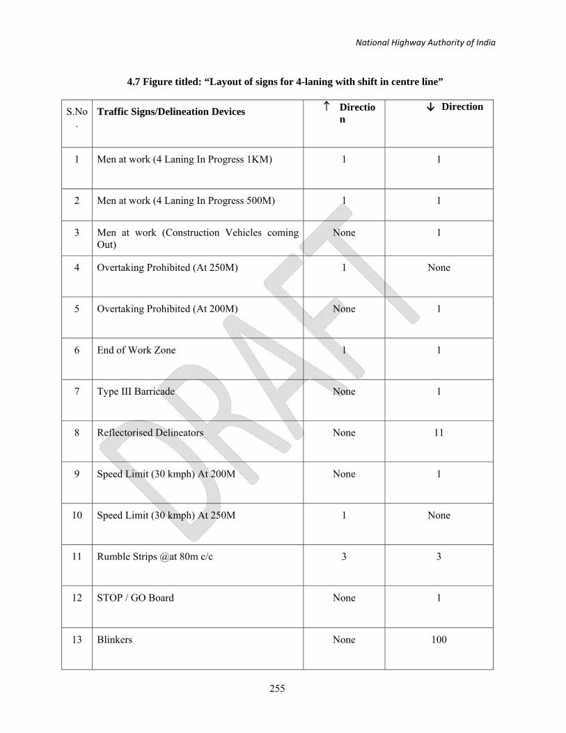
National Highway Authority of India
255
4.7 Figure titled: “Layout of signs for 4-laning with shift in centre line”
S.No.
Traffic Signs/Delineation Devices
↑ Direction
↓ Direction
1
Men at work (4 Laning In Progress 1KM) 1
1
2 Men at work (4 Laning In Progress 500M) 1 1
3 Men at work (Construction Vehicles coming Out)
None 1
4
Overtaking Prohibited (At 250M) 1 None
5 Overtaking Prohibited (At 200M)
None 1
6
End of Work Zone
1 1
7 Type III Barricade
None 1
8 Reflectorised Delineators
None 11
9 Speed Limit (30 kmph) At 200M
None 1
10 Speed Limit (30 kmph) At 250M
1 None
11 Rumble Strips @at 80m c/c
3 3
12
STOP / GO Board None 1
13 Blinkers None 100

National Highway Authority of India
256
4.8 Figure titled: “Layout of signs and control devices for change in carriageway usage”
S.No. Traffic signs/Delineation Devices
↑ Directio
n
↓ Directio
n1 Men at work (4 Laning In Progress 1KM) 1 1
2 Diversion To Other Carriageway (at 750 M) 1 1
3 Diversion 2 2
4 End of Work Zone 1 1
5 Lane closed (Two lane Road) at 500 M 1 1
6 Compulsory Turn Right (at 125 M) 1 1
7 Overtaking Prohibited (at 250 M) 1 1
8 Speed Limit (30kmph) 2 2
9 Rumble strips@80m cc 2 2
10 Stop/Go Board For Priority Traffic 1 1
11 Traffic Cones 10 10
12 Traffic Cylinder/Drums/Bollard 8 8
13 Portable VMS/ Roll up sign 2 2
14 Plastic Barricades 13 13
15 Blinkers 13 13

National Highway Authority of India
257
4.9 Figure titled: “Traffic control by Priority signs”
S.No Traffic signs/Delineation Devices ↑ Direction ↓ Direction
1 Men at work 1 1
2 Diversion 1 None
3 End of Work Zone 1 1
4 Compulsory Keep Left 1 None
5 Compulsory Keep Right 1 None
6 Reduced Carriage Way 1 1
7 Priority to Vehicles In Other Direction 1 None
8 Priority to Vehicles In this Direction None 1
9 Speed Limit (30kmph) 1 1
10 Rumble strips@80m cc 4 4
11 Traffic Cones 18 None
12 Stop/Go Board For Priority Traffic 1 1
13 Traffic Cylinder/Drums/Bollard 15 None
14 Portable VMS/ Roll up sign 2 None
15 Plastic Barricades 102 None
16 Blinkers 102 None

National Highway Authority of India
258
4.10 Figure titled: “Co-centric widening: Stage I – construction of new lanes”
S.No.
Traffic signs/Delineation Devices
↑ Direction
↓ Direction
1
Men at work (4 Laning In Progress 1KM) 1
1
2 Men at work (4 Laning In Progress 500 M) 1 1
3 Men at work (Construction Vehicles coming Out) 1 1
4
Diversion None None
5
End of Work Zone
1 1
6 Speed Limit (30kmph) (at 250M)
1 1
7 Rumble strips@80m cc
3 3
8
Overtaking Prohibited (at 250M) 1 1
9
Compulsory keep Right 1 1
10 Blinkers
100 100

National Highway Authority of India
259
4.11 Figure titled: “Co-centric widening: Stage II – Strengthening of existing carriageway and median construction”
S.No.
Traffic signs/Delineation Devices
↑ Direction
↓ Direction
1
Men at work (4 Laning In Progress 1KM) 1
1
2 Men at work (4 Laning In Progress 500 M) 1 1
3 Men at work (Construction Vehicles coming Out) 1 1
4
Diversion 1 1
5
End of Work Zone
1 1
6 Compulsory Keep Left
1 1
7 Overtaking Prohibited at 250M
1 1
8 Speed Limit (30kmph)
2 2
9 Rumble strips@80m cc
4 4
10
Stop/Go Board 1 1
11 Blinkers
102 102

National Highway Authority of India
260
4.12 Figure titled: “Co-centric widening: Stage III – Shifting of work zone”
S.No.
Traffic signs/Delineation Devices
↑ Direction
↓ Direction
1
Men at work (4 Laning In Progress 1KM) 1
None
2 Men at work (4 Laning In Progress 500 M) 1 None
3 Men at work (Construction Vehicles coming Out) 1 1
4
Diversion None 1
5 Divided Road
1 1
6
End of Work Zone
1 1
7 Compulsory Keep Right
1 None
8 Overtaking Prohibited
1 1
9 Speed Limit (30kmph)
1 1
10 Rumble strips@80m cc
4 4
11
Stop/Go Board 1 1
12 Divided Road End 1 1
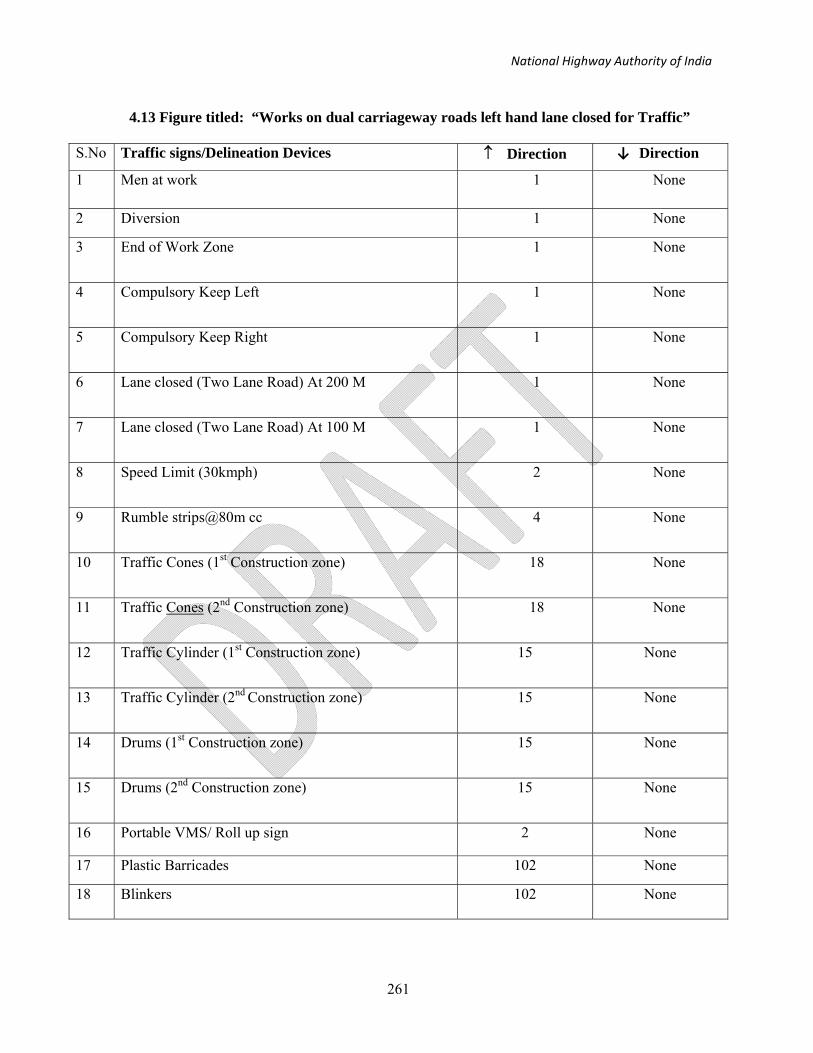
National Highway Authority of India
261
4.13 Figure titled: “Works on dual carriageway roads left hand lane closed for Traffic”
S.No Traffic signs/Delineation Devices ↑ Direction ↓ Direction
1
Men at work 1
None
2 Diversion 1 None
3
End of Work Zone
1 None
4 Compulsory Keep Left
1 None
5 Compulsory Keep Right
1 None
6 Lane closed (Two Lane Road) At 200 M
1 None
7 Lane closed (Two Lane Road) At 100 M
1 None
8 Speed Limit (30kmph)
2 None
9 Rumble strips@80m cc
4 None
10
Traffic Cones (1st Construction zone)
18 None
11 Traffic Cones (2nd Construction zone)
18 None
12 Traffic Cylinder (1st Construction zone)
15 None
13 Traffic Cylinder (2nd Construction zone)
15 None
14 Drums (1st Construction zone)
15 None
15 Drums (2nd Construction zone)
15 None
16 Portable VMS/ Roll up sign
2 None
17 Plastic Barricades 102 None
18 Blinkers
102 None

National Highway Authority of India
262
4.14 Figure titled: “Works on dual carriageway roads right hand lane closed for Traffic”
S.No.
Traffic signs/Delineation Devices ↑ Direction
↓ Direction
1 Men at work at 300M 2 None
2 Diversion 1 None
3 End of Work Zone 1 None
4 Compulsory Keep Left 1 None
5 Lane closed (Two Lane Road) At 200 M 2 None
6 Lane closed (Two Lane Road) At 100 M 2 None
7 Speed Limit (30kmph) 1 None
8 Rumble strips@80m cc 5 None
9 Traffic Cones 18 None
10 Traffic Cylinder/Drums/Bollard 15 None
11 Portable VMS/ Roll up sign 2 None
12 Plastic Barricades 102 None
13 Blinkers 102 None
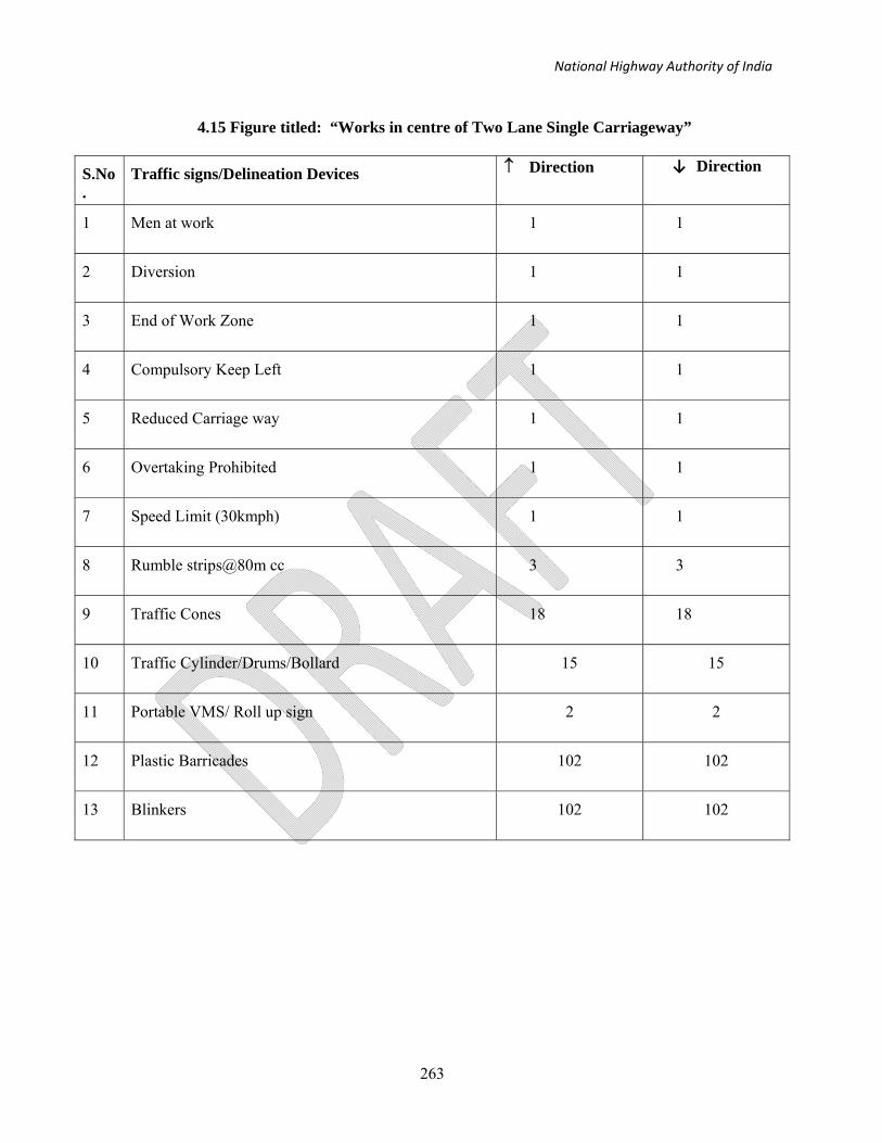
National Highway Authority of India
263
4.15 Figure titled: “Works in centre of Two Lane Single Carriageway”
S.No.
Traffic signs/Delineation Devices ↑ Direction
↓ Direction
1 Men at work 1 1
2 Diversion 1 1
3 End of Work Zone 1 1
4 Compulsory Keep Left 1 1
5 Reduced Carriage way 1 1
6 Overtaking Prohibited 1 1
7 Speed Limit (30kmph) 1 1
8 Rumble strips@80m cc 3 3
9 Traffic Cones 18 18
10 Traffic Cylinder/Drums/Bollard 15 15
11 Portable VMS/ Roll up sign 2 2
12 Plastic Barricades 102 102
13 Blinkers 102 102

National Highway Authority of India
264
4.16 Figure titled: “Expressway without hard shoulder. Lane adjacent to median closed for Traffic”
S.No.
Traffic signs/Delineation Devices ↑ Direction
↓ Direction
1 Men at work 4 None
2 Diversion 1 None
3 Lane closed (Two Lane Road) at 800m 2 None
4 Lane closed (Two Lane Road) at 600m 2 None
5 Lane closed (Two Lane Road) at 400m 2 None
6 Lane closed (Two Lane Road) at 200m 2 None
7 End of Work Zone 2 None
8 Compulsory Keep Left 1 None
9 Compulsory Keep Right 1 None
10 Speed Limit (50kmph) 2 None
11 Speed Limit (30kmph) 1 None
12 Rumble strips@80m cc 7 None
13 Traffic Cones 18 None
14 Traffic Cylinder/Drums/Bollard 15 None
15 Portable VMS/ Roll up sign 2 None
16 Type Three Barricades 102 None
17 Blinkers 102 None

National Highway Authority of India
265
4.17 Figure titled: “Dual Two Lane Expressway having centre flow with buffer zone between opposing flows. Either hard shoulder used”
S. No.
Traffic signs/Delineation Devices ↑ Direction ↓ Direction
1 Men at work (at 5 KM) 2 2
2 Men at work (at 3.5 KM) 2 2
3 Men at work (at 1.5 KM) 2 2
4 Diversion 1 None
5 End of Work Zone 2 2
6 Speed Limit (30kmph) 2 None
7 Overtaking Prohibited 1 1
8 Speed Limit (50kmph) 1 1
9 Rumble strips@80m cc 3 5
10 Portable VMS/Roll up signs 4 None
11 Lane Closed (Two Lane Road) at 800 m 2 2
12 Lane Closed (Two Lane Road) at 600 m 2 2
13 Lane Closed (Two Lane Road) at 400 m 2 2
14 Lane Closed (Two Lane Road) at 200 m 2 2
15 Works Traffic Access Only 1 1
16 Traffic Cones 40 24
17 Portable VMS/ Roll up sign 4 None

National Highway Authority of India
266
4.18 Figure titled: “Dual Three lane Expressway with left and centre lane closed”
S.No. Traffic signs/Delineation Devices ↑ Direction
↓ Direction
1 Men at work 6 None
2 Diversion 1 1
3 End of Work Zone 2 None
4 Lane closed (Two Lane Road) at 800m 2 2
5 Lane closed (Two Lane Road) at 600m 2 2
6 Lane closed (Two Lane Road) at 400m 2 2
7 Lane closed (Two Lane Road) at 200m 2 2
8 Works Traffic Access Only 1 None
9 Speed Limit (30kmph) 2 None
10 Speed Limit (50kmph) 2 None
11 Rumble strips@80m cc 7 None
12 Entry For Work Traffic 1 None
13 Traffic Cones 45 None
14 Portable VMS/ Roll up sign 4 None

National Highway Authority of India
267
4.19 Figure titled: “Dual Three lanes Expressway with right and centre lane closed on one carriageway”
S. No. Traffic signs/Delineation Devices ↑ Direction ↓ Direction
1 Men at work (at 5 KM) 2 None
2 Men at work (at 3.5 KM) 2 None
3 Men at work (at 1.5 KM) 2 None
4 Diversion 1 None
5 End of Work Zone 1 None
6 Compulsory Keep right 3 None
7 Compulsory Keep Left 3 None
8 Speed Limit (30Kmph) 1 None
9 Speed Limit (50Kmph) 2 None
10 Lane closed (Three Lane Road) at 800m 2 None
11 Lane closed (Three Lane Road) at 600m 2 None
12 Lane closed (Three Lane Road) at 400m 2 None
13 Lane closed (Three Lane Road) at 800m 2 None
14 Works Traffic Access Only 1 None
15 Rumble strips@80m cc 6 None
16 Traffic Cones 25 None
17 Portable VMS/ Roll up sign 2 None
18 Type Three Barricades 102 102
19 Blinkers 102 102

National Highway Authority of India
268
4.20 Figure titled: “Dual Three lanes Expressway having segregated Contra flow with buffer zones – primary hard shoulders used”
S.No Traffic signs/Delineation Devices ↑ Direction ↓ Direction
1 Men at work (at 5 KM) 2 2
2 Men at work (at 3.5 KM) 2 2
3 Men at work (at 1.5 KM) 2 2
4 Diversion 2 1
5 End of Work Zone 2 1
6 Compulsory Keep right 5 1
7 Compulsory Keep Left 3 3
8 Speed Limit (30Kmph) 2 1
9 Speed Limit (50Kmph) 2 2
10 Lane closed (Three Lane Road) at 800m 2 2
11 Lane closed (Three Lane Road) at 600m 2 2
12 Lane closed (Three Lane Road) at 400m 2 2
13 Lane closed (Three Lane Road) at 800m 2 2
14 Works Traffic Access Only 1 1
15 Rumble strips@80m cc 2 3
16 Portable VMS/ Roll up sign 6 None
17 Traffic cones 27 20

National Highway Authority of India
269
4.21 Figure titled: “Works at Road Junctions”
(a) Major Road
S.No. Traffic signs/Delineation Devices
↑ Direction
↓ Direction
1
Men at work 1
1
(b) Minor Road
S.No. Traffic signs/Delineation Devices ↑ Direction ↓ Direction
1 Men at work 1 None
2 Diversion 1 None
3 Compulsory Keep Right 1 None
4 Reduced Carriage Way 1 None
5 Rumble strips@80m cc 2 None
6 Speed Limit (30kmph) 1 None
7 Stop/Go Board for priority traffic 1 None
8 Traffic cones 18 None
9 Traffic Cylinder/Drums/Bollard 15 None
10 Portable VMS/ Roll up sign 2 None
11 Plastic Barricades 102 None
12 Blinkers 102 None

National Highway Authority of India
270
4.22 Figure titled: “Works on or near the far side of a junction”
(a) Major Road
S.No. Traffic signs/Delineation Devices ↑ Direction ↓ Direction
1 Men at work 1 1
2 Diversion None 1
4 Compulsory Keep Right None 1
5 Reduced Carriage Way 1 1
6 Rumble strips@80m cc 2 2
7 Speed Limit (30kmph) None 1
8 Traffic cones None 32
9 Traffic Cylinder/Drums/Bollard None 26
10 Portable VMS/ Roll up sign None 2
11 Plastic Barricades None 204
12 Blinkers None 204

National Highway Authority of India
271
(b) Minor Road
S.No. Traffic signs/Delineation Devices
↑ Direction
↓ Direction
1
Men at work 1
None
2
Diversion 1 None
3 Compulsory Keep Right
2 None
4 Reduced Carriage Way
1 None
5 Rumble strips@80m cc
2 None
6 Speed Limit (30kmph)
1 None
7
Stop/Go Board for Priority Traffic 1 None
8 Traffic cones 12 None
9 Traffic Cylinder/Drums/Bollard 9 None
10 Portable VMS/ Roll up sign
2 None
11 Plastic Barricades
84 None
12 Blinkers
84 None

National Highway Authority of India
272
4.23 Figure titled: “Layout of signs and Control Devices for Road closed with a Diversion”
S.No Traffic signs/Delineation Devices ↑ Direction ↓ Direction
1 Men at work (4 Laning in Progress 1 KM) 1 1
2 Diversion 1 2
3 End of Work Zone 1 1
4 Compulsory Turn Right 1 None
5 Compulsory Turn Left None 1
6 Overtaking Prohibited 1 1
7 Speed Limit (30kmph) 1 1
8 Rumble strips@80m cc 3 3
9 Chevron None 2
10 Barricade Type III 2 None
11 Road closed 1 1
12 Narrow Bridge Ahead 2 2
13 Traffic Cones 18 14
14 Blinkers 3 3