Safety Function: Actuator Subsystems -- Stop Category 0 ...
16
Application Technique Safety Function: Actuator Subsystems – Stop Category 0 via a Safety Relay and PowerFlex 755 Drive with Hardwired Safe Torque-off Products: Guardmaster Dual-Input Safety Relay, PowerFlex 755 Drive Safety Rating: CAT. 3, PLe to ISO 13849-1: 2008 Topic Page Important User Information 2 General Safety Information 3 Introduction 4 Safety Function Realization: Risk Assessment 4 Stop Safety Functions 4 Safety Function Requirements 5 Functional Safety Description 6 Bill of Material 7 Setup and Wiring 7 Configuration 9 Calculation of the Performance Level 9 Verification and Validation Plan 11 Additional Resources 14
Transcript of Safety Function: Actuator Subsystems -- Stop Category 0 ...

Application Technique
Safety Function: Actuator Subsystems – Stop Category 0 via a Safety Relay and PowerFlex 755 Drive with Hardwired Safe Torque-offProducts: Guardmaster Dual-Input Safety Relay, PowerFlex 755 Drive
Safety Rating: CAT. 3, PLe to ISO 13849-1: 2008
Topic Page
Important User Information 2
General Safety Information 3
Introduction 4
Safety Function Realization: Risk Assessment 4
Stop Safety Functions 4
Safety Function Requirements 5
Functional Safety Description 6
Bill of Material 7
Setup and Wiring 7
Configuration 9
Calculation of the Performance Level 9
Verification and Validation Plan 11
Additional Resources 14

Safety Function: Actuator Subsystems – Stop Category 0 via a Safety Relay and PowerFlex 755 Drive with Hardwired Safe Torque-off
Important User Information
Read this document and the documents listed in the additional resources section about installation, configuration, and operation of this equipment before you install, configure, operate, or maintain this product. Users are required to familiarize themselves with installation and wiring instructions in addition to requirements of all applicable codes, laws, and standards.
Activities including installation, adjustments, putting into service, use, assembly, disassembly, and maintenance are required to be carried out by suitably trained personnel in accordance with applicable code of practice.
If this equipment is used in a manner not specified by the manufacturer, the protection provided by the equipment may be impaired.
In no event will Rockwell Automation, Inc. be responsible or liable for indirect or consequential damages resulting from the use or application of this equipment.
The examples and diagrams in this manual are included solely for illustrative purposes. Because of the many variables and requirements associated with any particular installation, Rockwell Automation, Inc. cannot assume responsibility or liability for actual use based on the examples and diagrams.
No patent liability is assumed by Rockwell Automation, Inc. with respect to use of information, circuits, equipment, or software described in this manual.
Reproduction of the contents of this manual, in whole or in part, without written permission of Rockwell Automation, Inc., is prohibited.
Throughout this manual, when necessary, we use notes to make you aware of safety considerations.
Labels may also be on or inside the equipment to provide specific precautions.
WARNING: Identifies information about practices or circumstances that can cause an explosion in a hazardous environment, which may lead to personal injury or death, property damage, or economic loss.
ATTENTION: Identifies information about practices or circumstances that can lead to personal injury or death, property damage, or economic loss. Attentions help you identify a hazard, avoid a hazard, and recognize the consequence.
IMPORTANT Identifies information that is critical for successful application and understanding of the product.
SHOCK HAZARD: Labels may be on or inside the equipment, for example, a drive or motor, to alert people that dangerous voltage may be present.
BURN HAZARD: Labels may be on or inside the equipment, for example, a drive or motor, to alert people that surfaces may reach dangerous temperatures.
ARC FLASH HAZARD: Labels may be on or inside the equipment, for example, a motor control center, to alert people to potential Arc Flash. Arc Flash will cause severe injury or death. Wear proper Personal Protective Equipment (PPE). Follow ALL Regulatory requirements for safe work practices and for Personal Protective Equipment (PPE).
2 Rockwell Automation Publication SAFETY-AT144A-EN-P - August 2015
Safety Function: Actuator Subsystems – Stop Category 0 via a Safety Relay and PowerFlex 755 Drive with Hardwired Safe Torque-off
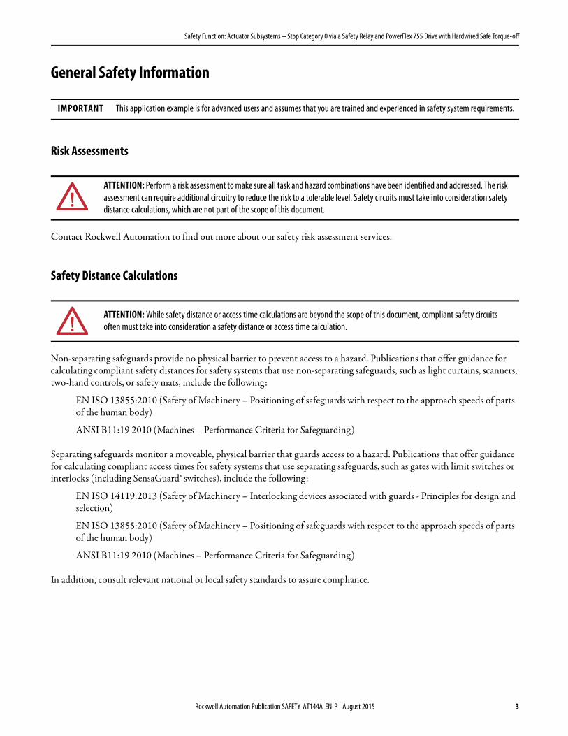
General Safety Information
Risk Assessments
Contact Rockwell Automation to find out more about our safety risk assessment services.
Safety Distance Calculations
Non-separating safeguards provide no physical barrier to prevent access to a hazard. Publications that offer guidance for calculating compliant safety distances for safety systems that use non-separating safeguards, such as light curtains, scanners, two-hand controls, or safety mats, include the following:
EN ISO 13855:2010 (Safety of Machinery – Positioning of safeguards with respect to the approach speeds of parts of the human body)
ANSI B11:19 2010 (Machines – Performance Criteria for Safeguarding)
Separating safeguards monitor a moveable, physical barrier that guards access to a hazard. Publications that offer guidance for calculating compliant access times for safety systems that use separating safeguards, such as gates with limit switches or interlocks (including SensaGuard® switches), include the following:
EN ISO 14119:2013 (Safety of Machinery – Interlocking devices associated with guards - Principles for design and selection)
EN ISO 13855:2010 (Safety of Machinery – Positioning of safeguards with respect to the approach speeds of parts of the human body)
ANSI B11:19 2010 (Machines – Performance Criteria for Safeguarding)
In addition, consult relevant national or local safety standards to assure compliance.
IMPORTANT This application example is for advanced users and assumes that you are trained and experienced in safety system requirements.
ATTENTION: Perform a risk assessment to make sure all task and hazard combinations have been identified and addressed. The risk assessment can require additional circuitry to reduce the risk to a tolerable level. Safety circuits must take into consideration safety distance calculations, which are not part of the scope of this document.
ATTENTION: While safety distance or access time calculations are beyond the scope of this document, compliant safety circuits often must take into consideration a safety distance or access time calculation.
Rockwell Automation Publication SAFETY-AT144A-EN-P - August 2015 3

Safety Function: Actuator Subsystems – Stop Category 0 via a Safety Relay and PowerFlex 755 Drive with Hardwired Safe Torque-off
Introduction
This safety function application technique is concerned primarily with the logic and output subsystems of a safety system. This document illustrates how to combine a Guardmaster® dual input safety relay with a PowerFlex® 755 drive to provide a category 0 stop (remove power, coast to stop) via a hardwired connection to the Safe Torque-off (STO) inputs of the PowerFlex 755 drive.
In an actual application, any typical safety input device could be used as the input subsystem, if properly applied. A SensaGuard™ switch, as in Safety Function: Door Monitoring Products: SensaGuard/ GSR DI, publication SAFETY-AT069, is used as a convenient example of an input subsystem in this document.
Safety Function Realization: Risk Assessment
The required performance level is the result of a risk assessment and refers to the amount of the risk reduction to be carried out by the safety-related parts of the control system. Part of the risk reduction process is to determine the safety functions of the machine. In this application, the performance level required (PLr) by the risk assessment is Category 3, Performance Level d (CAT. 3, PLd), for each safety function. A safety system that achieves CAT. 3, PLd, or higher, can be considered
Logic Output
Subsystem 1 Subsystem 2 Subsystem 3
SensaGuard Switch
Guardmaster Dual-Input
Safety Relay
PowerFlex 755 Drive
Input
4 Rockwell Automation Publication SAFETY-AT144A-EN-P - August 2015
Safety Function: Actuator Subsystems – Stop Category 0 via a Safety Relay and PowerFlex 755 Drive with Hardwired Safe Torque-off
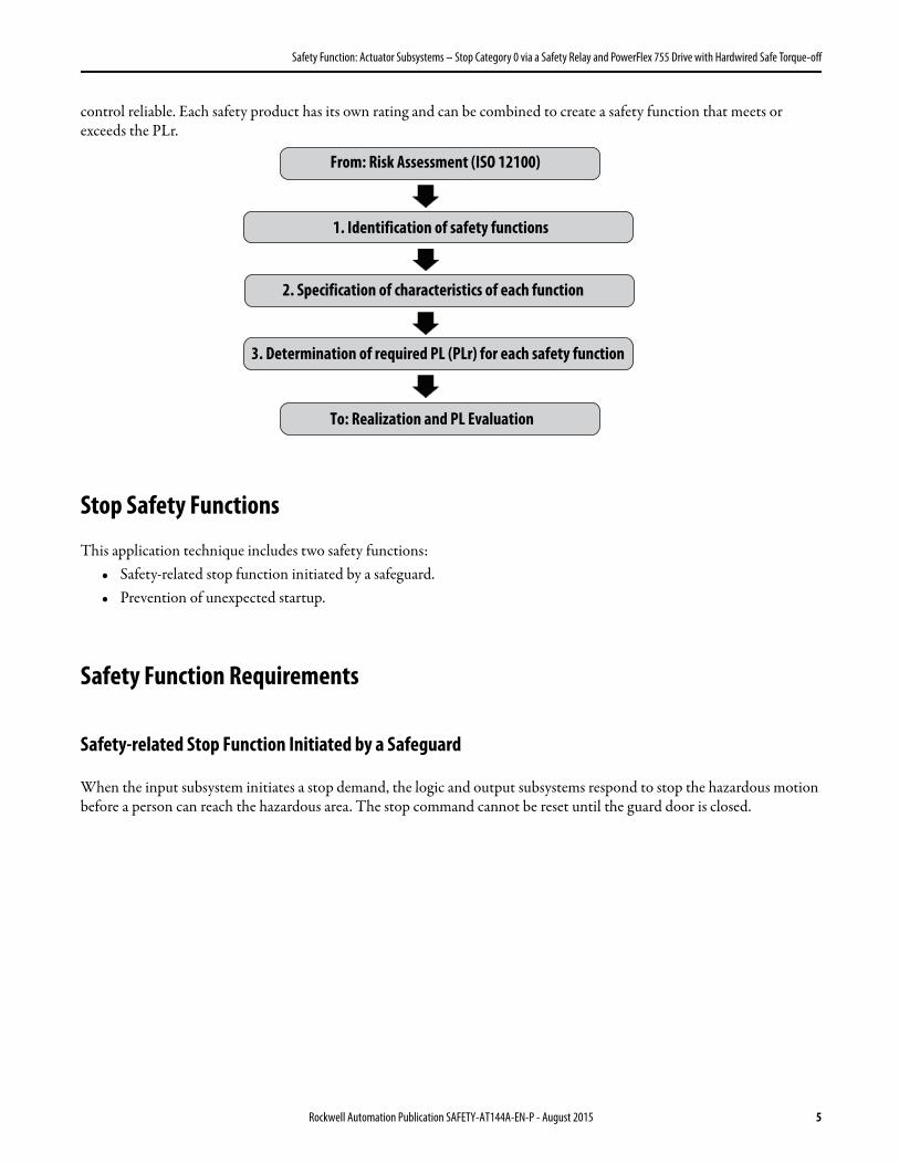
control reliable. Each safety product has its own rating and can be combined to create a safety function that meets or exceeds the PLr.
Stop Safety Functions
This application technique includes two safety functions:• Safety-related stop function initiated by a safeguard.• Prevention of unexpected startup.
Safety Function Requirements
Safety-related Stop Function Initiated by a Safeguard
When the input subsystem initiates a stop demand, the logic and output subsystems respond to stop the hazardous motion before a person can reach the hazardous area. The stop command cannot be reset until the guard door is closed.
From: Risk Assessment (ISO 12100)
1. Identification of safety functions
2. Specification of characteristics of each function
3. Determination of required PL (PLr) for each safety function
To: Realization and PL Evaluation
Rockwell Automation Publication SAFETY-AT144A-EN-P - August 2015 5

Safety Function: Actuator Subsystems – Stop Category 0 via a Safety Relay and PowerFlex 755 Drive with Hardwired Safe Torque-off
Prevention of an Unexpected Startup
The safety system cannot be reset, and hazardous motion cannot be restarted until the input subsystem is restored to the safe state. Once the guard door is closed and the logic subsystem is reset, a second action (pressing a Start button) is required before the hazardous motion can resume.
The safety functions in this application technique each meet or exceed the requirements for Category 3, Performance Level d (CAT. 3, PLd), per ISO 13849-1 and control reliable operation per ANSI B11.19.
Considerations for Safety Distance and Stopping Performance
Based on the selection of a sensor subsystem, the risk assessment determines if a safety distance calculation is required. Typically, a safety distance calculation is required if a non-separating sensor subsystem (such as a light curtain) is selected for the safety function. For moveable, separating-safeguard systems, the overall system- stopping performance must be calculated, measured, and compared to the calculated/measured access time.
When calculating a compliant safety distance for a non-separating safeguard system or the overall system-stopping performance of a separating safeguard system, see the safety relay installation instructions listed in the Additional Resources on page 14 for the necessary response-time data.
Functional Safety Description
The Guardmaster dual-input safety relay and PowerFlex 755 drive with safe torque-off (STO) use 1oo2 architecture to achieve the PFH value that is used in the PL calculation verification section of this document.
The Guardmaster dual-input safety relay monitors its safety inputs for valid status and faults. The relay monitors its internal circuitry for proper operation and faults, and it also monitors its safety output contacts for proper, valid status and faults. When the relay receives a safety demand on its inputs, or an invalid status or fault is detected, the relay reactivates its safety outputs immediately.
The PowerFlex 755 drive monitors its STO inputs for valid status and faults. The drive monitors its internal safety circuits for valid status and faults, and it also monitors its outputs for valid status and faults. When the Guardmaster dual-input safety relay de-energizes the drive STO inputs, the drive STO feature immediately forces the drive output power transistors to a disabled state. Likewise, the PowerFlex 755 drive forces the output power transistors to a disabled state immediately when a fault is detected, regardless of any stop characteristics configured for normal production stops. The hazardous motion controlled by the drive coasts to a stop. This feature does not provide electrical power isolation.
The system cannot be restarted until the input subsystem is restored to the safe state and the Guardmaster dual-input safety relay is reset. Once the relay is reset, the Start button can be pressed to start the hazardous motion. In this case, the Start button is connected directly to the drive as shown in the wiring diagram.
IMPORTANT The vendor must provide probability of failure per hour (PFH) and all relevant Functional Safety data for all the subsystems of this safety system necessary to prove that the overall safety functions meet the requirements for Performance Level d (PLd), per ISO 13849-1.
6 Rockwell Automation Publication SAFETY-AT144A-EN-P - August 2015
Safety Function: Actuator Subsystems – Stop Category 0 via a Safety Relay and PowerFlex 755 Drive with Hardwired Safe Torque-off
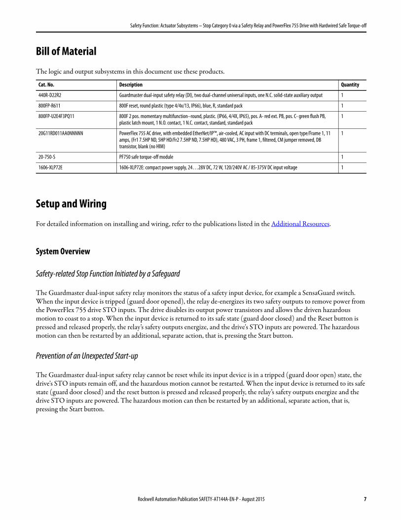
Bill of Material
The logic and output subsystems in this document use these products.
Setup and Wiring
For detailed information on installing and wiring, refer to the publications listed in the Additional Resources.
System Overview
Safety-related Stop Function Initiated by a Safeguard
The Guardmaster dual-input safety relay monitors the status of a safety input device, for example a SensaGuard switch. When the input device is tripped (guard door opened), the relay de-energizes its two safety outputs to remove power from the PowerFlex 755 drive STO inputs. The drive disables its output power transistors and allows the driven hazardous motion to coast to a stop. When the input device is returned to its safe state (guard door closed) and the Reset button is pressed and released properly, the relay’s safety outputs energize, and the drive's STO inputs are powered. The hazardous motion can then be restarted by an additional, separate action, that is, pressing the Start button.
Prevention of an Unexpected Start-up
The Guardmaster dual-input safety relay cannot be reset while its input device is in a tripped (guard door open) state, the drive's STO inputs remain off, and the hazardous motion cannot be restarted. When the input device is returned to its safe state (guard door closed) and the reset button is pressed and released properly, the relay’s safety outputs energize and the drive STO inputs are powered. The hazardous motion can then be restarted by an additional, separate action, that is, pressing the Start button.
Cat. No. Description Quantity
440R-D22R2 Guardmaster dual-input safety relay (DI), two dual-channel universal inputs, one N.C. solid-state auxiliary output 1
800FP-R611 800F reset, round plastic (type 4/4x/13, IP66), blue, R, standard pack 1
800FP-U2E4F3PQ11 800F 2 pos. momentary multifunction–round, plastic. (IP66, 4/4X, IP65), pos. A- red ext. PB, pos. C- green flush PB, plastic latch mount, 1 N.O. contact, 1 N.C. contact, standard, standard pack
1
20G11RD011AA0NNNNN PowerFlex 755 AC drive, with embedded EtherNet/IP™, air-cooled, AC input with DC terminals, open type/Frame 1, 11 amps, (Fr1 7.5HP ND, 5HP HD/Fr2 7.5HP ND, 7.5HP HD), 480 VAC, 3 PH, frame 1, filtered, CM jumper removed, DB transistor, blank (no HIM)
1
20-750-S PF750 safe torque-off module 1
1606-XLP72E 1606-XLP72E: compact power supply, 24…28V DC, 72 W, 120/240V AC / 85-375V DC input voltage 1
Rockwell Automation Publication SAFETY-AT144A-EN-P - August 2015 7
Safety Function: Actuator Subsystems – Stop Category 0 via a Safety Relay and PowerFlex 755 Drive with Hardwired Safe Torque-off
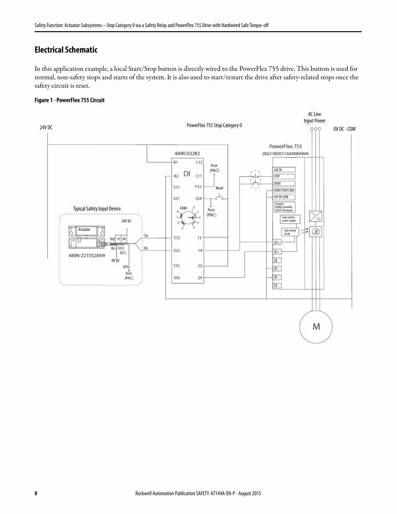
Electrical Schematic
In this application example, a local Start/Stop button is directly wired to the PowerFlex 755 drive. This button is used for normal, non-safety stops and starts of the system. It is also used to start/restart the drive after safety-related stops once the safety circuit is reset.
Figure 1 - PowerFlex 755 Circuit
AC Line Input Power
PowerFlex 755 Stop Category 0
Typical Safety Input Device
Actuator
24V DC
0V DC
Logic
Gate control power supply
Gate control circuit
24V DC
24V DC
STOP
START
START/STOP COM
24V DC COM
Jumpers:ENABLE InstalledSAFETY Removed
0V DC - COM
Reset
8 Rockwell Automation Publication SAFETY-AT144A-EN-P - August 2015
Safety Function: Actuator Subsystems – Stop Category 0 via a Safety Relay and PowerFlex 755 Drive with Hardwired Safe Torque-off
Configuration
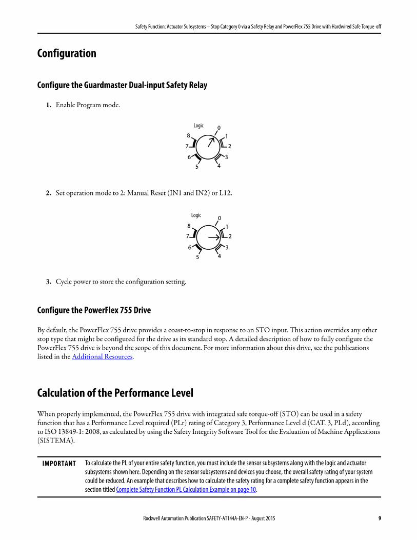
Configure the Guardmaster Dual-input Safety Relay
1. Enable Program mode.
2. Set operation mode to 2: Manual Reset (IN1 and IN2) or L12.
3. Cycle power to store the configuration setting.
Configure the PowerFlex 755 Drive
By default, the PowerFlex 755 drive provides a coast-to-stop in response to an STO input. This action overrides any other stop type that might be configured for the drive as its standard stop. A detailed description of how to fully configure the PowerFlex 755 drive is beyond the scope of this document. For more information about this drive, see the publications listed in the Additional Resources.
Calculation of the Performance Level
When properly implemented, the PowerFlex 755 drive with integrated safe torque-off (STO) can be used in a safety function that has a Performance Level required (PLr) rating of Category 3, Performance Level d (CAT. 3, PLd), according to ISO 13849-1: 2008, as calculated by using the Safety Integrity Software Tool for the Evaluation of Machine Applications (SISTEMA).
IMPORTANT To calculate the PL of your entire safety function, you must include the sensor subsystems along with the logic and actuator subsystems shown here. Depending on the sensor subsystems and devices you choose, the overall safety rating of your system could be reduced. An example that describes how to calculate the safety rating for a complete safety function appears in the section titled Complete Safety Function PL Calculation Example on page 10.
Logic
Logic
Rockwell Automation Publication SAFETY-AT144A-EN-P - August 2015 9
Safety Function: Actuator Subsystems – Stop Category 0 via a Safety Relay and PowerFlex 755 Drive with Hardwired Safe Torque-off
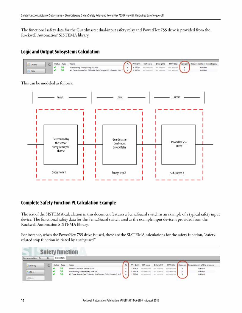
The functional safety data for the Guardmaster dual-input safety relay and PowerFlex 755 drive is provided from the Rockwell Automation® SISTEMA library.
Logic and Output Subsystems Calculation
This can be modeled as follows.
Complete Safety Function PL Calculation Example
The rest of the SISTEMA calculation in this document features a SensaGuard switch as an example of a typical safety input device. The functional safety data for the SensaGuard switch used as the example input device is provided from the Rockwell Automation SISTEMA library.
For instance, when the PowerFlex 755 drive is used, these are the SISTEMA calculations for the safety function, "Safety-related stop function initiated by a safeguard."
Output
Subsystem 1 Subsystem 2
Guardmaster Dual-Input
Safety RelayPowerFlex 755
Drive
LogicInput
Subsystem 3
Determined by the sensor
subsystems you choose
10 Rockwell Automation Publication SAFETY-AT144A-EN-P - August 2015
Safety Function: Actuator Subsystems – Stop Category 0 via a Safety Relay and PowerFlex 755 Drive with Hardwired Safe Torque-off
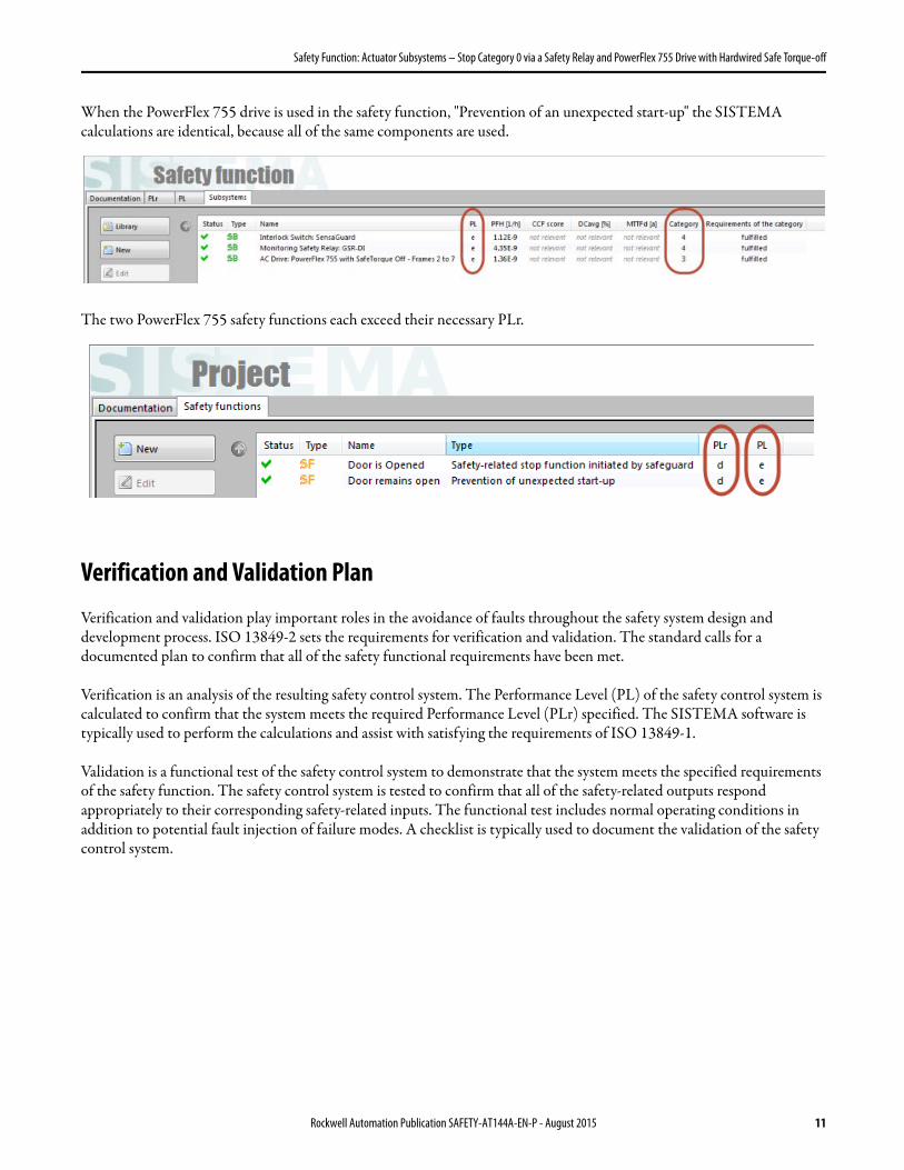
When the PowerFlex 755 drive is used in the safety function, "Prevention of an unexpected start-up" the SISTEMA calculations are identical, because all of the same components are used.
The two PowerFlex 755 safety functions each exceed their necessary PLr.
Verification and Validation Plan
Verification and validation play important roles in the avoidance of faults throughout the safety system design and development process. ISO 13849-2 sets the requirements for verification and validation. The standard calls for a documented plan to confirm that all of the safety functional requirements have been met.
Verification is an analysis of the resulting safety control system. The Performance Level (PL) of the safety control system is calculated to confirm that the system meets the required Performance Level (PLr) specified. The SISTEMA software is typically used to perform the calculations and assist with satisfying the requirements of ISO 13849-1.
Validation is a functional test of the safety control system to demonstrate that the system meets the specified requirements of the safety function. The safety control system is tested to confirm that all of the safety-related outputs respond appropriately to their corresponding safety-related inputs. The functional test includes normal operating conditions in addition to potential fault injection of failure modes. A checklist is typically used to document the validation of the safety control system.
Rockwell Automation Publication SAFETY-AT144A-EN-P - August 2015 11

Safety Function: Actuator Subsystems – Stop Category 0 via a Safety Relay and PowerFlex 755 Drive with Hardwired Safe Torque-off
Verification and Validation Checklist\
General Machinery Information
Machine Name/Model Number
Machine Serial Number
Customer Name
Test Date
Tester Name(s)
Schematic Drawing Number
Input Devices
Guardmaster Dual-input Safety Relay 440R-D22R2
Variable Frequency Drive 20G11RD011AA0NNNNN (PowerFlex 755)
Safety Wiring and Relay Configuration Verification
Test Step Verification Pass/Fail Changes/Modifications
1 Confirm that all components specifications are suitable for the application. Refer to Basic Safety Principles and Well-tried Safety Principles from ISO 13849-2.
2 Visually inspect the safety relay circuit to confirm that it is wired as documented in the schematics.
3 Confirm that the Guardmaster dual-input safety relay is set to the proper Logic configuration setting "2”.
Normal Operation Verification - The safety system responds properly to all normal Start, Stop, Reset, and sensor device inputs.
Test Step Verification Pass/Fail Changes/Modifications
1 Confirm that no one is in the guarded area.
2 Confirm that the hazardous motion is stopped.
3 Confirm that the door is closed.
4 Apply power to the safety system.
5 Confirm that the PWR/Fault, IN1 and IN2 status indicator LEDs of the Guardmaster dual-input safety relay are green. Confirm that the OUT status indicator blinks green.
6 Press and release the Reset button. Confirm that the Guardmaster dual-input safety relay OUT status indicator is now steady green.
7 Confirm that the hazardous motion does not start on powerup.
8 Press and release the external drive Start button. Confirm that the hazardous motion begins and the machine begins to operate.
9 Press the external Stop button. The machine must stop in its normal, configured manner. The safety system must not respond.
10 Press and release the external Start button. Confirm that the hazardous motion starts and the machine begins to operate.
11 Trip the input device. The safety system must trip. The hazardous motion must stop within the required time. Monitor the status indicators on the Guardmaster dual-input safety relay for proper operation. Only the PWR/Fault status indicator should be steady green. All other indicators should be OFF.
12 Press and release the Reset button. The Guardmaster dual-input safety relay must not respond.
13 Restore the input device to its safe state. The machine must not start. The IN1 and IN2 status indicators of the Guardmaster dual-input safety relay must be steady green. The OUT status indicator must blink green.
12 Rockwell Automation Publication SAFETY-AT144A-EN-P - August 2015

Safety Function: Actuator Subsystems – Stop Category 0 via a Safety Relay and PowerFlex 755 Drive with Hardwired Safe Torque-off
14 Press and release the Reset button. Confirm that the Guardmaster dual-input safety relay OUT status indicator is now steady green.
15 Press and release the external Start button. Confirm that the motor starts and the machine begins to operate.
Validation of Safe Response to Abnormal Operation - The safety system responds properly to all foreseeable faults with corresponding diagnostics.
Input Device - Guardmaster Dual-input Safety Relay Tests
Test Step Validation Pass/Fail Changes/Modifications
1 To find a safety function application technique that uses the type of input device you plan to use along with a Guardmaster dual input (or single input) safety relay, refer to:http://www.marketing.rockwellautomation.com/safety-solutions/en/MachineSafety/OurSafetySolutions/safety_functionsUse the input section of that validation procedure as a guide to test your input device.
Validation of Safe Response to Abnormal Operation - The safety system responds properly to all foreseeable faults with corresponding diagnostics.
Guardmaster Dual-input Safety Relay - PowerFlex 755 Drive Tests
Test Step Validation Pass/Fail Changes/Modifications
1 While the machine continues to run, remove the wire from terminal SP+ of the PowerFlex 755 drive. The hazardous motion must coast to a stop.The Guardmaster dual-input safety relay is not affected.
2 Replace the wire to terminal SP+. Press the drive Start button. The drive starts normally; the hazardous motion begins.
3 While the hazardous motion continues to run, jump 24V to terminal SP+ of the PowerFlex 755 drive. Trip the input device. The hazardous motion coasts to a stop. The Guardmaster dual-input safety relay behaves in the normal way to the input device being tripped.
4 Restore the input device to the safe state. Press and release the Reset button. The Guardmaster dual-input safety relay resets.
5 Remove the jumper. Press the drive Start button. The drive starts normally; the hazardous motion begins.
6 While the hazardous motion continues to run, jump 0V to terminal SP+ of the PowerFlex 755 drive. The hazardous motion coasts to a stop. The Guardmaster dual-input safety relay is not affected.
7 Remove the jumper. Press the drive Start button. The drive starts normally; the hazardous motion begins.
8 Repeat steps 1 through 7 using PowerFlex drive terminal SE+ in place of terminal SP+. The system responses must be the same as before.
IMPORTANT In addition to the verification and validation steps provided here, consult the application technique for your input subsystem for the steps required to validate the input device. Safety function application techniques are available at http://marketing.rockwellautomation.com/safety/en/safety_functions.
Rockwell Automation Publication SAFETY-AT144A-EN-P - August 2015 13
Safety Function: Actuator Subsystems – Stop Category 0 via a Safety Relay and PowerFlex 755 Drive with Hardwired Safe Torque-off
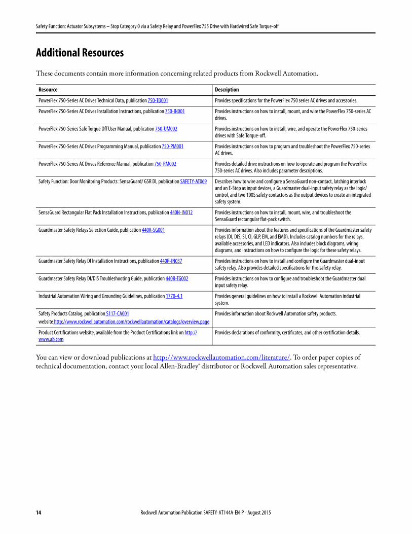
Additional Resources
These documents contain more information concerning related products from Rockwell Automation.
You can view or download publications at http://www.rockwellautomation.com/literature/. To order paper copies of technical documentation, contact your local Allen-Bradley® distributor or Rockwell Automation sales representative.
Resource Description
PowerFlex 750-Series AC Drives Technical Data, publication 750-TD001 Provides specifications for the PowerFlex 750 series AC drives and accessories.
PowerFlex 750-Series AC Drives Installation Instructions, publication 750-IN001 Provides instructions on how to install, mount, and wire the PowerFlex 750-series AC drives.
PowerFlex 750-Series Safe Torque Off User Manual, publication 750-UM002 Provides instructions on how to install, wire, and operate the PowerFlex 750-series drives with Safe Torque-off.
PowerFlex 750-Series AC Drives Programming Manual, publication 750-PM001 Provides instructions on how to program and troubleshoot the PowerFlex 750-series AC drives.
PowerFlex 750-Series AC Drives Reference Manual, publication 750-RM002 Provides detailed drive instructions on how to operate and program the PowerFlex 750-series AC drives. Also includes parameter descriptions.
Safety Function: Door Monitoring Products: SensaGuard/ GSR DI, publication SAFETY-AT069 Describes how to wire and configure a SensaGuard non-contact, latching interlock and an E-Stop as input devices, a Guardmaster dual-input safety relay as the logic/control, and two 100S safety contactors as the output devices to create an integrated safety system.
SensaGuard Rectangular Flat Pack Installation Instructions, publication 440N-IN012 Provides instructions on how to install, mount, wire, and troubleshoot the SensaGuard rectangular flat-pack switch.
Guardmaster Safety Relays Selection Guide, publication 440R-SG001 Provides information about the features and specifications of the Guardmaster safety relays (DI, DIS, SI, CI, GLP, EM, and EMD). Includes catalog numbers for the relays, available accessories, and LED indicators. Also includes block diagrams, wiring diagrams, and instructions on how to configure the logic for these safety relays.
Guardmaster Safety Relay DI Installation Instructions, publication 440R-IN037 Provides instructions on how to install and configure the Guardmaster dual-input safety relay. Also provides detailed specifications for this safety relay.
Guardmaster Safety Relay DI/DIS Troubleshooting Guide, publication 440R-TG002 Provides instructions on how to configure and troubleshoot the Guardmaster dual input safety relay.
Industrial Automation Wiring and Grounding Guidelines, publication 1770-4.1 Provides general guidelines on how to install a Rockwell Automation industrial system.
Safety Products Catalog, publication S117-CA001website http://www.rockwellautomation.com/rockwellautomation/catalogs/overview.page
Provides information about Rockwell Automation safety products.
Product Certifications website, available from the Product Certifications link on http://www.ab.com
Provides declarations of conformity, certificates, and other certification details.
14 Rockwell Automation Publication SAFETY-AT144A-EN-P - August 2015

Safety Function: Actuator Subsystems – Stop Category 0 via a Safety Relay and PowerFlex 755 Drive with Hardwired Safe Torque-off
Notes:
Rockwell Automation Publication SAFETY-AT144A-EN-P - August 2015 15
Allen-Bradley, Guardmaster, LISTEN. THINK. SOLVE, PowerFlex, Rockwell Automation, Rockwell Software, and SensaGuard are trademarks of Rockwell Automation, Inc.
Trademarks not belonging to Rockwell Automation are property of their respective companies.
EtherNet/IP is a trademark of ODVA, Inc.
Publication SAFETY-AT144A-EN-P - August 2015 Copyright © 2015 Rockwell Automation, Inc. All rights reserved. Printed in the U.S.A.
Documentation Feedback
Your comments will help us serve your documentation needs better. If you have any suggestions on how to improve this document, complete this form, publication RA-DU002, available at http://www.rockwellautomation.com/literature/.
Rockwell Otomasyon Ticaret A.Ş., Kar Plaza İş Merkezi E Blok Kat:6 34752 İçerenköy, İstanbul, Tel: +90 (216) 5698400
For more information onSafety Function Capabilities, visit:http://marketing.rockwellautomation.com/safety/en/safety_functions
Rockwell Automation maintains current product environmental information on its website athttp://www.rockwellautomation.com/rockwellautomation/about-us/sustainability-ethics/product-environmental-compliance.page.