Saferobot r10 En
108
1 of 106 KUKA.SafeRobot_1.0 03.05.03 en Controller KR C2 edition2005 KUKA.SafeRobot Release 1.0 for KUKA System Software (KSS) Release 5.4 Issued: 28 Sep 2005 Version: 03
Transcript of Saferobot r10 En

1 of 106KUKA.SafeRobot_1.0 03.05.03 en
Controller
KR C2 edition2005
KUKA.SafeRobot
Release 1.0
for KUKA System Software (KSS) Release 5.4
Issued: 28 Sep 2005 Version: 03
KUKA.SafeRobot
2 of 106 KUKA.SafeRobot_1.0 03.05.03 en
e Copyright 2005
KUKA Roboter GmbHThis documentation or excerpts therefrommay not be reproduced or disclosed to third parties without the express permission of the publishers.Other functions not described in this documentation may be operable in the controller. The user has no claims to these functions, however, inthe case of a replacement or service work.We have checked the content of this documentation for conformity with the hardware and software described. Nevertheless, discrepanciescannot be precluded, for which reason we are not able to guarantee total conformity. The information in this documentation is checked on aregular basis, however, and necessary corrections will be incorporated in subsequent editions.Subject to technical alterations without an effect on the function.

KUKA.SafeRobot_1.0 03.05.03 en 3 of 106
Contents
1 Introduction 7. . . . . . . . . . . . . . . . . . . . . . . . . . . . . . . . . . . . . . . . . . . . . . . . . . . . .
1.1 Target group for this documentation 7. . . . . . . . . . . . . . . . . . . . . . . . . . . . . . . . . . . . . . . . . . . . . .
1.2 Short description 7. . . . . . . . . . . . . . . . . . . . . . . . . . . . . . . . . . . . . . . . . . . . . . . . . . . . . . . . . . . . . . .
1.3 Conditions, instructions, restrictions 8. . . . . . . . . . . . . . . . . . . . . . . . . . . . . . . . . . . . . . . . . . . . . .1.3.1 Robot hardware 8. . . . . . . . . . . . . . . . . . . . . . . . . . . . . . . . . . . . . . . . . . . . . . . . . . . . . . . . . . . . . . .1.3.2 Controller hardware 8. . . . . . . . . . . . . . . . . . . . . . . . . . . . . . . . . . . . . . . . . . . . . . . . . . . . . . . . . . . .1.3.3 System software 8. . . . . . . . . . . . . . . . . . . . . . . . . . . . . . . . . . . . . . . . . . . . . . . . . . . . . . . . . . . . . . .1.3.4 Restrictions 9. . . . . . . . . . . . . . . . . . . . . . . . . . . . . . . . . . . . . . . . . . . . . . . . . . . . . . . . . . . . . . . . . . .
1.4 Terms and abbreviations used 9. . . . . . . . . . . . . . . . . . . . . . . . . . . . . . . . . . . . . . . . . . . . . . . . . . .
1.5 Service 10. . . . . . . . . . . . . . . . . . . . . . . . . . . . . . . . . . . . . . . . . . . . . . . . . . . . . . . . . . . . . . . . . . . . . . .
2 Safety 11. . . . . . . . . . . . . . . . . . . . . . . . . . . . . . . . . . . . . . . . . . . . . . . . . . . . . . . . . . .
2.1 Symbols and icons 11. . . . . . . . . . . . . . . . . . . . . . . . . . . . . . . . . . . . . . . . . . . . . . . . . . . . . . . . . . . . .2.1.1 Safety symbols 11. . . . . . . . . . . . . . . . . . . . . . . . . . . . . . . . . . . . . . . . . . . . . . . . . . . . . . . . . . . . . . . .2.1.2 Icons 11. . . . . . . . . . . . . . . . . . . . . . . . . . . . . . . . . . . . . . . . . . . . . . . . . . . . . . . . . . . . . . . . . . . . . . . . .
2.2 General information 12. . . . . . . . . . . . . . . . . . . . . . . . . . . . . . . . . . . . . . . . . . . . . . . . . . . . . . . . . . . .
2.3 Additional safety instructions for “KUKA.SafeRobot” 12. . . . . . . . . . . . . . . . . . . . . . . . . . . . . . . .
2.4 Designated use 13. . . . . . . . . . . . . . . . . . . . . . . . . . . . . . . . . . . . . . . . . . . . . . . . . . . . . . . . . . . . . . . .
2.5 Liability 13. . . . . . . . . . . . . . . . . . . . . . . . . . . . . . . . . . . . . . . . . . . . . . . . . . . . . . . . . . . . . . . . . . . . . . .
3 Product description 15. . . . . . . . . . . . . . . . . . . . . . . . . . . . . . . . . . . . . . . . . . . . . .
3.1 General 15. . . . . . . . . . . . . . . . . . . . . . . . . . . . . . . . . . . . . . . . . . . . . . . . . . . . . . . . . . . . . . . . . . . . . . .3.1.1 Ranges 15. . . . . . . . . . . . . . . . . . . . . . . . . . . . . . . . . . . . . . . . . . . . . . . . . . . . . . . . . . . . . . . . . . . . . . .3.1.2 Configuration of the ranges 16. . . . . . . . . . . . . . . . . . . . . . . . . . . . . . . . . . . . . . . . . . . . . . . . . . . . . .3.1.3 Braking reactions 16. . . . . . . . . . . . . . . . . . . . . . . . . . . . . . . . . . . . . . . . . . . . . . . . . . . . . . . . . . . . . .3.1.4 Braking distance of the robot mechanical system (stopping distance) 17. . . . . . . . . . . . . . . . .
3.2 Functions 18. . . . . . . . . . . . . . . . . . . . . . . . . . . . . . . . . . . . . . . . . . . . . . . . . . . . . . . . . . . . . . . . . . . . .3.2.1 Safe functions 18. . . . . . . . . . . . . . . . . . . . . . . . . . . . . . . . . . . . . . . . . . . . . . . . . . . . . . . . . . . . . . . . .3.2.2 Conditions for the safe monitoring of the robot 18. . . . . . . . . . . . . . . . . . . . . . . . . . . . . . . . . . . . .3.2.3 Monitoring of the safe inputs and outputs 18. . . . . . . . . . . . . . . . . . . . . . . . . . . . . . . . . . . . . . . . . .3.2.4 Safe reduced velocity, axis--specific 19. . . . . . . . . . . . . . . . . . . . . . . . . . . . . . . . . . . . . . . . . . . . . .3.2.5 Safe reduced velocity, Cartesian 19. . . . . . . . . . . . . . . . . . . . . . . . . . . . . . . . . . . . . . . . . . . . . . . . .3.2.6 Safe position sensing system 19. . . . . . . . . . . . . . . . . . . . . . . . . . . . . . . . . . . . . . . . . . . . . . . . . . . .3.2.7 Safe axis range monitoring 20. . . . . . . . . . . . . . . . . . . . . . . . . . . . . . . . . . . . . . . . . . . . . . . . . . . . . .3.2.8 Safe operational stop 23. . . . . . . . . . . . . . . . . . . . . . . . . . . . . . . . . . . . . . . . . . . . . . . . . . . . . . . . . . .
3.3 Configuration program 23. . . . . . . . . . . . . . . . . . . . . . . . . . . . . . . . . . . . . . . . . . . . . . . . . . . . . . . . . .
4 Layout, interfaces 25. . . . . . . . . . . . . . . . . . . . . . . . . . . . . . . . . . . . . . . . . . . . . . . .
4.1 Layout of robot and control cabinet 25. . . . . . . . . . . . . . . . . . . . . . . . . . . . . . . . . . . . . . . . . . . . . . .4.1.1 Junction boxes on the robot 26. . . . . . . . . . . . . . . . . . . . . . . . . . . . . . . . . . . . . . . . . . . . . . . . . . . . .4.1.2 Control cabinet KR C2 edition2005 27. . . . . . . . . . . . . . . . . . . . . . . . . . . . . . . . . . . . . . . . . . . . . . .4.1.3 Connection panel on the control cabinet (standard) 28. . . . . . . . . . . . . . . . . . . . . . . . . . . . . . . . .
4 of 106 KUKA.SafeRobot_1.0 03.05.03 en
4.1.4 Connection panel on the control cabinet (DaimlerChrysler) 29. . . . . . . . . . . . . . . . . . . . . . . . . . .
4.2 SafeRobot control cabinet components 30. . . . . . . . . . . . . . . . . . . . . . . . . . . . . . . . . . . . . . . . . . .4.2.1 Multi--function card MFC 3 Tech 30. . . . . . . . . . . . . . . . . . . . . . . . . . . . . . . . . . . . . . . . . . . . . . . . . .4.2.2 Safety logic -- CI 3 technology 33. . . . . . . . . . . . . . . . . . . . . . . . . . . . . . . . . . . . . . . . . . . . . . . . . . .4.2.3 Safe RDC 36. . . . . . . . . . . . . . . . . . . . . . . . . . . . . . . . . . . . . . . . . . . . . . . . . . . . . . . . . . . . . . . . . . . . .4.2.4 Interfaces to the Safe RDC 45. . . . . . . . . . . . . . . . . . . . . . . . . . . . . . . . . . . . . . . . . . . . . . . . . . . . . .
4.3 Connecting cables between robot and control cabinet 54. . . . . . . . . . . . . . . . . . . . . . . . . . . . . . .4.3.1 Connecting cables diagram 54. . . . . . . . . . . . . . . . . . . . . . . . . . . . . . . . . . . . . . . . . . . . . . . . . . . . . .4.3.2 Connecting cables 55. . . . . . . . . . . . . . . . . . . . . . . . . . . . . . . . . . . . . . . . . . . . . . . . . . . . . . . . . . . . .4.3.3 Configuration of the connecting cables 56. . . . . . . . . . . . . . . . . . . . . . . . . . . . . . . . . . . . . . . . . . . .4.3.4 Interface assignments 57. . . . . . . . . . . . . . . . . . . . . . . . . . . . . . . . . . . . . . . . . . . . . . . . . . . . . . . . . .
4.4 Reference switch 58. . . . . . . . . . . . . . . . . . . . . . . . . . . . . . . . . . . . . . . . . . . . . . . . . . . . . . . . . . . . . .4.4.1 Components for reference switch 60. . . . . . . . . . . . . . . . . . . . . . . . . . . . . . . . . . . . . . . . . . . . . . . .4.4.2 Installing the reference switch 62. . . . . . . . . . . . . . . . . . . . . . . . . . . . . . . . . . . . . . . . . . . . . . . . . . .
4.5 Keyswitch for “safe retraction” mode 64. . . . . . . . . . . . . . . . . . . . . . . . . . . . . . . . . . . . . . . . . . . . . .
4.6 Periphery 64. . . . . . . . . . . . . . . . . . . . . . . . . . . . . . . . . . . . . . . . . . . . . . . . . . . . . . . . . . . . . . . . . . . . .4.6.1 Example of connection to a safety PLC (Siemens ET200S) 64. . . . . . . . . . . . . . . . . . . . . . . . . .
4.7 Assignment of X40 for operation without a PLC 67. . . . . . . . . . . . . . . . . . . . . . . . . . . . . . . . . . . .
4.8 Functional examples 68. . . . . . . . . . . . . . . . . . . . . . . . . . . . . . . . . . . . . . . . . . . . . . . . . . . . . . . . . . .4.8.1 Example of a loading station at a turntable 69. . . . . . . . . . . . . . . . . . . . . . . . . . . . . . . . . . . . . . . .4.8.2 Example of a loading station at a robot gripper 71. . . . . . . . . . . . . . . . . . . . . . . . . . . . . . . . . . . . .
5 Commissioning 73. . . . . . . . . . . . . . . . . . . . . . . . . . . . . . . . . . . . . . . . . . . . . . . . . .
5.1 Prerequisites 73. . . . . . . . . . . . . . . . . . . . . . . . . . . . . . . . . . . . . . . . . . . . . . . . . . . . . . . . . . . . . . . . . .5.1.1 Requirements regarding the operating personnel 73. . . . . . . . . . . . . . . . . . . . . . . . . . . . . . . . . . .5.1.2 Instruction and training of operating personnel 73. . . . . . . . . . . . . . . . . . . . . . . . . . . . . . . . . . . . .5.1.3 Training for administrators and safety maintenance personnel 73. . . . . . . . . . . . . . . . . . . . . . . .
5.2 Installing the configuration program 74. . . . . . . . . . . . . . . . . . . . . . . . . . . . . . . . . . . . . . . . . . . . . . .
5.3 Using the configuration program 74. . . . . . . . . . . . . . . . . . . . . . . . . . . . . . . . . . . . . . . . . . . . . . . . .5.3.1 User group 74. . . . . . . . . . . . . . . . . . . . . . . . . . . . . . . . . . . . . . . . . . . . . . . . . . . . . . . . . . . . . . . . . . . .5.3.2 Starting the configuration program 75. . . . . . . . . . . . . . . . . . . . . . . . . . . . . . . . . . . . . . . . . . . . . . . .5.3.3 Checking the data 76. . . . . . . . . . . . . . . . . . . . . . . . . . . . . . . . . . . . . . . . . . . . . . . . . . . . . . . . . . . . . .5.3.4 Changing parameter values 77. . . . . . . . . . . . . . . . . . . . . . . . . . . . . . . . . . . . . . . . . . . . . . . . . . . . .5.3.5 Configuration of safety--relevant parameters 78. . . . . . . . . . . . . . . . . . . . . . . . . . . . . . . . . . . . . . .5.3.6 Parameter default values 84. . . . . . . . . . . . . . . . . . . . . . . . . . . . . . . . . . . . . . . . . . . . . . . . . . . . . . .
5.4 Brake test and reference run 86. . . . . . . . . . . . . . . . . . . . . . . . . . . . . . . . . . . . . . . . . . . . . . . . . . . .5.4.1 Brake test 86. . . . . . . . . . . . . . . . . . . . . . . . . . . . . . . . . . . . . . . . . . . . . . . . . . . . . . . . . . . . . . . . . . . . .5.4.2 Reference run 87. . . . . . . . . . . . . . . . . . . . . . . . . . . . . . . . . . . . . . . . . . . . . . . . . . . . . . . . . . . . . . . . .
5.5 Acceptance test for KUKA.SafeRobot -- Checklist 88. . . . . . . . . . . . . . . . . . . . . . . . . . . . . . . . . .
6 Operation 89. . . . . . . . . . . . . . . . . . . . . . . . . . . . . . . . . . . . . . . . . . . . . . . . . . . . . . .
6.1 Safe robot retraction 89. . . . . . . . . . . . . . . . . . . . . . . . . . . . . . . . . . . . . . . . . . . . . . . . . . . . . . . . . . . .
7 Programming 91. . . . . . . . . . . . . . . . . . . . . . . . . . . . . . . . . . . . . . . . . . . . . . . . . . . .
7.1 Brake test and reference run 91. . . . . . . . . . . . . . . . . . . . . . . . . . . . . . . . . . . . . . . . . . . . . . . . . . . .7.1.1 Example of extension to “SPS.SUB” 92. . . . . . . . . . . . . . . . . . . . . . . . . . . . . . . . . . . . . . . . . . . . . .7.1.2 Example of extension to a KRL program 93. . . . . . . . . . . . . . . . . . . . . . . . . . . . . . . . . . . . . . . . . .
KUKA.SafeRobot_1.0 03.05.03 en 5 of 106
8 Diagnostics, fault analysis 95. . . . . . . . . . . . . . . . . . . . . . . . . . . . . . . . . . . . . . . .
8.1 Error messages for KUKA.SafeRobot 95. . . . . . . . . . . . . . . . . . . . . . . . . . . . . . . . . . . . . . . . . . . . .
9 Repair 97. . . . . . . . . . . . . . . . . . . . . . . . . . . . . . . . . . . . . . . . . . . . . . . . . . . . . . . . . . .
9.1 Preparation 97. . . . . . . . . . . . . . . . . . . . . . . . . . . . . . . . . . . . . . . . . . . . . . . . . . . . . . . . . . . . . . . . . . .
9.2 Removing the Safe RDC 98. . . . . . . . . . . . . . . . . . . . . . . . . . . . . . . . . . . . . . . . . . . . . . . . . . . . . . . .
9.3 Installing the Safe RDC 99. . . . . . . . . . . . . . . . . . . . . . . . . . . . . . . . . . . . . . . . . . . . . . . . . . . . . . . . .
10 Appendix 101. . . . . . . . . . . . . . . . . . . . . . . . . . . . . . . . . . . . . . . . . . . . . . . . . . . . . . . .
10.1 Technical data 101. . . . . . . . . . . . . . . . . . . . . . . . . . . . . . . . . . . . . . . . . . . . . . . . . . . . . . . . . . . . . . . . .
10.2 Acceptance test for KUKA.SafeRobot -- Checklists 103. . . . . . . . . . . . . . . . . . . . . . . . . . . . . . . . .

6 of 106 KUKA.SafeRobot_1.0 03.05.03 en
KUKA.SafeRobot_1.0 03.05.03 en 7 of 106
1 Introduction
1.1 Target group for this documentation
This user manual is intended for use by the system integrator.
InfoInformation about KUKA training programs is available from www.kuka.com or fromyour KUKA Roboter GmbH representative.
1.2 Short description
“KUKA.SafeRobot” -- based on the controller KR C2 with ESC safety logic -- is anautomatically controlled programmable robot system for use in automated productionsystems.
“KUKA.SafeRobot” features safe hardware and software and allows the position of the robotto be continuously monitored. The principle of the safe functions is based on safemonitoringof limit values.
If the robot moves outside the permitted ranges the Electronic Safety Circuit (ESC) safetysystem disconnects the drives.
A basic description of the individual functions of the “KUKA.SafeRobot” technology iscontained in Chapter 3 of this documentation. Chapter 4 describes the individualcomponents of “KUKA.SafeRobot”, its layout and interfaces.
Commissioning is described in Chapter 4. In this chapter the installation of the configurationprogram and its operation are also described.
Information on operation can be found in Chapter 6.
Chapter 7 contains information on programming and program examples for extended KRLprograms, brake tests and reference runs, as well as the extended “SPS.SUB”.
The “KUKA.SafeRobot” error messages are described in Chapter 8.
Chapter 9 describes the removal and installation of the Safe RDC.
Chapter 10 contains a summary of the technical data and the checklists for the acceptancetest of “KUKA.SafeRobot”.
“KUKA.SafeRobot” satisfies category 3 to EN 954--1, and SIL 2 to EN 61508, and hasbeen approved by the German Technical Inspectorate (TÜV).

8 of 106 KUKA.SafeRobot_1.0 03.05.03 en
1.3 Conditions, instructions, restrictions
1.3.1 Robot hardware
“KUKA.SafeRobot” can be used with all KUKA robot variants in the following list:
Low payloads
KR 6; KR 6 KS; KR 6 ARC;KR 16; KR 16 CR; KR 16 EX; KR 16 KS; KR 16 L6; KR 16 L6 ARC; KR 16 L6 KS
Medium payloads
KR 30--3; KR30--3 KS; KR 30 HA; KR 30 L16;KR 60--3; KR 60--3 KS; KR 60 HA
High payloads
KR 100 comp, KR 140 comp, KR 200 comp;KR 150--2; KR; KR 150--2 K; KR 150 W; KR 180--2; KR 180--2 K; KR 180 L130--2 CR;KR 210--2; KR 210--2 K; KR240--2
Heavy--duty robots
KR 360; KR 500
1.3.2 Controller hardware
The following are necessary for “KUKA.SafeRobot”:
G Robot controller KR C2 edition2005 with KPC 2004
G ESC CI 3 Tech
G MFC3 Tech and
G KCP2 standard edition2005 with brought--out operating modes T1 and T2.
G Safe RDC
G DSE--IBS C33
G Reference switch with actuating plate
1.3.3 System software
KUKA System Software (KSS) Release 5.4.
KUKA.SafeRobot_1.0 03.05.03 en 9 of 106
1.3.4 Restrictions
NoteMaster/slave axes and CR (RoboTeam) are not supported..The functions of “KUKA.SafeRobot” do not replace the limit switches and mechanicalend stops for range limitation of robot axes A1, A2 and A3.
Because of the design and quality assurance the robot mechanical parts operate safely.The probability of malfunctions is very slight, nevertheless there remains a smallresidual risk.
Therefore even in ranges which are safeguarded only by the control technology of therobot, cognizance must be taken of possible incorrect movements by the robot.
1.4 Terms and abbreviations used
The following terms and abbreviations are used in this documentation:
Working range Permissible range within which the robot can work and move;all the robot axes are contained within this range
Process range Permissible range within which the robot may move
Safety range Non--permissible range within which the robot may neither worknor move
Axis range 1 Continuously monitored axis range
Axis ranges 2 ... 7 Monitoring using safe inputs
Axis ranges 8 ... 10 Status reporting using safe outputs
Reduced Permissible range within which the robot may move but only atvelocity range reduced velocity
I/O Inputs / Outputs
KR C2 edition2005 Control cabinet for KUKA robots
KCP2 Standard KUKA Control Panel -- Teach pendant with extended functionalityedition2005 for KUKA.SafeRobot
HMI Human Machine Interface
KRL KUKA Robot Language
10 of 106 KUKA.SafeRobot_1.0 03.05.03 en
KUKA.SafeRobot Controller variant with software--controlled axis disconnection
Safe RDC Circuit board for the Resolver Digital Converter with safemonitoring
Safe RDC Box Housing for the Safe RDC (in the robot base)
I/O Print Piggyback circuit board on the Safe RDC
ESC Electronic Safety Circuit -- safety logic of the controller
ENA Externer NOT--AUS -- ESC input triggering a category 1EMERGENCY STOP
QE Local STOP -- ESC input triggering a category 0EMERGENCY STOP
MFC 3 Tech Multi Function Card -- plug--in card in the PC
CI 3 Technology Safety bus for monitoring safety--relevant components.
DSE--IBS Digital Servo Electronics -- piggyback circuit board on theMFC 3 Tech
KGD KUKA Guiding Device -- unit for manual movement of axes
EMT Electronic Measuring Tool
Meas “Fast Measurement” input
DSP Digital Signal Processor
SSI Standard Serial Interface
PLC Programmable Logic Controller (within customer’s system)
CR Cooperating Robots (RoboTeam, Option)
1.5 Service
Procedure for dealing with queries or problems
If any questions or problems arise while using the robot system, please first try to solve themwith the aid of these operating instructions.
Should this not bring about the desired result, please contact one of our Service Centers.So that the situation can be resolved easily and quickly, it is advisable for you to be at therobot with access to the control panel when you call.
The operating handbook [KR C2edition2005 / Introduction / Service] will tell you whatinformation is important and which service support point you should contact.
KUKA.SafeRobot_1.0 03.05.03 en 11 of 106
2 Safety
2.1 Symbols and icons
The following safety symbols and pictograms are used in these operating instructions:
2.1.1 Safety symbols
Text passages indicated by the following safety symbols are relevant to safety and must beobserved.
WARNING!Following these safety warnings carefully can prevent personal injury.
CAUTION!Following these safety warnings carefully can prevent material damage.
2.1.2 Icons
NOTEIndicates special features for particular attention.
InfoIndicates passages which are of particular significance or are useful for greaterunderstanding.
See alsoIndicates sections or chapters containing further information and explanations.
12 of 106 KUKA.SafeRobot_1.0 03.05.03 en
2.2 General information
G All pertinent safety regulations as well as the booklet [Safety and InstallationInstructions] are to be observed when working on the system.
G The KUKA safety chapter [KR CSafety, General] is suppliedwith the robot system andmust be read and understood before commencing work.
G The safety instructions in the KR C2 Operating Handbook must be observed.
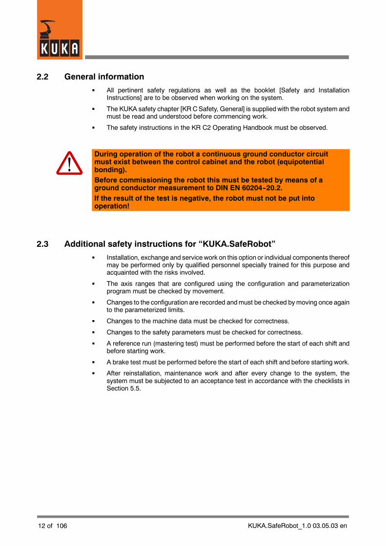
During operation of the robot a continuous ground conductor circuitmust exist between the control cabinet and the robot (equipotentialbonding).Before commissioning the robot this must be tested by means of aground conductor measurement to DIN EN 60204--20.2.If the result of the test is negative, the robot must not be put intooperation!
2.3 Additional safety instructions for “KUKA.SafeRobot”
G Installation, exchange and service work on this option or individual components thereofmay be performed only by qualified personnel specially trained for this purpose andacquainted with the risks involved.
G The axis ranges that are configured using the configuration and parameterizationprogram must be checked by movement.
G Changes to the configuration are recorded andmust be checked bymoving once againto the parameterized limits.
G Changes to the machine data must be checked for correctness.
G Changes to the safety parameters must be checked for correctness.
G A reference run (mastering test) must be performed before the start of each shift andbefore starting work.
G A brake test must be performed before the start of each shift and before starting work.
G After reinstallation, maintenance work and after every change to the system, thesystem must be subjected to an acceptance test in accordance with the checklists inSection 5.5.

KUKA.SafeRobot_1.0 03.05.03 en 13 of 106
2.4 Designated use
“KUKA.SafeRobot” is intended exclusively for use in accordance with the propertiesdescribed in this documentation.
Using the system for any other or additional purpose is considered contrary to its designateduse. The manufacturer cannot be held liable for any damage resulting from such use. Therisk lies entirely with the user.
In addition the regulations and instructions contained in theKRCusermanual, chapter [KR CSafety, General], section [Designated Use] must be complied with.
“KUKA.SafeRobot” must be used only in conjunction with an effective safeguard (safetyfence, light barrier etc.).
The applicable national laws, regulations, standards and guidelines must be observed andcomplied with.
“KUKA.SafeRobot” can be used in conjunction with all KUKA applications for which it isapproved. Examples of KUKA applications are:
G Welding
G Assembly
G Handling
G Coating
G Measuring/inspection
G Machining
2.5 Liability
“KUKA.SafeRobot” has been designed, built, and programmed using state--of--the--arttechnology and in accordance with the recognized safety rules. Nevertheless, improperinstallation of this system or its employment for a purpose other than the intended one mayconstitute a risk to life and limb of operating personnel or of third parties, or cause damageto or failure of the control cabinet, resulting in damage to or failure of the entire robot systemand other material property.
“KUKA.SafeRobot” may only be used in technically fault--free condition in accordance withits designated use and only by safety--conscious persons who are fully aware of the risksinvolved in its operation. Connection and use must be carried out in compliance with thisdocumentation.

14 of 106 KUKA.SafeRobot_1.0 03.05.03 en

KUKA.SafeRobot_1.0 03.05.03 en 15 of 106
3 Product description
3.1 General
The “KUKA.SafeRobot” technology permits continuous safe monitoring of the movementlimits of a robot.
In contrast to mechanical--electrical technology for working range monitoring usingmechanical limit switches on the axis ranges, “KUKA.SafeRobot” evaluates signals obtainedfrom the resolvers on the motor shafts. This permits quick reaction times.
“KUKA.SafeRobot” permits not only the monitoring of the main axes (A1 ... A3) but also themonitoring of the wrist axes (A4 ... A6).
“KUKA.SafeRobot” features safe hardware and software--based functions and allows theposition of the robot to be continuously monitored, with safe axis disconnection.
3.1.1 Ranges
1 Working range2 Safety range
Fig. 1 Working range, safety range
“KUKA.SafeRobot” allows working ranges and safety ranges to be defined for the robot.These ranges are shown schematically in Fig. 1.
16 of 106 KUKA.SafeRobot_1.0 03.05.03 en
Definition of the ranges
G Working range All the robot axes are contained within this range
G Safety range No axes may be in this range
The monitoring of the ranges is performed by “KUKA.SafeRobot” using redundantlysafeguarded position monitoring with detection of the respective axis positions. The axisranges can thus easily be restricted and the safeguarded working ranges defined.
3.1.2 Configuration of the ranges
The configuration of the ranges is performed using the “KUKA.SafeRobot” configurationprogram. Detailed information on this can be found in Section 5.3 of this documentation.
3.1.3 Braking reactions
Two types of STOP are defined as braking reactions in the event of an error or the violationof configured settings:
G STOP 0:If, at the point in time when the robot moves into a non--permissible range, themonitoring of this range is active, the robot will be stopped with a category 0 stop(STOP 0). To trigger a STOP 0 the ESC signal “QE” is set to LOW via a safe output ofthe Safe RDC. This leads to direct disconnection of the drives.
G STOP 1:If, at the point in time when monitoring is activated, the robot is already within anon--permissible range, the robot will be stopped with a category 1 stop (STOP 1).To trigger a STOP 1 the ESC signal “ENA” is set to LOW via a safe output of the SafeRDC. This leads to delayed disconnection of the drives.

KUKA.SafeRobot_1.0 03.05.03 en 17 of 106
3.1.4 Braking distance of the robot mechanical system (stopping distance)
When the robot is stopped due to triggering of a monitoring function, the drives aredisconnected and the brakes are applied. Due to the mass inertia and other influences, therobot has a certain stopping distance.
30° 30°
5 0°
1 2 3 4
1 Safety range without stopping distances 4 Actual working range
2 Actual safety range 5 Robot
3 Braking distance (max. stopping distance)
Fig. 2 Working range, safety range, braking distance
Fig. 2 shows schematically the stopping distance (braking ramp), when the robot is stopped.The extent of the controlled braking ramp, and thus the actual braking distance, depends onthe direction of the path and the kinetic energy of the robot at the time of disconnection.
The braking distance of the robot at maximum velocity is approx. 30°. The exact value canonly be determined by measuring the stopping distance.

18 of 106 KUKA.SafeRobot_1.0 03.05.03 en
3.2 Functions
3.2.1 Safe functions
The safe functions include:
G Safe reduced velocity/acceleration (axis--specific)
G Safe reduced velocity (Cartesian) at the flange
G Safe position sensing system
G Safe axis range monitoring
G Safe operational stop
G Safe stop (ESC function)
G Monitoring of the robot mastering
G Brake test
G Safe disconnection of drives in accordance with “STOP 0” or “STOP 1”
3.2.2 Conditions for the safe monitoring of the robot
The following conditions must be satisfied for the safe monitoring of the robot:
G The safety parameters have been confirmed in the configuration program (seeChapter 7 of this documentation).
G TheKUKA.SafeRobot acceptance test has beenperformedsuccessfully inaccordancewith the checklists (see Section 5.5 of this documentation).
Exceptions to this are the braking test (see Section 5.4.1) and the reference run (seeSection 5.4.2).
3.2.3 Monitoring of the safe inputs and outputs
To ensure the safety of the digital inputs and outputs of the Safe RDC, their functions arechecked cyclically during operation.
This entails monitoring of the
G inputs for cross--connections and dual--channel operation
and the
G outputs for cross--connections, short circuits and cable breaks
In the event of a fault, the robot will be stopped (STOP 0) and a message displayed.
KUKA.SafeRobot_1.0 03.05.03 en 19 of 106
3.2.4 Safe reduced velocity, axis--specific
This monitoring function “safe reduced velocity, axis--specific” is activated by a safe input on theSafeRDC. This causes limit values and actual values to be compared for every axis by the SafeRDC. If the actual velocity exceeds the limit value, the drives are disconnected (STOP 0).
Monitoring is active under the following conditions:
-- Operating mode T1 (Test 1)
-- Safe robot retraction activated
-- Safe operational stop activated
-- dV signal LOW activated
In the operating mode “Automatic” the monitoring of the safe reduced velocity is activatedby an input “dV” to the Safe RDC.
3.2.5 Safe reduced velocity, Cartesian
The monitoring function “safe reduced velocity, Cartesian” to EN 775 relates to the flangecenter point and is used for monitoring the safe reduced velocity.
The Safe RDC calculates the respective Cartesian position and velocity of the flange, basedon the resolver data. The velocity is monitored using a limit value configured with the aid ofthe configuration program.
Monitoring is active under the following conditions:
-- Operating mode T1 (Test 1)
-- Safe robot retraction activated
-- Safe operational stop activated
-- dV signal LOW activated
3.2.6 Safe position sensing system
The safe position sensing system operates via a dual--channel link to the Safe RDC.
The software checks the reported values for plausibility. If deviations are found, the robot willbe stopped (STOP 0).

20 of 106 KUKA.SafeRobot_1.0 03.05.03 en
3.2.7 Safe axis range monitoring
A total of 10 axis ranges are available for the function “safe axis rangemonitoring”. Eachaxisrange can be defined as a working range or safety range.
If aworkingor safety range is violateda correspondingmessagewill be displayed. If the robotmoves back into the permissible range, a corresponding acknowledgement message will bedisplayed.
The respective axis range is deactivated if a High signal is present at the input. Afterdisconnection, the robot can only be moved into the permissible range in “safe retraction”mode.
The axis ranges are divided into three groups:
G Axis range 1 Continuously monitored
G Axis ranges 2 ... 7 Monitoring using safe inputs
G Axis ranges 8 ... 10 Status reporting using safe outputs
Axis range 1
Axis range 1 is continuously monitored. If the configured axis range is exceeded the drivesare disconnected and a category 0 stop performed (STOP 0).
QE (ESC)
STOP 0
Axis range 1
Axis 1Axis 2Axis 3
...Axis 8
Fig. 3 Axis range 1
KUKA.SafeRobot_1.0 03.05.03 en 21 of 106
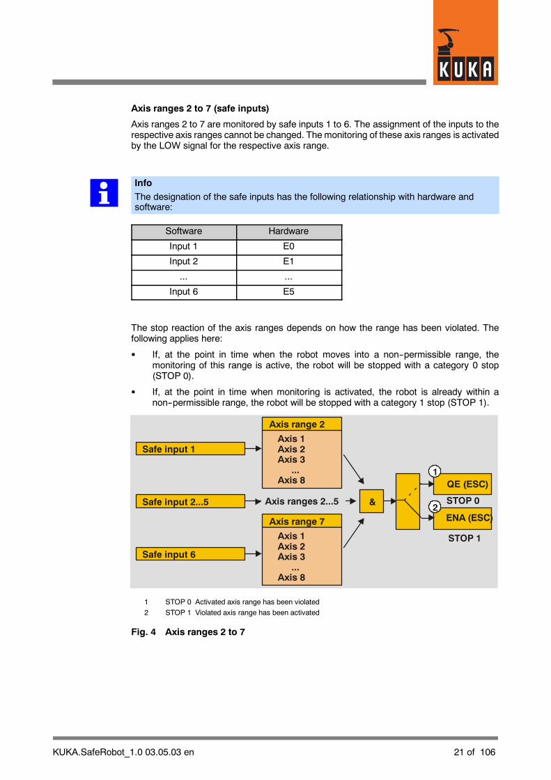
Axis ranges 2 to 7 (safe inputs)
Axis ranges 2 to 7 are monitored by safe inputs 1 to 6. The assignment of the inputs to therespective axis ranges cannot be changed. Themonitoring of these axis ranges is activatedby the LOW signal for the respective axis range.
InfoThe designation of the safe inputs has the following relationship with hardware andsoftware:
Software Hardware
Input 1 E0
Input 2 E1
... ...
Input 6 E5
The stop reaction of the axis ranges depends on how the range has been violated. Thefollowing applies here:
G If, at the point in time when the robot moves into a non--permissible range, themonitoring of this range is active, the robot will be stopped with a category 0 stop(STOP 0).
G If, at the point in time when monitoring is activated, the robot is already within anon--permissible range, the robot will be stopped with a category 1 stop (STOP 1).
QE (ESC)
ENA (ESC)
STOP 0
STOP 1
Safe input 1
Safe input 2...5
Safe input 6
Axis range 2
Axis range 7
Axis 1Axis 2Axis 3
...Axis 8
Axis 1Axis 2Axis 3
...Axis 8
&Axis ranges 2...5
1
2
1 STOP 0 Activated axis range has been violated
2 STOP 1 Violated axis range has been activated
Fig. 4 Axis ranges 2 to 7
22 of 106 KUKA.SafeRobot_1.0 03.05.03 en
The axis ranges 2 ... 7 can be configured as working ranges or safety ranges. This is doneusing the configuration program (see Section 5.3).
For each range the value can be set as:
G FALSE working range
G TRUE safety range
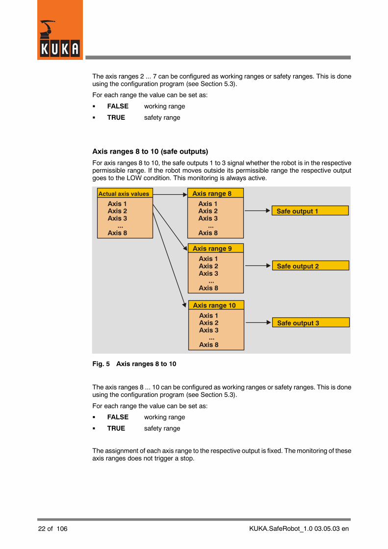
Axis ranges 8 to 10 (safe outputs)
For axis ranges 8 to 10, the safe outputs 1 to 3 signal whether the robot is in the respectivepermissible range. If the robot moves outside its permissible range the respective outputgoes to the LOW condition. This monitoring is always active.
Actual axis values
Safe output 1
Safe output 2
Axis range 8
Axis range 9
Axis 1Axis 2Axis 3
...Axis 8
Axis 1Axis 2Axis 3
...Axis 8
Axis 1Axis 2Axis 3
...Axis 8
Safe output 3
Axis range 10
Axis 1Axis 2Axis 3
...Axis 8
Fig. 5 Axis ranges 8 to 10
The axis ranges 8 ... 10 can be configured as working ranges or safety ranges. This is doneusing the configuration program (see Section 5.3).
For each range the value can be set as:
G FALSE working range
G TRUE safety range
The assignment of each axis range to the respective output is fixed. Themonitoring of theseaxis ranges does not trigger a stop.
KUKA.SafeRobot_1.0 03.05.03 en 23 of 106
3.2.8 Safe operational stop
The function “Safe operational stop” initiates monitoring of all robot axes; the drives remainunder control and the brakes are not applied. This function is activated by a safe input to theSafe RDC.
If these are not within a defined tolerance, the drive enable flag is withdrawn by means ofa safe output and the robot is stopped (STOP 0).
3.3 Configuration program
A configuration program is available for configuring and parameterizing the safe parameters.
The installation of this program is described in Section 5.2, and its operation is described inSection 5.3.

24 of 106 KUKA.SafeRobot_1.0 03.05.03 en
KUKA.SafeRobot_1.0 03.05.03 en 25 of 106
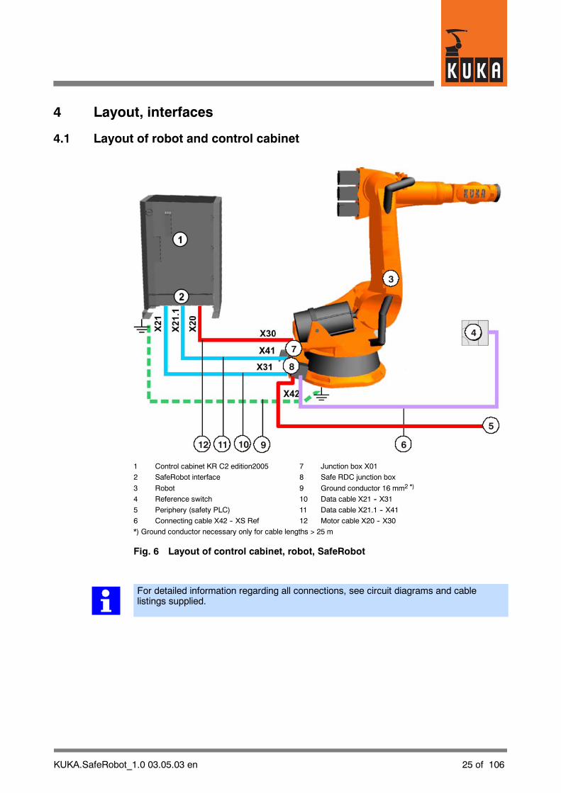
4 Layout, interfaces
4.1 Layout of robot and control cabinet
4
5
6
3
7
8
9101112
1 Control cabinet KR C2 edition2005 7 Junction box X01
2 SafeRobot interface 8 Safe RDC junction box
3 Robot 9 Ground conductor 16 mm2 *)
4 Reference switch 10 Data cable X21 -- X31
5 Periphery (safety PLC) 11 Data cable X21.1 -- X41
6 Connecting cable X42 -- XS Ref 12 Motor cable X20 -- X30
*) Ground conductor necessary only for cable lengths > 25 m
Fig. 6 Layout of control cabinet, robot, SafeRobot
For detailed information regarding all connections, see circuit diagrams and cablelistings supplied.

26 of 106 KUKA.SafeRobot_1.0 03.05.03 en
4.1.1 Junction boxes on the robotThe plug--in connections on the robot are located on the junction boxes on the base frame: onjunction box X01 for themotor cable, on X02 for the data cable. The arrangement of the junctionboxes and the associated connectors on the robot are as shown in the example in Fig. 7.
If connecting cables with a length > 25 m are used, a ground bolt must be provided on thebase frame for the ground conductor (Fig. 25).
The connectors for the motor cable X20 -- X30 and data cables X21 -- X31 and X21.1 --X41 are coded to avoid crossing over.
X41
X31
X30
X02
X01
Fig. 7 Junction boxes

KUKA.SafeRobot_1.0 03.05.03 en 27 of 106
4.1.2 Control cabinet KR C2 edition2005
The control cabinet KR C2 edition2005 (Fig. 8) has been suitably modified for theKUKA.SafeRobot option. The connection panel is accessed by opening the door to thecabinet.
The connected cables are routed under the control cabinet to the rear.
2
3
1
1 Power unit
2 Computer unit (KUKA PC2004)
3 Connection panel
Fig. 8 Control cabinet KR C2 edition2005 (for SafeRobot)
Detailed information regarding the KR C2 control cabinet and the modules shown herecan be found in the [KR C2 edition2005 Operating Handbook].

28 of 106 KUKA.SafeRobot_1.0 03.05.03 en
4.1.3 Connection panel on the control cabinet (standard)
The connection panel (Fig. 9) is accessed by opening the door to the cabinet.
The connected cables are routed under the control cabinet to the rear.
1 2 3 4 5
6
1 X1 Power supply connection 4 X21.1 Data cable, ESC -- Safe RDC2 X20 Motor connector, axes 1 to 6 5 X19 KCP connection3 X11 Customer interface 6 X21 Data cable, DSE -- Safe RDC
Fig. 9 Connection panel on the control cabinet (standard)
Depending on the motor package and cabinet option, the assignment of the connectorsand the motor connector design may differ from those shown.
The connection panel for the DaimlerChrysler variant is described in Section 4.1.4.

KUKA.SafeRobot_1.0 03.05.03 en 29 of 106
4.1.4 Connection panel on the control cabinet (DaimlerChrysler)
Fig. 10 shows the connection panel for the DaimlerChrysler variant.
1 2 3 4 5
6
1 X1 Power supply connection 4 X21.1 Data cable, ESC -- Safe RDC2 X20 Motor connector, axes 1 to 6 5 X19 KCP connection3 X11 Customer interface 6 X21 Data cable, DSE -- Safe RDC
Fig. 10 Connection panel on the control cabinet (DaimlerChrysler)

30 of 106 KUKA.SafeRobot_1.0 03.05.03 en
4.2 SafeRobot control cabinet components
4.2.1 Multi--function card MFC 3 Tech
The multi--function card MFC 3 in the PCI--BUS version contains the inputs and outputs forthe system.
This card has the following properties:
G RTAcc chip for VxWinRT (real--time function)
G DeviceNet/CAN bus connection
G Interface with the DSE
Fig. 11 Multi--function card MFC3 Tech
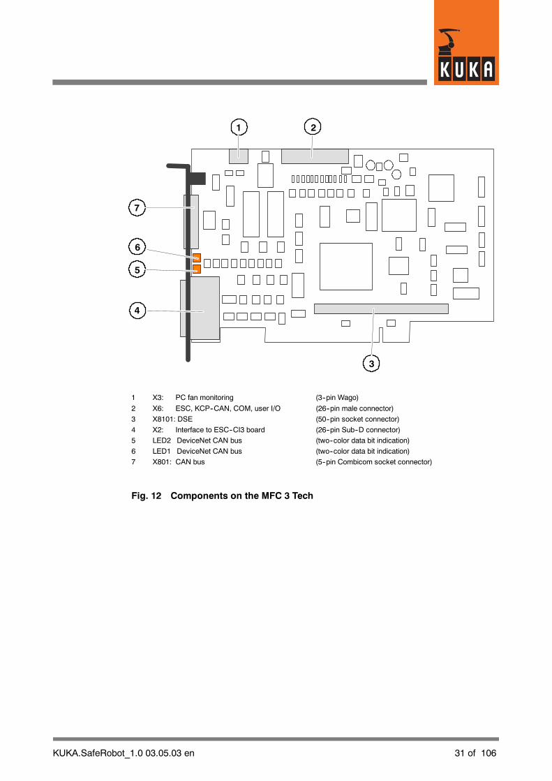
KUKA.SafeRobot_1.0 03.05.03 en 31 of 106
7
4
1 2
3
6
5
1 X3: PC fan monitoring (3--pin Wago)
2 X6: ESC, KCP--CAN, COM, user I/O (26--pin male connector)
3 X8101: DSE (50--pin socket connector)
4 X2: Interface to ESC--CI3 board (26--pin Sub--D connector)
5 LED2 DeviceNet CAN bus (two--color data bit indication)
6 LED1 DeviceNet CAN bus (two--color data bit indication)
7 X801: CAN bus (5--pin Combicom socket connector)
Fig. 12 Components on the MFC 3 Tech
32 of 106 KUKA.SafeRobot_1.0 03.05.03 en
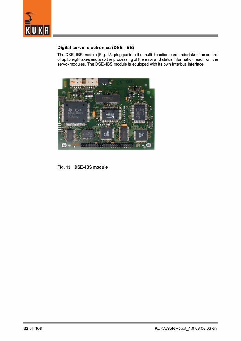
Digital servo--electronics (DSE--IBS)
The DSE--IBS module (Fig. 13) plugged into the multi--function card undertakes the controlof up to eight axes and also the processing of the error and status information read from theservo--modules. The DSE--IBS module is equipped with its own Interbus interface.
Fig. 13 DSE--IBS module
KUKA.SafeRobot_1.0 03.05.03 en 33 of 106
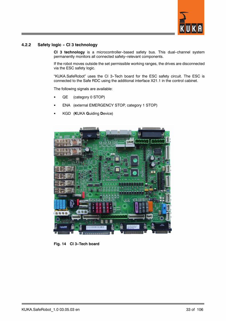
4.2.2 Safety logic -- CI 3 technology
CI 3 technology is a microcontroller--based safety bus. This dual--channel systempermanently monitors all connected safety--relevant components.
If the robot moves outside the set permissible working ranges, the drives are disconnectedvia the ESC safety logic.
“KUKA.SafeRobot” uses the CI 3--Tech board for the ESC safety circuit. The ESC isconnected to the Safe RDC using the additional interface X21.1 in the control cabinet.
The following signals are available:
G QE (category 0 STOP)
G ENA (external EMERGENCY STOP, category 1 STOP)
G KGD (KUKA Guiding Device)
Fig. 14 CI 3--Tech board

34 of 106 KUKA.SafeRobot_1.0 03.05.03 en
CI 3--Tech board components and connections
Connectordesignation
Function
X1 Internal 24 V power supply
X2 KPS connection
X3 MFC connection
X4 External mode selector switch connection (optional)
X5 KCP connection
X6 Connector for internal/external power supply and ESC circuit
X7 CAN connection, I/O board (optional)
X8 Connection of external controllers, EMERGENCY--STOP button oncabinet
X10 Spare
X11 Safe input E7 (SafeRobot option)
X12 Periphery interface outputs >500 mA
X13 SafetyBUS Gateway interface (optional)
X16 Cobra Control (CC) interface, Common Control Cabinet (CCC)(optional)
X18 Interface to MFC3 (CR safety signals) (optional)
X19 Interface to CR lamp (optional)
X20 Interface to selector switch in Shared Pendant (optional)
X21 KCP power supply and KCP CAN
X22 Periphery interface inputs and outputs
X23 Safe RDC interface (optional)
X24 CR OUT interface (optional)
X25 CR IN interface (optional)
X26 KUKA Guiding Device (KGD) interface (optional)
X27 Multi--power tap (DeviceNet on MFC) (optional)
X28 Multi--power tap (OUT1) (optional)
X29 Multi--power tap (OUT2) (optional)
X30 Spare
X31 Internal cabinet fan connection
KUKA.SafeRobot_1.0 03.05.03 en 35 of 106
Fuses
The fuses are rated for voltages of up to 35 V. By every fuse on the board is a red LEDwhichlights up if the fuse is defective.
Fusedesignation
Fuse rating Function
F2 2 A Fan monitoring in cabinet
F10 3 A ESC supply voltage
F13 4 A Periphery
F21 2 A CR lamp
F23 2 A RDC supply
F24 2 A Multi--power tap supply
Relays
Relaydesignation
Function
K1 Message: Drives ON
K2 Message: Drives ON
K3 Message: Local EMERGENCY STOP
K4 Message: Local EMERGENCY STOP
K7 Message: TEST mode
K8 Message: AUTOMATIC mode
36 of 106 KUKA.SafeRobot_1.0 03.05.03 en
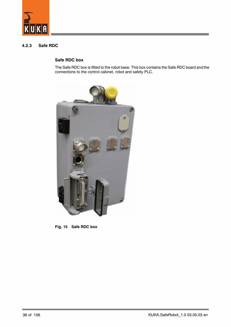
4.2.3 Safe RDC
Safe RDC box
The Safe RDC box is fitted to the robot base. This box contains the Safe RDCboard and theconnections to the control cabinet, robot and safety PLC.
Fig. 15 Safe RDC box
KUKA.SafeRobot_1.0 03.05.03 en 37 of 106
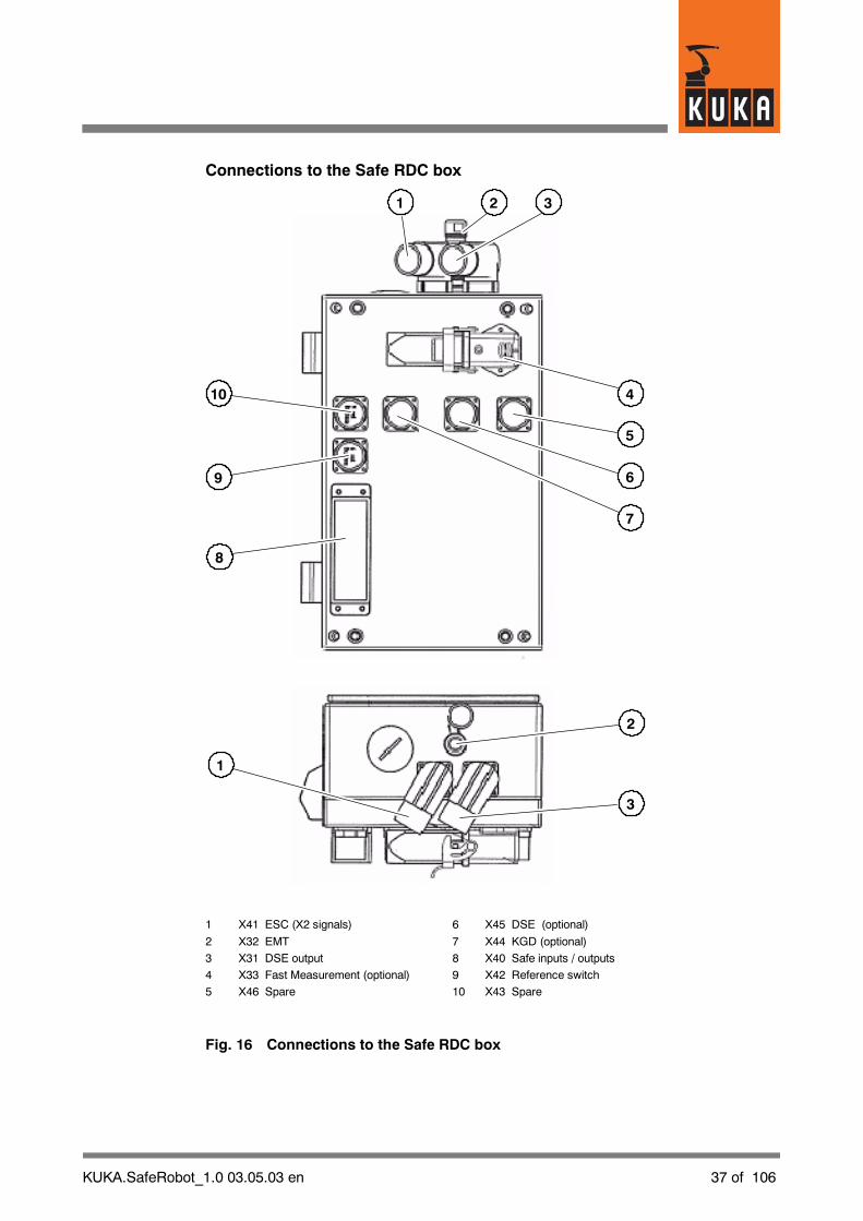
Connections to the Safe RDC box
21
5
4
6
7
3
9
8
10
2
1
3
1 X41 ESC (X2 signals) 6 X45 DSE (optional)
2 X32 EMT 7 X44 KGD (optional)
3 X31 DSE output 8 X40 Safe inputs / outputs
4 X33 Fast Measurement (optional) 9 X42 Reference switch
5 X46 Spare 10 X43 Spare
Fig. 16 Connections to the Safe RDC box
38 of 106 KUKA.SafeRobot_1.0 03.05.03 en
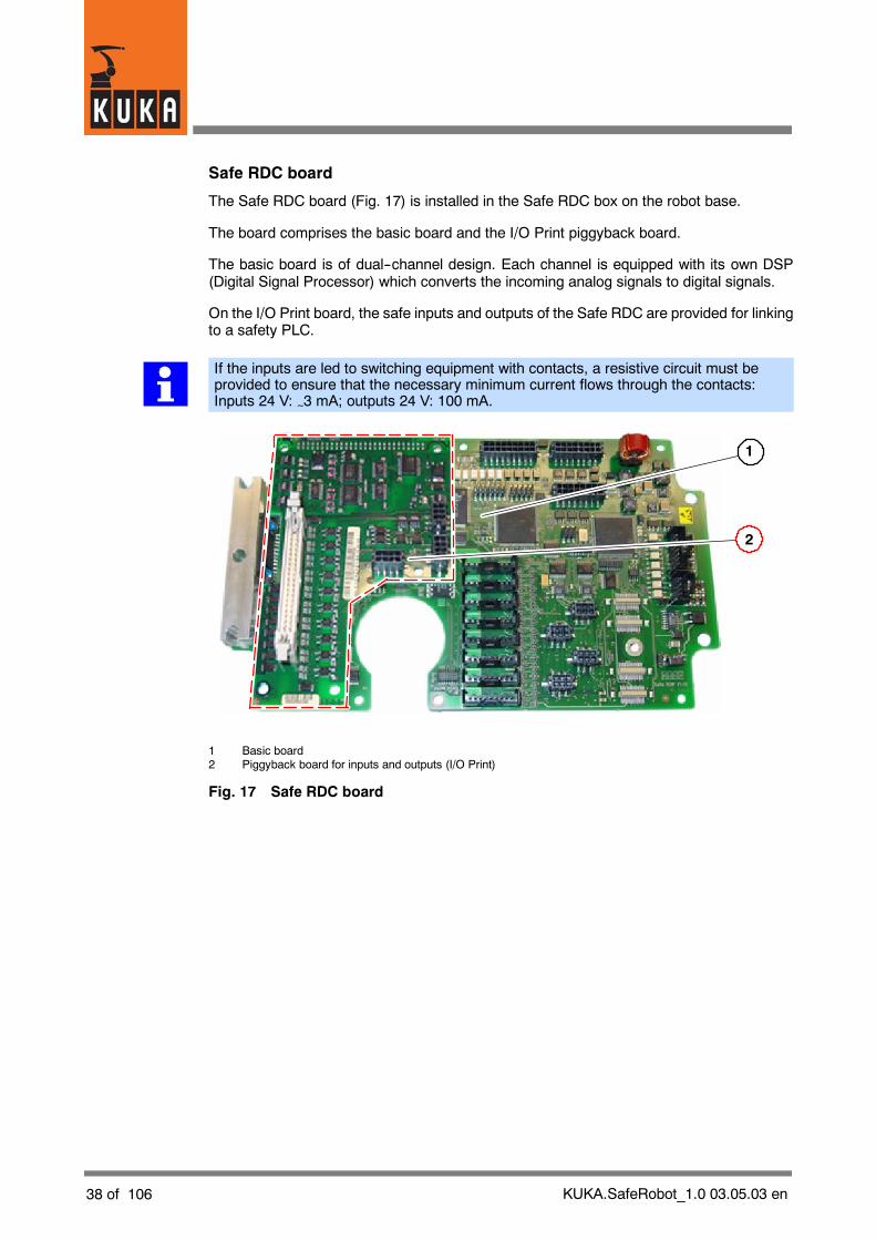
Safe RDC board
The Safe RDC board (Fig. 17) is installed in the Safe RDC box on the robot base.
The board comprises the basic board and the I/O Print piggyback board.
The basic board is of dual--channel design. Each channel is equipped with its own DSP(Digital Signal Processor) which converts the incoming analog signals to digital signals.
On the I/O Print board, the safe inputs and outputs of the Safe RDC are provided for linkingto a safety PLC.
If the inputs are led to switching equipment with contacts, a resistive circuit must beprovided to ensure that the necessary minimum current flows through the contacts:Inputs 24 V: ~3 mA; outputs 24 V: 100 mA.
1
2
1 Basic board2 Piggyback board for inputs and outputs (I/O Print)
Fig. 17 Safe RDC board

KUKA.SafeRobot_1.0 03.05.03 en 39 of 106
The Safe RDC performs the following functions:
G Generation of all necessary operating voltages from the supply voltage
G Evaluating the resolvers for 8 axes
G A/D conversion of up to 8 axes
G A/D conversion of 8 temperature sensors
G Evaluation of an EMT
G Open--circuit monitoring of the resolvers
G Motor temperature monitoring
G Communication with the DSE--IBS via an RS422 serial interface
G Fast Measurement
G Sensing circuit board temperature
The following safety--relevant monitoring features are available:
G Safe reduced velocity/acceleration (axis--specific)
G Safe reduced velocity (Cartesian) at the flange
G Safe position sensing system
G Safe axis range monitoring
G Safe operational stop
G Safe stop (ESC function)
G Monitoring of robot mastering
G Brake test
G Safe disconnection of drives in accordance with Stop 0 or Stop 1
Safe inputs and outputs
The following safe inputs are provided on the basic board: Corob_En and E_T1 and also thesafe outputs: QE_A/B and ENA A/B.
The safe inputs: E0 -- E5 (axis ranges 1 -- 6), reference switch, safe retraction, safe stop,reduced velocity and KGDand also the safe outputs: A0 -- A2 (axis ranges), status and spareoutput are on the I/O Print board.

40 of 106 KUKA.SafeRobot_1.0 03.05.03 en
Connections to the Safe RDC board
X8
X7
X6
X5
X4
X3
X2
X1
1 2 3 4
9
8
5
6
101112131415
7
1 X2000 Connection to I/O Print board 9 X1207 Sensor module slot
2 X901 ESC signals 10 X1208 Sensor module slot
3 X900 Connection to DSE (channel A) 11 X1200 Sensor connector
4 X1000 Connection to DSE (channel B) 12 X1202 Sensor connector
5 X1301 “Fast Measurement” connection 13 X1203 Sensor connector
6 X1300 EMT connection 14 X1201 Sensor connector
7 X1204 Sensor module slot 15 X1--X8 Resolver connector
8 X1205 Sensor module slot
Fig. 18 Connections to the basic board
KUKA.SafeRobot_1.0 03.05.03 en 41 of 106
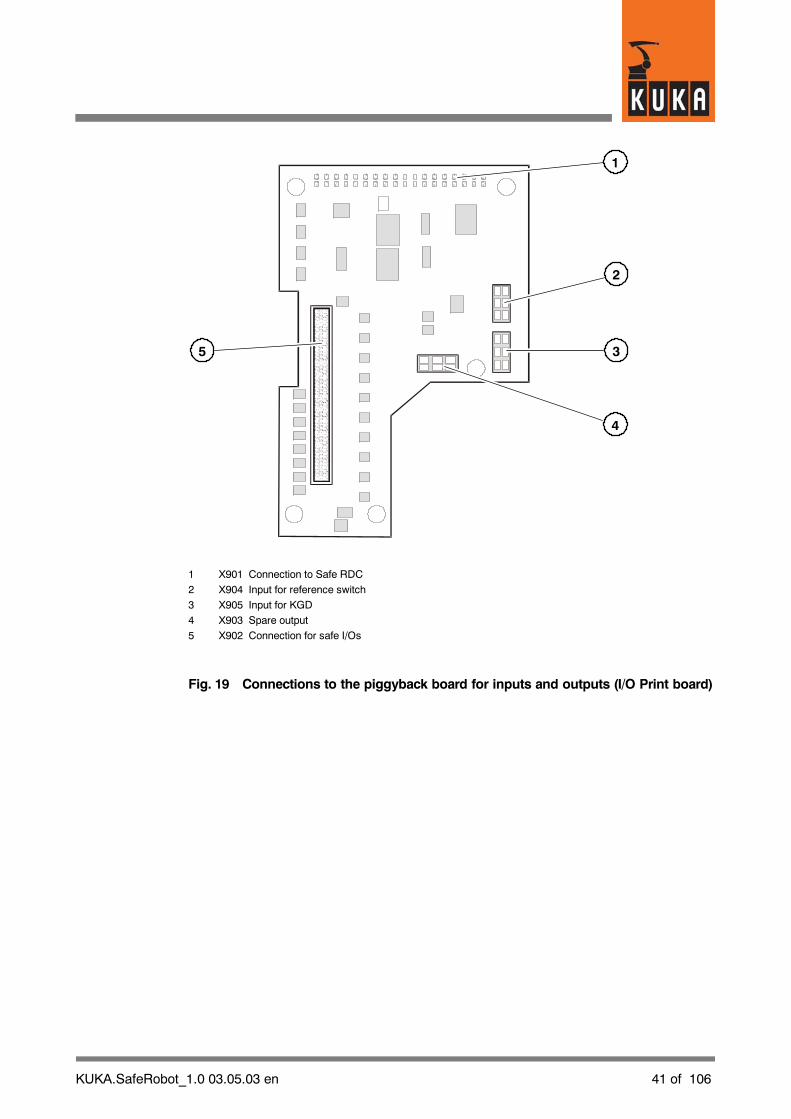
2
3
1
4
5
1 X901 Connection to Safe RDC
2 X904 Input for reference switch
3 X905 Input for KGD
4 X903 Spare output
5 X902 Connection for safe I/Os
Fig. 19 Connections to the piggyback board for inputs and outputs (I/O Print board)
42 of 106 KUKA.SafeRobot_1.0 03.05.03 en
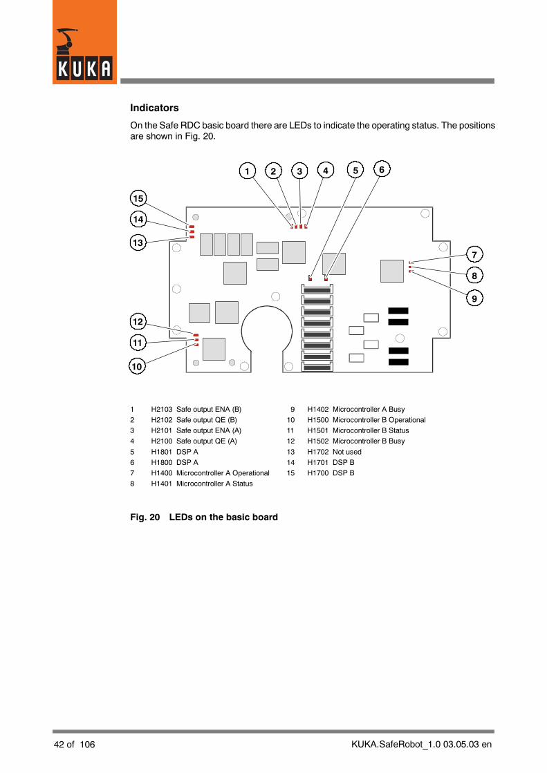
Indicators
On the Safe RDC basic board there are LEDs to indicate the operating status. The positionsare shown in Fig. 20.
1 2 3 4
8
9
7
5 6
14
13
15
11
10
12
1 H2103 Safe output ENA (B) 9 H1402 Microcontroller A Busy
2 H2102 Safe output QE (B) 10 H1500 Microcontroller B Operational
3 H2101 Safe output ENA (A) 11 H1501 Microcontroller B Status
4 H2100 Safe output QE (A) 12 H1502 Microcontroller B Busy
5 H1801 DSP A 13 H1702 Not used
6 H1800 DSP A 14 H1701 DSP B
7 H1400 Microcontroller A Operational 15 H1700 DSP B
8 H1401 Microcontroller A Status
Fig. 20 LEDs on the basic board

KUKA.SafeRobot_1.0 03.05.03 en 43 of 106
Meaning of the LEDs for the safe outputs
The statuses of the safe outputs are shown by the LEDs H2100 to 2103 (see Fig. 20). Theassignment of LEDs to outputs and the meaning of the indications is described in thefollowing table.
LED Safe output Meaning
H2100(green)
QE (A)STOP 0 A channelOn: Output has HIGH signal
H2101(green)
ENA (A)STOP 1 A channelOn: Output has HIGH signal
H2102(green)
QE (B)STOP 0 B channelOn: Output has HIGH signal
H2103(green)
ENA (B)STOP 1 B channelOn: Output has HIGH signal
If all four LEDs (H2100 ... 2103) are lit, no safety stop (STOP 0 or STOP 1) is active.Assuming that no other stop condition is prevailing (such as EMERGENCY STOP atthe KCP) the robot can move.
Description of the LEDs for the microcontrollers
The current operatingmode and status for microcontrollers A and B is indicated by the LEDsH1400 ... H1403 andH1500 ... 1503 (see Fig. 20). Themeaningof the indications at boot--upand during normal operation is described in the following table.
LED Boot--up Normal operation
H1400 MC A(green)
H1500 MC B(green)
Operation
Off: Cannot operate,serious error
On: Boot loader running
Flashing: Firmware defective
Operation
Off: Cannot operate,serious error
Flashing: Normal operation
H1401 MC A(green)
H1501 MC B(green)
State
Off: Initialization error
On: Initialization ended
State
Off: Normal operation
On: DPRAM for DSPfrozen
Flashing: Waiting for synchro-nization signal
H1402 MC A(red)
H1502 MC B(red)
Busy
Off: Waiting forcommand
On: Command beingexecuted
Busy
Off: Waiting forcommand
On: Command beingexecuted

44 of 106 KUKA.SafeRobot_1.0 03.05.03 en
Description of the LEDs for the DSP
The current status of the DSP is indicated by the LEDs H1700, H1701, H1800 and H1801.The meaning of the indications at boot--up and during normal operation is described in thefollowing table.
LED Boot--up Normal operation
H1800 DSP A(green)
H1700 DSP B(green)
Operation
Off: Cannot operate,serious error
On: Boot loader running
Operation
Off: Cannot operate,serious error
Flashing: Normal operation
H1800 DSP A(red)
H1700 DSP B(red)
State
On: Error during DSP test
Lights up briefly:Data transmissionrunning
State
Not connected

KUKA.SafeRobot_1.0 03.05.03 en 45 of 106
4.2.4 Interfaces to the Safe RDC
DSE signals, Safe RDC -- connection X31
X31Pin
Signal name Description
01 +24V_CR 24V supply to the CR lamp on the robot
02 GND_PReference potential for the 24V supply to the Safe RDCfrom the control cabinet
03 +24V 24V supply to the Safe RDC from the control cabinet
04 /A_CLKR1 SSI interface to DSE channel A
05 A_CLKR1 SSI interface to DSE channel A
06 A_FSX1 SSI interface to DSE channel A
07 /A_FSX1 SSI interface to DSE channel A
08 A_DX1 SSI interface to DSE channel A
09 /A_DX1 SSI interface to DSE channel A
10 /A_FSR1 SSI interface to DSE channel A
11 A_FSR1 SSI interface to DSE channel A
12 /A_DR1 SSI interface to DSE channel A
13 A_DR1 SSI interface to DSE channel A
14 /A_CLKX1 SSI interface to DSE channel A
15 A_CLKX1 SSI interface to DSE channel A
17 GND--CRReference potential for the 24V supply to the CR lamp onthe robot
EMT signals, Safe RDC -- connection X32
X32Pin
Name Description
01 GND--P Reference potential for the 24V supply
02 24V--P 24 V supply
05 EMT2 EMT input 2
06 EMT1 EMT input 1
46 of 106 KUKA.SafeRobot_1.0 03.05.03 en
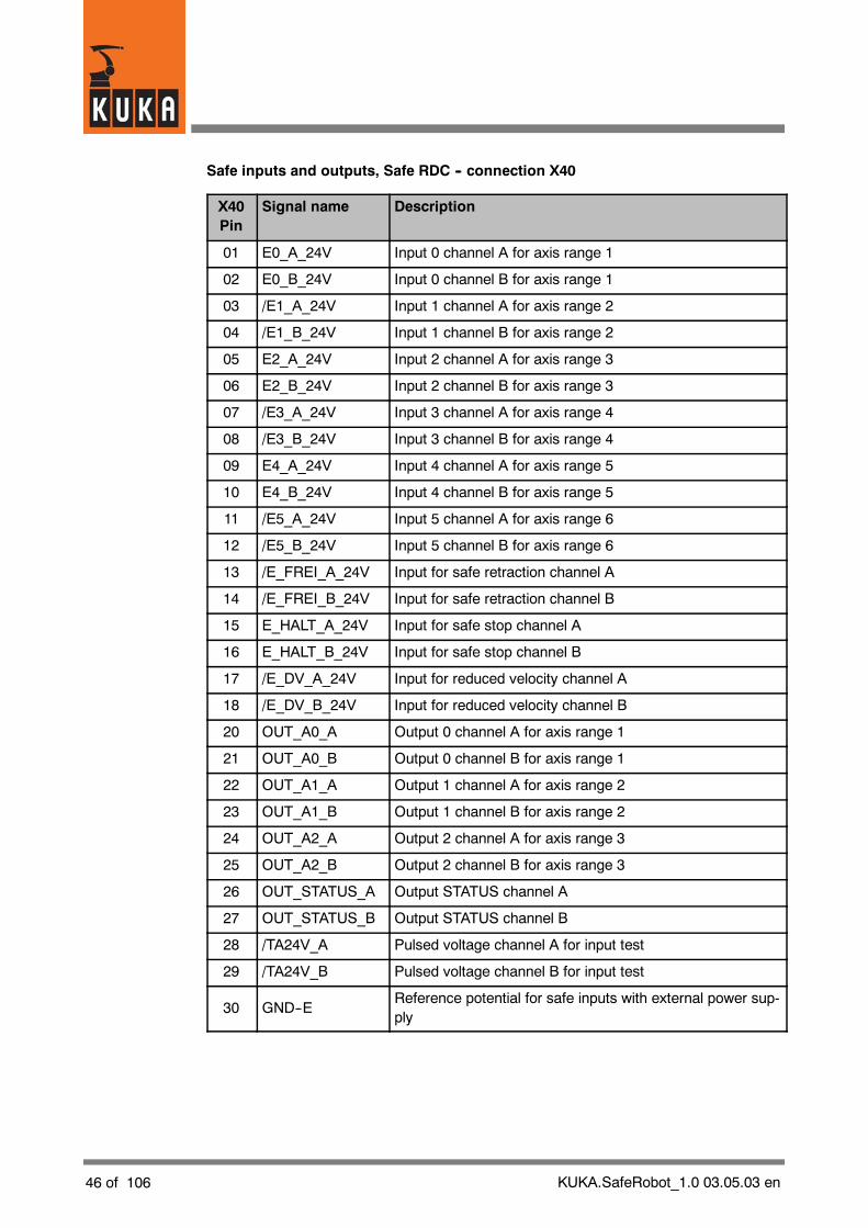
Safe inputs and outputs, Safe RDC -- connection X40
X40Pin
Signal name Description
01 E0_A_24V Input 0 channel A for axis range 1
02 E0_B_24V Input 0 channel B for axis range 1
03 /E1_A_24V Input 1 channel A for axis range 2
04 /E1_B_24V Input 1 channel B for axis range 2
05 E2_A_24V Input 2 channel A for axis range 3
06 E2_B_24V Input 2 channel B for axis range 3
07 /E3_A_24V Input 3 channel A for axis range 4
08 /E3_B_24V Input 3 channel B for axis range 4
09 E4_A_24V Input 4 channel A for axis range 5
10 E4_B_24V Input 4 channel B for axis range 5
11 /E5_A_24V Input 5 channel A for axis range 6
12 /E5_B_24V Input 5 channel B for axis range 6
13 /E_FREI_A_24V Input for safe retraction channel A
14 /E_FREI_B_24V Input for safe retraction channel B
15 E_HALT_A_24V Input for safe stop channel A
16 E_HALT_B_24V Input for safe stop channel B
17 /E_DV_A_24V Input for reduced velocity channel A
18 /E_DV_B_24V Input for reduced velocity channel B
20 OUT_A0_A Output 0 channel A for axis range 1
21 OUT_A0_B Output 0 channel B for axis range 1
22 OUT_A1_A Output 1 channel A for axis range 2
23 OUT_A1_B Output 1 channel B for axis range 2
24 OUT_A2_A Output 2 channel A for axis range 3
25 OUT_A2_B Output 2 channel B for axis range 3
26 OUT_STATUS_A Output STATUS channel A
27 OUT_STATUS_B Output STATUS channel B
28 /TA24V_A Pulsed voltage channel A for input test
29 /TA24V_B Pulsed voltage channel B for input test
30 GND--EReference potential for safe inputs with external power sup-ply
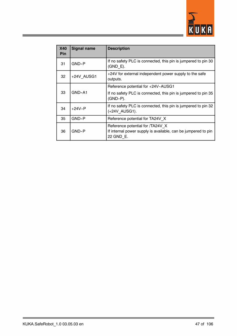
KUKA.SafeRobot_1.0 03.05.03 en 47 of 106
X40Pin
Signal name Description
31 GND--PIf no safety PLC is connected, this pin is jumpered to pin 30(GND_E).
32 +24V_AUSG1+24V for external independent power supply to the safeoutputs.
33 GND--A1
Reference potential for +24V--AUSG1
If no safety PLC is connected, this pin is jumpered to pin 35(GND--P).
34 +24V--PIf no safety PLC is connected, this pin is jumpered to pin 32(+24V_AUSG1).
35 GND--P Reference potential for TA24V_X
36 GND--PReference potential for /TA24V_XIf internal power supply is available, can be jumpered to pin22 GND_E.

48 of 106 KUKA.SafeRobot_1.0 03.05.03 en
ESC signals, Safe RDC -- connection X41
X41Pin
Signal name Description
01 TA 24V (A) --ESCPulsed voltage coming from ESC--CI3, power supply tooutputs QE_A and ENA_A
02 GND ESC Reference potential for TA 24V (A and B) ESC
03 TA 24V (B) --ESCPulsed voltage coming from ESC--CI3, power supply tooutputs QE_B and ENA_B
04 ENA_A_24VSafe output,ENA channel A (Stop 1) to ESC--CI3 board
05 ENA_B_24VSafe output,ENA channel B (Stop 1) to ESC--CI3 board
06 QE_A_24VSafe output,QE channel A (Stop 0) to ESC--CI3 board
07 QE_B_24VSafe output,QE channel B (Stop 0) to ESC--CI3 board
08 TA 24V (B) Pulsed voltage for channel B input test
09 TA 24V (A) Pulsed voltage for channel A input test
10 E_T1_A_24V Safe input, test 1 channel A
11 E_T1_B_24V Safe input, test 1 channel B
12COROB_EN_A_24V
Safe input,for activating the KGD function channel A
13COROB_EN_B_24V
Safe input,for activating the KGD function channel B
14 GND--E Reference potential for safe inputs with external power supply
15 GND--PIf internal power supply is available, is jumpered to pin 30GND_E
16 Reserved Coding pin
17 N.C. Not connected
KUKA.SafeRobot_1.0 03.05.03 en 49 of 106
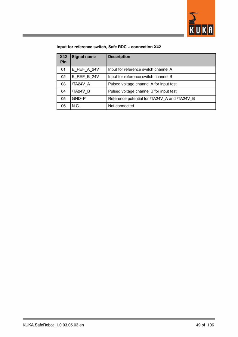
Input for reference switch, Safe RDC -- connection X42
X42Pin
Signal name Description
01 E_REF_A_24V Input for reference switch channel A
02 E_REF_B_24V Input for reference switch channel B
03 /TA24V_A Pulsed voltage channel A for input test
04 /TA24V_B Pulsed voltage channel B for input test
05 GND--P Reference potential for /TA24V_A and /TA24V_B
06 N.C. Not connected

50 of 106 KUKA.SafeRobot_1.0 03.05.03 en
Connection KCP X19 (control cabinet KR C2 edition2005) toconnector X20 (ESC CI3 board)
X19Pin
Name Description X20Pin
A DISPLAY+
B DISPLAY--
C SW_Selection(A) Switch setting “Selection” to SSB 3
D SW_Release(B) Switch setting “Release” to SSB 4
1+24 V KCPvoltage
2 GND
3+24 V ESCvoltage
4 GND
5 ESC In (B)
6 ESC In (A)
7 ESC Out (B)
8 ESC Out (A)
9 CAN +
10 CAN --
11 CR_TA(A) 24V test output A from CR logic 1
12 T1--A Safe input, operating mode T1 channel A 5
13 CR_TA(B) 24V test output B from CR logic 2
14 T2--B Safe input, operating mode T1 channel B 6

KUKA.SafeRobot_1.0 03.05.03 en 51 of 106
DSE signals
Connection X31 (Safe RDC box) to connection X21 (control cabinet KR C2)
X31Pin
Name Description X21Pin
01 +24V CR 24V supply to the CR lamp on the robot 1
02 GND--PReference potential for the 24V supply to the SafeRDC from the control cabinet
2
03 +24V24V supply to Safe RDCfrom control cabinet
3
04 /A_CLKR1 SSI interface to DSE channel A 4
05 A_CLKR1 SSI interface to DSE channel A 5
06 /A_FSX1 SSI interface to DSE channel A 6
07 A_FSX1 SSI interface to DSE channel A 7
08 A_DX1 SSI interface to DSE channel A 8
09 /A_DX1 SSI interface to DSE channel A 9
10 /A_FSR1 SSI interface to DSE channel A 10
11 A_FSR1 SSI interface to DSE channel A 11
12 /A_DR1 SSI interface to DSE channel A 12
13 A_DR1 SSI interface to DSE channel A 13
14 /A_CLKX1 SSI interface to DSE channel A 14
15 A_CLKX1 SSI interface to DSE channel A 15
17 GND--CRReference potential for the 24V supply to the CRlamp on the robot
17

52 of 106 KUKA.SafeRobot_1.0 03.05.03 en
ESC signals (QE, ENA, T1)
Connection X41 (Safe RDC box) to connection X21.1 (control cabinet KR C2)
X41Pin
Signal name Description X21.1Pin
1 TA 24V (A) --ESCPulsed voltage coming from ESC--CI3, powersupply to outputs QE_A and ENA_A
2
2 GND ESC Reference potential for TA 24V (A and B) ESC 1
3 TA 24V (B) --ESCPulsed voltage coming from ESC--CI3, powersupply to outputs QE_B and ENA_B
3
4 ENA_A_24VSafe output,ENA channel A (Stop 1) to ESC--CI3 board
8
5 ENA_B_24VSafe output,ENA channel B (Stop 1) to ESC--CI3 board
9
6 QE_A_24VSafe output,QE channel A (Stop 0) to ESC--CI3 board
6
7 QE_B_24VSafe output,QE channel B (Stop 0) to ESC--CI3 board
7
8 TA 24V (B) Pulsed voltage for channel B input test 4
9 TA 24V (A) Pulsed voltage for channel A input test 5
10 E_T1_A_24V Safe input, test 1 channel A 10
11 E_T1_B_24V Safe input, test 1 channel B 11
12COROB_EN_A_24V
Safe input,for activating the KGD function channel A
12
13COROB_EN_B_24V
Safe input,for activating the KGD function channel B
13
14 GND_EReference potential for safe inputs with externalpower supply
14
15 GND--PIf internal power supply is available, is jumpered topin 30 GND_E
15
16 Reserved Coding pin 16
17 N.C. Not connected 17
KUKA.SafeRobot_1.0 03.05.03 en 53 of 106
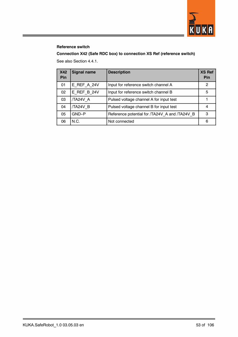
Reference switch
Connection X42 (Safe RDC box) to connection XS Ref (reference switch)
See also Section 4.4.1.
X42Pin
Signal name Description XS RefPin
01 E_REF_A_24V Input for reference switch channel A 2
02 E_REF_B_24V Input for reference switch channel B 5
03 /TA24V_A Pulsed voltage channel A for input test 1
04 /TA24V_B Pulsed voltage channel B for input test 4
05 GND--P Reference potential for /TA24V_A and /TA24V_B 3
06 N.C. Not connected 6

54 of 106 KUKA.SafeRobot_1.0 03.05.03 en
4.3 Connecting cables between robot and control cabinet
4.3.1 Connecting cables diagram
3
4
5
6789
1 Control cabinet KR C2 edition2005 6 Ground conductor 16 mm2 *)
2 SafeRobot interface 7 Data cable X21 -- X31
3 Robot 8 Data cable X21.1 -- X41
4 Junction box X01 9 Motor cable X20 -- X30
5 Safe RDC junction box
*) Ground conductor necessary only for cable lengths > 25 m
Fig. 21 Connecting cables between control cabinet and robot, Safe RDC
KUKA.SafeRobot_1.0 03.05.03 en 55 of 106
4.3.2 Connecting cables
Connecting cables are all the cables running between the robot and the control cabinet(Fig. 21). They haveplug--in connections at both ends. In order to avoid the connectors beingmixed up, the ends of each cable are provided with a designation label, which must matchthedesignation of the socket on the robot or on the control cabinet. In addition the connectorsare coded.
The connectors must be plugged in carefully so as not to bend the contact pins.
For connecting cables of length > 25m an additional ground conductor is required to providea low--resistance connection in accordance with DIN EN 60204.The ground conductors are fastened with cable lugs to threaded bolts.
Routing of cables
The following points must be observed when routing the cables:
-- The minimum bending radius of the cables (150 mm for fixed installation) must beobserved.
-- Protect cables against exposure to mechanical stress.
-- Route the cables without tension (no tensile forces on the connectors).
-- Cables are only to be installed indoors.
-- Observe permissible temperature range (fixed installation) 263 K (--10 _C) to343 K (+70 _C).
-- Route power cables separately from the control cables (such as data cables, buscables).

56 of 106 KUKA.SafeRobot_1.0 03.05.03 en
4.3.3 Configuration of the connecting cables
X20 X30
X20 X30
a f F A
Fig. 22 Motor cable, X20 -- X30
X21 X31
X21 X31
21
3
1 Coding pin 3 Barcode plate
2 Coding hole
Fig. 23 Data cable X21 -- X31
X21.1 X41
1 2
X21.1 X41
3
21
3
1 Coding hole 3 Barcode plate
2 Coding pin
Fig. 24 Data cable X21.1 -- X41

KUKA.SafeRobot_1.0 03.05.03 en 57 of 106
PE
10
1
2
4
5
6
8
9
3
7
1 PE bolt: M8x30 stud bolt 6 M8 nutmech. galv. DIN 913 7 Washer 8.4
2 Cable lug 8 VS8 washer3 Robot 9 M8 nut4 Ground plate 10 Ring cable lug,5 Washer VS8 hole 8.4 mm
Fig. 25 Ground conductor connection
4.3.4 Interface assignments
The pin assignments for the connecting cables and their signal designations aredescribed in Section 4.2.3.

58 of 106 KUKA.SafeRobot_1.0 03.05.03 en
4.4 Reference switch
For safe operation, a reference run must be performed every time the robot controller isbooted up, and also at specified intervals during continuous operation (see Section 5.4.2).
For this purpose a reference switch must be installed within the possible working range ofthe robot. This reference switch should be installed outside the process range of the robotand must not be at the mastering position of the robot or at a singularity position.
The function of the reference run is described in Section 5.4.2 of this documentation, anda program example is shown in Section 7.1.
1 2
345
1 Process range within the working range 4 Reference switch2 Range outside the process range 5 Reference switch actuating plate3 Construction for mounting the reference switch
Fig. 26 Reference switch: working range, process range

KUKA.SafeRobot_1.0 03.05.03 en 59 of 106
XS Ref
1
23
4
5
1 Control cabinet KR C2 edition2005 4 Connecting cable X42 -- XS Ref
2 Robot 5 Safe RDC junction box
3 Reference switch
Fig. 27 Interface, SafeRobot -- reference switch

60 of 106 KUKA.SafeRobot_1.0 03.05.03 en
4.4.1 Components for reference switch
The following components are necessary:
G Reference switch (KUKA)installed in the working range of the robot
G Reference switch actuating plate (KUKA)installed on the robot wrist, projecting beyond the flange
G Connecting cable for reference switch, 15 m (KUKA)to interface X42 on the Safe RDC
Fig. 28 Reference switch with position of fastening holes
Fig. 29 Reference switch actuating plate with position of fastening holes

KUKA.SafeRobot_1.0 03.05.03 en 61 of 106
X42 XS Ref
Fig. 30 Connecting cable X42 -- XS Ref (length: 15 m)
/TA24V_A
/TA24V_B
E_REF_A_24V
GND--P
E_REF_B_24V
N.C. N.C.
3
1
5
4
2
6
1
2
3
4
5
6
X42 XS Ref
1 32
1 Safe RDC
2 Connecting cable X42 -- XS Ref
3 Reference switch
Fig. 31 Pin assignment for connector X42, reference switch
62 of 106 KUKA.SafeRobot_1.0 03.05.03 en
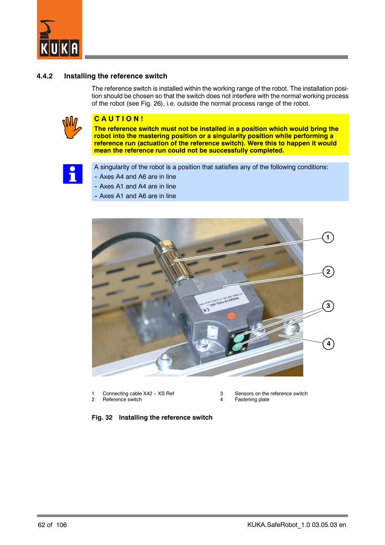
4.4.2 Installing the reference switch
The reference switch is installed within the working range of the robot. The installation posi-tion should be chosen so that the switch does not interfere with the normal working processof the robot (see Fig. 26), i.e. outside the normal process range of the robot.
C A U T I O N !The reference switch must not be installed in a position which would bring therobot into the mastering position or a singularity position while performing areference run (actuation of the reference switch). Were this to happen it wouldmean the reference run could not be successfully completed.
A singularity of the robot is a position that satisfies any of the following conditions:
-- Axes A4 and A6 are in line
-- Axes A1 and A4 are in line
-- Axes A1 and A6 are in line
1
3
2
4
1 Connecting cable X42 -- XS Ref 3 Sensors on the reference switch2 Reference switch 4 Fastening plate
Fig. 32 Installing the reference switch

KUKA.SafeRobot_1.0 03.05.03 en 63 of 106
1
3
2
1 Robot flange2 Tool3 Reference switch actuating plate
Fig. 33 Actuating plate for reference switch
Installation
G At a suitable position, set up a sufficiently stable mechanical mounting to carry thereference switch. An example is shown in Fig. 32.
G Secure the reference switch to it using the holes provided for the purpose (see Fig. 28and Fig. 32).
G Connect the reference switch to the X42 interface on the Safe RDC using theconnecting cable (see Fig. 30 and Fig. 32).
G Fit the actuating plate (see Fig. 29 and Fig. 33) to the robot wrist, so that this projectsbeyond the flange.
It must be ensured that the reference switch and actuating plate are installed in such a waythat the switching sensors (see Fig. 32) integrated in the reference switch can be correctlyapproached with the forked actuating plate.
The sensors can be approached forwards or sideways, as shown in Fig. 34, but always sothat theactuating plate pointswith the fork towards the twosensor markings on the referenceswitch.
The operation of the reference switch can be checked using the LED indicator on the rearof the reference switch (see Fig. 28).

64 of 106 KUKA.SafeRobot_1.0 03.05.03 en
1
2
3
4
1 Reference switch 3 Actuating plate for the reference switch2 Sensors on the reference switch 4 Possible approach directions to the
reference switch
Fig. 34 Reference switch, actuating plate -- possible approach directions
4.5 Keyswitch for “safe retraction” mode“Safe retraction” mode can be activated for moving the robot free undermanual control. Thisis done by setting the safe input “Safe retraction”.
For this purpose a keyswitch can be installed at a suitable point, with which the input “Saferetraction channel A” or “Safe retraction channel B” (see Section 4.2.3, Safe inputs and out-puts, Safe RDC -- connection X40) can be set to the HIGH signal.
4.6 Periphery“KUKA.SafeRobot” allows connection of a safety PLC.
NOTEIf the robot is operated without a PLC, the Safe RDC interface X40 must be connectedas described in Section 4.7.
4.6.1 Example of connection to a safety PLC (Siemens ET200S)
An example of connection of the safe outputs of a safety PLC to the safe inputs of the SafeRDC is shown in Fig. 35. This is a solution using relays.
The relays used must be positively driven.
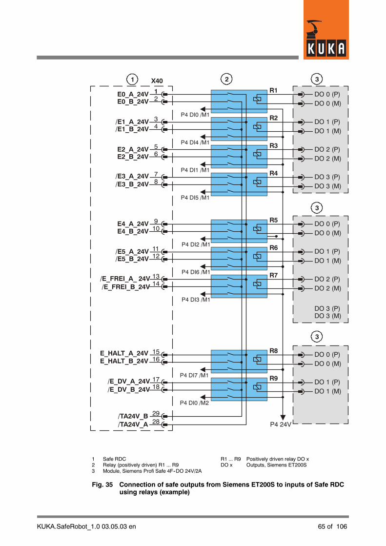
KUKA.SafeRobot_1.0 03.05.03 en 65 of 106
DO 0 (P)
DO 0 (P)
DO 0 (P)
DO 1 (P)
DO 1 (P)
DO 1 (P)
DO 2 (P)
DO 2 (P)
DO 3 (P)
DO 3 (P)
E0_A_24V
E4_A_24V
E_HALT_A_24VE_HALT_B_24V
/TA24V_B
/E1_A_24V
/E5_A_24V
/E_DV_A_24V/E_DV_B_24V
E2_A_24V
/E_FREI_A_ 24V
/E3_A_24V
DO 0 (M)
DO 0 (M)
DO 0 (M)
DO 1 (M)
DO 1 (M)
DO 1 (M)
DO 2 (M)
DO 2 (M)
DO 3 (M)
DO 3 (M)
E0_B_24V
E4_B_24V
/TA24V_A
/E1_B_24V
/E5_B_24V
E2_B_24V
/E_FREI_B_24V
/E3_B_24V
P4 DI0 /M1
P4 DI2 /M1
P4 DI7 /M1
P4 DI4 /M1
P4 DI6 /M1
P4 DI0 /M2
P4 DI1 /M1
P4 DI3 /M1
P4 DI5 /M1
R1
R2
R3
R4
P4 24V
1 2 3
3
3
1
3
5
7
2
4
6
8
R81516
R917
29
18
28
R5
R6
R7
9
11
13
10
12
14
X40
1 Safe RDC R1 ... R9 Positively driven relay DO x2 Relay (positively driven) R1 ... R9 DO x Outputs, Siemens ET200S3 Module, Siemens Profi Safe 4F--DO 24V/2A
Fig. 35 Connection of safe outputs from Siemens ET200S to inputs of Safe RDCusing relays (example)
66 of 106 KUKA.SafeRobot_1.0 03.05.03 en
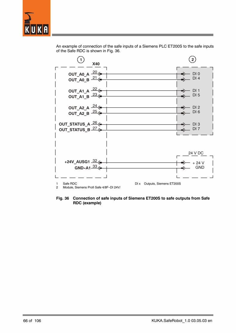
An example of connection of the safe inputs of a Siemens PLC ET200S to the safe inputsof the Safe RDC is shown in Fig. 36.
DI 0
DI 1
DI 2
DI 3
DI 3
OUT_A0_A
OUT_A1_A
OUT_A2_A
+24V_AUSG1
OUT_STATUS_AOUT_STATUS_B
OUT_A0_B
OUT_A1_B
OUT_A2_B
GND--A1
DI 4
DI 5
DI 6
DI 7
DI 7+ 24 VGND
24 V DC
20
22
24
26
32
21
23
25
27
33
1 2X40
1 Safe RDC DI x Outputs, Siemens ET200S2 Module, Siemens Profi Safe 4/8F--DI 24V/
Fig. 36 Connection of safe inputs of Siemens ET200S to safe outputs from SafeRDC (example)

KUKA.SafeRobot_1.0 03.05.03 en 67 of 106
4.7 Assignment of X40 for operation without a PLC
When the “KUKA.SafeRDC” is operated without a safety PLC, the interface X40 of the SafeRDC must be connected as shown in Fig. 37.
GND--A1
GND--P
33
35
GND--E
+24V_AUSG1
GND--P
+24V--P
30
32
31
34
X40
1
GND--A1
GND--P
33
35
GND--E
+24V_AUSG1
GND--P
+24V--P
30
32
31
34
X40
1
1 Safe RDC
Fig. 37 Pin assignment for X40 Safe RDC for operation without a PLC
68 of 106 KUKA.SafeRobot_1.0 03.05.03 en
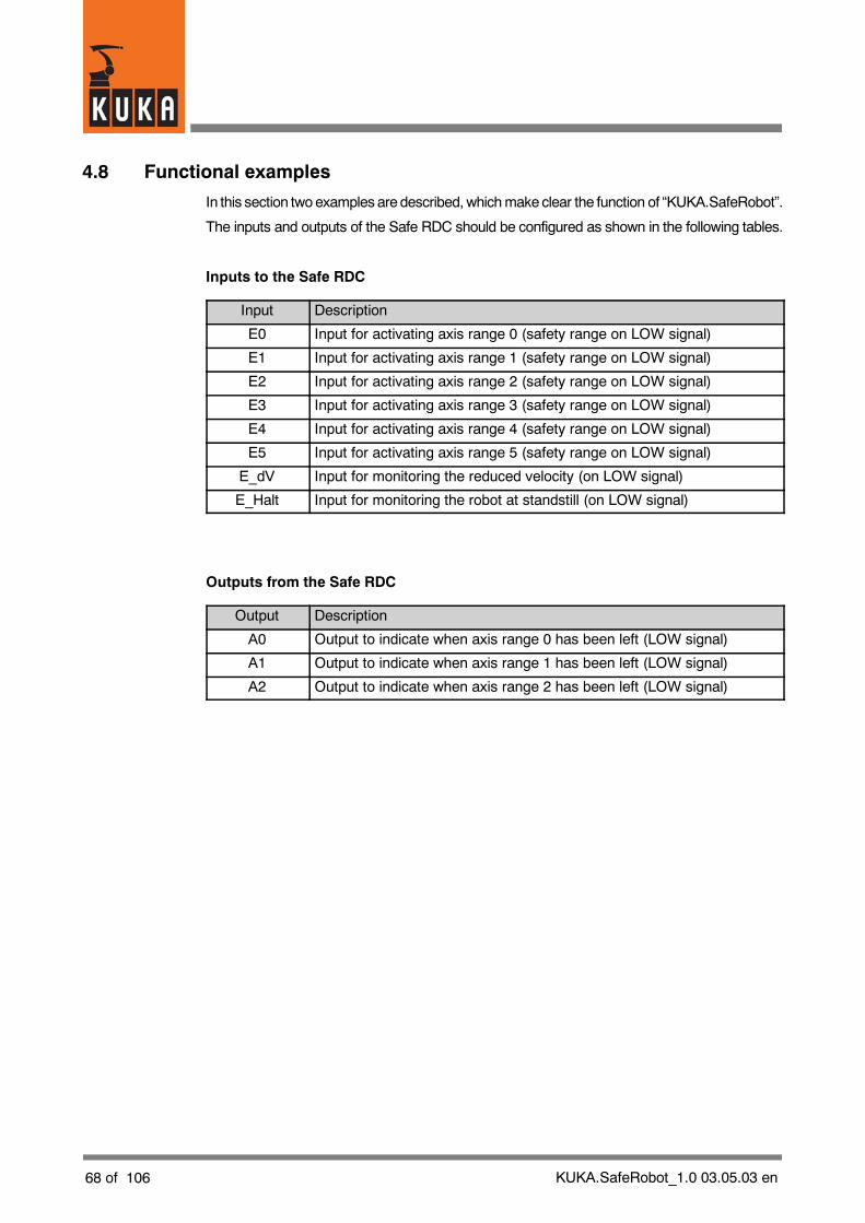
4.8 Functional examples
In this section twoexamples are described, whichmakeclear the function of “KUKA.SafeRobot”.
The inputs and outputs of the Safe RDC should be configured as shown in the following tables.
Inputs to the Safe RDC
Input Description
E0 Input for activating axis range 0 (safety range on LOW signal)
E1 Input for activating axis range 1 (safety range on LOW signal)
E2 Input for activating axis range 2 (safety range on LOW signal)
E3 Input for activating axis range 3 (safety range on LOW signal)
E4 Input for activating axis range 4 (safety range on LOW signal)
E5 Input for activating axis range 5 (safety range on LOW signal)
E_dV Input for monitoring the reduced velocity (on LOW signal)
E_Halt Input for monitoring the robot at standstill (on LOW signal)
Outputs from the Safe RDC
Output Description
A0 Output to indicate when axis range 0 has been left (LOW signal)
A1 Output to indicate when axis range 1 has been left (LOW signal)
A2 Output to indicate when axis range 2 has been left (LOW signal)

KUKA.SafeRobot_1.0 03.05.03 en 69 of 106
4.8.1 Example of a loading station at a turntable
Fig. 38 shows a loading station at a turntable.
1
2
3
1 Robot
2 Turntable
3 Safeguard (e.g. safety mat)
Fig. 38 Loading station at a turntable
It must be ensured that the robot cannot move into the safety rangeor carry out motionwithinit when the safeguard is triggered (e.g. when a person is standing on the safety mat). Thisis monitored in this example by input E0, which in the example shown is linked to the safetymat (LOW signal).
Fig. 39 shows the individual ranges:
G Working range
G Range with reduced velocity
G Safety range
Fig. 40 shows the connection of the safeguard (e.g. safety mat) to the interface X40 of theSafe RDC and other necessary jumpers.
The rangewith reduced velocity is alsomonitored, so that the safety clearances can be reduced.This is done by connecting output A0 to the input for activating the reduced velocity (E_dV).

70 of 106 KUKA.SafeRobot_1.0 03.05.03 en
Safe RDCE0E1E2
E_Halt
E3E4E5E_dV
A0A1A2
1
2
3
5
6
4
1 Working range 4 Safeguard (e.g. safety mat)
2 Safety range 5 Range with reduced velocity
3 Turntable 6 Dual channel connection
Fig. 39 Loading station at a turntable -- ranges, inputs, outputs
E0_A_24V
/TA24V_A
E0_B_24V
/TA24V_B
/E_DV_A_24V
/E_DV_B_24V
OUT_A0_A
OUT_A0_B
1
28
2
29
17
18
20
21
X401 2
1 Safe RDC
2 Safeguard (e.g. safety mat)
Fig. 40 Safe RDC, X40 -- connection to safeguard and jumpering

KUKA.SafeRobot_1.0 03.05.03 en 71 of 106
4.8.2 Example of a loading station at a robot gripper
Fig. 41 shows a loading station at which the component is placed manually directly into therobot gripper.
12
3
1 Robot
2 Robot gripper
3 Safeguard (e.g. safety mat)
Fig. 41 Loading station at a robot gripper
Fig. 42 shows the individual ranges:
G Working range
G Range with reduced velocity
G Safety range
Fig. 43 shows the connection of the safeguard (e.g. safety mat) to the interface X40 of theSafe RDC and other necessary jumpers.
It must be ensured that if the robot is in the safety range it does not move after the safeguardhas been triggered (e.g. after the safety mat has been stepped on). This is monitored in thisexample by input E_Halt, which is linked to the safety mat (LOW signal).
The rangewith reduced velocity is alsomonitored, so that the safety clearances can be reduced.This is done by connecting output A0 to the input for activating the reduced velocity (E_dV).

72 of 106 KUKA.SafeRobot_1.0 03.05.03 en
Safe RDCE0E1E2
E_Halt
E3E4E5E_dV
A0A1A2
1
2
3
5
6
4
1 Working range 4 Safeguard (e.g. safety mat)
2 Safety range 5 Range with reduced velocity
3 Robot gripper 6 Dual channel connection
Fig. 42 Loading station at a robot gripper -- ranges, inputs, outputs
E_HALT_A_24V
/TA24V_A
E_HALT_B_24V
/TA24V_B
/E_DV_A_24V
/E_DV_B_24V
OUT_A0_A
OUT_A0_B
1
28
2
29
17
18
20
21
X401 2
1 Safe RDC
2 Safeguard (e.g. safety mat)
Fig. 43 Safe RDC, X40 -- connection to safeguard and jumpering

KUKA.SafeRobot_1.0 03.05.03 en 73 of 106
5 Commissioning
5.1 Prerequisites
5.1.1 Requirements regarding the operating personnel
The following instructions and information must be observed in order to ensure the safetyof the operating personnel, third parties and the overall installation.
In case of doubt regarding the order in which to carry out different procedures,human safety is to be the overriding consideration that determines the sequencefollowed.
G Operating personnelmust be thoroughly instructed in the handling and operation of theequipment, either by the user or by a person entrusted with this task by the user.
G Set--up, installation, configuration, operation, programming, exchange andmaintenance / repair must be performed only by personnel specially trained for theproduct described here.
5.1.2 Instruction and training of operating personnel
The basis for the instruction of the operating personnel is these operating instructions.
We recommend suitable training for the operating personnel.
Information on training courses is available from the addresses listed in Section 1.1.
5.1.3 Training for administrators and safety maintenance personnel
For persons with access to the user groups “Administrators” and “Safety maintenance”appropriate training is necessary.
Information on training courses is available from the addresses listed in Section 1.1.
74 of 106 KUKA.SafeRobot_1.0 03.05.03 en
5.2 Installing the configuration program
The installation, uninstallation, reinstallation and update of technology packages are describedin detail in the documentation [Installation/Uninstallation/Update of Tech Packages].
5.3 Using the configuration program
5.3.1 User group
For configuration and parameterization a dedicated configuration program is available. Touse this program it is necessary to have the appropriate user rights.
This requires
G Logging into the appropriate user group by means of the menu function“Configuration”! “User group”.In the window which opens, select the option “Safety maintenance” under “Choose auser:” and enter the password in the corresponding box. See also information andinstructions on the HMI screen.
G Setting the operating mode “T1” or “T2”
It is essential that users of the robot controller cannot log into the user group“Safety maintenance” and also do not have administrator rights, becauseotherwise the safety aspects of user administration in the robot controller wouldbe compromised!
If the login is not to the user group “Safety maintenance” the parameters can still beviewed, but not changed.
KUKA.SafeRobot_1.0 03.05.03 en 75 of 106
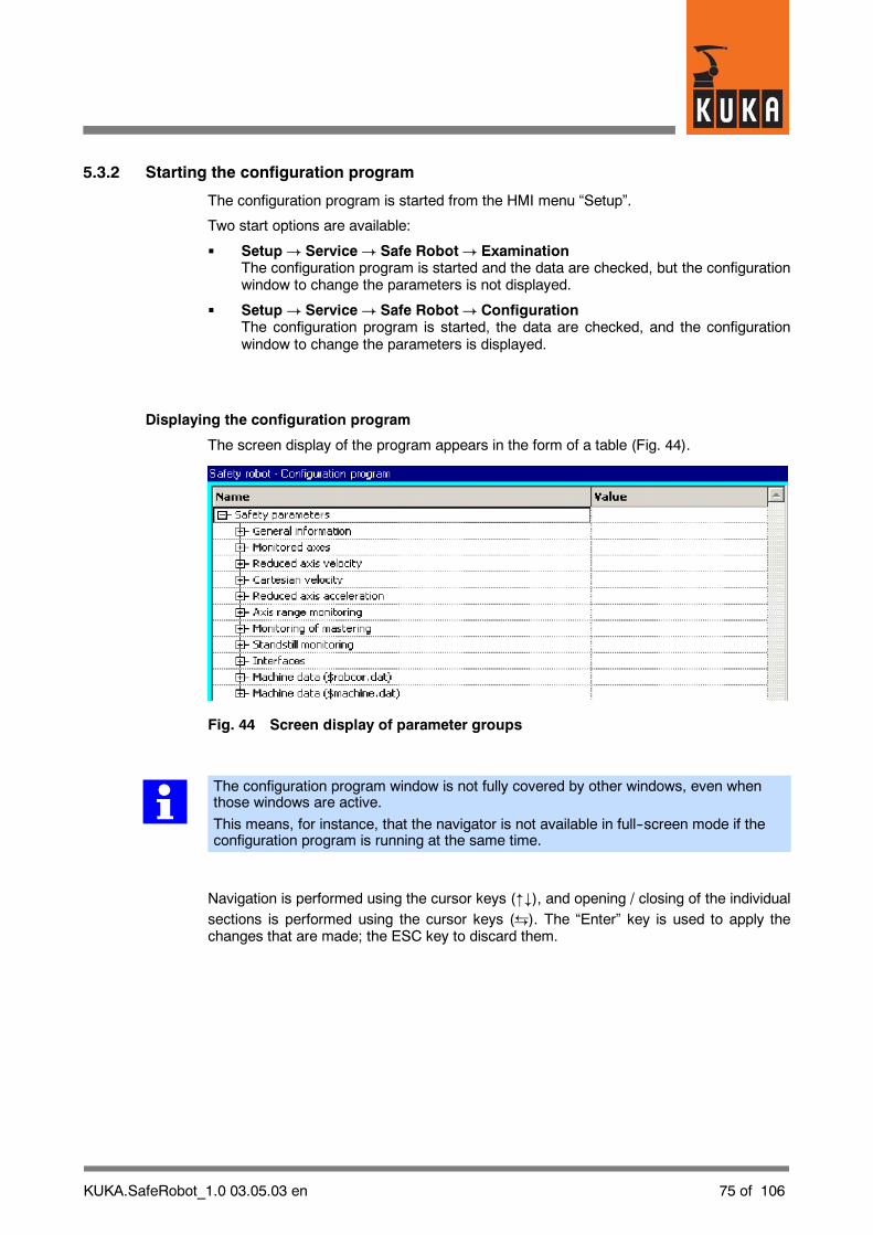
5.3.2 Starting the configuration program
The configuration program is started from the HMI menu “Setup”.
Two start options are available:
G Setup ! Service! Safe Robot! ExaminationThe configuration program is started and the data are checked, but the configurationwindow to change the parameters is not displayed.
G Setup ! Service! Safe Robot! ConfigurationThe configuration program is started, the data are checked, and the configurationwindow to change the parameters is displayed.
Displaying the configuration program
The screen display of the program appears in the form of a table (Fig. 44).
Fig. 44 Screen display of parameter groups
The configuration program window is not fully covered by other windows, even whenthose windows are active.
This means, for instance, that the navigator is not available in full--screen mode if theconfiguration program is running at the same time.
Navigation is performed using the cursor keys ("#), and opening / closing of the individualsections is performed using the cursor keys ({). The “Enter” key is used to apply thechanges that are made; the ESC key to discard them.

76 of 106 KUKA.SafeRobot_1.0 03.05.03 en
After the program has been started the necessary data records are read in. This is indicatedby a message on the screen.
The RDC data are read in only if the data saved on the hard disk are identical withthose saved in the RDC.
The format version of the data is compatible with the RDC software and has a fixed link to it.
NOTELoading and saving procedures should not be interrupted.
If an error occurs, the procedure will be aborted.This is indicated by an error message.
5.3.3 Checking the data
When the robot controller is booted up a check is made to discover whether the software onthe Safe RDC is the current version. If the software version on the Safe RDC is an olderversion than that in the controller, the current version will be loaded to the Safe RDC.
After reading in the data, the data saved on the hard disk are compared with the data in theRDC. If they are identical, the data are loaded into the configuration table.
If the data are different, the user must decide which data records to use.
If the RDC data are invalid or incompatible, only the data on the hard disk can be loaded.
When data are loaded from the hard disk or from the RDC, all of the respective para-meters are loaded into the configuration table.When machine data are loaded, only the data from the machine data file are loaded.
If an error occurs, the execution of the program is aborted; this is indicated by an errormessage.
NOTERuntime variables are only stored internally (volatile memory) and not on the hard diskor in the RDC table.
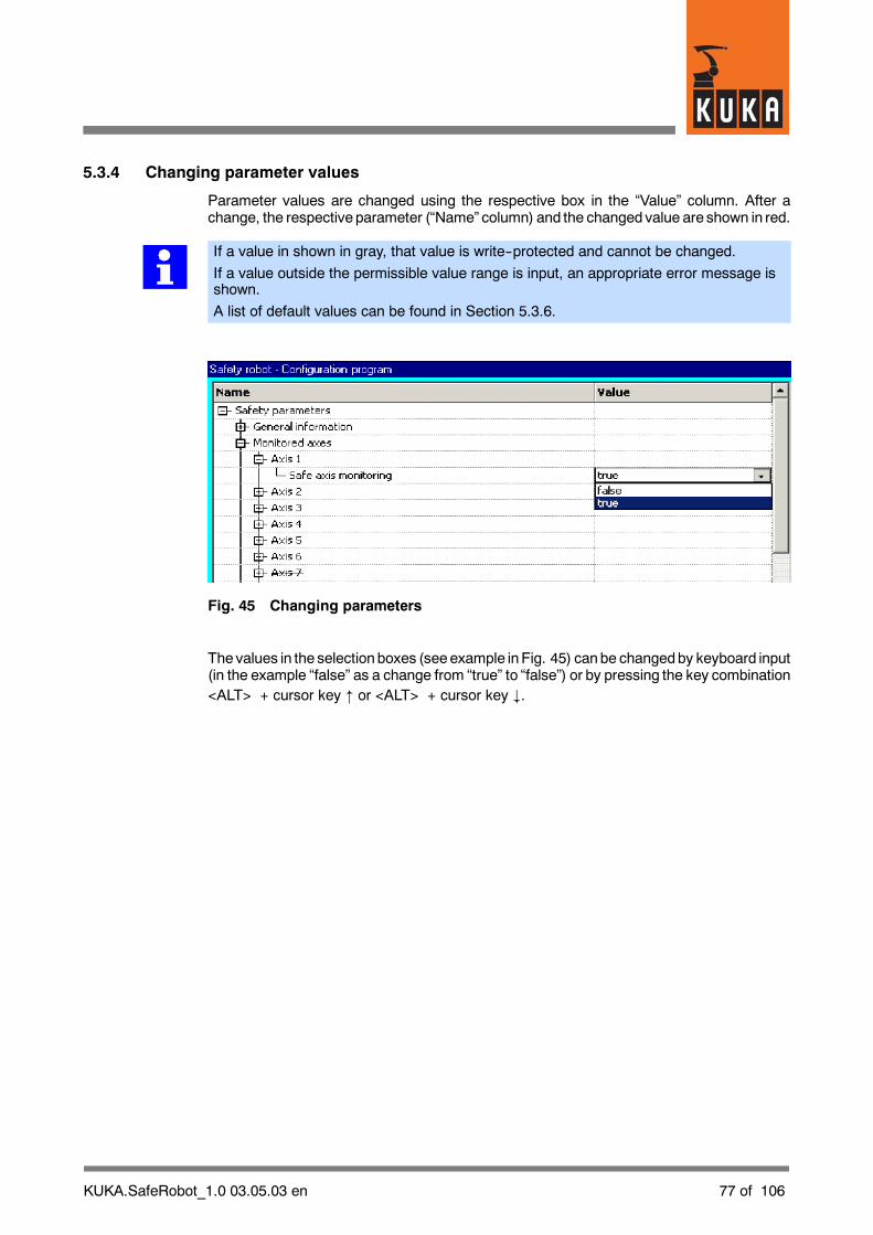
KUKA.SafeRobot_1.0 03.05.03 en 77 of 106
5.3.4 Changing parameter values
Parameter values are changed using the respective box in the “Value” column. After achange, the respective parameter (“Name” column) and the changedvalue are shown in red.
If a value in shown in gray, that value is write--protected and cannot be changed.
If a value outside the permissible value range is input, an appropriate error message isshown.
A list of default values can be found in Section 5.3.6.
Fig. 45 Changing parameters
Thevalues in the selection boxes (seeexample inFig. 45) canbe changedby keyboard input(in the example “false” as a change from “true” to “false”) or by pressing the key combination<ALT> + cursor key " or <ALT> + cursor key #.

78 of 106 KUKA.SafeRobot_1.0 03.05.03 en
To quit the configuration program, press the softkey “Close”. If changes have been made,you will be asked whether these changes should be saved. Press the softkey “Yes” to savethe changes and close the configuration program. Press the softkey “No” to close theprogram without saving the changed values. Press the softkey “Cancel” to return to theconfiguration program.
5.3.5 Configuration of safety--relevant parameters
The configuration program allows safety parameters to be configured.
Safety--relevant parameters are:
G Axis velocity [_/s]
G Axis acceleration [_/s2]
G Safe reduced velocity [mm/s]
G Reference point (position of all axes) [_]
G Axis range limits [_] (radial axes)
G Axis range limits [mm] (linear axes)
G Activation/deactivation of the test pulses for the inputs
There follows a description of the safety--relevant parameters in the order that they appearin the configuration program.
General information
The section “General information” (Fig. 46) shows the content of the time stamp and theversion. These values cannot be edited.
Fig. 46 General information

KUKA.SafeRobot_1.0 03.05.03 en 79 of 106
Monitored axes
In the section “Monitored axes” (Fig. 47) the monitored axes (A 1 ... A 8) are entered.
Fig. 47 Monitored axes
Axes to bemonitored are set to the value “true”, axes not to be monitored are set to the value“false”.
Thenamesof axes that are not to bemonitoredare showncrossedout in the “Name” column.
Reduced axis velocity
In the section “Reduced axis velocity” (Fig. 48) an axis velocity differing from the defaultvalue (see Section 5.3.6) can be entered.
Fig. 48 Reduced axis velocity
Cartesian velocity
In the section “Cartesian velocity” (Fig. 49) the Cartesian axis velocity (flange center point)can be changed.
Fig. 49 Cartesian velocity
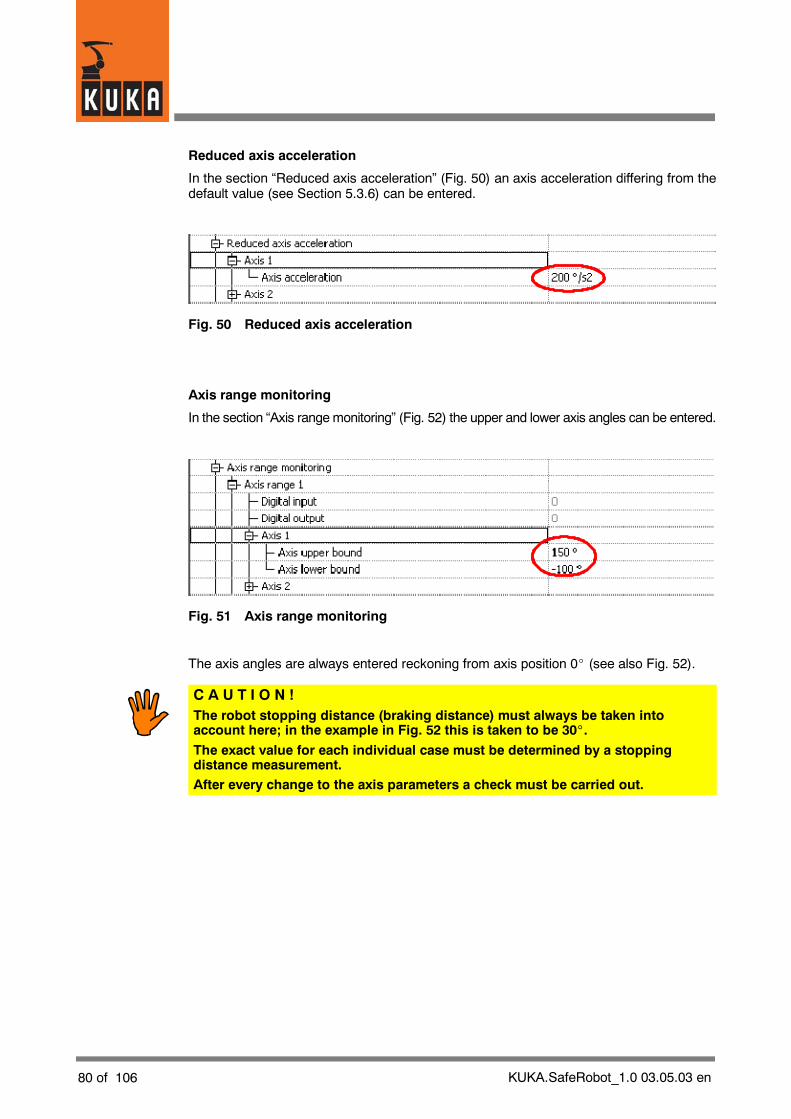
80 of 106 KUKA.SafeRobot_1.0 03.05.03 en
Reduced axis acceleration
In the section “Reduced axis acceleration” (Fig. 50) an axis acceleration differing from thedefault value (see Section 5.3.6) can be entered.
Fig. 50 Reduced axis acceleration
Axis range monitoring
In the section “Axis rangemonitoring” (Fig. 52) the upper and lower axis angles can be entered.
Fig. 51 Axis range monitoring
The axis angles are always entered reckoning from axis position 0_ (see also Fig. 52).
C A U T I O N !The robot stopping distance (braking distance) must always be taken intoaccount here; in the example in Fig. 52 this is taken to be 30_.
The exact value for each individual case must be determined by a stoppingdistance measurement.After every change to the axis parameters a check must be carried out.
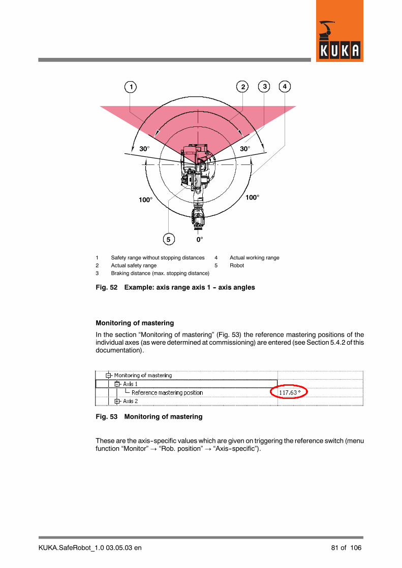
KUKA.SafeRobot_1.0 03.05.03 en 81 of 106
30° 30°
0°
100°100°
5
1 2 3 4
1 Safety range without stopping distances 4 Actual working range
2 Actual safety range 5 Robot
3 Braking distance (max. stopping distance)
Fig. 52 Example: axis range axis 1 -- axis angles
Monitoring of mastering
In the section “Monitoring of mastering” (Fig. 53) the reference mastering positions of theindividual axes (as were determined at commissioning) are entered (see Section 5.4.2 of thisdocumentation).
Fig. 53 Monitoring of mastering
These are the axis--specific values which are given on triggering the reference switch (menufunction “Monitor”! “Rob. position”! “Axis--specific”).

82 of 106 KUKA.SafeRobot_1.0 03.05.03 en
Standstill monitoring -- Axis angle tolerance
In the section “Standstill monitoring” (Fig. 54) an axis angle tolerance differing from thedefault value (see Section 5.3.6) can be entered for the respective axis.
Fig. 54 Standstill monitoring -- Axis angle tolerance
Interfaces -- Input check pulsing
In the section “Interfaces” (Fig. 55) the value for “Input check pulsing” can be set to “true”or “false”.
Fig. 55 Interfaces -- Input check pulsing

KUKA.SafeRobot_1.0 03.05.03 en 83 of 106
Machine data
In the section “Machine data” (Fig. 56) the machine data from “$robcor.dat” and“$machine.dat” can be viewed but not changed.
Fig. 56 Machine data
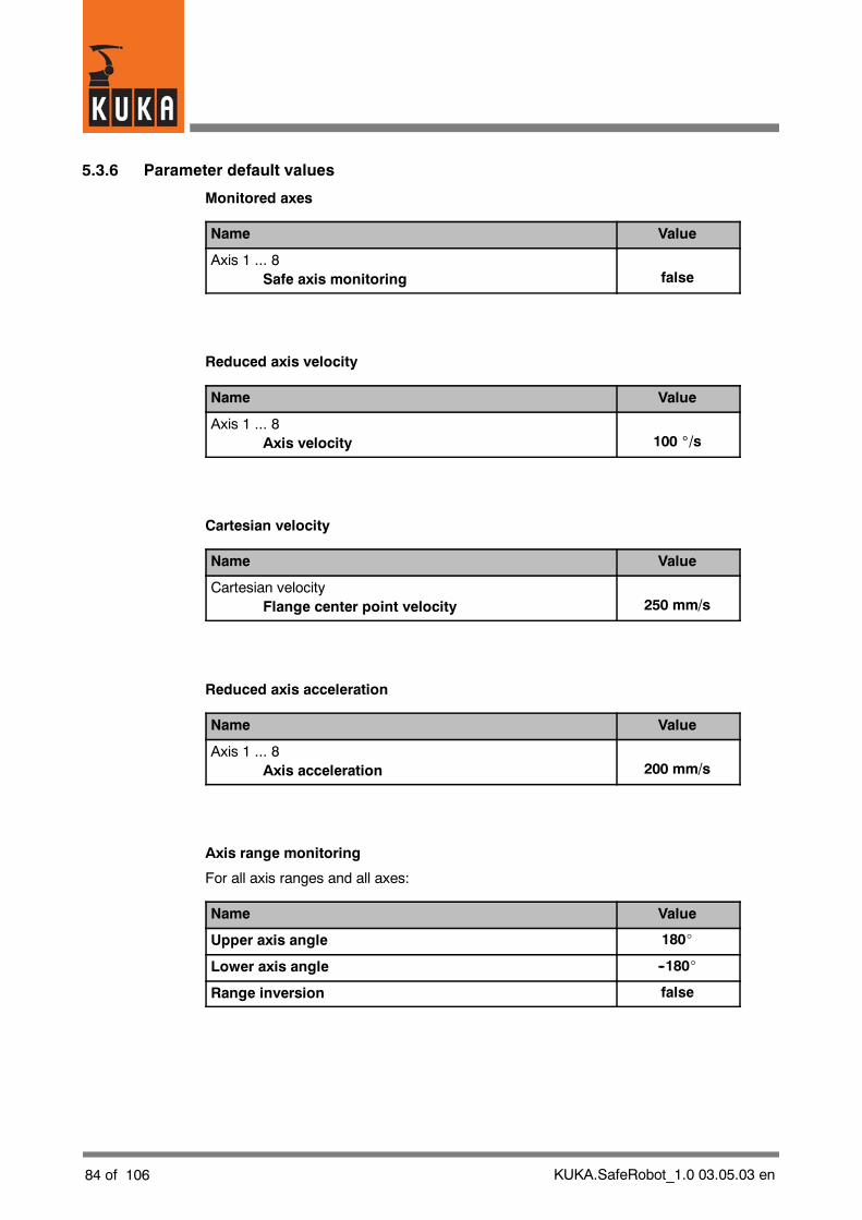
84 of 106 KUKA.SafeRobot_1.0 03.05.03 en
5.3.6 Parameter default values
Monitored axes
Name Value
Axis 1 ... 8Safe axis monitoring false
Reduced axis velocity
Name Value
Axis 1 ... 8Axis velocity 100 _/s
Cartesian velocity
Name Value
Cartesian velocityFlange center point velocity 250 mm/s
Reduced axis acceleration
Name Value
Axis 1 ... 8Axis acceleration 200 mm/s
Axis range monitoring
For all axis ranges and all axes:
Name Value
Upper axis angle 180_
Lower axis angle --180_
Range inversion false
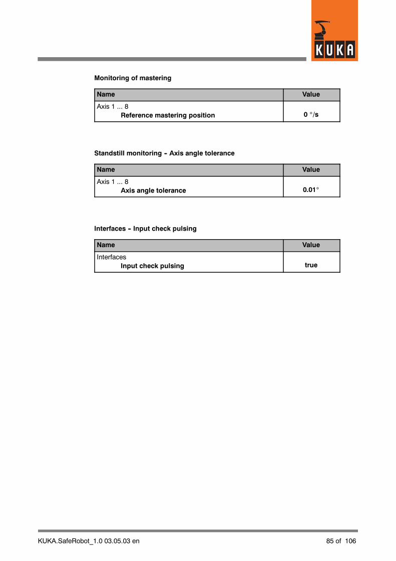
KUKA.SafeRobot_1.0 03.05.03 en 85 of 106
Monitoring of mastering
Name Value
Axis 1 ... 8Reference mastering position 0 _/s
Standstill monitoring -- Axis angle tolerance
Name Value
Axis 1 ... 8Axis angle tolerance 0.01_
Interfaces -- Input check pulsing
Name Value
InterfacesInput check pulsing true

86 of 106 KUKA.SafeRobot_1.0 03.05.03 en
5.4 Brake test and reference run
W A R N I N G !While the drives are being disconnected, no person should be within the robotrange, because it is not impossible the robot may sag!
5.4.1 Brake test
For assurance of the braking function of the robot axes, after every boot--up of the robotcontroller and at intervals of every eight hours when the robot is operating a brake testmust be performed.
NOTEThe brake test cannot be performed in “T1” mode.
If the test is not performed in time or is unsuccessful a message appears to this effect in theKCP message window.
W A R N I N G !The robot can continue to operate and execute its program after a brake test hasbeen omitted or failed, but it is no longer in a safe condition and this can pose ahazard to persons and property!
The brake test is activated by calling a function in a KRL program. This is done by creatinga KRL sub--function, which is integrated into a KRL program. A program example is includedin Section 7.1 of this documentation.
The brake test is performedon eachaxis successively. The robotmoves at a defined velocityand the brakes are applied. During this process the respective motor current is monitored.A message is displayed based on the measured value of the current.
After successful completion of the test on all axes, the message “Ackn. brake test re-quired” is displayed in the message window of the KCP.
C A U T I O N !In the event of a brake failure the robot should be brought into a gravity--neutralposition, to reduce the risk of uncontrolled movements resulting from theabsence of braking.Please contact your KUKA Service Center to initiate repairs.

KUKA.SafeRobot_1.0 03.05.03 en 87 of 106
5.4.2 Reference run
To check the robot mastering, after every boot--up of the robot controller and at intervalsof every eight hours when the robot is operating a reference run must be performed.
For this purpose the robot is moved to a defined reference position where it actuates thereference switch. At this reference position the actual values of the axes must correspondto the reference setpoint values. To move to the reference position, a movement to an exactpositioning point is programmed, so that the robot moves to precisely the desired position.
If the test is not performed in time or is unsuccessful a message appears to this effect in theKCP message window.
W A R N I N G !The robot can continue to operate and execute its program after a reference runhas been omitted or failed, but it is no longer in a safe condition and this canpose a hazard to persons and property!
For information about the reference switch and its installation, see Section 4.4 of thisdocumentation. A program example is included in Section 7.1 of this documentation.
The followingactions should beperformedat commissioningor if it is necessary to determinethe reference values:
G Move the actuating plate mounted on the robot wrist towards the sensors on thereference switch (identified by the two green dots on the face of the reference switch).The distance between the reference switch and actuating platemust be between 2 and3 mm.
G When theactuating plate is correctly positionedover the reference switch, the twoLEDson the underside of the reference switch light up.
G Teach this position and name the point “RefSwitch”.
G Using the menu function “Monitor”! “Rob. position”! “Axis--specific” open the statuswindow and make a note of the axis--specific values.
G Move the robot to the home position.
G Start the configuration program using the menu functionSetup! Service! Safe Robot! Configuration (see Section 5.3.2).
G Under “Monitoring of mastering” enter the values previously noted, and save them.
G The next time the robot moves to the reference switch, the values determined for thecurrent robot position are compared with the saved reference values. If the valuesagree, the message “Ackn. mastering test required” is displayed.
88 of 106 KUKA.SafeRobot_1.0 03.05.03 en
5.5 Acceptance test for KUKA.SafeRobot -- Checklist
It is a pre--requirement for commissioning that an acceptance test shall have beenperformedfor the system in accordance with the checklist shown in Section 10.2.
KUKA.SafeRobot_1.0 03.05.03 en 89 of 106
6 Operation
6.1 Safe robot retraction
“Safe retraction” mode is activated by setting the safe input “Safe retraction” using thekeyswitch. See Section 4.5. When safe retraction is activated a corresponding message isdisplayed.
In “safe retraction” mode the Cartesian velocity monitoring, the axis--specific velocitymonitoring and the axis--specific acceleration monitoring are all activated. All othermonitoring is deactivated, so that the robot can be moved free out of an interlocked range.
C A U T I O N !In this operating mode the robot cannot be monitored in safe mode.Because safe retraction compromises the safety of the robot, this must beperformed only by authorized personnel using a safe input.
90 of 106 KUKA.SafeRobot_1.0 03.05.03 en
KUKA.SafeRobot_1.0 03.05.03 en 91 of 106
7 Programming
7.1 Brake test and reference run
Brake tests and reference runs must be performed every time the robot controller is bootedup, and also at specified intervals during continuous operation. See Section 5.4.
Program examples for extending the “SPS.SUB” program and the KRL program (*.src) canbe found in Sections 7.1.1 and 7.1.2.
As well as these extensions, some additional user--defined variablesmust be declared in thefile “$CONFIG.DAT” (directory “C:\KRC\ROBOTER\KRC\steu”), in the section“User--defined Variables”:
;==================================; Userdefined Variables;==================================
BOOL boRef=FALSE
BOOL boRefDone=FALSE
BOOL boBrakeTest=FALSE
BOOL boBrakeTestDone=FALSE
BOOL boReboot=FALSE
;==================================
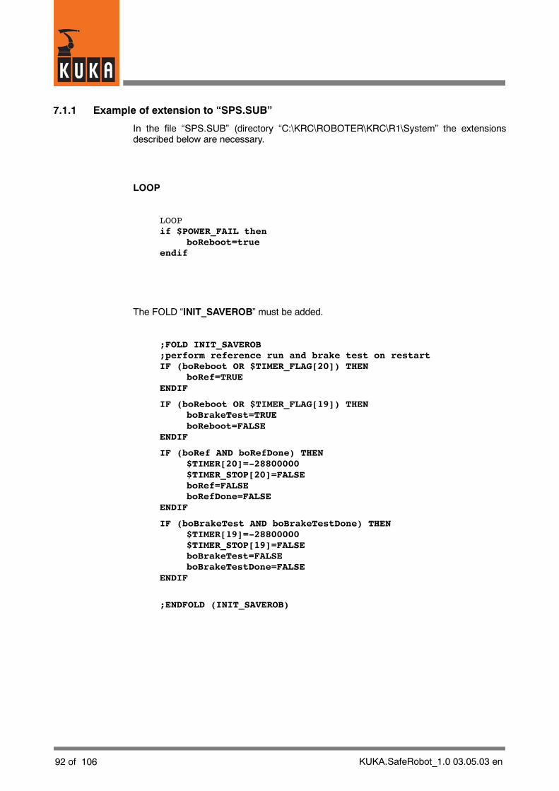
92 of 106 KUKA.SafeRobot_1.0 03.05.03 en
7.1.1 Example of extension to “SPS.SUB”
In the file “SPS.SUB” (directory “C:\KRC\ROBOTER\KRC\R1\System” the extensionsdescribed below are necessary.
LOOP
LOOPif $POWER_FAIL then
boReboot=trueendif
The FOLD “INIT_SAVEROB” must be added.
;FOLD INIT_SAVEROB;perform reference run and brake test on restartIF (boReboot OR $TIMER_FLAG[20]) THEN
boRef=TRUEENDIF
IF (boReboot OR $TIMER_FLAG[19]) THENboBrakeTest=TRUEboReboot=FALSE
ENDIF
IF (boRef AND boRefDone) THEN$TIMER[20]=-28800000$TIMER_STOP[20]=FALSEboRef=FALSEboRefDone=FALSE
ENDIF
IF (boBrakeTest AND boBrakeTestDone) THEN$TIMER[19]=-28800000$TIMER_STOP[19]=FALSEboBrakeTest=FALSEboBrakeTestDone=FALSE
ENDIF
;ENDFOLD (INIT_SAVEROB)

KUKA.SafeRobot_1.0 03.05.03 en 93 of 106
7.1.2 Example of extension to a KRL program
To perform brake tests and reference runs automatically at the required intervals of time, anappropriate command sequence must be inserted into the KRL program.
if boRef thenRefschalter( )boRefDone=true
endif
if boBrakeTest thenbrakeTest(0 )boBrakeTestDone=true
endif
Program example for reference run
; Movement to within approx. 10 cm of the reference switchPTP P1 Vel= 100 % PDAT1 Tool[1] Base[0]
; Precise movement to the reference switchLIN REFSCHALTER Vel= 0.5 m/s CPDAT1 Tool[1] Base[0]
; Movement away from the reference switchLIN P1 VEL= 0.5 m/s CPDAT2 Tool[1] Base[0]
NOTE:When programming the reference run, note that the movement to the reference switchand the movement back from it are not executed as PTP motions.

94 of 106 KUKA.SafeRobot_1.0 03.05.03 en
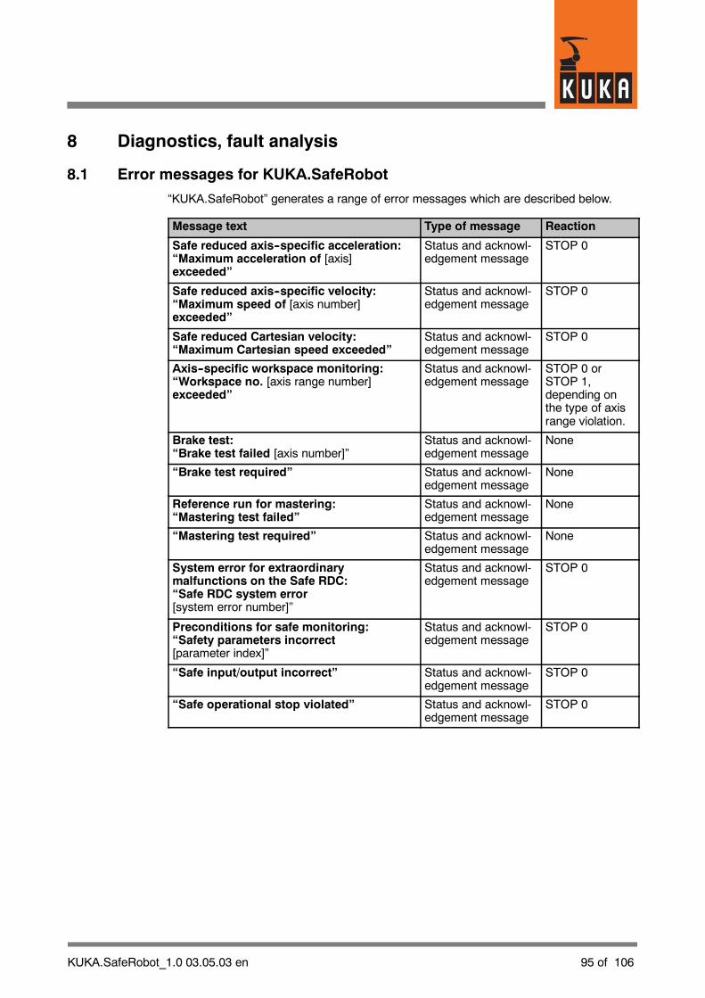
KUKA.SafeRobot_1.0 03.05.03 en 95 of 106
8 Diagnostics, fault analysis
8.1 Error messages for KUKA.SafeRobot
“KUKA.SafeRobot” generates a range of error messages which are described below.
Message text Type of message Reaction
Safe reduced axis--specific acceleration:“Maximum acceleration of [axis]exceeded”
Status and acknowl-edgement message
STOP 0
Safe reduced axis--specific velocity:“Maximum speed of [axis number]exceeded”
Status and acknowl-edgement message
STOP 0
Safe reduced Cartesian velocity:“Maximum Cartesian speed exceeded”
Status and acknowl-edgement message
STOP 0
Axis--specific workspace monitoring:“Workspace no. [axis range number]exceeded”
Status and acknowl-edgement message
STOP 0 orSTOP 1,depending onthe type of axisrange violation.
Brake test:“Brake test failed [axis number]”
Status and acknowl-edgement message
None
“Brake test required” Status and acknowl-edgement message
None
Reference run for mastering:“Mastering test failed”
Status and acknowl-edgement message
None
“Mastering test required” Status and acknowl-edgement message
None
System error for extraordinarymalfunctions on the Safe RDC:“Safe RDC system error[system error number]”
Status and acknowl-edgement message
STOP 0
Preconditions for safe monitoring:“Safety parameters incorrect[parameter index]”
Status and acknowl-edgement message
STOP 0
“Safe input/output incorrect” Status and acknowl-edgement message
STOP 0
“Safe operational stop violated” Status and acknowl-edgement message
STOP 0
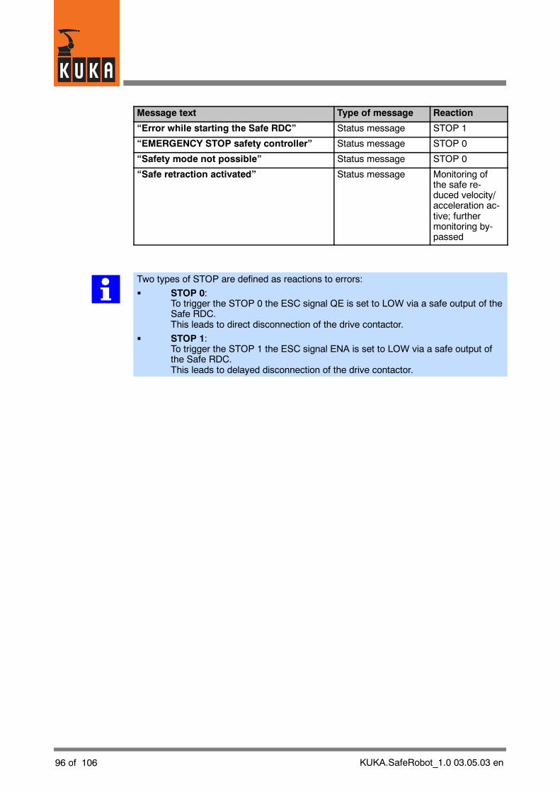
96 of 106 KUKA.SafeRobot_1.0 03.05.03 en
Message text Type of message Reaction
“Error while starting the Safe RDC” Status message STOP 1
“EMERGENCY STOP safety controller” Status message STOP 0
“Safety mode not possible” Status message STOP 0
“Safe retraction activated” Status message Monitoring ofthe safe re-duced velocity/acceleration ac-tive; furthermonitoring by-passed
Two types of STOP are defined as reactions to errors:
G STOP 0:To trigger the STOP 0 the ESC signal QE is set to LOW via a safe output of theSafe RDC.This leads to direct disconnection of the drive contactor.
G STOP 1:To trigger the STOP 1 the ESC signal ENA is set to LOW via a safe output ofthe Safe RDC.This leads to delayed disconnection of the drive contactor.

KUKA.SafeRobot_1.0 03.05.03 en 97 of 106
9 RepairThe specified service life of the hardware used for “KUKA.SafeRobot” is 40,000 operatinghours.
“KUKA.SafeRobot” components should be exchanged no later than at the expiry of thisperiod of time (as shown on the operating hours counter).
9.1 Preparation
W A R N I N G !All pertinent safety regulations as well as the chapter [Safety, General] must beobserved when performing any of the work described below.
Before the start of work the main switch on the control cabinet must be switchedoff and locked with a suitable lock to prevent it being switched back on! Theincoming power cable must be deenergized and measures must be taken toprevent it from being inadvertently energized again.
ON
OFF
Fig. 57 Main switch in the “OFF” position and locked
C A U T I O N !The RDC data cable may not be disconnected while energized!It is essential to wait until completion of the battery backup operation.
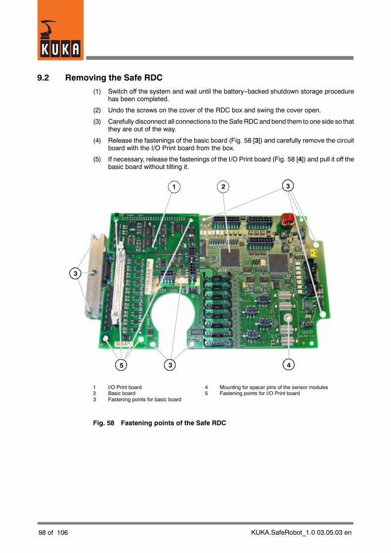
98 of 106 KUKA.SafeRobot_1.0 03.05.03 en
9.2 Removing the Safe RDC
(1) Switch off the system and wait until the battery--backed shutdown storage procedurehas been completed.
(2) Undo the screws on the cover of the RDC box and swing the cover open.
(3) Carefully disconnect all connections to the Safe RDCandbend them to one side so thatthey are out of the way.
(4) Release the fastenings of the basic board (Fig. 58 [3]) and carefully remove the circuitboard with the I/O Print board from the box.
(5) If necessary, release the fastenings of the I/O Print board (Fig. 58 [4]) and pull it off thebasic board without tilting it.
3
3
435
1 2
1 I/O Print board 4 Mounting for spacer pins of the sensor modules2 Basic board 5 Fastening points for I/O Print board3 Fastening points for basic board
Fig. 58 Fastening points of the Safe RDC

KUKA.SafeRobot_1.0 03.05.03 en 99 of 106
9.3 Installing the Safe RDC
(1) Plug the I/O Print board on to the new basic board and tighten the fastening screws(Fig. 58 [4]).
(2) Install the Safe RDC and fasten it into place (Fig. 58 [3]).
(3) Reconnect all connections.
The cables are labeled.If there are no external axes, connectors X7 and X8 (Fig. 18) are not used.

100 of 106 KUKA.SafeRobot_1.0 03.05.03 en

KUKA.SafeRobot_1.0 03.05.03 en 101 of 106
10 Appendix
10.1 Technical data
In this chapter, only the data specific to the “Safe Robot” system are described.Information regarding the technical data of the control cabinet can be found in the chapter[Technical Data] of the KR C2 Operating Handbook.
The following standards were taken into account for “KUKA.SafeRobot”:
G EN 292--1 and 2
G EN 60204--1
G EN 775
G EN 418
G EN 614--1
G EN 954--1
G EN 55011
G EN 61508
G EN 61000--4--2
G EN 61000--4--3
G EN 61000--4--4
G EN 61000--4--5
G EN 61000--4--6
G EN 61000--4--11
“KUKA.SafeRobot” satisfies Safety Category 3 (SIL 2).
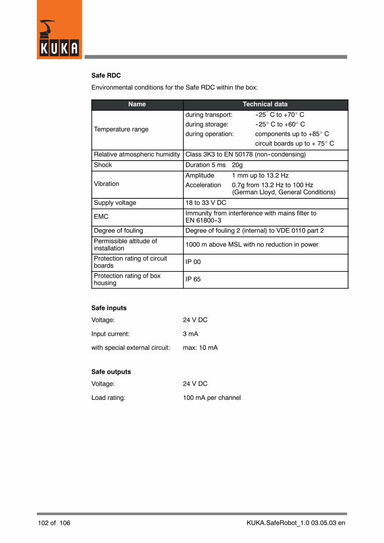
102 of 106 KUKA.SafeRobot_1.0 03.05.03 en
Safe RDC
Environmental conditions for the Safe RDC within the box:
Name Technical data
Temperature range
during transport: --25_C to +70_ C
during storage: --25_ C to +60_ C
during operation: components up to +85_ C
circuit boards up to + 75_ C
Relative atmospheric humidity Class 3K3 to EN 50178 (non--condensing)
Shock Duration 5 ms 20g
VibrationAmplitude 1 mm up to 13.2 Hz
Acceleration 0.7g from 13.2 Hz to 100 Hz(German Lloyd, General Conditions)
Supply voltage 18 to 33 V DC
EMC Immunity from interference with mains filter toEN 61800--3
Degree of fouling Degree of fouling 2 (internal) to VDE 0110 part 2
Permissible altitude ofinstallation 1000 m above MSL with no reduction in power
Protection rating of circuitboards IP 00
Protection rating of boxhousing IP 65
Safe inputs
Voltage: 24 V DC
Input current: 3 mA
with special external circuit: max: 10 mA
Safe outputs
Voltage: 24 V DC
Load rating: 100 mA per channel

KUKA.SafeRobot_1.0 03.05.03 en 103 of 106
10.2 Acceptance test for KUKA.SafeRobot -- Checklists
Before the robot is put into operation, the continuity of the ground conductorconnection between the control cabinet and the robot must be tested with a groundconductor measurement to DIN EN 60204--20.2.
After reinstallation, maintenance work and after every change to the system, thesystem must be subjected to an acceptance test in accordance with the checklists:
-- Robot system check
-- Working range monitoring configuration check
The forms filled in during the checks are to be retained in a secure place as evidence!
NOTEThe system may be put into operation only after successful completion of allchecks.The forms filled in during the checks are to be retained as evidence.
The preconditions for the acceptance test of KUKA.SafeRobot are the completemechanicaland electrical installation of the robot, the controller and thenecessary accessories, togetherwith the correct installation of the software
G KUKA System Software (KSS) Release 5.4
G KUKA.SafeRobot V1.0

104 of 106 KUKA.SafeRobot_1.0 03.05.03 en
Checklist for robot system check
The checks were performed on robot serial number .......................................................
No. Check OK
1 The robot and tool were checked for correct mechanical condition andinstallation.
2 The control cabinet and all its connections were visually checked.
3 All electrical cables were checked for good condition and correctconnection.
4 A check was made to determine whether the entire system (robot,controller, accessories, etc.) satisfied the environmental conditions set out inthe respective specifications.
5 All safeguards (protective fence, light barriers, etc.) were checked for goodcondition and correct operation.
6 The machine data selected were checked and were suitable for the type ofrobot that was connected.
7 A check was made that the actual payload of the robot did not exceed thepermissible payload capacity set out in the specification for the robot.
8 Robot mastering was performed.
9 The reference switch was not in a position which would bring the robot intothe mastering position or a singularity position (see section 4.4.2) whileperforming a reference run (actuation of the reference switch)
10 The external activation of the safe inputs and outputs for the working rangeswas checked for correct operation.
11 The configuration program was opened; if different or incompatible datawere reported, the data were transferred to the Safe RDC.
12 The position of the reference switch was entered in the configurationprogram in axis--specific form.
13 Necessary further configurations were performed in the configurationprogram and transferred to the Safe RDC.
14 The correct configuration of the working ranges were successfully checkedby moving to them. For each working range that was used, the form“Checklist for working range monitoring configuration check” was used andthe respective check successfully performed.
15 Correct configuration of the Cartesian velocity was checked
16 Correct configuration of the axis--specific velocity was checked
17 Correct configuration of the axis--specific acceleration was checked
18 Brake test was performed successfully
19 Reference run was performed successfully
20 Message “Ackn. safety mode not possible” (this message appears when points11, 13, 18 and 19 have been completed successfully)
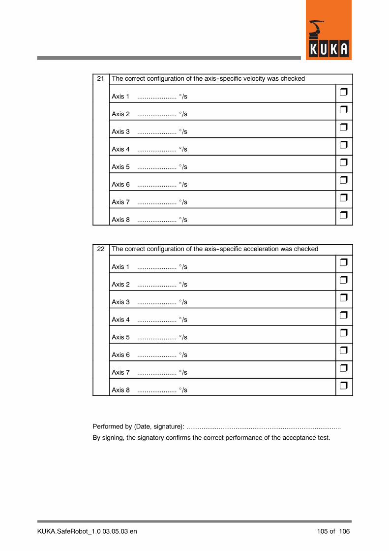
KUKA.SafeRobot_1.0 03.05.03 en 105 of 106
21 The correct configuration of the axis--specific velocity was checked
Axis 1 ..................... _/s
Axis 2 ..................... _/s
Axis 3 ..................... _/s
Axis 4 ..................... _/s
Axis 5 ..................... _/s
Axis 6 ..................... _/s
Axis 7 ..................... _/s
Axis 8 ..................... _/s
22 The correct configuration of the axis--specific acceleration was checked
Axis 1 ..................... _/s
Axis 2 ..................... _/s
Axis 3 ..................... _/s
Axis 4 ..................... _/s
Axis 5 ..................... _/s
Axis 6 ..................... _/s
Axis 7 ..................... _/s
Axis 8 ..................... _/s
Performed by (Date, signature): ..................................................................................
By signing, the signatory confirms the correct performance of the acceptance test.
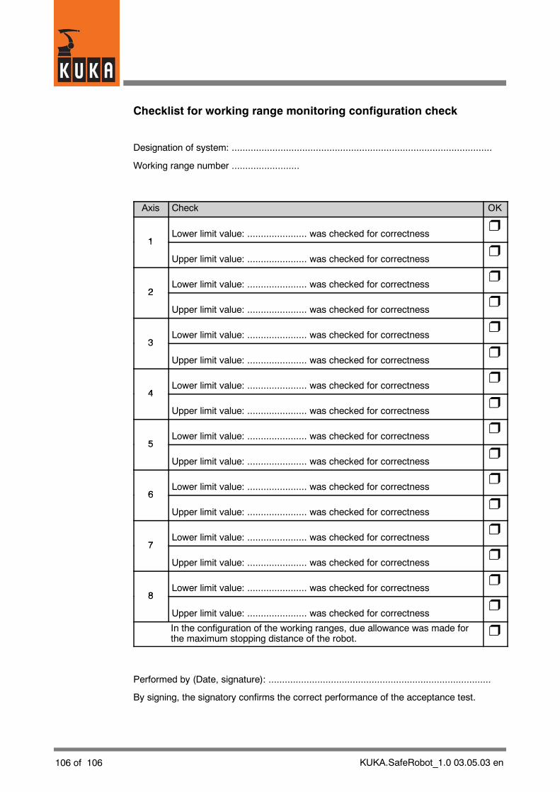
106 of 106 KUKA.SafeRobot_1.0 03.05.03 en
Checklist for working range monitoring configuration check
Designation of system: ................................................................................................
Working range number .........................
Axis Check OK
1Lower limit value: ...................... was checked for correctness
1
Upper limit value: ...................... was checked for correctness
2Lower limit value: ...................... was checked for correctness
2
Upper limit value: ...................... was checked for correctness
3Lower limit value: ...................... was checked for correctness
3
Upper limit value: ...................... was checked for correctness
4Lower limit value: ...................... was checked for correctness
4
Upper limit value: ...................... was checked for correctness
5Lower limit value: ...................... was checked for correctness
5
Upper limit value: ...................... was checked for correctness
6Lower limit value: ...................... was checked for correctness
6
Upper limit value: ...................... was checked for correctness
7Lower limit value: ...................... was checked for correctness
7
Upper limit value: ...................... was checked for correctness
8Lower limit value: ...................... was checked for correctness
8
Upper limit value: ...................... was checked for correctness
In the configuration of the working ranges, due allowance was made forthe maximum stopping distance of the robot.
Performed by (Date, signature): ..................................................................................
By signing, the signatory confirms the correct performance of the acceptance test.
1
Index
Index -- i
A
Acceptance test for KUKA.SafeRobot, 88, 103
Additional safety instructions for “KUKA.Safe-Robot”, 12
Axis angle tolerance, 82, 85
Axis range 1, 20
Axis range monitoring, 84
Axis ranges 2 to 7, 21
B
Basic board, 99
Battery backup, 97
Brake test, 86, 91
Braking distance, 17
Braking reactions, 16
C
Cartesian velocity, 84
Changing parameter values, 77
Checking the data, 76
Checklist, 88, 103
CI 3 technology, 33
Commissioning, 73
Conditions for the safe monitoring of the robot,18
Configuration, 75
Configuration of safety--relevant parameters,78
Configuration program, 74
Connecting cables, 54
Connection panel on the control cabinet (Daim-lerChrysler), 29
Connection panel on the control cabinet (stan-dard), 28
Connection to a safety PLC, 64
Connections to the basic board, 40
Connections to the I/O Print board, 41
Connections to the piggyback board for inputsand outputs, 41
Connections to the Safe RDC board, 40
Connections to the Safe RDC box, 37
Construction standards, 101
Control cabinet components, 30
Control cabinet KR C2 edition2005, 27
D
Defective fuse, 35
Designated use, 13
Digital Servo Electronics, 32
Displaying the configuration program, 75
DSE signals, 51
DSE--IBS, 32
DSP, 38
Dual--channel, 33, 38
E
EMT signals, 45
Environmental conditions for Safe RDC, 102
Error messages, 95
ESC signals, 48, 52
Examination, 75
F
Fastening points of the Safe RDC, 98
Functions, 18
Functions of the Safe RDC, 39
I
I/O Print, 38
If questions or problems arise, 10
Indicators, 42
Input check pulsing, 82, 85
Input for reference switch, 49
Installing the Safe RDC, 99
J
Junction boxes on the robot, 26
K
KRL program, 93
L
Layout, 25
LEDs for microcontrollers, 43
LEDs for safe outputs, 43
LEDs for the DSP, 44
LEDs on Safe RDC, 42

Index
Index -- ii
MMain switch, 97Minimum current, 38Monitored axes, 84Monitoring of mastering, 85, 87Monitoring of robot mastering, 39Monitoring of the safe inputs and outputs, 18Multi--function card MFC 3, 30
PParameter default values, 84Periphery, 64Product description, 15Program example for reference run, 93
RRed LED, 35Reduced axis acceleration, 84Reduced axis velocity, 84Reference run, 87, 91Reference switch, 49, 53, 58Removing the Safe RDC, 98Resistive circuit, 38Resolver evaluation, 39
SSafe axis range monitoring, 20Safe functions, 18Safe inputs, Technical data, 102Safe inputs and outputs, 46Safe operational stop, 23Safe outputs, Technical data, 102Safe position sensing system, 19Safe RDC, 36, 38Safe RDC box, 36Safe reduced velocity, axis--specific, 19Safe reduced velocity, Cartesian, 19Safety, 11Safety bus, 33Safety category of Safe Robot, 101Safety logic, 33Safety maintenance, 74Safety parameters -- Axis range monitoring, 80Safety parameters -- Cartesian velocity, 79Safety parameters -- General information, 78Safety parameters -- Machine data, 83
Safety parameters -- Monitored axes, 79
Safety parameters -- Monitoring of mastering,81
Safety parameters -- Reduced axis accelera-tion, 80
Safety parameters -- Reduced axis velocity, 79
Safety range, 16
Safety regulations, 97
Safety--relevant parameters, 78
Securing with a lock, 97
Setup, 75, 87
SPS.SUB, 92
Standstill monitoring, 82, 85
Starting the configuration program, 75
STOP 0, 16, 21
STOP 1, 16, 21
Stopping distance, 17
T
Technical data, Safe Robot, 101
Terms and abbreviations, 9
U
User group, 74
W
Working range, 16, 20


![Folder Trilo LR R10-En[1]](https://static.fdocuments.in/doc/165x107/55cf9053550346703ba4e819/folder-trilo-lr-r10-en1.jpg)