Safe GuardingSafe Guarding Guarding Jun 10 - V3.pdf · Head Drum Guarding There is potential access...
40
Safe Guarding Safe Guarding Supporting the Safety Essentials
Transcript of Safe GuardingSafe Guarding Guarding Jun 10 - V3.pdf · Head Drum Guarding There is potential access...

Safe GuardingSafe GuardingSupporting the Safety Essentials

INTRODUCTION
“Historically a persistent feature of all industries operating machinery and equipment has been theHistorically, a persistent feature of all industries operating machinery and equipment has been themany injuries – including fatalities – caused by the inadequacy or absence of guarding. Althoughstandards have improved significantly, it remains a fact that – for some – the basic principles are stillnot sufficiently understood, implemented or maintained.” (UK Enforcing Authorities (HSE) – 2005)
There are still examples today where guards are found to be poorly designed, have beenremoved and not put back, are secured inadequately or are badly damaged.
This presentation is intended to raise awareness of the issues surrounding guarding, to prompt review of existing guarding by management and ensure guarding standards are to an acceptable level. Guarding requirements must be fully understood, if guards are not in place or adequate there is a significant potential for someone to be killed. The p q g punauthorised removal and failure to replace guards securely are serious offences and will result in disciplinary action.

CONTENTS Click on Index or image to go to section required
CONVEYORS GUARDING MOTORSPAN MIXERSRISK ASSESSMENT &
GUARDING PRINCIPLES
SKIPSFEED HOPPERS LADDERS & GATES
DESIGN & INSTALLATION OF
GUARDING
C EANINGCLEANING, MAINTENANCE,
REPAIR & ADJUSTMENT
ROBOT GUARDINGCRUSHERS/SCREENS ASPHALT PLANTSNIP POINTS EXPLAINED
MISCELLANEOUS

Risk Assessment and Guarding Principles
A risk assessment must be carried out to identify the hazards relating to the equipment, the potential forinjury, its severity and the likelihood of occurrence for each hazard identified.
The following control measures, ranked in the order that they should be implemented, must be in place toprotect all dangerous parts of machinery:
• Close-fitting guards – Wherever possible machinery should be close guarded to prevent personnel being able to work inside the guarded area.
• Other guards or protection devices such as interlocked distance guards, pressure mats and induction loops – Where machinery cannot be close guarded a suitable electrically interlocked
i t d h ld b fitt d h ibl Thi h ld b li d l ith S f S t fperimeter guard should be fitted where possible. This should be applied along with a Safe System of Work involving isolation and lock off so that no one is able to enter the guarded area unless they have locked out and tagged out.
• Light beams and light curtains
• Protection appliances such as jigs, holders and push sticks.
Suitable information, instruction, training and supervision must be in place to ensure that all personnel areaware of the necessary safe systems of work.
In addition to preventing access to dangerous parts of moving machinery guarding may also be requiredIn addition to preventing access to dangerous parts of moving machinery, guarding may also be requiredto provide protection from extreme temperatures of machinery, the potential for ejected particles and thepotential for falls into storage hoppers, silos, etc.

Design & Installation of Guarding
Fixed Close GuardsPrincipal features for the design of guards include:
• Robust construction
• Use of sound materials
• Be suitable for the conditions in which they are used
Fixed Close Guards
• Must be held in place be fastenings which require a tool to release them. This excludes cable ties and wire or other such bindings.
• Where possible, should not remain in place once their
• To allow moving machinery to be seen where necessary
• Avoid the introduction of additional risks
• Endeavour to prevent by-pass or rendering non-
p , pfastenings are removed.
Perimeter / Distance Guards
• Guards should be secured to a solid foundation or adjacentp y p goperational
• Be designed, located and installed to ensure that access is prevented by any person, their body parts or clothing.
Guards should be secured to a solid foundation or adjacent structure.
• Be equipped with a suitable interlocking device to prevent moving parts starting up whilst those parts can be accessed. Electrical interlocks must be on mains voltage, not control voltageNB: Where guards are fitted to the underside of
conveyors there may be a risk of spillage accumulating within the guard. In such situations, the guard mesh should be of a size sufficient to allow spillage to fall through (where safe to do so) whilst preventing access to the moving parts within the guard
voltage.
All Guards
• Where possible, to be installed to allow routine adjustment and maintenance of the guarded machinery without the needthe moving parts within the guard. and maintenance of the guarded machinery without the need to remove the guard. (e.g. Remote greasing points, External adjusters for tracking) If this is not possible then a strict safe system of work should be enforced.
• Be subject to an initial commissioning examination and b t ti i ti i t th dsubsequent routine inspection regime to ensure they are - and
remain - fit for purpose.

When entering guarded enclosures personnel must fit their
Cleaning, maintenance, repair & adjustment
Before the removal of guards for the purpose of carrying out cleaning, maintenance or adjustment on any machinery, the power source should be isolated and locked off.
Isolation and lock off should be considered from ALL forms of energy in static and mobile plant i e :
When entering guarded enclosures personnel must fit their own personal isolation padlocks, even where a key exchange system is operational. When personal locks are installed these must prevent guard openings or access gates being closed and re-energised.
energy in static and mobile plant, i.e.:
• Electrical• Pneumatic• Hydraulic• Mechanical
Automatic isolation systems such as ‘key exchange systems’, which disconnect all three electrical phases, may be considered to provide effective electrical isolation, and may be used for repeated activities of short duration inside guarded enclosures.
All forms of stored (‘potential’) energy should be assessed and safely dissipated/released/ locked before the removal of guards from machinery.
Where it is necessary for numbers of personnel to enter guarded areas, all individuals will fit their own lock by means of a multi hasp. Pull wires and emergency stops are not considered as providing sufficient isolation.
All relevant personnel shall be trained in isolation and lock-off procedures to include a practical demonstration of the isolation and lock off. On completion of training, a record of training shall be completed and filed.
Isolation lock off shall only be carried out by individuals using
No employee or contractor should remove any isolation padlock other than the one allocated to them personally.
Spare or duplicate keys shall only be used by management for the removal of isolation locks, following the necessary Isolation lock off shall only be carried out by individuals using
their own personal isolation padlocks.
g ychecks/head count of all relevant personnel.
When work is expected to last longer than one shift or day, it is recommended that the responsible person for operations (Manager, Foreman, or Electrician) should fit a Passover
dl k t th lti h t th i t ipadlock to the multi-hasp to ensure the equipment remains locked between the shift change.

BSEN 620:2002BSEN 620:2002
Nip Points
BSEN 620:2002BSEN 620:2002
NIP POINTS NIP POINTThe dangerous pinch point which occurs at the line of contact between the conveyorthe line of contact between the conveyor
belt and rotating pulley and in certain cases between belt and idler roller.
All nip points must be guarded (guard
simulation not to scale)

3D Representation of Typical Conveyor
Nip Points
Trough Rollers –Hold belt in a V
shape to minimise spillage
Direction of belt
3D Representation of Typical Conveyor
Head Drum
Potential NIP POINTS –
Depends on load/tension on
MAJOR NIP POINT
belt and direction
Potential NIP POINTS –
Depends on load/tension on
Nip Guards/Frame Braces – Typically placed in front of Return Rollers –
Tail Drumload/tension on
belt and direction
preturn rollers on plant to prevent access to potential nip points
Hold belt flat against underside of conveyor frame
MAJOR NIP POINT

Conveyors (Click on headings to go to section required)
Tail Drum Guards
Head Drum Guarding
Return Rollers
Skirting Guards
S C
Belt Tension Points
Screw Conveyors
Batch Feeder Belts
Snub Drum Conveyors
Gravity Take Up
Remote Greasing & Conveyor Adjustment

Head Drum Guarding BSEN 620:2002BSEN 620:2002
Conveyors
Head Drum Guarding
Suggested Guarding
Guards should be provided to prevent access
BSEN 620:2002BSEN 620:2002
to head drums and all associated nip points.The distance from the guard end to the centreshaft of the head drum should be a minimumof 1000mm. Where troughing idlers arepositioned close to the head drum and placepositioned close to the head drum and placethe belt under tension, the guard should beextended at least a further 1000mm beyond suchidlers.

Conveyors
Head Drum Guarding
There is potential access to nip points at the head end of conveyors if li b t k il Al i t idl t i kpersons climb stockpiles. Also in some cases return idlers can present risks
where the belt changes direction.
Access to the main nip point where the belt meets the head drum can potentially be made from the side or from above at the edge of the belt. NIP POINTS WHERE A
PERSON COULD BEp y gAccess cannot normally be made directly from below because the return of the belt prevents access from this direction.
In these circumstances additional guarding should be added:
PERSON COULD BE DRAGGED IN

Conveyors
Tail Drum GuardsSuggested Guarding
Guards should be provided to prevent accessto tail drums and all associated nip points. Thedistance from the guard end to the centreshaft of the tail drum should be a minimum of1000mm. Guards should be provided on theunderside of the conveyor to prevent access tounderside of the conveyor to prevent access tothe return nip of the tail drum. All guardsshould be designed such that lubrication andadjustment can be carried out withoutremoving the guard. Pull cords where possibleshould be linked through all sections of guardas a further safeguard, so that the pull cordsystem is activated/dismantled whenmaintenance is taking place. This should notbe regarded as a method of isolation. The
BSEN 620:2002BSEN 620:2002
be regarded as a method of isolation. Theguard should be of robust construction with amesh of sufficient size to prevent theaccumulation of spillage within the guard andyet prevent finger or hand contact with thetrap points ithintrap points within.

Conveyors
Skirting Guards
Suggested Guardinggg g
In situations where fixed skirts are fitted aboveconveyor idlers, a trap point exists betweenthe idler and the belt. Panels of guards shouldbe fitted to prevent access to the trap pointsbe fitted to prevent access to the trap pointsassociated with the skirts of the conveyor.

Conveyor Return Rollers BSEN 620:2002BSEN 620:2002
Conveyors
Conveyor Return RollersPlate Type Guard Open Mesh Guard
BSEN 620:2002BSEN 620:2002
Suggested Guarding
Conveyor return rollers do not generallypresent a nip hazard. However, in thefollo ing sit ations a trap ha ard e ists • Plate type guards can be fitted along thefollowing situations a trap hazard exists.
• Where the belt cannot freely lift sufficientlyit presents a nip point because a structureis positioned above the belt.
Plate type guards can be fitted along thefull length of the roller in front of the in-running nip point. Measures should also betaken to prevent access to the nip fromeach side of the roller.p
• Where a tensioning roller has beenpositioned on the upper side of the returnbelt, the belt is under tension and several nippoints are created
• A suitable open mesh guard can be providedto totally enclose the roller. The guardshould be of robust construction with amesh of sufficient size to prevent thepoints are created.
There are varying types of guard available toguard nip points relating to return rollers.
paccumulation of spillage within the guardand yet prevent finger or hand contact withthe trap points within.

Conveyors
B lt t i i i t
BSEN 620:2002BSEN 620:2002
Belt tension nip points
Where a conveyor changes angle such asis shown in this picture a series of nippoints is created These will draw apoints is created. These will draw aperson in if they become entangled andcould result in a fatal or major injury.These points must be guarded properly toprevent this happeningprevent this happening.
Belt under tension where there is a
change of directiong

Conveyors
Screw Conveyor
Suggested Guarding
Wh id d ithWhere screw conveyors are provided withinspection covers all covers should be securedwith fastenings that require a tool for theirremoval. Exposed rotating shafts on the endsof screw conveyors should be fitted withyadequate secure covers.

Conveyors
Batch Feeder Belts
Suggested GuardingSuggested Guarding
Batch feeder belts whilst generally slowerpossess the same hazards as a normalconveyor.
The feeder and all associated nip points shouldbe enclosed within suitable mesh guards fittedalong the full length of the feeder. Guardsshould be provided on the underside topprevent access to tail and head drums. Guardsshould be designed such that routinemaintenance and adjustment can be carriedout without removal of the guards.

Conveyors
Snub Drums - Conveyors
Suggested Guarding
Conveyor Snub drums/pulleys are generallysituated on the underside of a conveyordirectly behind the head drum and serve thepurpose of providing a maximum contact areap p p gbetween the drum and belt. Trap points existbetween the underside of the belt and thein-running nip of the drum.A suitable open mesh guard should beprovided to prevent access to the in runningprovided to prevent access to the in-runningnip of the belt and drum from the undersideof the conveyor and each side. The guardshould be of robust construction with amesh of sufficient size to prevent theaccumulation of spillage within the guardand yet prevent finger or hand contact withthe trap points within.
Conveyors
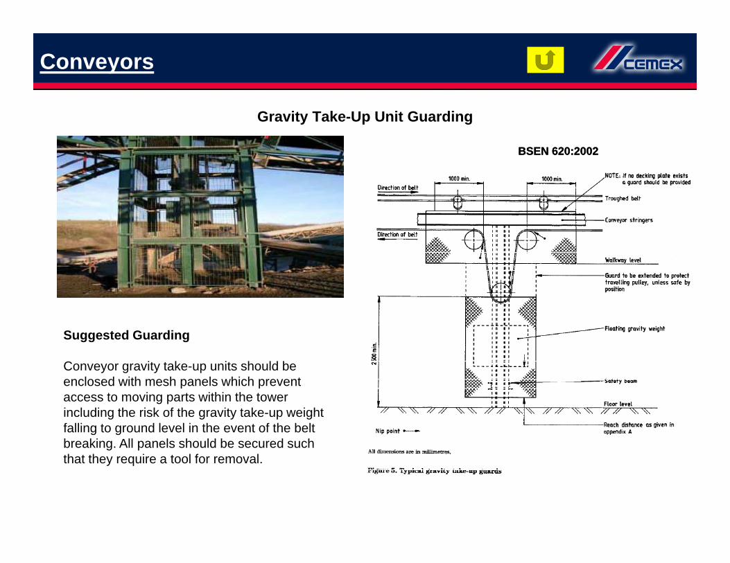
Gravity Take-Up Unit Guarding
BSEN 620:2002BSEN 620:2002
Suggested Guarding
Conveyor gravity take-up units should beenclosed with mesh panels which preventp paccess to moving parts within the towerincluding the risk of the gravity take-up weightfalling to ground level in the event of the beltbreaking. All panels should be secured suchthat they require a tool for removalthat they require a tool for removal.

Conveyors
Remote Greasing and Conveyor Adjustment
All guards should be designed such thatlubrication and adjustment can be carried outwithout removing guards wherever possible

Skips
Hot Storage Skip Winch (sitedat ground level)
Suggested Guarding
A mesh panel guard fence should surround themechanism and be securely fixed to thestructure or foundations. An access gate will berequired which should be secured by means ofa suitable electrically interlocked systema suitable electrically interlocked system.

Skips
Skip Loading Point DistanceGuarding
Suggested Guarding
A mesh panel guard fence should surround themechanism and be securely fixed to thestructure or foundations. An access gate will berequired which should be secured by means ofa suitable electrically interlocked system.
D i G d P i J
Crushers & Screens
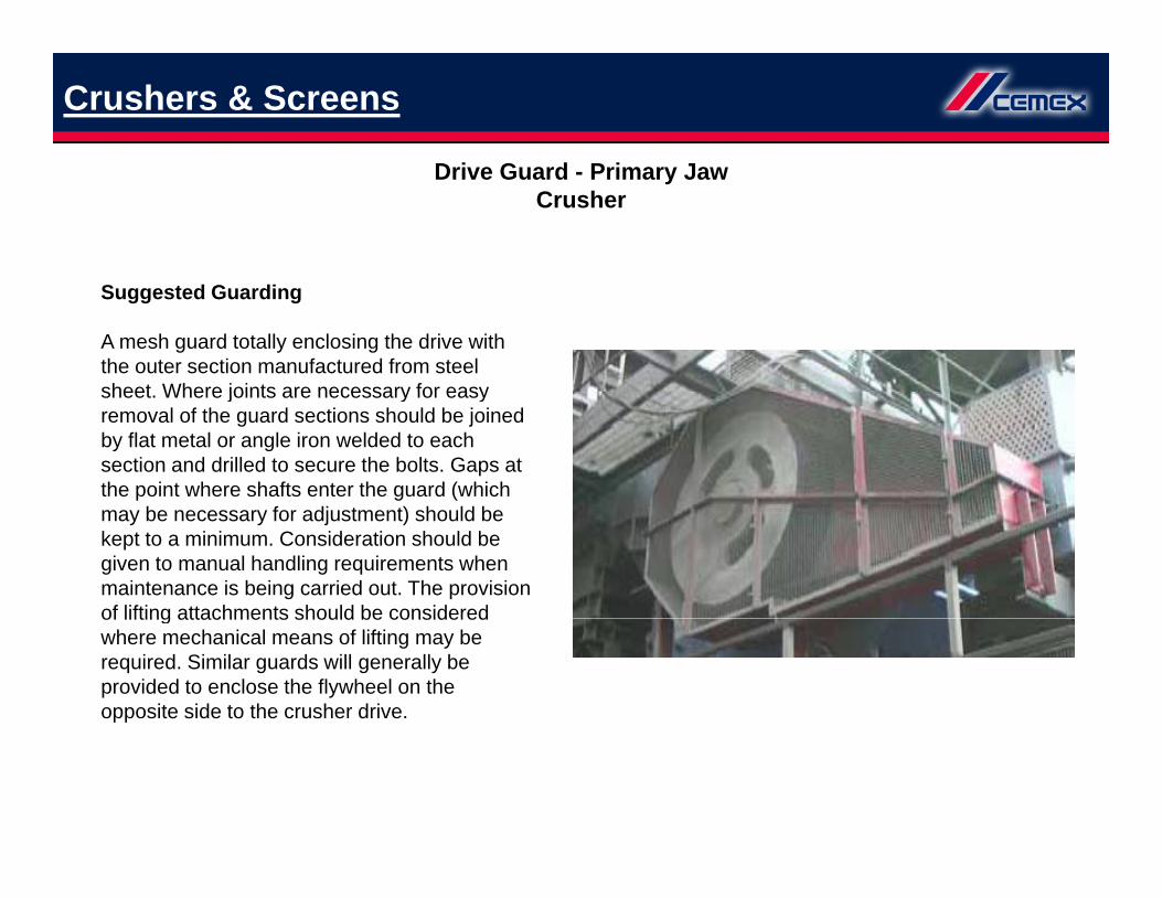
Drive Guard - Primary JawCrusher
Suggested Guarding
A mesh guard totally enclosing the drive withthe outer section manufactured from steelsheet Where joints are necessary for easysheet. Where joints are necessary for easyremoval of the guard sections should be joinedby flat metal or angle iron welded to eachsection and drilled to secure the bolts. Gaps atthe point where shafts enter the guard (whichmay be necessary for adjustment) should bekept to a minimum. Consideration should begiven to manual handling requirements whenmaintenance is being carried out. The provisionof lifting attachments should be consideredof lifting attachments should be consideredwhere mechanical means of lifting may berequired. Similar guards will generally beprovided to enclose the flywheel on theopposite side to the crusher drive.

P i J /T l Pl t
Crushers & Screens
Primary Jaw/Toggle PlateGuarding
Suggested Guarding
A panel of guard is required to prevent accessp g q pto the area immediately behind the crusherswing jaw where movement of the jawpresents a trapping hazard between the jawand the crusher frame.

Crushers & Screens
Guarding over Resonance TypeScreens/Vibrators
Suggested Guardinggg g
Totally enclosing sheet metal guards should beprovided over each of the vibrating units withadditional sheet metal guards over theassociated shafts and couplingsassociated shafts and couplings.
Vib ti S V B lt D i
Crushers & Screens
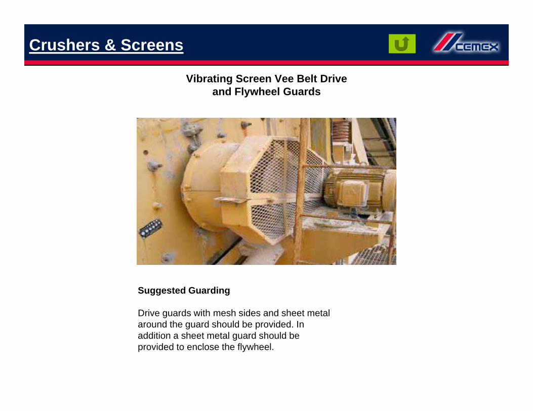
Vibrating Screen Vee Belt Driveand Flywheel Guards
Suggested Guarding
Drive guards with mesh sides and sheet metalaround the guard should be provided. Inaddition a sheet metal guard should beaddition a sheet metal guard should beprovided to enclose the flywheel.

Feed Hoppers
Suggested Guarding
Man Protective Grids in FeedHoppers
Steel grids, to prevent unauthorised orinadvertent entry, should be provided in thetop of all process plant feed hoppers (with theexception of primary dump hoppers or where
d t f l di i b iproducts of a large dimension are beingprocessed which may obstruct the grid). Thegrids should be secured such that they requirea tool for their removal. The aperture size ofthe grid should be designed to enable processg g pmaterial to pass through and be of sufficientstrength to withstand any anticipated loads.
Points for Consideration
• If access hatches are built in the grid thenthey should be secured to require a tool toopen them.
• Fitment of grids on elevated hoppers may
• Storage bins do not normally have protective grids but where they are fed direct by loading shovels grids should be considered. Where such bins cannot be easily accessed and it is not practical to fit grids then there shall be clear signs prohibiting access without a Permit to Work• Fitment of grids on elevated hoppers may
encourage people to walk on them next toan unprotected edge. Appropriate accessprevention measures should be incorporatedin the design
prohibiting access without a Permit to Work.

Ground Feed Hopper
Feed Hoppers
Ground Feed HopperProtective Grids
Steel grids, to prevent unauthorised orinadvertent entry, with sufficient strength towithstand any anticipated loads should be
The grids should be secured such that atool is required for their removal. The aperturesize of the grid should be designed to enable
Suggested Guarding
withstand any anticipated loads, should beprovided in the top of all ground feed hoppers(with the exception of primary dump hoppersor where products of a large dimension arebeing processed which may obstruct the grid).
size of the grid should be designed to enableprocess material to pass through. Provisionshould be made to enable lorry drivers torelease tail gate latches from a positionof safety.

Asphalt Plants
Asphalt Mixer driven by directdrive from two electric motors
Suggested Guarding
A fixed guard is required to enclose the driveg qshafts and flexible couplings connecting theelectric motors to the mixer shafts.
Asphalt Plants
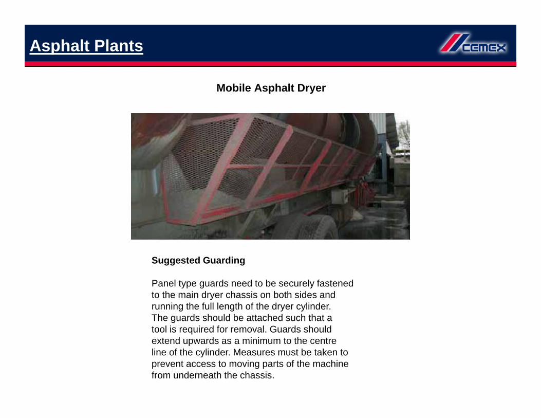
Mobile Asphalt Dryer
Suggested Guarding
Panel type guards need to be securely fastenedyp g yto the main dryer chassis on both sides andrunning the full length of the dryer cylinder.The guards should be attached such that atool is required for removal. Guards shouldextend upwards as a minimum to the centreextend upwards as a minimum to the centreline of the cylinder. Measures must be taken toprevent access to moving parts of the machinefrom underneath the chassis.

P i t G di d
Asphalt Plants
Perimeter Guarding aroundAsphalt plant dryer
Suggested Guarding
Panel type guards are required which shouldbe secured to fixed uprights The minimumbe secured to fixed uprights. The minimumheight of the guard above ground level shouldbe a minimum of two metres. All access gatesshould be secured with a suitable electricallyinterlocked system. Remote greasing lines
fshould be provided to enable lubrication ofbearings to be carried out without entering theguarded area. (See also page 20).
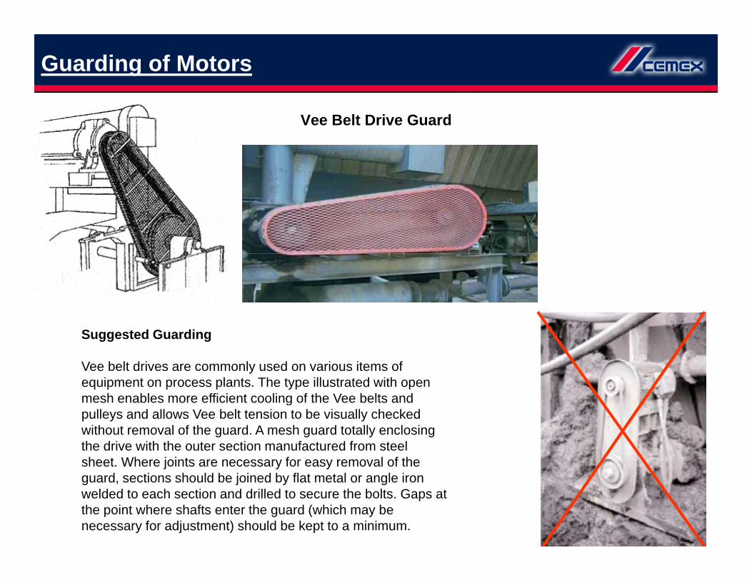
Guarding of Motors
Vee Belt Drive Guard
Suggested Guarding
Vee belt drives are commonly used on various items of equipment on process plants. The type illustrated with open mesh enables more efficient cooling of the Vee belts andmesh enables more efficient cooling of the Vee belts andpulleys and allows Vee belt tension to be visually checked without removal of the guard. A mesh guard totally enclosing the drive with the outer section manufactured from steelsheet. Where joints are necessary for easy removal of the
d i h ld b j i d b fl l l iguard, sections should be joined by flat metal or angle iron welded to each section and drilled to secure the bolts. Gaps at the point where shafts enter the guard (which may be necessary for adjustment) should be kept to a minimum.

M t d R d ti B d i
Guarding of Motors
Motor and Reduction Box driveCoupling
Suggested Guarding
Where using electric motor and wormgreduction gearboxes for driving equipment, thedrive assembly utilises directly coupled shaftswith flexible couplings. Guards are required toenclose the couplings.It is necessary to guard the flexible couplingsIt is necessary to guard the flexible couplingson both the input and output shafts of thegearbox. The guards can be constructed insheet metal or by welding expanded mesh to asteel framework. Where guards obscurelubrication points extension pipes should befitted to avoid removal of the guard whenlubricating the equipment.

Pan Mixers
Pan Mixer Guarding and Interlock
Pan mixer with fibre hatch and interlockSystem
Mixer discharge guarding
Suggested Guarding
The mixer top door should be provided with asuitable electrically interlocked device toprevent the cover being opened unless the
Suggested Guarding
A guard manufactured from sheet metal witha hinged mesh access cover should be
id d t t t i t fprevent the cover being opened unless theelectrical power is disconnected. However fullisolation of the mixer should be undertakenwhen working on the mixer. Inspectionhatches on the mixer cover should be provided
ith d id t t t t ith
provided to prevent access to moving parts ofthe mixer at the discharge point. The hingedmesh top cover should be secured and requirea tool for it to be opened, if frequent access isrequired to this area it should be electrically
with secondary grids to prevent contact withthe moving paddles within, when the mixer isin operation.
q yinterlocked. Where appropriate, lifting eyesshould be attached to the pan mixer lid.

Pan Mixers
Small Pan Mixer
Suggested Guarding
This equipment is normally used inlaboratories.A cover should be provided over the mixerdrum which is electrically interlocked toprevent the mixer operating unless theguard/cover is in position.

Ladders & Gates
Fixed Ladder Gate Systems
Suggested Guarding
Where access to ladders needs to bet ll d hi d l k bl t h ld bcontrolled, a hinged lockable gate should be
provided to prevent unauthorised access. Ifrequired, such gates can be fitted with asuitable electrically interlocked system.NB: Wherever possible, consideration shouldp ,be given to replacing vertical-rung ladders withinclined stairways. New designs shouldincorporate inclined stairways in preference tovertical-rung ladders.

Fixed Ladders
Ladders & Gates
Fixed Ladders
Suggested Guarding
Fixed permanent vertical access ladders to A physical device should be provided to ensurepplatforms, landings and walkways.Ladders rising more than 3.5m should be fittedwith hoops commencing at 2.5m from groundlevel. The hoops should be spaced at 1.2mintervals and connected by three vertical flats
p y pthat there is no risk of personnel falling intothe ladder-way from the top of the ladder.
NB: Wherever possible, consideration shouldbe given to replacing vertical rung laddersintervals and connected by three vertical flats
attached so as to support the weight of thehoops and the user. The internal clearance ofhoops should be in the region of 0.8m.
be given to replacing vertical-rung ladderswith inclined stairways. New designs shouldincorporate inclined stairways in preferenceto vertical-rung ladders
The Workplace, Health, Safety and WelfareRegulations (1992) specify that high rise fixedladders be provided with rest platforms atdistances not exceeding 6m.

Suggested Guarding
Robot Guarding
Suggested Guarding
A fixed perimeter fence should be provided around the working area of the robot. Entry gates into the fenced area should be provided with a suitable electrically interlocked system.Light curtains may beLight curtains may be installed as an additional safeguard to protect personnel if they enter the robot’s immediate working
Entry to Guarded Enclosures around Robots• Before entering the guarded enclosure forteaching purposes, the system must
clear working space of 500mm safety zonemust be provided around the robotoperating envelope. This safety zone must
area.g p p , y
incorporate the facility to request access tothe enclosure via a control which will parkthe robot in a safe position such as home ordatum point. The key exchange system mustdisable the ability to remove the key untilsuch time as the robot arm has returned tothi f i t
p g p ybe clearly marked on the floor andcommunicated to all relevant personnel.• The robot will be fitted with physical stopsto ensure it remains within the necessarysafety zone. The physical stops must alsoprevent the robot extending outside the
d d lthis safe point.• Facility to enable switching from auto modeto ‘teach’ mode must be provided withinthe guarded enclosure using the previouslyreleased key. This will be possible with theguarded enclosure access gate open utilisinga sentry to prevent unauthorised access.
guarded enclosure.• Operation of the ‘teach’ pendant will disablethe operation of the robot from any othercontrol point.• If all of these points cannot be compliedwith, the operation of the ‘teach’ modefrom within the guarded enclosure isa sentry to prevent unauthorised access.
• The robot must operate at no more than10% of its maximum speed in the ‘teach’mode.• If the ‘teach’ mode pendant is to beoperated within the guarded enclosure, a
from within the guarded enclosure isprohibited.• The ‘teach’ mode can only be operated bypersonnel who have received the relevanttraining from either the robot manufactureror someone who is an authorised trainer.

R d Mi d C t
Miscellaneous
Ready-Mixed ConcreteRecycling Plant Discharge Point
Suggested Guarding
A substantial mesh guard is secured at thedischarge point of the aggregates recyclingequipment on a ready-mixed concrete plant.The mesh guard should be provided such toprevent access to the screw mechanism ofthe recycler.

Miscellaneous
Fines Dewaterer
Suggested Guarding
Fines dewaterer using slowly rotating scraperblades to extract the finer particlesblades to extract the finer particles.In addition to a sheet metal guard on themain dewatering section, a mesh guard shouldbe provided around the trough of the scraperblade section. This should be fitted high
h t id l f lli i t thenough to avoid personnel falling into thetrough or being able to reach the scraperblades and be at least 2 metres aboveground level.


![Guarding Equipment 2011 (Canadian) [Read-Only] · Guarding Equipment. Why Do We Need Guarding? The following are common answers or comments ... Head, Drive or Snub Pulleys Before](https://static.fdocuments.in/doc/165x107/5ae470c97f8b9a7b218e6658/guarding-equipment-2011-canadian-read-only-equipment-why-do-we-need-guarding.jpg)