S7 CPs Manual / Part B3 - CP 443-5 Basic · PDF fileManual Part B3 CP 443-5 Basic ......
22
SIMATIC NET S7-CPs for PROFIBUS Manual Part B3 CP 443-5 Basic 6GK7 443-5FX02-0XE0 Version 1 and higher (firmware version V4.0 and higher) for SIMATIC S7-400 / S7-400H PROFIBUS interface (9-pin D-sub female connector) Mode selector Status and fault LEDs
Transcript of S7 CPs Manual / Part B3 - CP 443-5 Basic · PDF fileManual Part B3 CP 443-5 Basic ......

SIMATIC NET
S7-CPs for PROFIBUS
Manual Part B3
CP 443-5 Basic
6GK7 443-5FX02-0XE0 Version 1 and higher (firmware version V4.0 and higher)
for SIMATIC S7-400 / S7-400H
PROFIBUS interface(9-pin D-sub femaleconnector)
Mode selector
Status and fault LEDs

Notes on the Product
B3-2CP 443-5 Basic for PROFIBUS / Manual Part B3
Release 11/2002
C79000-G8976-C161-04
Notes on the Product
Note
All notes in the product information bulletin, which is supplied with this product,are valid and must be observed.
Compatibility with the Previous Version
Note
Make sure that you read the information regarding extended functionality andrestrictions in Chapter 6 of this manual!

B3-3CP 443-5 Basic for PROFIBUS / Manual Part B3Release 11/2002
C79000-G8976-C161-04
Contents
Contents - Part A
PROFIBUS CPs - General Information See General Part. . . . . . . . . . . . . .
Note
Please remember that Part A of the manual also belongs to the description of theCP. Among other things, it contains explanations of the safety notices, references,and general information that applies to all S7 CPs for PROFIBUS.
You can also download this general part from the Internet:
http://www4.ad.siemens.de/view/cs/de/8774037
Contents - Part B3
1 Properties / Services B3-4. . . . . . . . . . . . . . . . . . . . . . . . . . . . . . . . . . . . . . . . . . . . . . . . .
2 Requirements for Use B3-7. . . . . . . . . . . . . . . . . . . . . . . . . . . . . . . . . . . . . . . . . . . . . . . .
2.1 Use with the Current CPU Types B3-7. . . . . . . . . . . . . . . . . . . . . . . . . . . . . . .
2.2 Converting older Systems B3-8. . . . . . . . . . . . . . . . . . . . . . . . . . . . . . . . . . . . .
3 Installation and Commissioning B3-9. . . . . . . . . . . . . . . . . . . . . . . . . . . . . . . . . . . . . .
4 Displays and Mode Selector B3-10. . . . . . . . . . . . . . . . . . . . . . . . . . . . . . . . . . . . . . . . . .
5 Performance Data B3-12. . . . . . . . . . . . . . . . . . . . . . . . . . . . . . . . . . . . . . . . . . . . . . . . . . .
5.1 Supported Transmission Rates B3-12. . . . . . . . . . . . . . . . . . . . . . . . . . . . . . . . .
5.2 Data of S5-Compatible Communication (SEND/RECEIVE Interface) on FDL Connections B3-12. . . . . . . . . . . . . . . . . . . . . . . . . . . . . . . . . . . . . . . . . .
5.3 Data of FMS Connections B3-13. . . . . . . . . . . . . . . . . . . . . . . . . . . . . . . . . . . . .
5.4 Characteristics of S7 Communication B3-14. . . . . . . . . . . . . . . . . . . . . . . . . . .
5.5 Maximum Number of Connections in Total B3-16. . . . . . . . . . . . . . . . . . . . . . .
5.6 Time-of-day Synchronization B3-16. . . . . . . . . . . . . . . . . . . . . . . . . . . . . . . . . . .
5.7 Use in Fault-Tolerant Systems B3-17. . . . . . . . . . . . . . . . . . . . . . . . . . . . . . . . .
5.8 Other Characteristics B3-18. . . . . . . . . . . . . . . . . . . . . . . . . . . . . . . . . . . . . . . . .
6 Compatibility with the Previous Product B3-19. . . . . . . . . . . . . . . . . . . . . . . . . . . . . .
6.1 Extended Functionality Compared with Previous Product B3-19. . . . . . . . . .
6.2 Replacing Older Modules / Replacing Defective Modules B3-20. . . . . . . . . .
7 Technical Specifications B3-22. . . . . . . . . . . . . . . . . . . . . . . . . . . . . . . . . . . . . . . . . . . . .

Properties / Services
B3-4CP 443-5 Basic for PROFIBUS / Manual Part B3
Release 11/2002
C79000-G8976-C161-04
Properties / Services
Application
The CP 443-5 Basic communications processor is designed for use in a SIMATICS7-400 (standard) and S7-400H (fault-tolerant system) programmable controller. Itallows the S7-400 / S7-400H to be connected to a PROFIBUS fieldbus system.
Services
The current version of the CP 443-5 Basic supports the following communicationservices in the standard and H systems:
� PROFIBUS FMS (complying with EN 50170, FMS client and server function)
as FMS master for the following types of connection:
- MMAC: Master-master acyclic
- MSAC: Master-slave acyclic
- MSAC_SI: Master-slave acyclic with slave initiative
- MSCY: Master slave cyclic
- BRCT (broadcast): Sending to all FMS stations
� S7 communication and PG/OP communication
- PG functions with upload / download of FM modules, configuration /diagnostics and routing, user programs
Note on routing: Dynamic switchover to alternative paths (for example ifthere is a problem on one of the possible transmission paths) is notsupported.
- Operator control and monitoring functions (HMI)
- Data exchange using communication function blocks on S7 connections(fault-tolerant S7 connections also possible) 1)
1)Blocks for S7 communication (see also STEP 7 online help or
“System Software for S7-300/400 System and Standard Functions” manual):BSEND SFB 12BRCV SFB 13PUT SFB 14GET SFB 15USEND SFB 8URCV SFB 9START SFB 19STOP SFB 20RESUME SFB 21STATUS SFB 22USTATUS SFB 23CONTROL SFC 62
1

Properties / Services
B3-5CP 443-5 Basic for PROFIBUS / Manual Part B3Release 11/2002
C79000-G8976-C161-04
� S5-compatible communication (SEND/RECEIVE Interface) over FDLconnections of the following types:
- specified FDL connections
- free layer 2 connections
- broadcast
- multicast
� Time-of-day synchronization over PROFIBUS
- The CP forwards time-of-day synchronization frames from the LAN to thestation (CPU = time slave) or from the station to the LAN (CPU= timemaster) or this station is synchronized via a different LAN and thetime-of-day synchronization frame must be forwarded over PROFIBUS forthe synchronization of further stations.
- Time-of-day status value, standard/daylight saving time switchover,synchronization status
The services of the CP 443-5 Basic module listed above can be used at the sametime.
Configuration
When configuring, you must use STEP 7 version V5.2 SP1 or higher; for FDLconnections and diagnostic functions, the NCM S7 for PROFIBUS optionalpackage supplied with STEP 7 must be installed.
If the functionality of the predecessor module is adequate for your purposes,configuration and diagnostics are also possible with earlier STEP 7 versions.
It is possible to configure over the MPI or LAN/PROFIBUS.
System modifications are possible during operation (H system).
Note
For more detailed information on configuring PROFIBUS CP with STEP 7 /NCM S7, refer to the manual NCM S7 for PROFIBUS and the online help ofSTEP 7.
Programming - Using Blocks
For some communication services, there are “off-the-peg” blocks (FCs/FBs)available that implement the interface in your STEP 7 user program. You will find adetailed description of these blocks in the NCM S7 for PROFIBUS manuals.

Properties / Services
B3-6CP 443-5 Basic for PROFIBUS / Manual Part B3
Release 11/2002
C79000-G8976-C161-04
Notice
We recommend that you always use the latest block versions for all module types.
You will find information on the latest block version and links to download thecurrent blocks in our Customer Support on the Internet:
http://www4.ad.siemens.de/view/cs/en/8797900
If you are using older block types, this recommendation only applies if you alsohave the latest firmware version.
You will find further information and Internet addresses in the Preface of theGeneral Part of this manual.
Module Replacement without PG
Depending on the setting in the project configuration, the configuration data canalso be stored in the load memory of the CPU. This makes it possible to replacemodules without having to download the configuration data from the PG.
The stored configuration data is protected from power outage by battery backup orby plugging an EPROM card into the CPU.

Requirements for Use
B3-7CP 443-5 Basic for PROFIBUS / Manual Part B3Release 11/2002
C79000-G8976-C161-04
Requirements for Use
The CP 443-5 Basic described here is supported by all the CPU operating systemslisted in the table below.
The chapter also contains the following information:
� The number of CPs that can be operated with one CPU.
� The number of AG-SEND or AG-RECV calls on the SEND/RECEIVE interfacethat can be active at the same time (data exchange on FDL connections overPROFIBUS and corresponding connections over Industrial Ethernet).
2.1 Use with the Current CPU Types
When operating the CP 443-5 Basic with the CPU types listed here in the table,the following functionality is supported without exception:
� Number of operable CPs: 14
� Multicomputing (except for H systems)
Table 2-1 Use with the Current CPU Types
CPU Order number Firmware version
Number of AG-SEND or AG-RECVcalls at same time
CPU 412 6ES7 412-1XF03-0AB0 As of V3.0 24 / 24
CPU 412-2 6ES7 412-2XG00-0AB0 As of V3.0
CPU414-2 128 KB 6ES7 414-2XG03-0AB0 As of V3.0
CPU414-3 384 KB 6ES7 414-3XJ00-0AB0 As of V3.0
CPU 414-4H 6ES7 414-4HJ00-0AB0 As of V3.0
CPU416-2 0.8 MB 6ES7 416-2XK02-0AB0 As of V3.0 64 / 64
CPU416-3 1.6 MB 6ES7 416-3XL00-0AB0 As of V3.0
CPU 417-4 6ES7 417-4XL00-0AB0 As of V3.0
CPU 417-4H 6ES7 417-4HL00-0AB0 As of V2.1
6ES7 417-4HL01-0AB0 As of V3.0
CPU416F-2 1.6 MB 6ES7 416-2FK02-0AB0 As of V3.1 64 / 64
2

Requirements for Use
B3-8CP 443-5 Basic for PROFIBUS / Manual Part B3
Release 11/2002
C79000-G8976-C161-04
2.2 Converting older Systems
The discontinued CPUs listed here in Table 2-2 support the following functionalityin conjunction with the CP 443-5 Basic:
� Number of operable CPs: 8
� Multicomputing
Table 2-2 Use with Discontinued CPU Types
CPU Order number Version
Number of AG-SEND or AG-RECVcalls at same time
CPU 412 6ES7 412-1XF01-0AB0 2 or higher 12 / 12
6ES7 412-1XF02-0AB0 2 or higher
CPU 413 6ES7 413-1XG01-0AB0 2 or higher
6ES7 413-1XG02-0AB0 1 or higher
CPU 413-2 6ES7 413-2XG01-0AB0 2 or higher
6ES7 413-2XG02-0AB0 1 or higher
CPU414-1 6ES7 414-1XG01-0AB0 2 or higher
6ES7 414-1XG02-0AB0 2 or higher
CPU414-2 128 KB 6ES7 414-2XG01-0AB0 2 or higher
6ES7 414-2XG02-0AB0 2 or higher
CPU414-2 384 KB 6ES7 414-2XJ00-0AB0 4 or higher
6ES7 414-2XJ01-0AB0 2 or higher
CPU416-1 6ES7 416-1XJ01-0AB0 2 or higher 32 / 32
6ES7 416-1XJ02-0AB0 1 or higher
CPU416-2 0.8 MB 6ES7 416-2XK00-0AB0 4 or higher
6ES7 416-1XK01-0AB0 1 or higher
CPU416-2 1.6 MB 6ES7 416-2XL00-0AB0 4 or higher
6ES7 416-2XL01-0AB0 1 or higher

Installation and Commissioning
B3-9CP 443-5 Basic for PROFIBUS / Manual Part B3Release 11/2002
C79000-G8976-C161-04
Installation and Commissioning
Procedure / Steps
Table 3-1
Step Explanation / Meaning
1. Insert the CP 443-5Basic
The CP 443-5 Basic can be inserted in all racks with slots for P and K busattachment:
� Central rack CR2
� Universal rack UR1, UR2 or UR2Has central rackas expansion rack with rack no. 1-6
Note
When using the universal rack as an extension rack, you require an IM with a communication bus link!
The CP 443-5 Basic cannot be operated in an ER1 or ER2 expansion rack(no K bus link possible).
Suitable slots in the rack: With the exception of the slots reserved for the power supply and IM-R, theCP 443-5 Basic can be inserted in all slots with a P and K bus interface (inthe central or in an expansion rack no. 1-6).
2. Attachment toPROFIBUS
Note the information in the General section of this manual.
Note
When using the CR2 rack, the CPU and CP must be plugged into the same segment if you want to useFDL/FMS connections.
3. Configuration Depending on the communication services being used, configuration involvesthe following steps:
� Node initializationThis is necessary in all situations. This assigns a PROFIBUS addressand bus parameters to the PROFIBUS CP. For details, refer to /4/
� Configuring connections:This is necessary when using the communication services, S7 functionsand FDL connections (SEND/RECEIVE interface). For details, refer to /5/or /4/.
4. PG/PC Attachmentfor Configuration
You can connect the PG when configuring the CP as follows:
� via MPI
� via LAN / PROFIBUSThe CP 443-5 Basic must already have a PROFIBUS address (for detailsof node initialization, refer to /4/).
3

Displays and Mode Selector
B3-10CP 443-5 Basic for PROFIBUS / Manual Part B3
Release 11/2002
C79000-G8976-C161-04
Displays and Mode Selector
LEDs Displaying the Status of the CP
The 5 LED indicators on the front panel provide information on the status of the CPas shown in the table below:
Table 4-1
INTF(red)
EXTF(red)
BUSF(red)
RUN(green)
STOP(yellow)
CP-Betriebszustand
Starting up (STOP->RUN)
Running (RUN)
Stopping (RUN->STOP)
Stopped (STOP)
STOP due to internal error (for exampleCP not configured)
� Loading active in RUN.
� RUN with internal error (e.g. badconfigurattion data)
Waiting for firmware update (duration 10seconds after power on)
Waiting for firmware update (CPcurrently has an incomplete firmwareversion).
RUN and PROFIBUS bus errors
Module fault / system error
Key on off flashing
4

Displays and Mode Selector
B3-11CP 443-5 Basic for PROFIBUS / Manual Part B3Release 11/2002
C79000-G8976-C161-04
Controlling the Operating Status
There are different ways of controlling the mode of the CP 443-5 Basic, as follows:
� Mode Selector
� NCM S7 for PROFIBUS configuration software
� SIMATIC Manager in STEP 7
To control the mode from STEP 7 / NCM S7 for PROFIBUS, the mode selectormust be set to RUN.
Mode Selector
With the mode selector, you can set the following operating statuses:
� Switch from STOP to RUN:
The CP reads the configuration data into the work memory and then changes tothe RUN mode.
� Switch from RUN to STOP:
The CP changes to STOP with the following results:
- Established connections (FDL, FMS connections, configured, andunconfigured S7 connections) are terminated
In the STOP mode
- Configuration and diagnostics are possible
- The time of day is distributed

Performance Data
B3-12CP 443-5 Basic for PROFIBUS / Manual Part B3
Release 11/2002
C79000-G8976-C161-04
Performance Data
5.1 Supported Transmission Rates
The transmission rate is set with the SIMATIC STEP 7 configuration software. Forthe permitted rates, refer to Table 7-1 in Chapter 7
5.2 Characteristics of S5-compatible Communication(SEND/RECEIVE Interface) on FDL Connections
The following characteristics are important when operating FDL connections(specified, free layer 2 (SDA and SDN), broadcast, multicast):
Table 5-1
Characteristic Explanation / Values
Total number of FDL connections that can beoperated.
32 maximum
Size of the transferable data area on FDLconnections
240 bytes maximum per specified FDL connection(for sending and receiving)
Free layer 2, broadcast and multicast:
Per job up to 236 bytes of user data can betransferred. The job header requires an additional 4bytes.
Cycle Load Caused by FDL Connections
The cycle load time for FDL connections is largely dependent on the time requiredto execute the function blocks (AG-SEND, AG-RECV) on the S7-400 CPU.
The following table lists the cycle load times of the available FCs in milliseconds. Adistinction is made between the statuses “job completed” and ”job active”. Theentries relate to the run time in the CPU 417-4 (see Table 5-2).
5

Performance Data
B3-13CP 443-5 Basic for PROFIBUS / Manual Part B3Release 11/2002
C79000-G8976-C161-04
Table 5-2
Status Job Completed Job Active
Component / FC min. max. min. max.
AG-SEND 0.12 ms 0.27 ms 0.11 ms 0.29 ms
AG-RECV 0.15 ms 0.37 ms 0.10 ms 0.26 ms
5.3 Data of FMS Connections
The following information is important for operating FMS connections:
Table 5-3
Component Explanation / Values
Maximum number of operable FMS connections 48
User data length 237 bytes for READ233 bytes for WRITE and REPORT
Configurable variables 512 server variables and 2640 variabledescriptions that can be loaded from the partner(maximum values). These can be distributed asrequired on the maximum number of configurableFMS connections. The value applies to elementarydata types or arrays of elementary data types.
This value does not apply to complex data types(STRUCT)! Note the information in the manual /2/about using complex data types (STRUCT).

Performance Data
B3-14CP 443-5 Basic for PROFIBUS / Manual Part B3
Release 11/2002
C79000-G8976-C161-04
Cycle Load Caused by FMS Connections
When calculating the reaction times with FMS connections, the run time of thefunction blocks (FBs) in the S7-400 CPU (416-1 see Table 5-4) is the decisivefactor.
The table below shows the cycle load resulting from the available FCs in ms. Adistinction is made between the statuses “job completed” and ”job active”.
Table 5-4
Status Job Completed Job Active
Component / FB min max min max
READ 1.2 ms 1.6 ms 1.0 ms 2.3 ms
WRITE 1.2 ms 1.6 ms 1.0 ms 2.7 ms
STATUS 1.0 ms 1.5 ms 1.0 ms 2.8 ms
REPORT 1.7 ms 3.1 ms 1.3 ms 4.8 ms
IDENTIFY 1.7 ms 3.1 ms 1.3 ms 4.8 ms
Note
To allow module replacement without a PG, settings on the CPU must bemodified. Open the Properties dialog of the CPU in HW Config; in the “Monitoringtime for” box in the “Startup” tab, check and, if necessary, modify the followingvalues:
- “Transfer of parameters to modules” (recommended value = 600 *100 ms)
Depending on your system (station configuration), you may need to increase thefollowing parameter:
- “Ready message from modules”
For more detailed information about supported services and parameters, refer tothe PICS tables (PICS: Protocol Implementation Conformance Statements) in themanual /4/.
5.4 Characteristics of S7 Communication
The following data is important for operating S7 connections:

Performance Data
B3-15CP 443-5 Basic for PROFIBUS / Manual Part B3Release 11/2002
C79000-G8976-C161-04
Table 5-5
Characteristic Explanation / Values
Number of S7 connections that canbe operated via PROFIBUS
Maximum 48
(The value depends on the S7-400 CPU being used.)

Performance Data
B3-16CP 443-5 Basic for PROFIBUS / Manual Part B3
Release 11/2002
C79000-G8976-C161-04
5.5 Maximum Number of Connections in Total
In total (FDL , FMS , and S7 connections) a maximum of 59 connections can beoperated
As an example, the following multiprotocol configuration was tested:
28 FMS client connections to S7-400/300 with SCC=RCC=1+ 1 FMS server connection to S7-400 with SCC=RCC=4+ 1 FMS server connection to S7-300 with SCC=RCC=1+ 16 FDL connections to S7-400/300+ 8 configured S7 connections to S7-400/300+ 4 unconfigured HMI connections+ Time-of-day forwarding + Diagnostics
Note
If PG or HMI functions are used, a suitable number of S7 connections must bereserved during configuration!
5.6 Time-of-day Synchronization
The CP 443-5 forwards time-of-day synchronization frames in the followingdirections: 1. From the CPU via the CP to PROFIBUS if the local CPU is the time master or
this station is synchronized via a different LAN and the time-of-daysynchronization frame is forwarded via PROFIBUS for the synchronization offurther stations.
2. From PROFIBUS over the CP to the CPU if a remote station is time master, forexample:
- a remote CPU 41x with PROFIBUS interface (for example, CP 443-5)
- a remote PC with CP 5412 / 5613 / 5614
All stations on a PROFIBUS subnet are synchronized with an accuracy of 10 ms.
Note
With transmission rates of < 1.5 Mbps, we recommend that you configure asynchronization interval of at least 10 s.

Performance Data
B3-17CP 443-5 Basic for PROFIBUS / Manual Part B3Release 11/2002
C79000-G8976-C161-04
5.7 Use in Fault-tolerant Systems
With the CP 443-5 Basic, you can operate fault-tolerant S7 connections in an Hsystem.
You will find more detailed information about the possible operating and structuraloptions in the “SIMATIC S7-400H Programmable Controller Manual, Fault-tolerantSystems”.
If the CP 443-5 Basic is used in a fault-tolerant S7-400H system, the followingcommunications services can also be used on single (non-redundant) connections:
� S7 connection for PG functions and PG routing
� S5-compatible communication (SEND/RECEIVE interface) on FDL connections
� FMS connections
� Time-of-day distribution
Note
Please note the CPU types in Table 4-3

Performance Data
B3-18CP 443-5 Basic for PROFIBUS / Manual Part B3
Release 11/2002
C79000-G8976-C161-04
5.8 Other Characteristics
Memory Reset of the CP
!Warning
Please note that when you reset the CP memory using NCM Diagnostics or theSIMATIC Manager, the configuration data on the CPU must also be deletedotherwise the data will become inconsistent.
When using the S7-400H, do not use the memory reset function on the CP!
FMS Operation - Disabling and Enabling Interrupts and Asynchronous Events
Communication using the FMS blocks in the user program can break down ifinterrupts take too long to service (interrupt-driven programs such as hardware anddiagnostic interrupts). You should check the codes in the CP diagnostic buffer.
It is advisable to disable interrupts before calling the FMS blocks and to enablethem again after the FMS block call.
Note
Please read the additional information and notes. These are available in ourCustomer Support on the Internet:
http://www4.ad.siemens.de/view/cs/de/4557726
FMS Mode- Triggering a CP STOP from the PG
If you trigger a CP STOP using a PG function on a CP when using large numbersof connections, it is possible that you may have to repeat the job.
FMS Mode - Startup Behavior of the CPU after POWER ON
In the Properties dialog of the CPU, set “Startup after POWER UP” only to “Warmrestart” or “Cold restart”.

Compatibility with the Previous Product
B3-19CP 443-5 Basic for PROFIBUS / Manual Part B3Release 11/2002
C79000-G8976-C161-04
Compatibility with the Previous Product
6.1 Extended Functionality Compared with PreviousProduct:
The CP 443-5 Basic (6GK7 443-5FX02-0XE0) described here can be used as areplacement for the previous products CP 443-5 Basic (6GK7 443-5FX01-0XE0and 6GK7 443-5FX00-0XE0).
Please note the following information on the extended functionality.
Extended Functions as of 6GK7 443-5FX02 -0XE0
The CP 443-5 Basic (6GK7 443-5FX02-0XE0) is functionally identical to thepredecessor CP 443-5 Basic (6GK7 443-5FX01-0XE0).
The new CP 443-5 Basic provides better performance compared with thepredecessor by a factor of up to 3
Extended Functions as of 6GK7 443-5FX01-0XE0
� PG bus functions in multiple subnets
If you want to use the PG bus functions in multiple subnets, you must install theSTEP 7 software version V5.0 or higher on the PG/PC.
Note: Dynamic switchover to alternative paths (for example if there is a problemon one of the possible transmission paths) is, however, not supported.
� Time-of-day synchronization
� Use in SIMATIC S7-400H (fault-tolerant PLC)
6

Compatibility with the Previous Product
B3-20CP 443-5 Basic for PROFIBUS / Manual Part B3
Release 11/2002
C79000-G8976-C161-04
6.2 Replacing Older Modules / Replacing Defective Modules
Replacing Modules
Please follow the procedure outlined below when replacing an older module withone of those described here:
Table 6-1
Module used until now Configuration Procedure
6GK7 443-5FX00-0XE0 Configuration unchanged (replacing a defective module)
If you have no extra requirements for the CP compared with the oldone, no changes to the configuration are necessary.
You then only need to remember the following difference when usingthe CP:
� Download the configuration data from your PG/PC to the CPagain.
Note the following when forwarding the time of day:
When you have replaced a CP as described, the new CP assumesthe following fixed direction for forwarding the time of day: From LAN to S7 station (can be modified by configuration of the newmodule type, see below)
Extending the Configuration (using new functions)
If you want to use the extended functions of the new CP, follow thesteps outlined below (see also Chapter 3):
1. In STEP 7 / HW Config, replace the already configured CP 443-5Basic with the new module; you will find this in the HardwareCatalog.
2. Modify your configuration according to your requirements, forexample in the Properties dialog for the PROFIBUS subnet.
3. Save, compile, and download the configuration data to the CPUor the CP.
6GK7 443-5FX01-0XE0 Configuration unchanged (replacing a defective module)
If you do not require any extra performance compared with the pre-viously used CP, you do not need to make any changes in the confi-guration
� Download the configuration data from the PG/PC again if the datais stored on the CP and not on the CPU.

Compatibility with the Previous Product
B3-21CP 443-5 Basic for PROFIBUS / Manual Part B3Release 11/2002
C79000-G8976-C161-04
Information in the NCM S7 for PROFIBUS Online Help and Documentation
The information “for new modules” contained in both the STEP 7 / NCM S7 onlinehelp and the NCM S7 for PROFIBUS manual is also relevant for the CP describedhere. Look out for this symbol.
Technical Specifications
B3-22CP 443-5 Basic for PROFIBUS / Manual Part B3
Release 11/2002
C79000-G8976-C161-04
Technical Specifications
General Technical Data
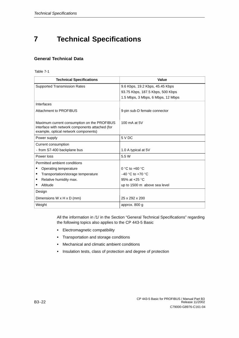
Table 7-1
Technical Specifications Value
Supported Transmission Rates 9.6 Kbps, 19.2 Kbps, 45.45 Kbps
93.75 Kbps, 187.5 Kbps, 500 Kbps
1.5 Mbps, 3 Mbps, 6 Mbps, 12 Mbps
Interfaces
Attachment to PROFIBUS 9-pin sub-D female connector
Maximum current consumption on the PROFIBUSinterface with network components attached (forexample, optical network components)
100 mA at 5V
Power supply 5 V DC
Current consumption
- from S7-400 backplane bus 1.0 A typical at 5V
Power loss 5.5 W
Permitted ambient conditions
� Operating temperature
� Transportation/storage temperature
� Relative humidity max.
� Altitude
0 °C to +60 °C-40 °C to +70 °C95% at +25 °Cup to 1500 m above sea level
Design
Dimensions W x H x D (mm) 25 x 292 x 200
Weight approx. 800 g
All the information in /1/ in the Section “General Technical Specifications” regardingthe following topics also applies to the CP 443-5 Basic
� Electromagnetic compatibility
� Transportation and storage conditions
� Mechanical and climatic ambient conditions
� Insulation tests, class of protection and degree of protection
7