Dynamic Harmonic Domain Modeling of Flexible Alternating ...

GPU TECHNOLOGY CONFERENCE:
S6465: Physics-Based Modeling of Flexible Tires on Deformable Terrain with the GPU
Daniel Melanz, Dan Negrut
Simulation-Based Engineering LaboratoryUniversity of Wisconsin - Madison

Overview
1) Motivation & Background
2) The Tire
3) The Terrain
4) Tire-Terrain Interaction
5) Validation
6) Conclusions & Future Work
4/7/2016 2University of Wisconsin

Energid
Motivation
2/2/2016 3

The Tire
4/7/2016 University of Wisconsin 4

ANCF – What is it?
• Absolute Nodal Coordinate Formulation
• Used for the dynamics analysis of flexible bodies that undergo large deformation
• It is consistent with the nonlinear theory of continuum mechanics
• It is computationally efficient:• Constant mass matrix
• Zero Coriolis and centrifugal effects
• Several opportunities for parallelism
4/7/2016 University of Wisconsin 5
ANCF – How is it defined?
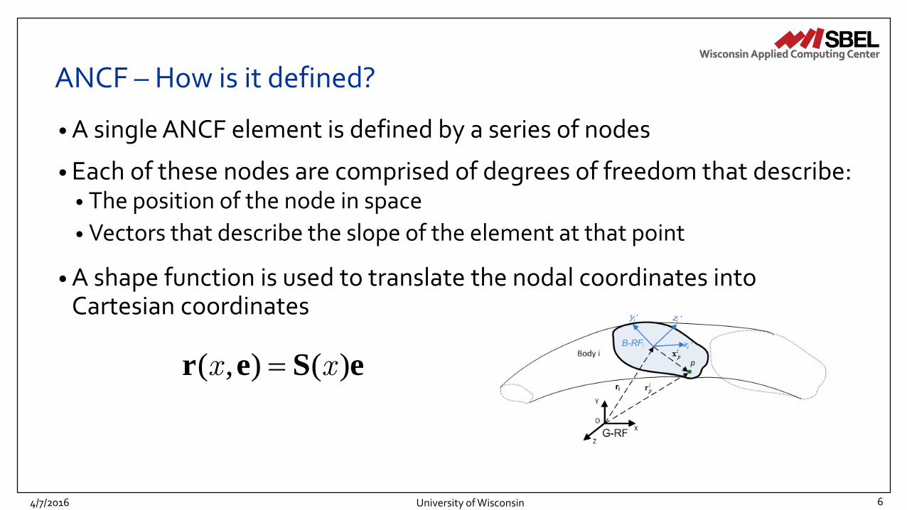
• A single ANCF element is defined by a series of nodes
• Each of these nodes are comprised of degrees of freedom that describe:• The position of the node in space
• Vectors that describe the slope of the element at that point
• A shape function is used to translate the nodal coordinates into Cartesian coordinates
4/7/2016 University of Wisconsin 6
( , ) ( )r e S ex x

ANCF – How does it work?
• Now that we can describe a particular element, we can do useful things with it
• Using the Principle of Virtual Work for the continuum, the following governing differential equation is obtained:
• We can use this to determine how the element moves over time!
4/7/2016 University of Wisconsin 7
s e Me Q Q

ANCF – Mass
• Getting the mass is easy:
• Can be performed as a preprocess
4/7/2016 University of Wisconsin 8
T
o
o
V
dV
M S S

ANCF – External Forces
• Getting the external force is easy:• Due to gravity:
• Due to a concentrated force:
• Can be used to apply contact!
4/7/2016 University of Wisconsin 9
T
e Q S f
0
l
T
e gA dx Q S f
ANCF – Internal Forces
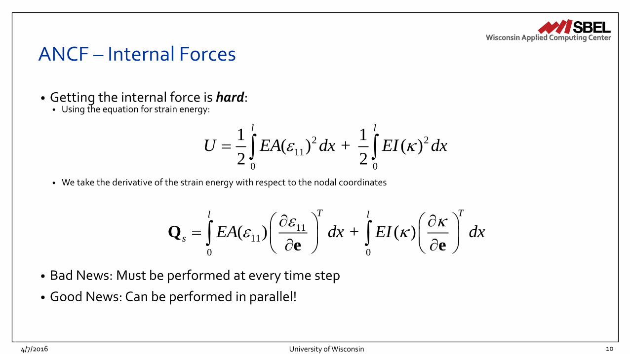
• Getting the internal force is hard:• Using the equation for strain energy:
• We take the derivative of the strain energy with respect to the nodal coordinates
• Bad News: Must be performed at every time step
• Good News: Can be performed in parallel!
4/7/2016 University of Wisconsin 10
2 2
11
0 0
1 1( ) + ( )
2 2
l l
U EA dx EI dx
1111
0 0
( ) + ( )
T Tl l
s EA dx EI dx
Qe e

ANCF Examples
4/7/2016 University of Wisconsin 11

ANCF – GPU Details (Internal Forces)
1
4/7/2016 University of Wisconsin 12
2
3
04
56
A
BSimple mesh:
- 2 elements (A&B)
- 7 nodes (0-6)
Element A: Nodes 0-1-2-3
Element B: Nodes 3-4-5-6
0
0
1
1
2 3
32
4
43
5
5
6
6
Memory representation: Nodal information
Memory representation: Internal force information
Problem: Node overlap results in race conditions!
Solution: Internal forces are calculated on a per element basis, a parallel reduce-by-key is used transform the element data into nodal data

Modeling the Tire
4/7/2016 University of Wisconsin 13

Modeling the Tire
4/7/2016 University of Wisconsin 14

The Terrain
4/7/2016 University of Wisconsin 15

Terrain Models (Terramechanics)
2/2/2016 Energid 16
• There are three main techniques that are used to study terramechanics:

Empirical Methods
2/2/2016 Energid 17
• A force balance in the vertical direction yields an equation for the weight, W, of the tire:
• Once the limits of the contact patch are determined, the drawbar pull and torque can be calculated by integrating the stresses over the wheel
W = rbq2
q1
ò s cosq +t sinq( )dq
Forces, torques, and stresses on a driven, rigid wheel. Dynamic Bekker implementation.

Continuum Methods
2/2/2016 Energid 18
• Continuum methods assume matter to be homogeneous and continuous
• Uses a set of partial differential equations (PDE) with boundary conditions
• Meshes are adopted to approximate the solution
• Examples: FDM, FVM, FEM
Continuum model (behind). Continuum model (above).
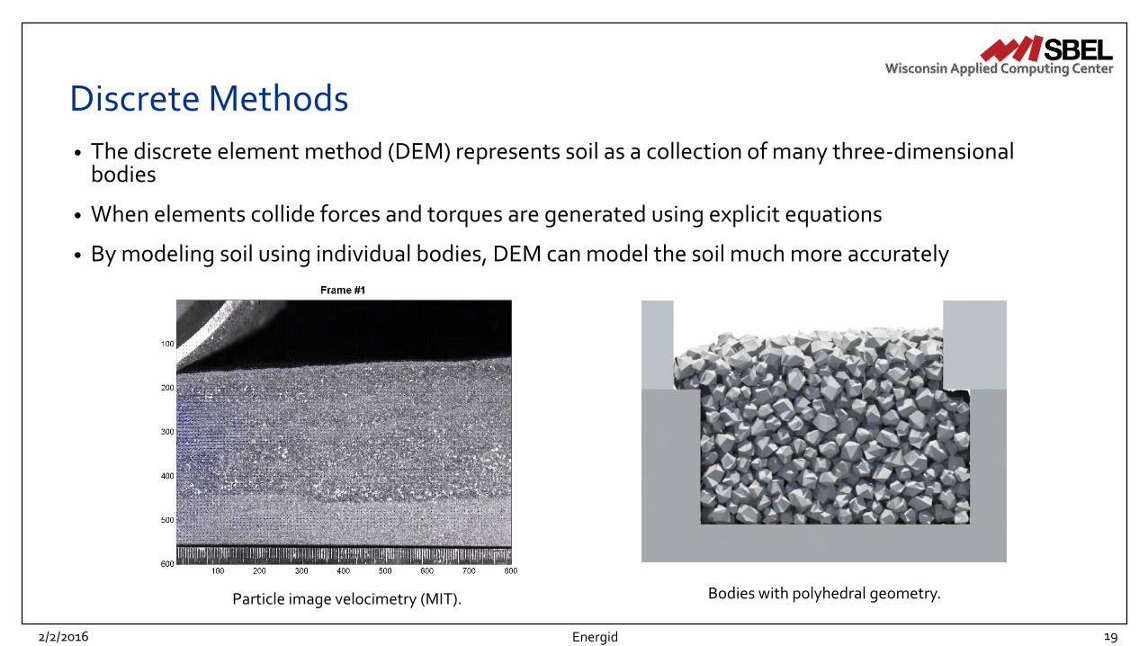
Discrete Methods
2/2/2016 Energid 19
• The discrete element method (DEM) represents soil as a collection of many three-dimensional bodies
• When elements collide forces and torques are generated using explicit equations
• By modeling soil using individual bodies, DEM can model the soil much more accurately
Bodies with polyhedral geometry.Particle image velocimetry (MIT).
Tire-Terrain Interaction
4/7/2016 University of Wisconsin 20

Energid
The Complementarity Approach
2/2/2016
• Two important concepts
1) Accounting for contact through complementarity
2) Posing Coulomb’s friction as an optimization problem
21
Energid
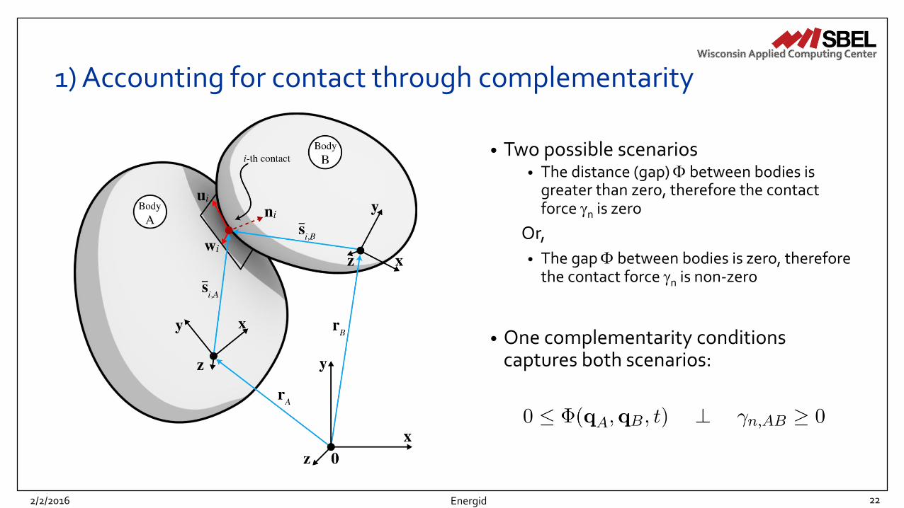
1) Accounting for contact through complementarity
2/2/2016
• Two possible scenarios• The distance (gap) between bodies is
greater than zero, therefore the contact force n is zero
Or,
• The gap between bodies is zero, therefore the contact force n is non-zero
• One complementarity conditions captures both scenarios:
22
Energid
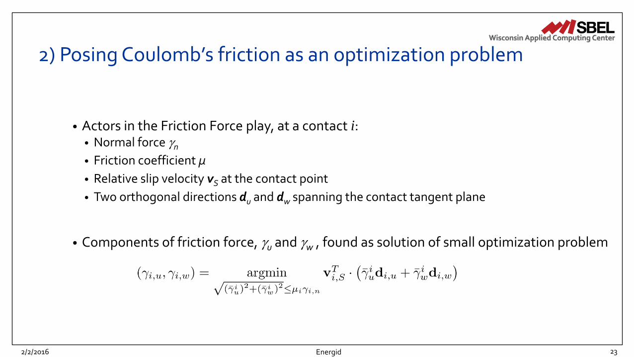
2) Posing Coulomb’s friction as an optimization problem
2/2/2016
• Actors in the Friction Force play, at a contact i:• Normal force n• Friction coefficient µ
• Relative slip velocity vS at the contact point
• Two orthogonal directions du and dw spanning the contact tangent plane
• Components of friction force, u and w , found as solution of small optimization problem
23

4/7/2016 24
Complementarity Approach: The Math

4/7/2016 25
Complementarity Approach: The Math

4/7/2016 26
D.E. Stewart and J.C. Trinkle. An implicit time-stepping scheme for rigid body dynamics with inelastic collisions and coulomb friction. IJNME, 39:2673-2691, 1996.
Complementarity Approach: The Math

4/7/2016 27
M. Anitescu, Optimization-based Simulation of Nonsmooth Rigid Multibody Dynamics, Math. Program. 105 (1)(2006) 113-143
Complementarity Approach: The Math
4/7/2016 28
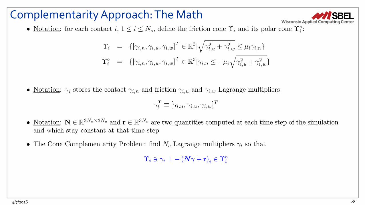
Complementarity Approach: The Math

Energid
The Optimization Angle
2/2/2016 29

4/7/2016 30
Time Integration• Life is good once the frictional contact forces at the interface
between shapes are available
• Velocity at new time step l+1 computed as
• Once velocity available, the new set of generalized coordinates computed as

Energid
Complementarity Approach: Putting Things in Perspective
2/2/2016
• Complementarity conditions employed to link distance between shapes and normal force
• Friction posed as an optimization problem
• Equations of motion became equilibrium constraints, an appendix to optimization problem
• DVI discretized to lead to nonlinear complementarity problem
• Relaxation yields CCP, which was solved via a QP with conic constraints to compute
31

4/7/2016 University of Wisconsin 32
Tire-Terrain Interaction

Tire-Terrain Interaction
4/7/2016 University of Wisconsin 33

University of Wisconsin -Madison
DEM – GPU Details (Collision Detection)
6/29/2015 34
• Generate pair-wise geometrical information
• Efficient implementations• Broad phase
• Narrow phase
• Example: 2D collision detection, bins are squares• Body 4 touches bins A4, A5, B4, B5
• Body 7 touches bins A3, A4, A5, B3, B4, B5, C3, C4, C5
• In proposed algorithm, bodies 4 and 7 will be checked for collision by three threads (associated with bin A4, A5, B4)

Validation
4/7/2016 University of Wisconsin 35

Longitudinal Slip Test - Setup
4/7/2016 University of Wisconsin 36
Source: http://insideracingtechnology.com/

Longitudinal Slip Test - Results
4/7/2016 University of Wisconsin 37
Source: http://insideracingtechnology.com/
Slip [-]-1.5 -1 -0.5 0 0.5 1
Dra
wbar
Pull
Coeff
icie
nt [-
]
-0.25
-0.2
-0.15
-0.1
-0.05
0
0.05
0.1
0.15
0.2
0.25

Single Wheel Test - SetupInvestigates the contact stresses, drawbar pull, wheel torque, and sinkage of a wheel under controlled wheel slip and normal loading
Energid2/2/2016 38

• Measurements were taken for drawbar pull, torque, and sinkage
2/2/2016 Energid
Single Wheel Test – Experimental Data
Drawbar Pull vs. Slip Torque vs. Slip Sinkage vs. Slip
39

2/2/2016 Energid
Single Wheel Test – DEM ValidationDrawbar Pull vs. Slip Torque vs. Slip Sinkage vs. Slip
No
rma
l lo
ad
= 8
0 N
No
rma
l lo
ad
= 1
30 N
40

Single Wheel Test - Particle Tracking
Energid2/2/2016 41

Single Wheel Test - Slip Ratio
Energid
Negative Slip (Towed Wheel)
Zero Slip (Perfect Rolling)
Positive Slip (Driven Wheel)
2/2/2016 42

Conclusions & Future Work
4/7/2016 University of Wisconsin 43

Conclusions
• Our goal is to enable Chrono to solve complex, engineering problemsthrough the use of novel algorithms implemented on state-of-the-art hardware
• The discrete element method of terramechanics using contact through complementarity has been validated against both analytical and experimental results
• Flexible bodies(Absolute Nodal Coordinate Formulation) are combined with deformable terrain to model complex off-road vehicle dynamics
4/7/2016 44University of Wisconsin

Future Work
• Use a more robust ANCF plate element for tire modeling
• Perform lateral validation tests
• Incorporate distributed normal force on element face to simulate tire pressure
• Attach the tire to a full vehicle
4/7/2016 45University of Wisconsin

Thank you.
• Source available for download under BSD-3 http://spikegpu.sbel.org/
• For all of our animations, please visit https://vimeo.com/uwsbel
• For more information about the Simulation-Based Engineering Laboratory, please visit http://sbel.wisc.edu/
University of Wisconsin 464/7/2016

Thank You.
Simulation Based Engineering Lab
Wisconsin Applied Computing Center
4/7/2016 47University of Wisconsin