S4KC 208 V, 6000 & 10000 VA Instruction Manual, January … · 3.0 Major Components 12 3.1 main...
56
Industrial On-Line UPS - 208 V, 6000 & 10000 VA S4KC Series Instruction Manual
Transcript of S4KC 208 V, 6000 & 10000 VA Instruction Manual, January … · 3.0 Major Components 12 3.1 main...

Industrial On-Line UPS - 208 V, 6000 & 10000 VA
S4KC Series
Instruction Manual

While every precaution has been taken to ensure accuracy and completeness in this manual, Appleton Grp LLC d/b/a Appleton Group assumes no responsibility, and disclaims all liability for damages resulting from use of this information or for any errors or omissions.
The SolaHD and Emerson logos are registered in the U.S. Patent and Trademark Office. All other product or service names are the property of their registered owners.
©2018 Appleton Grp LLC d/b/a Appleton Group. All rights reserved. Specifications are subject to change without notice.

S4KC SEriES USEr mAnUAL | iii
Contents
Important Safety Precautions 6Save these instructions . . . . . . . . . . . . . . . . . . . . . . . . . . . . . . . . . . . . . . . . . . . . . . . 6
Glossary of Symbols . . . . . . . . . . . . . . . . . . . . . . . . . . . . . . . . . . . . . . . . . . . . . . . . . 8
1.0 Introduction 9
2.0 System Description 102.1 Surge Protection Devices (SPD) & Emi/rFi Filters . . . . . . . . . . . . . . . . . . . . . . . . . . . . . . . . . 10
2.2 rectifier/Power Factor Correction (PFC) Circuit . . . . . . . . . . . . . . . . . . . . . . . . . . . . . . . . . . 10
2.3 inverter . . . . . . . . . . . . . . . . . . . . . . . . . . . . . . . . . . . . . . . . . . . . . . . . . . . . . 10
2.4 Battery Charger . . . . . . . . . . . . . . . . . . . . . . . . . . . . . . . . . . . . . . . . . . . . . . . . . 11
2.5 Dc-to-Dc Converter . . . . . . . . . . . . . . . . . . . . . . . . . . . . . . . . . . . . . . . . . . . . . . . 11
2.6 Battery . . . . . . . . . . . . . . . . . . . . . . . . . . . . . . . . . . . . . . . . . . . . . . . . . . . . . 11
2.7 Dynamic Bypass . . . . . . . . . . . . . . . . . . . . . . . . . . . . . . . . . . . . . . . . . . . . . . . . . 11
3.0 Major Components 123.1 main Frame & Electronics . . . . . . . . . . . . . . . . . . . . . . . . . . . . . . . . . . . . . . . . . . . . 12
3.2 removable Power Distribution Box . . . . . . . . . . . . . . . . . . . . . . . . . . . . . . . . . . . . . . . . 14
3.3 internal Battery Packs . . . . . . . . . . . . . . . . . . . . . . . . . . . . . . . . . . . . . . . . . . . . . . 16
4.0 Preinstallation 174.1 Unpacking & inspection . . . . . . . . . . . . . . . . . . . . . . . . . . . . . . . . . . . . . . . . . . . . . 17
4.2 What’s included . . . . . . . . . . . . . . . . . . . . . . . . . . . . . . . . . . . . . . . . . . . . . . . . . 17
5.0 Installation 185.1 installation Environment . . . . . . . . . . . . . . . . . . . . . . . . . . . . . . . . . . . . . . . . . . . . . 18
5.2 installing the main Cabinet. . . . . . . . . . . . . . . . . . . . . . . . . . . . . . . . . . . . . . . . . . . . 18
5.3 External Battery Cabinet installation . . . . . . . . . . . . . . . . . . . . . . . . . . . . . . . . . . . . . . . 23
5.4 Connect input/Output Power . . . . . . . . . . . . . . . . . . . . . . . . . . . . . . . . . . . . . . . . . . 25

iv | Contents
6.0 Configuration Program 296.1 Configuration Program Features . . . . . . . . . . . . . . . . . . . . . . . . . . . . . . . . . . . . . . . . . 29
7.0 Controls & Indicators 307.1 On/Alarm Silence/manual Battery Test Button . . . . . . . . . . . . . . . . . . . . . . . . . . . . . . . . . . 30
7.2 Standby/manual Bypass Button . . . . . . . . . . . . . . . . . . . . . . . . . . . . . . . . . . . . . . . . . 31
7.3 Load Level indicators . . . . . . . . . . . . . . . . . . . . . . . . . . . . . . . . . . . . . . . . . . . . . . 31
7.4 Battery Level indicators . . . . . . . . . . . . . . . . . . . . . . . . . . . . . . . . . . . . . . . . . . . . . 32
7.5 UPS Status indicators . . . . . . . . . . . . . . . . . . . . . . . . . . . . . . . . . . . . . . . . . . . . . . 33
8.0 Operation 348.1 Startup Checklist for the S4KC . . . . . . . . . . . . . . . . . . . . . . . . . . . . . . . . . . . . . . . . . . 34
8.2 initial Startup & Electrical Checks . . . . . . . . . . . . . . . . . . . . . . . . . . . . . . . . . . . . . . . . . 34
8.3 manual Battery Test . . . . . . . . . . . . . . . . . . . . . . . . . . . . . . . . . . . . . . . . . . . . . . . 35
8.4 Put the S4KC in manual Bypass . . . . . . . . . . . . . . . . . . . . . . . . . . . . . . . . . . . . . . . . . . 35
8.5 Shut Down the S4KC . . . . . . . . . . . . . . . . . . . . . . . . . . . . . . . . . . . . . . . . . . . . . . . 35
8.6 Disconnecting input Power from the S4KC . . . . . . . . . . . . . . . . . . . . . . . . . . . . . . . . . . . . 35
8.7 maintenance Bypass . . . . . . . . . . . . . . . . . . . . . . . . . . . . . . . . . . . . . . . . . . . . . . . 35
9.0 Communication 369.1 Communication interface Port . . . . . . . . . . . . . . . . . . . . . . . . . . . . . . . . . . . . . . . . . . 36
9.2 Terminal Block Communication . . . . . . . . . . . . . . . . . . . . . . . . . . . . . . . . . . . . . . . . . 36
9.3 UPS intelliSlot Communication Cards . . . . . . . . . . . . . . . . . . . . . . . . . . . . . . . . . . . . . . . 38
9.4 remote Emergency Power Off . . . . . . . . . . . . . . . . . . . . . . . . . . . . . . . . . . . . . . . . . . 38
10.0 Maintenance 3910.1 replacing the internal Battery Pack . . . . . . . . . . . . . . . . . . . . . . . . . . . . . . . . . . . . . . . 39
10.2 Battery Charging . . . . . . . . . . . . . . . . . . . . . . . . . . . . . . . . . . . . . . . . . . . . . . . . 41
10.3 Precautions . . . . . . . . . . . . . . . . . . . . . . . . . . . . . . . . . . . . . . . . . . . . . . . . . . 41
10.4 Checking UPS Status . . . . . . . . . . . . . . . . . . . . . . . . . . . . . . . . . . . . . . . . . . . . . . 41
10.5 Checking UPS Functions . . . . . . . . . . . . . . . . . . . . . . . . . . . . . . . . . . . . . . . . . . . . 41
10.6 replacing the Power module on S4K6U10KC . . . . . . . . . . . . . . . . . . . . . . . . . . . . . . . . . . 42

S4KC SEriES USEr mAnUAL | v
11.0 Troubleshooting 4411.1 UPS Symptoms . . . . . . . . . . . . . . . . . . . . . . . . . . . . . . . . . . . . . . . . . . . . . . . . . 44
11.2 Troubleshooting . . . . . . . . . . . . . . . . . . . . . . . . . . . . . . . . . . . . . . . . . . . . . . . . 46
12.0 Specifications 4812.1 Auto-learning Battery Backup Times. . . . . . . . . . . . . . . . . . . . . . . . . . . . . . . . . . . . . . . 54
13.0 Warranty & Support 5513.1 Warranty information. . . . . . . . . . . . . . . . . . . . . . . . . . . . . . . . . . . . . . . . . . . . . . 55
13.2 Technical Support . . . . . . . . . . . . . . . . . . . . . . . . . . . . . . . . . . . . . . . . . . . . . . . 55

6 | important Safety Precautions
imPOrTAnT SAFETy PrECAUTiOnS
SAVE THESE INSTRUCTIONSThis manual contains important safety instructions. read all safety and operating instructions before operating the Uninterruptible Power System (UPS). Adhere to all warnings on the unit and in this manual. Follow all operating and user instructions. This equipment can be operated by individuals without previous training.
This product is designed for commercial/industrial use only. it is not intended for use with life support or other designated “critical” devices. maximum load must not exceed that shown on the UPS rating label. The UPS is designed for data processing equipment. if uncertain, consult your dealer or local SolaHD representative.
This UPS is designed for use on a properly grounded (earthed) 50 or 60 Hz supply. The factory default setting is 120/208 Vac, 60 Hz. installation instructions and warning notices are in this manual.
The S4KC is designed for use with a four-wire input (L1, L2, n, G).
! wARNINgAlthough the S4KC has been designed and manufactured to ensure personal safety, improper use can result in electrical shock or fire. To ensure safety, observe the following precautions:
• Turn off the UPS and disconnect it from the power source before cleaning.
• Clean the UPS with a soft, dry cloth. Do not use liquid or aerosol cleaners.
• Never block or insert any objects into the ventilation holes or other openings of the UPS.
• If using the UPS power cord, place it in a location where it will not be damaged.
Operate the UPS in an indoor environment only, in an ambient temperature range of 0°C to +40°C (+32°F to +104°F).
Temperature Rating (all models): Units are considered acceptable for use in a maximum ambient of +30°C for ambient operation without derating. in addition, output derating (90%) may be applied for use in a maximum ambient between +30°C and +40°C. Please see Table 8 for details of the derating declaration.
install the UPS in a clean environment, free from moisture, flammable liquids, gases, and corrosive substances.
The S4K4U6000C contains no user-serviceable parts. The S4K6U10KC contains no user-serviceable parts, except for the power module. The UPS On/Off buttons do not electrically isolate internal parts. Under no circumstances should you attempt to gain access internally due to the risk of electric shock or burn. The internal battery pack may be replaced by qualified service personnel only.
Do not continue to use the UPS if the front panel indications are not in accordance with these operating instructions or the UPS performance alters in use. refer all faults to your SolaHD representative.
DO nOT COnnECT equipment that could overload the UPS or demand dc current from the UPS, such as: electric drills, vacuum cleaners, laser printers, hair dryers, or any appliance using half-wave rectification.
Storing magnetic media on top of the UPS may result in data loss or corruption.
The UPS handle is not for transit.

S4KC SEriES USEr mAnUAL | 7
Battery Safety Notes! CAUTION
Do not dispose of batteries in a fire; they may explode. Dispose of used batteries according to local regulations.
Do not open or mutilate the batteries. Released electrolyte is toxic and harmful to skin and eyes. If electrolyte comes in contact with the skin, wash the affected area immediately and get medical attention.
! CAUTIONA battery can present a risk of electrical shock and high short-circuit current. Servicing of batteries should be performed or supervised by personnel knowledgeable of batteries and the required precautions.
The following precautions should be observed when working with batteries:
• Remove watches, rings, and other metal objects.
• Use tools with insulated handles.
• Wear rubber gloves, boots, and safety glasses.
• Do not lay tools or metal parts on top of batteries.
• If the battery pack is damaged in any way or shows signs of leakage, please contact your SolaHD representative immediately.
• Disconnect charging source prior to connecting or disconnecting battery terminals.
• Determine if the battery is inadvertently grounded. If it is inadvertently grounded, remove the source from the ground. Contact with any part of a grounded battery can result in electrical shock. The likelihood of such shock can be reduced if grounds are removed during installation and maintenance (applicable to a UPS and a remote battery supply not having a grounded supply circuit).
• When replacing batteries, replace with the same type and number of batteries or battery packs.
Electromagnetic CompatibilityThe S4KC complies with the limits for a CLASS A DiGiTAL DEViCE, PUrSUAnT TO Part 15 of FCC rules. Operation is subject to the following two conditions: (1) This device may not cause harmful interference and (2) This device must accept any interference received, including interference that may cause undesired operation. Operating this device in a residential area is likely to cause harmful interference that users must correct at their own expense.
The S4KC Series complies with the requirements of EmC Directive 2004/108/EC and the published technical standards. Continued compliance requires installation in accordance with these instructions and use of accessories approved by SolaHD.
NOTICE: This product is for restricted sales distribution to informed partners. installation restrictions or additional measures may be needed to prevent radio interference.
Information for the Protection of the EnvironmentUPS Servicing: The UPS makes use of components dangerous for the environment (e.g. batteries, electronic cards, and electronic components). The discarded components must be taken to a specialized collection and disposal center.

8 | important Safety Precautions
glossary of Symbols
Risk of electrical shock
Indicates caution followed by important instructions
AC input
AC output
Requests the user to consult the manual
Indicates the unit contains a valve-regulated lead acid battery
Recycle
DC voltage
Equipment grounding conductor
Bonded to ground
AC voltage
ON/Alarm Silence/Battery Test
OFF/Bypass
WEEE
!
i
PbH2SO4
- +
R

S4KC SEriES USEr mAnUAL | 9
1.0 introductionCongratulations on your choice of the SolaHD S4KC Uninterruptible Power System (UPS). The S4KC is available in nominal power ratings of 6,000 VA and 10,000 VA.
The S4KC is a compact, on-line Uninterruptible Power System (UPS) which continuously conditions and regulates its output voltage, whether utility power is present or not. it is designed to supply microcomputers and other sensitive equipment with clean sine wave power.
The S4KC features a light-emitting diode (LED) display to indicate both load percentage and battery capacity. it also provides self-diagnostic tests, a combination On/Alarm Silence/manual Battery Test button, and a Standby/manual Bypass button.
The S4KC has an intelliSlot® port for communication between the UPS and a network server or other computer system. This port provides detailed operating information including voltages, currents, and alarm status to the host system when used in conjunction with multiLink®. multiLink can also remotely control UPS operation.
10 | 2.0 System Description
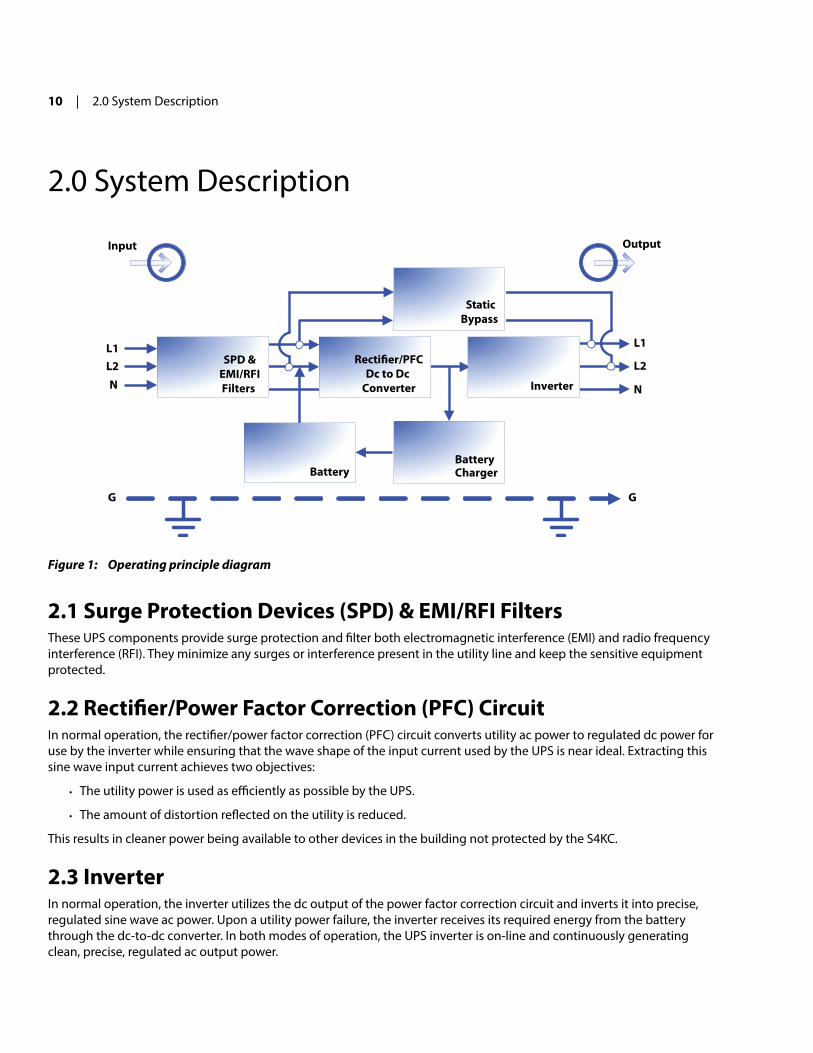
2.0 System Description
Input Output
Inverter
Battery
Recti�er/PFCDc to Dc
Converter
SPD &EMI/RFIFilters
L1
G G
StaticBypass
L2
N
L1L2N
BatteryCharger
Figure 1: Operating principle diagram
2.1 Surge Protection Devices (SPD) & EMI/RFI FiltersThese UPS components provide surge protection and filter both electromagnetic interference (Emi) and radio frequency interference (rFi). They minimize any surges or interference present in the utility line and keep the sensitive equipment protected.
2.2 Rectifier/Power Factor Correction (PFC) Circuitin normal operation, the rectifier/power factor correction (PFC) circuit converts utility ac power to regulated dc power for use by the inverter while ensuring that the wave shape of the input current used by the UPS is near ideal. Extracting this sine wave input current achieves two objectives:
• The utility power is used as efficiently as possible by the UPS.
• The amount of distortion reflected on the utility is reduced.
This results in cleaner power being available to other devices in the building not protected by the S4KC.
2.3 Inverterin normal operation, the inverter utilizes the dc output of the power factor correction circuit and inverts it into precise, regulated sine wave ac power. Upon a utility power failure, the inverter receives its required energy from the battery through the dc-to-dc converter. in both modes of operation, the UPS inverter is on-line and continuously generating clean, precise, regulated ac output power.

S4KC SEriES USEr mAnUAL | 11
2.4 Battery ChargerThe battery charger utilizes energy from the utility power and precisely regulates it to continuously float charge the batteries. The batteries are being charged whenever the S4KC is connected to utility power.
2.5 Dc-to-Dc ConverterThe dc-to-dc converter utilizes energy from the battery system and raises the dc voltage to the optimum operating voltage for the inverter. This allows the inverter to operate continuously at its optimum efficiency and voltage, thus increasing reliability.
2.6 BatteryThe S4KC utilizes valve-regulated, non-spillable, lead acid batteries. To maintain battery design life, operate the UPS in an ambient temperature of -15°C to +25°C (+59°F to +77°F). Optional external battery cabinets are available to extend battery backup times. For backup times, see Table 13.
2.7 Dynamic BypassThe S4KC provides an alternate path for utility power to the connected load in the unlikely event of a UPS malfunction. Should the UPS have an overload, overtemperature, or any other UPS failure condition, the UPS automatically transfers the connected load to bypass. Bypass operation is indicated by an audible alarm and an illuminated amber Bypass LED. (Other LEDs may be illuminated to indicate a diagnosed problem.) To manually transfer the connected load from the inverter to bypass, press the Standby/manual Bypass button once and hold it for about 2 seconds.
NOTE: The bypass power path does nOT protect the connected equipment from disturbances in the utility supply.

12 | 3.0 major Components
3.0 major ComponentsThe S4KC is composed of three major assemblies to provide easier handling, installation, and versatility.
3.1 Main Frame & ElectronicsAll models of the S4KC are shipped without the internal batteries installed. Power distribution varies by model and rating.
The S4K4U6000C ships with a basic hardwire distribution box attached and is ready to be connected to the load (see Figure 3).
The S4K6U10KC ships with a cover plate installed over the power distribution box connections (see Figure 5). Several optional power distribution boxes are available.
Status Indicatorsand Controls
Lower Bezel andBattery Access Door
Upper Bezel
Figure 2: Front view—rack-mount and tower configurations
External batteryconnector
IntelliSlot PortUSB Port
Terminal blockcommunication
Input breaker
Knockouts for hardwired power input
REPO
Figure 3: Rear view—S4K4U6000C

S4KC SEriES USEr mAnUAL | 13
S4KPAD2-HDWRC for S4K4U6000C
S4KPAD2-HDWR-MBSC* for S4K4U6000C
Maintenancebypass breaker
Input breakerInputbreaker
Figure 4: Input power hardwire boxes—S4K4U6000C
NOTE: Hardwire and hardwire/receptacle boxes that include a manual bypass switch permit ac power to continue to flow from the utility input to the load while the box is removed from the UPS. For details, refer to “3.2 removable Power Distribution Box”.
External batteryconnector
IntelliSlot Port
USB Port
Terminal blockcommunication
Maintenance bypass breaker
Knockoutsfor hardwiredpower input
REPO connection block
Input breakerswitch
Output breakerswitch
Cover for powerdistribution boxconnections
Figure 5: Rear view—S4K6U10KC
*Standard on S4K4U6000C units

14 | 3.0 major Components
3.2 Removable Power Distribution BoxThe UPS is shipped with a power distribution box. This box contains the UPS input circuit breaker.
S4KPAD2-001C*Receptacles: four 5-20; one L14-30; one L6-30R
S4KPAD2-002CReceptacles: two 5-20R; two L6-20R
S4KPAD2-003CReceptacles: four 5-20R; two L6-30
S4KPAD2-005CReceptacles: four L5-20R; two L6-30R
S4KPAD2-004CReceptacles: four L5-20R; two L5-30R
S4KPAD2-006CReceptacles: four L6-20R
L14-30 Inputpower connector
Input powerbreaker
Maintenancebypass breaker
Output power breakersfor pigtails
Push button outputpower breakers for twoL5-20 receptacles(second push buttonbreaker obscured)
Figure 6: Power distribution models for S4K4U6000C
*S4KPAD2-001C shown as an example; similar features on other distribution boxes are arranged differently

S4KC SEriES USEr mAnUAL | 15
S4KPAD2-102CReceptacles:four L6-20Rfour 5-20R
S4KPAD2-103CReceptacles:four L6-30Rfour 5-20R
S4KPAD2-104CReceptacles:four 5-20Rtwo L6-30Rtwo L6-20R
S4KPAD2-105CReceptacles:four 5-20Rtwo L5-30Rtwo L5-20R
S4KPAD2-106CReceptacles:four L6-20Rfour L5-20R
Output circuit breakerswitch for L6-30R pigtail #1
5-20R outputreceptacles
5-20R outputreceptacles
Push buttoncircuit breakersfor 5-20R receptacles
L6-30R outputreceptacles
S4KPAD2-101C*Receptacles:two L6-30; eight 5-20R
Output circuit breakerswitch for L6-30R pigtail #2
22
11
Figure 7: Power distribution models for S4K6U10KC
*S4KPAD2-101C shown as an example; similar features on other distribution boxes are arranged differently

16 | 3.0 major Components
3.3 Internal Battery PacksThe UPS has two internal battery packs behind a battery access door on the front of the unit. Each internal battery pack is fitted with a connector to link it to the UPS.
Battery Connector
Front of Battery Pack
Battery Handle
S4K6U10KC battery packsshown; S4K4U6000C batterypacks have the same features
Figure 8: Internal battery pack features

S4KC SEriES USEr mAnUAL | 17
4.0 Preinstallation
4.1 Unpacking & InspectionUnpack the UPS and conduct the following checks:
• inspect the UPS for shipping damage. if any shipping damage is found, report it to the carrier and your local dealer or SolaHD representative immediately.
• Check the accessories against the delivery list. if there are any discrepancies, contact your local dealer or SolaHD representative immediately.
4.2 what’s IncludedThe S4KC is shipped with the following items:
• Compact disk with: multiLink, Configuration program, and User manual (electronic version)
• One USB cable, 6-1/2 ft. (2 m) long
• rack handles with mounting hardware
• Power distribution box (installed on UPS)
• Terminal block communication terminals
• One plastic tower set
• Warnings, safety instructions booklet, and WEEE recycling sheet (iSO 14001 compliance)
The S4KC external battery cabinet is shipped with the following items:
• One battery cabinet
• Two spacers for S4K4U6000C models and four spacers for S4K6U10KC models (for tower configuration)
• One dc power cable

18 | 5.0 installation
5.0 installationDo nOT attempt to start the UPS, turn on any circuit breakers, or energize the input power until instructed to do so in “8.2 initial Startup and Electrical Checks”.
! CAUTIONThe UPS is heavy (see “12.0 Specifications”). Take proper precautions when lifting or moving the unit.
5.1 Installation Environmentinstall the UPS indoors in a controlled environment, where it cannot be accidentally turned off.
Place the UPS in an area of unrestricted airflow around the unit.
The installation location must be free of water, flammable liquids, gases, corrosives, and conductive contaminants. Avoid direct sunlight.
maintain a minimum clearance of 4 inches (100 mm) in the front and rear of the UPS. Do not obstruct the air inlets on the front panel and rear panel of the UPS. Blocking the air inlets reduces ventilation and heat dissipation, shortening the service life of the unit.
maintain an ambient temperature range of 0°C to +40°C (+32°F to +104°F). See Table 8 for derating requirements above +30°C ambient.
NOTE: UPS operation in sustained temperatures outside the range of -15°C to +25°C (+59°F to +77°F) reduces battery life.
5.2 Installing the Main CabinetThe S4KC may be installed as a tower configuration or in a rack, depending on available space and use considerations. Determine the type of installation and follow the appropriate instructions in either “5.2.1 Tower UPS installation or “5.2.2 rack-mount UPS installation”.
5.2.1 Tower UPS InstallationTo install the S4KC as a tower:1. Take out support bases from the accessories bag (see Figure 9).
Support Bases
SpacersConnectors
Figure 9: Support bases
2. if optional external battery cabinets will be connected to the UPS, take out the spacers shipped with the battery cabinet.
3. Connect the spacers and the support bases as shown in Figure 9. Each S4KC needs two assembled support bases, one in the front and one in the rear.

S4KC SEriES USEr mAnUAL | 19
4. Adjust the direction of the operation and display panel on the S4KC.
a. remove the front metal bezel covers as shown in Figure 10.
Front metalbezel covers
Figure 10: Remove the front metal bezel covers
b. Using the finger grips on the display panel, gently pull and rotate 90 degrees clockwise and snap it back into position as shown in Figure 11.
Rotate 90 degreesclockwise
Figure 11: Rotate the operation and display panel
c. replace the front metal bezel covers on the S4KC.
5. Place the S4KC and any battery cabinets on the support bases. Each S4KC requires two support assemblies as shown in Figure 2.

20 | 5.0 installation
5.2.2 Rack-Mount UPS InstallationWhen using the S4KC in a rack-mount configuration, the UPS must be supported by a slide kit, fixed rails, or a shelf.
When using the optional Adjustable rack-mount Kit, you will use the instructions below. The figures accompanying “5.2.3 installing the Adjustable rack-mount Kit” show the positioning of the rack-mounting brackets. SolaHD recommends taking the internal batteries out of the UPS during rack installation. This will make the UPS cabinet lighter and easier to handle.
! CAUTIONThe UPS is heavy (see “12.0 Specifications”). The UPS must be installed as close to the bottom of the rack as possible. If placed too high, it can make the rack top-heavy and prone to tipping over.
5.2.3 Installing the Adjustable Rack-Mount Kit (Sold Separately)This kit contains parts needed to mount both models of the UPS and the external battery cabinets into EiA310-D standard four-post racks that are 18–32 in. deep (457–813 mm). The weight limit per pair of adjustable rack-mounting brackets is 200 lb. (91 kg).
Parts included:
• Two rear bracket members, two front bracket members, two inner bracket members
• Sixteen m4 machine screws, eight m4 locking hex nuts
• Eight m5 machine screws
Tools needed for installation:
• Phillips screwdriver
• 7 mm wrench
The adjustable rack-mounting brackets (Part#: SrS18-32) feature retaining latches to prevent users from inadvertently sliding the UPS or battery cabinet out of the rack.
To install the rack-mount brackets:1. Unpack two rack-mounting bracket assemblies and mounting hardware from this kit. Bracket assemblies are inter-
changeable between left-hand or right-hand.
remove the inner member from each bracket assembly as shown in Figure 12 by extending it to its outer-most position, depressing the retaining latch and then pulling the inner member out of the bracket assembly.
Return�anges
Innermembers
Frontmembers
Retaininglatches
Figure 12: Removing the inner member from each bracket assembly

S4KC SEriES USEr mAnUAL | 21
2. Determine the height position inside the rack enclosure where you want to mount the UPS or battery cabinet.
! CAUTIONReduce the risk of tipping the rack enclosure by placing the UPS or battery cabinet in the lowest possible rack position.
3. install the rear member of each bracket assembly into the rack enclosure with two m5 screws provided in this kit (see Figure 13). The return flanges on the bracket assembly fit to the inside of the rack mounting rails. insert screws loosely (finger-tight) into the top and bottom holes of the return flange on the rear member.
Extend the bracket assembly by sliding the front member forward until it touches the front rack mounting rail. insert two m5 screws loosely (finger-tight) into the top and bottom holes of the return flange on each front member. make sure that the bracket assemblies are at the same mounting height on all four rack mounting rails.
M5 screws
M5 screws
Front rackmounting rails
Figure 13: Installing the rear member and front member of each bracket assembly
4. Get eight m4 screws and eight m4 nuts from the hardware pack in this kit. Each nut has a locking nylon insert that begins gripping the screw when it is halfway tight. make sure to tighten the nut and screw completely to ensure locking action. Fasten the rear member and the front member together using four screws and four nuts per bracket assembly as shown in Figure 14. For maximum support, insert fasteners for each bracket assembly as far apart as possible, depending on rack depth, while still joining both members (see Figure 14). Check alignment of bracket assemblies and TiGHTEn ALL SCrEWS from Steps 2 and 3.
18 in.(457 mm)rack depth
M4 nuts
M4 nuts
M4screws
32 in.(813 mm)rack depth
M4 nuts
M4 nuts
M4screws
Figure 14: Fastening the rear member and front member together

22 | 5.0 installation
5. Prepare the UPS or battery cabinet (the “equipment”) for rack mounting. The equipment may require additional parts to be added or removed. After it is prepared, lay the equipment in the rack-mounting position. Fasten the inner members from Step 1 to the equipment on both sides as shown in Figure 15 with eight m4 screws provided in the kit. make sure the retaining latch is near the rear of the equipment as shown (see Figure 15).
Front
M4 screws
M4 screws
Retaining latch
UPS or battery cabinet
Figure 15: Fastening the inner members
6. if available, apply a bead of grease 1 in. (25 mm) long at four places inside the bottom curved tracks of the front members as shown in Figure 16. The grease will allow the equipment to slide into the bracket assemblies more easily.
UPS orbatterycabinet
Applygrease(inside)
Applygrease
Figure 16: Applying grease
! CAUTIONLifting equipment into the rack may be a two-person job, depending on the weight of the equipment. SolaHD recom-mends taking the internal batteries out of the UPS during rack installation; this will make the UPS cabinet lighter and easier to handle. For the weight of the UPS and battery cabinet, see “12.0 Specifications”. Do not use the factory-supplied rack handles to lift the UPS; their intended use is to slide the UPS in and out of the rack.

S4KC SEriES USEr mAnUAL | 23
7. insert the equipment, with inner members attached, into the bracket assemblies by inserting the top and bottom edges of the inner members into the top and bottom curved tracks of the front members. Slide the equipment into the rack (see Figure 17). The ends of the inner members are tapered to allow the rear of the equipment to be angled upward before insertion, if space allows. The equipment should move smoothly into the bracket assemblies. if it does not, recheck the alignment of the front and rear members from Steps 2 and 3.
Insert the UPS into the front members.Lift the front and push it into the rack.
Figure 17: Insert the UPS
8. Secure the front of the equipment to the rack mounting rails to prevent the equipment from sliding out of position. if securing holes are provided on the front of the equipment that align with the center holes on the return flange of the front members, you can use the four extra m5 screws provided in the kit to secure the equipment. Otherwise, the equipment should be secured to the front of the rack with four customer-supplied fasteners.
5.3 External Battery Cabinet Installation! wARNINg
Risk of electric shock; can cause injury or death. Disconnect all local and remote electric power supplies before working with the UPS. Ensure that the UPS is shut down and power has been disconnected before beginning any work on or in the unit. The external battery cabinet(s) are heavy (see “12.0 Specifications). Take proper precautions when lifting them.
Optional external battery cabinets may be connected to the UPS to provide additional battery backup times. External battery cabinets are designed to be placed on one side of the UPS in a tower configuration or stacked beneath the UPS in a rack configuration.
Cable connects batterycabinet to the UPS
S4K4U6000C
Battery cabinet
Second connector permitsadding more batterycabinets to the UPS
Figure 18: External battery cabinets connected to S4K4U6000C

24 | 5.0 installation
To install the external battery cabinet:1. inspect the external battery cabinet for freight damage. report damage to the carrier and your SolaHD representative.
2. Optional rack-mount handles are shipped with the external battery cabinet and may be installed at this time if desired.
3. Securing hardware and slide rails are sold separately. Please contact your local dealer or SolaHD representative for these additional options and any assistance needed. Fasten the slides into position with the screws per the instructions included with the slide rail kit.
4. Use the enclosed support bases for the tower option to prevent tip-over. One additional set of support base extensions ships with each external battery cabinet.
5. Put the UPS into Bypass mode by pressing the Standby/manual Bypass button one time (hold it for about 2 seconds).
6. Verify the external battery cabinet breaker is in the OFF position.
7. Connect the supplied external battery cabinet cable to the rear of the external battery cabinet, then to the rear of the UPS.
8. Turn the external battery cabinet breaker to the On position.
9. Press the On button on the front of the UPS for 4 seconds to return the unit to inverter mode.
10. Verify the circuit breaker on the external battery cabinet is in the On position.
11. Use the included configuration program to program the UPS for the number of external battery cabinets connected. instructions for the configuration program are in “6.0 Configuration Program”. The UPS may be provided with a maximum of four extension battery packs.
12. The UPS is now equipped with additional backup battery backup time. For approximate battery backup times, refer to Table 13.
NOTE: When removing the external battery cabinet, the circuit breaker on the rear of the cabinet must be turned OFF before disconnecting the cable.
NOTE: if the UPS is to be shipped or stored for an extended time, the connector should be disconnected. This will minimize any standby current drain on the batteries and help attain their design life.

S4KC SEriES USEr mAnUAL | 25
5.4 Connect Input/Output Power! wARNINg
Risk of electric shock; can cause injury or death. Disconnect all local and remote electric power supplies. Ensure that the UPS is shut down and power has been disconnected before beginning any work on or in the unit.
The S4K4U6000C is shipped with a power distribution box attached. The S4K6U10KC is shipped with a cover plate over the power distribution connector. Follow the instructions below for removal and installation.
NOTE: Do not operate the UPS with the power distribution box removed. To shut off all power to this box and to the load, utility input power must be disconnected.
5.4.1 Remove the Power Distribution Box from S4K4U6000C Models1. Put the S4K4U6000C into maintenance bypass by pressing the Standby/manual Bypass button once (hold it for about
2 seconds) while the UPS is in Utility (Ac) mode. For help, refer to “8.4 Put the S4KC in manual Bypass”.
2. Loosen the captive screw over the maintenance bypass breaker (see Figure 19 for the breaker’s location).
3. Turn the maintenance bypass breaker On.
NOTE: The load is unprotected from disturbances in the power supply while the UPS is on bypass.
4. Turn the output and input breakers OFF.
5. Loosen other captive screws until the power distribution box releases.
6. remove the power distribution box from the UPS and set it aside.
7. Loosen the screws over the plastic cover for the connector on the rear of the panel.
8. Slide the plastic cover over the connector and tighten the screws.
Maintenance bypass breaker
Extract these fourcaptive screws
Pigtailsremoved forclarity
Figure 19: Power distribution box removal from S4K4U6000C

26 | 5.0 installation
5.4.2 Remove the Power Distribution Cover or Box from S4K6U10KC Models1. Shut down the S4K6U10KC by pressing the Standby/manual Bypass button twice (hold the button down for about 2
seconds each time) while the UPS is in Bypass mode. For help, refer to “8.5 Shut Down the S4KC”.
2. Loosen the captive screw over the maintenance bypass breaker (see Figure 5 for the breaker’s location).
3. Turn the maintenance bypass breaker On.
NOTE: The load is unprotected from disturbances in the power supply while the UPS is on bypass.
4. Turn the output and input breakers OFF.
5. Support the power distribution box and remove the two screws at the top of the box.
6. remove the cover or power distribution box from the UPS and set it aside.
7. if removing a power distribution box, carefully pull apart the power distribution box connector and the UPS connector.
Tabs slip into slots on UPS
Extract screws at these places
Pigtailsremoved forclarity
Figure 20: Power distribution box removal from S4K6U10KC
5.4.3 Install the Power Distribution Box on S4K4U6000C Models1. Align the connectors and press the power distribution box onto the UPS.
2. Hold the box firmly against the UPS and tighten the captive screws, except the one over the maintenance bypass breaker.
3. Turn the output and input breakers On.
4. Start the UPS according to startup instructions.
5. Verify that the UPS lamp is illuminated.
6. Turn the maintenance bypass breaker OFF.
7. insert the maintenance bypass cover behind the captive screw and tighten the screw.
NOTE: The maintenance bypass breaker cover must be installed behind the captive screw and the screw must be tightened for the UPS to operate in inverter mode.

S4KC SEriES USEr mAnUAL | 27
5.4.4 Install the Power Distribution Box on S4K6U10KC Models1. With the cover or distribution box removed, press the UPS and distribution box connectors together. Ensure that the
connectors are fully seated.
2. Align the screw holes and press the power distribution box onto the UPS, making sure that the tabs at the bottom of the box fit into the slots on the UPS.
3. Attach the box to the UPS by installing screws into the two holes at the top of the box; tighten the screws.
4. Turn the output and input breakers On.
5. Start the UPS according to startup instructions.
6. Verify that the UPS lamp is illuminated.
5.4.5 Distribution Box Electrical ConnectionsElectrical connections are made through a removable power distribution box that attaches to the rear of the UPS.
• PAD2-HDWr, PAD2-HDWr-mBS, S4KPAD2-001C, S4KPAD2-002C, S4KPAD2-003C, S4KPAD2-004C, S4KPAD2-005C, and S4KPAD2-006C fit S4K4U6000C.
• S4KPAD2-101C, S4KPAD2-102C, S4KPAD2-103C, S4KPAD2-104C, S4KPAD2-105C, and S4KPAD2-106C fit S4K6U10KC.
The installer must provide an upstream branch circuit breaker. The input circuit breaker on the distribution box and the output circuit breaker on the rear of the power distribution box disconnect all power between the main cabinet and the distribution box.
Table 1: Branch Circuit Breaker Ratings
Model Maximum Breaker Rating
S4K4U6000C D Type 30 A long delay
S4K6U10KC D Type 60 A long delay
models equipped with a manual bypass breaker pass bypass power directly to the bypass breaker from the input terminal block. The input circuit breaker on the distribution box does not disconnect power from the manual bypass breaker.
Utility InputExternal
Branch CB
Output Distribution
POD
InputCB
OutputCB
Input Indicator
Output Indicator
Maintenance Bypass Breaker
UPS
Utility Input
ExternalBranch CB
OptionalOutput
Distribution Plate
InputCB
OutputCB
Input Indicator
OutputIndicator
Maintenance Bypass Breaker
UPS
Output Terminal Block
S4K4U6000C S4K6U10KC
Figure 21: Distribution box electrical connections
28 | 5.0 installation
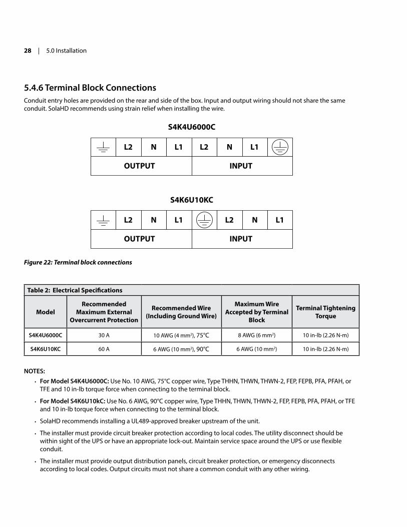
5.4.6 Terminal Block ConnectionsConduit entry holes are provided on the rear and side of the box. input and output wiring should not share the same conduit. SolaHD recommends using strain relief when installing the wire.
L2 N L1 L2 N L1
OUTPUT INPUT
L2 N L1 L2 N L1
OUTPUT INPUT
S4K4U6000C
S4K6U10KC
Figure 22: Terminal block connections
Table 2: Electrical Specifications
ModelRecommended
Maximum External Overcurrent Protection
Recommended wire (Including ground wire)
Maximum wireAccepted by Terminal
Block
Terminal Tightening Torque
S4K4U6000C 30 A 10 AWG (4 mm2), 75°C 8 AWG (6 mm2) 10 in-lb (2.26 n-m)
S4K6U10KC 60 A 6 AWG (10 mm2), 90°C 6 AWG (10 mm2) 10 in-lb (2.26 n-m)
NOTES:• For Model S4K4U6000C: Use no. 10 AWG, 75°C copper wire, Type THHn, THWn, THWn-2, FEP, FEPB, PFA, PFAH, or
TFE and 10 in-lb torque force when connecting to the terminal block.
• For Model S4K6U10kC: Use no. 6 AWG, 90°C copper wire, Type THHn, THWn, THWn-2, FEP, FEPB, PFA, PFAH, or TFE and 10 in-lb torque force when connecting to the terminal block.
• SolaHD recommends installing a UL489-approved breaker upstream of the unit.
• The installer must provide circuit breaker protection according to local codes. The utility disconnect should be within sight of the UPS or have an appropriate lock-out. maintain service space around the UPS or use flexible conduit.
• The installer must provide output distribution panels, circuit breaker protection, or emergency disconnects according to local codes. Output circuits must not share a common conduit with any other wiring.
S4KC SEriES USEr mAnUAL | 29
6.0 Configuration ProgramThe final step of installation may require custom configuration of your UPS using the enclosed configuration program (located on the CD). Some configuration settings may be changed only while the UPS is off. These settings should be set before the UPS is put into service powering critical loads.
6.1 Configuration Program Features• Select L–n output voltages to match local voltages.
• Enable/Disable Auto-restart.
• Select frequency converter operation with a fixed output frequency of 50 or 60 Hz.
• Set the Low Battery alarm time to a value of 2 to 30 minutes.
• Enable/Disable the Auto-Battery Test.
• Set the Auto-Battery Test for 7, 14, 21, or 28 days.
• Specify the number of external battery cabinets connected to the UPS to adjust the remaining backup time calcula-tions reported by software products.
• modify the shutdown setting of the terminal block.
6.1.1 What You Will Needin addition to the S4KC UPS, you will need the configuration program (located on the CD) and USB cable; both are included in the UPS accessory box. A Windows 95® or later computer, desktop, or laptop with a USB port is also required to set up and run the configuration program.

30 | 7.0 Controls & indicators
7.0 Controls & indicators
Battery Level indicators
L1 Load Level indicators
L2 Load Level indicators
Bypass indicatorInverter indicator
On/Alarm Silence/Manual Battery Test button
Standby/ManualBypass button
Fault indicator
Ac Input indicatorBattery indicator
Figure 23: Operation and display panel
7.1 On/Alarm Silence/Manual Battery Test ButtonThis button controls output power to connected load(s) and has three functions:
• On: Pressing this button for 4 seconds will start the UPS.
• Alarm Silence: To silence alarms, press this button for at least one second. After the alarm is silenced, the S4KC will reactivate the alarm system to alert of additional problems.
NOTE: The Low Battery and Bypass reminder alarms CAnnOT be silenced.
• Manual Battery Test: To initiate a manual battery test, press the On button for at least 1 second while operating from utility power with no alarm conditions present. if only three of the five Battery LEDs illuminate, allow the UPS to recharge the batteries for 24 hours. After 24 hours, retest the batteries.
After the batteries have been retested, if only three of the five Battery LEDs illuminate, please contact SolaHD Tech-nical Support at (800) 377-4384 or by e-mail at [email protected].
S4KC SEriES USEr mAnUAL | 31
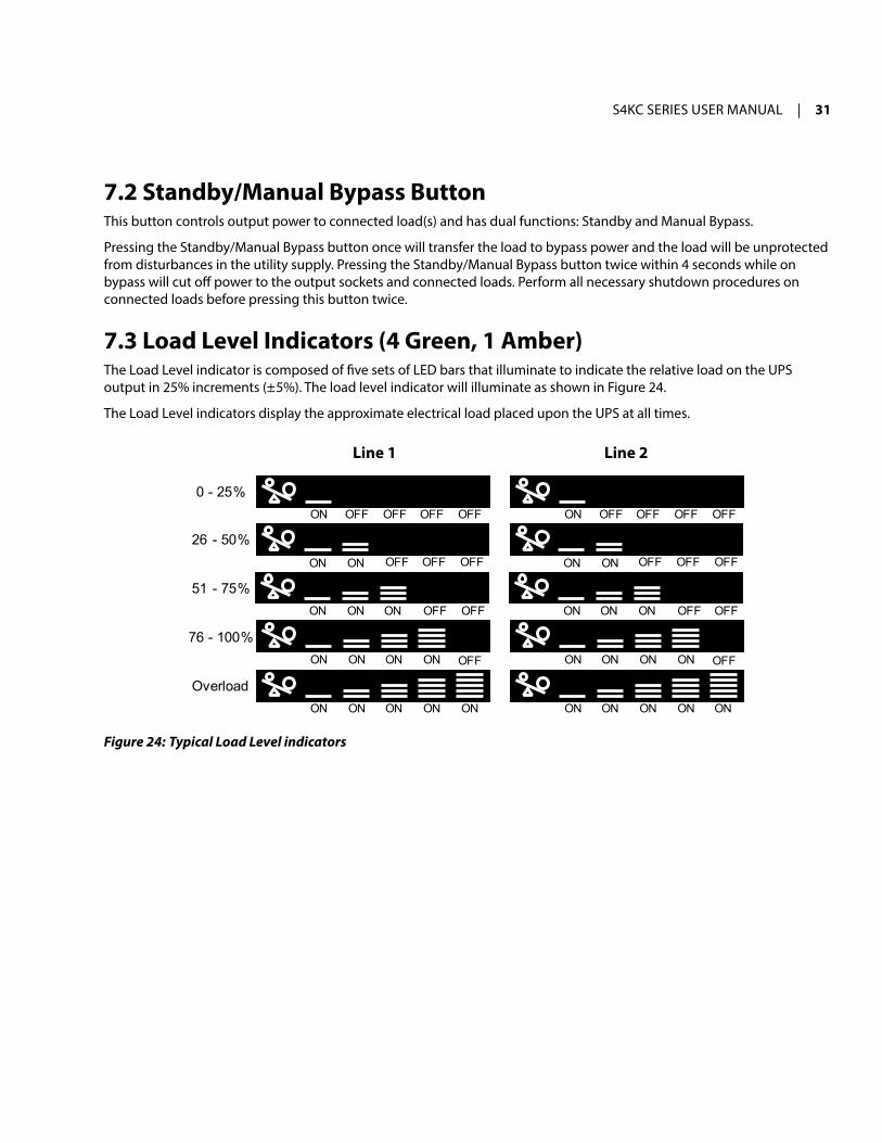
7.2 Standby/Manual Bypass ButtonThis button controls output power to connected load(s) and has dual functions: Standby and manual Bypass.
Pressing the Standby/manual Bypass button once will transfer the load to bypass power and the load will be unprotected from disturbances in the utility supply. Pressing the Standby/manual Bypass button twice within 4 seconds while on bypass will cut off power to the output sockets and connected loads. Perform all necessary shutdown procedures on connected loads before pressing this button twice.
7.3 Load Level Indicators (4 green, 1 Amber)The Load Level indicator is composed of five sets of LED bars that illuminate to indicate the relative load on the UPS output in 25% increments (± 5%). The load level indicator will illuminate as shown in Figure 24.
The Load Level indicators display the approximate electrical load placed upon the UPS at all times.
0 - 25%
Overload
76 - 100%
51 - 75%
26 - 50%
ON OFF OFF OFF OFF
ON ON OFF OFF OFF
ON ON ON OFF OFF
ON ON ON ON OFF
ON ON ON ON ON
ON OFF OFF OFF OFF
ON ON OFF OFF OFF
ON ON ON OFF OFF
ON ON ON ON OFF
ON ON ON ON ON
Line 2Line 1
Figure 24: Typical Load Level indicators

32 | 7.0 Controls & indicators
7.4 Battery Level Indicators (5 green)The Battery Level indicator is composed of five sets of LED bars that illuminate and flash to indicate the battery capacity level. The S4KC battery capacity level is shown in 20% increments (± 5%). The Battery Level indicators will illuminate as shown in Figure 25. The Battery Level indicators display approximate battery capacity at all times.
The S4KC is equipped with automatic and remote battery test features. The default setting is for the automatic test to occur every 14 days (this option is user-configurable) if utility power has not been interrupted. Should the battery fail this test, the red Fault indicator LED along with the A and C Diagnostic LEDs will illuminate and an alarm will sound (refer to “11.0 Troubleshooting”). The remote test feature functions with multiLink and can remotely initiate the battery test.
0 - 20%
FullyCharged
81 - 100%
61 - 80%
41 - 60%
21 - 40%
ON ON ON ON ON
ONONONONON
OFFON ON ON ON
ON ON OFF OFF OFF
ON OFF OFF OFF OFF
ONON ON OFF OFF
Discharging
Flash OFF OFF OFF OFF
OFFON ON ON Flash
ONON Flash OFF OFF
ON Flash OFF OFF OFF
FlashONONONON
ON ON ON ON ON
Charging
Figure 25: Battery Level indicators

S4KC SEriES USEr mAnUAL | 33
7.5 UPS Status IndicatorsUPS status is indicated by five symbols: Fault indicator, Ac input indicator, Battery indicator, inverter indicator, and Bypass indicator. Table 3 shows the symbols and their meanings.
Table 3: UPS Status Indicators
UPS Status Indicator Icon Color Description
Fault indicator red On if the UPS has detected a fault; off if there is no fault.
Ac Input indicator Green On when the utility input power is normal; off during utility failure; flashing when utility power is outside the specifications.
Battery indicator Amber On when the battery is supplying power; off when the battery is not supplying power.
Inverter indicator Green On when the inverter is supplying power; off when the inverter is not supplying power; flashing when utility power is outside the specifications.
Bypass indicator Amber On when the bypass is supplying power; off when the inverter is supplying power; flashing when utility power is outside the specifications.

34 | 8.0 Operation
8.0 OperationNOTE: The S4KC’s battery is fully charged before delivery, but some charge will be lost during storage and shipping. To ensure that the battery has adequate reserve power to protect the connected load, charge the battery for 3 hours before putting the UPS into service.
8.1 Startup Checklist for the S4KCBefore starting the UPS, perform these checks:1. Check that the input/output cables and loads are connected properly and reliably.
2. Check that all of the battery cables are connected properly.
3. Check that the communication cables are connected properly.
8.2 Initial Startup & Electrical Checks1. Verify that the input/output circuit breakers are OFF.
2. During initial system checks, disconnect all loads.
3. inspect all wiring, cables, and connections.
4. if external battery cabinets are used, verify that the battery cables are fully inserted in the sockets.
5. Place the manual bypass breaker in the ByPASS position.
6. Turn on the branch circuit disconnect to apply voltage to the input terminal block.
7. Using a voltmeter, verify the expected L1–n–L2 voltage. (refer to “12.0 Specifications”.) Verify that the same voltages are measured at the output terminals. The Bypass LED (by the switch) will illuminate.
8. After verifying proper input voltage to the UPS terminal block, turn off the branch circuit power, close all access panels to the distribution box and reapply input power.
9. Close the input circuit breaker located on the distribution box. The green Ac input LED should illuminate on the front panel.
10. Press the On button for 4 seconds. After several seconds, the UPS On LED will illuminate continuously. if the batteries are determined to be charged above 80%, an automatic battery test will run for about 15 seconds.
11. Close the output circuit breaker on the rear of the power distribution box. The light by the input breaker will illuminate.
12. return the breaker to the inVErTEr position. The output terminal block will be powered at this time.
13. Connect all loads for normal operation.
8.3 Manual Battery TestTo initiate a manual battery test, press the On/Alarm Silence/manual Battery Test button for at least half a second while operating from utility power with no alarm conditions present.
• if only the first two of the five LED segments illuminate, allow the UPS to recharge the batteries for 24 hours. retest the batteries after 24 hours of charging.
• After the batteries have been retested, if only two of the five Battery LEDs illuminate, contact SolaHD Technical Support at (800) 377-4384 or by e-mail at [email protected].

S4KC SEriES USEr mAnUAL | 35
• if zero of the five Battery LEDs illuminate during a manual battery test, check the battery connection and allow the UPS to recharge the batteries for 1 hour, then initiate a manual battery test again.
• if zero of the five Battery LEDs illuminate during the second manual battery test, replace the batteries and contact SolaHD Technical Support at (800) 377-4384 or by e-mail at [email protected].
8.4 Put the S4KC in Manual BypassPress the Standby/manual Bypass button and hold it for about 2 seconds while the UPS is in Utility (Ac) mode. The UPS will transfer the connected loads to the internal bypass. if the internal bypass is not available because of utility power problems, pressing this button once will be ignored. Bypass operation is indicated by an audible alarm and illuminated amber Bypass indicator.
8.5 Shut Down the S4KC1. Transfer the UPS to manual bypass by pressing the Standby/manual Bypass button once (hold it for about 2 seconds).
if manual bypass is not available, disregard the first step.
2. Press the Standby/manual Bypass button twice within 4 seconds (hold the button down for about 2 seconds each time) to shut down the UPS.
3. Power to the connected loads is now off.
8.6 Disconnecting Input Power from the S4KC1. After the UPS has been shut down as detailed in “8.5 Shut Down the S4KC”, turn off the output circuit breaker.
2. Wait 30 seconds and verify that all indicators have turned off and the fan has stopped; this indicates that the power-off is complete.
3. if the UPS has an external battery cabinet, turn the external battery cabinet breaker switch to the OFF position.
4. After powering off the UPS, the UPS ceases output and the load is powered off.
8.7 Maintenance Bypassmaintenance Bypass mode is used when maintenance or UPS replacement is required.
To place the unit in Maintenance Bypass Mode:1. Place the UPS on internal bypass. This may be done by one of the following methods:
a. Press the OFF button on the front panel one time. (The unit will go into static bypass alarm.)b. Slide the bracket away from the maintenance bypass breaker on the rear of the UPS. This requires loosening the
captive screw and sliding the bracket up and away from the maintenance bypass breaker. (The unit will go into static bypass alarm.)
2. Verify that the amber LED (located on the rear of the UPS above the maintenance bypass breaker, labeled “mainte-nance bypass available”) is illuminated.
3. move the maintenance bypass breaker on the rear of the UPS to the ByPASS position. This requires loosening the captive screw and sliding the bracket up and away from the maintenance bypass breaker.
! wARNINgBefore switching the maintenance bypass breaker, always verify that the amber LED on the rear of the UPS is illumi-nated. If the maintenance bypass breaker is closed while the UPS is operating on inverter, bypass power will feed back to the inverter. This will trigger the UPS alarm, drop the load, and could potentially damage the inverter.

36 | 9.0 Communication
9.0 Communication
9.1 Communication Interface PortThe S4KC has a terminal block on the rear of the unit. Several signals are provided on this port and are assigned as follows.
9.2 Terminal Block CommunicationThe terminal block includes eight PinS, as shown in Figure 26.
1 2 3 4Low Battery
Warning On Battery
Warning Any ModeShutdown
Battery ModeShutdown
Figure 26: Terminal block communication terminals
9.2.1 Any Mode ShutdownThe purpose of Any mode Shutdown is to shut down the UPS output by turning off the rectifier, inverter, and static switch so that there is no power to the loads. Activation of the Any mode Shutdown will be logged as an event in the event history log.
Any mode Shutdown can be operated locally or remotely:
• Local Any mode Shutdown can be performed by shorting the Pins in Set 3.
• Remote Any mode Shutdown can be performed using a switch connected to the Pins in Set 3 and mounted at a remote location.
NOTES:• Use the options menu in the configuration program to set the remote Power Off to either a nO or nC contact at the
Any mode Shutdown Pins.
• The current limited source for the opto coupler (+12 Vdc, 50 mA) will be available from the UPS.
• The connection to UPS for remote connection will be via terminal block connector.
• Any mode Shutdown wiring must conform to all national, regional, and local wiring codes and laws.
! wARNINgWhen the auto-enable output option is selected and the UPS output is disabled using the PINs in Set 3, the S4KC’s output can turn on automatically and without warning if the Set 3 PIN connection is changed.
S4KC SEriES USEr mAnUAL | 37
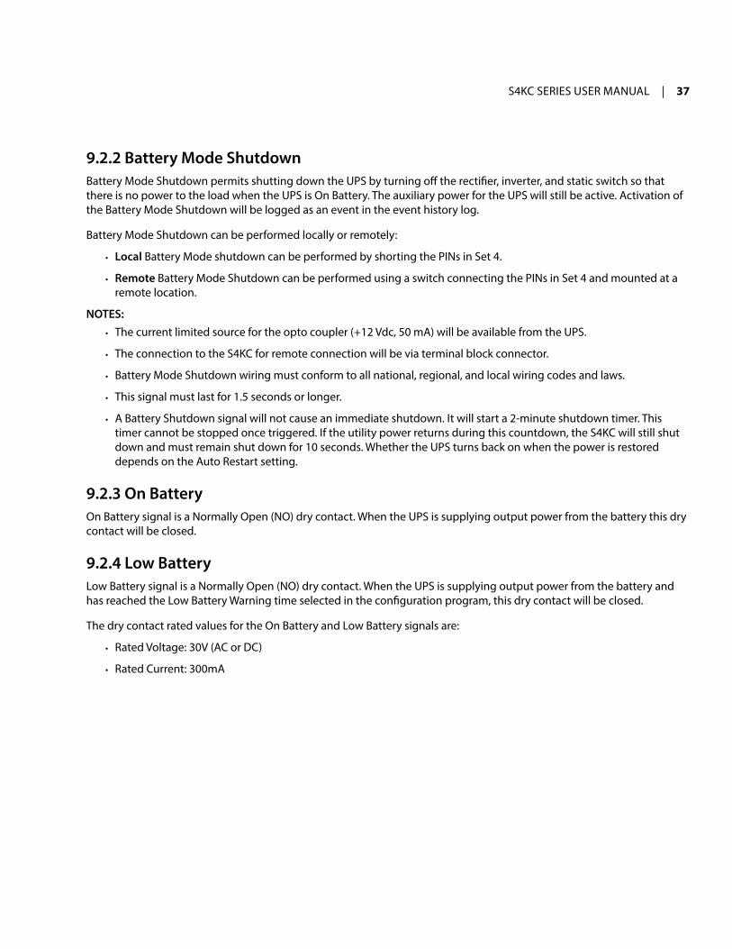
9.2.2 Battery Mode ShutdownBattery mode Shutdown permits shutting down the UPS by turning off the rectifier, inverter, and static switch so that there is no power to the load when the UPS is On Battery. The auxiliary power for the UPS will still be active. Activation of the Battery mode Shutdown will be logged as an event in the event history log.
Battery mode Shutdown can be performed locally or remotely:
• Local Battery mode shutdown can be performed by shorting the Pins in Set 4.
• Remote Battery mode Shutdown can be performed using a switch connecting the Pins in Set 4 and mounted at a remote location.
NOTES:• The current limited source for the opto coupler (+12 Vdc, 50 mA) will be available from the UPS.
• The connection to the S4KC for remote connection will be via terminal block connector.
• Battery mode Shutdown wiring must conform to all national, regional, and local wiring codes and laws.
• This signal must last for 1.5 seconds or longer.
• A Battery Shutdown signal will not cause an immediate shutdown. it will start a 2-minute shutdown timer. This timer cannot be stopped once triggered. if the utility power returns during this countdown, the S4KC will still shut down and must remain shut down for 10 seconds. Whether the UPS turns back on when the power is restored depends on the Auto restart setting.
9.2.3 On BatteryOn Battery signal is a normally Open (nO) dry contact. When the UPS is supplying output power from the battery this dry contact will be closed.
9.2.4 Low BatteryLow Battery signal is a normally Open (nO) dry contact. When the UPS is supplying output power from the battery and has reached the Low Battery Warning time selected in the configuration program, this dry contact will be closed.
The dry contact rated values for the On Battery and Low Battery signals are:
• rated Voltage: 30V (AC or DC)
• rated Current: 300mA

38 | 9.0 Communication
9.3 UPS IntelliSlot Communication CardsThe intelliSlot port accepts the following optional cards:
• SNMPWEB Card. The intelliSlot SnmP Card provides SnmP monitoring and control of the UPS across the network.
• IS-RELAY. The intelliSlot relay Card provides dry contact relay outputs for custom-wired applications and delivers support for built-in shutdown for AS/400 systems.
Follow instructions provided with the intelliSlot card to configure multiLink, the UPS, or any additional ancillary product for the S4KC. These instructions are also available at www.multilink.com.
9.3.1 MultiLinkmultiLink continually monitors the UPS and can shut down your computer or server in the event of an extended power failure. it can also be configured for use without the USB cable when the intelliSlot SnmP/Web card is installed in the UPS. Additionally, multiLink can be configured to coordinate shutdown across the network with other computers running multiLink when you purchase a multiLink License Kit. For more information about the intelliSlot SnmP/Web Card and multiLink License Kits, visit our Web site (www.solahd.com) or contact your SolaHD representative.
9.4 Remote Emergency Power OffThe UPS is equipped with a remote Emergency Power Off (rEPO) connector.
The user must supply a means of interfacing with the rEPO circuit to allow disconnecting the UPS input feeder breaker to remove all sources of power to the UPS. All connected equipment must comply with national and local wiring codes and regulations.
1 2
Normally closed switch system (fail-safe)
UPS ships with REPO jumperinstalled allowing the UPS to operate.
Opening the REPO connection will disable the UPS.Manual restart using the front panel is required
after the REPO connection is closed again.
1 2
Figure 27: REPO switch connection diagram
! CAUTIONTo maintain safety (SELV) barriers and electromagnetic compatibility, signal cables should be shielded and run separately from power cables.

S4KC SEriES USEr mAnUAL | 39
10.0 maintenanceThis section describes replacing the internal battery pack, precautions, checking the UPS status, and checking UPS functions.
10.1 Replacing the Internal Battery PackThe S4KC is designed to allow service personnel to safely replace the internal battery packs. The battery packs may also be replaced by a properly trained user when the UPS is installed in a restricted access area such as a rack. Please read the “Battery Safety notes” on page 7 before proceeding. Contact your local dealer or SolaHD representative to obtain the part number and pricing of the appropriate replacement battery packs.
10.1.1 Battery Replacement Procedures1. remove the screws securing the individual front metal bezels.
2. Slide the individual front metal bezels until the locking tabs release.
3. remove the front metal bezels from the UPS and set them aside for reassembly.
4. remove the six screws on the battery door.
5. Set the battery door and all screws aside for reassembly.
Front metal bezel
Battery door
S4K6U10KC model shown;S4K4U6000C arrangementis the same, except smaller
Figure 28: Removing the front metal bezels and battery door

40 | 10.0 maintenance
6. Gently pull the battery wires out and disconnect the battery plugs and receptacles, as shown in Figure 29.
Battery plug and receptacle
Battery plugand receptacle
S4K6U10KC model shown;S4K4U6000C arrangementis the same, except smaller
Figure 29: Disconnecting the battery plug and receptacle (front view)
7. Grasp the battery handle and pull one of the internal battery packs out of the UPS, as shown in Figure 30. repeat this step if both battery packs will be replaced. Each model has two battery packs.
Internalbatterypack (1 of 2)
Pull out with battery handle
S4K4U6000C S4K6U10KC
Pull out with battery handle
Internalbatterypack (1 of 2)
Figure 30: Pulling out the battery packs
8. Unpack the new internal battery pack. Take care not to damage the packaging. Compare the new and old internal battery packs to make sure they are the same type and model. if they are the same, proceed with Step 7; if they are different, stop and contact your SolaHD representative or SolaHD Technical Support immediately.
9. Line up and slide in the new internal battery pack.
10. repeat Steps 6 and 7 if replacing both battery packs. Each model has two battery packs.
11. reconnect the battery plugs and battery receptacles.
12. Gently push the battery wire into the UPS battery compartment.
13. reattach the front battery door with the six screws.
14. reattach the front metal bezels to the UPS.
NOTE: The internal battery pack is hot-swappable. However, caution should be exercised as the load is unprotected from disturbances and power failures during this procedure. Do not replace the battery pack while the UPS is operating in Battery mode. This will result in a loss of output power and will drop the connected load.

S4KC SEriES USEr mAnUAL | 41
10.2 Battery ChargingThe batteries are valve-regulated, non-spillable, lead acid and should be kept charged to attain their design life. The S4KC charges the batteries continuously when it is connected to the utility input power.
if the S4KC will be stored for a long time, SolaHD recommends connecting the UPS to input power for at least 24 hours every four to six months to ensure full recharge of the batteries.
10.3 PrecautionsAlthough the S4KC has been designed and manufactured to ensure personal safety, improper use can result in electrical shock or fire. To ensure safety, observe the following precautions:
• Turn off and unplug the S4KC before cleaning it.
• Wear rubber gloves, boots, and safety glasses.
• Clean the UPS with a soft, dry cloth. Do not use liquid or aerosol cleaners.
• never block or insert any objects into the ventilation holes or other openings of the UPS.
• Do not place the S4KC power cord where it might be damaged.
10.4 Checking UPS StatusSolaHD recommends checking the UPS operation status every six months.
• Check whether the UPS is faulty. is the Fault indicator on? is the UPS sounding an alarm?
• Check whether the UPS is operating in Bypass mode. normally, the UPS operates in normal mode. if it is operating in Bypass mode, stop and contact your local SolaHD representative or SolaHD Technical Support.
• Check whether the battery is discharging. When the utility input is normal, the battery should not discharge. if the UPS is operating in Battery mode, stop and contact your SolaHD representative or SolaHD Technical Support.
10.5 Checking UPS FunctionsNOTE: UPS function check procedures may interrupt power supply to the connected load. Back up the load data before conducting the UPS functions check.
SolaHD recommends checking the UPS functions once every six months.
Procedures are as follows:1. Press the Standby/manual Bypass button to check whether the alarm and indicators are normal.
2. Press the On/Alarm Silence/manual Battery Test button to check again whether the indicators are on and the UPS is operating normally.
3. Press the On/Alarm Silence/manual Battery Test button for 3 seconds after inverter mode. The UPS should initiate a battery self-test. Check to determine whether the battery is operating normally. if not, stop and contact your SolaHD representative or SolaHD Technical Support.

42 | 10.0 maintenance
10.6 Replacing the Power Module on S4K6U10KC! CAUTION
The UPS must be switched to manual bypass before replacing the power module.
NOTICE: During the procedure, the connected load will not be protected from power disturbances, such as spikes, sags, and failure.
To remove the UPS power module without shutting off power to the connected load:1. Place the UPS on internal bypass. This may be done by any of the three following methods:
a. Press the OFF button on the front panel one time.
b. Slide the bracket away from the manual bypass breaker on the rear of the UPS; this requires loosening the captive screw and sliding the bracket away from the manual bypass breaker.
c. remove the front grille covering the power module.
2. move the manual bypass breaker on the rear of the UPS to the ByPASS position; this requires loosening the captive screw and sliding the bracket away from the manual bypass breaker (see Figure 7).
3. Open the input circuit breaker on the rear of the UPS (see Figure 7).
4. Open the output circuit breaker on the rear of the UPS (see Figure 7).
5. remove the top two front metal bezels by pulling them forward.
6. remove the power module cover grille and the battery cover grille.
7. Disconnect the slotted battery connectors from the internal battery packs.
8. if additional external batteries are used, disconnect the two external battery connectors.
9. Slide the power module restraint lever up and out of the locked position.
10. Slide the power module out of the front, supporting its weight as it is withdrawn.
Power module
Figure 31: Removing the power module from S4K6U10KC

S4KC SEriES USEr mAnUAL | 43
11. insert the replacement UPS power module.
12. Slide the power module restraint lever back into the locked position.
NOTE: The power module restraint lever must be fully engaged for the UPS to operate in normal mode.
13. reconnect the slotted internal battery connectors.
14. reconnect the external battery cables, if used.
15. reattach both front cover grilles.
16. reattach the front metal bezels.
17. Close the input circuit breaker on the rear of the UPS (see Figure 7).
18. Close the output circuit breaker on the rear of the UPS (see Figure 7).
19. move the manual bypass breaker on the rear of the UPS back to the inVErTEr position (see Figure 7).
20. Slide the bracket back next to the manual bypass breaker and tighten its captive screw.
21. Press the On button on the front panel one time to return the UPS to normal mode operation (see Figure 24).

44 | 11.0 Troubleshooting
11.0 TroubleshootingThis section indicates various UPS symptoms a user may encounter and troubleshooting steps in the event the UPS develops a problem. Use the following information to determine whether external factors caused the problem and how to remedy the situation.
11.1 UPS SymptomsThe following symptoms indicate the S4KC is malfunctioning:
• The relative indicators will illuminate, indicating the UPS detected a problem.
• An alarm will sound, indicating that the UPS requires attention.
11.1.1 Indicatorsin addition to the Fault indicator being illuminated, one or more of LED segments of Battery Level indicator will also be illuminated to provide a diagnostic aid to the user, as shown in Figure 32. The descriptions are listed in Table 4.
A B C D EFigure 32: Battery Level indicator
Table 4: Indicator Descriptions
Indicator Diagnosis Audible Alarm
A–E On bypass from output overload Half-second beep every half second
A On bypass due to overtemperature condition 1-second beep every 4 seconds
B On bypass due to dc bus overvoltage 1-second beep every 4 seconds
C On bypass due to dc/dc power supply failure 1-second beep every 4 seconds
D PFC failure 1-second beep every 4 seconds
E On bypass due to inverter failure 1-second beep every 4 seconds
A & B UPS failure (includes dual-fan failure, single-fan failure under certain conditions, and battery charger failure) Continuous alarm
A & C UPS failed battery test 2-second beep every 60 seconds
A & D maintenance bypass switch on Continuous alarm
A & E Bypass feedback 1-second beep every 4 seconds
B & C rEPO One quater-second beep at quater-second intervals
B & E Short circuit on the output n/a
C & E UPS shutdown by command from communication (USB port or intellislot port) n/a

S4KC SEriES USEr mAnUAL | 45
Table 4: Indicator Descriptions
Indicator Diagnosis Audible Alarm
Utility LED flash L–n reverse n/a
Battery indicator flashing internal battery source not available; check battery connection, power down, and reboot the UPS Continuous alarm
Bypass indicator flashing Utility power voltage or frequency is out of tolerance; bypass is unavailable n/a
NOTE: A–E indicators are shown in Figure 32.
11.1.2 Audible AlarmAn audible alarm will sound in conjunction with the visual indicators to indicate a change in UPS operating status. The audible alarm will sound as described in Table 5.
Table 5: Audible Alarm Descriptions
Condition Alarm
Battery discharge Half-second beep every 10 seconds
Low battery Two half-second beeps every 5 seconds
UPS fault, load on bypass 1-second beep every 4 seconds
UPS fault, no power to load Continuous
Overload Half-second beep every half second
Battery replacement 2-second beep every 60 seconds
Battery loss Continuous
Wiring problem (loss of proper grounding for UPS) Continuous
Bypass reminder 1-second beep every 2 minutes

46 | 11.0 Troubleshooting
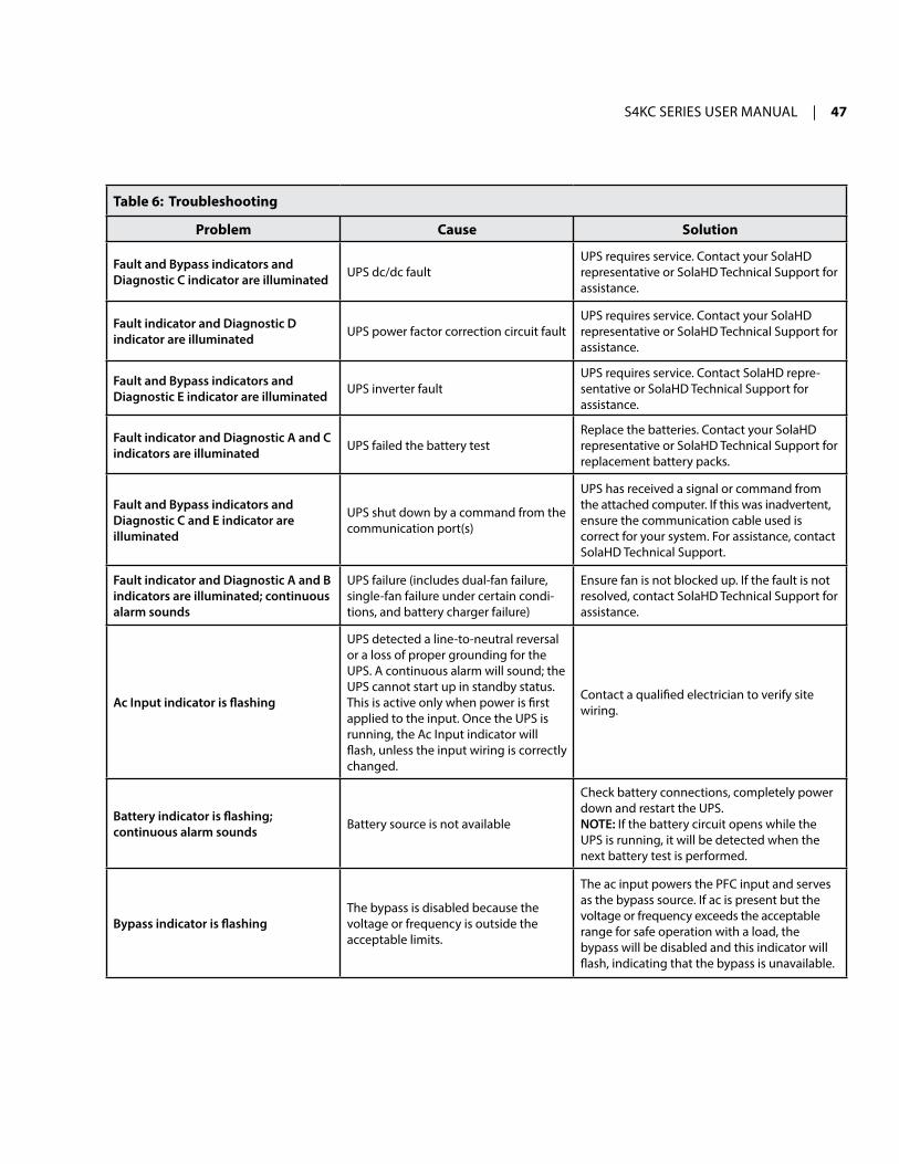
11.2 Troubleshootingin the event of an issue with the UPS, refer to Table 6 to determine the cause and solution. if the issue persists, contact SolaHD Technical Support at (800) 377-4384 or by e-mail at [email protected].
When reporting an issue to Technical Support, please include the UPS model number and serial number. This information is located on the top panel of the UPS.
Table 6: Troubleshooting
Problem Cause Solution
UPS fails to start when the On/Alarm Silence/Manual Battery Test button is pressed
UPS is short-circuited or overloaded
Ensure the UPS is off. Disconnect all loads and ensure nothing is lodged in the output receptacles. Ensure loads are not defective or shorted internally.
Battery indicator is illuminated
UPS is not plugged in UPS is operating from Battery mode. Ensure UPS is securely plugged into the wall receptacle.
UPS input protection fuse has blown/opened
UPS is operating from Battery mode. Save data and close applications. replace UPS input fuse, then restart the UPS.
Utility power is out of toleranceUPS is operating from Battery mode. Save data and close applications. Ensure utility supply voltage is within acceptable limits for the UPS.
UPS has reduced battery backup time
Batteries are not fully charged Keep the UPS plugged in continuously for at least 24 hours to recharge the batteries.
UPS is overloaded Check Load Level indicator and reduce the load on the UPS.
Batteries may not be able to hold a full charge due to age
replace the batteries. Contact your SolaHD representative or SolaHD Technical Support for replacement battery packs.
Fault and Bypass indicators and all LED segments of the Battery Level indicator are illuminated
UPS is overloaded or the load is faulty
Check the Load Level indicator and remove non-essential loads. recalculate the load and reduce the number of loads connected to the UPS. Check the load for faults.
Fault and Bypass indicators and Diagnostic A indicator are illuminated
UPS shutdown due to overtemperature condition; load is on bypass power
Ensure the UPS is not overloaded, ventila-tion holes are not blocked, or room ambient temperature is not excessive. Wait 30 minutes to allow the UPS to cool, then restart the UPS. if the UPS cannot restart, contact your SolaHD representative or SolaHD Technical Support for assistance.
Fault and Bypass indicators and Diagnostic B indicator are illuminated UPS internal dc bus overvoltage
UPS requires service. Contact your SolaHD representative or SolaHD Technical Support for assistance.
S4KC SEriES USEr mAnUAL | 47
Table 6: Troubleshooting
Problem Cause Solution
Fault and Bypass indicators and Diagnostic C indicator are illuminated UPS dc/dc fault
UPS requires service. Contact your SolaHD representative or SolaHD Technical Support for assistance.
Fault indicator and Diagnostic D indicator are illuminated UPS power factor correction circuit fault
UPS requires service. Contact your SolaHD representative or SolaHD Technical Support for assistance.
Fault and Bypass indicators and Diagnostic E indicator are illuminated UPS inverter fault
UPS requires service. Contact SolaHD repre-sentative or SolaHD Technical Support for assistance.
Fault indicator and Diagnostic A and C indicators are illuminated UPS failed the battery test
replace the batteries. Contact your SolaHD representative or SolaHD Technical Support for replacement battery packs.
Fault and Bypass indicators and Diagnostic C and E indicator are illuminated
UPS shut down by a command from the communication port(s)
UPS has received a signal or command from the attached computer. if this was inadvertent, ensure the communication cable used is correct for your system. For assistance, contact SolaHD Technical Support.
Fault indicator and Diagnostic A and B indicators are illuminated; continuous alarm sounds
UPS failure (includes dual-fan failure, single-fan failure under certain condi-tions, and battery charger failure)
Ensure fan is not blocked up. if the fault is not resolved, contact SolaHD Technical Support for assistance.
Ac Input indicator is flashing
UPS detected a line-to-neutral reversal or a loss of proper grounding for the UPS. A continuous alarm will sound; the UPS cannot start up in standby status.This is active only when power is first applied to the input. Once the UPS is running, the Ac input indicator will flash, unless the input wiring is correctly changed.
Contact a qualified electrician to verify site wiring.
Battery indicator is flashing; continuous alarm sounds Battery source is not available
Check battery connections, completely power down and restart the UPS.NOTE: if the battery circuit opens while the UPS is running, it will be detected when the next battery test is performed.
Bypass indicator is flashingThe bypass is disabled because the voltage or frequency is outside the acceptable limits.
The ac input powers the PFC input and serves as the bypass source. if ac is present but the voltage or frequency exceeds the acceptable range for safe operation with a load, the bypass will be disabled and this indicator will flash, indicating that the bypass is unavailable.

48 | 12.0 Specifications
12.0 Specifications
Table 7: UPS Specifications
ParametersModel
S4K4U6000C S4K6U10KC
Rating 4800 W/6000 VA 9000 W/10000 VA
DIMENSIONS, w x D x H, in. [mm]
Unit 6.8 x 26.1 x 16.9 [173 x 662 x 430] 10.3 x 26.5 x 16.9 [261 x 672 x 430]
Shipping 13.2 x 33.1 x 26.1 [336 x 842 x 662] 16.7 x 32.8 x 24.1 [424 x 832 x 612]
wEIgHT, lb. [kg]
Unit (including internal batteries) 132.0 [59.9] 220.5 [100.1]
Shipping (batteries ship separately) 70.5 [32.0] 92.6 [42.0]
INPUT AC PARAMETERS
Nominal Operating Frequency 50 or 60 Hz (Factory default is 60 Hz)
Factory Default Vac 120/208 Vac @ 120 degrees
L1–L2 Factory Default Input Phase Angle 120 degrees
Allowable Input Phase Angle 120, 180, 240 degrees; auto-sensing on application of alternating current (restrictions for L–n voltage other than 120 Vac)
Factory Default L1–N, L2–N Vac 120 Vac nominal
User Configurable L1–N, L2–N Vac 100/110/115/120 Vac (Can be modified with configuration program)
Input Frequency w/o Battery Operation 40–70 Hz
Input Power Connection Hardwire terminal block 3W + G (L–L–n–G)
L1–N, L2–N Maximum Allowable Vac 150 Vac
OUTPUT AC PARAMETERS
Factory Default Vac 120/208 Vac @ 120 degrees
L1–L2 Factory Default Output Phase Angle 120 degrees
Allowable Output Phase Angle 120, 180, 240 degrees; auto-sensing on initial application of input alternating current
Factory Default L1–N, L2–N Vac 120 Vac nominal
User Configurable L1–N, L2–N Vac 100/110/115/120 Vac, ± 2%
L1–N, L2–N Operating Load Range
105% to 130% 1 minute
131% to 150% 10 seconds
151% to 200% 1 second
>200% (impact load) At least 5 cycles

S4KC SEriES USEr mAnUAL | 49
Table 7: UPS Specifications
ParametersModel
S4K4U6000C S4K6U10KC
ByPASS PROTECTION LIMITS
Disable Bypass Operation if input voltage exceeds ±15% of the nominal voltage
Re-enable Bypass Operation if input voltage returns to within ±10% of nominal output voltage
Disable Bypass Operation When the input frequency prevents synchronous operation
ENVIRONMENTAL REqUIREMENTS
Operating Temperature 0°C to +40°C [+32°F to +104°F]; See Table 8 for operating temperature parameters
Storage Temperature -15°C to +50°C [+5°F to +122°F]
Relative Humidity 0% to 95%, non-condensing
Operating Elevation Up to 10,000 ft. [3,000 m]
Audible Noise <55 dBA @ 3.2 ft. [1 m] rear; <50 dBA @ 3.2 ft. [1 m] front & sides
AgENCy
Safety UL1778, cUL Listed, not for use in a computer room as defined in the standard for the protect of Electronic Computer/Data Processing Equipment AnSi/nFPA 75
RFI/EMI FCC Part 15, Subpart B, Class A, FCC Class A
Surge Immunity iEEE/AnSi C62.41 Category A & B
Transportation iSTA Procedure 1A
Table 8: Operating Temperature Parameters
Ambient Temperature Maximum Output Power Factor Derating at Maximum Load
<+30°C [<+86°F] 100%
+30°C to +40°C [+86°F to +104°F] 90%

50 | 12.0 Specifications
Table 9: Internal Battery Specifications
ParametersModel Number
S4K144INTBATC S4K288INTBATC
Used with 6000 VA models 10000 VA models
DIMENSIONS, w x D x H, in. [mm]
Unit 2.8 x 19.3 x 8.1 [70 x 490 x 206] 5.3 x 19.7 x 8.1 [135 x 500 x 207]
Shipping 12.2 x 23.7 x 10.3 [310 x 602 x 262] 12.2 x 23.9 x 9.5 [310 x 607 x 242]
wEIgHT, lb. [kg]
Unit 75.8 [34.4] 71.1 [32.3]
Shipping 81.1 [36.8] 76.4 [34.7]
BATTERy PARAMETERS
Type Valve-regulated, non-spillable, flame retardant, lead acid
Qty x V x Rating 2 x 6 x 12 V x 8.5 Ah 2 x 12 x 12 V x 8.5 Ah
Battery Mfr./Part Number Panasonic/UP-rW1245; CSB/Hr 1234W F2
Backup Time See Table 13
Recharge Time 3 hours to 90% capacity after full discharge into 100% load
ENVIRONMENTAL REqUIREMENTS
Operating Temperature 0°C to +40°C [+32°F to +104°F]; See Table 8 for operating temperature parameters
Storage Temperature -15°C to +50°C [+5°F to +122°F]
Relative Humidity 0% to 95%, non-condensing
Operating Elevation Up to 10,000 ft. [3,000 m]
AgENCy
Safety UL1778, cUL Listed, not for use in a computer room as defined in the standard for the protect of Electronic Computer/Data Processing Equipment AnSi/nFPA 75
RFI/EMI FCC Part 15, Subpart B, Class A
Transportation iSTA Procedure 1A

S4KC SEriES USEr mAnUAL | 51
Table 10: External Battery Cabinet Specifications
ParametersModel Number
S4K144BATC S4K288BATC
Used with 6000 VA models 10000 VA models
DIMENSIONS, w x D x H, in. [mm]
Unit (with bezel) 3.3 x 26.1 x 16.9 [85 x 662 x 430] 6.8 x 26.5 x 16.9 [173 x 672 x 430]
Shipping 25.8 x 34.3 x 12.3 [655 x 872 x 312] 13.2 x 33.1 x 24.5 [336 x 842 x 622]
wEIgHT, lb. [kg]
Unit (including internal batteries) 99.9 [45.3] 172.0 [78.1]
Shipping 110.2 [50.0] with internal batteries 44.1 [20.0] without internal batteries
BATTERy PARAMETERS
Type Valve-regulated, non-spillable, flame retardant, lead acid
Qty x V x Rating 2 x 6 x 12 V x 8.5 Ah 2 x 12 x 12 V x 8.5 Ah
Battery Mfr./Part Number Panasonic/UP- rW1245; CSB/Hr 1234W F2
Backup Time See Table 13
ENVIRONMENTAL REqUIREMENTS
Operating Temperature 0°C to +40°C [+32°F to +104°F]; See Table 8 for operating temperature parameters
Storage Temperature -15°C to +50°C [+5°F to +122°F]
Relative Humidity 0% to 95%, non-condensing
Operating Elevation Up to 10,000 ft. [3,000 m]
AgENCy
Safety UL1778, cUL Listed, not for use in a computer room as defined in the standard for the protect of Electronic Computer/Data Processing Equipment AnSi/nFPA 75
RFI/EMI FCC Part 15, Subpart B, Class A
Transportation iSTA Procedure 1A

52 | 12.0 Specifications
Table 11: Power Distribution Specifications for S4K4U6000C
ParametersModel Number
S4KPAD2-HDwRC
S4KPAD2- HDwR-MBSC*
S4KPAD2- 001C
S4KPAD2- 002C
S4KPAD2- 003C
S4KPAD2- 004C
S4KPAD2- 005C
S4KPAD2- 006C
S4KPAD2- L630C
DIMENSIONS, w x D x H, in. [mm]
Unit 5.2 x 15.5 x 3.5 [132 x 393 x 88] 4.7 x 13.2 x 4.1[119 x 335 x 105]
Shipping 9.5 x 20.7 x 9.1 [242 x 527 x 230] 10.2 x 18.4 x 8.7[119 x 335 x 105]
wEIgHT, lb. [kg]
Unit 5.1 [2.3] 6.0 [2.7] 8.8 [4.0] 8.6 [3.9] 8.6 [3.9] 9.9 [4.5] 10.6 [4.8] 9.5 [4.3] 8.8 [4.0]
Shipping 7.3 [3.3] 8.2 [3.7] 11.0 [5.0] 10.8 [4.9] 10.8 [4.9] 12.1 [5.5] 12.8 [5.8] 11.7 [5.3] 11.0 [5.0]
ELECTRICAL SPECIFICATIONS
Amp Rating 30 A 2-pole input breaker
Input Power Connections
Hardwire terminal block3W + G (L–L–n–G) (1) L14-30r on a 300 mm cord (1) L6-30P
Output Power Connections
Hardwire terminal block3W + G (L–L–n–G)
(4) 5-20r(1) L14-30(1) L6-30r
(2) 5-20r(2) L6-20r
(4) 5-20r(2) L6-30
(4) L5-20r(2) L5-30r
(4) L5-20r(2) L6-30r (4) L6-20r (2) L6-20r
(2) L6-30r
Table 12: Power Distribution Specifications for S4K6U10KC
ParametersModel Number
S4KPAD2-101C S4KPAD2-102C S4KPAD2-103C S4KPAD2-104C S4KPAD2-105C S4KPAD2-106C
DIMENSIONS, w x D x H, in. [mm]
Unit 7.4 x 5.7 [188 x 145]
Shipping 11.9 x 20.6 x 8.7 [302 x 522 x 220]
wEIgHT, lb. [kg]
Unit 4.4 [2.0] 6.6 [3.0] 4.4 [2.0] 6.6 [3.0]
Shipping 6.6 [3.0] 8.8 [4.0] 6.6 [3.0] 8.8 [4.0]
ELECTRICAL SPECIFICATIONS
Amp Rating 60 A 2-pole input breaker
Input Power Connections Hardwire terminal block 3W + G (L–L–n–G) to chassis
Output Power Connections
(2) L6-30(8) 5-20r
(4) L6-20r(4) 5-20r
(4) 5-20r(4) L6-30r
(4) 5-20r(2) L6-30r(2) L6-20r
(4) 5-20r(2) L5-30r(2) L5-20r
(4) L6-20r(4) L5-20r
*Standard on S4K4U6000C units

S4KC SEriES USEr mAnUAL | 53
Table 13: Battery Backup Times
Number of Batteries/Cabinets Load % of Capacity
Model Rating
6000 VA 10000 VA
Backup Time in Minutes
Internal battery
10% 94 10020% 43 4630% 26 2840% 17 1850% 13 1460% 10 1170% 8 980% 6 790% 5 6
100% 4 5
Internal battery + 1 external battery cabinet
10% 154 15920% 96 10230% 53 6540% 44 4650% 34 3760% 26 2870% 21 2380% 17 1890% 15 16
100% 13 14
Internal battery + 2 external battery cabinets
10% 201 21020% 136 14130% 97 10340% 69 7450% 50 5260% 44 4670% 37 4080% 31 3490% 26 28
100% 22 25
Internal battery + 3 external battery cabinets
10% 304 31020% 156 16030% 127 13340% 97 10350% 74 7960% 60 6570% 49 5180% 44 4690% 39 42
100% 34 37
Internal battery + 4 external battery cabinets
10% 322 32720% 180 19030% 145 14940% 122 12850% 98 10360% 77 8270% 66 7180% 52 6090% 48 50
100% 44 46
Internal battery + 5 external battery cabinets
10% 454 45920% 324 33230% 194 20640% 153 15850% 134 14060% 110 12270% 95 10280% 77 8290% 67 73
100% 53 64
Internal battery + 6 external battery cabinets
10% 463 46720% 341 42030% 219 30140% 164 18350% 148 15360% 131 13870% 110 12280% 97 10490% 80 92
100% 71 77
Note: run times in this table are approximate. They are based upon new, fully charged standard battery modules at a temperature of 25°C (77°F) with 100% resistive UPS loading. run times listed above can vary by +/-5% due to manufacturing variances of the individual batteries.

54 | 12.0 Specifications
Using the configuration program, the user may specify the number of external battery cabinets attached to the UPS. The factory default is programmed for internal batteries only. Table 13 shows the estimated battery backup times at different loads.
12.1 Auto-learning Battery Backup TimesAs batteries age, the estimated backup times may become less accurate. The S4KC is programmed to “learn” from a full battery discharge and then modify the estimated backup time for the measured battery capacity. This can improve accuracy and compensate for aging batteries or batteries that operate at different ambient temperatures.
The UPS will update the anticipated backup time calculation only under certain conditions:
• The UPS must have a steady load that is greater than 20%.
• The UPS must be at 100% charge at the start of a battery discharge.
• The battery discharge must continue uninterrupted until the batteries reach their end-of-discharge voltage.
if all conditions are not met, the backup time calculation will not be modified. if the configuration program is used to change the number of battery cabinets, then the values in Table 13 will be restored. This will override any value that is auto-learned.

S4KC SEriES USEr mAnUAL | 55
13.0 Warranty & Support
13.1 warranty InformationPlease see the “Terms & Conditions of Sale”.
13.2 Technical SupportPhone: (800) 377-4384 or (847) 268-6651
E-mail: [email protected]
Web site: www.solahd.com

P/n: A272-225 rev. 5 1/2018Appleton Grp LLC d/b/a Appleton Group. The Emerson logo is a trademark and a service mark of Emerson Electric Co. All other product or service names are the property of their registered owners. Appleton Grp LLC. All rights reserved.©2017, Emerson Electric Co.
United States (Headquarters) Appleton Grp LLC9377 W. Higgins RoadRosemont, IL 60018United StatesT +1 800 621 1506
Australia Sales OfficeBayswater, Victoria T +61 3 9721 0348
Europe ATX SASEspace Industriel Nord35, rue André Durouchez, CS 9801780084 Amiens Cedex 2, FranceT +33 3 2254 1390
China Sales OfficeShanghai T +86 21 3338 7000
CanadaEGS Electrical Group Canada Ltd.99 Union StreetElmira ON, N3B 3L7CanadaT +1 888 765 2226
Middle East Sales OfficeDammam, Saudi ArabiaT +966 13 510 3702
Chile Sales OfficeLas CondesT +56 2928 4819
India Sales OfficeChennaiT +91 44 3919 7300
Korea Sales OfficeSeoulT +82 2 3483 1555
Asia Pacific EGS Private Ltd.Block 4008, Ang Mo Kio Ave 10, #04-16 TechPlace 1, Singapore 569625 T +65 6556 1100
Latin America EGS Comercializadora Mexico S de RL de CVCalle 10 N°145 Piso 3Col. San Pedro de los PinosDel. Álvaro ObregonCiudad de México. 01180T +52 55 5809 5049