S2 Infotech International Ltd. - mahavastu.maharashtra.gov.in
98
S2 Infotech International Ltd. User Manual – TP Client
Transcript of S2 Infotech International Ltd. - mahavastu.maharashtra.gov.in

S2 Infotech International Ltd.
User Manual – TP Client

User Manual TP Client
Confidential @ S2 Infotech International Ltd. Page | 1
Document Information
Document Name User Manual – TP Client
Released Version 1.0,1.5
Released Date 24-03-2021
Document Revision History
Version
Author
Date
Changes
incorporated
Reviewed
By
Review
Date
1.0
Ajay
Kulkarni
24-03-2021
Draft Document
Uday Patil
24-03-2021
1.5
Shreya
Mehta
13-08-2021
Draft Document
Disclaimer: This document contains proprietary confidential information to be used solely for the project
Building Plan Management System across ULBs in State of Maharashtra, by accepting this document, agrees
that neither this document nor the information disclosed herein, nor any part thereof, shall be reproduced or
transferred to other documents, or used or disclosed to others for any purpose other than the project.

User Manual TP Client
Confidential @ S2 Infotech International Ltd. Page | 2
Table of Contents
Contents
1 Document Outline ....................................................................................................... 5
1.1 About Drawing Protocol Document ............................................................................ 5
1.2 How to read this Document ..................................................................................... 5
2 Drawing Pre-formatting Utility (TP Client) ................................................................. 6
2.1 Overview .............................................................................................................. 6
2.2 Aims & objectives ................................................................................................... 7
2.3 Salient features...................................................................................................... 7
2.4 Benefits of TP Client ............................................................................................... 8
2.5 Drawing formats .................................................................................................... 9
2.6 Protocol details .................................................................................................... 10
2.7 System Requirements ........................................................................................... 11
3 TP Client Layer Information ..................................................................................... 12
3.1 Layer: Mark Sub Division Boundary. (TP Cli ............................ ent-subdivision- Boundary)
......................................................................................................................... 12
3.2 Layer: Mark Amalgamation Boundary. (TP Client- Amalgamation-Boundary) ................ 13
3.3 Layer: Mark Plot Boundary. (TP Client-Plot Boundary)/Mark Sub Plot Boundary (TP Client-
Subplot boundary) ............................................................................................... 20
3.4 Layer: Create Plot Side. (TP Client-Front-Line)/Create Sub Plot Side (TP Client-SubFront-
Line) .................................................................................................................. 26
3.5 Layer: Mark Reserve Area ..................................................................................... 27
3.6 Layer: Create Encroachment cutting (area not in possession) .................................... 28
3.7 Layer: Mark Existing Structure Demolished .............................................................. 29
3.8 Layer: Mark Drainage Line ..................................................................................... 30
3.9 Layer: Mark Ramp ................................................................................................ 31
3.13 Layer: Mark Amenity Area ..................................................................................... 35
3.14 Layer: Mark Existing Building in ............................................................................. 36
3.15 Layer: Mark Building in Plot ................................................................................... 36
3.16 Layer: Mark Basement Parking Area. ...................................................................... 37
3.17 Layer: Mark Podium Parking Area. ......................................................................... 37
3.18 Layer: Mark Open Parking Area. ............................................................................ 38
3.19 Layer: Mark Column ............................................................................................. 38
3.20 Layer: Mark Compound Wall. ................................................................................. 39
3.21 Layer: Mark Exit/ Entrance Gate ............................................................................ 40

User Manual TP Client
Confidential @ S2 Infotech International Ltd. Page | 3
3.22 Layer: Mark Substructure. ..................................................................................... 40
3.23 Layer: Mark STP .................................................................................................. 41
3.24 Layer: Mark OWC ................................................................................................. 42
3.25 Layer: Mark Recreational structure ......................................................................... 42
3.26 Layer: Mark Electrical lines .................................................................................... 42
3.27 Layer: Place Tree /Place Fire Alarm ........................................................................ 43
3.28 Layer: Mark Helipad ............................................................................................. 43
3.29 Layer: Mark Major water course ............................................................................. 43
3.30 Layer: Mark Minor water course ............................................................................. 43
3.31 Layer: Mark Cycle track ........................................................................................ 44
3.32 ROAD - Layer: Mark Access Road ........................................................................... 44
3.33 ROAD - Layer: Mark Main Road .............................................................................. 45
3.34 Layer: Mark Road Widening ................................................................................... 46
3.35 Layer: Mark Pathway ............................................................................................ 46
3.36 BUILDING - Layer: Mark Building Boundary. ............................................................ 47
3.37 Layer: Mark Dead wall. ......................................................................................... 48
3.38 Layer: Mark Floor Boundary. .................................................................................. 48
3.39 Layer: Mark Reference .......................................................................................... 49
3.40 Layer: Mark Solar................................................................................................. 51
3.48 Layer: Draw Section View...................................................................................... 59
3.49 FLOOR - Layer: Mark FSI Residential/ Commercial / Industrial. ................................... 60
3.50 Layer: Mark Carpet Area ....................................................................................... 61
3.51 Layer: Mark Room ................................................................................................ 62
3.52 Layer: Mark Kitchen / Mark Toilet / Mark WC / Mark Bathroom / Mark Toilets for
differently abled /mark Urinals ............................................................................... 63
3.53 Layer: Mark Ledge or tand/loft .............................................................................. 64
3.54 Layer: Mark Balcony ............................................................................................. 64
3.55 Layer: Mark Terrace ............................................................................................. 73
3.56 Layer: Mark Head Room ........................................................................................ 73
3.57 Layer: Mark Mezzanine ......................................................................................... 73
3.58 Layer: Create Door/ Ventilation /Window ................................................................. 74
3.59 Layer: Mark Passage/Corridors/Lobby ..................................................................... 74

User Manual TP Client
Confidential @ S2 Infotech International Ltd. Page | 4
3.60 Layer: Mark Escalators .......................................................................................... 75
3.61 Layer: Mark Lift ................................................................................................... 76
3.62 Layer: Mark Lift well / Duct/ Mark Void / Mark Ventilation Shaft .................................. 77
3.63 Layer: Mark Arch. Projection .................................................................................. 78
3.64 Layer: Mark Interior Chowk ................................................................................... 81
3.65 Layer: Mark Exterior Chowk .................................................................................. 81
3.66 Layer: Mark Basement ventilation .......................................................................... 81
3.67 Layer: Mark Stair Case. ........................................................................................ 82
3.68 Layer: Mark Tread/ Mark Mid Landing/ Mark Floor Landing/ Mark Flight ...................... 85
3.69 Layer: Mark Refuge Area ....................................................................................... 94
3.70 Layer: Drawing Clean UP..................................................................................... 948

User Manual TP Client
Confidential @ S2 Infotech International Ltd. Page | 5
1 Document Outline
1.1 About Drawing Protocol Document
Urban Development Department has planned to automate the building plan
approval process by introducing TP Client system. TP Client software reads the CAD
drawings submitted by architects and automatically produce the deviation report
based on the Unified Development control and promotion regulations for
Maharashtra state prescribed by UDD.
The purpose of this document is to establish a set of guidelines to Architects for
preparation of drawings to be submitted for taking Building Permission from UDD,
Uniformity in the process of drafting of the drawings to be submitted for approval
is required for automation of building approval system by introducing TP Client
system.
The consultants/Architects should prepare the drawings keeping specific objects in
specific layers with specific colors and text. The layers required to be generated
with explanation of what is required to be drawn on which layer is described in this
document. This document serves as a source of information on obtaining level of
consistency in drafting and approval process focuses on both the theoretical and
practical description of process flow and protocol to be used while preparing
drawings for submission at UDD for Building Permission. The document explains
use of TP Client utility
1.2 How to read this Document
This document should be read in conjunction with the Unified Development
control and promotion regulations which will be applicable for approval of a
proposal. The reader of this document should have understood the applicable
Unified Development control and promotion regulations for scrutiny of a
proposal. The reader should also be familiar with AutoCAD / ZWCAD terminology
and environment for better understanding of the system. It is more exploratory in
nature than the specifications and contains sections to explain particular aspect of
planning and designing.

User Manual TP Client
Confidential @ S2 Infotech International Ltd. Page | 6
2 Drawing Pre-formatting Utility (TP Client)
2.1 Overview
Unified Development control and promotion regulations (UDCPR) is a unique
and innovative approach to automate scrutiny of building proposals by reading CAD
drawings. TP Client software needs preformatted drawings with some
specifications. TP Client is a software application used to validate the architectural
plan as per UDCPR software requirements. It helps in standardization of drawings
and helps in reducing time required for preparing submission drawings. It works
under AutoCAD / ZWCAD environment with additional menu
Using TP Client commands, user can create all the required layers. Once all the
layers are created in the drawing user can use AutoCAD / ZWCAD commands to
draw entities on the corresponding layers with the help of TP Client software. Short
commands are provided to activate /layer in TP Client. TP Client also helps in
correcting drafting errors in the drawing by displaying error in command line. TP
Client will highlight all the failed entities if any in command line.

User Manual TP Client
Confidential @ S2 Infotech International Ltd. Page | 7
2.2 Aims & objectives
To bring uniformity and standardization in submission drawing format.
To create error free drawing by auto-correction of drafting errors.
To Increase drafting speed and efficiency
To reduce drawing data redundancy.
To remove dimensioning and area calculation requirements from
submission drawing format and auto-calculating areas in UDCPR
automatically.
2.3 Salient features
Automatic insertion of required text in the drawing.
Automatically inserting entities of required size in the drawing: User can mark then
enter name of field then automatic size will get created.

User Manual TP Client
Confidential @ S2 Infotech International Ltd. Page | 8
TP Client verifies and will highlight failed entities by giving Popup when clicked
on “Validation Tool”
2.4 Benefits of TP Client
Standardization of submission drawings-Brings uniformity &
standardization in submission drawing format. This software will correct
some minor drafting errors and also provide list of failed entities with
Hardship facility so that user can easily locate the failed entities in the
drawing.
Increased speed and efficiency-TP Client facilitates Auto insertion of
many drawing entities like parking. Auto-dimensioning and auto-
calculation facility saves calculation efforts. Using this software user can
create all the required layers.
Accuracy - Accuracy in area calculations is achieved. Preparing
Calculation tables, showing dimensions in the drawing is not required.

User Manual TP Client
Confidential @ S2 Infotech International Ltd. Page | 9
2.5 Drawing formats
1) Conventional submission drawing format
2) As per TP Client format specified by TP Client
3) After Generation of drawing using UDCPR-

User Manual TP Client
Confidential @ S2 Infotech International Ltd. Page | 10
2.6 Protocol details
TP Client is a software application used to create the architectural plan as per
UDCPR requirements. It works under AutoCAD / ZWCAD environment with
additional menu & toolbar. Using TP Client commands user can create all the
required layers. Once all the layers are created in the drawing user can use CAD
commands to draw layout plan. As per UDCPR requirement all building items like
proposed plot, proposed work should be drawn on the corresponding layers. Short
commands are provided to activate any layer in TP Client at any time. TP Client will
highlight all the failed entities if any in command line. TP Client can be used to
modify/make and verify the existing or new architectural plan as per UDCPR
software requirements. Users are free to use CAD commands and or TP Client
commands, to achieve the main purpose which is:
Drawing the architectural plan in DWG format as per UDCPR
requirements. For automating the process of Unified Development
Control and Promotion Regulations user/draughtsman/architect have
to follow some specifications. The following are the list of specifications
that the user should follow. Site Plan, Layout Plan, Building Plan,
Service Plan should be there in one CAD drawing file.
All building items like proposed plot, proposed work, proposed parking
etc. must be drawn using closed polyline. (I.e., Every entity must be
closed LWPOLYLINE except Drain line, Water Line, Electric Line, Dead
Wall).
Building Sub-Items must be exactly inside of outer closed polygon
as per their place in architectural plan. This means none of the edge
or vertex of inside entity should be drawn outside its container entity.
For example, Parking or Open Space poly must be exactly inside the
main plot poly.

User Manual TP Client
Confidential @ S2 Infotech International Ltd. Page | 11
Every Building Sub-Items should be given a specific/unique
name (Text or MText entity) on the same layer & inside the
entity poly. Automatically Naming Conventions should be followed by
entering text for command enter Name.
Floor Name: GROUND FLOOR; TYPICAL FLOOR 1, 2 & 5;
TERRACE FLOOR
Floor Items: Room Names should be given properly without using
abbreviations so the software can identify perfect entity. This can be
done by Assign name facility provided by the software.
User shall use only following kind of entities for Building Items: -
LWPOLYLINE / TEXT / MTEXT
If in a plan two proposed work are mirrored in that case user should
provide two separate building plans for each proposed work.
2.7 System Requirements
Sl.
No.
Details Minimum Configuration
Requirement
1 Processor 2.4 GHz
2 RAM 4 GB or more
3 HDD 4 GB free HD space
4 OS Windows 8 above
5 Internet Connectivity 1 mbps or more
6 Software Required WinRAR
7 No. of Systems 1 for each user of Application
8 AutoCAD /ZW CAD Version above 2017
9 .net framework 4.5 and above

User Manual TP Client
Confidential @ S2 Infotech International Ltd. Page | 12
3 TP Client Layer Information
3.1 Layer: Mark Sub Division Boundary. (TP Client-subdivision-
Boundary)
Description
In Subdivision one plot is divided into more than one Subdivision. All entities having
subdivision as their container entity should be uniquely present in all Subdivisions
of a Plot i.e. suppose there is a road widening in the Plot then the poly of road
widening should be different for each Subdivision (subdivided plot). Ex. Here Plot
1 is divided into three Subdivisions. And also the Road Widening is divided into
RoadW 1 and RoadW 2 for each Subdivision. (For subdivision, draw plot 1 on plot
layer and subdivided plots like SubDiv 1, SubDiv 2 & SubDiv 3 on sub-division layer
overlapping plot 1.)
How to draw
Subdivision:
Following rules will be applied on the objects of Subdivision layer
Name
Plot area
Recreation ground
Amenity
Road Widening
Pathway
Internal road
Main road
Reserve area
Precautions to be taken –
Draw polyline correctly
Give name to this object in same layer as that of object.
If this polyline has not been drawn and named correctly then all above
rules will not get checked.
Process -
Click on the layer Mark Sub Division Boundary.

User Manual TP Client
Confidential @ S2 Infotech International Ltd. Page | 13
• In Command line – Select Option for Creating Area (Rectangle/ Draw/
select/ Boundary) By selecting these options the user can trace the
drawing, Rectangle[r] is used when the plot is of rectangle shape, Draw
is used when plot is irregular, Select [s] is used when ploy-line is
present, Boundary [b] is used when ploy-line is present.
Draw & Enter name to it.
Amalgamation
3.2 Layer: Mark Amalgamation Boundary. (TP Client- Amalgamation-Boundary)
Description:
Draw a continuous poly around the plots you want to amalgamate.
Amalgamation contains more than one plot amalgamated together. All entities
having amalgamation as their container entity should be uniquely present in each
amalgamation. I.e. suppose there is a road widening in the Plot then the poly of
road widening should be different for each amalgamation. (For amalgamation, draw
plot 1, plot 2, plot 3 on plot layer and amalgamated plot Amal Plot 1, on
amalgamation layer overlapping plot
How to draw:
Following rules will be applied to Amalgamation layer
Name

User Manual TP Client
Confidential @ S2 Infotech International Ltd. Page | 14
Recreation ground
Amenity
Road Widening
Pathway
Internal road
Main road
• Reserve area
Precautions to be taken –
Draw polyline correctly
Give name to this object in same layer as that of object.
If this polyline has not been drawn and named correctly then all above
rules will not get checked.
Process –
Click on TP Client ->Mark Land -> Sanction
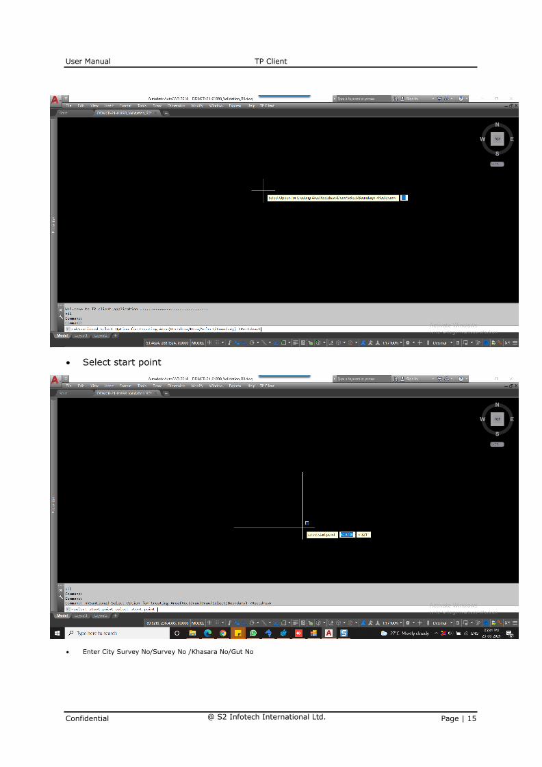
Select Option for Creating Area(RectDraw/Draw/Select/Boundary)
User Manual TP Client
Confidential @ S2 Infotech International Ltd. Page | 15
• Select start point
• Enter City Survey No/Survey No /Khasara No/Gut No

User Manual TP Client
Confidential @ S2 Infotech International Ltd. Page | 16
Click on TP Client -> Layout -> Mark Amalgamation Boundary.

User Manual TP Client
Confidential @ S2 Infotech International Ltd. Page | 17
• In Command line – Select Option for Creating Area (Rectangle/ Draw/
select/ Boundary) By selecting these options the user can trace the
drawing, Rectangle[r] is used when the plot is of rectangle shape, Draw
is used when plot is irregular, Select [s] is used when ploy-line is
present, Boundary [b] is used when ploy-line is present.

User Manual TP Client
Confidential @ S2 Infotech International Ltd. Page | 18

User Manual TP Client
Confidential @ S2 Infotech International Ltd. Page | 19
• Select Roads
• Click on TP Client -> Layout ->Generate Tables

User Manual TP Client
Confidential @ S2 Infotech International Ltd. Page | 20
Draw & Enter name to it.
3.3 Layer: Mark Plot Boundary. (TP Client-Plot Boundary)/Mark
Sub Plot Boundary (TP Client-Subplot boundary)

User Manual TP Client
Confidential @ S2 Infotech International Ltd. Page | 21
Description:
Draw a Plot poly as a closed polyline which is a parcel or piece of land enclosed by
definite boundaries. A Plot will contain all Proposed Works (buildings, wings), open
space, Internal Roads, Parking etc. The overall Plot Entity represent a Plan,
AutoDCR refers it as 'Layout Plan'. The overall Plot Entity represent a Plan, AutoDCR
refer it as "Layout Plan".
Shortcut Command: Mark plot Boundary - PB / Mark Sub Plot Boundary - SP
How to draw:
Following rules will be applied to main plot layer
Size plot area
Permissible FSI
Requirement of Amenity
Requirement of Recreational ground
• Requirement of Internal road, etc.
Precautions to be taken –
Draw a closed poly line correctly with text on same layer.
Provide Main access road overlapping with main plot.
Provide R.G, Amenity, reserve area, Road Widening, etc. inside Plot
boundary
Process –
Click on the Layout>> Mark Plot for Layout Boundary.

User Manual TP Client
Confidential @ S2 Infotech International Ltd. Page | 22
• In Command line – Select Option for Creating Area (Rectangle/ Draw/
select/ Boundary)
By selecting these options the user can trace the drawing,
Rectangle[r] is used when the plot is of rectangle shape, Draw is used
when plot is irregular, Select [s] is used when ploy-line is present,
Boundary [b] is used when ploy-line is present.
Draw & Enter name to it.
Enter the Type of Plot Detached/Semi-Detached/Row-House/LIG <Detached>

User Manual TP Client
Confidential @ S2 Infotech International Ltd. Page | 23
Enter the Plot No:
Enter the Type of Plot Evenly/Unevenly

User Manual TP Client
Confidential @ S2 Infotech International Ltd. Page | 24
Is it the Corner Plot? <Yes/No>
Specify the internal point to Get Area of Corner.

User Manual TP Client
Confidential @ S2 Infotech International Ltd. Page | 25
Now, pick the internal point.

User Manual TP Client
Confidential @ S2 Infotech International Ltd. Page | 26
3.4 Layer: Create Plot Side. (TP Client-Front-Line)/Create Sub
Plot Side (TP Client-SubFront-Line)
Description:
Draw a Plot poly as a closed polyline which is a parcel or piece of land enclosed by
definite boundaries. A Plot will contain all Proposed Works (buildings, wings), open
space, Internal Roads, Parking etc. The overall Plot Entity represent a Plan, refers
it as 'Layout Plan'. The overall Plot Entity represent a Plan, refer it as "Layout Plan".

User Manual TP Client
Confidential @ S2 Infotech International Ltd. Page | 27
How to draw:
Following rules will be applied to main plot layer
Size plot area
Permissible FSI
Requirement of Amenity
Requirement of Recreational ground
• Requirement of Internal road, etc.
Precautions to be taken –
Draw a closed poly line correctly with text on same layer.
Provide Main access road overlapping with main plot.
Provide R.G, Amenity, reserve area, Road Widening, etc. inside Plot
boundary
Process –
Click on the layer Mark Plot Boundary.
• In Command line – Select Option for Creating Area (Rectangle/ Draw/
select/ Boundary) By selecting these options the user can trace the
drawing, Rectangle [r] is used when the plot is of rectangle shape,
Draw is used when plot is irregular, Select [s] is used when ploy-line is
present, Boundary [b] is used when ploy-line is present.
• Draw it.
• Then click on Create Plot side and mark front, rear, left and right side
boundary of plot
3.5 Layer: Mark Reserve Area
Description:
Reserved area (Reservation area in Development plan) shall be drawn on this layer
if present in proposal. This can be any area reserved for/by Authority for future.
Shortcut Command: RA
How to draw:
Following rules will be applied to Reserve Area layer
Reserve area
User Manual TP Client
Confidential @ S2 Infotech International Ltd. Page | 28
• Deduction
Precautions to be taken –
Draw polyline correctly
Give name to this object in same layer as that of object
If this polyline has not been drawn and named correctly then all above
rules will not get checked
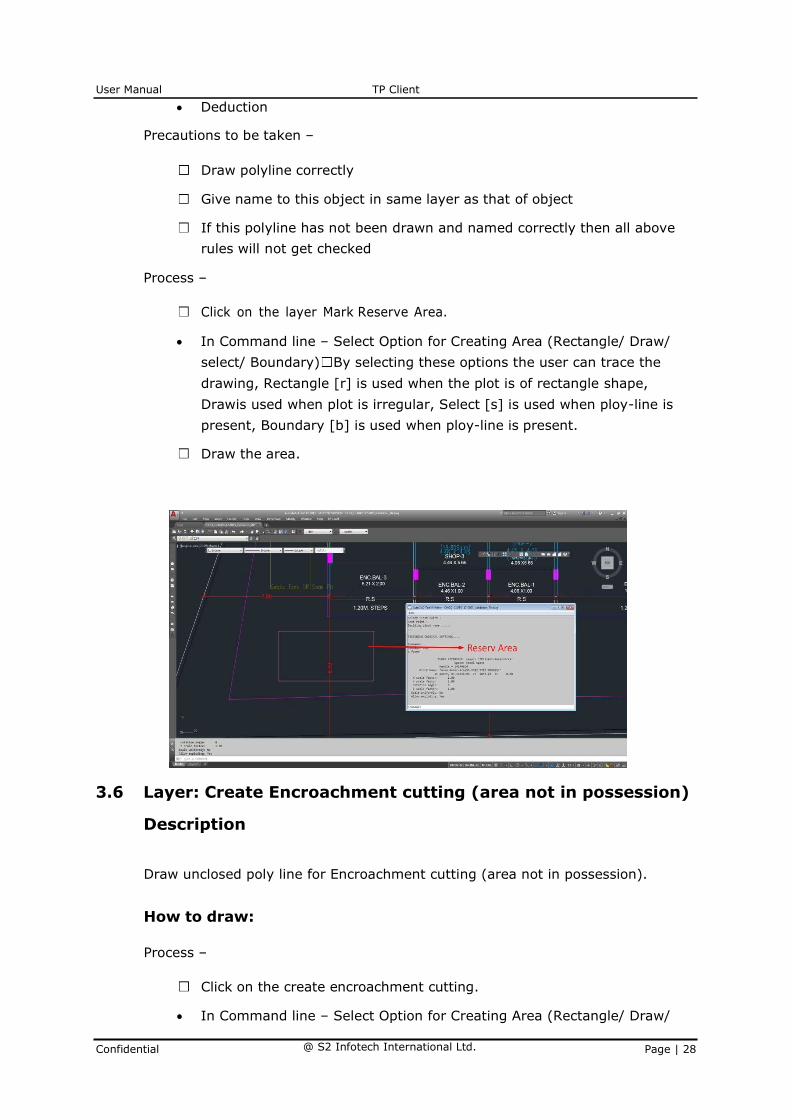
Process –
Click on the layer Mark Reserve Area.
• In Command line – Select Option for Creating Area (Rectangle/ Draw/
select/ Boundary) By selecting these options the user can trace the
drawing, Rectangle [r] is used when the plot is of rectangle shape,
Draw is used when plot is irregular, Select [s] is used when ploy-line is
present, Boundary [b] is used when ploy-line is present.
Draw the area.
3.6 Layer: Create Encroachment cutting (area not in possession)
Description
Draw unclosed poly line for Encroachment cutting (area not in possession).
How to draw:
Process –
Click on the create encroachment cutting.
• In Command line – Select Option for Creating Area (Rectangle/ Draw/

User Manual TP Client
Confidential @ S2 Infotech International Ltd. Page | 29
select/ Boundary) By selecting these options the user can trace the
drawing, Rectangle[r] is used when the plot is of rectangle shape, Draw
is used when plot is irregular, Select [s] is used when ploy-line is
present, Boundary [b] is used when ploy-line is present.
Draw unclosed line.
3.7 Layer: Mark Existing Structure Demolished
Description:
Draw a structure which already approved by authority as a closed poly. And mark
this as 'To be demolished' by using Mark option from TP Client Menu.
Shortcut Command: SD
How to draw:
Following rules will be applied on the objects of Existing Structure Demolished layer
Existing coverage area
Existing built up area
Precautions to be taken –
Draw poly line properly and give a text and Mark “To be Demolished”
Process –
Click on the layer Existing Structure Demolished.
In Command line – Select Option for Creating Area
(Rectangle/ Draw/ select/ Boundary) By selecting these
options the user can trace the drawing, Rectangle[r] is used
when the plot is of rectangle shape, Draw is used when plot
is irregular, Select [s] is used when ploy-line is present,
Boundary [b] is used when ploy-line is present.
Draw the area.

User Manual TP Client
Confidential @ S2 Infotech International Ltd. Page | 30
3.8 Layer: Mark Drainage Line
Description:
Draw unclosed poly line for drainage line
Shortcut Command: DL
How to draw:
Process –
Click on the layer Mark Drainage Line.
• In Command line – Select Option for Creating Area (Rectangle/ Draw/
select/ Boundary) By selecting these options the user can trace the
drawing, Rectangle[r] is used when the plot is of rectangle shape, Draw
is used when plot is irregular, Select [s] is used when ploy-line is
present, Boundary [b] is used when ploy-line is present.
Draw unclosed line.

User Manual TP Client
Confidential @ S2 Infotech International Ltd. Page | 31
Layer: Mark Water Line
Description:
• Draw unclosed line for water line
Shortcut Command: WL
How to draw: Process –
• Click on the layer Mark Water Line.
• In Command line – Select Option for Creating Area (Rectangle/ Draw/
select/ Boundary) By selecting these options the user can trace the drawing, Rectangle[r] is used when the plot is of rectangle shape, Draw
is used when plot is irregular, Select [s] is used when ploy-line is present, Boundary [b] is used when ploy-line is present.
• Draw unclosed line.
3.9 Layer: Mark Ramp
Description:
Draw a Ramp poly as a closed polyline in floor plans and/or plot. Naming convention
for ramp is "---m. long and ---m.
Shortcut Command: MR
How to draw:
Following rules will be applied on the objects of Ramp layer
Width
• Slope
Process –
Click on the layer Mark Ramp.

User Manual TP Client
Confidential @ S2 Infotech International Ltd. Page | 32
• Select non-vehicular or vehicular.
• Enter start level height in …m‟ & width in …m‟.
• Specify 1st point specify last point – Note should be marked from
center to center of ramp & enter.
3.10 Layer: Mark Nallah
Description:
Draw Nallah as closed polyline as Nallah
How to draw
Following rules will be applied on the objects of recreational ground layer
• A distance of 6 m. from the edge of minor water course (nallah) is to be left as
marginal distance for construction of any building
• Swimming pools, club houses, recreational facilities after leaving 15 m. belt along
river bank and 9m. from nallahs
Process –
Click on the layer Mark Nala
• In Command line – Select Option for Creating Area (Rectangle/ Draw/
select/ Boundary) By selecting these options the user can trace the
drawing, Rectangle[r] is used when the plot is of rectangle shape, Draw
is used when plot is irregular, Select [s] is used when ploy-line is
present, Boundary [b] is used when ploy-line is present.
Draw closed line.

User Manual TP Client
Confidential @ S2 Infotech International Ltd. Page | 33
3.11 Layer: Mark Flood line
Description:
Area between blue flood line and red flood line shall be restrictive zone for the purposes of
construction.
How to draw:
Precautions to be taken –
Draw polyline correctly
Process –
Click on the layer Mark flood line
• Then chose which flood line you want to mark (RED/BLUE)
• In Command line – Select Option for Creating Area (Rectangle/ Draw/
select/ Boundary) By selecting these options the user can trace the
drawing, Rectangle[r] is used when the plot is of rectangle shape, Draw
is used when plot is irregular, Select [s] is used when ploy-line is
present, Boundary [b] is used when ploy-line is present.
3.12 Layer: Mark Open Space/ Recreational G Open Space
Description:
Draw Recreational Ground as closed polyline reserved as open space/ recreational
space on this layer.
How to draw:
Following rules will be applied on the objects of recreational ground layer
Balance plot
Deduction in area calculation
Minimum recreation ground area/ open space
• Plot area in side recreation ground
Precautions to be taken –
Draw polyline correctly
If this polyline has not been drawn correctly then all above rules will not

User Manual TP Client
Confidential @ S2 Infotech International Ltd. Page | 34
get checked
Process –
Click on the layer Mark Open Space/ Recreational Ground
• In Command line – Select Option for Creating Area (Rectangle/ Draw/
select/ Boundary) By selecting these options the user can trace the
drawing, Rectangle[r] is used when the plot is of rectangle shape, Draw
is used when plot is irregular, Select [s] is used when ploy-line is
present, Boundary [b] is used when ploy-line is present.
Draw closed line.
User Manual TP Client
Confidential @ S2 Infotech International Ltd. Page | 35
3.13 Layer: Mark Amenity Area
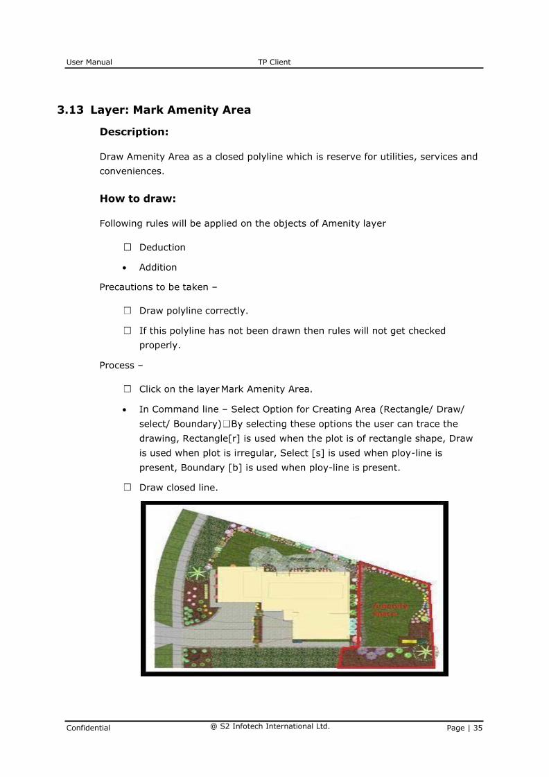
Description:
Draw Amenity Area as a closed polyline which is reserve for utilities, services and
conveniences.
How to draw:
Following rules will be applied on the objects of Amenity layer
Deduction
• Addition
Precautions to be taken –
Draw polyline correctly.
If this polyline has not been drawn then rules will not get checked
properly.
Process –
Click on the layer Mark Amenity Area.
• In Command line – Select Option for Creating Area (Rectangle/ Draw/
select/ Boundary) By selecting these options the user can trace the
drawing, Rectangle[r] is used when the plot is of rectangle shape, Draw
is used when plot is irregular, Select [s] is used when ploy-line is
present, Boundary [b] is used when ploy-line is present.
Draw closed line.
User Manual TP Client
Confidential @ S2 Infotech International Ltd. Page | 36
3.14 Layer: Mark Existing Building in Plot
Description:
If you are getting permission for layout and containing existing building in it, then
you need draw building periphery of that building.
How to draw:
Process –
Click on the layer Mark Existing Building in Plot
• In Command line – Select Option for Creating Area
(Rectangle/ Draw/ select/ Boundary) By selecting these
options the user can trace the drawing, Rectangle[r] is used
when the plot is of rectangle shape, Draw is used when plot
is irregular, Select [s] is used when ploy-line is present,
Boundary [b] is used when ploy-line is present.
• Draw closed line & name it.
3.15 Layer: Mark Building in Plot
Description:
If you are getting permission for layout and containing building in it, then you need
draw building periphery of that building. In this case, tentative block of building will
refer just the presence of building in Plot.
How to draw:
Process –
Click on the layer Mark Building in Plot
• In Command line – Select Option for Creating Area
(Rectangle/ Draw/ select/ Boundary) By selecting these
options the user can trace the drawing, Rectangle[r] is used
when the plot is of rectangle shape, Draw is used when plot
is irregular, Select [s] is used when ploy-line is present,
Boundary [b] is used when ploy-line is present.
• Draw closed line & name it.

User Manual TP Client
Confidential @ S2 Infotech International Ltd. Page | 37
3.16 Layer: Mark Basement Parking Area.
How to draw:
Process –
Click on the layer Mark Basement Parking Area
• In Command line – Select Option for Creating Area
(Rectangle/ Draw/ select/ Boundary) By selecting these
options the user can trace the drawing, Rectangle[r] is used
when the plot is of rectangle shape, Draw is used when plot
is irregular, Select [s] is used when ploy-line is present,
Boundary [b] is used when ploy-line is present.
Draw closed line.
3.17 Layer: Mark Podium Parking Area.
How to draw:
Process –
Click on the layer Mark Podium Parking Area
• In Command line – Select Option for Creating Area
(Rectangle/ Draw/ select/ Boundary) By selecting these
options the user can trace the drawing, Rectangle[r] is used
when the plot is of rectangle shape, Draw is used when plot
is irregular, Select [s] is used when ploy-line is present,
Boundary [b] is used when ploy-line is present.
Draw closed line.

User Manual TP Client
Confidential @ S2 Infotech International Ltd. Page | 38
3.18 Layer: Mark Open Parking Area.
How to draw:
Process –
Click on the layer Mark Open Parking Area
• In Command line – Select Option for Creating Area
(Rectangle/ Draw/ select/ Boundary) By selecting these
options the user can trace the drawing, Rectangle[r] is used
when the plot is of rectangle shape, Draw is used when plot
is irregular, Select [s] is used when ploy-line is present,
Boundary [b] is used when ploy-line is present.
Draw closed line.
3.19 Layer: Mark Column
Description:
Draw each column as closed poly line on “Column” layer inside parking floor as well
as inside and overlapped with Building line layer in other floors.
How to draw:
Process –
Click on the layer Mark Column
• In Command line – Select Option for Creating Area (Rectangle/ Draw/
select/ Boundary) By selecting these options the user can trace the
drawing, Rectangle[r] is used when the plot is of rectangle shape, Draw
is used when plot is irregular, Select [s] is used when ploy-line is
present, Boundary [b] is used when ploy-line is present.
Draw closed line.

User Manual TP Client
Confidential @ S2 Infotech International Ltd. Page | 39
3.20 Layer: Mark Compound Wall.
Description:
Draw poly line of compound wall to be drawn on proposed compound wall with text
started with compound wall height. E.g. 1.5m. High Compound Wall
How to draw:
Following rules will be applied to Compound Wall
Height
Precautions to be taken –
Draw a closed poly line correctly.
Process –
Click on the layer Mark Compound Wall.
In Command line – Select Option 1.Front/2.Rear/3.Side
Enter wall width in ‘m’

User Manual TP Client
Confidential @ S2 Infotech International Ltd. Page | 40
Specify 1st & last point.
Enter Height in ‘m’.
3.21 Layer: Mark Exit/ Entrance Gate
Description:
Draw closed poly line for Mark Exit/Entrance Gate.
Shortcut Command: EG
How to draw:
Process –
Click on the layer Mark Exit/Entrance Gate.
• In Command line – Select Option for Creating Area (Rectangle/ Draw/
select/ Boundary) By selecting these options the user can trace the
drawing, Rectangle[r] is used when the plot is of rectangle shape, Draw
is used when plot is irregular, Select [s] is used when ploy-line is
present, Boundary [b] is used when ploy-line is present.
Enter height in meter e.g.: 2.1m.
3.22 Layer: Mark Substructure.
Description:
Draw closed ploy line for Mark Substructure.

User Manual TP Client
Confidential @ S2 Infotech International Ltd. Page | 41
How to draw:
Process –
Click on the layer Mark Substructure.
In command drop down all options will get display such as 1. Electrical
Room/2. Transformer Room etc. by selecting 1,2,3,4 etc. you can select
the point which you want to mark.
• In Command line – Select Option for Creating Area (Rectangle/ Draw/
select/ Boundary) By selecting these options the user can trace the
drawing, Rectangle[r] is used when the plot is of rectangle shape, Draw
is used when plot is irregular, Select [s] is used when ploy-line is
present, Boundary [b] is used when ploy-line is present.
3.23 Layer: Mark STP
Description:
Draw unclosed polyline for STP
How to draw:
Process –
Click on the layer Mark STP.
• In Command line – Select Option for Creating Area (Rectangle/ Draw/
select/ Boundary) By selecting these options the user can trace the
drawing, Rectangle[r] is used when the plot is of rectangle shape, Draw
is used when plot is irregular, Select [s] is used when ploy-line is present,
Boundary [b] is used when ploy-line is present.
Draw unclosed line.

User Manual TP Client
Confidential @ S2 Infotech International Ltd. Page | 42
3.24 Layer: Mark OWC
Description:
Draw unclosed polyline for OWC
How to draw:
Process –
Click on the layer Mark OWC.
• In Command line – Select Option for Creating Area (Rectangle/ Draw/
select/ Boundary) By selecting these options the user can trace the
drawing, Rectangle[r] is used when the plot is of rectangle shape, Draw
is used when plot is irregular, Select [s] is used when ploy-line is present,
Boundary [b] is used when ploy-line is present.
Draw unclosed line.
3.25 Layer: Mark Recreational structure
Description:
Draw unclosed polyline for recreational structure
How to draw:
Process –
Click on the layer Mark recreational structure.
• Chose 1st floor or 2nd floor.
• Select whichever recreational structure you need from options
• In Command line – Select Option for Creating Area (Rectangle/ Draw/
select/ Boundary) By selecting these options the user can trace the
drawing, Rectangle[r] is used when the plot is of rectangle shape, Draw
is used when plot is irregular, Select [s] is used when ploy-line is present,
Boundary [b] is used when ploy-line is present.
Draw unclosed line.
3.26 Layer: Mark Electrical lines
Description:
Draw polyline for Electrical line
How to draw:
Process –
Click on the layer Mark Electrical line

User Manual TP Client
Confidential @ S2 Infotech International Ltd. Page | 43
• Chose 1st Low, 2nd High, 3rd Extra high.
• Give elevation height.
Draw poly line.
3.27 Layer: Place Tree /Place Fire Alarm
Description:
Pick the point where you want to place it.
3.28 Layer: Mark Helipad
Description:
Draw closed ploy line where you want to mark the Helipad it is allowed only in High
rise structure.
How to draw:
Process –
Click on the layer Mark Helipad.
• In Command line – Select Option for Creating Area (Rectangle/ Draw/
select/ Boundary) By selecting these options the user can trace the
drawing, Rectangle[r] is used when the plot is of rectangle shape, Draw
is used when plot is irregular, Select [s] is used when ploy-line is
present, Boundary [b] is used when ploy-line is present.
Draw closed ploy line.
3.29 Layer: Mark Major water course
Description:
Draw closed ploy line where you want to mark the major water course
How to draw:
Process –
Click on the layer Mark major water course.
• In Command line – Select Option for Creating Area (Rectangle/ Draw/
select/ Boundary) By selecting these options the user can trace the
drawing, Rectangle[r] is used when the plot is of rectangle shape, Draw
is used when plot is irregular, Select [s] is used when ploy-line is
present, Boundary [b] is used when ploy-line is present.
Draw closed ploy line.
3.30 Layer: Mark Minor water course
User Manual TP Client
Confidential @ S2 Infotech International Ltd. Page | 44
Description:
Draw closed ploy line where you want to mark the minor water course
How to draw:
Process –
Click on the layer Mark minor water course.
• In Command line – Select Option for Creating Area (Rectangle/ Draw/
select/ Boundary) By selecting these options the user can trace the
drawing, Rectangle[r] is used when the plot is of rectangle shape, Draw
is used when plot is irregular, Select [s] is used when ploy-line is
present, Boundary [b] is used when ploy-line is present.
Draw closed ploy line.
3.31 Layer: Mark Cycle track
Description:
Draw unclosed polyline for Cycle track
How to draw:
Process –
Click on the layer Mark Cycle track.
• In Command line – Select Option for Creating Area (Rectangle/ Draw/
select/ Boundary) By selecting these options the user can trace the
drawing, Rectangle[r] is used when the plot is of rectangle shape, Draw
is used when plot is irregular, Select [s] is used when ploy-line is present,
Boundary [b] is used when ploy-line is present.
Draw unclosed polygon.
3.32 ROAD - Layer: Mark Access Road
Description:
Draw road with text specifying its width and draw a center line of road.
How to draw:
Process –
Following rules will be applied
Width
• Length

User Manual TP Client
Confidential @ S2 Infotech International Ltd. Page | 45
Precautions to be taken –
Draw a unclosed poly line correctly and give text of width of road on
command line eg: - 9 m.
Draw main Road in front of Front Margin, marking main road is import to
get proper permissible building height.
3.33 ROAD - Layer: Mark Main Road
Description:
Draw road with text specifying its width and draw a center line of road.
Shortcut Command: MMR
How to draw:
Process –
Following rules will be applied
Width
• Length
Precautions to be taken –
Draw a unclosed poly line correctly and give text of width of road on
command line eg: - 9 m.
Draw main Road in front of Front Margin, marking main road is import to
get proper permissible building height.
User Manual TP Client
Confidential @ S2 Infotech International Ltd. Page | 46
3.34 Layer: Mark Road Widening
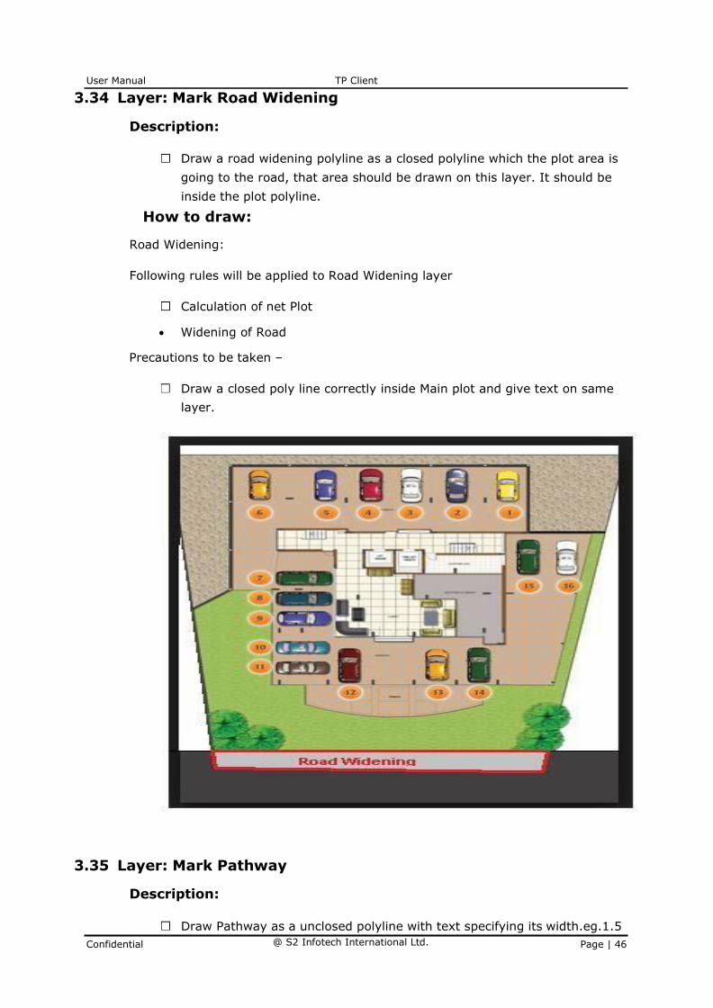
Description:
Draw a road widening polyline as a closed polyline which the plot area is
going to the road, that area should be drawn on this layer. It should be
inside the plot polyline.
How to draw:
Road Widening:
Following rules will be applied to Road Widening layer
Calculation of net Plot
• Widening of Road
Precautions to be taken –
Draw a closed poly line correctly inside Main plot and give text on same
layer.
3.35 Layer: Mark Pathway
Description:
Draw Pathway as a unclosed polyline with text specifying its width.eg.1.5

User Manual TP Client
Confidential @ S2 Infotech International Ltd. Page | 47
m. wide pathway.
How to draw:
Pathway:
Following rules will be applied on the objects of Pathway layer
Length
• Width
Precautions to be taken –
Draw polyline correctly
Give width to this object in same layer as that of object
If this polyline has not been drawn and named correctly then all above
rules will not get checked
3.36 BUILDING - Layer: Mark Building Boundary.
Description:
Draw rectangle around by considering all the Floor plans, Section &
elevation, site plan etc. so that while generating the floors get identified,
eg Ground floors details get identified.
How to draw:
Draw rectangle around the considering whole drawing so that it get
identified while generating.

User Manual TP Client
Confidential @ S2 Infotech International Ltd. Page | 48
3.37 Layer: Mark Dead wall.
Description:
Draw line around building in plot to show dead wall and mark it
How to draw:
Draw line around building.
3.38 Layer: Mark Floor Boundary.
Description:
Draw rectangle around single floor as shown in below eg. Draw rectangle
considering all components of ground floor then mark it.
How to draw:
Draw rectangle around each floor considering all the items of that floor,
for each floor differently.
After making it will ask to select building then select the outer building
boundary.
Then select from drop down which floor it is eg: Ground Floor, First Floor
etc.

User Manual TP Client
Confidential @ S2 Infotech International Ltd. Page | 49
3.39 Layer: Mark Reference
Description:
Put reference point on staircase corner on every floor it should be on
same point as of floor you have marked. It help in creating building
boundary
How to draw: • Click on TP Client -> Building ->Mark Reference

User Manual TP Client
Confidential @ S2 Infotech International Ltd. Page | 50
Pick the point on each floor which you want to refer.
Careful while selecting same corner should get selected on each floor
then only building boundary will be created.
User Manual TP Client
Confidential @ S2 Infotech International Ltd. Page | 51
3.40 Layer: Mark Solar
Description:
A closed polyline to represents Solar. Solar can be drawn in TERRACE
FLOOR. It should be drawn as per internal size or dimensions.
How to draw:
Draw on the floor where it is located by giving its proper capacity in
liters.

User Manual TP Client
Confidential @ S2 Infotech International Ltd. Page | 52
3.41 Layer: Mark Rain Water Harvesting Tank
Description:
A Diagram layer represents a rain water harvesting.
How to draw:
Just pick one point, there diagram will come of rain water harvesting
3.42 Layer: Grey water management.
Description:
Pick the point where you want to place the grey water management
How to draw:
Process –
Click on the layer Mark Grey water management.
• In Command line – Select Option for Creating Area (Rectangle/ Draw/
select/ Boundary) By selecting these options the user can trace the
drawing, Rectangle[r] is used when the plot is of rectangle shape, Draw
is used when plot is irregular, Select [s] is used when ploy-line is present,
Boundary [b] is used when ploy-line is present.
Draw unclosed line.
3.43 Layer: OHT.
Description:
Pick normal or fire OHT
How to draw:
Process –
Click on the layer OHT
• Chose normal or fire OHT
• In Command line – Select Option for Creating Area (Rectangle/ Draw/
select/ Boundary) By selecting these options the user can trace the
drawing, Rectangle[r] is used when the plot is of rectangle shape, Draw
is used when plot is irregular, Select [s] is used when ploy-line is present,
Boundary [b] is used when ploy-line is present.
• Mention height and capacity

User Manual TP Client
Confidential @ S2 Infotech International Ltd. Page | 53
3.44 Layer: UGR.
Description:
Pick normal or fire UGR
How to draw:
Process –
Click on the layer UGR
• Chose normal or fire UGR
• In Command line – Select Option for Creating Area (Rectangle/ Draw/
select/ Boundary) By selecting these options the user can trace the
drawing, Rectangle[r] is used when the plot is of rectangle shape, Draw
is used when plot is irregular, Select [s] is used when ploy-line is present,
Boundary [b] is used when ploy-line is present.
• Mention height and capacity
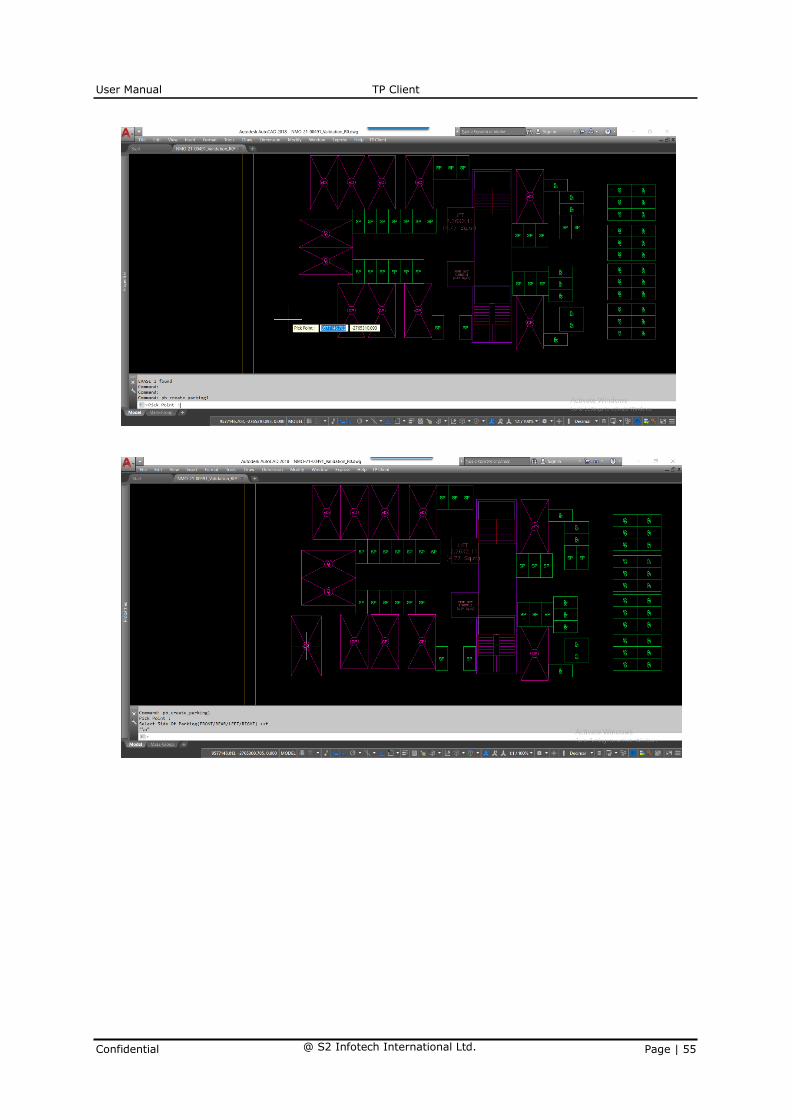
3.45 Layer: Parking with structural details.
Description:
Pick the point where you want to place the vehicles select the vehicle
type from command line, once you select the type e.g.: Car, then auto
rectangle of standard size of car gets created.
How to draw:
Process:
Go to TP Client. Click on Building -> Parking with Structural Details.

User Manual TP Client
Confidential @ S2 Infotech International Ltd. Page | 54
Mention height and capacity
Parking:
Following rules will be applied to Parking layer
Select the type of Vehicles & pick the point where you want to mark.
• Chose the Parking Type
• Select the Parking Size.
User Manual TP Client
Confidential @ S2 Infotech International Ltd. Page | 55

User Manual TP Client
Confidential @ S2 Infotech International Ltd. Page | 56
Precautions to be taken –
• If it is not inserted correctly then no of proposed parking‟s will not come
proper.

User Manual TP Client
Confidential @ S2 Infotech International Ltd. Page | 57
3.46 Layer: Composite parking.
Description:
Pick the point where you want to place the vehicles select the vehicle
type from command line,
How to draw:
How to draw:
Process:
Go to TP Client. Click on Building -> Mark Composite Parking.
Composite Parking:
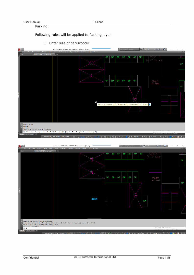
• Select your option 1 car and 2 scooter, 1 small car and 2 scooter,
6 scooter or 1 car
• Chose vertical alignment or horizontal alignment
User Manual TP Client
Confidential @ S2 Infotech International Ltd. Page | 58
Parking:
Following rules will be applied to Parking layer
Enter size of car/scooter

User Manual TP Client
Confidential @ S2 Infotech International Ltd. Page | 59
3.47 Layer: Mechanical parking.
Description:
Pick the Stack parking or Puzzle, pit or Tower parking
How to draw:
• For stack parking use 1. Two stack, 2. Three stack, 3. Four stack.
• For puzzle parking use In Command line – Select Option for
Creating Area (Rectangle/ Draw/ select/ Boundary) By selecting
these options the user can trace the drawing, Rectangle[r] is
used when the plot is of rectangle shape, Draw is used when plot
is irregular, Select [s] is used when ploy-line is present, Boundary
[b] is used when ploy-line is present.
• For pit parking use use In Command line – Select Option for
Creating Area (Rectangle/ Draw/ select/ Boundary) By selecting
these options the user can trace the drawing, Rectangle[r] is used
when the plot is of rectangle shape, Draw is used when plot is
irregular, Select [s] is used when ploy-line is present, Boundary [b]
is used when ploy-line is present
• For Tower parking use 1. Vertical or 2. Rotary parking option.
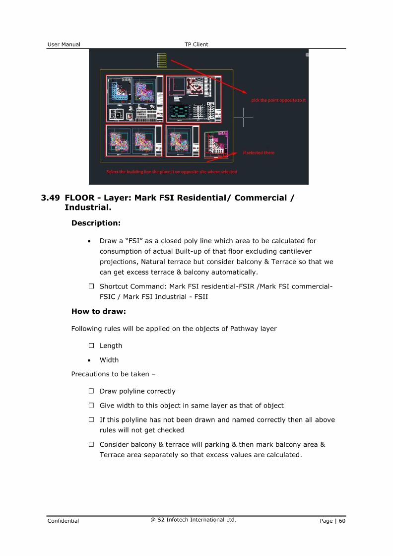
3.48 Layer: Draw Section View
Description:
Select the building line (Yellow Rectangle) which you have already
created then pick the opposite point so that section (line Section) to
define height is created atomically.
How to draw:
Section:
Following rules will be applied on the objects of Section layer
All Floors in section
Ground level
• Building height
Precautions to be taken –
Follow the same process as given above for drawing line section view so
that it gives proper result.
User Manual TP Client
Confidential @ S2 Infotech International Ltd. Page | 60
3.49 FLOOR - Layer: Mark FSI Residential/ Commercial / Industrial.
Description:
• Draw a “FSI” as a closed poly line which area to be calculated for
consumption of actual Built-up of that floor excluding cantilever
projections, Natural terrace but consider balcony & Terrace so that we
can get excess terrace & balcony automatically.
Shortcut Command: Mark FSI residential-FSIR /Mark FSI commercial-
FSIC / Mark FSI Industrial - FSII
How to draw:
Following rules will be applied on the objects of Pathway layer
Length
• Width
Precautions to be taken –
Draw polyline correctly
Give width to this object in same layer as that of object
If this polyline has not been drawn and named correctly then all above
rules will not get checked
Consider balcony & terrace will parking & then mark balcony area &
Terrace area separately so that excess values are calculated.

User Manual TP Client
Confidential @ S2 Infotech International Ltd. Page | 61
3.50 Layer: Mark Carpet Area
Description:
Draw carpet area as a closed poly line which is a net usable floor area
within a building excluding that covered by the walls or any other areas
specifically exempted from floor space index computation in this
regulation.
How to draw:
Carpet Area:
Following rules will be applied to carpet area layer
Per Carpet Tenement number check required
Tenement density
Water tank calculation
Precautions to be taken –

User Manual TP Client
Confidential @ S2 Infotech International Ltd. Page | 62
Draw poly line correctly Give text of carpet area as Floor name or flat
number etc. while creating layer to identify your carpet
If this poly line has not been drawn and named correctly then all above
rules will not get checked.
3.51 Layer: Mark Room
Description:
Draw closed polyline of Room layer represents a rooms ie. Bedroom,
Master Bedroom, other room etc. In command the rooms will display
user can select the option which room he want to select by clicking 1,
2,3etc. Then give proper text to the room by tying in command field.
How to draw:
Following rules will be applied on the objects of room layer
• Click on TP Client menu Floor Mark Room
Once you select mark room in command line types of room get display
e.g.: 1. habitable room, 2. other room 3. Store room, 4. Shop etc.
select 1 or 2 which ever room you need to mark.
Then type the text you require & auto dimension (Room size, Width) will
get display with that text.

User Manual TP Client
Confidential @ S2 Infotech International Ltd. Page | 63
Precautions to be taken –
Draw closed poly line properly and give name to this object.
Room must be inside carpet area poly line.
3.52 Layer: Mark Kitchen / Mark Toilet / Mark WC / Mark Bathroom / Mark Toilets for differently abled /mark Urinals
Description:
Draw closed polyline of Kitchen. Then give proper text to the room by
tying in command field.
How to draw:
Following rules will be applied on the objects of room layer
• Click on TP Client menu Floor Mark Kitchen
Select mark Kitchen Draw closed poly line or select poly line to mark it.
Then type the text you require & auto dimension (Room size, Width) will
get display with that text.
Precautions to be taken –
Draw closed poly line properly and give name to this object.

User Manual TP Client
Confidential @ S2 Infotech International Ltd. Page | 64
Kitchen room must be inside carpet area poly line.
For Mark Toilet/ Mark WC / Mark Bathroom for all these same option as
we used for kitchen should be used.
3.53 Layer: Mark Ledge or tand/loft
Description:
Draw closed polyline. Then give height of loft
How to draw:
• Click on TP Client menu Floor Mark Ledge or loft
Draw closed polygon, then proper text as loft will come.
3.54 Layer: Mark Balcony
Description:
Draw closed poly line of Balcony. Select which type of balcony it is
normal or enclosed. Then give proper text to the balcony by tying in

User Manual TP Client
Confidential @ S2 Infotech International Ltd. Page | 65
command field.
How to draw:
Following rules will be applied on the objects
• Click on TP Client menu Floor Mark Balcony
Type 1: Normal
Select mark Balcony Draw closed poly line or select poly line to mark it.
• Select Option (1.Normal/2.Enclosed)

User Manual TP Client
Confidential @ S2 Infotech International Ltd. Page | 66
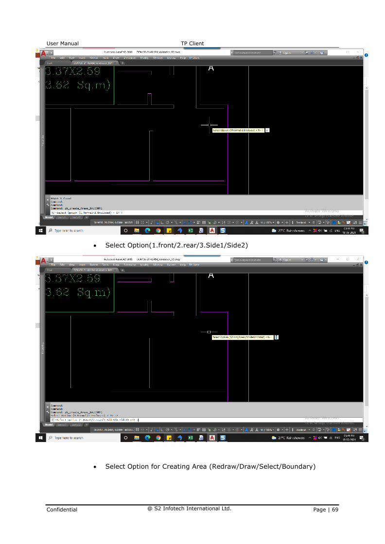
• Select Option(1.front/2.rear/3.Side1/Side2)
• Select Option for Creating Area (Redraw/Draw/Select/Boundary)

User Manual TP Client
Confidential @ S2 Infotech International Ltd. Page | 67
• Choose the End Points.

User Manual TP Client
Confidential @ S2 Infotech International Ltd. Page | 68
Type 2: Enclosed Balcony
Select mark Balcony Draw closed poly line or select poly line to mark it.
• Select Option (1.Normal/2.Enclosed)
User Manual TP Client
Confidential @ S2 Infotech International Ltd. Page | 69
• Select Option(1.front/2.rear/3.Side1/Side2)
• Select Option for Creating Area (Redraw/Draw/Select/Boundary)

User Manual TP Client
Confidential @ S2 Infotech International Ltd. Page | 70
• Select the end points.

User Manual TP Client
Confidential @ S2 Infotech International Ltd. Page | 71
• Then type the text you require & auto dimension of Balcony will
get display with that text.

User Manual TP Client
Confidential @ S2 Infotech International Ltd. Page | 72
Precautions to be taken –
Draw closed poly line properly and give name to this object.
Consider balcony in FSI line so that we can identify & calculate %
permissible & excess proposed to that floor.

User Manual TP Client
Confidential @ S2 Infotech International Ltd. Page | 73
3.55 Layer: Mark Terrace
Description:
Draw closed poly line of Terrace.
How to draw:
Following rules will be applied on the objects
• Click on TP Client menu Floor Mark Terrace
• Select mark Terrace Draw closed poly line or select poly line to mark it.
Precautions to be taken –
Draw closed poly line properly and give name to this object.
Consider Terrace in FSI line so that we can identify & calculate %
permissible & excess proposed to that floor.
3.56 Layer: Mark Head Room
Description:
Draw closed poly of Headroom on Terrace as headroom are placed on
terrace above staircase.
How to draw:
Following rules will be applied on the objects
• Click on TP Client menu Floor Mark Head Room.
Select mark Head Room Draw closed poly line or select poly line to mark
it.
Precautions to be taken –
Draw closed poly line properly and give height of headroom.
3.57 Layer: Mark Mezzanine
Description:
Draw closed poly of Mezzanine floor were in room it is placed.
How to draw:
Following rules will be applied on the objects
• Click on TP Client menu Floor Mark Mezzanine.
Select mark Mezzanine draw closed poly line or select poly line to mark

User Manual TP Client
Confidential @ S2 Infotech International Ltd. Page | 74
it in which room you want to place.
Precautions to be taken –
Draw closed poly line properly and give height of Mezzanine.
3.58 Layer: Create Door/ Ventilation /Window
Description:
• Door/ Ventilation /Window is a closed Polyline which is drawn on location
of window. Enter proper height when asked in command & give naming
convention as “V,W1,D1” etc
How to draw:
Following rules will be applied on the objects
• Click on TP Client menu Floor create Door/ Ventilation /Window
Select create Door/ Ventilation /Window draw closed poly line or select
poly line to mark it in which room you want to place.
Precautions to be taken –
Draw closed poly line properly and give height of Door/ Ventilation
/Window.
3.59 Layer: Mark Passage/Corridors/Lobby

User Manual TP Client
Confidential @ S2 Infotech International Ltd. Page | 75
Description:
Draw a closed polyline of passage/corridors/Lobby. It is a common
passage or circulation space including a common entrance hall. Select
which type of passage it is by selecting from command. Lift lobbies to be
drawn on same layer and to be marked it as Paid by using from
command.
Shortcut Command: MP
How to draw:
Following rules will be applied on the objects
• Click on TP Client menu Floor Mark passage/corridors/Lobby
• Select Mark passage/corridors/Lobby, select option from command
1.open passage or corridors/2.covered free from Fsi/3.covered Taken in
F.s.i/4.Lobby you can select any of the option by clicking 1,2,3,4 then
option Rectangle/Draw/Select/Boundary will display in
Command line you can select “S” & select the poly line the it will
mark automatically for Draw-D, for rectangle-r, Boundary-b can select
& mark it.
Precautions to be taken –
Draw closed poly line properly.
3.60 Layer: Mark Escalators
Description:
Draw closed poly line of mark escalators this is usefully in case of malls,
huge complexes etc.
How to draw:
Following rules will be applied on the objects

User Manual TP Client
Confidential @ S2 Infotech International Ltd. Page | 76
• Click on TP Client menu Floor Mark Escalators
• Option Rectangle/Draw/Select/Boundary will display in command line you
can select “S” & select the poly line then it will mark automatically for
Draw-D, for rectangle-r, Boundary-b can select & mark it.
Precautions to be taken –
Draw closed poly line properly.
You can mark rectangle around the escalator in plan.
3.61 Layer: Mark Lift
Description:
Draw closed poly line of Mark Lift.
Shortcut Command: LIF
How to draw:
Following rules will be applied on the objects
• Click on TP Client menu Floor Mark Lift
Select Mark Lift, select option from command 1.Lift/2.Machine Lift/3.Fire
Lift you can select any of the option by clicking 1, 2,3.
Then option 1.Remove From Fsi /2.Taken in Fsi will display you can
select any of the option by clicking 1,2.
• Then Option Rectangle/Draw/Select/Boundary will display in command
line you can select “S” & select the poly line then it will mark

User Manual TP Client
Confidential @ S2 Infotech International Ltd. Page | 77
automatically for Draw-D, for rectangle-r, Boundary-b can select & mark
it.
• Then after typing text auto dimension will display.
Precautions to be taken –
Draw closed poly line properly.
3.62 Layer: Mark Lift well / Duct/ Mark Void / Mark Ventilation Shaft
Description:
Draw closed poly line of Mark Lift well/Duct/Mark Void/Mark ventilation Shaft.
How to draw:
Following rules will be applied on the objects
• Click on TP Client menu Floor Mark Duct/ Mark Void / Mark
Ventilation Shaft.
• Then Option Rectangle/Draw/Select/Boundary will display in command
line you can select “S” & select the poly line then it will mark
automatically for Draw-D, for rectangle-r, Boundary-b can select & mark
it.
Then after typing text auto dimension will display.
Precautions to be taken –
Draw closed poly line properly.

User Manual TP Client
Confidential @ S2 Infotech International Ltd. Page | 78
3.63 Layer: Mark Arch. Projection
Description:
Draw closed poly line of Mark Arch. projection.
How to draw:
Following rules will be applied on the objects
• Click on TP Client menu Floor Mark Arch. Projection.

User Manual TP Client
Confidential @ S2 Infotech International Ltd. Page | 79
• Select Mark Lift, select option from command
1. F.Bed/2.Chajja/3.C.B/4.loft/5.Canopy/6.Porch you can select any
of the option by clicking 1, 2, 3,4,5,6.
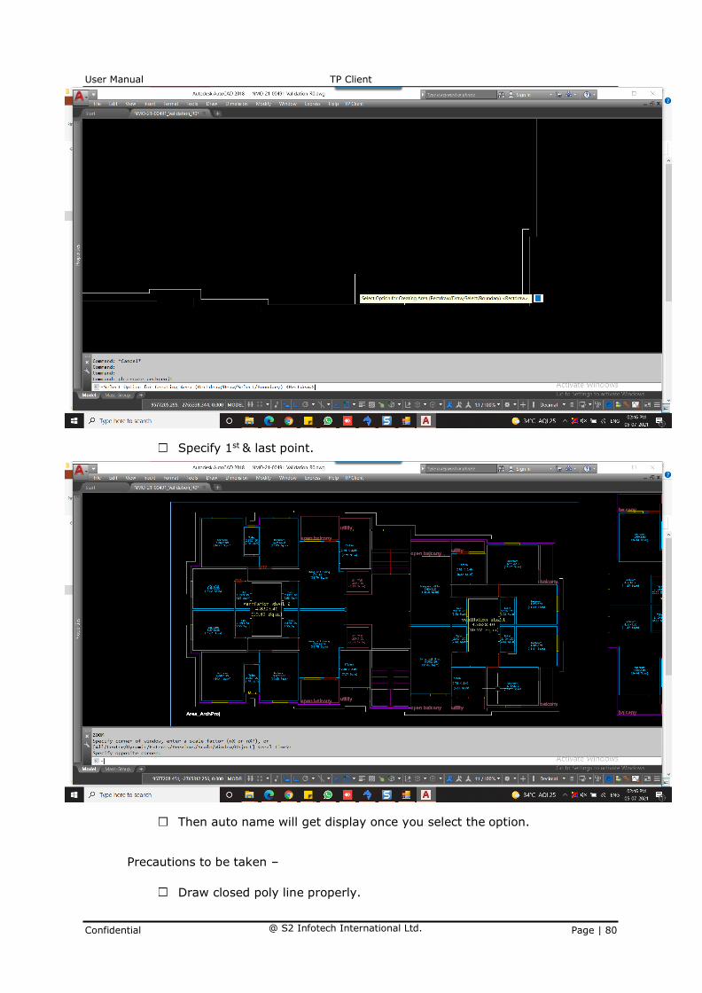
• Then Option Rectangle/Draw/Select/Boundary will display in command
line you can select “S” & select the poly line then it will mark
automatically for Draw-D, for rectangle-r, Boundary-b can select & mark
it.
User Manual TP Client
Confidential @ S2 Infotech International Ltd. Page | 80
Specify 1st & last point.
Then auto name will get display once you select the option.
Precautions to be taken –
Draw closed poly line properly.
User Manual TP Client
Confidential @ S2 Infotech International Ltd. Page | 81
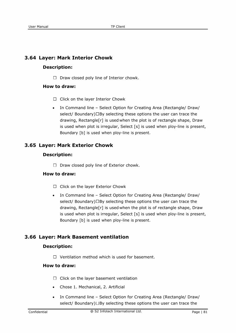
3.64 Layer: Mark Interior Chowk
Description:
Draw closed poly line of Interior chowk.
How to draw:
Click on the layer Interior Chowk
• In Command line – Select Option for Creating Area (Rectangle/ Draw/
select/ Boundary) By selecting these options the user can trace the
drawing, Rectangle[r] is used when the plot is of rectangle shape, Draw
is used when plot is irregular, Select [s] is used when ploy-line is present,
Boundary [b] is used when ploy-line is present.
3.65 Layer: Mark Exterior Chowk
Description:
Draw closed poly line of Exterior chowk.
How to draw:
Click on the layer Exterior Chowk
• In Command line – Select Option for Creating Area (Rectangle/ Draw/
select/ Boundary) By selecting these options the user can trace the
drawing, Rectangle[r] is used when the plot is of rectangle shape, Draw
is used when plot is irregular, Select [s] is used when ploy-line is present,
Boundary [b] is used when ploy-line is present.
3.66 Layer: Mark Basement ventilation
Description:
Ventilation method which is used for basement.
How to draw:
Click on the layer basement ventilation
• Chose 1. Mechanical, 2. Artificial
• In Command line – Select Option for Creating Area (Rectangle/ Draw/
select/ Boundary) By selecting these options the user can trace the

User Manual TP Client
Confidential @ S2 Infotech International Ltd. Page | 82
drawing, Rectangle[r] is used when the plot is of rectangle shape, Draw
is used when plot is irregular, Select [s] is used when ploy-line is present,
Boundary [b] is used when ploy-line is present.
3.67 Layer: Mark Stair Case.
Description:
Draw closed poly line of Mark Staircase, Mark Rectangle around the plan
of staircase.
How to draw:
Following rules will be applied on the objects
• Click on TP Client menu Floor Mark staircase.
Select Mark Staircase, select option from command 1.Normal Staircase
/2.Spiral /3.Fire Escape Stair you can select any of the option by clicking
1, 2, 3.

User Manual TP Client
Confidential @ S2 Infotech International Ltd. Page | 83
• Then Option Rectangle/Draw/Select/Boundary will display in command
line you can select “S” & select the poly line then it will mark
automatically for Draw-D, for rectangle-r, Boundary-b can select & mark
it.
• Specify 1st & last point.

User Manual TP Client
Confidential @ S2 Infotech International Ltd. Page | 84
Precautions to be taken –
Draw closed poly line properly.

User Manual TP Client
Confidential @ S2 Infotech International Ltd. Page | 85
3.68 Layer: Mark Tread/ Mark Mid Landing / Mark Floor Landing.
Description:
Draw closed poly line of Mark Tread/ Mark Mid Landing/ Mark Floor
Landing, Mark Rectangle for each Tread/ Mid Landing / Floor
Landing/Mark Flight.

User Manual TP Client
Confidential @ S2 Infotech International Ltd. Page | 86
Shortcut Command: Mark Tread - TRE / Mark Mid Landing – ML / Mark
Floor Landing - FL
How to draw:
Following rules will be applied on the objects
Click on TP Client menu Floor Mark Tread.
Option Rectangle/Draw/Select/Boundary will display in command line you
can select “S” & select the poly line then it will mark automatically for
Draw-D, for rectangle-r, Boundary-b can select & mark it.

User Manual TP Client
Confidential @ S2 Infotech International Ltd. Page | 87
Specify 1st & last point.
• Click on TP Client menu Floor Mark Mid Landing.

User Manual TP Client
Confidential @ S2 Infotech International Ltd. Page | 88
• Option Rectangle/Draw/Select/Boundary will display in command line
you can select “S” & select the poly line then it will mark automatically
for Draw-D, for rectangle-r, Boundary-b can select & mark it.
• Specify 1st & last point.

User Manual TP Client
Confidential @ S2 Infotech International Ltd. Page | 89
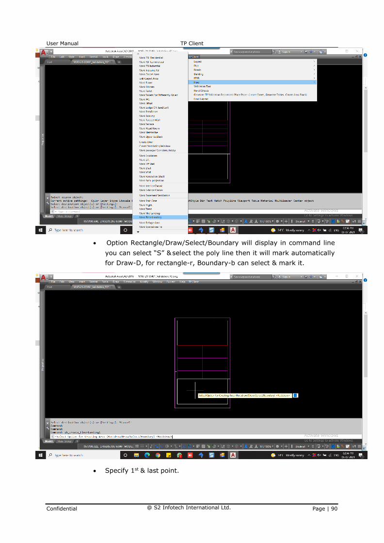
• Click on TP Client menu Floor Mark Floor Landing.
User Manual TP Client
Confidential @ S2 Infotech International Ltd. Page | 90
• Option Rectangle/Draw/Select/Boundary will display in command line
you can select “S” & select the poly line then it will mark automatically
for Draw-D, for rectangle-r, Boundary-b can select & mark it.
• Specify 1st & last point.

User Manual TP Client
Confidential @ S2 Infotech International Ltd. Page | 91
• Click on TP Client menu Floor Mark Flight.

User Manual TP Client
Confidential @ S2 Infotech International Ltd. Page | 92
• Option Rectangle/Draw/Select/Boundary will display in command line
you can select “S” & select the poly line then it will mark automatically
for Draw-D, for rectangle-r, Boundary-b can select & mark it.
• Specify 1st & last point.

User Manual TP Client
Confidential @ S2 Infotech International Ltd. Page | 93
User Manual TP Client
Confidential @ S2 Infotech International Ltd. Page | 94
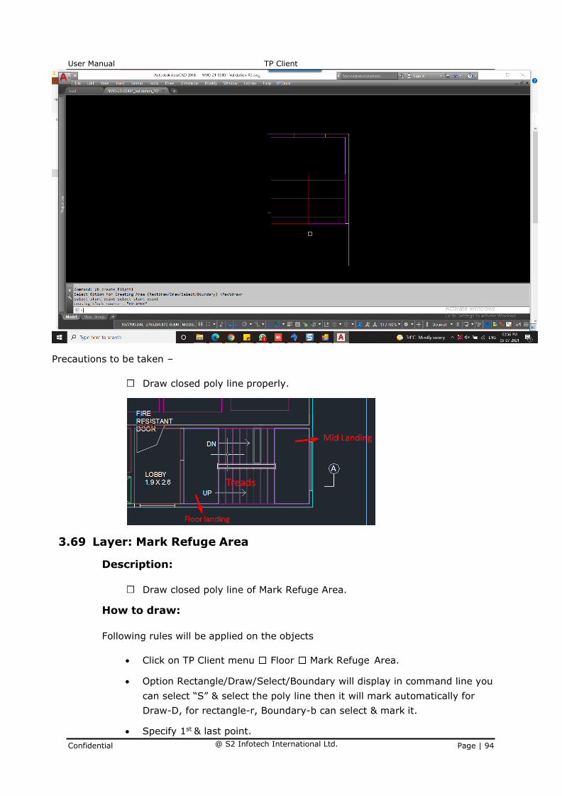
Precautions to be taken –
Draw closed poly line properly.
3.69 Layer: Mark Refuge Area
Description:
Draw closed poly line of Mark Refuge Area.
How to draw:
Following rules will be applied on the objects
• Click on TP Client menu Floor Mark Refuge Area.
• Option Rectangle/Draw/Select/Boundary will display in command line you
can select “S” & select the poly line then it will mark automatically for
Draw-D, for rectangle-r, Boundary-b can select & mark it.
• Specify 1st & last point.
User Manual TP Client
Confidential @ S2 Infotech International Ltd. Page | 95
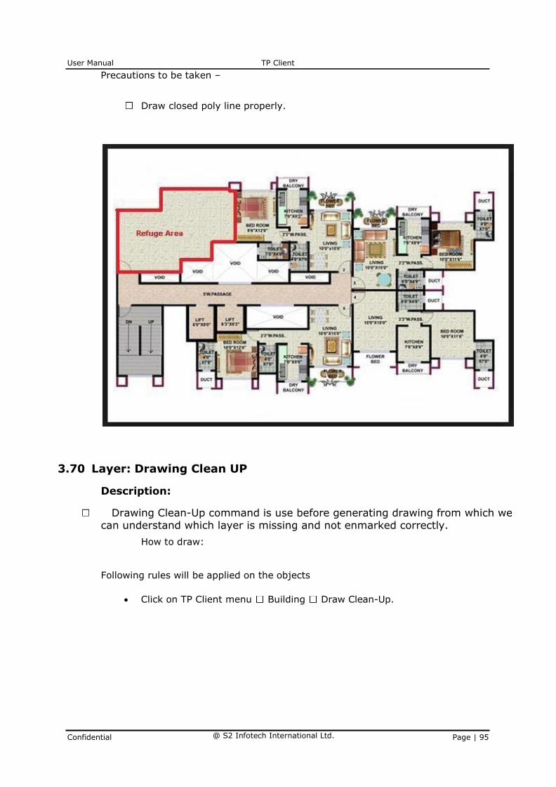
Precautions to be taken –
Draw closed poly line properly.
3.70 Layer: Drawing Clean UP
Description:
Drawing Clean-Up command is use before generating drawing from which we can understand which layer is missing and not enmarked correctly.
How to draw:
Following rules will be applied on the objects
• Click on TP Client menu Building Draw Clean-Up.

User Manual TP Client
Confidential @ S2 Infotech International Ltd. Page | 96
• This command is used when we draw unwanted lines been drawn which
need to be removed for better look so, use this command for the clear
markings.

User Manual TP Client
Confidential @ S2 Infotech International Ltd. Page | 97
• Precautions to be taken –
Use this Drawing Clean-Up command properly.