S-SERIES BIAS LEVEL I - Krell · PDF fileINTRODUCTION Thank you for your purchase of the KRELL...
24
~NALOG AND DIGITAL PRODUCTS S-SERIES I BIAS LEVEL I 04 0 40 O~ ~0 01 10 KSA-100S / 200S/300S OWNER’S REFERENCE
Transcript of S-SERIES BIAS LEVEL I - Krell · PDF fileINTRODUCTION Thank you for your purchase of the KRELL...
~NALOG AND DIGITAL PRODUCTS
S-SERIES
I BIAS LEVEL I04 0 40
O~ ~0
01 10
KSA-100S / 200S/300S OWNER’S REFERENCE

INTRODUCTION
Thank you for your purchase of the KRELL KSA-100S/200S/300S poweramplifier. These amplifiers represent the latest evolution in amplifiertechnology, matching unprecedented performance with convenience notobtainable from most high performance audio designs.
Throughout this Reference we will refer to all three of the amplifiers as KSA.All three amplifiers operate identically, while their sonic characteristics,specifications, and dimensions vary. Specific differences will be describedin detail.
To obtain the best performance from your KSA, careful attention should bepaid to placement, installation and operation. A thorough understanding ofthese details will help insure satisfactory operation and long life for the KSAand related system components.
This Owner’s Reference is divided into several sections, each designed toperform a different function. As you read through it you will become betteracquainted with the features and functions that make the KSA seriesamplifiers a superb value. A Question and Answer section is also includedwhere answers to common questions are provided. Should you have anyquestions or suggestions please feel free to contact your authorized dealeror the KRELL staff for assistance.
In the unlikely event that your KSA should require service, you will bepleased to know that it is backed by a comprehensive Customer Satisfactionpolicy and one of the most advanced service facilities in the industry. Fordetailed information on the terms and conditions of service, please refer tothe Warranty and Service section of this Reference, Warranty RegistrationCard, and your authorized KRELL Dealer or Distributor.
PAGE 2

TABLE OF CONTENTS
4 UNPACKING
5 LOCATION AND REMOTE TURN-ON
6 CABINETRY AND AC POWER CONSIDERATIONS
7 AMPLIFIER FEET AND REMOTE MASTER/SLAVE CONNECTIONS
9 INPUT AND OUTPUT CONNECTIONS
12 AMPLIFIER OPERATION
13 TURN-ON DESCRIPTION
14 SYSTEM NOISE
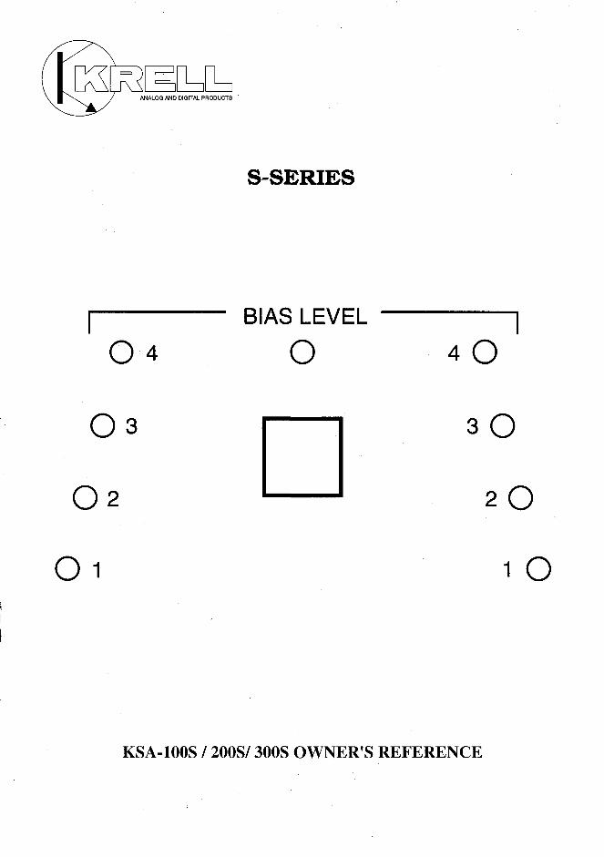
15 BIAS LEVEL METER
16 FRONT PANEL METER BUTTON
17 REMOTE CONTROL FUNCTIONS
18 PROTECTION CIRCUITRY AND TROUBLESHOOTING STEPS
20 QUESTIONS AND ANSWERS
22 SPECIFICATIONS
23 WARRANTY AND SERVICE INFORMATION
PAGE 3

UNPACKING
NOTE: Due to the extreme weight of the KSA amplifiers, it is strongly advisedthat unpacking and placement is completed by at least two individuals.
1. Open the box.
2. Fold back the flaps on all four sides of the box and carefully roll it over onto the exposed end.
3. Pull the box straight up and off exposing the foam packing material.
4. Pull the foam piece from the exposed end of the amplifier.
5. Roll the amplifier carefully onto its handles and remove the second pieceof foam.
The following items will now be visible:
iiii4or5
KSA stereo amplifierRemote controlWarranty cardAC power cordRubber feet bottoms (KSA-300S has 5 feet)
NOTE: If any’ of these items are not included, please contact your authorizeddealer immediately for assistance.
6. Remove the plastic bag from the amplifier.
NOTE: Save all packing materials. If you must ship your KSA in the future,repack the unit in its original packaging to prevent transit damage. Shouldthe unit require service, send the remote control and AC power cord with theamplifier.
CAUTION: Do not connect the power cord to the AC mains before completingthe Installation section.
PAGE 4
BASIC INSTALLATION
LOCATION
Place the KSA on a firm level surface away from excessive dirt or moisture.When using custom racks or cabinetry, keep in mind the weight andventilation requirements for these amplifiers. Ideally the amplifier should beplaced as close to the speakers as possible. It is preferable to run longbalanced interconnect cables to the amplifier and keep speaker cable lengthto a minimum. Speaker cable adds impedance to the load the amplifier mustdrive, regardless of the cable’s gauge. All KRELL amplifiers will drive thelowest impedances with ease, but when impedance is added due to longcable lengths, amplifier power is literally wasted in driving the cable. Longspeaker cables reduce the maximum power that can be delivered to thespeakers.
REMOTE TURN-ON INSTALLATION
Some installations do not have adequate space or arrangement flexibility forthe amplifier to be placed near the speakers. To allow for this, the KSA
¯ amplifiers can be turned On or Offfrom a room other than the listening room.This type of amplifier placement is referred to as Remote Installation. TheKSA can be placed in a room or space close to the speakers, but out of sight,and turned On and Off from the listening room. There is a provisioninternally to allow the amplifier to be controlled from a wall AC receptacleand not from the front panel power switch or remote control. We suggest astandard wall switch be mounted in the listening room to control an ACpower outlet dedicated to the power amplifier. This can be accomplished byan electrician. Please contact your dealer for assistance.
NOTE: When set-up for remote turn-on, the front panel power switch will notoperate, nor will the power switch on the remote control. The meter switcheson the front panel and remote are not affected and will operate normally.
NOTE: Remember to keep speaker cable lengths to a minimum.
PAGE 5

BASIC INSTALLATION
CABINETRY CONSIDERATIONS
High bias amplifiers dissipate much of the power they consume in heat.Because the KSA- 100S/200S/300S utilize Sustained Plateau Biasing, theyremain cool when not in use. When the KSA is in use, it can become quitehot. Therefore, the KSA should be installed in a location that providesunobstructed ventilation. If you must install the unit on shelves or in acabinet, extra ventilation may be necessary. This often can be accomplishedwith cabinet shelf spacing or unit location. In more extreme instances theuse of small fans can aid in removing excessive heat from internal spaces.Consult your dealer for assistance.
Generally, with the front and rear of a cabinet open, 3-4 inches of clearanceon each side and 8 inches of vertical clearance, the amplifier should haveadequate ventilation.
The KSA amplifiers have very large power supplies. As a consequence theamplifiers are quite heavy. When purchasing a rack or cabinet, keep weightin mind. Most racks are not capable of withstanding the weight of theseunits.
The exact weight and dimensions for the KSA-100S/200S/300S are in theSpecifications section of this manual.
AC POWER CONSIDERATIONS
The KSA should have a dedicated 20 amp line and should only be operatedwith the power cord supplied. Use of other power cords may damage theamplifier and void its warranty. Please consult KRELL or your dealerBEFORE using any devices designed to alter or stabilize the AC power for theKSA. AC line filters and/or stabilizers must meet or exceed the powertransformer size in the amplifier. As an example, the line conditioner willrequire a supply reservoir greater than 2800 VA to condition a KSA-200S.If you have any questions about placement or AC power conditions, pleaseconsult KRELL.
PAGE 6

BASIC INSTALLATION
AMPLIFIER FEET
The feet on the KSA can be used in several different ways. They are made frommachined Delrin and are supplied with separate threaded rubber bottoms.The rubber bottoms can be screwed into the feet for protection of fragilesurfaces such as hardwood floors or furniture. For use on rugs, werecommend using the feet without the rubber bottoms. KSA feet can alsoaccept the KRELL AMDs (Acoustic Mass Damper). The AMD is a type spiked foot that threads into the bottom of the foot. These improve theamplifier’s sonic performance in most installations and are particularlyeffective on carpeted floors. Please contact your dealer or KRELL with anyquestions.
REMOTE, MASTER/SLAVE CONNECTIONS - LINKING MULTIPLEAMPLIFIERS
There are two Remote connectors on the back of the KSA labeled Master andSlave provided for linking multiple amplifiers together. When the Master/Slave cables are connected to each of the amplifiers involved, their meterfunction controls and On/Off capabilities will be linked and controlled fromone amplifier.
Select the amplifier that you want to receive operation commands. Thatamplifier will be the Master. Follow the instructions below for connecting theamplifiers. Consider the Master receptacle the output and the Slave recep-tacle the input.
1. Turn all of the amplifiers Offand unplug them from the AC wall receptacle.Plug the amplifiers back in but do not turn them on before starting. Thisensures all amplifiers are synchronized when the cabling is connected.Connect one end of the linking cable to the Master output on the back panel.
2. Connect the other end of the linking cable to the Slave Input on the secondamplifier.
3. To synchronize three amplifiers, connect a second linking cable to theMaster output on the second amplifier. Connect the remaining end to theSlave input on the third amplifier.
PAGE 7

BASIC INSTALLATION
4. Connect additional amplifiers as described in step 3.
5. When the cables are all in place, point the remote control at the amplifierdesignated as Master and press the Power button. The amplifiers will all turnon at the same time.
The meter display for each amplifier may vary. Manually change the meterdisplay via the front panel until all of the meters match. The amplifier willremember the meter setting when cycled On/Off via the remote control orfront panel switch. If the unit is unplugged the memory will not remain andthe meters may need to be resynchronized. When linked and synchronizedcorrectly, ON/OFF and meter functions will happen simultaneously onlywhen the remote control is used.
NOTE: Each individual amplifier canbe turned ON/OFF and have meterfunctions changed via the front panel separately. If you change an individualamplifier’s function, it needs to be manually changed back to follow thefunctions of the other amplifiers so the synchronization remains intact.
NOTE: Contact your dealer or KRELL Industries to obtain remote cablelinks.
PAGE 8

CONNECTIONS
INPUT AND OUTPUT CONNECTIONS
CAUTION: When making connections to this component or any other, makesure the power amplifier is OFF and the preamplifier is in the MUTE orSTAND-BY mode.
The wiring to and from the amplifier, and all components in, general, shouldbe arranged in a neat, organized manner. Specifically, AC wires should beseparated from audio wires. This practice avoids hum or other unwantednoise from being induced into the system.
1. Connect the speaker cables to the amplifier’s output terminals.
The KSA utilizes two custom sets of parallel binding posts for the left andright channels respectively. This configuration makes cable connectionsand bi-wiring simple. The binding post will only accept a spade lug or ringterminal of proper inner radius. Bare wire, banana lugs or pins will not work.Each binding post is labeled either (+) or (-) between the sets of posts on rear panel. The (+) sign between the binding posts indicates the positiveoutput terminal. This is commonly referred to as red or hot. The (-) signbetween the binding posts indicates the negative output terminal. This iscommonly referred to as black or ground.
CAUTION: Make sure all cable terminations are of the highest quality, freefrom frayed ends, shorts or cold solder joints.
2. Connect the interconnect cables from your preamplifier to the input of theKSA.
The KSA has balanced and single-ended inputs ’. The balanced inputs use 3-pin XLR connectors and the single-ended inputs use standard RCA connec-tors. We recommend use of balanced interconnects sonically, and electricallybecause of their ability to reduce noise and not incur significant sonic lossdue to extreme cable lengths.
CAUTION: Use only one input to the amplifier at a time. The KSA is shippedwith shorting pins in the XLR inputs. These pins should remain in the XLRinputs if you are operating the KSA in the single-ended mode. When theshorting pin is inserted, pin 1 and pin 3 are shorted together. The shortingpins must be removed to connect the KSA for balanced operation.
PAGE 9

CONNECTIONS
The pin assignment for the XLR is:pin 1 = shield (ground)pin 2 = non-inverting input (hot)pin 3 = inverting input
NOTE: The RCA center conductor for each channel is wired in parallel withpin 2, the non-inverted input. Only one of these inputs should be connectedto a preamplifier. Do not attempt to use the single-ended and balancedinputs simultaneously.
3. Insert the AC power cord into the receptacle located on the back of theKSA. Insert the other end into the wall AC receptacle. (Refer to the BasicInstallation section, for AC power requirements)
4. The amplifier is now ready for operation. Should you have any questionsregarding system set-up, contact your dealer or KRELL Industries.
PAGE 10

CONNECTIONS
LOUDSPEAKERS
KSA AMPLIFIER
R L
PAGE 11

OPERATION
AMPLIFIER OPERATION
Understanding the ’operation of the amplifier is very easy. Equally importantis an understanding of the care that should be exercised when operating thesystem as a whole, in relation to the enormous power output of the KSA.Simple mistakes, such as switching between active sources without mutingthe preamplifier output, or bumping/miscuing a cartridge, can generatelarge transients at low frequencies. With this type of transient the KSA cangenerate enough power to damage most loudspeakers. All switching ofsources should be done with the preamplifier level either muted or fullyattenuated. Inputs to the amplifier should not be changed while theamplifier is on.
NOTE: Care must be taken when setting high playback levels. Because oftheir tremendous reserve of clean power, KRELL amplifiers safely drivespeakers to higher sound pressure levels than other amplifiers. This alsomeans driving the speakers to their limit. Always turn the level down at thefirst sign of distortion.
When turning the system off, turn the volume on the preamplifier all the waydown or put it into the MUTE or STAND-BY position. Turn the amplifier off.This avoids the possibility of a turn-off transient from another componentgetting to the speakers. Because of the tremendous output power in the KSAamplifiers, the amplifier should not be turned on or off with music playing.This can arc the speaker output relays and potentially damage the amplifier.
PAGE 12

OPERATION
DESCRIPTION OF TURN-ON SEQUENCE
When turning on the system, the amplifier should always be last.
The KSA On/Off switch is part of a multi-level turn-on circuit that goesthrough several steps of protection. Upon turn-on, the amplifier’s outputsare not connected to the speakers. After the protection circuits havedetermined that the unit has completely stabilized, the speaker relays willengage. You will hear a click at this point. The LED’s in the bias meter willstart at the highest bias level upon turn-on and slowly work their way downto no-bias. This process takes approximately 1 minute. The amplifier isready to use once the bias meters have settled to the no-bias level.
1. Push the black Power button on the amplifier front panel to turn it on.The Power button is the larger of the two buttons at the top of the face plate.The blue LED labeled POWER in the center of the bias meter will illuminatewhen the Power button is depressed. The amplifier will progress through theturn-on sequence described above.
2. With the preamplifier in the Mute position, or volume control fullyattenuated, select a source. Turn the volume control up to your desiredlistening level.
3. Enjoy.
PAGE 13

OPERATION
SYSTEM NOISE CONSIDERATIONS
AC grounding often becomes critical when connecting high performanceaudio gear. When mixing and matching audio components, each with theirown ground potentials, a low frequency hum can become present in one orboth speakers. This can often occur when introducing a new component intothe system.
If there is a low frequency hum coming from the speakers when the KSA isconnected into the system, follow these simple trouble-shooting steps:
1. Check all of the input and output connections, making sure they are ofsound construction. With the amplifier off, remove the interconnect wiringand tum the amplifier back on. If the hum disappears, shut the amplifieroff and reinsert one of the interconnect cables and turn the amplifier backon. If the hum is present with one or both interconnects inserted, there maybe a defective cable. Have the interconnect cabling checked before proceed-ing.
2. If the interconnect proves to be fine, more than likely you are experiencinga ground loop. This can often easily be eliminated. Contact your dealer orKRELL for assistance.
PAGE 14
OPERATION
BIAS LEVEL METER
The KSA amplifiers utilize Sustained Plateau Biasing, a proprietary KRELLdesign. The Bias display meter on the front panel of the amplifier displayswhich level of bias the amplifier is utilizing. Unlike sliding bias designs,Sustained Plateau Bias only changes level when the demand situationrelative to input and source material changes. The signal passes through asection called an Anticipator circuit. Once the level of bias is determined bythe Anticipator circuit, it automatically biases the output ~f the amplifierbefore the signal is passed through the output stage. The Anticipator circuitis several times faster than the output stage itself. This technique insuresall signal is passed through the amplifier in pure Class A operation. If theamplifier only requires a low level of Class A bias, the amplifier will bias itselfto use only the amount of Class A power necessary to the demandparameters. Should the demand parameters exceed the bias level theamplifier is presently working under, the amplifier will increase its bias tothe next level to allow all signal to come through in Class A operation. If thedemand parameters are less then the bias level indicates for more than 15-20 seconds, the amplifier will drop to the next lowest bias level.
The bias levels are indicated by appropriate LEDs in the faceplate meterdisplay as they are activated.
Should the demand parameters reach a point at which the temperature ofthe external heatsink reaches approximately 80 degrees Celsius, the last twolevels of bias 3 and 4 will be disabled until the heatsink temperature dropsto a safe operating level. The overall output power of the amplifier is notchanged when this occurs, only the amount of class A power. You will noticethe LEDs corresponding to the top two levels of bias will not illuminate. TheLEDs for levels 3 and 4.will come back on when the heatsink temperatureis at safe operating levels. This temperature fluctuation will not harm theamplifier. It is provided for consumer safety in a home listening environ-ment.
PAGE 15

OPERATION
FRONT PANEL METER BUTTON
A small button beneath the Power button on the front panel controls BiasMeter display illumination. When engaged, the meter display will no longerindicate bias levels; only the Blue pilot LED will be visible. The Bias Levelmeter can also be turned on or off via the remote control.
PAGE 16

OPERATION
REMOTE CONTROL FUNCTIONS
The KSA-100S/200S/300S are the first high performance amplifiers toutilize remote control functions. The amplifiers can be switched on or offandthe meter function can be changed from your listening position via the hand-held remote control.
The KSA remote control duplicates the front panel switches on the amplifi-ers. The Power button will turn the amplifier on and off, while the Meterbutton will choose between a full bias meter display or no bias LEDillumination.
When the amplifier is switched On, the Blue POWER LED and Bias LevelMeter display will illuminate. When the amplifier is switched Off, no LEDswill be illuminated.
When the Bias Level Meter is turned off, no LEDs will be visible except forthe blue pilot LED. When the Bias Meter display is on, the bias level will bedisplayed with the appropriate LEDs.
BATTERY INSTALLATION
NOTE: Batteries should be replaced when the KSA functions from the remotecontrol become intermittent.
1. Remove the four hex head screws from the back of the remote control.2. Remove the back plate to expose the battery storage compartment.3. Replace batteries (Refer to the polarity drawing while inserting thebatteries)4. Replace the back plate and insert the four hex head screws.
PAGE 17
OPERATION
PROTECTION CIRCUITRY
There are no fuses in the KSA. The amplifier is protected by a series of non-intrusive, opto-coupled circuits that constantly evaluate the amplifier’soperation. Appropriate protective action exists for DC conditions, shortcircuit, oscillation, AC power anomalies, high ground resistance and out-of-phase ground. Collectively, the protection circuitry is designed to avoiddamage to the amplifier or speakers caused by other defective components,faulty wiring, mishandling of the system or amplifier failure. When theprotection circuit is engaged, the amplifier will shut off and short its output.The amplifier can be turned on after resolving either the input or outputproblem.
SIMPLE TROUBLE-SHOOTING STEPS
Follow these steps when trying to resolve the cause of potential amplifierrelated failure. If the amplifier will not turn on, or stay on:
1. Disconnect all input and output connections. Once this is completed, tryturning the amplifier on.
If the amplifier does not come on, check the circuit breaker on the backpanel. If the circuit breaker has popped out or appears to be more extendedthan usual, reset the breaker switch by pressing it back in. If the amplifierstill does not come back on, call KRELL.
If the amplifier does not come on and the circuit breaker on the back of theunit seems normal, check the house circuit breaker or fuse for the poweroutlet associated with the amplifier.NOTE: When turning the amplifier on and off between cable checks, let theamplifier settle for at least 45 seconds before turning it back on.
2. If the amplifier turns on and appears to work properly again, turn theamplifier off and reconnect the output speaker cables for one channel only.If the amplifier turns on normally, reconnect the other channel outputspeaker cables.
PAGE 18
OPERATION
Should the amplifier turn off when either output cable is connected, theproblem is cable or speaker related. Check to make sure there are goodmechanical connections on the speaker cabling and there are no frayed endsor wires shorting the output terminals together. Have your speaker cableschecked and repaired if necessary by your dealer before proceeding.
3. If the amplifier turns on normally with only the speaker cables connectedto the output, turn the amplifier off and reconnect the interconnect cablefor one channel only. If the amplifier turns on normally reconnect the otherchannel’s interconnect cable and turn on the amplifier.
Should the amplifier turn off when either interconnect cable is connected,the problem is cable, preamp or source component related.
Check to make sure there are good mechanical connections on the intercon-nect cabling and there are no broken terminations. Have your interconnectcables checked and repaired if necessary by your dealer before proceeding.
Should the cabling from the preamplifier to the amplifier input be functional,check source component interconnects. Should the interconnects prove tobe sound throughout the system, have the preamplifier and any suspectsource components checked. The source components should be checkedindividually through the preamp, should the preamp prove to work properly.
4. Should all of the system components, cabling and AC power requirementsbe sound and the amplifier continues to not work, call your dealer,distributor or KRELL to arrange for service. Service can be handled directlythrough KRELL. Should you need a KRELL component serviced please callthe factory to discuss the problem and obtain a Return Authorizationnumber (RA#) and shipping information.
PAGE 19
QUESTIONS AND ANSWER
Q. Should I leave the KSA on at all times?
A. Because of Sustained Plateau Bias, the KSA can be left on at all timeswithout fear of damage, excessive heat or excessive power consumption. TheKSA amplifier however, is designed to be turned On/Off, and can do sowithout degradation. The amplifier will work at full performance withinminutes of turn-on.
Q. When I push the power button on the front of the KSA, the amplifierdoesn’t turn on. What should I do?
A. Check the input and output connections, then retry the amplifier. Checkthe circuit breaker on the back of the unit and reset it if necessary. Consultthe protection circuitry section of this manual for more detailed trouble-shooting procedures.
Q. When I turn the amplifier on there is a loud hum through the speakers.There wasnever a hum before the KSA was in the system. What should I do?
A. Often when a new component is introduced into an audio system a hummay become present. This is often caused by a ground loop in the system orby defective cabling. Check your cables to and from the amplifier. If the humpersists, contact your dealer or the KRELL staff for assistance.
Q. Can I use special audio power cords on the KSA?
A. You can experiment with special power cords as long as they are groundedon both ends, meet the amplifier’s 20 amp power requirement, and are safetyapproved by organizations like CSA or UL. The use of them, however, is notrecommended without first consulting your dealer or the KRELL factory.
Q. My speakers only have one set of binding posts. Which set of binding postsshould I use on the amplifier?
A. The two binding posts for each channel on the KSA are the same pointelectrically. You can use either the top set of posts or the bottom set. Theysound and work the same.
PAGE 20

QUESTIONS AND ANSWER
Q. My speakers axe only rated for 150 watts, is the KSA-200 or KSA-300going to be too much power for them?
A. Seldom do you break a speaker by over powering it. Usually lower poweredamplifiers will clip driving a loud speaker during heavy demand situationsand consequentially damage the speaker. KRELL amplifiers can breakspeakers, but a responsible listener should know the limitations of his/hersystem and exercise caution. The higher powered KRELL amplifiers willsound better because of the increased control over the speaker. Should youhave any questions contact your dealer or the KRELL staff for assistance.
Q. When I connected the KSA to my system with the single-ended inputs aloud buzz came through my speakers. Is the amplifier broken?
A. The KSA has special shorting pins in the XLR inputs that enable theamplifier to function properly with the single-ended inputs. If the shortingpins are not inserted between pin 1 and 3 the 180 degree input will be opento excess noise.Otherwise single-ended inputs will work fine with the unit. The performanceof the amplifier is much improved when using the balanced inputs.
PAGE 21
SPECIFICATIONS
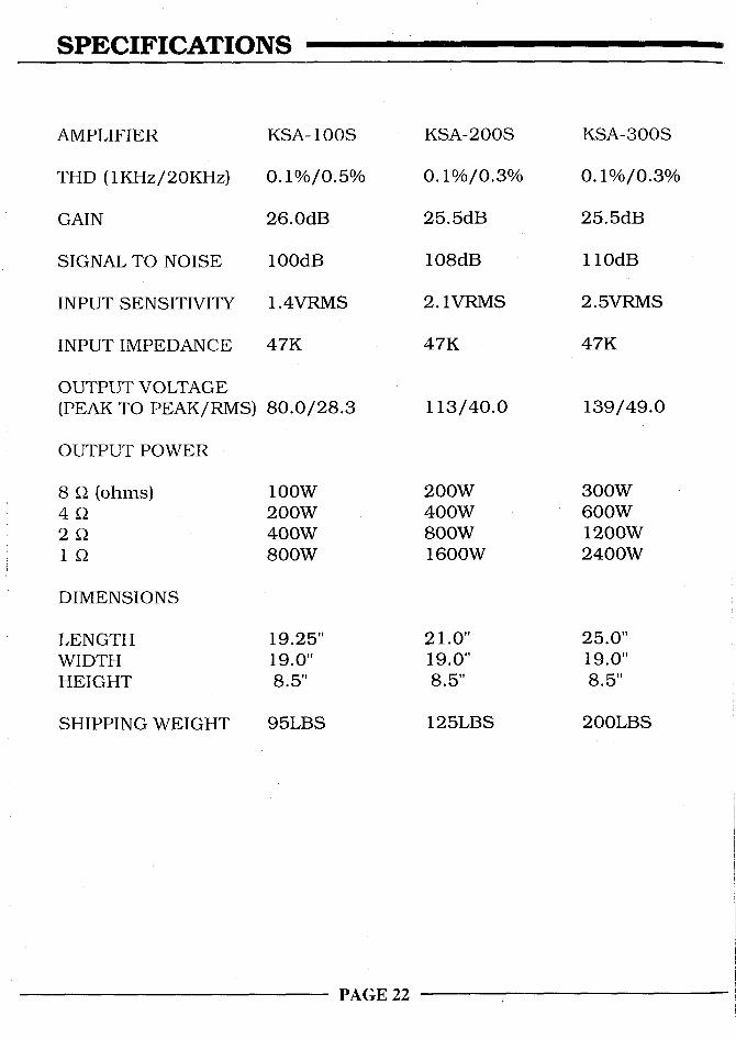
AMPLIFIER
THD (1KHz/20KHz)
GAIN
SIGNAL TO NOISE
INPUT SENSITIVITY
INPUT IMPEDANCE
OUTPUT VOLTAGE(PEAK TO PEAK/RMS)
OUTPUT POWER
8 gl (ohms)
it]
DIMENSIONS
LENGTHWIDTHHEIGHT
SHIPPING WEIGHT
KSA- 100S
0.1%/0.5%
26.0dB
100dB
1.4VRMS
47K
8O.0/28.3
100W200W400W800W
19.25"19.0"8.5"
95LBS
KSA-200S
0.1%/0.3%
25.5dB
108dB
2.1VRMS
47K
113/40.0
200W400W800W1600W
21.0"19.0"8.5"
125LBS
KSA-300S
0.1%/0.3%
25.5dB
110dB
2.5VRMS
47K
139/49.0
300W600W1200W2400W
25.0"19.0"8.5"
200LBS
PAGE 22

WARRANTY AND SERVICE
THERE ARE NO USER-SERVICEABLE PARTS INSIDE THE KSA-100S/200S/300S.
The KSA-100S/200S/300S has a limited and transferable warranty of five years for partsand labor. The warranty period begins on the date of retail purchase, as noted on the retailsales slip provided by an authorized KRELL Dealer or Distributor, or on the warrantyregistration card sent to KRELL. In the event adequate proof of purchase date is unavailable,the warranty period will begin on the date the unit was originally shipped from the factory.The original ship date can be determined by KRELL from the serial number.
The warranty for KRELL products is valid only in the country to which they were originallyshipped, through the authorized KRELL Distributor for that country, and at the factory.There may be restrictions on or changes to KRELL’s warranty because of regulations withina specific country. Please check with your Distributor for a complete understanding of thewarranty in your country.
Freight to the factory is your responsibility. Second day return freight within the UnitedStates is included in the warranty. If you have purchased your KRELL product outside theStates and wish to have it serviced at the factory, all freight and associated charges to thefactory are your responsibility. KRELL will pay return freight to the US-based freightforwarder of your choice. Freight and other charges to ship the unit from the freightforwarder to you are also your responsibility.
The operating voltage of this unit is determined by the factory and can only be changed byan authorized KRELL Distributor or at the factory. The voltage for the KSA-100S/200S/300S in the USA can not be changed until six months from the original purchase date. Anyunauthorized voltage conversion, disassembly, component replacement, perforation ofchassis, updates, or modifications performed to the unit will void the warranty.
KRELL is not responsible for any damage incurred in transit. KRELL will file claims fordamages as necessary for units damaged in transit to the factory. You are responsible tofile claims for shipping damages during the return shipment.
The use of any packing material other than original is not recommended. KRELL may, atits discretion, pack a unit in new packing for the return shipment and bill you for suchpacking if the unit was packed in non-standard packing or the original packing is sodamaged as to be unusable.. Should you need to purchase additional packaging pleasecontact your authorized KRELL Dealer, Distributor or KRELL for assistance.
IMPORTANT: If you think there are problems with your unit, please contact your Dealer,Distributor, or the factory immediately. Do not return any unit to KRELL for repair withoutfirst calling to discuss the problem and to obtain a Return Authorization number.
PAGE 23

KRELL45 Connair Road Orange, CT 06477
SALES (203) 799-9954 FAX (203) 799-9796© 1994 KRELL INDUSTRIES
(KSA9406)


![Lenovo Ideacentre 300S Hmm 20151104 ideacentre 300S Series … · 2015. 11. 4. · ideacentre 300S Series Hardware Maintenance Manual Machine Types: 90DQ [300S-11IBR/Energy Star]](https://static.fdocuments.in/doc/165x107/60cfbab2aece5111e35d5c92/lenovo-ideacentre-300s-hmm-20151104-ideacentre-300s-series-2015-11-4-ideacentre.jpg)