
RZ/A1LU Group
28
Application Note R01AN3356EG0210 Rev.2.10 Page 1 of 26 Nov.16.20 RZ/A1LU Group Stream it! - RZ Web Server Demonstration Introduction This application note describes how to configure the Stream it! - RZ V2 kit (hardware) and install the tools to run the Oryx Web Server demo supplied as part of the Stream it! - RZ kit The application, which is running on the Stream it! - RZ V2 board, hosts a web server implementation using the TCP/IP stack from Oryx. By default, the contents of the website which is hosted on the Stream it! - RZ hardware provides the following pages: • Page 1 Ajax Demo 1 This demonstration application reads the position of the potentiometer and acquires raw acceleration data from the multi-axis MEMS. This web page uses Ajax (Asynchronous JavaScript and XML) to update itself periodically. • Page 2 Ajax Demo 2 The cube follows the inclination of the board. Just tilt the board up with your hand! The joystick and the potentiometer can also be used, respectively for translation and spinning. • Page 3 CGI Demo The web server supports SSI (Server-Sides Includes) and CGI scripting for dynamic contents. The following properties are dynamically generated each time the page is refreshed (press F5). If your system supports IPv6, try to access the server using its IPv6 link-local address or global address and discover your own IPv6 host address! • Page 4 SMTP Demo If your LAN is connected to the Internet, this form allows you to send an e-mail. Fill in the required fields and press the ‘Send’ button. It may take a few seconds to complete the operation if your SMTP server requires secure SSL/TLS connection. The hardware needed to follow this application note includes: • Windows TM 7/ 8/ 8.1/10 compatible PC • Stream it! - RZ V2 Kit including display • USB to micro USB Cable • Segger J-Link Lite Debugger The software components that will be obtained while following this application note include: • e 2 studio (Recommended latest version) • GNU ARM NONE Embedded Compiler (Version 16.01) This document refers to many third party website resources. These websites are not controlled by Renesas Electronics, and we are therefore unable to offer support for these resources. The following documents apply to the RZ/A1LU based Renesas Stream it! - RZ V2. Please refer to the latest versions of these documents. Document Type Description Document Title Available from Hardware Manual Provides technical details of the RZ/A1LU microcontroller. RZ/A1L Group User’s Manual: Hardware https://www.renesas.com/en- eu/products/microcontrollers- microprocessors/rz/rza/rza1lu.html Target Device RZ/A1LU Group
Transcript of RZ/A1LU Group

Application Note
R01AN3356EG0210 Rev.2.10 Page 1 of 26 Nov.16.20
RZ/A1LU Group Stream it! - RZ Web Server Demonstration Introduction
This application note describes how to configure the Stream it! - RZ V2 kit (hardware) and install the tools to run the Oryx Web Server demo supplied as part of the Stream it! - RZ kit
The application, which is running on the Stream it! - RZ V2 board, hosts a web server implementation using the TCP/IP stack from Oryx.
By default, the contents of the website which is hosted on the Stream it! - RZ hardware provides the following pages:
• Page 1 Ajax Demo 1 This demonstration application reads the position of the potentiometer and acquires raw acceleration data from the multi-axis MEMS. This web page uses Ajax (Asynchronous JavaScript and XML) to update itself periodically.
• Page 2 Ajax Demo 2 The cube follows the inclination of the board. Just tilt the board up with your hand! The joystick and the potentiometer can also be used, respectively for translation and spinning.
• Page 3 CGI Demo The web server supports SSI (Server-Sides Includes) and CGI scripting for dynamic contents. The following properties are dynamically generated each time the page is refreshed (press F5). If your system supports IPv6, try to access the server using its IPv6 link-local address or global address and discover your own IPv6 host address!
• Page 4 SMTP Demo If your LAN is connected to the Internet, this form allows you to send an e-mail. Fill in the required fields and press the ‘Send’ button. It may take a few seconds to complete the operation if your SMTP server requires secure SSL/TLS connection.
The hardware needed to follow this application note includes:
• WindowsTM 7/ 8/ 8.1/10 compatible PC
• Stream it! - RZ V2 Kit including display
• USB to micro USB Cable
• Segger J-Link Lite Debugger
The software components that will be obtained while following this application note include:
• e2 studio (Recommended latest version)
• GNU ARM NONE Embedded Compiler (Version 16.01)
This document refers to many third party website resources. These websites are not controlled by Renesas Electronics, and we are therefore unable to offer support for these resources.
The following documents apply to the RZ/A1LU based Renesas Stream it! - RZ V2. Please refer to the latest versions of these documents.
Document Type Description Document Title Available from Hardware Manual Provides technical details of the
RZ/A1LU microcontroller. RZ/A1L Group User’s Manual: Hardware
https://www.renesas.com/en-eu/products/microcontrollers-microprocessors/rz/rza/rza1lu.html
Target Device RZ/A1LU Group

RZ/A1LU Group Stream it! - RZ Web Server Demonstration
R01AN3356EG0210 Rev.2.10 Page 2 of 26 Nov.16.20
Glossary AJAX Asynchronous JavaScript and XML
ARM Advanced RISC Machine
CGI Common Gateway Interface
COM Communications Port
DHCP Dynamic Host Configuration Protocol
FIQ Fast Interrupt Request
HTTP Hypertext Transfer Protocol
IDE Integrated Development Environment
IP Internet Protocol
IPV4 Internet Protocol Version 4
IPV6 Internet Protocol Version 6
IRQ Interrupt Request
JTAG Joint Test Action Group
LAN Local Area Network
LCD Liquid Crystal Display
LED Light Emitting Diode
MEMS Micro Electro Mechanical Systems
PC Personal Computer
QSPI Quad Serial Peripheral Interface
RAM Random Access Memory
RISC Reduced Instruction Set Computing
ROM Read Only Memory
RTOS Real Time Operating System
SMTP Simple Message Transfer Protocol
SPI Serial Peripheral Interface
SSI Server Side Includes
SSL/TLS Secure Sockets Layer / Transport Layer Security
TCP/IP Transmission Control Protocol / Internet Protocol
USB Universal Serial Bus
XML Extensible Markup Language

RZ/A1LU Group Stream it! - RZ Web Server Demonstration
R01AN3356EG0210 Rev.2.10 Page 3 of 26 Nov.16.20
Contents
Glossary ......................................................................................................................................................... 2
1. Overview ................................................................................................................................................. 4 1.1 Licenses................................................................................................................................................... 4 1.2 Oryx Streaming Media............................................................................................................................. 4 1.3 FreeRTOS ............................................................................................................................................... 5
2. Runtime Operation .................................................................................................................................. 5 2.1 Preparing Demonstration for Use ............................................................................................................. 5 2.2 Using the Demonstration ....................................................................................................................... 10
3. Evaluation of Software .......................................................................................................................... 14 3.1 IDE Requirements e2 studio ................................................................................................................... 14 3.2 e2 studio Installation .............................................................................................................................. 14 3.3 e2 studio Update ..................................................................................................................................... 16 3.4 Importing the Project into e2 studio ........................................................................................................ 17 3.5 Compiling the Software ......................................................................................................................... 19 3.6 Running the Software ............................................................................................................................ 19
4. Project Details ....................................................................................................................................... 21 4.1 Project Layout ....................................................................................................................................... 21 4.2 Runtime Environment ............................................................................................................................ 21 4.3 Startup Sequence ................................................................................................................................... 22
5. High Level Overview of Source Tree Key Components ....................................................................... 24
6. Further Reading ..................................................................................................................................... 25

RZ/A1LU Group Stream it! - RZ Web Server Demonstration
R01AN3356EG0210 Rev.2.10 Page 4 of 26 Nov.16.20
1. Overview This document aims to guide the user through opening, configuring and running the Web Server demonstration for the Stream it! - RZ V2 product.
The figure below shows the final configuration of the Stream it! - RZ hardware setup.
Network DHCP enabled Hub
Contentshosted on
Stream it! - RZViewed on PC
Stream it! - RZ power via USB
connected DHCP hub
Figure 1 Hardware Configuration of the Stream it! - RZ
Connections explained
• The PC is connected to a DHCP enabled wired network hub, to which the Stream it! - RZ is also connected.
• The Stream it! - RZ kit is assembled with the LCD screen connected to the connector fitted on the underside of the board near the top right hand side of the PCB (labelled ‘CN7’ and ‘LCD’).
• The Stream it! - RZ kit is powered via USB.
1.1 Licenses This sample application includes several third party code applications, each of these includes a licence allowing various use cases for the provided code. A summary of the licences can be found below:
Component Licence Restrictions
Oryx GNU GPL V2 or Later Reciprocal disclosure requirement for all source code.
FreeRTOS GNU GPL V2 (Modified with FreeRTOS Exception)
Modification allows use of FreeRTOS code in a product without disclosure of independent source code.
1.2 Oryx Streaming Media Oryx Embedded SARL: http://www.oryx-embedded.com have provided this demonstration of the web streaming capabilities of the RZ/A1LU on the Stream it! - RZ V2 product.

RZ/A1LU Group Stream it! - RZ Web Server Demonstration
R01AN3356EG0210 Rev.2.10 Page 5 of 26 Nov.16.20
A network interface is started providing a simple web server interface that provides access to the web site hosted on the Stream it! - RZ kit.
1.3 FreeRTOS Real Time Engineers Ltd: http://www.freertos.org/RTOS.html have provided the embedded Operating System (OS) for this demonstration code.
2. Runtime Operation This section details the Stream it! - RZ Web Server application. Specifically preparation for use, and how to interact with the demonstration application.
2.1 Preparing Demonstration for Use This demonstration uses software and tools provided in the Stream it! - RZ kit please ensure that product DVD media (D015524_25) supplied in this kit is available.
2.1.1. Hardware Setup
• Connect your JLink Lite debugger to the connector (marked ‘JTAG’ and ‘CN1’) on the Stream it! - RZ board
• Connect the USB cable between your PC and the JLink debugger
• Connect an ethernet cable from your network hub, to the RJ45 socket (marked ‘CN6’) on the Stream it! - RZ board
• Connect a USB cable between your PC and the Stream it! - RZ board. If the Stream it! - RZ is connected via USB to a PC, then emulation of a serial (COM) port for debug is provided. Please refer to section (2.1.4) for instruction on how to configure this serial connection.
• Apply power to the USB port (marked ‘CN10’ - next to the SD card socket) or press the reset switch (located above the ‘A’ of the Renesas logo on the board and marked ‘RESET’) to reset the device.
2.1.2. Downloading the Application Please note that a previous application may be installed on the Stream it! - RZ hardware so we must now install the application we wish to evaluate.
To update the application on the Stream it! - RZ board you must have installed the JLink debugger software.
To use this batch file you must have the Segger Jlink drivers installed on your PC.
The Segger home page is www.segger.com and the version of the drivers that were used during development of this application and therefore are guaranteed to operate correctly is JLink_V6.12J
• Insert the CD media supplied in this kit, or if the .ISO has been downloaded from the website, mount the image.
If the menu does not appear automatically in your browser, click on ‘setup.hta’

RZ/A1LU Group Stream it! - RZ Web Server Demonstration
R01AN3356EG0210 Rev.2.10 Page 6 of 26 Nov.16.20
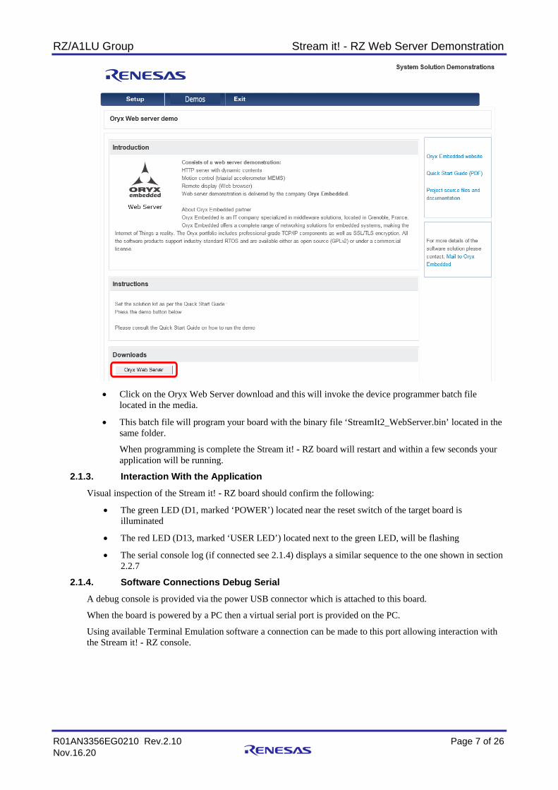
• Using the setup page (see above) click on ‘Demos’ in the menu bar
• Select the ‘Oryx embedded Web Server’ demonstration and the details page will be displayed.
RZ/A1LU Group Stream it! - RZ Web Server Demonstration
R01AN3356EG0210 Rev.2.10 Page 7 of 26 Nov.16.20
• Click on the Oryx Web Server download and this will invoke the device programmer batch file
located in the media.
• This batch file will program your board with the binary file ‘StreamIt2_WebServer.bin’ located in the same folder.
When programming is complete the Stream it! - RZ board will restart and within a few seconds your application will be running.
2.1.3. Interaction With the Application Visual inspection of the Stream it! - RZ board should confirm the following:
• The green LED (D1, marked ‘POWER’) located near the reset switch of the target board is illuminated
• The red LED (D13, marked ‘USER LED’) located next to the green LED, will be flashing
• The serial console log (if connected see 2.1.4) displays a similar sequence to the one shown in section 2.2.7
2.1.4. Software Connections Debug Serial A debug console is provided via the power USB connector which is attached to this board.
When the board is powered by a PC then a virtual serial port is provided on the PC.
Using available Terminal Emulation software a connection can be made to this port allowing interaction with the Stream it! - RZ console.

RZ/A1LU Group Stream it! - RZ Web Server Demonstration
R01AN3356EG0210 Rev.2.10 Page 8 of 26 Nov.16.20
It will be named ‘RSK USB Serial port’ and in this case has been allocated COM3.
The connection settings should be as follows:
Baud Rate 115200 Data Rate 8-bit Parity None Stop Bits 1 Flow Control None
2.1.5. Software Connections Wired Ethernet DHCP Connection
• Connect your PC and Stream it! - RZ board, to the same DHCP using an Ethernet cable(s)
• The LCD display can remain connected to the Stream it! - RZ board but it will not be used in this demonstration
• No additional software configuration is needed
2.1.6. Software Connections Wired Ethernet Fixed Ethernet Connection
• To specify a fixed IP in the demonstrations, when DHCP is not available
• An Ethernet hub can be used as long as the Ethernet connectivity between the Stream it! - RZ board and target PC is specified.
Setting PC Fixed Ethernet address:
• Disconnect your PC from the network
• Open your network properties • Select IPV4 properties
Make a note of the currently configured fixed IP settings. If you change them, you will need to return them to the original settings when you have finished.
• Set a unique IP address on the same domain as the Stream it! - RZ kit.
The Stream it! - RZ board uses the default IP address (192.168.0.161) when DHCP is not available. This address is set in the code.
• Press OK and reconnect the PC to the Ethernet switch. • Reset the Stream it! - RZ kit The IPV4 Address (192.168.0.161) will be used as the host address for the web server.

RZ/A1LU Group Stream it! - RZ Web Server Demonstration
R01AN3356EG0210 Rev.2.10 Page 9 of 26 Nov.16.20
Note:
The source code reference for default IP address (\StreamIt2_WebServer\src\renesas\configuration\config.h line 53).
2.1.7. Determining Host Address of Stream it!
• When DHCP is in use the IP address will be automatically assigned to the Stream it! - RZ kit and this address will be sent to the debug console log
• Connect a terminal to view the console output from the Stream it! - RZ kit (see 2.1.4)
• Reset the board and examine the console output using your terminal program. It should look similar to this:-
**********************************
*** CycloneTCP Web Server Demo ***
**********************************
Copyright: 2010-2015 Oryx Embedded SARL
Website: http://www.oryx-embedded.com
Contact: [email protected]
TCP/IP Stack Version: 1.6.1
Compiled: Jan 13 2017 15:27:24
Target: Stream It! RZ Renesas Kit (RZ/A1L)
Initializing BMA250...
Initializing EEPROM...
Loading user settings...
Failed to load user settings!
Web Server Demo
CliTask starting
Initializing DHCP client...
Starting DHCP client...
DHCP configuration:
Lease Start Time = 3s 806ms
Lease Time = 86400s
T1 = 43200s
T2 = 75600s
IPv4 Address = 192.168.0.11
Subnet Mask = 255.255.255.0
Default Gateway = 192.168.0.1
DNS Server 1 = 192.168.0.1
DNS Server 2 = 0.0.0.0
MTU = 1500
• The IPV4 Address (192.168.0.11) has been assigned to the Stream it! - RZ
• You are now ready to interact with the sample application
RZ/A1LU Group Stream it! - RZ Web Server Demonstration
R01AN3356EG0210 Rev.2.10 Page 10 of 26 Nov.16.20
2.2 Using the Demonstration Now that your environment is configured and your Stream it! - RZ board is programmed with the code, you can evaluate the application.
2.2.1. Connecting to the Web Server Using the IP address obtained above (see 2.1.7), open a web browser (Firefox or Chrome – Internet Explorer is not supported), and type it into the address bar and press [RETURN].
After a short delay the first page (out of 4) from the web server should be shown.
Navigation between the pages is achieved by pressing the left or right arrow buttons on the webpage.
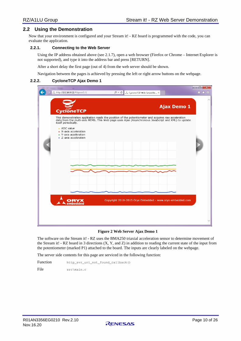
2.2.2. CycloneTCP Ajax Demo 1
Figure 2 Web Server Ajax Demo 1
The software on the Stream it! - RZ uses the BMA250 triaxial acceleration sensor to determine movement of the Stream it! - RZ board in 3 directions (X, Y, and Z) in addition to reading the current state of the input from the potentiometer (marked P1) attached to the board. The inputs are clearly labeled on the webpage.
The server side contents for this page are serviced in the following function:
Function http_svr_uri_not_found_callback()
File src\main.c

RZ/A1LU Group Stream it! - RZ Web Server Demonstration
R01AN3356EG0210 Rev.2.10 Page 11 of 26 Nov.16.20
2.2.3. CycloneTCP Ajax Demo 2
Figure 3 Web Server Ajax Demo 2
The software on the Stream it! - RZ uses the BMA250 triaxial acceleration sensor to determine movement of the Stream it! - RZ board in 2 directions (X and Y) in addition to reading the current state of the input from the potentiometer (marked P1) attached to the board.
These 3 inputs are then represented in movement and rotation of the cube on the webpage.
The server side contents for this page are serviced in the following function:
Function http_svr_uri_not_found_callback()
File src\main.c

RZ/A1LU Group Stream it! - RZ Web Server Demonstration
R01AN3356EG0210 Rev.2.10 Page 12 of 26 Nov.16.20
2.2.4. CycloneTCP CGI Demo
Figure 4 Web Server CGI Demo
The software on the Stream it! - RZ reports the following 5 groups of information (press F5 to refresh screen):
• System information
• HTTP Connection
• IPV4 Connection
• IPV6 Connection
• The number of times that the page has been accessed
The server side contents for this page are serviced in the following function:
Function http_server_cgi_callback()
File src\main.c

RZ/A1LU Group Stream it! - RZ Web Server Demonstration
R01AN3356EG0210 Rev.2.10 Page 13 of 26 Nov.16.20
2.2.5. CycloneTCP STMP Demo
Figure 5 Web Server SMTP Demo
The software on the Stream it! - RZ facilitates the sending of emails if the appropriate client details are provided.
The server side contents for this page are serviced in the following function:
Function http_svr_uri_not_found_callback()
File src\main.c

RZ/A1LU Group Stream it! - RZ Web Server Demonstration
R01AN3356EG0210 Rev.2.10 Page 14 of 26 Nov.16.20
3. Evaluation of Software This section covers creating the demonstration software, specifically obtaining the IDE required to build the software, importing the demo project, compiling the software, and downloading the software to the Stream it! - RZ target.
3.1 IDE Requirements e2 studio The evaluation source code supplied alongside this application note has been configured to use the Renesas IDE e2 studio. The following instructions have been provide to help smooth the process of locating and configuring e2 studio to build this project.
This section gives instructions on installing e2 studio version 5.2. It is recommended to use the latest version of e2 studio as available on the web site.
3.2 e2 studio Installation 1. The latest e2 studio installer can be acquired from the Renesas website at
https://www.renesas.com/en-eu/products/software-tools/tools/ide/e2studio.html 2. Once downloaded, double click on the application. A window will
then pop-up, asking if you want to install e2 studio (note that the version number in the dialog may be different). Click ‘Yes’.
3. Once fully extracted, the e2 studio installation wizard will guide you
through the installation process. On the ‘Welcome’ tab click ‘Next >’.
4. In the ‘Install Folder’ page, insert the path of a folder in which it is desired to be the root location for e2 studio. It
is suggested to keep the default path. To continue click ‘Next >’.
RZ/A1LU Group Stream it! - RZ Web Server Demonstration
R01AN3356EG0210 Rev.2.10 Page 15 of 26 Nov.16.20
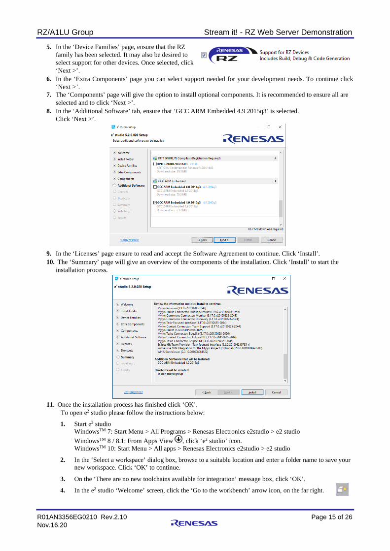
5. In the ‘Device Families’ page, ensure that the RZ family has been selected. It may also be desired to select support for other devices. Once selected, click ‘Next >’.
6. In the ‘Extra Components’ page you can select support needed for your development needs. To continue click ‘Next >’.
7. The ‘Components’ page will give the option to install optional components. It is recommended to ensure all are selected and to click ‘Next >’.
8. In the ‘Additional Software’ tab, ensure that ‘GCC ARM Embedded 4.9 2015q3’ is selected. Click ‘Next >’.
9. In the ‘Licenses’ page ensure to read and accept the Software Agreement to continue. Click ‘Install’. 10. The ‘Summary’ page will give an overview of the components of the installation. Click ‘Install’ to start the
installation process.
11. Once the installation process has finished click ‘OK’. To open e2 studio please follow the instructions below:
1. Start e2 studio WindowsTM 7: Start Menu > All Programs > Renesas Electronics e2studio > e2 studio WindowsTM 8 / 8.1: From Apps View , click ‘e2 studio’ icon. WindowsTM 10: Start Menu > All apps > Renesas Electronics e2studio > e2 studio
2. In the ‘Select a workspace’ dialog box, browse to a suitable location and enter a folder name to save your new workspace. Click ‘OK’ to continue.
3. On the ‘There are no new toolchains available for integration’ message box, click ‘OK’.
4. In the e2 studio ‘Welcome’ screen, click the ‘Go to the workbench’ arrow icon, on the far right.

RZ/A1LU Group Stream it! - RZ Web Server Demonstration
R01AN3356EG0210 Rev.2.10 Page 16 of 26 Nov.16.20
5. Code Generator Registration window will pop up to register code generator. Click ‘OK’.
6. Once registered, another pop-up window will ask you to restart e2 studio. Click ‘OK’. e2 studio will restart.
3.3 e2 studio Update To update e2 studio both RZ support and the GNU ARM Embedded v4.9.3 compiler are to be installed. This is recommended to be done on e2 studio version 4.3 or later.
To install the ‘RZ support’ please follow the below instructions:
1. The RZ support can be installed through Renesas’ tool support link. This can be achieved through
Help -> Install New Software…
Followed by inserting the following link in the ‘Work with’ box.
http://tool-support.renesas.com/e2studio/e2studio5
2. Select the ‘Renesas RZ Family Support’ and click ‘Next >’.
3. Installation details will then be shown. Click ‘Next >’.
4. Read the ‘License text’ and select ‘I accept the terms of the license agreement’ to continue.
A pop-up window will then ask you to restart e2 studio. Click ‘Yes’.
5. Once restarted the installation process is complete.

RZ/A1LU Group Stream it! - RZ Web Server Demonstration
R01AN3356EG0210 Rev.2.10 Page 17 of 26 Nov.16.20
3.4 Importing the Project into e2 studio 1. Start e2 studio (skip this step if already open):
WindowsTM 7: Start Menu > All Programs > Renesas Electronics e2studio > e2 studio WindowsTM 8 / 8.1: From Apps View , click ‘e2 studio’ icon. WindowsTM 10: Start Menu > All apps > Renesas Electronics e2studio > e2 studio
2. Select your desired e2 studio workspace (C:\Temp in this case) and press ‘OK’.
3. On the Welcome splash screen press ‘Go to the e2 studio workbench’.
4. Right-click in the Project Explorer window, and select ‘Import…’.
5. Under ‘Select an import source’, select 'General > Existing Projects into Workspace', and click ‘Next’.

RZ/A1LU Group Stream it! - RZ Web Server Demonstration
R01AN3356EG0210 Rev.2.10 Page 18 of 26 Nov.16.20
6. Select archive file then click the ‘Browse’ button, and locate the zipped project location
7. Ensure the ‘Copy projects into workspace’ option is ticked and then click ‘Finish’.
8. The opened project should look like the image (above).

RZ/A1LU Group Stream it! - RZ Web Server Demonstration
R01AN3356EG0210 Rev.2.10 Page 19 of 26 Nov.16.20
3.5 Compiling the Software The software compilation can be started using any 1 of 3 methods:
• Push the Build button ( ).
• Use the Project | Build-All option in the menu.
• Use the Build-All keyboard shortcut CTRL+B.
3.6 Running the Software There are two different methods for running the project; from a batch file, or from e2 studio. Firstly, the board needs to be connected up:
• Connect your JLink Lite debugger to the connector JTAG on the Stream it! - RZ board
• Connect the USB cable between your PC and the JLink debugger
• Connect a USB cable between your PC and the Stream it! - RZ board
• Apply power to the USB port (CN10 - next to the SD card socket) or press the reset switch (located above the ‘A’ of the Renesas logo on the board and labelled ‘RESET’) to reset the device
3.6.1. Running From the Batch File
This method uses the Stream it! - RZ Boot Loader to run the application. It may be necessary to obtain this loader application to use this method. Copy the ‘StreamIt2_WebServer.bin’ file into ‘StreamIt2_QSPI_Loader\scripts’ and rename the bin file to ‘StreamIt2_User_App.bin’. Run the batch file ‘Program_QSPI_Loader_Application.bat’ that is in the project ‘scripts’ folder.
A window should pop up for the few seconds that it takes for the binary file to be copied to the flash memory on the Stream it! - RZ board.
Once the SPI flash has been reprogrammed the new code will be executed on device reset. The boot loader will determine if the user code needs to be relocated into RAM or executed in place from SPI as this is specified in the linker file. Details on the boot loader application are in the ‘QSPI Flash Boot Loader’ document which can be found on the product website.

RZ/A1LU Group Stream it! - RZ Web Server Demonstration
R01AN3356EG0210 Rev.2.10 Page 20 of 26 Nov.16.20
Unless the application is overwritten with another one, this application will now run automatically each time the board is powered on.
3.6.2. Running From e2 studio
The provided e2 studio workspace has two build configurations - ‘HardwareDebug’ and ‘Release’.
Hardware Debug - This default build mode has all optimisation turned off, and provides full debug information. This is the best configuration to use whilst developing code as C code execution will be linear.
Release - This build mode has optimisation turned on, and provides little debug information. The C code execution may appear to be out of order, due to the way compiler optimises the code. This build configuration is intended for final ROM-programmable code.
1. Press the ‘Debug’ button ( ) to open the ‘Debug Configurations’ dialog.
Select the configuration you wish to use (HardwareDebug in this case). Note that if the application (.x) file is not available or has errors, then the ‘Debug’ button on the bottom right will be disabled.
2. Press the ‘Debug’ button on the bottom right to start the download process.
3. Once program download has complete the code execution will be at the entry point of your application which should look similar to the code segment above.
4. Pressing the resume button ( ) will continue code execution. The code should stop again at the start of your main function. Pressing resume one more time will execute the rest of your code.
The code should now be running on your target device in RAM.

RZ/A1LU Group Stream it! - RZ Web Server Demonstration
R01AN3356EG0210 Rev.2.10 Page 21 of 26 Nov.16.20
4. Project Details This section details the sample project layout, components used and execution cycle.
4.1 Project Layout The project layout as shown in e2 studio is as follows:-
The following folders contain useful or user modifiable contents:
• doc Text file detailing simple download instructions and links to documentation • src Source code for project. All user modifiable code is located in this sub folder
File main.c contains the start of the user level application (main function). The debugger is configured to stop execution at the start of the main function.
4.2 Runtime Environment The following resources are used in the application:
Resource Device Function/Description Source File INTC_ID_ADI A2D
converter Interrupt for 12-bit A/D converter used for ADC Value on AJAX Demo pages (1 & 2)
src\renesas\peripherals\internal\r_adc.c
INTC_ID_RXI3 UART Ch3
Receive Interrupt used to provide serial console
src\renesas\application\cli.c
INTC_ID_OSTM0TINT OS Timer Ch0
Provides system tick interrupt used by FreeRTOS
src\oryx\demo\freertos\freertos_tick_config.c
INTC_ID_ETHERI Ethernet Ch0
Wired Ethernet interrupt handler, used by cyclone_tcp driver
src\oryx\clyclone_tcp\drivers\rza1_eth.c
I2C Channel 1 I2C Bus Interface
Used to communicate with the BMA250 triaxial acceleration sensor
src\renesas\peripherals\internal\riic_userdef.c src\renesas\peripherals\internal\r_riic_api.c src\renesas\peripherals\internal\r_riic_streamit.c

RZ/A1LU Group Stream it! - RZ Web Server Demonstration
R01AN3356EG0210 Rev.2.10 Page 22 of 26 Nov.16.20
4.3 Startup Sequence The following table gives a brief overview of the boot process for the device (executed before first call to main()):
File Action Details src\renesas\compiler\asm\start.s Program start Creates initial vector table, calls reset vector src\renesas\compiler\reset_handler.s Reset code Performs system reset, initialises arm stacks,
memory manager, etc. Calls peripheral_init_basic to initialise board Final action is to call resetprg() in resetprg.c
src\renesas\compiler\init\resetprg.c ‘C’ level code initialisation
Initialises any library code, enables irqs and fiqs Calls ‘C’ level main()
src\main.c Start application
Initialises rest of in-use board peripherals Creates pre-kernel tasks Starts the kernel
The following FreeRTOS tasks are created:
Priority
Name Short Description
1 Cli Command line parser task 1 Connection Task Manages network setup and configuration, then sleeps 1 Read Data Task Periodically reads the BMA250 sensor, potentiometer and updates the
relevant global data 1 Blink Performs LED control for USER LED 1 TCP/IP Stack (Tick) Task Manages periodic TCP/IP operations 2 TCP/IP Stack (RX) Task Manages incoming data packets 1 HTTP Connection Task APP_HTTP_MAX_CONNECTIONS tasks, 1 task per potential connection (see
below)
1 HTTP Listener Task Manages new connections blocking too many simultaneous connections 4 Tmr Svc FreeRTOS system timer handler 0 IDLE FreeRTOS idle activity handler
Source code ref. (APP_HTTP_MAX_CONNECTIONS \StreamIt2_WebServer\src\renesas\configuration\config.h line 68).

RZ/A1LU Group Stream it! - RZ Web Server Demonstration
R01AN3356EG0210 Rev.2.10 Page 23 of 26 Nov.16.20
The following diagram shows the task startup sequence and dependencies:
Figure 6 Task creation workflow
New ThreadCli Task
cli_init()
Main()
Function call
New ThreadConnection Task
Star
tup
Sequ
ence
New ThreadRead Data Task
New ThreadBlink
New ThreadTCP/IP Stack (Tick)
New ThreadTCP/IP Stack (RX)
New ThreadHTTP Connection
New ThreadHTTP Listener
osStartKernel()
Pre-osStartKernel Post-osStartKernel

RZ/A1LU Group Stream it! - RZ Web Server Demonstration
R01AN3356EG0210 Rev.2.10 Page 24 of 26 Nov.16.20
5. High Level Overview of Source Tree Key Components The application sample code is stored in the ‘src’ (sources) folder, the following provides a brief introduction into the layout of this folder. The src (sources) folder:
The layout of the src (sources) folder is as follows: Name Overview renesas\application Stores all the application specific files. renesas\compiler Stores any files specific to the startup procedure of the microcontroller
The GNU linker (.ld) file is located in this folder renesas\peripherals Stores the peripheral drivers required for this board.
Internal folder stores the microcontroller peripheral drivers (e.g. adc, jcu, etc.) External folder stores the non-microcontroller peripheral drivers (e.g. sensors, camera, etc.)
renesas\configuration Application configuration freertos Stores the FreeRTOS V9.0.0 embedded operating system (OS) source code.
The OS configuration is controlled by the local file \StreamIt2_WebServer\src\oryx\demo\freertosconfig.h
oryx Stores the Oryx Embedded HTTP server and demo code. The website (index.html, css and js scripts etc.) located in the subfolder \StreamIt2_WebServer\src\oryx\resources\www

RZ/A1LU Group Stream it! - RZ Web Server Demonstration
R01AN3356EG0210 Rev.2.10 Page 25 of 26 Nov.16.20
6. Further Reading Technical Support
For details on how to use e2 studio, refer to the help file by opening e2 studio, then selecting Help > Help Contents from the menu bar.
For information about the RZA1L series microcontrollers refer to the RZA1L Group Hardware Manual.
Technical Contact Details
Please refer to the contact details listed in section 5 of the Stream it! - RZ “Quick Start Guide” (r12qs0013eg0100-rza1lu.pdf).
General information on Renesas microcontrollers can be found on the Renesas website at: https://www.renesas.com/
Inquiries:
https://www.renesas.com/contact/
This product’s homepage, where additional documentation and source code can be found, is located at: https://www.renesas.com/en-eu/solutions/key-technology/human-interface/rz-stream-it.html

RZ/A1LU Group Stream it! - RZ Web Server Demonstration
R01AN3356EG0210 Rev.2.10 Page 26 of 26 Nov.16.20
Revision History
Rev. Date Description Page Summary
1.00 20 Mar 2017 All Original release 2.00 25 Jan 2018 -- Code change. Accelerometer ID. 2.10 16 Nov 2020 All Application Note Software Update

General Precautions in the Handling of Microprocessing Unit and Microcontroller Unit Products The following usage notes are applicable to all Microprocessing unit and Microcontroller unit products from Renesas. For detailed usage notes on the products covered by this document, refer to the relevant sections of the document as well as any technical updates that have been issued for the products.
1. Precaution against Electrostatic Discharge (ESD)
A strong electrical field, when exposed to a CMOS device, can cause destruction of the gate oxide and ultimately degrade the device operation. Steps
must be taken to stop the generation of static electricity as much as possible, and quickly dissipate it when it occurs. Environmental control must be
adequate. When it is dry, a humidifier should be used. This is recommended to avoid using insulators that can easily build up static electricity.
Semiconductor devices must be stored and transported in an anti-static container, static shielding bag or conductive material. All test and
measurement tools including work benches and floors must be grounded. The operator must also be grounded using a wrist strap. Semiconductor
devices must not be touched with bare hands. Similar precautions must be taken for printed circuit boards with mounted semiconductor devices. 2. Processing at power-on
The state of the product is undefined at the time when power is supplied. The states of internal circuits in the LSI are indeterminate and the states of
register settings and pins are undefined at the time when power is supplied. In a finished product where the reset signal is applied to the external reset
pin, the states of pins are not guaranteed from the time when power is supplied until the reset process is completed. In a similar way, the states of pins
in a product that is reset by an on-chip power-on reset function are not guaranteed from the time when power is supplied until the power reaches the
level at which resetting is specified. 3. Input of signal during power-off state
Do not input signals or an I/O pull-up power supply while the device is powered off. The current injection that results from input of such a signal or I/O
pull-up power supply may cause malfunction and the abnormal current that passes in the device at this time may cause degradation of internal
elements. Follow the guideline for input signal during power-off state as described in your product documentation. 4. Handling of unused pins
Handle unused pins in accordance with the directions given under handling of unused pins in the manual. The input pins of CMOS products are
generally in the high-impedance state. In operation with an unused pin in the open-circuit state, extra electromagnetic noise is induced in the vicinity of
the LSI, an associated shoot-through current flows internally, and malfunctions occur due to the false recognition of the pin state as an input signal
become possible. 5. Clock signals
After applying a reset, only release the reset line after the operating clock signal becomes stable. When switching the clock signal during program
execution, wait until the target clock signal is stabilized. When the clock signal is generated with an external resonator or from an external oscillator
during a reset, ensure that the reset line is only released after full stabilization of the clock signal. Additionally, when switching to a clock signal
produced with an external resonator or by an external oscillator while program execution is in progress, wait until the target clock signal is stable. 6. Voltage application waveform at input pin
Waveform distortion due to input noise or a reflected wave may cause malfunction. If the input of the CMOS device stays in the area between VIL
(Max.) and VIH (Min.) due to noise, for example, the device may malfunction. Take care to prevent chattering noise from entering the device when the
input level is fixed, and also in the transition period when the input level passes through the area between VIL (Max.) and VIH (Min.). 7. Prohibition of access to reserved addresses
Access to reserved addresses is prohibited. The reserved addresses are provided for possible future expansion of functions. Do not access these
addresses as the correct operation of the LSI is not guaranteed. 8. Differences between products
Before changing from one product to another, for example to a product with a different part number, confirm that the change will not lead to problems.
The characteristics of a microprocessing unit or microcontroller unit products in the same group but having a different part number might differ in terms
of internal memory capacity, layout pattern, and other factors, which can affect the ranges of electrical characteristics, such as characteristic values,
operating margins, immunity to noise, and amount of radiated noise. When changing to a product with a different part number, implement a system-
evaluation test for the given product.

© 2020 Renesas Electronics Corporation. All rights reserved.
Notice 1. Descriptions of circuits, software and other related information in this document are provided only to illustrate the operation of semiconductor products
and application examples. You are fully responsible for the incorporation or any other use of the circuits, software, and information in the design of your product or system. Renesas Electronics disclaims any and all liability for any losses and damages incurred by you or third parties arising from the use of these circuits, software, or information.
2. Renesas Electronics hereby expressly disclaims any warranties against and liability for infringement or any other claims involving patents, copyrights, or other intellectual property rights of third parties, by or arising from the use of Renesas Electronics products or technical information described in this document, including but not limited to, the product data, drawings, charts, programs, algorithms, and application examples.
3. No license, express, implied or otherwise, is granted hereby under any patents, copyrights or other intellectual property rights of Renesas Electronics or others.
4. You shall not alter, modify, copy, or reverse engineer any Renesas Electronics product, whether in whole or in part. Renesas Electronics disclaims any and all liability for any losses or damages incurred by you or third parties arising from such alteration, modification, copying or reverse engineering.
5. Renesas Electronics products are classified according to the following two quality grades: “Standard” and “High Quality”. The intended applications for each Renesas Electronics product depends on the product’s quality grade, as indicated below. "Standard": Computers; office equipment; communications equipment; test and measurement equipment; audio and visual equipment; home
electronic appliances; machine tools; personal electronic equipment; industrial robots; etc. "High Quality": Transportation equipment (automobiles, trains, ships, etc.); traffic control (traffic lights); large-scale communication equipment; key
financial terminal systems; safety control equipment; etc. Unless expressly designated as a high reliability product or a product for harsh environments in a Renesas Electronics data sheet or other Renesas Electronics document, Renesas Electronics products are not intended or authorized for use in products or systems that may pose a direct threat to human life or bodily injury (artificial life support devices or systems; surgical implantations; etc.), or may cause serious property damage (space system; undersea repeaters; nuclear power control systems; aircraft control systems; key plant systems; military equipment; etc.). Renesas Electronics disclaims any and all liability for any damages or losses incurred by you or any third parties arising from the use of any Renesas Electronics product that is inconsistent with any Renesas Electronics data sheet, user’s manual or other Renesas Electronics document.
6. When using Renesas Electronics products, refer to the latest product information (data sheets, user’s manuals, application notes, “General Notes for Handling and Using Semiconductor Devices” in the reliability handbook, etc.), and ensure that usage conditions are within the ranges specified by Renesas Electronics with respect to maximum ratings, operating power supply voltage range, heat dissipation characteristics, installation, etc. Renesas Electronics disclaims any and all liability for any malfunctions, failure or accident arising out of the use of Renesas Electronics products outside of such specified ranges.
7. Although Renesas Electronics endeavors to improve the quality and reliability of Renesas Electronics products, semiconductor products have specific characteristics, such as the occurrence of failure at a certain rate and malfunctions under certain use conditions. Unless designated as a high reliability product or a product for harsh environments in a Renesas Electronics data sheet or other Renesas Electronics document, Renesas Electronics products are not subject to radiation resistance design. You are responsible for implementing safety measures to guard against the possibility of bodily injury, injury or damage caused by fire, and/or danger to the public in the event of a failure or malfunction of Renesas Electronics products, such as safety design for hardware and software, including but not limited to redundancy, fire control and malfunction prevention, appropriate treatment for aging degradation or any other appropriate measures. Because the evaluation of microcomputer software alone is very difficult and impractical, you are responsible for evaluating the safety of the final products or systems manufactured by you.
8. Please contact a Renesas Electronics sales office for details as to environmental matters such as the environmental compatibility of each Renesas Electronics product. You are responsible for carefully and sufficiently investigating applicable laws and regulations that regulate the inclusion or use of controlled substances, including without limitation, the EU RoHS Directive, and using Renesas Electronics products in compliance with all these applicable laws and regulations. Renesas Electronics disclaims any and all liability for damages or losses occurring as a result of your noncompliance with applicable laws and regulations.
9. Renesas Electronics products and technologies shall not be used for or incorporated into any products or systems whose manufacture, use, or sale is prohibited under any applicable domestic or foreign laws or regulations. You shall comply with any applicable export control laws and regulations promulgated and administered by the governments of any countries asserting jurisdiction over the parties or transactions.
10. It is the responsibility of the buyer or distributor of Renesas Electronics products, or any other party who distributes, disposes of, or otherwise sells or transfers the product to a third party, to notify such third party in advance of the contents and conditions set forth in this document.
11. This document shall not be reprinted, reproduced or duplicated in any form, in whole or in part, without prior written consent of Renesas Electronics. 12. Please contact a Renesas Electronics sales office if you have any questions regarding the information contained in this document or Renesas
Electronics products.
(Note1) “Renesas Electronics” as used in this document means Renesas Electronics Corporation and also includes its directly or indirectly controlled subsidiaries.
(Note2) “Renesas Electronics product(s)” means any product developed or manufactured by or for Renesas Electronics.
(Rev.4.0-1 November 2017)
Corporate Headquarters Contact information TOYOSU FORESIA, 3-2-24 Toyosu, Koto-ku, Tokyo 135-0061, Japan www.renesas.com
For further information on a product, technology, the most up-to-date version of a document, or your nearest sales office, please visit: www.renesas.com/contact/.
Trademarks Renesas and the Renesas logo are trademarks of Renesas Electronics Corporation. All trademarks and registered trademarks are the property of their respective owners.