
RZ/T1 Group Application Note Tool Application Guide ...
53
R01AN3860EJ0110 Rev.1.10 Page 1 of 50 Apr. 11, 2018 RZ/T1 Group Guide for Applying the Code Generation Tool to the Sample Program APPLICATION NOTE Introduction This application note describes the process of incorporating a control program for peripheral modules of the microcontroller (device driver program) in the sample program of the RZ/T1 Group Initial Settings. The code for the control program is generated by the automatic generation tool for I/O drivers (hereinafter called the Code Generation Tool). The resulting sample program enables periodic counter operation of the compare match timer (CMT) that produces compare-match interrupts which are used to switch an LED on and off. Target Devices RZ/T1 Group When applying the program covered in this application note to another microcontroller, modify the program to suit the specifications of the target microcontroller and extensively evaluate the program after modification. R01AN3860EJ0110 Rev.1.10 Apr. 11, 2018 Introduction
Transcript of RZ/T1 Group Application Note Tool Application Guide ...

R01AN3860EJ0110 Rev.1.10 Page 1 of 50Apr. 11, 2018
RZ/T1 GroupGuide for Applying the Code Generation Tool to the Sample Program
APPLICATION NOTE
IntroductionThis application note describes the process of incorporating a control program for peripheral modules of the microcontroller (device driver program) in the sample program of the RZ/T1 Group Initial Settings. The code for the control program is generated by the automatic generation tool for I/O drivers (hereinafter called the Code Generation Tool).
The resulting sample program enables periodic counter operation of the compare match timer (CMT) that produces compare-match interrupts which are used to switch an LED on and off.
Target DevicesRZ/T1 Group
When applying the program covered in this application note to another microcontroller, modify the program to suit the specifications of the target microcontroller and extensively evaluate the program after modification.
R01AN3860EJ0110Rev.1.10
Apr. 11, 2018
Introduction
1. Specifications.................................................................................................................................... 3
2. Operating Environment ..................................................................................................................... 4
3. Related Application Notes................................................................................................................. 5
4. Peripheral Functions ......................................................................................................................... 6
5. Hardware .......................................................................................................................................... 75.1 Hardware Configuration Examples ......................................................................................... 75.2 Pins......................................................................................................................................... 8
6. Software............................................................................................................................................ 96.1 Operation Overview................................................................................................................ 9
6.1.1 Project Settings ............................................................................................................ 11
6.1.2 Preparation ................................................................................................................... 136.1.3 Exception Processing Vector Table.............................................................................. 13
6.2 Interrupts............................................................................................................................... 14
6.3 Procedure for Incorporating Code from the Code Generation Tool...................................... 156.3.1 Generating Code with the Code Generation Tool ........................................................ 156.3.2 Incorporation in the Sample Program of RZ/T1 Group Initial Settings ......................... 31
6.4 Fixed-Width Integer Types.................................................................................................... 436.5 Function................................................................................................................................ 436.6 Flowchart .............................................................................................................................. 44
6.6.1 Loader Program Processing......................................................................................... 446.6.2 Processing by the Application Program Created by the Code Generation Tool........... 456.6.3 Common main Processing ........................................................................................... 46
6.6.4 Interrupt Processing by the Timer Selected by the User (CMT0)................................. 46
7. Sample Program............................................................................................................................. 47
8. Related Documents ........................................................................................................................ 48
9. Usage Note ..................................................................................................................................... 49
Table of Contents

R01AN3860EJ0110 Rev.1.10 Page 3 of 50Apr. 11, 2018
RZ/T1 Group Guide for Applying the Code Generation Tool to the Sample Program
1. SpecificationsTable 1.1 lists the peripheral functions used and their applications and Figure 1.1 shows the operating environment.
Table 1.1 Peripheral Functions and Their Applications
Peripheral Module Application
Clock generation circuit (CPG) Provides the CPU clock and low-speed on-chip oscillator
Interrupt Controller (ICUA) Processing the compare-match interrupt (CMI0)
Compare match timer (CMT) Periodic counter operation and tests for matches by the compare match timer
Bus state controller (BSC) Connection of NOR flash memory to the CS0 and CS1 spaces and SDRAM to the CS2 and CS3 spaces.
SPI multi I/O bus controller (SPIBSC) Used to connect the serial flash memory to SPI multi I/O space
Error control module (ECM) Initial setting of the ERROROUT# pin
General I/O port Control of pin output to turn the LED on and off
Note 1. Indicates the device that the user needs to prepare.
Figure 1.1 Operating Environment
Host computer*1
CAN
USB(Host/Func)
LAN EtherCAT
R7S910018
PMOD1
DSMIF
PMOD2
JTAG
Microphoneheadphone
SerialRZ/T1 evaluation boardRTK7910018C00000BE
DC5V outputAC adaptor
(Included accessory)
ICE*1

R01AN3860EJ0110 Rev.1.10 Page 4 of 50Apr. 11, 2018
RZ/T1 Group Guide for Applying the Code Generation Tool to the Sample Program
2. Operating EnvironmentThe sample program covered in this application note runs in the environment below.
Table 2.1 Operating Environment
Item Description
Microcomputer RZ/T1 Group
Operating frequency CPUCLK = 450 MHz
Operating voltage 3.3 V
Integrated development environment (any of those listed)
From IAR Systems:Embedded Workbench for ARM Version 7.80.2From ARM:DS-5TM 5.25From Renesas:e2studio 5.2.0
Tool for generating code From Renesas:AP4 1.07
Note: The e2studio includes a plug-in that has equivalent functionality for generating code to that of AP4 1.04.
Operating mode SPI boot mode16-bit bus boot mode
Board used RZ/T1 evaluation board(RTK7910018C00000BE)
Device used(Functions used on the board)
• NOR flash memory (for connection to the CS0 and CS1 spaces)Manufacturer: Macronix International Co., Ltd. Model: MX29GL512FLT2I-10Q
• SDRAM (for connection to the CS2 and CS3 spaces)Manufacturer: Integrated Silicon Solution Inc.Model: IS42S16320D-7TL
• Serial flash memoryManufacturer: Macronix International Co., Ltd.Model: MX25L51245G

R01AN3860EJ0110 Rev.1.10 Page 5 of 50Apr. 11, 2018
RZ/T1 Group Guide for Applying the Code Generation Tool to the Sample Program
3. Related Application NotesOther application notes that are related to this one are listed below. Please refer to them, too.
• RZ/T1 Group Initial Settings (R01AN2554EJ)• RZ/T1 Group Compare Match Timer (CMT) (R01AN2555EJ)

R01AN3860EJ0110 Rev.1.10 Page 6 of 50Apr. 11, 2018
RZ/T1 Group Guide for Applying the Code Generation Tool to the Sample Program
4. Peripheral FunctionsSee the RZ/T1 Group User's Manual: Hardware for basic descriptions of operating modes and the clock generation circuit (CPG), compare match timer (CMT), interrupt controller (ICUA), bus state controller (BSC), SPI multi I/O bus controller (SPIBSC), error control module (ECM), reset system, and general I/O ports.

R01AN3860EJ0110 Rev.1.10 Page 7 of 50Apr. 11, 2018
RZ/T1 Group Guide for Applying the Code Generation Tool to the Sample Program
5. Hardware
5.1 Hardware Configuration ExamplesFigure 5.1 shows an example of the hardware configuration for this application.
Figure 5.1 Example of the Hardware Configuration
ICUA(Interrupt control unit A) Cortex-R4F Low power
consumption
RZ/T1
CMT Ch0 I/O port
LED10
Write protection for registers
PM7

R01AN3860EJ0110 Rev.1.10 Page 8 of 50Apr. 11, 2018
RZ/T1 Group Guide for Applying the Code Generation Tool to the Sample Program
5.2 PinsTable 5.1 lists pins to be used and their functions.
Note: The mark "#" indicates negative logic (i.e. active low).Note 1. The function for this pin is to be set by the Code Generation Tool for that purpose.
Table 5.1 Pins and Functions
Pin Name Input/Output Function
A1 to A25*1 Output Address signal output for NOR flash memory and SDRAM
D0 to D15*1 Input/Output Data signal input and output for NOR flash memory and SDRAM
CS0#*1 Output Device selection signal output to NOR flash memory in the CS0 space
CS1#*1 Output Device selection signal output to NOR flash memory in the CS1 space
CS2#*1 Output Device selection signal output to SDRAM in the CS2 space
CS3#*1 Output Device selection signal output to SDRAM in the CS3 space
RAS#*1 Output RAS# control signal output to SDRAM
CAS# *1 Output CAS# control signal output to SDRAM
RD/WR#*1 Output Read control signal or write control signal output to SDRAM
CKE*1 Output CK enabling control signal output to SDRAM
RD#*1 Output Strobe signal output indicating reading
BS# Output Not used in this sample program.
WE0#/DQMLL*1 Output Write strobe signal output for D15 to D8
WE1#/DQMLU*1 Output Write strobe signal output for D7 to D0
SPBSSL*1 Output Slave selection
SPBCLK*1 Output Clock output
SPBMO/SPBIO0*1 Input/Output Master output data: data 0
SPBMI/SPBIO1*1 Input/Output Master input data: data 1
SPBIO2*1 Input/Output Data 2
SPBIO3*1 Input/Output Data 3
MD0 Input Boot mode selection:MD0 = "L", MD1 = "L", MD2 = "L" (SPI boot mode)MD0 = "L", MD1 = "H", MD2 = "L" (16-bit bus boot mode)MD1 Input
MD2 Input
PM7*1 Output Lighting and darkening LED10

R01AN3860EJ0110 Rev.1.10 Page 9 of 50Apr. 11, 2018
RZ/T1 Group Guide for Applying the Code Generation Tool to the Sample Program
6. Software
6.1 Operation OverviewThis sample program is based on the sample program of the RZ/T1 Group Initial Settings. The loader program of the sample program of of the Initial Settings is used as it is for the loader program (loader) section. The user application program (user application) incorporates the code generated by the Code Generation Tool with the common main code. The actual process of incorporation will be described later.
See Application Note: RZ/T1 Group Initial Settings for more details on the operation of the sample program of the RZ/T1 Group Initial Settings.
Figure 6.1 shows the configuration outline of the sample program produced in this application note.
• The user application section in the sample program of the Initial Settings should be replaced with the user application section generated with the Code Generation Tool.
• Incorporating code from the Code Generation Tool as in this process can, for example, allow more efficient program development in the case of changes to the set-up of peripheral functions.
• A common main function was generated for this sample program to replace that in the sample program of the Initial Settings.
Figure 6.1 Configuration of This Sample Program in Outline
Sample program of Initial Settings
Code created by the tool
Code Generation Tool
Common main
Loader section
User application section
This part of the sample program of the Initial Settings is used as it is.
Added for this sample program

R01AN3860EJ0110 Rev.1.10 Page 10 of 50Apr. 11, 2018
RZ/T1 Group Guide for Applying the Code Generation Tool to the Sample Program
Figure 6.2 shows the operation of the loader and user application initial sections in outline.
After the device is booted up, the loader sets up the stack among other things, copies the user application program, and causes execution to branch to the address where the user application program starts.
As you see in the figure below, both the loader from the sample program of the Initial Settings and the user application code generated through automatic code generation make settings for the clock and bus controllers. Therefore, in this program, conflicts between the settings have been avoided by disabling (commenting out) the settings for the clock and bus controllers in the loader.
The code generated by code generation for the user application sets up the interrupt controller, the clock, the buses and other peripheral modules. Settings in this part of the code are made to suit the operating mode in use (in this case, SPI boot, 16-bit bus boot).
Settings to start cyclic counter operation of the compare match timer (CMT) and for switching the LED on and off in response to compare match A interrupts are made in the common main function, which is independent of the operating mode.
This process of incorporation demonstrates how users are able to use code produced by setting in the Code Generation Tool as desired with the loader section of the sample program of the Initial Settings.
Note 1. Settings for the clock oscillator and bus controllers in the loader program are commented out to avoid conflict with the settings from the Code Generation Tool.However, if you would like to speed up copying to the ATCM, etc.in the loader program, you can move the code for settings produced by the code generator to the loader program.
Note 2. The compare match timer (CMT) is used to produce periods of waiting in setting up the error control module (ECM), and the CMT is reinitialized after that process.To avoid conflict with code from the Code Generation Tool, setting the ECM up was transferred from the main process of the sample program of the Initial Settings to the loader program for this application. See Application Note: RZ/T1 Group Initial Settings for more details on setting the ECM up.
Figure 6.2 Outline of Operations after Booting Up the Device
Loader section in the BTCM area
Initialization of stack, VFP, variables, etc.
Copying of the user application program and variables
Code Generation Tool Branching to the application program
Bus-controller settings (BSC, SPIBSC)Set by the Code Generation Tool following deletion
from the program of the Initial Settings.*1
Clock oscillator settings (450 MHz)Set by the Code Generation Tool following deletion
from the program of the Initial Settings.*1
ECM settings*2
Taken from main for the Initial Settings
User application section in the ATCM area
16-bit bus boot (NOR) versionCreated by the Code Generation Tool
SPI-boot (serial) version Created by the Code Generation Tool
Code Generation ToolStarting the application program
Interrupt and pin settings
Settings by code from the Code Generation ToolSettings of clock oscillator,
bus state controller, SPI multi I/O bus controller,
compare match timer and other user settings
Common main
Branch to common main
Start of loader program
R01AN3860EJ0110 Rev.1.10 Page 11 of 50Apr. 11, 2018
RZ/T1 Group Guide for Applying the Code Generation Tool to the Sample Program
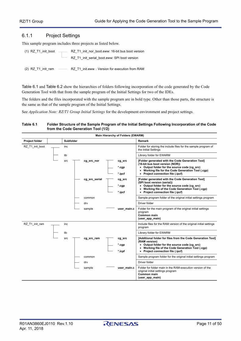
6.1.1 Project SettingsThis sample program includes three projects as listed below.
Table 6.1 and Table 6.2 show the hierarchies of folders following incorporation of the code generated by the Code Generation Tool with that from the sample program of the Initial Settings for two of the IDEs.
The folders and the files incorporated with the sample program are in bold type. Other than those parts, the structure is the same as that of the sample program of the Initial Settings.
See Application Note: RZ/T1 Group Initial Settings for the development environment and project settings.
Table 6.1 Folder Structure of the Sample Program of the Initial Settings Following Incorporation of the Code from the Code Generation Tool (1/2)
Main Hierarchy of Folders (EWARM)
Project folder Subfolder Remark
RZ_T1_init_boot inc Folder for storing the include files for the sample program of the Initial Settings
lib Library folder for EWARM
src cg_src_nor cg_src
*.cgp
*.ipcf
[Folder generated with the Code Generation Tool](16-bit bus boot version (NOR))
• Output folder for the source code (cg_src)• Working file for the Code Generation Tool (.cgp)• Project connection file (.ipcf)
cg_src_serial cg_src
*.cgp
*.ipcf
[Folder generated with the Code Generation Tool](SPI boot version (serial))
• Output folder for the source code (cg_src)• Working file of the Code Generation Tool (.cgp)• Project connection file (.ipcf)
common Sample program folder of the original initial settings program
drv Driver folder
sample user_main.c Folder for the main program of the original initial settings programCommon main(user_app_main)
RZ_T1_init_ram inc Include files for the RAM version of the original initial settings program
lib Library folder for EWARM
src cg_src_ram cg_src
*.cgp
*.icpf
[Additional folder for files from the Code Generation Tool](RAM version)
• Output folder for the source code (cg_src)• Working file of the Code Generation Tool (.cgp)• Project connection file (.ipcf)
common Sample program folder for the original initial settings program
drv Driver folder
sample user_main.c Folder for folder main in the RAM-execution version of the original initial settings programCommon main(user_app_main)
(1) RZ_T1_init_boot
(2) RZ_T1_init_ram
RZ_T1_init_nor_boot.eww: 16-bit bus boot version
RZ_T1_init_serial_boot.eww: SPI boot version
RZ_T1_init.eww:Version for execution from RAM

R01AN3860EJ0110 Rev.1.10 Page 12 of 50Apr. 11, 2018
RZ/T1 Group Guide for Applying the Code Generation Tool to the Sample Program
Note 1. When incorporating code generated with the Code Generation Tool in the e2studio environment, place iodefine.h from the inc folders of each of the projects immediately below the project folder.
Table 6.2 Folder Structure of the Sample Program of the Initial Settings Following Incorporation of the Code from the Code Generation Tool (2/2)
Main Hierarchy of Folders (e2studio)
Project folder Subfolder Remark
RZ_T_nor_sample .setting CodeGenerator [Folder generated with the Code Generation Tool](16-bit bus boot version (NOR))
• Working file for the Code Generation Tool (.cgp)
inc Folder for storing the include files for the sample program of the Initial Settings
src cg_src [Folder generated with the Code Generation Tool](16-bit bus boot version (NOR))
• Output folder for the source code (cg_src)
common Sample program folder of the original initial settings program
drv Driver folder
sample user_main.c Folder for the main program of the original initial settings programCommon main(user_app_main)
iodefine.h*1 iodefine for the e2studio, transferred from the inc folder
RZ_T_sflash_sample .setting CodeGenerator [Folder generated with the Code Generation Tool](SPI boot version (serial))
• Working file of the Code Generation Tool (.cgp)
inc Folder for storing the include files for the sample program of the Initial Settings
src cg_src [Folder generated with the Code Generation Tool](SPI boot version (serial))
• Output folder for the source code (cg_src)
common Sample program folder of the original initial settings program
drv Driver folder
sample user_main.c Folder for the main program of the original initial settings programCommon main(user_app_main)
iodefine.h*1 iodefine for the e2studio, transferred from the inc folder
RZ_T_ram_sample .setting CodeGenerator [Folder generated with the Code Generation Tool] (RAM version)
• Working file of the Code Generation Tool (.cgp)
inc Include files for the RAM version of the original initial settings program
src cg_src [Folder generated with the Code Generation Tool](RAM version)
• Output folder for the source code (cg_src)
common Sample program folder of the original initial settings program
drv Driver folder
sample user_main.c Folder for the main program of the RAM version of the original initial settings programCommon main(user_app_main)
iodefine.h*1 iodefine for the e2studio, transferred from the inc folder
R01AN3860EJ0110 Rev.1.10 Page 13 of 50Apr. 11, 2018
RZ/T1 Group Guide for Applying the Code Generation Tool to the Sample Program
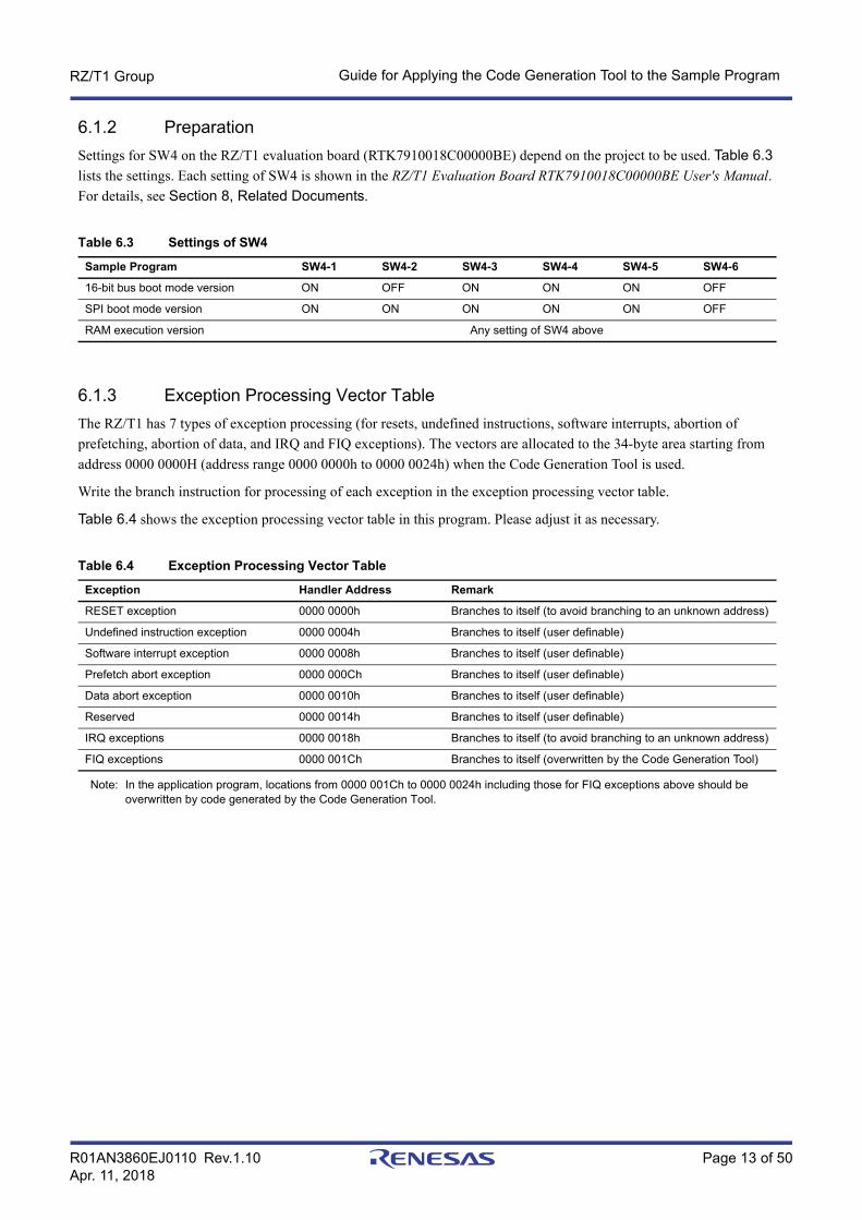
6.1.2 PreparationSettings for SW4 on the RZ/T1 evaluation board (RTK7910018C00000BE) depend on the project to be used. Table 6.3 lists the settings. Each setting of SW4 is shown in the RZ/T1 Evaluation Board RTK7910018C00000BE User's Manual. For details, see Section 8, Related Documents.
6.1.3 Exception Processing Vector TableThe RZ/T1 has 7 types of exception processing (for resets, undefined instructions, software interrupts, abortion of prefetching, abortion of data, and IRQ and FIQ exceptions). The vectors are allocated to the 34-byte area starting from address 0000 0000H (address range 0000 0000h to 0000 0024h) when the Code Generation Tool is used.
Write the branch instruction for processing of each exception in the exception processing vector table.
Table 6.4 shows the exception processing vector table in this program. Please adjust it as necessary.
Note: In the application program, locations from 0000 001Ch to 0000 0024h including those for FIQ exceptions above should be overwritten by code generated by the Code Generation Tool.
Table 6.3 Settings of SW4
Sample Program SW4-1 SW4-2 SW4-3 SW4-4 SW4-5 SW4-6
16-bit bus boot mode version ON OFF ON ON ON OFF
SPI boot mode version ON ON ON ON ON OFF
RAM execution version Any setting of SW4 above
Table 6.4 Exception Processing Vector Table
Exception Handler Address Remark
RESET exception 0000 0000h Branches to itself (to avoid branching to an unknown address)
Undefined instruction exception 0000 0004h Branches to itself (user definable)
Software interrupt exception 0000 0008h Branches to itself (user definable)
Prefetch abort exception 0000 000Ch Branches to itself (user definable)
Data abort exception 0000 0010h Branches to itself (user definable)
Reserved 0000 0014h Branches to itself (user definable)
IRQ exceptions 0000 0018h Branches to itself (to avoid branching to an unknown address)
FIQ exceptions 0000 001Ch Branches to itself (overwritten by the Code Generation Tool)
R01AN3860EJ0110 Rev.1.10 Page 14 of 50Apr. 11, 2018
RZ/T1 Group Guide for Applying the Code Generation Tool to the Sample Program
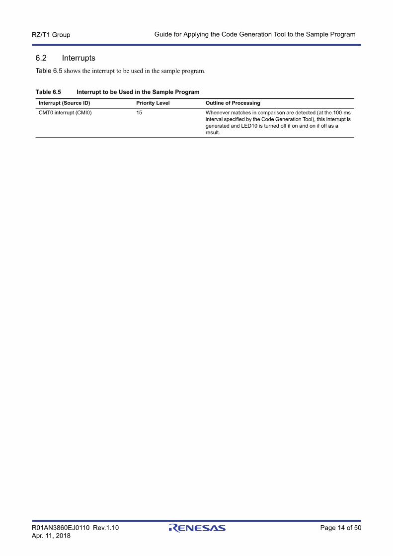
6.2 InterruptsTable 6.5 shows the interrupt to be used in the sample program.
Table 6.5 Interrupt to be Used in the Sample Program
Interrupt (Source ID) Priority Level Outline of Processing
CMT0 interrupt (CMI0) 15 Whenever matches in comparison are detected (at the 100-ms interval specified by the Code Generation Tool), this interrupt is generated and LED10 is turned off if on and on if off as a result.

R01AN3860EJ0110 Rev.1.10 Page 15 of 50Apr. 11, 2018
RZ/T1 Group Guide for Applying the Code Generation Tool to the Sample Program
6.3 Procedure for Incorporating Code from the Code Generation ToolThis section gives an example of the procedure when the Code Generation Tool is used while EWARM is the IDE. The assumed operating mode is SPI boot mode.
6.3.1 Generating Code with the Code Generation ToolIn this sample program, PORTM7 is set up to switch LED10 on and off in response to compare-match interrupts produced by the cyclic counter operation of CMT0. A description of the example of the procedure for this sample program follows.
(1) Starting the Tool for Generating Code
(2) Creating a New ProjectThe following setting is necessary to create the new project.• Select the microcontroller (an R7S910018CBG in the figure), and specify the compiler to use (that of IAR
EWARM), the name of the project, and where to create the project.
• Note on the Name and Location of the ProjectThe desired location specified by the user will be the place where the project is to be initially created with the Code Generation Tool, but the location for storage of the output file of the Code Generation Tool is separated per operating mode of the sample program.
Example of the Sample Program: Folder name for 16-bit bus boot mode: cg_src_nor Folder name for SPI boot mode: cg_src_serialFor how to incorporate each created folder into the sample program for making the initial settings of devices, refer to Section 6.3.2 (1), Importing the Environment of the code created by the Code Generation Tool (Copying).
R01AN3860EJ0110 Rev.1.10 Page 16 of 50Apr. 11, 2018
RZ/T1 Group Guide for Applying the Code Generation Tool to the Sample Program
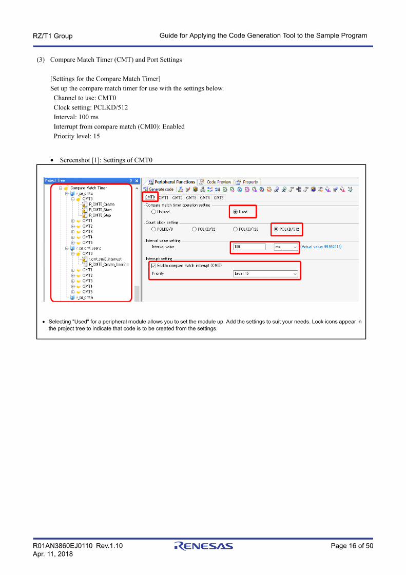
(3) Compare Match Timer (CMT) and Port Settings
[Settings for the Compare Match Timer]Set up the compare match timer for use with the settings below. Channel to use: CMT0 Clock setting: PCLKD/512 Interval: 100 ms Interrupt from compare match (CMI0): Enabled Priority level: 15
• Screenshot [1]: Settings of CMT0
• Selecting "Used" for a peripheral module allows you to set the module up. Add the settings to suit your needs. Lock icons appear in the project tree to indicate that code is to be created from the settings.

R01AN3860EJ0110 Rev.1.10 Page 17 of 50Apr. 11, 2018
RZ/T1 Group Guide for Applying the Code Generation Tool to the Sample Program
[Settings for the Port]Set up the port pin for use as listed below. Used pin: PORTM7 (connected to LED10) Input/output: Output Setting for output: Select "Output 1".
• Screenshot [2]: Setting of PORTM7
(4) Setting Modules for the Clock Signals and BusThe settings for this example are as shown for the Initial Settings sample program (SPI boot mode).
[Setting the Clock Oscillator]Make the oscillator settings listed below. Setting of boot mode: SPI boot Setting of PLL1 circuit: Check "Operation". Setting of low-speed on-chip oscillator (LOCO): Check "Operation". Clock source: PLL1 CPU clock (CPUCLK): 450 (MHz) External bus clock: 75 (MHz)
• "Output 1" is set on PM7 as the output port pin to switch LED10 on in the example of this sample program.

R01AN3860EJ0110 Rev.1.10 Page 18 of 50Apr. 11, 2018
RZ/T1 Group Guide for Applying the Code Generation Tool to the Sample Program
• Screenshot [3]: Clock Setting
Note: Values other than those framed in red are the default values of the Code Generation Tool.

R01AN3860EJ0110 Rev.1.10 Page 19 of 50Apr. 11, 2018
RZ/T1 Group Guide for Applying the Code Generation Tool to the Sample Program
[Setting the Bus State Controller]Make the settings listed below. General setting: Use Bus operation setting Setting for CS0: SRAM Setting for CS1: SRAM Setting for CS2: SDRAM Setting for CS3: Common with those for CS2 Setting for address pin selection (Address pin check setting): Group check Setting for group selection (Address pin group check setting): A1 to A25
• Screenshot [4]: Settings for the bus state controller (General setting)
Note: Values other than those framed in red are the default values of the Code Generation Tool.

R01AN3860EJ0110 Rev.1.10 Page 20 of 50Apr. 11, 2018
RZ/T1 Group Guide for Applying the Code Generation Tool to the Sample Program
CS0: Area setting: Bus width of 16 bits Bus timing setting: Numbers of cycles for each parameter External wait setting: For [External wait mask], select [External wait input is ignored]
• Screenshot [4]: Settings for the bus state controller (Settings for CS0)

R01AN3860EJ0110 Rev.1.10 Page 21 of 50Apr. 11, 2018
RZ/T1 Group Guide for Applying the Code Generation Tool to the Sample Program
CS1: Area setting: Bus width of 16 bits Bus timing setting: Numbers of cycles for each parameter External wait setting: For [External wait mask], select [External wait input is ignored]
• Screenshot [4]: Settings for the bus state controller (Settings for CS1)
CS2: Area setting: Bus width of 16 bits for CS2 (default) Area setting: Bus width of 16 bits for CS3 (default) Type: Normal SDRAM (default) Number of address bits: Numbers of address bits for rows and columns in each area Mode setting: Burst read/burst write for each area Clock select: CKIO/16 Constant register value for refresh time (Refresh compare match value): 36 Enable compare match interrupt: Release the checkmark Bus timing setting: Numbers of cycles for each parameter

R01AN3860EJ0110 Rev.1.10 Page 22 of 50Apr. 11, 2018
RZ/T1 Group Guide for Applying the Code Generation Tool to the Sample Program
• Screenshot [4]: Settings for the bus state controller (Settings for CS2)
Note: Values other than those framed in red are the default values of the Code Generation Tool.

R01AN3860EJ0110 Rev.1.10 Page 23 of 50Apr. 11, 2018
RZ/T1 Group Guide for Applying the Code Generation Tool to the Sample Program
Set the output of user functions for the same modules as in the sample program for the Initial Settings.• Generate your own code to handle processing for the initial set-up (r_xxx_user.c).
By default, code is not generated for API functions of the code generation tool that are not displayed with an icon that includes a lock. Here, we describe the setting when the R_BSC_Create_UserInit function is to be used. Select the API function in the code preview of the project tree, right-click on that entry, and select [Generate Code]. This causes the R_BSC_Create_UserInit function to be generated in the r_cg_bsc_user.c file at the time of actual code generation. When the function is selected, the icon of an open lock is displayed. For the details on usage of the Code Generation Tool, refer to AP4, Applilet3 User's Manual: Common Operations (R20UT3420EJ). Created file: r_cg_bsc_user.cThe statements for settings by API functions in the generated code will be explained in point (6), following the description of setting up and generating the code.

R01AN3860EJ0110 Rev.1.10 Page 24 of 50Apr. 11, 2018
RZ/T1 Group Guide for Applying the Code Generation Tool to the Sample Program
[Settings for the SPI Multi I/O Bus Controller] General setting: Select "External address space read mode" as the module setting. Transfer speed setting: Set "Base bit rate" as 75 Mbps Transfer format setting: Settings for clock delay, etc.
• Screenshot [5]: Settings for SPI multi I/O bus controller (General setting)
[Note]To accelerate the serial flash memory, initially set the SPIBSC to the SPI operating mode and the serial flash memory to the quad I/O mode in the sample program for the initial settings. After that, re-set the mode to that of reading from the external address space.On the other hand, in this procedure, the SPIBSC is set to be used in external address space read mode and the serial flash memory in single I/O mode. The command to be used is the FAST READ4B (0x0C) command.
Note: Values other than those framed in red are the default values of the Code Generation Tool.

R01AN3860EJ0110 Rev.1.10 Page 25 of 50Apr. 11, 2018
RZ/T1 Group Guide for Applying the Code Generation Tool to the Sample Program
[Setting]: Other types of settings are made in the red frames of the figure below.
• Screenshot [5]: Settings for the SPI multi I/O bus controller (Setting)
Note: Values other than those framed in red are the default values of the Code Generation Tool.

R01AN3860EJ0110 Rev.1.10 Page 26 of 50Apr. 11, 2018
RZ/T1 Group Guide for Applying the Code Generation Tool to the Sample Program
(5) Pin Function SettingsMake settings for those pins for which the multiplexed function is actually to be used.Example for this Sample: Each Screen for Setting and Describing Pin Functions from [Device List View] (1/3)

R01AN3860EJ0110 Rev.1.10 Page 27 of 50Apr. 11, 2018
RZ/T1 Group Guide for Applying the Code Generation Tool to the Sample Program
Example for this Sample: Each Screen for Setting and Describing Pin Functions from [Device List View] (2/3)
Example for this Sample: Each Screen for Setting and Describing Pin Functions from [Device List View] (3/3)

R01AN3860EJ0110 Rev.1.10 Page 28 of 50Apr. 11, 2018
RZ/T1 Group Guide for Applying the Code Generation Tool to the Sample Program
• Select [Device List View] from the icon on the tool bar to select the bus state controller and set BS# pin (PORT41). Setting of high driving ability output from CKIO pin (PORT10) is done in step (6), following the code generation.
Note: Pins with multiplexed functions will have their default settings immediately after release from the reset state. Make sure that the multiplexed pin functions that are actually to be used are selected. Settings for pins which are not selected as [Locked] can be changed to another setting. To avoid unnecessary contention, please select the pins to be used as [Locked] (recommended) after checking. Make sure that there are no errors that will lead to contention and so on.
(6) Code Generation and Modification with User-Defined CodeGenerate the code after completing the settings from (1) to (5).When the code is generated, the folder cg_src is created immediately below the folder cg_rc_serial, in which the project of the Code Generation Tool generated. The source code and header code are generated in the former folder.
• Modifying generated codeThe Code Generation Tool overwrites code whenever it generates new code. To merge code written by the user with newly generated code, it must be written between specific comment lines to protect it from being overwritten. [Merge file] is the default setting for file generation control.
The comment lines to indicate code to be merged are written in each file of code output by the Code Generation Tool as shown below. The comment lines protect the user code since the code between them is not overwritten in the case of merging with an existing file when code is generated again.
/* Start user code. Do not edit comment generated here */
←Write code between these lines./* End user code. Do not edit comment generated here */
Note: Please don't modify or move the comments for use in merging. If they are modified or moved, merging will not be successful.

R01AN3860EJ0110 Rev.1.10 Page 29 of 50Apr. 11, 2018
RZ/T1 Group Guide for Applying the Code Generation Tool to the Sample Program
[Setting an API function for the Bus State Controller]The code shown below should be written in modifying the file created in step (4). Target file: r_cg_bsc_user.c Target API function: R_BSC_Create_UserInit• Setting of high driving ability output for PORT10.
Setting the pin function of the clock for the bus (CKIO)• Setting of WCR for SDRAM to the CS2 space (BSC_CS2WCR_1)
When the e2studio (with equivalent functionality to AP4 1.04) is used, the additional settings should be made here.
• Calling the API function for initial settings of the SDRAM (R_BSC_InitializeSDRAM)The API function for the initial settings of the SDRAM is called in the user's own code for initialization processing.
Write the following code between the comment lines to retain user code in the target API function during the process of merging.
[Setting the API Function for Response to the Compare Match Timer]The following code is written in the interrupt processing routine by modifying the file created in step (3). Target file: r_cg_cmt_user.c Target API function: r_cmt_cmi0_interrupt• Write the code for switching LED10 on or off in the interrupt processing routine for the compare match in
response to operation of the cyclic counter.
Write the following code between the comment lines to retain user code in the target API function during the process of merging.
/* Start user code. Do not edit comment generated here */
/* Set PORT1 as high-drive output setting for connecting SDRAM */
PORT1.DSCR.WORD = 1; ←Setting of high driving ability output for PORT10 /* Set wait control register of CS2 space */
BSC.CS2WCR.CS2WCR_1.LONG = 0x00000400; ←Setting of WCR for SDRAM to the CS2 space (required only for the e2studio)
R_BSC_InitializeSDRAM(); ←Setting of API function for initial settings of SDRAM /* End user code. Do not edit comment generated here */
/* Start user code. Do not edit comment generated here */
/* Toggle the PORTM7 output level(LED10) */
PORTM.PODR.BIT.B7 ^= 1; ←Interrupt processing (switching LED10 on or off) /* End user code. Do not edit comment generated here */

R01AN3860EJ0110 Rev.1.10 Page 30 of 50Apr. 11, 2018
RZ/T1 Group Guide for Applying the Code Generation Tool to the Sample Program
[Setting the API Function for the User Application Program]After the code is generated, the file r_cg_main.c to contain the main processing is created by the Code Generation Tool under the folder cg_src. In this step, the file r_cg_main.c in the folder for the SPI boot mode version cg_src is needed to be modified.In the main processing of the user application in the file r_cg_main.c , function R_MAIN_UserInit is called. For this sample program, the calling function of the main processing as stated in the function should be common to the 16-bit bus boot version and SPI boot (serial) version. Target file: r_cg_main.c Target API function: R_MAIN_UserInit Added common main function name: user_app_main
Write the following code between the comment lines to retain user code in the target API function during the process of merging.
Note: The name of the function to act as the common main function can be as desired by the user, but it must be the same name as that of the common main function created in Section 6.3.2 (4), Creating a Common main File.
void R_MAIN_UserInit(void)
{
/* Start user code. Do not edit comment generated here */
user_app_main(); ←Common main function to be added /* End user code. Do not edit comment generated here */
}

R01AN3860EJ0110 Rev.1.10 Page 31 of 50Apr. 11, 2018
RZ/T1 Group Guide for Applying the Code Generation Tool to the Sample Program
6.3.2 Incorporation in the Sample Program of RZ/T1 Group Initial SettingsThe code generated by the Code Generation Tool should be incorporated in the EWARM version of the sample program environment for making initial settings.
As the example for this sample program, incorporation of the code generated and written in Section 6.3.1, Generating Code with the Code Generation Tool, is described below.
Remark: From this point forward, the numbers of line and etc. are described on the basis of Rev. 1.30 of the sample program of the Initial Settings. When incorporating the code from the previous steps, use the latest version of the sample program of the Initial Settings at that point in time.
(1) Importing the Environment of the code created by the Code Generation Tool (Copying)Copy the project folder of the Code Generation Tool itself which was created in 6.3.1 (2), Creating a New Project, to the folder for storage (src) of the source files among the project files of the sample program of the Initial Settings.
Examples for this Sample Program: Code Generation Tool Project name for 16-bit bus boot mode: cg_src_nor Code Generation Tool Project name for SPI boot mode: cg_src_serial
Note: Since the name of the folder created to hold the code generated by the Code Generation Tool is fixed to "cg_src", use different project names for the 16-bit bus boot mode version (cg_src_nor) and the SPI boot mode version (cg_src_serial) to contain the separate versions of the sample program.After the code is generated, each of the project folders will contain "cg_src" folder and the workspace file (.cgp).
[Supplementary Note]
When code generated by the code generation tool is incorporated in the e2studio environment, move iodefine.h from the inc folder to immediately below the project folder. For details, see Table 6.2, Folder Structure of the Sample Program of the Initial Settings Following Incorporation of the Code from the Code Generation Tool (2/2), in Section 6.1.1, Project Settings.

R01AN3860EJ0110 Rev.1.10 Page 32 of 50Apr. 11, 2018
RZ/T1 Group Guide for Applying the Code Generation Tool to the Sample Program
(2) Editing the Loader Code in the Sample Program of the Initial SettingSetting of the clock oscillator, the bus state controller, and of the SPI multi I/O bus controller which are used in the sample program of the Initial Setting should be used after having been replaced by those created in Section 6.3.1 (4), Setting Modules for the Clock Signals and Bus, with the settings made in the Code Generation Tool in that step. Therefore, the settings specified by the loader program in the sample program of the Initial Setting should be disabled (commented out).• Edit the file loader_init2.c in the common folder for the storage of source files (src) under the project folder
(RZ_T1_init_boot) of the sample program of the Initial Setting.The two points to be edited in the loader code are the 111th line and the 119th line, both in function loader_init2.
Note 1. If you plan to have the loader program speed up the clock and buses, it is possible to call the functions for various settings without commenting lines out. However, take care with this, as the settings of the clock and buses will be remade in the initial settings of later processing by the Code Generation Tool in this sample program. For details, see section 9 (1), Usage Note on the bus_init() Function.
Note 2. In the bus_init() function, the setting of the serial flash memory is changed from the single I/O mode to the quad I/O mode. However, when the code is generated in accord with this procedure, the read command (FAST READ4B) is used under the condition of the serial flash memory being in single I/O mode. When the bus_init() function is used to set the buses in the loader program, be sure to set it to quad I/O mode. For details, see section 9 (1), Usage Note on the bus_init() Function.
(3) Move the Initial Settings Function for the Error Control Module (ECM) to the Loader CodeIn the sample program of the Initial Setting the function to set the ECM up is called from the main processing. In this program, the common main created by the user should replace the main of the sample program of the Initial Setting.Therefore, move the function call for setting up the ECM (ecm_init), which handles the initial setting up of the ERROROUT pin, to the initial settings part of the loader code.• Move the ecm_init function from init_main.c to loader_init2.c (or, if you are using the DS-5 IDE, cpu_init.c).
The file init_main.c should be under the sample folder of the folder for the storage of source files (src) in the project file of the sample program of the Initial Setting.Setting of extended pseudo-error 35 for ECM is not necessary, so it should be removed.Processing of the extended pseudo-error for ECM in loader_init2.c should also be removed.
The following lines of the file init_main.c should be copied to the file loader_init2.c.
Source of copying: File init_main.c• (1) Function definition, 86th line
• (2) Calling function ecm_init from the 117th (comment) and 118th (call) lines of the main function
/* Set CPU clock and LOCO clock */
// cpg_init(); ←Comment out the function for initial settings of the clock oscillator.*1
*snip*
/* Initialize the bus settings */
// bus_init(); ←Comment out the function for initial settings of the bus controllers (BSC, SPIBSC).*2
void ecm_init(void);
/* Initialize the ECM function */
ecm_init();

R01AN3860EJ0110 Rev.1.10 Page 33 of 50Apr. 11, 2018
RZ/T1 Group Guide for Applying the Code Generation Tool to the Sample Program
• (3) The code for the ecm_init function is from the 177th line to the 202nd line.
Destination file for copying: File loader_init2.c• Add the function declaration that was copied in step (1) to "Private variables and functions" as the 98th line.
• Place the call of ecm_init() between the calls of function set_low_vec and function main in the processing by loader_init2.Add the call of function ecm_init from step (2) as the 129th line.
Note 1. The processing of function ecm_init is placed in the ATCM. Therefore, the DMB instruction is added to ensure the wait setting of ATCM, executed by R_ATCM_WaitSet() immediately before the processing.
/*******************************************************************************
* Function Name: ecm_init
*snip********************************************************************************/
void ecm_init(void)
{
*snip*}
/*******************************************************************************
End of function ecm_init
*******************************************************************************/
/*******************************************************************************
Private variables and functions
*******************************************************************************/
void loader_init2(void);
void reset_check(void);
void cpg_init(void);
void copy_to_atcm(void);
void copy_4byte(uint32_t *src, uint32_t *dst, uint32_t bytesize);
void ecm_init(void); ←Add the declaration of function ecm_init.
void loader_init2(void)
{
*snip* /* Set RZ/T1 to Low-vector (SCTLR.V = 0) */
set_low_vec();
/* Wait for ensuring the wait setting of ATCM */
asm("dmb"); /* Ensuring Context-changing */ ←Added waiting for the wait setting of ATCM*1
/* Initialize the ECM function */
ecm_init(); ←Add call of function ecm_init. /* Jump to _main() */
_main();
}
R01AN3860EJ0110 Rev.1.10 Page 34 of 50Apr. 11, 2018
RZ/T1 Group Guide for Applying the Code Generation Tool to the Sample Program
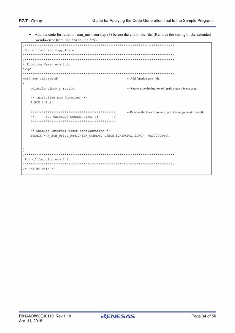
• Add the code for function ecm_init from step (3) before the end of the file. (Remove the setting of the extended pseudo-error from line 354 to line 359)
/*******************************************************************************
End of function copy_4byte
*******************************************************************************/
/*******************************************************************************
* Function Name: ecm_init
*snip********************************************************************************/
void ecm_init(void) ←Add function ecm_init.{
volatile uint8_t result; ←Remove the declaration of result, since it is not used /* Initialize ECM function */
R_ECM_Init();
/*******************************************/ ←Remove the lines from here up to the assignment to result. /* Set extended pseudo error 35 */
/*******************************************/
/* Enables internal reset configuration */
result = R_ECM_Write_Reg32(ECM_COMMON, &(ECM.ECMIRCFG1.LONG), 0x00000004);
}
/*******************************************************************************
End of function ecm_init
*******************************************************************************/
/* End of File */

R01AN3860EJ0110 Rev.1.10 Page 35 of 50Apr. 11, 2018
RZ/T1 Group Guide for Applying the Code Generation Tool to the Sample Program
• Remove the processing of the extended pseudo-error for ECM from the reset_check function in loader_init2./*******************************************************************************
* Function Name : reset_check
* Description : Check the reset source and execute the each sequence.
* When error source number 35 is generated, set P77 pin to High.
* Arguments : none
* Return Value : none
*******************************************************************************/
void reset_check(void)
{
volatile uint8_t result; ← Remove the declaration of result, since it is not used volatile uint32_t dummy; ← Remove the declaration of dummy, since it is not used /* Check the reset status flag and execute the each sequence */
if (RST_SOURCE_ECM == SYSTEM.RSTSR0.LONG) // ECM reset is generated
{
/* Clear reset status flag */
R_RST_WriteEnable(); // Enable writing to the RSTSR0 register
SYSTEM.RSTSR0.LONG = 0x00000000; // Clear reset factor flag
R_RST_WriteDisable(); // Disable writing to the RSTSR0 register
/* Check the ECM error source */ ←Remove the if statement and the processing in case the condition is satisfied below
if (1 == ECMM.ECMMESSTR1.BIT.ECMMSSE102) // Error source number 35 is generated
{
*snip*
}
*snip*
/*******************************************************************************
End of function reset_check
*******************************************************************************/
}

R01AN3860EJ0110 Rev.1.10 Page 36 of 50Apr. 11, 2018
RZ/T1 Group Guide for Applying the Code Generation Tool to the Sample Program
(4) Creating a Common main FileIn user application programs created with the Code Generation Tool, different files are used in the 16-bit bus boot mode version and SPI boot mode version.The main processing which is common to both the 16-bit bus boot mode version and the SPI boot mode version should be created in a common main file.For this sample program, it should be created in the sample folder where the source files are stored (src) in the project file of the same sample program of the Initial Setting as file init_main.c, since it is the common main function.The names of files can be selected as desired by the user. In this sample program, the names of the functions to be created should be called from the user application program created with the Code Generation Tool so they should be as below.
Example for this Sample Program: Common main function to be created: user_app_main File to be created: user_main.c
Create the file as follows with reference to the user_main.c file for this program.~
/*******************************************************************************
Includes <System Includes> , "Project Includes"
*******************************************************************************/
#include "r_cg_cmt.h" ←Include file of definitions for the CMT0 Function#include "iodefine.h"
#include "r_system.h"
/*******************************************************************************
*snip*/*******************************************************************************
Private variables and functions
*******************************************************************************/
void user_app_main(void); ←Declaration of function user_app_main.
/*******************************************************************************
* Outline : user main processing
* Function Name: user_app_main
*snip********************************************************************************/
void user_app_main (void) ←Body of function user_app_main{
R_CMT0_Start(); ←Start use of CMT0 by the sample program}
/*******************************************************************************
End of function main
*******************************************************************************/
/* End of File */

R01AN3860EJ0110 Rev.1.10 Page 37 of 50Apr. 11, 2018
RZ/T1 Group Guide for Applying the Code Generation Tool to the Sample Program
(5) Setting the target source code from the Code Generation Tool to be compiledIn the case of EWARM, set the source code from the Code Generation Tool to be compiled for the sample program in the initial settings by following the procedure below.
[Add Project Connection]• Select [Add Project Connection...] from the [Project] menu. The [Add Project Connection] dialog box should be
displayed.Select [IAR Project Connection] for [Connect using] and click on [OK].
• Screen [5]-1 Adding a Project Connection
• The [Select IAR Project Connection File] dialog box should be displayed. Select [IAR Project Connection File] (.ipcf) and click on [Open].The project file for connection includes the registered information of the source files.The files selected here should be created after the code has been generated in the following folder (recommended) by the Code Generation Tool.
Examples of folder names for reference: Folder name of 16-bit bus boot version: cg_src_nor Folder name of SPI boot mode version: cg_src_serial
The files to be compiled should be added as shown below after they are completed.

R01AN3860EJ0110 Rev.1.10 Page 38 of 50Apr. 11, 2018
RZ/T1 Group Guide for Applying the Code Generation Tool to the Sample Program
• Screen [5]-2 Example of the addition of files to be compiled
Remark: In DS-5 and e2studio, when a file is added to the folder created by the Code Generation Tool, the project automatically recognizes the file.
Note: Regarding the use of [Add Project Connection], see section 3.12.1, How to create a project connection between IAR Embedded Workbench and AP4, in AP4, Applilet3 Common Operations User's Manual (R20UT3420EJ).
R01AN3860EJ0110 Rev.1.10 Page 39 of 50Apr. 11, 2018
RZ/T1 Group Guide for Applying the Code Generation Tool to the Sample Program
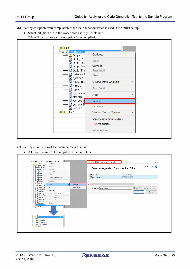
(6) Setting exception from compilation of the main function which is used in the initial set-up• Select init_main file in the work space and right-click on it.
Select [Remove] to set the exception from compilation.
(7) Setting compilation of the common main function• Add user_main.c to be compiled in the init folder.

R01AN3860EJ0110 Rev.1.10 Page 40 of 50Apr. 11, 2018
RZ/T1 Group Guide for Applying the Code Generation Tool to the Sample Program
(8) Set the include path for incorporating of the newly added code output by the Code Generation Tool• Select [Options...] from the [Project] menu and select [C/C + + Compiler] → [Preprocessor].
Add the folder created by the code generation tool to the setting for additional include directories with the path to the working files as in the example below.
Example for this Sample Program:$PROJ_DIR$\src\cg_src_serial\cg_src
R01AN3860EJ0110 Rev.1.10 Page 41 of 50Apr. 11, 2018
RZ/T1 Group Guide for Applying the Code Generation Tool to the Sample Program
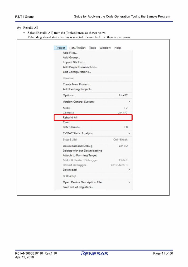
(9) Rebuild All• Select [Rebuild All] from the [Project] menu as shown below.
Rebuilding should start after this is selected. Please check that there are no errors.

R01AN3860EJ0110 Rev.1.10 Page 42 of 50Apr. 11, 2018
RZ/T1 Group Guide for Applying the Code Generation Tool to the Sample Program
(10) Downloading and Debugging• Select [Download and Debug] from [Project] on the tool bar as shown below. After the emulator is connected,
the program will be written to the external serial flash memory by the dedicated flash downloader. You can then start debugging.

R01AN3860EJ0110 Rev.1.10 Page 43 of 50Apr. 11, 2018
RZ/T1 Group Guide for Applying the Code Generation Tool to the Sample Program
6.4 Fixed-Width Integer TypesTable 6.6 lists fixed-width integer types for the sample code.
6.5 FunctionRefer to the application note of the RZ/T1 Group Initial Settings products for the functions of the sample program of the Initial Setting that are also used in this sample program. Table 6.7 below only lists the function to be added to the sample program of the Initial Setting.
Table 6.6 Fixed-Width Integer Types for the Sample Code
Symbol Description
int8_t 8-bit signed integer (defined in the standard library)
int16_t 16-bit signed integer (defined in the standard library)
int32_t 32-bit signed integer (defined in the standard library)
uint8_t 8-bit unsigned integer (defined in the standard library)
uint16_t 16-bit unsigned integer (defined in the standard library)
uint32_t 32-bit unsigned integer (defined in the standard library)
Table 6.7 Function
Function Name
user_app_main

R01AN3860EJ0110 Rev.1.10 Page 44 of 50Apr. 11, 2018
RZ/T1 Group Guide for Applying the Code Generation Tool to the Sample Program
6.6 Flowchart
6.6.1 Loader Program ProcessingFigure 6.3 is a flowchart of processing by the loader program.
Refer to the application note on initial settings for RZ/T1 group products for details of the flow of the loader program part.
Figure 6.3 Loader Program Processing
Start of loader program
Initial settings for the stack, VFP, and variables (for the loader program)
Judgment of ATCM wait time
Settings for the MPU and the cache
Branch to the user application program
ECM settingsTaken from the main function of the initial settings program
Judgment of reset
Transfer of the application program
Setting the low vector

R01AN3860EJ0110 Rev.1.10 Page 45 of 50Apr. 11, 2018
RZ/T1 Group Guide for Applying the Code Generation Tool to the Sample Program
6.6.2 Processing by the Application Program Created by the Code Generation ToolFigure 6.4 is a flowchart of the application program created by the Code Generation Tool.
Note: The API functions generated by the Code Generation Tool are used. The main function of the user application becomes the main processing produced by the Code Generation Tool for each of the boot modes that are selected.
Figure 6.4 Application Program Created by the Code Generation Tool
Code Generation Tool Starting the user application program
Run the user applicationmain function
Register the FIQ handler
Perform dummy writing to the VIC.HVA0 register
Make the pin-function settingsMPC and port settings
Set the clock oscillator (450 MHz)Clock-frequency settings for the CPU
and peripheral I/O modules
Set the bus-state controller (BSC)Memory-bus (CSx) wait and external bus clock settings
Set the pin for use by the userPort settings
Set the timer for use by the user/Set the timer interruptCMT0 settings
Make the SPI multi I/O bus controller settings (SPIBSC)Memory bus (SPIBSC) wait setting
Branch to common main

R01AN3860EJ0110 Rev.1.10 Page 46 of 50Apr. 11, 2018
RZ/T1 Group Guide for Applying the Code Generation Tool to the Sample Program
6.6.3 Common main ProcessingFigure 6.5 shows the flowchart of the common main processing.
6.6.4 Interrupt Processing by the Timer Selected by the User (CMT0)Figure 6.6 is a flowchart of processing in response to interrupts from the timer selected by the user (CMT0)
Figure 6.5 Common main Processing
Figure 6.6 Interrupt Processing by the Timer Selected by the User (CMT0)
Common main function
Setting to start the timer for use by the user (CMT0)
Handling the interrupt from the timer for use by the user (CMT0)
Switch LED10 on if it is off and off if it is on.
return

R01AN3860EJ0110 Rev.1.10 Page 47 of 50Apr. 11, 2018
RZ/T1 Group Guide for Applying the Code Generation Tool to the Sample Program
7. Sample ProgramThe sample program can be downloaded from the Renesas Electronics website.

R01AN3860EJ0110 Rev.1.10 Page 48 of 50Apr. 11, 2018
RZ/T1 Group Guide for Applying the Code Generation Tool to the Sample Program
8. Related Documents• User's Manual: Hardware
RZ/T1 Group User's Manual: HardwareDownload the latest version from the Renesas Electronics website.
RZ/T1 Evaluation Board RTK7910022C00000BR User's Manual Download the latest version from the Renesas Electronics website.
• Technical Update and Technical NewsDownload the latest version from the Renesas Electronics website.
• User's manuals related to the development environmentThe latest version for the IAR integrated development environment (IAR Embedded Workbench® for ARM) is available from the IAR Systems website.
The latest version for the ARM integrated development environment (Development Studio 5TM) is available from the ARM website.
The latest version for the Renesas Electronics integrated development environment (e2studio) is available from the Renesas Electronics website.

R01AN3860EJ0110 Rev.1.10 Page 49 of 50Apr. 11, 2018
RZ/T1 Group Guide for Applying the Code Generation Tool to the Sample Program
9. Usage Note(1) Usage Note on the bus_init() Function
In this sample program, the bus_init() function that is the base program of the initial setting sample program is used without lines commented out. Therefore, when the bus_init() function is used while setting buses in the loader program, take care on the following points.
In the bus_init() function, the setting of the serial flash memory is changed from the single I/O mode to the quad I/O mode. On the other hand, as the function is expected to operate in single I/O mode in this sample program, reading of the serial flash memory does not proceed normally. When the bus_init() function is used, settings for the quad I/O mode are required as described in Section 6.3.1 (4), Setting Modules for the Clock Signals and Bus, [Settings for the SPI Multi I/O Bus Controller], such as setting 0xEC (4READ4B) in the command.

R01AN3860EJ0110 Rev.1.10 Page 50 of 50Apr. 11, 2018
RZ/T1 Group Guide for Applying the Code Generation Tool to the Sample Program
Website and SupportRenesas Electronics website
http://www.renesas.com/
Inquiries
http://www.renesas.com/contact/

C - 1
Revision History Guide for Applying the Code Generation Tool to the Sample Program
Rev. DateDescription
Page Summary1.00 Jun. 30, 2017 — First Edition issued1.10 Apr. 11, 2018 2. Operating Environment
4 Table 2.1 Operating Environment, Tool for generating code: The version of the AP4 from Renesas, modified. Note modified.
3. Related Application Notes5 Application note document numbers, added
6. Software13 6.1.3 Exception Processing Vector Table: The address of the 34-byte area, modified13 Table 6.4 Exception Processing Vector Table, Note: The address, modified16 6.3.1 Generating Code with the Code Generation Tool: The description on the code gener-
ation tool, modified24 Screenshot [5]: Settings for SPI multi I/O bus controller (General setting), modified. Note
modified.25 Screenshot [5]: Settings for the SPI multi I/O bus controller (Setting), modified27 Example for this Sample: Each Screen for Setting and Describing Pin Functions from
[Device List View] (3/3), modified29 The description of [Setting an API function for the Bus State Controller] in section 6.3.1,
modified. The description on the code, modified31 6.3.2 Incorporation in the Sample Program of RZ/T1 Group Initial Settings, Remark: The
revision of the sample program of the initial settings, modified32 6.3.2, (2) Editing the Loader Code in the Sample Program of the Initial Setting: Note 1,
modified. Note 2, added.33 6.3.2, (3): loader_init2.c processing: The waiting function for the wait setting of ATCM was
added beween set_low_vec(); and /* Initialize the ECM function */. Note 1, added.9. Usage Note
49 9. Usage Note, added
All trademarks and registered trademarks are the property of their respective owners.

General Precautions in the Handling of Microprocessing Unit and Microcontroller Unit Products
The following usage notes are applicable to all Microprocessing unit and Microcontroller unit products from Renesas.
For detailed usage notes on the products covered by this document, refer to the relevant sections of the document as well
as any technical updates that have been issued for the products.
1. Handling of Unused PinsHandle unused pins in accordance with the directions given under Handling of Unused Pins in the manual.⎯ The input pins of CMOS products are generally in the high-impedance state. In operation with an
unused pin in the open-circuit state, extra electromagnetic noise is induced in the vicinity of LSI, an associated shoot-through current flows internally, and malfunctions occur due to the false recognition of the pin state as an input signal become possible. Unused pins should be handled as described under Handling of Unused Pins in the manual.
2. Processing at Power-onThe state of the product is undefined at the moment when power is supplied.⎯ The states of internal circuits in the LSI are indeterminate and the states of register settings and
pins are undefined at the moment when power is supplied.In a finished product where the reset signal is applied to the external reset pin, the states of pins are not guaranteed from the moment when power is supplied until the reset process is completed.In a similar way, the states of pins in a product that is reset by an on-chip power-on reset functionare not guaranteed from the moment when power is supplied until the power reaches the level at which resetting has been specified.
3. Prohibition of Access to Reserved AddressesAccess to reserved addresses is prohibited.⎯ The reserved addresses are provided for the possible future expansion of functions. Do not access
these addresses; the correct operation of LSI is not guaranteed if they are accessed.4. Clock Signals
After applying a reset, only release the reset line after the operating clock signal has become stable. When switching the clock signal during program execution, wait until the target clock signal has stabilized.⎯ When the clock signal is generated with an external resonator (or from an external oscillator)
during a reset, ensure that the reset line is only released after full stabilization of the clock signal. Moreover, when switching to a clock signal produced with an external resonator (or by an external oscillator) while program execution is in progress, wait until the target clock signal is stable.
5. Differences between ProductsBefore changing from one product to another, i.e. to a product with a different part number, confirm that the change will not lead to problems.⎯ The characteristics of Microprocessing unit or Microcontroller unit products in the same group but
having a different part number may differ in terms of the internal memory capacity, layout pattern, and other factors, which can affect the ranges of electrical characteristics, such as characteristic values, operating margins, immunity to noise, and amount of radiated noise. When changing to a product with a different part number, implement a system-evaluation test for the given product.
General Precautions in the Handling of MPU/MCU Products
http://www.renesas.comRefer to "http://www.renesas.com/" for the latest and detailed information.
Renesas Electronics America Inc.1001 Murphy Ranch Road, Milpitas, CA 95035, U.S.A.Tel: +1-408-432-8888, Fax: +1-408-434-5351Renesas Electronics Canada Limited9251 Yonge Street, Suite 8309 Richmond Hill, Ontario Canada L4C 9T3Tel: +1-905-237-2004Renesas Electronics Europe LimitedDukes Meadow, Millboard Road, Bourne End, Buckinghamshire, SL8 5FH, U.KTel: +44-1628-651-700, Fax: +44-1628-651-804Renesas Electronics Europe GmbHArcadiastrasse 10, 40472 Düsseldorf, Germany Tel: +49-211-6503-0, Fax: +49-211-6503-1327Renesas Electronics (China) Co., Ltd.Room 1709 Quantum Plaza, No.27 ZhichunLu, Haidian District, Beijing, 100191 P. R. ChinaTel: +86-10-8235-1155, Fax: +86-10-8235-7679Renesas Electronics (Shanghai) Co., Ltd.Unit 301, Tower A, Central Towers, 555 Langao Road, Putuo District, Shanghai, 200333 P. R. China Tel: +86-21-2226-0888, Fax: +86-21-2226-0999Renesas Electronics Hong Kong LimitedUnit 1601-1611, 16/F., Tower 2, Grand Century Place, 193 Prince Edward Road West, Mongkok, Kowloon, Hong KongTel: +852-2265-6688, Fax: +852 2886-9022Renesas Electronics Taiwan Co., Ltd.13F, No. 363, Fu Shing North Road, Taipei 10543, TaiwanTel: +886-2-8175-9600, Fax: +886 2-8175-9670Renesas Electronics Singapore Pte. Ltd.80 Bendemeer Road, Unit #06-02 Hyflux Innovation Centre, Singapore 339949Tel: +65-6213-0200, Fax: +65-6213-0300Renesas Electronics Malaysia Sdn.Bhd.Unit 1207, Block B, Menara Amcorp, Amcorp Trade Centre, No. 18, Jln Persiaran Barat, 46050 Petaling Jaya, Selangor Darul Ehsan, MalaysiaTel: +60-3-7955-9390, Fax: +60-3-7955-9510Renesas Electronics India Pvt. Ltd.No.777C, 100 Feet Road, HAL 2nd Stage, Indiranagar, Bangalore 560 038, IndiaTel: +91-80-67208700, Fax: +91-80-67208777Renesas Electronics Korea Co., Ltd.17F, KAMCO Yangjae Tower, 262, Gangnam-daero, Gangnam-gu, Seoul, 06265 KoreaTel: +82-2-558-3737, Fax: +82-2-558-5338
SALES OFFICES
© 2018 Renesas Electronics Corporation. All rights reserved.Colophon 7.0
(Rev.4.0-1 November 2017)
Notice
1. Descriptions of circuits, software and other related information in this document are provided only to illustrate the operation of semiconductor products and application examples. You are fully responsible for
the incorporation or any other use of the circuits, software, and information in the design of your product or system. Renesas Electronics disclaims any and all liability for any losses and damages incurred by
you or third parties arising from the use of these circuits, software, or information.
2. Renesas Electronics hereby expressly disclaims any warranties against and liability for infringement or any other claims involving patents, copyrights, or other intellectual property rights of third parties, by or
arising from the use of Renesas Electronics products or technical information described in this document, including but not limited to, the product data, drawings, charts, programs, algorithms, and application
examples.
3. No license, express, implied or otherwise, is granted hereby under any patents, copyrights or other intellectual property rights of Renesas Electronics or others.
4. You shall not alter, modify, copy, or reverse engineer any Renesas Electronics product, whether in whole or in part. Renesas Electronics disclaims any and all liability for any losses or damages incurred by
you or third parties arising from such alteration, modification, copying or reverse engineering.
5. Renesas Electronics products are classified according to the following two quality grades: “Standard” and “High Quality”. The intended applications for each Renesas Electronics product depends on the
product’s quality grade, as indicated below.
"Standard": Computers; office equipment; communications equipment; test and measurement equipment; audio and visual equipment; home electronic appliances; machine tools; personal electronic
equipment; industrial robots; etc.
"High Quality": Transportation equipment (automobiles, trains, ships, etc.); traffic control (traffic lights); large-scale communication equipment; key financial terminal systems; safety control equipment; etc.
Unless expressly designated as a high reliability product or a product for harsh environments in a Renesas Electronics data sheet or other Renesas Electronics document, Renesas Electronics products are
not intended or authorized for use in products or systems that may pose a direct threat to human life or bodily injury (artificial life support devices or systems; surgical implantations; etc.), or may cause
serious property damage (space system; undersea repeaters; nuclear power control systems; aircraft control systems; key plant systems; military equipment; etc.). Renesas Electronics disclaims any and all
liability for any damages or losses incurred by you or any third parties arising from the use of any Renesas Electronics product that is inconsistent with any Renesas Electronics data sheet, user’s manual or
other Renesas Electronics document.
6. When using Renesas Electronics products, refer to the latest product information (data sheets, user’s manuals, application notes, “General Notes for Handling and Using Semiconductor Devices” in the
reliability handbook, etc.), and ensure that usage conditions are within the ranges specified by Renesas Electronics with respect to maximum ratings, operating power supply voltage range, heat dissipation
characteristics, installation, etc. Renesas Electronics disclaims any and all liability for any malfunctions, failure or accident arising out of the use of Renesas Electronics products outside of such specified
ranges.
7. Although Renesas Electronics endeavors to improve the quality and reliability of Renesas Electronics products, semiconductor products have specific characteristics, such as the occurrence of failure at a
certain rate and malfunctions under certain use conditions. Unless designated as a high reliability product or a product for harsh environments in a Renesas Electronics data sheet or other Renesas
Electronics document, Renesas Electronics products are not subject to radiation resistance design. You are responsible for implementing safety measures to guard against the possibility of bodily injury, injury
or damage caused by fire, and/or danger to the public in the event of a failure or malfunction of Renesas Electronics products, such as safety design for hardware and software, including but not limited to
redundancy, fire control and malfunction prevention, appropriate treatment for aging degradation or any other appropriate measures. Because the evaluation of microcomputer software alone is very difficult
and impractical, you are responsible for evaluating the safety of the final products or systems manufactured by you.
8. Please contact a Renesas Electronics sales office for details as to environmental matters such as the environmental compatibility of each Renesas Electronics product. You are responsible for carefully and
sufficiently investigating applicable laws and regulations that regulate the inclusion or use of controlled substances, including without limitation, the EU RoHS Directive, and using Renesas Electronics
products in compliance with all these applicable laws and regulations. Renesas Electronics disclaims any and all liability for damages or losses occurring as a result of your noncompliance with applicable
laws and regulations.
9. Renesas Electronics products and technologies shall not be used for or incorporated into any products or systems whose manufacture, use, or sale is prohibited under any applicable domestic or foreign laws
or regulations. You shall comply with any applicable export control laws and regulations promulgated and administered by the governments of any countries asserting jurisdiction over the parties or
transactions.
10. It is the responsibility of the buyer or distributor of Renesas Electronics products, or any other party who distributes, disposes of, or otherwise sells or transfers the product to a third party, to notify such third
party in advance of the contents and conditions set forth in this document.
11. This document shall not be reprinted, reproduced or duplicated in any form, in whole or in part, without prior written consent of Renesas Electronics.
12. Please contact a Renesas Electronics sales office if you have any questions regarding the information contained in this document or Renesas Electronics products.
(Note 1) “Renesas Electronics” as used in this document means Renesas Electronics Corporation and also includes its directly or indirectly controlled subsidiaries.
(Note 2) “Renesas Electronics product(s)” means any product developed or manufactured by or for Renesas Electronics.
ご注意書き