All 90A approved plots project in neemrana behror @782782'7623

UNITED STATES DEPARTMENT OF AGRICULTURE Rural Utilities Service
RUS BULLETIN 1753F-601a (PE-90a)
SUBJECT: MINIMUM PERFORMANCE SPECIFICATION FOR FIBER OPTIC CABLES (FOR BACKBONE, FEEDER AND DISTRIBUTION PLANT)
TO: All Telecommunications Program Borrowers, Cable Manufacturers and Staff
EFFECTIVE DATE: Date of Approval.
OFFICE OF PRIMARY INTEREST: Technical Support Branch
INSTRUCTIONS: This bulletin replaces RUS Bulletin 1753F-601.
AVAILABILITY: This bulletin can be accessed via the Internet at http://www.usda.gov/rus/telecomJpublications/bulletins.htm
PURPOSE: This bulletin updates the fiber optic cable specifications to meet current industry standards; includes additional requirements to meet the construction requirements of fiber-to-thehome construction; clarifies certain existing definitions; and separates the existing bulletin (RUS Bulletin 1753F-601) into two distinct bulletins. This bulletin covers minimum requirements for cables intended to be used for backbone, feeder and distribution plant systems (RUS Bulletin 1753F-601a). For service entrance cables, see RUS Bulletin 1753F-601b.
This bulletin is a user friendly guide and a refonnat of the text codified in 7 CFR 1755.900, 1755.901, and 1755.902, published at 20560 Federal Register / Vol. 74, No. 85, dated Tuesday, May 5,2009. Every effort has been made to ensure the accuracy of this document. However, in case of discrepancies, the regulations at 7 CFR 1755.900, 1755.901, and 1755.902 are the authorized sources.
ACKNOWLEDGMENT: The reproduction of copyrighted Insulated Cable Engineers Association (lCEA) tables is with pennission of ICEA and is for infonnation purposes. The reader is cautioned that the ICEA Standards are under constant revision and is advised to check ICEA for subsequent changes or modifications. RUS thanks ICEA for granting pennission to reprint many of the tables found in ANSI/ICEA S-87-640-2006, Standard/or Optical Fiber Outside Plant Communications Cable, 4th edition, December 2006. The reproduction of these tables makes available general infonnation of interest to our borrowers, engineers, and contractors.
•
Date

RUS BULLETIN 1753F-601a Page 2 of 44
TABLE OF CONTENTS
ABBREVIATIONS
DEFINITIONS
APPENDIX TO §1755.902 (Qualifications Test Data)
1 INCORPORATION BY REFERENCE
2 MINIMUM PERFORMANCE SPECIFICATION FOR
FIBER OPTIC CABLES
a Scope b Optical Fibers c Buffers d Fiber Identification e Optical Fiber Ribbon f Strength Members g Cable Core h Core Water Blocking i Water Blocking Material j Core Wrap k Inner Jackets l Outer Jacket m Armor n Figure 8 Aerial Cables o Sheath Slitting Cord p Identification Markers q Performance of a Finished Cable r Mechanical Requirements s Pre-connectorized Cable t Acceptance Testing u Records Tests v Manufacturing Irregularities w Packaging and Preparation for Shipment

RUS BULLETIN 1753F-601a Page 3 of 44
ABBREVIATIONS
ADSS All dielectric self-supporting ASTM American Society for Testing and Materials °C Centigrade temperature scale dB Decibel CSM Central strength member dB/km Decibels per 1 kilometer ECCS Electrolytic chrome coated steel EIA Electronic Industries Alliance EIA/TIA Electronic Industries Alliance/Telecommunications Industry Association; FTTH Fiber-to-the-Home Gbps Gigabit per second or Gbit/s GE General Electric HDPE High density polyethylene ICEA Insulated Cable Engineers Association, Inc. Km kilometer(s) LDPE Low density polyethylene m meter(s) Max. Maximum Mbit Megabits MDPE Medium density polyethylene MHz-km Megahertz-kilometer Min. Minimum MFD Mode-Field Diameter nm Nanometer(s) N Newton(s) NA Numerical aperture NESC National Electrical Safety Code OC Optical cable O.D. Outside Diameter OF Optical fiber OSHA Occupational Safety and Health Administration OTDR Optical Time Domain Reflectometer % Percent ps/(nm·km) Picosecond per nanometer times kilometer ps/(nm2·km) Picosecond per nanometer squared times kilometer PMD Polarization Mode Dispersion RUS Rural Utilities Service s Seconds(s) SI International System (of Units) (From the French Système
international d'unités) µm Micrometer

RUS BULLETIN 1753F-601a Page 4 of 44
DEFINITIONS
Accept; Acceptance means Agency action of providing the manufacturer of a product with a letter by mail or facsimile that the Agency has determined that the manufacturer’s product meets its requirements. For information on how to obtain Agency product acceptance, refer to the procedures listed at http://www.usda.gov/rus/telecom/listing_procedures/index_listing_procedures.htm, as well as additional information in RUS Bulletin 345-3, Acceptance of Standards, Specifications, Equipment Contract Forms, Manual Sections, Drawings, Materials and Equipment for the Telephone Program, available for download at http://www.usda.gov/rus/telecom/publications/bulletins.htm. Agency means the Rural Utilities Service, an Agency of the United States Department of Agriculture. Armor means a metal tape installed under the outer jacket of the cable intended to provide mechanical protection during cable installation and environmental protection against rodents, termites, etc. Attenuation means the loss of power as the light travels in the fiber usually expressed in dB/km. Bandwidth means the range of signal frequencies that can be transmitted by a communications channel with defined maximum loss or distortion. Bandwidth indicates the information-carrying capacity of a channel. Birefringence means the decomposition of a pulse of light entering the fiber into “two polarized pulses” traveling at different velocities due to the different refractive indexes in the polarization axes in which the electric fields oscillate. Different refractive indexes in the fiber may be caused by an asymmetric fiber core, internal manufacturing stresses, or through external stresses from cabling and installation of the fiber optic cable, such as bending and twisting. Cable cutoff wavelength means the shortest wavelength at which only one mode light can be transmitted in any of the single mode fibers of an optical fiber cable. Chromatic Dispersion means the broadening of a light pulse as it travels down the length of an optical fiber, resulting in different spectral components of the light pulse traveling at different speeds, due to the fact that the index of refraction of the fiber core is different for different wavelengths. Cladding means the outer layer of an optical fiber made of glass or other transparent material that is fused to the fiber core. The cladding concentrically surrounds the fiber core. It has a lower refractive index than the core, so light travelling in the fiber is maintained in the core by internal reflection at the core-cladding interface.

RUS BULLETIN 1753F-601a Page 5 of 44
Core means the central region of an optical waveguide or fiber which has a higher refractive index than the cladding through which light is transmitted. Cutoff Wavelength means, in single mode fiber, the shortest wavelength at which only the fundamental mode of an optical wavelength can propagate. Dielectric Cable means a cable which has neither metallic members nor other electrically conductive materials or elements. Differential Group Delay means the arrival time differential of the two polarized light components of a light pulse traveling through the optical fiber due to birefringence. Graded Refractive Index Profile means the refractive index profile of an optical fiber that varies smoothly with radius from the center of the fiber to the outer boundary of the cladding. List of Acceptable Materials means the latest edition of RUS Informational Publication 344–2, ‘‘List of Materials Acceptable for Use on Telecommunications Systems of RUS Borrowers.” This document contains a convenient listing of products which have been determined to be acceptable by the Agency. The List of Acceptable Materials is available on the Internet at http://www.usda.gov/rus/telecom/materials/index_listomat.htm. Loose Tube Buffer means the protective tube that loosely contains the optical fibers within the fiber optic cable, often filled with suitable water blocking material. Matched Cable means fiber optic cable manufactured to meet the requirement of this section for which the calculated splice loss using the formula below is ≤ 0.06 dB for any two cabled fibers to be spliced. LOSS (dB) = -10 LOG10 [4/(MFD1/MFD2 + MFD2/MFD1)2],
where subscripts 1 and 2 refer to any two cabled fibers to be spliced. Mil means a measurement unit of length indicating one thousandth of an inch. Minimum Bending Diameter means the smallest diameter that must be maintained while bending a fiber optic cable to avoid degrading cable performance indicated as a multiple of the cable diameter (Bending Diameter/Cable Diameter). Mode-Field Diameter means the diameter of the cross-sectional area of an optical fiber which includes the core and portion of the cladding where the majority of the light travels in a single mode fiber. Multimode Fiber means an optical fiber in which light travels in more than one bound mode. A multimode fiber may either have a graded index or step index refractive index profile.

RUS BULLETIN 1753F-601a Page 6 of 44
Numerical Aperture (NA) means an optical fiber parameter that indicates the angle of acceptance of light into a fiber. Optical Fiber means any fiber made of dielectric material that guides light. Optical Point Discontinuities means the localized deviations of the optical fiber loss characteristic which location and magnitude may be determined by appropriate OTDR measurements of the fiber. Optical Waveguide means any structure capable of guiding optical power. In optical communications, the term generally refers to a fiber designed to transmit optical signals. Polarization Mode Dispersion means, for a particular length of fiber, the average of the differential group delays of the two polarized components of light pulses traveling in the fiber, when the light pulses are generated from a sufficient narrow band source. The differential group delay varies randomly with time and wavelength. The term PMD is used in the industry in the general sense to indicate the phenomenon of birefringence (polarized light having different group velocities), and used specifically to refer to the value of time delay expected in a specific length of fiber. PMDQ means the statistical upper bound for the PMD coefficient of a fiber optic cable link composed of M number of randomly chosen concatenated fiber optic cable sections of the same length. The upper bound is defined in terms of a probability level Q, which is the probability that a concatenated PMD coefficient value exceeds PMDQ. ITU G recommendations for fiber optic cables call for M=20 and Q=0.01%. This PMDQ value is the one used in the design of fiber optic links. Ribbon means a planar array of parallel optical fibers. Shield means a conductive metal tape placed under the cable jacket to provide lightning protection, bonding, grounding, and electrical shielding. Single Mode Fiber means an optical fiber in which only one bound mode of light can propagate at the wavelength of interest. Step Refractive Index Profile means an index profile characterized by a uniform refractive index within the core, a sharp decrease in refractive index at the core-cladding interface, and a uniform refractive index within the cladding. Tight Tube Buffer means one or more layers of buffer material tightly surrounding a fiber that is in contact with the coating of the fiber.

RUS BULLETIN 1753F-601a Page 7 of 44
APPENDIX
1 INCORPORATION BY REFERENCE
a The materials listed here are incorporated by reference where noted. These incorporations by reference were approved by the Director of the Federal Register in accordance with 5 U.S.C. 552(a) and 1 CFR part 51. These materials are incorporated as they exist on the date of the approval, and notice of any change in these materials will be published in the Federal Register. The materials are available for purchase at the corresponding addresses noted below. All are available for inspection at the Rural Utilities Service, during normal business hours at room 2849-S, U.S. Department of Agriculture, Washington, DC 20250. Telephone (202) 720-0699, and email [email protected]. The materials are also available for inspection at the National Archives and Records Administration (NARA). For information on the availability of these materials at NARA, call (202) 741–6030, or go to: http://www.archives.gov/federal_register/code_of_federal_regulations/ibr_locations.html.
(1) The American National Standards Institute/Institute of Electrical and Electronics Engineers, Inc. ANSI/IEEE C2-2007, The National Electrical Safety Code, 2007 edition, approved April 20, 2006 (“ANSI/IEEE C2-2007”), incorporation by reference approved for sections 2a and 2p. ANSI/IEEE C2-2007 is available for purchase from IEEE Service Center, 445 Hoes Lane, Piscataway, NJ 08854, telephone 1-800-678-4333 or online at http://standards.ieee.org/nesc/index.html.
(2) The following Insulated Cable Engineers Association standard is available for purchase from the Insulated Cable Engineers, Inc. (ICEA), P.O. Box 1568, Carrollton, GA 30112 or from Global Engineering Documents, 15 Iverness Way East, Englewood, CO 80112, telephone 1-800-854-7179 (USA and Canada) or 303-792-2181 (International), or online at http://global.ihs.com: ANSI/ICEA S-87-640-2006, Standard for Optical Fiber Outside Plant Communications Cable, 4th edition, December 2006 (“ANSI/ICEA S-87-640”), incorporation by reference approved for sections 2a, 2b, 2c, 2d, 2e, 2i, 2l, 2m, 2n, 2p, 2q, 2r and 2u.

RUS BULLETIN 1753F-601a Page 8 of 44
(3) The following American Society for Testing and Materials (ASTM) standards are available for purchase from ASTM International, 100 Barr Harbor Drive, P.O. Box C700, West Conshohocken, PA 19428-2959. Telephone (610) 832-9585, Fax (610) 832-9555, by email at [email protected], or online at http://www.astm.org or from ANSI, 1916 Race Street, Philadelphia, PA 19103, telephone (215) 299-5585, or online at http://webstore.ansi.org/ansidocstore/default.asp:
(a) ASTM A 640-97, (Reapproved 2002) ε1, Standard Specification for Zinc-Coated Steel Strand for Messenger Support of Figure 8 Cable, approved September 2002 (“ASTM A 640”), incorporation by reference approved for section 2n;
(b) ASTM B 736-00, Standard Specification for Aluminum, Aluminum Alloy and Aluminum-Clad Steel Cable Shielding Stock, approved May 10, 2000 (“ASTM B 736”), incorporation by reference approved for section 2m;
(c) ASTM D 4565-99, Standard Test Methods for Physical and Environmental Performance Properties of Insulations and Jackets for Telecommunications Wire and Cable, approved March 10, 1999 (“ASTM D 4565”), incorporation by reference approved for 2c and 2m;
(d) ASTM D 4566-98, Standard Test Methods for Electrical Performance Properties of Insulations and Jackets for Telecommunications Wire and Cable, approved December 10, 1998 (“ASTM D 4566”), incorporation by reference approved for sections 2f and 2t; and
(e) ASTM D 4568-99, Standard Test Methods for Evaluating Compatibility Between Cable Filling and Flooding Compounds and Polyolefin Wire and Cable Materials, approved April 10, 1999 (“ASTM D 4568”), incorporation by reference approved for section 2h.
(4) The following Telecommunications Industry Association/Electronics Industries Association (TIA/EIA) standard is available from Electronics Industries Association, Engineering Department, 1722 Eye Street, NW, Washington, DC 20006; or from Global Engineering Documents, 15 Iverness Way East, Englewood, CO 80112, telephone 1-800-854-7179 (USA and Canada) or (303) 792-2181 (International), or online at http://global.ihs.com; or from TIA, 2500 Wilson Blvd, Suite 300, Arlington, VA 22201, telephone 1-800-854-7179 or online http://www.tiaonline.org/standards/catalog: TIA/EIA Standard 455-3A, FOTP-3, Procedure to Measure Temperature Cycling on Optical Fibers,

RUS BULLETIN 1753F-601a Page 9 of 44
Optical Cable, and Other Passive Fiber Optic Components, approved May 1989 (“TIA/EIA Standard 455-3A”), incorporation by reference approved for section 2r.
(5) The following International Telecommunication Union (ITU) recommendations may be obtained from ITU, Place des Nations, 1211 Geneva 20, Switzerland, telephone +41 22 730 6141 or online at http://www.itu.int/ITU-T/publications/recs.html:
(a) ITU-T Recommendation G.652, Series G: Transmission Systems and Media, Digital Systems and Networks, Transmission media characteristics—Optical fibre cables, Characteristics of a single-mode optical fibre and cable, approved June 2005 (“ITU-T Recommendation G.652”), incorporation by reference approved for sections 2b and 2q;
(b) ITU-T Recommendation G.655, Series G: Transmission Systems and Media, Digital Systems and Networks, Transmission media characteristics—Optical fibre cables, Characteristics of a non-zero dispersion-shifted single-mode optical fibre and cable, approved March 2006 (“ITU-T Recommendation G.655”), incorporation by reference approved for sections 2b and 2q;
(c) ITU-T Recommendation G.656, Series G: Transmission Systems and Media, Digital Systems and Networks, Transmission media characteristics—Optical fibre cables, Characteristics of a fibre and cable with non-zero dispersion for wideband optical transport, approved December 2006 (“ITU-T Recommendation G.656”), incorporation by reference approved for sections 2b and 2q;
(d) ITU-T Recommendation G.657, Series G: Transmission Systems and Media, Digital Systems and Networks, Transmission media characteristics—Optical fibre cables, Characteristics of a bending loss insensitive single mode optical fibre and cable for the access network, approved December 2006 (“ITU-T Recommendation G.657”), incorporation by reference approved for sections 2b(2) and 2q(1); and
(e) ITU-T Recommendation L.58, Series L: Construction, Installation and Protection of Cables and Other Elements of Outside Plant, Optical fibre cables: Special Needs for Access Network, approved March 2004 (“ITU-T Recommendation L.58”), incorporation by reference approved for 2a.

RUS BULLETIN 1753F-601a Page 10 of 44
2. MINIMUM PERFORMANCE SPECIFICATION FOR FIBER OPTIC CABLES
a Scope. This section is intended for cable manufacturers, Agency borrowers, and consulting engineers. It covers the requirements for fiber optic cables intended for aerial installation either by attachment to a support strand or by an integrated self-supporting arrangement, for underground application by placement in a duct, or for buried installations by trenching, direct plowing, and directional or pneumatic boring.
(1) General
(a) Specification requirements are given in SI units which are the
controlling units in this part. Approximate English equivalent of units are given for information purposes only.
(b) The optical waveguides are glass fibers having directly-applied
protective coatings, and are called "fibers," herein. These fibers may be assembled in either loose fiber bundles with a protective core tube, encased in several protective buffer tubes, in tight buffer tubes, or ribbon bundles with a protective core tube.
(c) Fillers, strength members, core wraps, and bedding tapes may
complete the cable core.
(d) The core or buffer tubes containing the fibers and the interstices between the buffer tubes, fillers, and strength members in the core structure are filled with a suitable material or water swellable elements to exclude water.
(e) The cable structure is completed by an extruded overall plastic
jacket. A shield or armor or combination thereof may be included under the jacket. The jacket may have strength members embedded in it, in some designs.
(f) Buried installation requires armor under the outer jacket.
(g) For self-supporting cable, the outer jacket may be extruded over
the support messenger and cable core.
(h) Cables for mid-span applications for network access must be designed for easy mid-span access to the fibers. The manufacturer may use reversing oscillating stranding (SZ) described in section 6.4 of ITU-T Recommendation L.58, Construction, Installation and Protection of Cables and Other Elements of Outside Plant, 2004. The cable end user is cautioned that installed cable must be properly terminated. This includes properly securing rigid strength members (i.e.

RUS BULLETIN 1753F-601a Page 11 of 44
central strength member) and clamping the cable and jacket. It is important that cable components be secured to prevent movement of the cable or components over the operating conditions. Central strength member (CSM) clamps must prevent movement of the CSM; positive stop CSM clamps are recommended. The CSM must be routed as straight and as short as practical to prevent bowing or breaking of the CSM. The cable and jacket retention must be sufficient to prevent jacket slippage over the operating temperature range.
(2) The normal temperature ranges for cables must meet paragraph 1.1.3 of
ANSI/ICEA S-87-640, Standard for Optical Fiber Outside Plant Communications Cable. (See reproduced Table 1.1 from ANSI/ICEA S-87-640 below for temperature ranges.)
Table 1.1 - Cable normal temperature ranges
(°C) (°F) Operation 40 to +70 (-40 to +158) Storage and Shipping -40 to +70 (-40 to +158) Installation 30 to +60 (-22 to +140)
(3) Tensile Rating. The standard installation tensile rating for cables is 2670 N (600 1bf), unless installation involves micro type cables that utilize less stress related methods of installation, i.e. blown micro-fiber cable or All-Dielectric Self-Supporting (ADSS) cables (see paragraph a(4) of this section).
(4) ADSS and Other Self-Supporting Cables. Based on the storm loading
districts referenced in Section 25, Loading of Grades B and C, of ANSI/IEEE C2-2007, National Electrical Safety Code, 2007 and the maximum span and location of cable installation provided by the end user, the manufacturer must provide a cable design with sag and tension tables showing the maximum span and sag information for that particular installation. The information included must be for Rule B, Ice and Wind Loading, and when applicable, information on Rule 250C, Extreme Wind Loading. Additionally, to ensure the proper ground clearance, typically a minimum of 4.7 m (15.5 feet), the end user should factor in the maximum sag under loaded conditions, as well as, height of attachment for each application.

RUS BULLETIN 1753F-601a Page 12 of 44
(5) Minimum Bend Diameter. For cable under loaded and unloaded conditions, the cable must have the minimum bend diameters indicated in paragraph 1.1.5, Minimum Bend Diameter, of the ANSI/ICEA S-87-640. (See table below for ANSI/ICEA S-87-640 bend diameters.) For very small cables, manufacturers may specify fixed cable minimum bend diameters that are independent of the outside diameter. For cables having a non-circular cross-section, the bend diameter is to be determined using the thickness of the cable associated with the preferential bending axis.
Minimum Bend Diameters
Residual (Installed) 20 x Cable O.D. Loaded Condition (During Installation) 40 x Cable O.D.
(6) The cable is fully color coded so that each fiber is distinguishable from
every other fiber. A basic color scheme of twelve colors allows individual fiber identification. Colored tubes, binders, threads, strippings, or markings provide fiber group identification.
(7) Cables must demonstrate compliance with the qualification testing
requirements of this section to ensure satisfactory end-use performance characteristics for the intended applications.
(8) Optical cable designs not specifically addressed by this section may
be allowed if accepted by the Agency. Justification for acceptance of a modified design must be provided to substantiate product utility and long term stability and endurance. For information on how to obtain Agency product acceptance, refer to the procedures listed at http://www.usda.gov/rus/telecom/listing_procedures/index_listing_procedures.htm, as well as additional information in RUS Bulletin 345-3, Acceptance of Standards, Specifications, Equipment Contract Forms, Manual Sections, Drawings, Materials and Equipment for the Telephone Program (hereinafter "RUS Bulletin 345-3"), available for download at http://www.usda.gov/rus/telecom/publications/bulletins.htm.
(9) All cables sold to RUS telecommunications borrowers for projects
involving RUS loan funds must be accepted by the Agency's Technical Standards Committee "A" (Telecommunications). Any design change to existing acceptable designs must be submitted to the Agency for acceptance. As stated in paragraph 2a(8) above, refer to the procedures listed at http://www.usda.gov/rus/telecom/listing_procedures/index_listing_procedures.htm as well as RUS Bulletin 345-3.

RUS BULLETIN 1753F-601a Page 13 of 44
(10) The Agency intends that the optical fibers contained in the cables meeting the requirements of this section have characteristics that will allow signals having a range of wavelengths to be carried simultaneously.
b Optical Fibers
(1) The solid glass optical fibers must consist of a cylindrical core and
cladding covered by either an ultraviolet-cured acrylate or other suitable coating. Each fiber must be continuous throughout its length.
(2) Zero-dispersion. Optical fibers must meet the fiber attributes of Table 2,
G.652.B attributes, found in ITU-T Recommendation G.652. However, when the end user stipulates a low water peak fiber, the optical fibers must meet the fiber attributes of Table 4, G.652.D attributes, found in ITU-T Recommendation G.652; or when the end user stipulates a low bending loss fiber, the optical fibers must meet the fiber attributes of Table 7-1, G.657 class A attributes, found in the ITU-T Recommendation G.657.
(3) Non-zero-dispersion. Optical fibers must meet the fiber attributes of
Table 1, G.656 attributes, found in ITU-T Recommendation G.656. However, when the end user specifies Recommendation A, B, C, D, or E of ITU-T Recommendation G.655, the optical fibers must meet the fiber attributes of ITU-T Recommendation G.655.
(4) Multimode fiber. Optical fibers must meet the requirements of paragraphs
2.1 and 2.3.1 of ANSI/ICEA S-87-640. (See reproduced Table 2.1 from ANSI/ICEA S-87-640 below for requirements.)
Table 2.1 Multimode optical fiber specification requirements (1)
Fiber Type TIA/EIA Specification Reference Sectional Blank
DetailSectional Blank Detail
Sectional Blank Detail
50 µm 492A000 492AA00 492AAAB 50 µm (2) 492A000 492AA00 492AAAC 62.5 µm 492A000 492AA00 492AAAA
Fiber Attributes (Informative) (3)Fiber Class and Subclass
Diameters (µm) Numerical Aperture Core Cladding
Ia 50 +/- 3.0 125.0 ± 2.0 0.200 +/- 0.015
62.5 +/- 3.0 125.0 ± 2.0 0.275 +/- 0.015 Notes: 1) Fiber specifications listed herein are provided for convenience, but are dynamic and subject to change. Users should refer to the relevant TIA-492 detailed fiber specification for current requirements. 2) 850 nm laser-optimized 50 μm fiber. 3) These attributes are defined by the detailed fiber specifications called out above. The values are subject to change, and are included here for information only. Refer to the latest fiber specifications for current normative values.

RUS BULLETIN 1753F-601a Page 14 of 44
(5) Matched cable. Unless otherwise specified by the buyer, all single mode fiber cables delivered to a RUS-financed project must be manufactured to the same MFD specification. However, notwithstanding the requirements of paragraphs 2b(2) and 2b(3), the maximum MFD tolerance allowed for cable meeting the requirements of this section must be of a magnitude meeting the definition of “matched cable,” as defined in this bulletin. With the use of cables meeting this definition the user can reasonably expect the average bi-directional loss of a fusion splice to be ≤ 0.1 dB.
(6) Buyers will normally specify the MFD for the fibers in the cable. When a
buyer does not specify the MFD at 1310 nm, the fibers must be manufactured to an MFD of 9.2 µm with a maximum tolerance range of ± 0.5 µm (362 ± 20 microinch), unless the end user agrees to accept cable with fibers specified to a different MFD. When the end user does specify a MFD and tolerance conflicting with the MFD maximum tolerance allowed by paragraph 2b(5), the requirements of paragraph b(5) must prevail.
(7) Factory splices are not allowed. (8) Coating. The optical fiber must be coated with a suitable material to
preserve the intrinsic strength of the glass having an outside diameter of 250 ± 15 micrometers (10 ± 0.6 mils). Dimensions must be measured per the methods of paragraph 7.13 of ANSI/ICEA S-87-640. The protective coverings must be free from holes, splits, blisters, and other imperfections and must be as smooth and concentric as is consistent with the best commercial practice. The diameter of the fiber, as the fiber is used in the cable, includes any coloring thickness or the uncolored coating, as the case may be. The strip force required to remove 30 ± 3 millimeters (1.2 ± 0.1 inch) of protective fiber coating must be between 1.0 N (0.2 pound-force) and 9.0 N (2 pound-force).
(9) All optical fibers in any single length of cable must be of the same type,
unless otherwise specified by end user.
(10) Optical fiber dimensions and data reporting must be as required by paragraph 7.13.1.1 of ANSI/ICEA S-87-640.
c Buffers
(1) The optical fibers contained in a tube buffer (loose tube), an inner jacket
(unit core), a channel, or otherwise loosely packaged must have a clearance between the fibers and the inside of the container sufficient to allow for thermal expansions of the tube buffer without constraining the fibers. The protective container must be manufactured from a material having a coefficient of friction sufficiently low to allow the fibers free

RUS BULLETIN 1753F-601a Page 15 of 44
movement. The loose tube must contain a suitable water blocking material. Loose tubes must be removable without damage to the fiber when following the manufacturer’s recommended procedures.
(2) The tubes for single mode loose tube cables must be designed to allow a
maximum mid-span buffer tube exposure of 6.096 meters (20 feet). The buyer should be aware that certain housing hardware may require cable designed for 6.096 meters of buffer tube storage.
(3) Optical fibers covered in near contact with an extrusion (tight tube) must
have an intermediate soft buffer to allow for thermal expansions and minor pressures. The buffer tube dimension must be established by the manufacturer to meet the requirement of this section. Tight buffer tubes must be removable without damage to the fiber when following the manufacturer’s recommended procedures. The tight buffered fiber must be strippable per paragraph 7.20 of ANSI/ICEA S-87-640.
(4) Both loose tube and tight tube coverings of each color and other fiber
package types removed from the finished cable must meet the following shrinkback and cold bend performance requirements. The fibers may be left in the tube.
(a) Shrinkback. Testing must be conducted per paragraph 14.1 of
ASTM D 4565, using a talc bed at a temperature of 95°C (203°F). Shrinkback must not exceed 5 percent of the original 150 millimeter (6 inches) length of the specimen. The total shrinkage of the specimen must be measured. (Buffer tube material meeting this test may not meet the mid-span test in paragraph 2r(16) of this bulletin).
(b) Cold Bend. Testing must be conducted on at least one tube from
each color in the cable. Stabilize the specimen to -30 ± 1°C (-22 ± 2°F) for a minimum of four hours. While holding the specimen and mandrel at the test temperature, wrap the tube in a tight helix ten times around a mandrel with a diameter to be greater than five times the tube diameter or 50 mm (2 inches). The tube must show no evidence of cracking when observed with normal or corrected-to-normal vision.
Note to paragraph 2c(4)(b): Channel cores and similar slotted single component core designs do not need to be tested for cold bend.

RUS BULLETIN 1753F-601a Page 16 of 44
d Fiber Identification
(1) Each fiber within a unit and each unit within the cable must be identifiable per paragraphs 4.2.1 and 4.3.1 of ANSI/ICEA S-87-640.
(2) For the following items the colors designated for identification within the
cable must comply with paragraphs 4.2.2 and 4.3.2 of ANSI/ICEA S-87-640: loose buffer tubes, tight tube buffer fibers, individual fibers in multi-fiber tubes, slots, bundles or units of fibers, and the units in cables with more than one unit. (See reproduced Table 4.1 from ANSI/ICEA S-87-640 below for identification colors.)
Table 4.1 - Individual fiber, unit, and group identification
Position number Base color and tracer Abbreviation/print legend1 2 3 4
Blue Orange Green Brown
1 or BL or 1-BL 2 or OR or 2-OR 3 or GR or 3-GR 4 or BR or 4-BR
5 6 7 8
Slate White Red Black
5 or SL or 5-SL 6 or WH or 6-WH 7 or RD or 7-RD 8 or BK or 8-BK
9 10 11 12
Yellow Violet Rose Aqua
9 or YL or 9-YL 10 or VI or 10-VI 11 or RS or 11-RS 12 or AQ or 12-AQ
13 14 15 16
Blue with Black Tracer Orange with Black Tracer Green with Black Tracer Brown with Black Tracer
13 or D/BL or 13-D/BL(1) 14 or D/OR or 14-D/OR 15 or D/GR or 15-D/GR 16 or D/BR or 16-D/BR
17 18 19 20
Slate with Black Tracer White with Black Tracer Red with Black Tracer Black with White Tracer
17 or D/SL or 17-D/SL 18 or D/WH or 18-D/WH 19 or D/RD or 19-D/RD 20 or D/BK or 20-D/BK(2)
21 22 23 24
Yellow with Black Tracer Violet with Black Tracer Rose with Black Tracer Aqua with Black Tracer
21 or D/YL or 21-D/YL 22 or D/VI or 22-D/VI 23 or D/RS or 23-D/RS 24 or D/AQ or 24-D/AQ
25 26 27 28
Blue with Double Black Tracer Orange with Double Black Tracer Green with Double Black Tracer Brown with Double Black Tracer
25 or DD/BL or 25-DD/BL(3) 26 or DD/OR or 14-DD/OR 27 or DD/GR or 15-DD/GR 28 or DD/BR or 16-DD/BR
29 30 31 32
Slate with Double Black Tracer White with Double Black Tracer Red with Double Black Tracer Black with Double White Tracer
29 or DD/SL or 17-DD/SL 30 or DD/WH or 18-DD/WH 31 or DD/RD or 19-DD/RD 32 or DD/BK or 20-DD/BK(2)
33 34 35 36
Yellow with Double Black Tracer Violet with Double Black Tracer Rose with Double Black Tracer Aqua with Double Black Tracer
33 or DD/YL or 21-DD/YL 34 or DD/VI or 22-DD/VI 35 or DD/RS or 23-DD/RS 36 or DD/AQ or 24-DD/AQ
Notes: 1) “D/” denotes a dashed mark or tracer. That is, D/BL is Dash/Blue, meaning Blue with a tracer. 2) Pertaining to positions 20 and 32, yellow tracers are also allowed. 3) “DD/” denotes a double dashed mark or tracer. That is, DD/BL is Double Dash/Blue, meaning Blue with a double tracer.

RUS BULLETIN 1753F-601a Page 17 of 44
e Optical Fiber Ribbon
(1) Each ribbon must be identified per paragraphs 3.4.1 and 3.4.2 of ANSI/ICEA S-87-640. See table below.
(2) Ribbon fiber count must be specified by the end user, e.g. 2, 4, 6 and 12,
etc.
(3) Ribbon dimensions must be as agreed by the end user and manufacturer per paragraph 3.4.4.1 of ANSI/ICEA S-87-640.
(4) Ribbons must meet each of the following tests. These tests are included in
the paragraphs of ANSI/ICEA S-87-640, indicated in parenthesis below.
(a) Ribbon Dimensions (ANSI/ICEA S-87-640 paragraphs 7.14 through 7.14.2) – measures ribbon dimension.
(b) Ribbon Twist Test (ANSI/ICEA S-87-640 paragraphs 7.15 through
7.15.2) – evaluates the ability of the ribbon to resist splitting or other damage while undergoing dynamic cyclically twisting the ribbon under load.
(c) Ribbon Residual Twist Test (ANSI/ICEA S-87-640 paragraphs
7.16 through 7.16.2) – evaluates the degree of permanent twist in a cabled optical ribbon.
(d) Ribbon Separability Test (ANSI/ICEA S-87-640 paragraphs 7.17
through 7.17.2) – evaluates the ability to separate fibers.
(e) Ribbons must meet paragraph 3.4.4.6 of ANSI/ICEA S-87-640, Ribbon Strippability.
f Strength Members
(1) Strength members may be an integral part of the cable construction, but
are not considered part of the support messenger for self-supporting optical cable.
(2) The strength members may be metallic or nonmetallic.
(3) The combined strength of all the strength members must be sufficient to
support the stress of installation and to protect the cable in service.
(4) Strength members may be incorporated into the core as a central support member or filler, as fillers between the fiber packages, as an annular

RUS BULLETIN 1753F-601a Page 18 of 44
serving over the core, as an annular serving over the intermediate jacket, embedded in the outer jacket, or as a combination of any of these methods.
(5) The central support member or filler must contain no more than one splice
per kilometer of cable. Individual fillers placed between the fiber packages and placed as annular servings over the core must contain no more than one splice per kilometer of cable. Cable sections having central member or filler splices must meet the same physical requirements as un-spliced cable sections.
(6) In each length of completed cable having a metallic central member, the
dielectric strength between the shield or armor, when present, and the metallic center member must withstand at least 15 kilovolts when tested per ASTM D 4566. The voltage must be applied for 3 seconds minimum; no failures are allowed.
g Cable Core
(1) Protected fibers may be assembled with the optional central support
member, fillers and strength members in such a way as to form a cylindrical group.
(2) The standard cylindrical group or core designs commonly consist of 4, 6,
12, 18 or 24 fibers. Cylindrical groups or core designs larger than the sizes shown above must meet all the applicable requirements of this section.
(3) When threads or tapes are used in cables using water blocking elements as
core binders, they must be a non-hygroscopic and non-wicking dielectric material or be rendered by the gel or water blocking material produced by the ingress of water.
(4) When threads or tapes are used as unit binders to define optical fiber units
in loose tube, tight tube, slotted, or bundled cored designs, they must be non-hygroscopic and non-wicking dielectric material or be rendered by the filling compound or water blocking material contained in the binder. The colors of the binders must be per paragraphs 2d(1) and 2d(2) of this bulletin.

RUS BULLETIN 1753F-601a Page 19 of 44
h Core Water Blocking
(1) To prevent the ingress of water into the core and water migration, a suitable filling compound or water blocking elements must be applied into the interior of the loose fiber tubes and into the interstices of the core. When a core wrap is used, the filling compound or water blocking elements, as the case may be, must also be applied to the core wrap, over the core wrap and between the core wrap and inner jacket when required.
(2) The materials or elements must be homogeneous and uniformly mixed;
free from dirt, metallic particles and other foreign matter; easily removed; nontoxic and present no dermal hazards. The filling compound and water blocking elements must contain a suitable antioxidant or be of such composition as to provide long term stability.
(3) The individual cable manufacturer must satisfy the Agency that the filling
compound or water blocking elements selected for use is suitable for its intended application by submitting test data showing compliance with ASTM D 4568. The filling compound and water blocking elements must be compatible with the cable components when tested per ASTM D 4568 at a temperature of 80°C (176°F). The jacket must retain a minimum of 85% of its un-aged tensile and elongation values.
i Water Blocking Material
(1) Sufficient flooding compound or water blocking elements must be applied
between the inner jacket and armor and between the armor and outer jacket so that voids and air spaces in these areas are minimized. The use of flooding compound or water blocking elements between the armor and outer jacket is not required when uniform bonding, paragraph 2m(9), is achieved between the plastic-clad armor and the outer jacket.
(2) The flooding compound or water blocking elements must be compatible
with the jacket when tested per paragraphs 7.19 and 7.19.1 of ANSI/ICEA S-87-640. The aged jacket must retain a minimum of 85% of its un-aged tensile strength and elongation values when tested per paragraph 7.19.2.3. The flooding compound must exhibit adhesive properties sufficient to prevent jacket slip when tested per paragraph 7.30.1 of ANSI/ICEA S-87-640 and meets paragraph 7.30.2 of ANSI/ICEA S-87-640 for minimum sheath adherence of 14 N/mm for armored cables.
(3) The individual cable manufacturer must satisfy the Agency by submitting
test data showing compliance with the appropriate cable performance testing requirements of this section that the flooding compound or water blocking elements selected for use is acceptable for the application.

RUS BULLETIN 1753F-601a Page 20 of 44
j Core Wrap
(1) At the option of the manufacturer, one or more layers of dielectric material may be applied over the core.
(2) The core wrap(s) can be used to provide a heat barrier to prevent
deformation or adhesion between the fiber tubes or can be used to contain the core.
k Inner Jackets
(1) For designs with more than one jacket, the inner jackets must be applied
directly over the core or over the strength members when required by the end user. The jacket must be free from holes, splits, blisters, or other imperfections and must be as smooth and concentric as is consistent with the best commercial practice. The inner jacket must not adhere to other cable components such as fibers, buffer tubes, etc.
(2) For armored and unarmored cable, an inner jacket is optional. The inner
jacket may absorb stresses in the cable core that may be introduced by armor application or by armored cable installation.
(3) The inner jacket material and test requirements must be the same as the
outer jacket material, except that either black or natural polyethylene may be used and the thickness requirements are included in paragraph 2k(4) of this bulletin. In the case of natural polyethylene, the requirements for absorption coefficient and the inclusion of furnace black are waived.
(4) The inner jacket thickness must be determined by the manufacturer, but
must be no less than a nominal jacket thickness of 0.5 mm (0.02 inch) with a minimum jacket thickness of 0.35 mm (0.01 inch).
l Outer Jacket
(1) The outer jacket must provide the cable with a tough, flexible, protective
covering which can withstand exposure to sunlight, to atmosphere temperatures, and to stresses reasonably expected in normal installation and service.
(2) The jacket must be free from holes, splits, blisters, or other imperfections
and must be as smooth and concentric as is consistent with the best commercial practice.

RUS BULLETIN 1753F-601a Page 21 of 44
(3) The jacket must contain an antioxidant to provide long term stabilization and must contain a minimum of 2.35 percent concentration of furnace black to provide ultraviolet shielding measures as required by paragraph 5.4.2 of ANSI/ICEA S-87-640, except that the concentration of furnace black does not necessarily need to be initially contained in the raw material and may be added later during the jacket making process.
(4) The raw material used for the outer jacket must be one of the types listed
below.
(a) Type L1. Low density, polyethylene (LDPE) must conform to the requirements of paragraph 5.4.2 of ANSI/ICEA S-87-640.
(b) Type L2. Linear low density, polyethylene (LLDPE) must
conform to the requirements of paragraph 5.4.2 of ANSI/ICEA S-87-640.
(c) Type M. Medium density polyethylene (MDPE) must conform to
the requirements of A paragraph 5.4.2 of ANSI/ICEA S-87-640.
(d) Type H. High density polyethylene (HDPE) must conform to the requirements of paragraph 5.4.2 of ANSI/ICEA S-87-640.
(5) Particle size of the carbon selected for use must not average greater than
20 nm.
(6) The outer jacketing material removed from or tested on the cable must be capable of meeting the performance requirements of Table 5.1 found in ANSI/ICEA S-87-640. (See reproduced Table 5.1 from ANSI/ICEA S-87-640 on next page for jacket requirements.)

RUS BULLETIN 1753F-601a Page 22 of 44
Table 5.1 - Requirements for jackets removed from completed cable (1)
Polyethylene Material PHYSICAL PERFORMANCE BY JACKET TYPE
PROPERTY (2) Test Method L1 L2 M H
Density(3) - g/cm3 - Minimum - Maximum
7.7
0.920 0.940
0.925 0.945
0.940 0.955
0.952 0.973
Ultimate Elongation - Unaged % Minimum 7.8
400
400
400
300Yield Strength - Mpa (psi) Minimum 7.8 6.9
(1000)8.3
(1200) 11.0
(1600) 19.3
(2800)Absorption Coefficient (4) - ABS/mm Minimum 7.9
400
400
400
400Environmental Stress Crack Resistance (5) - Hours – Minimum - Failures Allowed - ASTM D 1693 Cond
7.10
48 2/10
A
48 2/10
A
48 2/10
B
48 2/10
BEnvironmental Stress Crack Resistance (6) (small diameter cables) - Failures Allowed
7.10
0/1
0/1
0/1
0/1Jacket Shrinkback - Oven Temp. - °C - Test Time – hours - Shrinkback % Maximum
7.11
100 ± 1
4 5
100 ± 1
4 5
115 ± 1
4 5
115 ± 1
4 5
Notes: 1) Jackets shall be removed from bonded sheath constructions in accordance with one of the two procedures provided under the "Jacket Notch Test" of ASTM D 4565. 2) Test methods designating "clean sample" require that any residual flooding or bonding compounds be removed from the surface of the sample by other than chemical means. Those not so designated shall include these materials if they cling to the jacket. For jackets with embedded strength members, all tests except Environmental Stress Crack Resistance are for the material without the strength members. 3) The material densities are listed in terms of the as-received resin. The density of the natural resin is characteristically lower by some amount, due to the addition of carbon black and other additives. As a rule-of-thumb, the density of the natural resin is 0.012 g/cm3 lower when using the nominal concentration of carbon black (2.6% by weight). 4) Requirements for Absorption Coefficient of the raw material may be substituted for tests on completed cable. 5) This Stress Crack Resistance requirement applies only to cables having an outside diameter of 30 mm (1.2 in) or greater. 6) For cables with outside diameters less than 30 mm (1.2 in), Stress Crack Resistance requirements shall be accomplished by testing the cable as a whole in accordance with 7.10.2.

RUS BULLETIN 1753F-601a Page 23 of 44
(7) Testing Procedures. The procedures for testing the jacket specimens for
compliance with paragraph 2l(6) of this bulletin must be as follows:
(a) Jacket Material density Measurement. Test per paragraphs 7.7.1 and 7.7.2 of ANSI/ICEA S-87-640.
(b) Tensile Strength, Yield Strength, and Ultimate Elongation. Test
per paragraphs 7.8.1 and 7.8.2 of ANSI/ICEA S-87-640.
(c) Jacket Material Absorption Coefficient Test. Test per paragraphs 7.9.1 and 7.9.2 of ANSI/ICEA S-87-640.
(d) Environmental Stress Crack Resistance Test. For large cables
(outside diameter ≥ 30 mm (1.2 inch), test per paragraphs 7.10.1 through 7.10.1.2 of ANSI/ICEA S-87-640. For small cables (Diameter < 30 mm (1.2 inch)), test per paragraphs 7.10.2 through and 7.10.2.2 of ANSI/ICEA S-87-640. A crack or split in the jacket constitutes failure.
(e) Jacket Shrinkage Test. Test per paragraphs 7.11.1 and 7.11.2 of
ANSI/ICEA S-87-640.
(8) Jacket Thickness. The outer jacket must meet the requirements of paragraphs 5.4.5.1 and 5.4.5.2 of ANSI/ICEA S-87-640. (See reproduced Table 5.2 from ANSI/ICEA S-87-640 below jacket thickness.)
Table 5.2 - Jacket thickness requirements
Attribute Construction Measured Value
Minimum Jacket Thickness at any point
Inner jacket, multiple-jacket cables Per manufacturers specification
Outer jacket, multiple-jacket cables 0.8 mm (0.031 in.)Single jacket, no armor 0.9 mm (0.035 in.)Single jacket, armor 1.0 mm (0.039 in.)Embedded strength members 0.5 mm (0.020 in.)
Maximum Eccentricity All types 40%
(9) Jacket Repairs. Repairs are allowed per paragraph 5.5 of ANSI/ICEA S-87-640.

RUS BULLETIN 1753F-601a Page 24 of 44
m Armor
(1) A steel armor, plastic coated on both sides, is required for direct buried
cable manufactured under this section. Armor is optional for duct and aerial cable, as required by the end user. The plastic coated steel armor must be applied longitudinally directly over the core wrap or the intermediate jacket and have a minimum overlap of 3.0 millimeters (118 mils), except for small diameter cables with diameters of less than 10 mm (394 mils) for which the minimum overlap must be 2 mm (79 mils). When a cable has a shield, the armor should normally be applied over the shielding tape.
(2) The uncoated steel tape must be electrolytic chrome coated steel (ECCS)
and must meet the requirements of paragraph B.2.4 of ANSI/ICEA S-87-640. (See reproduced Table B.7 from ANSI/ICEA S-87-640 below for tape thickness.)
Table B.7 - Thickness of steel tapes
Material Specification Number
Tape Thickness - mm (in)Nominal Minimum
Carbon Steel ASTM A 625 0.15 (0.006) 0.14 (0.0055
Black plate steel ASTM A 308 0.15 (0.006) 0.14 (0.0055
Terne coated steel ASTM A 624 0.15 (0.006) 0.14 (0.0055 Electrolytic chrome coated steel, (ECCS) ASTM A 657 0.15 (0.006) 0.14 (0.0055
Tin-plated electrolytic chrome coated steel, (ECCS)
ASTM A 624 & ASTM A 657 0.15 (0.006) 0.14 (0.0055
(3) The reduction in thickness of the armoring material due to the corrugating
or application process must be kept to a minimum and must not exceed 10 percent at any spot.
(4) The armor of each length of cable must be electrically continuous with no
more than one joint or splice allowed in any length of one kilometer of cable. This requirement does not apply to a joint or splice made in the raw material by the raw material manufacturer.
(5) The breaking strength of any section of an armor tape, containing a factory
splice joint, must not be less than 80 percent of the breaking strength of an adjacent section of the armor of equal length without a joint.

RUS BULLETIN 1753F-601a Page 25 of 44
(6) For cables containing no flooding compound over the armor, the overlap portions of the armor tape must be bonded in cables having a flat, non-corrugated armor to meet the mechanical requirements of paragraphs 2r(1) through 2r(16)(b). If the tape is corrugated, the overlap portions of the armor must be sufficiently bonded and the corrugations must be sufficiently in register to meet the requirements of paragraphs 2r(1) through 2r(16)(b).
(7) The armor tape must be so applied as to enable the cable to pass the Cable
Low (-30°C (-22°F)) and High (60°C (140°F)) Temperatures Bend Test, as required by paragraph 2r(3).
(8) The protective coating on the steel armor must meet the Bonding-to-
Metal, Heat Sealability, Lap-Shear and Moisture Resistance requirements of Type I, Class 2 coated metals per ASTM B 736.
(9) When the jacket is bonded to the plastic coated armor, the bond between
the plastic coated armor and the outer jacket must not be less than 525 Newtons per meter (36 pound-force) over at least 90 percent of the cable circumference when tested per ASTM D 4565. For cables with strength members embedded in the jacket, and residing directly over the armor, the area of the armor directly under the strength member is excluded from the 90 percent calculation.
n Figure 8 Aerial Cables
(1) When self-supporting aerial cable containing an integrated support
messenger is supplied, the support messenger must comply with the requirements specified in paragraphs D.2.1 through D.2.4 of ANSI/ICEA S-87-640, with exceptions and additional provisions as follows:
(a) Any section of a completed strand containing a joint must have
minimum tensile strength and elongation of 29,500 Newtons (6,632 pound-force) and 3.5 percent, respectively, when tested per the procedures specified in ASTM A 640.
(b) The individual wires from a completed strand which contain joints
must not fracture when tested per the "Ductility of Steel" procedures specified in ASTM A 640, except that the mandrel diameter must be equal to 5 times the nominal diameter of the individual wires.

RUS BULLETIN 1753F-601a Page 26 of 44
(c) The support strand must be completely covered with a flooding compound that offers corrosion protection. The flooding compound must be homogeneous and uniformly mixed.
(d) The flooding compound must be nontoxic and present no dermal
hazard.
(e) The flooding compound must be free from dirt, metallic particles, and other foreign matter that may interfere with the performance of the cable.
(2) Other methods of providing self-supporting cable specifically not
addressed in this section may be allowed if accepted. Justification for acceptance of a modified design must be provided to substantiate product utility and long term stability and endurance. To obtain the Agency's acceptance of a modified design, refer to the product acceptance procedures available at http://www.usda.gov/rus/telecom/listing_procedures/index_listing_procedures.htm, as well as RUS Bulletin 345-3.
(3) Jacket Thickness Requirements. Jackets applied over an integral
messenger must meet the following requirements:
(a) The minimum jacket thickness at any point over the support messenger must meet the requirements of paragraph D.3 of ANSI/ICEA S-87-640. (See reproduced Table D.1 from ANSI/ICEA S-87-640 below for jacket thickness over messenger.)
Table D.1 - Outer jacket thickness requirements for figure-8 messenger cables
Calculated Average Diameter (D) Under Jacket
Acceptable Thickness Calculated Average - mm (in.)
Minimum Average
Minimum
Jacket Over The Core(1) 1.02 ( 0.040 ) 0.86 ( 0.034 )
Jacket Over The Messenger 1.37 ( 0.054 ) 1.14 (0.045) Note (1) Jackets are also subject to a maximum eccentricity requirement of 50% for bonded sheaths and 40% for all other sheaths, with eccentricity calculated as required by ASTM D 4565.

RUS BULLETIN 1753F-601a Page 27 of 44
(b) The web dimension for self-supporting aerial cable must meet the requirements of paragraph D.3 of ANSI/ICEA S-87-640. (See reproduced Table D.2 from ANSI/ICEA S-87-640 below for web dimensions.)
Table D.2 - Dimension requirements for messenger webs
Web Dimensions and Tolerances - mm (inch) Thickness of Web Height of Web 1.52 +0.51/-0.25 (0.060 + 0.020/-0.010)
2.29 ± 0.76 (0.090 ± 0.030)
o Sheath Slitting Cord
(1) A sheath slitting cord or ripcord is optional.
(2) When a sheath slitting cord is used it must be capable of slitting the jacket
or jacket and armor, at least one meter (3.3 feet) length without breaking the cord at a temperature of 23 ± 5°C (73 ± 9°F).
(3) The sheath slitting cord must meet the sheath slitting cord test described in
paragraph 2r(1).
p Identification Markers
(1) Each length of cable must be permanently identified. The method of marking must be by means of suitable surface markings producing a clear distinguishable contrasting marking meeting paragraph 6.1.1 of ANSI/ICEA S-87-640, and must meet the durability requirements of paragraphs 7.5.2 through 7.5.2.2 of ANSI/ICEA S-87-640.
(2) The color of the initial marking must be white or silver. If the initial
marking fails to meet the requirements of the preceding paragraphs, it will be permissible to either remove the defective marking and re-mark with the white or silver color or leave the defective marking on the cable and re-mark with yellow. No further re-marking is permitted. Any re-marking must be done on a different portion of the cables circumference where the existing marking is found and have a numbering sequence differing from any other marking by at least 3,000. Any reel of cable that contains more than one set of sequential markings must be labeled to indicate the color and sequence of marking to be used. The labeling must be applied to the reel and also to the cable.
(3) Each length of cable must be permanently labeled OPTICAL CABLE,
OC, OPTICAL FIBER CABLE, or OF on the outer jacket and identified as to manufacturer and year of manufacture.

RUS BULLETIN 1753F-601a Page 28 of 44
(4) Each length of cable intended for direct burial installation must be marked with a telephone handset in compliance with requirements of the Rule 350G of the ANSI/IEEE C2-2007.
(5) Each length of cable must be identified as to the manufacturer and year of
manufacturing. The manufacturer and year of manufacturing may also be indicated by other means as indicated in paragraphs 6.1.2 through 6.1.4 of ANSI/ICEA S-87-640.
(6) The number of fibers on the jacket must be marked on the jacket.
(7) The completed cable must have sequentially numbered length markers in
METERS or FEET at regular intervals of not more than 2 feet or not more than 1 meter along the outside of the jacket. Continuous sequential numbering must be employed in a single length of cable. The numbers must be dimensioned and spaced to produce good legibility and must be approximately 3 millimeters (118 mils) in height. An occasional illegible marking is permissible when it is located within 2 meters of a legible making for cables marked in meters or 4 feet for cables marked in feet.
(8) Agreement between the actual length of the cable and the length marking
on the cable jacket must be within the limits of +1 percent and -0 percent.
(9) Jacket Print Test. Cables must meet the Jacket Print Test described in paragraphs 7.5.2.1 and 7.5.2.2 of ANSI/ICEA S-87-640.

RUS BULLETIN 1753F-601a Page 29 of 44
q Performance of a Finished Cable
(1) Zero Dispersion Optical Fiber Cable. Unless otherwise specified by the end user, the optical performance of a finished cable must comply with the attributes of Table 2, G.652.B attributes, found in ITU Recommendation G.652. However, when the end user stipulates a low water peak fiber the finished cable must meet the attributes of Table 4, G.652.D attributes, found in ITU-T Recommendation G.652; or when the end user stipulates a low bending loss fiber, the finished cable must meet the attributes of Table 7-1, G.657 class A attributes, found in ITU-T Recommendation G.657.
(a) The attenuation methods must be per Table 8.4, Optical
attenuation measurement methods, of ANSI/ICEA S-87-640 (See reproduced Table 8.4 from ANSI/ICEA S-87-640 below for measurement methods.)
Table 8.4 - Optical attenuation measurement methods Fibers Measurement Method Multimode, Graded Index only FOTP-78
Single-mode, Dispersion Unshifted FOTP-78
Single-mode only, Non-zero Dispersion-shifted FOTP-78
(b) The cable must have a maximum attenuation of 0.1 dB at a point of
discontinuity (a localized deviation of the optical fiber loss). (See reproduced Table 8.3 from ANSI/ICEA S-87-640 for acceptance criteria for points of discontinuity.) Per paragraphs 8.4 and 8.4.1 of ANSI/ICEA S-87-640, measurements must be conducted at 1310 and 1550 nm, and at 1625 nm when specified by the end user.
Table 8.3 - Point discontinuity acceptance criteria (dB)requirements (dB/km)methods
Fiber Type Maximum Attenuation at SpecifiedOperating Wavelengths
Multimode (all) 0.2(1) Single-mode (Class IVa) 0.1(2) Single-mode (Class IVd) 0.1(3)
Notes: 1) The operational wavelengths for Multimode fibers are 850 and 1300 nm. 2) The operational wavelengths for Class IVa fibers are 1310 and 1550 nm, but may also include 1383 nm and 1625 nm as agreed upon between manufacturer and end-user. 3) The operational wavelengths for Class IVd fibers is 1550 nm, but may also include 1625 nm as agreed upon between manufacturer and end-user.

RUS BULLETIN 1753F-601a Page 30 of 44
(c) The cable cutoff wavelength (γcc) must be reported per paragraph 8.5.1 of ANSI/ICEA S-87-640.
(2) Nonzero Dispersion Optical Fiber Cable. Unless otherwise specified by
the end user, the optical performance of the finished cable must comply with the attributes of Table 1, G.656 attributes, found in ITU-T Recommendation G.656. When the buyer specifies Recommendation A, B, C, D or E of ITU-T Recommendation G.655, the finished cable must comply with the attributes of ITU-T Recommendation G.655.
(a) The attenuation methods must be per Table 8.4, Optical
attenuation measurement methods of ANSI/ICEA S-87-640. (See reproduced Table 8.4 from ANSI/ICEA S-87-640 below for attenuation methods.)
Table 8.4 - Optical attenuation measurement methods Fibers Measurement Method Multimode, Graded Index only FOTP-78
Single-mode, Dispersion Unshifted FOTP-78
Single-mode only, Non-zero Dispersion-shifted FOTP-78
(b) The cable must have a maximum attenuation of 0.1 dB at a point of
discontinuity (a localized deviation of the optical fiber loss). (See reproduced Table 8.3 from ANSI/ICEA S-87-640 for acceptance criteria for points of discontinuity.) Per paragraphs 8.4 and 8.4.1 of ANSI/ICEA S-87-640, measurements must be conducted at 1310 and 1550 nm, and at 1625 nm when specified by the end user.
Table 8.3 - Points discontinuity acceptance criteria (db)
(dB)requirements (dB/km)methods
Fiber Type Maximum Attenuation at SpecifiedOperating Wavelengths
Multimode (all) 0.2(1) Single-mode (Class IVa) 0.1(2) Single-mode (Class IVd) 0.1(3)
Notes: 1) The operational wavelengths for Multimode fibers are 850 and 1300 nm. 2) The operational wavelengths for Class IVa fibers are 1310 and 1550 nm, but may also include 1383 nm and 1625 nm as agreed upon between manufacturer and end-user. 3) The operational wavelengths for Class IVd fibers is 1550 nm, but may also include 1625 nm as agreed upon between manufacturer and end-user.
RUS BULLETIN 1753F-601a Page 31 of 44
(c) The cable cutoff wavelength (γcc) must be reported per paragraph 8.5.1 of ANSI/ICEA S-87-640.
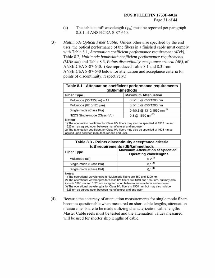
(3) Multimode Optical Fiber Cable. Unless otherwise specified by the end
user, the optical performance of the fibers in a finished cable must comply with Table 8.1, Attenuation coefficient performance requirement (dB/k), Table 8.2, Multimode bandwidth coefficient performance requirements (MHz-km) and Table 8.3, Points discontinuity acceptance criteria (dB), of ANSI/ICEA S-87-640. (See reproduced Table 8.1 and 8.3 from ANSI/ICEA S-87-640 below for attenuation and acceptance criteria for points of discontinuity, respectively.)
Table 8.1 - Attenuation coefficient performance requirements
(dB/km)methods Fiber Type Maximum Attenuation
Multimode (50/125 ⎧m) – All 3.5/1.0 @ 850/1300 nm Multimode (62.5/125 μm) 3.5/1.0 @ 850/1300 nm Single-mode (Class IVa) 0.4/0.3 @ 1310/1550 nm(1) NZDS Single-mode (Class IVd) 0.3 @ 1550 nm(2)
Notes: 1) The attenuation coefficient for Class IVa fibers may also be specified at 1383 nm and 1625 nm as agreed upon between manufacturer and end-user. 2) The attenuation coefficient for Class IVd fibers may also be specified at 1625 nm as agreed upon between manufacturer and end-user.
Table 8.3 - Points discontinuity acceptance criteria
(dB)requirements (dB/km)methods Fiber Type Maximum Attenuation at Specified
Operating Wavelengths Multimode (all) 0.2(1) Single-mode (Class IVa) 0.1(2) Single-mode (Class IVd) 0.1(3)
Notes: 1) The operational wavelengths for Multimode fibers are 850 and 1300 nm. 2) The operational wavelengths for Class IVa fibers are 1310 and 1550 nm, but may also include 1383 nm and 1625 nm as agreed upon between manufacturer and end-user. 3) The operational wavelengths for Class IVd fibers is 1550 nm, but may also include 1625 nm as agreed upon between manufacturer and end-user.
(4) Because the accuracy of attenuation measurements for single mode fibers
becomes questionable when measured on short cable lengths, attenuation measurements are to be made utilizing characterization cable lengths. Master Cable reels must be tested and the attenuation values measured will be used for shorter ship lengths of cable.

RUS BULLETIN 1753F-601a Page 32 of 44
(5) Because the accuracy of attenuation measurements for multimode fibers becomes questionable when measured on short cable lengths, attenuation measurements are to be made utilizing characterization cable lengths. If the ship length of cable is less than one kilometer, the attenuation values measured on longer lengths of cable (characterization length of cable) before cutting to the ship lengths of cable may be applied to the ship lengths.
(6) Attenuation must be measured per Table 8.4, Optical Attenuation
Measurement Methods, of ANSI/ICEA S-87-640. (See reproduced Table 8.4 from ANSI/ICEA S-87-640 below for measurement method.)
Table 8.4 - Optical attenuation measurement methods Fibers Measurement Method Multimode, Graded Index only FOTP-78
Single-mode, Dispersion Unshifted FOTP-78
Single-mode only, Non-zero Dispersion-shifted FOTP-78
(7) The bandwidth of multimode fibers in a finished cable must be no less
than the values specified in ANSI/ICEA S-87-640, Table 8.2 per paragraphs 8.3.1 and 8.3.2. (See reproduced Table 8.2 from ANSI/ICEA S-87-640 below for bandwidth of multimode fibers.)
Table 8.2 - Multimode bandwidth coefficient performance requirements (MHz•km)
Source Conditions
Minimum Modal Bandwidth 50/125 62.5/125
492AAAB 492AAAC OFL 850nm 1300 nm EMB 850 nm
500 500
NA
1500 500
2000
160 500
NA

RUS BULLETIN 1753F-601a Page 33 of 44
r Mechanical Requirements.
Fiber optic cables manufactured under the requirements of this section must be tested by the manufacturer to determine compliance with such requirements. Unless otherwise specified, testing must be performed at the standard conditions defined in paragraph 7.3.1 of ANSI/ICEA S-87-640. (See table below for testing conditions.) The standard optical test wavelengths to be used are 1550 nm single mode and 1300 nm multi-mode, unless otherwise specified in the individual test.
Standard Conditions for Testing per TIA/EIA-455
Condition Standard Ambient Temperature 23 + 5 °CRelative Humidity 20 to 70 %Atmospheric Pressure Site Ambient
(1) Sheath Slitting Cord Test. All cables manufactured under the
requirements of this section must meet the Ripcord Functional Test described in paragraphs 7.18.1 and 7.18.2 of ANSI/ICEA S-87-640.
(2) Material Compatibility and Cable Aging Test. All cables
manufactured under the requirements of this section must meet the Material Compatibility and Cable Aging Test described in paragraphs 7.19 through 7.19.2.4 of ANSI/ICEA S-87-640.
(3) Cable Low and High Bend Test. Cables manufactured under the
requirements of this section must meet the Cable Low (-30°C (-22°F)) and High (60ºC (140ºF)) Temperatures Bend Test per paragraphs 7.21 and 7.21.2 of ANSI/ICEA S-87-640.
(4) Compound Flow Test. All cables manufactured under the
requirements of this section must meet the test described in paragraphs 7.23, 7.23.1, and 7.23.2 of ANSI/ICEA S-87-640.
(5) Cyclic Flexing Test. All cables manufactured under the
requirements of this section must meet the Flex Test described in paragraphs 7.27 through 7.27.2 of the ANSI/ICEA S-87-640.
(6) Water Penetration Test. All cables manufactured under the
requirements of this section must meet paragraphs 7.28 through 7.28.2 of ANSI/ICEA S-87-640.

RUS BULLETIN 1753F-601a Page 34 of 44
(7) Cable Impact Test. All cables manufactured under the requirements of this section must meet the Cable Impact Test described in paragraphs 7.29.1 and 7.29.2 of ANSI/ICEA S-87-640.
(8) Cable Tensile Loading and Fiber Strain Test. Cables
manufactured under the requirements of this section must meet the Cable Loading and Fiber Strain Test described in paragraphs 7.30 through 7.30.2 of ANSI/ICEA S-87-640. This test does not apply to aerial self-supporting cables.
(9) Cable Compression Test. All cables manufactured under
requirements of this section must meet the Cable Compressive Loading Test described in paragraphs 7.31 through 7.31.2 of ANSI/ICEA S-87-640.
(10) Cable Twist Test. All cables manufactured under the requirements
of this section must meet the Cable Twist Test described in paragraphs 7.32 through 7.32.2 of ANSI/ICEA S-87-640.
(11) Cable Lighting Damage Susceptibility Test. Cables manufactured
under the requirements of this section must meet the Cable Lighting Damage Susceptibility Test described in paragraphs 7.33 and 7.33.1 of ANSI/ICEA S-87-640.
(12) Cable External Freezing Test. All cables manufactured under the
requirements of this section must meet the Cable External Freezing Test described in paragraphs 7.22 and 7.22.1 of ANSI/ICEA S-87-640.
(13) Cable Temperature Cycling Test. All cables manufactured under
the requirements of this section must meet the Cable Temperature Cycling Test described in paragraph 7.24.1 of ANSI/ICEA S-87-640.
(14) Cable Sheath Adherence Test. All cables manufactured under the
requirements of this section must meet the Cable Sheath Adherence Test described in paragraphs 7.26.1 and 7.26.2 of ANSI/ICEA S-87-640.

RUS BULLETIN 1753F-601a Page 35 of 44
(15) Mid-Span Test. This test is applicable only to cables of a loose tube design specified for mid-span applications with tube storage. Cable of specialty design may be exempted from this requirement when this requirement is not applicable to such design. All buried and underground loose tube single mode cables manufactured per the requirements in this section and intended for mid-span applications with tube storage must meet the following mid-span test without exhibiting an increase in fiber attenuation greater than 0.1 dB and a maximum average increase over all fibers of 0.05 dB.
(a) The specimen must be installed in a commercially available
pedestal or closure or in a device that mimics their performance, as follows: A length of cable sheath, equal to the mid-span length, must be removed from the middle of the test specimen so as to allow access to the buffer tubes. All binders, tapes, strength members, etc. must be removed. The buffer tubes must be left intact. The cable ends defining the ends of the mid-span length must be properly secured in the closure to the more stringent of the cable or hardware manufacturer's recommendations. Strength members must be secured with an end stop type clamp and the outer jacket must be clamped to prevent slippage. A minimum of 6.096 meters (20 feet) of cable must extend from the entry and exit ports of the closure for the purpose of making optical measurements. If a device that mimics the performance of pedestals or closures is used, the buffer tubes must be wound in a coil with a minimum width of 3 inches and minimum length of 12 inches.
(b) The expressed buffer tubes must be loosely constrained
during the test.
(c) The enclosure, with installed cable, must be placed in an environmental chamber for temperature cycling. It is acceptable for some or all of the two 20 feet (6.096 meters) cable segments to extend outside the environmental chamber.
(d) Lids, pedestal enclosures, or closure covers must be
removed if possible to allow for temperature equilibrium of the buffer tubes. If this is not possible, the manufacture must demonstrate that the buffer tubes are at temperature equilibrium prior to beginning the soak time.

RUS BULLETIN 1753F-601a Page 36 of 44
(e) Measure the attenuation of single mode fibers at 1550 ± 10 nm. The supplier must certify the performance of lower specified wavelengths comply with the mid-span performance requirements.
(f) After measuring the attenuation of the optical fibers, test
the cable sample per TIA/EIA Standard 455-3A. Temperature cycling, measurements, and data reporting must conform to TIA/EIA Standard 455-3A. The test must be conducted for at least five complete cycles. The following detailed test conditions must apply:
A TIA/EIA Standard 455-3A, Section 4.1 – Loose
tube single mode optical cable sample must be tested.
B TIA/EIA Standard 455-3A, Section 4.2 – An
Agency accepted 8 to 12 inch diameter optical buried distribution pedestal or a device that mimics their performance must be tested.
C Mid-span opening for installation of loose tube
single mode optical cable in pedestal must be 6.096 meters (20 feet).
D TIA/EIA Standard 455-3A, Section 5.1 – 3 hours
soak time.
E TIA/EIA Standard 455-3A, Section 5.2 – Test Condition C-2, minimum –40°C (-40°F) and maximum 70° Celsius (158°F).
F TIA/EIA Standard 455-3A, Section 5.7.2 – A
statistically representative amount of transmitting fibers in all express buffer tubes passing through the pedestal and stored must be measured.
G The buffer tubes in the closure or pedestal must not
be handled or moved during temperature cycling or attenuation measurements.

RUS BULLETIN 1753F-601a Page 37 of 44
(g) Fiber cable attenuation measured through the express buffer tubes during the last cycle at -40°C (-40°F) and +70°C (158°F) must not exceed a maximum increase of 0.1 dB and must not exceed a 0.05 dB average across all tested fibers from the initial baseline measurements. At the conclusion of the temperature cycling, the maximum attenuation increase at 23°C from the initial baseline measurement must not exceed 0.05 dB which allows for measurement noise that may be encountered during the test. The cable must also be inspected at room temperature at the conclusion of all measurements; the cable must not show visible evidence of fracture of the buffer tubes nor show any degradation of all exposed cable assemblies.
(16) Aerial Self-Supporting Cables. The following tests apply to aerial
cables only:
(a) Static Tensile Testing of Aerial Self-Supporting Cables. Aerial self-supporting cable must meet the test described in paragraphs D.4.1.1 through D.4.1.5 of ANSI/ICEA S-87-640.
(b) Cable Galloping Test. Aerial self-supporting cable made to
the requirements of this section must meet the test described in paragraphs D.4.2 through D.4.2.3 of ANSI/ICEA S-87-640.
s Pre-connectorized Cable
(1) At the option of the manufacturer and upon request by the end user, the
cable may be factory terminated with connectors.
(2) All connectors must be accepted by the Agency prior to their use. To obtain the Agency's acceptance of connectors, refer to product acceptance procedures available at http://www.usda.gov/rus/telecom/listing_procedures/index_listing_procedures.htm as well as RUS Bulletin 345-3.

RUS BULLETIN 1753F-601a Page 38 of 44
t Acceptance Testing
(1) The tests described in the Appendix to this section are intended for acceptance of cable designs and major modifications of accepted designs. What constitutes a major modification is at the discretion of the Agency. These tests are intended to show the inherent capability of the
manufacturer to produce cable products that have satisfactory performance characteristics, long life, and long-term optical stability but are not intended as field tests. After initial RUS product acceptance is granted, the manufacturer will need to apply for continued product acceptance in January of the third year after the year of initial acceptance. For information on Agency acceptance, refer to the product acceptance procedures available at http://www.usda.gov/rus/telecom/listing_procedures/index_listing_procedures.htm, as well as RUS Bulletin 345-3.
(2) Acceptance. For initial acceptance, the manufacturer must submit:
(a) An original signature certification that the product fully complies
with each paragraph of this section; (b) Qualification Test Data, per the Appendix to this section;
(c) A set of instructions for handling the cable;
(d) OSHA Material Safety Data Sheets for all components;
(e) Agree to periodic plant inspections;
(f) A certification stating whether the cable, as sold to RUS
Telecommunications borrowers, complies with the following two provisions:
(1) Final assembly or manufacture of the product, as the
product would be used by an RUS Telecommunications borrower, is completed in the United States or eligible countries (currently, Mexico, Canada and Israel); and
(2) The cost of United States and eligible countries'
components (in any combination) within the product is more than 50 percent of the total cost of all components utilized in the product. The cost of non-domestic components (components not manufactured within the United States or eligible countries) which are included in the finished product must include all duties, taxes, and delivery charges to the point of assembly or manufacture;

RUS BULLETIN 1753F-601a Page 39 of 44
(g) Written user testimonials concerning performance of the product;
and
(h) Other nonproprietary data deemed necessary.
(3) Re-qualification acceptance. For submission of a request for continued product acceptance after the initial acceptance, follow paragraph 2t(1) and then, in January every three years, the manufacturer must submit an original signature certification stating that the product fully complies with each paragraph of this bulletin, excluding the qualification sections (paragraphs 2t(2), 2t(3) and (2t(4)), and a certification that the products sold to RUS Telecommunications borrowers comply with paragraphs 2t(2)(f) through 2t(2)(f)(B) of this bulletin The tests of the Appendix to this section must be conducted and records kept for at least three years and the data must be made available to the Agency on request. The required data must have been gathered within 90 days of the submission. A certification must be submitted to the Agency stating that the cable manufactured to the requirements of this section has been tested per the Appendix of this section and that the cable meets the test requirements.
(4) Initial and re-qualification acceptance requests should be addressed to:
Chairman, Technical Standards Committee "A" (Telecommunications), STOP 1550, Rural Utilities Service, Advanced Services Division, Telecommunications Program, Washington, DC 20250-1500.
(5) Tests on 100 Percent of Completed Cable.
(a) The armor for each length of cable must be tested for continuity
using the procedures of ASTM D 4566.
(b) Attenuation for each optical fiber in the cable must be measured.
(c) Optical discontinuities greater than 0.1 dB must be isolated and their location and amplitude recorded.
(6) Capability Tests. The manufacturer must establish a quality assurance
system. Tests on a quality assurance basis must be made as frequently as is required for each manufacturer to determine and maintain compliance with all the mechanical requirements and the fiber and cable attributes required by this section, including:
(a) Numerical aperture and bandwidth of multimode fibers;
(b) Cut off wavelength of single mode fibers;

RUS BULLETIN 1753F-601a Page 40 of 44
(c) Dispersion of single mode fibers;
(d) Shrinkback and cold testing of loose tube and tight tube buffers, and mid-span testing of cables of a loose tube design with tube storage;
(e) Adhesion properties of the protective fiber coating;
(f) Dielectric strength between the armor and the metallic central
member;
(g) Performance requirements for the fibers;
(h) Performance requirements for the inner and outer jacketing materials;
(i) Performance requirements for the filling and flooding compounds;
(j) Bonding properties of the coated armoring material;
(k) Sequential marking and lettering; and
(l) Mechanical tests described in paragraphs 2r(1) through 2r(16)(b)
of this bulletin.
u Records Tests
(1) Each manufacturer must maintain suitable summary records for a period of at least 3 years of all optical and physical tests required on completed cable by section as set forth in paragraphs 2t(5) and 2t(6) of this bulletin. The test data for a particular reel must be in a form that it may be readily available to the Agency upon request. The optical data must be furnished to the end user on a suitable and easily readable form.
(2) Measurements and computed values must be rounded off to the number of
places or figures specified for the requirement per paragraph 1.3 of ANSI/ICEA S-87-640.
v Manufacturing Irregularities
(1) Under this section, repairs to the armor, when present, are not permitted in
cable supplied to the end user.
(2) Minor defects in the inner and outer jacket (defects having a dimension of 3 millimeter or less in any direction) may be repaired by means of heat fusing per good commercial practices utilizing sheath grade compounds.

RUS BULLETIN 1753F-601a Page 41 of 44
w Packaging and Preparation for Shipment
(1) The cable must be shipped on reels containing one continuous length of cable. The diameter of the drum must be large enough to prevent damage to the cable from reeling and unreeling. The diameter must be at least equal to the minimum bending diameter of the cable. The reels must be substantial and so constructed as to prevent damage during shipment and handling.
(2) A circumferential thermal wrap or other means of protection must be
secured between the outer edges of the reel flange to protect the cable against damage during storage and shipment. The thermal wrap must meet the requirements included in the Thermal Reel Wrap Test, described below. This test procedure is for qualification of initial and subsequent changes in thermal reel wraps.
(a) Sample Selection. All testing must be performed on two 450
millimeter (18 inches) lengths of cable removed sequentially from the same fiber jacketed cable. This cable must not have been exposed to temperatures in excess of 38°C (100°F) since its initial cool down after sheathing.
(b) Test Procedure:
(1) Place the two samples on an insulating material such as
wood.
(2) Tape thermocouples to the jackets of each sample to measure the jacket temperature.
(3) Cover one sample with the thermal reel wrap.
(4) Expose the samples to a radiant heat source capable of
heating the uncovered sample to a minimum of 71°C (160 °F). A GE 600 watt photoflood lamp or an equivalent lamp having the light spectrum approximately that of the sun must be used.
(5) The height of the lamp above the jacket must be 380
millimeters (15 inches) or an equivalent height that produces the 71°C (160 °F) jacket temperature on the unwrapped sample must be used.

RUS BULLETIN 1753F-601a Page 42 of 44
(6) After the samples have stabilized at the temperature, the jacket temperatures of the samples must be recorded after one hour of exposure to the heat source.
(7) Compute the temperature difference between jackets.
(8) The temperature difference between the jacket with the
thermal reel wrap and the jacket without the reel wrap must be greater than or equal to 17°C (63 °F).
(3) Cables must be sealed at the ends to prevent entrance of moisture.
(4) The end-of-pull (outer end) of the cable must be securely fastened to
prevent the cable from coming loose during transit. The start-of-pull (inner end) of the cable must project through a slot in the flange of the reel, around an inner riser, or into a recess on the flange near the drum and fastened in such a way to prevent the cable from becoming loose during installation.
(5) Spikes, staples or other fastening devices must be used in a manner which
will not result in penetration of the cable.
(6) The arbor hole must admit a spindle 63.5 millimeters (2.5 inches) in diameter without binding.
(7) Each reel must be plainly marked to indicate the direction in which it
should be rolled to prevent loosening of the cable on the reel.
(8) Each reel must be stenciled or lettered with the name of the manufacturer.

RUS BULLETIN 1753F-601a Page 43 of 44
(9) The following information must be either stenciled on the reel or on a tag firmly attached to the reel:
OPTICAL CABLE
Type and Number of Fibers Armored or Non-armored
Year of Manufacture Name of Cable Manufacturer
Length of Cable Reel Number
7 CFR 1755.902 Minimum Bending Diameter for both Residual
and Loaded Condition during installation Example:
OPTICAL CABLE G.657 class A, 4 fibers
Armored XYZ Company
1050 meters Reel Number 3
7 CFR 1755.902 Minimum Bending Diameter:
Residual (Installed): 20 times Cable O.D Loaded Condition: 40 times Cable O.D

RUS BULLETIN 1753F-601a Page 44 of 44
APPENDIX TO RUS Bulletin 1753F-601a
FIBER OPTIC CABLES
Bulletin 1753F-601a (PE-90) Qualifications Test Data Initial qualification and three year re-qualification test data required for TELECOMMUNICATIONS PROGRAM product acceptance. Please note that some tests may apply only to a particular cable design.
Paragraph
Test
Initial Qualification
3 Year Re-qualification
2c(4)(a) Shrinkback X 2c(4)(b) Cold Bend X 2r(1) Sheath Slitting Cord X 2r(2) Material Compatibility X 2r(3) Cable Low & High Bend X X 2r(4) Compound Flow X 2r(5) Cyclic Flexing X X 2r(6) Water Penetration X X 2r(7) Cable Impact X X
2r(8) Cable Tensile Loading & Fiber Strain X X
2r(9) Cable Compression X 2r(10) Cable Twist X X
2r(11) Cable Lighting Damage Susceptibility X
2r(12) Cable External Freezing X 2r(13) Cable Temperature Cycling X X 2r(14) Cable Sheath Adherence X 2r(15) Mid-Span X X
2r(16)(a) Static Tensile Testing of Aerial Self-Supporting Cables X X
2r(16)(b) Cable Galloping X 2y(2) Thermal Reel Wrap X