BF75A/90A Owner's Manual
149
© HONDA MOTOR CO., LTD. 1995 BF75A/90A Owner’s Manual
Transcript of BF75A/90A Owner's Manual
© HONDA MOTOR CO., LTD. 199531ZW060200X31-ZW0-6020
200.2002.05PRINTED IN U.S.A.
BF75A/90AOwner’sManual
EM

The engine exhaust from this product
Thank you for purchasing a Honda Outboard Motor.
This manual describes the operation and maintenance of the Honda BF 75A and BF 90A Outboard Motors.
All information in this publication is based on the latest product informa- tion available at the time of printing. Honda Motor Co., Ltd. reserves the right to make changes at any time without notice and without incurring any obligation.
No part of this publication may be reproduced without written permission.
This manual should be considered a permanent part of the Outboard Motor and it must stay with the Outboard Motor if resold.
SAFETY MESSAGES
Your safety and the safety of others are very important. We have provided important safety messages in this manual and on the outboard motor. Please read these messages carefully.
A safety message alerts you to poten- tial hazards that can hurt you and others. Each safety message is preceded by a safety alert symbol A and one of three words: DANGER, WARNING, or CAUTION.
These mean:
B You WILL be KILLED or SERIOUSLY HURT if you don’t follow instructions.
- You CAN be KILLED or SERIOUSLY HURT if you don’t follow instructions.
- You CAN be HURT if you don’t follow instructions.
Each message tells you what the hazard is, what can happen, and what you can do to avoid or reduce injury.
DAMAGE PREVENTION
MESSAGES
You will also see other important messages that are preceded by the word NOTICE.
This word means:
NOTICE Your outboard motor
or other property can be damaged if you don’t follow instructions.
The purpose of these messages is to help prevent damage to your outboard motor, other property, or the environment.
HONDA MOTOR CO., LTD. 1995 ALL RIGHTS RESERVED
1
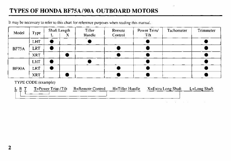
TYPES OF HONDA BF75AIBOA OUTBOARD MOTORS
It may be necessary to refer to this chart for reference purposes when reading this manual.
TYPE CODE (example)
LRT T=Power Trim /Tilt R=Remote Control H=Tiller Handle X=Extra Long Shaft L=Long Shaft TT,
2
IDENTIFICATION NUMBERS
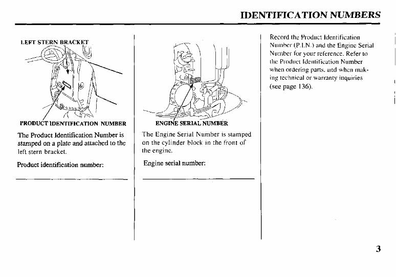
LEFTSTERNBRACKET
PRODUdT IDENTIFICATION NUMBER
The Product Identification Number is stamped on a plate and attached to the left stern bracket.
Product identification number:
ENGIN’E SERIAL NUMBER
The Engine Serial Number is stamped on the cylinder block in the front of the engine.
Engine serial number:
Record the Product Identification Number (P.I.N.) and the Engine Serial Number for your reference. Refer to the Product Identification Number when ordering parts, and when mak- ing technical or warranty inquiries (see page 136).
CONTENTS
1. SAFETY SAFETY LABELS.. ................... SAFETY INFORMATION.. ......
2. COMPONENT IDENTIFICATION ... 3. CONTROLS & INSTRUMENTS
TILLER HANDLE TYPE Ignition Switch ........................... Gear Shift Lever.. ....................... Choke Knob ................................ Throttle Grip.. ............................. Throttle Opening Indicator.. ....... Throttle Friction Knob ............... Engine Stop Switch .................... Emergency Stop Switch Lanyard . . Oil Pressure Indicator Light ....... Overheat indicator Light ............ Power Trim/Tilt Switch.. ............ Steering Friction Adjuster ..........
REMOTE CONTROL TYPE (SIDE-MOUNT TYPE)
Remote Control Lever.. .............. Neutral Release Lever ................ Ignition Switch ........................... Emergency Stop Switch Lanyard . . Choke/Fast Idle Lever ................ Manual Choke Knob .................. Oil Pressure Indicator Light/Buzzer .... Overheat Indicator Light/Buzzer ... Power Trim/Tilt Switch.. ............
4
6 7 8
14 I4 I4 I5 I5 15 16 I6 17 I7 18 18
I9 20 20
;: 22 23 23 24
(PANEL-MOUNT TYPE) Remote Control Lever.. .............. 25 Nertral Release Lever.. ............... 26 Ignition Switch ........................... 26 Emergency Stop Switch Lanyard 27 Throttle Button ........................... 28 Choke Switch ............................. 28 Manual Choke Knob .................. 28 Oil Pressure Indicator Light/Buzzer .... 29 Overheat Indicator Light/Buzzer.. .... 29 Power Trim/Tilt Switch.. ............ 30
(TOP-MOUNT TYPE) Remote Control Lcvcr ................ 3 I Ignition Switch ........................... 32 Emergency Stop Switch Lanyard 33 Throttle Button ........................... 34 Choke Switch ............................. 34 Manual Choke Knob .................. 34 Oil Pressure Indicator Light/Buzzer .... 35 Overheat Indicator Light/Buzzer.. . 35 Power Trim/Tilt Switch
(remote control lever). . 36 Power Trim/Tilt Switch
(control box console). .. 36 COMMON
Power Tilt Switch (engine pan). . 37 Trim Meter.. ...................................... 37 Tachometer (optional equipment) . . 37 Manual Relief Valve .................. 38 Tilt Lock Lever.. ......................... 39
Trim Tab . . . . . . . . . . . . . . . . . . . . . . . . . . . . . . . . . . . . . 39 Anode Metal . . . . . . . . . . . . . . . . . . . . . . . . . . . . . . . 40 Cooling System Indicator . . . . . . . . . . . 40 Water Intakes . . . . . . . . . . . . . . . . . . . . . . . . . . . . . . 40 Transom Angle Adjusting Rod . . 41 Fuel Cap/Gauge/Vent Knob
(optional fuel tank) . . 42 Over-Rev Limiter . . . . . . . . . . . . . . . . . . . . . . . 42 Engine Cover Lock Lever . . . . . . . . . . 43 Fuel Host Connector . . . . . . . . . . . . . . . . . . 43
4. PRE-OPERATION CHECKS Engine Cover Removal/Installation . . 44 Engine Oil ..,............................... 45 Fuel Level (optional fuel tank) . . . 46 Fuel Recommendations . . . . . . . . . . . . . . 47 Oxygenated Fuels . . . . . . . . . . . . . . . . . . . . . . . 48 Propeller and Cotter Pin Inspection . . 49 Steering Friction Adjustment
(TILLER HANDLE TYPE) . . 50 Remote Control Friction Adjustment . . . . . . . . . . . . . . . . . . . . . . . . . . . . . . . . . 50 Engine Cover Lock Lever
Adjustment . . 51 Other Checks l Stem bracket . . . . . . . . . . . . . . . . . . . . . . . . . . . . 52 l Tool Kit . . . . . . . . . . . . . . . . . . . . . . . . . . . . . . . . . . . . 52 l Anodes ,........,.......................,,.. 52
5. STARTlNG THE ENGINE Optional Fuel Tank . . . . . . . . . . . . . . . . . . . . . 53 Fuel Line Connection . . . . . . . . . . . . . . . . . 53
CONTENTS
STARTING THE ENGINE (TILLER HANDLE TYPE) . . . . 55
STARTING THE ENGINE (REMOTE CONTROL TYPE) . . . 60
(SIDE-MOUNT TYPE) . . . . . . . . . . 60 (PANEL-MOUNT TYPE) . . . . . . 63 (TOP-MOUNT TYPE) . . . . . . . . . . . . 66
STARTING THE ENGINE (EMERGENCY STARTING). 69
Troubleshooting Starting Problems . . 74 6. OPERATION
Break-in Procedure . . . . . . . . . . . . . . . . . . . . . 75 TILLER HANDLE TYPE
Gear Shifting . . . . . . . . . . . . . . . . . . . . . . . . . . . 76 Steering . . . . . . . . . . . . . . . . . . . . . . . . . . . . . . . . . . . . 76 Cruising . . . . . . . . . . . . . . . . . . . . . . . . . . . . . . . . . . . 77
REMOTE CONTROL TYPE (SIDE-MOUNT TYPE)
Gear Shifting . . . . . . . . . . . . . . . . . . . . . . . . . . . 78 Cruising . . . . . . . . . . . . . . . . . . . . . . . . . . . . . . . . . . . 79
(PANEL-MOUNT TYPE) Gear Shifting . . . . . . . . . . . . . . . . . . . . . . . . . . . 80 Cruising . . . . . . . . . . . . . . . . . . . . . . . . . . . . . . . . . . . 81
(TOP-MOUNT TYPE) Gear Shifting . . . . . . . . . . . . . . . . . . . . . . . . . . . 82 Cruising . . . . . . . . . . . . . . . . . . . . . . . . . . . . . . . . . . . 83
POWER TRIM/TILT Power Trim/Tilt System . . . . . . . . 84 Trim Meter . . . . . . . . . . . . . . . . . . . . . . . . . . . . . . 86 Power Tilt Switch (engine pan) . . . 87
Manual Relief Valve ............... 87 Tilt Lock Lever.. ...................... 88
Trim Tab Adjustment .................. 89 MOTOR PROTECTION SYSTEM
Engine Oil Pressure and Overheat Warning System ...... 90 Over-Rev Limiter .................... 92 Anodes ..................................... 92
Shallow Water Operation ........... 93 High Altitude Operation ............. 94
7. STOPPING THE ENGINE TILLER HANDLE TYPE.. ........ 95 REMOTE CONTROL TYPE (SIDE-MOUNT TYPE) ............. 96 (PANEL-MOUNT TYPE) ......... 97 (TOP-MOUNT TYPE) ............... 98
8. TRANSPORTING ...................... 99 9. CLEANING AND FLUSHING . 102
IO. MAINTENANCE ....................... 104 THE IMPORTANCE OF
MAINTENANCE .................... I04 MAINTENANCE SAFETY ....... 104 EMISSION CONTROL
SYSTEM INFORMATION.. .. 105 Tool Kit and Spare Parts ............ 108 MAINTENANCE SCHEDULE.. .. 109
Engine Oil ............................... 1 11 Gear Oil ................................... 113 Spark Plugs .............................. 115 Battery (not included) .............. 1 16
Lubrication .............................. 1 18 Engine Fuel Filter.. .................. 12 1 Fuel Tank and Filter ................ 123 Fuse Replacement ................... 124 Propeller .................................. 125 Submerged Motor.. .................. 126
11. STORAGE.. ................................ 128 12. TROUBLESHOOTING ............. 132 13. SPECIFICATIONS .................... 134 14. WARRANTY SERVICE ........... 136 15.INDEX.. ...................................... 137 16. WIRING DIAGRAM ................. 14 1
5
1. SAFETY
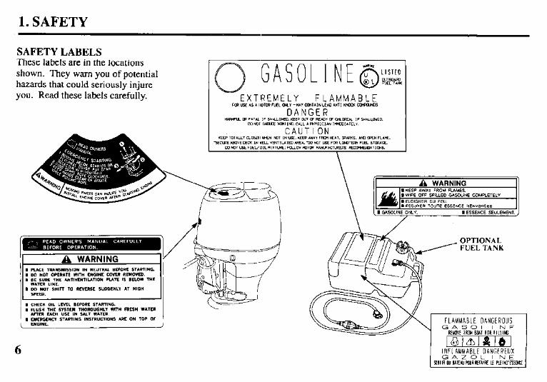
SAFETYLABELS These labels are in the locations shown. They warn you of potential hazards that could seriously injure you. Read these labels carefully.
FUEL TANK
1. SAFETY
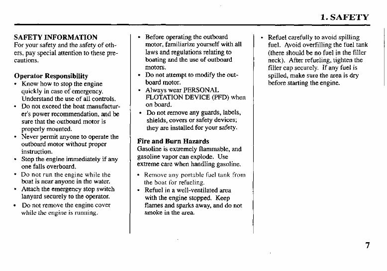
SAFETY INFORMATION For your safety and the safety of oth- ers, pay special attention to these pre- cautions.
Operator Responsibility l Know how to stop the engine
quickly in case of emergency. Understand the use of all controls.
l Do not exceed the boat manufactur- er’s power recommendation, and be sure that the outboard motor is properly mounted.
l Never permit anyone to operate the outboard motor without proper instruction.
l Stop the engine immediately if any one falls overboard.
l Do not run the engine while the boat is near anyone in the water.
l Attach the emergency stop switch lanyard securely to the operator.
l Do not remove the engine cover while the engine is running.
l Before operating the outboard motor, familiarize yourself with all laws and regulations relating to boating and the use of outboard motors.
l Do not attempt to modify the out- board motor.
l Always wear PERSONAL FLOTAmON DEVICE (PFD) when on board.
l Do not remove any guards, labels, shields, covers or safety devices; they are installed for your safety.
Fire and Burn Hazards Gasoline is extremely flammable, and gasoline vapor can explode. Use extreme care when handling gasoline.
l Remove any portable fuel tank from the boat for refueling.
l Refuel in a well-ventilated area with the engine stopped. Keep flames and sparks away, and do not smoke in the area.
l Refuel carefully to avoid spilling fuel. Avoid overfilling the fuel tank (there should be no fuel in the filler neck). After refueling, tighten the filler cap securely. If any fuel is spilled, make sure the area is dry before starting the engine.

2. COMPONENT IDENTIFICATION (TILLER HANDLE TYPE)
THROTTLE GRIP
POWER TILT ENGINE COVER LOCK LEVER
L HOSE CONNECTOR
HROTTLE FRICTION KNOB
WASH PLUG
VALVE ENGINE OIL DRAIN BOLT HIFT LEVER ACCESS COV
‘I-VENTILATION NITION SWITCH ANODE METAL
TRANSOM ANG ADJUSTING RO
NODE METAL
/ GEAR OIL REAR VENT DRAIN PLUG \
PLUG EXHAUST PORT \ WATER INTAKE
8
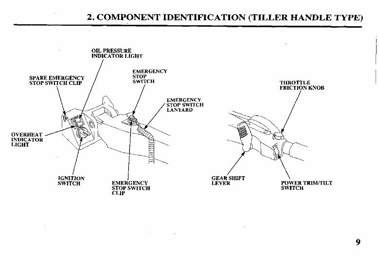
2. COMPONENT IDENTIFICATION (TILLER HANDLE TYPE)
OIL PRESSURE INDICATOR LIGHT
I
SPARE EMERGENCY STOP SWITCH CLIP
\
EMERGENCY STOP SWITCH
IGNIilON SWITCH
I EMERGENCY STOP SWITCH CLIP
THROTTLE FRICTION KNOB
LEVER POWER TRIM/TILT SWITCH
9
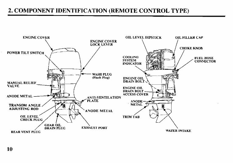
2. COMPONENT IDENTIFICATION (REMOTE CONTROL TYPE)
ENGINE COVER
\ ENGINE COVER LOCK LEVF:R
POWER TILT SWITCH
WASH PLUG
yfr;EAL RELIEF
ANODE METAL ANTI-VENTILATION
TRANSOM ANGLE ADJUSTING ROD
ANODE METAL
CHECK PLU
REAR VENT PLUG
OIL LEVEL DIPSTICK
\
OIL FILLER CAP
ENGINE OIL DRAIN BOLT ACCESS COV
WATER INTAKE
10
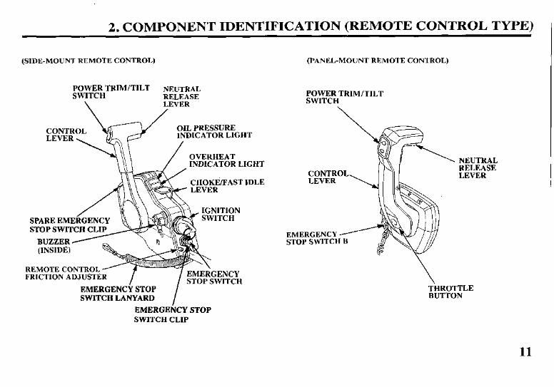
2. COMPONENT IDENTIFICATION (REMOTE CONTROL TYPE1
(SIDE-MOUNT REMOTE CONTROL)
POWER TRIM/TILT NEUTRAL SWITCH RELEASE
\ LEVER
OVERHEAT INDICATOR LIGHT
(INSIDE)
REMOTE CONTROL FRICTION ADJUSTE NLY
ITCH
SWITCH LANYARD I
EMERGENCY STOP SWITCH CLIP
(PANEL-MOUNT REMOTE CONTROL)
POWER TRIM/TILT SWITCH
EMERGENCY STOP SWITCH B
11
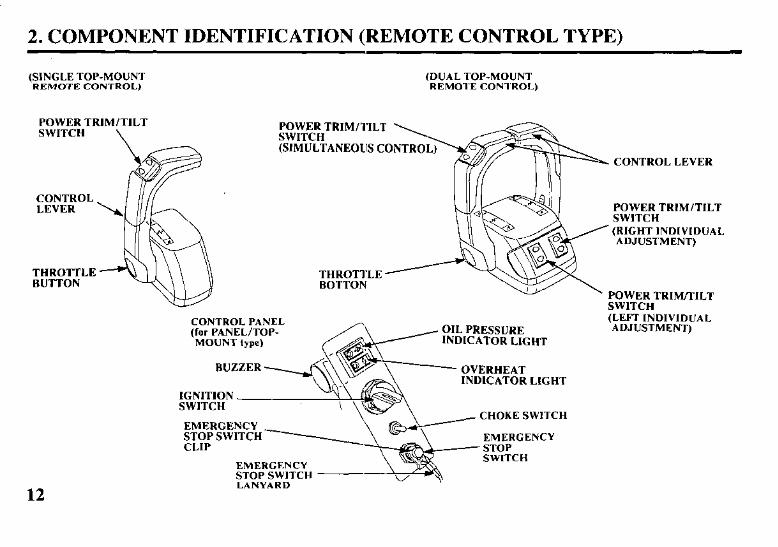
2. COMPONENT IDENTIFICATION (REMOTE CONTROL TYPE)
(SINGLE TOP-MOUN’I (DUAL TOP-MOUNT REMOTE CONTROL) REMOTE CONTROL)
POWER TRIM/TILT SWITCH \
12
CONTROL PANEL (for PANEL/TOP- MOUNT type)
IGNITION SWITCH
EMERGENCY
&-g&H
. CONTROL LEVER
POWER TRIM/TILT SWITCH (RIGHT INDIVIDUAL ADJUSTMENT)
POWER TRIWILT SWITCH (LEFT INDIVIDUAL ADJUSTMENT)
2. COMPONENT IDENTIFICATION (COMMON)
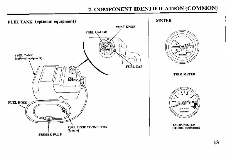
FUEL TANK (optional equipment) VENT KNOB
FUEL G\AUGE /
FUEL TANK (optional equipment)
FUEL
I FUEL HOSE CONNECTOR (female)
PRIMER BULB
METER
TRIM METER
TACHOMETER (optional equipment)
13
3. CONTROLS (TILLER HANDLE TYPE)
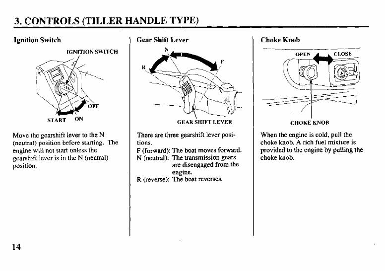
Ignition Switch
IGNITION SWITCH
START ON
Move the gearshift lever to the N (neutral) position before starting. The engine will not start unless the gearshift lever is in the N (neutral) position.
Gear Shift Lever
GEAR SHIFT LEVER CHOKE KNOB
There are three gearshift lever posi- tions. F (forward): The boat moves forward. N (neutral): The transmission gears
are disengaged from the engine.
When the engine is cold, pull the choke knob. A rich fuel mixture is provided to the engine by pulling the choke knob.
R (reverse): The boat reverses.
Choke Knob
14
3. CONTROLS (TILLER HANDLE TYPE)
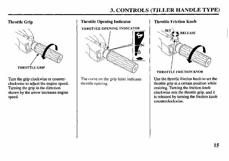
Throttle Grip
THROTTLE GRIP
Turn the grip clockwise or counter- clockwise to adjust the engine speed. Turning the grip in the direction shown by the arrow increases engine speed.
Throttle Opening Indicator
THROTTLE OPENING INDICATOR
The curve on the grip label indicates throttle opening.
Throttle Friction Knob
THROTTtE FRICTION KNOB
Use the throttle friction knob to set the throttle grip at a certain position while cruising. Turning the friction knob clockwise sets the throttle grip, and it is released by turning the friction knob counterclockwise.
15
I 3. CONTROLS (TILLER HANDLE TYPE)
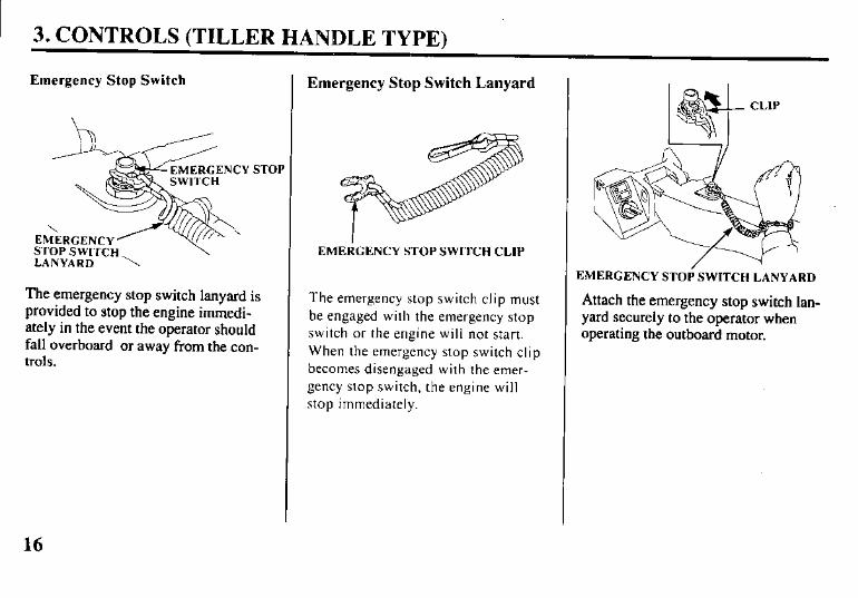
Emergency Stop Switch
ST0
STOP SWITCH \ LANYARD \
The emergency stop switch lanyard is provided to stop the engine immedi- ately in the event the operator should fall overboard or away from the con- trols.
Emergency Stop Switch Lanyard
EMEdGENCY STOP SWITCH CLIP
The emergency stop switch clip must be engaged with the emergency stop switch or the engine will not start. When the emergency stop switch clip becomes disengaged with the emer- gency stop switch, the engine will stop immediately.
EMERGENCY STOI; SWITCH LANYARD
Attach the emergency stop switch lan- yard securely to the operator when operating the outboard motor.
16
3. CONTROLS (TILLER HANDLE TYPE)
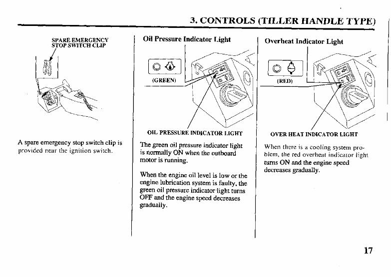
SPARE EMERGENCY STOP SWITCH CLIP
A spare emergency stop switch clip is provided near the ignition switch.
Oil Pressure Indicator Light
OIL PRESSURE INDICATOR LIGHT
The green oil pressure indicator light is normally ON when the outboard motor is running.
When the engine oil level is low or the engine lubrication system is faulty, the green oil pressure indicator ,light turns OFF and the engine speed decreases gradually.
Overheat Indicator Light
OVER HEAT INDICATOR LIGHT
When there is a cooling system pro- blem, the red overheat indicator light turns ON and the engine speed decreases gradually.
17
3. CONTROLS (TILLER HANDLE TYPE)
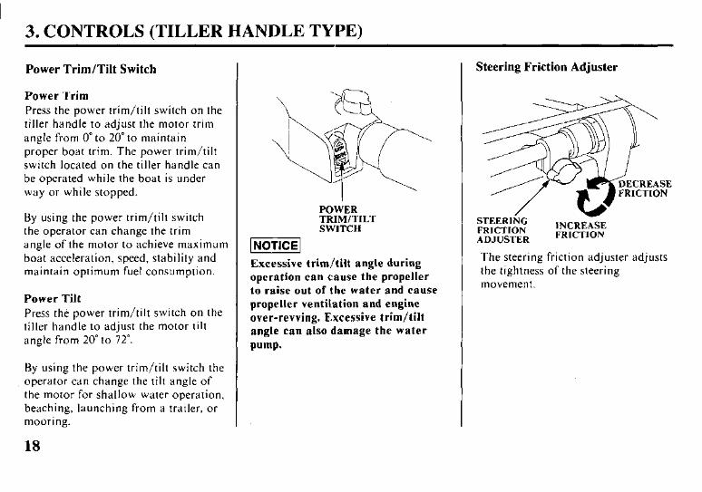
Power Trim/Tilt Switch
Power Trim
Press the power trim/tilt switch on the tiller handle to adjust the motor trim angle from 0” to 20” to maintain proper boat trim. The power trim/tilt switch located on the tiller handle can be operated while the boat is under way or while stopped.
By using the power trim/tilt switch the operator can change the trim angle of the motor to achieve maximum boat acceleration, speed, stability and maintain optimum fuel consumption.
Power Tilt
Press the power trim/tilt switch on the tiller handle to adjust the motor tilt angle from 20” to 72”.
By using the power trim/tilt switch the operator can change the tilt angle of the motor for shallow water operation, beaching, launching from a trailer, or mooring.
18
POWER TRIM/TILT SWITCH
Excessive trim/tilt angle during
operation can cause the propeller
to raise out of the water and cause
propeller ventilation and engine
over-revving. Excessive trim/tilt
angle can also damage the water
pump.
Steering Friction Adjuster
The steering friction adjuster adjusts the tightness of the steering movement.
3. CONTROLS (REMOTE CONTROL TYPE)
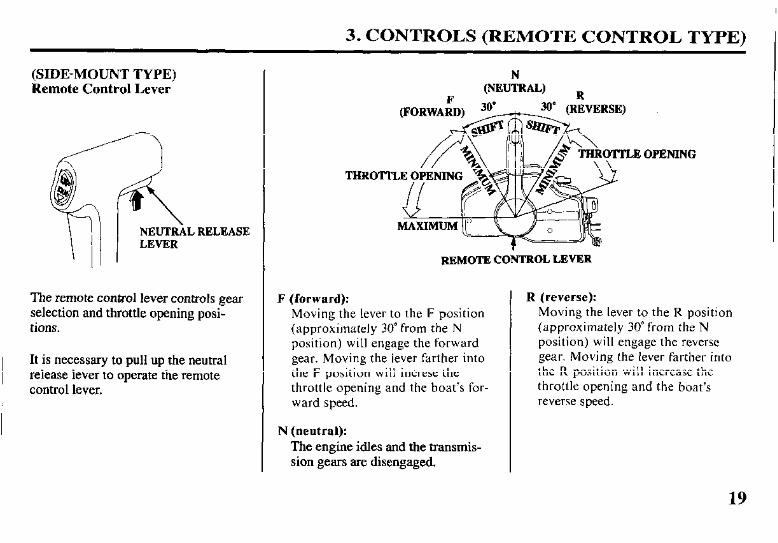
(SIDE-MOUNT TYPE) Remote Control Lever
NEUTRAL RELEASE
The remote control lever controls gear selection and throttle opening posi- tions.
It is necessary to pull up the neutral release lever to operate the remote control lever.
THROTTLE OPENlN
REMOTE CONTROL LEYER
F (forward):
Moving the lever to the F position (approximately 30” from the N position) will engage the forward gear. Moving the lever farther into the F position will increse the throttle opening and the boat’s for- ward speed.
N (neutral):
The engine idles and the transmis- sion gears are disengaged.
OPENING
R (reverse):
Moving the lever to the R position (approximately 30” from the N position) will engage the reverse gear. Moving the lever farther into the R position will increase the throttle opening and the boat’s reverse speed.
19
3. CONTROLS (REMOTE CONTROL TYPE)
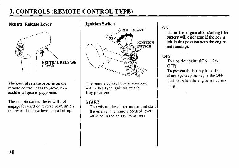
Neutral Release Lever
The neutral release lever is on the remote control lever to prevent an accidental gear engagement.
The remote control lever will not engage forward or reverse gear. unless the neutral release lever is pulled up.
Ignition Switch
The remote control box is equipped with a key-type ignition switch. Key positions:
START
To activate the starter motor and start the engine (the remote control lever must be in the neutral position).
ON
To run the engine after starting (the battery will discharge if the key is left in this position with the engine not running).
OFF To stop the engine (IGNITION OFF). To prevent the battery from dis- charging, keep the key in the OFF position when the engine is not run- ning.
20
3. CONTROLS (REMOTE CONTROL TYPE)
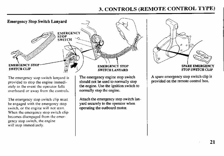
Emergency Stop Switch Lanyard
EMERGENCY
SWITCH CLIP Y SWITCH LANYARD
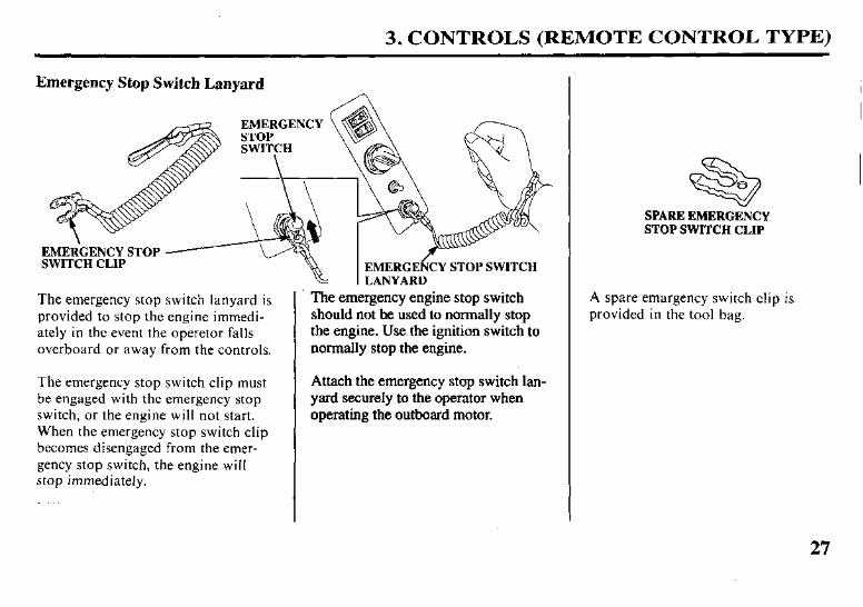
The emergency stop switch lanyard is provided to stop the engine immedi- ately in the event the operator falls overboard or away from the controls.
The emergency stop switch clip must be engaged with the emergency stop switch, or the engine will not start. When the emergency stop switch clip becomes disengaged from the emer- gency stop switch, the engine will stop immediately.
The emergency engine stop switch should not he used to normally stop the engine. Use the ignition switch to normally stop the engine.
Attach the emergency stop switch lan- yard securely to the operator when operating the outboard motor.
SPAkE EMERGENCY STOP SWITCH CLIP
A spare emergency stop switch clip is provided on the remote control box.
21
3. CONTROLS (REMOTE CONTROL TYPE)
Choke/Fast Idle Lever
/+MAXIMUM FAST IDLE
OWEST POSITION
CHOKE/FAST
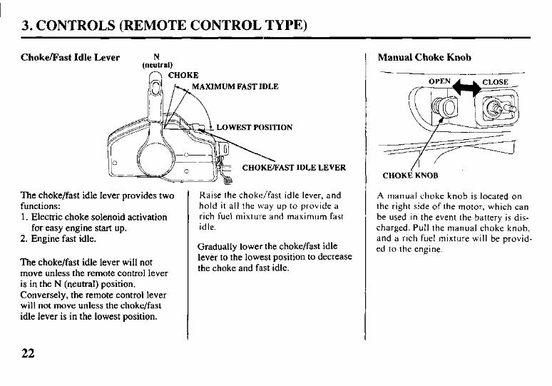
The choke/fast idle lever provides two functions: 1. Electric choke solenoid activation
for easy engine start up. 2. Engine fast idle.
The choke/fast idle lever will not move unless the remote control lever is in the N (neutral) position. Conversely, the remote control lever will not move unless the choke/fast idle lever is in the lowest position.
IDLE LEVER
Raise the choke/fast idle lever, and hold it all the way up to provide a rich fuel mixture and maximum fast idle.
Gradually lower the choke/fast idle lever to the lowest position to decrease the choke and fast idle.
Manual Choke Knob
CHOKE KNOB
A manual choke knob is located on the right side of the motor, which can be used in the event the battery is dis- charged. Pull the manual choke knob, and a rich fuel mixture will be provid- ed to the engine.
22

3. CONTROLS (REMOTE CONTROL TYPE)
Oil Pressure Indicator Light/Buzzer
The green oil pressure indicator light turns OFF and the buzzer sounds when the oil level is low and/or the engine lubrication system is faulty. The engine speed slows down gradual- lY*
Overheat Indicator Light/Buzzer
The red overheat indicator light turns ON and the buzzer sounds when there is a cooling system problem. The engine speed slows down gradually.
23

3. CONTROLS (REMOTE CONTROL TYPE)
Power ‘Rim/Tilt Switch
Power Trim Press the power trim/tilt switch on the remote control to adjust the motor trim angle from 0” to 20” to maintain proper boat trim. The power trim/tilt switch located on the remote control lever can be operated while the boat is under way or while stopped.
By using the power trim/tilt switch, the operator can change the trim angle of the motor to achieve maximum boat acceleration, speed, stability and maintain optimum fuel consumption.
TRIM ANGLE
Power Tilt Press the power trim/tilt swich on the remote control lever to adjust the motor tilt angle from 20” to 72”.
By using the power trim/tilt switch, the operator can change the tilt angle of the motor for shallow water opera- tion, beaching, launching from a trailer, or mooring.
CONTROL LEVER
(NOTICE] Excessive trim/tilt angle during
operation can cause the propeller
to raise out of the water and cause
propeller ventilation and engine
over-revving. Excessive trim/tilt
angle can also damage the water
pump.
24
3. CONTROLS (REMOTE CONTROL TYPE)
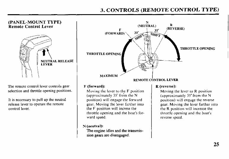
(PANEL-MOUNT TYPE) Remote Control Lever
AL RELEASE
The remote control lever controls gear selection and throttle opening positions.
It is necessary to pull up the neutral release lever to operate the remote control lever.
THROTTLE OPENING THROTTLE OPENING
F (forward): Moving the lever to the F position (approximately 35” from the N position) will engage the forward gear. Moving the lever farther into the F position will increse the throttle opening and the boat’s for- ward speed.
N (neutral): The engine idles and the transmis- sion gears are disengaged.
MAXIMUM ’ I REMOTE CONTROL LEVER
R (reverse): Moving the lever to R position (approximately 35” from the N position) will engage the reverse gear. Moving the lever farther into the R position will increase the throttle opening and the boat’s reverse speed.
25
3. CONTROLS (REMOTE CONTROL TYPE)
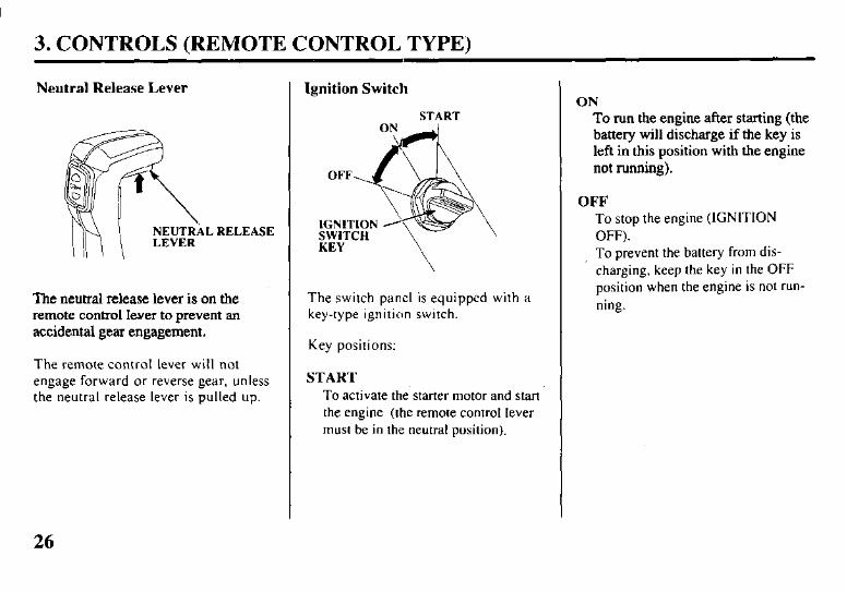
Neutral Release Lever
NEUTRAL RELEASE LEVER
The neutral release lever is on the remote control lwer to prevent an accidental gear engagement.
The remote control lever will not engage forward or reverse gear, unless the neutral release lever is pulled up.
Ignition Switch
START
The switch panel is equipped with a key-type ignition switch.
Key positions:
START To activate the starter motor and start the engine (the remote control lever must be in the neutral position).
ON To run the engine after starting (the battery will discharge if the key is left in this position with the engine not running).
OFF To stop the engine (IGNITION OFF). To prevent the battery from dis- charging, keep the key in the OFF position when the engine is not run- ning.
26
3. CONTROLS (REMOTE CONTROL TYPE)
Emergency Stop Switch Lanyard
EMERGENCY STOP SWITCH
The emergency stop switch lanyard is The emergency engine stop switch provided to stop the engine immedi- should not he used to normally stop ately in the event the operetor falls the engine. Use the ignition switch to overboard or away from the controls. normally stop the engine.
The emergency stop switch clip must be engaged with the emergency stop switch, or the engine will not start. When the emergency stop switch clip becomes disengaged from the emer- gency stop switch, the engine will stop immediately.
Attach the emergency stop switch lan- yard securely to the operator when operating the outboard motor.
EMERGEkCY STOP SWITCH LANYARD
SPARE EMERGENCY STOP SWITCH CLIP
A spare emargency switch clip is provided in the tool bag.
27
3. CONTROLS (REMOTE CONTROL TYPE)
Throttle Button N
(Neutral) l ..**ljsckword
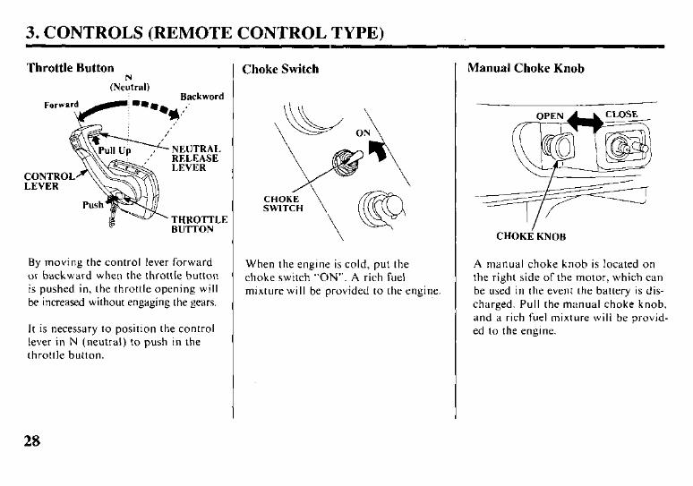
By moving the control lever forward or backward when the throttle button is pushed in, the throttle opening will be increased without engaging the gears.
It is necessary to position the control lever in N (neutral) to push in the throttle button.
Choke Switch
When the engine is cold, put the choke switch “ON”. A rich fuel mixture will be provided to the engine.
Manual Choke Knob
CHOKi KNOB
A manual choke knob is located on the right side of the motor, which can be used in the event the battery is dis- charged. Pull the manual choke knob, and a rich fuel mixture will be provid- ed to the engine.
28
3. CONTROLS (REMOTE CONTROL TYPE)
Oil Pressure Indicator Light/Buzzer
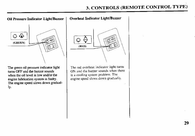
The green oil pressure indicator light turns OFF and the buzzer sounds when the oil level is low and/or the engine lubrication system is faulty. The engine speed slows down gradual- ly*
Overheat Indicator Light/Buzzer
The red overheat indicator light turns ON and the buzzer sounds when there is a cooling system problem. The engine speed slows down gradually.
29
3. CONTROLS (REMOTE CONTROL:)
Power lkim/Tilt Switch
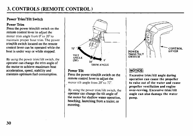
Power Trim Press the power trim/tilt switch on the remote control lever to adjust the motor trim angle from 0” to 20” to maintain proper boat trim. The power trim/tilt switch located on the remote control lever can be operated while the boat is under way or while stopped.
By using the power trim/tilt switch, the operator can change the trim angle of the motor to achieve maximum boat acceleration. speed, stability and maintain optimum fuel consumption.
--TRIM ANGLE
Power Tilt Press the power trim/tilt switch on the remote control lever to adjust the motor tilt angle from 20” to 72”.
By using the power trim/tilt switch, the operator can change the tilt angle of the motor for shallow water operation, beaching, launching from a trailer, or mooring.
POWER TRIM/TILT SWITCH
Excessive trim/tilt angle during
operation can cause the propeller
to raise out of the water and cause
propeller ventilation and engine
over-revving. Excessive trim/tilt
angle can also damage the water
pump-
30

3. CONTROLS (REMOTE CONTROL TYPE)
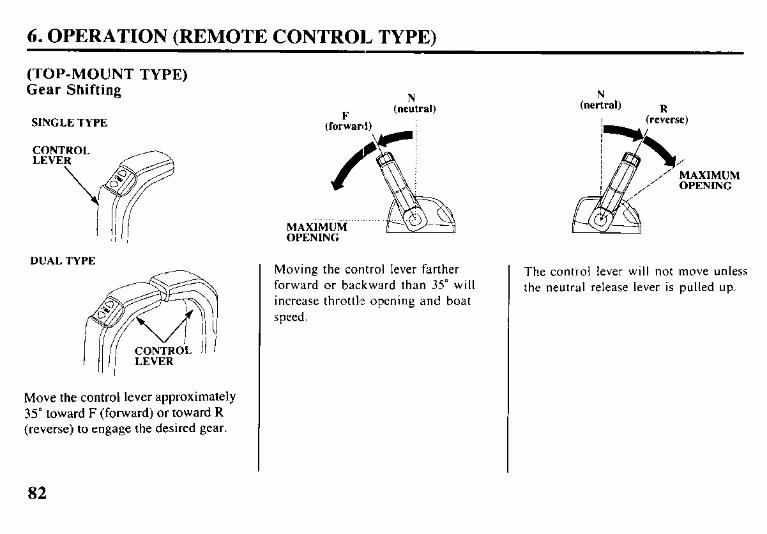
(TOP-MOUNT TYPE) Remote Control Lever
SINGLETYPE
DUALTYPE
” I CONTROL LEVERS
The remote contaol lever controls gear I selection and throttle opening posi-
tions.
THROTTI
REMOTECONTROLLEVER
F (forward): Moving the lever to the F position (approximately 35” from the N position) will engage the forward gear. Moving the lever farther into the F position will increase the throttle opening and the boat’s for- ward speed.
N (neutral): The engine idles and the nansmis- sion gears are disengaged.
OPENING
R (reverse): Moving the lever to the R position (approximately 35” from the N position) will engage the reverse gear. Moving the lever farther into the R position will increase the throttle opening and the boat’s reverse speed.
31
3. CONTROLS (REMOTE CONTROL TYPE)
Ignition Switch
SWITCH
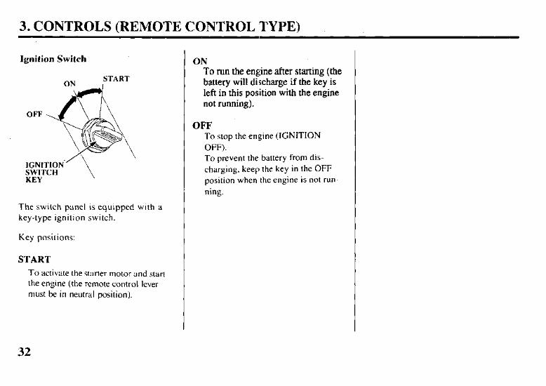
The switch panel is equipped with a key-type ignition switch.
Key positions:
START
To activate the starter motor and start the engine (the remote control lever must be in neutral position).
ON To run the engine after starting (the battery will discharge if the key is left in this position with the engine not running).
OFF To stop the engine (IGNITION OFF). To prevent the battery from dis- charging, keep the key in the OFF position when the engine is not run- ning.
32
3. CONTROLS (REMOTE CONTROL TYPE)
Emergency Stop Switch Lanyard
EMERGENCY
Y STOP SWITCH SWITCH CLIP LANYARD
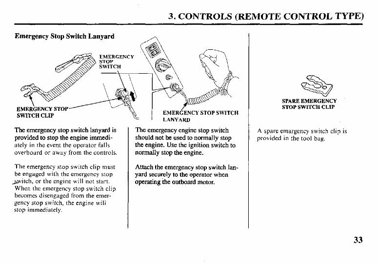
The emergency stop switch @yard is The emergency engine stop switch provided to stop the engine immedi- should not be used to normally stop ately in the event the operator falls the engine. Use the ignition switch to overboard or away from the controls. normally stop the engine.
The emergency stop switch clip must be engaged with the emergency stop
witch, or the engine will not start. When the emergency stop switch clip becomes disengaged from the emer- gency stop switch, the engine will stop immediately.
Attach the emergency stop switch lan- yard securely to the operator when operating the outboard motor.
SPARE EMERGENCY STOP SWITCH CLIP
A spare emargency switch clip is provided in the tool bag.
33
3. CONTROLS (REMOTE CONTROL TYPE)
Throttle Button
N (neutral)
BUTTON
Backward
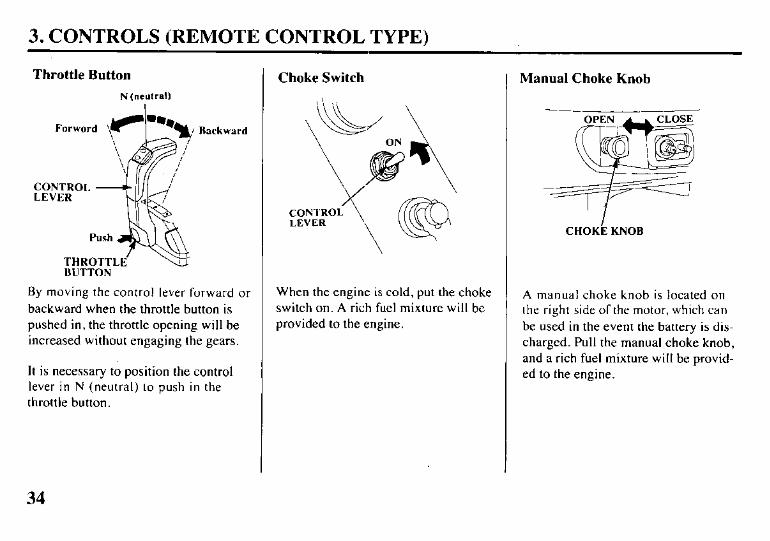
By moving the control lever forward or backward when the throttle button is pushed in, the throttle opening will be increased without engaging the gears.
It is necessary to position the control lever in N (neutral) to push in the throttle button.
Choke Switch
When the engine is cold, put the choke switch on. A rich fuel mixture will be provided to the engine.
Manual Choke Knob
CHOKL KNOB
A manual choke knob is located on the right side of the motor, which can be used in the event the battery is dis- charged. Pull the manual choke knob, and a rich fuel mixture will be provid- ed to the engine.
34
3. CONTROLS (REMOTE CONTROL TYPE)
Oil Pressure Indicator Light/Buzzer
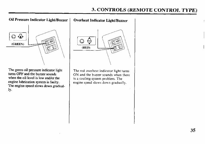
The green oil pressure indicator light turns OFF and the buzzer sounds when the oil level is low and/or the engine lubrication system is faulty. The engine speed slows down gradual- 1Y.
Overheat Indicator Light/Buzzer
The red overheat indicator light turns ON and the buzzer sounds when there is a cooling system problem. The engine speed slows down gradually.
35
3. CONTROLS (REMOTE CONTROL TYPE)
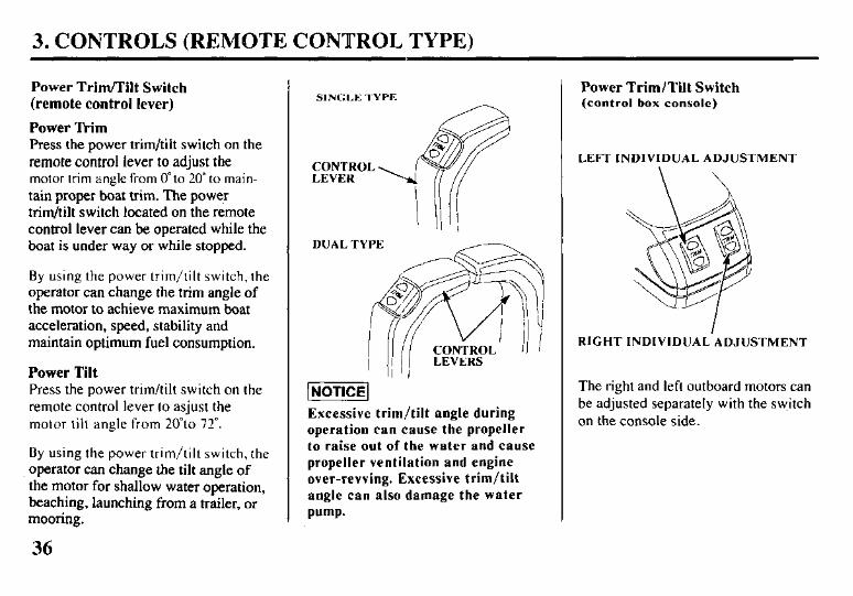
Power Trim/Tilt Switch
(remote control lever)
Power lkim
Press the power trim/tilt switch on the remote control lever to adjust the motor trim angle from 0” to 20” to main- tain proper boat trim. The power trim/tilt switch located on the remote control lever can be operated while the boat is under way or while stopped.
By using the power trim/tilt switch, the operator can change rhe trim angle of the motor to achieve maximum boat acceleration, speed, stability and maintain optimum fuel consumption.
Power Tilt
Press the power trim/tilt switch on the remote control lever to asjust the motor tilt angle from 20”to 72”.
By using the power trim/tilt switch, the operator can change the tilt angle of the motor for shallow water operation, beaching, launching from a trailer, or mooring.
36
SINGLE TYPE
CONTROL LEVER
DUAL TYYE
Excessive trim/tilt angle during
operation can cause the propeller
to raise out of the water and cause
propeller ventilation and engine
over-revving. Excessive trim/tilt
angle can also damage the water
pump.
Power Trim/Tilt Switch (control box console)
LEFT INDIVIDUAL ADJUSTMENT
RIGHT INDIVIDUAL’ADJUSTMENT
The right and left outboard motors can be adjusted separately with the switch on the console side.
3. CONTROLS (COMMON)
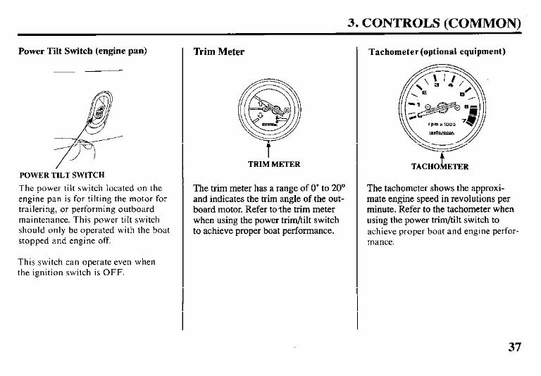
Power Tilt Switch (engine pan)
POWER TILT SWITCH
The power tilt switch located on the engine pan is for tilting the motor for trailering, or performing outboard maintenance. This power tilt switch should only be operated with the boat stopped and engine off.
This switch can operate even when the ignition switch is OFF.
Trim Meter
t TRIM METER
The trim meter has a range of 0” to 20” and indicates the trim angle of the out- board motor. Refer to,the trim meter when using the power trim/tilt switch to achieve proper boat performance.
Tachometer (optional equipment)
t TACHO ETER
The tachometer shows the approxi- mate engine speed in revolutions per minute. Refer to the tachometer when using the power trim/tilt switch to achieve proper boat and engine perfor- mance.
37
3. CONTROLS (COMMON)
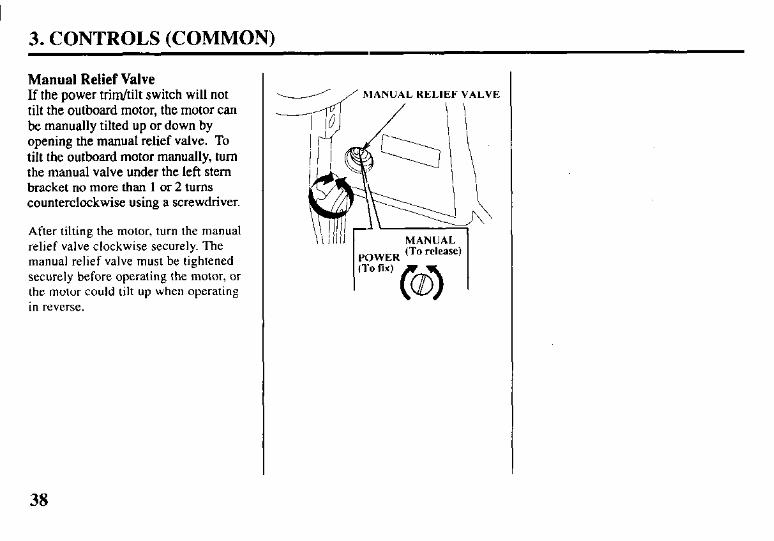
Manual Relief Valve If the power trim/tilt switch will not tilt the outboard motor, the motor can be manually tilted up or down by opening the manual relief valve. To tilt the outboard motor manually, turn the manual valve under the left stem bracket no more than 1 or 2 turns counterclockwise using a screwdriver.
After tilting the motor, turn the manual relief valve clockwise securely. The manual relief valve must be tightened securely before operating the motor, or the motor could tilt up when operating in reverse.
d / MANUAL RELIEF VALVE
POWER (To release) (To lix)
38
3. CONTROLS (COMMON)
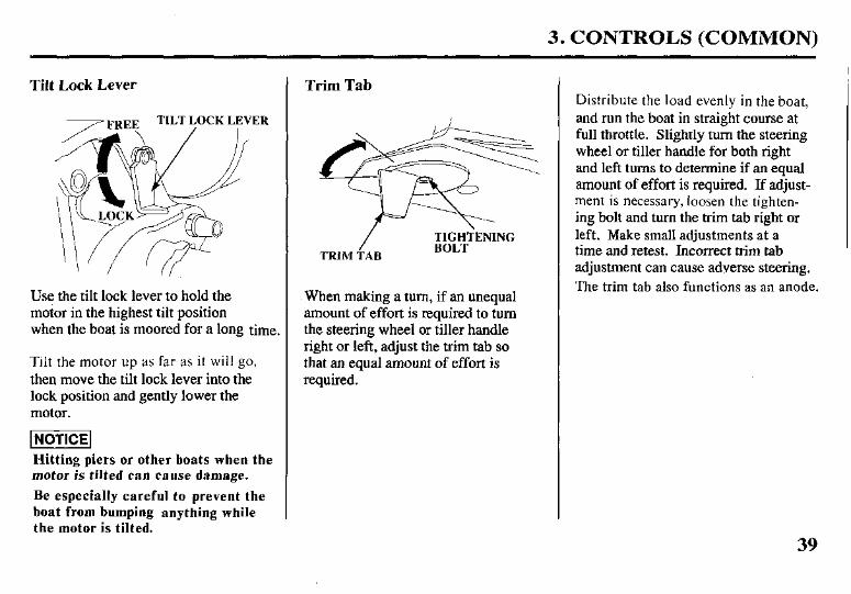
Tilt Lock Lever
‘ER
, /
Use the tilt lock lever to hold the motor in the highest tilt position when the boat is moored for a long time.
Tilt the motor up as far as it will go, then move the tilt lock lever into the lock position and gently lower the motor.
Hitting piers or other boats when the motor is tilted can cause damage.
Be especially careful to prevent the
boat from bumping anything while
the motor is tilted.
Trim Tab
/ TIGHT\ENING
TRIM TAB BOLT
When making a turn, if an unequal amount of effort is required to turn the steering wheel or tiller handle right or left, adjust the trim tab so that an equal amount of effort is required.
Distribute the load evenly in the boat, and run the boat in straight course at full throttle. Slightly turn the steering wheel or tiller handle for both right and left turns to determine if an equal amount of effort is required. If adjust- ment is necessary, loosen the tighten- ing bolt and turn the trim tab right or left. Make small adjustments at a time and retest. Incorrect trim tab adjustment can cause adverse steering. The trim tab also functions as an anode.
39
3. CONTROLS (COMMON)
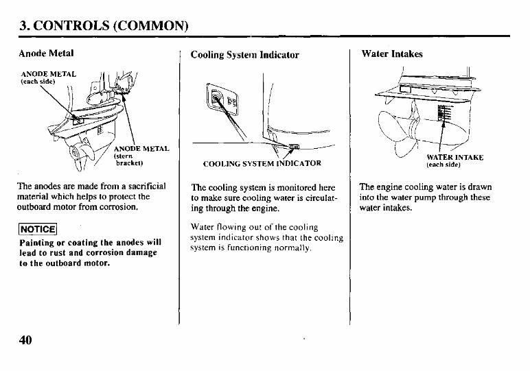
Anode Metal
AN0 (each
The anodes are made from a sacrificial material which helps to protect the outboard motor from corrosion.
1 NOTICE]
Painting or coating the anodes will
lead to rust and corrosion damage
to the outboard motor.
Cooling System Indicator
4 FL COOLING SYSTEM INDICATOR
The cooling system is monitored here to make sure cooling water is circulat- ing through the engine.
Water flowing out of the cooling system indicator shows that the cooling system is functioning normally.
Water Intakes
(each side)
The engine cooling water is drawn into the water pump through these water intakes.
40
3. CONTROLS (COMMON)
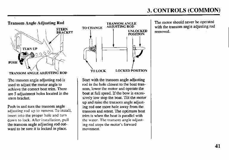
Transom Angle Adjusting Rod
ET
TRANSOM AiGLi ADJUSTING ROD
The transom angle adjusting rod is used to adjust the motor angle to achieve the correct boat trim. There are 5 adjustment holes located in the stem bracket.
Push,in and turn the transom angle adjusting rod up to remove. To install, insert into the proper hole and turn down to lock. After installation, pull the transom angle adjusting rod out- ward to be sure it is locked in place.
TRANSOM ANGLE TO CHANGE ADJUSTING ROD
UNLOCKED POSITION
TO LOCK LOCKED POSITION
Start with the transom angle adjusting rod in the hole closest to the boat tran- som, lower the motor and operate the boat at full speed. If the bow is exces- sively low stop the boat. Tilt the motor up and raise the transom angle adjust- ing rod one more hole away from the transom and retest. The optimum boat trim is when the boat is parallel with the water. The transom angle adjust- ing rod stops the motor’s forward movement.
The motor should never be operated with the transom angle adjusting rod removed.
41
3. CONTROLS (COMMON)
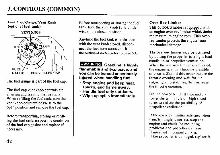
Fuel Cap/Gauge/Vent Knob
(optional fuel tank)
VENT KNOB
GAUGE FUEL FILLER CAP
The fuel gauge is part of the fuel cap.
The fuel cap vent knob controls air entering and leaving the fuel tank. When refilling the fuel tank, turn the vent knob counterclockwise to the open position and remove the fuel cap.
Before transporting, storing or refill- ing the fuel tank, inspect the condition of the fuel cap gasket and replace if necessary.
Before transporting or storing the fuel tank, turn the vent knob fully clock- wise to the closed position.
Anytime the fuel tank is in the boat with the vent knob closed, discon- nect the fuel hose connector from the outboard motor(refer to page 53).
flammable and explosive, and you can be burned or seriously injured when handling fuel. l Stop engine and keep heat,
sparks, and flame away. l Handle fuel only outdoors. l Wipe up spills immediately.
Over-Rev Limiter This outboard motor is equipped with
an engine over-rev limiter which limits the maximum engine rpm. This over- rev limiter protects the engine from mechanical damage.
The over-rev limiter may be activated by putting the propeller in a light load condition or propeller ventilation. When the over-rev limiter is activated, the engine rpm will become unstable or erratic. Should this occur, reduce the throttle opening and wait for the engine rpm to stabilize, then increase the throttle opening.
On the power trim/tilt type motors lower the trim angle on high speed turns to reduce the possibility of propeller ventilation.
If the over-rev limitter activates when trim/tilt angle is correct, stop the engine and check for mounting problems and propeller damage. If mounted improperly, fix it. If the propeller is damaged, replace it.
42
3. CONTROLS (COMMON)
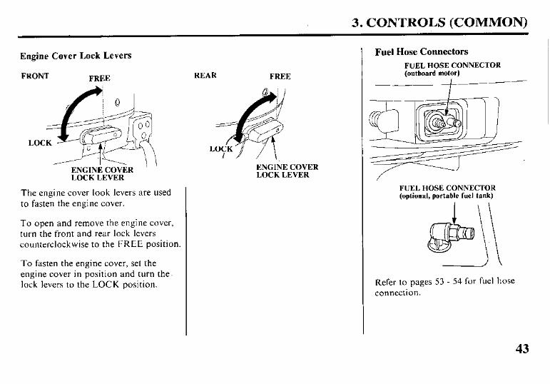
Engine Cover Lock Levers
FRONT FREE
ENGINE COVER ’ LOCK LEVER
The engine cover look levers are used to fasten the engine cover.
To open and remove the engine cover, turn the front and rear lock levers counterclockwise to the FREE position.
To fasten the engine cover, set the engine cover in position and turn the lock levers to the LOCK position.
REAR FREE
ENGINE COVER LOCK LEVER
Fuel Hose Connectors
FUEL HOSE CONNECTOR (outboard motor)
I
FUEL HOSE CONNECTOR (optional, portable fuel tank)
1’ Refer to pages 53 - 54 for fuel hose connection.
43
4. PRE-OPERATION CHECKS
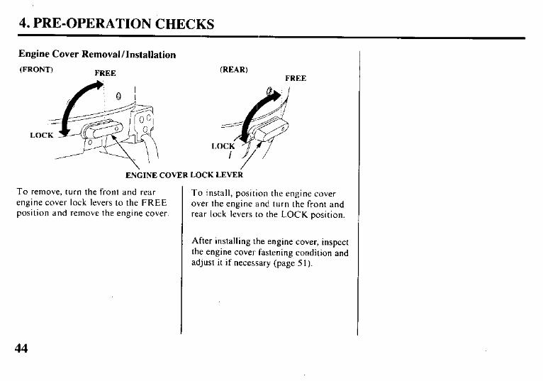
Engine Cover Removal/Installation
(FRONT) FREE (REAR)
ENGINE COVER LOCK LEVER
To remove, turn the front and rear engine cover lock levers to the FREE position and remove the engine cover.
To install, position the engine cover over the engine and turn the front and rear lock levers to the LOCK position.
After installing the engine cover, inspect the engine cover fastening condition and adjust it if necessary (page 5 1).
4. PRE-OPERATION CHECKS
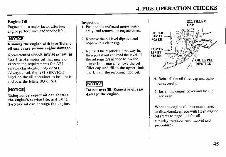
Engine Oil
Engine oil is a major factor affecting engine performance and service life.
Running the engine with insufficient
oil can cause serious engine damage.
Recommended oil:SAE low-30 or low-40
Use 4-stroke motor oil that meets or exceeds the requirements for API service classification SC or SH. Always check the API SERVICE label on the oil container to be sure it includes the letters SG or SH.
Using nondetergent oil can shorten
the engine’s service life, and using
2-stroke oil can damage the engine.
Inspection 1. Position the outboard motor verti-
cally, and remove the engine cover.
2. Remove the oil level dipstick and wipe with a clean rag.
3. Reinsert the dipstick all the way in, then pull it out and read the level. If the oil registers near or below the lower limit mark, remove the oil filler cap and fill to the upper limit mark with the recommended oil.
Do not overfill. Excessive oil can
damage the engine.
OIL FILLER CAP
UPPER LIMIT MARK
,OWER JMIT vIARK
4. Reinstall the oil filler cap and tight- en securely.
5. Install the engine cover and lock it securely.
When the engine oil is contaminated or discolored,replace with fresh engine oil (refer to page 111 for oil capacity, replacement interval and procedure).
45
4. PRE-OPERATION CHECKS
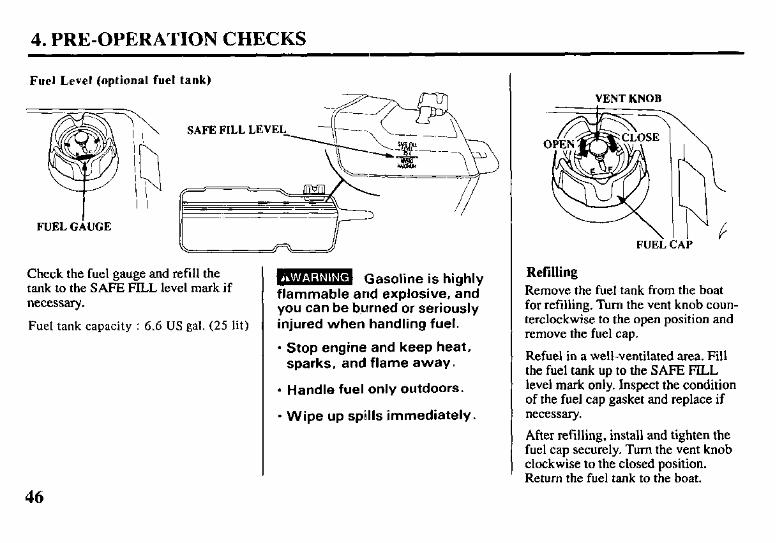
Fuel Level (optional fuel tank)
Check the fuel gauge and refill the tank to the SAFE FILL level mark if necessary.
Fuel tank capacity : 6.6 US gal. (25 lit)
B Gasoline is highly flammable and explosive, and you can be b.urned or seriously injured when handling fuel.
l Stop engine and keep heat, sparks, and flame away.
l Handle fuel only outdoors.
l Wipe up spills immediately.
VENT KNOB
FUEi
Refilling
\ 1 iC
b I k ‘AP
Remove the fuel tank from the boat for refilling. Turn the vent knob coun- terclockwise to the open position and remove the fuel cap.
Refuel in a well-ventilated area. Fill the fuel tank up to the SAFE FILL level mark only. Inspect the condition of the fuel cap gasket and replace if necessary.
After refilling, install and tighten the fuel cap securely. Turn the vent knob clockwise to the closed position. Return the fuel tank to the boat.
4. PRE-OPERATION CHECKS
Fuel Recommendations
Use unleaded gasoline with a pump octane rating of 86 or higher.
These outboard motors are certified to operate on unleaded gasoline. Unleaded gasoline produces fewer engine and spark plug deposits and extends exhaust system life.
Never use stale or contaminated gasoline or an oil/gaso- line mixture. Avoid getting dirt or water in the fuel tank.
Occasionally you may hear light “spark knock” or “ping- ing” (metallic rapping noise) while operating under heavy loads. This is no cause for concern.
If spark knock or pinging occurs at a steady engine speed, under normal load, change brands of gasoline. If spark knock or pinging persists, see an authorized Honda Ma- rine dealer.
Running the engine with persistent spark knock or pinging can cause engine damage.
Running the engine with persistent spark knock or ping- ing is misuse, and the Distributor’s Limited Warranty does not cover parts damaged by misuse.
47
4. PRE-OPERATION CHECK!3
Oxygenated Fuels
Some conventional gasolines are being blended with alco- hol or an ether compound. These gasolines are collec- tively referred to as oxygenated fuels. To meet clean air standards. some areas of the United States and Canada USC oxygenated fuels to help reduce emissions.
If you use an oxygenated fuel, be sure it is unleaded and meets the minimum octane rating rcquiremcnt.
Before using an oxygenated fuel, try to confirm the fuel’s contents. Some states/provinces require this information IO be posted on the pump.
The following are the EPA approved pcrcentagcs of oxy- genatcs:
ETHANOL - (ethyl or grain alcohol) IO% by volume You may use gasoline containing up to 10% ethanol by volume. Gasoline con- taining ethanol may be marketed under the name “Gasohol”.
MTBE - (Methyl Tertiary Butyl Ether) 15% by volume You may use gasoline containing up to 15% MTBE by volume.
METHANOL -(methyl or wood alcohol) 5% by volume You may use gasoline containing up to 5% methanol by volume, as long as it also contains cosolvents and corrosion inhibitors to protect the fuel system. Gasoline containing more than 5% methanol by volume may cause starting and/or performance problems. It may also damage metal, rubber. and plastic parts of your fuel system.
If you notice any undesirable operating symptoms, try an- other service station, or switch to another brand of gaso- line.
Fuel system damage or performance problems resulting from the use of an oxygenated fuel containing more than the percentages of oxygenates mentioned above are not covered under warranty.
48
4. PRE-OPERATION CHECKS
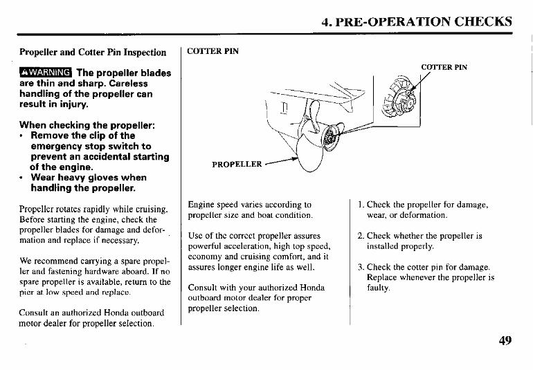
Propeller and Cotter Pin Inspection
m The propeller blades are thin and sharp. Careless handling of the propeller can result in injury.
When checking the propeller: l Remove the clip of the
emergency stop switch to prevent an accidental starting of the engine.
l Wear heavy gloves when handling the propeller.
Propeller rotates rapidly while cruising. Before starting the engine, check the propeller blades for damage and defor- mation and replace if necessary.
We recommend carrying a spare propel- ler and fastening hardware aboard. If no spare propeller is available, return to the pier at low speed and replace.
Consult an authorized Honda outboard motor dealer for propeller selection.
COTTER PIN
COTTER PIN
PROPELLER Ao
Engine speed varies according to propeller size and boat condition.
Use of the correct propeller assures powerful acceleration, high top speed, economy and cruising comfort, and it assures longer engine life as well.
Consult with your authorized Honda outboard motor dealer for proper propeller selection.
1. Check the propeller for damage, wear, or deformation.
2. Check whether the propeller is installed properly.
3. Check the cotter pin for damage. Replace whenever the propeller is faulty.
49
4. PRE-OPERATION CHECKS
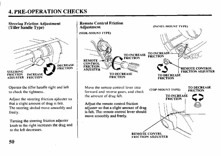
Steering Friction Adjustment (Tiller handle Type)
ST FR ADJUSTER FRICTION
Remote Control Friction Adjustment
(SIDE-MOUNT TYPE)
(PANEI.-MOUNT TYPE)
REMOTE CONTROL FRICTION ADJUSTER
TO DECREASE FRICTION TO DECREASE
FRICTION
Operate the tiller handle right and left to check the tightness.
Adjust the steering friction ajduster so that a slight amount of drag is felt. The steering sholud move smoothly and freely.
Turning the steering friction adjuster knob to the right increases the drag and to the left decreases.
50
Move the remote control lever into (TOP-MOUNT TYPE)
TO DECREASE forward and reverse gears, and check FRICTION
the amount of drag felt.
Adjust the remote control friction adjuster so that a slight amount of drag is felt. The remote control lever should move smoothly and freely.
REMOTE CONTRL FRICTION ADJUSTER
4. PRE-OPERATION CHECKS
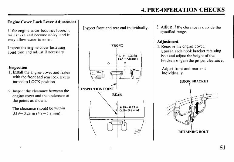
Engine Cover Lock Lever Adjustment
If the engine cover becomes loose, it will shake and become noisy, and it may allow water to enter.
Inspect the engine cover fastenipg condition and adjust if necessary.
Inspection 1. Install the engine cover and fasten
with the front and rear lock levers turned to LOCK position.
2. Inspect the clearance between the engine cover and the undercase at the points as shown.
The clearance should be within 0.19-0.23 in (4.8-5.8 mm).
Inspect front and rear end individually.
FRONT
INSPECTION POINT
\ REAR
0 ’ \!1 1 0.19-0.23 in
(7 (4-8 - 5.8 mm)
3. Adjust if the clerance is outside the specified range.
Adjustment 1. Remove the engine cover.
Loosen each hook bracket retaining bolt and adjust the height of the brackets to gain the proper clearance.
Adjust front and rear end individually.
HOOK BRACKET
I
RETAINING BOLT
51
4. PRE-OPERATION CHECKS
2. After the adjustment, tighten the bolts securely and install the engine cover.
Reinspect the clearance and readjust if necessary.
Other Checks
Check the following items:
I. The fuel hose for kinking, collapsing or loose connections.
2. The stern bracket for damage and mounting bolts for proper torque.
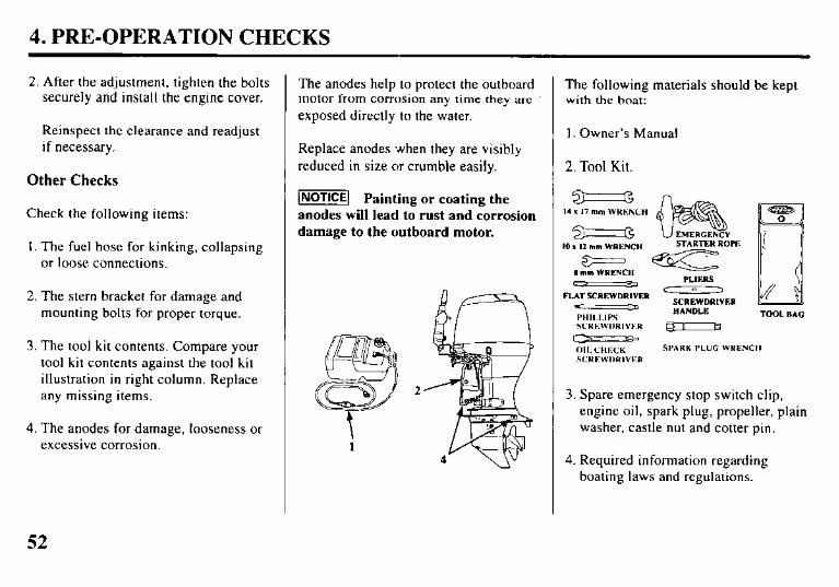
3. The tool kit contents. Compare your tool kit contents against the tool kit illustration in right column. Replace any missing items.
4. The anodes for damage, looseness or excessive corrosion.
The anodes help to protect the outboard motor from corrosion any time they are
exposed directly to the water.
Replace anodes when they are visibly reduced in size or crumble easily.
-1 Painting or coating the anodes will lead to rust and corrosion damage to the outboard motor.
i
The following materials should be kept with the boat:
1. Owner’s Manual
2. Tool Kit.
3 14 x 17 mm WRKNCH
10 I I2 mm WRENCH
0 mm WRENCH
FLAT SCREWDRIVER 3
I’HII.I.IPs SCREWDRIVKR -
STARTER ROPE
=c PLIFS
D ,
SCREWDRIVER HANDLE TOOL RAG
c-=- - (HI. CHECK SPARK PLUG WRENCH
SCREWDRIVER
3. Spare emergency stop switch clip, engine oil, spark plug, propeller, plain washer, castle nut and cotter pin.
4. Required information regarding boating laws and regulations.
52
5. STARTING THE ENGINE
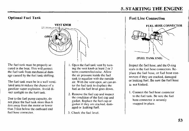
Optional Fuel Tank
VENT KNOB
The fuel tank must be properly se- cured in the boat. This will protect the fuel tank from mechanical dam- age caused by the fuel tank shifting.
The fuel tank must be in a well venti- lated area to reduce the chance of a gasoline vapor explosion. Avoid di- rect sunlight on the fuel tank.
Due to the fuel pump capacity, do not place the fuel tank more than 6 feet away from the motor or lower than 3 feet below the outboard end fuel hose connector.
I. Open the fuel tank vent by turn- ing the vent knob at least 2 or 3 turns counterclockwise. Allow the air pressure inside the fuel tank to equalize with the outside air. With the vent open, air can en- ter the fuel tank to displace the fuel as the fuel level goes down.
2. Remove the fuel cap and inspect the condition of the fuel cap and gasket. Replace the fuel cap or gasket if they are cracked, dam- aged or leaking fuel.
3. Check the fuel level.
Fuel Line Connection
FUEL HOSE CONNECTOR
(FUEL TANK END)\
Inspect the fuel hose, and the O-ring seals in the fuel hose connectors. Re- place the fuel hose, or fuel hose con- nectors if they are cracked, damaged or leaking fuel. Be sure the fuel hose is not kinked.
I. Connect the fuel hose connector to the fuel tank. Be sure the fuel hose connector is securely snapped in place.
53
5. STARTING THE ENGINE
FUEL HOSE CONNkXTOH
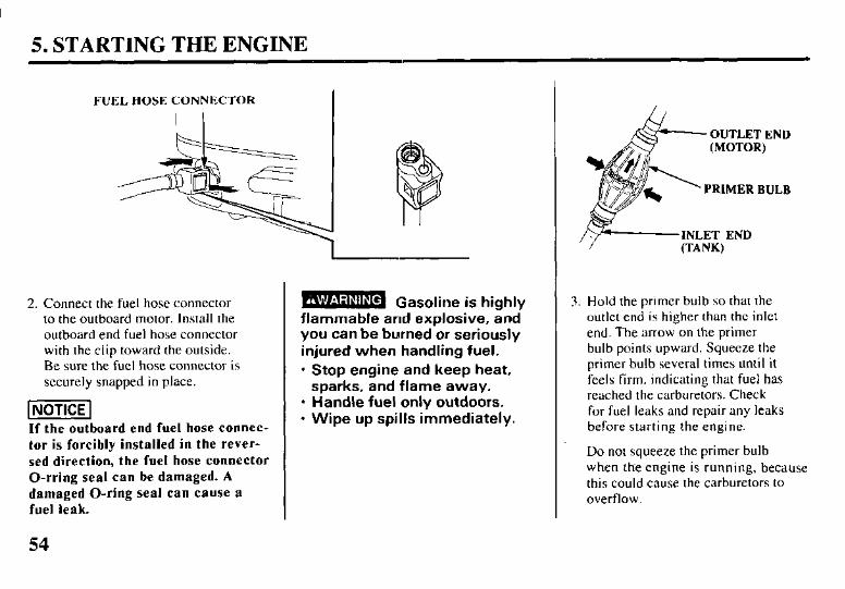
2. Connect the fuel hose connector to the outboard motor. Install the outboard end fuel hose connector with the clip toward the outside. Be sure the fuel hose connector is securely snapped in place.
(NoTICE If the outboard end fuel hose connec-
tor is forcibly installed in the rever-
sed direction, the fuel hose connector 0-rring seal can be damaged. A
damaged O-ring seal can cause a
fuel leak.
54
m Gasoline is hinhlv flammable and explosive, and you can be burned or seriously injured when handling fuel. l Stop engine and keep heat,
sparks, and flame away. l Handle fuel only outdoors. l Wipe up spills immediately.
OUTLET END OUTLET END
PRIMER BULB PRIMER BULB
3. Hold the primer bulb so that the outlet end is higher than the inlet end. The arrow on the primer bulb points upward. Squeeze the primer bulb several times until it feels firm, indicating that fuel has reached the carburetors. Check for fuel leaks and repair any leaks before starting the engine.
Do not squeeze the primer bulb when the engine is running, because this could cause the carburetors to overflow.
5. STARTING THE ENGINE (TILLER HANDLE TYPE)
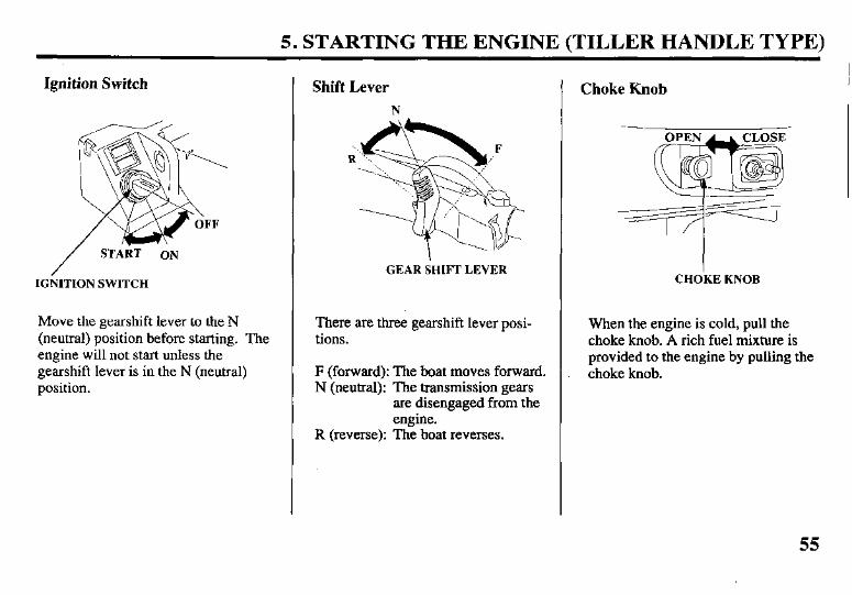
Ignition Switch
IGkITION SWITCH
Move the gearshift lever to the N (neutral) position before starting. The engine will not start unless the gearshift lever is in the N (neutral) position.
Shift Lever
N
GEAR SHIFT LEVER
There are three gearshift lever posi- tions.
F (forward): The boat moves forward. N (neutral): The transmission gears
are disengaged from the engine.
R (reverse): The boat reverses.
Choke Knob
CHO’KE KNOB
When the engine is cold, pull the choke knob. A rich fuel mixture is provided to the engine by pulling the choke knob.
55
5. STARTING THE ENGINE (TILLER HANDLE TYPE)
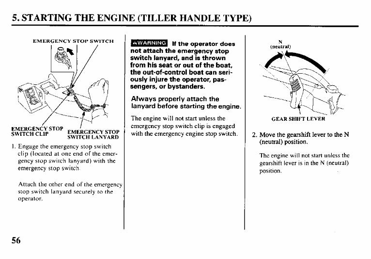
EMERGENCY STOP SWITCH
&l;;~f~;;STOP EMEkCENCY STOP SWITCH LANYARD
I. Engage the emergency stop switch clip (located at one end of the emer- gency stop switch lanyard) with the emergency stop switch.
Attach the other end of the emergency stop switch lanyard securely to the operator.
m If the operator does not attach the emergency stop switch lanyard, and is thrown from his seat or out of the boat, the out-of-control boat can seri- ously injure ttne operator, pas- sengers, or bystanders.
Always properly attach the lanyard before starting the engine.
The engine will not start unless the emergency stop switch clip is engaged with the emergency engine stop switch.
GEAR SHIFT LEVER-
2. Move the gearshift lever to the N (neutral) position.
The engine will not start unless the gearshift lever is in the N (neutral) position.
56
5. STARTING THE ENGINE (TILLER HANDLE TYPE)
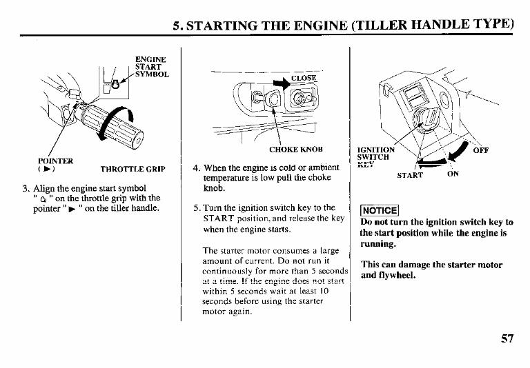
POINTER (b) THROTTLE GRIP
3. Align the engine start symbol ” QI ” on the throttle grip with the pointer ” ) ” on the tiller handle.
CH‘OKE KNOB
4. When the engine is cold or ambient temperature is low pull the choke knob.
5. Turn the ignition switch key to the START position, and release the key when the engine starts.
The starter motor consumes a large amount of current. Do not run it continuously for more than 5 seconds at a time. If the engine does not start within 5 seconds wait at least IO seconds before using the starter motor again.
STAii ON
Do not turn the ignition switch key to the start position while the engine is running.
This can damage the starter motor and flywheel.
57

5. STARTING THE ENGINE (TILLER HANDLE TYPE)
CHOKi KNOB THROTTLE GRIP
6. If it was necessary to use the choke knob to start the engine, slowly return it to its initial position. Turn the throttle grip in the SLOW direction to a position where the engine does not stall.
7. After the engine starts, verify that water is flowing through the cooling system by monitoring the cooling system indicator. The amount of water coming out of the cooling system indicator will vary due to thermostat operation. Stop the engine if water does not come out of the cooling system indicator or if you see steam.
WATER 1NTAKE
Check the water intake sereens and the cooling system indicator discharge port, and if necessary remove any obstructions. If the problem continues, contact your closest authorized Honda Marine dealer.
l Running the outboard motor with an obstruction in the
cooling system can damage the water pump and
overheat the engine.
l The propeller must remain underwater. Running the
out board motor out of water will damage the water
pump and overheat the engine.
58
5. STARTING THE ENGINE (TILLER HANDLE TYPE)
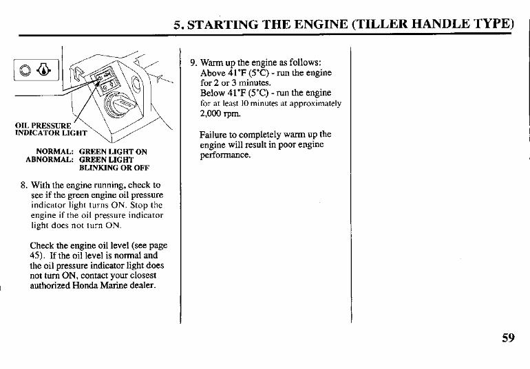
NORMAL: GREEN LIGHT ON ABNORMAL: GREEN LIGHT
BLINKING OR OFF
8. With the engine running, check to see if the green engine oil pressure indicator light turns ON. Stop the engine if the oil pressure indicator light does not turn ON.
Check the engine oil level (see page 45). If the oil level is normal and the oil pressure indicator light does not turn ON, contact your closest authorized Honda Marine dealer.
9. Warm up the engine as follows: Above 41°F (5’C) - run the engine for 2 or 3 minutes. Below 41°F (5°C) - run the engine for at least IO minutes at approximately 2,000 rpm.
Failure to completely warm up the engine will result in poor engine performance.
5. STARTING THE ENGINE (REMOTE CONTROL TYPE)
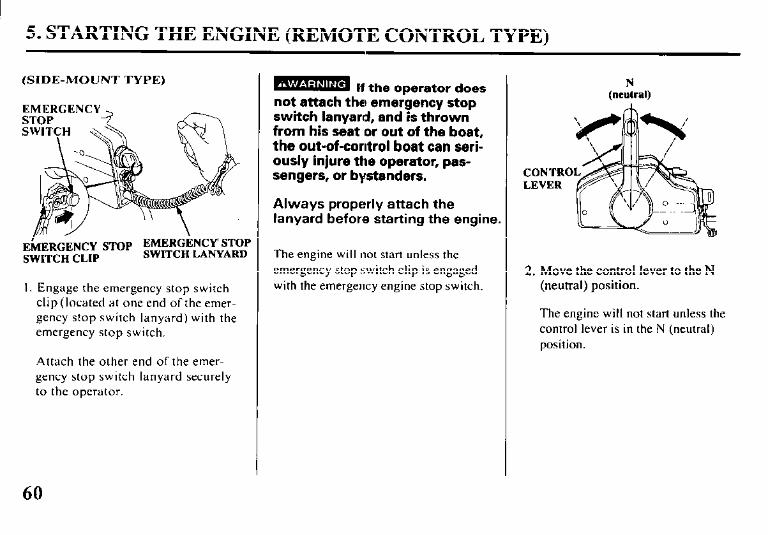
(SIDE-MOUNT TYPE)
I. Engage the emergency stop switch clip (located at one end of the emer- gency stop switch lanyard) with the emergency stop switch.
Attach the other end of the emer- gency stop switch lanyard securely to the operator.
- If the orxwator does not attach the emeigency stop switch lanyard, and is thrown from his seat or out of the boat, the out-of-control boat can seri- ously injure the operator, pas- sengers, or bystanders.
Always properly attach the lanyard before starting the engine.
The engine will not start unless the emergency stop switch clip is engaged with the emergency engine stop switch.
CONTRO LEVER
2. Move the control lever to the N (neutral) position.
The engine will not start unless the control lever is in the N (neutral) position.
60
5. STARTING THE ENGINE (REMOTE CONTROL TYPE)
FAST
CHOKEiFAST IDLE LEVER vu
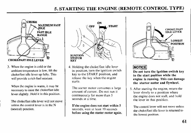
3. When the engine is cold or the ambient temperature is low, lift the choke/fast idle lever up fully. This will provide a rich fuel mixture.
When the engine is warm, it may be necessary to raise the choke/fast idle lever slightly. Hold it in this position.
The choke/fast idle lever will not move unless the control lever is in the N (neutral) position.
4. Holding the choke/fast idle lever in position, turn the ignition switch key to the START position, and release the key when the engine starts.
The starter motor consumes a large amount of current. Do not run it continuously for more than 5 seconds at a time.
If the engine does not start within 5 seconds, wait at least IO seconds before using the starter motor again.
n
CHOKE/FAST IDLE LEVER
Do not turn the ignition switch key
to the start position while the
engine is running. This can damage
the starter motor and flywheel.
5. After starting the engine, return the lever slowly to a position where the engine does not stall, and hold the lever in that position.
The control lever will not move unless the choke/fast idle lever is returned to the lowest position.
61

5. STARTING THE ENGINE (REMOTE CONTROL TYPE)
WATER INTAKE (each side)
6. After the engine starts, verify water is flowing through the cooling system by monitoring the cooling system indica- tor. The amount of water coming out of the cooling sys- tem indicator will vary due to thermostat operation. Stop the engine if water does not come out of the cooling sys- tem indicator or if you see steam. Check the water intake screens and the cooling system indicator discharge port, and if necessary remove any obstructions. If the problem continues, contact your closest authorized Honda Marine dealer.
l Running the outboard motor with an obstruction in the
cooling system can damage the water pump and
overheat the engine. l The propeller must remain underwater. Running the
outboard motor out of the water will damage the water
pump and overheat the engine.
OIL PRESSURE INDICATOR LIGHT
NORMALGREEN LIGHT ON ABNORMAL:GREEN LIGHT BLINKING
OR OFF
7. With the engine running, check to see if the green engine oil pressure indicator light turns ON. Stop the engine if the oil pressure indicator light does not turn ON. Check the engine oil level (see page 45). If the oil level is normal and the oil pressure indicator light does not turn ON, contact your closest authorized Honda Marine dealer.
8. Warm up the engine as follows: Above 41’F (5’C) - run the engine for 2 or 3 minutes. Below 41°F (5’C) -run the engine for at least IO minutes at approximately 2,000 rpm.
Failure to completely warm up the engine will result in poor engine performance.
5. STARTING THE ENGINE (REMOTE CONTROL TYPE)
(PANEL-MOUNT TYPE)
I EMEIiGIiNCY STOP
;;~$-jj;;~&SToP SWITCH LANYARD
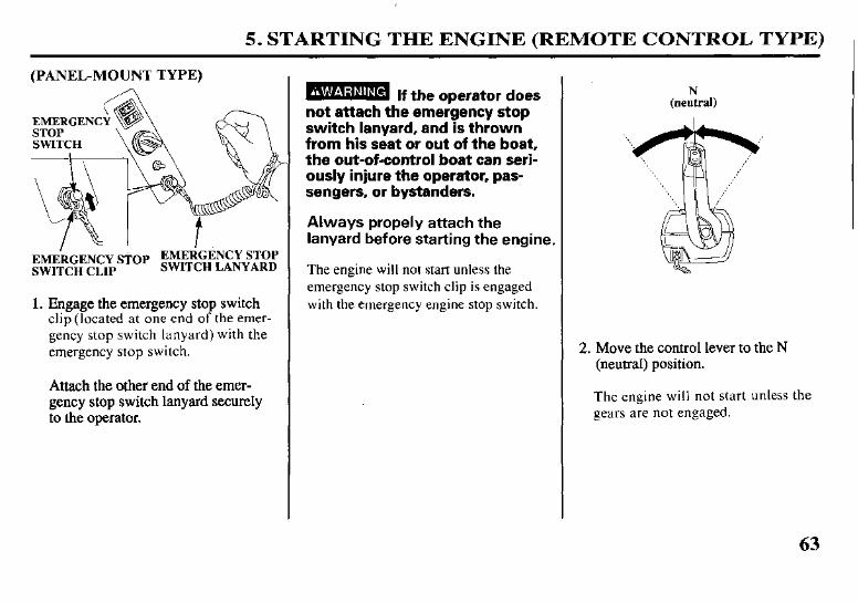
1. Engage the emergency stop switch clip (located at one end of the emer- gency stop switch lanyard) with the emergency stop switch.
Attach the other end of the emer- gency stop switch lanyard securely to the operator.
- If the ooerator does not attach the emeigency stop switch lanyard, and is thrown from his seat or out of the boat, the out-of-control boat can seri- ously injure the operator, pas- sengers, or bystanders.
Always propely attach the lanyard before starting the engine.
The engine will not start unless the emergency stop switch clip is engaged with the emergency engine stop switch.
N (neutral)
2. Move the control lever to the N (neutral) position.
The engine will not start unless the gears are not engaged.
63
5. STARTING THE ENGINE (REMOTE CONTROL TYPE)
N (neutral)
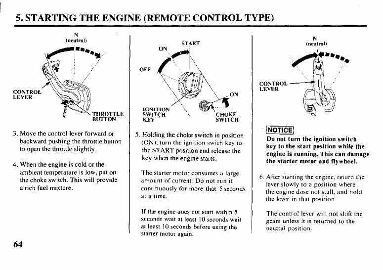
3. Move the control lever forward or backward pushing the throttle button to open the throttle slightly.
4. When the engine is cold or the ambient temperature is low, put on the choke switch. This will provide a rich fuel mixture.
START
KEY SWITCH
5. Holding the choke switch in position (ON), turn the ignition swich key to the START position and release the key when the engine starts.
The starter motor consumes a large amount ofcurrent. Do not run it continuously for more that 5 seconds at a time.
If the engine does not start within 5 seconds wait at least 10 seconds wait at least 10 seconds before using the starter motor again.
[NOTICE] Do not turn the ignition switch
kev to the start position while the
I ” engine is running. This can damage
the starter motor and flywheel.
6. After starting the engine, return the lever slowly to a position where the engine dose not stall, and hold the lever in that position.
The control lever will not shift the gears unless it is returned to the neutral position.
5. STARTING THE ENGINE (REMOTE CONTROL TYPE)
COOLING SYSTEM INDICATOR
WATER INTAKE (each side)
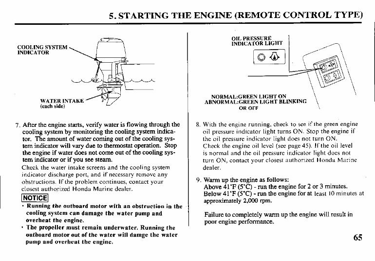
7. After the engine starts, verify water is flowing through the cooling system by monitoring the cooling system indica- tor. The amount of water coming out of the cooling sys- tem indicator will vary due to thermostat operation. Stop the engine if water does not come out of the cooling sys- tern indicator or if you see steam. Check the water intake screens and the cooling system indicator discharge port, and if necessary remove any obstructions. If the problem continues, contact your closest authorized Honda Marine dealer.
piEEiq - Running the outboard motor with an obstruction in the
cooling system can damage the water pump and
overheat the engine.
- The propeller must remain underwater. Running the
outboard motor out of the water will damge the water pump and overheat the engine.
OIL PRESSURE INDICATOR LIGHT
NORMAL:GREEN LIGHT ON \
ABNORMAL:GREEN LIGHT BLINKING OR OFF \
8. With the engine running, check to see if the green engine oil pressure indicator light turns ON. Stop the engine if the oil pressure indicator light does not turn ON. Check the engine oil level (see page 45). If the oil level is normal and the oil pressure indicator light does not turn ON, contact your closest authorized Honda Marine dealer.
9. Warm up the engine as follows: Above 41’F (5°C) - run the engine for 2 or 3 minutes. Below 41°F (YC) - run the engine for at least IO minutes at approximately 2,000 rpm.
Failure to completely warm up the engine will result in poor engine performance.
65
5. STARTING THE ENGINE (REMOTE CONTROL TYPE)
(TOP-MOUNT TYPE)
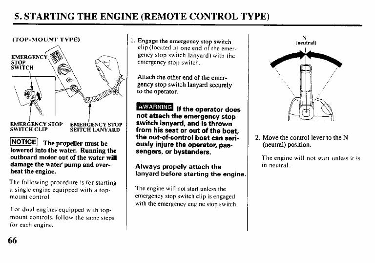
EMERGENCY STOP EMERbENCY STOP SWITCH CLIP SEITCH LANYARD
-1 Th e propeller must be lowered into the water. Running the outboard motor out of the water will damage the water’pump and over- heat the engine.
The following procedure is for starting a single engine quipped with a top- mount control.
For dual engines equipped with top- mount controls. follow the same steps for each engine.
1. Engage the emergency stop switch clip (located 81 one end of the emer- gency stop switch lanyard) with the emergency stop switch.
Attach the other end of the emer- gency stop switch lanyard securely to the operator.
miEmm If the oDerator does not attach the emeigency stop switch lanyard, and is thrown from his seat or out of the boat, the out-of-control boat can seri- ously injure the operator, pas- sengers, or bystanders.
Always propely attach the lanyard before starting the engine.
The engine will not start unless the emergency stop switch clip is engaged with the emergency engine stop switch.
N (neutral)
2. Move the control lever to the N (neutral) position.
The engine will not start unless it is in neutral.
: 5. STARTING THE ENGINE (REMOTE CONTROL TYPE)
N (neutral)
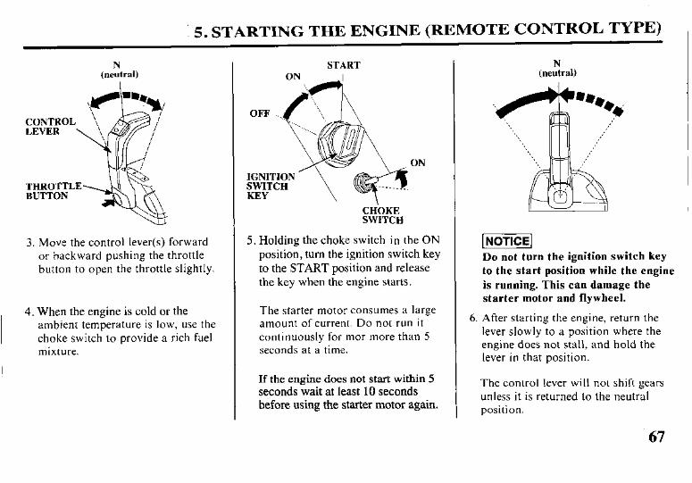
3. Move the control lever(s) forward or backward pushing the throttle button to open the throttle slightly.
4. When the engine is cold or the ambient temperature is low, use the choke switch to provide a rich fuel mixture.
START ON I
ON
CHbKE SWITCH
5. Holding the choke switch in the ON position, turn the ignition switch key to the START position and release the key when the engine starts.
The starter motor consumes a large amount of current. Do not run it continuously for mor more than 5 seconds at a time.
If the engine does not start within 5 seconds wait at least 10 seconds before using the starter motor again.
N (neutral)
[NOTICE/
Do not turn the ignition switch key
to the start position while the engine
is running. This can damage the
starter motor and flywheel.
6. After starting the engine, return the lever slowly to a position where the engine does not stall, and hold the lever in that position.
The control lever will not shift gears unless it is returned to the neutral position.
67

5. STARTING THE ENGINE (REMOTE CONTROL TYPE)
INDICATOR
WATER INTAKE (each side)
7. After the engine starts, verify water is flowing through the cooling system by monitoring the cooling system indica- tor. The amount of water coming out of the cooling sys- tem indicator will vary due to thermostat operation. Stop the engine if water does not come out of the cooling sys- tem indicator or if you see steam. Check the water intake screens and the cooling system indicator discharge port, and if necessary remove any obstructions. If the problem continues, contact your closest authorized Honda Marine dealer.
pi?ziEq l Running the outboard motor with an obstruction in the
cooliog system can damage the water pump and over- heat the engine.
l The propeller must remain underwater. Running the
outboard motor out of the water will damage the water pump and over the engine.
68
OIL PRESSURE INDICATOR LIGHT
\ NORMAL: GREEN LIGHT ON
ABNORMAL: GREEN LIGHT BLINKING OR OFF
8. With the engine running, check to see if the green engine oil pressure indicator light turns ON. Stop the engine if the oil pressure indicator light does not turn ON. Check the engine oil level (see page 45). If the oil level is normal and the oil pressure indicator light does not turn ON, contact your closest authorized Honda Marine dealer.
9. Warm up the engine as follows: Above 41’F (5°C) - run the engine for 2 or 3 minutes. Below 41’F (5’C) - run the engine for at least IO minutes at approximately 2,000 rpm.
Failure to completely warm up the engine will result in poor engine performance.
5. STARTING THE ENGINE (EMERGENCY STARTING)
Emergency Starting
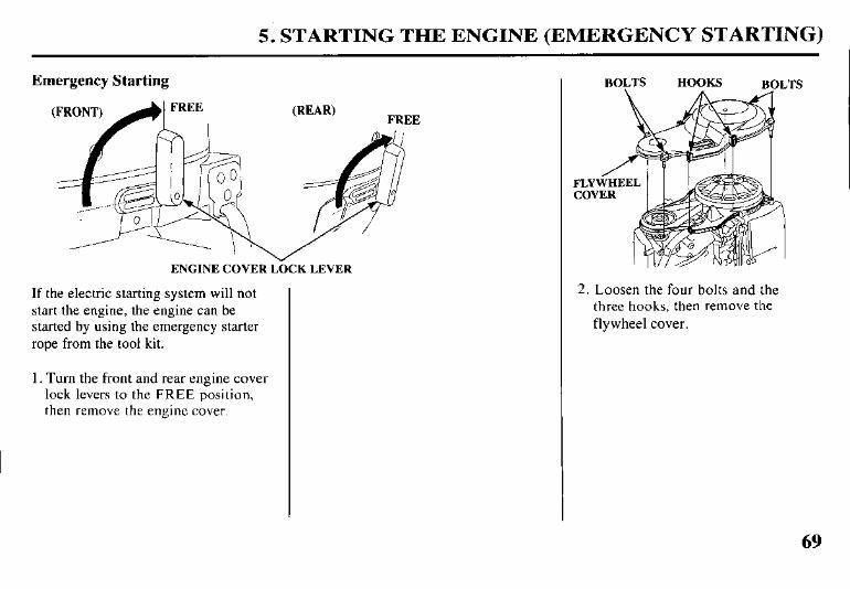
ENGINE COVER L&K LEVER
If the electric starting system will not start the engine, the engine can be started by using the emergency starter rope from the tool kit.
1. Turn the front and rear engine cover lock levers to the FREE position, then remove the engine cover.
BOLTS HOOKS BOLTS
2. Loosen the four bolts and the three hooks, then remove the flywheel cover.
69
5. STARTING THE ENGINE (EMERG:ENCY STARTING)
TILLER HADLE TYPE (TILLER HANDLE TYPE)
N (neutral)
(REMOTE CONTROL TYPE) SIDE-MOUNT
(neufral)
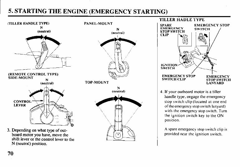
3. Depending on what type of out- board motor you have, move the shift lever or the control lever to the N (neutral) position.
70
PANEL-IMOUNT
N (neutral)
TOP-MOUNT
SPARE MERGENCY
:TOP SW1 CLIP
EMERGENCY STOP SW ITCH /
IGNITION SWITCH
EMERGENCY STOP SWITCH CLIP
EMERGENCY STOP SWITCH LANYARD
N (neutral) 4. If your outboard motor is a tiller
handle type, engage the emergency stop switch clip (located at one end of the emergency stop switch lanyard) with the emergency stop switch. Turn
,,,,’ the ignition switch key to the ON position.
A spare emergency stop switch clip is provided near the ignition switch.

5. STARTING THE ENGINE (EMERGENCY STARTING)
SIDE-MOUNT TYPE PANEL-MOUNT TYPE, TOP MOUNT TYPE
IGNITION KEY
NCY ITCH
EMEkGENCY STOP SWITCH LANYARD
5. If your outboard motor is a remote control type, engage the emergency stop switch clip (located at one end of the emergency stop switch lanyard) with the emergency stop switch.
Turn the ignition switch key to the ON position.
A spare emergency stop switch clip is provided on remote control box (side- mount type) or in the tool bag (panel- mount and top mount type).
CHbKE KNOB
6. If the engine is cold or the ambient temperature is low, pull the manual choke knob located on the front of the outboard motor.
71
5. STARTING THE ENGINE (EMERGENCY STARTING)
(TILLER HANDLE TYPE)
ENGINE START SYMBOL
POIN/TER I THROTTLE GRIP
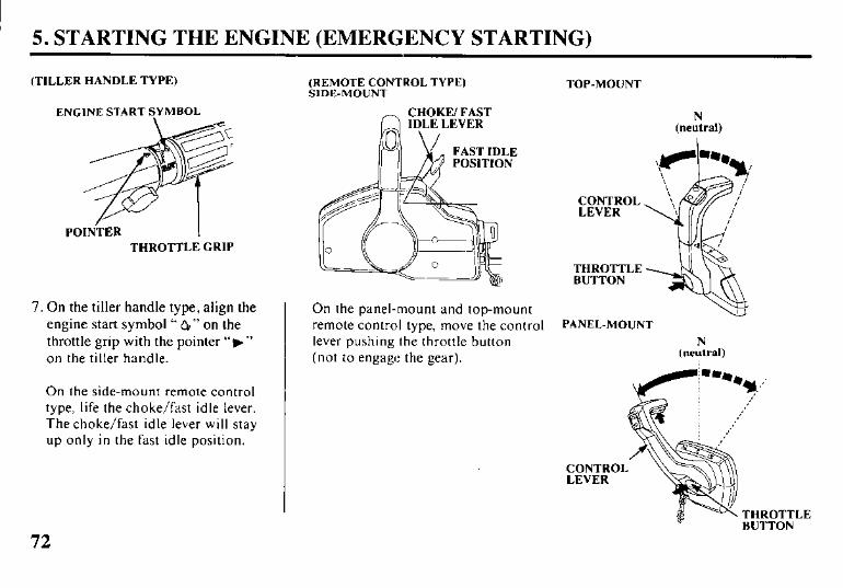
7. On the tiller handle type, align the On the panel-mount and top-mount engine start symbol “ QI” on the remote control type, move the control throttle grip with the pointer “b” lever pushing the throttle button on the tiller handle. (not to engage the gear).
On the side-mount remote control type, life the choke/fast idle lever. The choke/fast idle lever will stay up only in the fast idle position.
(REMOTE CONTROL TYPE) SIDE-MOUNT
TOP-MOUNI
CHOKE/ FAST
CONTROL LEVER
THROTTLE BUTTON
PANEL-MOUNT
N (neutral)
THROTTLE
72
5. STARTING THE ENGINE (EMERGENCY STARTING)
FLYWHEEL
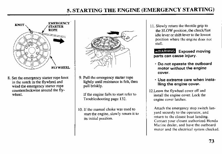
8. Set the emergency starter rope knot in the notch in the flywheel and wind the emergency starter rope counterclockwise around the fly- wheel.
9. Pull the emergency starter rope lightly until resistance is felt, then pull briskly.
If the engine fails to start refer to Troubleshooting page 132.
10. If the manual choke was used to start the engine, slowly return it to its initial position.
11. Slowly return the throttle grip to the SLOW position, the chock/fast idle lever or shift lever to the lowest position where the engine does not stall.
B Exposed moving parts can cause injury.
l Do not operate the outboard motor without the engine cover.
l Use extreme care when insta- lling the engine cover.
12.Leave the flywheel cover off and install the engine cover. Lock the engine cover latches.
Attach the emergency stop switch lan- yard securely to the operator, and return to the closest boat landing. Contact your closest authorized Honda Marine dealer, and have the outboard motor and the electrical system checked.
5. STARTING THE ENGINE (TROUEiLESHOOTING)
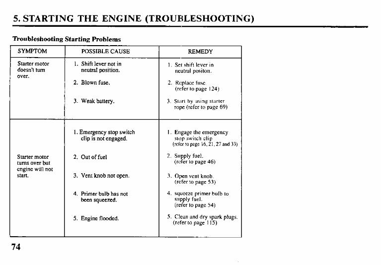
Troubleshooting Starting Problems
SYMPTOM
Starter motor doesn’t turn over.
Starter motor turns over but engine will not start.
POSSIBLE CAUSE
1. Shift lever not in neutral position.
2. Blown fuse.
3. Weak battery.
1. Emergency stop switch clip is not engaged.
2. Out of fuel
3. Vent knob not open.
4. Primer bulb has not been squeezed.
5. Engine flooded.
REMEDY
I. Set shift lever in neutral positon.
2. Replace fuse. (refer to page 124)
3. St;irt by using starter rope (refer to page 69)
1. Engage the emergency stop switch clip
(refer to page 16,2 I, 27 and 33)
2. Supply fuel. (refer to page 46)
3. Open vent knob. (refer to page 53)
4. squeeze primer bulb to supply fuel. (refer to page 54)
5. Clean and dry spark plugs. (refer to page I 15)
74
6. OPERATION
Break-in Procedure Break-in period 10 hours
Break-in operation allows the moving parts to wear-in evenly and thus ensures proper performance and longer outboard motor life.
Break-in your new outboard motor as follows:
First 15 minutes: Run the engine at trolling speed. Use the minimum amount of throttle opening necessary to operate the boat at a safe trolling speed.
Next 45 minutes: Run the engine up to a maximum of 2,000 to 3,000 rpm or 10% to 30% throttle opening.
Next 60 minutes: Run the engine up to maximum of 4,000 to 5,000 rpm or 50% to 80% throttle opening. Short bursts
of full throttle are acceptable, but do not operate the engine contin- uously at full throttle.
Next 8 hours: Avoid continuous full throttle oper- ation (100% throttle opening). Do not run the engine at full throttle for more than 5 minutes at a time.
For boats that plane easily, bring the boat up on plane, then reduce the throttle opening to the specified break-in settings called out above.
6. OPERATION (TILLER HANDLE TYPE)
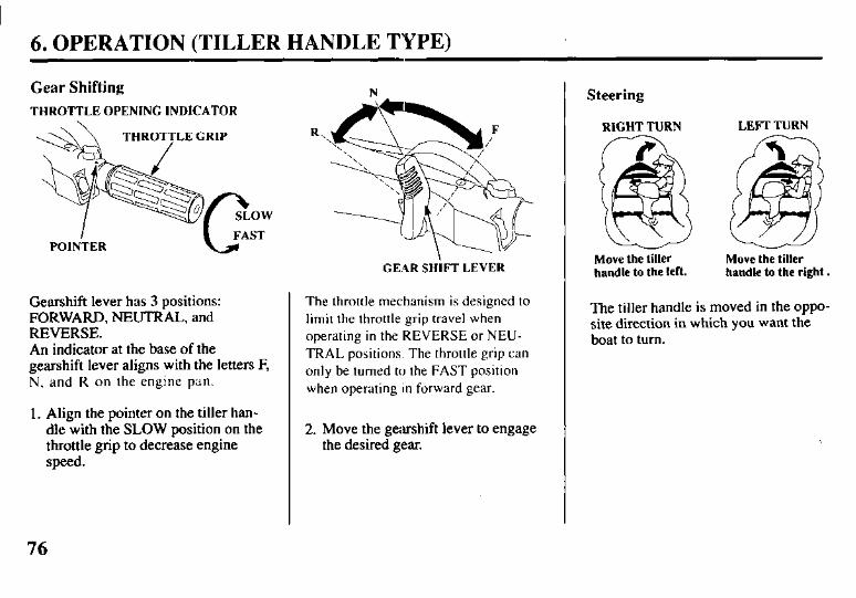
Gear Shifting
THROTTLE OPENING INDICATOR
POINTER
Gearshift lever has 3 positions: FORWARD, NEUTRAL, and REVERSE. An indicator at the base of the gearshift lever aligns with the letters F, N, and R on the engine pan.
1. Align the pointer on the tiller han- dle with the SLOW position on the throttle grip to decrease engine speed.
GEAR SHiFT LEVER
The throttle mechanism is designed to limit the throttle grip travel when operating in the REVERSE or NEU- TRAL positions. The throttle grip can only be turned to the FAST position when operating in forward gear.
2. Move the gearshift lever to engage the desired gear.
Steering
RIGHT TURN LEFl- TURN
Move the tiller Move the tiller handle to the left. handle to the right.
The tiller handle is moved in the oppo- site direction in which you want the boat to turn.
76
6. OPERATION (TILLER HANDLE TYPE)
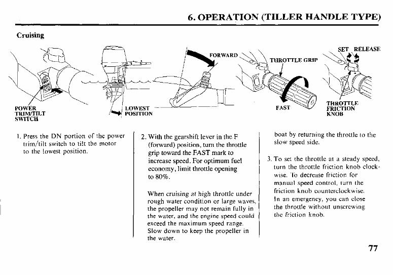
Cruising
SWITCH
I. Press the DN portion of the power trim/tilt switch to tilt the motor to the lowest position.
2. With the gearshift lever in the F (forward) position, turn the throttle grip toward the FAST mark to increase speed. For optimum fuel economy, limit throttle opening to 80%.
When cruising at high throttle under rough water condition or large waves, the propeller may not remain fully in the water, and the engine speed could exceed the maximum speed range. Slow down to keep the propeller in the water.
boat by returning the throttle to the slow speed side.
3. To set the throttle at a steady speed, turn the throttle friction knob clock- wise. To decrease friction for manual speed control, turn the friction knob counterclockwise. In an emergency, you can close the throttle without unscrewing the friction knob.
6. OPERATION (REMOTE CONTROL, TYPE)
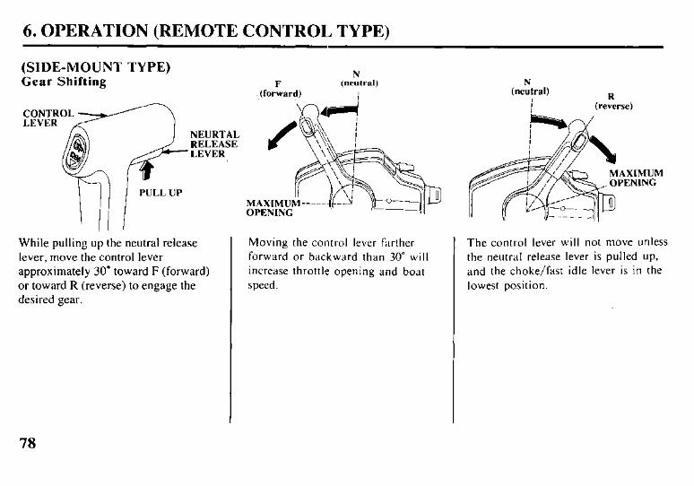
(SIDE-MOUNT TYPE) Gear Shifting F
.jforward)
‘I ,‘I 3 PULL UP
II
While pulling up the neutral release lever, move the control lever approximately 30” toward F (forward) or toward R (reverse) to engage the desired gear.
OPENING
Moving the control lever farther The control lever will not move unless forward or backward than 30” will the neutral release lever is pulled up, increase throttle opening and boat and the choke/fast idle lever is in the speed. lowest position.
(nekal)
i &eke)
MUM ING
78
6. OPERATION (REMOTE CONTROL TYPE)
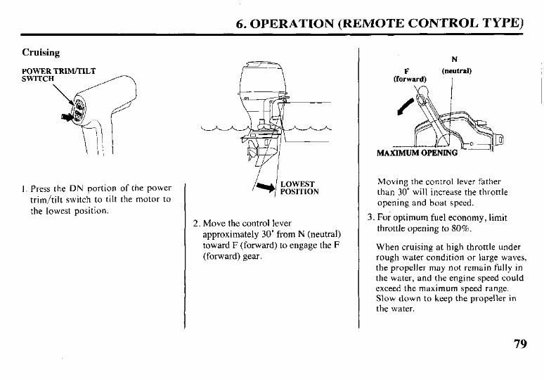
Cruising
POWER TRIM/TILT SWITC
I. Press the DN portion of the power trim/tilt switch to tilt the motor to the lowest position.
LOWEST POSITION
2. Move the control lever approximately 30” from N (neutral) toward F (forward) to engage the F (forward) gear.
N
F (neutral) (forward) I I I
Moving the control lever father than 30” will increase the throttle opening and boat speed.
3. For optimum fuel economy, limit throttle opening to 80%.
When cruising at high throttle under rough water condition or large waves, the propeller may not remain fully in the water, and the engine speed could exceed the maximum speed range. Slow down to keep the propeller in the water.
79
6. OPERATION (REMOTE CONTROL, TYPE)
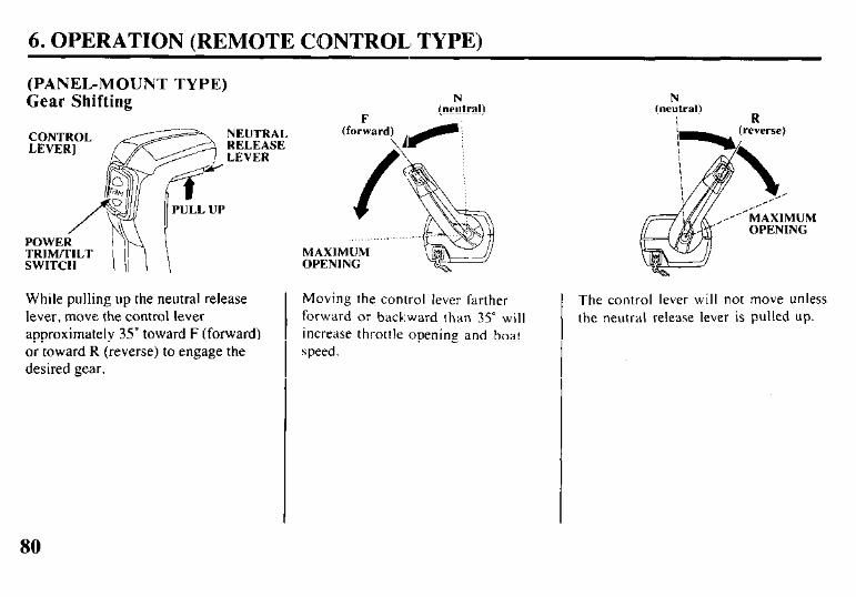
(PANEL-MOUNT TYPE) kear Shifting N
(neutral)
CONTROL LEVER]
A/g=jsp%E?~ (
POWER TRIM/TILT MAXIMUM SWITCH OPENING
While pulling up the neutral release lever, move the control lever approximately 35” toward F (forward) or toward R (reverse) to engage the desired gear.
Moving the control lever farther forward or backward than 35” will increase throttle opening and boat speed.
N (neutral)
R
The control lever will not move unless the neutral release lever is pulled up.
6. OPERATION (REMOTE CONTROL TYPE)
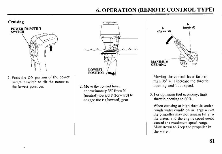
Cruising
I. Press the DN portion of the power trim/tilt switch to tilt the motor to the lowest position. 2. Move the control lever
approximately 35” from N (neutral) toward F (forward) to engage the F (forward) gear.
(forFward)
N (neutral)
MAXIMUM OPENING
Moving the control lever farther than 35” will increase the throttle opening and boat speed.
3. For optimum fuel economy, limit throttle opening to 80%.
When cruising at high throttle under rough water condition or large waves, the propeller may not remain fully in the water, and the engine speed could exceed the maximum speed range. Slow down to keep the propeller in the water.
81
6. OPERATION (REMOTE CONTROL TYPE)
(TOP-MOUNT TYPE) Gear Shifting
SINGLE TYPE
DUAL TYPE
Move the control lever approximately 35” toward F (forward) or toward R (reverse) to engage the desired gear.
OPENING
Moving the control lever farther forward or backward than 35” will increase throttle opening and boat speed.
N (nertral) R
(reikrse)
,’ MAXIMUM OPENING
The control lever will not move unless the neutral release lever is pulled up.
82

6. OPERATION (REMOTE CONTROL TYPE)
Cruising LEFT MOTOR
SINGLE TYPE TRIM/TILT SWITCH RIGHT MOTOR
\ TRIM/TILT SWITCH
POWER TRIM/TILT SWITCH
DUAL TYPE
POWER TRIM/TILT SWITCH
1. Press the DN portion of the power trim/tilt switch to tilt the motor to the lowest position.
If your boat is dual outboard motor type, adjust the trim angle of the right and left motors to be equal using the switches on the control box, as necessary.
2. Move the control lever approximately 35” from N (neutral) toward F (forward) to engage the F (forward) gear.
N
(fcbiard)
(neutral) I I
MAXIMUM OPENING
Moving the control lever farther than 35” will increase the throttle opening and boat speed.
3. For optimum fuel economy, limit throttle opening to 80%.
When cruising at high throttle under rough water condition or large waves, the propeller may not remain fully in the water, and the engine speed could exceed the maximum speed range. Slow down to keep the propeller in the water.
83
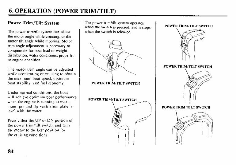
6. OPERATION (POWER TRIM/TILT)
Power Trim/Tilt System
The power trim/tilt system can adjust the motor angle while cruising, or the motor tilt angle while mooring. Motor trim angle adjustment is necessary to compensate for boat load or weight distribution, water conditions, propeller or engine condition.
The motor trim angle can be adjusted while accelerating or cruising to obtain the maximum boat speed, optimum boat stability, and fuel economy.
Under normal conditions, the boat will achieve optimum boat performance when the engine is running at maxi- mum rpm and the ventilation plate is level with the water.
Press either the UP or DN portion of the power trim/tilt switch, and trim the motor to the best position for the cruising conditions.
The power trim/tilt system operates when the switch is pressed, and it stops
when the switch is released.
POWER TRkTILT SWITCH
POWER TRIM/TILT SWITCH
\
POWER TRIM/TILT SWITCH
POWER TRIM/TILT SWITCH
\ 1 POWER TRIM/TILT SWITCH
84
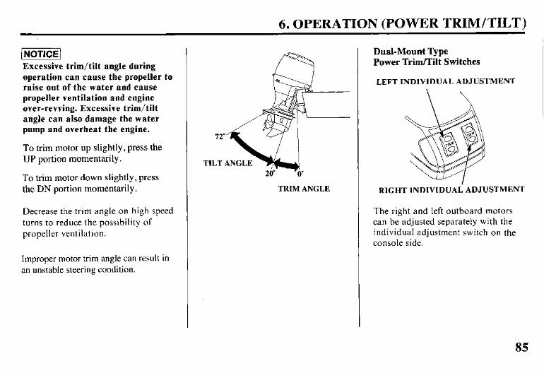
6. OPERATION (POWER TRIM/TILT)
(NOTICE1 Excessive trim/tilt angle during operation can cause the propeller to raise out of the water and cause propeller ventilation and engine over-revving. Excessive trim/tilt angle can also damage the water pump and overheat the engine.
To trim motor up slightly, press the UP portion momentarily.
To trim motor down slightly, press the DN portion momentarily.
Decrease the trim angle on high speed turns to reduce the possibility of propeller ventilation.
Improper motor trim angle can result in an unstable steering condition.
TRIM ANGLE
Dual-Mount Type Power Trim/Tilt Switches
LEFT INDIVIDUAL ADJUSTMENT
RIGHT INDIVIDUAi ADJUSTMENT
The right and left outboard motors can be adjusted separately with the individual adjustment switch on the console side.
85
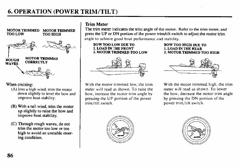
6. OPERATION (POWER TRIM/TILT)
MOTOR TRIMMED MOTOR TRIMMED TOO LOW TOO HIGH
R’OUGH MOTOR TRIMMED
WAVES CORRECTLY
When cruising: (A) Into a high wind, trim the motor
down slightly to level the bow and improve boat stability.
(B) With a tail wind, trim the motor up slightly to raise the bow and improve boat stability.
(C) Through rough waves, do not trim the motor too low or too high to avoid an unstable steer- ing condition.
Trim Meter The trim meter indicates the trim angle of the motor. Refer to the trim meter, and press the UP or DN portion of the power trim/tilt switch to adjust, the motor trim angle to achieve good boat performance and stability.
BOW TOO HIGH DUE TO 1. LOAD IN THE REAR 2. MOTOR TRIMMED TOO HIGH
BOW TOO LOW DUE TO 1. LOAD IN THE FRONT 2. MOTOR TRIMMED TOO LOW
With the motor trimmed low, the trim meter will read as shown. To raise the bow, increase the motor trim angle by pressing the UP portion of the power trim/tilt switch.
With the motor trimmed high, the trim meter will read as shown. To lower the bow, decrease the motor trim angle by pressing the DN portion of the power trim/tilt switch.
86

6. OPERATION (POWER TRIM/TILT)
Power Tilt Switch (Engine Pan)
POWER TILT SWITCH
The power tilt switch located on the engine pan is a convenience switch for tilting the motor for trailering, or performing outboard motor mainte- nance. This power tilt switch should only be operated when the boat is stopped and the engine is off.
Manual Relief Valve
d / MANUAL RELIEF VALVE
POWER (To release)
(To fix)
If the power trim/tilt switch will not tilt the outboard motor, the motor can be manually tilted up or down by operating the manual relief valve. To tilt the outboard motor manually, turn the manual relief valve under the left stem bracket no more than 1 or 2 turns counterclockwise, using a screwdriver.
After tilting the motor, turn the manual relief valve clockwise securely. The manual relief valve must be tightened securely before operating the motor, or the motor could tilt up when operating in reverse.
87
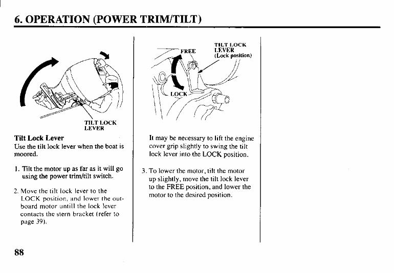
6. OPERATION (POWER TRIM/TILT)
TILT LOCK LEVER
Tilt Lock Lever Use the tilt lock lever when the boat is moored.
1. lilt the motor up as far as it will go using the power trim/tilt switch.
2. Move the tilt lock lever to the LOCK position, and lower the out- board motor until1 the lock lever contacts the stern bracket (refer to page 39).
TILT I.OCK
It may be necessary to lift the engine cover grip slightly to swing the tilt lock lever into the LOCK position.
3. To lower the motor, tilt the motor up slightly, move the tilt lock lever to the FREE position, and lower the motor to the desired position.
88
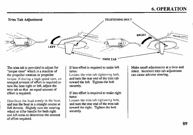
6. OPERATION
Trim Tab Adjustment TIGHTENING BOLT
The trim tab is provided to adjust for “torque steer” which is a reaction of the propeller rotation or propeller torque. If during a high speed turn, an unequal amount of effort is required to turn the boat right or left, adjust the trim tab so that an equal amount of effort is required.
Distribute the load evenly in the boat, and run the boat in a straight course at full throttle. Slightly turn the steering wheel or tiller handle for both right and left turns to determine the amount of effort required.
If less effort is required to make left turns: Loosen the trim tab tightening bolt, and turn the rear end of the trim tab toward the left. Tighten the bolt securely.
If less effort is required to make right turns: Loosen the trim tab tightening bolt, and turn the rear end of the trim tab toward the right. Tighten the bolt securely.
Make small adjustments at a time and retest. Incorrect trim tab adjustment can cause adverse steering.
89
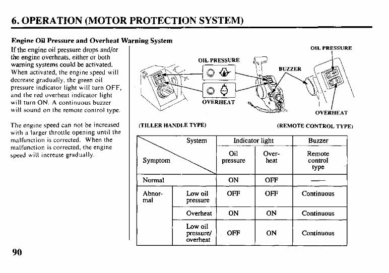
6. OPERATION (MOTOR PROTECTION SYSTEM)
Engine Oil Pressure and Overheat Warning System If the engine oil pressure drops and/or the engine overheats, either or both warning systems could be activated. When activated, the engine speed will decrease gradually, the green oil pressure indicator light will turn OFF, and the red overheat indicator light will turn ON. A continuous buzzer will sound on the remote control type.
The engine speed can not be increased with a larger throttle opening until the malfunction is corrected. When the malfunction is corrected, the engine speed will increase gradually.
(TILLER HANDLE TYPE) (REMOTE CONTROL TYPE)
Indicator light Buzzer
Oil Over- Remote pressure heat control
type
Normal ON OFF
Abnor- Low oil OFF OFF Continuous ma1 pressure
Overheat ON ON Continuous
Low oil pressure/ OFF ON Continuous overheat
90
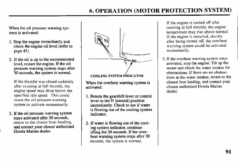
6. OPERATION (MOTOR PROTECTION SYSTEM)
When the oil pressure warning sys- tems is activated:
1. Stop the engine immediately and check the engine oil level (refer to page 45).
2. If the oil is up to the recommended level, restart the engine. If the oil pressure warning system stops after 30 seconds, the system is normal.
If the throttle was closed suddenly after cruising at full throttle, the engine speed may drop below the specified idle speed. This could cause the oil pressure warning system to activate momentarily.
3. If the oil pressure warning system stays activated after 30 seconds, return to the closest boat landing, and contact your closest authorized Honda Marine dealer.
COOLING SYSTEM IiDICATOR
When the overheat warning system is activated:
1. Return the gearshift lever or control lever to the N (neutral) position immediately. Check to see if water is flowing out of the cooling system indicator.
2. If water is flowing out of the cool- ing system indicator, continue idling for 30 seconds. If the over- heat warning system stops after 30 seconds, the system is normal.
If the engine is turned off after running at full throttle, the engine temperature may rise above normal. If the engine is restarted, shortly after being turned off, the overheat warning system could be activated momentarily.
3. If the overheat warning system stays activated, stop the engine. Tilt up the motor and check the water intakes for obstructions. If there are no obstruc- tions at the water intakes, return to the closest boat landing, and contact your closest authorized Honda Marine dealer.
91
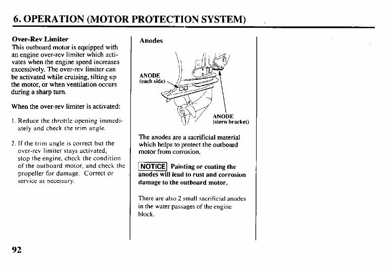
6. OPERATION (MOTOR PROTECTION SYSTEM)
Over-Rev Limiter This outboard motor is equipped with an engine over-rev limiter which acti- vates when the engine speed increases excessively. The over-rev limiter can be activated while cruising, tilting up the motor, or when ventilation occurs during a sharp turn.
When the over-rev limiter is activated:
I. Reduce the throttle opening immedi- ately and check the trim angle.
2. If the trim angle is correct but the over-rev limiter stays activated, stop the engine, check the condition of the outboard motor, and check the propeller for damage. Correct or service as necessary.
Anodes
(stern bracket)
The anodes are a sacrificial material which helps to protect the outboard motor from core:osion.
-1 Painting or coating the
anodes will lead to rust and corrosion
damage to the outboard motor.
There are also 2 small sacrificial anodes in the water passages of the engine block.
92

6. OPERATION
Shallow Water Operation
Excessive trim/tilt angle during
operation can cause the propeller to
raise out of the water and cause
propeller ventilation and engine
over-revving. Excessive trim/tilt
angle can also damage the water
pump and overheat the engine.
When operating in shallow water, tilt the motor up to prevent the propeller and gear case from hitting the bottom With the motor tilted up, operate the engine at low speed.
Monitor the cooling system indicator for water discharge. Be sure that the motor is not tilted so high that the water intakes are out of the water.
93
6. OPERATION
High Altitude Operation
At high altitude, the standard carburetor air-fuel mixture will be too rich. Performance will decrease. and fuel con- sumption will increase. A very rich mixture will also foul the spark plugs and cause hard starting.
High altitude performance can be improved by specific modifications to the carburetors. If you always operate your outboard at altitudes above 5,000 feet (1,500 meters) have an authorized Honda Marine dealer perform this car- buretor modification.
Even with carburetor modification. engine horsepower will decrease about 3.5% for each 1,000 foot (300 meter) increase in altitude. The effect of altitude on horsepower will be greater than this if no carburetor modification is made.
1 NOTICEI When the carburetors have been modified for higt
altitude operation, the air-fuel mixture will be too
lean for low altitude use. Operation at altitndes
below 5,000 feet (1,500 meters) with modified carburetors may cause the engine to overheat and
result in serious engine damage. For use at low
altitudes, have an authorized Honda Marine dealer
return the carburetors to original factory
specifications if modified.
94

7. STOPPING THE ENGINE (TILLER HANDLE TYPE)
Emergency Engihe Stop
EMERGENCY STOP SWITCH
EMERGENCY STOP SWITCH LANYARD
EMEIibENCY STOP SWITCH CLIP
Disengage the emergency stop switch clip from the emergency stop switch by pulling the emergency stop switch lan- yard.
It is a good idea to stop the engine with the emergency stop switch lanyard from time to time to be sure that the switch is operating properly.
Normal Engine Stop
THROTTLE GRIP
(Nesrral)
GEAR SHIFT LEVER
I. Turn the throttle grip to SLOW position, and move the gearshift lever to N (neutral).
IGNITION SWITCH
2. Turn the ignition switch to the OFF position.
3. When the boat is not in use, remove and store the ignition switch key.
95
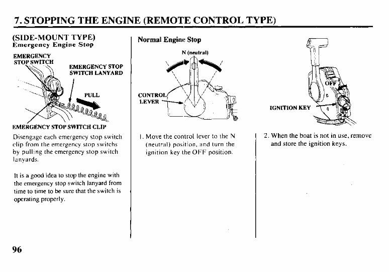
7. STOPPING THE ENGINE (REMOTE CONTROL TYPE)
(SIDE-MOUNT TYPE) Emergency Engine Stop
EMERr-“!‘!CF’
EMERGENCY STOP SWITCH LANYARD
bl PULL
EMERGENCY STOP SWITCH CLIP
Disengage each emergency stop switch clip from the emergency stop switchs by pulling the emergency stop switch lanyards.
It is a good idea to stop the engine with the emergency stop switch lanyard from time to time to be sure that the switch is operating properly.
Normal Engine Stop
N (neutral)
I. Move the control lever to the N (neutral) position, and turn the ignition key the OFF position.
IGNITION KEY
2. When the boat is not in use, remove and store the ignition keys.
96
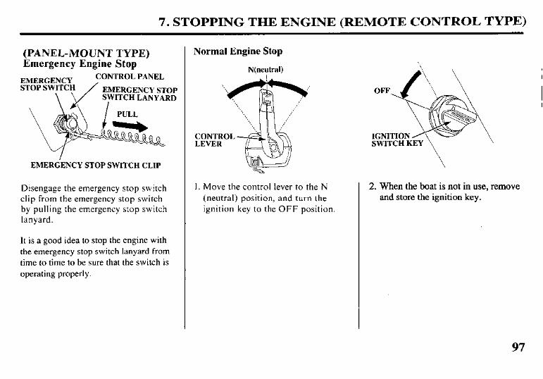
7. STOPPING THE ENGINE (REMOTE CONTROL TYPE)
(PANEL-MOUNT TYPE) Emergency Engine Stop
EMERGENC STOP SWITC
ONTROL PANEL
EMERGENCY STOP SWITCH LANYARD
EMERdENCY STOP SWITCH CLIP
Disengage the emergency stop switch clip from the emergency stop switch by pulling the emergency stop switch lanyard.
It is a good idea to stop the engine with the emergency stop switch lanyard from time to time to be sure that the switch is operating properly.
Normal Engine Stop
N(neutral)
I. Move the control lever to the N (neutral) position, and turn the ignition key to the OFF position.
2. When the boat is not in use, remove and store the ignition key.
97
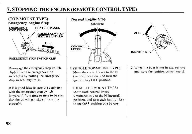
7. STOPPING THE ENGINE (REMOTE CONTROL TYPE)
(TOP-MOUNT TYPE) Emergency Engine Stop EMERGENCY CONTROL PANEL STOP SWITCH
\ EMERGENCY STOP
\ \J SEITCH LANYARD
\
EMERGENCY STOP SWITCH CLIP
Disengage the emergency stop switch clip(s) from the emergency stop switch(es) by pulling the emergency stop switch lanyard(s).
It is a good idea to stop the engine(s) with the emergency stop switch lanyard(s) from time to time to be sure that the switch(es) is(are) operating properly.
Normal Engine Stop N(neutral)
I. (SINGLE TOP-MOUNT TYPE) Move the control lever to the N (neutral) position, and turn the ignition key OFF position.
(DUAL TOP-MOUNT TYPE) Move both control levers simulteneously to the N (neutral) position, and turn each ignition key to the OFF position one by one.
2. When the boat is not in use, remove and store the ignition switch key(s).
98
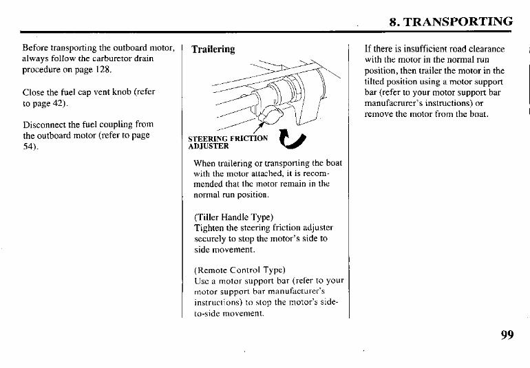
8. TRANSPORTING
Before transporting the outboard motor, always follow the carburetor drain procedure on page 128.
Close the fuel cap vent knob (refer to page 42).
Disconnect the fuel coupling from the outboard motor (refer to page 54).
Trailering
I /
STEERING FRICTION ADJUSTER
When trailering or transporting the boat with the motor attached, it is recom- mended that the motor remain in the normal run position.
(Tiller Handle Type) Tighten the steering friction adjuster securely to stop the motor’s side to side movement.
(Remote Control Type) Use a motor support bar (refer to your motor support bar manufacturer’s instructions) to stop the motor’s side- to-side movement.
If there is insufficient road clearance with the motor in the normal run position, then trailer the motor in the tilted position using a motor support bar (refer to your motor support bar manufacrurer’s instructions) or remove the motor from the boat.
99
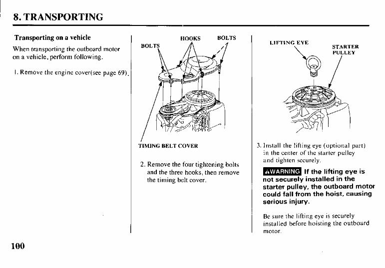
I ’ 8. TRANSPORTING
Transporting on a vehicle
When transporting the outboard motor on a vehicle, perform following.
I. Remove the engine cover(see page 69)
IIOOKS BOLTS
BOLTS
TIMING BELT COVER
2. Remove the four tightening bolts and the three hooks, then remove the timing belt cover.
LIFTING EYE \ STARTER
PULLEY
3. Install the lifting eye (optional part) in the center of the starter pulley and tighten securely.
B If the lifting eye is not securely installed in the starter pulley, the outboard motor could fall from the hoist, causing serious injury.
Be sure the lifting eye is securely installed before hoisting the outboard motor.
100
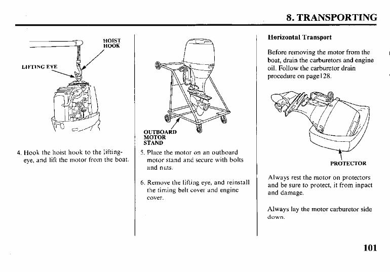
8. TRANSPORTING
LIFTING E
4. Hook the hoist hook to the lifting- eye, and lift the motor from the boat.
STAND
5. Place the motor on an outboard motor stand and secure with bolts and nuts.
6. Remove the lifting eye, and reinstall the timing belt cover and engine cover.
Horizontal Transport
Before removing the motor from the boat, drain the carburetors and engine oil. Follow the carburetor drain procedure on page128.
PRdTECTOR
Always rest the motor on protectors and be sure to protect, it from inpact and damage.
Always lay the motor carburetor side down.
101
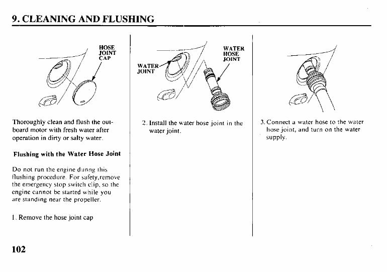
9. CLEANING AND FLUSHING
Thoroughly clean and flush the out- board motor with fresh water after operation in dirty or salty water.
Flushing with the Water Hose Joint
Do not run the engine dunng this flushing procedure. For safety,remove the emergency stop switch clip, so the engine cannot be started while you are standing near the propeller.
1. Remove the hose joint cap
--- H
WATER JOINT
6
2. Install the water hose joint in the water joint.
3. Connect a water hose to the water hose joint, and turn on the water
supply.
102

9. CLEANING AND FLUSHING
4. Make sure that the water comes out from the exhaust port.
5. After flushing, remove the water hose joint and re-install the hose joint cap.
If using a headphone-type flush kit, temporarily cover the water intakes with duct tape.
103
10. MAINTENANCE
THE IMPORTANCE OF MAINTENANCE
Good maintenance is essential for safe, economical, and trouble-free opera- tion. It will also help reduce pollution.
m Improper mainte- .=
nance, or failure to correct a problem before operation, can cause a malfunction in which you can be seriously hurt or killed.
Always follow the inspection and maintenance recommenda- tions and schedules in this owner’s manual.
To help you properly care for your outboard motor, the following pages include a maintenance schedule, routine inspection procedures, and simple maintenance procedures using basic hand tools. Other service tasks that are more difficult, or require special tools, are best handled by
104
professionals and are normally per- formed by a Honda technician or other qualified mechanic.
The maintenance schedule applies to normal operating conditions. If you operate your outboard motor under unusual conditions, consult your servicing dealer for recommendations applicable to your individual needs and use.
Maintenance,. replacement, or repair of the emission control devices and systems may be performed by any marine engine repair establishment or individual, using parts that are “certified” to EPA standards.
MAINTENANCE SAFETY
Some of the most important sefcty precautions follow. However, we cannot warn you of every conceivable hazard that can arise in performing maintenance. Only you can decide whether or not you should perform a given task.
m Failure to properly L -
follow maintenance instruc- tions and precautions can cause you to be seriously hurt or killed.
Always follow the procedures and precautions in this owner’s manual.
10. MAINTENANCE
Safety Precautions
l Make sure the engine is off before you begin any maintenance or repairs. This will eliminate several potential hazards:
-Carbon monoxide poisoning from engine exhaust. Be sure there is adequate ventila- tion whenever you operate the engine.
- Burns from hot parts. Let the engine cool before touch- ing.
- Injury from moving parts. Do not run the engine unless instructed to do so.
l Read the instructions before you begin, and make sure you have the tools and skills required.
l To reduce the possibility of fire or explosion, be careful when working around gasoline. Use only a non- flammable solvent, not gasoline to clean parts. Keep cigarettes, sparks, and flames away from all fuel- related parts.
Remember that an authorized Honda Marine dealer knows your outboard motor best and is fully equipped to maintain and repair it.
To ensure the best quality and reliability, use only new, genuine Honda parts or their equivalents for repair and replacement.
EMISSION CONTROL SYSTEM INFORMATION
Source of Emissions
The combustion process produces carbon monoxide, oxides of nitrogen, and hydrocarbons. Control of hydro- carbons and oxides of nitrogen is very important because, under certain conditions, they react to form photo- chemical smog when subjected to sunlight.
Honda utilizes lean carburetor settings and other systems to reduce the emissions of oxides of nitrogen and hydrocarbons.
105
10. MAINTENANCE
The U.S. Clean Air Act
EPA regulations require all manufac- tures to furnish written instructions describing the operation and mainte- nance of emission control systems.
The following instructions and proce- dures must be followed in order to keep the emissions from your Honda engine within the emission standards.
Tampering and Altering
Tampering with or altering the emis- sion control system may increase emissions beyond the legal limit. Among those acts that constitute tampering are:
l Removal or alteration of any part of the intake, fuel , or exhaust systems.
l Alterations that would cause the engine to operate outside its design parameters.
106
Problems That May Affect Emissions
If you are aware of any of the following symptoms, have your engine inspected and repaired by your servic- ing dealer.
l Head starting or stalling after starting.
l Rough idle.
l Misfiring or backfiring under load.
l Afterburining (backfiring).
l Black exhaust smoke or high fuel consumption.
10. MAINTENANCE
Replacement Parts
The emission control systems on your Honda engine were designed, built, and certified to conform with EPA emission regulations. We recommend the use of genuine Honda parts whenever you have maintenance done. These original-design replacement parts are manufactured to the same standards as the original parts, so you can be confident of their performance. The use of replacement parts that are not of the original design and quality may impair the effectiveness of your emission control system.
A manufacturer of an aftermarket part assumes the responsibility that the part will not adversely affect emission performance. The manufacturer or rebuilder of the part must certify that use of the part will not result in a failure of the engine to comply with emission regulations.
Maintenance
Follow the maintenance schedule on page 109. Remember that this schedule is based on the assumption that your machine will be used for its designed purpose. Sustained high-load or high- temperature operation, or use in unusually wet or dusty conditions, will require more frequent service.
107
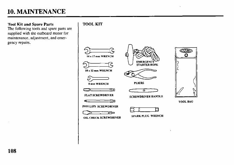
10. MAINTENANCE
Tool Kit and Spare Parts The following tools and spare parts are supplied with the outboard motor for maintenance, adjustment, and emer- gency repairs.
TOOL KIT
14 x 17 mm WRENCH
-3 10 x 12 mm WRENCH
)
8 mm WRENCH
FLAT SCREWDRIVER
-a
PHILLIPS SCREWDRIVER
-a
OIL CHECK SCREWDRIVER
PLIERS
c cl 2
SCREWDRIVER HANDLE
TOOL BAG
SPARK PLUG WRENCH
108

10. MAINTENANCE
MAINTENANCE SCHEDULE
REGULAR SERVICE PERIOD (3) FIRST EVERY EVERY EVERY
109
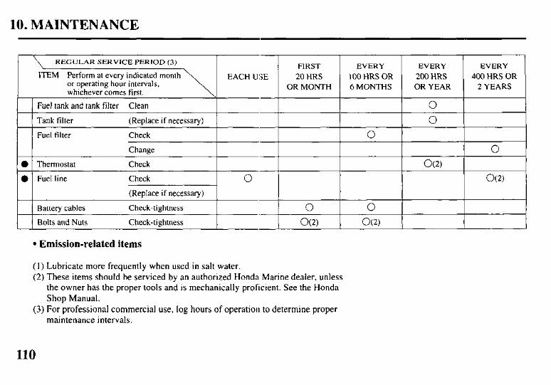
10. MAINTENANCE
ITEM Perform at every indicated month
Fuel tank and tank filter
[ Tank filter (Replace if necessary) 1
Fuel filter Check
Change
0 1 Thermostat Check
0 Fuel line
-1 O
Battery cables Check-tightness I 1 Bolts and Nuts Check-tiehtness I
FIRST
20 HRS
OR MONTH
0
l Emission-related items
(I) Lubricate more frequently when used in salt water. (2) These items should be serviced by an authorized Honda Marine dealer, unless
the owner has the proper tools and is mechanically proficient. See the Honda Shop Manual.
(3) For professional commercial use, log hours of operation to determine proper maintenance intervals.
EVERY EVERY EVERY
100 HRS OR 200 HRS 400 HRS OR 6 MONTHS OR YEAR 2 YEARS
0
0
0
0
O(2)
O(2)
110
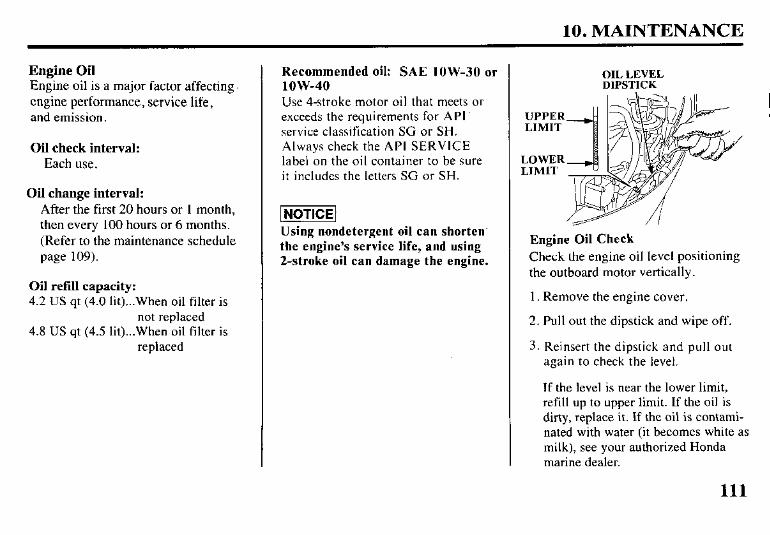
10. MAINTENANCE
Engine Oil Engine oil is a major factor affecting engine performance, service life, and emission.
Oil check interval: Each use.
Oil change interval: After the first 20 hours or 1 month, then every 100 hours or 6 months. (Refer to the maintenance schedule page 109).
Oil refill capacity: 4.2 US qt (4.0 lit)...When oil filter is
not replaced 4.8 US qt (4.5 lit)...When oil filter is
replaced
Recommended oil: SAE low-30 or low-40 Use 4-stroke motor oil that meets or exceeds the requirements for API’ service classification SC or SH. Always check the API SERVICE label on the oil container to be sure it includes the letters SG or SH.
Using nondetergent oil can shorten. the engine’s service life, and using 2-stroke oil can damage the engine.
OIL LEVEL DIPSTICK
UPPER LIMIT
LOWER LIMIT
Engine Oil Check Check the engine oil level positioning the outboard motor vertically.
1. Remove the engine cover.
2. Pull out the dipstick and wipe off.
3. Reinsert the dipstick and pull out again to check the level.
If the level is near the lower limit, refill up to upper limit. If the oil is dirty, replace it. If the oil is contami- nated with water (it becomes white as milk), see your authorized Honda marine dealer.
111
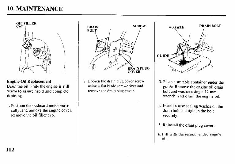
10. MAINTENANCE
OIL FILLER CAP
I
\
\
i
Engine Oil Replacement Drain the oil while the engine is still warm to assure rapid and complete draining.
I. Position the outboard motor verti- cally, and remove the engine cover. Remove the oil filler cap.
DRAIN SCREW
DRAIN PLUG COVER
2. Loosen the drain plug cover screw using a flat blade screwdriver and remove the drain plug cover.
WASHER DRAIN BOLT
\ I
3. Place a suitable container under the guide. Remove the engine oil drain bolt and washer using a 12 mm wrench, and drain the engine oil.
4. Install a new sealing washer on the drain bolt and tighten the bolt securely.
5. Reinstall the drain plug cover.
6. Fill with the recommended engine oil.
112
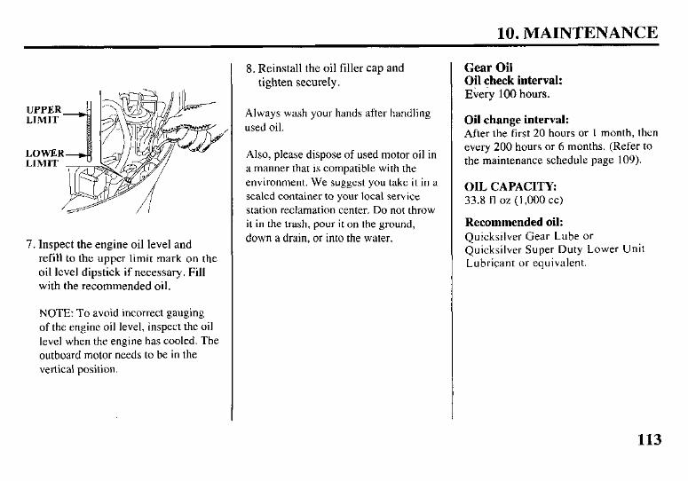
10. MAINTENANCE
7. Inspect the engine oil level and refill to the upper limit mark on the oil level dipstick if necessary. Fill with the recommended oil.
NOTE: To avoid incorrect gauging of the engine oil level, inspect the oil level when the engine has cooled. The outboard motor needs to be in the vertical position.
8. Reinstall the oil filler cap and tighten securely.
Always wash your hands after handling used oil.
Also, please dispose of used motor oil in a manner that is compatible with the environment. We suggest you take it in a sealed container to your local service station reclamation center. Do not throw it in the trash, pour it on the ground, down a drain, or into the water.
Gear Oil Oil check interval: Every 100 hours.
Oil change interval: After the first 20 hours or 1 month, then every 200 hours or 6 months. (Refer to the maintenance schedule page 109).
OIL CAPACITY: 33.8 fl oz (1,000 cc)
Recommended oil: Quicksilver Gear Lube or Quicksilver Super Duty Lower Unit Lubricant or equivalent.
113
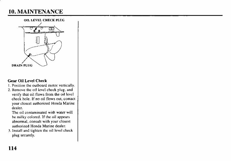
10. MAINTENANCE
OIL LEVEL CHECK PLUG
Gear Oil Level Check I. Position the outboard motor vertically. 2. Remove the oil level check plug, and
verify that oil flows from the oil level check hole. If no oil flows out, contact your closest authorized Honda Marine dealer. The oil contaminated with water will be milky colored. If the oil appears abnormal, consult with your closest authorized Honda Marine dealer.
3. Install and tighten the oil level check plug securely.
114

10. MAINTENANCE
Spark Plugs To ensure proper engine operation, the spark plugs must be properly gapped and free of deposits.
Check-replace interval: After the first 20 hours or 1 month then every 200 hours or 6 months (Refer to the maintenance schedule page 109).
Recommended spark plug: DR7EA (NGK), X22ESR-U (DENSO) Use only the recommended spark plugs or equivalent.
m Spark plugs which have an improper heat range may cause engine damage.
I. Allow the engine to cool. The spark plugs will be hot if the engine has been running.
2. Remove the engine cover.
WRENCH 17 mm WRENCH
3. Disconnect the spark plug caps from the spark plugs.
4. Use the spark plug wrench and I7 mm wrench supplied in the tool kit to remove the spark plugs.
5. Check the spark plugs. Replace the spark plugs if there is apparent wear, or if the insulators are cracked or chipped. Clean the spark plugs with a wire brush if they are to be reused.
0.024-0.028 in
(0.6-0.7 mm)
6. Measure the plug gaps with a spark
Plug gap iwis
The gaps should be 0.024-0.028 in (0.6-0.7 mm). Correct as necessary by carefully bending the side elec- trode.
115
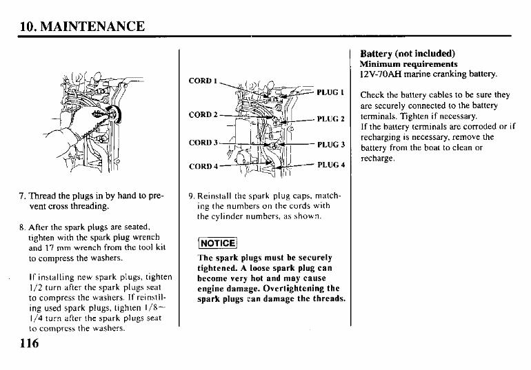
10. MAINTENANCE
7. Thread the plugs in by hand to pre- vent cross threading.
8. After the spark plugs are seated, tighten with the spark plug wrench and 17 mm wrench from the tool kit to compress the washers.
If installing new spark plugs, tighten l/2 turn after the spark plugs seat to compress the washers. If reinstll- ing used spark plugs, tighten l/8- 1/4 turn after the spark plugs seat to compress the washers.
9. Reinstall the spark plug caps, match- ing the numbers on the cords with the cylinder numbers, as shown.
The spark plugs must be securely
tightened. A loose spark plug can
become very hot and may cause
engine damage. Overtightening the
spark plugs can damage the threads.
Battery (not included) Minimum requirements 12V-70AH marine cranking battery.
Check the battery cables to be sure they are securely connected to the battery terminals. Tighten if necessary. If the battery terminals are corroded or if recharging is necessary, remove the battery from the boat to clean or recharge.
116
10. MAINTENANCE
To protect the battery from mechani- cal damage and to prevent the bat- tery from falling or tipping over, the battery must be:
l Installed in the correct size corro- sion-resistant battery box.
l Properly secured in the boat.
l Secured in a location free from di- rect sunlight and water spray.
l Secured away from the fuel tank to avoid potential sparks near the fuel tank.
1. Install the battery in the battery box.
2. Connect the positive (+) battery cable first, then connect the nega- tive (-) battery cable. Tighten the cable nuts securely.
3. Coat the battery terminals and ca- ble ends with marine anticor- rosion grease.
4. Put the cover on the battery box, and secure the battery box to the boat.
117
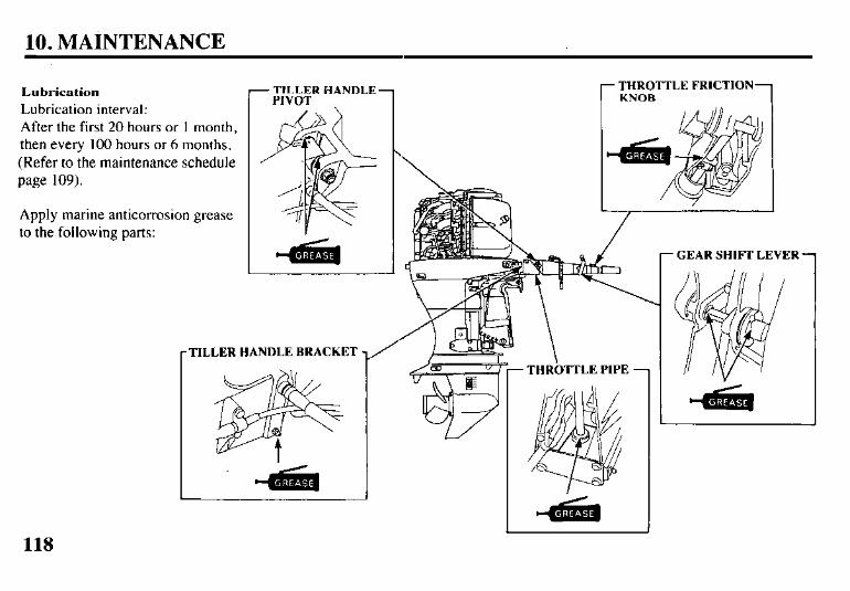
10. MAINTENANCE
Lubrication Lubrication interval: r TILLER HANDLE
PIVOT /\, \ 1
After the first 20 hours or I month, then every 100 hours or 6 months. (Refer to the maintenance schedule page 109).
Apply marine anticorrosion grease to the following parts:
-TILLER
- THROTTLE FRICTION- KNOB
HANDLE BRACKET /
- THRi3TTLE PIPE 7
- GEAR SHIFI. LEVER 1
118
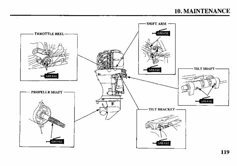
10. MAINTENANCE
- THROTTLE REEL
1 /
- PROPELLR SHAFT 1
- SHIFT ARM -
- TILT BRACKET -
- TILT SHAFT
119

10. MAINTENANCE
THROTTLE ARM/ r SHIFT SHAFT 1 -CHOKE ARM -
CHOKE KNOB -
SWIVEL CASE
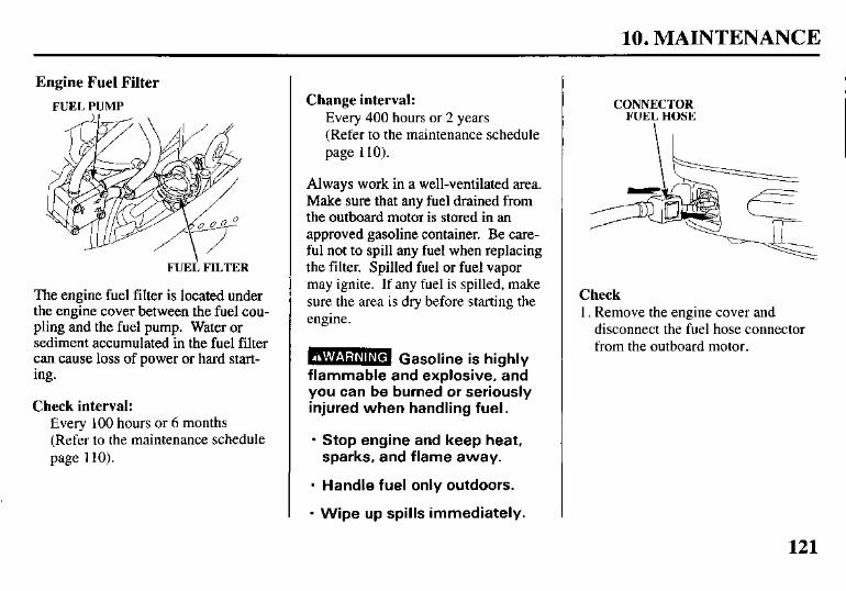
10. MAINTENANCE
Engine Fuel Filter
FUEL PUMP
FUEi FILTER
The engine fuel filter is located under the engine cover between the fuel cou- pling and the fuel pump. Water or sediment accumulated in the fuel filter can cause loss of power or hard start- ing.
Check interval: Every 100 hours or 6 months (Refer to the maintenance schedule page 110).
Change interval: Every 400 hours or 2 years (Refer to the maintenance schedule page 1 IO).
Always work in a well-ventilated area. Make sure that any fuel drained from the outboard motor is stored in an approved gasoline container. Be care- ful not to spill any fuel when replacing the filter. Spilled fuel or fuel vapor may ignite. If any fuel is spilled, make sure the area is dry before starting the engine.
B Gasoline is highly flammable and explosive,gnd you can be burned or seriously injured when handling fuel.
l Stop engine and keep heat, sparks, and flame away.
l Handle fuel only outdoors.
l Wipe up spills immediately.
CONNECTOR
FUEY HoSE
Check 1. Remove the engine cover and
disconnect the fuel hose connector from the outboard motor.
121
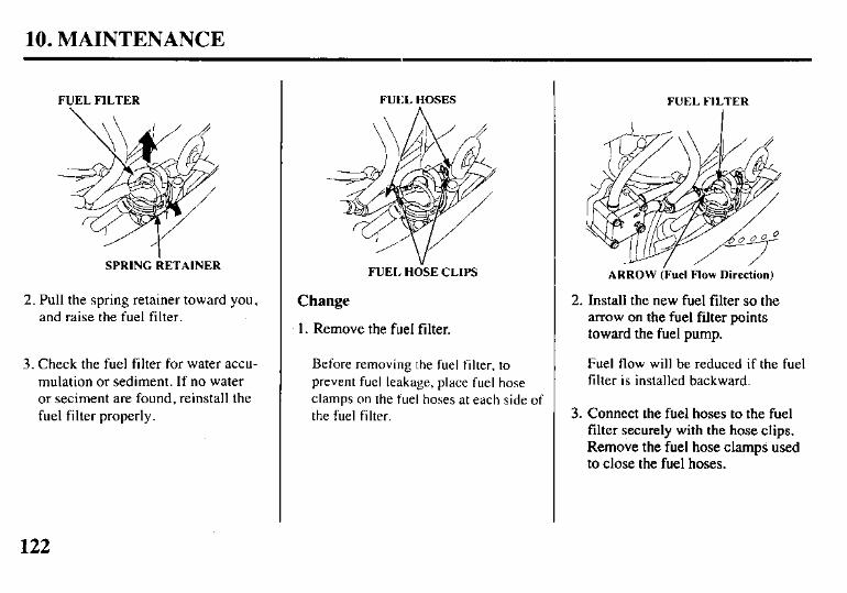
10. MAINTENANCE
FUEL FILTER
SPRING RETAINER
2. Pull the spring retainer toward you, and raise the fuel filter.
3. Check the fuel filter for water accu- mulation or sediment. If no water or seciment are found, reinstall the fuel filter properly.
FUt:L HOSES
FUEL H&E CLIPS
Change
1. Remove the fuel filter.
Before removing the fuel filter, to prevent fuel leakage, place fuel hose clamps on the fuel hoses at each side of the fuel filter.
FUEL FILTER
ARROW (Fuel Flow Direction)
2. Install the new fuel filter so the arrow on the fuel filter points toward the fuel pump.
Fuel flow will be reduced if the fuel filter is installed backward.
3. Connect the fuel hoses to the fuel filter securely with the hose clips. Remove the fuel hose clamps used to close the fuel hoses.
122
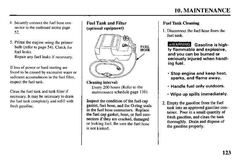
10. MAINTENANCE
4. Securely connect the fuel hose con- nector to the outboard motor page 52.
5. Prime the engine using the primer bulb (refer to page 54). Check for fuel leaks. Repair any fuel leaks if necessary.
If loss of power or hard starting are found to be caused by excessive water or sediment accumulation in the fuel filter, inspect the fuel tank.
Clean the fuel tank and tank filter if necessary. It may be necessary to drain the fuel tank completely and refill with fresh gasoline.
Fuel Tank and Filter (optional equipment)
Cleaning interval: Every 200 hours (Refer to the maintenance schedule page 110).
Inspect the condition of the fuel cap gasket, fuel hose, and the O-ring seals in the fuel hose connectors. Replace the fuel cap gasket, hose, or fuel con- nectors if they are cracked, damaged or leaking fuel. Be sure the fuel hose is not kinked.
Fuel Tank Cleaning
1. Disconnect the fuel hose from the fuel tank.
B Gasoline is high- ly flammable and explosive, and you can be burned or seriously injured when handl- ing fuel.
l Stop engine and keep heat, sparks, and flame away.
l Handle fuel only outdoors.
l Wipe up spills immediately.
2. Empty the gasoline from the fuel tank into an approved gasoline con- tainer. Pour in a small quantity of fresh gasoline, and clean the tank thoroughly. Drain and dispose of the gasoline properly.
123
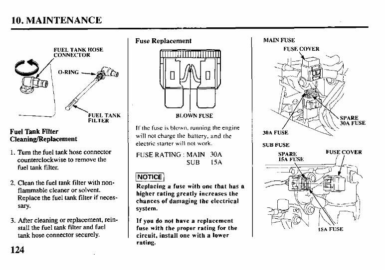
10. MAINTENANCE
FUEL TANK HOSE CONNECTOR
FUEL TANK FILTER
Fuel Tank Filter Cleaning/Replacement
1. Turn the fuel tank hose connector counterclockwise to remove the fuel tank filter.
2. Clean the fuel tank filter with non- flammable cleaner or solvent. Replace the fuel tank filter if neces- sary*
3. After cleaning or replacement, rein- stall the fuel tank filter and fuel tank hose connector securely.
Fuse Replacement
BLOWN FUSE
If the fuse is blown, running the engine will not charge the battery, and the electric starter will not work.
FUSE RATING : MAIN 30A SUB 15A
Replacing a fuse with one that has a
higher rating greatly increases the
chances of damaging the electrical
system.
If you do not have a replacement fuse with the proper rating for the
circuit, install one with a lower rating.
MAIN FUSE
FUSE COVER
SUB FUSE
SPARE
124
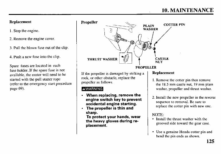
10. MAINTENANCE
Replacement
1. Stop the engine.
2. Remove the engine cover.
3. Pull the blown fuse out of the clip.
4. Push a new fuse into the clip.
Spare fuses are located in each fuse holder. If the spare fuse is not available, the motor will need to be started with the pull starter rope (refer to the emergency start procedure page 69).
Propeller
THRUST
PROPELLER
If the propeller is damaged by striking a rock, or other obstacle, replace the propeller as follows.
-
l When replacing, remove the engine switch key to prevent accidental engine starting.
l The propeller is thin and sharp. To protect your hands, wear the heavy gloves during re- placement.
PIN
Replacement
1. Remove the cotter pin then remove the 18.5 mm castle nut, 19 mm plain washer, propeller and thrust washer.
2. Install the new propeller in the reverse sequence to removal. Be sure to replace the cotter pin with new one.
NOTE: l Install the thrust washer with the
grooved side toward the gear case.
l Use a genuine Honda cotter pin and bend the pin ends as shown.
125
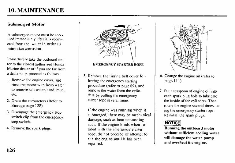
10. MAINTENANCE
Submerged Motor
A submerged motor must be serv- iced immediately after it is recov- ered from the water in order to minimize corrosion.
Immediately take the outboard mo- tor to the closest authorized Honda Marine dealer or if you are far from a dealership, proceed as follows:
1. Remove the engine cover. and rinse the motor with fresh water to remove salt water, sand, mud, etc.
2. Drain the carburetors (Refer to Storage page 128).
3. Disengage the emergency stop switch clip from the emergency stop switch.
4. Remove the spark plugs.
EMERGENCY STARTER.ROPE
5. Remove the timing belt cover fol- lowing the emergency starting procedure (refer to page 69) and remove the water from the cylin- ders by pulling the emergency starter rope several times.
If the engine was running when it submerged, there may be mechanical damage, such as bent connecting rods. If the engine binds when ro- tated with the emergency starter rope, do not proceed or attempt to run the engine until it has been repaired.
6. Change the engine oil (refer to page III).
7. Put a teaspoon of engine oil into each spark plug hole to lubricate the inside of the cylinders. Then rotate the engine several times, us- ing the emergency starter rope. Reinstall the spark plugs.
piETiE] Running the outboard motor
without sufkient cooling water
will damage the water pump
and overheat the engine.
126
10. MAINTENANCE
8. Engage the emergency stop switch clip with the emergency stop switch, and attempt to start the engine (be sure the water level is at least 2 inches above the antiventilation plate).
l If the engine fails to start, re- move the spark plugs, clean and dry the electrodes, then re- install the spark plugs and at- tempt to start the engine again.
l If the engine starts, and no me- chanical damage is evident, continue to run the engine for a l/2 hour or longer.
l If there was water in the engine crankcase, or the drained used engine oil showed signs of water contamination, then a second engine oil change should be performed after running the engine for a l/2 hour.
9. Take the outboard motor to your closest authorized Honda Marine dealer for inspection and service as soon as possible.
127
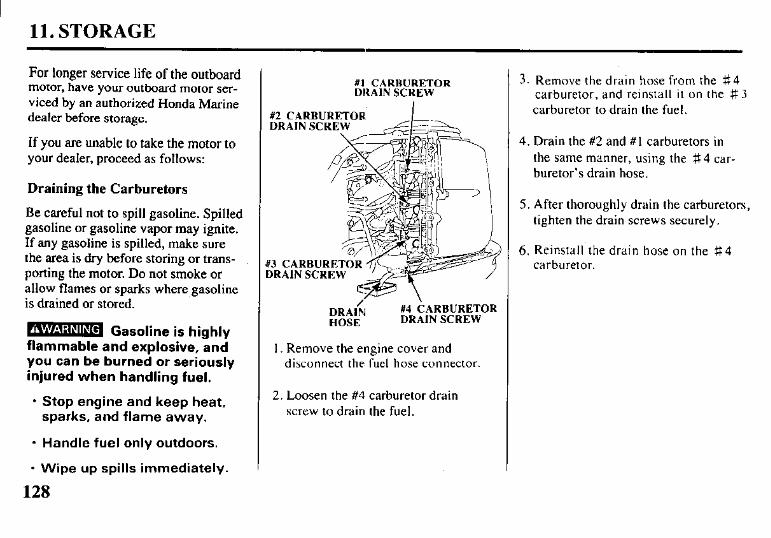
I 11. STORAGE
For longer service life of the outboard motor, have your outboard motor ser- viced by an authorized Honda Marine dealer before storage.
If you are unable to take the motor to your dealer, proceed as follows:
Draining the Carburetors
Be careful not to spill gasoline. Spilled gasoline or gasoline vapor may ignite. If any gasoline is spilled, make sure the area is dry before storing or trans- porting the motor. Do not smoke or allow flames or sparks where gasoline is drained or stored.
m Gasoline is highly flammable and explosive, and you can be burned or seriously injured when handling fuel.
l Stop engine and keep heat, sparks, and flame away.
l Handle fuel only outdoors.
l Wipe up spills immediately.
128
#I CARHURETOR DRAIN SCREW
#2 CARBURETOR DRAIN SCREW
f3 CARBURETOR 3RAIN SCREW
DRA& ~4 CARBURETOR HOSE DRAIN SCREW
1. Remove the engine cover and disconnect the fuel hose connector.
2. Loosen the #4 carburetor drain screw to drain the fuel.
3. Remove the drain hose from the g4 carburetor, and reinstall it on the # 3 carburetor to drain the fuel.
4. Drain the #2 and #I carburetors in the same manner, using the $$. 4 car- buretor’s drain hose.
5. After thoroughly drain the carburetors, tighten the drain screws securely.
6. Reinstall the drain hose on the #4 carburetor.
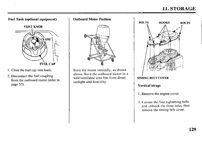
11. STORAGE
Fuel Tank (optional equipment)
VENT KNOB
FUEL CAP
1. Close the fuel cap vent knob.
2. Disconnect the fuel coupling from the outboard motor (refer to page 53).
Outboard Motor Position
Store the motor vertically, as shown above. Store the outboard motor in a well-ventilated area free from direct sunlight and humidity.
BOLTS HOOKS BOLTS
TIhiING BELT COVER
Vertical strage
1. Remove the engine cover.
2. Loosen the four tightening bolts and unhook the three hoks, then remove the timing belt cover.
129
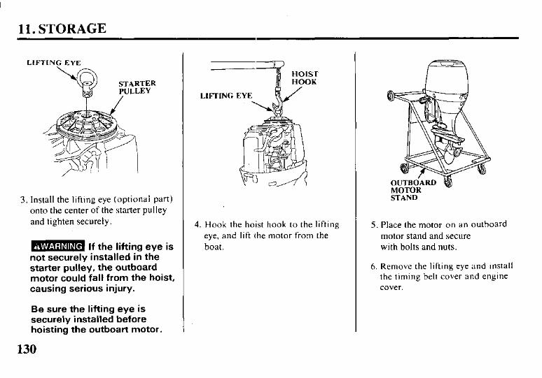
11. STORAGE
LIFI‘ING EYE
3. Install the lifting eye (optional part) onto the center of the starter pulley and tighten securely.
m If the lifting eye is not securely installed in the starter pulley, the outboard motor could fall from the hoist, causing serious injury.
Be sure the lifting eye is securely installed before hoisting the outboart motor.
4. Hook the hoist hook to the lifting eye, and lift the motor from the boat.
STAND
5. Place the motor on an outboard motor stand and secure with bolts and nuts.
6. Remove the lifting eye and install the timing belt cover and engine cover.
130
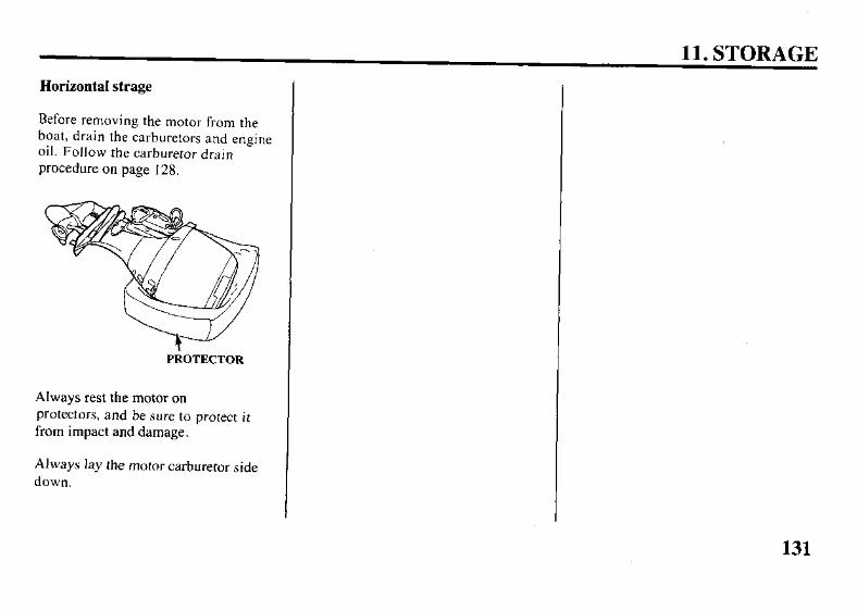
11. STORAGE
Horizontal strage
Before removing the motor from the boat, drain the carburetors and engine oil. Follow the carburetor drain procedure on page 128.
PROTECTOR
Always rest the motor on protectors, and be sure to protect it from impact and damage.
Always lay the motor carburetor side down.
131
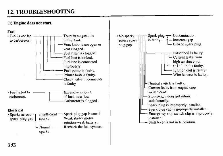
12. TROUBLESHOOTING
(1) Engine does not start.
Fuel l Fuel is not fed -
to carburetor. There is no gasoline in fuel tank. Vent knob is not open or vent clogged. Fuel filter is clogged. Fuel line is kinked. Fuel line is connected improperly. Fuel pump is faulty. Primer bulb is faulty. Check valve in connector is faulty
L
l Fuel is fed to carburetor.
Electrical l Sparks across Insufficient - Spark plug gap is small.
spark plug gap sparks Weak starter motor rotation-weak battery.
Nomal- Recheck the fuel system. sparks
132
l No sparks across spark
PM isap
Contamination Incorrect gap Broken spark plug
Pulser coil is faulty. Current leaks from high tension cord. C.D.I. unit is faulty. Ignition coil is faulty. Wire harness is faulty.
Neutral switch is faulty. Current leaks from engine stop switch cord. Stop switch does not return satisfactorily. Spark plug is improperly installed. Spark plug cap is improperly installed. Emergency stop switch clip is improperly installed. Shift lever is not in N position.
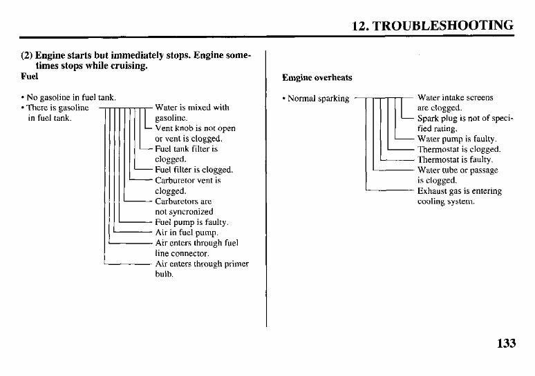
12. TROUBLESHOOTING
(2) Engine starts but immediately stops. Engine some- times stops while cruising.
Fuel
l No gasoline in fuel tank. l Normal sparking l There is gasoline -
in fuel tank. r Water is mixed with gasoline. Vent knob is not open or vent is clogged.
- Fuel tank filter is clogged. Fuel filter is clogged. Carburetor vent is
*
clogged.
Air enters
Carburetors are not syncronized
- Fuel pump is faulty. - Air in fuel pump.
through fuel line connector. Air enters through primer bulb.
I
Emgine overheats
Water intake screens are clogged. Spark plug is not of speci- fied rating. Water pump is faulty. Thermostat is clogged. Thermostat is faulty. Water tube or passage is clogged. Exhaust gas is entering cooling system.
133
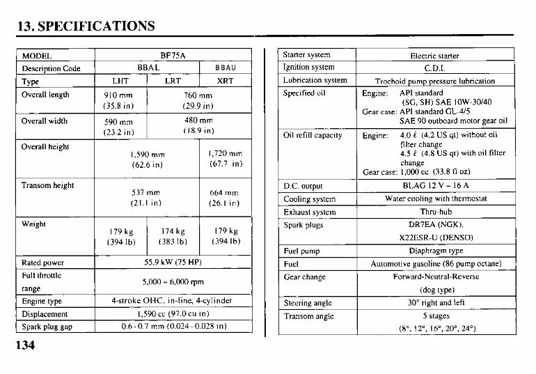
13. SPECIFICATIONS
MODEL
Description Code
Type
Overall length
Overall width
Overall height
Transom height
Weight
Rated power
Full throttle
range
Engine type
Displacement
Spark plug gap
BF75A
BBAL BHAL
LHT LRT XRT
910 mm 760 mm
(35.8 in) (29.9 in)
590 mm 480 mm
(23.2 in) (18.9 in)
I.590 mm 1,720 mm
(62.6 in) (67.7 in)
537 mm 664 mm
(21.1 in) (26.1 in)
179 kg 174 kg 179 kg
(394 lb) (383 lb) (394 lb)
55.9 kW (75 HP)
5,000 - 6,000 rpm
4-stroke OHC, in-line, 4-cylinder
1,590 cc (97.0 cu in)
0.6-0.7 mm (0.024-0.028 in)
Starter system
Ignition system
Lubrication system
Specified oil
Oil refill capacity
D.C. output
Cooling system
Exhaust system
Spark plugs
Fuel pump
Fuel
Gear change
Steering angle
Transom angle
Electric starter
C.D.I.
Trochoid pump pressure lubrication
Engine: API standard (SC, SH) SAE lOW-30/40
Gear case: API standard CL-4/5 SAE 90 outboard motor gear oil
Engine: 4.0 e (4.2 US qt) without oil filter change 4.5 e (4.8 US qt) with oil filter change
Gear case: I.000 CC (33.8 fl ox)
BLAG l2V- l6A
Water cooling with thermostat
Thru-hub
DR7EA (NGK),
X22ESR-U (DENSO)
Diaphragm type
Automotive gasoline (86 pump octane)
Forward-Neutral-Reverse
(dog type)
30” right and left
5 stages
(8”. 12”. 16”. 20’. 24”)
134
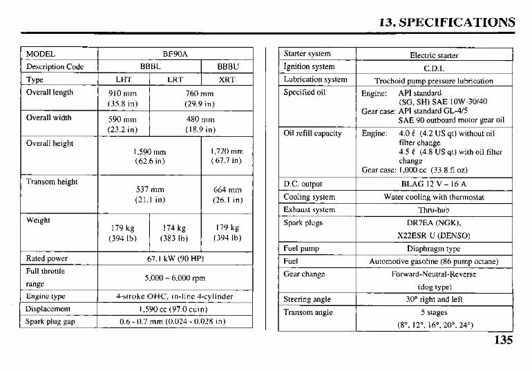
13. SPECIFICATIONS
MODEL
Description Code
‘be
Overall length
Overall width
Overall height
Transom height
Weight
Rated power
Full throttle
range
Engine type
Displacement
Spark plug gap
BF90A
BBBL 1 BBBU
LHT 1 LRT 1 XRT
910 mm 760 mm
(35.8 in) (29.9 in)
590 mm 480 mm
(23.2 in) (18.9 in)
I.590 mm 1,720 mm
(62.6 in) (67.7 in)
537 mm
(21.1 in)
179 kg 174 kg
(394 lb) (383 lb)
664 mm
(26.1 in)
179 kg
(394 lb)
67. I kW (90 HP)
5,000 - 6,000 ‘pm
4-stroke OHC, in-line 4-cylinder
1.590 cc (97.0 cuin)
0.6 - 0.7 mm (0.024 - 0.028 in)
Starter system Electric starter
Ignition system C.D.I.
Lubrication system
Specified oil
Oil refill capacity
Trochoid pump pressure lubrication
Engine: API standard (SC, SH) SAE lOW-30140
Gear case: API standard GL-415 SAE 90 outboard motor gear oil
Engine: 4.0 e (4.2 US qt) without oil filter change 4.5 e (4.8 US qt) with oil filter change
D.C. output
Cooling system
Exhaust system 1
Gear case: 1,000 cc (33.8 fl oz)
BLAG 12V-16A
Water cooling with thermostat
Thru-hub
Spark plugs DR7EA (NGK),
X22ESR-U (DENSO)
Fuel pump Diaphragm type
Fuel
Gear change
Steering angle
Transom angle
Automotive gasoline (86 pump octane)
Forward-Neutral-Reverse
(dog type)
30” right and left
5 stages
(8”, 12”, 16”, 20”, 24”)
135
14. WARRANTY SERVICE
Warranty Service Information
Servicing dealership personnel are trained professionals. They should be able to answer any question your may have. If you encounter a problem that your dealer does not solve to your satisfaction, please discuss it with the dealership’s management. The Service Manager or General Manager can help. Almost all problems are solved in this way.
If you are dissatisfied with the deci- sion made by the dealership’s manage- ment, contact the Honda Marine Customer Relations Office. You can write:
American Honda Motor Co., Inc. Marine Division Customer Relations Office 4475 River Green Parkway Duluth, Georgia 30096-2565 Or telephone: (770) 497-6400
When you write or call, please give us this information:
l Model and serial numbers (see page 3)
l Name of the dealer who sold the outboard motor to you
l Name and address of the dealer who services our outboard motor
l Date of purchase
l Your name, address, and telephone number
l A detailed description of the problem
136
Current customer service contact information: Your owner's manual was written to cover most of the questions you might ask about your Honda. Any questions not answered in the owner's manual can be answered by your Honda dealer. If your dealer doesn't have an immediate answer, they should be able to get it for you.
If you have a difference of opinion with your dealer, please remember that each dealership is independently owned and operated. That's why it's important to work to resolve any differences at the dealership level. If the service personnel are unable to assist you, please discuss your concerns with the dealer management such as the Service Manager or the dealership's owner.
If you need to contact American Honda regarding your experiences with your Honda product or with your dealer, please send your comments to the following address:
American Honda Motor Co., Inc. Marine Division Customer Relations Office 4900 Marconi Drive Alpharetta, GA 30005-8847
Or telephone: (770) 497-6400 M-F, 8:30 am - 7:00 pm EST
When you write or call, please provide the following information:
• Your name, address and telephone number (complete with area code)
• Model and complete serial number
• Date of purchase
• Name and location of the selling dealer
• Name and location of the servicing dealer (if different)
• A detailed description of your concerns
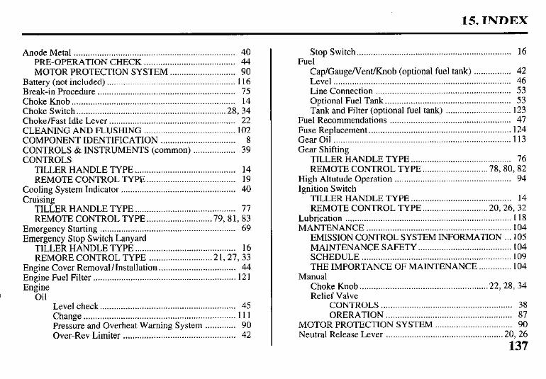
15. INDEX
Anode Metal ..................................................................... 40 PRE-OPERATION CHECK ....................................... 44 MOTOR PROTECTION SYSTEM ............................ 90
Battery (not included) ....................................................... 116 Break-in Procedure ........................................................... 75 Choke Knob.. .................................................................... 14 Choke Switch.. ............................................................. .28, 34 Choke/Fast Idle Lever ...................................................... 22 CLEANING AND FLUSHING ....................................... 102 COMPONENT IDENTIFICATION ................................ 8 CONTROLS & INSTRUMENTS (common) .................. 39 CONTROLS
TILLER HANDLE TYPE ........................................... 14 REMOTE CONTROL TYPE ...................................... 19
Cooling System Indicator ................................................. 40 Cruising
TILLER HANDLE TYPE . . . . . . . . . . . . . . . . . . . . . . . . . . . . . . . . . . . . . . . . . . . 77 REMOTE CONTROL TYPE.. ......................... .79, 8 1, 83
Emergency Starting .......................................................... 69 Emergency Stop Switch Lanyard
TILLER HANDLE TYPE ........................................... 16 REMORE CONTROL TYPE .......................... .2 1, 27, 33
Engine Cover Removal/Installation ................................. 44 Engine Fuel Filter .............................................................. 12 1 Engine
Oil Level check.. ........................................................ 45 Change ................................................................. 111 Pressure and Overheat Warning System ............. 90 Over-Rev Limiter ................................................ 42
Stop Switch .................................................................. 16 Fuel
Cap/Gauge/Vent/Knob (optional fuel tank) ................ 42 Level ............................................................................ 46 Line Connection .......................................................... 53 Optional Fuel Tank ...................................................... 53 Tank and Filter (optional fuel tank) ............................ 123
Fuel Recommendations .................................................... 47 Fuse Replacement ............................................................. 124 Gear Oil ............................................................................ 113 Gear Shifting
TILLER HANDLE TYPE ........................................... 76 REMOTE CONTROL TYPE.. ......................... .78, 80, 82
High Altutude Operation .................................................. 94 Ignition Switch
TILLER HANDLE TYPE ........................................... 14 REMOTE CONTROL TYPE.. ......................... .20, 26, 32
Lubrication ....................................................................... 118 MANTENANCE .............................................................. 104
EMISSION CONTROL SYSTEM INFORMATION .. .105 MAINTENANCE SAFETY.. ...................................... 104 SCHEDULE ................................................................ I09 THE IMPORTANCE OF MAINTENANCE .............. 104
Manual Choke Knob.. .................................................... .22, 28, 34 Relief Valve
CONTROLS ........................................................ 38 ORERATION ...................................................... 87
MOTOR PROTECTION SYSTEM ................................. 90 Neutral Release Lever ................................................. .20, 26
137
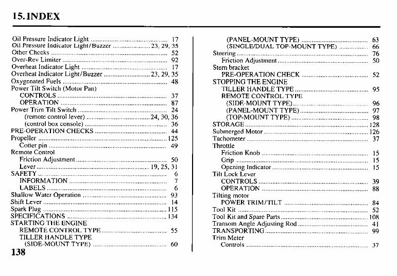
15. INDEX
Oil Pressure Indicator Light ............................................. I7 Oil Pressure Indicator Light/Buzzer ..................... .23, 29, 35 Other Checks .................................................................... 52 Over-Rev Limiter ............................................................. 92 Overheat Indicator Light .................................................. I7 Overheat Indicator Light/Buzzer .......................... .23, 29, 35 Oxygenated Fuels ............................................................. 48 Power Tilt Switch (Motor Pan)
CONTROLS ................................................................ 37 OPERATION .............................................................. 87
Power Trim Tilt Switch .................................................... 24 (remote control lever) .................................... .24, 30, 36 (control box console) ................................................ 36
PRE-OPERATION CHECKS .......................................... 44 Propeller .................................................................. . ........ I25
Cotter pin .................................................................... 49 Remote Control
Friction Adjustment.. ................................................... 50 Lever.. ................................................................ 19, 25, 3 I
SAFETY ........................................................................... 6 INFORMATION ......................................................... 7 LABELS ...................................................................... 6
Shallow Water Operation ................................................. 93 Shift Lever.. ...................................................................... I4 Spark Plug ........................................................................ I 15 SPECIFICATIONS .......................................................... I34 STARTING THE ENGINE
REMOTE CONTROL TYPE.. .................................... 55 TILLER HANDLE TYPE
(SIDE-MOUNT TYPE) ........................................... 60
138
(PANEL-MOUNT TYPE) ....................................... 63 (SINGLE/DUAL TOP-MOUNT TYPE) ................. 66
Steering ............................................................................. 76 Friction Adjustment.. ................................................... 50
Stem bracket PRE-OPERATION CHECK ....................................... 52
STOPPING THE ENGINE TILLER HANDLE TYPE ........................................... 95 REMOTE CONTROL TYPE
(SIDE-MOUNT TYPE). ........................................... 96 (PANEL-MOUNT TYPE). ....................................... 97 (TOP-MOUNT TYPE) ............................................. 98
STORAGE.. ...................................................................... I28 Submerged Motor ............................................................. 126 Tachometer ....................................................................... 37 Throttle
Friction Knob .............................................................. I5 Grip ............................................................................. I5 Opening Indicator.. ...................................................... I5
Tilt Lock Lever CONTROLS ................................................................ 39 OPERATION .............................................................. 88
Tilting motor POWER TRIM/TILT ................................................. 84
Tool Kit ............................................................................ 52 Tool Kit and Spare Parts.. ................................................. 108 Transom Angle Adjusting Rod ......................................... 4 I TRANSPORTING.. .......................................................... 99 Trim Meter
Controls ....................................................................... 37
15. INDEX
Operation ..................................................................... 86 Trim Tab
Controls ....................................................................... 39 Adjustment .................................................................. 89
TROUBLESHOOTING ................................................... 132 Troubleshooting, Startcing Problems ............................... 74 WARRANTY SERVICE ................................................. 136 Water Intakes .................................................................... 41 WIRING DIAGRAM ....................................................... 14 1
139

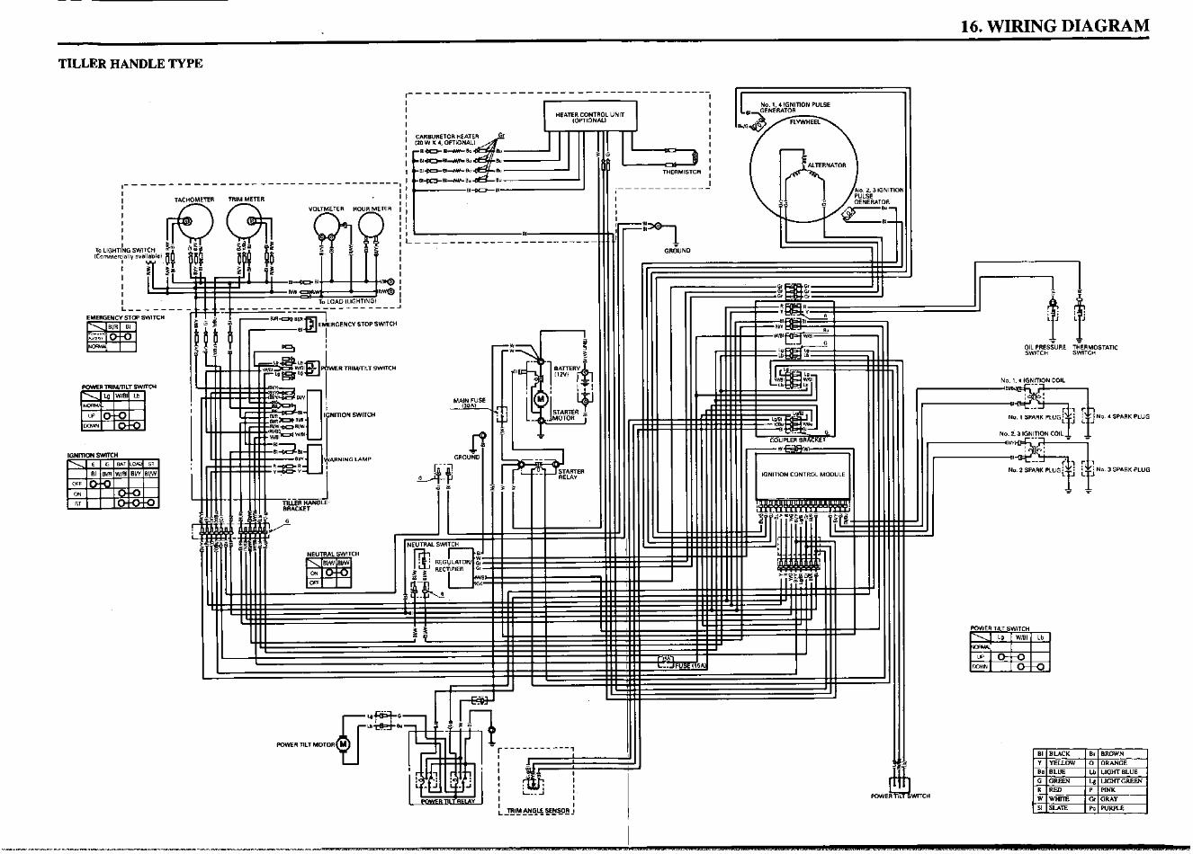
16. WIRING DIAGRAM
TILLER HANDLE TYPE
NO. 1.4 IGNlTlDN PULSE
I- - ---- ------ ---- - ----- -- .-- _ --------
I TACHOMETER TRIM METER
I
I I I I
To LlGHT/NG SW ICammery” a”
I
I
I I I
1 G&ND
EMERGENCY STOP SWITCH
,GN,“ON SWW34
POWER TRlWTlLT SWITCH
. SPARK PLUG
3 SPARK PLUG
IGNITION SWITCH
POWER TILT SWITCH
47
‘MOTOR M POWER TM
I TRIM ANGLE SENSOR ! ___-_-------
I WITCH
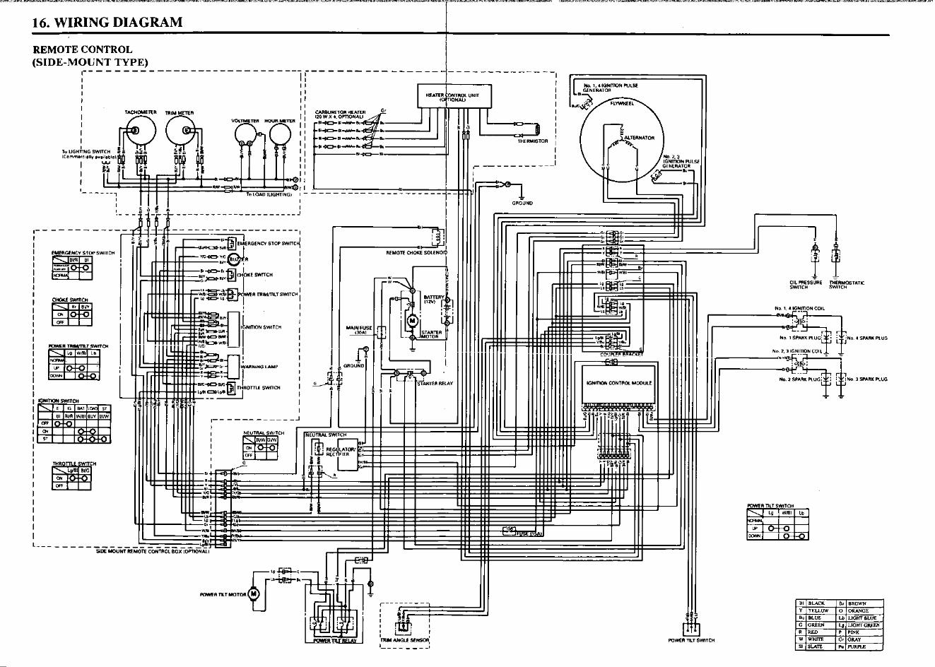
r--- ---- , ;uosN3s3l,m;
fj$i 1
I, - - - - - - --J
h
I ____ --------------- K-kbkc
,----- ------_---------- I J-J-l& I rti; !
II I I
(2IdA.LLNflObU-H<IIS~ 10XLN03 KLOMIBI
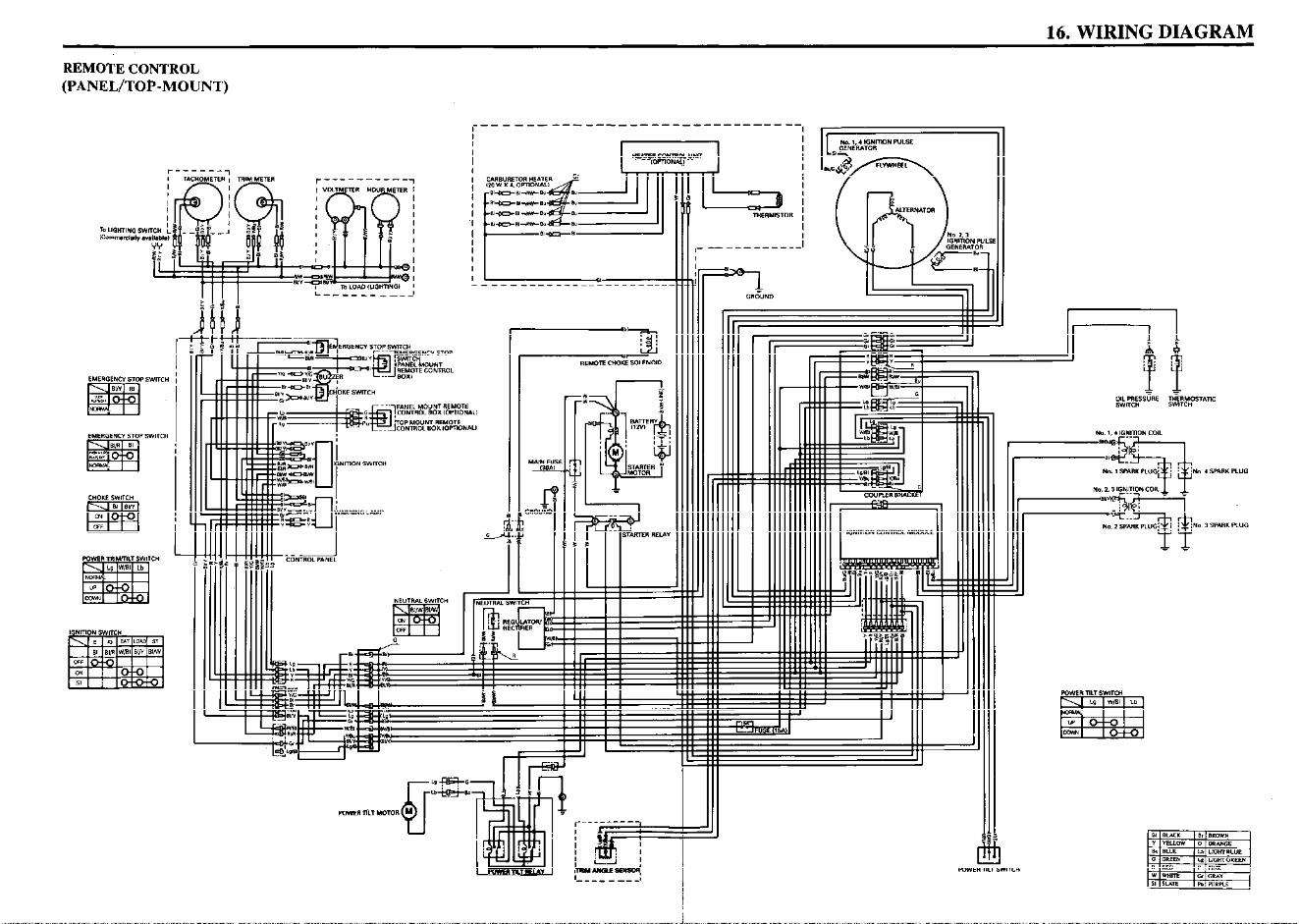
16. WIRING DIAGRAM
REMOTE CONTROL
(PANEL/TO&MOUNT)
r I
I
l-NERMlSTOR I I
I
IGNITION WLSE
EMERGENCY STOP SWITCH
EMERGENCY STOP SWITCH
IGNITION SWITCH
ARNING LAMP
IGNITION SWTC”
‘I
1 POWER


© HONDA MOTOR CO., LTD. 199531ZW060200X31-ZW0-6020
200.2002.05PRINTED IN U.S.A.
BF75A/90AOwner’sManual
EM


![SelectionInformation MiniatureCircuitBreakers … MiniatureCircuitBreakers schneider-electric.us Class500,600 ... 90A — QO290VH[9] — QO390VH[9]](https://static.fdocuments.in/doc/165x107/5ae8df1b7f8b9ab24d8b501c/selectioninformation-miniaturecircuitbreakers-miniaturecircuitbreakers-schneider-electricus.jpg)