Running cables - Selden
12
595-557-E 2016-01-18 Running cables 1 TOP LIGHT 3 ANCHORLIGHT 4 WINDEX 5 FLOOD LIGHT 6 AERIAL 7 WINDINSTRUMENT 1 1 NAIGATION LIGHT
Transcript of Running cables - Selden

1
595-557-E2016-01-18
Running cables
1 TOP LIGHT
3 ANCHORLIGHT
4 WINDEX
5 FLOOD LIGHT
6 AERIAL
7 WINDINSTRUMENT
�
1
1
� NA�IGATION LIGHT

2
Identify the section type of your mast by using the tables below. See also next page. It is quite easy to check the design of the after section by removing the headbox. (See page2).
Retro-fitting cables
(See next page for ”D”,
”P” and furling sections.
- 10° plough-shaped after face- Separate conduits
- 10° plough-shaped after face- Separate conduits - Track for plastic conduits
- 10° plough-shaped after face- Track for plastic conduits- Double marking lines
- Rounded after face. (Excluding section 122/85)
A/B Available cable space 1) Available cable space 1) Available cable space 1) Available cable space 1)
122/85 --
No conduit 2) 2 (13x15)130/93 2 (15x15) mm -
-
138/95 2 (15x15) No conduit 2)
155/104 2 (15x15)2 ▭ (15x16)
+
15x50
(plastic conduit) 4)
-170/155 2 (15x18)
2 ▭ (9x12) 2) 6)
177/124 2 ▭ (15x20)189/132 2 ▭ (15x16) 6)
206/139 2 ▭ (15x16) 6)
224/150 2 ▭ (15x16) 6)
237/162 2 ▭ (15x17) 6)
274/185 - - 2 ▭ (9x12) 2) 6)
321/171- -
See sep. instruction 595-691-... supplied upon
request. -
365/195
126/85
- - -
2 ▭ (10x12)147/95 2 ▭ (10x12)
162/104 2 (15x15)178/115 2 (15x18)216/139 2 (15x20)239/162 2 (17x25)
1. “2 (cxd) mm” = two triangular spaces. c d “2 ▭ (cxd) mm” = two rectangular spaces. c d
2. 2 off maximum. Ø 9 mm cables can be glued to the sail track.
3. ALT: cable tubing 512-118-01 Ø 35x32 (L=5000)
4. Plastic conduit: 535-608-01 (L=6000 mm)
5. Plastic conduit: 535-643-01 (L=6000 mm)
6. Also 2(l)x plastic conduit 535-607-01 16x52 (L=6000)
10° 10° 10°
3)
▭
d
cd
c
INSTRUCTION 1A INSTRUCTION 1B INSTRUCTION 2 INSTRUCTION 3
”E”sections
B
A

3
- 10° plough-shaped after face- Separate conduits
- 10° plough-shaped after face- Separate conduits - Track for plastic conduits
A/B Available cable space 1) Available cable space 1)
109/88 2 Ø 10
-121/92 2 ▭ (15x10)129/100 2 ▭ (15x10)137/113 2 ▭ (15x13)146/112 2 ▭ (15x13)
160/132 2 ▭ (17x14) 2 ▭ (17x14) +15x50 (plastic conduit) 4)
INSTRUCTION 1A INSTRUCTION 1B
Dprofiler
- Pear-shaped cross section
A/B Available cable space 1)
75/53 2 (8x12)90/65 2 (8x12)
100/73 2 (10x15)111/81 2 (10x15)123/90 2 (8x12)137/100 2 (10x18)152/111 2 (10x15)169/123 2 (15x15)188/137 2 (15x15)
INSTRUCTION 3
Pprofiler
A/B Available cable space 1) Available cable space 1)
214/122 - 15x50 (plastic conduit) 5)
232/126 2 ▭ 28x28 -260/136 2 ▭ 28x32 -290/150 2 ▭ 28x35 -324/169 See sep. instruction 595-691-...
supplied upon request. 370/192
INSTRUCTION 4 INSTRUCTION 4
FURLING
10°
B
A
10°
B
A
APPROXIMATE OUTER DIAMETERS OF CABLES Diameter(mm)
Navigation & Deck Lights Ø 7 - Ø 8,5Anchor Light Ø 6,5VHF Ø 5 - Ø 10Radar Ø 12,5 - Ø 2AP Navigator (Decca, Loran C) Ø 6 (Ø 8)Satellit Navigator Ø 6
1 TOP LIGHT
3 ANCHORLIGHT
4 WINDEX
5 FLOOD LIGHT
6 AERIAL
7 WINDINSTRUMENT
�
1
1
� NA�IGATION LIGHT
Cable identificationSelden Mast AB have a cable identi-fication system to facilitate connec-ting when maststepping.

4
Excepting at the headbox, at the partners, and at the heel, cable conduits are open along the mast track face. Remove the headbox by taking off the nuts on the top of the box, and lift the box upwards. Drill hole(s) for the cable(s) in the centre of the mast-wall face of the cable conduit approximately 50 mm (2’) below the cut-out for the headbox. Take care not to damage any cables already in situ. Select the side opposite the main halyard if possible.
Drill the hole at an angle to minimize the risk of chafe, and burr it carefully. Same turns, of adhesive tape around the cable contribute towards a fairer cable passage. (See fig. l.A.2). Standard plastic cable grommets are available for same cable sizes. Any holes needed at spreader level or elsewhere for deck lights, etc. are executed in the same manner. Mast heel fittings are already provided with cable exit holes.
FITTINGINSTRUCTION 1A (”D” och ”E”-sections with separate conduits)
1 Equipment required• Cable • Closed cell foam plastic pads (approx. 20x20x20 mm) • Adjustable spanner • Drill • Drill bit. (appr. 4 mm larger diameter than that of cable) • Bent plate strip, 100x15xl,5 mm. • Thin line, O,5 m. in length, Ø 3-4 mm.• Silicone compound (keel stepped masts only)
2 Preparation
With the help of a length of messenger line draw the cable upwards from the heel (see fig. l.A.3). Alternatively, make an eye at the cable end, and pull the cable along the conduit with the aid of a small screwdriver. Feed the cable through the pre-drilled exit hole at the mast-head.
3 Fitting procedure
Cut-out for headbox
50 mm (2”)
Edges of hole carefully burred.
Messenger line
Cable
Heel fitting
Sail track
Conduit
Fig. 1.A.1
Fig. 1.A.2
Fig. 1.A.3 Fig. 1.A.4

5
A messenger and a long hook will facilitate passing the goose-neck fitting and track gate. Track gates that are screwed in place are easily removed. The aforementioned eye on the cable end facilitates threading the cable th-rough the hole at the mast-head. To avoid the weight of the cable from being suspended from the point of mast head exit, and to prevent the cable from slamming inside the conduit, the cable must be wedged in place. This is best done by forcing pads of closed cell plastic foam at regular intervals along the conduit lenght. Their size is dependant upon the space occupied by the cable(s) in the conduit. Try first with 20x20x20 mm pads, fitting them as shown in figs. l.A.5A to C. It can be a little tricky at first, but one soon gets the knack of it. A pad every 60 cm (2’) gives satisfactory support. The advantage of pads over gluing is that the pads are easily removed if one wants to remove the cable at a later date. (See the last paragraph on this page).
On keel stepped masts the sailtrack and conduits are sealed with silicone rubber on a level with the upper edge of the mast coat. An exception are those masts that have been left unsealed on customer request, and these are clearly labelled ”OPEN CONDUITS”. (See instruction 595-548-E, not attached). This packing must be remo-ved to give free passage for the cable * and be replaced after the cable has been installed. There are holes where the sealant can be injected to re-seal the conduits just above or just below the top edge of the coat.
If existing cables are glued, no further steps need be taken. If they are held in place with pads the pads must first be removed before fitting the new cable. Remove the headbox (fig. l.A.2). Insert a hook-shaped plate strip (fig. l.A.5b) below one pad at a time, push the pad to the top end of the mast, and remove it. The track gate can also be removed, and pads pushed there for removal. These pads can later be re-used for holding both the old and the new cables.
*) This is a time-consuming task, so contact Seldén Mast for advice. The method shown opposite can be used for thin cables (appr. 6,5 mm Ø 1,4” maximum). It is easier to remove sealing compound from the sail track than from a conduit.
Keel stepped masts
PadCable
Hook-shaped plate strip. Jaw length appr. 10 mm.
Cable
Sealing
Conduit
Cable in conduit
WIEWED FROM AFT:
Sail track
Cable in conduit
Cable in sail track
SECTION
Fig. 1.A.5a Fig. 1.A.5b Fig. 1.A.5c

6
a. Fitting cables in conduit sections To be carried out acc. to Instruction 1A.
b. Fitting cables in additional plastic conduits
FITTINGSTRUCTION 1B (”D” and ”E”-sections with separate conduits and track for plastic conduits)
1 Equipment required
• Cable • Adjustable spanner • Drill • Drill bit (appr. 4 mm larger diameter than that of cable) • Silicone sealant - for keel stepped masts only • (Messenger line, Ø 3-4 mm, length = mast length)
The cables are fed through the conduits with help of the existing messenger line(s). If messenger lines are missing the easiest way to fit them is with the aid of a conduit feeder (a long steel strip used by electricians).
Alternatively, the messenger can be fitted with the mast stepped. Try to stay the boat to minimize rolling. Attach a small weight such as a nut to the end of the new messenger and lower it from the mast head to the heel, where it can be taken out (fig. 1.B.1).
In keel stepped masts the conduit passes through the internal seal. (Fig. 1.B.2). A new messenger should accompany the cable to facilitate future installations.
2 Fitting procedure
Plastic conduit
Drainage hole
Seal
Mast coat upper edge
Plastic conduit
Messenger
Messenger carrier weight taken out through centre of heel fitting,Fig. 1.B.1 Fig. 1.B.2
Deck stepped mast Keel stepped mast
7
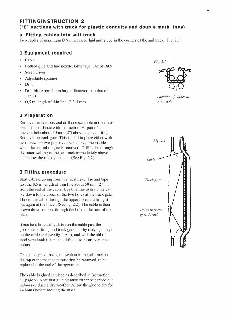
a. Fitting cables into sail trackTwo cables of maximum Ø 9 mm can be laid and glued in the corners of the sail track. (Fig. 2.1).
FITTINGINSTRUCTION 2 (”E” sections with track for plastic conduits and double mark lines)
1 Equipment required
Remove the headbox and drill one exit hole in the mast-head in accordance with Instruction lA, point 2, and one exit hole about 50 mm (2”) above the heel fitting. Remove the track gate. This is held in place either with two screws or two pop-rivets which become visible when the central tongue is removed. Drill holes through the inner walling of the sail track immediately above and below the track gate ends. (See Fig. 2.2).
2 Preparation
• Cable• Bottled glue and fine nozzle. Glue type Cascol 1809 • Screwdriver • Adjustable spanner • Drill• Drill bit (Appr. 4 mm larger diameter than that of
cable) • O,5 m length of thin line, Ø 3-4 mm
Start cable drawing from the mast head. Tie and tape fast the 0,5 m length of thin line about 50 mm (2”) in from the end of the cable. Use this line to draw the ca-ble down to the upper of the two holes at the track gate. Thread the cable through the upper hole, and bring it out again at the lower. (See fig. 2.2). The cable is then drawn down and out through the hole at the heel of the mast.
It can be a little difficult to run the cable past the goose-neck fitting and track gate, but by making an eye on the cable end (see fig. l.A.4), and with the aid of a steel wire hook it is not so difficult to clear even those points.
On keel stepped masts, the sealant in the sail track at the top ot the mast coat must tirst be removed, to be replaced at the end of the operation.
The cable is glued in place as described in Instruction 3, (page 9). Note that glueing must either be carried out indoors or during dry weather. Allow the glue to dry for 24 hours before moving the mast.
3 Fitting procedure
l.ocation of cables at track gate.
Cable
Track gate
Holes in bottom of sail track
Fig. 2.2
Fig. 2.1

8
b. Fitting cables in separate plastic conduitsFollow Instruction 1B.b, ”Cables in separate plastic conduits”. There are two executions for through-deck fitting on keel stepped masts.
Alt. 1 Plastic conduits (aft and/or forward) pass uninter-rupted through seal at deck level.
Alt. 2 Plastic conduit ends above deck level seal. Cable(s) pass through conduit tube in centre of mast. (Older types).
Plastic conduit
Drainage hole
SealMast coat upper edge
Deck level
Sealant injection hole
Messenger line
Conduit tube
No plastic conduit below sealFig. 2.4
Fig. 2.3
The type of execution can be checked by inspection through the two drain holes on the sides of the mast im-mediately above the mast coat.
Alt. 1 The after conduit may be sealed. If it is to be used then the sealant must be removed through the two injection holes which are sited either just above or just below the upper edge of the mast coat. Unfort- unately this can be very difficult. Contact Seldén Mast for advice. (The mast coat may have to be temporarily pulled downwards on the mast).
Alt. 2 The cables are drawn through the conduits by the messenger line. A new messenger line should be draw through parallel and at the same time as cables are drawn through in case one later wants to draw more cables. If no messenger line is present, one should be fitted as described in instruction 1B point b2.
It can be awkward getting a messenger line through the conduit tube. A steel wire hook pushed through a drainage hole can be of valuable assistance in getting the messenger line to the conduit tube from the main conduit.
Some mast heels have cable exit holes in their after part as shown in fig. 1.A.3.

9
FITTINGINSTRUCTION 3 (E-sections with rounded after face)
1 Equipment required
Remove the headbox and drill an exit hole at the mast head following Instruction 1A, point 2. Be careful of existing cables. Exit holes are already cast into the mast heel. (See instruction lA, fig. l.A.3).
2 Preparation
• Cable • Bottled glue and fine nozzle; Glue type Cascol 1809 • Adjustable spanner • Drill• Drill bit (Appr. 4 mm larger diameter than that of table) • 0,5 m length of thin line. Ø 3-4mm• Silieone sealant - for keel stepped masts only
Cables are drawn upwards fram heel according to Instruction lA, fig. l.A.3. Read Instruction lA on how to run cable past the deck sealing on keel stepped masts.
Lay the mast horizontally on two supports and angle it slightly as shown in fig. 3.1.
Tension the cable weil and apply the glue to the cable along the whole length of the mast.
3 Fitting
Glueing must be undertaken indoors or in dry weather: The glue must be left to set for 24 hours before moving the mast.
If several cables are to be fitted they should be glued close to each other and one at a time, with a couple of hours’ time gap to allow the glue from the first application to gain same initial strength.
The deck level seal must be replaced on keel stepped masts. See page 5.
Donotoverdosetheglue.Cascol1809isafoamingglueandwillfillthemasttrackif overdosing.Makesuretoglueonadrysurface. Makeatestoutsidethemasttrackorinapartofthemasttrackwherenosailishoisted.
Fig. 3.1

10
FITTINGINSTRUCTION 4 (Furling sections)
1 Equipment required
Cables are fed through the conduits using the existing messenger line(s). On keel steppped masts the conduits pass through the deck level seal. A new messenger line is drawn through together with the cable, to remain in situ for possible future use.
There are exit holes already in place at the mast head and heel.
Previously drawn cable can hinder the drawing of new cable. In which ca se the old cable must first be removed - not forgetting to tie a new messenger line to it first before withdrawing it. There are exit holes at, or close to, the mast head and heel.
A cable exit can easily be arranged on furling sections 232/126 and upwards. The exit hole must be drilled with the greatest care so as not to damage existing cables. Lay the mast with its forward face uppermost so that existing cables lie in the after corner of the conduit. Drill the exit hole in the opposite corner. Drill the hole at a slight angle to minimise the risk of cable wear. A couple of tums of tape around the new cable will also help to give the cable a fairer exit run.
Cable that is to exit between mast head and heel on furling sections 190/94-214/122, 235/116 have to lie free within the forward chamber: Stretch the cable hard to avoid slamming.
2 Fitting
• Cable • Messenger line at least as long as the mast, and Ø 3-4 mm • Drill • Drill bit (if the cable is to exit between mast head and foot)
Conduit Conduits
SECTION RA 190/94-214/122, 235/116 SECTION RB/RC 232/126, 260/136, 290/150

11
Extra equipment
Windex base
Windex base for 15° headbox angle. Part No. 508-549-01 Windex extension base. Part No. 508-521-01
Antenna or Wind instrumentation base for 15º headbox angle
Antenna and Wind Instrumentation Base with place for several antennae and instruments
Windex light
Anchor light
Masthead Combination Light
Medium size (100 x 40 mm) Part no. 508-563-01 Larger size (180 x 65 mm) Part no. 508-541-01
Medium size, 550 x 80 mm Part No. 508-556-01 + 508-508-01 Ditto, with large base Part No. 508-556-01 + 508-541-01 Large plate, 800 x 80 mm Part No. 508-559 -01
(With or without anchor light). With anchor light, Part No. 526-021-02 Without anchor light, Part No. 526-020-02Part no. 526-163-01
Part no. 526-153-01

12
Seld
én a
nd F
urle
x ar
e re
gist
ered
trad
emar
ks o
f Sel
dén
Mas
t AB
Seldén Mast AB, Sweden Tel +46 (0)31 69 69 00 Fax +46 (0)31 29 71 37 e-mail [email protected]
Seldén Mast Limited, UK Tel +44 (0) 1329 504000 Fax +44 (0) 1329 504049 e-mail [email protected]
Seldén Mast Inc., USA Tel +1 843-760-6278 Fax +1 843-760-1220 e-mail [email protected]
Seldén Mast A/S, DK Tel +45 39 18 44 00 Fax +45 39 27 17 00 e-mail [email protected]
Seldén Mid Europe B.V., NLTel +31 (0) 111-698 120 Fax +31 (0) 111-698 130 e-mail [email protected]
Seldén Mast SAS, FRTel +33 (0) 251 362 110 Fax +33 (0) 251 362 185 e-mail [email protected]
Seldén Mast Asia Ltd, Hong KongTel +852 3572 0613 Fax +852 3572 0623 e-mail [email protected]
www.seldenmast.com
Dealer:
DINGHIESKEELBOATSYACHTS
The Seldén Group is the world’s leading manu-
facturer of mast and rigging systems in carbon and
aluminium for dinghies, keelboats and yachts.
Our well known brands are Seldén and Furlex.
The worldwide success of Furlex has enabled us to
build a network of over 750 authorised dealers
covering the world’s marine markets. So wherever
you sail, you can be sure of fast access to our
service, spare parts and know-how.
SELDÉN and FURLEX are registered trademarks of Seldén Mast AB