ÄKTAdesignsydney.edu.au/medicine/bosch/facilities/molecular-biology...controlled from a PC running...
44
ÄKTAdesign Monitor pH/C-900 User Manual GE Healthcare
Transcript of ÄKTAdesignsydney.edu.au/medicine/bosch/facilities/molecular-biology...controlled from a PC running...
ÄKTAdesignMonitor pH/C-900
User Manual
GE Healthcare

Monitor pH/C-900 User Manual 18-1120-06 Edition AF 3
Important user information
All users must read this entire manual to fully understand the safe use of ÄKTAdesign™ Monitor pH/C-900.
IMPORTANT! ÄKTAdesign Monitor pH/C-900 is intended for laboratory use only, not for clinical or in vitro use, or for diagnostic purposes.
WARNING!
The Warning sign highlights an instruction that must be strictly followed in order to avoid personal injury. Be sure not to proceed until the instructions are clearly understood and all stated conditions are met.
CAUTION!
The Caution sign is used to call attention to instructions or conditions that must be followed to avoid damage to the product or other equipment. Be sure not to proceed until the instructions are clearly understood and all stated conditions are met.
Note!
The Note sign is used to indicate information important for trouble-free and optimal use of the product.
Recycling
This symbol indicates that the waste of electrical and electronic equipment must not be disposed as unsorted municipal waste and must be collected separately. Please contact an authorized representative of the manufacturer for information concerning the decommissioning of equipment.
WARNING!
This is a class A product. In a domestic environment, it may cause radio interference, in which case the user may be required to take appropriate measures.
WARNING!
All repairs should be done by personnel authorized by GE Healthcare. Do not open any covers or replace any parts unless specifically stated in the instructions.
CE Certification
This product complies with the European directives listed below, by fulfilling corresponding standards.
A copy of the Declaration of Conformity is available on request.
• 73/23/EEC, Low Voltage Directive
• 89/336/EEC, EMC Directive
The CE logo and corresponding declaration of conformity, is valid for the instrument when it is:
• used as a stand-alone unit, or
• connected to other CE-marked GE Healthcare instruments, or
• connected to other products recommended or described in this manual, and
• used in the same state as it was delivered from GE Healthcare except for alterations described in this manual.
Note: The Declaration of conformity is valid only for systems that are marked with the CE logo::
Contents
Contents
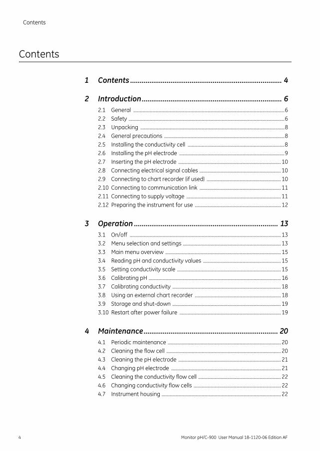
1 Contents ............................................................................... 4
2 Introduction......................................................................... 62.1 General ................................................................................................................................62.2 Safety ....................................................................................................................................62.3 Unpacking ..........................................................................................................................82.4 General precautions ......................................................................................................82.5 Installing the conductivity cell ..................................................................................82.6 Installing the pH electrode .........................................................................................92.7 Inserting the pH electrode ....................................................................................... 102.8 Connecting electrical signal cables ..................................................................... 102.9 Connecting to chart recorder (if used) ............................................................... 102.10 Connecting to communication link ..................................................................... 112.11 Connecting to supply voltage ................................................................................ 112.12 Preparing the instrument for use ......................................................................... 12
3 Operation ........................................................................... 133.1 On/off ................................................................................................................................ 133.2 Menu selection and settings ................................................................................... 133.3 Main menu overview .................................................................................................. 153.4 Reading pH and conductivity values .................................................................. 153.5 Setting conductivity scale ........................................................................................ 153.6 Calibrating pH ................................................................................................................ 163.7 Calibrating conductivity ............................................................................................ 183.8 Using an external chart recorder ......................................................................... 183.9 Storage and shut-down ............................................................................................ 193.10 Restart after power failure ...................................................................................... 19
4 Maintenance...................................................................... 204.1 Periodic maintenance ................................................................................................ 204.2 Cleaning the flow cell ................................................................................................. 204.3 Cleaning the pH electrode ....................................................................................... 214.4 Changing pH electrode ............................................................................................. 214.5 Cleaning the conductivity flow cell ...................................................................... 224.6 Changing conductivity flow cells .......................................................................... 224.7 Instrument housing ..................................................................................................... 22
4 Monitor pH/C-900 User Manual 18-1120-06 Edition AF
Contents
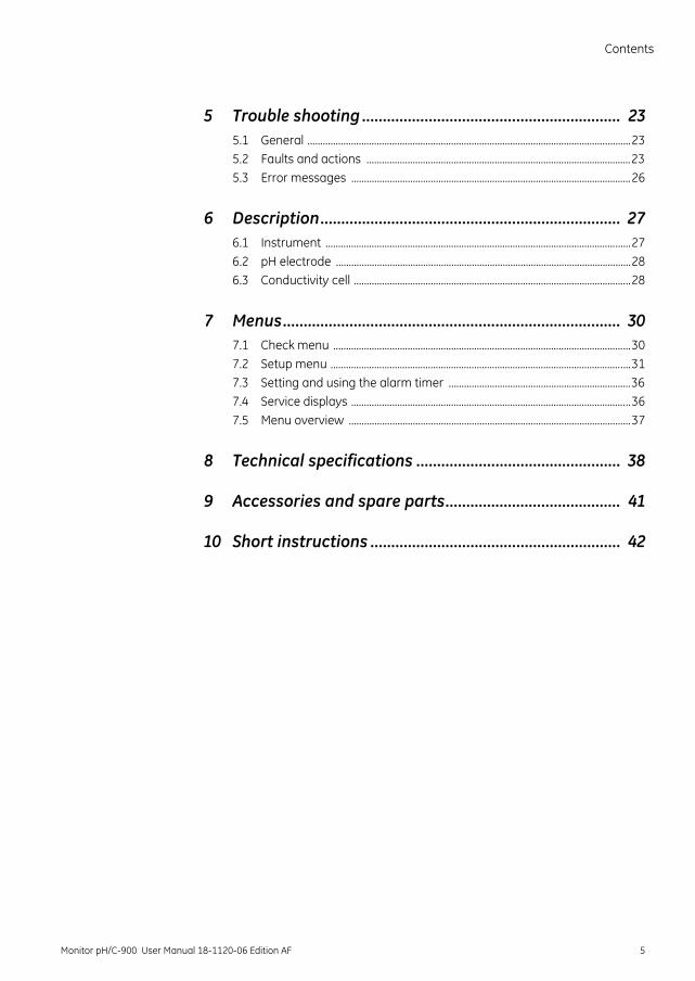
5 Trouble shooting .............................................................. 235.1 General ..............................................................................................................................235.2 Faults and actions .......................................................................................................235.3 Error messages .............................................................................................................26
6 Description........................................................................ 276.1 Instrument .......................................................................................................................276.2 pH electrode ...................................................................................................................286.3 Conductivity cell ............................................................................................................28
7 Menus................................................................................. 307.1 Check menu ....................................................................................................................307.2 Setup menu .....................................................................................................................317.3 Setting and using the alarm timer .......................................................................367.4 Service displays .............................................................................................................367.5 Menu overview ..............................................................................................................37
8 Technical specifications ................................................. 38
9 Accessories and spare parts.......................................... 41
10 Short instructions ............................................................ 42
Monitor pH/C-900 User Manual 18-1120-06 Edition AF 5
1 Introduction
1 Introduction
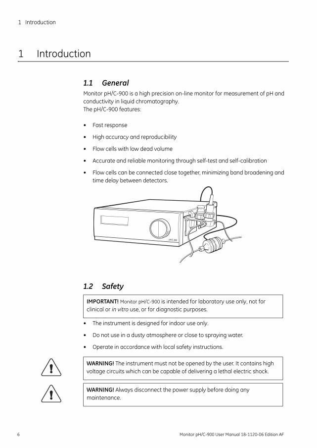
1.1 GeneralMonitor pH/C-900 is a high precision on-line monitor for measurement of pH and conductivity in liquid chromatography. The pH/C-900 features:
• Fast response
• High accuracy and reproducibility
• Flow cells with low dead volume
• Accurate and reliable monitoring through self-test and self-calibration
• Flow cells can be connected close together, minimizing band broadening and time delay between detectors.
1.2 Safety
• The instrument is designed for indoor use only.
• Do not use in a dusty atmosphere or close to spraying water.
• Operate in accordance with local safety instructions.
pH/C-900
IMPORTANT! Monitor pH/C-900 is intended for laboratory use only, not for clinical or in vitro use, or for diagnostic purposes.
WARNING! The instrument must not be opened by the user. It contains high voltage circuits which can be capable of delivering a lethal electric shock.
WARNING! Always disconnect the power supply before doing any maintenance.
6 Monitor pH/C-900 User Manual 18-1120-06 Edition AF
Introduction 1
WARNING! The instrument must be connected to a grounded mains socket.
WARNING! When using hazardous chemicals, take all suitable protective measures, such as wearing protective glasses and gloves resistant to the chemicals used. Follow local regulations and instructions for safe operation and maintenance of the system.
WARNING! Make sure that the pressure from the pump never exceeds the maximum cell pressure to avoid the risk of explosion. See specifications for maximum pressure tolerance.
WARNING! The system should be installed on a stable laboratory bench providing a suitable working area.
Monitor pH/C-900 User Manual 18-1120-06 Edition AF 7

2 Installation
2 Installation
2.1 Unpacking
Unpack the instrument and check the items against the supplied packing list. Inspect the items for obvious damage which may have occurred during transpor-tation.
It is recommended that all packing materials should be retained if onward trans-port of the instrument is expected.
2.2 General precautions
The instrument should be located in a place of low temperature variations, away from heat sources, draughts and direct sunlight.
The instrument shall be operated within its normal ambient temperature range +4 to 40 °C.
The instrument should be installed on a stable laboratory bench or in ÄKTAexplorer™ or ÄKTApurifier™. To ensure correct ventilation a free space of 0.1 m is required behind and in front of the instrument. Do not use any soft mate-rial under the instrument, to ensure that the ventilation inlet in the front is not blocked.
2.3 Installing the conductivity cell1 Place the conductivity cell in a suitable place, for example on the shelf of the
Monitor UV-900 using the clip provided with the UV monitor. The cell can be placed up to 1.5 m from the monitor housing.
CAUTION! The following information should be read carefully to ensure that the instrument is installed correctly
WARNING! Do not block the rear panel of the system. The mains power switch must always be easy to access.
WARNING! Do not block the rear panel of the system. The mains power switch must always be easy to access.
CAUTION! The mains power to pH/C-900 must be switched OFF before connecting the instrument to any cells or external equipment.
8 Monitor pH/C-900 User Manual 18-1120-06 Edition AF
Installation 2
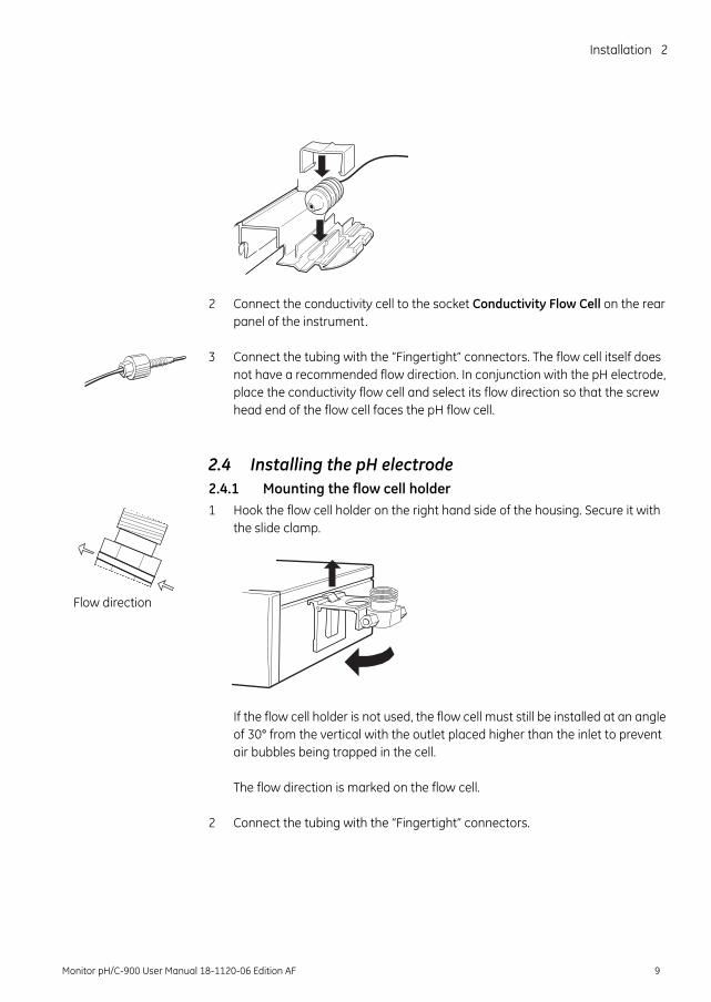
2 Connect the conductivity cell to the socket Conductivity Flow Cell on the rear panel of the instrument.
3 Connect the tubing with the “Fingertight” connectors. The flow cell itself does not have a recommended flow direction. In conjunction with the pH electrode, place the conductivity flow cell and select its flow direction so that the screw head end of the flow cell faces the pH flow cell.
2.4 Installing the pH electrode2.4.1 Mounting the flow cell holder1 Hook the flow cell holder on the right hand side of the housing. Secure it with
the slide clamp.
If the flow cell holder is not used, the flow cell must still be installed at an angle of 30° from the vertical with the outlet placed higher than the inlet to prevent air bubbles being trapped in the cell.
The flow direction is marked on the flow cell.
2 Connect the tubing with the “Fingertight” connectors.
Flow direction
Monitor pH/C-900 User Manual 18-1120-06 Edition AF 9
2 Installation
2.5 Inserting the pH electrodeNote: Handle the pH electrode with care.
1 Unpack the pH electrode. Ensure that it is not broken or dry.
2 Prior to first using the electrode, remove the electrode end cover and immerse the glass bulb in buffer for 30 minutes.
3 Remove the dummy electrode from the flow cell and store it in the flow cell holder.
4 Carefully insert the electrode in the flow cell. Tighten the nut by hand to secure the electrode.
Note: If the electrode is not fully inserted, the system will leak and a dead volume will occur in the holder.
5 Connect the pH electrode cable to the rear of the instrument to the socket pH Probe
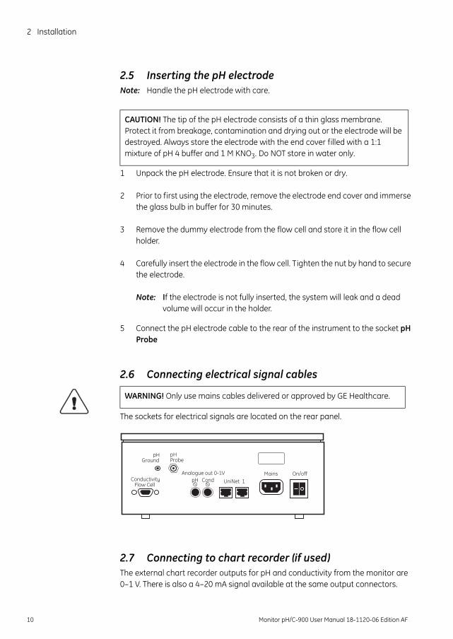
2.6 Connecting electrical signal cables
The sockets for electrical signals are located on the rear panel.
2.7 Connecting to chart recorder (if used)The external chart recorder outputs for pH and conductivity from the monitor are 0–1 V. There is also a 4–20 mA signal available at the same output connectors.
CAUTION! The tip of the pH electrode consists of a thin glass membrane. Protect it from breakage, contamination and drying out or the electrode will be destroyed. Always store the electrode with the end cover filled with a 1:1 mixture of pH 4 buffer and 1 M KNO3. Do NOT store in water only.
WARNING! Only use mains cables delivered or approved by GE Healthcare.
Analogue out 0-1VUniNet 1
Mains On/offpH CondConductivity
Flow Cell
pHProbe
pHGround
10 Monitor pH/C-900 User Manual 18-1120-06 Edition AF
Installation 2
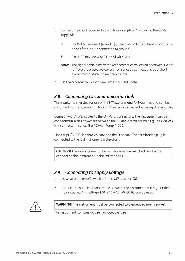
1 Connect the chart recorder to the DIN-socket pH or Cond using the cable supplied:
a. For 0–1 V use wire 1 (+) and 2 (–). Use a recorder with floating inputs (i.e. none of the inputs connected to ground).
b. For 4–20 mA use wire 5 (+) and wire 6 (–).
Note: The signal cable is delivered with protective covers on each wire. Do not remove the protective covers from unused connections as a short circuit may disturb the measurements.
2 Set the recorder to 0–1 V or 4–20 mA input, full scale.
2.8 Connecting to communication linkThe monitor is intended for use with ÄKTAexplorer and ÄKTApurifier, and can be controlled from a PC running UNICORN™ version 2.20 or higher, using UniNet cables.
Connect two UniNet cables to the UniNet 1 connectors. The instrument can be connected in series anywhere between the PC and a termination plug. The UniNet 1 link connects, in series, the PC with Pump P-900,
Monitor pH/C-900, Monitor UV-900 and the Frac-900. The termination plug is connected to the last instrument in the chain.
2.9 Connecting to supply voltage1 Make sure the on/off switch is in the OFF-position (O).
2 Connect the supplied mains cable between the instrument and a grounded mains socket. Any voltage 100–240 V AC, 50–60 Hz can be used.
The instrument contains no user replaceable fuse.
CAUTION! The mains power to the monitor must be switched OFF before connecting the instrument to the UniNet 1 link.
WARNING! The instrument must be connected to a grounded mains socket.
Monitor pH/C-900 User Manual 18-1120-06 Edition AF 11
2 Installation
2.10 Preparing the instrument for useBefore the instrument is ready to use:
• Set the conductivity cell constant, see section B.2.3.
• Calibrate the temperature sensor, see section B.2.6.
• Calibrate the pH electrode, see section 3.6.
Note: The conductivity cell constant is shown on the packaging. Retain the packaging in case the conductivity cell constant needs to be re-entered.
Note: Measured temperature is the temperature in the conductivity flow cell, which can differ from the ambient temperature.
Note: When running chromatography using organic solvents, it is recommended that the pH electrode is removed and the dummy electrode inserted in its place, as organic solvents will cause pH electrode degeneration.
Before performing these procedures you are recommended to read sections 3.1–3.3.
WARNING! The computer should be installed and used according to the instructions provided by the manufacturer of the computer.
12 Monitor pH/C-900 User Manual 18-1120-06 Edition AF
Operation 3
3 Operation
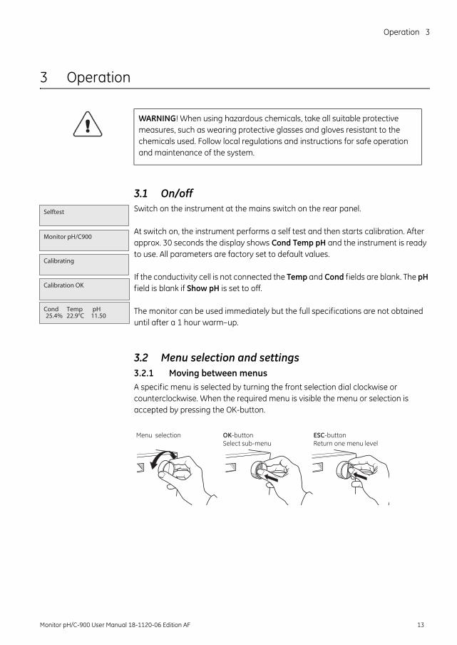
3.1 On/offSwitch on the instrument at the mains switch on the rear panel.
At switch on, the instrument performs a self test and then starts calibration. After approx. 30 seconds the display shows Cond Temp pH and the instrument is ready to use. All parameters are factory set to default values.
If the conductivity cell is not connected the Temp and Cond fields are blank. The pH field is blank if Show pH is set to off.
The monitor can be used immediately but the full specifications are not obtained until after a 1 hour warm–up.
3.2 Menu selection and settings3.2.1 Moving between menusA specific menu is selected by turning the front selection dial clockwise or counterclockwise. When the required menu is visible the menu or selection is accepted by pressing the OK-button.
WARNING! When using hazardous chemicals, take all suitable protective measures, such as wearing protective glasses and gloves resistant to the chemicals used. Follow local regulations and instructions for safe operation and maintenance of the system.
Calibrating
Selftest
Cond Temp pH25.4% 22.9°C 11.50
Monitor pH/C900
Calibration OK
Menu selection OK-button ESC-buttonSelect sub-menu Return one menu level
Monitor pH/C-900 User Manual 18-1120-06 Edition AF 13
3 Operation
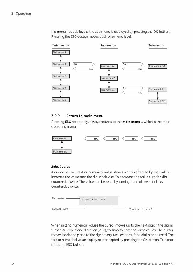
If a menu has sub levels, the sub menu is displayed by pressing the OK-button. Pressing the ESC-button moves back one menu level.
3.2.2 Return to main menuPressing ESC repeatedly, always returns to the main menu 1 which is the main operating menu.
Select value
A cursor below a text or numerical value shows what is affected by the dial. To increase the value turn the dial clockwise. To decrease the value turn the dial counterclockwise. The value can be reset by turning the dial several clicks counterclockwise.
When setting numerical values the cursor moves up to the next digit if the dial is turned quickly in one direction (22.0), to simplify entering large values. The cursor moves back one place to the right every two seconds if the dial is not turned. The text or numerical value displayed is accepted by pressing the OK-button. To cancel, press the ESC-button.
Main menu 1
Main menu 2
Main menu 3
Main menu 4
Main menu 5
Main menus Sub menus Sub menus
Sub menu 2.3.1
Sub menu 2.3.2
Sub menu 2.1
Sub menu 2.2
Sub menu 2.3
Sub menu 2 .1.1ESC
OK
ESC
OK
ESC
OK
Main menu 1
Main menu 2
ESC ESC ESC ESC
Setup Cond ref temp Parameter
Current value New value to be set
14 Monitor pH/C-900 User Manual 18-1120-06 Edition AF
Operation 3
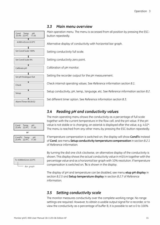
3.3 Main menu overviewMain operation menu. The menu is accessed from all position by pressing the ESC-button repeatedly.
Alternative display of conductivity with horizontal bar graph.
Setting conductivity full scale.
Setting conductivity zero point.
Calibration of pH monitor.
Setting the recorder output for the pH measurement.
Check internal operating values. See Reference information section B.1.
Setup conductivity, pH, temp., language, etc. See Reference information section B.2.
Set different timer option. See Reference information section B.3.
3.4 Reading pH and conductivity valuesThe main operating menu shows the conductivity as a percentage of full scale together with the current temperature in the flow cell, and the pH value. If the pH value is not stable or is changing, an asterisk is displayed after the value, e.g. 4.02*. The menu is reached from any other menu by pressing the ESC-button repeatedly.
If temperature compensation is switched-on, the display will show CondTc instead of Cond, see menu Setup conductivity temperature compensation in section B.2.1 of Reference information.
By turning the dial one click clockwise, an alternative display of the conductivity is shown. This display shows the actual conductivity value in mS/cm together with the percentage value and as a horizontal bar graph with 10% resolution. If temperature compensation is switched on, Tc is shown in the display.
The display of pH and temperature can be disabled, see menu etup pH display in section B.2.5 and Setup temperature display in section B.2.7 of Reference information.
3.5 Setting conductivity scaleThe monitor measures conductivity over the complete working range. No range settings are required. However, to obtain a usable output signal for a recorder, or to view the conductivity as a percentage of buffer B, it is possible to set a 0 to 100%
Set Cond Scale 100%
Calibrate pH
Set pH Analogue Out
Check
Alarm/Timer 00:30:52
Setup
Cond Temp pH25.4% 22.9°C 11.50
4.000 mS/cm 22.9°C
Set Cond Scale 0%
Cond Temp pH25.4% 22.9°C 11.50
Tc 4.000mS/cm 22.9°C
or
Bar graph
CondTc Temp pH25.4% 22.9°C 11.50
Monitor pH/C-900 User Manual 18-1120-06 Edition AF 15
3 Operation
range. This can be done with reference to the buffers used or by selecting any fixed range between 0 µS/cm and 999.9 mS/cm.
To set the scale with reference to the buffers do as follows:
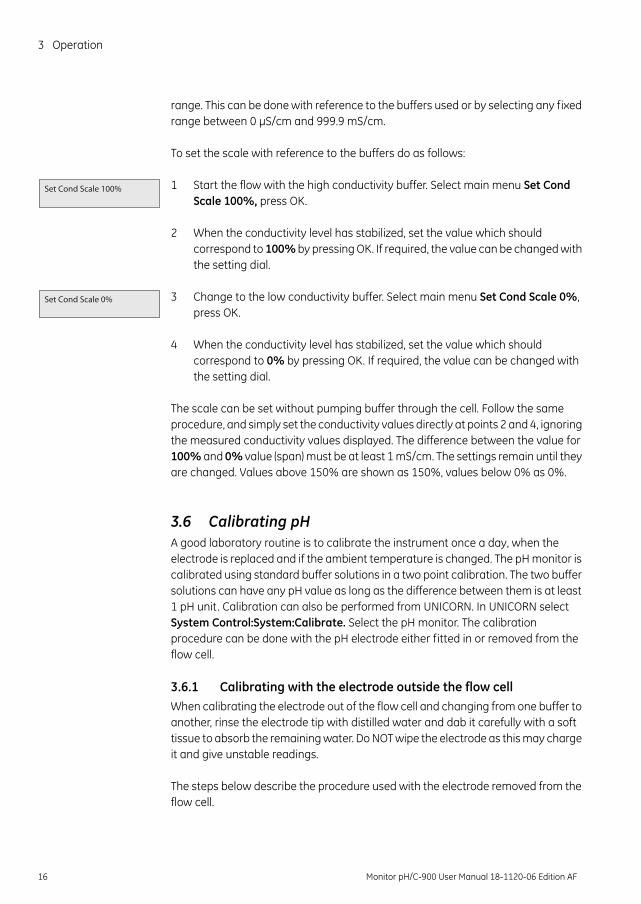
1 Start the flow with the high conductivity buffer. Select main menu Set Cond Scale 100%, press OK.
2 When the conductivity level has stabilized, set the value which should correspond to 100% by pressing OK. If required, the value can be changed with the setting dial.
3 Change to the low conductivity buffer. Select main menu Set Cond Scale 0%, press OK.
4 When the conductivity level has stabilized, set the value which should correspond to 0% by pressing OK. If required, the value can be changed with the setting dial.
The scale can be set without pumping buffer through the cell. Follow the same procedure, and simply set the conductivity values directly at points 2 and 4, ignoring the measured conductivity values displayed. The difference between the value for 100% and 0% value (span) must be at least 1 mS/cm. The settings remain until they are changed. Values above 150% are shown as 150%, values below 0% as 0%.
3.6 Calibrating pHA good laboratory routine is to calibrate the instrument once a day, when the electrode is replaced and if the ambient temperature is changed. The pH monitor is calibrated using standard buffer solutions in a two point calibration. The two buffer solutions can have any pH value as long as the difference between them is at least 1 pH unit. Calibration can also be performed from UNICORN. In UNICORN select System Control:System:Calibrate. Select the pH monitor. The calibration procedure can be done with the pH electrode either fitted in or removed from the flow cell.
3.6.1 Calibrating with the electrode outside the flow cellWhen calibrating the electrode out of the flow cell and changing from one buffer to another, rinse the electrode tip with distilled water and dab it carefully with a soft tissue to absorb the remaining water. Do NOT wipe the electrode as this may charge it and give unstable readings.
The steps below describe the procedure used with the electrode removed from the flow cell.
Set Cond Scale 100%
Set Cond Scale 0%
16 Monitor pH/C-900 User Manual 18-1120-06 Edition AF
Operation 3
Note: The Monitor must be unlocked if connected to a UNICORN control system.
1 Remove the pH electrode from the flow cell and immerse the electrode in the 1:st standard buffer solution (normally pH 7.0).
2 Select main menu Calibrate pH. The display shows the current low and high calibrated pH value. Press OK.
3 Select sub menu Calib pH Buffer 1, press OK. When the pH value has stabilized, the Please wait message will disappear.
4 Adjust the pH value in the display using the dial, so that it corresponds to the known pH value of the 1:st buffer solution, press OK. The sub menu Calib pH Buffer 2 is shown.
5 Rinse the electrode tip with distilled water and then immerse the electrode in the 2:nd standard buffer solution (e.g. 4.0 or 9.0), press OK.
6 When the pH value has stabilized, the Please wait message will disappear.
7 Adjust the pH value in the display using the dial, so that it corresponds to the known pH value of the 2:nd buffer solution, press OK.
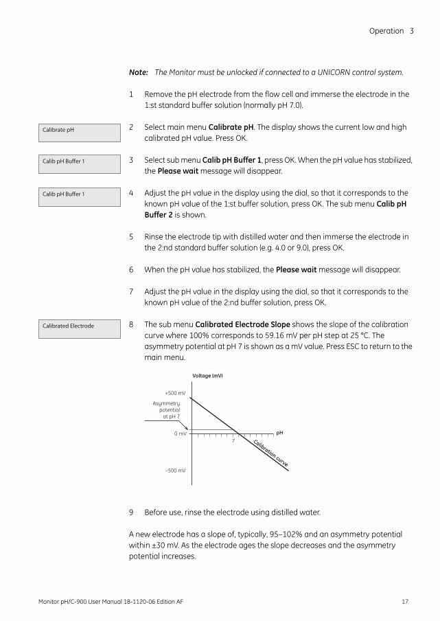
8 The sub menu Calibrated Electrode Slope shows the slope of the calibration curve where 100% corresponds to 59.16 mV per pH step at 25 °C. The asymmetry potential at pH 7 is shown as a mV value. Press ESC to return to the main menu.
9 Before use, rinse the electrode using distilled water.
A new electrode has a slope of, typically, 95–102% and an asymmetry potential within ±30 mV. As the electrode ages the slope decreases and the asymmetry potential increases.
Calibrate pH
Calib pH Buffer 1
Calib pH Buffer 1
Calibrated Electrode
Voltage (mV)
pH0 mV
+500 mV
–500 mV
7
Asymmetrypotential
at pH 7
Calibration curve
Monitor pH/C-900 User Manual 18-1120-06 Edition AF 17
3 Operation
As a rule, when an electrode has an asymmetry potential outside of ±60 mV and a slope lower than 80%, and no improvement can be achieved by cleaning, it should be replaced.
An electrode is still usable at lower slopes and higher asymmetry potentials but the response will be slower and the accuracy diminish.
3.6.2 Calibrating with the electrode in the flow cellWhen calibrating with the electrode fitted in the flow cell in ÄKTApurifier, follow the above procedure. Before adjusting the pH monitor, ensure that the pH has stabilized. Leave the pump running while calibrating. Switch to the other standard buffer solution and repeat the procedure. For a description of calibration from UNICORN with the electrode fitted in the flow cell, see section 6.6 in UNICORN User Manual.
3.7 Calibrating conductivityThe cell constant for the particular flow cell is written on the flow cell packaging. Refer to section B.2.3 in Reference information for how to enter the cell constant.
Adjustment of the cell constant is only necessary when the monitor is to be used to determine specific conductivity with high accuracy. The procedure is described in Reference information section B.2.2. Calibration can also be performed from UNICORN.
3.8 Using an external chart recorderThe external chart recorder outputs for pH and conductivity from the monitor are 0–1 V. There is also a 4–20 mA signal available at the same output connectors.
For the conductivity signal, 0% represents 0 V and 100% represents 1 V as set under main menus Set Cond scale 0% and Set Cond scale 100%.
For the pH signal, the full scale and zero level has to be set according to below.
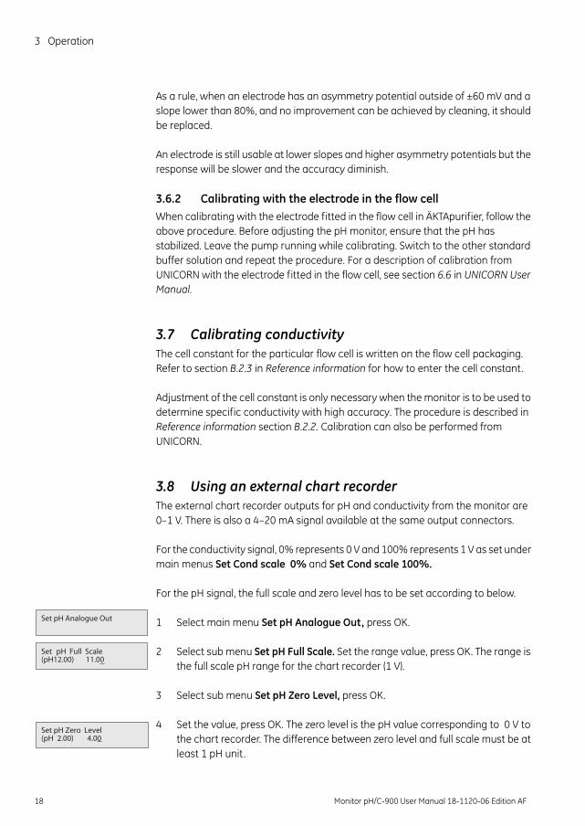
1 Select main menu Set pH Analogue Out, press OK.
2 Select sub menu Set pH Full Scale. Set the range value, press OK. The range is the full scale pH range for the chart recorder (1 V).
3 Select sub menu Set pH Zero Level, press OK.
4 Set the value, press OK. The zero level is the pH value corresponding to 0 V to the chart recorder. The difference between zero level and full scale must be at least 1 pH unit.
Set pH Full Scale (pH12.00) 11.00
Set pH Analogue Out
Set pH Zero Level (pH 2.00) 4.00
18 Monitor pH/C-900 User Manual 18-1120-06 Edition AF
Operation 3
3.9 Storage and shut-down
3.9.1 Storage of conductivity flow cellOvernight: The conductivity cell can be left filled with a buffer.
Weekend or Long time storage: Flush the conductivity cell with water and fill with 20% ethanol.
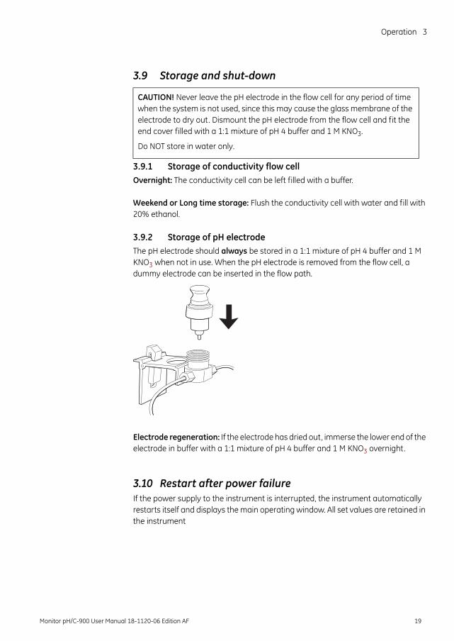
3.9.2 Storage of pH electrode The pH electrode should always be stored in a 1:1 mixture of pH 4 buffer and 1 M KNO3 when not in use. When the pH electrode is removed from the flow cell, a dummy electrode can be inserted in the flow path.
Electrode regeneration: If the electrode has dried out, immerse the lower end of the electrode in buffer with a 1:1 mixture of pH 4 buffer and 1 M KNO3 overnight.
3.10 Restart after power failureIf the power supply to the instrument is interrupted, the instrument automatically restarts itself and displays the main operating window. All set values are retained in the instrument
CAUTION! Never leave the pH electrode in the flow cell for any period of time when the system is not used, since this may cause the glass membrane of the electrode to dry out. Dismount the pH electrode from the flow cell and fit the end cover filled with a 1:1 mixture of pH 4 buffer and 1 M KNO3.
Do NOT store in water only.
Monitor pH/C-900 User Manual 18-1120-06 Edition AF 19
4 Maintenance
4 Maintenance
4.1 Periodic maintenance
4.2 Cleaning the flow cellRemove the pH electrode and install the dummy electrode in the pH flow cell.
Pump a cleaning or sanitizing agent through the flow cells. The standard recommendation is to pump 1 M NaOH for 30 minutes and then wash out with buffer.
WARNING! Disconnect the power supply before attempting to replace any item on the instrument during maintenance.
CAUTION! Only spare parts approved or supplied by GE Healthcare may be used for maintaining and servicing the instrument.
WARNING! Remove liquid or dirt from the system surface using a cloth and, if necessary, a mild cleaning agent. Do not use strong detergents.
WARNING! When using hazardous chemicals, make sure that the entire system has been flushed thoroughly with bacteriostatic solution, e.g. NaOH, and distilled water before service and maintenance.
Interval Action (see procedures below)Every 6 month or more often if required Change pH electrode
Check that the power cord is whole and undamaged. It shall be replaced if any sign of damage is detected.
When required Clean the conductivity cell Clean the pH electrode
WARNING! NaOH is injurious to health. Avoid spillage and use protective clothing and equipment.
20 Monitor pH/C-900 User Manual 18-1120-06 Edition AF
Maintenance 4
4.3 Cleaning the pH electrodeNote: The pH electrode has a limited life length and should be replaced every six
months or when the response time is slow.
Use one of the following procedures to clean the electrode to improve the response:
• Salt deposits: Dissolve the deposit by immersing the electrode first in 0.1 M HCl, then in 0.1 M NaOH, and again in 0.1 M HCl. Each immersion is for a 5 minute period. Rinse electrode tip in distilled water between each solution.
• Oil or Grease Films: Wash electrode tip in a liquid detergent and water. If film is known to be soluble in a particular organic solvent, wash with this solvent. Rinse electrode tip in distilled water.
• Protein deposits: Dissolve the deposit by immersing the electrode in a 1% pepsin solution, in 0.1 M HCl, for five minutes, followed by thorough rinsing with distilled water.
If these procedures fail to rejuvenate the electrode, the problem is most likely a clogged liquid junction.
1 Heat a 1 M KNO3 solution to 60–80°C.
2 Place the electrode tip in the heated KNO3 solution.
3 Allow the electrode to cool while immersed in the KNO3 solution before re-testing.
If these steps fail to improve the electrode response, replace the electrode.
4.4 Changing pH electrodeSee section 2.4 Installing the pH electrode.
WARNING! Always use protective equipment when handling dangerous chemicals.
Monitor pH/C-900 User Manual 18-1120-06 Edition AF 21
4 Maintenance
4.5 Cleaning the conductivity flow cell
If the conductivity measurements are not comparable to previous results, the electrodes in the flow cell may be contaminated and require cleaning. To clean the flow cell:
1 Pump 15 ml of 1 M NaOH at 1 ml/min through the flow cell either by using a pump or a syringe.
2 Leave it for 15 minutes.
3 Rinse thoroughly with 50 ml de-ionized water.
Note: If the flow cell is totally blocked, the blockage can be broken using a thin needle or a piece of string with a diameter less than 0.8 mm.
4.6 Changing conductivity flow cellsThe flow cells can be changed when required. Make sure the instrument is switched off, before disconnecting/connecting the cells to the rear of the instrument housing.
1 If the cell is replaced with a new flow cell, the monitor must be calibrated with the new cell constant value which is written on the flow cell package. See sub menu Setup conductivity in section B.2.3 in Reference information. If the cell constant is not known, it can be determined (see section B.2.2 in Reference information).
4.7 Instrument housingWipe the instrument housing regularly with a damp cloth. Let the instrument dry completely before use.
WARNING! When using hazardous chemicals, make sure that the entire system has been flushed thoroughly with bacteriostatic solution, e.g. NaOH, and distilled water before service and maintenance.
22 Monitor pH/C-900 User Manual 18-1120-06 Edition AF
Trouble shooting 5
5 Trouble shooting
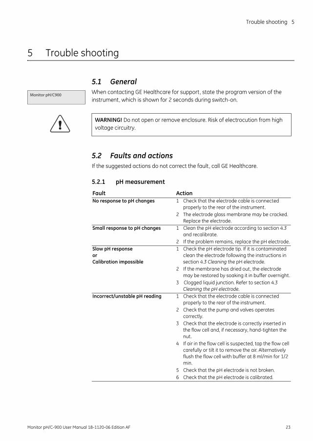
5.1 GeneralWhen contacting GE Healthcare for support, state the program version of the instrument, which is shown for 2 seconds during switch-on.
5.2 Faults and actionsIf the suggested actions do not correct the fault, call GE Healthcare.
5.2.1 pH measurement
Monitor pH/C900
WARNING! Do not open or remove enclosure. Risk of electrocution from high voltage circuitry.
Fault ActionNo response to pH changes 1 Check that the electrode cable is connected
properly to the rear of the instrument.2 The electrode glass membrane may be cracked.
Replace the electrode.Small response to pH changes 1 Clean the pH electrode according to section 4.3
and recalibrate.2 If the problem remains, replace the pH electrode.
Slow pH response or Calibration impossible
1 Check the pH electrode tip. If it is contaminated clean the electrode following the instructions in section 4.3 Cleaning the pH electrode.
2 If the membrane has dried out, the electrode may be restored by soaking it in buffer overnight.
3 Clogged liquid junction. Refer to section 4.3 Cleaning the pH electrode.
Incorrect/unstable pH reading 1 Check that the electrode cable is connected properly to the rear of the instrument.
2 Check that the pump and valves operates correctly.
3 Check that the electrode is correctly inserted in the flow cell and, if necessary, hand-tighten the nut.
4 If air in the flow cell is suspected, tap the flow cell carefully or tilt it to remove the air. Alternatively flush the flow cell with buffer at 8 ml/min for 1/2 min.
5 Check that the pH electrode is not broken. 6 Check that the pH electrode is calibrated.
Monitor pH/C-900 User Manual 18-1120-06 Edition AF 23
5 Trouble shooting
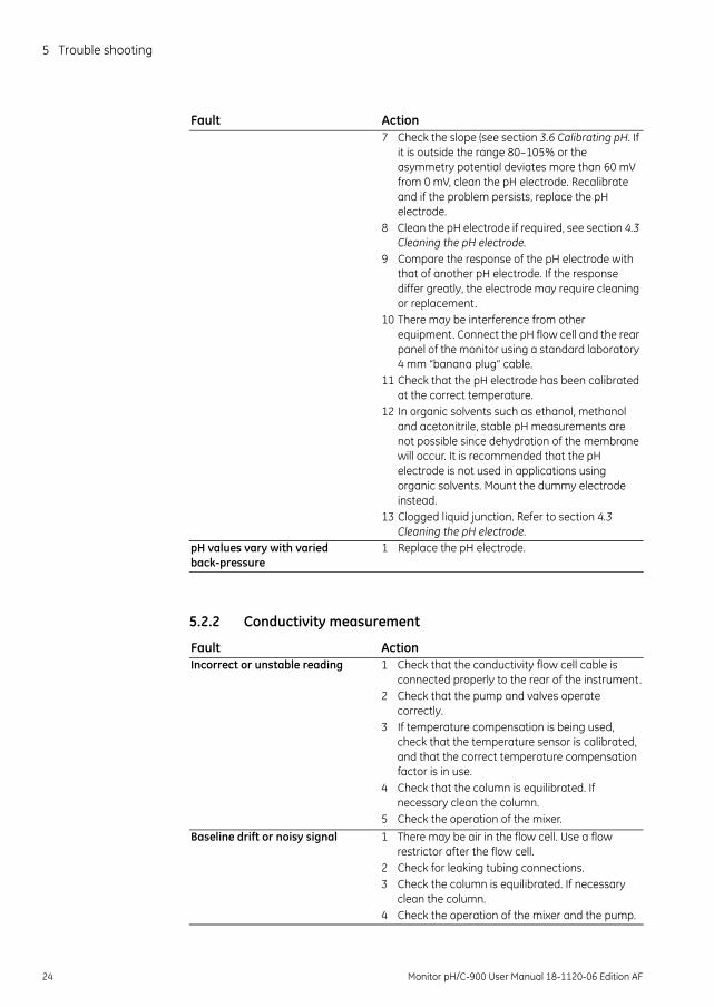
5.2.2 Conductivity measurement
7 Check the slope (see section 3.6 Calibrating pH. If it is outside the range 80–105% or the asymmetry potential deviates more than 60 mV from 0 mV, clean the pH electrode. Recalibrate and if the problem persists, replace the pH electrode.
8 Clean the pH electrode if required, see section 4.3 Cleaning the pH electrode.
9 Compare the response of the pH electrode with that of another pH electrode. If the response differ greatly, the electrode may require cleaning or replacement.
10 There may be interference from other equipment. Connect the pH flow cell and the rear panel of the monitor using a standard laboratory 4 mm “banana plug” cable.
11 Check that the pH electrode has been calibrated at the correct temperature.
12 In organic solvents such as ethanol, methanol and acetonitrile, stable pH measurements are not possible since dehydration of the membrane will occur. It is recommended that the pH electrode is not used in applications using organic solvents. Mount the dummy electrode instead.
13 Clogged liquid junction. Refer to section 4.3 Cleaning the pH electrode.
pH values vary with varied back-pressure
1 Replace the pH electrode.
Fault Action
Fault ActionIncorrect or unstable reading 1 Check that the conductivity flow cell cable is
connected properly to the rear of the instrument.2 Check that the pump and valves operate
correctly.3 If temperature compensation is being used,
check that the temperature sensor is calibrated, and that the correct temperature compensation factor is in use.
4 Check that the column is equilibrated. If necessary clean the column.
5 Check the operation of the mixer.Baseline drift or noisy signal 1 There may be air in the flow cell. Use a flow
restrictor after the flow cell.2 Check for leaking tubing connections.3 Check the column is equilibrated. If necessary
clean the column.4 Check the operation of the mixer and the pump.
24 Monitor pH/C-900 User Manual 18-1120-06 Edition AF
Trouble shooting 5
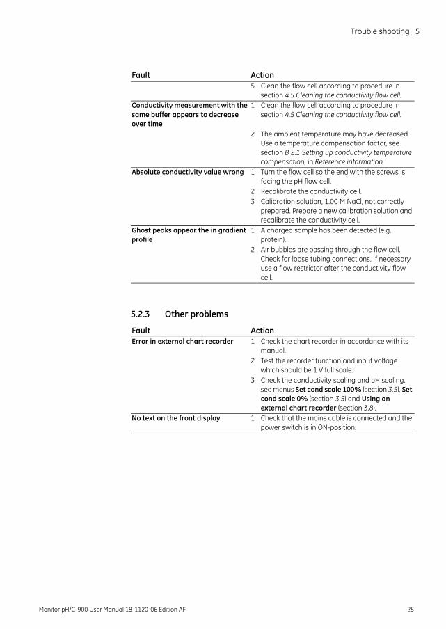
5.2.3 Other problems
5 Clean the flow cell according to procedure in section 4.5 Cleaning the conductivity flow cell.
Conductivity measurement with the same buffer appears to decrease over time
1 Clean the flow cell according to procedure in section 4.5 Cleaning the conductivity flow cell.
2 The ambient temperature may have decreased. Use a temperature compensation factor, see section B 2.1 Setting up conductivity temperature compensation, in Reference information.
Absolute conductivity value wrong 1 Turn the flow cell so the end with the screws is facing the pH flow cell.
2 Recalibrate the conductivity cell.3 Calibration solution, 1.00 M NaCl, not correctly
prepared. Prepare a new calibration solution and recalibrate the conductivity cell.
Ghost peaks appear the in gradient profile
1 A charged sample has been detected (e.g. protein).
2 Air bubbles are passing through the flow cell. Check for loose tubing connections. If necessary use a flow restrictor after the conductivity flow cell.
Fault Action
Fault ActionError in external chart recorder 1 Check the chart recorder in accordance with its
manual.2 Test the recorder function and input voltage
which should be 1 V full scale.3 Check the conductivity scaling and pH scaling,
see menus Set cond scale 100% (section 3.5), Set cond scale 0% (section 3.5) and Using an external chart recorder (section 3.8).
No text on the front display 1 Check that the mains cable is connected and the power switch is in ON-position.
Monitor pH/C-900 User Manual 18-1120-06 Edition AF 25
5 Trouble shooting
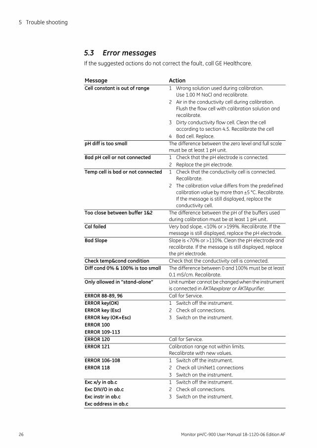
5.3 Error messagesIf the suggested actions do not correct the fault, call GE Healthcare.
Message ActionCell constant is out of range 1 Wrong solution used during calibration.
Use 1.00 M NaCl and recalibrate.2 Air in the conductivity cell during calibration.
Flush the flow cell with calibration solution and recalibrate.
3 Dirty conductivity flow cell. Clean the cell according to section 4.5. Recalibrate the cell
4 Bad cell. Replace.pH diff is too small The difference between the zero level and full scale
must be at least 1 pH unit.Bad pH cell or not connected 1 Check that the pH electrode is connected.
2 Replace the pH electrode.Temp cell is bad or not connected 1 Check that the conductivity cell is connected.
Recalibrate.2 The calibration value differs from the predefined
calibration value by more than ±5 °C. Recalibrate. If the message is still displayed, replace the conductivity cell.
Too close between buffer 1&2 The difference between the pH of the buffers used during calibration must be at least 1 pH unit.
Cal failed Very bad slope, <10% or >199%. Recalibrate. If the message is still displayed, replace the pH electrode.
Bad Slope Slope is <70% or >110%. Clean the pH electrode and recalibrate. If the message is still displayed, replace the pH electrode.
Check temp&cond condition Check that the conductivity cell is connected.Diff cond 0% & 100% is too small The difference between 0 and 100% must be at least
0.1 mS/cm. Recalibrate.Only allowed in ”stand-alone” Unit number cannot be changed when the instrument
is connected in ÄKTAexplorer or ÄKTApurifier.ERROR 88-89, 96 Call for Service.ERROR key(OK) 1 Switch off the instrument.ERROR key (Esc) 2 Check all connections.ERROR key (OK+Esc) 3 Switch on the instrument.ERROR 100ERROR 109-113ERROR 120 Call for Service.ERROR 121 Calibration range not within limits.
Recalibrate with new values.ERROR 106-108 1 Switch off the instrument.ERROR 118 2 Check all UniNet1 connections
3 Switch on the instrument.Exc x/y in ab.c 1 Switch off the instrument.Exc DIV/O in ab.c 2 Check all connections.Exc instr in ab.c 3 Switch on the instrument.Exc address in ab.c
26 Monitor pH/C-900 User Manual 18-1120-06 Edition AF
Reference information A
A Description
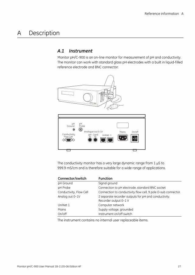
A.1 InstrumentMonitor pH/C-900 is an on-line monitor for measurement of pH and conductivity. The monitor can work with standard glass pH electrodes with a built in liquid-filled reference electrode and BNC connector.
The conductivity monitor has a very large dynamic range from 1 µS to 999.9 mS/cm and is therefore suitable for a wide range of applications.
The instrument contains no internal user replaceable items.
p H / C - 9 0 0
Analogue out 0-1VUniNet 1
Mains On/offpH CondConductivity
Flow Cell
pHProbe
pHGround
Connector/switch FunctionpH Ground Signal ground pH Probe Connection to pH electrode, standard BNC socketConductivity, Flow Cell Connection to conductivity flow cell, 9 pole D-sub connector.Analog out 0–1V 2 separate recorder outputs for pH and conductivity.
Recorder output 0–1 VUniNet 1 Computer networkMains Supply voltage, groundedOn/off Instrument on/off switch
Monitor pH/C-900 User Manual 18-1120-06 Edition AF 27
A Description
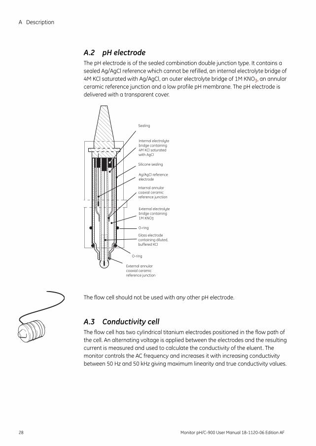
A.2 pH electrodeThe pH electrode is of the sealed combination double junction type. It contains a sealed Ag/AgCl reference which cannot be refilled, an internal electrolyte bridge of 4M KCl saturated with Ag/AgCl, an outer electrolyte bridge of 1M KNO3, an annular ceramic reference junction and a low profile pH membrane. The pH electrode is delivered with a transparent cover.
The flow cell should not be used with any other pH electrode.
A.3 Conductivity cellThe flow cell has two cylindrical titanium electrodes positioned in the flow path of the cell. An alternating voltage is applied between the electrodes and the resulting current is measured and used to calculate the conductivity of the eluent. The monitor controls the AC frequency and increases it with increasing conductivity between 50 Hz and 50 kHz giving maximum linearity and true conductivity values.
Sealing
Internal electrolytebridge containing4M KCl saturatedwith AgCl
Silicone sealing
Internal annularcoaxial ceramicreference junction
External electrolytebridge containing1M KNO3
O-ring
Glass electrodecontaining diluted,buffered KCl
External annularcoaxial ceramicreference junction
O-ring
Ag/AgCl referenceelectrode
28 Monitor pH/C-900 User Manual 18-1120-06 Edition AF
Reference information A
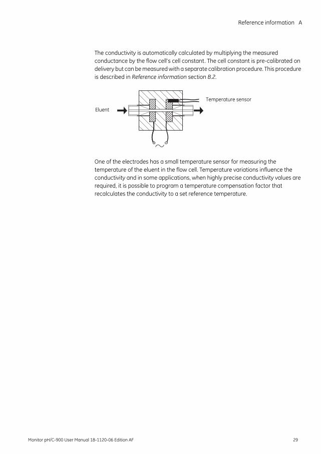
The conductivity is automatically calculated by multiplying the measured conductance by the flow cell’s cell constant. The cell constant is pre-calibrated on delivery but can be measured with a separate calibration procedure. This procedure is described in Reference information section B.2.
One of the electrodes has a small temperature sensor for measuring the temperature of the eluent in the flow cell. Temperature variations influence the conductivity and in some applications, when highly precise conductivity values are required, it is possible to program a temperature compensation factor that recalculates the conductivity to a set reference temperature.
Eluent
Temperature sensor
Monitor pH/C-900 User Manual 18-1120-06 Edition AF 29
B Reference information
B Menus
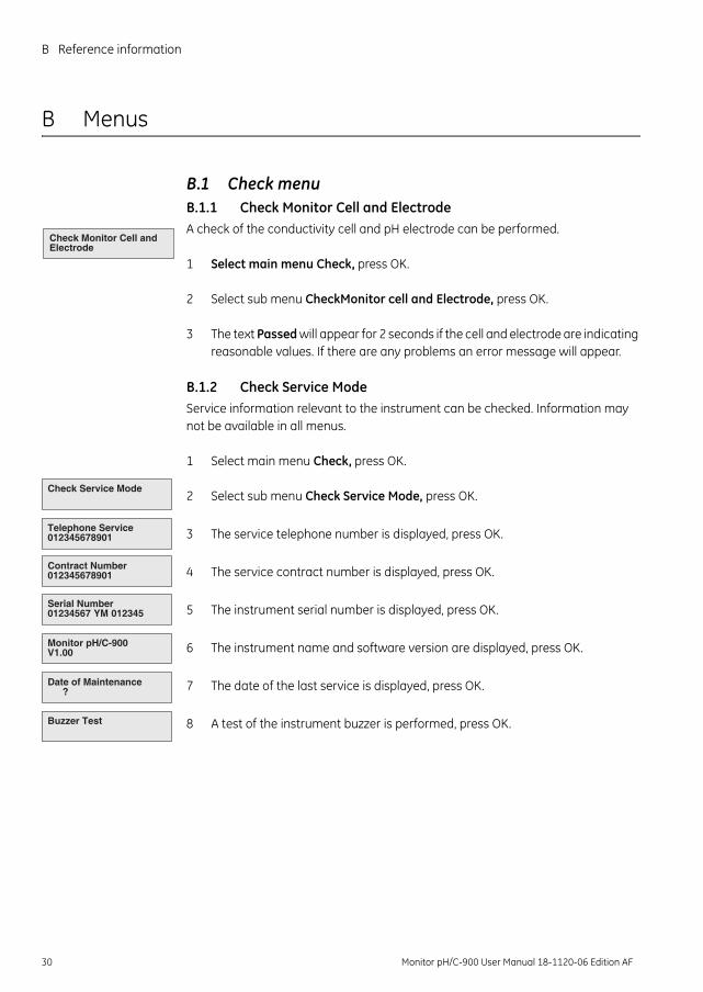
B.1 Check menuB.1.1 Check Monitor Cell and ElectrodeA check of the conductivity cell and pH electrode can be performed.
1 Select main menu Check, press OK.
2 Select sub menu CheckMonitor cell and Electrode, press OK.
3 The text Passed will appear for 2 seconds if the cell and electrode are indicating reasonable values. If there are any problems an error message will appear.
B.1.2 Check Service ModeService information relevant to the instrument can be checked. Information may not be available in all menus.
1 Select main menu Check, press OK.
2 Select sub menu Check Service Mode, press OK.
3 The service telephone number is displayed, press OK.
4 The service contract number is displayed, press OK.
5 The instrument serial number is displayed, press OK.
6 The instrument name and software version are displayed, press OK.
7 The date of the last service is displayed, press OK.
8 A test of the instrument buzzer is performed, press OK.
Check Monitor Cell and Electrode
Check Service Mode
Telephone Service 012345678901
Contract Number012345678901
Buzzer Test
Date of Maintenance ?
Monitor pH/C-900V1.00
Serial Number 01234567 YM 012345
30 Monitor pH/C-900 User Manual 18-1120-06 Edition AF
Reference information B
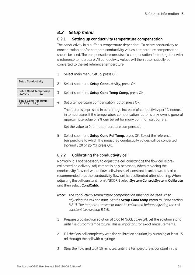
B.2 Setup menuB.2.1 Setting up conductivity temperature compensationThe conductivity in a buffer is temperature dependent. To relate conductivity to concentration and/or compare conductivity values, temperature compensation should be used. The compensation consists of a compensation factor together with a reference temperature. All conductivity values will then automatically be converted to the set reference temperature.
1 Select main menu Setup, press OK.
2 Select sub menu Setup Conductivity, press OK.
3 Select sub menu Setup Cond Temp Comp, press OK.
4 Set a temperature compensation factor, press OK.
The factor is expressed in percentage increase of conductivity per °C increase in temperature. If the temperature compensation factor is unknown, a general approximate value of 2% can be set for many common salt buffers.
Set the value to 0 for no temperature compensation.
5 Select sub menu Setup Cond Ref Temp, press OK. Select the reference temperature to which the measured conductivity values will be converted (normally 20 or 25 °C), press OK.
B.2.2 Calibrating the conductivity cellNormally it is not necessary to adjust the cell constant as the flow cell is pre-calibrated on delivery. Adjustment is only necessary when replacing the conductivity flow cell with a flow cell whose cell constant is unknown. It is also recommended that the conductivity flow cell is recalibrated after cleaning. When adjusting the cell constant from UNICORN select System Control:System: Calibrate and then select CondCalib.
Note: The conductivity temperature compensation must not be used when adjusting the cell constant. Set the Setup Cond temp comp to 0 (see section B.2.1). The temperature sensor must be calibrated before adjusting the cell constant (see section B.2.6).
1 Prepare a calibration solution of 1.00 M NaCl, 58.44 g/l. Let the solution stand until it is at room temperature. This is important for exact measurements.
2 Fill the flow cell completely with the calibration solution, by pumping at least 15 ml through the cell with a syringe.
3 Stop the flow and wait 15 minutes, until the temperature is constant in the
Setup Conductivity
Setup Cond Temp Comp (2.0%/°C) 2.0
Setup Cond Ref Temp (22.3°C) 25.0
Monitor pH/C-900 User Manual 18-1120-06 Edition AF 31
B Reference information
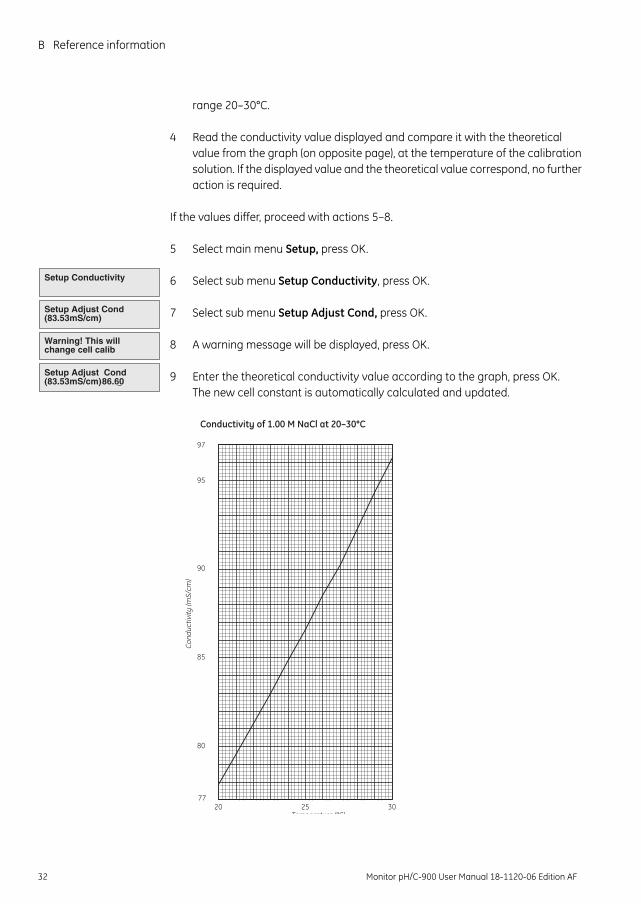
range 20–30°C.
4 Read the conductivity value displayed and compare it with the theoretical value from the graph (on opposite page), at the temperature of the calibration solution. If the displayed value and the theoretical value correspond, no further action is required.
If the values differ, proceed with actions 5–8.
5 Select main menu Setup, press OK.
6 Select sub menu Setup Conductivity, press OK.
7 Select sub menu Setup Adjust Cond, press OK.
8 A warning message will be displayed, press OK.
9 Enter the theoretical conductivity value according to the graph, press OK. The new cell constant is automatically calculated and updated.
Setup Adjust Cond (83.53mS/cm)
Setup Adjust Cond (83.53mS/cm) 86.60
Warning! This will change cell calib
Setup Conductivity
20 25 3077
80
85
90
95
97
Temperature (°C)
Con
duct
ivity
(mS/
cm)
Conductivity of 1.00 M NaCl at 20–30°C
32 Monitor pH/C-900 User Manual 18-1120-06 Edition AF
Reference information B
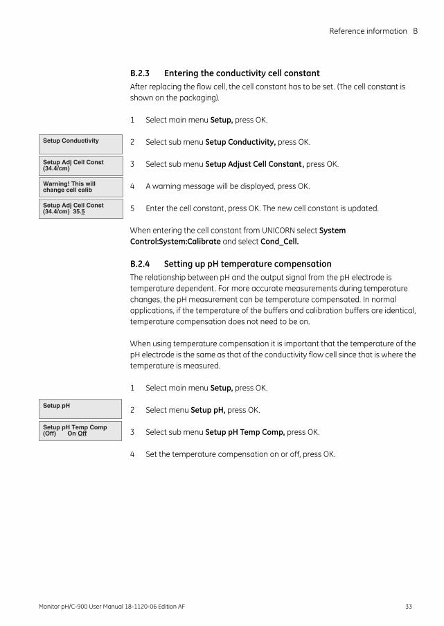
B.2.3 Entering the conductivity cell constantAfter replacing the flow cell, the cell constant has to be set. (The cell constant is shown on the packaging).
1 Select main menu Setup, press OK.
2 Select sub menu Setup Conductivity, press OK.
3 Select sub menu Setup Adjust Cell Constant, press OK.
4 A warning message will be displayed, press OK.
5 Enter the cell constant, press OK. The new cell constant is updated.
When entering the cell constant from UNICORN select System Control:System:Calibrate and select Cond_Cell.
B.2.4 Setting up pH temperature compensationThe relationship between pH and the output signal from the pH electrode is temperature dependent. For more accurate measurements during temperature changes, the pH measurement can be temperature compensated. In normal applications, if the temperature of the buffers and calibration buffers are identical, temperature compensation does not need to be on.
When using temperature compensation it is important that the temperature of the pH electrode is the same as that of the conductivity flow cell since that is where the temperature is measured.
1 Select main menu Setup, press OK.
2 Select menu Setup pH, press OK.
3 Select sub menu Setup pH Temp Comp, press OK.
4 Set the temperature compensation on or off, press OK.
Setup Adj Cell Const (34.4/cm) 35.5
Warning! This will change cell calib
Setup Adj Cell Const (34.4/cm)
Setup Conductivity
Setup pH Temp Comp (Off) On Off
Setup pH
Monitor pH/C-900 User Manual 18-1120-06 Edition AF 33
B Reference information
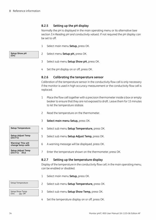
B.2.5 Setting up the pH displayNormally the pH is displayed in the main operating menu or its alternative (see section 3.4 Reading pH and conductivity values). If not required the pH display can be set to off.
1 Select main menu Setup, press OK.
2 Select menu Setup pH, press OK.
3 Select sub menu Setup Show pH, press OK.
4 Set the pH display on or off, press OK.
B.2.6 Calibrating the temperature sensor Calibration of the temperature sensor in the conductivity flow cell is only necessary if the monitor is used in high accuracy measurement or the conductivity flow cell is replaced.
1 Place the flow cell together with a precision thermometer inside a box or empty beaker to ensure that they are not exposed to draft. Leave them for 15 minutes to let the temperature stabize.
2 Read the temperature on the thermometer.
3 Select main menu Setup, press OK.
4 Select sub menu Setup Temperature, press OK.
5 Select sub menu Setup Adjust Temp, press OK.
6 A warning message will be displayed, press OK.
7 Enter the temperature shown on the thermometer, press OK.
B.2.7 Setting up the temperature displayDisplay of the temperature in the conductivity flow cell, in the main operating menu, can be enabled or disabled.
1 Select main menu Setup, press OK.
2 Select sub menu Setup Temperature, press OK.
3 Select sub menu Setup Show Temp, press OK.
4 Set the temperature display on or off, press OK.
Setup Show pH (On)
Warning! This will change temp calib
Setup Adjust Temp (23.5°C)
Setup Temperature
Setup Adjust Temp (23.5°C) 25.0
Setup Temperature
Setup Show Temp (On) On Off
34 Monitor pH/C-900 User Manual 18-1120-06 Edition AF
Reference information B
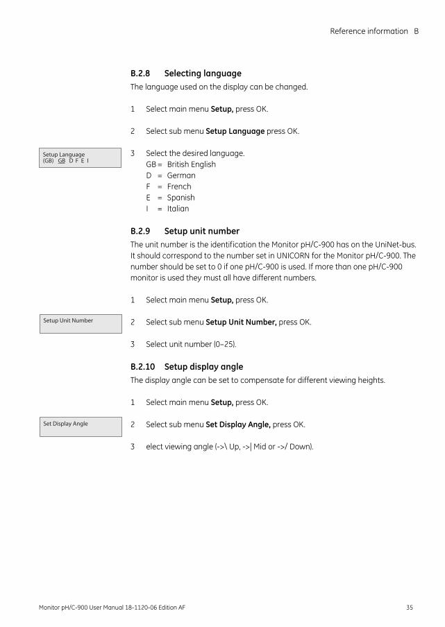
B.2.8 Selecting languageThe language used on the display can be changed.
1 Select main menu Setup, press OK.
2 Select sub menu Setup Language press OK.
3 Select the desired language.GB = British EnglishD = GermanF = FrenchE = SpanishI = Italian
B.2.9 Setup unit numberThe unit number is the identification the Monitor pH/C-900 has on the UniNet-bus. It should correspond to the number set in UNICORN for the Monitor pH/C-900. The number should be set to 0 if one pH/C-900 is used. If more than one pH/C-900 monitor is used they must all have different numbers.
1 Select main menu Setup, press OK.
2 Select sub menu Setup Unit Number, press OK.
3 Select unit number (0–25).
B.2.10 Setup display angleThe display angle can be set to compensate for different viewing heights.
1 Select main menu Setup, press OK.
2 Select sub menu Set Display Angle, press OK.
3 elect viewing angle (->\ Up, ->| Mid or ->/ Down).
Setup Language (GB) GB D F E I
Setup Unit Number
Set Display Angle
Monitor pH/C-900 User Manual 18-1120-06 Edition AF 35
B Reference information
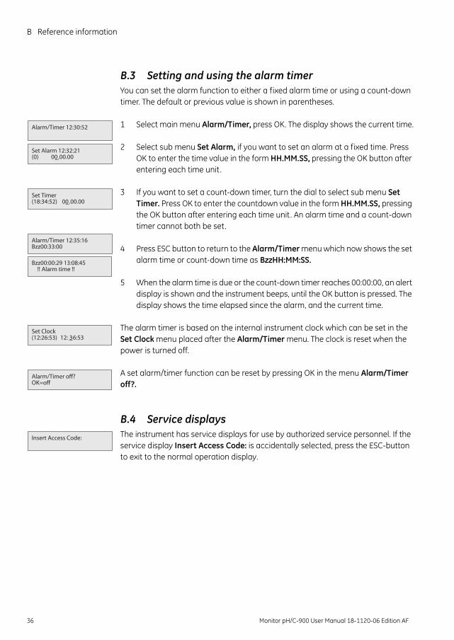
B.3 Setting and using the alarm timerYou can set the alarm function to either a fixed alarm time or using a count-down timer. The default or previous value is shown in parentheses.
1 Select main menu Alarm/Timer, press OK. The display shows the current time.
2 Select sub menu Set Alarm, if you want to set an alarm at a fixed time. Press OK to enter the time value in the form HH.MM.SS, pressing the OK button after entering each time unit.
3 If you want to set a count-down timer, turn the dial to select sub menu Set Timer. Press OK to enter the countdown value in the form HH.MM.SS, pressing the OK button after entering each time unit. An alarm time and a count-down timer cannot both be set.
4 Press ESC button to return to the Alarm/Timer menu which now shows the set alarm time or count-down time as BzzHH:MM:SS.
5 When the alarm time is due or the count-down timer reaches 00:00:00, an alert display is shown and the instrument beeps, until the OK button is pressed. The display shows the time elapsed since the alarm, and the current time.
The alarm timer is based on the internal instrument clock which can be set in the Set Clock menu placed after the Alarm/Timer menu. The clock is reset when the power is turned off.
A set alarm/timer function can be reset by pressing OK in the menu Alarm/Timer off?.
B.4 Service displaysThe instrument has service displays for use by authorized service personnel. If the service display Insert Access Code: is accidentally selected, press the ESC-button to exit to the normal operation display.
Alarm/Timer 12:30:52
Set Alarm 12:32:21 (0) 00.00.00
Set Timer (18:34:52) 00.00.00
Alarm/Timer 12:35:16 Bzz00:33:00
Bzz00:00:29 13:08:45 !! Alarm time !!
Set Clock (12:26:53) 12: 36:53
Alarm/Timer off? OK=off
Insert Access Code:
36 Monitor pH/C-900 User Manual 18-1120-06 Edition AF
Reference information B
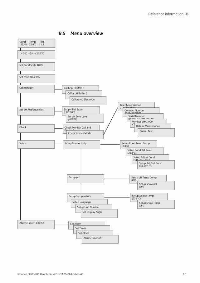
B.5 Menu overview
Check
Setup
Alarm/Timer 12:30:52
Set Cond Scale 100%
Calibrate pH
Set pH Analogue Out
Cond Temp pH25.4% 22.9°C 11.5
4.000 mS/cm 22.9°C
Set cond scale 0%
Setup Cond Temp Comp (2.0%)
Setup Cond Ref Temp (22.3°C)
Setup Adjust Cond (34565mS/cm)
Setup Adj Cell Const (34.4cm -1)
Setup Adjust Temp (23.5°C)
Setup Show Temp (On)
Setup Conductivity
Calibr pH Buffer 1
Calibr pH Buffer 2
Calibrated Electrode
Set pH Full Scale (pH12.00)
Set pH Zero Level (pH2.00)
Setup pH Temp Comp (Off)
Setup Temperature
Setup Language
Setup Unit Number
Setup Show pH (On)
Setup pH
Set Alarm
Set Timer
Set Clock
Alarm/Timer off?
Telephone Service 012345678901
Contract Number 012345678901
Serial Number01234567 YM 012345
Monitor pH/C-900 V1.00
Date of Maintenance ?Buzzer Test
Check Monitor Cell and Electrod e
Check Service Mode
Set Display Angle
Monitor pH/C-900 User Manual 18-1120-06 Edition AF 37
C Reference information
C Technical specifications
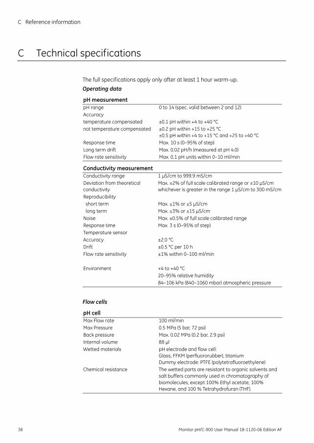
The full specifications apply only after at least 1 hour warm-up.Operating data
Flow cells
pH measurementpH range 0 to 14 (spec. valid between 2 and 12)Accuracytemperature compensated ±0.1 pH within +4 to +40 °Cnot temperature compensated ±0.2 pH within +15 to +25 °C
±0.5 pH within +4 to +15 °C and +25 to +40 °CResponse time Max. 10 s (0–95% of step)Long term drift Max. 0.02 pH/h (measured at pH 4.0)Flow rate sensitivity Max. 0.1 pH units within 0–10 ml/min
Conductivity measurementConductivity range 1 µS/cm to 999.9 mS/cm Deviation from theoretical conductivity
Max. ±2% of full scale calibrated range or ±10 µS/cm whichever is greater in the range 1 µS/cm to 300 mS/cm
Reproducibility short term Max. ±1% or ±5 µS/cm long term Max. ±3% or ±15 µS/cmNoise Max. ±0.5% of full scale calibrated range Response time Max. 3 s (0–95% of step)Temperature sensorAccuracy ±2.0 °CDrift ±0.5 °C per 10 hFlow rate sensitivity ±1% within 0–100 ml/min
Environment +4 to +40 °C20–95% relative humidity84–106 kPa (840–1060 mbar) atmospheric pressure
pH cellMax Flow rate 100 ml/minMax Pressure 0.5 MPa (5 bar, 72 psi)Back pressure Max. 0.02 MPa (0.2 bar, 2.9 psi)Internal volume 88 µlWetted materials pH electrode and flow cell:
Glass, FFKM (perfluororubber), titaniumDummy electrode: PTFE (polytetrafluoroethylene)
Chemical resistance The wetted parts are resistant to organic solvents and salt buffers commonly used in chromatography of biomolecules, except 100% Ethyl acetate, 100% Hexane, and 100 % Tetrahydrofuran (THF).
38 Monitor pH/C-900 User Manual 18-1120-06 Edition AF
Reference information C
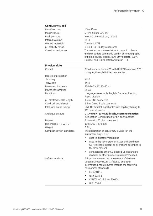
Conductivity cellMax Flow rate 100 ml/minMax Pressure 5 MPa (50 bar, 725 psi)Back pressure Max. 0.01 MPa (0.1 bar, 1.5 psi)Internal volume 14 µlWetted materials Titanium, CTFEpH stability range 1–13, 1–14 (<1 days exposure)Chemical resistance The wetted parts are resistant to organic solvents
and salt buffers commonly used in chromatography of biomolecules, except 100% Ethylacetate, 100% Hexane, and 100 % Tetrahydrofuran (THF).
Physical dataControl Stand alone or from a PC with UNICORN-version 2.20
or higher, through UniNet 1 connection.Degree of protection housing IP 20 flow cells IP 44Power requirements 100–240 V AC, 50–60 HzPower consumption 25 VAFunctions Languages selectable; English, German, Spanish,
French, ItalianpH electrode cable length 1.5 m, BNC connectorCond. cell cable length 1.5 m, D-sub 9 pole connectorInlet- and outlet tubing UNF 10–32 2B ”Fingertights” with capillary tubing 1/
16" outer diameterAnalogue outputs 0–1 V and 4–20 mA full scale, overrange function
(see section 2. Installation for pin configuration)Display 2 rows with 20 characters eachDimensions, H × W × D 100 × 260 × 370 mmWeight 8.5 kgCompliance with standards The declaration of conformity is valid for the
instrument only if it is: • used in laboratory locations• used in the same state as it was delivered from
GE Healthcare except or alterations described in the User Manual
• connected to other CE labelled GE Healthcare modules or other products as recommended.
Saftey standards This product meets the requirement of the Low Voltage Directive (LVD) 73/23/EEC and other international requirements through the following harmonized standards:• EN 61010-1• IEC 61010-1• CAN/CSA-C22.2 No. 61010-1• UL61010-1
Monitor pH/C-900 User Manual 18-1120-06 Edition AF 39
C Reference information
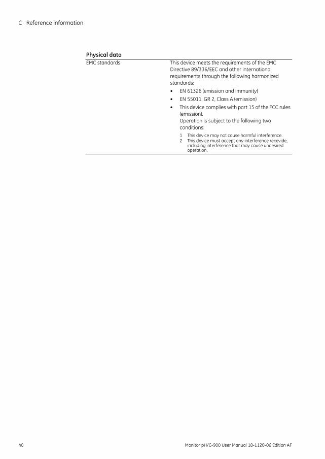
EMC standards This device meets the requirements of the EMC Directive 89/336/EEC and other international requirements through the following harmonized standards:• EN 61326 (emission and immunity)• EN 55011, GR 2, Class A (emission)• This device complies with part 15 of the FCC rules
(emission). Operation is subject to the following two conditions: 1 This device may not cause harmful interference. 2 This device must accept any interference recevide,
including interference that may cause undesired operation.
Physical data
40 Monitor pH/C-900 User Manual 18-1120-06 Edition AF
Reference information D
Monitor pH/C-900 User Manual 18-1120-06 Edition AF 41
D Accessories and spare parts
Item Quantity per pack
Code no.
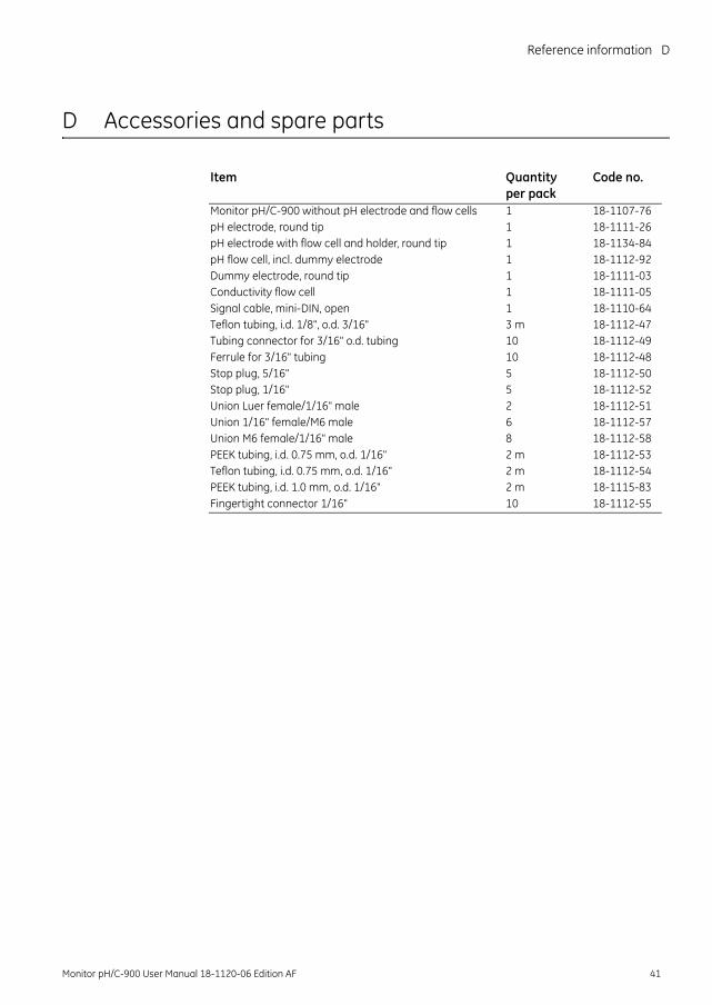
Monitor pH/C-900 without pH electrode and flow cells 1 18-1107-76pH electrode, round tip 1 18-1111-26pH electrode with flow cell and holder, round tip 1 18-1134-84pH flow cell, incl. dummy electrode 1 18-1112-92Dummy electrode, round tip 1 18-1111-03Conductivity flow cell 1 18-1111-05Signal cable, mini-DIN, open 1 18-1110-64Teflon tubing, i.d. 1/8", o.d. 3/16" 3 m 18-1112-47Tubing connector for 3/16" o.d. tubing 10 18-1112-49Ferrule for 3/16" tubing 10 18-1112-48Stop plug, 5/16" 5 18-1112-50Stop plug, 1/16" 5 18-1112-52Union Luer female/1/16" male 2 18-1112-51Union 1/16" female/M6 male 6 18-1112-57Union M6 female/1/16" male 8 18-1112-58PEEK tubing, i.d. 0.75 mm, o.d. 1/16" 2 m 18-1112-53Teflon tubing, i.d. 0.75 mm, o.d. 1/16" 2 m 18-1112-54PEEK tubing, i.d. 1.0 mm, o.d. 1/16" 2 m 18-1115-83Fingertight connector 1/16" 10 18-1112-55
Short instructions
42 Monitor pH/C-900 User Manual 18-1120-06 Edition AF
Short instructions
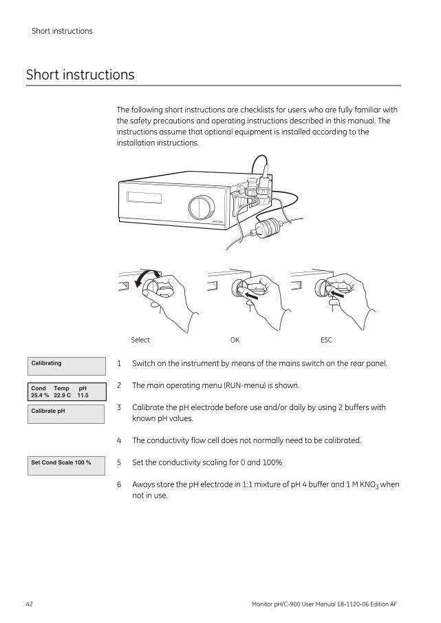
The following short instructions are checklists for users who are fully familiar with the safety precautions and operating instructions described in this manual. The instructions assume that optional equipment is installed according to the installation instructions.
1 Switch on the instrument by means of the mains switch on the rear panel.
2 The main operating menu (RUN-menu) is shown.
3 Calibrate the pH electrode before use and/or daily by using 2 buffers with known pH values.
4 The conductivity flow cell does not normally need to be calibrated.
5 Set the conductivity scaling for 0 and 100%
6 Aways store the pH electrode in 1:1 mixture of pH 4 buffer and 1 M KNO3 when not in use.
pH/C-900
Select OK ESC
Calibrating
Cond Temp pH25.4 % 22.9 C 11.5
Calibrate pH
Set Cond Scale 100 %


For contact information for your local office, please visit www.gelifesciences.com/contact
GE Healthcare Bio-Sciences ABBjörkgatan 30751 84 UppsalaSweden
www.gelifesciences.com
GE imagination at work and GE monogram are trademarks ofGeneral Electric Company.
ÄKTA, Drop Design, ÄKTApurifier, ÄKTAexplorer and UNICORN aretrademarks of GE Healthcare companies.
All third party trademarks are the property of their respective owners.
© 1996–2008 General Electric Company – All rights reserved.First published Sept. 1996.
All goods and services are sold subject to the terms and conditionsof sale of the company within GE Healthcare which supplies them.A copy of these terms and conditions is available on request. Contact your local GE Healthcare representative for the most current information.
GE Healthcare Europe GmbHMunzinger Strasse 5 D-79111 Freiburg Germany
GE Healthcare UK LimitedAmersham PlaceLittle Chalfont Buckinghamshire, HP7 9NA UK
GE Healthcare Bio-Sciences Corp.800 Centennial Avenue, P.O. Box 1327 Piscataway, NJ 08855-1327 USA
GE Healthcare Bio-Sciences KKSanken Bldg. 3-25-1, HyakuninchoShinjuku-ku, Tokyo 169-0073 Japan
imagination at work
18-1120-06AF 06/2008