RUB AND ABRASION TESTER - aticorporation.com
15
©Rhopoint Instruments Ltd. Rhopoint House • Enviro 21 Park • Queensway Avenue South St Leonards on Sea • TN38 9AG UK Web: www.hanatekinstruments.com • Main Office: +44 (0)1424 739 623 OPERATING MANUAL RUB AND ABRASION TESTER
Transcript of RUB AND ABRASION TESTER - aticorporation.com
©Rhopoint Instruments Ltd. Rhopoint House • Enviro 21 Park • Queensway Avenue South
St Leonards on Sea • TN38 9AG UK Web: www.hanatekinstruments.com • Main Office: +44 (0)1424 739 623
OPERATING MANUAL
RUB AND ABRASION TESTER
2
Contents Product Safety ....................................................................................................................................................................... 2 Equipment ............................................................................................................................................................................. 3
Package Contents .............................................................................................................................................................. 3 Optional Extras .................................................................................................................................................................. 4
Operation .............................................................................................................................................................................. 4 Assembly ........................................................................................................................................................................... 4 Powering the instrument .................................................................................................................................................. 4
Set Test Conditions ............................................................................................................................................................... 5 Selecting test conditions ................................................................................................................................................... 5 Turning on/off the fan .................................................................................................................................................... 11
Sample Preparation .............................................................................................................................................................. 5 Sample selection ............................................................................................................................................................... 5 Using the sample templates ............................................................................................................................................. 5
Performing a Test .................................................................................................................................................................. 6 Selecting test type ............................................................................................................................................................. 6 Changing the sample head ................................................................................................................................................ 6 Rubproofness Testing to BS3110 ...................................................................................................................................... 7 Abrasion Testing ............................................................................................................................................................... 9 Wet Rub Testing ................................................................................................................................................................ 9 Selecting test revolutions................................................................................................................................................ 10 Running a test ................................................................................................................................................................. 10 Replacing the pad ........................................................................................................................................................... 11
Test Results ......................................................................................................................................................................... 12 Evaluation of test results ................................................................................................................................................ 12
Service and Repair .............................................................................................................................................................. 13 Calibration ....................................................................................................................................................................... 13 Spares .............................................................................................................................................................................. 13
Certificate of Conformity .................................................................................................................................................... 14 RoHS and WEEE .................................................................................................................................................................. 15
Product Safety
WARNING THE HANATEK RUB TESTER HAS MOVING PARTS WHICH MAY CONSTITUTE A PINCHING RISK FOR HAND/FINGERS AND ENTANGLEMENT RISKS FOR HAIR/CLOTHING. REASONABLE CARE MUST BE TAKEN AT ALL TIMES – DO NOT TOUCH THE MOVING PARTS DURING OPERATION AND ENSURE HAIR AND CLOTHING ARE KEPT CLEAR. THE HANATEK RUB TESTER CONTAINS NO USER SERVICEABLE PARTS. DO NOT OPEN THE INSTRUMENT ENCLOSURE- RISK OF ELECTRIC SHOCK OR FIRE.
Please read this manual before operating the instrument and keep it for future reference RT4: RUB AND ABRASION TESTER MANUAL ISSUE B OCTOBER 2018
3
Equipment
Package Contents
1x Hanatek Rub and Abrasion Tester 3x Mains leads – EU/US/UK
1x Rub Test Sample Template - 115mm 1x DC power pack
1x Rub Test Sample Template - 50mm 1x Knife
1x Test Weight for 1 P.S.I. 1x Manual
1x Standard rub test head 1x Sample clamping ring
1x Test Weight for 2 P.S.I. (when combined with weight 1) 1x Calibration certificate for instrument, templates & weight
1x Bulls eye spirit level 1x Spanner
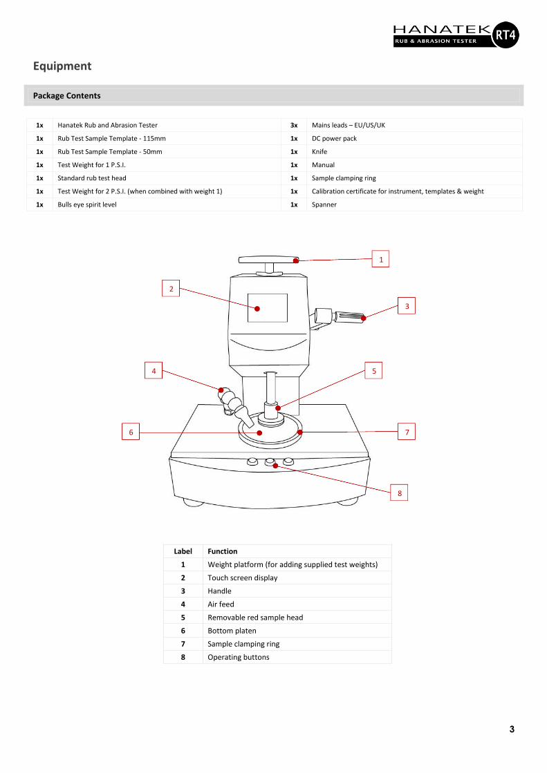
Label Function
1 Weight platform (for adding supplied test weights)
2 Touch screen display
3 Handle
4 Air feed
5 Removable red sample head
6 Bottom platen
7 Sample clamping ring
8 Operating buttons
1
2
9 3
4 5
7 6
8
4
Optional Extras
volume testing. Abrasion Tester Head (HAN-B1002RT4HEAD-S) A more aggressive test, useful for assessing through cure of UV coatings or high abrasion transit testing. Solvent Resistance Test Head (HAN-B1002RT4HEAD-W) Used to test the water, detergent, solvent or fat resistance of inks and coatings.
Operation
Assembly
• Remove the instrument from all packaging. Retain the packaging so that the equipment can be returned for calibration
and service repairs.
• Place the instrument on a suitable bench and put the supplied bull’s eye spirit level on the instrument bed next to the rotating sample holder.
• Check the instrument is level, the bubble should be contained within the circle in the centre of the spirit level. If the weight platform is not level, use the supplied spanner to adjust the feet of the instrument.
Powering the instrument
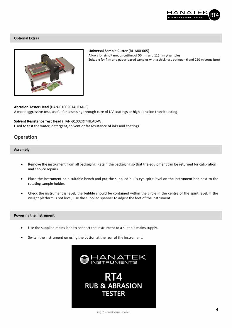
• Use the supplied mains lead to connect the instrument to a suitable mains supply.
• Switch the instrument on using the button at the rear of the instrument.
Universal Sample Cutter (RL-A80-005) Allows for simultaneous cutting of 50mm and 115mm ø samples Suitable for film and paper-based samples with a thickness between 6 and 250 microns (μm)
Fig 1 – Welcome screen
5
Set Test Conditions
Selecting test conditions
Select a test condition that is close to the failure point of the material. Increasing the test pressure increases the severity of the test. The failure point can be found by trial and error, several tests should be carried out using increasing weights until marking of the substrate and/or deterioration of the coating is visible.
Test pressure - The weight set provided allows for 3 test pressures:
Pounds / Inch2 (p.s.i.) kPa Equivalent
Weights
0.5 3.45 None
1.0 6.90 Small
2.0 13.80 Small + Large
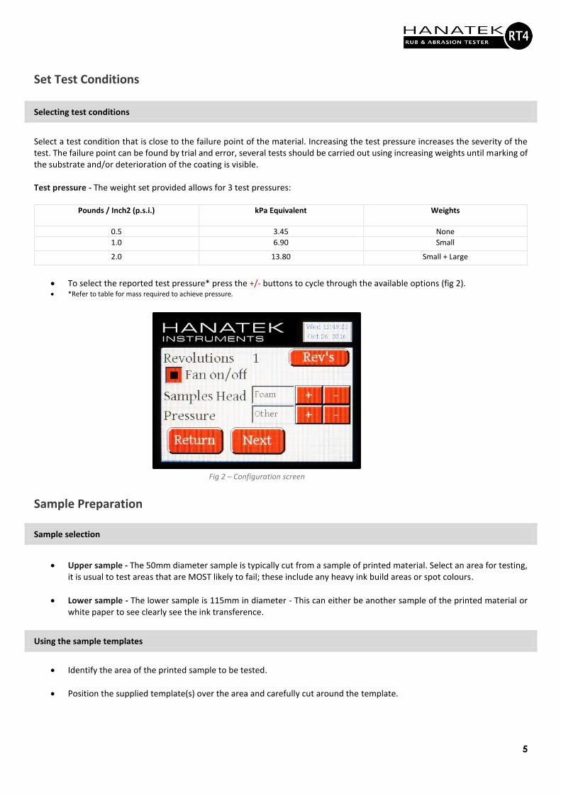
• To select the reported test pressure* press the +/- buttons to cycle through the available options (fig 2). • *Refer to table for mass required to achieve pressure.
Sample Preparation
Sample selection
• Upper sample - The 50mm diameter sample is typically cut from a sample of printed material. Select an area for testing,
it is usual to test areas that are MOST likely to fail; these include any heavy ink build areas or spot colours.
• Lower sample - The lower sample is 115mm in diameter - This can either be another sample of the printed material or white paper to see clearly see the ink transference.
Using the sample templates
• Identify the area of the printed sample to be tested.
• Position the supplied template(s) over the area and carefully cut around the template.
Fig 2 – Configuration screen
6
Performing a Test
Selecting test type
The instrument can be used with three different sample heads. It is supplied with the foam pad as standard. (Abrasion/scratch and felt pad heads are optional extras).
• Foam Pad - used for rubproofness testing for BS3110.
• Abrasion Scratch Test - a more aggressive test, useful for assessing through cure of UV coatings or high abrasion transit testing.
• Felt Pad - used to test the water, detergent, solvent or fat resistance of inks and coatings.
Changing the sample head
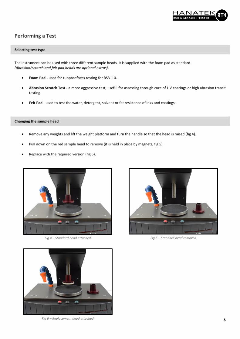
• Remove any weights and lift the weight platform and turn the handle so that the head is raised (fig 4).
• Pull down on the red sample head to remove (it is held in place by magnets, fig 5).
• Replace with the required version (fig 6).
Fig 4 – Standard head attached Fig 5 – Standard head removed
Fig 6 – Replacement head attached
7
Rubproofness Testing to BS3110
Ensure that foam is selected in the test menu and the corresponding sample head is fitted. Test Options
• Face to face - Select an area from the printed material and cut a small and large sample using the sample cutter.
• Face to reference substrate - The large sample should be taken from a sheet of high quality white reference material. The smaller sample is taken from the printed material.
Sample Positioning
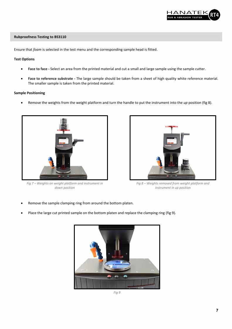
• Remove the weights from the weight platform and turn the handle to put the instrument into the up position (fig 8).
• Remove the sample clamping ring from around the bottom platen.
• Place the large cut printed sample on the bottom platen and replace the clamping ring (fig 9).
Fig 7 – Weights on weight platform and instrument in down position
Fig 8 – Weights removed from weight platform and instrument in up position
Fig 9
8
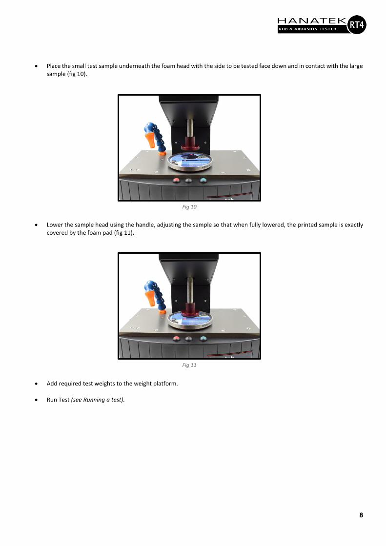
• Place the small test sample underneath the foam head with the side to be tested face down and in contact with the large sample (fig 10).
• Lower the sample head using the handle, adjusting the sample so that when fully lowered, the printed sample is exactly covered by the foam pad (fig 11).
• Add required test weights to the weight platform.
• Run Test (see Running a test).
Fig 10
Fig 11
9
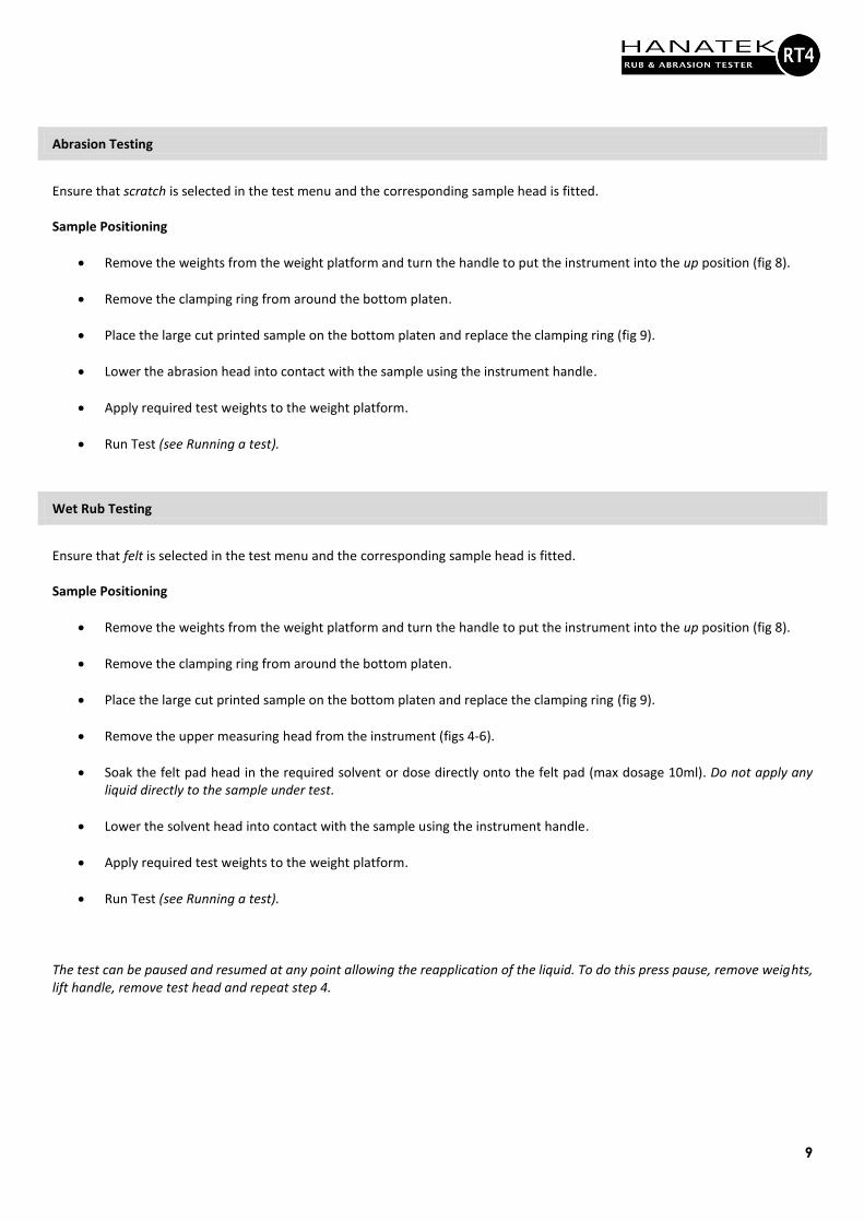
Abrasion Testing
Ensure that scratch is selected in the test menu and the corresponding sample head is fitted. Sample Positioning
• Remove the weights from the weight platform and turn the handle to put the instrument into the up position (fig 8).
• Remove the clamping ring from around the bottom platen.
• Place the large cut printed sample on the bottom platen and replace the clamping ring (fig 9).
• Lower the abrasion head into contact with the sample using the instrument handle.
• Apply required test weights to the weight platform.
• Run Test (see Running a test).
Wet Rub Testing
Ensure that felt is selected in the test menu and the corresponding sample head is fitted.
Sample Positioning
• Remove the weights from the weight platform and turn the handle to put the instrument into the up position (fig 8).
• Remove the clamping ring from around the bottom platen.
• Place the large cut printed sample on the bottom platen and replace the clamping ring (fig 9).
• Remove the upper measuring head from the instrument (figs 4-6).
• Soak the felt pad head in the required solvent or dose directly onto the felt pad (max dosage 10ml). Do not apply any liquid directly to the sample under test.
• Lower the solvent head into contact with the sample using the instrument handle.
• Apply required test weights to the weight platform.
• Run Test (see Running a test).
The test can be paused and resumed at any point allowing the reapplication of the liquid. To do this press pause, remove weights, lift handle, remove test head and repeat step 4.
10
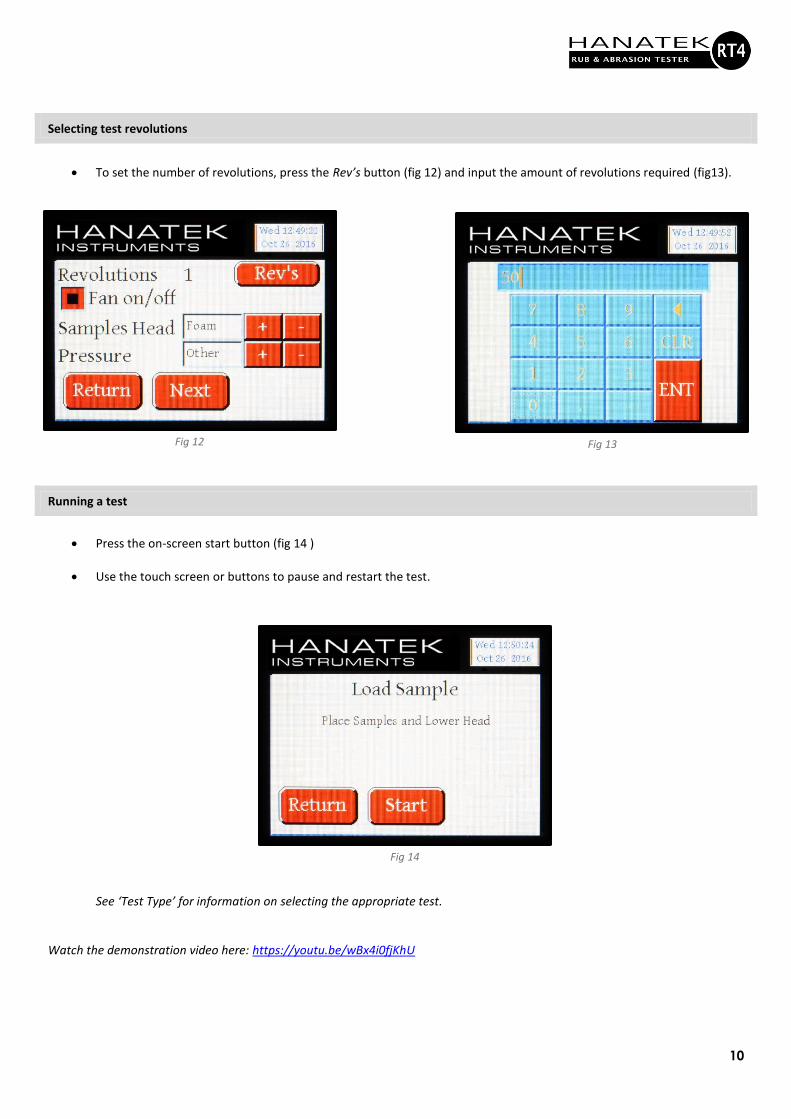
Selecting test revolutions
• To set the number of revolutions, press the Rev’s button (fig 12) and input the amount of revolutions required (fig13).
Running a test
• Press the on-screen start button (fig 14 )
• Use the touch screen or buttons to pause and restart the test. See ‘Test Type’ for information on selecting the appropriate test.
Watch the demonstration video here: https://youtu.be/wBx4i0fjKhU
Fig 14
Fig 12 Fig 13
11
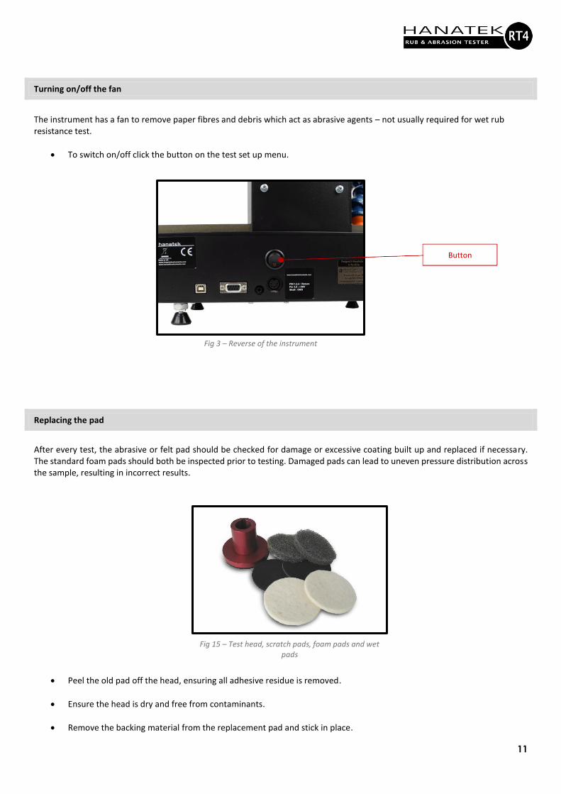
Turning on/off the fan
The instrument has a fan to remove paper fibres and debris which act as abrasive agents – not usually required for wet rub resistance test.
• To switch on/off click the button on the test set up menu.
Replacing the pad
After every test, the abrasive or felt pad should be checked for damage or excessive coating built up and replaced if necessary. The standard foam pads should both be inspected prior to testing. Damaged pads can lead to uneven pressure distribution across the sample, resulting in incorrect results.
• Peel the old pad off the head, ensuring all adhesive residue is removed.
• Ensure the head is dry and free from contaminants.
• Remove the backing material from the replacement pad and stick in place.
Fig 15 – Test head, scratch pads, foam pads and wet pads
Button
Fig 3 – Reverse of the instrument

12
Test Results
Evaluation of test results
Pass/fail of each test is determined visually or by further analysis by using a densitometer, glossmeter or spectrophotometer.
13
Service and Repair
Calibration
To maintain the optimum performance of this machine Hanatek Instruments recommends an annual recalibration of the equipment. A full list of service centres can be found on the Hanatek website: https://www.hanatekinstruments.com/support/authorised-service-centres/
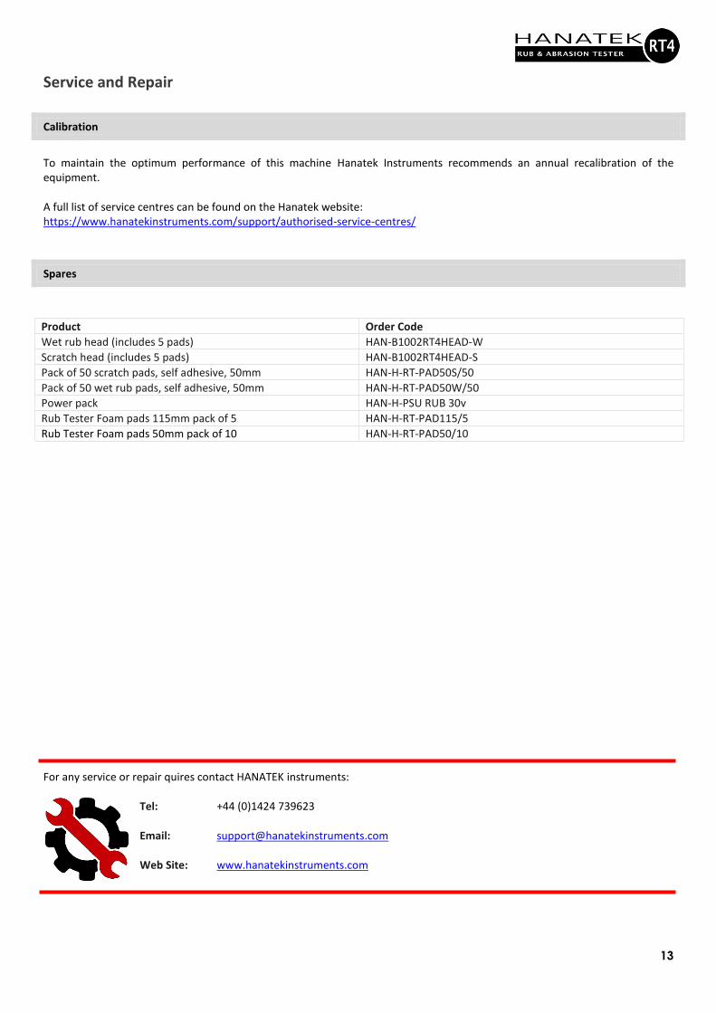
Spares
Product Order Code
Wet rub head (includes 5 pads) HAN-B1002RT4HEAD-W
Scratch head (includes 5 pads) HAN-B1002RT4HEAD-S
Pack of 50 scratch pads, self adhesive, 50mm HAN-H-RT-PAD50S/50
Pack of 50 wet rub pads, self adhesive, 50mm HAN-H-RT-PAD50W/50
Power pack HAN-H-PSU RUB 30v
Rub Tester Foam pads 115mm pack of 5 HAN-H-RT-PAD115/5
Rub Tester Foam pads 50mm pack of 10 HAN-H-RT-PAD50/10
For any service or repair quires contact HANATEK instruments:
Tel: +44 (0)1424 739623 Email: [email protected] Web Site: www.hanatekinstruments.com

14
Certificate of Conformity
15
RoHS and WEEE
EU Directive 2002/96/EC on WEEE (Waste Electrical & Electronic Equipment) and RoHS (Restriction of the use of certain
Hazardous Substances).
The European Union's Directive on Restriction of the use of certain Hazardous Substances in electrical and electronic equipment (ROHS) defines each of 10 categories of electrical and electronic equipment in Annex I . Category 9 is defined as follows: 9. Monitoring and control instruments
Smoke detector
Heating regulators
Thermostats
Measuring, weighing, or adjusting appliances for household or as laboratory equipment
Other monitoring and control instruments used in industrial installations (e.g. in control panels).
The RoHS Directive defines the scope of restrictions in Article 2 as follows:
"1. Without prejudice to Article 6, this Directive shall apply to electrical and electronic equipment falling under the
categories I, 2, 3, 4, 5, 6, 7 and 10 set out in Annex IA to Directive No 2002/96/EC (WEEE) and to electric light bulbs,
and luminaires in households."
This product is supplied as a Monitoring and Control instrument and as such falls within category 9 of the EU directive
2002/96/EC and so is excluded from restrictions under the scope of the RoHS Directive.
The Waste Electrical and Electronic Equipment Directive is intended to reduce the amount of harmful substances that
are added to the environment by the inappropriate disposal of these products through municipal waste.
Some of the materials contained in electrical and electronic products can damage the environment and are potentially
hazardous to human health; for this reason, the products are marked with the crossed-out wheelie bin symbol which
indicates that they must not he disposed of via unsorted municipal waste.
Rhopoint Instruments Ltd have arranged a means for our customers to have products that have reached the end of
their useful life safely recycled. We encourage all end users to us at the end of the product's life to return their
purchase to as for recycling as per Article 9 of the WEEE Directive.
Please contact us on +44 (0) 1424-739622 and we will advise on the process for returning these waste products so we
can all contribute to the safe recycling of these materials.