RTV 900 Install - Wiedmann Bros · Southwest AG, Inc. Kubota RTV 900 Kit Parts List (1)...
14
INSTALLATION INSTRUCTIONS TURBOCHARGER SYSTEM: Kubota RTV 900 Southwest AG, Inc. - 39927 US Hwy. 160 Bayfield CO 81122 Ph: 970.884.4101 - Fax: 970.884.9228 - Toll Free Phone: 800.218.2347
Transcript of RTV 900 Install - Wiedmann Bros · Southwest AG, Inc. Kubota RTV 900 Kit Parts List (1)...

INSTALLATION INSTRUCTIONS
TURBOCHARGER SYSTEM: Kubota RTV 900
Southwest AG, Inc. - 39927 US Hwy. 160 Bayfield CO 81122 Ph: 970.884.4101 - Fax: 970.884.9228 - Toll Free Phone: 800.218.2347

Southwest AG, Inc. Kubota RTV 900 Kit Parts List
(1) Turbocharger
(1) Turbo Adapter (1) Exhaust Pipe #1
(1) Exhaust Pipe #2
(1) Exhaust Pipe #3 (2) Exhaust Clamps
(1) Exhaust Hanger
(1) Charge Pipe #1 (1) Charge Pipe #2
(1) Intake Pipe
(6) T-Bolt Clamps (Lg) (1) T-Bolt Clamp (Sm)
(1) Reducer Coupler
(1) Straight Coupler (Short) (1) Straight Coupler (Long)

(2) M6x20 Bolts & Washers
(4) M8x20 Bolts & Washers (2) M8 Nuts & Washers
(1) Oil Feed Line
(1) Oil Feed Tee (1) Oil Feed Fitting (Block)
(1) Oil Feed Fitting (Turbo)
(1) Oil Drain Flange (Turbo) (1) Oil Drain Line
(1) Oil Pan Fitting
(2) Oil Drain Line Clamps (2) M6x16 Bolts & Washers
(1) Breather Cap

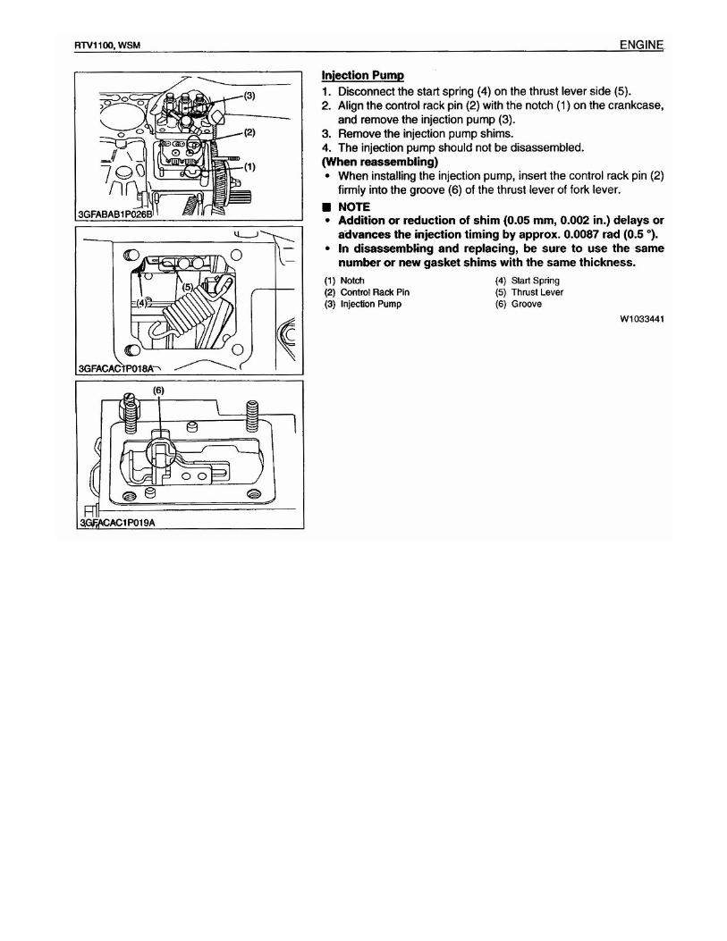
Fuel Injector Pump Modification Remove injector lines and fuel inlet and return lines from pump, them remove pump from Engine block. Once pump is removed locate the thinnest shim and remove (do not reuse). Now set the pump fuel delivery to max full per drawing below. Reinstall pump be careful to line up the rack pin on back of pump with the slot on rack in the block.

* Remove the ONE shim with the MOST Small holes
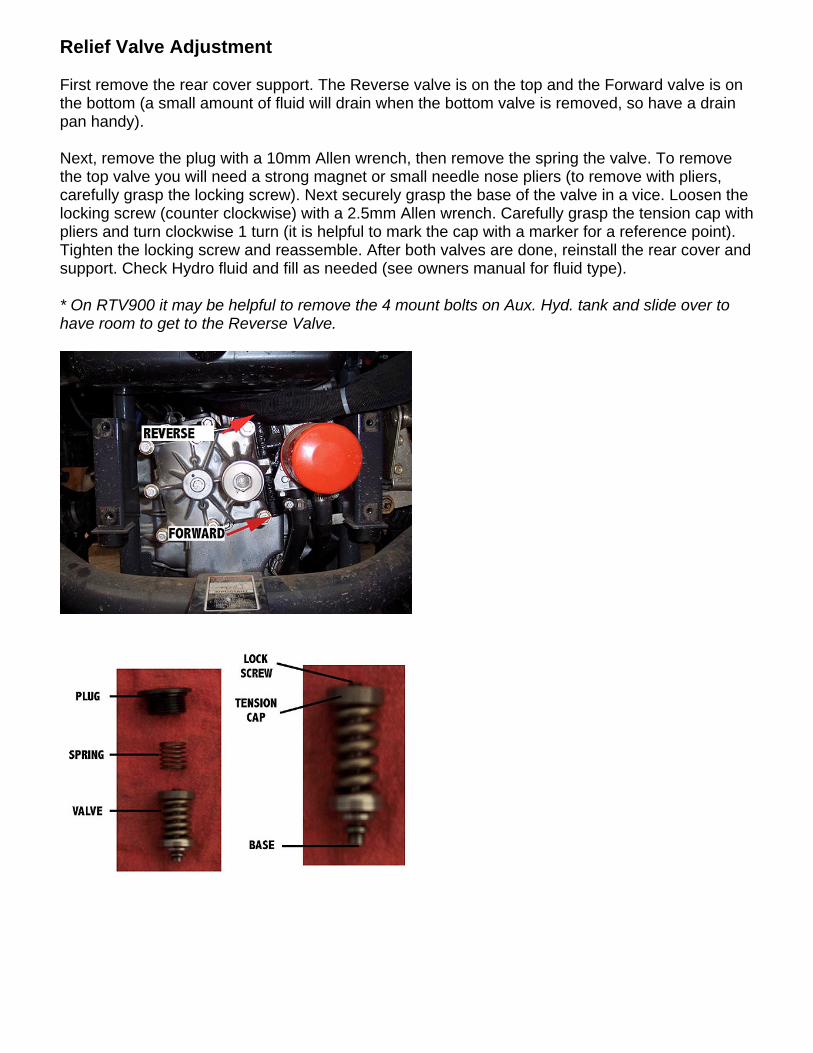
Relief Valve Adjustment First remove the rear cover support. The Reverse valve is on the top and the Forward valve is on the bottom (a small amount of fluid will drain when the bottom valve is removed, so have a drain pan handy). Next, remove the plug with a 10mm Allen wrench, then remove the spring the valve. To remove the top valve you will need a strong magnet or small needle nose pliers (to remove with pliers, carefully grasp the locking screw). Next securely grasp the base of the valve in a vice. Loosen the locking screw (counter clockwise) with a 2.5mm Allen wrench. Carefully grasp the tension cap with pliers and turn clockwise 1 turn (it is helpful to mark the cap with a marker for a reference point). Tighten the locking screw and reassemble. After both valves are done, reinstall the rear cover and support. Check Hydro fluid and fill as needed (see owners manual for fluid type). * On RTV900 it may be helpful to remove the 4 mount bolts on Aux. Hyd. tank and slide over to have room to get to the Reverse Valve.
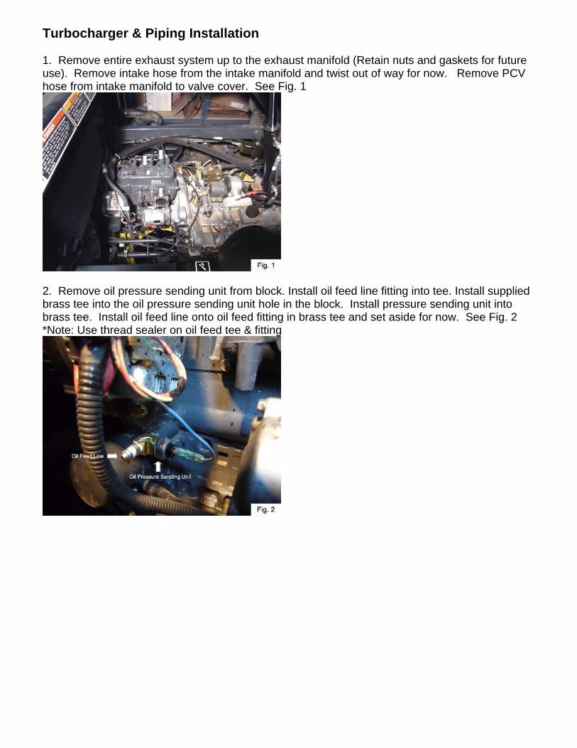
Turbocharger & Piping Installation 1. Remove entire exhaust system up to the exhaust manifold (Retain nuts and gaskets for future use). Remove intake hose from the intake manifold and twist out of way for now. Remove PCV hose from intake manifold to valve cover. See Fig. 1
2. Remove oil pressure sending unit from block. Install oil feed line fitting into tee. Install supplied brass tee into the oil pressure sending unit hole in the block. Install pressure sending unit into brass tee. Install oil feed line onto oil feed fitting in brass tee and set aside for now. See Fig. 2 *Note: Use thread sealer on oil feed tee & fitting

3. Drill oil pan and install brass barb fitting for oil return right at the 4th pan bolt. (older RTV 900 use alternate location to clear motormount) Use a 9/16 drill bit and 3/8 NPT tap. Only tap into the pan a short amount – do NOT feed tap all the way into the pan as the hole will be too big to seal properly. Rotate brass barb so that the oil drain tube is pointing upwards. See Fig 3 & 4, Diagram 1 Note: Mark the drain flange to show where the top of the tube is will help locating the top while tightening.
• Use Permatex High Temp Thread Sealant or Equivalent on threads

4. Install turbo adapter to exhaust manifold using factory nuts and gasket. See Fig. 9 & 10
5. Install oil feed fitting on turbo using supplied crush washer. Install oil return flange & gasket on turbo using M6 bolts & Bellevue Washers. See Fig. 11 & 12
6. Install downpipe & gasket on turbo. Install oil return line onto fitting on oil pan and connect to turbo BEFORE bolting turbo up. See Fig. 13 & 14
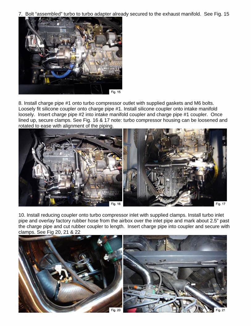
7. Bolt “assembled” turbo to turbo adapter already secured to the exhaust manifold. See Fig. 15
8. Install charge pipe #1 onto turbo compressor outlet with supplied gaskets and M6 bolts. Loosely fit silicone coupler onto charge pipe #1. Install silicone coupler onto intake manifold loosely. Insert charge pipe #2 into intake manifold coupler and charge pipe #1 coupler. Once lined up, secure clamps. See Fig. 16 & 17 note: turbo compressor housing can be loosened and rotated to ease with alignment of the piping.
10. Install reducing coupler onto turbo compressor inlet with supplied clamps. Install turbo inlet pipe and overlay factory rubber hose from the airbox over the inlet pipe and mark about 2.5” past the charge pipe and cut rubber coupler to length. Insert charge pipe into coupler and secure with clamps. See Fig 20, 21 & 22
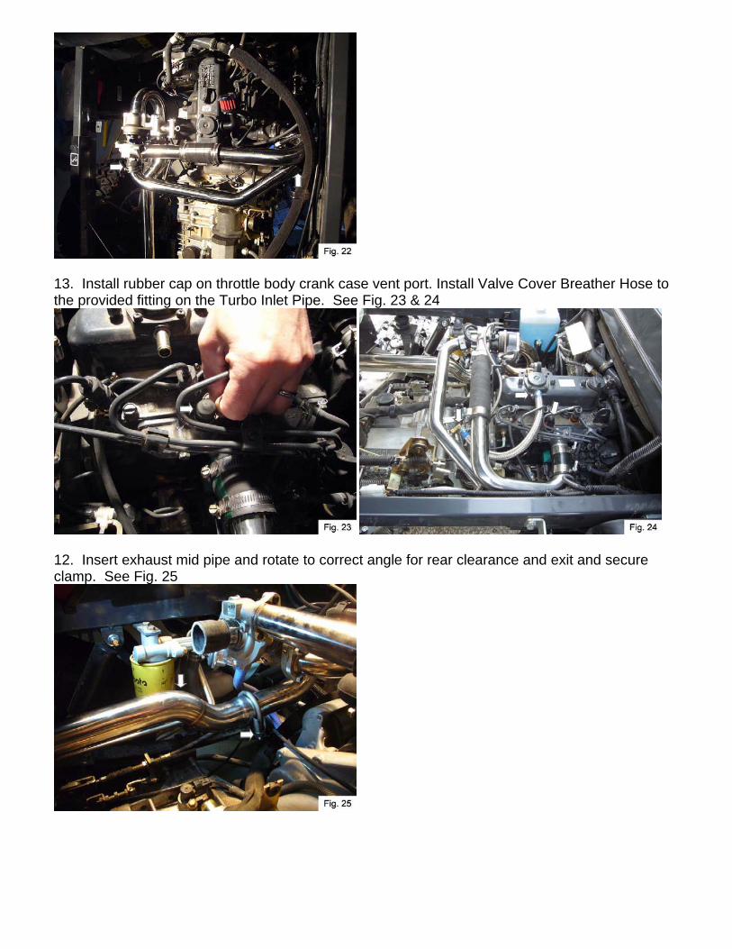
13. Install rubber cap on throttle body crank case vent port. Install Valve Cover Breather Hose to the provided fitting on the Turbo Inlet Pipe. See Fig. 23 & 24
12. Insert exhaust mid pipe and rotate to correct angle for rear clearance and exit and secure clamp. See Fig. 25

13. Install last section of exhaust pipe and clamp and secure. Secure the rear section of exhaust on this clamp with supplied universal exhaust hanger. See Fig. 26 & 27

Turbo Boost Adjustment If a boost gauge is to be installed do so at this time. Mount the gauge to the dash and carefully route tube from gauge to turbo. (Drill small hole in dash and feed tube from gauge into dash, behind instrument panel, down underneath with wire harness and up to turbo attaching tube carefully with wire ties to harness). Remove boost line from Turbo and replace with 3/16" fuel line and hose clamps. Install tee in new boost line and attach tube from gauge. * *If boost gauge is not permanently installed, install temporary gauge into boost line.
Loosen lock nut on turbo. Start vehicle & warm up long enough for the temp gauge to rise slightly. To increase boost adjustment knob so the rod is shortened. At idle, increase boost until the turbo whistles (it may be necessary to bump the throttle from time to time).
Adjust until 5-7 PSI of boost is achieved under load such as driving uphill. Tighten lock nut on turbo (if temporary gauge is used, remove and install 3/16" fuel line with hose clamps to turbo as the boost line). * It may be necessary to readjust boost at a later time due to the controller bracket movement. If a loss of power is noticed, readjust boost using the above instructions.