RSE INSTALLATION INSTRUCTIONS - …downloads.chiefmfg.com/MANUALS-I/RSE-I.pdf · RSE Installation...
38
INSTALLATION INSTRUCTIONS INSTRUCTIONS D'INSTALLATION MONTAGEANLEITUNG RSE RSE Projector Mounts Supports pour projecteur RSE RSE-Projektorhalterungen
Transcript of RSE INSTALLATION INSTRUCTIONS - …downloads.chiefmfg.com/MANUALS-I/RSE-I.pdf · RSE Installation...

I N S T A L L A T I O N I N S T R U C T I O N SI N S T R U C T I O N S D ' I N S T A L L A T I O N
M O N T A G E A N L E I T U N G
RSE
RSE Projector MountsSupports pour projecteur RSE
RSE-Projektorhalterungen

RSE Installation Instructions
2
DISCLAIMERMilestone AV Technologies, and its affiliated corporations andsubsidiaries (collectively, “Milestone”), intend to make thismanual accurate and complete. However, Milestone makes noclaim that the information contained herein covers all details,conditions or variations, nor does it provide for every possiblecontingency in connection with the installation or use of thisproduct. The information contained in this document is subjectto change without notice or obligation of any kind. Milestonemakes no representation of warranty, expressed or implied,regarding the information contained herein. Milestone assumesno responsibility for accuracy, completeness or sufficiency ofthe information contained in this document.
Chief® is a registered trademark of Milestone AV Technologies.All rights reserved.
IMPORTANT SAFETY INSTRUCTIONS!
WARNING: A WARNING alerts you to the possibility ofserious injury or death if you do not follow the instructions.
CAUTION: A CAUTION alerts you to the possibility ofdamage or destruction of equipment if you do not follow thecorresponding instructions.
WARNING: Failure to read, thoroughly understand, andfollow all instructions can result in serious personal injury,damage to equipment, or voiding of factory warranty! It is theinstaller’s responsibility to make sure all components areproperly assembled and installed using the instructionsprovided.
WARNING: Failure to provide adequate structural strengthfor this component can result in serious personal injury ordamage to equipment! It is the installer’s responsibility tomake sure the structure to which this component is attached
can support five times the combined weight of all equipment.Reinforce the structure as required before installing thecomponent.
WARNING: Exceeding the weight capacity can result inserious personal injury or damage to equipment! It is theinstaller’s responsibility to make sure the combined weight ofall components attached to the RSE does not exceed 25 lbs(11.37 kg).
• The weight capacity of the RSE may be LIMITED to thelowest weight capacity of any other componentslocated between the RSE and the supporting structure!
WARNING: Use this mounting system only for its intendeduse as described in these instructions. Do not useattachments not recommended by the manufacturer.
WARNING: Never operate this mounting system if it isdamaged. Return the mounting system to a service center forexamination and repair.
WARNING: Do not use this product outdoors.
IMPORTANT ! : The RSE mounts are designed to be:• mounted to a 1-1/2” NPT or NPSM steel or aluminum
threaded extension column; or• mounted to double 2" x 4" wood stud cross bracing
(1-1/2” on center) between two 2" x 4" ceiling joists;• mounted to a concrete ceiling with a minimum
thickness of 8" and a maximum drywall covering of5/8”; or
• suspended from four #10-24 diameter (minimum)threaded rods (not included) which are secured tounistrut, angle or channel assembly overheadstructural members (trusses or I-beams) by #10channel nuts (not included).--SAVE THESE INSTRUCTIONS--
DIMENSIONS
1.4436.6
ROLLADJUSTMENT POINT
4
4.38111.1
1.4436.5
3.1078.8
25

Installation Instructions RSE
3
LEGENDTighten Fastener
Serrez les fixations
Serrare il fissaggio
Befestigungsteil festziehen
Apretar elemento de fijación
Bevestiging vastdraaien
Apertar fixador
Loosen Fastener
Desserrez les fixations
Allentare il fissaggio
Befestigungsteil lösen
Aflojar elemento de fijación
Bevestiging losdraaien
Desapertar fixador
Phillips Screwdriver
Tournevis à pointe cruciforme
Cacciavite a stella
Kreuzschlitzschraubendreher
Destornillador Phillips
Kruiskopschroevendraaier
Chave de fendas Phillips
Hex-Head Wrench
Clé à tête hexagonale
Chiave esagonale
Sechskantschlüssel
Llave de cabeza hexagonal
Zeskantsleutel
Chave de cabeça sextavada
Open-Ended Wrench
Clé à fourche
Chiave a punte aperte
Gabelschlüssel
Llave de boca
Steeksleutel
Chave de bocas
By Hand
À la main
A mano
Von Hand
A mano
Met de hand
Com a mão
Pencil Mark
Marquage au crayon
Segno a matita
Stiftmarkierung
Marcar con lápiz
Potloodmerkteken
Marcar com lápis
Drill Hole
Percez un trou
Praticare un foro
Bohrloch
Perforar
Gat boren
Fazer furo
Adjust
Ajuster
Regolare
Einstellen
Ajustar
Afstellen
Ajustar
Remove
Retirez
Rimuovere
Entfernen
Quitar
Verwijderen
Remover
Optional
En option
Opzionale
Optional
Opcional
Optie
Opcional
Security Wrench
Clé de sécurité
Chiave di sicurezza
Sicherheitsschlüssel
Llave de seguridad
Veiligheidssleutel
Chave de segurança

RSE Installation Instructions
4
TOOLS REQUIRED FOR INSTALLATION
PARTS
Hammer
Martillo
Hammer
Martelo
Martello
Hamer
Marteau
Target of Projector
Punto de enfoque del proyector
Ziel des Projektors
Mira do projector
Punto di proiezione
Doel van de projector
Cible du projecteur
7/16"
3/32" (wood)1/4" (concrete)
#2
Hardware required - not included(dependent on installation method)
1. Install to threaded extension column• 1-1/2" NPT or NPSM steel or aluminum threaded
extension column rated for 50 lbs or greater2. Install to wood ceiling joists
• #10 x 3" Phillips head wood screws (Qty. 4)• #10 washers (Qty. 4)
3. Install to concrete
• 3/8" x 2-1/4" Grade 2 concrete anchors (Qty. 4)• #10 washers (Qty. 4)• #10 x 3" Phillips head wood screws (Qty. 4)
4. Install to threaded rod
• #10-24 steel threaded rods (Qty. 4)• #10-24 channel nuts (Qty. 4)• #10-24 jam nuts (Qty. 8)• #10 washers (Qty. 8)
M6 (included)
All-PointsSecurityKit (Optional)
A (1)
on projector model)
Example Only(Interface bracketvaries dependent
B (1)
[RSE]
C (2)M16x6mm
D (2)M16x6mm (security)
G (1)M6
E (2)M6
F (2)M6
Installation Instructions RSE
5
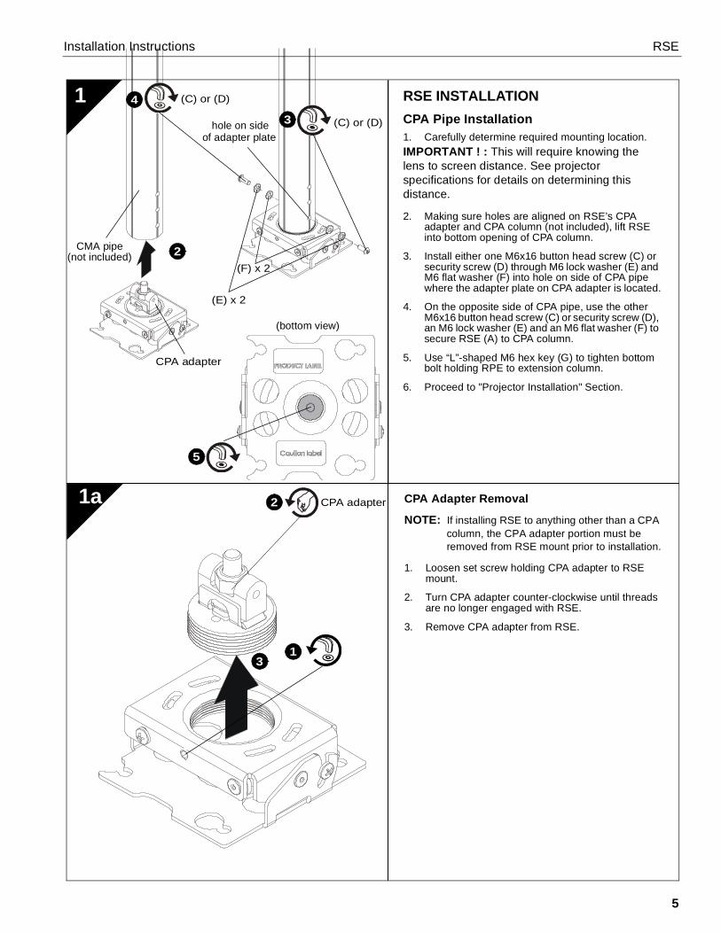
CPA Adapter Removal
NOTE: If installing RSE to anything other than a CPAcolumn, the CPA adapter portion must beremoved from RSE mount prior to installation.
1. Loosen set screw holding CPA adapter to RSEmount.
2. Turn CPA adapter counter-clockwise until threadsare no longer engaged with RSE.
3. Remove CPA adapter from RSE.
RSE INSTALLATIONCPA Pipe Installation1. Carefully determine required mounting location.IMPORTANT ! : This will require knowing thelens to screen distance. See projectorspecifications for details on determining thisdistance.
2. Making sure holes are aligned on RSE’s CPAadapter and CPA column (not included), lift RSEinto bottom opening of CPA column.
3. Install either one M6x16 button head screw (C) orsecurity screw (D) through M6 lock washer (E) andM6 flat washer (F) into hole on side of CPA pipewhere the adapter plate on CPA adapter is located.
4. On the opposite side of CPA pipe, use the otherM6x16 button head screw (C) or security screw (D),an M6 lock washer (E) and an M6 flat washer (F) tosecure RSE (A) to CPA column.
5. Use “L”-shaped M6 hex key (G) to tighten bottombolt holding RPE to extension column.
6. Proceed to "Projector Installation" Section.
1a
13
2CMA pipe(not included)
4
(C) or (D)
(C) or (D)
CPA adapter
hole on sideof adapter plate
2
31
CPA adapter
(bottom view)
5
(F) x 2
(E) x 2

RSE Installation Instructions
6
(A)
1
2
4
2
(A)
3
RSE INSTALLATIONThreaded Pipe InstallationNOTE: CPA adapter must be removed prior to
installing RSE to threaded pipe. See Section1a for details.
1. Carefully determine required mounting location.IMPORTANT ! : This will require knowing thelens to screen distance. See projectorspecifications for details on determining thisdistance.
2. Install 1-1/2" NPT or NPSM steel or aluminumthreaded extension column (not included) intothreaded collar until tight, with a minimum of fourthreads engaged.
WARNING: IMPROPER INSTALLATION CANRESULT IN SERIOUS PERSONAL INJURY ORDAMAGE TO EQUIPMENT! Structural membersMUST be capable of supporting five times thecombined weight of all equipment being mounted.
3. Align RSE with end of NPT pipe.
4. Thread RSE up onto pipe by turning counter-clockwise until hand tight.
Rough Alignment of RSE
1. Turn RSE clockwise or counter-clockwise until frontof mount is facing target.
IMPORTANT ! : When RSE is properlypositioned, the set screw access hole should bepointing directly at target.(see bottom detail in figure at left)
2. Secure RSE to pipe by turning set screw with a5/32" hex key until tight.
CAUTION: DO NOT OVERTIGHTEN!Overtightening of set screw can damage threads onpipe.
1b
1
(not included)
(not included)

Installation Instructions RSE
7
INSTALLATION
1c Wood Stud InstallationNOTE: CPA adapter must be removed prior to
installing RSE to wood studs. See Section 1afor details.
1. Carefully determine required mounting location.
IMPORTANT ! : This will require knowing the lensto screen distance. See projector specifications fordetails on determining this distance.
WARNING: IMPROPER INSTALLATION CANRESULT IN SERIOUS PERSONAL INJURY ORDAMAGE TO EQUIPMENT! Structural membersMUST be capable of supporting five times thecombined weight of all equipment being mounted.
IMPORTANT ! : The RSE mounts are designed to bemounted to double 2" x 4" wood stud cross bracing(1-1/2" on center) between two ceiling joists.
2. Using the RSE as a guide, mark four mounting holelocations with a pencil or similar tool. Hole locationsmust be centered on 2" x 4" cross braces.
3. Drill four 3/32" (2.5mm) dia. pilot holes to a depth of1-3/4" (45mm) deep.
4. Align four mounting holes in RSE with four pilotholes.
IMPORTANT ! : Make sure mount is properlyoriented towards target before securing tostructure.
5. Secure RSE to structure using four #10 flat washersand four #10 x 3" Phillips head wood screws (notincluded).
X4
X4
3
1
2
4
Ø 2.5mm(Ø 3/32”)
45mm(1-3/4”)
5
(A)
x 4
RSE Installation Instructions
8
1d
Ø 6.3mm(Ø 1/4”)
64mm(2-1/2”)
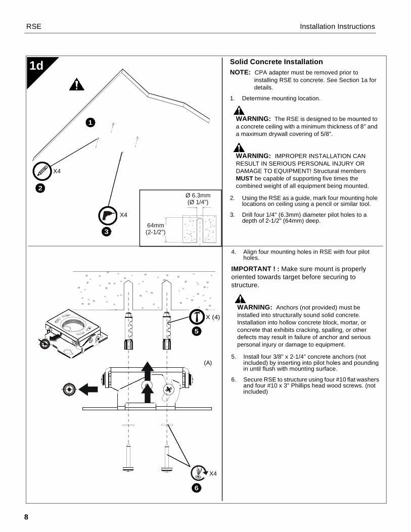
Solid Concrete InstallationNOTE: CPA adapter must be removed prior to
installing RSE to concrete. See Section 1a fordetails.
1. Determine mounting location.
WARNING: The RSE is designed to be mounted toa concrete ceiling with a minimum thickness of 8" anda maximum drywall covering of 5/8".
WARNING: IMPROPER INSTALLATION CANRESULT IN SERIOUS PERSONAL INJURY ORDAMAGE TO EQUIPMENT! Structural membersMUST be capable of supporting five times thecombined weight of all equipment being mounted.
2. Using the RSE as a guide, mark four mounting holelocations on ceiling using a pencil or similar tool.
3. Drill four 1/4" (6.3mm) diameter pilot holes to adepth of 2-1/2" (64mm) deep.
4. Align four mounting holes in RSE with four pilotholes.
IMPORTANT ! : Make sure mount is properlyoriented towards target before securing tostructure.
WARNING: Anchors (not provided) must beinstalled into structurally sound solid concrete.Installation into hollow concrete block, mortar, orconcrete that exhibits cracking, spalling, or otherdefects may result in failure of anchor and seriouspersonal injury or damage to equipment.
5. Install four 3/8" x 2-1/4" concrete anchors (notincluded) by inserting into pilot holes and poundingin until flush with mounting surface.
6. Secure RSE to structure using four #10 flat washersand four #10 x 3" Phillips head wood screws. (notincluded)
3
X4
X4
1
2
(A)
5
X4
6
X (4)

Installation Instructions RSE
9
Ø 2.5mm(Ø 3/32”)
45mm(1-3/4”)
PROJECTOR INSTALLATIONIMPORTANT ! : Model RSE uses optional Chief"SSB" Series interface brackets. (See Partsdrawing.)
Install Interface Bracket1. Partially thread thumb nuts onto Phillips screws until
screw end is visible in top of thumb screw.
IMPORTANT ! : DO NOT fully tighten thumbscrews at this time.
Threaded Rod InstallationNOTE: CPA adapter must be removed prior to
installing RSME to threaded rods. See Section1a for details.
The RSE must be suspended from four #10-24diameter (minimum) threaded rods (not included) whichare secured to unistrut, angle or channel assemblyoverhead structural members (trusses or I-beams) by#10-24 channel nuts (not included).
WARNING: IMPROPER INSTALLATION CANRESULT IN SERIOUS PERSONAL INJURY ORDAMAGE TO EQUIPMENT! Structural membersMUST be capable of supporting five times thecombined weight of all equipment being mounted.
1. Carefully determine required mount position.IMPORTANT ! : This will require knowing the lensto screen distance. See projector specificationsfor determining this distance.
NOTE: Threaded rod and installation hardware notincluded.
2. Secure one end of the threaded rod to the structuralmember.
3. Install four #10-24 jam nuts on each threaded rod.
4. Install the RSE on the threaded rod.
NOTE: Hole in the RSE allows socket wrench accesswithout unit disassembly.
5. Secure the RSE to the threaded rod using four #10channel nuts.
2
1e
Example Only(Interface bracketvaries dependenton projector model)
2
2
(A)
1 2
4
X 45
RSE Installation Instructions
10
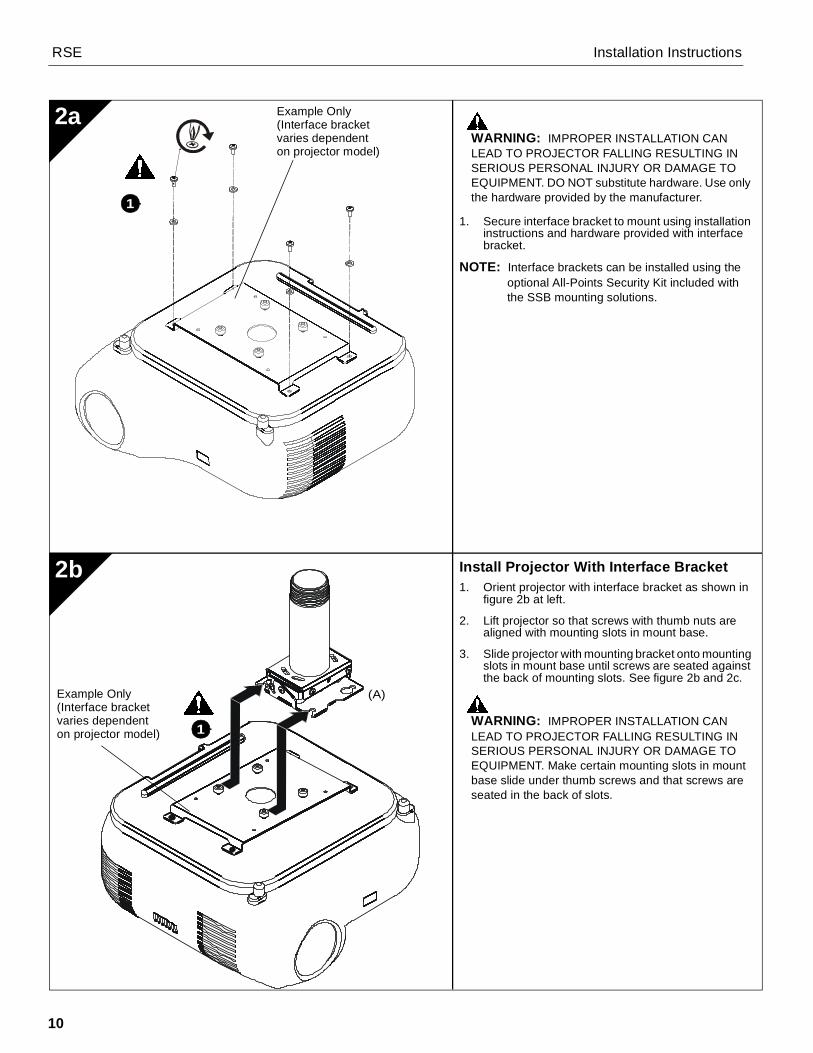
Install Projector With Interface Bracket1. Orient projector with interface bracket as shown in
figure 2b at left.
2. Lift projector so that screws with thumb nuts arealigned with mounting slots in mount base.
3. Slide projector with mounting bracket onto mountingslots in mount base until screws are seated againstthe back of mounting slots. See figure 2b and 2c.
WARNING: IMPROPER INSTALLATION CANLEAD TO PROJECTOR FALLING RESULTING INSERIOUS PERSONAL INJURY OR DAMAGE TOEQUIPMENT. Make certain mounting slots in mountbase slide under thumb screws and that screws areseated in the back of slots.
WARNING: IMPROPER INSTALLATION CANLEAD TO PROJECTOR FALLING RESULTING INSERIOUS PERSONAL INJURY OR DAMAGE TOEQUIPMENT. DO NOT substitute hardware. Use onlythe hardware provided by the manufacturer.
1. Secure interface bracket to mount using installationinstructions and hardware provided with interfacebracket.
NOTE: Interface brackets can be installed using theoptional All-Points Security Kit included withthe SSB mounting solutions.
2b
2a
(A)
1
1
Example Only(Interface bracketvaries dependenton projector model)
Example Only(Interface bracketvaries dependenton projector model)

Installation Instructions RSE
11
Securing Projector with Interface Bracketto Model RSE Mount
WARNING: IMPROPER INSTALLATION CANLEAD TO PROJECTOR FALLING RESULTING INSERIOUS PERSONAL INJURY OR DAMAGE TOEQUIPMENT. Make certain mounting slots in mountbase slide under thumb screws and that screws areseated in the back of slots.
1. Turn thumb nuts until tight to secure projector tomount.
2c
1 X 4
Example Only(Interface bracketvaries dependenton projector model)

RSE Installation Instructions
12
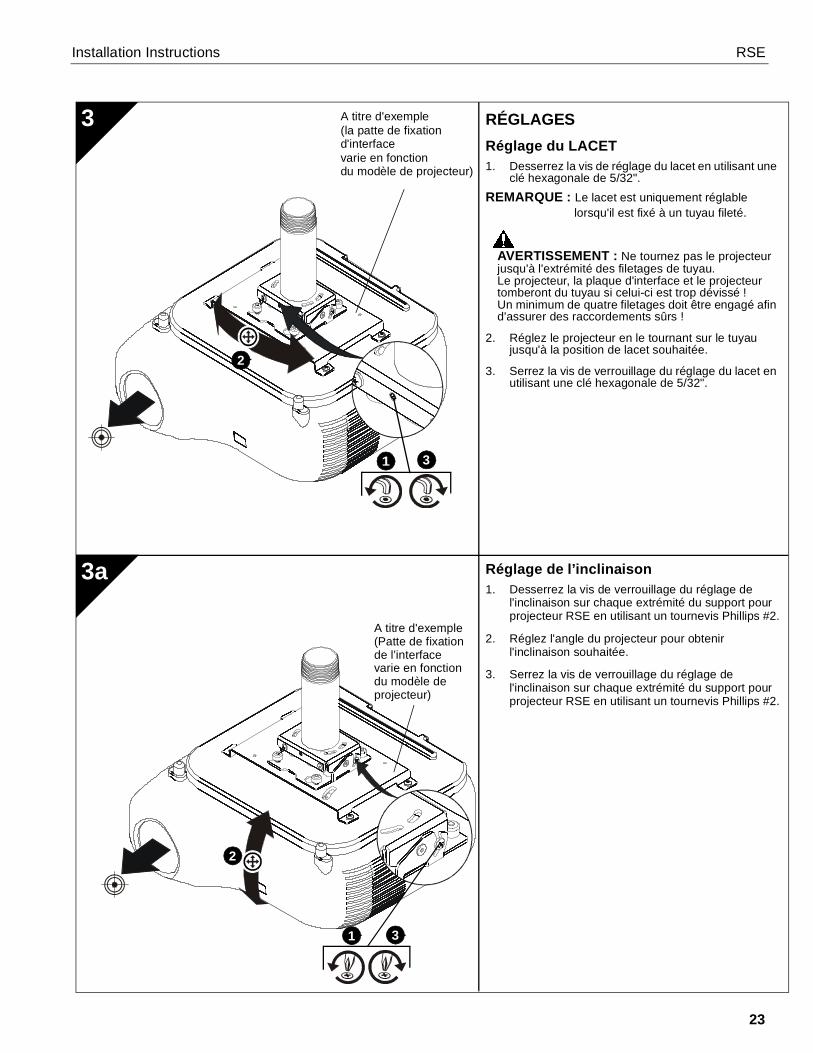
Pitch Adjustment1. Loosen pitch adjustment locking screw on each end
of the RSE projector mount using a #2 Phillipsscrewdriver.
2. Adjust projector angle to desired pitch.
3. Tighten pitch adjustment locking screw on each endof the RSE projector mount using a #2 Phillipsscrewdriver.
ADJUSTMENTSYAW Adjustment1. Loosen yaw adjustment screw using a 5/32" hex
key.NOTE: Yaw is only adjustable when attached to a
threaded pipe.
WARNING: Do not turn the projector to the end ofthe pipe threads. The projector, interface plate andprojector will fall from the pipe if it is unthreaded toofar! A minimum of four threads must be engaged inorder to ensure a secure connection!
2. Adjust projector by turning the projector on the pipeto the desired yaw position.
3. Tighten yaw adjustment locking screw using a 5/32"hex key.
3a
3 Example Only(Interface bracketvaries dependenton projector model)
Example Only(Interface bracketvaries dependenton projector model)
1 3
2
1 3
2

Installation Instructions RSE
13
Roll Adjustment1. Loosen roll adjustment locking screw on each side
of the RSE projector mount using a #2 Phillipsscrewdriver.
2. Adjust projector to desired roll position.
3. Tighten roll adjustment locking screw on each sideof the RSE projector mount using a #2 Phillipsscrewdriver.
3b 1
3
2
Example Only(Interface bracketvaries dependenton projector model)

RSE Installation Instructions
14
CLAUSES DE NON-RESPONSABILITÉMilestone AV Technologies, ses filiales et entreprises affiliées(« Milestone ») ont fait en sorte que ce manuel soit exact etexhaustif. Cependant, Milestone ne garantit pas que lesinformations mentionnées au présent document couvrent tousles aspects, conditions ou variations dans le détail ; pas plusqu'elle ne fournit de solution pour chaque imprévu lié au typed'installation ou d'utilisation de ce produit. Les informationsmentionnées au présent document sont susceptibles d'êtremodifiées sans aucun préavis ni obligation. Milestone neconsent aucune garantie, expresse ou implicite, au titre desinformations contenues dans le présent document. Milestonene garantit pas que les informations mentionnées au présentdocument soient exactes, exhaustives et suffisantes.Chief® est une marque déposée de Milestone AVTechnologies. Tous droits réservés.
DIRECTIVES DE SÉCURITÉ IMPORTANTES !
AVERTISSEMENT : Un AVERTISSEMENT vous indiquequ'il existe un risque de blessures graves ou de décès sivous ne suivez pas les instructions.
MISE EN GARDE : Une MISE EN GARDE vous indiquequ'il existe un risque de dommages ou de destruction dumatériel si vous ne suivez pas les instructionscorrespondantes.
AVERTISSEMENT : Le fait de ne pas lire, de ne pas biencomprendre et de ne pas suivre toutes les instructions peutentraîner des blessures corporelles graves, endommagerl'équipement ou annuler la garantie du fabricant ! Il est de laresponsabilité de l'installateur de s'assurer que tous lescomposants sont correctement montés et installésconformément aux instructions fournies.
AVERTISSEMENT : Une résistance structurelle nonappropriée pour ce composant peut entraîner des blessurescorporelles graves ou endommager l'équipement ! Il est de laresponsabilité de l'installateur de s'assurer que la structure à
laquelle ce composant est attaché peut supporter cinq fois lepoids total de l'équipement. Si nécessaire, renforcez lastructure avant d'installer cet élément.
AVERTISSEMENT : Le dépassement de capacité de poidspeut causer de graves blessures corporelles ou endommagerle matériel ! Il est de la responsabilité de l'installateur des'assurer que le poids total de tous les composants fixés auRSE ne dépasse pas 11,37 kg (25 lbs).
• La capacité de poids du RSE peut être LIMITÉE à lacapacité de poids la plus basse de tout autre élémentsitué entre le RSE et la structure de support !
AVERTISSEMENT : N'utiliser ce système de montage quepour l'usage prévu conformément à ces directives. Ne pasutiliser d'accessoires non recommandés par le fabricant.
AVERTISSEMENT : Ne jamais faire fonctionner ce systèmede montage s'il est endommagé. Dans ce cas, renvoyer lesystème à un service technique pour examen et réparation.
AVERTISSEMENT : Ne pas utiliser ce produit à l'extérieur.
IMPORTANT ! : Ces supports RSE sont conçus pour être :• fixés à une colonne d'extension en acier ou en
aluminium NPT ou NPSM de 1-1/2" ; ou• fixés à des doubles contreventements transversaux de
montants en bois de 51 mm x 102 mm (2" x 4")(38,1 mm / 1-1/2" au centre) entre deux solives deplafond de 51 mm x 102 mm (2" x 4") ;
• fixés à un plafond en béton d'une épaisseur minimumde 203 mm (8") et avec un un revêtement de cloisonsèche d'épaisseur maximale de 16 mm (5/8") ; ou
• suspendus à l'aide de quatre tiges filetées (nonincluses) #10-24 de diamètre (minimum), qui sontfixées à des membres structurels en hauteurd'assemblage de canal, d'angle ou Unistrut (fermes oupoutrelles) par des contre-écrous #10 (non inclus).
--RANGER CES CONSIGNES EN LIEU SÛR--
DIMENSIONS
1.4436.6
4.38111.1
1.4436.5
3.1078.8

Installation Instructions RSE
15
OUTILS NÉCESSAIRES À L'INSTALLATION
PIÈCES
11 mm
2,4 mm (3/32") (bois)6,4 mm (1/4") (béton)
#2
Matériel requis - non inclus(en fonction de la méthode d'installation)
1. Installation sur une colonne d'extension filetée• Colonne d'extension filetée en aluminium ou en acier NPT ou
NPSM 1-1/2" pouvant supporter 22,7 kg ou plus
2. Installation sur des solives de plafond en bois
• Vis à bois à tête Phillips #10 x 3" (Qté 4)• Rondelles #10 (Qté 4)
3. Installation sur un plafond en béton
• Brides d'ancrage de 3/8" x 2-1/4"de qualité 2 (Qté 4)• Rondelles #10 (Qté 4)• Vis à bois à tête Phillips #10 x 3" (Qté 4)
4. Installation sur des tiges filetées
• Tiges filetées en acier #10-24 (Qté 4)• Écrous crénelés #10-24 (Qté 4)• Contre-écrous #10-24 (Qté 8)• Rondelles #10 (Qté 8)
(7/16")
4,0 mm (5/32") – sécurité (fournis)
M6 (fournis)
Kit de
(en option)
A (1)
du modèle de projecteur)
A titre d'exemple(la patte de fixationd'interface varie en fonction
B (1)
[RSE]
C (2)M16 x 6 mm
D (2)M16 x 6 mm (sécurité)
sécuritéAll-Point
G (1)M6E (2)
M6
F (2)M6

RSE Installation Instructions
16
Retrait de l'adaptateur CPA
REMARQUE : Si vous installez le RSE à autre chosequ'une colonne CPA, la pièced'adaptation CPA doit être retirée dusupport RSE avant l'installation.
1. Desserrez la vis d'arrêt maintenant l'adaptateurCPA sur le support RSE.
2. Tournez l'adaptateur CPA dans le sens contrairedes aiguilles d'une montre jusqu'à ce que le filetagene soit plus engagé dans le RSE.
3. Retirez l'adaptateur CPA du RSE.
INSTALLATION DU RSEInstallation sur un tuyau CPA1. Choisissez soigneusement l'emplacement de
fixation souhaité.IMPORTANT ! : Cela impliquera de connaître ladistance entre la lentille et l'écran. Voir lescaractéristiques du projecteur pour plus dedétails sur la manière de déterminer cettedistance.
2. Assurez-vous que les trous sont alignés surl'adaptateur CPA du RSE et la colonne CPA du RSE(non incluse), soulevez le RSE jusqu'à l'ouvertureen bas de la colonne CPA. (Voir la Figure 1)
3. Installez une vis à tête bouton M6 x 16 (C) ou unevis de sécurité (D) dans le trou sur le côté du tuyauCPA, où la plaque adaptatrice de l'adaptateur CPAest située.
4. Sur le côté opposé du tuyau CPA, utilisez l'autre visà tête bouton M6 x 16 (C) ou l'autre vis de sécurité(D) pour fixer le RSE (A) à la colonne CPA.
5. Utilisez une clé hexagonale M6 en forme de « L »pour serrer le boulon inférieur qui fixe le RPME à lacolonne d'extension.
6. Passez à la section « Installation du projecteur ».
1a
13
2Tuyau CMA(non fourni)
4
(C) ou (D)
(C) ou (D)
adaptateur CPA
trou sur le côtéde la plaque
2
3
1
adaptateurCPA
adaptatrice
(F) x 2
(E) x 2
5

Installation Instructions RSE
17
(A)
1
2
4
2
(A)
3
INSTALLATION DU RSEInstallation sur un tuyau filetéREMARQUE : L'adaptateur CPA doit être retiré avant
d'installer le RSE sur le tuyau fileté.Reportez-vous à la section 1a pourplus de détails.
1. Choisissez soigneusement l'emplacement defixation souhaité.
IMPORTANT ! : Cela impliquera de connaître ladistance entre la lentille et l'écran. Voir lescaractéristiques du projecteur pour plus dedétails sur la manière de déterminer cettedistance.
2. Installez une colonne d'extension en aluminium ou enacier NPT ou NPSM de 1-1/2" (non incluse) dans lecollier fileté jusqu'à ce qu'elle soit bien serrée, avec unminimum de quatre filetages engagés.
AVERTISSEMENT : UNE MAUVAISEINSTALLATION PEUT ENTRAÎNER DES BLESSURESCORPORELLES GRAVES ! Les éléments structurelsDOIVENT être capables de supporter cinq fois le poidstotal de l'équipement monté.
3. Alignez le RSE avec l'extrémité du tuyau NPT.
4. Vissez le RSE au tuyau en tournant dans le senscontraire des aiguilles d'une montre jusqu'à ce qu'il
Alignement approximatif du RSE
1. Tournez le RSE dans le sens des aiguilles d'unemontre ou dans le sens contraire des aiguillesd'une montre, jusqu'à ce que l'avant du support sesitue face à la cible.
IMPORTANT ! : Lorsque le RSE estcorrectement positionné, le trou d'accès à la visd'arrêt doit directement être orienté vers la cible.(Voir le détail de la partie inférieure dans la figurede gauche.)
2. Fixez le RSE au tuyau en tournant la vis d'arrêtavec une clé hexagonale de 5/32" jusqu'à cequ'elle soit bien serrée.
MISE EN GARDE : NE PAS TROP SERRER !Un serrage excessif de la vis d'arrêt peut endommagerle filetage du tuyau.
1b
1
(non fourni)
(non fourni)

RSE Installation Instructions
18
1c Installation sur des montants en boisREMARQUE : L'adaptateur CPA doit être retiré avant
d'installer le RSE sur des montants enbois. Reportez-vous à la section 1a pourplus de détails.
1. Choisissez soigneusement l'emplacement defixation souhaité.
IMPORTANT ! : Cela impliquera de connaître ladistance entre la lentille et l'écran. Voir lescaractéristiques du projecteur pour plus de détailssur la manière de déterminer cette distance.
AVERTISSEMENT : UNE MAUVAISEINSTALLATION PEUT ENTRAÎNER DES BLESSURESCORPORELLES GRAVES ! Les éléments structurelsDOIVENT être capables de supporter cinq fois le poidstotal de l'équipement monté.
IMPORTANT ! : Les supports RSE sont conçus pourêtre montés sur des doubles contreventementstransversaux de montants en bois en bois de51 mm x 102 mm (2" x 4") (38,1 mm / 1-1/2" au centre)entre deux solives de plafond.
2. En utilisant le RSE comme guide, marquez lesquatre emplacements des trous de montageà l'aide d'un crayon ou d'un outil similaire.Les emplacements des trous doivent êtrecentrés sur les contreventements transversaux de51 mm x 102 mm (2" x 4").
3. Percez quatre trous de guidage de 2,5 mm (3/32")de diamètre à une profondeur de 45 mm (1-3/4").
4. Alignez les quatre trous de montage du RSE sur lesquatre trous de guidage.
IMPORTANT ! : Assurez-vous que le support estcorrectement orienté vers la cible avant de fixer lastructure.
5. Fixez le RSE à la structure en utilisant quatrerondelles plates #10 et quatre vis à bois à têtePhillips #10 x 3" (non incluses).
X4
X4
3
1
2
4
Ø 2.5mm(Ø 3/32”)
45mm(1-3/4”)
5
(A)
x 4

Installation Instructions RSE
19
1d
Ø 6.3mm(Ø 1/4”)
64mm(2-1/2”)
Installation sur béton solideREMARQUE : L'adaptateur CPA doit être retiré
avant d'installer le RSE sur du béton.Reportez-vous à la section 1a pourplus de détails.
1. Déterminez l'emplacement de montage.
AVERTISSEMENT : Le RSE est conçu pour êtremonté sur un plafond en béton d'une épaisseurminimum de 203 mm (8") et avec un revêtement decloison sèche d'une épaisseur maximale de 16 mm (5/8").
AVERTISSEMENT : UNE MAUVAISEINSTALLATION PEUT ENTRAÎNER DES BLESSURESCORPORELLES GRAVES ! Les éléments structurelsDOIVENT être capables de supporter cinq fois le poidstotal de l'équipement monté.
2. En utilisant le RSE comme guide, marquez lesquatre emplacements des trous de montage sur leplafond à l'aide d'un crayon ou d'un outil similaire.
3. Percez quatre trous de guidage de 6,3 mm (1/4") dediamètre à une profondeur de 64 mm (2-1/2").
4. Alignez les quatre trous de montage du RSE sur lesquatre trous de guidage.
IMPORTANT ! : Assurez-vous que le support estcorrectement orienté vers la cible avant de fixer lastructure.
AVERTISSEMENT : Les vis d'ancrage (nonfournies) doivent être installées dans du béton solide,structurellement homogène. Toute installation dansun bloc de béton creux ou dans du béton présentantdes fissures, un effritement ou tout autre défaut peutentraîner la chute du dispositif d'ancrage etprovoquer de graves blessures corporelles ouendommager le matériel.
5. Installez quatre brides d'ancrage pour béton de3/8" x 2-1/4"(non incluses) en les insérant dansles trous de guidage et en les martelant jusqu'àaffleurer la surface de montage.
6. Fixez le RSE à la structure en utilisant quatrerondelles plates #10 et quatre vis à bois à têtePhillips #10 x 3". (non fournies)
3
X4
X4
1
2
(A)
5
X4
6
X (4)

RSE Installation Instructions
20
INSTALLATION DU PROJECTEURIMPORTANT ! : Le modèle RSE utilise des pattesde fixation d'interface de série « SSB » de Chief, enoption. (Voir le dessin Pièces.)
Installez la patte de fixation d'interface1. Vissez partiellement les écrous à ailettes sur les vis
Phillips jusqu'à ce que la vis d'arrêt soit visible enhaut de la vis de serrage.
IMPORTANT ! : NE serrez PAS complètement lesvis de serrage tout de suite.
Installation sur tiges filetéesREMARQUE : L'adaptateur CPA doit être retiré avant
d'installer le RPE sur les tiges filetées.Reportez-vous à la section 1a pour plusde détails.
Le RSE doit être suspendu à l'aide de quatre tigesfiletées (non incluses) #10-24 de diamètre (minimum),qui sont fixées à des membres structurels en hauteurd'assemblage de canal, d'angle ou Unistrut (armaturesou poutrelles) par des contre-écrous #10-24 (non inclus).
AVERTISSEMENT : UNE MAUVAISEINSTALLATION PEUT ENTRAÎNER DES BLESSURESCORPORELLES GRAVES ! Les éléments structurelsDOIVENT être capables de supporter cinq fois le poidstotal de l'équipement monté.
1. Choisissez soigneusement la position de fixationsouhaitée.
IMPORTANT ! : Cela impliquera de connaître ladistance entre la lentille et l'écran. Voir lescaractéristiques du projecteur pour déterminercette distance.
REMARQUE : Tige filetée et matériel d'installationnon inclus.
2. Fixez une extrémité de la tige filetée à l'élémentstructurel.
3. Installez quatre contre-écrous #10-24 sur chaquetige filetée.
4. Installez le RSE sur la tige filetée.
REMARQUE : Le trou dans le RSE permet l'accèsavec une clef à douille sans avoir àdémonter l'unité.
5. Fixez le RSE à la tige filetée en utilisant quatreécrous crénelés #10.
2
1e
A titre d'exemple(la patte de fixation d'interfacevarie en fonctiondu modèle de projecteur)
2
2
(A)
1 2
4
X 45

Installation Instructions RSE
21
Installation du projecteur avec la pattede fixation1. Orientez le projecteur avec la patte d'interface
comme indiqué dans l'illustration 2b à gauche.
2. Soulevez le projecteur afin que les vis et les écrousà ailettes soient alignés aux fentes de fixation dansla base de montage.
3. Glissez le projecteur avec la patte de fixation dansles fentes de fixation de la base du montage jusqu'àce que les vis soient ancrées à l'arrière des fentesde fixation. Voir les figures 2b et 2c.
AVERTISSEMENT : UNE MAUVAISEINSTALLATION PEUT PROVOQUER LA CHUTE DUPROJECTEUR ET ENDOMMAGER CELUI-CI,VOIRE ENTRAÎNER DES BLESSURESCORPORELLES GRAVES. Assurez-vous que lesfentes de fixation dans la base de montage glissentsous les vis de serrage et que les vis sont ancrées àl'arrière des fentes.
AVERTISSEMENT : UNE MAUVAISEINSTALLATION PEUT PROVOQUER LA CHUTE DUPROJECTEUR ET ENDOMMAGER CELUI-CI, VOIREENTRAÎNER DES BLESSURES CORPORELLESGRAVES. NE PAS substituer le matériel. Utilisezuniquement le matériel fourni par le fabricant.
1. Fixez la patte de fixation au support en suivant lesinstructions d'installation et en utilisant le matérielfourni avec la patte de fixation.
REMARQUE : Les pattes d'interface peuvent êtreinstallées en utilisant le Kit de sécuritéAll-Points en option inclus avec lessolutions de fixation SSB.
2b
2a
(A)
1
1
A titre d'exemple(la patte de fixation d'interfacevarie en fonctiondu modèle de projecteur)
A titre d'exemple(la patte de fixation
varie en fonctiondu modèle de projecteur)
d'interface

RSE Installation Instructions
22
Fixation du projecteur avec la patted'interface au support de modèle RSE
AVERTISSEMENT : UNE MAUVAISEINSTALLATION PEUT PROVOQUER LA CHUTE DUPROJECTEUR ET ENDOMMAGER CELUI-CI,VOIRE ENTRAÎNER DES BLESSURESCORPORELLES GRAVES. Assurez-vous que lesfentes de fixation dans la base de montage glissentsous les vis de serrage et que les vis sont ancrées àl'arrière des fentes.
1. Tournez les écrous à ailettes jusqu'à ce qu'il soientbien serrés pour fixer le projecteur au support.
2c
1 X 4
A titre d'exemple(la patte de fixation
varie en fonctiondu modèle de projecteur)
d'interface
Installation Instructions RSE
23
Réglage de l’inclinaison1. Desserrez la vis de verrouillage du réglage de
l'inclinaison sur chaque extrémité du support pourprojecteur RSE en utilisant un tournevis Phillips #2.
2. Réglez l'angle du projecteur pour obtenirl'inclinaison souhaitée.
3. Serrez la vis de verrouillage du réglage del'inclinaison sur chaque extrémité du support pourprojecteur RSE en utilisant un tournevis Phillips #2.
RÉGLAGESRéglage du LACET1. Desserrez la vis de réglage du lacet en utilisant une
clé hexagonale de 5/32".REMARQUE : Le lacet est uniquement réglable
lorsqu'il est fixé à un tuyau fileté.
AVERTISSEMENT : Ne tournez pas le projecteurjusqu'à l'extrémité des filetages de tuyau.Le projecteur, la plaque d'interface et le projecteurtomberont du tuyau si celui-ci est trop dévissé !Un minimum de quatre filetages doit être engagé afind'assurer des raccordements sûrs !
2. Réglez le projecteur en le tournant sur le tuyaujusqu'à la position de lacet souhaitée.
3. Serrez la vis de verrouillage du réglage du lacet enutilisant une clé hexagonale de 5/32".
3a
3 A titre d'exemple(la patte de fixation
varie en fonctiondu modèle de projecteur)
A titre d'exemple(Patte de fixation
varie en fonctiondu modèle de
1 3
2
1 3
2
de l’interface
projecteur)
d'interface
RSE Installation Instructions
24
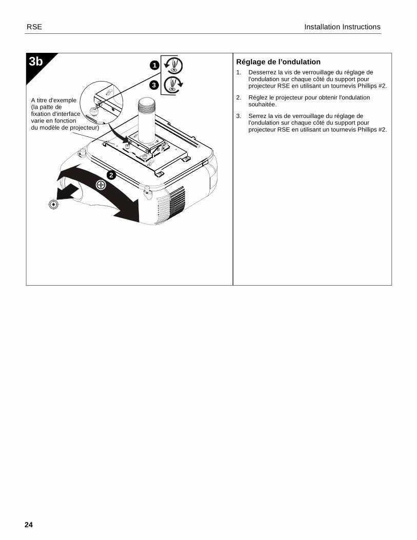
Réglage de l’ondulation1. Desserrez la vis de verrouillage du réglage de
l'ondulation sur chaque côté du support pourprojecteur RSE en utilisant un tournevis Phillips #2.
2. Réglez le projecteur pour obtenir l'ondulationsouhaitée.
3. Serrez la vis de verrouillage du réglage del'ondulation sur chaque côté du support pourprojecteur RSE en utilisant un tournevis Phillips #2.
3b 1
3
2
A titre d'exemple(la patte de
varie en fonctiondu modèle de projecteur)
fixation d'interface

Installation Instructions RSE
25
HAFTUNGSAUSSCHLUSSMilestone AV Technologies sowie seine konzerneigenenUnternehmen und Tochtergesellschaften (zusammen "Milestone")haben versucht, dieses Handbuch so genau und vollständig alsmöglich zu gestalten. Milestone erhebt jedoch weder Anspruch aufVollständigkeit der Einzelheiten, Bedingungen und Änderungen derhierin enthaltenen Informationen, noch übernimmt das Unternehmenirgendeine Haftung für eventuelle Schadensfälle in Verbindung mit derInstallation oder Verwendung dieses Produkts. Die in diesemDokument enthaltenen Informationen können ohne vorherigeAnkündigung oder sonstige Verpflichtungen jederzeit geändertwerden. Milestone schließt jegliche ausdrückliche oderstillschweigende Zusicherung und Gewährleistung bezüglich derhierin enthaltenen Informationen aus. Milestone übernimmt keinerleiVerantwortung für die Genauigkeit, Vollständigkeit oderAngemessenheit der in diesem Dokument enthaltenen Informationen.Chief® ist eine eingetragene Marke von Milestone AVTechnologies. Alle Rechte vorbehalten.
WICHTIGE SICHERHEITSHINWEISE!
WARNUNG: WARNUNG weist darauf hin, dass beiNichtbefolgung der Anweisungen Verletzungs- oder Lebensgefahrbesteht.
VORSICHT: VORSICHT weist darauf hin, dass bei Nichtbefolgungder Anweisungen die Möglichkeit von Geräteschäden besteht.
WARNUNG: Die Nichtbefolgung dieser Anweisungen kann zuschweren Verletzungen und Geräteschäden sowie zumErlöschen der Garantie führen. Der Monteur hat dafür zu sorgen,dass alle Bauelemente nach den beiliegenden Anweisungenmontiert und installiert werden.
WARNUNG: Wenn dieses Bauelement nicht an einerKonstruktion mit der erforderlichen Tragfähigkeit montiert wird,kann dies zu schweren Verletzungen oder Geräteschädenführen! Der Monteur hat dafür zu sorgen, dass die Konstruktion,an der das Bauelement angebracht wird, über die erforderlicheTragfähigkeit verfügt. Die Konstruktion muss das fünffache
Gesamtgewicht des Geräts tragen können. Verstärken Sie vorder Montage des Bauelements ggf. die Konstruktion.
WARNUNG: Das Überschreiten der maximalen Tragkraftkann zu schweren Verletzungen oder Geräteschäden führen!Der Monteur ist dafür verantwortlich, sicherzustellen, dass dasGesamtgewicht aller Komponenten, die mit der RSE verbundensind, 11,37 kg (25 lbs) nicht überschreitet.
• Die maximale Tragkraft der RSE ist auf die maximaleTragkraft des zwischen der RSE und der tragendenKonstruktion verwendeten sonstigen Bauelements mitder jeweils niedrigsten Tragkraft BESCHRÄNKT!
WARNUNG: Verwenden Sie das Halterungssystem nur fürden vorgesehenen, in der Anleitung beschriebenen Zweck.Verwenden Sie keine Zubehörteile, die nicht vom Herstellerempfohlen wurden.
WARNUNG: Verwenden Sie das Halterungssystem nie inbeschädigtem Zustand. Bringen Sie das Halterungssystem in diesemFall für die Fehlersuche und Reparatur zu einem Service-Center.
WARNUNG: Verwenden Sie das Produkt nie im Freien.WICHTIG! RSE-Halterungen eignen sich für:
• die Montage an eine Ausziehsäule mit 1-1/2"-NPT-oder NPSM-Gewinde aus Stahl oder Aluminium oder
• die Montage an einer doppelten Querverstrebung(38,1 mm / 1-1/2" von Mitte zu Mitte) aus 51 mm x102 mm (2" x 4")-Holzbalken zwischen zwei 51 mm x102 mm (2" x 4") Deckenbalken;
• die Montage an eine Betondecke mit einer Mindeststärkevon 203 mm (8") und einer Gipskartonbeschichtung vonmaximal 16 mm (5/8"); oder
• die Aufhängung an vier (nicht mitgelieferten)Gewindestangen mit einem Durchmesser vonmindestens Nr. 10-24, die mittels (nicht mitgelieferter)Nr. 10-Rechteckmuttern an Unistrut-, eckigen oderU-Eisen-Deckenbauteilen (Auslegern oder I-Trägern)befestigt werden.
--BEWAHREN SIE DIESE ANWEISUNGEN AUF--

RSE Installation Instructions
26
ABMESSUNGEN
FÜR DIE MONTAGE ERFORDERLICHES WERKZEUG
TEILE
1.4436.6
4.38111.1
1.4436.5
3.1078.8
PUNKTZUR EINSTELLUNG DESQUERNEGUNGSWINKELS
PUNKT ZUR EINSTELLUNG DERDREHUNG UMDIE QUERACHSE
11 mm
2,4 mm (3/32") (Holz)6,4 mm (1/4") (Beton)
Nr. 2
Erforderliche Befestigungsmaterialien –nicht mitgeliefert
(abhängig von der Installationsmethode)
1. Montage an einer Ausziehsäule mit Gewinde• Ausziehsäule mit 1-1/2"-NPT- oder NPSM-Gewinde aus
Stahl oder Aluminium, die für 22,7 kg (50 lbs) oder mehrzugelassen ist
2. Montage an Holzdeckenbalken
• Nr. 10 x 3" Kreuzschlitzholzschrauben (4 Stk.)• Nr. 10 Unterlegscheiben (4 Stk.)
3. Montage an Beton
• 3/8" x 2-1/4" Betondübel Klasse 2 (4 Stk.)• Nr. 10 Unterlegscheiben (4 Stk.)• Nr. 10 x 3" Kreuzschlitzholzschrauben (4 Stk.)
4. Montage an Gewindestange
• Nr. 10-24 Stahlgewindestangen (4 Stk.)• Nr. 10-24 Rechteckmuttern (4 Stk.)• Nr. 10-24 Kontermuttern (8 Stk.)• Nr. 10 Unterlegscheiben (8 Stk.)
(7/16")
4,0 mm (5/32") - Sicherheit (mitgeliefert)
M6 (mitgeliefert)

Installation Instructions RSE
27
All-Points-Sicherheits-paket (Optional)
A (1)
modell verschieden)
Nur ein Beispiel(Anschlussplatteje nach Projektor-
B (1)
[RSE]
C (2)M16x6mm
D (2)M16x6mm (Sicherheit)
G (1)M6
E (2)M6
F (2)M6
A (1)[RSE]

RSE Installation Instructions
28
Entfernen des CPA-Adapters
HINWEIS: Falls Sie die RSE an etwas anderes alseine CPA-Säule montieren, muss derCPA-Adapter vor der Montage von derRSE-Halterung entfernt werden.
1. Lösen Sie die Feststellschraube, die denCPA-Adapter an der RSE-Halterung fixiert.
2. Drehen Sie den CPA -Adapter gegen denUhrzeigersinn, bis sich das Gewinde aus derRSE löst.
3. Entfernen Sie den CPA-Adapter aus der RSE.
MONTAGE DER RSEMontage eines CPA-Rohrs1. Wählen Sie sorgfältig eine Montagestelle aus.WICHTIG! Hierzu müssen Sie den Abstandzwischen Linse und Leinwand kennen. Dietechnischen Daten des Projektors bieten IhnenInformationen zur Bestimmung dieses Abstands.
2. Schieben Sie die RSE so in die untere Öffnung der(nicht mitgelieferten) CPA-Säule, dass die Löcherdes CPA-Adapters der RSE und der CPA-Säulegenau übereinander liegen.
3. Schrauben Sie entweder eine M6x16-Halbrundkopfschraube (C) oder eineSicherheitsschraube (D) durch eine M6-Sicherungsscheibe (E) und ein flache M6-Unterlegscheibe (F) in das Loch auf der Seite desCDA-Rohrs, auf der sich die Adapterplatte desCPA-Adapters befindet.
4. Benutzen Sie (A) auf der gegenüberliegendenSeite des CPA-Rohrs die andere M6x16-Halbrundkopfschraube (C) oderSicherheitsschraube (D), eine M6-Sicherungsscheibe (E) und ein flache M6-Unterlegscheibe (F), um RPME (A) an der CPA-Säule zu befestigen.
5. Benutzen Sie den „L“-förmigen M6-Inbusschlüssel(E), um die Bodenschraube anzuziehen, durch diedie RPME an der Ausziehsäule befestigt ist.
6. Fahren Sie beim Abschnitt "Montage desProjektors" fort.
1a
13
2CPA-Rohr
(nicht mitgeliefert)
4
(C) oder (D)
(C) oder (D)
CPA-Adapter
Loch auf der Seiteder Adapterplatte
2
3
1
CPA-Adapter
(F) x 2
(E) x 2
2
Installation Instructions RSE
29
(A)
1
2
4
2
(A)
3
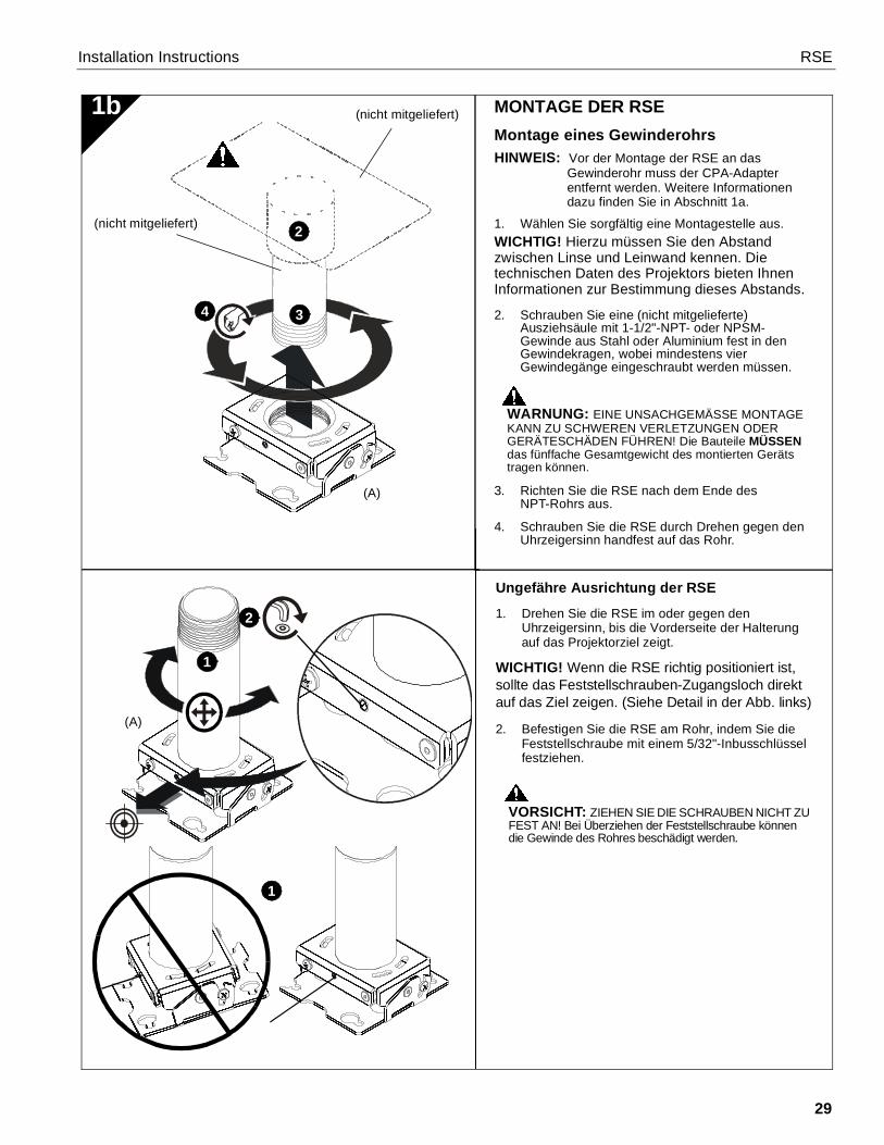
MONTAGE DER RSEMontage eines GewinderohrsHINWEIS: Vor der Montage der RSE an das
Gewinderohr muss der CPA-Adapterentfernt werden. Weitere Informationendazu finden Sie in Abschnitt 1a.
1. Wählen Sie sorgfältig eine Montagestelle aus.WICHTIG! Hierzu müssen Sie den Abstandzwischen Linse und Leinwand kennen. Dietechnischen Daten des Projektors bieten IhnenInformationen zur Bestimmung dieses Abstands.
2. Schrauben Sie eine (nicht mitgelieferte)Ausziehsäule mit 1-1/2"-NPT- oder NPSM-Gewinde aus Stahl oder Aluminium fest in denGewindekragen, wobei mindestens vierGewindegänge eingeschraubt werden müssen.
WARNUNG: EINE UNSACHGEMÄSSE MONTAGEKANN ZU SCHWEREN VERLETZUNGEN ODERGERÄTESCHÄDEN FÜHREN! Die Bauteile MÜSSENdas fünffache Gesamtgewicht des montierten Gerätstragen können.
3. Richten Sie die RSE nach dem Ende desNPT-Rohrs aus.
4. Schrauben Sie die RSE durch Drehen gegen denUhrzeigersinn handfest auf das Rohr.
Ungefähre Ausrichtung der RSE
1. Drehen Sie die RSE im oder gegen denUhrzeigersinn, bis die Vorderseite der Halterungauf das Projektorziel zeigt.
WICHTIG! Wenn die RSE richtig positioniert ist,sollte das Feststellschrauben-Zugangsloch direktauf das Ziel zeigen. (Siehe Detail in der Abb. links)
2. Befestigen Sie die RSE am Rohr, indem Sie dieFeststellschraube mit einem 5/32"-Inbusschlüsselfestziehen.
VORSICHT: ZIEHEN SIE DIE SCHRAUBEN NICHT ZUFEST AN! Bei Überziehen der Feststellschraube könnendie Gewinde des Rohres beschädigt werden.
1b
1
(nicht mitgeliefert)
(nicht mitgeliefert)

RSE Installation Instructions
30
1c Montage an HolzbalkenHINWEIS: Vor der Montage der RSE an Holzbalken
muss der CPA-Adapter entfernt werden.Weitere Informationen dazu finden Sie inAbschnitt 1a.
1. Wählen Sie sorgfältig eine Montagestelle aus.
WICHTIG! Hierzu müssen Sie den Abstandzwischen Linse und Leinwand kennen. Dietechnischen Daten des Projektors bieten IhnenInformationen zur Bestimmung dieses Abstands.
WARNUNG: EINE UNSACHGEMÄSSE MONTAGEKANN ZU SCHWEREN VERLETZUNGEN ODERGERÄTESCHÄDEN FÜHREN! Die Bauteile MÜSSENdas fünffache Gesamtgewicht des montierten Gerätstragen können.
WICHTIG! RSE-Halterungen eignen sich für dieMontage an einer doppelten Querverstrebung(38,1 mm / 1-1/2" von Mitte zu Mitte) aus 51 mm x102 mm (2" x 4")-Holzbalken zwischen zweiDeckenbalken.
2. Zeichnen Sie mithilfe der RSE als Schablone miteinem Bleistift oder Ähnlichem vier Bohrstellen an.Die Bohrstellen müssen jeweils in der Mitte zweier51 mm x 102 mm (2" x 4")-Querstreben angebrachtwerden.
3. Bohren Sie vier Vorbohrungen mit einemDurchmesser von 2,5 mm (3/32") und einer Tiefevon 45 mm (1-3/4").
4. Richten Sie die vier Montagebohrungen in der RSEnach den vier Vorbohrungen aus.
WICHTIG! Stellen Sie sicher, dass die Halterunggenau auf das Ziel gerichtet ist, bevor Sie sie ander Konstruktion befestigen.
5. Befestigen Sie die RSE mit vier Nr. 10-Unterlegscheiben und vier Nr.10 x 3"-Kreuzschlitzholzschrauben (nicht mitgeliefert) ander Konstruktion.
X4
X4
3
1
2
4
Ø 2.5mm(Ø 3/32”)
45mm(1-3/4”)
5
(A)
x 4

Installation Instructions RSE
31
1d
Ø 6.3mm(Ø 1/4”)
64mm(2-1/2”)
Montage an MassivbetonHINWEIS: Vor der Montage der RSE an Beton
muss der CPA-Adapter entfernt werden.Weitere Informationen dazu finden Sie inAbschnitt 1a.
1. Wählen Sie eine Montagestelle aus.
WARNUNG: Die RSE eignet sich zur Montage an eineBetondecke mit einer Mindeststärke von 203 mm (8") undeiner Gipskartonbeschichtung von maximal 16 mm (5/8").
WARNUNG: EINE UNSACHGEMÄSSE MONTAGEKANN ZU SCHWEREN VERLETZUNGEN ODERGERÄTESCHÄDEN FÜHREN! Die Bauteile MÜSSENdas fünffache Gesamtgewicht des montierten Gerätstragen können.
2. Zeichnen Sie mithilfe der RSE als Schablone miteinem Bleistift oder Ähnlichem vier Bohrstellen andie Decke.
3. Bohren Sie vier Vorbohrungen mit einemDurchmesser von 6,3 mm (1/4") und einer Tiefe von64 mm (2-1/2").
4. Richten Sie die vier Montagebohrungen in der RSEnach den vier Vorbohrungen aus.
WICHTIG! Stellen Sie sicher, dass die Halterunggenau auf das Ziel gerichtet ist, bevor Sie sie ander Konstruktion befestigen.
WARNUNG: Dübel (nicht mitgeliefert) müssen inbaulich intakte Massivbetondecken montiert werden.Die Installation in Hohlblockdecken, Mörtel oder Beton,der Risse, Absplitterungen oder andere Defekteaufweist, kann zu einem Versagen des Dübels undschweren Personen- oder Sachschäden führen.
5. Stecken Sie vier (nicht mitgelieferte) 3/8" x 2-1/4"-Betondübel in die Vorbohrungen und schlagen Siesie mit dem Hammer ein, bis sie bündig mit derBefestigungsfläche abschließen.
6. Befestigen Sie die RSE mit vier Nr. 10-Unterlegscheiben und vier Nr.10 x 3"-Kreuzschlitzholzschrauben an der Konstruktion.(nicht mitgeliefert)
3
X4
X4
1
2
(A)
5
X4
6
X (4)

RSE Installation Instructions
32
MONTAGE DES PROJEKTORSWICHTIG! Das RSE-Modell lässt sich mit denoptionalen Anschlussplatten der Chief-Serie"SSB" kombinieren. (Siehe Abb. Teile.)
Montieren der Anschlussplatte1. Schrauben Sie Flügelmuttern so weit auf die
Kreuzschlitzschrauben, bis das Schraubenende ander Oberseite der Flügelmutter zu sehen ist.
WICHTIG! Ziehen Sie die Flügelschrauben zudiesem Zeitpunkt noch NICHT vollständig fest.
Montage an GewindestangenHINWEIS: Vor der Montage der RSE an die
Gewindestangen muss der CPA-Adapterentfernt werden. Weitere Informationendazu finden Sie in Abschnitt 1a.
Die RSE muss an vier (nicht mitgelieferten)Gewindestangen mit einem Durchmesser vonmindestens Nr. 10-24 aufgehängt werden, die mittels(nicht mitgelieferter) Nr. 10-24-Rechteckmuttern anUnistrut-, eckigen oder U-Eisen-Deckenbauteilen(Auslegern oder I-Trägern) befestigt werden.
WARNUNG: EINE UNSACHGEMÄSSE MONTAGEKANN ZU SCHWEREN VERLETZUNGEN ODERGERÄTESCHÄDEN FÜHREN! Die Bauteile MÜSSENdas fünffache Gesamtgewicht des montierten Gerätstragen können.
1. Wählen Sie sorgfältig eine Montagestelle aus.WICHTIG! Hierzu müssen Sie den Abstandzwischen Linse und Leinwand kennen. Dietechnischen Daten des Projektors bieten IhnenInformationen zur Bestimmung dieses Abstands.HINWEIS: Gewindestangen und
Befestigungsmaterialien werdennicht mitgeliefert.
2. Befestigen Sie ein Ende der Gewindestangeam Bauteil.
3. Montieren Sie vier Nr. 10-24-Kontermuttern an denGewindestangen.
4. Montieren Sie die RSE an die Gewindestange.
HINWEIS: Das Loch in der RSE ermöglicht dieVerwendung eines Steckschlüssels, ohnedass das Bauteil auseinandergebautwerden muss.
5. Befestigen Sie die RSE mit vier Nr. 10-Rechteckmuttern an den Gewindestangen.
2
1e
Nur ein Beispiel(Anschlussplatteje nach Projektor-modell verschieden)
2
2
(A)
1 2
4
X 45

Installation Instructions RSE
33
Montage eines Projektors mitAnschlussplatte1. Richten Sie den Projektor mit der Anschlussplatte
so aus, wie links in Abb. 2b dargestellt.
2. Halten Sie den Projektor so, dass die Schraubenmit den Flügelmuttern nach den Montageschlitzenin der Montagebasis ausgerichtet sind.
3. Schieben Sie den Projektor mit der Anschlussplattein die Montageschlitze der Montagebasis, bis sichdie Schrauben am hinteren Ende der Schlitzebefinden. Siehe Abb. 2b und 2c.
WARNUNG: EINE UNSACHGEMÄSSE MONTAGEKANN ZUM HERUNTERFALLEN DES PROJEKTORSFÜHREN UND SCHWERE VERLETZUNGEN ODERGERÄTESCHÄDEN VERURSACHEN. Stellen Sie sicher,dass die Montageschlitze in der Montagebasis unter dieFlügelmuttern geschoben werden und dass sich dieSchrauben am hinteren Ende der Schlitze befinden.
WARNUNG: EINE UNSACHGEMÄSSE MONTAGEKANN ZUM HERUNTERFALLEN DES PROJEKTORSFÜHREN UND SCHWERE VERLETZUNGEN ODERGERÄTESCHÄDEN VERURSACHEN. Verwenden SieKEINE Ersatz-Befestigungsmittel. Verwenden Sie nurdie vom Hersteller mitgeliefertenBefestigungsmaterialien.
1. Befestigen Sie die Anschlussplatte mithilfe der derAnschlussplatte beiliegenden Montageanleitungund Befestigungsmaterialien an der Halterung.
HINWEIS: Anschlussplatten lassen sich mithilfe deroptionalen All-Points-Sicherheitspackung,die den SSB-Befestigungssystemenbeigelegt ist, montieren.
2b
2a
(A)
1
1
Nur ein Beispiel(Anschlussplatteje nach Projektor-modell verschieden)
Nur ein Beispiel(Anschlussplatteje nach Projektor-modell verschieden)

RSE Installation Instructions
34
Befestigen des Projektors mit derAnschlussplatte an der RSE-Halterung
WARNUNG: EINE UNSACHGEMÄSSE MONTAGEKANN ZUM HERUNTERFALLEN DES PROJEKTORSFÜHREN UND SCHWERE VERLETZUNGEN ODERGERÄTESCHÄDEN VERURSACHEN. Stellen Sie sicher,dass die Montageschlitze in der Montagebasis unter dieFlügelmuttern geschoben werden und dass sich dieSchrauben am hinteren Ende der Schlitze befinden.
1. Ziehen Sie die Flügelmuttern an, um den Projektoran der Halterung zu befestigen.
2c
1 X 4
Nur ein Beispiel(Anschlussplatteje nach Projektor-modell verschieden)

Installation Instructions RSE
35
Einstellung der Drehung um dieQuerachse1. Lösen Sie an den beiden Enden der RSE-
Projektorhalterung jeweils die Feststellschraube fürdie Einstellung der Drehung um die Querachse miteinem Nr. 2-Kreuzschlitzschraubendreher.
2. Stellen Sie den gewünschtenProjektorneigungswinkel ein.
3. Ziehen Sie an den beiden Enden der RSE-Projektorhalterung jeweils die Feststellschraube fürdie Einstellung der Drehung um die Querachse miteinem Nr. 2-Kreuzschlitzschraubendreher an.
EINSTELLUNGENEinstellung der Drehung um dieHÖHENACHSE1. Lösen Sie die Schraube für die Einstellung der
Drehung um die Höhenachse mit einem 5/32"-Inbusschlüssel.
HINWEIS: Die Drehung um die Höhenachse lässt sichnur in Verbindung mit einem Gewinderohrverstellen.
WARNUNG: Schrauben Sie den Projektor nicht bisans Ende des Rohrgewindes. Halterung, Anschlussplatteund Projektor fallen vom Rohr, wenn sie zu weitabgeschraubt werden! Um eine sichere Verbindung zugewährleisten, müssen mindestens vier Gewindegängeeingeschraubt bleiben.
2. Verdrehen Sie den Projektor am Rohr und bringenSie ihn so in die gewünschte Position.
3. Ziehen Sie die Feststellschraube für die Einstellungder Drehung um die Höhenachse mit einem 5/32"-Inbusschlüssel fest.
3a
3 Nur ein Beispiel(Anschlussplatteje nach Projektor-modell verschieden)
Nur ein Beispiel(Anschlussplatteje nach Projektor-modell verschieden)
1 3
2
1 3
2

Installation Instructions RSE
36
Einstellung des Querneigungswinkels1. Lösen Sie auf der Vorder- und Rückseite der
RSE-Projektorhalterung jeweils die Feststellschraubefür die Einstellung des Querneigungswinkels mit einemNr. 2-Kreuzschlitzschraubendreher.
2. Bringen Sie den Projektor in die gewünschteQuerneigungsposition.
3. Ziehen Sie auf der Vorder- und Rückseite derRSE-Projektorhalterung jeweils die Feststellschraubefür die Einstellung des Querneigungswinkels mit einemNr. 2-Kreuzschlitzschraubendreher fest.
3b 1
3
2
Nur ein Beispiel(Anschlussplatteje nach Projektor-modell verschieden)

USA/International A 6436 City West Parkway, Eden Prairie, MN 55344P 800.582.6480 / 952.225.6000F 877.894.6918 / 952.894.6918
Europe A Franklinstraat 14, 6003 DK Weert, NetherlandsP +31 (0) 495 580 852F +31 (0) 495 580 845
Asia Pacific A Office No. 918 on 9/F, Shatin Galleria18-24 Shan Mei StreetFotan, Shatin, Hong Kong
P 852 2145 4099F 852 2145 4477
RSE Installation Instructions
Chief, a products division ofMilestone AV Technologies
8800-002629 Rev002015 Milestone AV Technologies
www.chiefmfg.com04/15

RSE Installation Instructions
38