PROFIBUS-DP User's Manual
30
Profibus-DP User’s Manual 1 PROFIBUS-DP User’s Manual Estun Limited Warranty This manual does not entitle you to any rights. Estun reserves the right to change this manual without prior notice. All rights reserved. The copyright is held by Estun. No part of this publication may be copied or reproduced without written permission from Estun.
Transcript of PROFIBUS-DP User's Manual

Profibus-DP User’s Manual
1
PROFIBUS-DP User’s Manual
Estun Limited Warranty This manual does not entitle you to any rights. Estun reserves the right to change this manual without prior notice. All rights reserved. The copyright is held by Estun. No part of this publication may be copied or reproduced without written permission from Estun.

Profibus-DP User’s Manual
2
Content
PROFIBUS-DP User’s Manual ...........................................................................................1 Chapter 1:Preface ..............................................................................................................3 Chapter 2: Brief introduction to PROFIBUS ..................................................................3
2.1 PROFIBUS general introduction ........................................................................3 2.2 PROFIBUS-DP general introduction .................................................................4 2.3 Version of PROFIBUS-DP Protocal ...................................................................4
Chapter 3: Production introduction ................................................................................5 3.1 Appearance. .........................................................................................................5 3.2 General information of DP100 module .......................................................6
3.2.1 General information ................................................................................6 3.2.2 Principal control board and subordinate control board. ..............6 3.2.3 Data transmission, baud rate ...............................................................6 3.2.4 Data transmission through PROFIBUS..............................................6 3.2.5 The transmission of multi-words and double words. ....................7 3.2.6 Features of DP100: ...............................................................................7
Chapter 4: Installation .........................................................................................................8 4.1 Installation of PROFIBUS-DP module. .............................................................8 4.2 PROFIBUS-DP interface (DB9) ...........................................................................8
Chapter 5: Communication................................................................................................9 5.1 PROFIBUS communication address.................................................................9 5.2 Basic function of DPV0 Periodical data transmission............................9 5.3 Basic function of DPV1 non-periodical data transmission....................11
5.2.1 DPV1 parameter message ...................................................................11 5.2.2 Parameter request and response......................................................12
5.3 Basic function of periodical data transmission .....................................13 5.4 Control word and status word of speed control mode. .......................14 5.5 Synchronization..............................................................................................15 5.6 Note for communication ...............................................................................15
Chapter 6:The introduction of GSD file and parameter setting ...........................16 Chapter 7:LED instruction and troubleshooting .....................................................20
7.1 LED instruction .................................................................................................20 Chapter 8:Parameter mode/Object dictionary .........................................................21
8.2 Datatype ..............................................................................................................22 Chapter 9: Parameter description ............................................................................23

Profibus-DP User’s Manual
3
Chapter 1:Preface
This manual mainly introduces the wiring, configuration, function and software protocol of PROFIBUS.
Chapter 2: Brief introduction to PROFIBUS. Chapter 3: Product general introduction Chapter 4 Installing information Chapter 5: Profibus-DP communication Chapter 6: The introduction of GSD file and parameter setting Chapter 7: LED instruction and troubleshooting Chapter 8: Parameter mode/Object dictionary Chapter 9:Parameter description
Chapter 2: Brief introduction to PROFIBUS
2.1 PROFIBUS general introduction PROFIBUS is an international, open sourced and vendor-independent communication protocol, which is widely used in manufacturing, production, converting, building automation and other automation control industries. According to different demand and requirement on PROFIBUS, there are mainly three types, PROFIBUS-DP, PROFIBUS-PA and PROFIBUS-FMS.
PROFIBUS-DP(Decentralized Periphery):PROFIBUS-DP is a communication system with fast transferring speed and low cost, which is especially designed for high-speed date transferring. PROFIBUS-DP is widely applied, especially in remote I/O system, motor control center and frequency inverters. The optimum effect could be achieved when connecting automation system to periphery decentralized devices by PROFIBUS-DP communication.
PROFIBUS-PA(Process Automation):PROFIBUS-PA(usually MBP-IS communication technology attached)is a PROFIBUS communication system for process automation. Based on PROFIBUS-DP, PROFIBUS-PA extends PROFIBUS-DP communication protocol’s data transferring to essential safety explosion application by MBP-IS interface of essential safety explosion, which is used in areas with risk of explosion. PROFIBUS-PA could be used to connect sensors and controllers to the bus.
PROFIBUS-FMS(Fieldbus Message Specification: PROFIBUS-FMS is a multiple master communication system designed especially for cell-level communication, which supplies aperiodic or periodical middle-level rate of data transferring between controller and cell-level controller. PROFIBUS-FMS could supply a big amount of data transferring service. With strong mechanism and elasticity, PROFIBUS-FMS could meet wide application demand.

Profibus-DP User’s Manual
4
2.2 PROFIBUS-DP general introduction
PROFIBUS DP is an international open field bus standard defined by standards as below…
Europe field bus EN 50170 Part 2 DIN19245 Part 1, 3 IEC 61158
PROFIBUS-DP is the most suitable communication system for high speed, low
time-consuming and low cost data transferring requirement in PROFIBUS communication protocol. Easy to operate, it could be applied to replace traditional expensive multiple distribution system with 24V in the application of automation manufacturing. In process automation applications, it could be used to replace original analog 4(0) ~ 20 mA system.
The length of transmission line should be chosen by transmit rate. PROFIBUS-DP’s transmit rate ranges from 9.6kbps to 12Mkbps and its transmission distance ranges from 100m to 1,200m.
2.3 Version of PROFIBUS-DP Protocol PROFIBUS DP-V0 DP-V0 is a basic communication protocol version with sole support to periodical data communication (MS0 communication). It is only facilitated with basic configuration, parameter defining and simple trouble shooting functions. PROFIBUS DP-V1 DP-V1 is the extension of DP-V0, with aperodical communication (MS1 and MS2 communication) added. Besides, trouble shooting function is independent with state management (unconfirmed) and alarm management (confirmed). PROFIBUS DP-V2 DP-V2 is the extension of DP-V0 and DP-V1,with the functions of synchronous data exchange function(IsoM). Besides, broadcasting message communication between sub-stations is available.

Profibus-DP User’s Manual
5
Chapter 3: Production introduction To supply better and more integrated industrial automation system solution, ESTUN has developed a latest communication device-PROFIBUS-DP communication module. 3.1 Appearance.
There are two LED indicator in PROFIBUS-DP module. The two lights are used to
indicate the communication states of PROFIBUS-DP module. ALM LED: Red/Green indicator,indicates the working state of PROFIBUS-DP. COMM LED: Yellow indicator, indicates the connection state between
PROFIBUS-DP module and PROFIBUS-DP. Note: Please refer to the seventh chapter, Error indicating and trouble shooting for more instructions about LED indication.
PROFIBUS-DP module supplies two rotatable address setting buttons to set the communication address in the PROFIBUS-DP network. The two buttons contain ADDH and ADDL. The former is used to set the 4 high bits and the latter is used to set the 4 low bits of the communication address. NOTE-> Please refer to the fifth Chapter, PROFIBUS-DP communication for further instruction of communication address setting button. DB9 (9-PIN connector), is a standard PROFIBUS-DP interface to connect
PROFIBUS-DP network. PROFIBUS-DP module supports the communication transmission speed from
9.6kbaud to 12 Mbaud

Profibus-DP User’s Manual
6
3.2 General information of DP100 module 3.2.1 General information
PROFIBUS-DP module is an internationally recognized open and standard field bus module. It is specified in EN 50170 of Europe field bus standard.
The optimized PROFIBUS-DP is applied to fast and time-consuming field data transmission. Field bus module is used to transmit periodical and non-periodical data between principal control module and responsive subordinate control module. It makes communication as below possible …
Periodical communication- Transmission of processed real data(PZD communication)
According to the functions of standard DP New cycling is started after the old cycling.
Function of synchronization to clock circulating. As to clock synchronization operations, new cycling is started with TP clock’s cycling.
Non-periodical communication—access to the drive parameter When applying parameterized tool and initiating control software ( Currently TwinCAT v2 of BACKHOFF), the Non-periodical communication is applied.
3.2.2 Principal control board and subordinate control board. As to the PROFIBUS, there are differences between principal control board and
subordinate control board. - Master station(Positive bus station) This device appears as the master station and also the sponsor of communication. - Subordinate station(Negative bus station) This device is to receive and confirm information. Besides, when the master station
assigns some mission to operate, this device will give order to complete the assignment.
3.2.3 Data transmission, baud rate PROFIBUS DP100 module supports the data transmission through RS485 and it
could detect the bus data transmission rate automatically after power on. Baud rate as below is available … 9.6 K baud,19.2 K baud,93.75K baud,187.5K baud,500K baud,1.5M baud,
3.0 M baud,6.0M baud,12M baud and so on.
3.2.4 Data transmission through PROFIBUS Data is transferred between principal control module and subordinate control module
according to the principle of Principle – subordinate. Because drive is always subordinate, data transmission is extremely fast. Besides, non-periodical communication function could be applied to handle the parameterization of periodical data transmission, diagnosis and process of faults or breakdown between drives.

Profibus-DP User’s Manual
7
5-1 Data transmission though Profibus 3.2.5 The transmission of multi-words and double words.
All the transmit format of applied word and double words is Endian, that is, firstly high bits and then low bits. High bytes or bits are transmitted earlier and then low bytes or bits.
3.2.6 Features of DP100: 1) According to different versions of host machines (DPV0,DPV1 and DPV2), the drive
will configure the matching modes automatically. (PKW+PZD is available in DPV0. PZD and non-periodical parameter’s access is available in DPV1. Profibus-MC is available in DPV2).
2) Periodical data exchange (PZD) is through channel DPV0. 3) The access of periodical and non-periodical parameter is available. Periodical
parameter access is through DPV0 channel and non-periodical parameter access is through DPV1 channel.
4) DPV2 is supportable. Through time synchronization, different servo drives could synchronically sample and control.
5) Address could be randomly set in PROFIBUS-DP module and it will keep effective after power off, so data could be transmitted to any servo drives.

Profibus-DP User’s Manual
8
Chapter 4: Installation Please make sure to power off the drive and keep the drive inactive at the process of installation or remove of PROFIBUS-DP module. 4.1 Installation of PROFIBUS-DP module. Impropriate or incorrect installation will reduce the life cycle of products extremely.
Module could only be plunged into the drive under the circumstance of drive power off.
Power supply: The power supply of PROFIBUS-DP module is from the connected servo drive so no independent external power supply is required. Please apply standard communication cables to connect the servo drive with the PROFIBUS-DP module when wiring. When the servo drive is power on, the PROFIBUS-DP is activated simultaneously.
When the servo drive is power on, the connected PROFIBUS-DP module could start to operate. The twinkling of ERR green LED indicates the PROFIBUS-DP module is working well.
4.2 PROFIBUS-DP interface (DB9) One PROFIBUS-DP module supplies a 9-pin outlet (DB9) to connect the PROFIBUS-DP system.

Profibus-DP User’s Manual
9
Chapter 5: Communication Before you start the chapter, please make sure you have read the chapter 4 and understand how to install the PROFIBUS-DP module. 5.1 PROFIBUS communication address
PROFIBUS-DP module supplies two rotatable address setting buttons to set the communication address in the PROFIBUS-DP network, which is also the only way to set its communication address. The two buttons contain ADDH and ADDL. The former is used to set the higher 4 bits and the latter is used to set the lower 4 bits of the hex communication address.
Address Meaning
1..0x7D Effective PROFIBUS communication adds.
0 0r 0x7E..0xFF Ineffective PROFIBUS communication adds
NOTE->When the address is changed, the new address will be effective only after the reactivate of PROFIBUS-DP module by power off and then on. When PROFIBUS-DP module is in operation, changing address won’t be effective. 5.2 Basic function of DPV0 Periodical data transmission
One servo drive needs information including parameters and process data to control the process. Parameters belong to non-periodical data to transmit command and drive configuration. Process data is non-periodical data to control servo drive.
If Profibus communication is limited to DPV0, then just periodical data could be transmitted as the format as below …
PKW PZD PKW, as the special data area to transmit non-periodical data, is used to configure the parameters of the servo drive. It could read data from the drive or write data into the drive. PZD data area is used to transmit periodical data like output of control word, objective position and objective speed or feedback of status word, position of the motor’s shaft, speed of the motor. The format of PKW message is as below:
PKW PKW number(byte) 1 2 3 4 5 6 7 8
PKE IND PWE

Profibus-DP User’s Manual
10
The format of PKE message is as below: PKE
bit 15 14 13 12 11 10 9 8 7 6 5 4 3 2 1 0 AK SPM PNU
AK’s mission ID:
Master station ——〉Subordinate station Subordinate station ——〉Master station
Mission ID Function Positive response ID Negative response ID
0 No mission 0 0
1 Apply to read the parameters 1,2 7
2 Revise parameter( one word) 1 7
3 Revise parameter( double words) 2 7
AK’s response ID instruction:
0 No duty
1 Transmit parameter(one word)
2 Transmit parameter(double words)
7 No response to the mission
Message format of IND:
IND bit 15 14 13 12 11 10 9 8 7 6 5 4 3 2 1 0 IND Reserved
SPM is not considered. PNU is parameter No. IND is temporarily reserved. DP100 supports the standard message 3 of speed control mode defined in PROFIdrive Profile v3.2.1 The message format of PZD is as below …
PZD number 1 2 3 4 5 Setpoint STW1 NSOLL_B STW2 G1_STW
PZD number 1 2 3 4 5 6 7 8 9 Actual value ZSW1 NIST_B ZSW2 G1_ZSW G1_XIST1 G1_XIST2

Profibus-DP User’s Manual
11
Signal No. Significance Abbreviation Length 16-/32 bit
Sign
1 Control word1 STW1 16 2 Status word1 ZSW1 16 3 Control word2 STW2 16 4 Status word2 ZSW2 16 5 Speed setpoint B NSOLL_B 32 with 6 Speed actual value B NIST_B 32 with 7 Sensor 1 control word G1_STW 16 8 Sensor 1 status word G1_ZSW 16 9 Sensor 1 position actual value1 G1_XIST1 32 10 Sensor 1 position actual value2 G1_XIST2 32
5.3 Basic function of DPV1 non-periodical data transmission
The access to non-periodical parameters could be through DPV1 parameter channel according to the definition in the protocol of PROFI drive Profile. But it is not compatible to PKW (NO.of Parameters=1)and doesn’t support parameter array.
Parameter reading could be achieved through parameterized tool by inputting parameter number directly.
Parameter writing could be achieved through parameterized tool by inputting the parameter number and parameter value.
5.2.1 DPV1 parameter message
DPV1 parameter message below is used to transmit a request of parameter and its response.
1) Write the request to transmit parameters by DPV1
Function_Num=0x5F(write) Slot Num = 0 DPV1 Write Header
Index=47 Length = (data)
Parameter Request… DPV1 data(Length)
…
2) Write the response to the request of transmitting the parameters by DPV1.
Function_Num=0x5F(write) Slot Num = (mirrored) DPV1 Write Header
Index=(mirrored) Length = (mirrored)
3) Read the response to the request of transmitting the parameters by DPV1.
Function_Num=0x5E(read) Slot Num = 0 DPV1 Write Header
Index=47 Length = MAX
4) Read the request to transmit parameters by DPV1
Function_Num=0x5E(read) Slot Num = (mirrored) DPV1 Write Header
Index=(mirrored) Length = (data)
Parameter Response… DPV1 data(Length)
…

Profibus-DP User’s Manual
12
5.2.2 Parameter request and response. 1) Parameter request
Request Reference Request ID Request Header Axis-No./DO-ID No.of Parameters=n Attribute No.of Elements Parameter Number(PNU)
1st Parameter Address
Subindex nth Parameter Address …
Format No.of Values Values …
1st Parameter Value(s) (only for request “modify”)
nth Parameter Value(s) …
Note:For the software version of 0.03, NO.of Parameter=1,No.of Elements=1 and Subindex=0 are supported. 2) Parameter response
Request Reference.mirrored
Response ID Response Header
Axis-No./DO-ID mirrored
No.of Parameters=n
Format No.of Values Values or Error Values
1st Parameter Values
… nth Parameter Value(s) …
3) Explain of different areas in parameter request message and parameter response message.
Area Data format Value Description
Request Reference
Unsigned8 0x00 reserved 0x01..0xFF
Request ID Unsigned8 0x01 Request parameter 0x02 Change parameter
Response ID Unsigned8 0x01 Request parameter(+) 0x02 Change parameter(+) 0x81 Request parameter(-)

Profibus-DP User’s Manual
13
0x82 Change parameter(-) Axis/DO-ID Unsigned8 0x00 device representative
0x01..0xFE DO-ID-Number 0xFF reserved
NO.of Parameters Unsigned8 0x00 reserved 0x01..0x27 Quantity 1..39 0x28..0xFF reserved
Version 0.03 No.of Parameters=1
Attribute Unsigned8 0x00 reserved 0x10 Value
No.of Elements Unsigned8 0x01..0xEA Quantity 1..234 Version 0.03 No.of Elements =1
Parameter Number
Unsigned16 0x0000 reserved 0x0001...0xFFFF Number 1.. 655350
Refer to the parameter table
Subindex Unsigned16 0x0000...0xFFFF Number 0.. 655350
0 in version 0.03
Format Unsigned8 0x41 Byte 0x42 Word
No.of Values Unsigned8 0x00..0xEA Quantity 0..234 0xEB..0xFF reserved
The value is limited to the length of DPV1 message. Maximum 4 bytes in version 0.03,that is:4 when Format=0x41 And 2 for Format=0x42
5.3 Basic function of periodical data transmission PROFIBUS-DP module could be controlled by periodical data exchange channel to control the servo drive. DP100 could support the standard message 3 of speed control mode defined in PROFIdrive Profile v3.2.1.
PZD number 1 2 3 4 5 Setpoint STW1 NSOLL_B STW2 G1_STW
PZD number 1 2 3 4 5 6 7 8 9 Actual value ZSW1 NIST_B ZSW2 G1_ZSW G1_XIST1 G1_XIST2
Signal No. Significance Abbreviation Length
16-/32 bit Sign
1 Control word1 STW1 16 2 Status word1 ZSW1 16 3 Control word2 STW2 16
Profibus-DP User’s Manual
14
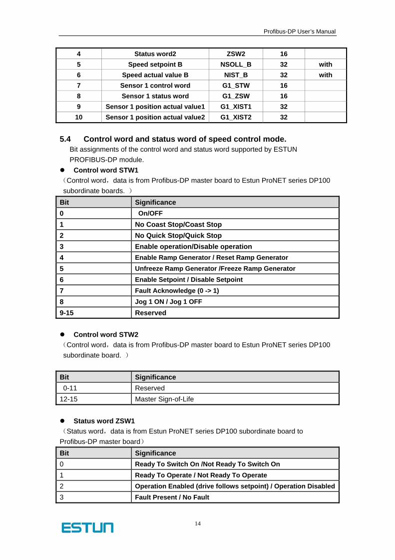
4 Status word2 ZSW2 16 5 Speed setpoint B NSOLL_B 32 with 6 Speed actual value B NIST_B 32 with 7 Sensor 1 control word G1_STW 16 8 Sensor 1 status word G1_ZSW 16 9 Sensor 1 position actual value1 G1_XIST1 32 10 Sensor 1 position actual value2 G1_XIST2 32
5.4 Control word and status word of speed control mode.
Bit assignments of the control word and status word supported by ESTUN PROFIBUS-DP module.
Control word STW1 (Control word,data is from Profibus-DP master board to Estun ProNET series DP100 subordinate boards. )
Bit Significance 0 On/OFF 1 No Coast Stop/Coast Stop 2 No Quick Stop/Quick Stop 3 Enable operation/Disable operation 4 Enable Ramp Generator / Reset Ramp Generator 5 Unfreeze Ramp Generator /Freeze Ramp Generator 6 Enable Setpoint / Disable Setpoint 7 Fault Acknowledge (0 -> 1) 8 Jog 1 ON / Jog 1 OFF 9-15 Reserved
Control word STW2 (Control word,data is from Profibus-DP master board to Estun ProNET series DP100 subordinate board. )
Bit Significance 0-11 Reserved
12-15 Master Sign-of-Life
Status word ZSW1 (Status word,data is from Estun ProNET series DP100 subordinate board to Profibus-DP master board) Bit Significance 0 Ready To Switch On /Not Ready To Switch On 1 Ready To Operate / Not Ready To Operate 2 Operation Enabled (drive follows setpoint) / Operation Disabled3 Fault Present / No Fault

Profibus-DP User’s Manual
15
4 Coast Stop Not Activated / Coast Stop Activated 5 Quick Stop Not Activated / Quick Stop Activated 6 Switching On Inhibited / Switching On Not Inhibited 7 Warning Present / No Warning 8 Speed Error Within Tolerance Range /
Speed Error Out Of Tolerance Range 9 Control Requested / No Control Requested 10 f Or n Reached Or Exceeded /f Or n Not Reached 11-15 Reserved
Status word ZSW2 (Status word,data is from Estun ProNET series DP100 subordinate board to Profibus-DP master board) Bit Significance 0-11 Reserved
12-15 Master Sign-of-Life 5.5 Synchronization
Periodical mode
TDP:Bus period
At the synchronization mode, time between two neighboring GC (global command) should be identical to each other. All the subordinate boards could receive GC to achieve the precise synchronized control of the servo drives.
5.6 Note for communication When Profibus-DPV0、Profibus-DPV1 are used to communicate, the parameter Pn006.0 should be set as 1 in ProNet servo drive. When Profibus-DPV2 is used, Pn006.0 should be set as 2.

Profibus-DP User’s Manual
16
Chapter 6:The introduction of GSD file and parameter
setting
GSD file, as one kind of character file, is applied to detect PROFIBUS-DP devices (master station or subordinate station). It contains all necessary information for configuring a DP subordinate station in a standard DP master station. GSD file basically contains vendor profiles, supportable communication speed, timing information, supportable features and accessories, available I/O information. GSD file is the basic structure for the master station’s parameter record. ;****** GSD-Datei for VPC3 application ************************************** ;* Vendor: ESTUN ;* Function: for Estun ProNet ;*history ;*2008.08.12[V2.00] Version #Profibus_DP ;***************************************************************************************** ;General DP Keywords ;***************************************************************************************** GSD_Revision = 5 Vendor_Name = "ESTUN" Model_Name = "ESTUNV2" Revision = "2.00" Ident_Number = 0xAFFE Protocol_Ident = 0 Station_Type = 0 FMS_supp = 0 Hardware_Release = "V1.00" Software_Release = "V1.00" Redundancy = 0 Repeater_Ctrl_Sig = 2 24V_Pins = 0 ;**************************************************************************************************** ; Supported baudrates ;**************************************************************************************************** 9.6_supp = 1

Profibus-DP User’s Manual
17
19.2_supp = 1 45.45_supp = 1 93.75_supp = 1 187.5_supp = 1 500_supp = 1 1.5M_supp = 1 3M_supp = 1 6M_supp = 1 12M_supp = 1 MaxTsdr_9.6=15 MaxTsdr_19.2=15 MaxTsdr_45.45=15 MaxTsdr_93.75=15 MaxTsdr_187.5=15 MaxTsdr_500=15 MaxTsdr_1.5M=20 MaxTsdr_3M=35 MaxTsdr_6M=50 MaxTsdr_12M=95 ;*********************************************************************************************** ;Slave specific values ;*********************************************************************************************** ;OrderNumber="PA006300, PA7062" Slave_Family = 0@VPC3+ Implementation_Type = "VPC3+C" Info_Text="ESTUN: ProNet_EDB-50AM servo drive PROFIBUS-DPV2" Freeze_Mode_supp=1 Sync_Mode_supp=1 Fail_Safe=1 Auto_Baud_supp=1 Set_Slave_Add_supp=0 Min_Slave_Intervall=1 Modular_Station=1 Max_Module=1 Modul_Offset=1 Max_Input_Len=26 Max_Output_Len=18

Profibus-DP User’s Manual
18
Max_Data_Len=44 Max_Diag_Data_Len=6 ;**************************************************************************************************** ; User-Prm-Data ;*************************************************************************************************** Max_User_Prm_Data_Len = 31 Ext_User_Prm_Data_Const(0)= 0x00,0x00,0x00 ;**************************************************************************************************** ;Module-Definition-List ;*************************************************************************************************** Module="PKW + PZD " 0xC1,0xC8,0xCC,0x01 1 ;Ext_Module_Prm_Data_Len=9 ;Ext_User_Prm_Data_Const(0)=0x09,0x01,0x00,0x00,0x01,0xFF,0xFF,0x00,0x00 EndModule ;Module="PZD " 0xC1,0xC4,0xC8,0x02 ;Ext_Module_Prm_Data_Len=9 ;Ext_User_Prm_Data_Const(0)=0x00,0x01,0x00,0x00,0x01,0xFF,0xFF,0x00,0x00 ;2 ;EndModule ;********************************************************************************************** ;DPV1 KEY WORDS ;********************************************************************************************** DPV1_Slave = 1 C1_Read_Write_supp = 1 C2_Read_Write_supp = 1 C1_Max_Data_Len = 240 C2_Max_Data_Len = 240 C1_Response_Timeout = 300 C2_Response_Timeout = 300 C1_Read_Write_required = 0 C2_Read_Write_required = 0 C2_Max_Count_Channels = 3 Max_Initiate_PDU_Length = 52 DPV1_Data_Types = 0 WD_Base_1ms_supp = 1 Check_Cfg_Mode = 0

Profibus-DP User’s Manual
19
Publisher_supp = 1 Diagnostic_Alarm_supp = 0 Process_Alarm_supp = 0 Alarm_Type_Mode_supp = 0 ;Ident_Maintenance_supp = 1 ;I&M fuctions supported ;*************************************************************************************************** Prm_Block_Structure_supp = 1 Prm_Block_Structure_req = 0 ; isochronous mode Isochron_Mode_supp = 1 Isochron_Mode_required = 0 TBASE_DP = 1500 ; * 1/12 us = 125 us TDP_MIN = 8 ; * TBASE_DP = 1000 us TDP_MAX = 256 ; * TBASE_DP T_PLL_W_MAX = 12 ; * 1/12 us = 1 us TBASE_IO = 1500 ; * 1/12 us = 125 us TI_MIN = 1 ; * TBASE_IO TO_MIN = 1 ; * TBASE_IO

Profibus-DP User’s Manual
20
Chapter 7:LED instruction and troubleshooting
7.1 LED instruction There are two LEDs, ALM LED and COMM LED in Profibus-DP module to indicate the status of PROFIBUS-DP module. It will be reset after power off and then power on. Yellow and red lights will flash simultaneously.
COMM LED COMM status ALM status Function
description Solution
Dark Dark Module out of work
1. power off to check connection between the drive and the module 2. Power off again and reactivate
Yellow light flashes
Red light flashes and then turns into green
Module reactivated
Yellow light is dark
Random Out of access to PROFIBUS
1.check the network connection 2.check if PROFIBUS master station is operating normally. 3. check the address button
4. Power off and reactivate Yellow light
flashes Random PROFIBUS
Communication operates normally
Profibus data is exchanging normally
Random Red light is on RAM error 1.Reset 2.Repair
Random Red light flashes DPRAM data exchange
error
1. Check if the power supply is OK. 2. check connection between the drive and the module 3. Power off again and reactivate
Random Green light flashes DPRAM data exchanges normally.
Communication operates normally.

Profibus-DP User’s Manual
21
Chapter 8:Parameter mode/Object dictionary
Every parameter could be considered as a variable. Parameter could be seen as the name in PROFIBUS system, which is the same as the definition of the object in CANopen or other system. There is a description list about the parameters in the drive to configure and process the parameter. Chapters below will include the information of these parameters and brief introduction of their structure. Exchange information in PROFIBUS PZD standard message is called signal. They are as same as parameters. Only a few of parameters could be transmitted periodically. They are listed in the signal list. You could refer to this list for more information about the parameters. Detailed information of one parameters contains … � Identical parameter number.(PNU) � Value of the parameter(PWE) � Description(PBE) � Optional: backup information. All the parameters are organized in a parameter list and each parameter obtains an identical parameter number which is called PNU.
PNU range Description
0 ~ 686 Parameter for servo drive(Please refer to servo drive user
‘s manual for detailed information)
687 ~ 899 Parameter for servo drive(Reserved)
900 ~ 999 General parameter supplied by servo drive manufacturer
1000 ~ 59999 Parameter for servo drive(for extended use)
60000 ~ 65535 General parameter supplied by servo drive
manufacturer(for extended use and reserved currently)
Parameter could be a simple variable( sole variable) or complex variable(variable array). When the variable array is used, the array member variable uses index to identify itself. 8.1 Parameter structure Please refer to parameter description chapter for the total parameter list Pn1400 – control word -> PNU Number and description
Unit: - -> The unit of the parameter Read/Write type: R/W -> R/W means Read/Write and RO means read
only Data type: Uint16 -> Please refer to the data type part as below Range of value: 0x0 ... 0xFFFF -> lower limit and upper limit Defalut value: 0x0 -> default value If effective after power off:yes ->whether or
not the power should be shutdown and then on to activate the revised parameter.

Profibus-DP User’s Manual
22
8.2 Datatype All the data types used in the drives are as below …
Data type Brief description range
Bit Binary parameter 0000Bit … 1111Bit
Hex Hex parameter 0000Hex … FFFFHex
Int16 Signed hex parameter -32768 … +32767
Uint16 Unsigned hex parameter 0 … 65535
Int32 Signed 32-bit parameter -2147483648 …+2147483647
Uint32 Signed 32-bit parameter 0 … 4294967295
8.3 Parameter objective dictionary List below shows all the parameters used in our servo drive. Please refer to chapter nine Parameter descriptions.
PNU Description Unit Read/Write
type
Data
type Range of value Default
0 - R/W Bit 0000 ~ 1111 0
。。。 - R/W 。。。 。。。 。。。
4 - R/W Hex 0x0000~0x3435 0x0000
。。。 - R/W 。。。 。。。 。。。
686
Please refer to the user’s
manual or parameter
descriptions.
rpm R/W Uint16 0 ~ 6000 30
687 ~ 910 Reserved
911 PPO type,3 for our drive - RO Uint32 - 3
912 ~ 917 Reserved
918 Servo drive axis address - RO Uint32 0 ~ 126 -
919 ~ 962 Reserved
963 Communicate baud rate - RO Uint32 - -
964 ~ 1009 Reserved
1010 present speed reference 0.1rpm R/W Int32 -30000 ~ 30000 0
1011 actual speed of servo
motor 0.1rpm RO Int32 -30000 ~ 30000 0
1012 ~ 1399 Reserved
1400 STW1 - R/W Uint16 0x0 ~ 0xFFFF 0
1401 ~ 1402 Reserved
1403 ZSW1 - RO Uint16 0x0 ~ 0xFFFF 0
1404 ~ 1405 Reserved
1406 Encoder feedback 1 pulse RO Uint32 0 ~
0xFFFFFFFF 0
1407 ~ 1599 Reserved
1600 Present input signal - R/W Uint16 0x0 ~ 0x00FF 0
1601 Torque of the motor 0.1Nm RO Int16 0
1602 ~
65535 Remain Unused

Profibus-DP User’s Manual
23
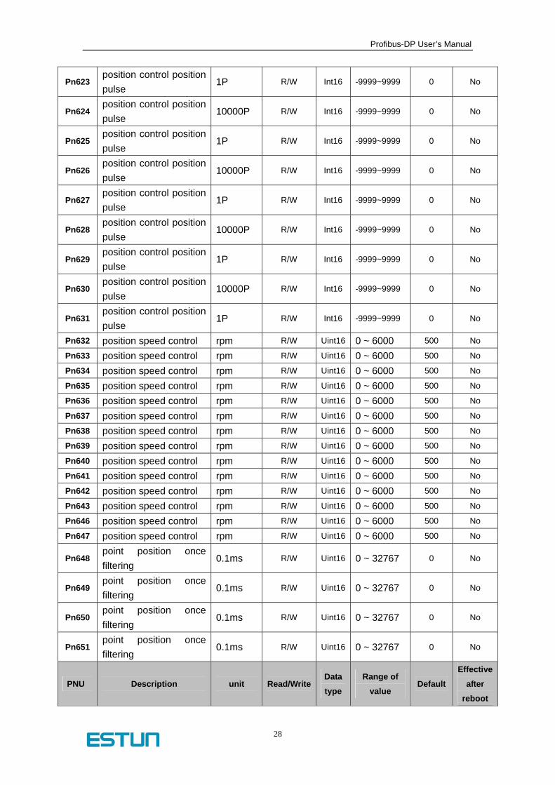
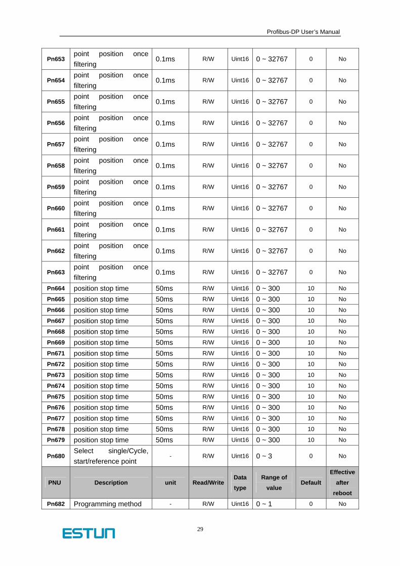
Chapter 9: Parameter description
PNU Description unit Read/WriteData
type
Range of
value Default
Effective
after
reboot
Pn000
Pn000.0: parameter servo ON [0] Outside S-ON valid [1] Outside S-ON invalid, motor excitation signal turned on automatically after S-RDY output Pn000.1 Forward direction input prohibited [0] Outside P-OT valid, it moves according to the Pn004.0 setting time sequence when it reaches the travel limit. [1] Outside P-PT invalid. Pn000.2 Reversed direction input prohibited [0] Outside N-OT valid, it moves according to the Pn004.0 setting time sequence when it reach the travel limit. [1] Outside P-PT invalid. Pn000.3 Momentary power off alarm output [0] No alarm in one momentary power off circle [1] Alarm in one momentary power off circle.
- R/W Bit 0000 ~ 1111 0 yes
PNU Description unit Read/Write Data
type
Range of
value Default
Effective
after
reboot
Pn101 Load rigid selection - R/W Uint16 0 ~ 15 5 No
Pn102 Speed loop gain Hz R/W Uint16 1 ~ 2500 160 No
Pn103 Speed loop integral time 0.1ms R/W Uint16 1 ~ 4096 200 No

Profibus-DP User’s Manual
24
Pn104 position loop gain Hz R/W Uint16 0 ~ 1000 40 No
Pn105 Torque instruction filter constant
0.1ms R/W Uint16 0 ~ 250 4 No
Pn106 Load inertia percentage - R/W Uint16 0 ~ 20000 0 No
Pn107 The second speed loop gain
Hz R/W Uint16 1 ~ 2500 16 No
Pn108 The second speed loop integral time constant
0.1ms R/W Uint16 1 ~ 4096 20 No
Pn109 The second loop gain Hz R/W Uint16 0 ~ 1000 40 No
Pn110 The second torque instruction filter constant
0.1ms R/W Uint16 0 ~ 250 150 No
Pn111 Speed offset rpm R/W Uint16 0 ~ 300 0 No
Pn112 Feed forward % R/W Uint16 0 ~ 100 0 No
Pn113 Feed forward filtering 0.1ms R/W Uint16 0 ~ 640 0 No
Pn114 Torque feed forward % R/W Uint16 0 ~ 100 0 No
Pn115 Torque feed forward filtering
0.1ms R/W Uint16 0 ~ 640 0 No
Pn116
P/PI switch conditions 0: torque instruction percentage 1: offset counter value 2: setting acceleration value 3: setting speed value 4: fixed PI
- R/W Uint16 0 ~ 4 0 Yes
Pn117 Torque switch threshold - R/W Uint16 0 ~ 300 200 No
Pn119 Setting acceleration switch threshold
10rpm/s R/W Uint16 0 ~ 10000 0 No
Pn120 Setting speed switch threshold
rpm R/W Uint16 0 ~ 3000 0 No
Pn122 switch delay time 0.1ms R/W Uint16 0 ~ 20000 0 No
Pn123 Switch threshold level - R/W Uint16 0 ~ 20000 0 No
Pn124 Speed gain integral switch time
0.1ms R/W Uint16 0 ~ 20000 0 No
Pn125 Position gain switch time 0.1ms R/W Uint16 0 ~ 20000 0 No
Pn126 Hysterics switch - R/W Uint16 0 ~ 20000 0 No
PNU Description unit Read/WriteData
type
Range of
value Default
Effective
after
reboot

Profibus-DP User’s Manual
25
Pn128
Real time adjustment speed gain increase relationship
0 = Kv : Kp-->1
1 = Kv : Kp-->2
2 = Kv : Kp-->3
3 = Kv : Kp-->4
- R/W Uint16 0 ~ 3 3 No
Pn129 Low speed verifying constant
- R/W Uint16 0 ~ 30000 0 No
Pn200 PG frequency division Puls R/W Uint16 16 ~ 16384 16384 yes
Pn201 The first electrical gear numerator
- R/W Uint16 1 ~ 65535 1 yes
Pn202 Electrical gear denominator
- R/W Uint16 1 ~ 65535 1 yes
Pn203 The second electrical gear numerator
- R/W Uint16 1 ~ 65535 1 yes
Pn204 Position instruction filtering time constant
0.1ms R/W Uint16 0 ~ 32767 0 No
Pn205 Selection of position instruction filtering mode
- R/W Uint16 0 ~ 1 0 yes
Pn300 Speed instruction input gain
rpm/v R/W Uint16 0 ~ 3000 150 No
Pn301 Inside speed 1 rpm R/W Uint16 0 ~ 6000 100 No
Pn302 Inside speed 2 rpm R/W Uint16 0 ~ 6000 200 No
Pn303 Inside speed 3 rpm R/W Uint16 0 ~ 6000 300 No
Pn304 Parameter speed rpm R/W Uint16 0 ~ 6000 300 No
Pn305 JOG speed rpm R/W Uint16 0 ~ 6000 300 No
Pn306 Soft reset acceleration time
ms R/W Uint16 0 ~ 3000 0 No
Pn307 Soft reset deceleration time
ms R/W Uint16 0 ~ 3000 0 No
Pn308 Speed filtering time constant
ms R/W Uint16 0 ~ 3000 0 No
Pn309 S curve rising time ms R/W Uint16 0 ~ 3000 0 No
Pn311 Selection of S shape - R/W Uint16 0 ~ 2 0 No
Pn400 Torque instruction gain 0.1V/100% R/W Uint16 33~100 33 No
Pn401 forward rotation torque inside limit
% R/W Uint16 0~300 300 No
PNU Description unit Read/WriteData
type
Range of
value Default
Effective
after
reboot

Profibus-DP User’s Manual
26
Pn403 Forward rotation outside torque limit
% R/W Uint16 0~300 100 No
Pn404 Backward outside torque limit
% R/W Uint16 0~300 100 No
Pn405 Plug braking torque limit % R/W Uint16 0~300 300 No
Pn406 Torque control speed limit
rpm R/W Uint16 0~6000 1500 No
Pn500 Position error Puls R/W Uint16 0~5000 10 No
Pn501 Same speed error rpm R/W Uint16 0~100 10 No
Pn502 Zero clamping rotating speed
rpm R/W Uint16 0~3000 10 No
Pn503 Rotation inspection speed TGON
rpm R/W Uint16 0~3000 20 No
Pn504 Offset counter overflow alarm
256Puls R/W Uint16 1~32767 1024 No
Pn505 Servo-on waiting time ms R/W Uint16 0~2000 200 No
Pn506 Basic waiting course 10ms R/W Uint16 0~500 0 No
Pn507 Braking waiting speed rpm R/W Uint16 10~100 10 No
Pn508 Braking waiting time 10ms R/W Uint16 10~100 10 No
Pn509 Match the port to hex signals. Every 4 bit for one port
- R/W Hex 0~0x9999 0x3210 No
Pn510 Match the port to hex signals. Every 4 bit for one port
- R/W Hex 0~0x9999 0x7654 No
Pn511
Input signal allocation hex00:1CN78 hex01:1CN12 hex02:1CN56 [ 0:COIN,1:TGON, 2:S-RDY,3:CLT,4:BRK]
- R/W Hex 0~0x0444 0x0210 No
Pn512 Bus_io_LEn - R/W Bit 0000~1111 0 No
Pn513 Bus_io_HEn - R/W Bit 0000~1111 0 No
Pn515 Internal signal filtering 0.2ms R/W Uint16 0 ~ 3 1 No
Pn516 negate the input port singal
- R/W Uint16 0000~1111 0 No
Pn517 negate the input port signal
- R/W Uint16 0000~1111 0 No
Pn518 DB time ms R/W Uint16 50 ~ 2000 125 No
PNU Description unit Read/WriteData
type
Range of
value Default
Effective
after
reboot

Profibus-DP User’s Manual
27
Pn600 Demonstrated position pulse
10000P R/W Int16 -9999~9999 0 No
Pn601 Demonstrated position pulse
1P R/W Int16 -9999~9999 0 No
Pn602 position control position pulse
10000P R/W Int16 -9999~9999 0 No
Pn603 position control position pulse
1P R/W Int16 -9999~9999 0 No
Pn605 position control position pulse
1P R/W Int16 -9999~9999 0 No
Pn606 position control position pulse
10000P R/W Int16 -9999~9999 0 No
Pn607 position control position pulse
1P R/W Int16 -9999~9999 0 No
Pn608 position control position pulse
10000P R/W Int16 -9999~9999 0 No
Pn609 position control position pulse
1P R/W Int16 -9999~9999 0 No
Pn610 position control position pulse
10000P R/W Int16 -9999~9999 0 No
Pn611 position control position pulse
1P R/W Int16 -9999~9999 0 No
Pn612 position control position pulse
10000P R/W Int16 -9999~9999 0 No
Pn613 position control position pulse
1P R/W Int16 -9999~9999 0 No
Pn614 position control position pulse
10000P R/W Int16 -9999~9999 0 No
Pn615 position control position pulse
1P R/W Int16 -9999~9999 0 No
Pn616 position control position pulse
10000P R/W Int16 -9999~9999 0 No
Pn618 position control position pulse
10000P R/W Int16 -9999~9999 0 No
Pn619 position control position pulse
1P R/W Int16 -9999~9999 0 No
Pn620 position control position pulse
10000P R/W Int16 -9999~9999 0 No
Pn621 position control position pulse
1P R/W Int16 -9999~9999 0 No
PNU Description unit Read/WriteData
type
Range of
value Default
Effective
after
reboot
Profibus-DP User’s Manual
28
Pn623 position control position pulse
1P R/W Int16 -9999~9999 0 No
Pn624 position control position pulse
10000P R/W Int16 -9999~9999 0 No
Pn625 position control position pulse
1P R/W Int16 -9999~9999 0 No
Pn626 position control position pulse
10000P R/W Int16 -9999~9999 0 No
Pn627 position control position pulse
1P R/W Int16 -9999~9999 0 No
Pn628 position control position pulse
10000P R/W Int16 -9999~9999 0 No
Pn629 position control position pulse
1P R/W Int16 -9999~9999 0 No
Pn630 position control position pulse
10000P R/W Int16 -9999~9999 0 No
Pn631 position control position pulse
1P R/W Int16 -9999~9999 0 No
Pn632 position speed control rpm R/W Uint16 0 ~ 6000 500 No
Pn633 position speed control rpm R/W Uint16 0 ~ 6000 500 No
Pn634 position speed control rpm R/W Uint16 0 ~ 6000 500 No
Pn635 position speed control rpm R/W Uint16 0 ~ 6000 500 No
Pn636 position speed control rpm R/W Uint16 0 ~ 6000 500 No
Pn637 position speed control rpm R/W Uint16 0 ~ 6000 500 No
Pn638 position speed control rpm R/W Uint16 0 ~ 6000 500 No
Pn639 position speed control rpm R/W Uint16 0 ~ 6000 500 No
Pn640 position speed control rpm R/W Uint16 0 ~ 6000 500 No
Pn641 position speed control rpm R/W Uint16 0 ~ 6000 500 No
Pn642 position speed control rpm R/W Uint16 0 ~ 6000 500 No
Pn643 position speed control rpm R/W Uint16 0 ~ 6000 500 No
Pn646 position speed control rpm R/W Uint16 0 ~ 6000 500 No
Pn647 position speed control rpm R/W Uint16 0 ~ 6000 500 No
Pn648 point position once filtering
0.1ms R/W Uint16 0 ~ 32767 0 No
Pn649 point position once filtering
0.1ms R/W Uint16 0 ~ 32767 0 No
Pn650 point position once filtering
0.1ms R/W Uint16 0 ~ 32767 0 No
Pn651 point position once filtering
0.1ms R/W Uint16 0 ~ 32767 0 No
PNU Description unit Read/WriteData
type
Range of
value Default
Effective
after
reboot
Profibus-DP User’s Manual
29
Pn653 point position once filtering
0.1ms R/W Uint16 0 ~ 32767 0 No
Pn654 point position once filtering
0.1ms R/W Uint16 0 ~ 32767 0 No
Pn655 point position once filtering
0.1ms R/W Uint16 0 ~ 32767 0 No
Pn656 point position once filtering
0.1ms R/W Uint16 0 ~ 32767 0 No
Pn657 point position once filtering
0.1ms R/W Uint16 0 ~ 32767 0 No
Pn658 point position once filtering
0.1ms R/W Uint16 0 ~ 32767 0 No
Pn659 point position once filtering
0.1ms R/W Uint16 0 ~ 32767 0 No
Pn660 point position once filtering
0.1ms R/W Uint16 0 ~ 32767 0 No
Pn661 point position once filtering
0.1ms R/W Uint16 0 ~ 32767 0 No
Pn662 point position once filtering
0.1ms R/W Uint16 0 ~ 32767 0 No
Pn663 point position once filtering
0.1ms R/W Uint16 0 ~ 32767 0 No
Pn664 position stop time 50ms R/W Uint16 0 ~ 300 10 No
Pn665 position stop time 50ms R/W Uint16 0 ~ 300 10 No
Pn666 position stop time 50ms R/W Uint16 0 ~ 300 10 No
Pn667 position stop time 50ms R/W Uint16 0 ~ 300 10 No
Pn668 position stop time 50ms R/W Uint16 0 ~ 300 10 No
Pn669 position stop time 50ms R/W Uint16 0 ~ 300 10 No
Pn671 position stop time 50ms R/W Uint16 0 ~ 300 10 No
Pn672 position stop time 50ms R/W Uint16 0 ~ 300 10 No
Pn673 position stop time 50ms R/W Uint16 0 ~ 300 10 No
Pn674 position stop time 50ms R/W Uint16 0 ~ 300 10 No
Pn675 position stop time 50ms R/W Uint16 0 ~ 300 10 No
Pn676 position stop time 50ms R/W Uint16 0 ~ 300 10 No
Pn677 position stop time 50ms R/W Uint16 0 ~ 300 10 No
Pn678 position stop time 50ms R/W Uint16 0 ~ 300 10 No
Pn679 position stop time 50ms R/W Uint16 0 ~ 300 10 No
Pn680 Select single/Cycle, start/reference point
- R/W Uint16 0 ~ 3 0 No
PNU Description unit Read/WriteData
type
Range of
value Default
Effective
after
reboot
Pn682 Programming method - R/W Uint16 0 ~ 1 0 No

Profibus-DP User’s Manual
30
Pn683 programming start step - R/W Uint16 0 ~ 15 0 No
Pn684 programming stop step - R/W Uint16 0 ~ 15 1 No
Pn685 Search travel speed rpm R/W Uint16 0 ~ 3000 1500 No
Pn901 Soft version of module
board - RO Uint16 - No
Pn911 PPO type,3 for our servo
drive - RO Uint16 - 3 No
Pn918 axis address of servo drive - RO Uint16 - - No
Pn963 Communication baud rate - RO Uint16 - No
Pn1010 present speed reference 0.1rpm R/W Int32-30000 ~
30000 0 No
Pn1011 actual motor speed 0.1rpm RO Int32-30000 ~
30000 0 No
Pn1400 Control word STW1 - R/W Uint160x0 ~
0xFFFF 0 No
Pn1403 Control word ZSW1 - RO Uint160x0 ~
0xFFFF 0 No
Pn1406 Encoder feedback 1pulse RO Uint320 ~
0xFFFFFFFF 0 No
Pn1600 Present input signal - R/W Uint160x0 ~
0x00FF 0 No
Pn1601 Motor torque 0.1Nm RO Int16 0 No