RS-232/485 - Ethernet converter + serial buffer TCP/IP … · · 2006-03-26RS-232/485 - Ethernet...
24
PortStore2 RS-232/485 - Ethernet converter + serial buffer TCP/IP Server or Client/Server mode EN 900 577a
Transcript of RS-232/485 - Ethernet converter + serial buffer TCP/IP … · · 2006-03-26RS-232/485 - Ethernet...
PortStore2 RS-232/485 - Ethernet converter + serial buffer TCP/IP Server or Client/Server mode
EN 900 577a

PortStore2 – CDR/SMDR PBX accounting data buffer HW group
March 2006 page 2 / 24 www.HW-group.com
PortStore2 – CDR/SMDR PBX accounting data buffer HW group
March 2006 page 3 / 24 www.HW-group.com
Table of contents The complete shipment includes:....................................................................................2
Table of contents.............................................................................................................3
Basic features .................................................................................................................4
Technical parameters......................................................................................................5
CONNECTORS DESCRIPTION ...............................................................................................6
QUICK SETUP..................................................................................................................7
IP address configuration .................................................................................................7 Configuration using TCP Setup.......................................................................................8 Configuration using RS-232 terminal ..............................................................................8
System topology..............................................................................................................9
HW VSP - VIRTUAL SERIAL PORT ...................................................................................10
PORTSTORE2 SETUP –CONFIGURATION PARAMETERS DESCRIPTION....................................12
Factory defaults.............................................................................................................12
Network parameters......................................................................................................13
TCP and UDP parameters ............................................................................................14
Serial port parameters...................................................................................................15
Other parameters..........................................................................................................16
UDP/IP mode settings...................................................................................................17
Practical examples of the configuration.........................................................................18 2x PortStore2 devices connected to each other............................................................18
Free application software ..............................................................................................19
PORTSTORE2 IN PRACTICE ..............................................................................................20
Application hints ............................................................................................................20 2048 kB buffer...............................................................................................................20 Network Virtual Terminal...............................................................................................20 Extension of the connection timeout .............................................................................20
Typical applications.......................................................................................................21
BASIC TYPES OF COMMUNICATION ....................................................................................22
Mechanical parameters.................................................................................................23 Optional accessories for mechanical attachment..........................................................23
Ordering number ....................................................... Chyba! Záložka není definována. Distributors list .......................................................... Chyba! Záložka není definována. Contact us.....................................................................................................................24
PortStore2 – CDR/SMDR PBX accounting data buffer HW group
March 2006 page 4 / 24 www.HW-group.com
PortStore2 RS-232/485 - CDR/SMDR PBX accounting data buffer
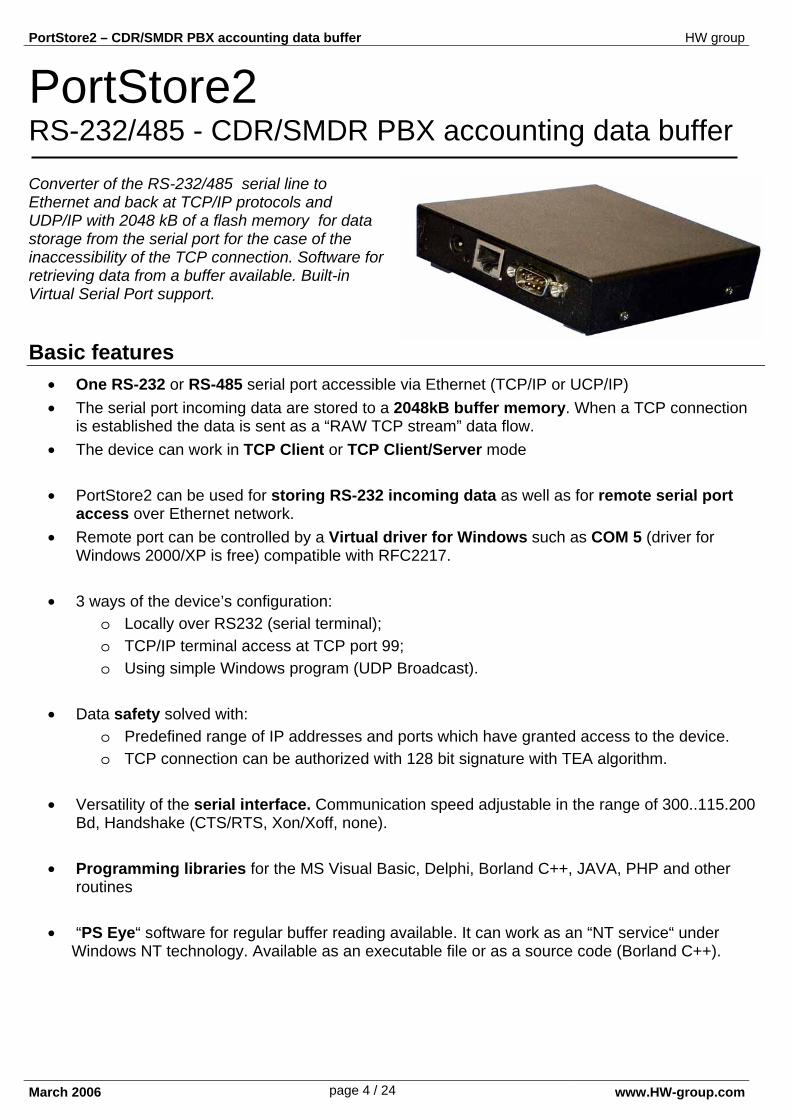
Converter of the RS-232/485 serial line to Ethernet and back at TCP/IP protocols and UDP/IP with 2048 kB of a flash memory for data storage from the serial port for the case of the inaccessibility of the TCP connection. Software for retrieving data from a buffer available. Built-in Virtual Serial Port support. Basic features
• One RS-232 or RS-485 serial port accessible via Ethernet (TCP/IP or UCP/IP) • The serial port incoming data are stored to a 2048kB buffer memory. When a TCP connection
is established the data is sent as a “RAW TCP stream” data flow. • The device can work in TCP Client or TCP Client/Server mode • PortStore2 can be used for storing RS-232 incoming data as well as for remote serial port
access over Ethernet network. • Remote port can be controlled by a Virtual driver for Windows such as COM 5 (driver for
Windows 2000/XP is free) compatible with RFC2217. • 3 ways of the device’s configuration:
o Locally over RS232 (serial terminal); o TCP/IP terminal access at TCP port 99; o Using simple Windows program (UDP Broadcast).
• Data safety solved with:
o Predefined range of IP addresses and ports which have granted access to the device. o TCP connection can be authorized with 128 bit signature with TEA algorithm.
• Versatility of the serial interface. Communication speed adjustable in the range of 300..115.200 Bd, Handshake (CTS/RTS, Xon/Xoff, none).
• Programming libraries for the MS Visual Basic, Delphi, Borland C++, JAVA, PHP and other
routines • “PS Eye“ software for regular buffer reading available. It can work as an “NT service“ under
Windows NT technology. Available as an executable file or as a source code (Borland C++).
PortStore2 – CDR/SMDR PBX accounting data buffer HW group
March 2006 page 5 / 24 www.HW-group.com
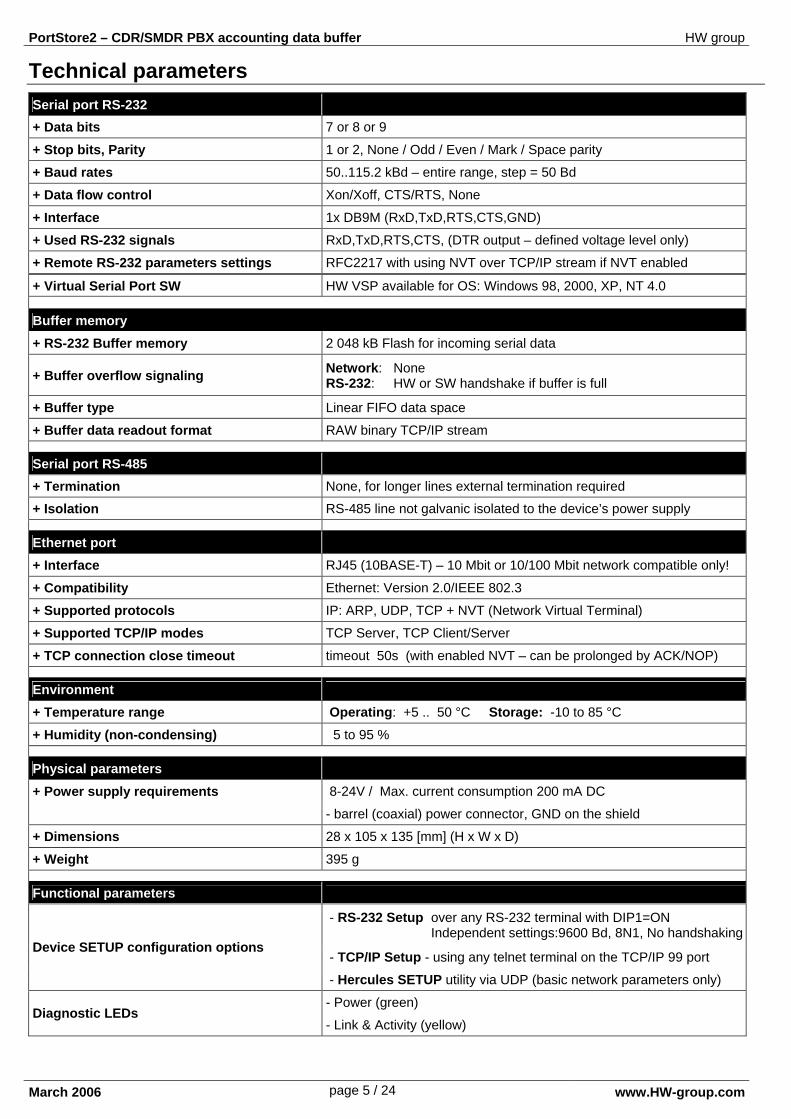
Technical parameters Serial port RS-232
+ Data bits 7 or 8 or 9
+ Stop bits, Parity 1 or 2, None / Odd / Even / Mark / Space parity
+ Baud rates 50..115.2 kBd – entire range, step = 50 Bd
+ Data flow control Xon/Xoff, CTS/RTS, None
+ Interface 1x DB9M (RxD,TxD,RTS,CTS,GND)
+ Used RS-232 signals RxD,TxD,RTS,CTS, (DTR output – defined voltage level only)
+ Remote RS-232 parameters settings RFC2217 with using NVT over TCP/IP stream if NVT enabled
+ Virtual Serial Port SW HW VSP available for OS: Windows 98, 2000, XP, NT 4.0
Buffer memory
+ RS-232 Buffer memory 2 048 kB Flash for incoming serial data
+ Buffer overflow signaling Network: None RS-232: HW or SW handshake if buffer is full
+ Buffer type Linear FIFO data space
+ Buffer data readout format RAW binary TCP/IP stream
Serial port RS-485
+ Termination None, for longer lines external termination required
+ Isolation RS-485 line not galvanic isolated to the device’s power supply
Ethernet port
+ Interface RJ45 (10BASE-T) – 10 Mbit or 10/100 Mbit network compatible only!
+ Compatibility Ethernet: Version 2.0/IEEE 802.3
+ Supported protocols IP: ARP, UDP, TCP + NVT (Network Virtual Terminal)
+ Supported TCP/IP modes TCP Server, TCP Client/Server
+ TCP connection close timeout timeout 50s (with enabled NVT – can be prolonged by ACK/NOP)
Environment
+ Temperature range Operating: +5 .. 50 °C Storage: -10 to 85 °C
+ Humidity (non-condensing) 5 to 95 %
Physical parameters
+ Power supply requirements 8-24V / Max. current consumption 200 mA DC
- barrel (coaxial) power connector, GND on the shield
+ Dimensions 28 x 105 x 135 [mm] (H x W x D)
+ Weight 395 g
Functional parameters
- RS-232 Setup over any RS-232 terminal with DIP1=ON Independent settings:9600 Bd, 8N1, No handshaking
- TCP/IP Setup - using any telnet terminal on the TCP/IP 99 port Device SETUP configuration options
- Hercules SETUP utility via UDP (basic network parameters only)
- Power (green) Diagnostic LEDs
- Link & Activity (yellow)
PortStore2 – CDR/SMDR PBX accounting data buffer HW group
March 2006 page 6 / 24 www.HW-group.com
Ethe
rnet
PW
RC
AN
NO
N 9
M
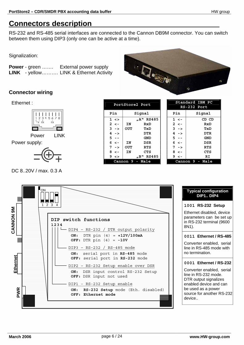
Connectors description RS-232 and RS-485 serial interfaces are connected to the Cannon DB9M connector. You can switch between them using DIP3 (only one can be active at a time). Signalization: Power - green ……. External power supply LINK - yellow………. LINK & Ethernet Activity
Connector wiring
PortStore2 Port
Pin Signal
1 <> „A“ RS485 2 <- IN RxD 3 -> OUT TxD 4 -> DTR 5 -- GND 6 <- IN DSR 7 -> OUT RTS 8 <- IN CTS 9 <> „B“ RS485
Cannon 9 - Male
Standard IBM PC RS-232 Port
Pin Signal
1 <- CD CD 2 <- RxD 3 -> TxD 4 -> DTR 5 -- GND 6 <- DSR 7 -> RTS 8 <- CTS 9 <- RI
Cannon 9 - Male
Typical configuration DIP1.. DIP4
1001 RS-232 Setup
Ethernet disabled, device parameters can be set up in RS-232 terminal (9600 8N1).
0011 Ethernet / RS-485
Converter enabled, serial line in RS-485 mode with no termination.
0001 Ethernet / RS-232
Converter enabled, serial line in RS-232 mode. DTR output signalizes enabled device and can be used as a power source for another RS-232 device..
Ethernet : Power supply: DC 8..20V / max. 0.3 A
Power LINK
ON
4 3 2 1
DIP switch functions 1 2 3 4 DIP4 – RS-232 / DTR output polarity
ON: DTR pin (4) = +12V/100mA OFF: DTR pin (4) = -10V
DIP3 – RS-232 / RS-485 mode
ON: serial port in RS-485 mode OFF: serial port in RS-232 mode
DIP2 – RS-232 Setup enable over DSR
ON: DSR input control RS-232 Setup OFF: DSR input not used
DIP1 – RS-232 Setup enable
ON: RS-232 Setup mode (Eth. disabled) OFF: Ethernet mode
PortStore2 – CDR/SMDR PBX accounting data buffer HW group
March 2006 page 7 / 24 www.HW-group.com
Quick SETUP In this chapter you will be shown the way of configuration within 5 minutes. If you experience any problems, please, read the following chapter which describes the setup process step-by-step.
Cable connection • Connect the delivered feeding adaptor.
• Set DIP1 - DIP4 into the OFF position.
• Connect PortStore2 into the Ethernet 10/100 Mbit network.
• Plug the connector of the power adaptor into Portstore2’s power connector.
• The green Power indicator will light up.
• The LINK indicator will light up and go down as the data transfer to the Ethernet fluctuates (Activity signalization).
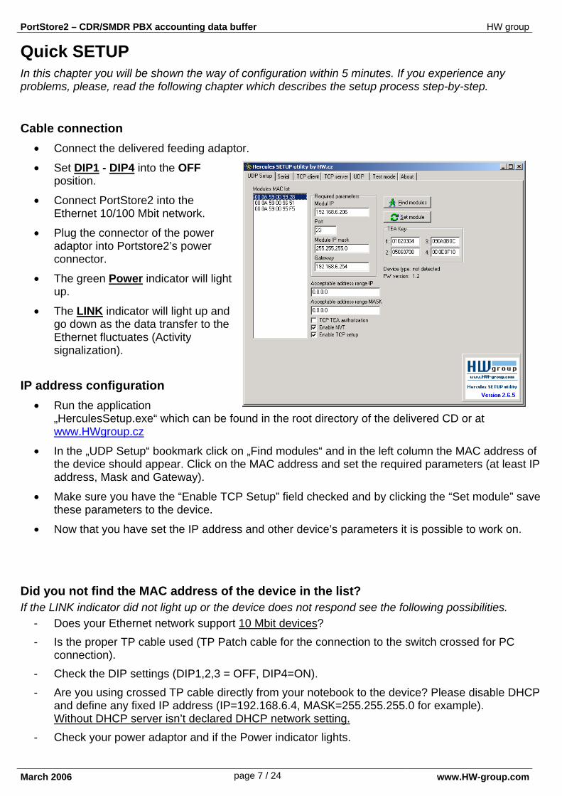
IP address configuration • Run the application
„HerculesSetup.exe“ which can be found in the root directory of the delivered CD or at www.HWgroup.cz
• In the „UDP Setup“ bookmark click on „Find modules“ and in the left column the MAC address of the device should appear. Click on the MAC address and set the required parameters (at least IP address, Mask and Gateway).
• Make sure you have the “Enable TCP Setup” field checked and by clicking the “Set module” save these parameters to the device.
• Now that you have set the IP address and other device’s parameters it is possible to work on.
Did you not find the MAC address of the device in the list? If the LINK indicator did not light up or the device does not respond see the following possibilities.
- Does your Ethernet network support 10 Mbit devices? - Is the proper TP cable used (TP Patch cable for the connection to the switch crossed for PC
connection). - Check the DIP settings (DIP1,2,3 = OFF, DIP4=ON). - Are you using crossed TP cable directly from your notebook to the device? Please disable DHCP
and define any fixed IP address (IP=192.168.6.4, MASK=255.255.255.0 for example). Without DHCP server isn’t declared DHCP network setting.
- Check your power adaptor and if the Power indicator lights.
PortStore2 – CDR/SMDR PBX accounting data buffer HW group
March 2006 page 8 / 24 www.HW-group.com
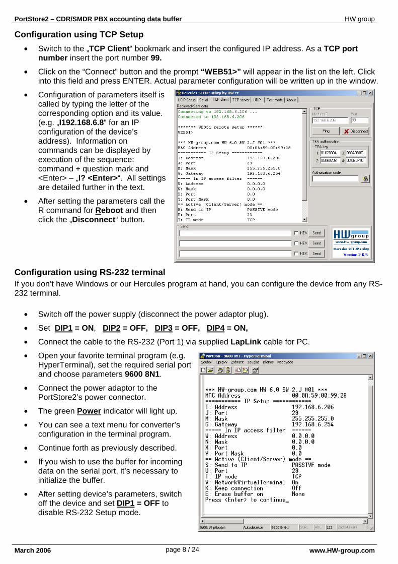
Configuration using TCP Setup • Switch to the „TCP Client“ bookmark and insert the configured IP address. As a TCP port
number insert the port number 99. • Click on the “Connect” button and the prompt “WEB51>” will appear in the list on the left. Click
into this field and press ENTER. Actual parameter configuration will be written up in the window.
• Configuration of parameters itself is called by typing the letter of the corresponding option and its value. (e.g. „I192.168.6.8“ for an IP configuration of the device’s address). Information on commands can be displayed by execution of the sequence: command + question mark and <Enter> – „I? <Enter>“. All settings are detailed further in the text.
• After setting the parameters call the R command for Reboot and then click the „Disconnect“ button.
Configuration using RS-232 terminal If you don’t have Windows or our Hercules program at hand, you can configure the device from any RS-232 terminal.
• Switch off the power supply (disconnect the power adaptor plug).
• Set DIP1 = ON, DIP2 = OFF, DIP3 = OFF, DIP4 = ON, • Connect the cable to the RS-232 (Port 1) via supplied LapLink cable for PC.
• Open your favorite terminal program (e.g. HyperTerminal), set the required serial port and choose parameters 9600 8N1.
• Connect the power adaptor to the PortStore2’s power connector.
• The green Power indicator will light up.
• You can see a text menu for converter’s configuration in the terminal program.
• Continue forth as previously described.
• If you wish to use the buffer for incoming data on the serial port, it’s necessary to initialize the buffer.
• After setting device’s parameters, switch off the device and set DIP1 = OFF to disable RS-232 Setup mode.
PortStore2 – CDR/SMDR PBX accounting data buffer HW group
March 2006 page 9 / 24 www.HW-group.com
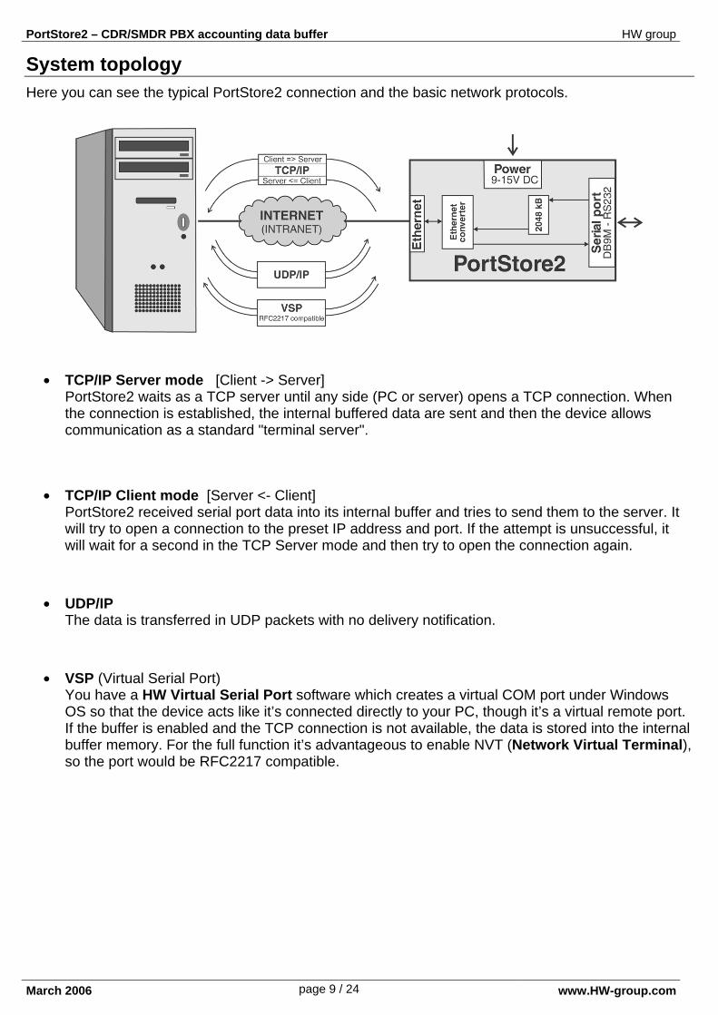
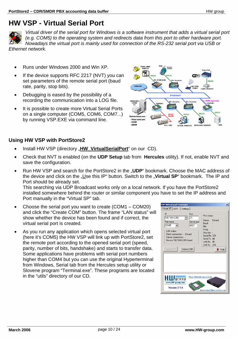
System topology Here you can see the typical PortStore2 connection and the basic network protocols.
• TCP/IP Server mode [Client -> Server] PortStore2 waits as a TCP server until any side (PC or server) opens a TCP connection. When the connection is established, the internal buffered data are sent and then the device allows communication as a standard "terminal server".
• TCP/IP Client mode [Server <- Client] PortStore2 received serial port data into its internal buffer and tries to send them to the server. It will try to open a connection to the preset IP address and port. If the attempt is unsuccessful, it will wait for a second in the TCP Server mode and then try to open the connection again.
• UDP/IP The data is transferred in UDP packets with no delivery notification.
• VSP (Virtual Serial Port) You have a HW Virtual Serial Port software which creates a virtual COM port under Windows OS so that the device acts like it’s connected directly to your PC, though it’s a virtual remote port. If the buffer is enabled and the TCP connection is not available, the data is stored into the internal buffer memory. For the full function it’s advantageous to enable NVT (Network Virtual Terminal), so the port would be RFC2217 compatible.
PortStore2 – CDR/SMDR PBX accounting data buffer HW group
March 2006 page 10 / 24 www.HW-group.com
HW VSP - Virtual Serial Port Virtual driver of the serial port for Windows is a software instrument that adds a virtual serial port (e.g. COM5) to the operating system and redirects data from this port to other hardware port. Nowadays the virtual port is mainly used for connection of the RS-232 serial port via USB or
Ethernet network.
• Runs under Windows 2000 and Win XP.
• If the device supports RFC 2217 (NVT) you can set parameters of the remote serial port (baud rate, parity, stop bits).
• Debugging is eased by the possibility of a recording the communication into a LOG file.
• It is possible to create more Virtual Serial Ports on a single computer (COM5, COM6, COM7...) by running VSP.EXE via command line.
Using HW VSP with PortStore2 • Install HW VSP (directory „HW_VirtualSerialPort“ on our CD).
• Check that NVT is enabled (on the UDP Setup tab from Hercules utility). If not, enable NVT and save the configuration.
• Run HW VSP and search for the PortStore2 in the „UDP“ bookmark. Choose the MAC address of the device and click on the „Use this IP“ button. Switch to the „Virtual SP“ bookmark. The IP and Port should be already set. This searching via UDP Broadcast works only on a local network. If you have the PortStore2 installed somewhere behind the router or similar component you have to set the IP address and Port manually in the “Virtual SP” tab.
• Choose the serial port you want to create (COM1 – COM20) and click the “Create COM” button. The frame “LAN status” will show whether the device has been found and if correct, the virtual serial port is created.
• As you run any application which opens selected virtual port (here it’s COM5) the HW VSP will link up with PortStore2, set the remote port according to the opened serial port (speed, parity, number of bits, handshake) and starts to transfer data. Some applications have problems with serial port numbers higher than COM4 but you can use the original Hyperterminal from Windows, Serial tab from the Hercules setup utility or Slovene program “Terminal.exe”. These programs are located in the “utils” directory of our CD.
PortStore2 – CDR/SMDR PBX accounting data buffer HW group
March 2006 page 11 / 24 www.HW-group.com
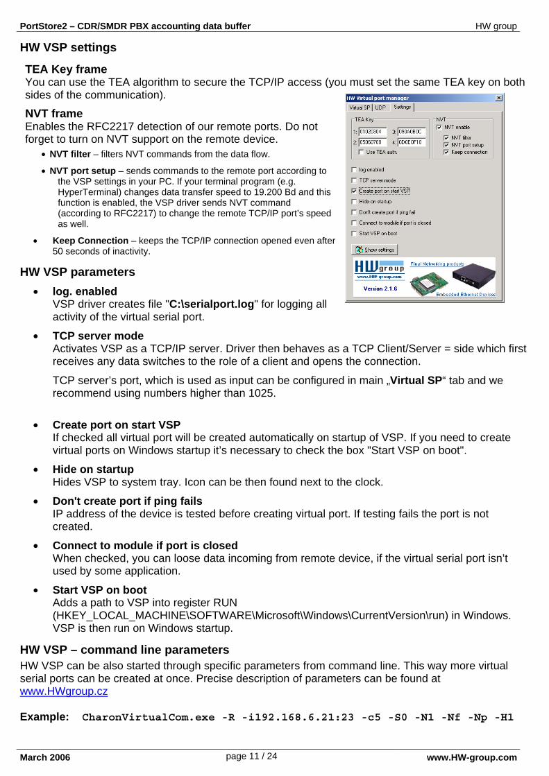
HW VSP settings
TEA Key frame You can use the TEA algorithm to secure the TCP/IP access (you must set the same TEA key on both sides of the communication).
NVT frame Enables the RFC2217 detection of our remote ports. Do not forget to turn on NVT support on the remote device.
• NVT filter – filters NVT commands from the data flow.
• NVT port setup – sends commands to the remote port according to the VSP settings in your PC. If your terminal program (e.g. HyperTerminal) changes data transfer speed to 19.200 Bd and this function is enabled, the VSP driver sends NVT command (according to RFC2217) to change the remote TCP/IP port’s speed as well.
• Keep Connection – keeps the TCP/IP connection opened even after 50 seconds of inactivity.
HW VSP parameters • log. enabled
VSP driver creates file "C:\serialport.log" for logging all activity of the virtual serial port.
• TCP server mode Activates VSP as a TCP/IP server. Driver then behaves as a TCP Client/Server = side which first receives any data switches to the role of a client and opens the connection.
TCP server’s port, which is used as input can be configured in main „Virtual SP“ tab and we recommend using numbers higher than 1025.
• Create port on start VSP If checked all virtual port will be created automatically on startup of VSP. If you need to create virtual ports on Windows startup it’s necessary to check the box "Start VSP on boot".
• Hide on startup Hides VSP to system tray. Icon can be then found next to the clock.
• Don't create port if ping fails IP address of the device is tested before creating virtual port. If testing fails the port is not created.
• Connect to module if port is closed When checked, you can loose data incoming from remote device, if the virtual serial port isn’t used by some application.
• Start VSP on boot Adds a path to VSP into register RUN (HKEY_LOCAL_MACHINE\SOFTWARE\Microsoft\Windows\CurrentVersion\run) in Windows. VSP is then run on Windows startup.
HW VSP – command line parameters HW VSP can be also started through specific parameters from command line. This way more virtual serial ports can be created at once. Precise description of parameters can be found at www.HWgroup.cz Example: CharonVirtualCom.exe -R -i192.168.6.21:23 -c5 -S0 -N1 -Nf -Np -H1
PortStore2 – CDR/SMDR PBX accounting data buffer HW group
March 2006 page 12 / 24 www.HW-group.com
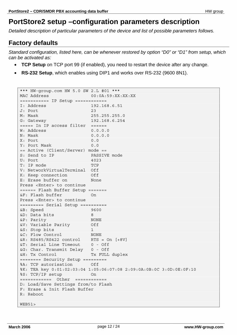
PortStore2 setup –configuration parameters description Detailed description of particular parameters of the device and list of possible parameters follows. Factory defaults Standard configuration, listed here, can be whenever restored by option “D0” or “D1” from setup, which can be activated as:
• TCP Setup on TCP port 99 (if enabled), you need to restart the device after any change.
• RS-232 Setup, which enables using DIP1 and works over RS-232 (9600 8N1). *** HW-group.com HW 5.0 SW 2.L #01 *** MAC Address 00:0A:59:XX:XX:XX =========== IP Setup ============ I: Address 192.168.6.51 J: Port 23 M: Mask 255.255.255.0 G: Gateway 192.168.6.254 ===== In IP access filter ====== W: Address 0.0.0.0 N: Mask 0.0.0.0 X: Port 0.0 Y: Port Mask 0.0 == Active (Client/Server) mode == S: Send to IP PASSIVE mode U: Port 4023 T: IP mode TCP V: NetworkVirtualTerminal Off K: Keep connection Off E: Erase buffer on None Press <Enter> to continue ====== Flash Buffer Setup ======= &F: Flash buffer On Press <Enter> to continue ========= Serial Setup ========== &B: Speed 9600 &D: Data bits 8 &P: Parity NONE &V: Variable Parity Off &S: Stop bits 1 &C: Flow Control NONE &R: RS485/RS422 control RTS = On [+8V] &T: Serial Line Timeout 0 - Off &G: Char. Transmit Delay 0 - Off &H: Tx Control Tx FULL duplex ======== Security Setup ========= %A: TCP autorisation Off %K: TEA key 0:01:02:03:04 1:05:06:07:08 2:09:0A:0B:0C 3:0D:0E:0F:10 %S: TCP/IP setup On ============ Other ============ D: Load/Save Settings from/to Flash F: Erase & Init Flash Buffer R: Reboot WEB51>
PortStore2 – CDR/SMDR PBX accounting data buffer HW group
March 2006 page 13 / 24 www.HW-group.com
(IP requesting access AND N ) = W If this condition is valid, you can access the device (AND is binary multiplication).
Network parameters
MAC Address 00:0A:59:00:95:6C MAC address is a unique network device address in the Ethernet and it is always factory-preset. You can find it on the label inside the device. Using this address, the devices can be distinguished for example in the UDP mode of the configuration program. The address respects restoring of the default configuration with the „D0“ command.
I: Address 192.168.6.15 Configuration of the device’s IP address.
J: Port 23 Configuration of the device's communication port – range: 1 .. 19.999. Port 99 is used for TCP configuration, if supported by the version and enabled in the setup.
M: Mask 255.255.255.0 Configuration of the IP mask for the local network. All IP addresses outside the area delimited by the device's own IP address and this mask will be accessed via the Gateway.
G: Gateway 192.168.6.254 Address of the gateway that provides access to outside networks, as defined by the IP address and the mask.
====== In IP Setup ======
W: Address 0.0.0.0 IP address of a network or computer that is allowed to communicate with the device. This value must result from multiplying the remote IP address and the restriction mask (option N), otherwise the device does not react.
N: Mask 0.0.0.0 This mask restricts addresses that can communicate with the device. Security can be greatly enhanced by setting a fixed address or a suitable restrictive mask that disallow communication with unauthorized parties.
X: Port 0.0
Y: Port Mask 0.0 This restricts TCP ports that can communicate with the Device.
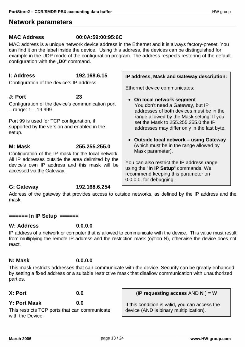
IP address, Mask and Gateway description: Ethernet device communicates:
• On local network segment You don’t need a Gateway, but IP addresses of both devices must be in the range allowed by the Mask setting. If you set the Mask to 255.255.255.0 the IP addresses may differ only in the last byte.
• Outside local network – using Gateway
(which must be in the range allowed by Mask parameter).
You can also restrict the IP address range using the “In IP Setup“ commands. We recommend keeping this parameter on 0.0.0.0. for debugging.
PortStore2 – CDR/SMDR PBX accounting data buffer HW group
March 2006 page 14 / 24 www.HW-group.com
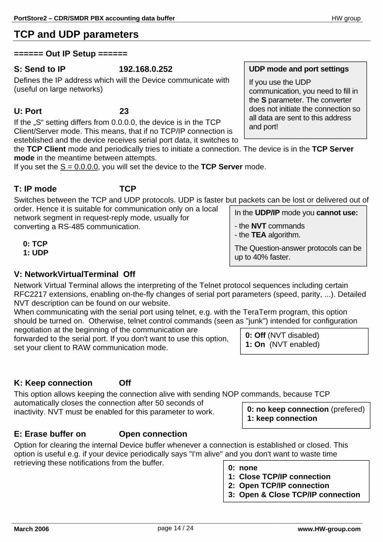
UDP mode and port settings
If you use the UDP communication, you need to fill in the S parameter. The converter does not initiate the connection so all data are sent to this address and port!
In the UDP/IP mode you cannot use:
- the NVT commands - the TEA algorithm.
The Question-answer protocols can be up to 40% faster.
TCP and UDP parameters
====== Out IP Setup ======
S: Send to IP 192.168.0.252 Defines the IP address which will the Device communicate with (useful on large networks)
U: Port 23 If the „S“ setting differs from 0.0.0.0, the device is in the TCP Client/Server mode. This means, that if no TCP/IP connection is esteblished and the device receives serial port data, it switches to the TCP Client mode and periodically tries to initiate a connection. The device is in the TCP Server mode in the meantime between attempts. If you set the S = 0.0.0.0, you will set the device to the TCP Server mode.
T: IP mode TCP Switches between the TCP and UDP protocols. UDP is faster but packets can be lost or delivered out of order. Hence it is suitable for communication only on a local network segment in request-reply mode, usually for converting a RS-485 communication.
0: TCP 1: UDP
V: NetworkVirtualTerminal Off Network Virtual Terminal allows the interpreting of the Telnet protocol sequences including certain RFC2217 extensions, enabling on-the-fly changes of serial port parameters (speed, parity, ...). Detailed NVT description can be found on our website. When communicating with the serial port using telnet, e.g. with the TeraTerm program, this option should be turned on. Otherwise, telnet control commands (seen as "junk") intended for configuration negotiation at the beginning of the communication are forwarded to the serial port. If you don't want to use this option, set your client to RAW communication mode.
K: Keep connection Off This option allows keeping the connection alive with sending NOP commands, because TCP automatically closes the connection after 50 seconds of inactivity. NVT must be enabled for this parameter to work.
E: Erase buffer on Open connection Option for clearing the internal Device buffer whenever a connection is established or closed. This option is useful e.g. if your device periodically says "I'm alive" and you don't want to waste time retrieving these notifications from the buffer.
0: no keep connection (prefered)1: keep connection
0: none 1: Close TCP/IP connection 2: Open TCP/IP connection 3: Open & Close TCP/IP connection
0: Off (NVT disabled) 1: On (NVT enabled)
PortStore2 – CDR/SMDR PBX accounting data buffer HW group
March 2006 page 15 / 24 www.HW-group.com
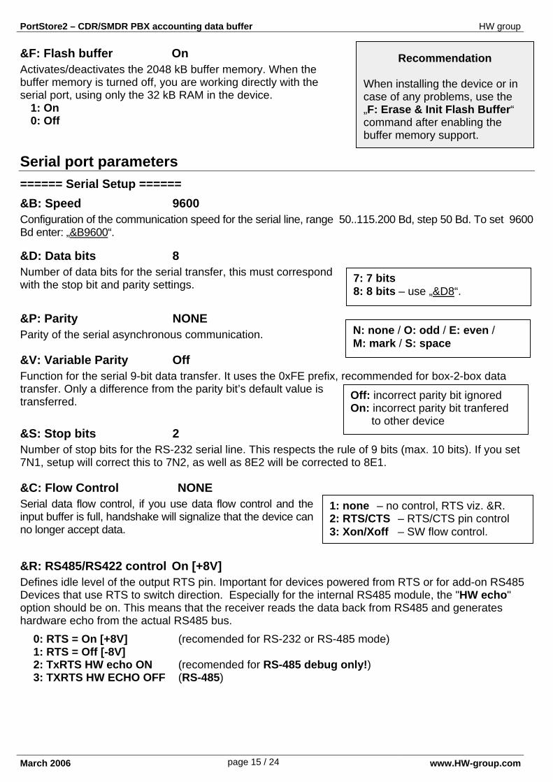
Recommendation When installing the device or in case of any problems, use the „F: Erase & Init Flash Buffer“ command after enabling the buffer memory support.
&F: Flash buffer On Activates/deactivates the 2048 kB buffer memory. When the buffer memory is turned off, you are working directly with the serial port, using only the 32 kB RAM in the device.
1: On 0: Off
Serial port parameters ====== Serial Setup ======
&B: Speed 9600 Configuration of the communication speed for the serial line, range 50..115.200 Bd, step 50 Bd. To set 9600 Bd enter: „&B9600“.
&D: Data bits 8 Number of data bits for the serial transfer, this must correspond with the stop bit and parity settings.
&P: Parity NONE Parity of the serial asynchronous communication.
&V: Variable Parity Off Function for the serial 9-bit data transfer. It uses the 0xFE prefix, recommended for box-2-box data transfer. Only a difference from the parity bit’s default value is transferred.
&S: Stop bits 2 Number of stop bits for the RS-232 serial line. This respects the rule of 9 bits (max. 10 bits). If you set 7N1, setup will correct this to 7N2, as well as 8E2 will be corrected to 8E1.
&C: Flow Control NONE Serial data flow control, if you use data flow control and the input buffer is full, handshake will signalize that the device can no longer accept data. &R: RS485/RS422 control On [+8V] Defines idle level of the output RTS pin. Important for devices powered from RTS or for add-on RS485 Devices that use RTS to switch direction. Especially for the internal RS485 module, the "HW echo" option should be on. This means that the receiver reads the data back from RS485 and generates hardware echo from the actual RS485 bus.
0: RTS = On [+8V] (recomended for RS-232 or RS-485 mode) 1: RTS = Off [-8V] 2: TxRTS HW echo ON (recomended for RS-485 debug only!) 3: TXRTS HW ECHO OFF (RS-485)
1: none – no control, RTS viz. &R. 2: RTS/CTS – RTS/CTS pin control 3: Xon/Xoff – SW flow control.
7: 7 bits 8: 8 bits – use „&D8“.
N: none / O: odd / E: even / M: mark / S: space
Off: incorrect parity bit ignored On: incorrect parity bit tranfered to other device
PortStore2 – CDR/SMDR PBX accounting data buffer HW group
March 2006 page 16 / 24 www.HW-group.com
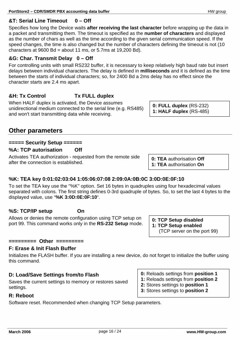
0: Reloads settings from position 1 1: Reloads settings from position 2 2: Stores settings to position 1 3: Stores settings to position 2
&T: Serial Line Timeout 0 – Off Specifies how long the Device waits after receiving the last character before wrapping up the data in a packet and transmitting them. The timeout is specified as the number of characters and displayed as the number of chars as well as the time according to the given serial communication speed. If the speed changes, the time is also changed but the number of characters defining the timeout is not (10 characters at 9600 Bd = about 11 ms, or 5.7ms at 19,200 Bd).
&G: Char. Transmit Delay 0 – Off For controlling units with small RS232 buffer, it is necessary to keep relatively high baud rate but insert delays between individual characters. The delay is defined in milliseconds and it is defined as the time between the starts of individual characters; so, for 2400 Bd a 2ms delay has no effect since the character starts are 2.4 ms apart.
&H: Tx Control Tx FULL duplex When HALF duplex is activated, the Device assumes unidirectional medium connected to the serial line (e.g. RS485) and won't start transmitting data while receiving. Other parameters
===== Security Setup ====== %A: TCP autorisation Off Activates TEA authorization - requested from the remote side after the connection is established.
%K: TEA key 0:01:02:03:04 1:05:06:07:08 2:09:0A:0B:0C 3:0D:0E:0F:10 To set the TEA key use the "%K" option. Set 16 bytes in quadruples using four hexadecimal values separated with colons. The first string defines 0-3rd quadruple of bytes. So, to set the last 4 bytes to the displayed value, use “%K 3:0D:0E:0F:10“.
%S: TCP/IP setup On Allows or denies the remote configuration using TCP setup on port 99. This command works only in the RS-232 Setup mode.
========= Other ========= F: Erase & Init Flash Buffer Initializes the FLASH buffer. If you are installing a new device, do not forget to initialize the buffer using this command.
D: Load/Save Settings from/to Flash Saves the current settings to memory or restores saved settings.
R: Reboot Software reset. Recommended when changing TCP Setup parameters.
0: FULL duplex (RS-232) 1: HALF duplex (RS-485)
0: TEA authorisation Off 1: TEA authorisation On
0: TCP Setup disabled 1: TCP Setup enabled (TCP server on the port 99)

PortStore2 – CDR/SMDR PBX accounting data buffer HW group
March 2006 page 17 / 24 www.HW-group.com
Setup example If you need to send all data from the serial line to the opposite side, use: *L: Trigger Length 0 *P: Post Trigger Length 0 *S: Start Trigger Pattern 0.0.0.0 *M: Start Trigger Mask 0.0.0.0 *X: Stop Trigger Pattern 255.0.0.0 *Y: Stop Trigger Mask 255.0.0.0 *E: Max. Start-Stop Length 200
(The 4 input bytes of data AND *M ) = *S
(The 4 input bytes of data AND *Y ) = *X
UDP/IP mode settings If you select „T: IP mode UDP“, the device will communicate with the remote side using unacknowledged UDP packets. Also, the following menu appears in the setup.
==== Triggering Setup ===== *L: Trigger Length 1
Number of bytes of the starting and ending packet trigger condition. Allowed values are from 0 to 4. If the lengths of your start and stop triggers differ, use the trigger mask and don't forget to include the masked characters in the lengths - even though they contain actual frame data.
*P: Post Trigger Length 0 In some protocols, checksum or other info follows the stop trigger. This value defines the number of characters after the stop trigger that should be included in the packet. If the start and stop triggers are equal, this value specifies packet length without the 0..4 bytes of start trigger.
*S: Start Trigger Pattern 58.0.0.0 Start trigger for packet transmission. Four bytes are set but only the number of bytes specified in "L: Trigger Length" is considered
*X: Stop Trigger Pattern 10.0.0.0 Sets the stop trigger for sending data to the Ethernet.
*M: Start Trigger Mask 255.0.0.0 Mask of the start trigger. Masking works similarly to the Ethernet netmasks using a bitwise AND. Value of 255 means that the tested character must be equal to the character specified in "*S: Start Trigger Pattern". For example, to start the transfer with any control ASCII character (0..31d) use 0.0.0.0 for the trigger pattern, 224.0.0.0 for the mask and 1 for the length. If you set both the character and the mask to 0 the trigger activates for any character.
*Y: Stop Trigger Mask 255.0.0.0 Mask of the stop packet trigger for serial line data. For example, the settings displayed here are intended for transferring data in the IntelHEX format over RS485. The start trigger is a colon and the transfer is terminated after receiving the control character <LF> (0Ah = 10d).
*E: Max. Start-Stop Length 999 Maximum number of characters sent after the START trigger, if the STOP trigger is not found sooner. After transmission, another START trigger is expected. Essentially, this is a "timeout" specified as the number of characters
PortStore2 – CDR/SMDR PBX accounting data buffer HW group
March 2006 page 18 / 24 www.HW-group.com
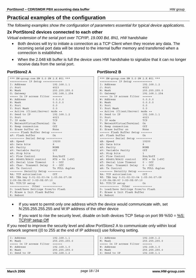
Practical examples of the configuration The following examples show the configuration of parameters essential for typical device applications.
2x PortStore2 devices connected to each other Virtual extension of the serial port over TCP/IP, 19.000 Bd, 8N1, HW handshake
• Both devices will try to initiate a connection as a TCP Client when they receive any data. The incoming serial port data will be stored to the internal buffer memory and transferred when a connection is established.
• When the 2.048 kB buffer is full the device uses HW handshake to signalize that it can no longer receive data from the serial port.
PortStore2 A *** HW-group.com HW 5.0 SW 2.K #01 *** =========== IP Setup ============ I: Address 192.168.1.1 J: Port 4023 M: Mask 255.255.255.0 G: Gateway 192.168.1.254 ===== In IP access filter ====== W: Address 0.0.0.0 N: Mask 0.0.0.0 X: Port 0.0 Y: Port Mask 0.0 == Active (Client/Server) mode == S: Send to IP 192.168.1.2 U: Port 4023 T: IP mode TCP V: NetworkVirtualTerminal On K: Keep connection Off E: Erase buffer on None ====== Flash Buffer Setup ======= &F: Flash buffer On ========= Serial Setup ========== &B: Speed 19200 &D: Data bits 8 &P: Parity NONE &V: Variable Parity Off &S: Stop bits 1 &C: Flow Control Xon/Xoff &R: RS485/RS422 control RTS = On [+8V] &T: Serial Line Timeout 0 - Off &G: Char. Transmit Delay 0 - Off &H: Tx Control Tx FULL duplex ======== Security Setup ========= %A: TCP autorisation Off %K: TEA key 0:01:02:03:04 1:05:06:07:08 2:09:0A:0B:0C 3:0D:0E:0F:10 %S: TCP/IP setup On ============ Other ============ D: Load/Save Settings from/to Flash F: Erase & Init Flash Buffer R: Reboot
PortStore2 B *** HW-group.com HW 5.0 SW 2.K #01 *** =========== IP Setup ============ I: Address 192.168.1.2 J: Port 4023 M: Mask 255.255.255.0 G: Gateway 192.168.1.254 ===== In IP access filter ====== W: Address 0.0.0.0 N: Mask 0.0.0.0 X: Port 0.0 Y: Port Mask 0.0 == Active (Client/Server) mode == S: Send to IP 192.168.1.1 U: Port 4023 T: IP mode TCP V: NetworkVirtualTerminal On K: Keep connection Off E: Erase buffer on None ====== Flash Buffer Setup ======= &F: Flash buffer On ========= Serial Setup ========== &B: Speed 19200 &D: Data bits 8 &P: Parity NONE &V: Variable Parity Off &S: Stop bits 1 &C: Flow Control Xon/Xoff &R: RS485/RS422 control RTS = On [+8V] &T: Serial Line Timeout 0 - Off &G: Char. Transmit Delay 0 - Off &H: Tx Control Tx FULL duplex ======== Security Setup ========= %A: TCP autorisation Off %K: TEA key 0:01:02:03:04 1:05:06:07:08 2:09:0A:0B:0C 3:0D:0E:0F:10 %S: TCP/IP setup On ============ Other ============ D: Load/Save Settings from/to Flash F: Erase & Init Flash Buffer R: Reboot
• If you want to permit only one address which the device would communicate with, set N:255.255.255.255 and W:IP address of the other device
• If you want to rise the security level, disable on both devices TCP Setup on port 99 %S0 = %S: TCP/IP setup Off
If you need to improve the security level and allow PortStore2 A to communicate only within local network segment ((0 to 255 at the end of IP address)) use following setting.
I: Address 192.168.1.1 M: Mask 255.255.255.0 ===== In IP access filter ====== W: Address 192.168.1.0 N: Mask 255.255.255.0 S: Send to IP 192.168.1.2
I: Address 192.168.1.2 M: Mask 255.255.255.0 ===== In IP access filter ====== W: Address 192.168.1.0 N: Mask 255.255.255.0 S: Send to IP 192.168.1.1
PortStore2 – CDR/SMDR PBX accounting data buffer HW group
March 2006 page 19 / 24 www.HW-group.com
Configuration of the device - FAQ • Ethernet has stopped working but the LINK LED is lit.
Check if the device isn’t in the “RS-232 Setup“ mode, which is turned on by setting DIP1 = ON? If the device is in this mode the Ethernet part does not respond. Set the jumper to DIP1 = OFF and reboot the device by disconnecting of the power supply for at least 3 seconds.
• The RS-485 communication does not work Check if you have connected the Termination resistors (120 – 470 ohms) to the line or connector. If you are using a RS485 conversion, set the configuration to &R3 and do not forget to turn the HALF DUPLEX on with setting &H1.
• I need to power another RS-232 device If you do not need to regulate the data flow (HW handshake) and at the same time need a supply voltage for the device on serial port (up to 5-10 mA) power your application from the RTS output (pin 7 on RS-232 connector). Voltage of circa +8V to +12V can be activated on this pin by &R0 option in the reset mode (&R: RS485/RS422 control).
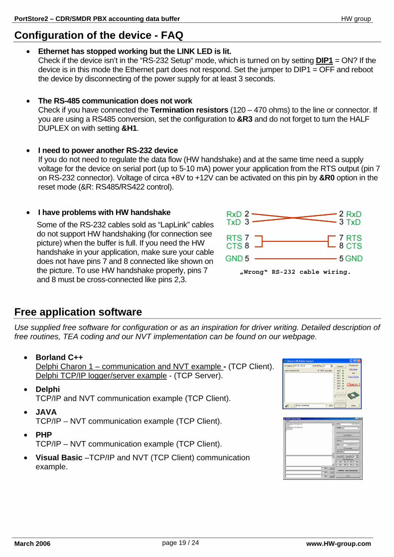
• I have problems with HW handshake
Some of the RS-232 cables sold as “LapLink” cables do not support HW handshaking (for connection see picture) when the buffer is full. If you need the HW handshake in your application, make sure your cable does not have pins 7 and 8 connected like shown on the picture. To use HW handshake properly, pins 7 and 8 must be cross-connected like pins 2,3.
Free application software Use supplied free software for configuration or as an inspiration for driver writing. Detailed description of free routines, TEA coding and our NVT implementation can be found on our webpage.
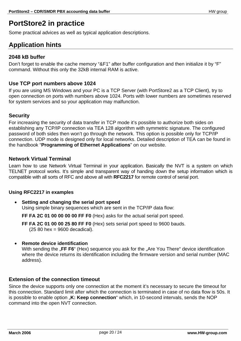
• Borland C++ Delphi Charon 1 – communication and NVT example - (TCP Client). Delphi TCP/IP logger/server example - (TCP Server).
• Delphi TCP/IP and NVT communication example (TCP Client).
• JAVA TCP/IP – NVT communication example (TCP Client).
• PHP TCP/IP – NVT communication example (TCP Client).
• Visual Basic –TCP/IP and NVT (TCP Client) communication example.
„Wrong“ RS-232 cable wiring.
PortStore2 – CDR/SMDR PBX accounting data buffer HW group
March 2006 page 20 / 24 www.HW-group.com
PortStore2 in practice Some practical advices as well as typical application descriptions. Application hints
2048 kB buffer Don’t forget to enable the cache memory “&F1” after buffer configuration and then initialize it by “F” command. Without this only the 32kB internal RAM is active.
Use TCP port numbers above 1024 If you are using MS Windows and your PC is a TCP Server (with PortStore2 as a TCP Client), try to open connection on ports with numbers above 1024. Ports with lower numbers are sometimes reserved for system services and so your application may malfunction.
Security For increasing the security of data transfer in TCP mode it’s possible to authorize both sides on establishing any TCP/IP connection via TEA 128 algorithm with symmetric signature. The configured password of both sides then won’t go through the network. This option is possible only for TCP/IP connection. UDP mode is designed only for local networks. Detailed description of TEA can be found in the handbook “Programming of Ethernet Applications” on our website.
Network Virtual Terminal Learn how to use Network Virtual Terminal in your application. Basically the NVT is a system on which TELNET protocol works. It’s simple and transparent way of handing down the setup information which is compatible with all sorts of RFC and above all with RFC2217 for remote control of serial port. Using RFC2217 in examples
• Setting and changing the serial port speed Using simple binary sequences which are sent in the TCP/IP data flow: FF FA 2C 01 00 00 00 00 FF F0 (Hex) asks for the actual serial port speed. FF FA 2C 01 00 00 25 80 FF F0 (Hex) sets serial port speed to 9600 bauds.
(25 80 hex = 9600 decadical).
• Remote device identification With sending the „FF F6“ (Hex) sequence you ask for the „Are You There“ device identification where the device returns its identification including the firmware version and serial number (MAC address).
Extension of the connection timeout Since the device supports only one connection at the moment it’s necessary to secure the timeout for this connection. Standard limit after which the connection is terminated in case of no data flow is 50s. It is possible to enable option „K: Keep connection“ which, in 10-second intervals, sends the NOP command into the open NVT connection.
PortStore2 – CDR/SMDR PBX accounting data buffer HW group
March 2006 page 21 / 24 www.HW-group.com
Typical applications The typical application of the PortStore2 device is a remote access to a RS-232/RS-485 technology. In case there is no TCP connection available the device stores the incoming serial port data to the internal Flash 2.048kB buffer memory. If the Portstore2 device is in the TCP Client mode, it tries to initialize the connection and send the data stored in the internal buffer. The data is stored in a "RAW" format in the delivered order. The device acts as standard terminal server with a remote serial port access.
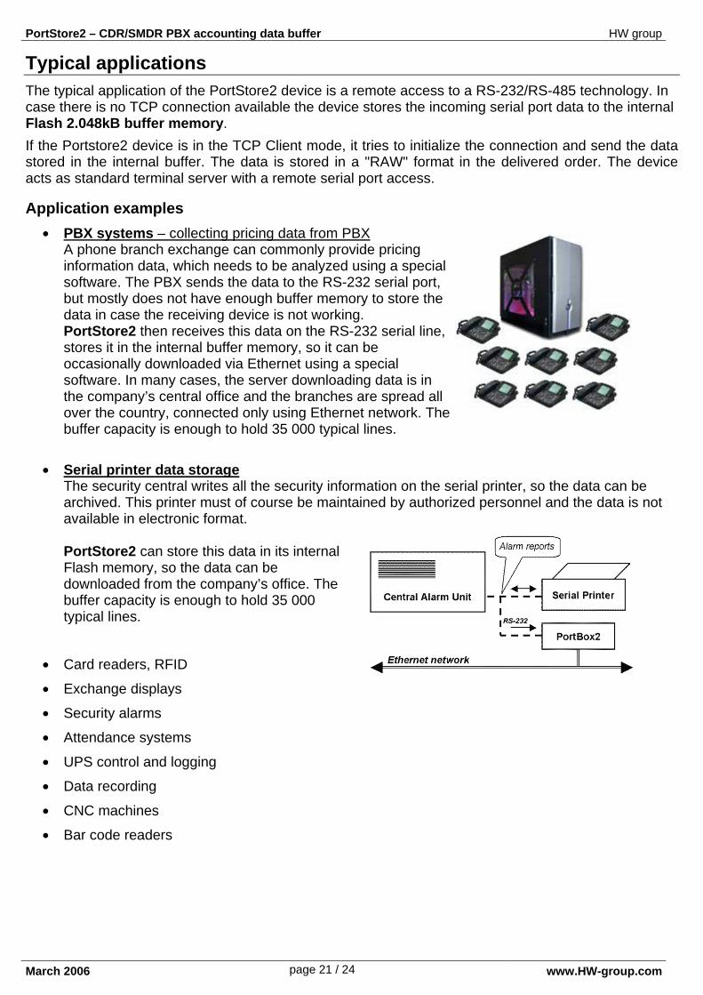
Application examples • PBX systems – collecting pricing data from PBX
A phone branch exchange can commonly provide pricing information data, which needs to be analyzed using a special software. The PBX sends the data to the RS-232 serial port, but mostly does not have enough buffer memory to store the data in case the receiving device is not working. PortStore2 then receives this data on the RS-232 serial line, stores it in the internal buffer memory, so it can be occasionally downloaded via Ethernet using a special software. In many cases, the server downloading data is in the company’s central office and the branches are spread all over the country, connected only using Ethernet network. The buffer capacity is enough to hold 35 000 typical lines.
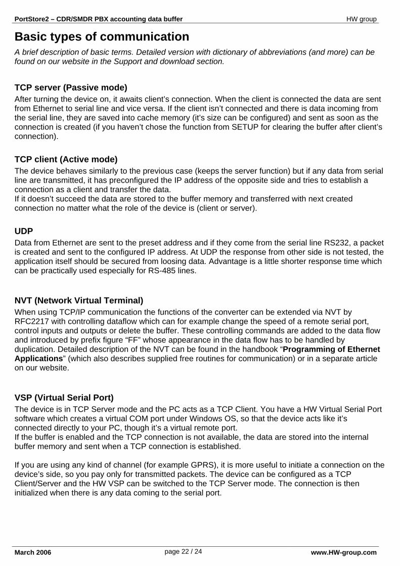
• Serial printer data storage The security central writes all the security information on the serial printer, so the data can be archived. This printer must of course be maintained by authorized personnel and the data is not available in electronic format. PortStore2 can store this data in its internal Flash memory, so the data can be downloaded from the company’s office. The buffer capacity is enough to hold 35 000 typical lines.
• Card readers, RFID
• Exchange displays
• Security alarms
• Attendance systems
• UPS control and logging
• Data recording
• CNC machines
• Bar code readers
PortStore2 – CDR/SMDR PBX accounting data buffer HW group
March 2006 page 22 / 24 www.HW-group.com
Basic types of communication A brief description of basic terms. Detailed version with dictionary of abbreviations (and more) can be found on our website in the Support and download section.
TCP server (Passive mode) After turning the device on, it awaits client’s connection. When the client is connected the data are sent from Ethernet to serial line and vice versa. If the client isn’t connected and there is data incoming from the serial line, they are saved into cache memory (it’s size can be configured) and sent as soon as the connection is created (if you haven’t chose the function from SETUP for clearing the buffer after client’s connection).
TCP client (Active mode) The device behaves similarly to the previous case (keeps the server function) but if any data from serial line are transmitted, it has preconfigured the IP address of the opposite side and tries to establish a connection as a client and transfer the data. If it doesn’t succeed the data are stored to the buffer memory and transferred with next created connection no matter what the role of the device is (client or server).
UDP Data from Ethernet are sent to the preset address and if they come from the serial line RS232, a packet is created and sent to the configured IP address. At UDP the response from other side is not tested, the application itself should be secured from loosing data. Advantage is a little shorter response time which can be practically used especially for RS-485 lines.
NVT (Network Virtual Terminal) When using TCP/IP communication the functions of the converter can be extended via NVT by RFC2217 with controlling dataflow which can for example change the speed of a remote serial port, control inputs and outputs or delete the buffer. These controlling commands are added to the data flow and introduced by prefix figure “FF” whose appearance in the data flow has to be handled by duplication. Detailed description of the NVT can be found in the handbook “Programming of Ethernet Applications” (which also describes supplied free routines for communication) or in a separate article on our website.
VSP (Virtual Serial Port) The device is in TCP Server mode and the PC acts as a TCP Client. You have a HW Virtual Serial Port software which creates a virtual COM port under Windows OS, so that the device acts like it’s connected directly to your PC, though it’s a virtual remote port. If the buffer is enabled and the TCP connection is not available, the data are stored into the internal buffer memory and sent when a TCP connection is established. If you are using any kind of channel (for example GPRS), it is more useful to initiate a connection on the device’s side, so you pay only for transmitted packets. The device can be configured as a TCP Client/Server and the HW VSP can be switched to the TCP Server mode. The connection is then initialized when there is any data coming to the serial port.
PortStore2 – CDR/SMDR PBX accounting data buffer HW group
March 2006 page 23 / 24 www.HW-group.com
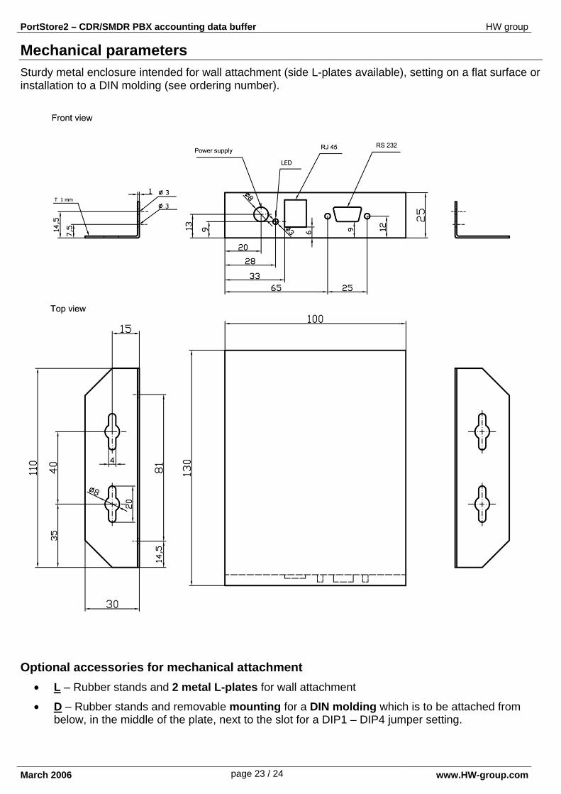
Mechanical parameters Sturdy metal enclosure intended for wall attachment (side L-plates available), setting on a flat surface or installation to a DIN molding (see ordering number).
Optional accessories for mechanical attachment • L – Rubber stands and 2 metal L-plates for wall attachment
• D – Rubber stands and removable mounting for a DIN molding which is to be attached from below, in the middle of the plate, next to the slot for a DIP1 – DIP4 jumper setting.
PortStore2 – CDR/SMDR PBX accounting data buffer HW group
March 2006 page 24 / 24 www.HW-group.com
Ordering number OID (Ordering ID) Products
600 037 PortStore2 PortStore unit, without any accessory
600 038
PortStore2 set Recommended starting set contains: - PortStore2 [600037] - EU [600080] or USA [600081] or UK [600082] Power adaptor - DB9 LapLink cable 2m [600063] - Manual, CD
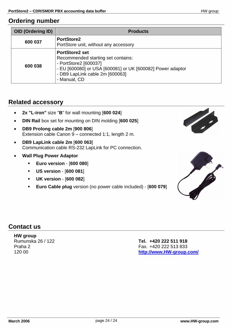
Related accessory
• 2x "L-iron" size "B" for wall mounting [600 024]
• DIN Rail box set for mounting on DIN molding [600 025]
• DB9 Prolong cable 2m [900 806] Extension cable Canon 9 – connected 1:1, length 2 m.
• DB9 LapLink cable 2m [600 063] Communication cable RS-232 LapLink for PC connection.
• Wall Plug Power Adaptor Euro version - [600 080] US version - [600 081] UK version - [600 082] Euro Cable plug version (no power cable included) - [600 079]
Contact us
HW group Rumunska 26 / 122 Tel. +420 222 511 918 Praha 2 Fax. +420 222 513 833 120 00 http://www.HW-group.com/