
RR-PILING TO RUSSIAN NORMS AND NOISE BARRIER …
44
Saimaa University of Applied Sciences Technology, Lappeenranta Double Degree Programme in Civil and Construction Engineering Shkolnikov Mikhail RR-PILING TO RUSSIAN NORMS AND NOISE BARRIER FOUNDATIONS Bachelor’s Thesis 2010
Transcript of RR-PILING TO RUSSIAN NORMS AND NOISE BARRIER …

Saimaa University of Applied Sciences Technology, Lappeenranta Double Degree Programme in Civil and Construction Engineering Shkolnikov Mikhail
RR-PILING TO RUSSIAN NORMS AND NOISE BARRIER FOUNDATIONS Bachelor’s Thesis 2010

1
CONTENTS
ABSTRACT ......................................................................................................... 3
TERMINOLOGY, SYMBOLS AND ABBREVIATIONS ........................................ 4
1 INTRODUCTION ............................................................................................. 5
1.1 Basis for the research ......................................................................................... 5
1.2 Objectives ............................................................................................................. 5
1.3 Implementation of the research ......................................................................... 5
2 NOISE BARRIER BASED ON A SINGLE STEEL PIPE PILE FOUNDATION . 6
2.1 Structure of the Ruukki noise barrier system .................................................. 6
2.2 RR-piles ................................................................................................................. 8
2.3 Foundations ........................................................................................................ 10
2.4 Columns and plinth elements .......................................................................... 12
2.5 Noise barrier cassettes ..................................................................................... 14
3 DESIGN OF NOISE BARRIER FOUNDATIONS AND COLUMNS ACCORDING TO EUROCODES AND RUSSIAN NORMS .............................. 14
3.1 Basic principles of design ................................................................................. 15
3.2 Loads ................................................................................................................... 16
3.2.1 Wind load ......................................................................................................... 16
3.2.2 Ploughing load ................................................................................................ 18
3.2.3 Vertical load ..................................................................................................... 19
3.3 Design requirements ......................................................................................... 19
3.4 Geotechnical design .......................................................................................... 20
3.4.1 Design principle of horizontally and/or vertically loaded pile according to Eurocodes .................................................................................................................. 21
3.4.2 Design principle of horizontally and/or vertically loaded pile according to Russian norms .......................................................................................................... 25
3.5 Structural design ................................................................................................ 30
3.5.1 Design principle of horizontally and/or vertically loaded column according to Eurocodes ........................................................................................... 30
3.5.2 Design principle of horizontally and/or vertically loaded column according to Russian norms ................................................................................... 32
3.5.3 Structural design of a pile .............................................................................. 32
3.5.4 Structural design of a column ....................................................................... 33
3.5.5 Corrosion ......................................................................................................... 33
3.5.6 Dimensioning of connection plates and base bolts ................................... 35
3.6 Comparison between Eurocodes and Russian norms ................................ 37
4 CASE STUDY ................................................................................................ 39
4.1 Noise barriers in Saint-Petersburg .................................................................. 40
2
4.2 Kouvola Myllykallio project ............................................................................... 40
5 CONCLUSIONS ............................................................................................. 41
6 FIGURES ....................................................................................................... 42
7 TABLES ......................................................................................................... 42
8 REFERENCES .............................................................................................. 43
APPENDIXES:
Appendix 1 Mathcad 14 calculation file
Appendix 2 SCAD calculation file
Appendix 3 SCAD calculation, a Word 97 table of the results
3
ABSTRACT
Shkolnikov Mikhail Lvovich
RR piling to Russian norms and noise barrier foundations, 43 pages, 4
appendixes
Saimaa University of Applied Sciences, Lappeenranta
Degree Programme in Civil and Construction Engineering
Bachelor´s Thesis 2010
Instructors: Mr Veli-Matti Uotinen, Technical Manager, Ruukki
Mr Tero Liutu, Senior Lecturer
Mr Matti Hakulinen, Senior Lecturer
RR-piles are steel piles, which are assembled from parts on the construction
site. A noise barrier cassette is a noise screen made of steel and polyester
wool. The whole construction is assembled from rolled H-section columns and
cassettes, attached to H-section flanges with bolts through drilled holes. The
columns are connected to the top of the RR-piles.
The objective of the study is to make the application of this construction easier
in Russia. Nowadays this construction is very seldom used in Russia, but if it
can be ensured that all design and calculation methods are suitable to SNiP
and GOST norms, this construction can be easier promoted into the Russian
market.
The method was to find all Russian norms needed for calculations and to
calculate pile and column structures according to them. Also for having the
basic view it was useful to interview engineers and managers from Ruukki and
lecturers from Saimaa UAS and SPSUACE.
Keywords: Ruukki; RR-pile; noise barrier NBC-95; Eurocodes; SNiP; GOST

4
TERMINOLOGY, SYMBOLS AND ABBREVIATIONS
1st limit state – in the calculations of structures according to Russian norms this
is the name of a calculation method by bearing capacity (cross sections of
elements are selected according to bearing capacity).
2nd limit state – this is the name of a calculation method by the movements of
structures in Russian norms.
GOST – Russian State Standard. These standards were made for all products
in the USSR, nowadays a lot of them are still used, but sometimes non-
obligatory and/or replaced/supplemented by Enterprises Standards.
SP – Summary of Rules. These are the standards for construction engineering,
each one has an identification number in the system of standards and their own
name.
SPSUACE – Saint-Petersburg State University of Architecture and Civil
Engineering (the home university of the thesis author).
SNiP – Construction Norms and Regulations. These are standards for
construction engineering, each one has an identification number in the system
of standards and their own name.
Soil characteristics from table 3.5:
φ – angle of internal friction
γ – density
c – adhesion
γs – density of solid parts of soil
W – water content
WL – liquid limit
Wp – plastic limit
kf – coefficient of filtration
E – modulus of deformation
IL – index of fluidity
γd – density of dry soil (soil skeleton)
n – porosity
e – voids ratio (coefficient of porosity)
γsb – density of soil with account of water weighing

5
1 INTRODUCTION
In the introduction the main purpose of the study, sources of information and
time schedule of implementation are described.
1.1 Basis for the research
This study was made for Rautaruukki Corporation and the Saimaa University of
Applied Sciences. The supervisor was Veli-Matti Uotinen, technical manager
from the Ruukki Construction, Infrastructure construction.
RR-piles are steel piles, which are assembled from parts: a rock shoe or a
bottom plate in the bottom part, the selection between them depends on the
type of soil; internal or external splices for connections if the pile is assembled
from parts; and a bearing plate on the top of the pile.
A noise barrier cassette is a noise screen made of steel and polyester wool.
The whole construction is assembled from rolled H-section columns and
cassettes, attached to H-section flanges with bolts through drilled holes.
Columns are connected to the top of the RR-piles.
1.2 Objectives
The main aim of this study is to make the application of this construction easier
in Russia. Nowadays delivery of these cassettes to Russia is just beginning, but
if it can be proven that all design and calculation methods are suitable to the
SNiP and GOST norms, this construction can be faster promoted into the
Russian market.
1.3 Implementation of the research
09.02.2010 - start meeting.
15.02.2010 - excursion to the Kouvola Myllykallio noise barrier construction site.
15.02.2010 - 01.03.2010 - discovering all norms, regulations and literature
needed for work.

6
01.03.2010 - approx. 31.03.2010 - writing the first version of the thesis report
and sending this to Veli-Matti Uotinen, Tero Liutu and Matti Hakulinen for
corrections.
31.03.2010 - 30.04.2010 - correcting all mistakes.
31.04.2010 - 06.05.2010 - final check and preparing for presentations.
2 NOISE BARRIER BASED ON A SINGLE STEEL PIPE PILE
FOUNDATION
In this chapter all elements of Ruukki’s noise barrier structure are described in
general without calculations.
2.1 Structure of the Ruukki noise barrier system
Mainly the structure of this system consists of four parts:
RR-piles
Foundations
Columns and plinth elements
Noise barrier cassettes
RR-piles are steel pipe piles. Foundations of the Ruukki noise barrier system
usually consist of single steel pipe piles and connection plates through which
columns are connected. Columns and plinth structures are usually made of
steel S355J2 and have zinc layer thickness 80 – 100 microns (micrometres).
Noise barrier cassettes have dimensions of 2500-5000 x 520 x 95 mm, they
consist of steel lists, connectors and absorbing wool layer.

7
Here is a schematic picture for better understanding of the whole structure:
Figure 2.1 The basic structure of Ruukki’s noise barrier structure (a misprint in
illustration: NBC-95 instead of NBC-10)

8
2.2 RR-piles
RR-piles are impact-driven steel pipe piles used for bearing the whole upper
structure. The arrangement of these piles is shown on figure 2.2:
Figure 2.2 Structure of RR-pile sizes RR75 - RR220
The simplest pile which can be made is just the pipe with a bearing plate. If
needed by a project, the bottom plate or rock shoe can be added for better
footing. Also for making longer piles from standard length elements external or
internal splices can be used.

9
RR-piles have requirements for piling classes. Piling class selection depends on
how demanding the structure is. The requirements for RR-piling construction
site are shown in the table 2.1:
Table 2.1 Requirements for RR-piles according to PPO-2007
Piling class III Piling class II Piling class I B
Easy projects Demanding projects Very demanding projects
Lightweight and basic buildings and constructions, not intended for permanent habitation.
Lightweight and basic residential buildings and constructions.
Bridges, hydraulic structures, industrial structures and other corresponding engineering structures; Structures subject to dynamic or otherwise exceptional loads such as significant horizontal loads, bending or heavy vertical loads, or special requirements.
Sites with easy soil conditions.
Sites with easy soil conditions.
Large or complicated structures and buildings located in areas of organic or fine grained soils; Sites where rock is overlaid only by organic or fine-grained soils; Structures incorporating piles driven through thick fill.
To build foundations on these piles we need to make ground investigations.
These investigations help us to know the stability of soil, groundwater level, etc.
Normally the piling class with noise barrier foundations is II. Also piling class IB
is used when the soil conditions are more complicated and/or the height of the
noise barrier is higher than 3 - 4 m, or the structure is somehow deviating from
normal.
RR-pile materials and details:
Steel grades:
RR-piles sizes RR75 – RR220 are made of S440J2H steel, which has yield
strength 440 MPa. The technical characteristics of piles conform to EN 10219

10
standard except the straightness, which is 1,25/1000 and the length tolerance,
which is ±50 mm.
Sections and accessories:
The diameter of RR-piles vary from 76,1 mm (RR75) to 219,1 mm (RR220). The
wall thickness varies from 6,3 mm to 12,5 mm. The standard stock lengths of
manufactured piles are 6 or 12 metres. Also, when the project specifies length,
other lengths can be manufactured, e.g. 1; 1,2; 1,5; 2; 3; 4 metres.
Splices manufactured by Ruukki are used with RR piles. The splices are
connected to the pile shaft by friction, no welding on site is needed. The tip of
the pile is protected by a bottom plate or a rock shoe. The bottom plate is more
common, and it is usually determined by investigations if a rock shoe is
required.
Rautaruukki also produces larger diameter piles, longitudinally welded RR270 –
RR320 and spirally welded RR400 – RR1200. The most common piles for noise
barrier foundations are RR270 – RR500. Normally for RR270 – RR400 piles
steel S355J2H is used, because there is not any effect of higher strength steels
on pile movements and inclinations.
2.3 Foundations
Foundations of Ruukki’s noise barrier system consist usually of single steel pipe
piles on which the columns are connected through a connection plate. Piles can
be installed by driving, drilling, or vibration.
The dimensioning requirements usually are:
- structures must not be damaged and the failure of soil must not be occured
when design loads are multiplied by 1,5
- movement of the upper end of the pile must be less than 20 mm in cohesive
soils and 30 mm in non-cohesive soils
- horizontal deflections are within required: column deflection caused by wind
load or ploughing load must be < L/150 (L – height of column); overall deflection

11
of the noise barrier caused by pile inclination, movement of upper end of pile
and column deflection must be < L/75 (L – height of noise barrier)
The installation of driven RR-piles can be made by using various equipment as
drop hammers, hydraulic hammers, accelerated hydraulic hammers, pneumatic
and hydraulic rams or vibrators. They can be easily attached to, for example,
track-guided excavators. Side-grip based vibrators have proven to be practical
when the installation takes place on electric railways.
In the design of piles, soil corrosion is factored in by over-dimensioning pile wall
thickness. Also the welding seams between the connection plate and steel piles
are over-dimensioned. According to Eurocode 3, part 5, loss in material
thickness because of corrosion is from 0,6 mm to 3,25 mm in 50 years,
depending on the type of soil. It is important to note that the values for the
corrosion of 5 and 25 years and others are extrapolated in the Eurocode.
In Finland there are two authorities which have a different approach to the
corrosion aspect concerning noise barrier foundations:
1. Former Road Administration (Tiehallinto), from 1 January 2010 Finnish
Transport Agency, Road Deparment:
- design life 50 years
- corrosion values according to EN 1993-5 on the external surface of the pile
- internal surface: corrosion is 0 mm, when the pile is closed from both ends,
and 0.1mm, if the pile is open-ended (but at the head of the pile there is a
welded connection plate) (TIEH 2100062-09).
2. Former Railway Administration (RHK), from 1 January 2010 Finnish
Transport Agency, Rail Department:
- design life for foundations 100 years, other structures 50 years
- corrosion when the pile is closed from both ends or inside is concreted 2mm,
when pile is open-ended overall corrosion is 4mm (i.e. 2mm inside the pile!)
(RHK B11).

12
2.4 Columns and plinth elements
Connection between a column and pile is made in the following way:
The base plate with threaded holes for bolts is welded on the pile top. Welding
takes place under shelter to ensure the quality of the welding. This process is
shown in figure 2.3:
Figure 2.3 Installation of base plate by welding
Mounting bolts with nuts are fitted to the base plate. The foundation bolts are
aligned and levelled in order to guarantee tight enough tolerances for the
column installation. Columns are hoisted on their position and bolts and nuts
are tightened. In special cases the space between the base plate and the
bottom plate of the column can be grouted, for example to ensure a longer life
span.
Steel and covering:
Column and plinth structures are always hot dip galvanized according to
standard EN ISO 1461. The steel grade used in these structures is usually
S355J2 with the silicon content of 0.15…0.25 %. With such a steel the typical
thickness of a zinc layer is at minimum 80…100 μm (micrometres) depending
on thickness and dipping time. Another possibility is to use steel with the low

13
silicon content (P+Si ≤ 0,04 %), which gives a thinner zinc layer but a more
shiny surface.
Figure 2.4 Views of the structure
Long-term durability of zinc layers:
According to corrosion tests in Finland, zinc corrodes as shown on the diagram:
Figure 2.5 Zinc layer corrosion
Here we can see for example, that a 250-micrometer zinc layer will stay for 25
years in the Baltic sea water until completely destroyed.

14
2.5 Noise barrier cassettes
NBC-95 is the latest model of the cassette made by Ruukki, the scheme of the
structure is presented here:
Figure 2.6 Structure of a NBC-95 noise barrier cassette
According to the information given on the right, we can say that maximum span
between columns is 5 meters and the weight of one span structure with the
height of 3 metres is 3m x 5m x 26 kg/m2 = 390 kg. The combination of the zinc
layer and PVDF/PVDF HB will give a high corrosion resistance.
3 DESIGN OF NOISE BARRIER FOUNDATIONS AND COLUMNS
ACCORDING TO EUROCODES AND RUSSIAN NORMS
In this chapter the design of the pile and column structure is described. It should
be taken into consideration that the calculations in Finnish method were taken
from the brochures by Rautaruukki and from Veli-Matti Uotinen`s methodology
of calculation, which are both based on RHK B11 and TIEH 2100062-09,
however the calculations are made for KA-10 noise barrier cassettes, which are

15
not produced now, but replaced by NBC-95 cassettes. Comparing them, we can
see that the vertical load from the new cassette is lower because of the weight:
26 kg/m2 instead of 35 kg/m2. Of course this will not affect stability, so the
calculations in the Finnish way are given with the methodology by Ruukki, but
calculations by Russian norms are made for new NBC-95 cassettes.
3.1 Basic principles of design
The design of these structures in Finland is based on the following documents:
EN 1997-1 Eurocode 7: Geotechnical design, Part 1: General Rules
EN 1993-5 Eurocode 3: Design of steel structures – Part 5: Piling
EN 1991-1-1 Eurocode 1: Actions on structures – Part 1-1: General actions –
Densities, self-weight and imposed loads
EN 1991-1-4 Eurocode 1: Actions on structures – Part 1-4: General actions –
Wind actions
EN 10219-2:1997 Cold formed welded structural sections of non-alloy and fine
grain steels. Tolerances, dimensions and sectional properties
RHK B11, Rautateiden meluesteet (Noise barriers of railways)
TIEH 2100062-09 Tien meluesteiden suunnittelu, luonnos 9.122009 (Designing
of road noise barriers, draft for trial use 9.12.2009)
In Russia the following documents for designing noise barrier structures are
used:
SNiP 2.01.07-85 (2003) Loads and actions (Нагрузки и воздействия)
SNiP 23-03-2003 Sound protection (Защита от шума)
SNiP 2.02.03-85 (1995, corrected 2003) Pile foundations (Свайные
фундаменты)
SNiP 2.02.01-83 (2000) Foundations of structures (Основания зданий и
сооружений)
SP 50-102-2003 Design and construction of pile foundations (Проектирование
и устройство свайных фундаментов)
SNiP 2.03.11-85 Protection of structures corrosion (Защита строительных
конструкций от коррозии)

16
Of course, if it is needed, we can also use clear and more detailed information
guidelines where the process of design and calculations is written more
consistently, not like a list of requirements in SNiP. The book by Dalmatov B.I.
is one of this guides.
Shortly, the basic principle of design is the order of actions:
external load calculation;
transferring from external to internal loads;
selecting the type of main structure parts from the range of products,
according to the internal loads factor;
selecting joint details (bolts, welding, etc.) according to internal loads in
the joint.
3.2 Loads
Loads are taken into account in different ways in Eurocodes and in SNiPs.
Further in the text the methodology of taking different loads into account will be
realised.
3.2.1 Wind load
Finnish method:
If specific calculations according to EN 1991-1-4 General actions: Wind load, is
not made, wind load of 1.0 kN/m2 is used in calculations. For noise barriers on
bridges the wind load is 1,6 kN/m2.
Russian method:
According to SNiP ―Loads and actions‖, normative average wind load wm on this
structure on height z is calculated by formula:
wm = γf ·w0 · k ·c (3.1)
where:
γf – safety coefficient for the wind load (this type of coefficients to converse from
normative loads to calculation loads are used), for wind this value is 1,4.

17
w0 – normative value of the wind load (taken from table of SNiP according to the
wind zone of Russia)
Table 3.1 Wind zones of USSR according to SNiP Loads and actions
Wind zones of USSR (taken from the
map 3 of obligatory application 5)
Ia I II III IV V VI VII
w0, kPa 0,17 0,23 0,30 0,38 0,48 0,60 0,73 0,85
k – coefficient, taking into account the change of wind pressure with height
Table 3.2 Coefficient k selection by SNiP Loads and actions
Height z, m Coefficient k for types of locality (situation)*
А В С
5 0,75 0,5 0,4
10 1,0 0,65 0,4
20 1,25 0,85 0,55
40 1,5 1,1 0,8
60 1,7 1,3 1,0
80 1,85 1,45 1,15
100 2,0 1,6 1,25
150 2,25 1,9 1,55
200 2,45 2,1 1,8
250 2,65 2,3 2,0
300 2,75 2,5 2,2
350 2,75 2,75 2,35
480 2,75 2,75 2,75
*А — open coastlines of sea, lakes and water storage ponds; deserts, steppes
(prairies), forest-steppes, tundra;
В — city territories, forests and other places, uniformly covered with barriers,
height more than 10 m;
С — city districts with buildings, height more than 25 m.
c – aerodynamic coefficient, which depends on the scheme of the structure and
the surface (windward or lee (downwind)). For our structure, according to

18
obliging attachment 4 of SNiP Loads and actions, these values are +0,8 for the
windward side and -0,6 for lee side.
3.2.2 Ploughing load
Finnish method: a dynamic load from snow clearance according to EN 1794-1:2003
(annex E) depends on snow ploughing beside the noise barrier and/or what is the
distance from the clearance area to the noise barrier. These loads can be understood
from the following schemes:
Figure 3.1 The effect of height on the dynamic load from snow clearance
Figure 3.2 The magnitude of the dynamic load from snow clearance

19
For example, the dynamic load from a 50 km/h ploughing speed with distance 2 m from
the edge of the ploughed surface causes that the load will be 10 kN for 2x2 m area (or
2,5 kN/m2).
Russian method: not reviewed in SNiP.
3.2.3 Vertical load
Finnish method: a vertical load is the summary load of the self-weight of the column,
plinth elements and noise barrier cassettes.
Russian method: the normative value of the load is known from the factory certificates
for structures, from standards, graphics or from known volumes and densities. For the
converse from the normative to calculation load we need to use coefficient γf = 1,05 for
steel structures (taken from table 1 of SNiP Loads and actions). If soil load has to be
taken into account, coefficient γf = 1,1 for natural soils and γf = 1,15 for fill is used.
3.3 Design requirements
Table 3.3 Design requirements for columns and piles
Parameter Finnish norms Russian norms
Deflection of
column
Road noise barriers (TIEH
2100062-09 standard):
e<h/100 when h<3m
e=30mm, when h=3.0…4.5m
e<h/150, when h>4.5m
where
e – deflection,
h – height
Railroad noise barriers (RHK
B11):
e1<L/150
e2<(2,2·Kp·γ·d)/Nh
e3<L1/75
e3<50 mm
According to SNiP ―Loads and
actions‖, for one-level
constructions with level height ≤ 6
m, deflection must be <hs/150,
where hs is the height from the top
of a foundation to the top of a
column. Foundation inclination is
taken into account.
20
see figure 3.3
Overall deflection
of column
Same as deflection values < hs/150, as in upper cell
(inclination is taken into account).
Bearing capacity
of pile
Must be sufficient against
vertical loads
The same as in the Finnish way,
but the calculation of bearing
capacity is different.
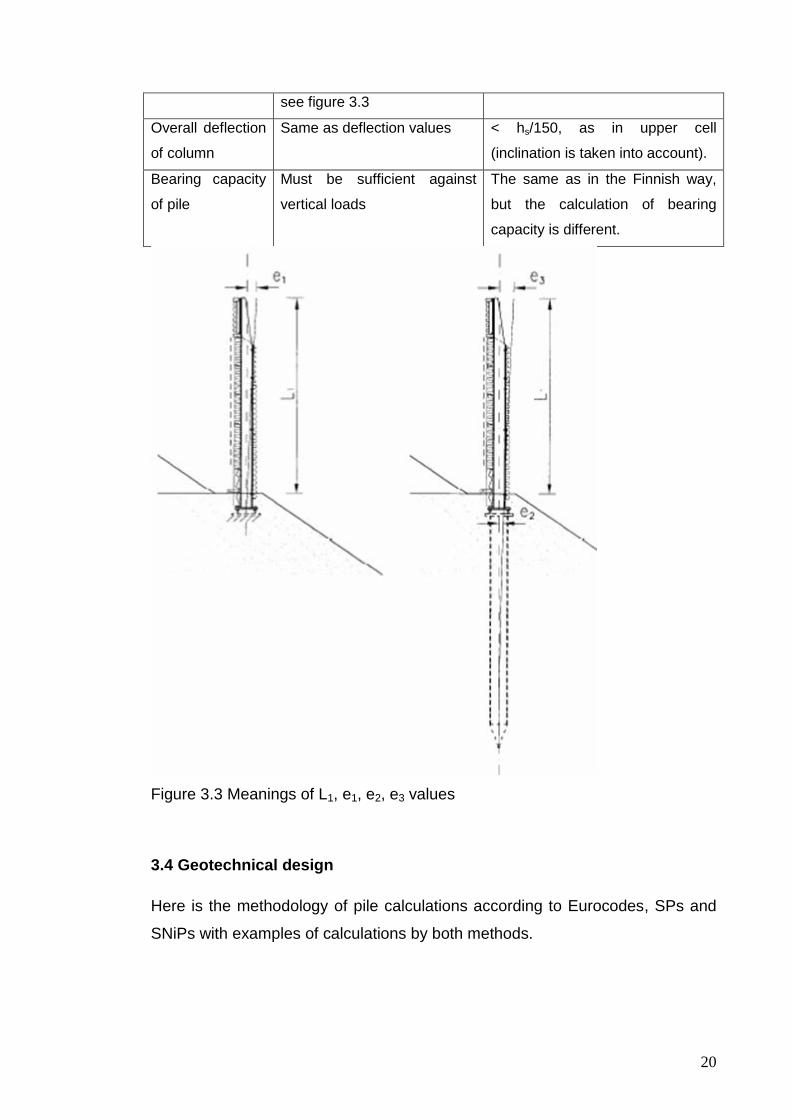
Figure 3.3 Meanings of L1, e1, e2, e3 values
3.4 Geotechnical design
Here is the methodology of pile calculations according to Eurocodes, SPs and
SNiPs with examples of calculations by both methods.

21
3.4.1 Design principle of horizontally and/or vertically loaded pile according to Eurocodes
First all basic data needed for calculations is collected:
1) Height of the noise barrier
2) Slope angle (if the barrier is situated in a slope)
3) Horizontal load:
- wind load, according to EN 1994-1-4, if specific calculations are not
made, 1 kN/m2 is used in calculations
- dynamic load from snow clearance according to EN 1794-1:2003 (annex
E) depend on snow ploughing beside the noise barrier and/or what is the
distance from the clearance area to the noise barrier
4) Vertical load is the summary load of:
- noise barrier cassette and plinth, kg/m2
- column, kg/m
- base plate
- connection plate
- base bolts, screws, accessories etc.
5) Soil conditions
- unit weight [kN/m3],
- friction angle [°]
- undrained shear strength [kN/m2],
- deformation parameters (e.g. modulus ―m‖ and modulus exponent ‖β‖)
The ground water level is discovered and measured by soil investigations: if soil
conditions are homogenous along the noise barrier, approximately one soil
sounding / geotechnical drilling / soil sampling is needed for every 30…60
meters. When soil conditions are non-homogenous along the noise barrier, a
ground survey should be made up to 5 - 10 meter spacing. The survey point
density greatly depends on expected soil conditions.
Pile calculations:
Bearing capacity of a pile:
Vertical loads are calculated as dead loads of noise barrier materials. The
geotechnical bearing capacity of the pile is calculated according to soil

22
parameters and pile dimensions. Noise barrier steel piles are usually designed
as friction piles (shaft resistance). Vertical loads are typically very small
because the weight of a noise barrier cassette is only appr. 26 kg/m2 , so typical
values for dead loads for piles are between 3 - 14 kN (from h=2m L=2.0m … to
h=4m L=5m noise barriers). Calculations are made according to Eurocodes as
ultimate limit state analyses or alternatively by using characteristics values and
an overall safety factor (F>2.2 …2.5)
An example of a calculation for height of barrier 3000 mm, space between
columns 4000 mm and soil characteristics from table 3.4 is presented here:
The chosen pile is RR320/8 and the pile length is 4500 mm. Piles are open-
ended. It is assumed that no plugging is occurring in the pile, so the internal
shaft resistance is assumed to be half of the external shaft resistance. The shaft
area of pile is As = 1.014 m2 /m (1.52 m2 when ½ internal shaft area is included)
and resistance fs = 30 kPa in the crushed slag layer, 15 kPa in the silt/sand
layer.
Table 3.4 Soil layers, example characteristics
Soil layer fs [kPa]* Rs,cal [h x As x fs ) [kN]**
0.5m crushed slag, ø = 38°
30
22.8
4 m silt / sand ø = 32° 15 91.2
* shaft resistance
** bearing capacity
Rs,cal = 114 kN
Vertical dead load per pile is appr. 5.5 kN
* noise barrier cassette and plinth 35 kg/m2 420 kg
* IPE 180 column 18.8 kg/m 56.4 kg
* base plate 350 x 350 x 30 28.8 kg
* connection plate 400 x 400 x 30 37.7 kg
* base bolts, screws, accessories etc. 20 kg
In summary: 560 - 570 kg, 5.5 kN
Overall safety factor F is approximately 20.

23
Moment capacity of pile:
M = W · σ > 1.5 · HR · e (3.2)
where
M = moment capacity of pile
W = section modulus of pile, loss of material thickness due corrosion
(corrosion allowance) must be taken into account
σ = yield strength of steel
HR = horizontal resultant force
e = arm of force
Arm of force can be assumed in calculations to be 0.2 m longer than in the
calculation of moment capacity of the column. 0.2 m is ―a safer-side distance‖
from the upper end of the pile to the base plate of the column. If column, pile
and soil can be modelled by a computer program, the moment affecting the pile
can be achieved more precisely.
An example of a calculation for barrier height 3000 mm and space between
columns 4000 mm is presented here:
With corrosion allowance 2mm, the cross-section parameters of RR323/8 piles
are:
W = 456 cm3
EI = 15310 kNm4
Maximum moment effect on pile is with 1.5 x 12 kN = 18 kN, the horizontal load
is according to Geo-Calc results 35.6 kNm.
Moment capacity of pile is M = 456 cm3 x 355 MPa = 161.9 kNm > 35.6 kNm.
Deflection and inclination of piles: horizontal displacements of piles are
calculated by computer programs which model soil layers with the horizontal
modulus of a subgrade reaction. The interaction between the soil and pile is
taken into account with supporting springs. If the noise barrier is situated in a
slope, spring values of the upper layers has to be reduced (when the slope is
1:1.5, the spring value should be max. 50 % of a horizontally even place). It is
notable that topmost soil layers (choice of fill material, depth of fill and
compaction of fill) have a great significance spring values and thus to the pile

24
deflection. Programs (for instance Geo-Calc) give the pile head movement and
from displacement results it is possible to calculate the inclination of the pile in
the soil surface. When determining pile characteristics (values based on outside
diameter and wall thickness), the corrosion allowance has to be take into
consideration. 2 mm / 50 years for open-ended piles is used if it is assumed that
soil corrosion conditions are not aggressive. Other corrosion allowances can be
determined according to EN 1993-5.
Here is an example of calculations:
The deflection and inclination of a pile is calculated with the Geo-Calc
geotechnical program. A horizontal load of 12 kN is affecting 1.5m above soil
surface. Results from the calculation are presented in the following pictures:
Figure 3.4 Horizontal displacement diagram from Geo-Calc application
Figure 3.5 Shear force diagram from Geo-Calc application

25
Figure 3.6 Bending moment diagram from Geo-Calc application
Figure 3.7 Axial Force diagram from Geo-Calc application
The deflection of the pile in the soil surface is 7.83 mm
The inclination of the pile in the soil surface is 0.005375
3.4.2 Design principle of horizontally and/or vertically loaded pile according to Russian norms
First all basic data for calculations is collected:
1) Height of a noise barrier
2) Slope angle (if barrier is situated in slope)
3) Horizontal load:
- wind load, according to SNiP ‖Loads and actions‖
4) Vertical load is the summary load of:
- noise barrier cassette and plinth, kg/m2

26
- column, kg/m
- base plate
- connection plate
- base bolts, screws, accessories etc.
5) Soil conditions
- unit weight [kN/m3],
- friction angle [°]
- undrained shear strength [kN/m2],
- additional characteristics
The ground water level is discovered and measured by soil investigations.
Next, we need to do calculations for 2 types of limit states:
1) First limit state:
- structural bearing capacity / geotechnical bearing capacity, smaller value
is taken into calculations;
- stability of a pile against horizontal load.
2) Second limit state:
- settlements;
- irregularity of settlements;
- movements of piles, caused by horizontal load and moment.
Calculations are done in the certain sequence of actions. A specific sample is
given here. Of course it’s not a real project, but it can give a basic view of
completing this project in Russia.
Basic data:
Height of a noise barrier 3000 mm
Slope: no slope
Space between columns 5000 mm
Soil conditions: 0,5 m fill layer (sandy loam with construction litter); 0,5 – 3,5 m
sandy loam; 3,5 m and lower – heavy loam

27
Table 3.5 Example of soil characteristics from SNiP 2.02.01-83 Foundations of
structures
Name of the soil Fill (sandy loam) Sandy loam Heavy loam
Height, m 0,5 0,5 – 3,5 3,5 and lower
φ, ˚ - 17 20
γ , kN/m3 - 15,5 18,3
c , kPa 4 30
γs , kN/m3 26,4 26,5
W 0,29 0,15
WL 0,31 0,24
Wp 0,25 0,11
kf , sm/sec 1,1 · 10-5 2,3 · 10-6
E , kPa 8000 22000
Additional characteristics*
IL 0,67 0,31
γd 12,0 15,9
n 0,55 0,4
e 1,2 0,7
γsb 2,5 4,9
*formulas for calculating the additional characteristics are taken from Dalmatov
B.I., basic characteristics are taken from SPSUACE library methodology.
Loads:
Wind load:
wm = γf ·w0 · k ·c = 1,4 · 0,3 kPa · 0,5 · (0,8+0,6) = 0,294 kPa = 0,3 kN/m2
to have the load, uniformly distributed to column, this value needs to be
multiplied by the space between columns:
w1 = 0,3 kN/m2 · 5 m = 1,5 kN/m
to have the moment on the top of the foundation, the following formula has to be
used:
w2 = (3.3)

28
Table 3.6 Vertical load
Name of the load Normative load, kg Coefficient γf* Calculation load, kg
Noise barrier
cassette and plinth
26 kg/m2
390 1,1 429
IPE 180 column
18.8 kg/m
56,4 1,1 62,04
Base plate 350 x
350 x 30
28,8 1,1 31,68
Connection plate
400 x 400 x 30
37,7 1,1 41,47
Base bolts, screws,
accessories etc.
20 1,1 22
Summary load 586 kg
*if the self-weight load is more than 50% of the total load, coefficient 1,1 is used
Calculations: in the SP 50-102-2003 there is the non-obligatory Application D,
which tells about the way of pile calculations. According to this application, the
calculation of piles under the joint action of the vertical, horizontal force and
bending moment, must be made using the scheme shown on figure 3.5 and the
following explanations. Important to mention that according to SNiP Steel
structures, paragraph 1.2, it is restricted to increase the cross-section size for
higher corrosion resistance. Corrosion resistance is achieved only by using all
methodology of corrosion protection, described in SNiPs about corrosion. Also
to mention: according to methodology book to SNiP (Reinforcement of steel
structures design), if cross-section area decreases more than 25% or the rest
thickness of cross-section is less than 5 mm, it is needed to multiply Ry on
coefficient γf (which depends on the aggressiveness of the environment and has
values from 0,95 to 0,85).

29
Figure 3.8 Scheme of loaded pile
a) Calculation of pile deformations by formulas:
Uр Uu (3.4)
р u (3.5)
where:
Uр и р — calculation values of horizontal movement of pile head (m)
and angle of rotation (rad), calculated by method of Application D,
chapter D4;
Uu и u — limit values of horizontal movement of pile head (m) and angle
of rotation (rad), set by the assignment for the design and calculations of
the structure.
b) Calculations of the stability of soil, surrounding pile, is made according to
chapter D6 of Application D.
c) Calculations of pile cross-sections by first and second limit states against the
joint action of compressive strength, bending moment and shear force is made
according to sections 7.1 – 7.2 of SP 50-102-2003 and the calculation values of
the forces Nz, Mz, Qz are made by chapter D7 of Application D.
My objective is to make equations in the Mathcad application for calculating
deformations, soil stability and strength of soil and material.

30
The results for pile RR220/12,5 with 6 m length are:
Stability of soil – does not exceed the limit value
Geotechnical bearing capacity – does not exceed the limit value
Structural bearing capacity – does not exceed the limit value
Horizontal movement of pile head = 3 mm
Inclination = 0,0025 rad = 0,14 ˚
3.5 Structural design
In this part the design of all structures above the earth surface, column and
base bolts, are described. Calculations of columns by Russian norms are done
by the SCAD program, which allows to select European steel rolled sections.
3.5.1 Design principle of horizontally and/or vertically loaded column according to Eurocodes
Deflection of column:
(3.6)
where
f = deflection of upper end of column
q = uniformly distributed load
l = height of noise column
EI = bending stiffness of column
Here is an example of calculations for 3000 mm barrier height and 4000 mm
distance between columns. Possible column profile IPE 180; EI = 2772 kNm4
, allowable value is L/150 = 20 mm
The moment capacity of the column:
M = W · s > 1.5 · HR · e (3.7)
where

31
M = moment capacity of column
W = section modulus of column
s = yield strength of steel
HR = horizontal resultant force
e = arm of force
An example of calculations:
M = W · s > 1.5 · HR · e
HR = 1.0 kN/m2 x 3m x 4m = 12 kN
e = 1.5 m
M = 1.5 x 12kN x 1.5m = 27 kNm
W = 146 cm3 (IPE 180)
M = 146 cm3 * 355 MPa= 51.8 kNm > 27 kNm
The overall deflection of a column:
The overall deflection of a column is a sum of the deflection of a column,
deflection of a pile head and influence of the pile inclination on the column. The
principal scheme for better understanding of all deflections is given in figure 3.6:
Figure 3.9 Overall deflection of column

32
An example of calculations:
Deflection of column 14.61 mm
Deflection of pile 7.83 mm
Deflection caused by inclination of pile 3000 mm x 0.005375 = 16.12 mm
Overall deflection of column = 38.56 mm < L/75 (40mm).
3.5.2 Design principle of horizontally and/or vertically loaded column according to Russian norms
The main Russian normative document used for the design and calculations of
steel columns SNiP II-23-81* (1990) ―Steel structures‖. Basic data is already
written in the part about pile calculation of this report. Next, columns under the
vertical and horizontal force will be calculated. The most common program for
this calculation in Russia is SCAD. The scheme of the structure is quite simple,
and this program allows to insert the IPE 180 profile characteristics.
The end result of calculations in SCAD:
Deflection of the column top: 5,5 mm
Maximum forces in the foundation level of column:
N = 5,9 kN
Q = 4,5 kN
M = 6,8 kN·m
The file with calculations and charts is attached to the report. As written before,
the maximum deflection of a column must be < l/150 = 20 mm, so the deflection
5,5 mm is normal according to Russian norms. The overall deflection is the
summary of the pile deflection and column deflection and it is 5,5 + 3 +
3000·sin(0,14˚) = 15,8 mm, that is also less than 20 mm.
3.5.3 Structural design of a pile
Basic design principles are discussed before, in the part ―RR-piles‖. In noise
barriers pile sizes smaller than RR220/10 are very seldom used, but on the
other hand pile diameters RR270 (273.0mm), RR320 (323.9mm) and RR400

33
(406.4mm) with the wall thickness of 8 or 10 mm (also possible RR220/8) are
typical pile sizes for noise barriers. Here is the table of the most commonly used
cross-sections:
Table 3.7 Dimensions and sectional properties of RR piles, mostly used in noise
barrier structures
From table 3.7 we can choose some basic data needed for calculations, such
as EI, A, W according to the chosen cross-section.
3.5.4 Structural design of a column
A column is the European profile IPE 180 or a larger size. There is no need to
use smaller than IPE 140 size of columns because it will bring the difficulty in
mounting the noise barrier panels. To attach the noise barrier panels holes for
bolts with certain dimensions are made in the flanges. The verticality of the
column and the needed position are achieved by regulating the mounting base
bolts.
3.5.5 Corrosion
According to brochures from Ruukki, based on Eurocodes, some investigations
have been made in Europe for 5 and 25 years of steel piles service. Other
values (for 50, 75, 100 years) were extrapolated. Table 3.8 is taken from the
brochure:

34
Table 3.8 Corrosion allowances (mm) according to EN 1993-5 Eurocode 3:
Design of Steel Structures – Part 5: Piling
In Russia corrosion allowances are regulated by SNiP 2.03.11-85 Corrosion
protection of structures. The main principle of taking corrosion into account is to
find the degree of environment aggressiveness according to table 28 of SNiP
and then to find out what is said about the requirements next to the table (which
constructions are allowed and which are not).
The degree of environment aggressiveness depends on:
- Middle year temperature;
- Characteristics of ground water (pH, concentrations of sulfates and
chlorides);
- If the pile contacts ground water or not (upper or lower than the ground
water level);
- Zone of humidity;
- Unit electrical resistance of the soil.

35
There are three degrees: low-, middle- and high-aggressive. The best way to
find out the degree of environment aggressiveness is to make soil
investigations, but as for Saint-Petersburg in general – most common are
middle and high-aggressive soils. The methods of the measurements of
electrical soil characteristics are described in GOST 9.602-89 Unified system of
corrosion and ageing protection. Underground structures. General requirements
for corrosion protection.
In normal, non-aggressive soils, corrosion rate is 0,1 mm/year. But if soils are
aggressive, this value can increase to 1-2 mm/year and it can be unpredictable.
3.5.6 Dimensioning of connection plates and base bolts
Base plate 350x350x30 has been taken in my example of calculations, so I will
calculate this plate with the bending beam of height 30 mm and width 350 mm
according to part 5 of SNiP II-23-81 (1990) Steel structures by the following
formula:
(3.8)
where:
M – bending moment, 6,75 kNm
W – moment of cross-section resistance,
W = I/rmax = (b·h3) / (12·rmax) (3.9)
= (0,35 · 0,033) / (12 · 0,015) = 0,00005 m3
Ry – yield strength of steel, 355 MPa
γc – coefficient of service circumstances, 1
35500000000005,0
6750 , 135000000 < 355000000
So, we can see that this plate is much more durable than required. It is more
economical to use a 20 mm thick plate:
W = (b·h2)/6 = (0,35·0,0004)/6 = 0,0000233
3550000002896995700000233,0
6750

36
Base bolts are, for example, d = 16 mm. According to SNiP ―Steel structures‖,
they are calculated against tension in the following way:
The tensile force for 2 bolts in our case is 6,75 kNm / (0,35 – (0,03+0,008)·2) =
24,6 kN, so for one bolt it is 12,3 kN. Also, 7,35 kN of the vertical load is applied
for all 4 bolts. So, in summary for one bolt we have the following loads:
tensile force 12,3 kN (from moment 6,75 kNm)
compression force 1,84 kN (from 7,35 kN vertical load)
shearing force: 1,13 kN (from 4,5 kN horizontal load)
Combining all these loads it can be detected that the maximum tension for one
bolt is 12,3 – 1,84 = 10,5 kN; the maximum compression is 12,3 + 1,84 = 14,2
kN and the maximum shearing force is 1,13 kN. Maximum allowed forces,
which can be applied by the bolt are calculated by the following formulas:
shear force:
Nb = Rbs b Ans (3.10)
compression:
Nb = Rbp b d t (3.11)
tension:
Nb = Rbt Abn (3.12)
Abbreviations used in formulas:
Rbs, Rbp, Rbt – calculation resistances of bolt connections;
d – outer diameter of bolt;
A =
calculation area of bolt cross section;
Abn – netto area of bolt cross-section; for bolts with
metric thread value Abn needs to be taken from
addition 1 to GOST 22356–77*;
t – minimum summary thickness of elements,
pressured in one direction;
ns – number of calculation shears of one bolt;
b – coefficient of working conditions, need to be
taken from table 35* of SNiP Steel structures.
R = 355 MPa = 355000000 N/m2 = 355 N/mm2
γb = 0,75

37
d = 16 mm
A = 201 mm2
ns = 2
Σt = 60 mm (two plates 30 mm each)
Nbs = 355 · 0,75 · 201 · 2 = 107 kN > 1,13 kN, OK
Nbc = 355 · 0,75 · 16 · 60 = 256 kN > 14,2 kN, OK
Nbt = 355 · 157 = 55,7 kN > 10,5 kN, OK
3.6 Comparison between Eurocodes and Russian norms
Of course, laws of physics work in the same way in all cases. But conditions
and ways of thinking may differ in different countries. For example, natural
conditions such as snow, wind, chemical aggressiveness of air and soils are
different from place to place. This causes the changes in coefficients of working
conditions and, sometimes, changes in physical laws used in calculations. One
example of how the ways of thinking influence structural design and calculations
is that in Europe and in the USA an engineer can just make certain sequence of
actions to calculate a certain type of structure and almost all structures are
described in normative documents, and the Russian system is a little more
complicated to understand, and not so unified for all actions. There are basic
principles and some types of structures described, but not all. Formulas and
ways of calculations are more complicated in SNiP.
To provide more exact comparison of the values the following table has been
drafted (all characteristics given in the table are for noise barriers example
calculations):
Table 3.9 Comparison of basic differences in norms
Characteristic Finland Russia
Wind load 1,0 kN/m2 (1,6 if barrier on bridge)
0,3 kN/m2
Vertical load Self-weight Self-weight, multiplied by coefficient 1,1
Piling class (class of responsibility in
II (demanding projects) or IB (very demanding projects)
II (normal level) or I (higher level)

38
Russian norms)
Column deflection required
For 3 metres high barrier: -along the traffic road e≤30mm** -along the railroad e≤L/75 or e≤50mm (smaller value is taken into account)***
L/150 for all cases
Noise barrier example calculations
Finland (3m height x 4m length)
Russia (3m height x 5m length)
Moment 35,6 kNm 6,8 kNm
Soil 1) Upper soil layer 0 - 0.5 m: compacted gravel or crushed slag; friction angle φ=38º, γ=19.5 kN/m3, m=600, β=0.5 2) Soil beneath 0.5m to depth of 25 m: loose sand or silty sand, friction angle φ=32º, γ=18 kN/m3, m=125, β=0.5 Ground water table is assumed to be 0.5m below soil surface
1) Upper soil layer 0,5 - 3,5 m: sandy loam φ = 17°, γ = 15,5 kN/m3 2) Soil beneath 3,5 m: heavy loam φ = 20°, γ = 18,3 kN/m3 Ground water level is 0,5 m from the top of upper soil layer.
Vertical force 5,5 kN 5,9 kN
Horizontal force 18 kN 4,5 kN
Pile RR 323/8 (corrosion allowance 2 mm per 50 years in not aggressive soil)
RR 219/12,5 (without corrosion allowance, not needed)
Moment capacity
161,9 kNm 140,8 kNm
Bearing capacity
114 kN**** 114,5 kN****
Deflection 7,83 mm 3 mm
Inclination 0,005375 0,0025
Column IPE 180 IPE 180
Deflection 14,61 mm 5,5 mm
Moment capacity
51,8 kNm 51,8 kNm
Overall deflection
38,56 mm 15,8 mm
* II – for structures of unified typical construction, I – for structures, collapse of
which can cause economical, social or ecological problems (GOST 27751-88
(2003))
** TIEH 2100062-09
*** RHK B11

39
**** coincidence is random, because soils and pile sizes in calculations were
different
As we can see from table 3.9 the differences in general are: as follows in
Russian norms the wind load is approximately 3x lower than in the Finnish ones
and the overall deflection of the column is approximately 2,5x lower in Russian
calculations than in the Finnish ones. So, in Russia we have a smaller wind load
and stricter requirements for the column deflection (L/150 instead of L/75). As a
result for the Finnish wind load Finnish deflection requirements are met and for
the Russian wind load Russian deflection requirements are met.
Another difference that was discovered is steel economy. This tradition comes
from the late USSR time, the 1970-80s. As a result of this policy as many
structures as possible were made of concrete, and SNiPs have been written in
that way. For example, in this study the formulas for calculations of steel pipe
RR-piles have been taken from SP ―Design and construction of pile
foundations‖, which describes mostly concrete piles. In Russia steel piles such
as the described RR-piles are used mostly in Far North areas where it is
impossible to transport concrete but possible to transport steel pipes, which
have less weight and it is no need to count the temperature’s influence on
concrete consolidation. In Eurocodes steel economy means that more new
technologies and new steels are used, which mean smaller cross-sections for
beams, columns, etc., but it does not mean that concrete is used instead of
steel.
4 CASE STUDY
This part describes some real cases of the implementation of these noise
barrier structures in Russia (Saint-Petersburg) and in Finland (Kouvola). Some
general recommendations for promotion are given.

40
4.1 Noise barriers in Saint-Petersburg
Above in the text calculations and design of Ruukki’s system on Saint-
Petersburg soil has been described. It is not a real case, but the situation will be
mostly the same in the whole North-West region of Russia. This means that
mainly, from the view of Russian construction norms, Ruukki can use this
system at least in the North-West region of Russia. Also it can be concluded
that soils are more stable in central and southern regions so it will be also
possible to use this system. Problems will not be in calculations and design, but
in economic questions.
For better understanding the costs we should calculate are in table 4.1. For
comparison, 2 graphs are drafted – one with the structural parts used in Finland
by Ruukki (with their prices in Russia) and one with structural parts which can
be used in Russia instead of delivering parts from Finland. Calculations will be
made for one pile + column + span of cassettes NBC-95:
Table 4.1 Prices of parts for noise barrier foundation
Name of part Finnish Russian
Type Price Type Price
Column 3 m length IPE 180 460 € 18Б2 1460 rub =
38 €
Pile 6 m length RR 220/12,5 385 € D219x14 14270 rub
= 370 €
5 x NBC-95 cassettes NBC-95 1350 € NBC-95 1350 €
1 x plinth element
(600x4000)
Profiled steel 325 € Profiled steel 2382 rub =
61,7 €
4.2 Kouvola Myllykallio project
Theoretically this project can be analysed if we know the wind zone and soils.
SNiP Loads and actions map of wind zones has been made only for Russia and
some CIS countries, but not made for Finland. Also the methods of soil testing
are special according to GOSTs, not the same as in Eurocodes.

41
Nevertheless, Kouvola is not situated near the sea coastline, so winds are
weaker there than in the example of calculations of Saint-Petersburg. So, with
confidence, after the calculations of IPE 180 columns and RR 220/12,5 piles for
the Saint-Petersburg conditions we can conclude that all the structures with
IPE200 profile column and RR 323/10 pile can be applied in Kouvola according
to Russian norms.
5 CONCLUSIONS
To be short, it can be deciphered that this structure complies with SNiPs,
GOSTs and SP norms. But it certainly will have economic problems – in Russia
it is cheaper to buy already used steel pipes or just make concrete foundations
for these noise barriers. Nevertheless, Ruukki has a way to promote this
structure in Russia – the main part is NBC-95 cassette, which has quite good
sound protection characteristics, and it does not matter which structure is made
for them – Russian profile columns and used piles / concrete footings, Russian
bolts, profiled steel and base plates or Finnish or European imported parts to
Russia. It is suitable to use cheaper supporting structures for NBC-95
cassettes.

42
6 FIGURES
Figure 2.1 The basic structure of Ruukki’s noise barrier structure
Figure 2.2 Structure of RR-pile sizes RR75 - RR220
Figure 2.3 Installation of base plate by welding
Figure 2.4 Views of the structure
Figure 2.5 Zinc layer corrosion
Figure 2.6 Structure of NBC-95 noise barrier cassette
Figure 3.1 The effect of height on the dynamic load from snow clearance
Figure 3.2 The magnitude of dynamic load from snow clearance
Figure 3.3 Meanings of L1, e1, e2, e3 values
Figure 3.4 Horizontal displacement diagram from Geo-Calc application
Figure 3.5 Shear force diagram from Geo-Calc application
Figure 3.6 Bending moment diagram from Geo-Calc application
Figure 3.7 Axial Force diagram from Geo-Calc application
Figure 3.8 Scheme of loaded pile
Figure 3.9 Overall deflection of column
7 TABLES
Table 2.1 Requirements for RR-piles according to PPO-2007
Table 3.1 Wind zones of USSR according to SNiP Loads and actions
Table 3.2 Coefficient k selection by SNiP Loads and actions
Table 3.3 Design requirements for column and pile
Table 3.4 Soil layers example characteristics
Table 3.5 Example of soil characteristics from SNiP 2.02.01-83 Foundations of
structures
Table 3.6 Vertical load
Table 3.7 Dimensions and sectional properties of RR piles, most used in noise
barrier structures
Table 3.8 Corrosion allowances (mm) according to EN 1993-5 Eurocode 3:
Design of Steel Structures – Part 5: Piling
Table 3.9 Comparison of basic differences in norms
Table 4.1 Prices of parts for noise barrier foundation

43
8 REFERENCES
Dalmatov B.I., Design of foundations and underground structures, 2006 (ISBN
5-93093-008-2)
Examples of foundation design calculations (brochure by Ruukki)
Foundation structures (brochure by Ruukki)
GOST 22356–77* High strength bolts and nuts and washes. General
specifications
GOST 27751-88 (2003) Reliability of the constructions and the foundations
GOST 9.602-89 Unified system of corrosion and ageing protection.
Underground structures. General requirements for corrosion protection
Noise barriers product specification (brochure by Ruukki)
Pienpaalutusohje PPO-2007, RIL 230-2007 Finnish micropile manual (in
Finnish only)
Reinforcement of steel structures design (metodics for SNiP II-23-81*)
RHK B11 Rautateiden meluesteet (noise barriers of railways)
RR piling manual (brochure by Ruukki)
Ruukki’s noise barrier system (brochure by Ruukki)
Splicing of steel piles by welding (brochure by Ruukki)
SNiP 2.01.07-85 (2003) Loads and actions
SNiP 2.02.01-83 (2000) Foundations of structures
SNiP 2.02.03-85 Pile foundations
SNiP II-23-81* (1990) Steel structures
SNiP 23-03-2003 Sound protection
SNiP 3.02.01-87 Ground structures, foundations
Soil mechanics and foundations, SPSUACE library methodics, 1984
SP 50-102-2003 Design and construction of pile foundations
TIEH 2100062-09 Tien meluesteiden suunnittelu, luonnos 9.12.2009 (Designing
of road noise barriers, draft for trial use 9.12.2009)