RPSEA Phase I Final Report - National Energy Technology ......
16
RPSEA Phase I Final Report 09121-3300-10.Phase_I_Final Development of Carbon Nanotube Composite Cables for Ultra- Deepwater Oil and Gas Fields RPSEA Subcontract 09121-3300-10 August 1, 2012 Terry Holesinger Staff Scientist Los Alamos National Laboratory MS G755 Los Alamos, NM 87545
Transcript of RPSEA Phase I Final Report - National Energy Technology ......

RPSEA Phase I Final Report
09121-3300-10.Phase_I_Final
Development of Carbon Nanotube
Composite Cables for Ultra-Deepwater Oil and Gas Fields
RPSEA Subcontract 09121-3300-10
August 1, 2012
Terry Holesinger Staff Scientist
Los Alamos National Laboratory MS G755
Los Alamos, NM 87545

LEGAL NOTICE
This report was prepared by Los Alamos National Laboratory
a. MAKES ANY WARRANTY OR REPRESENTATION, EXPRESS OR IMPLIED WITH RESPECT TO ACCURACY, COMPLETENESS, OR USEFULNESS OF THE INFORMATION CONTAINED IN THIS DOCUMENT, OR THAT THE USE OF ANY INFORMATION, APPARATUS, METHOD, OR PROCESS DISCLOSED IN THIS DOCUMENT MAY NOT INFRINGE PRIVATELY OWNED RIGHTS, OR
as an account of work sponsored by the Research Partnership to Secure Energy for America, RPSEA. Neither RPSEA members of RPSEA, the National Energy Technology Laboratory, the U.S. Department of Energy, nor any person acting on behalf of any of the entities:
b. ASSUMES ANY LIABILITY WITH RESPECT TO THE USE OF, OR FOR ANY AND
ALL DAMAGES RESULTING FROM THE USE OF, ANY INFORMATION, APPARATUS, METHOD, OR PROCESS DISCLOSED IN THIS DOCUMENT.
THIS IS A FINAL REPORT. THE DATA, CALCULATIONS, INFORMATION, CONCLUSIONS, AND/OR RECOMMENDATIONS REPORTED HEREIN ARE THE PROPERTY OF THE U.S. DEPARTMENT OF ENERGY.

ii
SIGNATURE AND DATE STAMP
Aug. 1, 2012 ____________________ ____________________ Terry Holesinger, Principal Investigator Date

iii
THIS PAGE INTENTIONALLY LEFT BLANK
iv
Table of Contents 1 Project Contact Information ...................................................................................................... v
2 Revision History ........................................................................................................................... vi
3 Introduction ..................................................................................................................................... 73.1 Project Objectives ............................................................................................................................... 73.2 Background and Scope of Work .................................................................................................... 7
4 RPSEA Phase I Results ................................................................................................................. 94.1 Performance against Plans ............................................................................................................. 94.2 Phase I Achievements ....................................................................................................................... 94.3 Acoustic Assisted Coatings ........................................................................................................... 104.4 Flow Coatings .................................................................................................................................... 114.5 CNT Coating Performance ............................................................................................................ 11
5 Identification of the Path Forward ....................................................................................... 14
6 References ..................................................................................................................................... 15

v
1 Project Contact Information
Los Alamos National Laboratory Chevron
Susan Brockway
Business Development Executive Technology Transfer Division Los Alamos National Laboratory [email protected] 1-505-665-7677 MS C333
Keith Sperling, PE
RPSEA Project Champion Electrical Engineer, Facilities Engineering Subsea Power and Pumping [email protected]
John Russell
1400 Smith Street Houston, TX 77002 Tel - (713) 372-6810
Alliance Manager/Team Leader Technology Transfer Division Los Alamos National Laboratory [email protected] 1-505-665-3941 MS C333 RPSEA
Terry Holesinger
Principle Investigator Materials Chemistry Materials Physics and Applications Division Los Alamos National Laboratory [email protected] 1-505-667-2911 MS G755
James Pappas
RPSEA Project Manager VP, Ultra-Deepwater Program Research Partnership to Secure Energy for America
1650 Highway 6, Suite 325 [email protected]
Sugar Land, TX 77478 Office: (281) 313-9555
Andrew Dautlebaum
Group Leader-Materials Chemistry Materials Physics and Applications Division Los Alamos National Laboratory [email protected] 1 505 665 3030 MS K763
vi
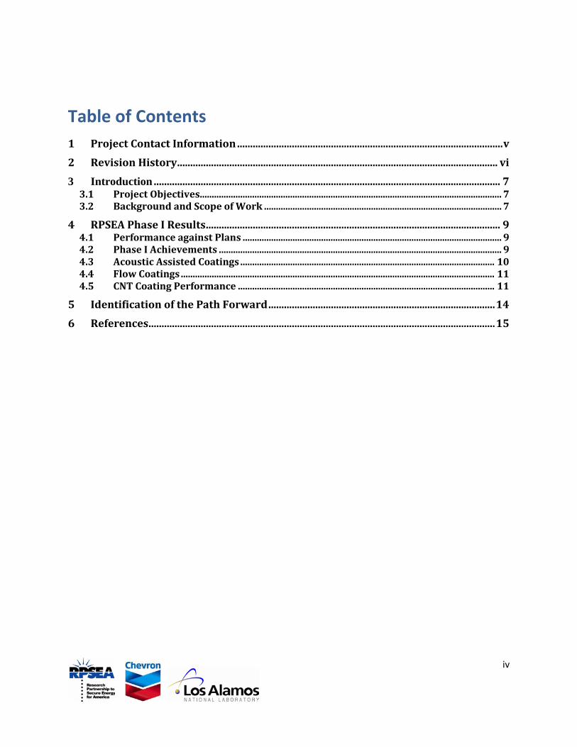
2 Revision History Revision Comment Date
- DRAFT July 25, 2012
- Original issue
A Changes include
B Changes include
C Changes include
D Changes include

7
3 Introduction This Final Report is for Phase I of the RPSEA 3300 Project, Development of Carbon
Nanotube Composite Cables for Ultra-Deepwater Oil and Gas Fields RPSEA Subcontract 09121-3300-10. The information presented in the Phase I Final Report follows from the RPSEA 3300 Statement of Work.
3.1 Project Objectives The ultimate project goal is to produce composite wires that can be wound together to
make practical under sea (and / or in-wellbore) cables able to carry the needed power for deep-sea applications. For a viable wire technology, one needs to demonstrate performance in a wire architecture that will meet wire / cable manufactures needs with production methods that can be industrially scaled and automated. As such, it is an objective of the program to develop ties with carbon nanotube (CNT) wire and cable producers in the third year of the project. The wire design pathways will attempt to meet cable-makers’ requirements and contain the following characteristics:
a) Ruggedness
b) Vibration proof
c) Chemical stability
d) Ability to withstand power surges.
e) Temperature stability (0˚C - 150˚C)
f) High pressure tolerant (300 bar)
3.2 Background and Scope of Work In order to make practical use of carbon nanotubes (CNTs) for high-performance
conductors, material handling and wire manufacturing technologies must be developed that can deal with or manipulate CNTs in very large quantities. For power transmission applications, dense structures of CNTs will need to be made that are aligned along the direction of current flow. To establish high-percolative conductivity, methodologies need to be developed that can electrically connect the tubes together in their transverse direction. This is a means to make high percolation conductivity though the entire CNT/Metal matrix ensemble.
LANL, the SUBCONTRACTOR, has available two recently developed technologies that allow for the manipulation of multiple CNT. The first was developed by Greg Goddard of Los Alamos National Laboratory called “Acoustic Flow Cytometry”. This technology manipulates small structures by using the pressure of acoustic waves of various polarizations.[2] The second technology is called “Acoustically Engineered
8
Materials” developed by Dipen Sinha of Los Alamos National Laboratory. A focus of this work is the engineering of exotic materials through the use of ultra sound.[3]
Utilizing the technologies discussed above to aid in manipulating the CNTs into practical conductors, the ultimate goal of the project over the three-year period is to increase the electrical conductivity of CNT-Copper composites to twice that of copper and then to extend the composite length to 100 meters while maintaining (or improving) other physical characteristics / physical properties. This three-year project was divided into three phases.
Phase 1 (15 months) will focus on improving electrical conductivity in short wire lengths.
Phase 2 (9 months) will develop methods to scale-up the length of the composites.
Phase 3 (12 months) will integrate and optimize these processes toward our goals of 100 meters with twice the conductivity of copper.
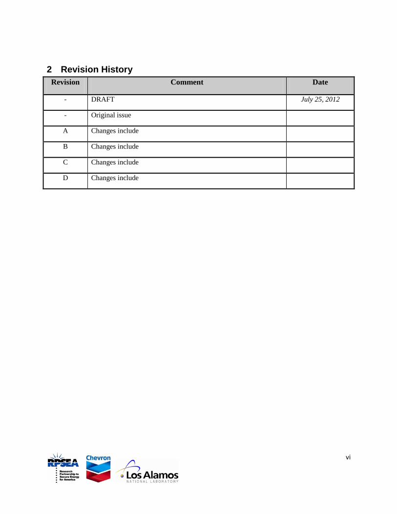
Table I below highlights Project Deliverables and Goals of each of the phases. The conductivity is the conductivity of the CNT/Metal composite wire relative to that of a pure copper conductor. A Table conductivity of 1.5 indicates a goal of 50 percent higher conductivity than pure copper. The length refers to the length in meters over which the composite is measured to have the indicated desired properties.
Table I: Project Phase Goals and Deliverables
1 1.5 0.05
Phase Conductivity Length (m)
2 1.5 50
3 2.0 100

9
4 RPSEA Phase I Results The phase I goal was to produce a 5 cm long wire having a conductivity that was 50
percent better than copper (Cu). To this end we were partially successful in meeting this Phase I milestone. We developed two scalable approaches for making composite wires that were used to make more than 100 wires that were at least 5 cm long. The best, measured resistivities of these wires fell in the range of 1.75 to 2 µΩ-cm. A typical value quoted for commercially available Cu wire is 1.76 µΩ-cm. While short of our target, the calculated CNT coating resistivities of a large number of wires were in the range of 3.5 to 50 µΩ-cm. The low range of values found for the CNT coatings’ resistivities are among the lowest resistivity values for CNT conductors reported world-wide. Furthermore, these wires are in a form amenable for manufacturing scale-up. Initial microstructural characterization showed several detrimental defects discussed below that when fixed could lead to substantial improvements in wire performance above what is reported here.
4.1 Performance against Plans The overall plans for the experimental work centered on developing a scalable wire
manufacturing process for a CNT/metal composite wire. The approach described initially was to develop a bulk alignment process in which both flow and acoustic pressure were to be used to align, concentrate, and attach CNTs to a central wire former. Due to difficulties in implementation of both flow and acoustic concentration into one process, a decision was made to work on wire fabrication processes using just acoustic assist or flow-assisted coating separately. Individually, both processes were used to make robust wires that met the Phase I deliverable length requirement. We were not able to produce a wire that had the 50 percent improvement in conductivity relative to copper. However, we did produce CNT coatings in which the coating themselves had some of the lowest reported resistivity values reported world-wide.[1] Details of the coatings are shown below. Although not achieved here, it is likely that attributes of both coating techniques will be combined in the future to produce an even more robust CNT wire-coating process.
4.2 Phase I Achievements The objectives, as discussed in section 3.1, were to make a wire that could satisfy
cable manufacturer and field-deployment demands such as handling, robustness, and stability under expected conditions of application. The implication was that both the development of a scalable, robust manufacturing method for CNT based wires along with the technology to connect the CNTs in an efficient percolative network within the wire were to be carried out in this project. These needs are reflected in milestones set for all three phases of this project.
The CNTs used in this work were grown as forests by chemical vapor deposition (CVD) at Los Alamos National Laboratory on iron-coated substrates.[4] As such, the CNTs used in this work had well-defined starting lengths. During the course of this work, we demonstrated two pathways, acoustic assist and flow coating, to producing CNT-based coatings onto wire substrates. Both coating routes can be combined to quite possibly form an even more robust wire coating process in the future. More than 100

10
wires were produced in this work that each exceeded the 5 cm piece-length requirement of Phase I. Several images of representative wires are shown in Figure 1.
4.3 Acoustic Assisted Coatings Acoustic excitation is done at a frequency in the vicinity of a high order resonance in
the tube that corresponds to concentric ring and nodal line formation along the central axis of the tube. By sweeping the excitation frequency near such a resonance the contents of the tube are consecutively agitated and concentrated near the central Cu wire leading to continual embedding of CNTs in the growing Cu coating. Difficulties were encountered with matching piezo-electric devices to the process tubes, with getting a correct dispersion of CNTs for the apparatus, and adding the solution flow to the system for concurrent operation. Of particular concern for this path is the use of surfactants. At the end of Phase I, we identified a path forward that will minimized the use of surfactants with this particular coating process. With improved matching of the acoustic transducers
Figure 1: Optical micrographs of (a) a CNT coated wire with a Cu coating, (b) a bare CNT coated wire, and (c) a close of the end of a coated wire showing the Cu core wire and CNT coating.

11
to the tube and an appropriate CNT dispersion, we plan to again put these processes together with flow and electroplating to experiment with this combined coating process.
4.4 Flow Coatings Wires dipped into a flowing CNT containing solution were coated under a set of
conditions that yielded uniform, relatively thick and dense coatings of carbon nanotubes. This method was used to make the majority of our wires in this project. This simple process of wire coating will be scaled up in Phase II for coating the long wire piece-lengths.
4.5 CNT Coating Performance Highly-aligned and dense coatings were made on wire substrates during this work.
In terms of manufacturability, this was a significant success for the Phase I work. Shown in Figure 2a is a scanning electron microscope (SEM) image of the aligned CNT fibers on the wire substrates. The CNT coatings themselves can be very dense as shown by the TEM image of Figure 2b. The latter image is from one of the thinner coatings on the wires, average thickness of 5 μm (microns). This wire was chosen for the transmission electron microscope (TEM) work because it had a thin coating and could be successfully made into a TEM foil. During the course of this work, many of the coatings had thicknesses in excess of 20 microns with some reaching to 100 microns.
The CNT coating resistivity values were obtained by calculating the parallel resistance value of the coating and wire substrate, given the dimensions of the overall wire and copper wire substrate.
1Rwire
=1
RCNT+
1RCu
(a) (b)
Figure 2: SEM image showing the aligned CNT fibers on the wire substrates. The wire axis is parallel to the bottom edge. The TEM image in (b) shows that the CNT coatings on the wires are very dense.

12
Solving for the resistivity (ρCNT
ρCNT=(Awire-ACu)*ρCu*ρwire
Awire*ρCu-ACu*ρwire
) of the CNT coating, we obtain:
The cross-sectional areas, Awire and ACu, and resistivities, ρwire and ρCu, refer to the
fully-processed coated wires and Cu wire substrates, respectively. The bare copper wires used in this work as substrates were measured yielding an average resistivity value of 1.77 μΩ-cm, which was the value used for ρCu
A subset of wires produced in this work was found to have negative calculated resistivity. These wire values were not put into Figure 3. This set of results suggests that for these wires, the two-resistor model does not apply, that there is a third layer present that has a very high resistivity and changes the cross-section areal measurements for the core wire and coating. This hypothesis is supported by some preliminary SEM and analysis. Cross-sections of a representative wire were prepared with a focused ion beam (FIB) instrument. Shown in Figure 4 is the cross-section of such a wire. The feature of interest here is the large amount of porosity present between the underlying Cu wire and
in the calculations. All measurements of wire diameters were carried out with a laser micrometer. Shown in Figure 3 is a plot of the calculated CNT coating resistivities from the wires produced in this work. A number of these values are shown in Figure 3 to be lower than the best reported resistivity values found in the literature. Although we were not able to produce wires with a lower resistivity than Cu, we did produce some of the world’s best carbon nanotube coatings in a wire form that is amenable to manufacturing and deployment in power applications.
Figure 3: Plot of the calculated wire resistivities for the CNT coatings from the wires produced in this work. The lines referencing the undoped and doped DWNT fibers represent the values reported by Zhao, et al.[1]

13
the CNT coating. This porosity is believed to be the cause of the calculated negative resistivity found for this set of wires. This porosity changes both the areas of the wire substrate and the coating used in the calculations. Note that this level of porosity was found in all places sample on the wire. There is a significant amount of Cu above the pore that came from the original wire substrate which suggests a separation within the wire substrate that is process-based. Further examination of other wires with positive calculated coating resistivities revealed some interfacial porosity within them as well, though not nearly to the extent shown in Figure 4. It is likely that interfacial defects are present in all of our wires to some extent and their elimination is expected to help in the overall performance of the wires. This will be an area for in-depth study of process-structure-property relationships in phase II as the coating technologies are scaled-up for continuous processing.
Figure 4: SEM image of the porosity found along the interface between the Cu wire substrate and CNT coating.

14
5 Identification of the Path Forward Significant progress was made towards developing a robust wire technology utilizing
carbon nanotubes. The deposition of thick coatings with scalable processes is a key step in developing a CNT-based wire technology. This is a significant success for the RPSEA work in spite of the higher than desired resistivity values for the coatings. We have identified a need for more basic research into the CNT / metal composites to better understand connectivity in these wires. It should be noted that the resistivities found for the CNT coatings themselves are some of the lowest reported around the world thus far for CNT conductors, although they are nowhere near their theoretical capability.[1] There is a need for a better material and microstructural understanding of CNT composites and the establishment of an efficient percolative network that takes advantage of the extraordinary properties of CNTs.
Based on the successes of the Phase I program, LANL advocates for moving to Phase II with the existing milestone of a 50 m wire with 50% better conductivity than Cu. LANL will pursue scale-up for long-length wires along with an increased materials and microstructural research effort for optimizing properties of the CNT / Cu composites. We believe that this approach will lead to a successful Phase II RPSEA program. With the installation of reel-to-reel processing, the coating of a 50 m wire will be demonstrated. Although the calculated resistivities for the Cu/CNT coatings are among the lowest reported world-wide, it is understood that additional research into the Cu/CNT coatings will need to be carried out to achieve resistivities lower than Cu. We will still strive to reach the goal of 50% lower resistivity compared to Cu that is part of the Phase II milestone. However, it is clear that any demonstration of an overall wire resistivity lower than Cu in a reel-to-reel processing environment is likely to attract the attention of potential wire manufacturers.

15
6 References [1] Y. Zhao, J. Wei, R. Vajtai, P. M. Ajayan, and E. V. Barrera, "Iodine doped carbon
nanotube cables exceeding specific electrical conductivity of metals," Sci. Rep., vol. 1, 2011.
[2] G. Goddard and G. Kaduchak, "Ultrasonic particle concentration in a line-driven cylindrical tube," The Journal of the Acoustical Society of America, vol. 117, pp. 3440-3447, 2005.
[3] B. Raeymaekers, C. Pantea, and D. N. Sinha, "Manipulation of diamond nanoparticles using bulk acoustic waves," Journal of Applied Physics, vol. 109, p. 014317, 2011.
[4] X. Zhang, Q. Li, T. G. Holesinger, P. N. Arendt, J. Huang, P. D. Kirven, T. G. Clapp, R. F. DePaula, X. Liao, Y. Zhao, L. Zheng, D. E. Peterson, and Y. Zhu, "Ultrastrong, Stiff, and Lightweight Carbon-Nanotube Fibers," Advanced Materials, vol. 19, pp. 4198-4201, 2007.