RPS 4000 Air Conditioner Model Trainee Manual Eng
25
© Transas Ltd. November, 2005 REFRIGERATION PLANT REFRIGERATION PLANT REFRIGERATION PLANT REFRIGERATION PLANT SIMULATOR RPS 4000 SIMULATOR RPS 4000 SIMULATOR RPS 4000 SIMULATOR RPS 4000 “AIR-CONDITIONER” MODEL TRAINEE MANUAL
-
Upload
sergioi-indurain -
Category
Documents
-
view
31 -
download
10
Transcript of RPS 4000 Air Conditioner Model Trainee Manual Eng

© Transas Ltd. November, 2005
REFRIGERATION PLANT REFRIGERATION PLANT REFRIGERATION PLANT REFRIGERATION PLANT SIMULATOR RPS 4000SIMULATOR RPS 4000SIMULATOR RPS 4000SIMULATOR RPS 4000
“AIR-CONDITIONER” MODEL TRAINEE MANUAL
© 2005 Transas Ltd. All rights reserved. The information contained herein is proprietary to Transas Ltd. and shall not be duplicated in whole or in part. The technical details contained in this manual are the best that are available at the date of issue but are subject to change without notice. Transas Ltd. pursues the policy of continuous development. This may lead to the product described in this manual being different from the product delivered after its publication. The names of actual companies and products mentioned herein may be the trademarks of their respective owners.
REFRIGERATION PLANT SIMULATOR RPS 4000. “Air-Conditioner” Model. Trainee Manual
1
This document contains:
Introduction ................................................................................................................3 Printing House Conventions.................................................................................3
Purpose of the Air Conditioning System.................................................................4 System Components .................................................................................................4 Control Panel..............................................................................................................8
Monitoring and Control of Conditioner .................................................................8 Monitoring and Control of Sea Water Supply.....................................................10 Monitoring and Control of Refrigeration Plant ....................................................12
Alarm Signals ...........................................................................................................15 Safety System ..........................................................................................................15 System Faults Introduced by the Instructor .........................................................15 Directions for the Plant Operation and Maintenance...........................................16
Procedure to Bring the Air Conditioning System into Operation in Summer Mode ................................................................................................16 Procedure to Bring the Air Conditioning System into Operation in Transient Mode...............................................................................................18 Procedure to Bring the Air Conditioning System into Operation in Winter Mode ...................................................................................................19 Refrigerant Replenishment ................................................................................19 Compressor Replenishment with Oil..................................................................20 Air Discharge from the Refrigerant System .......................................................21 Replacement if Moisture Eliminator ...................................................................22 Elimination of Compressor Damp Operation......................................................22 Breakage of Conditioner Fan .............................................................................23 Breakage of Automatic Steam Control Valve.....................................................23


Introduction
REFRIGERATION PLANT SIMULATOR RPS 4000. “Air-Conditioner” Model. Trainee Manual
3
INTRODUCTION
The simulator is designed for the training of watch keeping personnel in the correct operation of the ship’s Air Conditioning System including:
• Preparation and putting into operation of machinery and systems;
• Monitoring of their operation by the measured parameters with the assistance of the alarm system;
• Troubleshooting procedures.
In addition to the training of practical skills, the simulator allows familiarisation with fundamentals of the structure, functioning and interaction of the elements and subsystems.
The set of the simulated systems complies with the currently accepted ship standard. Parameters and performance characteristics of the modelled machinery and systems correspond to the actual ones, as the simulator models all the principal processes (thermodynamic, mechanic, gas and hydrodynamic, electrical) in their interrelation.
Printing House Conventions Sample of notation Comments
“SUMMER” To highlight names of windows, pages, buttons, etc.

Purpose of the Air Conditioning System
REFRIGERATION PLANT SIMULATOR RPS 4000. “Air-Conditioner” Model. Trainee Manual
4
PURPOSE OF THE AIR CONDITIONING SYSTEM
The central straight flow twin-channel high-pressure conditioning system is designed for the year-round moisture and temperature treatment of the air in the accommodation spaces, mess room and other rooms on the ship.
SYSTEM COMPONENTS
The system mnemonic diagram implemented in the simulator is shown in Fig. 1.
Fig. 1
The following components are included in the system and modelled in the simulator:
• System of pipelines as a hydro- and gas dynamic object;
• Refrigeration plant;
• Cooling seawater pump;
• Steam air heaters;
• Air coolers;
• Centrifugal straight flow blower with an air filter;
• Moisture control unit.
The central straight flow twin-channel high-pressure conditioning system is designed for the year-round moisture and temperature treatment of the air in the accommodation spaces, mess room and other rooms on the ship.

System Components
REFRIGERATION PLANT SIMULATOR RPS 4000. “Air-Conditioner” Model. Trainee Manual
5
The air is propelled through the conditioner by the centrifugal straight flow blower with an electric motor and air filter. When the blower is operating, its operation indicator lights up on the mnemonic diagram.
In case of the air blower breakdown, the air is supplied to the conditioning system from the air blower of the conditioner on the other side, through the shutter on the mnemonic diagram.
The plant has two steam air heaters of the first level BH1 (after the air blower) and of the second level BН2 (at the conditioner outlet), shown the top part of the mnemonic diagram.
The air temperature after the first and second levels of heaters is controlled automatically by varying the water steam feed with the use of steam control valves (direct acting temperature controls). In this case, the first stage control is adjusted for maintaining constant temperature in the first duct, whereas the setting of the second stage control varies automatically with the ambient temperature.
In case of the automatic steam control valve failure, the steam supply is controlled by using the manual control valves.
The current status of the steam control and manual control valves (degree of openness) is shown on the valves’ digital indicators on the mnemonic diagram.
At an ambient temperature of below 5°С, the treated air is saturated with water steam. The air saturator along with the demister are located after the first stage of the air heater on the mnemonic diagram.
The plant has two air coolers of the first (ВО1) and second (ВО2) stages of direct cooling. The air coolers are located in the top part of the mnemonic diagram. Installed after the air coolers are demisters.
Fig. 2
The liquid refrigerant is supplied to the air coolers via the thermostatic expansions valves – ТРВ (below the air coolers on the mnemonic diagram). The current status (degree of openness) is shown on the ТРВ digital indicator.
As the solenoid valves are opened, their open status indicators light up on the mnemonic diagram (above and below air coolers).

System Components
REFRIGERATION PLANT SIMULATOR RPS 4000. “Air-Conditioner” Model. Trainee Manual
6
The right hand part of the mnemonic diagram shows part of ship compartments serviced by the conditioner where it maintains desirable air temperature and humidity. The air parameters are controlled by using a cabin air distribution switch set in the room.
The sea water pump supplies water to the condenser and compressor cooling.
The sea water flow for the condenser cooling is controlled by using the condensing pressure control (water control valve) set on the water supply line to the condenser.
The current position (degree of openness) is shown on the digital condensing pressure indicator on the mnemonic diagram.
Flow indicators are set on the mnemonic diagram on the pipelines for the water discharge from the condenser and compressor.
At an ambient temperature of 25 and more degrees, the conditioning system switches to “SUMMER” operating mode. In this case, it is serviced by the refrigerating plant using Freon 22.
The piston eight-cylinder compressor is located in the left bottom part of the mnemonic diagram.
Fig. 3
When the compressor motor is operating, an indicator in the centre lights up, as the cylinders are brought into operation, indicators light up showing the operation of corresponding cylinder pairs in the compressor. The bottom part of the compressor on the mnemonic diagram shows the oil level in the sump.
The compressor refrigeration performance is controlled by taking its cylinders out of operation, pair by pair, on the account of electromagnetic pushing of suction valve plates with the drop of the suction pressure which varies with the change of the air coolers’ thermal load.
Electromagnetic pushing devices are controlled by the low pressure switch by means of a control system which includes a time switch.
On the charging side of the compressor, there is an oil separator with an automatic float valve for the return of oil to the compressor sump. The oil separator shows the oil level in the device.
Installed on the oil line for the return of oil to the compressor sump, are a filter, oil flow indicator and a solenoid valve which opens up at a command from the thermal switch as the temperature in the oil separator grows to 60°С.
System Components
REFRIGERATION PLANT SIMULATOR RPS 4000. “Air-Conditioner” Model. Trainee Manual
7
As the solenoid valve opens up, its indicator on the mnemonic diagram lights up.
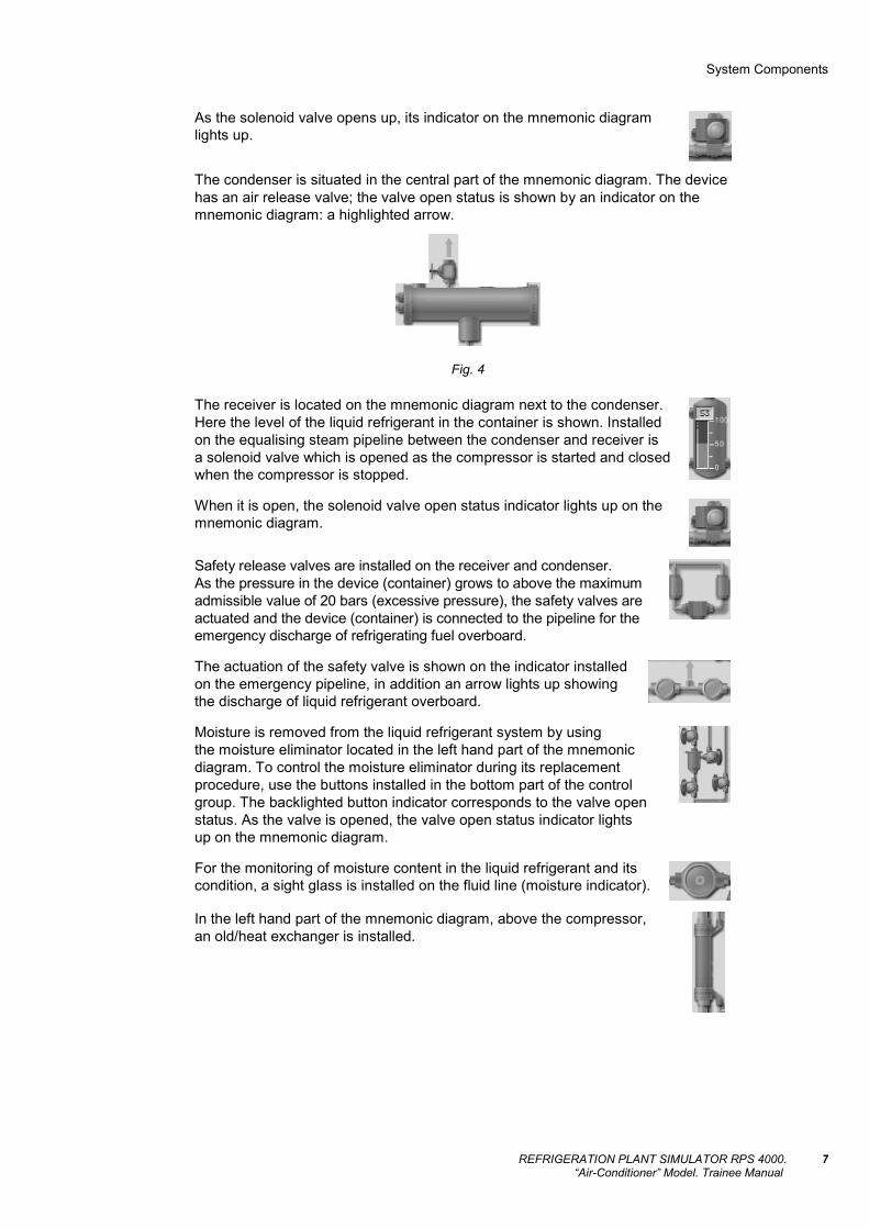
The condenser is situated in the central part of the mnemonic diagram. The device has an air release valve; the valve open status is shown by an indicator on the mnemonic diagram: a highlighted arrow.
Fig. 4
The receiver is located on the mnemonic diagram next to the condenser. Here the level of the liquid refrigerant in the container is shown. Installed on the equalising steam pipeline between the condenser and receiver is a solenoid valve which is opened as the compressor is started and closed when the compressor is stopped.
When it is open, the solenoid valve open status indicator lights up on the mnemonic diagram.
Safety release valves are installed on the receiver and condenser. As the pressure in the device (container) grows to above the maximum admissible value of 20 bars (excessive pressure), the safety valves are actuated and the device (container) is connected to the pipeline for the emergency discharge of refrigerating fuel overboard.
The actuation of the safety valve is shown on the indicator installed on the emergency pipeline, in addition an arrow lights up showing the discharge of liquid refrigerant overboard.
Moisture is removed from the liquid refrigerant system by using the moisture eliminator located in the left hand part of the mnemonic diagram. To control the moisture eliminator during its replacement procedure, use the buttons installed in the bottom part of the control group. The backlighted button indicator corresponds to the valve open status. As the valve is opened, the valve open status indicator lights up on the mnemonic diagram.
For the monitoring of moisture content in the liquid refrigerant and its condition, a sight glass is installed on the fluid line (moisture indicator).
In the left hand part of the mnemonic diagram, above the compressor, an old/heat exchanger is installed.

Control Panel
REFRIGERATION PLANT SIMULATOR RPS 4000. “Air-Conditioner” Model. Trainee Manual
8
CONTROL PANEL
The control panel located in the right hand part of the screen page contains the conditioning system monitoring and control units.
Monitoring and Control of Conditioner
Fig. 5
In the top left part of the control unit there is “POWER” indicator lamp which shows that the system is powered.
Fig. 6
Below the indicator lamp, there is “SUMMER-OFF-WINTER” conditioner operating mode switch. If the switch is set to “SUMMER” position, the conditioner operates in the summer mode providing the cooling and drying of the air. With the switch set to “OFF”, the motors of the compressor, sea water pump and fan are disconnected from the power supply. When the switch is set to “WINTER” position, the conditioner operates either in the winter mode whereby the air is heated and saturated with moisture, or in the transient ventilation mode whereby there is no treatment of the air (air heaters and saturator are turned off).
The heaters are turned on by using “HEATER1”, “HEATER2” buttons,in this case the buttons are backlighted. The buttons are installed in the left hand part of the control panel.

Control Panel
REFRIGERATION PLANT SIMULATOR RPS 4000. “Air-Conditioner” Model. Trainee Manual
9
The air temperature after the first and second levels of heaters is controlled automatically by varying the water steam feed with the use of steam control valves (direct acting temperature controls). In case of automatic steam control valve failure, the steam supply is controlled by using manual control valves.
Controls of manual “BP 1”, “BP 2” valves are installed on the control panel in the left bottom part.
Fig. 7
The automatic humidity control is performed by the steam control valve of the first stage air heater. To attain this, during the switch to the winter operating mode, the system re-adjustment is performed, i.e. the setting of the necessary ratio of the air flow to the air heater ВН1 and saturator by using the manual control valve located above the air saturator on the mnemonic diagram. The air saturator control valve is adjusted by using “H2O” setter located on the control panel next to “BP 1” and “BP 2”.
The current valve status is shown on the digital indicator on the mnemonic diagram.
Below the conditioner operating mode switch on the control panel there is a digital pressure gauge which shows pressure of the water steam fed to the system.
Fig. 8
In the right hand part of the control panel there are three temperature gauges for the display of ambient temperature “AMBIENT AIR”, air temperature in the first duct – “DUCT 1” and in the second duct – “DUCT 2”.
Fig. 9

Control Panel
REFRIGERATION PLANT SIMULATOR RPS 4000. “Air-Conditioner” Model. Trainee Manual
10
Located below the temperature gauges are devices for the display of the air relative humidity in the first and second ducts.
Fig. 10
To the left of the thermostatic controls installed on the control panel are digital setters of thermal switches monitoring the air temperature after the first and second air coolers and controlling the operation of solenoid valves at the supply and return of liquid refrigerant from the air coolers.
Fig. 11
The air parameters are controlled by using a cabin air distribution switch set in the room.
The current air temperature and humidity in the room is shown on the indicator set above the switch on the mnemonic diagram.
Fig. 12
Monitoring and Control of Sea Water Supply The sea water pump supplies water to the condenser and compressor cooling.
Fig. 13

Control Panel
REFRIGERATION PLANT SIMULATOR RPS 4000. “Air-Conditioner” Model. Trainee Manual
11
To start the system operating it is first necessary to press “VALVE” button in the bottom part of the panel in order to open the valve for the supply of water to the compressor cooling.
As the valve is opened, the button indicator is backlighted and the valve open status indicator lights up on the mnemonic diagram (below the compressor).
Then turn on the sea water pump by using “ON/OFF” button on the control panel: the button indicator is backlighted. The pump ON indicator lights up on the mnemonic diagram.
The sea water pump supplies to the condenser and compressor cooling.
The sea water flow for the condenser cooling is controlled by using the condensing pressure control (water control valve) set on the water supply line to the condenser.
With the pump’s charging pressure low, an alarm is generated, and an appropriate lamp starts flickering in the bottom part of the screen.
To the right of the pressure gauge on the control panel, there are temperature gauges showing sea water temperature – “INLET” and temperature of the water removed from the condenser – “OUTLET”.
The sea water flow for the condenser cooling is controlled by using the condensing pressure control (water control valve) set on the water supply line to the condenser.
“PRESSURE SET” unit for the control of the water control valve for maintaining a certain condensing pressure (8 ÷ 11 bars) is in the centre of the control panel.
Fig. 14
The current position (degree of openness) is shown on the digital condensing pressure indicator on the mnemonic diagram.
Control Panel
REFRIGERATION PLANT SIMULATOR RPS 4000. “Air-Conditioner” Model. Trainee Manual
12
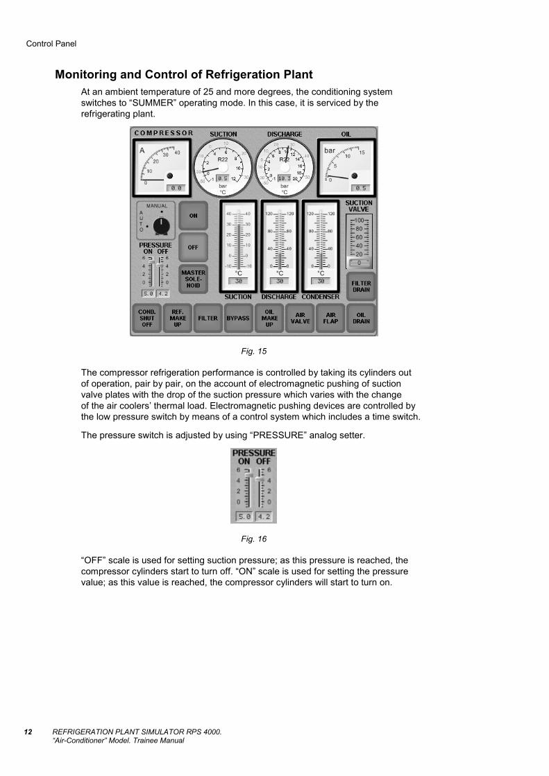
Monitoring and Control of Refrigeration Plant At an ambient temperature of 25 and more degrees, the conditioning system switches to “SUMMER” operating mode. In this case, it is serviced by the refrigerating plant.
Fig. 15
The compressor refrigeration performance is controlled by taking its cylinders out of operation, pair by pair, on the account of electromagnetic pushing of suction valve plates with the drop of the suction pressure which varies with the change of the air coolers’ thermal load. Electromagnetic pushing devices are controlled by the low pressure switch by means of a control system which includes a time switch.
The pressure switch is adjusted by using “PRESSURE” analog setter.
Fig. 16
“OFF” scale is used for setting suction pressure; as this pressure is reached, the compressor cylinders start to turn off. “ON” scale is used for setting the pressure value; as this value is reached, the compressor cylinders will start to turn on.
Control Panel
REFRIGERATION PLANT SIMULATOR RPS 4000. “Air-Conditioner” Model. Trainee Manual
13
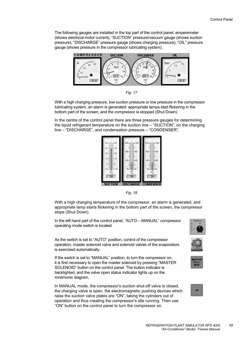
The following gauges are installed in the top part of the control panel: amperemeter (shows electrical motor current), “SUCTION” pressure/vacuum gauge (shows suction pressure), “DISCHARGE” pressure gauge (shows charging pressure), “OIL” pressure gauge (shows pressure in the compressor lubricating system).
Fig. 17
With a high charging pressure, low suction pressure or low pressure in the compressor lubricating system, an alarm is generated: appropriate lamps start flickering in the bottom part of the screen, and the compressor is stopped (Shut Down).
In the centre of the control panel there are three pressure gauges for determining the liquid refrigerant temperature on the suction line – “SUCTION”, on the charging line – “DISCHARGE”, and condensation pressure – “CONDENSER”.
Fig. 18
With a high charging temperature of the compressor, an alarm is generated, and appropriate lamp starts flickering in the bottom part of the screen, the compressor stops (Shut Down).
In the left hand part of the control panel, “AUTO – MANUAL” compressor operating mode switch is located.
As the switch is set to “AUTO” position, control of the compressor operation, master solenoid valve and solenoid valves of the evaporators is exercised automatically.
If the switch is set to “MANUAL” position, to turn the compressor on, it is first necessary to open the master solenoid by pressing “MASTER SOLENOID” button on the control panel. The button indicator is backlighted, and the valve open status indicator lights up on the mnemonic diagram.
In MANUAL mode, the compressor’s suction shut-off valve is closed, the charging valve is open, the electromagnetic pushing devices which raise the suction valve plates are “ON”, taking the cylinders out of operation and thus creating the compressor’s idle running. Then use “ON” button on the control panel to turn the compressor on.

Control Panel
REFRIGERATION PLANT SIMULATOR RPS 4000. “Air-Conditioner” Model. Trainee Manual
14
After the compressor has been started, the evaporator solenoid valves open up, in several seconds the pushing devices are activated, and its cylinders start operating. On the mnemonic diagram cylinder operation indicators light up. The suction valve of the compressor is opened via “SUCTION VALVE” setter in the right hand part of the control panel.
Fig. 19
The current position (degree of openness) is shown on the digital indicator of the suction valve on the mnemonic diagram.
“OFF” button on the control panel serves for turning the compressor off when the operating mode switch is set to “MANUAL”. As this is done, evaporator solenoid valves are closed.
The air valve is controlled via “AIR VALVE” button. The backlighted button indicator corresponds to the valve’s open status.
“FILTER DRAIN” button serves for the control of the valve on the liquid refrigerant exhaust line from the moisture eliminator.
“FILTER” button serves for the control of the moisture eliminator shut-off valve.
“BYPASS” button serves for the control of the moisture eliminator bypass valve.
For the monitoring of moisture content in the liquid refrigerant and its condition, a sight glass is installed on the fluid line (moisture indicator).
In the bottom part of the unit valve control buttons are located.
The backlighted button indicator corresponds to the valve’s open status. As the valve opens, the valve open status indicator lights up on the mnemonic diagram.
Button for the control of the shut-off valves on the liquid refrigerant drain from the receiver.
Button for the control of the valve for the system replenishment with liquid refrigerant.
Button for the control of the valve for the supply of oil into the compressor.
Button for the control of the air flap.

Alarm Signals
REFRIGERATION PLANT SIMULATOR RPS 4000. “Air-Conditioner” Model. Trainee Manual
15
ALARM SIGNALS
• Low Press. Compr. Inlet – low compressor suction pressure;
• High Press. Compr. Outlet – high compressor charging pressure;
• Low Press. Lub. Oil – low pressure of compressor lubricating oil;
• High T Compr. Outlet – high temperature on the compressor charging side;
• Low Level Compr. Oil – low lubricating oil level in the compressor;
• Low Press. Cool. Water – low pressure of cooling (Sea) water;
• Solenoid Closed – master solenoid is closed;
• Steam opened – steam supply is open;
• Compressor Shut Down.
SAFETY SYSTEM
Not available as an individual device (system). It is implemented owing to the system automatics: shutdown of the refrigerating plant compressor in case of e.g. high charging pressure and temperature, low suction pressure of lubricating oil pressure.
SYSTEM FAULTS INTRODUCED BY THE INSTRUCTOR
• Condenser Fouling;
• Term. Exp. Valve 1 Fouling;
• Term. Exp. Valve 2 Fouling;
• Excessive moisture in Filter;
• Air in System;
• Ref. Power fault;
• Refrigerant leakage;
• Ventilation fault – air blower will not start;
• Air Filter fouling;
• Water Steam Reg.1 fault – faulty control 1, full opening of steam valve;
• Water Steam Reg.2 fault – faulty control 2, full opening of steam valve;
• Automatic Oil drain fault – faulty oil separator, air supply is reduced;
• High Pressure Pressostat fault – faulty pressostat, high pressure protection does not operate;
• Oil Leakage – oil leakage from the compressor;
• SW Reg. Valve Fault – faulty sea water valve, control for maintaining pressure in the condenser does not operate.

Directions for the Plant Operation and Maintenance
REFRIGERATION PLANT SIMULATOR RPS 4000. “Air-Conditioner” Model. Trainee Manual
16
DIRECTIONS FOR THE PLANT OPERATION AND MAINTENANCE
Procedure to Bring the Air Conditioning System into Operation in Summer Mode
The air conditioning system is switched to the summer mode as the ambient temperature grows to +25°С:
1. Set the conditioner operating mode switch to “SUMMER” position.
Fig. 20
2. Open the valve for feeding water to the compressors cooling.
3. Turn on the sea water pump.
Fig. 21
4. Open the shut-off valves on the liquid refrigerant circulation lines.
5. Adjust temperature switches.
Fig. 22

Directions for the Plant Operation and Maintenance
REFRIGERATION PLANT SIMULATOR RPS 4000. “Air-Conditioner” Model. Trainee Manual
17
6. Set the compressors operating mode switch to “MANUAL” position.
7. Adjust the low pressure switch.
Fig. 23
On “OFF” scale, set the suction pressure value whereupon, with some delay, the compressor cylinders will start to turn off. On “ON” scale, set the pressure value whereupon the compressor cylinders will start to turn on, by the timer, too.
8. Open the master solenoid valve.
9. Check if the compressor suction valve is closed.
Fig. 24
10. Run the compressor.
As this is done, the electromagnetic actuators which raise the suction valve plates are “ON”, taking the cylinders out of operation and thus creating the compressor’s idle running.
After the compressor has been run, the pushing devices are turned off in several seconds, and its cylinders start operating:
1. Partly open (to 5–10%) the compressor suction valve.
Fig. 25
Directions for the Plant Operation and Maintenance
REFRIGERATION PLANT SIMULATOR RPS 4000. “Air-Conditioner” Model. Trainee Manual
18
2. Check pressure in the compressor lubricating system.
Fig. 26
3. With normal oil pressure value, continue opening the suction valve observing safety precautions.
4. Set the compressor operating mode switch to “AUTO” position.
5. Use manual switches to set the desired air temperature in the cabins.
6. Use manual switches to set the desired air temperature in the cabins.
Values of temperature and humidity in the cabin are shown on indicators.
Fig. 27
7. Monitor the plant operating parameters maintaining their values within a standard range. The alarm system will signal about all the possible faults.
As the monitored parameter reaches its limit value, an appropriate alarm lights up in the bottom part of the screen. Where no steps are made to normalise the compressor operation, “SHUT DOWN” protection is actuated, and the compressor is stopped, whereafter it can be brought back into operation in “MANUAL” mode only.
Procedure to Bring the Air Conditioning System into Operation in Transient Mode
The air conditioning system is switched to the transient mode at the ambient temperature for +15°С to +25°С.
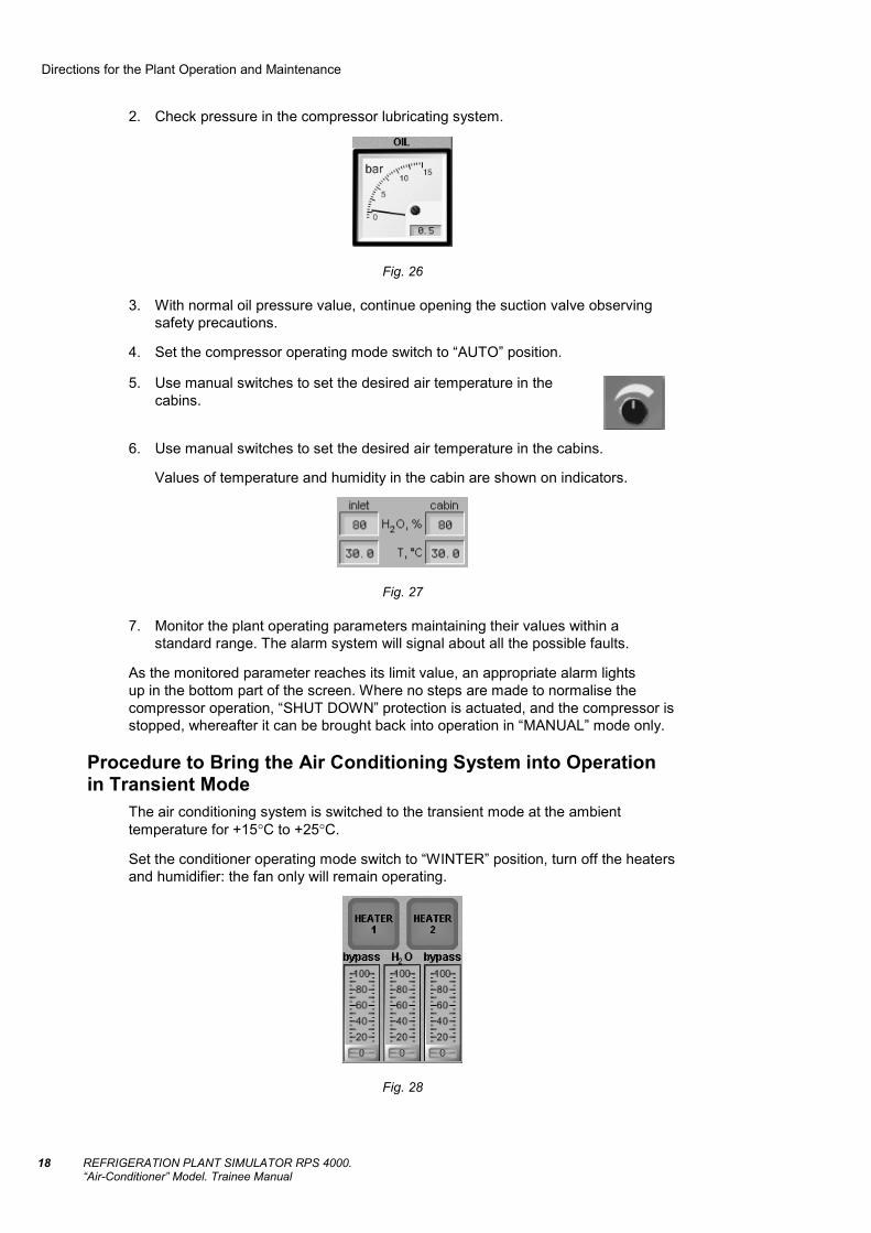
Set the conditioner operating mode switch to “WINTER” position, turn off the heaters and humidifier: the fan only will remain operating.
Fig. 28

Directions for the Plant Operation and Maintenance
REFRIGERATION PLANT SIMULATOR RPS 4000. “Air-Conditioner” Model. Trainee Manual
19
Procedure to Bring the Air Conditioning System into Operation in Winter Mode
The air conditioning system is switched to the winter operating mode when the ambient temperature drops to +15°С:
1. Set the conditioner operating mode switch to “WINTER” position.
2. Depending on the ambient temperature (tн), turn on the first and second stage heaters.
Ambient temperature after the first and second stage heaters, as well as relative humidity of the treated air is maintained automatically by using the direct-acting temperature controls (steam control valves). In this case, the first stage control maintains constant temperature at the first duct outlet, whereas the second stage control maintains temperature at the second duct outlet in accordance with its setting changed automatically with the ambient temperature.
3. To control the air humidity, it is first necessary to turn on “H2O” valve manually monitoring the air humidity values in the first and second ducts. After it has been set, humidity is controlled automatically in accordance with the ambient temperature by the first duct temperature control.
Fig. 29
4. Use manual switches in the cabin to set the desired temperature in the cabin.
5. Monitor the air conditioner operation parameters maintaining their values within the standard range.
Refrigerant Replenishment The operation is performed if the refrigeration plant operating mode indicates insufficient refrigerant in the system (low refrigerant level in the receiver, gas bubbles in the sight glass, low suction pressure, excessive heating in the suction line and high temperature on the charging line):
1. Set the compressor operating mode switch to “MANUAL” position.
2. Close the shut-off valve on the liquid line after the receiver.
3. Open the make-up valve.
4. Monitor the refrigerant level by the sight glass on the receiver.

Directions for the Plant Operation and Maintenance
REFRIGERATION PLANT SIMULATOR RPS 4000. “Air-Conditioner” Model. Trainee Manual
20
5. After the end of the process, close the make-up valve (the refrigerant level on the receiver sight glass is 50%).
6. Open the shut-off valve after the receiver.
7. Set the operating mode switch to “AUTO” position.
8. Monitor the refrigerating plant operation parameters.
9. In case of the system overfilling with liquid refrigerant, there may be “damp” compressor operation.
Compressor Replenishment with Oil This is performed if the oil level in the sight glass on the compressor sump has dropped to below ½ height mark. The oil should best be added with the compressor not running (oil level is clearly visible in the sight glass):
1. Set the compressor operating mode switch to “MANUAL” position.
2. Close the compressor suction valve.
3. After the suction pressure (in the sump) has dropped to a value below the atmospheric pressure (≅-0.5 bars), stop the compressor.
4. Open the oil make-up valve.
5. After the end of the process (oil level is not higher than 2/3 of the sight glass), close the valve.
6. Turn the compressor on.
7. Open the compressor suction valve.
Fig. 30
8. Set the operating mode switch to “AUTO” position.
9. Monitor the refrigerating plant operating parameters.
Directions for the Plant Operation and Maintenance
REFRIGERATION PLANT SIMULATOR RPS 4000. “Air-Conditioner” Model. Trainee Manual
21
Air Discharge from the Refrigerant System This is performed if the pressure gauge needle on the charging line makes jerking oscillatory motions, and the charging pressure exceeds the optimum value by 2 bars or more:
1. Set the compressor operating mode switch to “MANUAL” position.
2. Close the compressor suction valve.
3. Turn the compressor off.
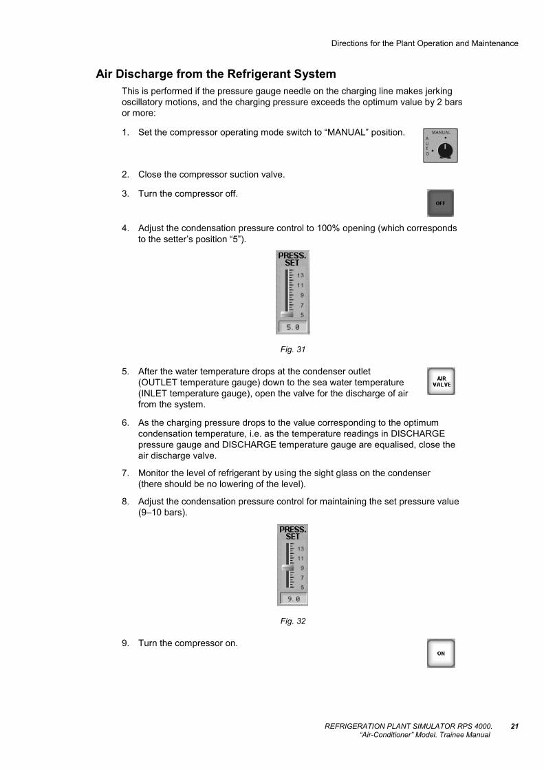
4. Adjust the condensation pressure control to 100% opening (which corresponds to the setter’s position “5”).
Fig. 31
5. After the water temperature drops at the condenser outlet (OUTLET temperature gauge) down to the sea water temperature (INLET temperature gauge), open the valve for the discharge of air from the system.
6. As the charging pressure drops to the value corresponding to the optimum condensation temperature, i.e. as the temperature readings in DISCHARGE pressure gauge and DISCHARGE temperature gauge are equalised, close the air discharge valve.
7. Monitor the level of refrigerant by using the sight glass on the condenser (there should be no lowering of the level).
8. Adjust the condensation pressure control for maintaining the set pressure value (9–10 bars).
Fig. 32
9. Turn the compressor on.

Directions for the Plant Operation and Maintenance
REFRIGERATION PLANT SIMULATOR RPS 4000. “Air-Conditioner” Model. Trainee Manual
22
10. Open the compressor suction valve.
11. Set the operating mode switch to “AUTO” position.
Replacement if Moisture Eliminator This is done when the colour of the sight glass indicator changes. The indicator colour changes from green to yellow as the moisture penetrates in the refrigerant system:
1. Close the moisture eliminator shut-off valves.
2. Open the moisture eliminator bypass valve.
3. Open the valve for drawing off refrigerant from the moisture eliminator for several minutes (1–2 minutes).
4. Close the valve for drawing off refrigerant from the moisture eliminator.
5. Open the moisture eliminator shut-off valves.
6. Close the moisture eliminator bypass valve.
As this is done, the indicator colour will change from yellow to green, i.e. there will be an imitation of the moisture eliminator replacement.
Elimination of Compressor Damp Operation This is performed if there is a sharp drop of temperature on the charging line (down to +10–0°С), overheating decreases, the compressor noise changes to dull, the cylinder walls and sump are covered with ice (if there is considerable flooding with liquid refrigerant), rattling noise appears, and the amperemeter needle goes beyond the red line:
1. Close the compressor suction valve leaving it 5–10% open.
Fig. 33
2. After the indications of damp operation disappear, open the compressor suction valve slowly.
3. Check oil level in the sump replenish the compressor with oil as required.

Directions for the Plant Operation and Maintenance
REFRIGERATION PLANT SIMULATOR RPS 4000. “Air-Conditioner” Model. Trainee Manual
23
Breakage of Conditioner Fan If a fan is broken, air is supplied to this conditioner by the fan of the conditioner on the other board through the air flap.
To do this, press the air flap control button.
You can act in much the same way in case of the fan air filter fouling until it is “replaced” (the fault is eliminated from the instructor workplace).
Breakage of Automatic Steam Control Valve If the automatic steam control valve is broken:
1. Close steam control “Bypass 1” and “Bypass 2” shut-off valves (for the time of the repairs).
Fig. 34
2. Open the manual control valve on the bypass line, adjusting its flow by the readings of temperature gauges at the outlets of the first and second ducts.
Fig. 35