Router Adjustment Systemgo.rockler.com/tech/RTD10000562AC.pdfINSTRUCTIONS 1 Router Adjustment System...
8
INSTRUCTIONS 1 Router Adjustment System Stock No. 40-150 Congratulations on your ProLift purchase! As the market’s premier router lift, the ProLift is specifically designed to make adjusting and changing router bits fast, easy, convenient, and safe. Moreover, it allows you to fine-adjust your bits and zero out your setting from any bit height — all from above the router table! Please carefully follow these simple instructions, maintenance guidelines, and usage tips to get started safely and ensure optimal performance for years to come. (28827) RTD10000562AC
Transcript of Router Adjustment Systemgo.rockler.com/tech/RTD10000562AC.pdfINSTRUCTIONS 1 Router Adjustment System...

IN
ST
RU
CT
IO
NS
1
Router Adjustment System
Stock No. 40-150
Congratulations on your ProLift purchase! As the market’s premier router lift, the ProLift is specifically designed to make adjusting and changing router bits fast, easy, convenient, and safe. Moreover, it allows you to fine-adjust your bits and zero out your setting from any bit height — all from above the router table!
Please carefully follow these simple instructions, maintenance guidelines, and usage tips to get started safely and ensure optimal performance for years to come.
(28827)
RTD10000562AC

2
1 ProLift 1 2 Column Locking Knob and Spring 1 3 Starting Pin (Not Shown) 1 4 Fine Adjustment Dial Assembly 1 5 Custom Speed Wrench 1 6 Hex Wrench (Not Shown) 1 7 11⁄2” Insert with (3) Mounting Screws 1 8 1/4-20 Plate Mounting Screws (Not Shown) 2
PARTS LIST
7
4
5
1
2

3
ProLift Assembly 1. Slowly tighten the housing’s
middle bolt, gradually spreading the housing apart
until your router will fit. Do not overspread the housing.
The spreader gap must NOT exceed 3/8".
Important: Porter-Cable routers have (4) locating
pins. Align these pins with the grooves machined into the ProLift housing (and motor adapters).
2. Slide your router motor into the housing. For PC 7518/19
motors leave approximately 1.5" of protrusion. Fig. 2a. Note: Router motors smaller than 4.2" in diameter require
a separate adapter component. Refer to the Adapter
Appendix (below) to find the appropriate adapter.
Fig. 1
Fig. 2a
11⁄2"
11⁄2"
Use this information to find the router adapter you need. Be sure to read any notes that may apply.Important installation note for ALL adapters: Do not align the two gaps in the adapter with the spreader gap in the ProLift housing.
4.2" to 3.2175" adapter (40-003):Makita RF11000/01 series
4.2" to 3.270" adapter (40-078):Hitachi M12VC
4.2" to 3.5" adapter (40-002): Porter-Cable 690/890 series Bosch 1617/18 series DeWalt 610/616/618 series
Note for Porter-Cable 890 routers: You must first remove the factory height adjustment rack from the motor housing.
Note for DeWalt 610 routers: You must first remove the factory height adjustment rack from the motor housing. Also, be sure to use the factory supplied stainless steel shim that wraps around the motor housing. Avoid kinks in the shim before placing the adapters around the motor.
ADAPTER APPENDIX
4
Fig. 3
Fig. 4
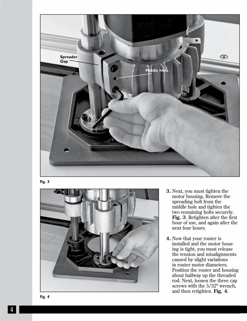
3. Next, you must tighten the motor housing. Remove the spreading bolt from the
middle hole and tighten the two remaining bolts securely. Fig. 3. Retighten after the first
hour of use, and again after the next four hours.
4. Now that your router is installed and the motor hous-ing is tight, you must release the tension and misalignments caused by slight variations in router motor diameters. Position the router and housing about halfway up the threaded rod. Next, loosen the three cap screws with the 5/32" wrench, and then retighten. Fig. 4.
Middle Hole
Spreader Gap

5
Fig. 5
Fig. 6
Retighten after the first hour of use, and again after the next four hours.
Note: If any of the bolts should ever become detached, be sure to properly reassemble the washers.
5. Screw the column locking knob (t-knob with brass stud and spring) into place. Fig. 5.
6. Drop the assembled ProLift and router motor into your router table’s opening. Fig. 6. Secure the lift with the pair of 1/4-20 plate mounting screws included with your ProLift.
Column Lock Knob

Fig. 7
Fig. 8
Fig. 9
Fig. 10
Engraved Line
4
Socket
Column Lock
Starting Pin
6
Using Your ProLiftAdjusting Bit HeightThis is done from the top of the table using the 9/16" deep well socket and speed wrench. Turning the socket clockwise will raise the router. To “zero-out” the fine adjuster, simply take up the socket slack in the direction you’re planning to rotate, and spin the adjuster around the socket until the zero lines up with the engraved line on the plate Fig. 7. The socket must not turn during this step. One revolution raises or lowers the lift exactly 1/8". The seven short engravings to the left and right of the zero mark represent .0025".
Changing Router BitsAfter removing plastic insert ring raise the bit until it protrudes out the top Fig. 8.
Inter-Loc InsertsInstall the 11⁄2" plastic insert using the three screws provided.
Using the Column Lock KnobUse the column lock to preserve your setting from accidental movement, and to prevent backdriving during extreme vibration Fig. 9. It will even prevent backdriving if your preload nut is out of adjustment or worn out. Always use the column lock knob when operating the router for extended periods of time at full speed.
Using the Starting PinStock is most vulnerable to catching the bit and being thrown at the beginning of your cut, before it engages the router bit guide bearing. Using a starting pin reduces this possibility. Be sure the pin is screwed in tightly before use. Fig. 10.

7
Fig. 11
Fig. 12
Fig. 13
Router Motor Housing Bolts
Column Mounting Bolts
Router Motor Housing Bolts
ColumnColumn
Acme Threaded Rod
Backlash Adjustment Knob
Maintaining the ProLiftTightening BoltsDuring the break-in period you must retighten all the bolts after one hour, and again after four more hours of use. Periodically check all bolts to ensure they are tight, especially the three column mounting bolts and two router motor housing bolts. Fig. 11. This should be done at least every 20 hours of use.
Managing GreaseAt least once a year (more if needed) remove the grease from the columns and acme threaded rod. WD-40 and a brush will make the job easier. Reapply a good quality multi-purpose grease (such as white lithium) to the acme rod and columns. Fig. 12. Wipe off excess grease. Keeping up with this step will greatly increase the life of your ProLift. Cleaning your Router Use an air hose or vacuum to keep your router motor as clean as possible. Never walk away from your router without confirming it’s clean and free from dust and debris and the potential for fire.
Backlash AdjustmentAfter a fair amount of wear the anti-backlash nut may need adjustment. If your router back drives downward you know it’s time to adjust the preload nut. To do so, simply tighten the three preload screws 1/4 turn. Fig. 13.
Dust CollectionDust collection in your cabinetand at the fence will dramatically reduce the amount of dust and debris build-up on your ProLift.It will also ensure your router runs cooler, and will make maintaining your ProLift much easier.

8
Important Safety PointsBefore operating your router table please read this manual thoroughly. Safety and use tips are contained in the manual. This page is not the sole source of safety information. Retain the manual for future reference. Refer to your router owner’s manual for safety instructions regarding use of that tool. This manual is not an instruction book on how to do woodwork-ing with a power tool. We encourage all woodworkers to continually seek improvement in their woodworking skills, regardless of their craftsmanship or years of experience. The router table, fence and accessories must only be used for their intended purpose: woodworking via normal routing operations. “Normal operations” means basic shaping of wood in conditions where grounded electricity, sharp tools, dust, and rapidly spinning parts can be used or encountered safely. The following instructions elaborate on this concept.
1. Do not use your ProLift free handed, only use when mounted in a quality and robust router table.2. Make sure all power cords are clear of the ProLift components.3. Your router bits must never contact the router bit reduction rings.4. Keep work area clean, dry and well lit.5. The hardware affixing the insert to the routertop must be installed for safe use. Tighten insert hold-down screws before each use.6. Use the right tool for the job. Do not force a tool or attachment to do a job for which it was not designed.7. Safe operation requires a router table fence, bit guard, dust collection system, starting pin or fulcrum, and speed reducer for large diameter bits. You must reduce the router speed for 1” or larger diameter bits. Consult your router bit manufacturer for the speed reduction data.8. Use the right tool for the job. Do not force a tool or attachment to do a job for which it was not designed.9. Secure your work with a featherboard, clamps, or a vice when appropriate. The use of inappropriate accessories may cause injury.10. Wear safety glasses, dust mask, face shield and ear protection. This is not an exhaustive list. Every-day eye glasses do not substitute for safety glasses.11. Do not wear gloves or jewelry while using a power tool and ProTop.12. Maintain your equipment and its accessories in good working condition. Look for wear, poor alignment of moving parts, binding of moving parts, breakage, poor mounting, or other conditions that may affect operation and safety. Repair or replace any damaged parts.13. Disconnect the power before moving, adjusting, or repairing parts, or otherwise maintaining your router table and any accessories you may be using.14. Keep children, pets, and those who may disregard safety away from work area, cords, sockets and tools.15. Wear snug fitting clothes and keep long hair back to avoid catching in moving parts.16. Do not overreach. Maintain balanced footing and stance.17. Stay alert. Use common sense.
LIMITED TWO-YEAR WARRANTYWe make every effort to assure that our products meet quality and durability standards, and warrant to the original retail purchaser that this product is free from defects in materials and workmanship for two years. Remedy shall be limited to Bench Dog’s choice of repair, replacement or refund. This warranty does not provide remedy for consequential economic loss.
This is a limited two-year warranty. It requires the purchaser to contact Bench Dog in writing within 30 days of discover-ing the defect. Warranty does not apply to defects due directly or indirectly to misuse, abuse, negligence or accidents, repairs or alterations, or due to lack of maintenance. It excludes components and parts not manufactured by Bench Dog, defects caused by failure to provide a suitable installation environment, and damage caused by use for purposes other than those for which the product was designed. Bench Dog, Inc. reserves the right to make product changes without notice and without obligation to make these changes on products previously sold. It excludes warranties of fitness for a particular purpose.
If the product is defective, we reserve the right to fix it, replace it, or refund the cost of the product to you. Typically, this results in a refund. All claims are limited to the two-year claims period. We must receive the product before a credit or refund will be issued. The warranty language on the product or in the product’s manual may contain additional limita-tions, which govern.
If you wish to return something, call the dealer where you purchased the product. If you wish to return something purchased from Bench Dog directly, call 1-800-786-8902 to receive an RMA number. Upon receipt and inspection of the goods, a credit or replacement will be issued for defective products. Return of nondefective items to Bench Dog are sub-ject to a 7% restocking charge. This is necessary due to the cost of checking, repackaging, and inventorying the stock.
BENCH DOG DISCLAIMS AND BUYER EXPRESSLY WAIVES ANY AND ALL WARRANTIES, EXPRESS OR IMPLIED, INCLUDING BUT NOT LIMITED TO, IMPLIED CONDITIONS OF FITNESS FOR A PARTICULAR PURPOSE, MERCHANTABILITY, OR ANY OTHER MATTER.