Route Optimization Method of UAV Autonomous Transmission ...
4
* Corresponding author: [email protected] Route Optimization Method of UAV Autonomous Transmission Line Detection Based on Beidou Positioning Service Wenjun Cui 1 , Tao Wang 1 , Lifeng Cai 1 , Yanhua Zhang 1,* and Jiaxin Zhang 2 1 State Grid Chaoyang Electric Power Supply Company, 122000 Liaoning, China 2 State Grid Liaoning Electric Power Co., Ltd., 110004 Liaoning, China Abstract: By using Beidou high-precision positioning technology, drone autonomous flight technology, and drone communication technology, a drone inspection system has been constructed. In order to further improve the work efficiency of UAV inspection on transmission lines, a single-base tower UAV inspection track optimization method based on the filtering method of the sphere unit limit is proposed. With the assistance of precision positioning services, the autonomous drone inspection hovering accuracy can reach an average of 5cm (E-W), 6cm (N-S), and 7cm (H), which meets the requirements of fine line inspections. The method proposed in this paper can further improve the efficiency of UAV fine independent inspection while improving the intelligent level of transmission line inspection. 1 Introduction Unmanned Aerial Vehicle (UAV) is widely used in the operation of remote, dangerous and complex area because of its advantages of small volume, low price, easy to control and flexible. By carrying all kinds of sensors, it can carry out inspection and inspection of power equipment all day long, all-round and flexible[1-2]. As the UAV application unfolds, some problems have been exposed. For example, when applying UAV inspection, UAV needs professional manual operation, which greatly reduces the generality of UAV inspection. Although UAV has route planning function, some companies or scholars use route planning function to realize autonomous inspection function [3-5]. The key of UAV autonomous inspection lies in making UAV patrol track in advance, combining with UAV flight safety, shooting distance and other constraints to carry out track planning[6,7]. Under this background, this paper takes single base tower as the basic unit and optimizes the track according to the characteristics of the track. The method proposed in this paper can further improve the efficiency of UAV fine independent inspection while improving the intelligent level of transmission line inspection. 2 Implementation scheme of autonomous drone inspection based on Beidou high-precision positioning technology 2.1 Overall structure This system deeply researches the standardized inspection path of UAV substations, autonomous control system of UAV, communication mechanism of UAV control and management method of autonomous UAV inspection results, forming UAV on-duty autonomy in UAV substations inspection system. It includes UAV inspection path planning standards and acquisition verification, UAV autonomous flight control system, UAV and application platform communication control, UAV inspection results identification and management. As shown in Figure 1. Figure 1. Overall architecture of Beidou high-precision position service in substation autonomous UAV inspection E3S Web of Conferences 267, 01055 (2021) ICESCE 2021 https://doi.org/10.1051/e3sconf/202126701055 © The Authors, published by EDP Sciences. This is an open access article distributed under the terms of the Creative Commons Attribution License 4.0 (http://creativecommons.org/licenses/by/4.0/).
Transcript of Route Optimization Method of UAV Autonomous Transmission ...
* Corresponding author: [email protected]
Route Optimization Method of UAV Autonomous Transmission Line Detection Based on Beidou Positioning Service
Wenjun Cui1, Tao Wang1, Lifeng Cai1, Yanhua Zhang1,* and Jiaxin Zhang2
1State Grid Chaoyang Electric Power Supply Company, 122000 Liaoning, China 2State Grid Liaoning Electric Power Co., Ltd., 110004 Liaoning, China
Abstract: By using Beidou high-precision positioning technology, drone autonomous flight technology, and drone communication technology, a drone inspection system has been constructed. In order to further improve the work efficiency of UAV inspection on transmission lines, a single-base tower UAV inspection track optimization method based on the filtering method of the sphere unit limit is proposed. With the assistance of precision positioning services, the autonomous drone inspection hovering accuracy can reach an average of 5cm (E-W), 6cm (N-S), and 7cm (H), which meets the requirements of fine line inspections. The method proposed in this paper can further improve the efficiency of UAV fine independent inspection while improving the intelligent level of transmission line inspection.
1 Introduction
Unmanned Aerial Vehicle (UAV) is widely used in the operation of remote, dangerous and complex area because of its advantages of small volume, low price, easy to control and flexible. By carrying all kinds of sensors, it can carry out inspection and inspection of power equipment all day long, all-round and flexible[1-2]. As the UAV application unfolds, some problems have been exposed. For example, when applying UAV inspection, UAV needs professional manual operation, which greatly reduces the generality of UAV inspection. Although UAV has route planning function, some companies or scholars use route planning function to realize autonomous inspection function [3-5]. The key of UAV autonomous inspection lies in making UAV patrol track in advance, combining with UAV flight safety, shooting distance and other constraints to carry out track planning[6,7]. Under this background, this paper takes single base tower as the basic unit and optimizes the track according to the characteristics of the track. The method proposed in this paper can further improve the efficiency of UAV fine independent inspection while improving the intelligent level of transmission line inspection.
2 Implementation scheme of autonomous drone inspection based on Beidou high-precision positioning technology
2.1 Overall structure
This system deeply researches the standardized inspection path of UAV substations, autonomous control system of UAV, communication mechanism of UAV control and management method of autonomous UAV inspection results, forming UAV on-duty autonomy in UAV substations inspection system. It includes UAV inspection path planning standards and acquisition verification, UAV autonomous flight control system, UAV and application platform communication control, UAV inspection results identification and management. As shown in Figure 1.
Figure 1. Overall architecture of Beidou high-precision
position service in substation autonomous UAV inspection
E3S Web of Conferences 267, 01055 (2021)ICESCE 2021
https://doi.org/10.1051/e3sconf/202126701055
© The Authors, published by EDP Sciences. This is an open access article distributed under the terms of the Creative Commons Attribution License 4.0 (http://creativecommons.org/licenses/by/4.0/).
2.2 Method to realize
After testing, the electromagnetic field of the substation has a low impact on the Beidou positioning system. The Beidou high-precision positioning service can achieve a real-time positioning accuracy of 1 cm, which can meet the location requirements of autonomous drone inspections. However, autonomous drone inspections are still need to determine the attitude of the drone at the time. The drone itself has an electronic compass to obtain the attitude of the drone body. However, due to the influence of the internal electromagnetic field, the accuracy of the electronic compass is low. When shooting distant objects with a telephoto lens, it's easy to take a wrong shot, so this system uses dual Beidou receiving antennas to form a short baseline and mount it on the UAV to acquire the UAV's attitude.
The specific acquisition method is to obtain the precise National Geodetic Coordinate System (CGCS2000)
position information 111 ,, zyx and 222 ,, zyx on
both sides of the fuselage by dual Beidou receiving
antennas. Projecting it to the coordinates 11,YX and
22 ,YX of the Gaussian plane and the height
information 1H and 2H ,the orientation of the drone
can be obtained as:
2arctan
21
21
YY
XXheading (1)
At the same time, ensure that 1H and 2H are
within a certain tolerance to ensure the level of the drone. In order to speed up the acquisition speed and facilitate
later application during the acquisition, separate equipment acquisition is performed, such as an AC filter bank as an acquisition path. There is no need to re-plan the path and automatically judge the inspection path in real time, reduce the UAV calculation burden and enhance the path Practicality.
In order to ensure the flexibility of autonomous patrol route planning during the collection process, it is necessary to define the types of collection points, such as take-off point, pre-order connection point, basic path point, photographing point, post-order connection point and landing point. The take-off point is the coordinates of the UAV's take-off point. The UAV needs to be placed in this position before each autonomous flight of the UAV. The pre-order connection point and the post-order connection point are for the inspection path of the single base tower. It is more convenient to plan the inspection path of the multi-base pole tower. The basic path point is the point that the drone needs to fly through. It is an auxiliary point added to ensure that the drone's flight path is known and controllable. The photo spot is required for the inspection at the point where the photo is taken, the attitude of the drone and the gimbal need to be recorded at the same time. The landing point is the place where the drone will land after the drone inspection.
Since the height collected when the UAV path is collected is relative to the height of the UAV from the ground at the take-off point, it is necessary to unify the
height of the entire UAV inspection path from the ground when planning the multi-base tower inspection path. Generally speaking, the altitude of the UAV's take-off point is 0m. By subtracting the altitude of the take-off point of the two base poles, the correction amount of the altitude difference of the inspection path collected by the two base poles can be obtained.
thispreoc HHhh (2)
In (2), ch is the height of the corrected coordinate
point from the ground, oh is the height of the original
coordinate point from the ground, preH is the height of
the ground of the take-off point in the tower inspection
path of the naturalized height, and thisH is the current
required naturalized height. The height of the ground at the take-off point in the patrol inspection path of the tower.
2.3 Waypoint processing during shooting
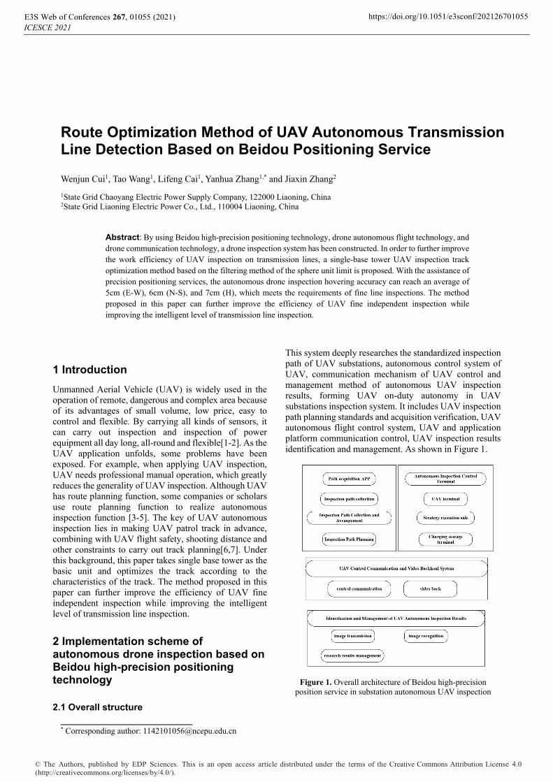
The waypoint during shooting is the track from the first shooting point to the last shooting point. Due to the need to repeatedly adjust the attitude of the drone, the angle of the gimbal, and the action of the camera during the shooting process, there will be a large number of messy shooting point near the shooting point. For this reason, the filtering method of the sphere unit limit is used for preprocessing, as shown in Figure 2.
Take the shooting point as the center and r as the radius to form a spherical unit. Only the shooting waypoint is saved in each unit, and the other shooting point are redundant shooting point. There may be obstacles such as wire and ground between adjacent shooting points. The key inflection point formed by deliberately controlling the drone to avoid obstacles will be obviously different from the cluttered shooting point near the shooting point, which usually appears as the key. The inflection point is far away from the messy shooting point, and the surrounding shooting point are sparse. In order to ensure that the key inflection points between adjacent shooting points are not deleted by mistake, the value of r is not easy to be too
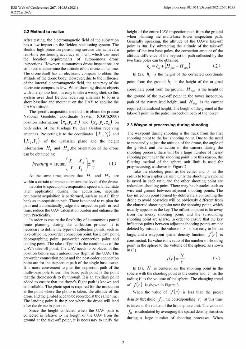
large, and a waypoint spatial density function rf is
constructed. Its value is the ratio of the number of shooting point in the sphere to the volume of the sphere, as shown in (3).
V
Nrf (3)
In (3), N is centered on the shooting point in the sphere with the shooting point as the center and r as the radius;V is the volume of the sphere. The changing trend
of rf is shown in Figure 3.
When the value of rf is less than the preset
density threshold 0f , the corresponding 0r at this time
is taken as the radius of the limit sphere unit. The value of
0f is calculated by averaging the spatial density statistics
during a large number of shooting processes. When
E3S Web of Conferences 267, 01055 (2021)ICESCE 2021
https://doi.org/10.1051/e3sconf/202126701055
2
spheres formed by two adjacent photographing points intersect present, it is retained and the intermediate
photographing point of the track, the other destinations in the sphere are deleted.
Figure 2. Schematic diagram of route points optimization near the shooting point.
Figure 3. Change trends of pace density function of route points near the shooting point.
3 Inspection realization and effect
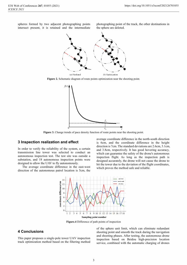
In order to verify the reliability of the system, a certain transmission line tower was selected to conduct an autonomous inspection test. The test site was outside a substation, and 18 autonomous inspection points were designed to allow the UAV to fly autonomously.
The average coordinate difference in the east-west direction of the autonomous patrol location is 5cm, the
average coordinate difference in the north-south direction is 6cm, and the coordinate difference in the height direction is 7cm. The standard deviations are 2.6cm, 3.1cm, and 3.8cm, respectively. It has good hovering accuracy, which can guarantee the safety of the drone's autonomous inspection flight. As long as the inspection path is designed accurately, the drone will not cause the drone to hit the tower due to the deviation of the flight coordinates, which proves the method safe and reliable.
Figure.4 Difference of path points of inspection
4 Conclusions
This paper proposes a single-pole tower UAV inspection track optimization method based on the filtering method
of the sphere unit limit, which can eliminate redundant shooting point and smooth the track during the navigation and shooting phases. After testing, the autonomous drone inspection based on Beidou high-precision location service, combined with the automatic charging of drones
E3S Web of Conferences 267, 01055 (2021)ICESCE 2021
https://doi.org/10.1051/e3sconf/202126701055
3
at the airport and autonomous image recognition, can be used as a daily inspection method for unmanned substations, compared to inspection robots and videos The camera has the advantage of all-round stereo inspection. Not only can it meet the line inspection requirements in terms of shooting effects, but also greatly improve the efficiency of the refined and autonomous inspection of transmission lines, and further enhance the intelligent level of line inspection.
Acknowledgement
This paper was supported by the Science and Technology Project of State Grid Corporation of China under grant 2020YF-61.
References
1. WANG Zhenhua,HUANG Xiaoning,LIANG Kun,et al. Study on the transmission line inspection system based on quadrotor UAVs. J. Electric Power,45(10): 59-62. (2012)
2. LV Ming,SHENG Gehao,ZHANG Weidong,et al. A tower and line tracking algorithm for power transmission line inspection based on unmanned aerial vehicles. J. Automation of Electric Power Systems,36(09): 92-97. (2012)
3. HUANG Shilong,GU Xueping,ZHANG Jiancheng. Design of new oil moving fixed-wing unmanned aerial vehicle for power line patrolling. J. Automation of Electric Power Systems,38(04): 104-108,126. (2014)
4. Yuee Liu,Luis Mejias,Zhengrong Li. Fast power line detection and localization using steerable filter for active UAV guidance. J. XXII Isprs Congress,Technical Commission III, 39(B3): 491-496. (2012)
5. Zhang Kebi,Lei Yong. Design of UAV independent inspection on transmission line based on the camera. J. Measurement Control Technology and Instruments,43(04):83-85,89. (2017)
6. PENG Xiangyang,QIAN Jinju,WU Gongping, et al. Full automatic inspection system and its demonstration application based on robot for overhead transmission lines. J. High Voltage Engineering, 43(8): 2582-2591. (2017)
7. FU Hongan, WANG Xueping, TIAN Shuai, et al. Power transmission line corridor cleaning method based on UAV LiDAR technique. J. Electrical measurement & Instrumentation, 56(23):146-152. (2019)
E3S Web of Conferences 267, 01055 (2021)ICESCE 2021
https://doi.org/10.1051/e3sconf/202126701055
4