UAV PERFORMING AUTONOMOUS LANDING ON …UAV PERFORMING AUTONOMOUS LANDING ON USV UTILIZING THE ROBOT...
6
ASME District F - Early Career Technical Conference Proceedings ASME District F - Early Career Technical Conference, ASME District F – ECTC 2013 November 2 – 3, 2013 - Birmingham, Alabama USA UAV PERFORMING AUTONOMOUS LANDING ON USV UTILIZING THE ROBOT OPERATING SYSTEM Joshua N. Weaver University of Florida Gainesville, Florida, U.S.A. Daniel Z. Frank University of Florida Gainesville, Florida, U.S.A. Dr. Eric M. Schwartz University of Florida Gainesville, Florida, U.S.A. Dr. A. Antonio Arroyo University of Florida Gainesville, Florida, U.S.A. ABSTRACT This paper outlines the design and implementation of the launching and landing of an unmanned aerial vehicle (UAV) onto an unmanned surface vehicle (USV). The US Navy and Northrop Grumman’s X-47B drone have just recently achieved the first autonomous landing of an aircraft onto an aircraft carrier, but it came at the price tag of over one billion U.S. dollars. The authors of this paper will create a scaled-down model of this system that will cost in the order of thousands of dollars. The aerial vehicle utilized in this study is a quadrotor helicopter, which greatly simplifies the launching and landing process. The surface vehicle used is an autonomous boat that features a catamaran-style hull. Both vehicles will use the Robotic Operation System (ROS) as a framework for their software. A successful mission for this system would be one in which the quadrotor launches from the launch pad of the boat, navigates to a series of GPS waypoints, lands at a predetermined location to pick up an object, navigates back to the boat, and then lands successfully to the USV. INTRODUCTION Since World War II, the ability for an aircraft carrier to deploy and recover aerial vehicles thousands of miles from the closest air base has proven to be a great tactical advantage to those forces capable of utilizing them. Despite the advantage that they provide, the success of carriers is largely dependent on the skill and experience of the pilots flying the aircraft. The use of UAVs makes it possible to reduce failure due to human error, while also preventing the loss of human lives in the process. Landing a rotary wing aircraft onto an aircraft carrier has several challenges associated with it. Unlike descent over land, the aircraft pilot has to compensate for the pitching of the ship to make sure the boat doesn’t accidentally slam into the landing gear. This could damage the aircraft as well as cause it to become unstable. As the aircraft approaches the surface of the ship, it becomes susceptible to the ground effect which may also cause it to become difficult to control. A number of researchers have investigated methods to autonomously land UAVs using vision guidance. The simplest method, shown in [1], uses a combination of GPS waypoints and vision to get the UAV in the vicinity of a landing pad. The UAV then uses vision to search for the location of the landing pad. Once the UAV has located the pad using an attached camera, the UAV then begins its descent. In [2,3], more sophisticated methods were developed for UAVs to use vision to identify hazardous features to determine whether or not a surface was safe to land. Also pertinent to this study is the work already done on using UAVs in conjunction with unmanned ground vehicles (UGVs) to accomplish a mission. The research shown in [4] uses a manually flown AUV and an autonomous UGV. The AUV shared the information gathered by its camera to assist the UGV with path planning and obstacle avoidance. A group in Switzerland has also done extensive work in using UAVs magnetically mounted onto the ceiling to help a swarm of UGVs navigate between two targets in a foraging task system that closely mimics ant colony movement [5]. Other focuses of the research show how eye-bots assist foot-bots in traversing a gap clearing environment [6] and using a single eye-bot to assist foot-bots in traveling over a hill in terms of angle steepness and calculating group formation in order to traverse an angle too steep for a single vehicle to climb [7]. Wenzel [8] was able to use vision to autonomously take off and land a quadrotor onto a small ground vehicle with a 90% success rate. However, since their vision system relies on an infrared (IR) camera, their system only works in indoor environments with controlled lighting. Additionally, by landing on a land vehicle in an indoor environment, one can make the assumption that the orientation of the landing surface is constant. Landing on an USV presents an additional challenge, ASME District F - ECTC 2013 Proceedings - Vol. 12 119
-
Upload
nguyencong -
Category
Documents
-
view
242 -
download
5
Transcript of UAV PERFORMING AUTONOMOUS LANDING ON …UAV PERFORMING AUTONOMOUS LANDING ON USV UTILIZING THE ROBOT...
ASME District F - Early Career Technical Conference Proceedings ASME District F - Early Career Technical Conference, ASME District F – ECTC 2013
November 2 – 3, 2013 - Birmingham, Alabama USA
UAV PERFORMING AUTONOMOUS LANDING ON USV UTILIZING THE ROBOT OPERATING SYSTEM
Joshua N. Weaver University of Florida
Gainesville, Florida, U.S.A.
Daniel Z. Frank University of Florida
Gainesville, Florida, U.S.A.
Dr. Eric M. Schwartz University of Florida
Gainesville, Florida, U.S.A.
Dr. A. Antonio Arroyo University of Florida
Gainesville, Florida, U.S.A.
ABSTRACT This paper outlines the design and implementation of the
launching and landing of an unmanned aerial vehicle (UAV) onto an unmanned surface vehicle (USV). The US Navy and Northrop Grumman’s X-47B drone have just recently achieved the first autonomous landing of an aircraft onto an aircraft carrier, but it came at the price tag of over one billion U.S. dollars. The authors of this paper will create a scaled-down model of this system that will cost in the order of thousands of dollars. The aerial vehicle utilized in this study is a quadrotor helicopter, which greatly simplifies the launching and landing process. The surface vehicle used is an autonomous boat that features a catamaran-style hull. Both vehicles will use the Robotic Operation System (ROS) as a framework for their software. A successful mission for this system would be one in which the quadrotor launches from the launch pad of the boat, navigates to a series of GPS waypoints, lands at a predetermined location to pick up an object, navigates back to the boat, and then lands successfully to the USV.
INTRODUCTION Since World War II, the ability for an aircraft carrier to
deploy and recover aerial vehicles thousands of miles from the closest air base has proven to be a great tactical advantage to those forces capable of utilizing them. Despite the advantage that they provide, the success of carriers is largely dependent on the skill and experience of the pilots flying the aircraft. The use of UAVs makes it possible to reduce failure due to human error, while also preventing the loss of human lives in the process.
Landing a rotary wing aircraft onto an aircraft carrier has several challenges associated with it. Unlike descent over land, the aircraft pilot has to compensate for the pitching of the ship to make sure the boat doesn’t accidentally slam into the landing gear. This could damage the aircraft as well as cause it to become unstable. As the aircraft approaches the surface of the
ship, it becomes susceptible to the ground effect which may also cause it to become difficult to control.
A number of researchers have investigated methods to autonomously land UAVs using vision guidance. The simplest method, shown in [1], uses a combination of GPS waypoints and vision to get the UAV in the vicinity of a landing pad. The UAV then uses vision to search for the location of the landing pad. Once the UAV has located the pad using an attached camera, the UAV then begins its descent. In [2,3], more sophisticated methods were developed for UAVs to use vision to identify hazardous features to determine whether or not a surface was safe to land.
Also pertinent to this study is the work already done on using UAVs in conjunction with unmanned ground vehicles (UGVs) to accomplish a mission. The research shown in [4] uses a manually flown AUV and an autonomous UGV. The AUV shared the information gathered by its camera to assist the UGV with path planning and obstacle avoidance. A group in Switzerland has also done extensive work in using UAVs magnetically mounted onto the ceiling to help a swarm of UGVs navigate between two targets in a foraging task system that closely mimics ant colony movement [5]. Other focuses of the research show how eye-bots assist foot-bots in traversing a gap clearing environment [6] and using a single eye-bot to assist foot-bots in traveling over a hill in terms of angle steepness and calculating group formation in order to traverse an angle too steep for a single vehicle to climb [7].
Wenzel [8] was able to use vision to autonomously take off and land a quadrotor onto a small ground vehicle with a 90% success rate. However, since their vision system relies on an infrared (IR) camera, their system only works in indoor environments with controlled lighting. Additionally, by landing on a land vehicle in an indoor environment, one can make the assumption that the orientation of the landing surface is constant. Landing on an USV presents an additional challenge,
ASME District F - ECTC 2013 Proceedings - Vol. 12 119
since the orientation of the vehicle’s landing surface is also free to roll and pitch.
In this paper, the design and implementation of a heterogeneous robotic system composed of a UAV and an USV will be detailed. ROS is used to handle high-level behaviors, perform controls, and facilitate communications between the USV and UAV. Using vision, the UAV will be able to safely land on both a stationary target as well as a landing pad mounted on top of the USV in both indoor and outdoor lighting conditions.
UNMANNED SURFACE VEHICLE DESIGN The unmanned surface vehicle used in this study was
designed and built by undergraduate and graduate students at the Machine Intelligence Laboratory (MIL) at the University of Florida. It was initially designed for the purpose of competing in the Association for Unmanned Vehicles Systems (AUVSI) and Office of Naval Research’s (ONR) 6th Annual International RoboBoat Competition. The USV earned first place and has since been devoted to robotics research.
Figure 1. CAD rendering of the USV and UAV system
The USV used in this study features a catamaran-style hull to provide stability as well as a shallow draft. The two pontoons are held together with a frame composed of 8020 aluminum extrusions. For propulsion, the USV has four trolling motors. The front pair is pointed inwards at an angle of 30° while the back pair is pointed 30° outwards. This allows the USV to translate in any direction as well as rotate in place. Combined, the four trolling motors are capable of providing up to 22 lbs of forward thrust. It has a water displacement of 115 lbs and overall dimensions of 72” x 30” x 36” (length x width x height) [9].
A complete computer-aided design (CAD) model of the USV and UAV system was created using SolidWorks and can be seen in Figure 1. There are several benefits to creating a CAD model for a vehicle. First, the model allows the designer to visualize how components fit together. Second, it facilitates the use of engineering analysis tools. For example, airflow simulations conducted on the model helped determine the
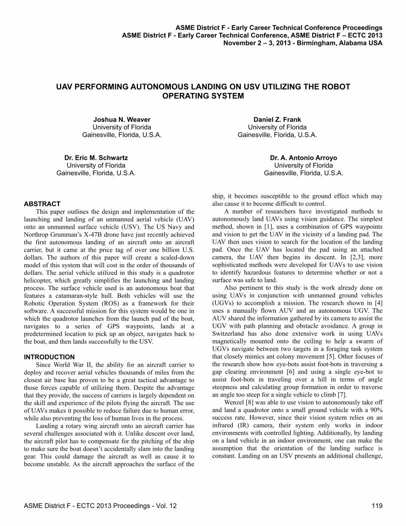
geometry of the vents used for the USV’s cooling system. Third, the individual components that make up the model can easily be fabricated using the lab’s Dimension SST 1200es 3D printer or Roland MDX-540 SRP 3D milling machine as shown in Figure 2.
Figure 2. Fabricating parts using the 3D milling machine
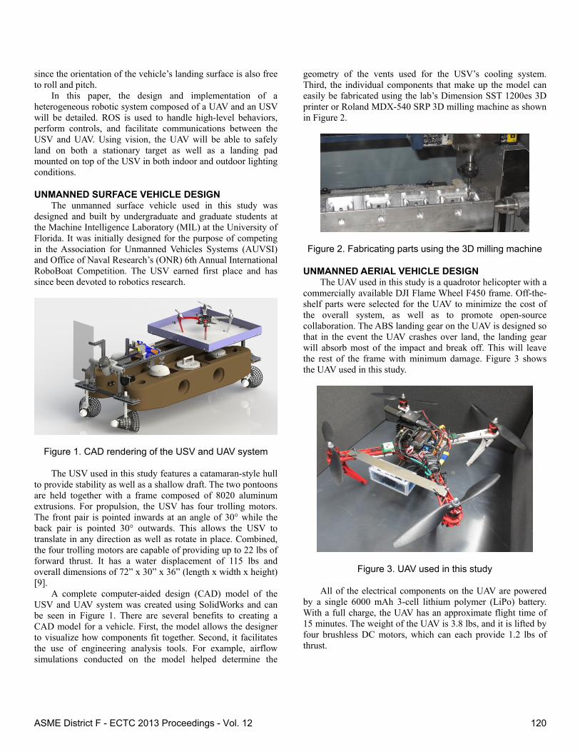
UNMANNED AERIAL VEHICLE DESIGN The UAV used in this study is a quadrotor helicopter with a
commercially available DJI Flame Wheel F450 frame. Off-the-shelf parts were selected for the UAV to minimize the cost of the overall system, as well as to promote open-source collaboration. The ABS landing gear on the UAV is designed so that in the event the UAV crashes over land, the landing gear will absorb most of the impact and break off. This will leave the rest of the frame with minimum damage. Figure 3 shows the UAV used in this study.
Figure 3. UAV used in this study
All of the electrical components on the UAV are powered by a single 6000 mAh 3-cell lithium polymer (LiPo) battery. With a full charge, the UAV has an approximate flight time of 15 minutes. The weight of the UAV is 3.8 lbs, and it is lifted by four brushless DC motors, which can each provide 1.2 lbs of thrust.
ASME District F - ECTC 2013 Proceedings - Vol. 12 120
Basic stabilization and navigation is handled with an ArduPilot Mega (APM) 2.5+ autopilot control board. Control and sensor processing abilities are provided to the UAV via a quad-core ARM ODROID-U2 installed with Linux-Ubuntu and ROS. The ODROID can retrieve information such as current orientation and GPS location from the APM. The ODROID is also capable of sending the APM information such as a desired attitude or GPS waypoint. The main sensor of the UAV is a Logitech HD Pro Webcam C920 camera which is used for computer vision as well as obstacle and target identification. Communication between the two vehicles is handled by XBee RF devices which have a range of approximately of 300 feet.
ROS ENVIRONMENT Both the USV and the UAV operate within a ROS
environment. ROS was chosen due to the open source nature of the software. This allows for various sources of code to be used or for code developed in this research to be easily shared. ROS also allows an easy method for all code, in the form of nodes, to be duplicated and moved to multiple vehicles. This is used throughout the various levels in the heterogeneous cooperative system. Some of the groundwork code for the UAV was completed in previous studies [10,11].
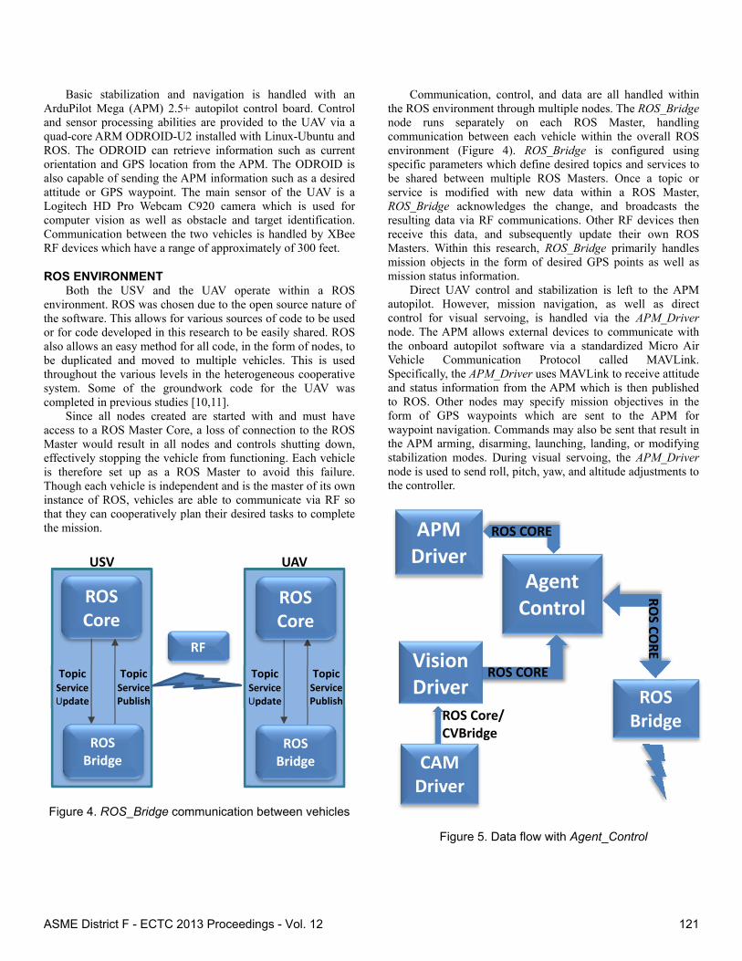
Since all nodes created are started with and must have access to a ROS Master Core, a loss of connection to the ROS Master would result in all nodes and controls shutting down, effectively stopping the vehicle from functioning. Each vehicle is therefore set up as a ROS Master to avoid this failure. Though each vehicle is independent and is the master of its own instance of ROS, vehicles are able to communicate via RF so that they can cooperatively plan their desired tasks to complete the mission.
Figure 4. ROS_Bridge communication between vehicles
Communication, control, and data are all handled within the ROS environment through multiple nodes. The ROS_Bridge node runs separately on each ROS Master, handling communication between each vehicle within the overall ROS environment (Figure 4). ROS_Bridge is configured using specific parameters which define desired topics and services to be shared between multiple ROS Masters. Once a topic or service is modified with new data within a ROS Master, ROS_Bridge acknowledges the change, and broadcasts the resulting data via RF communications. Other RF devices then receive this data, and subsequently update their own ROS Masters. Within this research, ROS_Bridge primarily handles mission objects in the form of desired GPS points as well as mission status information.
Direct UAV control and stabilization is left to the APM autopilot. However, mission navigation, as well as direct control for visual servoing, is handled via the APM_Driver node. The APM allows external devices to communicate with the onboard autopilot software via a standardized Micro Air Vehicle Communication Protocol called MAVLink. Specifically, the APM_Driver uses MAVLink to receive attitude and status information from the APM which is then published to ROS. Other nodes may specify mission objectives in the form of GPS waypoints which are sent to the APM for waypoint navigation. Commands may also be sent that result in the APM arming, disarming, launching, landing, or modifying stabilization modes. During visual servoing, the APM_Driver node is used to send roll, pitch, yaw, and altitude adjustments to the controller.
Figure 5. Data flow with Agent_Control
ROS Core
ROS Bridge
Topic Service Update
RF
USV
Topic Service Publish
Topic Service Update
UAV
TopicService Publish
ROS Core
ROS Bridge
Agent Control
ROS Bridge ROS Core/
CVBridge
APM Driver
CAM Driver
Vision Driver
ROS CORE
ROS CORE
ROS CO
RE
ASME District F - ECTC 2013 Proceedings - Vol. 12 121
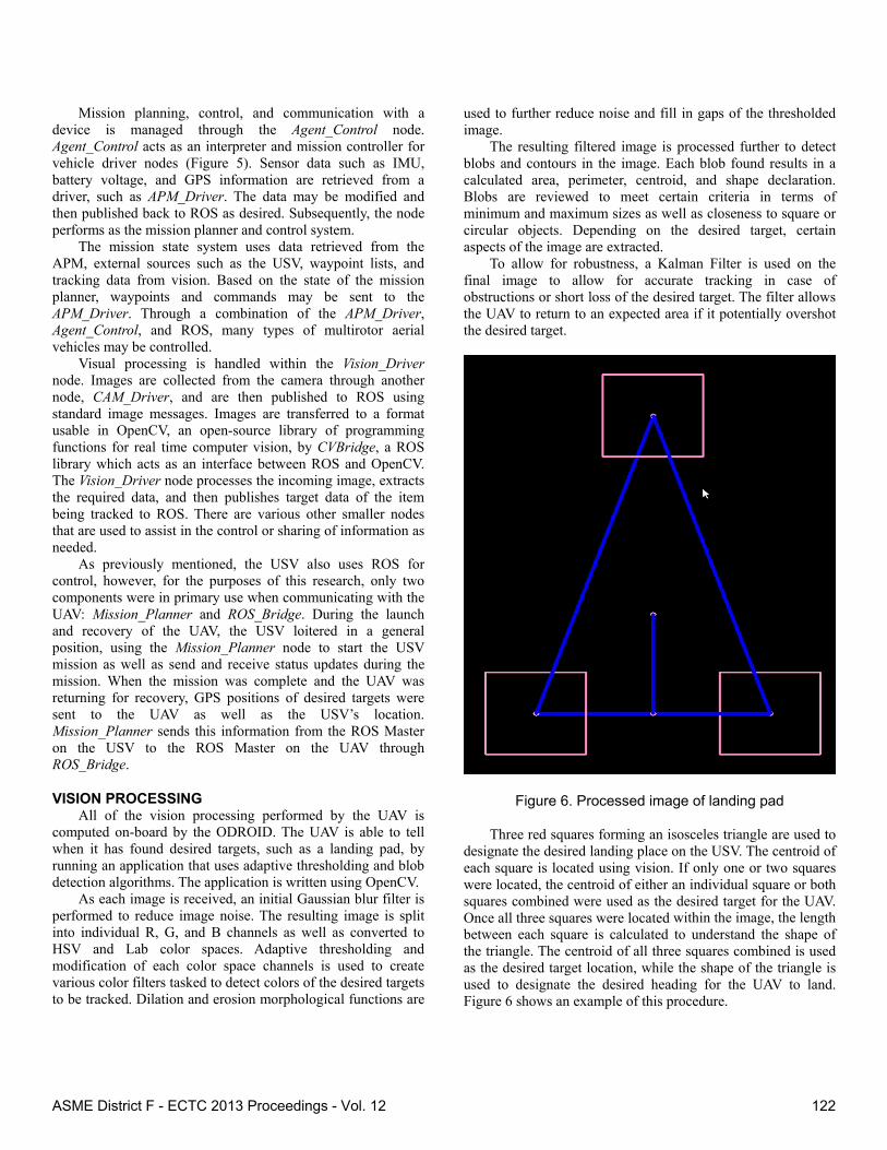
Mission planning, control, and communication with a device is managed through the Agent_Control node. Agent_Control acts as an interpreter and mission controller for vehicle driver nodes (Figure 5). Sensor data such as IMU, battery voltage, and GPS information are retrieved from a driver, such as APM_Driver. The data may be modified and then published back to ROS as desired. Subsequently, the node performs as the mission planner and control system.
The mission state system uses data retrieved from the APM, external sources such as the USV, waypoint lists, and tracking data from vision. Based on the state of the mission planner, waypoints and commands may be sent to the APM_Driver. Through a combination of the APM_Driver, Agent_Control, and ROS, many types of multirotor aerial vehicles may be controlled.
Visual processing is handled within the Vision_Driver node. Images are collected from the camera through another node, CAM_Driver, and are then published to ROS using standard image messages. Images are transferred to a format usable in OpenCV, an open-source library of programming functions for real time computer vision, by CVBridge, a ROS library which acts as an interface between ROS and OpenCV. The Vision_Driver node processes the incoming image, extracts the required data, and then publishes target data of the item being tracked to ROS. There are various other smaller nodes that are used to assist in the control or sharing of information as needed.
As previously mentioned, the USV also uses ROS for control, however, for the purposes of this research, only two components were in primary use when communicating with the UAV: Mission_Planner and ROS_Bridge. During the launch and recovery of the UAV, the USV loitered in a general position, using the Mission_Planner node to start the USV mission as well as send and receive status updates during the mission. When the mission was complete and the UAV was returning for recovery, GPS positions of desired targets were sent to the UAV as well as the USV’s location. Mission_Planner sends this information from the ROS Master on the USV to the ROS Master on the UAV through ROS_Bridge.
VISION PROCESSING All of the vision processing performed by the UAV is
computed on-board by the ODROID. The UAV is able to tell when it has found desired targets, such as a landing pad, by running an application that uses adaptive thresholding and blob detection algorithms. The application is written using OpenCV.
As each image is received, an initial Gaussian blur filter is performed to reduce image noise. The resulting image is split into individual R, G, and B channels as well as converted to HSV and Lab color spaces. Adaptive thresholding and modification of each color space channels is used to create various color filters tasked to detect colors of the desired targets to be tracked. Dilation and erosion morphological functions are
used to further reduce noise and fill in gaps of the thresholded image.
The resulting filtered image is processed further to detect blobs and contours in the image. Each blob found results in a calculated area, perimeter, centroid, and shape declaration. Blobs are reviewed to meet certain criteria in terms of minimum and maximum sizes as well as closeness to square or circular objects. Depending on the desired target, certain aspects of the image are extracted.
To allow for robustness, a Kalman Filter is used on the final image to allow for accurate tracking in case of obstructions or short loss of the desired target. The filter allows the UAV to return to an expected area if it potentially overshot the desired target.
Figure 6. Processed image of landing pad
Three red squares forming an isosceles triangle are used to designate the desired landing place on the USV. The centroid of each square is located using vision. If only one or two squares were located, the centroid of either an individual square or both squares combined were used as the desired target for the UAV. Once all three squares were located within the image, the length between each square is calculated to understand the shape of the triangle. The centroid of all three squares combined is used as the desired target location, while the shape of the triangle is used to designate the desired heading for the UAV to land. Figure 6 shows an example of this procedure.
ASME District F - ECTC 2013 Proceedings - Vol. 12 122
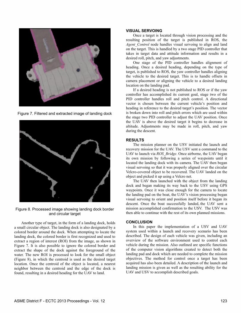
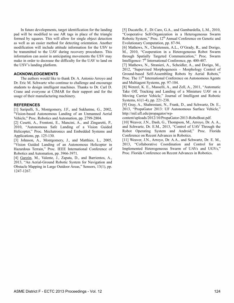
Figure 7. Filtered and extracted image of landing dock
Figure 8. Processed image showing landing dock border and circular target
Another type of target, in the form of a landing dock, holds
a small circular object. The landing dock is also designated by a colored border around the dock. When attempting to locate the landing dock, the colored border is first recognized and used to extract a region of interest (ROI) from the image, as shown in Figure 7. It is also possible to ignore the colored border and extract the shape of the dock against the foreground of the water. The new ROI is processed to look for the small object (Figure 8), in which the centroid is used as the desired target location. Once the centroid of the object is located, a nearest neighbor between the centroid and the edge of the dock is found, resulting in a desired heading for the UAV to land.
VISUAL SERVOING Once a target is located through vision processing and the
resulting position of the target is published in ROS, the Agent_Control node handles visual servoing to align and land on the target. This is handled by a two stage PID controller that takes in target data and attitude information and results in a desired roll, pitch, and yaw adjustments.
One stage of the PID controller handles alignment of heading. Once a desired heading, depending on the type of target, is published to ROS, the yaw controller handles aligning the vehicle to the desired target. This is to handle offsets in camera placement or aligning the vehicle to a desired landing location on the landing pad.
If a desired heading is not published to ROS or if the yaw controller has accomplished its current goal, stage two of the PID controller handles roll and pitch control. A directional vector is chosen between the current vehicle’s position and heading in reference to the desired target’s position. The vector is broken down into roll and pitch errors which are used within the stage two PID controller to adjust the UAV position. Once the UAV is above the desired target it begins to decrease in altitude. Adjustments may be made in roll, pitch, and yaw during the descent.
RESULTS The mission planner on the USV initiated the launch and
recovery mission for the UAV. The USV sent a command to the UAV to launch via ROS_Bridge. Once airborne, the UAV began its own mission by following a series of waypoints until it located the landing dock with its camera. The UAV then began visual servoing so that it was properly aligned over the circular Velcro-covered object to be recovered. The UAV landed on the object and picked it up using a Velcro net.
The UAV then launched with the object from the landing dock and began making its way back to the USV using GPS waypoints. Once it was close enough for the camera to locate the landing pad on the boat, the UAV’s vision processing began visual servoing to orient and position itself before it began its descent. Once the boat successfully landed, the UAV sent a mission accomplished confirmation to the USV. The USV was then able to continue with the rest of its own planned missions.
CONCLUSION In this paper the implementation of a USV and UAV
system used within a launch and recovery scenario has been described. The design of each vehicle was given, including an overview of the software environment used to control each vehicle during the mission. Also outlined are specific functions of the computer vision algorithms created to detect both the landing pad and dock which are needed to complete the mission objectives. The method for control once a target has been acquired has also been detailed. A description of the launch and landing mission is given as well as the resulting ability for the UAV and USV to accomplish described goals.
ASME District F - ECTC 2013 Proceedings - Vol. 12 123
In future developments, target identification for the landing pad will be modified to use AR tags in place of the triangle formed by squares. This will allow for single object detection as well as an easier method for detecting orientation. Another modification will include attitude information for the USV to be transmitted to the UAV during recovery procedures. This information can assist in anticipating movements the USV may make in order to decrease the difficulty for the UAV to land on the USV’s landing platform.
ACKNOWLEDGEMENTS The authors would like to thank Dr. A. Antonio Arroyo and
Dr. Eric M. Schwartz who continue to challenge and encourage students to design intelligent machines. Thanks to Dr. Carl D. Crane and everyone at CIMAR for their support and for the usage of their manufacturing machinery.
REFERENCES [1] Saripalli, S., Montgomery, J.F., and Sukhatme, G., 2002, "Vision-based Autonomous Landing of an Unmanned Aerial Vehicle," Proc. Robotics and Automation, pp. 2799-2804. [2] Cesetti, A., Frontoni, E., Mancini, A., and Zingaretti, P., 2010, “Autonomous Safe Landing of a Vision Guided Helicopter,” Proc. Mechatronics and Embedded Systems and Applications, pp. 125-130. [3] Johnson, A., Montgomery, J., and Matthies, L., 2005, “Vision Guided Landing of an Autonomous Helicopter in Hazardous Terrain,” Proc. IEEE International Conference of Robotics and Automation, pp. 3966-3971. [4] Garzón, M., Valente, J., Zapata, D., and Barrientos, A., 2013, “An Aerial-Ground Robotic System for Navigation and Obstacle Mapping in Large Outdoor Areas,” Sensors, 13(1), pp. 1247-1267.
[5] Ducatelle, F., Di Caro, G.A., and Gambardella, L.M., 2010, “Cooperative Self-Organization in a Heterogeneous Swarm Robotic System,” Proc. 12th Annual Conference on Genetic and Evolutionary Computation, pp. 87-94. [6] Mathews, N., Christensen, A.L., O’Grady, R., and Dorigo, M., 2010, “Cooperation in a Heterogeneous Robot Swarm through Spatially Targeted Communication,” Proc. Swarm Intelligence: 7th International Conference, pp. 400-407. [7] Mathews, N., Stranieri, A., Scheidler, A., and Dorigo, M., 2012, “Supervised Morphogenesis – Morphology Control of Ground-based Self-Assembling Robots by Aerial Robots,” Proc. The 11th International Conference on Autonomous Agents and Multiagent Systems, pp. 97-104. [8] Wenzel, K. E., Masselli, A., and Zell, A., 2011, “Automatic Take Off, Tracking and Landing of a Miniature UAV on a Moving Carrier Vehicle,” Journal of Intelligent and Robotic Systems, 61(1-4), pp. 221-238. [9] Gray, A., Shahrestani, N., Frank, D., and Schwartz, Dr. E., 2013, “PropaGator 2013: UF Autonomous Surface Vehicle,” http://mil.ufl.edu/propagator/wp-content/uploads/2012/10/PropaGator-2013-RoboBoat.pdf. [10] Weaver, J.N., Dash, G., Thompson, M., Arroyo, Dr. A. A., and Schwartz, Dr. E.M., 2013, “Control of UAV Through the Robot Operating System and Android,” Proc. Florida Conference on Recent Advances in Robotics. [11] Weaver, J.N., Arroyo, Dr. A.A., and Schwartz, Dr. E. M., 2013, “Collaborative Coordination and Control for an Implemented Heterogeneous Swarm of UAVs and UGVs,” Proc. Florida Conference on Recent Advances in Robotics.
ASME District F - ECTC 2013 Proceedings - Vol. 12 124