Rotodynamic Pumps
21
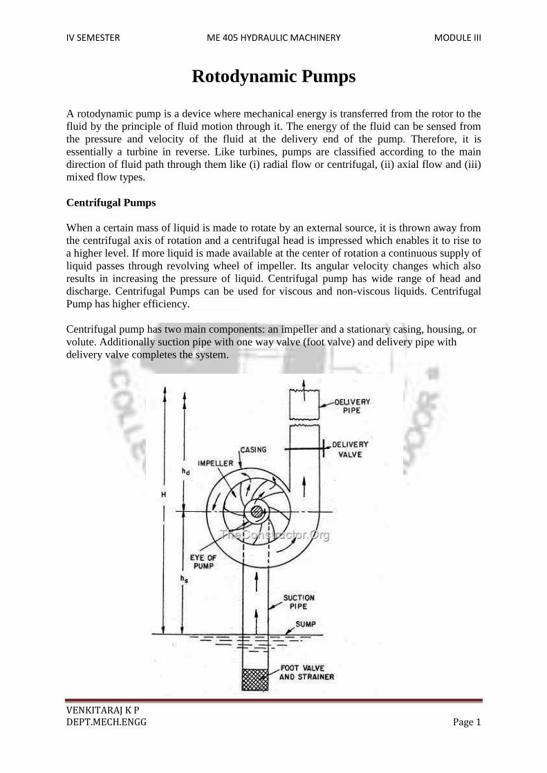
IV SEMESTER ME 405 HYDRAULIC MACHINERY MODULE III VENKITARAJ K P DEPT.MECH.ENGG Page 1 Rotodynamic Pumps A rotodynamic pump is a device where mechanical energy is transferred from the rotor to the fluid by the principle of fluid motion through it. The energy of the fluid can be sensed from the pressure and velocity of the fluid at the delivery end of the pump. Therefore, it is essentially a turbine in reverse. Like turbines, pumps are classified according to the main direction of fluid path through them like (i) radial flow or centrifugal, (ii) axial flow and (iii) mixed flow types. Centrifugal Pumps When a certain mass of liquid is made to rotate by an external source, it is thrown away from the centrifugal axis of rotation and a centrifugal head is impressed which enables it to rise to a higher level. If more liquid is made available at the center of rotation a continuous supply of liquid passes through revolving wheel of impeller. Its angular velocity changes which also results in increasing the pressure of liquid. Centrifugal pump has wide range of head and discharge. Centrifugal Pumps can be used for viscous and non-viscous liquids. Centrifugal Pump has higher efficiency. Centrifugal pump has two main components: an impeller and a stationary casing, housing, or volute. Additionally suction pipe with one way valve (foot valve) and delivery pipe with delivery valve completes the system.
-
Upload
aleksandar -
Category
Documents
-
view
53 -
download
1
description
Rotodynamic Pumps
Transcript of Rotodynamic Pumps
IV SEMESTER ME 405 HYDRAULIC MACHINERY MODULE III
VENKITARAJ K P
DEPT.MECH.ENGG Page 1
Rotodynamic Pumps
A rotodynamic pump is a device where mechanical energy is transferred from the rotor to the fluid by the principle of fluid motion through it. The energy of the fluid can be sensed from the pressure and velocity of the fluid at the delivery end of the pump. Therefore, it is essentially a turbine in reverse. Like turbines, pumps are classified according to the main direction of fluid path through them like (i) radial flow or centrifugal, (ii) axial flow and (iii) mixed flow types. Centrifugal Pumps When a certain mass of liquid is made to rotate by an external source, it is thrown away from the centrifugal axis of rotation and a centrifugal head is impressed which enables it to rise to a higher level. If more liquid is made available at the center of rotation a continuous supply of liquid passes through revolving wheel of impeller. Its angular velocity changes which also results in increasing the pressure of liquid. Centrifugal pump has wide range of head and discharge. Centrifugal Pumps can be used for viscous and non-viscous liquids. Centrifugal Pump has higher efficiency. Centrifugal pump has two main components: an impeller and a stationary casing, housing, or volute. Additionally suction pipe with one way valve (foot valve) and delivery pipe with delivery valve completes the system.

IV SEMESTER ME 405 HYDRAULIC MACHINERY MODULE III
VENKITARAJ K P
DEPT.MECH.ENGG Page 2
1. IMPELLER An impeller attached to the rotating shaft. The impeller consists of a number of blades, also sometimes called vanes, arranged in a regular pattern around the shaft. The impeller may be classified as open impeller and enclosed or shrouded impeller. A simple disc with blades mounted perpendicularly on it is called open impeller. If another disc is used to cover the blades, this type is called shrouded impeller. This is more popular with water pumps. Open impellers are well adopted for use with dirty or water containing solids. The third type is just the blades spreading out from the shaft. These are used to pump slurries. Impellers may be of cast iron or bronzes or steel or special alloys as required by the application. In order to maintain constant radial velocity, the width of the impeller will be wider at entrance and narrower at the exit. The blades are generally cast integral with the disc. Recently even plastic material is used.
(a) Open impeller, (b) enclosed or shrouded impeller
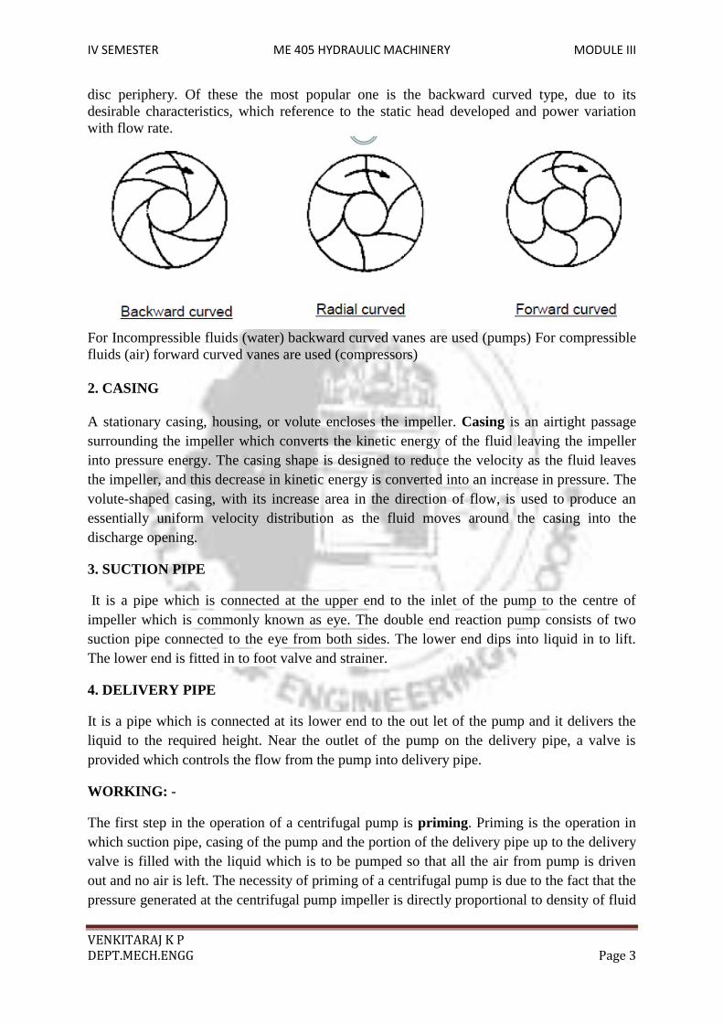
The blades may of three different orientations. These are (i) Radial, (ii) Backward curved, and (iii) Forward curved. Backward and forward refers to the direction of motion of the
IV SEMESTER ME 405 HYDRAULIC MACHINERY MODULE III
VENKITARAJ K P
DEPT.MECH.ENGG Page 3
disc periphery. Of these the most popular one is the backward curved type, due to its desirable characteristics, which reference to the static head developed and power variation with flow rate.
For Incompressible fluids (water) backward curved vanes are used (pumps) For compressible fluids (air) forward curved vanes are used (compressors) 2. CASING A stationary casing, housing, or volute encloses the impeller. Casing is an airtight passage surrounding the impeller which converts the kinetic energy of the fluid leaving the impeller into pressure energy. The casing shape is designed to reduce the velocity as the fluid leaves the impeller, and this decrease in kinetic energy is converted into an increase in pressure. The volute-shaped casing, with its increase area in the direction of flow, is used to produce an essentially uniform velocity distribution as the fluid moves around the casing into the discharge opening.
3. SUCTION PIPE
It is a pipe which is connected at the upper end to the inlet of the pump to the centre of impeller which is commonly known as eye. The double end reaction pump consists of two suction pipe connected to the eye from both sides. The lower end dips into liquid in to lift. The lower end is fitted in to foot valve and strainer.
4. DELIVERY PIPE
It is a pipe which is connected at its lower end to the out let of the pump and it delivers the liquid to the required height. Near the outlet of the pump on the delivery pipe, a valve is provided which controls the flow from the pump into delivery pipe.
WORKING: -
The first step in the operation of a centrifugal pump is priming. Priming is the operation in which suction pipe, casing of the pump and the portion of the delivery pipe up to the delivery valve is filled with the liquid which is to be pumped so that all the air from pump is driven out and no air is left. The necessity of priming of a centrifugal pump is due to the fact that the pressure generated at the centrifugal pump impeller is directly proportional to density of fluid
IV SEMESTER ME 405 HYDRAULIC MACHINERY MODULE III
VENKITARAJ K P
DEPT.MECH.ENGG Page 4
that is in contact with it. The one way foot value keeps the suction line and the pump casing filled with water.
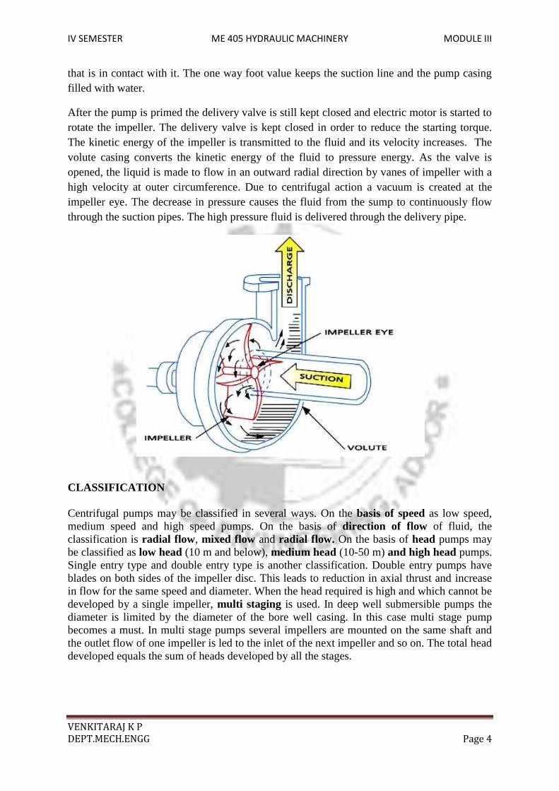
After the pump is primed the delivery valve is still kept closed and electric motor is started to rotate the impeller. The delivery valve is kept closed in order to reduce the starting torque. The kinetic energy of the impeller is transmitted to the fluid and its velocity increases. The volute casing converts the kinetic energy of the fluid to pressure energy. As the valve is opened, the liquid is made to flow in an outward radial direction by vanes of impeller with a high velocity at outer circumference. Due to centrifugal action a vacuum is created at the impeller eye. The decrease in pressure causes the fluid from the sump to continuously flow through the suction pipes. The high pressure fluid is delivered through the delivery pipe.
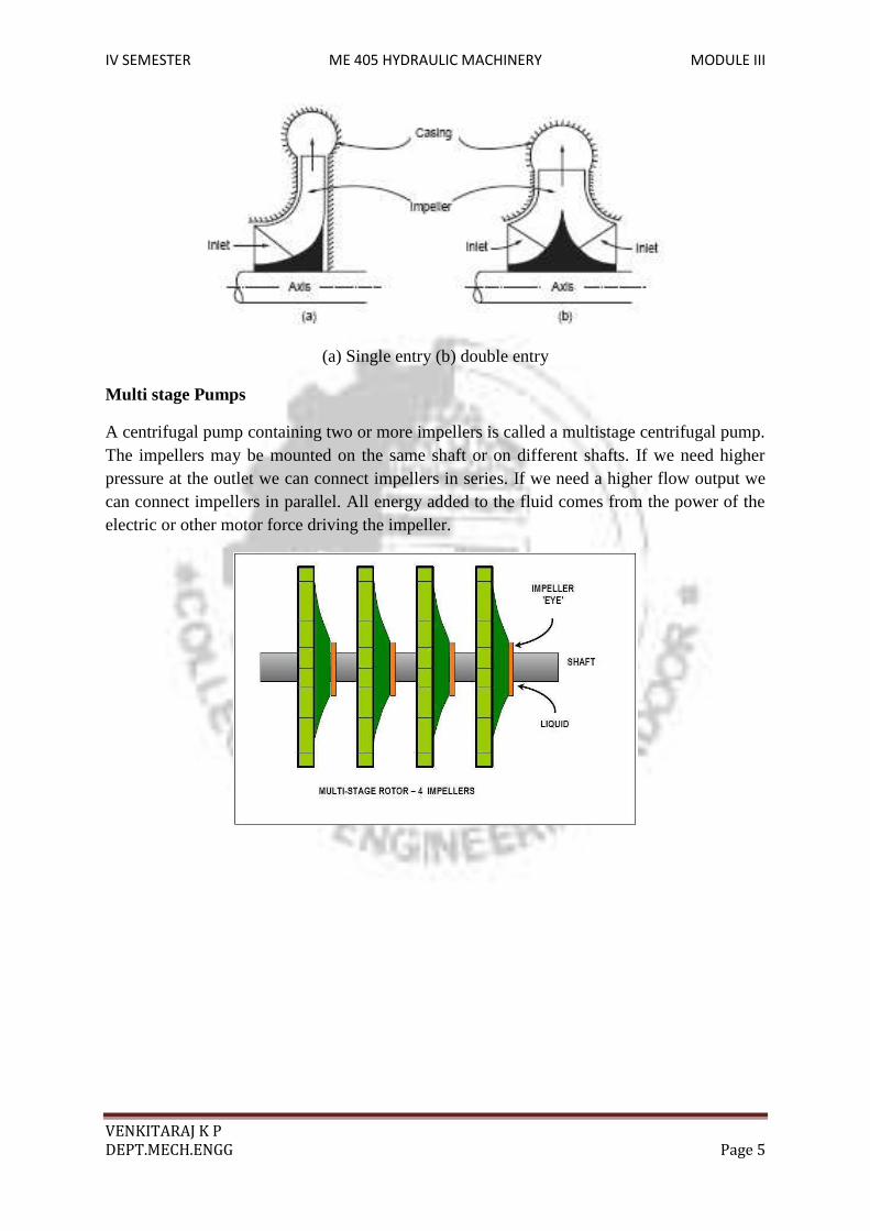
CLASSIFICATION Centrifugal pumps may be classified in several ways. On the basis of speed as low speed, medium speed and high speed pumps. On the basis of direction of flow of fluid, the classification is radial flow, mixed flow and radial flow. On the basis of head pumps may be classified as low head (10 m and below), medium head (10-50 m) and high head pumps. Single entry type and double entry type is another classification. Double entry pumps have blades on both sides of the impeller disc. This leads to reduction in axial thrust and increase in flow for the same speed and diameter. When the head required is high and which cannot be developed by a single impeller, multi staging is used. In deep well submersible pumps the diameter is limited by the diameter of the bore well casing. In this case multi stage pump becomes a must. In multi stage pumps several impellers are mounted on the same shaft and the outlet flow of one impeller is led to the inlet of the next impeller and so on. The total head developed equals the sum of heads developed by all the stages.
IV SEMESTER ME 405 HYDRAULIC MACHINERY MODULE III
VENKITARAJ K P
DEPT.MECH.ENGG Page 5
(a) Single entry (b) double entry
Multi stage Pumps
A centrifugal pump containing two or more impellers is called a multistage centrifugal pump. The impellers may be mounted on the same shaft or on different shafts. If we need higher pressure at the outlet we can connect impellers in series. If we need a higher flow output we can connect impellers in parallel. All energy added to the fluid comes from the power of the electric or other motor force driving the impeller.

IV SEMESTER ME 405 HYDRAULIC MACHINERY MODULE III
VENKITARAJ K P
DEPT.MECH.ENGG Page 6
WORK DONE BY THE IMPELLER
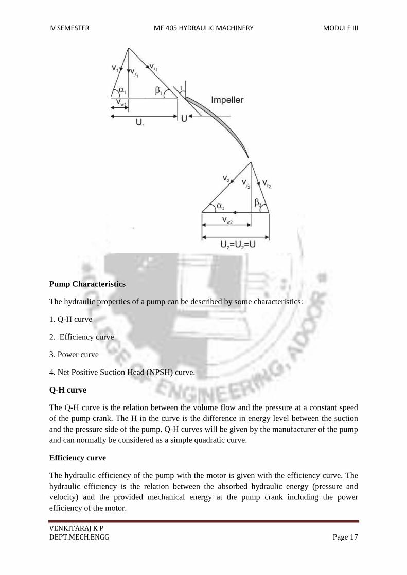
The liquid enters the impeller at its centre and leaves at its outer periphery. The velocity diagrams at the inlet and exit of a backward curved vane is shown in the figure given below.
, – , – , – , – ,

IV SEMESTER ME 405 HYDRAULIC MACHINERY MODULE III
VENKITARAJ K P
DEPT.MECH.ENGG Page 7
-Vane angle at inlet, - vane angle at exit
For best efficiency of the pump it is commonly assumed that the liquid enters the impeller radially so that the absolute velocity vector at the inlet to the impeller is in radial direction. Therefore the velocity of whirl at inlet is zero. So the inlet triangle is right angled. Further it is assumed that the liquid enters and leaves the impeller without shock. This is ensured with the relative velocities at inlet and exit tangential to the vane.
The Euler’s equation for a turbomachinery is given as,
where W is the weight of the liquid striking the impeller per second.
The above equation can be transformed into the following form
+
The work done on the liquid consists of three parts. The first part represents the change in kinetic energy. of the liquid, the second part represents the effect of centrifugal head and the last part indicates the change in static pressure energy of the liquid. This equation is known as the fundamental equation of centrifugal pump.
Since the whirl velocity,
Work done per unit weight of the liquid = HEAD DEVELOPED BY THE IMPELLER
The general arrangement of a centrifugal pump system is shown below

IV SEMESTER ME 405 HYDRAULIC MACHINERY MODULE III
VENKITARAJ K P
DEPT.MECH.ENGG Page 8
The head of a centrifugal pump may be expressed in the following two ways
( i) Static head
(ii) Manometric head
Static Head
The static head is the vertical distance between the liquid surfaces in the sump and the tank to which the liquid is delivered by the pump.
Static head,
Hs = hs +hd
Manometric Head
It is the total head that must be developed by the pump inorder to satisfy the external requirements. The manometric head is equal to the energy given to the liquid by the impeller. Considering the losses in the pump, it is given as
Applying Bernoulli’s theorem between the water surface in the sump and pump suction ( point 0 & 1)

IV SEMESTER ME 405 HYDRAULIC MACHINERY MODULE III
VENKITARAJ K P
DEPT.MECH.ENGG Page 9
or Where is the pressure at the eye of the impeller (suction point) and is the velocity in
the suction pipe, and are the suction lift and friction head loss in the suction pipe
respectively. Applying Bernoulli’s theorem between pump delivery and the delivery point in the tank (point 2 & 3)
Or Where the pressure at the pump delivery is point and is the velocity in the suction pipe, and are the delivery lift and friction head loss in the delivery pipe respectively. Pressure head developed by the impeller or the manometric head is given by ( Assuming that the suction and delivery gauges are at the same level.
thus, manometric head is given as Where is the static head is the total friction head loss in the suction and delivery side , is the velocity head in the suction pipe.
LOSSES IN THE CENTRIFUGAL PUMP
The various losses occurring during the operation of a centrifugal pump are

IV SEMESTER ME 405 HYDRAULIC MACHINERY MODULE III
VENKITARAJ K P
DEPT.MECH.ENGG Page 10
i) Hydraulic losses: Shock or eddy losses at the entrance to and exit from the impeller, Friction Losses in the impeller, Friction and eddy losses in the guide vanes ( or diffuser) and casing.
ii) Mechanical losses: Disc friction between the impeller and the liquid which fills the clearance between the impeller and the casing, Mechanical friction of the main bearings and glands.
iii) Leakage losses: The liquid which escapes or leaks from a high pressure zone to a low pressure zone carries with it energy which is subsequently wasted in eddies.
EFFICIENCIES OF A CENTRIFUGAL PUMP
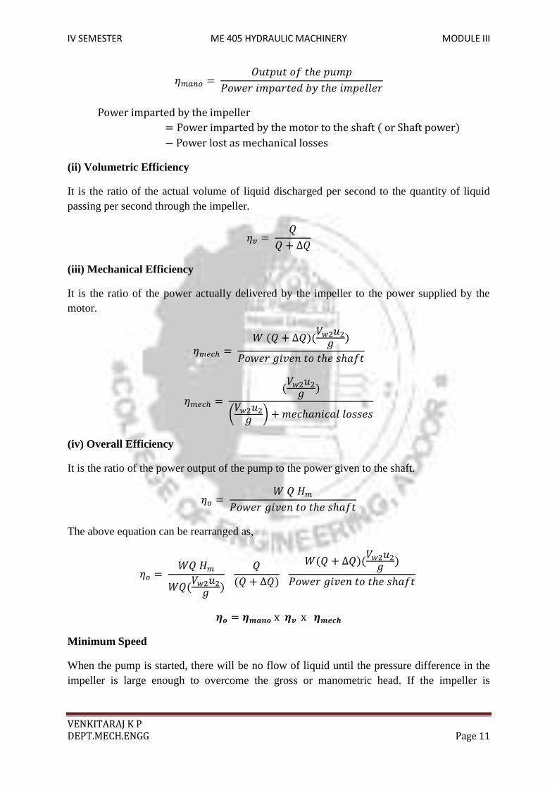
(i) Manometric Efficiency
It is the ratio of manometric head developed by the pump to the head imparted by the impeller to the liquid.
If Q is the actual discharge of the pump, and W is the weight of the liquid discharged per second, then
or
IV SEMESTER ME 405 HYDRAULIC MACHINERY MODULE III
VENKITARAJ K P
DEPT.MECH.ENGG Page 11
(ii) Volumetric Efficiency
It is the ratio of the actual volume of liquid discharged per second to the quantity of liquid passing per second through the impeller.
(iii) Mechanical Efficiency
It is the ratio of the power actually delivered by the impeller to the power supplied by the motor.
(iv) Overall Efficiency
It is the ratio of the power output of the pump to the power given to the shaft.
The above equation can be rearranged as,
Minimum Speed
When the pump is started, there will be no flow of liquid until the pressure difference in the impeller is large enough to overcome the gross or manometric head. If the impeller is

IV SEMESTER ME 405 HYDRAULIC MACHINERY MODULE III
VENKITARAJ K P
DEPT.MECH.ENGG Page 12
rotating, but there is no flow, the liquid is rotating in a forced vortex. Therefore a centrifugal head or pressure head caused by the liquid is given as
The flow will start if
Since , the minimum speed of the centrifugal pump can be obtained from the above
condition.
Specific Speed
In order to compare the performance of different pumps, the term ‘specific speed’ is commonly used. This is a type characteristic, and can be used to predict the behaviour of one pump based on the tests on similar, but different sized pumps.
The specific speed of a centrifugal pump may be defined as the speed in revolutions per minute of a geometrically similar pump of such a size that under corresponding conditions it would deliver 1 litre of liquid per second against a head of 1 metre. It is represented by Ns
Discharge Q of the pump may be written as , where & are the diameter and width of the impeller at the exit
But , where ψ is the flow ratio.
Therefore
or -----------------------------------I we have
IV SEMESTER ME 405 HYDRAULIC MACHINERY MODULE III
VENKITARAJ K P
DEPT.MECH.ENGG Page 13
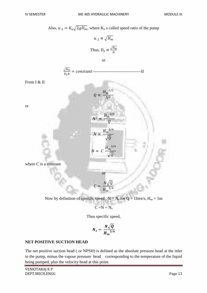
Also, , where Ku s called speed ratio of the pump
Thus,
or
-----------------------------------II From I & II
or
where C is a constant
or
Now by definition of specific speed , N = Ns for Q = 1litre/s, Hm = 1m
C =N = Ns
Thus specific speed,
NET POSITIVE SUCTION HEAD
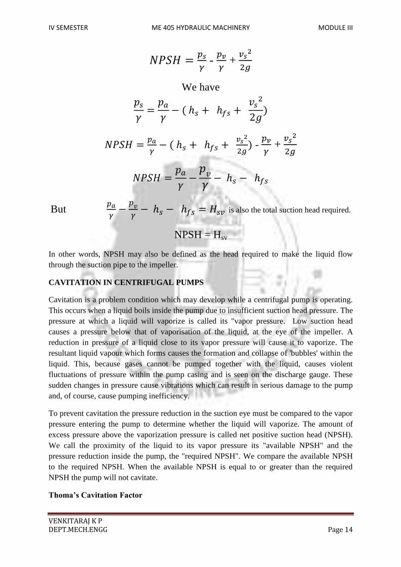
The net positive suction head ( or NPSH) is defined as the absolute pressure head at the inlet to the pump, minus the vapour pressure head corresponding to the temperature of the liquid being pumped, plus the velocity head at this point.
IV SEMESTER ME 405 HYDRAULIC MACHINERY MODULE III
VENKITARAJ K P
DEPT.MECH.ENGG Page 14
- +
We have - +
But
is also the total suction head required.
NPSH = Hsv
In other words, NPSH may also be defined as the head required to make the liquid flow through the suction pipe to the impeller.
CAVITATION IN CENTRIFUGAL PUMPS
Cavitation is a problem condition which may develop while a centrifugal pump is operating. This occurs when a liquid boils inside the pump due to insufficient suction head pressure. The pressure at which a liquid will vaporize is called its "vapor pressure. Low suction head causes a pressure below that of vaporisation of the liquid, at the eye of the impeller. A reduction in pressure of a liquid close to its vapor pressure will cause it to vaporize. The resultant liquid vapour which forms causes the formation and collapse of 'bubbles' within the liquid. This, because gases cannot be pumped together with the liquid, causes violent fluctuations of pressure within the pump casing and is seen on the discharge gauge. These sudden changes in pressure cause vibrations which can result in serious damage to the pump and, of course, cause pumping inefficiency.
To prevent cavitation the pressure reduction in the suction eye must be compared to the vapor pressure entering the pump to determine whether the liquid will vaporize. The amount of excess pressure above the vaporization pressure is called net positive suction head (NPSH). We call the proximity of the liquid to its vapor pressure its "available NPSH" and the pressure reduction inside the pump, the "required NPSH". We compare the available NPSH to the required NPSH. When the available NPSH is equal to or greater than the required NPSH the pump will not cavitate.
Thoma’s Cavitation Factor
IV SEMESTER ME 405 HYDRAULIC MACHINERY MODULE III
VENKITARAJ K P
DEPT.MECH.ENGG Page 15
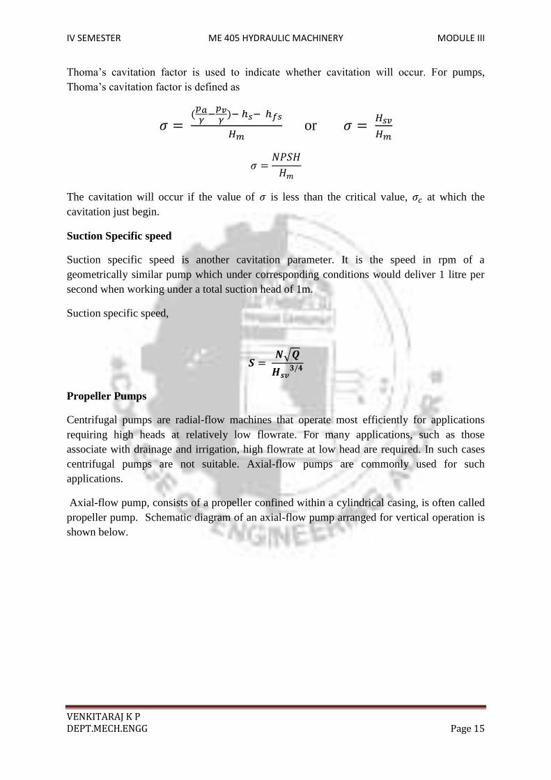
Thoma’s cavitation factor is used to indicate whether cavitation will occur. For pumps, Thoma’s cavitation factor is defined as or
The cavitation will occur if the value of is less than the critical value, at which the cavitation just begin.
Suction Specific speed
Suction specific speed is another cavitation parameter. It is the speed in rpm of a geometrically similar pump which under corresponding conditions would deliver 1 litre per second when working under a total suction head of 1m.
Suction specific speed,
Propeller Pumps
Centrifugal pumps are radial-flow machines that operate most efficiently for applications requiring high heads at relatively low flowrate. For many applications, such as those associate with drainage and irrigation, high flowrate at low head are required. In such cases centrifugal pumps are not suitable. Axial-flow pumps are commonly used for such applications.
Axial-flow pump, consists of a propeller confined within a cylindrical casing, is often called propeller pump. Schematic diagram of an axial-flow pump arranged for vertical operation is shown below.

IV SEMESTER ME 405 HYDRAULIC MACHINERY MODULE III
VENKITARAJ K P
DEPT.MECH.ENGG Page 16
A rotor is connected to a motor through a shaft. As the rotor rotates the fluid is sucked in through the inlet.
For axial pump, u1=u2 =u ,
Work done per unit weight of the liquid,
For maximum energy transfer, Vw1 =0
IV SEMESTER ME 405 HYDRAULIC MACHINERY MODULE III
VENKITARAJ K P
DEPT.MECH.ENGG Page 17
Pump Characteristics
The hydraulic properties of a pump can be described by some characteristics:
1. Q-H curve
2. Efficiency curve
3. Power curve
4. Net Positive Suction Head (NPSH) curve.
Q-H curve
The Q-H curve is the relation between the volume flow and the pressure at a constant speed of the pump crank. The H in the curve is the difference in energy level between the suction and the pressure side of the pump. Q-H curves will be given by the manufacturer of the pump and can normally be considered as a simple quadratic curve.
Efficiency curve
The hydraulic efficiency of the pump with the motor is given with the efficiency curve. The hydraulic efficiency is the relation between the absorbed hydraulic energy (pressure and velocity) and the provided mechanical energy at the pump crank including the power efficiency of the motor.

IV SEMESTER ME 405 HYDRAULIC MACHINERY MODULE III
VENKITARAJ K P
DEPT.MECH.ENGG Page 18
NPSH curve
The Net Positive Suction Head curve is the relation between the volume flow Q and the needed margin between the energy level at the suction side of the pump and the vapour pressure of the water to prevent too much cavitation in the pump. At the suction side of pump negative pressures, i.e. pressures below the atmospheric pressure, can occur, especially when the actual weir of the pump is above the level of the reservoir the water is drawn from. This negative pressure is limited to the actual vapour pressure of the fluid at the current temperature. If this allowable negative pressure is subsided, cavitations will take place in the pump. Although a small amount of cavitations within a pump cannot be avoided, this should be limited. The NPSH requirements of a pump give these limitations. The effect of cavitation is extra wearing of the pump, which can be unacceptable. The bubbles that are formed at the suction side of the pump will be pressurised at the outlet side. The pressurised bubbles will act as actual grains or small stones and wear the material out. To avoid unacceptable cavitations the available NPSH should be larger or equal to the needed NPSH.
System curve
A fluid flow system can in general be characterized with the System Curve

IV SEMESTER ME 405 HYDRAULIC MACHINERY MODULE III
VENKITARAJ K P
DEPT.MECH.ENGG Page 19
Pump Performance Curve
The pump characteristic is normally described graphically by the manufacturer as a pump performance curve. The pump curve describes the relation between flowrate and head for the actual pump. Other important information for proper pump selection is also included - efficiency curves, NPSH curve, pump curves for several impeller diameters and different speeds, and power consumption
A pump can be selected by combining the System Curve and the Pump Curve:
The operating point is where the system curve and the actual pump curve intersect

IV SEMESTER ME 405 HYDRAULIC MACHINERY MODULE III
VENKITARAJ K P
DEPT.MECH.ENGG Page 20
Characteristics of a centrifugal pump
The characteristic of a centrifugal pump at constant speed is shown in Figure. It may be noted that the power increases and decreases after the rated capacity. In this way the pump is self limiting in power and the choice of the motor is made easy. The distance between the brake power and water power curves gives the losses.
Centrifugal pump characteristics at constant speed
The pump characteristics at various speeds including efficiency contours in shown in Figure Such a plot helps in the development of a pump, particularly in specifying the head and flow rates.

IV SEMESTER ME 405 HYDRAULIC MACHINERY MODULE III
VENKITARAJ K P
DEPT.MECH.ENGG Page 21
Characteristics at various speeds


![First Revision No. 147-NFPA 20-2013 [ Global Input ] · PDF fileANSI/HI 1.1-1.2, Rotodynamic (Centrifugal) Pumps for Nomenclature and Definitions, 2008. ANSI/HI 1.3, Rotodynamic (Centrifugal)](https://static.fdocuments.in/doc/165x107/5a7666977f8b9a9c548d4179/first-revision-no-147-nfpa-20-2013-global-input-a-ansihi-11-12-rotodynamic.jpg)