
ROTATING MACHINERY SERVICES, INC. · 2014-04-28 · Rotating Machinery Services, Inc. will host the...
8
Booths 54 & 756 VOLUME 6, ISSUE 3 ROTATING MACHINERY SERVICES, INC. What’s Inside Rule of Thumb 2 Preparing for “The Real World” 2 Steam Turbine Over Speed Trip 3 RMS Adding Tools of the Trade, Part 2 4 Spreader Tool for Assembly/Disassembly of a Centrifugal Compressor 4 Shipboard Turbocharger RCFA 4 Identifying Interferences on the Interference Diagram 5 Dresser-Rand GT61 Power Turbine Component Restoration 6 RMS “The Solution” - Expander Emergency Turnaround 6 RMS Power Solutions Capabilities 7 RMS Welcomes 8 API 687 ROTOR REPAIR SEMINAR Rotating Machinery Services, Inc. Bethlehem, PA NOVEMBER 1 - 5, 2010 July - September 2010 T h e F i n i s h L i n e Phone 484-821-0702 Fax 484-821-0710 www.rotatingmachinery.com 39TH TURBOMACHINERY SYMPOSIUM GEORGE R. BROWN CONVENTION CENTER HOUSTON, TEXAS OCT. 4 - 7, 2010 Rotating Machinery Services, Inc. will be attending and exhibiting at the 39th Turbomachinery Symposium, held at the George Brown Convention Center in Houston, Texas on October 4 - 7. 2010 has been a busy and productive year for Rotating Machinery Services, Inc. There is much to share with our customers, suppliers and friends. We have many new projects in the works, acquired more advanced equipment, added more technical expertise and our expansion has been completed!! Please stop by our booth to say hello and let us fill you in on what’s new! Rotating Machinery Services, Inc. will host the API 687 Rotor Repair Course at our Bethle- hem, PA office on November 1-5, 2010. The course will be taught by Cliff Cook. The API Rotor Repair Course based on API standard 687, covers the minimum requirements for the inspection and repair of rotating equipment rotors, bearings and couplings used in the petroleum, chemical and gas industry services. RMS Engineer Tony Rubino contributed to the writing of the API 687 standard. For more information or to register, please visit the API website at: www.api.u.org/rotorrepair.html The Marriott Courtyard at 2220 Emrick Boulevard, Bethlehem PA (610-625-9500) located 2 blocks from our Office is offering a special rate of $99.00 per night for the API Confer- ence. Please mention API 687 Conference / Rotating Machinery Services, Inc. when making your hotel reservations. If you have any questions about the conference, you can contact Matthew Cunningham, API Events Manager at 202-682-8158 or Kathy Ehasz, RMS Event Coordinator at 484-821-0702.
Transcript of ROTATING MACHINERY SERVICES, INC. · 2014-04-28 · Rotating Machinery Services, Inc. will host the...
Booths
54 & 756
VOLUME 6, ISSUE 3
ROTATING MACHINERY SERVICES, INC.
What’s Inside
Rule of Thumb
2
Preparing for “The Real
World”
2
Steam Turbine Over Speed Trip
3
RMS Adding Tools of the Trade, Part 2
4
Spreader Tool for Assembly/Disassembly
of a Centrifugal Compressor
4
Shipboard Turbocharger
RCFA
4
Identifying Interferences on the Interference
Diagram 5
Dresser-Rand GT61
Power Turbine Component Restoration
6
RMS “The Solution” - Expander Emergency
Turnaround
6
RMS Power Solutions Capabilities 7
RMS Welcomes 8
������
API 687 ROTOR REPAIR SEMINAR
Rotating Machinery Services, Inc. Bethlehem, PA
NOVEMBER 1 - 5, 2010
July - September 2010
The Finish Line Phone 484-821-0702 Fax 484-821-0710 www.rotatingmachinery.com
39TH TURBOMACHINERY SYMPOSIUM
GEORGE R. BROWN CONVENTION CENTER HOUSTON, TEXAS
OCT. 4 - 7, 2010
Rotating Machinery Services, Inc. will be attending and exhibiting at the 39th Turbomachinery Symposium, held at the George Brown Convention Center in Houston, Texas on October 4 - 7. 2010 has been a busy and productive year for Rotating
Machinery Services, Inc. There is much to share with our customers, suppliers and friends. We have many new projects in the works, acquired more advanced equipment, added more technical expertise and our expansion has been completed!! Please stop by our booth to say hello and let us fill you in on what’s new!
Rotating Machinery Services, Inc. will host the API 687 Rotor Repair Course at our Bethle-hem, PA office on November 1-5, 2010. The course will be taught by Cliff Cook. The API Rotor Repair Course based on API standard 687, covers the minimum requirements for the inspection and repair of rotating equipment rotors, bearings and couplings used in the petroleum, chemical and gas industry services. RMS Engineer Tony Rubino contributed to the writing of the API 687 standard. For more information or to register, please visit the API website at: www.api.u.org/rotorrepair.html The Marriott Courtyard at 2220 Emrick Boulevard, Bethlehem PA (610-625-9500) located 2 blocks from our Office is offering a special rate of $99.00 per night for the API Confer-ence. Please mention API 687 Conference / Rotating Machinery Services, Inc. when making your hotel reservations. If you have any questions about the conference, you can contact Matthew Cunningham, API Events Manager at 202-682-8158 or Kathy Ehasz, RMS Event Coordinator at 484-821-0702.
������ Page 2 ROTATING MACHINERY SERVICES, INC.
RULE OF THUMB - TURBOMACHINERY By Neal Wikert
H2S Service: Alloy Steel / 410 SS / 17-4PH: All three materials are acceptable at different strength levels. Low alloy steels like 4330 could be used to HRC 22 max (UTS app. 113 ksi max), 410 stainless steel can be used up to HRC 25 (UTS app. 126 ksi) and 17-4PH can be used up to 33 HRC (UTS app. 140 ksi). These limits are outlined in NACE MR0175. Corrosion resistance is in the same order. 17-4PH is the material of choice if there is any chance of H2S reacting to form H2SO4, or any other corrosive byprod-uct, in a particular stage(s).
Impeller manufacturing notes: Double Temper weld procedure for H2S service: 1600F normalize w/ oil quench First temper: 1225F +/-15 F Second Temper: 1175 to 1200F
Impeller Repair Notes:
Impeller Bore Repair API687: Welding and thermal spraying are the only accepted methods. Chrome or nickel plating is strictly for-bidden due to the difference in thermal growth coefficients. Thermal spray coatings have recommended fin-ished thickness limits as follows:
7-25 mils for high velocity fuel processes and
3-10 mils for combustion processes
Vibration - Common Causes:
Unbalance – Most common cause of vibration. Frequency is 1 per running speed. Bent Shaft – Predominantly 1 per running speed, sometimes 2 times. It is accompanied by a high axial vibration compo-
nent. Bearings, Sleeve – Excessive clearance will result in vibration with a frequency of 1 times running speed. Misalignment – Will result in a vibration with a frequency that can be 1, 2, or 3 times running speed. It is accompanied
by a high axial vibration and may be as high as 1.5 times the vertical or horizontal readings. Oil Whip – May occur in lightly loaded sleeve bearings. The frequency of vibration is sub synchronous (below running
speed)
Looseness – Mechanical looseness will result in a vibration with a frequency 2 times the running speed.
PREPARING TO TRANSITION FROM TEXT BOOKS TO “The Real World” By John Smolko
For most students, college is a mixture of social life, homework and exams. How much emphasis is placed on each of these components can vary greatly from student to student. From my perspective, another component should be added that will help the student transition from the college mindset to the work force. Preparing for life after school was a critical part of my college career. I had the opportunity to participate in a co-op program that gave me an insight into what “The Real World” was all about be-fore I graduated. By working full-time during my academic career, I gained valuable experience that built my resume and prepared me to go straight from graduation into the work force. I also believe the best starting point for a recent graduate is with a company like RMS that is willing to dedicate valuable time and expertise in order to train an entry level employee. After all, success begins with preparation, no matter if you’re preparing for an exam or a turbomachinery overhaul.
STEAM TURBINE OVER SPEED TRIP By Sydney Gross
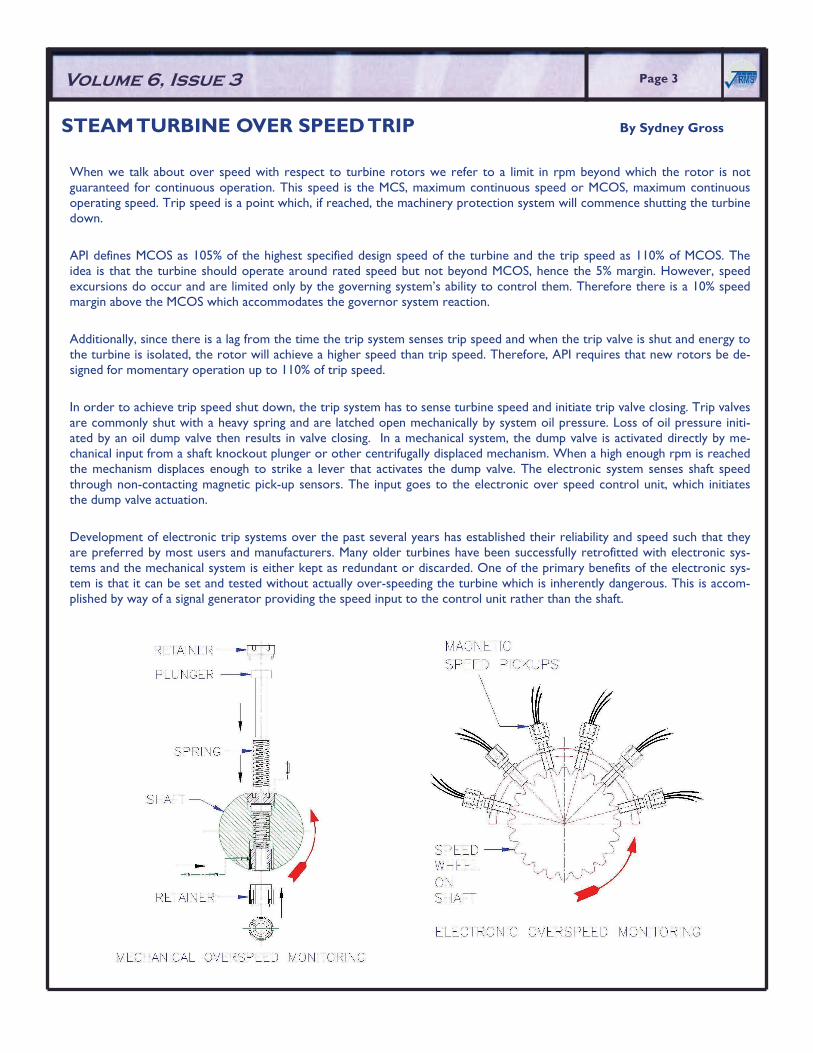
When we talk about over speed with respect to turbine rotors we refer to a limit in rpm beyond which the rotor is not guaranteed for continuous operation. This speed is the MCS, maximum continuous speed or MCOS, maximum continuous operating speed. Trip speed is a point which, if reached, the machinery protection system will commence shutting the turbine down. API defines MCOS as 105% of the highest specified design speed of the turbine and the trip speed as 110% of MCOS. The idea is that the turbine should operate around rated speed but not beyond MCOS, hence the 5% margin. However, speed excursions do occur and are limited only by the governing system’s ability to control them. Therefore there is a 10% speed margin above the MCOS which accommodates the governor system reaction. Additionally, since there is a lag from the time the trip system senses trip speed and when the trip valve is shut and energy to the turbine is isolated, the rotor will achieve a higher speed than trip speed. Therefore, API requires that new rotors be de-signed for momentary operation up to 110% of trip speed. In order to achieve trip speed shut down, the trip system has to sense turbine speed and initiate trip valve closing. Trip valves are commonly shut with a heavy spring and are latched open mechanically by system oil pressure. Loss of oil pressure initi-ated by an oil dump valve then results in valve closing. In a mechanical system, the dump valve is activated directly by me-chanical input from a shaft knockout plunger or other centrifugally displaced mechanism. When a high enough rpm is reached the mechanism displaces enough to strike a lever that activates the dump valve. The electronic system senses shaft speed through non-contacting magnetic pick-up sensors. The input goes to the electronic over speed control unit, which initiates the dump valve actuation. Development of electronic trip systems over the past several years has established their reliability and speed such that they are preferred by most users and manufacturers. Many older turbines have been successfully retrofitted with electronic sys-tems and the mechanical system is either kept as redundant or discarded. One of the primary benefits of the electronic sys-tem is that it can be set and tested without actually over-speeding the turbine which is inherently dangerous. This is accom-plished by way of a signal generator providing the speed input to the control unit rather than the shaft.
Volume 6, Issue 3 ������Page 3
Page 4 ������Page 4 ������ ROTATING MACHINERY SERVICES, INC.
RMS ADDING TO OUR TOOLS OF THE TRADE, Part 2 By Barry Ruch
In continuance to last issue’s article, with the purchase of the Coordinate Measuring Machine behind us, new developments of improvement are in the works. RMS is now laying out a floor plan to construct a climate controlled inspection room. This room will be located in the Shop Area and will be approximately 24’ x 40’. Along with the CMM, it will house all in-spection tools, including two granite inspection tables, 4’ x 6’ and 5 1/2’ x 8’ and ensure not only a clean environment but also a constant temperature, which will further increase the accuracy of dimensional results of parts being reverse engi-neered.
Our years of experience in dimensional inspection have shown that extreme hot or cold conditions in which parts may be inspected can influence part geometry sizes.
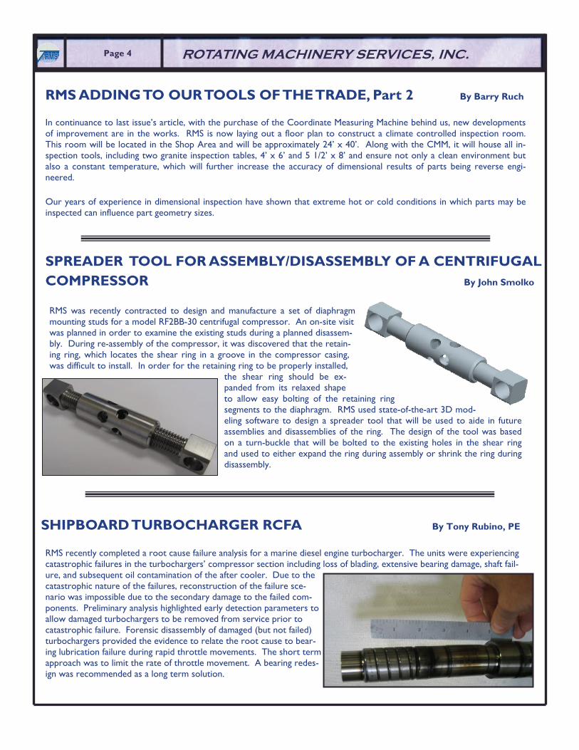
RMS was recently contracted to design and manufacture a set of diaphragm mounting studs for a model RF2BB-30 centrifugal compressor. An on-site visit was planned in order to examine the existing studs during a planned disassem-bly. During re-assembly of the compressor, it was discovered that the retain-ing ring, which locates the shear ring in a groove in the compressor casing, was difficult to install. In order for the retaining ring to be properly installed,
the shear ring should be ex-panded from its relaxed shape to allow easy bolting of the retaining ring segments to the diaphragm. RMS used state-of-the-art 3D mod-eling software to design a spreader tool that will be used to aide in future assemblies and disassemblies of the ring. The design of the tool was based on a turn-buckle that will be bolted to the existing holes in the shear ring and used to either expand the ring during assembly or shrink the ring during disassembly.
SPREADER TOOL FOR ASSEMBLY/DISASSEMBLY OF A CENTRIFUGAL COMPRESSOR By John Smolko
RMS recently completed a root cause failure analysis for a marine diesel engine turbocharger. The units were experiencing catastrophic failures in the turbochargers’ compressor section including loss of blading, extensive bearing damage, shaft fail-ure, and subsequent oil contamination of the after cooler. Due to the catastrophic nature of the failures, reconstruction of the failure sce-nario was impossible due to the secondary damage to the failed com-ponents. Preliminary analysis highlighted early detection parameters to allow damaged turbochargers to be removed from service prior to catastrophic failure. Forensic disassembly of damaged (but not failed) turbochargers provided the evidence to relate the root cause to bear-ing lubrication failure during rapid throttle movements. The short term approach was to limit the rate of throttle movement. A bearing redes-ign was recommended as a long term solution.
SHIPBOARD TURBOCHARGER RCFA By Tony Rubino, PE
������Page 5 Volume 6, Issue 3
In this installment of articles on the interference diagram we will see how interferences are identified. To do this we will look at a situation that often arises as part of a turbomachinery re-rate.
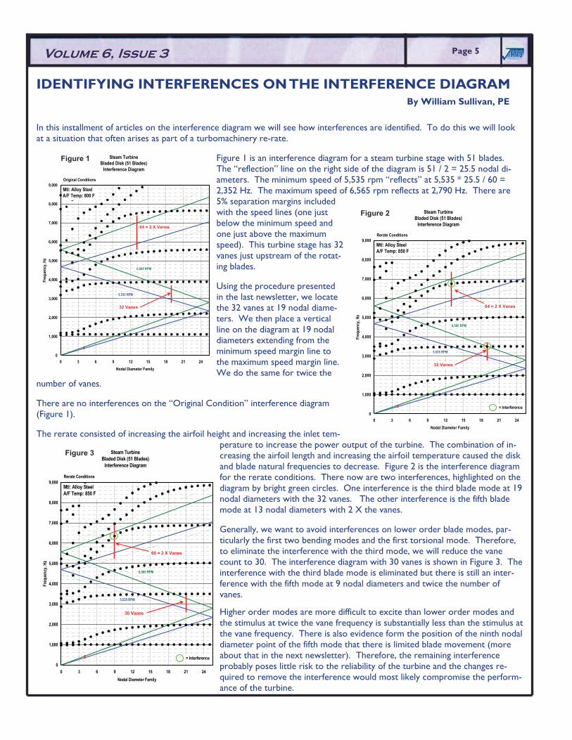
Figure 1 is an interference diagram for a steam turbine stage with 51 blades. The “reflection” line on the right side of the diagram is 51 / 2 = 25.5 nodal di-ameters. The minimum speed of 5,535 rpm “reflects” at 5,535 * 25.5 / 60 = 2,352 Hz. The maximum speed of 6,565 rpm reflects at 2,790 Hz. There are 5% separation margins included with the speed lines (one just below the minimum speed and one just above the maximum speed). This turbine stage has 32 vanes just upstream of the rotat-ing blades.
Using the procedure presented in the last newsletter, we locate the 32 vanes at 19 nodal diame-ters. We then place a vertical line on the diagram at 19 nodal diameters extending from the minimum speed margin line to the maximum speed margin line. We do the same for twice the
number of vanes.
There are no interferences on the “Original Condition” interference diagram (Figure 1).
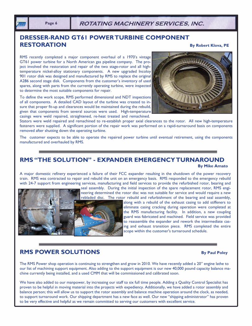
The rerate consisted of increasing the airfoil height and increasing the inlet tem-perature to increase the power output of the turbine. The combination of in-creasing the airfoil length and increasing the airfoil temperature caused the disk and blade natural frequencies to decrease. Figure 2 is the interference diagram for the rerate conditions. There now are two interferences, highlighted on the diagram by bright green circles. One interference is the third blade mode at 19 nodal diameters with the 32 vanes. The other interference is the fifth blade mode at 13 nodal diameters with 2 X the vanes.
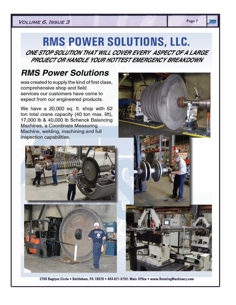
Generally, we want to avoid interferences on lower order blade modes, par-ticularly the first two bending modes and the first torsional mode. Therefore, to eliminate the interference with the third mode, we will reduce the vane count to 30. The interference diagram with 30 vanes is shown in Figure 3. The interference with the third blade mode is eliminated but there is still an inter-ference with the fifth mode at 9 nodal diameters and twice the number of vanes.
Higher order modes are more difficult to excite than lower order modes and the stimulus at twice the vane frequency is substantially less than the stimulus at the vane frequency. There is also evidence form the position of the ninth nodal diameter point of the fifth mode that there is limited blade movement (more about that in the next newsletter). Therefore, the remaining interference probably poses little risk to the reliability of the turbine and the changes re-quired to remove the interference would most likely compromise the perform-ance of the turbine.
Steam TurbineBladed Disk (51 Blades)
Interference Diagram
0
1,000
2,000
3,000
4,000
5,000
6,000
7,000
8,000
9,000
0 3 6 9 12 15 18 21 24Nodal Diameter Family
Freq
uenc
y, Hz
Mtl: Alloy SteelA/F Temp: 800 F
6,565 RPM
5,535 RPM
Original Conditions
64 = 2 X Vanes
32 Vanes
Steam TurbineBladed Disk (51 Blades)
Interference Diagram
0
1,000
2,000
3,000
4,000
5,000
6,000
7,000
8,000
9,000
0 3 6 9 12 15 18 21 24Nodal Diameter Family
Freq
uenc
y, Hz
Mtl: Alloy SteelA/F Temp: 850 F
6,565 RPM
5,535 RPM
Rerate Conditions
64 = 2 X Vanes
32 Vanes
= Interference
Figure 2
Figure 1
IDENTIFYING INTERFERENCES ON THE INTERFERENCE DIAGRAM By William Sullivan, PE
Steam TurbineBladed Disk (51 Blades)
Interference Diagram
0
1,000
2,000
3,000
4,000
5,000
6,000
7,000
8,000
9,000
0 3 6 9 12 15 18 21 24Nodal Diameter Family
Freq
uenc
y, Hz
Mtl: Alloy SteelA/F Temp: 850 F
6,565 RPM
5,535 RPM
Rerate Conditions
60 = 2 X Vanes
30 Vanes
= Interference
Figure 3
RMS “THE SOLUTION” - EXPANDER EMERGENCY TURNAROUND By Mike Amato
Page 6 ������Page 6 ������ ROTATING MACHINERY SERVICES, INC.
RMS POWER SOLUTIONS By Paul Poley
The RMS Power shop operation is continuing to strengthen and grow in 2010. We have recently added a 20” engine lathe to our list of machining support equipment. Also adding to the support equipment is our new 40,000 pound capacity balance ma-chine currently being installed, and a used CMM that will be commissioned and calibrated soon.
We have also added to our manpower, by increasing our staff to six full time people. Adding a Quality Control Specialist has proven to be helpful in moving material into the projects with expediency. Additionally, we have added a rotor assembly and balance person; this will allow us to support the rotor assembly and balance machine operation around the clock, as needed, to support turnaround work. Our shipping department has a new face as well. Our new “shipping administrator” has proven to be very effective and helpful as we remain committed to serving our customers with excellent service.
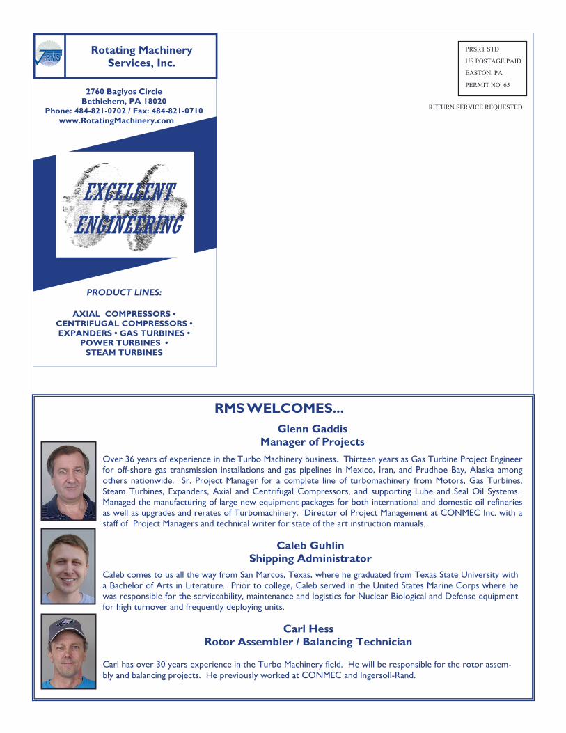
RMS recently completed a major component overhaul of a 1970’s vintage GT61 power turbine for a North American gas pipeline company. The pro-ject involved the restoration and repair of the two stage-rotor and all high-temperature nickel-alloy stationary components. A new upgraded Incoloy 901 rotor disk was designed and manufactured by RMS to replace the original A286 second stage disk. Components from the customer’s inventory of used spares, along with parts from the currently operating turbine, were inspected to determine the most suitable components for repair.
To define the work scope, RMS performed dimensional and NDT inspections of all components. A detailed CAD layout of the turbine was created to in-sure that proper fit-up and clearances would be maintained during the rebuild, given that components from several sources were used. High-temperature casings were weld repaired, straightened, re-heat treated and remachined. Stators were weld repaired and remachined to re-establish proper axial clearances to the rotor. All new high-temperature fasteners were supplied. A significant portion of the repair work was performed on a rapid-turnaround basis on components removed after shutting down the operating turbine.
The customer expects to be able to operate the repaired power turbine until eventual retirement, using the components manufactured and overhauled by RMS.
DRESSER-RAND GT61 POWER TURBINE COMPONENT RESTORATION By Robert Klova, PE
A major domestic refinery experienced a failure of their FCC expander resulting in the shutdown of the power recovery train. RMS was contracted to repair and rebuild the unit on an emergency basis. RMS responded to the emergency rebuild with 24-7 support from engineering services, manufacturing and field services to provide the refurbished rotor, bearing and
seal assembly. During the initial inspection of the spare replacement rotor, RMS engi-neering determined the rotor disc was not suitable for service and would require a new rebladed disc. The rotor rebuild and refurbishment of the bearing and seal assembly,
along with a rebuild of the exhaust casing to add stiffeners to eliminate casing cracking during operation were completed at the RMS manufacturing facility. In addition, a new coupling guard was fabricated and machined. Field service was provided to reassemble the expander and rework the intermediate cas-ing and exhaust transition piece. RMS completed the entire scope within the customer's turnaround schedule.
������Page 7 Volume 6, Issue 3
Caleb Guhlin Shipping Administrator
Caleb comes to us all the way from San Marcos, Texas, where he graduated from Texas State University with a Bachelor of Arts in Literature. Prior to college, Caleb served in the United States Marine Corps where he was responsible for the serviceability, maintenance and logistics for Nuclear Biological and Defense equipment for high turnover and frequently deploying units.
2760 Baglyos Circle Bethlehem, PA 18020
Phone: 484-821-0702 / Fax: 484-821-0710 www.RotatingMachinery.com
Rotating Machinery Services, Inc. ������
PRODUCT LINES:
AXIAL COMPRESSORS • CENTRIFUGAL COMPRESSORS • EXPANDERS • GAS TURBINES •
POWER TURBINES • STEAM TURBINES
PRSRT STD
US POSTAGE PAID
EASTON, PA
PERMIT NO. 65
RETURN SERVICE REQUESTED
EXCELLENT ENGINEERING
RMS WELCOMES...
Carl Hess Rotor Assembler / Balancing Technician
Carl has over 30 years experience in the Turbo Machinery field. He will be responsible for the rotor assem-bly and balancing projects. He previously worked at CONMEC and Ingersoll-Rand.
Glenn Gaddis Manager of Projects
Over 36 years of experience in the Turbo Machinery business. Thirteen years as Gas Turbine Project Engineer for off-shore gas transmission installations and gas pipelines in Mexico, Iran, and Prudhoe Bay, Alaska among others nationwide. Sr. Project Manager for a complete line of turbomachinery from Motors, Gas Turbines, Steam Turbines, Expanders, Axial and Centrifugal Compressors, and supporting Lube and Seal Oil Systems. Managed the manufacturing of large new equipment packages for both international and domestic oil refineries as well as upgrades and rerates of Turbomachinery. Director of Project Management at CONMEC Inc. with a staff of Project Managers and technical writer for state of the art instruction manuals.