Ieee Shaft Voltages & Rotating Machinery
8
SHAFT VOLTAGES & ROTATING MACHINERY Copyright Material IEEE Paper No. PCIC-91-13 WICHAKL J. COSTELLO MEMBER IEEE Magnetic Products and Services, Inc. 15355 Vantage Parkway West, Suite 252 Houston, Texas 77032 ABSTRACT It appears that there has recently been an increase in bearing and seal deterioration in rotating machinery due to shaft voltage and current generation. It is possible that this increase is the result of more knowledge in the detection and recognition of the associated damage. In order to determine whether a machine has shaft voltage problems or the potential for problems, it is important to review the damage types as well as the four potential sources for voltage generation in rotating machinery. Once this is accomplished, it is then possible to perform detailed testing for the detection and analysis of shaft currents so that means for the correction of these damaging currents can be implemented. I. INTRODUCTION Shaft currents have existed in rotating machinery for upwards of 100 years. Why is it then that bearing and seal failures attributed to this phenomenon appear to occur more frequently now than ever before? In electrical machines, the problems are normally associated with the use of poorly insulated or non-insulated bearings or by inadvertently bypassing the insulation by installing non-insulated resistance temperature detectors (RTD's), thermocouples (TC's), or lube oil piping. In other words, the solution has been available for quite some time, but as a result of carelessness, countless failures have occurred. In mechanical machines, the mechanical designer could never have anticipated that shaft currents would invade his machine. However, as he designed turbines and compressors to operate at substantially higher loads and greater speeds, he is at least partly responsible for the proliferation of shaft currents in mechanical trains. This paper will touch on each of the sources of shaft currents and each type of shaft current damage, at least in a cursory manner. Tests for the detection and analysis of shaft currents will be reviewed in detail. 11. SHAFT CURRENT RECOGNITION Probably the best method for determining the presence and severity of shaft currents is through inspection of the affected damaged parts. Quite often the bearings, seals, etc., are replaced during normal maintenance procedures and the machine is placed back into service. Some time later, the parts are looked at more closely and it is only then discovered that they were affected by shaft currents. At this point the job of identifying the cause and eliminating the voltage source is made much more difficult since the machine is up and running thereby eliminating confirming static measurements and corrections. For this reason, it is highly recommended that all damaged parts be inspected and possible voltage sources identified while the machine is still shut down and at least partly disassembled. There are four distinct types of shaft current damage: 1) frosting; 2) spark tracks; 3) pitting; and 4) welding. The first three types of damage must be carefully viewed under a microscope since they are easily and often misdiagnosed as either chemical or mechanical damage. Magnification of between 50-100 times is required for this inspection. 1) Frostinq By far the most common type of shaft current damage. Parts affected are bearings, seals, thrust collars, journals and to a lesser extent, gears. The appearance is that of a sand blasted surface, and if the entire available surface is affected, the damage is not noticeable to the naked eye due to its satin like appearance. [l] When viewed microscopically, however, the frosted surface is seen as very small and individual "craters". The bottom of the craters are very round and shiny, indicative of the melting which had occurred. This frosting occurs during voltage discharge and is commonly referred to as "Electric Discharge Machining" (EDM), or Electrolysis. As EDM occurs, material is removed. Sometimes chemical attack gives a similar appearance to frosting, however, the marks are smaller, not as deep and appear dull. X-ray spectroscopy can be used in order to determine if the surface was contaminated in this manner. Figures 1 through 3 exhibit clear frosting damage while Figure 4 shows an example of corrosion damage from chemical attack, originally believed to be frosting damage. Fig. 1. This is a close-up photograph of a thrust bearing pad from a steam turbine which was driving an air compressor at an oil refinery. The frosting is extremely significant on the trailing edge of the pads. 91-CH3057-7/1/91/0000-0071 $01.00 @ 199 lIEEE 71 -
description
Ieee Shaft Voltages & Rotating Machinery
Transcript of Ieee Shaft Voltages & Rotating Machinery
SHAFT VOLTAGES & ROTATING MACHINERY Copyright Material IEEE Paper No. PCIC-91-13 WICHAKL J. COSTELLO
MEMBER IEEE Magnetic Products and Services, Inc. 15355 Vantage Parkway West, Suite 252
Houston, Texas 77032 ABSTRACT It appears that there has recently been an increase in bearing and seal deterioration in rotating machinery due to shaft voltage and current generation. It is possible that this increase is the result of more knowledge in the detection and recognition of the associated damage.
In order to determine whether a machine has shaft voltage problems or the potential for problems, it is important to review the damage types as well as the four potential sources for voltage generation in rotating machinery. Once this is accomplished, it is then possible to perform detailed testing for the detection and analysis of shaft currents so that means for the correction of these damaging currents can be implemented.
I. INTRODUCTION
Shaft currents have existed in rotating machinery for upwards of 100 years. Why is it then that bearing and seal failures attributed to this phenomenon appear to occur more frequently now than ever before? In electrical machines, the problems are normally associated with the use of poorly insulated or non-insulated bearings or by inadvertently bypassing the insulation by installing non-insulated resistance temperature detectors (RTD's), thermocouples (TC's), or lube oil piping. In other words, the solution has been available for quite some time, but as a result of carelessness, countless failures have occurred.
In mechanical machines, the mechanical designer could never have anticipated that shaft currents would invade his machine. However, as he designed turbines and compressors to operate at substantially higher loads and greater speeds, he is at least partly responsible for the proliferation of shaft currents in mechanical trains.
This paper will touch on each of the sources of shaft currents and each type of shaft current damage, at least in a cursory manner. Tests for the detection and analysis of shaft currents will be reviewed in detail.
11. SHAFT CURRENT RECOGNITION
Probably the best method for determining the presence and severity of shaft currents is through inspection of the affected damaged parts. Quite often the bearings, seals, etc., are replaced during normal maintenance procedures and the machine is placed back into service. Some time later, the parts are looked at more closely and it is only then discovered that they were affected by shaft currents. At this point the job of identifying the cause and eliminating the voltage source is made much more difficult since the machine is up and running thereby eliminating confirming static measurements and corrections. For this reason, it is highly recommended that all damaged parts be inspected and possible voltage sources identified while the machine is still shut down and at least partly disassembled.
There are four distinct types of shaft current damage: 1) frosting; 2) spark tracks; 3) pitting; and 4) welding. The first three types of damage must be carefully viewed under a microscope since they are easily and often misdiagnosed as either chemical or mechanical damage. Magnification of between 50-100 times is required for this inspection.
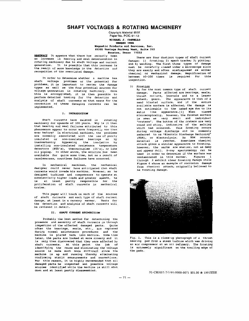
1) Frostinq By far the most common type of shaft current damage. Parts affected are bearings, seals, thrust collars, journals and to a lesser extent, gears. The appearance is that of a sand blasted surface, and if the entire available surface is affected, the damage is not noticeable to the naked eye due to its satin like appearance. [l] When viewed microscopically, however, the frosted surface is seen as very small and individual "craters". The bottom of the craters are very round and shiny, indicative of the melting which had occurred. This frosting occurs during voltage discharge and is commonly referred to as "Electric Discharge Machining" (EDM), or Electrolysis. As EDM occurs, material is removed. Sometimes chemical attack gives a similar appearance to frosting, however, the marks are smaller, not as deep and appear dull. X-ray spectroscopy can be used in order to determine if the surface was contaminated in this manner. Figures 1 through 3 exhibit clear frosting damage while Figure 4 shows an example of corrosion damage from chemical attack, originally believed to be frosting damage.
Fig. 1. This is a close-up photograph of a thrust bearing pad from a steam turbine which was driving an air compressor at an oil refinery. The frosting is extremely significant on the trailing edge of the pads.
91-CH3057-7/1/91/0000-0071 $01.00 @ 199 lIEEE
71 -

Fig. 2. This side view of the thrust pad of Fig. 1 shows the amount of electric discharge machining which had taken place on this as well as all the remaining pads of the bearing.
Fig. 3. A 60 times magnification of the frosted and adjacent noneffected surface on the bearing pad. Note how the craters had overlapped indicative of considerable discharges.
Fig. 4. A 60 times magnification of corrosion damage on a thrust pad. This was originally believed to have been frosting damage however, after examination from a metallurgist, he determined it to be from chlorine attack.
SDark Tracks The initial appearance of these tracks is that of scratches in the babbitted surface from foreign particles in the lubrication or seal oil. A closer examination, however, reveals that they are very irregular in nature and are often askew to the direction of rotation. Under magnification, the bottom of the tracks are sometimes melted, and the corners are sharp, while in contrast a tool or dirt particle would leave rounded corners. The depth of the spark track is generally the same over its entire surface. Figures 5 and 6 show typical spark tracks in a bearing surface.
Fig. 5. This is a close-up of a spark track in a journal bearing surface. Note the jagged character of the track.
Fig. 6. This is a 60 times magnification of a spark track in a journal bearing. Note the molten area in the bottom of the track.
3) Pittinq This damage is listed separately from frosting as it is generally much larger in size (from 1/32" to 1/4") since its source is extremely powerful. It often occurs in gear teeth, on the backs of bearings, or seals and sometimes between frame splits. As opposed to frosting where the entire surface might be affected, pitting occurs more randomly and it is sometimes possible to count the number of discharges. The appearance of the pits are similar to the individual frosting craters, that is, they often have round shiny bottoms.[l] Sometimes, pitting gets confused with fretting type corrosion. In this case, a qualified metallurgist is necessary to distinguish the difference. Figure 7 is an example of pitting type damage.
- 72 -
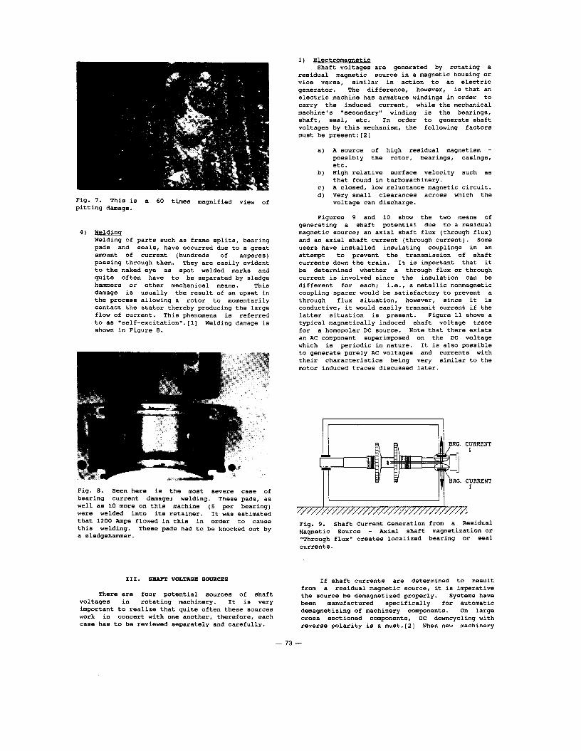
Fig. 7 . This is a 60 times magnified view of pitting damage.
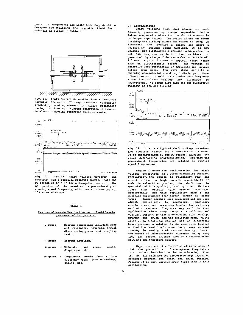
4) Weldinq Welding of parts such as frame splits, bearing pads and seals, have occurred due to a great amount of current (hundreds of amperes) passing through them. They are easily evident to the naked eye as spot welded marks and quite often have to be separated by sledge hammers or other mechanical means. This damage is usually the result of an upset in the process allowing a rotor to momentarily contact the stator thereby producing the large flow of current. This phenomena is referred to as "self-excitation".[l] Welding damage is shown in Figure 8.
Fig. 8. Seen here is the most severe case of bearing current damage; weldina. These DadS. as
1) Electromaanetic Shaft voltages are generated by rotating a
residual magnetic source in a magnetic housing or vice versa, similar in action to an electric generator. The difference, however, is that an electric machine has armature windings in order to carry the induced current, while the mechanical machine's "secondary" winding is the bearings, shaft, seal, etc. In order to generate shaft voltages by this mechanism, the following factors must be present:[2]
a) A source of high residual magnetism - possibly the rotor, bearings, casings, etc.
b) High relative surface velocity such as that found in turbomachinery.
c) A closed, low reluctance magnetic circuit. d) Very small clearances across which the
voltage can discharge.
Figures 9 and 10 show the two means of generating a shaft potential due to a residual magnetic source; an axial shaft flux (through flux) and an axial shaft current (through current). Some users have installed insulating couplings in an attempt to prevent the transmission of shaft currents down the train. It is important that it be determined whether a through flux or through current is involved since the insulation can be different for each; i.e., a metallic nonmagnetic coupling spacer would be satisfactory to prevent a through flux situation, however, since it is conductive, it would easily transmit current if the latter situation is present. Figure 11 shows a typical magnetically induced shaft voltage trace for a homopolar DC source. Note that there exists an AC component superimposed on the DC voltage which is periodic in nature. It is also possible to generate purely AC voltages and currents with their characteristics being very similar to the motor induced traces discussed later.
CURRENT I
CURRENT I
I 1 I I - . well as 10 more on this machine (5 per bearing) I I . . . . . . . . . . . . . . . . . . . . . . . . . . . . . . . . . . . . . . . . . . . . . . . . . . . . . . . . . . . . were welded into its retainer. It was estimated that 1200 Amps flowed in this in order to cause Fig. 9. Shaft Current Generation from a Residual this welding. These pads had to be knocked out by Magnetic Source - Axial shaft magnetization or a sledgehammer. "Through flux" creates localized bearing or Seal
currents.
111. SHAFT VOLTAQE SOURCES If shaft currents are determined to result from a residual magnetic source, it is imperative
There are four potential sources of shaft the source be demagnetized properly. Systems have voltages in rotating machinery. It is very been manufactured specifically for automatic important to realize that quite often these sources demagnetizing of machinery components. On large work in concert with one another, therefore, each cross sectioned components, DC downcycling with case has to be reviewed separately and carefully. reverse polarity is a must.[2] When new machinery
- 73 -
parts or components are installed, they should be demagnetized utilizing the magnetic field level criteria as listed in Table 1.
20
I
r
//////////////////////////////////, Fig. 10. Shaft Current Generation from a Residual Magnetic Source - "Through Current" Generation created by rotating element in highly magnetized casing or housing. Current generation is similar to electric machine generated shaft currents.
m V r m e
X I 105 HZ ml:is / 0 I V 3J Y. 45.87 mvrm.
0 V r m s
START, 0 Hz EWt 4 . 7 7 4 3 Hz STOP, 500 Hz 81 TIMECR)
I
m V a l t
START, 7::v -2 0 Sec : STOP2 800 msec
Fig. 11. Typical shaft voltage waveform and spectrum for a residual magnetic source. Note the DC offset as this is for a Homopolar source. The AC portion of the waveform is predominantly at running speed frequency, which for this machine was 103 Hz or 6180 RPM.
TAaLE 1
Maximum allowable Residual Maanetic Field Levels jas measured in open air)
2 gauss - Bearing components including pads and retainers, journals, thrust disc, seals, gears and coupling teeth.
4 gauss - Bearing housings.
6 gauss - Midshaft and wheel areas, diaphragms, etc.
10 gauss - Components remote from minimum clearance areas, such as casings, piping, etc.
V o l t I I 4
V o l t / O I V
- 1 4 I I START, 0 Sec STOP, 4 0 0 mSec
Fig. 12. This is a typical shaft voltage waveform and spectrum traces for an electrostatic source. It is characterized by its DC offset, charging and rapid discharging characteristics. Note that the predominant frequencies are related to running speed frequencies.
Figure 13 shows the configuration for shaft voltage generation on a steam condensing turbine. Fortunately, the source is relatively weak and cannot deliver a high current to ground.[4] In order to solve this problem, the shaft must be grounded with a quality grounding brush. We have found that bristle type brushes developed specifically for this application have a far superior performance than carbon, copper or brass types. Carbon brushes were developed and are used almost exclusively by electrical machinery manufacturers as commutator brushes for machinery excitation systems. They work very well in that application since they carry a significant and constant current so that a conducting film develops between the brush and the collector ring. Quite often if an electrical machine has an electrical brush problem, a solution is the removal of brushes so that the remaining brushes carry more current thereby increasing their current density. Due to the nature of electrostatic currents being very low, the carbon brushes develop a nonconducting film and are therefore useless.
Experience with the "soft" metallic brushes is that when placed in an oil atmosphere, they behave in an manner identical to that of a bearing; that is, an oil film and its associated high impedance develops between the shaft and brush surface. Figures 14-16 show various brush types used in this application.
- 74 -
I . . . . . . . . . . . . . . . . . . . . . . . . . . . . . . . . . . . . . . . . . . . . . . . . . . . . . . . . . . . . .
Fig. 13. Electrostatic Shaft Voltage Generation - Charge separation of particles elevates shaft to a potential above ground (casing) potential.
Fig. 14. The most reliable grounding brush is a bristle type brush as seen here. The bristles have a negligible voltage drop thereby effectively grounding the shaft.
Fig. 15. This is a carbon type grounding brush installed on a steam turbine. Tests proved that a high impedance film was developing between it and the shaft rendering it useless for this application.
- . . I
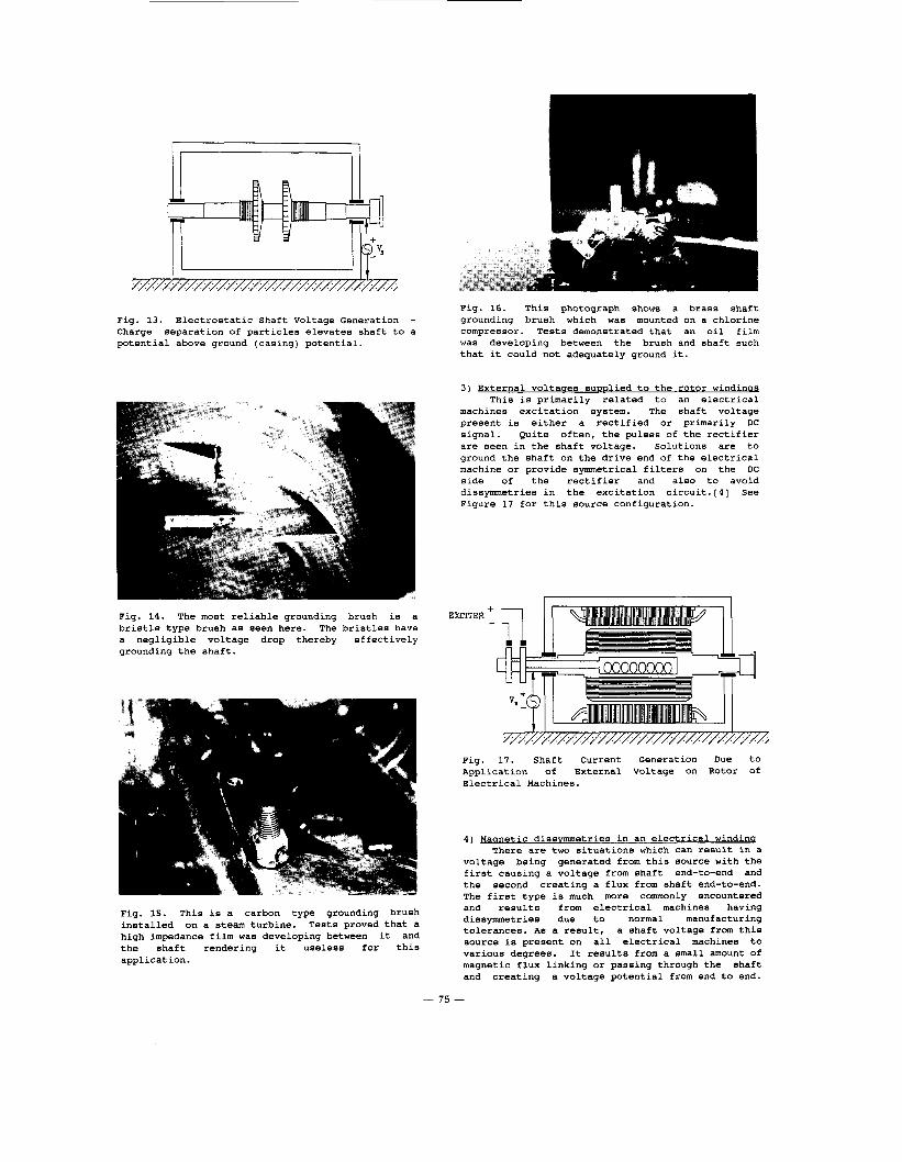
Fig. 16. This photograph shows a brass shaft grounding brush which was mounted on a chlorine compressor. Tests demonstrated that an oil film was developing between the brush and shaft such that it could not adequately ground it.
3) External voltages SuDDlied to the rotor windinos This is primarily related to an electrical
machines excitation system. The shaft voltage present is either a rectified or primarily DC signal. Quite often, the pulses of the rectifier are seen in the shaft voltage. Solutions are to ground the shaft on the drive end of the electrical machine or provide symmetrical filters on the DC side of the rectifier and also to avoid dissymmetries in the excitation circuit.[4] See Figure 17 for this source configuration.
EXCITER ' -
Fig. 17. Shaft Current Generation Due to Application of External Voltage on Rotor of Electrical Machines.
4) Maanetic dissvmmetries in an electrical windinq There are two situations which can result in a
voltage being generated from this source with the first causing a voltage from shaft end-to-end and the second creating a flux from shaft end-to-end. The first type is much more commonly encountered and results from electrical machines having dissymmetries due to normal manufacturing tolerances. As a result, a shaft voltage from this source is present on all electrical machines to various degrees. It results from a small amount of magnetic flux linking or passing through the shaft and creating a voltage potential from end to end.
- 75 -
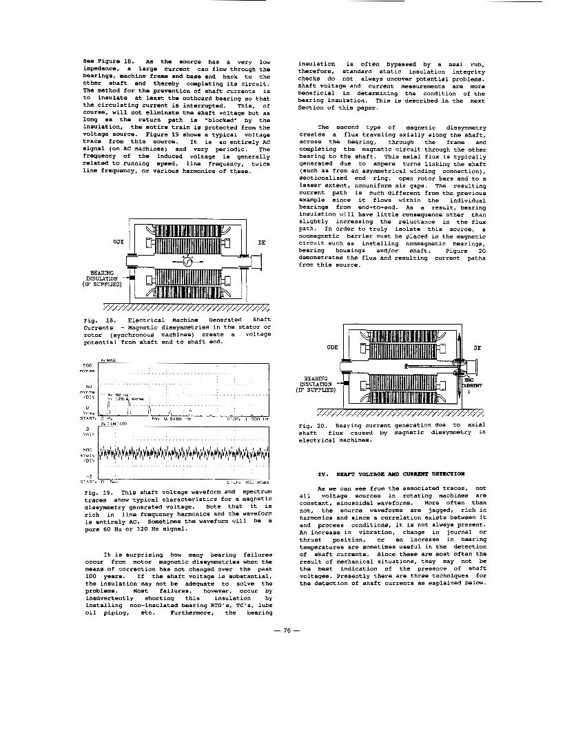
See Figure 18. As the source has a very low impedance, a large current can flow through the bearings, machine frame and base and back to the other shaft end thereby completing its circuit. The method for the prevention of shaft currents is to insulate at least the outboard bearing so that the circulating current is interrupted. This, of course, will not eliminate the shaft voltage but as long as the return path is "blocked" by the insulation, the entire train is protected from the voltage source. Figure 19 shows a typical voltage trace from this source. It is an entirely AC signal (on AC machines) and very periodic. The frequency of the induced voltage is generally related to running speed, line frequency, twice line frequency, or various harmonics of these.
BEARING INSULATION
(IF SUPPLIED)
I I . . . . . . . . . . . . . . . . . . . . . . . . . . . . . . . . . . . . . . . . . . . . . . . . . . . . . . . . . . . . . . . .
Fig. 18. Electrical Machine Generated Shaft Currents - Magnetic dissymmetries in the stator or rotor (synchronous machines) create a voltage potential from shaft end to shaft end.
V r m s L r n 0
START, 0 Hz RW. 9.5485 HZ STOP, 1 000 Hz
500 mVolt
/ D I V I I
START, 0 Sec STOP8 400 mSec
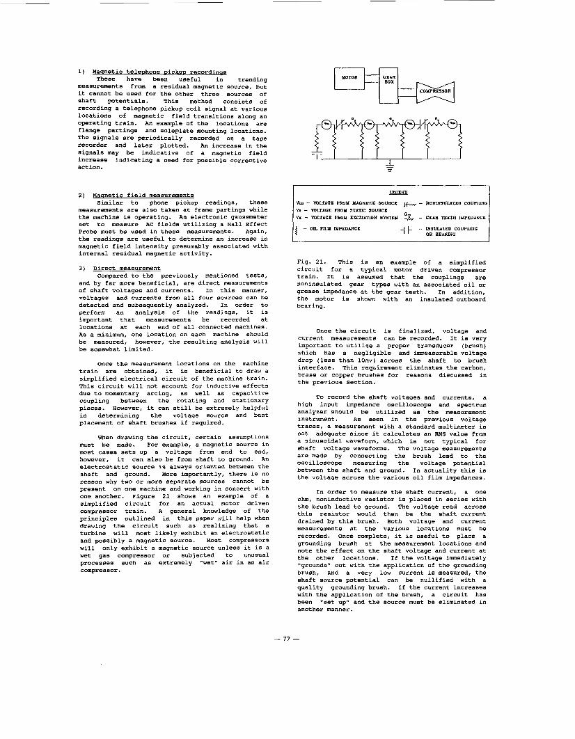
Fig. 19. This shaft voltage waveform and spectrum traces show typical characteristics for a magnetic dissymmetry generated voltage. Note that it is rich in line frequency harmonics and the waveform is entirely AC. Sometimes the waveform will be a pure 60 Hz or 120 Hz signal.
It is surprising how many bearing failures occur from motor magnetic dissymmetries when the means of correction has not changed over the past 100 years. If the shaft voltage is substantial, the insulation may not be adequate to solve the problems. Most failures, however, occur by inadvertently shorting this insulation by installing non-insulated bearing RTD's, TC's, lube oil piping, etc. Furthermore, the bearing
insulation is often bypassed by a seal rub, therefore, standard static insulation integrity checks do not always uncover potential problems. Shaft voltage and current measurements are more beneficial in determining the condition of the bearing insulation. This is described in the next Section of this paper.
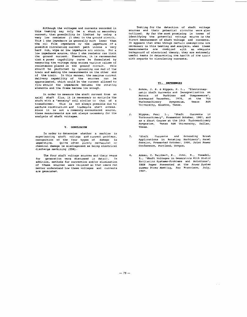
The second type of magnetic dissymmetry creates a flux traveling axially along the shaft, across the bearing, through the frame and completing the magnetic circuit through the other bearing to the shaft. This axial flux is typically generated due to ampere turns linking the shaft (such as from an asymmetrical winding connection), sectionalized end ring, open rotor bars and to a lesser extent, nonuniform air gaps. The resulting current path is much different from the previous example since it flows within the individual bearings from end-to-end. As a result, bearing insulation will have little consequence other than slightly increasing the reluctance in the flux path. In order to truly isolate this source, a nonmagnetic barrier must be placed in the magnetic circuit such as installing nonmagnetic bearings, bearing housings and/or shaft. Figure 20 demonstrates the flux and resulting current paths from this source.
I I ~/////////////////////////////////, . . . . . . . .
Fig. 20. Bearing current generation due to axial shaft flux caused by magnetic dissymmetry in electrical machines.
IV. SHAFT VOLTAQE AND CURRENT DETECTION
As we can see from the associated traces, not all voltage sources in rotating machines are constant, sinusoidal waveforms. More often than not, the source waveforms are jagged, rich in harmonics and since a correlation exists between it and process conditions, it is not always present. An increase in vibration, change in journal or thrust position, or an increase in bearing temperatures are sometimes useful in the detection of shaft currents. Since these are most often the result of mechanical situations, they may not be the best indication of the presence of shaft voltages. Presently there are three techniques for the detection of shaft currents as explained below.
- 76 -
1) Maanetic telephone DickuD recordinas These have been useful in trending
measurements from a residual magnetic source, but it cannot be used for the other three sources of shaft potentials. This method consists of recording a telephone pickup coil signal at various locations of magnetic field transitions along an operating train. An example of the locations are flange partings and soleplate mounting locations. The signals are periodically recorded on a tape recorder and later plotted. An increase in the signals may be indicative of a magnetic field increase indicating a need for possible corrective act ion.
2) Maanetic field measurements Similar to phone pickup readings, these
measurements are also taken at frame partings while the machine is operating. An electronic gaussmeter set to measure AC fields utilizing a Hall Effect Probe must be used in these measurements. Again, the readings are useful to determine an increase in magnetic field intensity presumably associated with internal residual magnetic activity.
3) Direct measurement Compared to the previously mentioned tests,
and by far more beneficial, are direct measurements of shaft voltages and currents. In this manner, voltages and currents from all four sources can be detected and subsequently analyzed. In order to perform an analysis of the readings, it is important that measurements be recorded at locations at each end of all connected machines. As a minimum, one location on each machine should be measured, however, the resulting analysis will be somewhat limited.
Once the measurement locations on the machine train are obtained, it is beneficial to draw a simplified electrical circuit of the machine train. This circuit will not account for inductive effects due to momentary arcing, as well as capacitive coupling between the rotating and stationary pieces. However, it can still be extremely helpful in determining the voltage source and best placement of shaft brushes if required.
When drawing the circuit, certain assumptions must be made. For example, a magnetic source in most cases sets up a voltage from end to end, however, it can also be from shaft to ground. An electrostatic source is always oriented between the shaft and ground. More importantly, there is no reason why two or more separate sources cannot be present on one machine and working in concert with one another. Figure 21 shows an example of a simplified circuit for an actual motor driven compressor train. A general knowledge of the principles outlined in this paper will help when drawing the circuit such as realizing that a turbine will most likely exhibit an electrostatic and possibly a magnetic source. Most compressors will only exhibit a magnetic source unless it is a wet gas compressor or subjected to unusual processes such as extremely "wet" air in an air compressor.
i# ? O Y k COYPRESSOR
Vm - VOLTAGE FROY MAGNETIC SOURCE Va - VOLTAGE FROY STATIC SOURCE
Vx - VOLTAGE FROY EXCITATION SYSTEY
+ - NONIHSULATED COUPLING
& - G E A R TCEIl1 IMPEDANCE
-1 /- - INSULATED COUPUNG OR BEARING
Fig. 21. This is an example of a simplified circuit for a typical motor driven compressor train. It is assumed that the couplings are noninsulated gear types with an associated oil or grease impedance at the gear teeth. In addition, the motor is shown with an insulated outboard bearing.
Once the circuit is finalized, voltage and current measurements can be recorded. It is very important to utilize a proper transducer (brush) which has a negligible and immeasurable voltage drop (less than 10mv) across the shaft to brush interface. This requirement eliminates the carbon, brass or copper brushes for reasons discussed in the previous Section.
To record the shaft voltages and currents, a high input impedance oscilloscope and spectrum analyzer should be utilized as the measurement instrument. As seen in the previous voltage traces, a measurement with a standard multimeter is not adequate since it calculates an RMS value from a sinusoidal waveform, which is not typical for shaft voltage waveforms. The voltage measurements are made by connecting the brush lead to the oscilloscope measuring the voltage potential between the shaft and ground. In actuality this is the voltage across the various oil film impedances.
In order to measure the shaft current, a one ohm, noninductive resistor is placed in series with the brush lead to ground. The voltage read across this resistor would then be the shaft current drained by this brush. Both voltage and current measurements at the various locations must be recorded. Once complete, it is useful to place a grounding brush at the measurement locations and note the effect on the shaft voltage and current at the other locations. If the voltage immediately "grounds" out with the application of the grounding brush, and a very low current is measured, the shaft source potential can be nullified with a quality grounding brush. If the current increases with the application of the brush, a circuit has been "set up" and the source must be eliminated in another manner.
- 77 -
Although the voltages and currents recorded in this testing may only be a shunt or secondary current, that possibility is limited by using a very low resistor (1 ohm) in the ground circuit. This 1 ohm impedance is generally much lower than the oil film impedance or the impedance of a possible circulating current path unless a very hard rub, wipe or low impedance arc occurs. For a low impedance source, this 1 ohm resistor can limit the ground current. Therefore, it is recommended that a power capability curve be formulated by measuring the voltage drop across various values of resistances placed in the ground circuit. This should be performed by grounding one end of the train and making the measurements on the other end of the train. In this manner, the maximum current delivery capability of the sources can be approximated, which would be the current allowed to flow should the impedance between the rotating elements and the frame become low enough.
In order to measure the shaft current from an axial shaft flux, it is necessary to encircle the shaft with a "sensing" coil similar to that of a transformer. This is not always possible due to machine construction and inadequte shaft access. Since it is not a commonly encountered source, these measurements are not always necessary for the analysis of shaft voltages.
V. CONCLUSION
In order to determine whether a machine is experiencing shaft voltage and current problems, recognition of the four types of damage is imperative. Quite often purely mechanical or chemical damage is misdiagnosed as being electrical discharge machining (EDM).
The four shaft voltage sources and their means for generation were discussed in detail. In addition, methods for correction andfor elimination of these sources were reviewed so that users can better understand how these voltages and currents are generated.
Testing for the detection of shaft voltage sources and their potential circuits were also outlined. By far the most promising in terms of identifying the potential voltage source is the direct measurement of shaft voltage and currents. It appears that even though certain assumptions are necessary in this testing and analysis, when these measurements are combined with an adequate background of electrical theory, they are extremely useful tests in determining the health of the train with regards to circulating currents.
VI. REFERENCES
Sohre, J. S. L Nippes, P. I., "Electromag- netic Shaft Currents and Demagnetization on Rotors of Turbines and Compressors", Presented December, 1978, at the 7th Turbomachinery Symposium, Texas ALM University, Houston, Texas.
Nippes, Paul I., "Shaft Currents in Turbomachinery", Presented October, 1987, and as a Short Course at the 16th Turbomachinery Symposium, Texas ALM University, Dallas, Texas.
"Shaft Currents and Grounding Brush Applications in Rotating Machinery", Panel Session, Presented October, 1986, Joint Power Conference, Portland, Oregon.
Amman, C. Reichert, K., Joho, R., Posedel, Z., "Shaft Voltages in Generators With Static Excitation Systems-Problems and Solutions", IEEE Paper Presented at the Power System Summer Power Meeting, San Francisco, July, 1987.
- 78 -