Rotary Screw Compressors ASD Series - About usalmageneralelectric.com/Download/Aria Compressa - Aer...
4
www.kaeser.com Free air delivery 0.87 to 6.26 m³/min, Pressure 5.5 – 15 bar Rotary Screw Compressors ASD Series With the world-renowned SIGMA PROFILE ALMA GENERAL ELECTRIC S.R.L. B-dul Indipendentei nr. 25 Baia Mare 430071 Maramures Tel. 0262-220992 Cel. 0745-911378 [email protected] www.almageneralelectric.com
Transcript of Rotary Screw Compressors ASD Series - About usalmageneralelectric.com/Download/Aria Compressa - Aer...
www.kaeser.com
Free air delivery 0.87 to 6.26 m³/min, Pressure 5.5 – 15 bar
Rotary Screw CompressorsASD SeriesWith the world-renowned SIGMA PROFILE
ALMA GENERAL ELECTRIC S.R.L. B-dul Indipendentei nr. 25Baia Mare 430071 MaramuresTel. 0262-220992Cel. 0745-911378almageneralelectric@gmail.comwww.almageneralelectric.com
www.kaeser.com
2 3
ASD: Long-term savings
ASD series
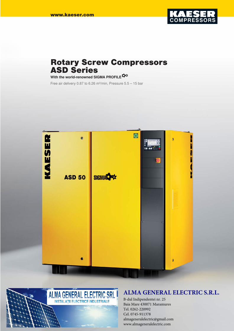
Image: ASD 50
Service-friendly design
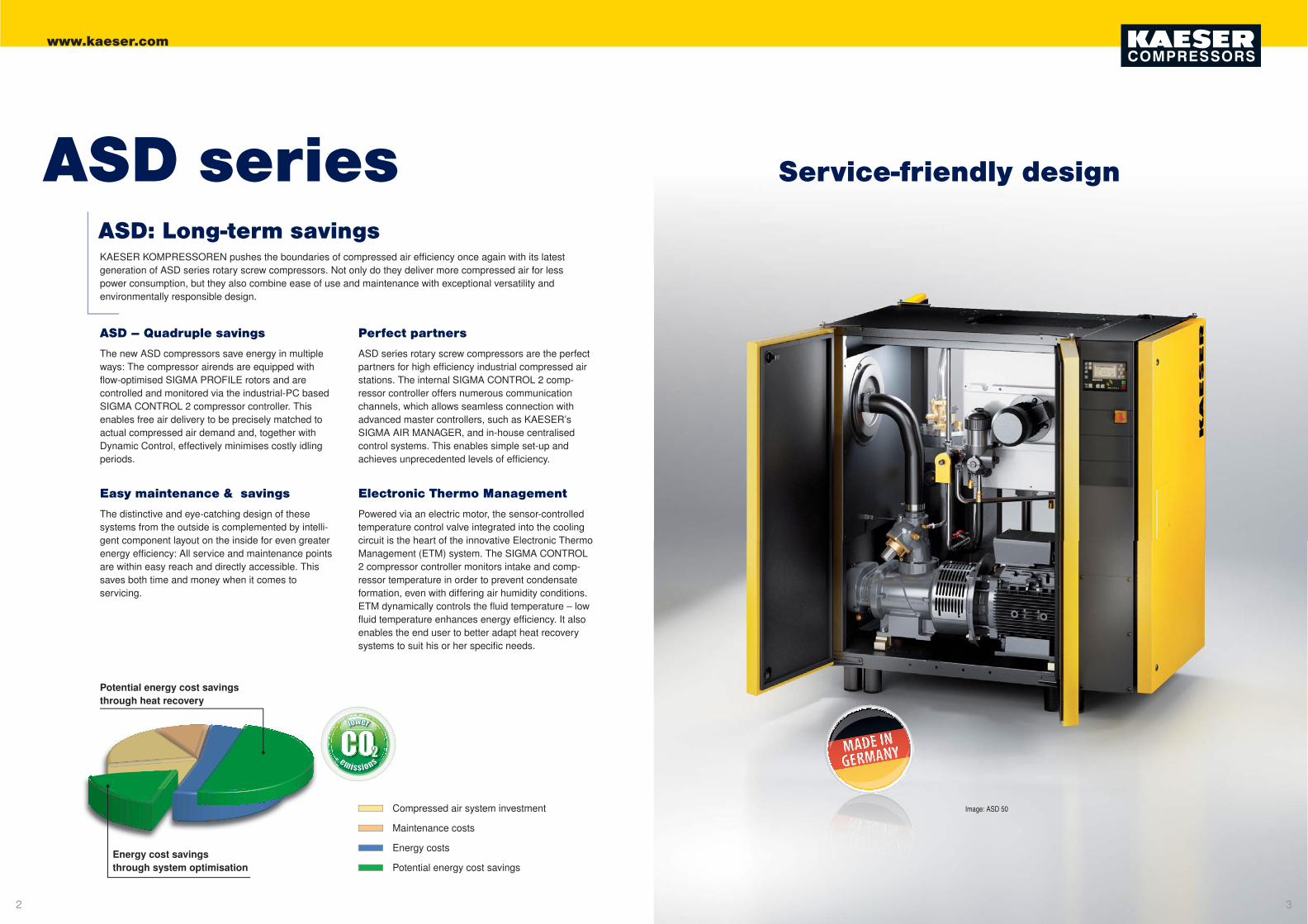
Compressed air system investment
Maintenance costs
Energy costs
Potential energy cost savings
Potential energy cost savingsthrough heat recovery
Energy cost savingsthrough system optimisation
KAESER KOMPRESSOREN pushes the boundaries of compressed air effi ciency once again with its latest generation of ASD series rotary screw compressors. Not only do they deliver more compressed air for less power consumption, but they also combine ease of use and maintenance with exceptional versatility andenvironmentally responsible design.
ASD – Quadruple savings
The new ASD compressors save energy in multiple ways: The compressor airends are equipped with fl ow-optimised SIGMA PROFILE rotors and arecontrolled and monitored via the industrial-PC basedSIGMA CONTROL 2 compressor controller. This enables free air delivery to be precisely matched to actual compressed air demand and, together with Dynamic Control, effectively minimises costly idling periods.
Easy maintenance & savings
The distinctive and eye-catching design of these systems from the outside is complemented by intelli-gent component layout on the inside for even greater energy effi ciency: All service and maintenance points are within easy reach and directly accessible. This saves both time and money when it comes toservicing.
Perfect partners
ASD series rotary screw compressors are the perfect partners for high effi ciency industrial compressed air stations. The internal SIGMA CONTROL 2 comp-ressor controller offers numerous communication channels, which allows seamless connection withadvanced master controllers, such as KAESER’s SIGMA AIR MANAGER, and in-house centralised control systems. This enables simple set-up and achieves unprecedented levels of effi ciency.
Electronic Thermo Management
Powered via an electric motor, the sensor-controlled temperature control valve integrated into the cooling circuit is the heart of the innovative Electronic Thermo Management (ETM) system. The SIGMA CONTROL 2 compressor controller monitors intake and comp-ressor temperature in order to prevent condensate formation, even with differing air humidity conditions. ETM dynamically controls the fl uid temperature – low fl uid temperature enhances energy effi ciency. It also enables the end user to better adapt heat recovery systems to suit his or her specifi c needs.

www.kaeser.com
1312
General designEquipment
Rotary screw airend with energy-saving SIGMA PROFILE rotors
Complete unit
Ready-to-run, fully automatic, super-silenced, vibration damped, all panels powder coated. Suitable for use in ambient temperatures up to +45°C.
Sound insulation
Panels lined with laminated mineral wool.
Vibration dampening
Double insulated anti-vibrationmountings using rubber bondedmetal elements.
Airend
Genuine KAESER rotary screw,single stage airend with energy-saving SIGMA PROFILE and cooling fl uid injection for optimised rotor cooling. Directly driven.
Drive
Direct, high-fl ex coupling, withoutgearing.
Electric motor
Premium effi ciency IE3 motor, qualityGerman manufacture, IP 55, ISO F for additional reserve; PT 100 winding temperature sensor for motor monitor-ing; externally lubricated bearings.
Electrical components
IP 54 control cabinet, control trans-former, Siemens frequency converter,fl oating contacts for ventilation control.
Fluid and air fl ow
Dry air fi lter; pneumatic inlet and vent-ing valve; cooling fl uid reservoir with triple separator system; pressure relief valve, minimum pressure check valve,
Heat recovery (HR)
Optionally available with integratedHR system (plate-type heatexchanger).
SIGMA CONTROL 2
“Traffi c light” LED indicators show operational status at a glance, plain text display, 30 selectable languages, soft-touch keys with icons, fully auto-mated monitoring and control. Selec-tion of Dual, Quadro, Vario, Dynamic and Continuous control as standard. Interfaces: Ethernet; additional optional communication modules for: Profi bus DP, Modbus, Profi net and Devicenet; SD card slot for data recording and updates; RFID reader, web server.
Electronic Thermo Management (ETM) and eco fl uid fi lter in the cooling fl uid circuit; fully piped connections, fl exible line connections.
Cooling
Air-cooled; separate aluminium cooler for compressed air and cooling fl uid; radial fan with separate electric motor, Electronic Thermo Management(ETM).
Refrigeration dryer
CFC-free, R134a refrigerant, fullyinsulated, hermetically sealed refriger-ant circuit, scroll refrigerant compres-sor with energy-saving shut-off feature, hot-gas bypass control, electronic con-densate drain and upstream centrifugal separator.
Standard version
Inlet fi lter
Inlet valve
Airend
Drive motor
Fluid separator
Aftercooler
KAESER centrifugal separator
Condensate drain(ECO-DRAIN)
Fluid cooler
Electronic Thermo Management
Fluid fi lter
Radial fan
T-SFC version
Inlet fi lter
Inlet valve
Airend
Drive motor
Fluid separator tank
Aftercooler
KAESER centrifugal separator
Condensate drain(ECO-DRAIN)
Fluid cooler
Electronic Thermo Management
Fluid fi lter
Radial fan
Integrated refrigeration dryer
Switching cabinet withintegrated SFC frequencyconverter
www.kaeser.com
1514
1.850
1.530
9001.540
1.530
900
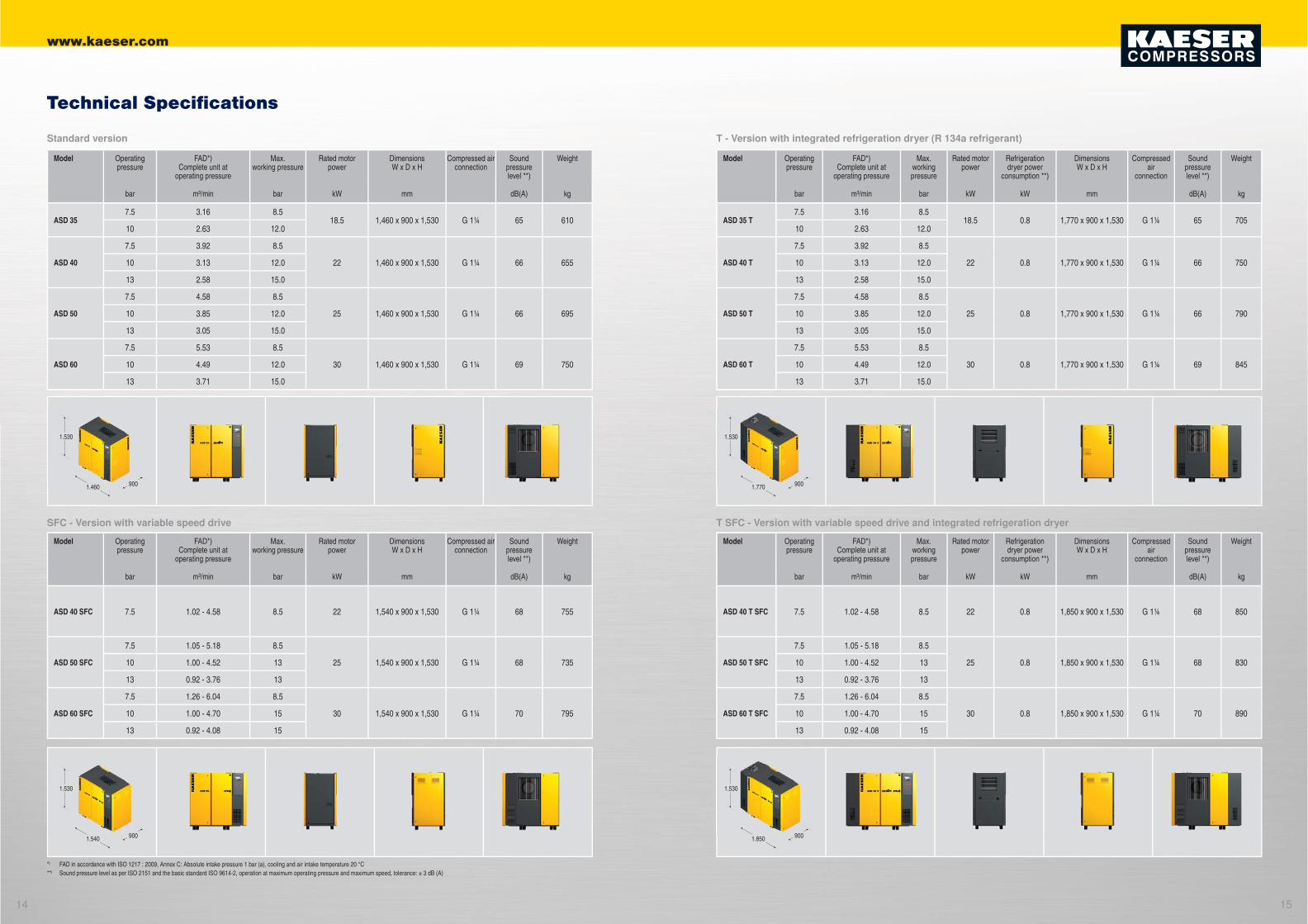
Modell Betriebs-überdruck
Liefermenge *) Gesamtanlage bei Betriebsüberdruck
max. Überdruck
Motornenn-leistung
Kältetrockner-leistungs-
aufnahme **)
AbmessungenB x T x H
Druckluft-anschluss
Schalldruck-pegel **)
Masse
bar m³/min bar kW kW mm dB(A) kg
ASD 35 T7.5 3.16 8.5
18.5 0.8 1,770 x 900 x 1,530 G 1¼ 65 70510 2.63 12.0
ASD 40 T
7.5 3.92 8.5
22 0.8 1,770 x 900 x 1,530 G 1¼ 66 75010 3.13 12.0
13 2.58 15.0
ASD 50 T
7.5 4.58 8.5
25 0.8 1,770 x 900 x 1,530 G 1¼ 66 79010 3.85 12.0
13 3.05 15.0
ASD 60 T
7.5 5.53 8.5
30 0.8 1,770 x 900 x 1,530 G 1¼ 69 84510 4.49 12.0
13 3.71 15.0
Modell Betriebs-überdruck
Liefermenge *) Gesamtanlage bei Betriebsüberdruck
max. Überdruck
Motornenn-leistung
Kältetrockner-leistungs-
aufnahme **)
AbmessungenB x T x H
Druckluft-anschluss
Schalldruck-pegel **)
Masse
bar m³/min bar kW kW mm dB(A) kg
ASD 40 T SFC 7.5 1.02 - 4.58 8.5 22 0.8 1,850 x 900 x 1,530 G 1¼ 68 850
ASD 50 T SFC
7.5 1.05 - 5.18 8.5
25 0.8 1,850 x 900 x 1,530 G 1¼ 68 83010 1.00 - 4.52 13
13 0.92 - 3.76 13
ASD 60 T SFC
7.5 1.26 - 6.04 8.5
30 0.8 1,850 x 900 x 1,530 G 1¼ 70 89010 1.00 - 4.70 15
13 0.92 - 4.08 15
Modell Betriebs-überdruck
Liefermenge *) Gesamtanlage bei Betriebsüberdruck
max. Überdruck
Motornenn-leistung
AbmessungenB x T x H
Druckluft-anschluss
Schalldruck-pegel **)
Masse
bar m³/min bar kW mm dB(A) kg
ASD 357.5 3.16 8.5
18.5 1,460 x 900 x 1,530 G 1¼ 65 61010 2.63 12.0
ASD 40
7.5 3.92 8.5
22 1,460 x 900 x 1,530 G 1¼ 66 65510 3.13 12.0
13 2.58 15.0
ASD 50
7.5 4.58 8.5
25 1,460 x 900 x 1,530 G 1¼ 66 69510 3.85 12.0
13 3.05 15.0
ASD 60
7.5 5.53 8.5
30 1,460 x 900 x 1,530 G 1¼ 69 75010 4.49 12.0
13 3.71 15.0
Modell Betriebs-überdruck
Liefermenge *) Gesamtanlage bei Betriebsüberdruck
max. Überdruck
Motornenn-leistung
AbmessungenB x T x H
Druckluft-anschluss
Schalldruck-pegel **)
Masse
bar m³/min bar kW mm dB(A) kg
ASD 40 SFC 7.5 1.02 - 4.58 8.5 22 1,540 x 900 x 1,530 G 1¼ 68 755
ASD 50 SFC
7.5 1.05 - 5.18 8.5
25 1,540 x 900 x 1,530 G 1¼ 68 73510 1.00 - 4.52 13
13 0.92 - 3.76 13
ASD 60 SFC
7.5 1.26 - 6.04 8.5
30 1,540 x 900 x 1,530 G 1¼ 70 79510 1.00 - 4.70 15
13 0.92 - 4.08 15
Technical Specifi cations
*) FAD in accordance with ISO 1217 : 2009, Annex C: Absolute intake pressure 1 bar (a), cooling and air intake temperature 20 °C**) Sound pressure level as per ISO 2151 and the basic standard ISO 9614-2, operation at maximum operating pressure and maximum speed, tolerance: ± 3 dB (A)
Standard version
SFC - Version with variable speed drive
T - Version with integrated refrigeration dryer (R 134a refrigerant)
T SFC - Version with variable speed drive and integrated refrigeration dryer
Model Operatingpressure
FAD*)Complete unit at
operating pressure
Max.working pressure
Rated motorpower
Refrigerationdryer power
consumption **)
DimensionsW x D x H
Compressed air
connection
Sound pressure level **)
Weight
bar m³/min bar kW kW mm dB(A) kg
ASD 35 T
ASD 40 T
ASD 50 T
ASD 60 T
Model Operatingpressure
FAD*)Complete unit at
operating pressure
Max.working pressure
Rated motorpower
Refrigerationdryer power
consumption **)
DimensionsW x D x H
Compressed air
connection
Soundpressurelevel **)
Weight
bar m³/min bar kW kW mm dB(A) kg
ASD 40 T SFC
ASD 50 T SFC
ASD 60 T SFC
Model Operatingpressure
FAD*)Complete unit at
operating pressure
Max.working pressure
Rated motorpower
DimensionsW x D x H
Compressed airconnection
Sound pressure level **)
Weight
bar m³/min bar kW mm dB(A) kg
ASD 35
ASD 40
ASD 50
ASD 60
Model Operatingpressure
FAD*)Complete unit at
operating pressure
Max.working pressure
Rated motorpower
DimensionsW x D x H
Compressed airconnection
Soundpressurelevel **)
Weight
bar m³/min bar kW mm dB(A) kg
ASD 40 SFC
ASD 50 SFC
ASD 60 SFC
1.770
1.530
9001.460
1.530
900