ROTARY SCREW AIR COMPRESSORS - Welcome to … manuals/2. Mini-screw Compressors/2... · STATEMENT...
54
COAIRE M-Series Microprocessor Control System MAINTENANCE MANUAL AND PARTS LIST MODELS : CHSA-7.5M CHSA-10M CHSA-15M CHSA-20M CHSA-25M CHSA-30M COAIRE TECHNOLOGIES, CORPORATION All rights reserved Printed in U.S.A. ROTARY SCREW AIR COMPRESSORS For proper and safe use of the compressor, please follow all instructions and safety precautions as identified in this manual, along with general safety regulations and practices.
Transcript of ROTARY SCREW AIR COMPRESSORS - Welcome to … manuals/2. Mini-screw Compressors/2... · STATEMENT...

COAIRE M-Series
Microprocessor Control System
MAINTENANCE MANUAL AND PARTS LIST
MODELS
CHSA-75M
CHSA-10M
CHSA-15M
CHSA-20M
CHSA-25M
CHSA-30M
COAIRE TECHNOLOGIES CORPORATION
All rights reserved Printed in USA
ROTARY SCREW AIR COMPRESSORS
For proper and safe use of the compressor please follow all instructions and safety precautions as identified in this manual along with general safety regulations and practices
SAFETY AND PRECAUTIONS Before you install the air compressor you should take the time to carefully read all the instructions contained in this manual Electricity and compressed air have the potential to cause severe personal injury or property damage Before installing wiring starting operating or making any adjustments identify the components of the air compressor using this manual as a guide The operator should use common sense and good working practices while operating and maintaining this unit Follow all procedures and piping accurately Understand the starting and stopping sequences Check the safety devices in accordance with the following procedures contained in this manual Maintenance should be done by qualified personnel accurately with proper tools Follow the maintenance schedule as outlined in the manual to ensure problem free operation after start up
SAFETY PRECAUTIONS BEFORE INSTALLING THE COMPRESSOR OR PERFORMING ANY MAINTENANCE READ THIS MANUAL
CAREFULLY
WARNINGS COMPRESSED AIR AND ELECTRICITY ARE DANGEROUS BEFORE DOING ANY WORK ON THIS UNIT BE SURE THE
ELECTRICAL SUPPLY HAS BEEN SHUT OFF(LOCKED AND TAGGED) AND THE ENTIRE COMPRESSOR SYSTEM HAS
BEEN VENTED OF ALL PRESSURE
1 Do not remove the cover loosen or remove any fittings connections or devices when this unit is operating or in
operation Hot liquid and air that are contained within this unit under pressure can cause severe injury or death 2 The compressor has high and dangerous voltage in the motor the starter and control box All installations must be in
accordance with recognized electrical procedure Before working on the electrical system ensure that the systems power has been shut off by use of a manual disconnect switch A circuit breaker or fuse switch must be provided in the electrical supply line to be connected to the compressor The preparation work for installation of this unit must be done in suitable grounds maintenance clearance and lighting arrestors for all electrical components
3 Do not operate the compressor at a higher discharge pressure than those specified on the compressor nameplate If so an overload will occur This condition will result in electric motor compressor shutdown
4 Use only safety solvent for cleaning the compressor and auxiliary equipment 5 Install a manual shut off valve(isolation type) in the discharge line for service work 6 Whenever pressure is released through the safety valve during operation it is due to excessive pressure in the
system The cause of excessive pressure should be checked and immediately corrected 7 Before doing any mechanical work on the compressor a) Shut down the unit b) Electrically isolate the compressor by use of the manual disconnect switch in the power line to the unit Lock and
tag the switch so that it cannot be operated c) Release all compressed air within the system and isolate the unit from any other sources of air 8 Allowing the unit lubricants to enter into the plant air system must be avoided at all times Air line separators which
are properly selected and installed can reduce any liquid carry-over close to zero 9 Before starting the compressor the maintenance instructions should be thoroughly read and understood 10 After maintenance work is completed covers must be securely closed 11 For questions contact your distributor before proceeding
STATEMENT OF WARRANTY TERMS amp CONDITIONS COAIRErsquos screw air compressors are warranted to be free of defects in materials and workmanship under proper use installation and application This warranty shall be for a period of 15 months from date of shipment from our factory or other stocking facilities or 12 months from date of installation Proof of installation date will be required All air compressors outside the US and Canada carry a parts only warranty ALL FREIGHT DAMAGE CLAIMS ARE NOT THE RESPONSIBILITY OF THE MANUFACTURER AND ARE NOT COVERED UNDER WARRANTY AS ALL PRODUCTS ARE SHIPPED FOB SHIPPER
PLEASE DIRECT ALL FREIGHT CLAIMS TO THE SHIPPER IN QUESTION
MAINTENANCE AND ADJUSTMENTS
ADJUSTMENTS PRESSURE SETTINGS AND MAINTENANCE OF FLOAT AND AUTOMATIC DRAINS AND OIL COOLER COILS ARE CONSIDERED TO BE ROUTINE MAINTENANCE AND THEREFORE NON-WARRANTABLE ITEMS AND ARE THE SOLE RESPONSIBILITY OF THE END USER CONSULT THE INSTALLATION OPERATION AND MAINTENANCE MANUAL FOR THE ADJUSTMENT AND MAINTENANCE PROCEDURES
This warranty does not apply to any unit damaged by accident modification misuse negligence or misapplication Damage to heat exchangers by exposure to ammonia any other corrosive substance or sub-freezing environment will be considered misuse
Any air compressors part or material found defective will be repaired replaced or refunded at the sellers option free of charge provided that COAIRE is notified within the above stated warranty period All returns of allegedly defective equipment must have prior written authorization Said authorization may be obtained through our air compressor service department All air compressors parts materials must be returned freight prepaid to the Manufacturerrsquos factory within 30 days of return authorization date Any shipment returned to the factory collect will be refused
If an item is found to be warrantable the repaired item or replacement will be returned normal ground freight prepaid within the continental United States and Canada Expedited shipment costs are the responsibility of the requestor
Any replacement part or material is warranted only to the extent of the remaining warranty period of the air compressor or to the extent as provided by the supplier whichever is longer
Identification Plate The identification plate is located on the side of the air compressor and shows all the primary data of the machine Upon installation fill in the table on the previous page with all the data shown on the identification plate This data should always be referred to when calling the manufacturer or distributor The removal or alteration of the identification plate will void the warranty rights
DISCLAIMER The warranty does not cover any responsibility or liability for direct or indirect damages to persons or equipment caused by improper usage or maintenance and is limited to manufacturing defects only Refer to COAIRE Warranty policy manual for travel mileage and special charge considerations The warranty will be immediately voided if there are changes or alterations to the air compressor
WHO TO CONTACT IF YOU HAVE A WARRANTY CLAIM COAIRE Technologies Corporation Phone (562) 463-3935
Fax (562) 463-4928
All freight damage claims should be filed within 15 working days and should be directed to the carrier
TABLE OF CONTENTS
Chapter Ⅰ General information
1-1 Instruction 1
1-2 Screw compression process 1
1-3 Compressed air flow 2
1-4 Cooling air flow 2
1-5 Oil separation 2
1-6 Oil flow 2
1-7 Oil scavenge flow 2
1-8 Standard Specifications 3
1-9 Installation and wiring 4
Chapter Ⅱ Operating instructions
2-1 Operating panel 8
2-2 Initial start-up 9
2-3 Daily operation 10
2-4 Standard factory settings of control components 11
2-5 Operation and control sequence 12
2-6 Microprocessor Controller 14
Chapter Ⅲ Functional Description
3-1 Compressor air-end 19
3-2 Drive motor 20
3-3 V-Belt drive 20
3-4 Capacity control 20
3-5 Lubrication system 20
3-6 After cooleroil cooler 20
3-7 Oil separator 20
3-8 Oil Filter 20
3-9 Thermostatic Valve 20
3-10 Min Pressure Valve 20
3-11 Air Intake Filter 20
3-12 Instrument Panel 21
3-13 Starter and control box 21
3-14 Safety device 21
Chapter Ⅳ Scheduled Maintenance
4-1 Standard maintenance schedule 22
4-2 Control of lubrication 23
Chapter Ⅴ Trouble shooting
5-1 Trouble symptoms and solutions 25
5-2 Operation record form 26
Chapter Ⅵ Corrective maintenance
6-1 Oil filter 28
6-2 Suction filter 29
6-3 Oil separator element 29
6-4 Oil seal 29
6-5 Min Pressure valve 30
6-6 Suction control valve 30
6-7 Cooling fan 30
6-8 Oil temperature regulating valve 30
6-9 V-Belt 31
6-10 Pressure transmitter 32
6-11 Safety valve 32
Appendix
A Compressor Part List 33
B Parts List 36
C PC Board 44
D Wiring Diagram 45
E Outline Drawing 47
1
CHAPTER I
GENERAL INFORMATION 1-1 INSTRUCTION COAIRE screw air compressor unit is a complete package type driven by an electric motor It is single stage oil injected rotary screw type with all components full piped wired and mounted on a common base it is a very self-contained air compressor package
1-2 SCREW COMPRESSION PROCESS
1-2-1 SUCTION PROCESS Along with the rotation of the rotor air is admitted fully into the void of two rotors through the suction port The void is then isolated from the suction port with the casing wall thereby completing the suction process
Fig 1-1 Suction Process
1-2-2 COMPRESSION PROCESS The air in the void is compressed as the male rotor lobe meshes between the female rotor lobes and squeezes the air against discharge cover
Fig 1-2 Compression Process
1-2-3 OIL INJECTION PROCESS As pressure builds oil is injected into the compression area and onto the bearings and shaft seal serving to lubricate absorb compression heat and seal the rotors
Fig 1-3 Oil Injection Process
1-2-4 DISCHARGE PROCESS Compression continues as the rotor rotates When the void comes to the discharge port provided in the discharge chamber the compressed air is discharged through the port While this process is occurring with one inter-lobe space the other spaces are following the same cycle Therefore air is compressed continuously
Fig 1-4 Discharge Process
2
1-3 COMPRESSED AIR FLOW The panel has an intake duct through which air is drawn into the enclosure Airflows through an air intake filter intake silencer and suction control valve to the air-end suction port Air then is compressed by the rotation of the male rotor and oil is injected into the air-end during compression process The injected oil performs various functions such as sealing cooling as well as lubricating The airoil mixture leaves the air-end through the discharge port and flows into the oil separator where the oil is separated from the compressed air Compressed air leaves the oil separator and is supplied to discharge connection of the unit via minimum pressure valve after-cooler and liquid separator
1-4 COOLING AIR FLOW The air-cooled unit comprises a forced ventilation system with a cooling fan which is driven by an electric motor First the cooling air removes the heat generated from the main motor air end etc The cooling air is then forced into the oil and after-cooler by cooling fan After the heat exchange the hot air flows through the ventilation duct and is exhausted from the ventilation louvers in the panel
1-5 OIL SEPARATION Primary separation Most of the oil is separated from air by the impact at the inner wall of the oil separator and by the fluid cyclonic effect After primary separation the heavy oil falls and is collected in the oil sump at the bottom of the oil separator Secondary separation The air which still contains fine oil particles flows through the oil separator element where the oil forms into large particles and is collected at the bottom of the element shell Then clean air leaves the oil separator 1-6 OIL FLOW The oil which is collected in the oil sump at the bottom of the oil separator is circulated through the lubrication system by the pressure differential existing between the oil separator and the air-end The oil temperature control valve is a bypass valve When the oil is cold the oil bypasses the oil cooler partly or completely and is sent to the oil filter When the oil is hot 185 lsquoF(85rsquoC) or more the oil flows into the oil cooler unless by-pass the compression chamber and lubrication parts of the air-end Oil injected via the internal oil hole is provided into the intermesh among male rotor female rotor and the rotor casing the shaft seal suction side and discharge side bearings 1-7 OIL SCAVENGE FLOW After oil is separated from the air and collected in the element shell of the oil separator it is scavenged to the compression chamber of the air-end by the internal pressure differential so that the oil carry-over in the discharged air can be controlled within the allowable limit
3
M
TS PI
PT
Fig 1-5 Operating flow diagram
1-8 STANDARD SPECIFICATIONS MODEL
ITEM CHSA-75M CHSA-10M CHSA-15M
Motor output Kw(HP) 55(75) 75(10) 11(15) Discharge pressure psi(g) 110 125 150 110 125 150 110 125 150 Air delivery cfm 290 265 230 385 360 310 570 520 460 Compressor speed RPM 5250 4720 4350 6950 6380 5950 6450 6200 5550 Oil flow rate gpm 40 53 80 Ambient temperature 32 115sim Discharge air temperature Inlet air temperature + 27 (MAX) Driving method - V-Belt V-Belt Voltage V 3Ph(1Ph) 208-230V 3Ph 208-230460V Frequency Hz 60 Starting method - Direct on Start Oil sump capacity gal 07 07 11 Noise level dB(A) 68 70 71 Weight lbs 300 310 420 Dimensions(WtimesDtimesH) in 17times2458x3258 2834x4138x4218 Air outlet piping size in 34rdquo 1rdquo
Air
Cleaner
Solenoid
Valve
Only
15 ~ 30HP
Oil Filter
Oil Cooler
Thermostat
Valve
Oil
Separator
Min
Pressure
After Cooler
Oil Separator
Tank
Symbol PT Pressure Transmitter
TS Temperature Sensor
PI Pressure Indicator
M Motor
4
MODEL
ITEM CHSA-20M CHSA-25M CHSA-30M
Motor output Kw(HP) 15(20) 19(20) 22(30) Discharge pressure psi(g) 110 125 150 110 125 150 110 125 150 Air delivery cfm 734 680 640 1253 1150 1080 Compressor speed RPM 8280 7900 7500 5700 5380 5160 Oil flow rate gpm 85 119 119 Ambient temperature 32 115sim Discharge air temperature Inlet air temperature + 27 (MAX) Driving method - V-Belt V-Belt Voltage V 3Ph 208-230 460 Frequency Hz 60 Starting method - Direct on Start Oil sump capacity gal 11 13 13 Noise level dB(A) 72 73 73 Weight lbs 450 550 630 Dimensions(WtimesDtimesH) in 2834x4138x4218 3112x4714x4978 Air outlet piping size in 1rdquo 1rdquo
1-9 INSTALLATION AND WIRING Upon delivery carefully check the air compressor unit(s) for damage during transportation 1-9-1 HANDLING When handling by a forklift make sure that forks completely extend through the width of the unit When handling by a shop crane use the openings provided on common base where slings or steel wire ropes can be use for lifting
Fig 1-6 Handling by forklift truck
Fig 1-7 Handling by shop crane
1-9-2 LOCATION The unit should be installed in a dry well ventilated area dust-free environment The unit should not be installed outdoors Consideration must be given to the need for clearance around the unit to avoid the re-circulation of air-end for easy maintenance access
5
(Unit Inch)
Fig 1-8 The space clearance example
CAUTION
- Install the unit in a dust-free room of low humidity and on a level concrete floor
- Never install the unit on timbers or block High humidity may result in electrical shorts and corrosion
- Dust particles containing iron or sand may result in poor resistance of the motor and air-end damage
- A ventilation fan should be provided to keep the ambient temperature 115 or lower
- operation at ambient temperature of higher than 115 may cause compressor shutdown or severe
damage to the unit
HEAT GENERATION amp VENTILATION FAN CAPACITY MODEL
CAPACITY CHSA-75M CHSA-10M CHSA-15M CHSA-20M CHSA-25M CHSA-30M
CAPACITY (Btuh) AIR VOLUME (cfm) 1165 1235 1900 2120 2330 2540 Note 1 The room ventilation capacity is based on (1) Compressor room Temperature rise which is controlled within the 9 (2) Static pressure of ventilation air should be 0 inchWG 2 Consult the distributor for more information on ventilation capacity when the air exhaust duct is installed
A B C D CHSA-75M 24 42 42 24 CHSA-10M 24 42 42 24 CHSA-15M 24 42 42 24 CHSA-20M 42 42 42 24 CHSA-25M 24 42 42 24 CHSA-30M 24 42 42 24
6
1-9-3 PIPING WORK
CAUTION
- All service piping must be installed so as to exert zero force of movement on the system
- A drain valve and isolation valve should be mounted near the compressor discharge section
- Water condensation can affect the operation of pneumatic devices After-coolers and the addition of
air dryers can eliminate this hazard Similarly avoid allowing compressor coolant to enter the plant air
systems Air line separators properly selected and installed will reduce any liquid carry-over
- When installed in parallel operation you must provide an isolation valve and drain trap for each
compressor unit before the common receiver Screw air compressors should not be installed in air
systems with reciprocating compressors without a means of isolation such as a common receiver It
is recommend that both types of compressor units are piped to a common receiver utilizing individual
air lines
- In case of a lead fluctuation or a very small volume in pipe from discharge connection of compressor
unit to the end of the piping the use of air receiver is recommended
- In case the discharge piping has to be unusually long you should select the diameter of the piping in
considering the pressure drop in the piping
- Consult your distributor for proper technical support
Fig 1-9 Parallel installation Fig 1-10 Installation with reciprocating compressor
1-9-4 ELECTRICITY This extensive line of Coaire screw air compressors has been designed to provided all the conveniences of air supply system especially for the stats of the art manufacturing industries These units are composed of compressor motor protection devices and control equipment The applicable voltage range for each unit is given in the electrical data The working voltage among the three phases must be balanced within 2 deviation from each voltage at the compressor terminals Voltage range limit is to be 90~110 of regular voltage described in proportional frequency Unbalance of voltage measured in motor terminals should be within 3 in accordance with the following formula
(V)max - (V)mean ---------------------------- times 100 () (V)mean where (V)max Maximum voltage among three terminals (V)mean Average voltage among three terminals
CAUTION
7
ELECTRICAL WIRING
- Read all related topics in this manual
- Comply to the National Electric Code(NEC) and any other local codes
- Utilize a qualified licensed electrical contractor
1-9-5 ELECTRICAL SPECIFICATION
3 Phase Motor
MODEL
AIR-END MOTOR NO FUSE
BREAKER
OVER
CURRENT
RELAY
MAIN CABLE
OUTPUT
[kWHp]
INPUT
[kW]
POWER[V]
3oslash60Hz
FLA
[A]
LRA[A] POWER
FACTOR
[]
FRAME
[AF]
TRIP
[A]
TRIP
[A]
POWER
[]
KIV
GROUND
[]
GV DIRECT Y-DELTA
CHSA-75M 55975 208 190 708 -
94
230 170 640 - 460 85 320 -
CHSA-10M 74610 208 256 741 -
91
230 232 670 - 460 116 385 -
CHSA-15M 111915 208 387 1371 -
90
230 350 1240 - 460 175 620 -
CHSA-20M 149220
208 520 1680 -
88
230 470 1520 -
460 235 760 -
8
CHAPTER II
OPERATING INSTRUCTIONS
2-1 OPERATING PANEL The schematic figure and the names of each part in the operating panel are as follows
Fig 2-1 Operating panel
DESCRIPTION FUNCTION Start Switch for Running Stop Switch for stopping Pressure Indicates the discharge pressure Temperature Indicates the discharge temperature Run Signal lamp for running Alarm Signal lamp for alarm ResetEnter Switch for the alarm reset and input value Menu Switch for selecting the message on the LCD screen Up Switch for increasing the input value Down Switch for decreasing the input value Hour Indicates the running time
ENTERDOWN UP
RUN
PRESSURE(kgcm )
MENU
ALARM
M
HOUR
H
STOP
TEMPERATURE(degC)
START
RESET
2
9
2-2 INITIAL START-UP Before starting the unit for the first time all operators must become familiar with all parts and assemblies Only qualified personnel are to start the machine(Contact your distributor)
2-2-1 BEFORE OPERATION Make sure that
All installation piping and electrical work has been properly installed and completed The main power is disconnected The voltage of the power source is at a regular level Tightness of all electrical connections and wirings Tightness of all joints fasteners covers plugs and caps are inspected Tightness of all grounding connections are inspected V -belt tensions are inspected The oil level is a t the proper point Isolation stop valve in the discharge air line is completely open
WARNING
CHECK PROPER ROTATION
There is no the reverse phase relay in the unit Operator should open the front belt guard and
check proper rotation visually You can see rotation arrow on the belt guard Reinstall guard
prior to any further running 2-2-2 STARTING
Turn on the main disconnection switch Power lamp on air compressor instrument panel lights up
Press start key on operating panel of the uni t The running lamp on the unit-operating panel lights up
Check the rotation While checking proper rotation you should not run the machine for 5 sec or more If you do not the air-end will be damaged Reinstall guard prior to any further operation
WARNING
REVERSE ROTATION
Upon initial operation check proper rotation If reverse rotation disconnect the main power
and interchange two of three main cables on terminal board installed in the control box Check oil level and run the unit for a short period Oil level may drop as
oil circulates into the system Add oil if the level during operation should be below the lower centerline of lower oil level gauge Press stop button to stop the motor After confirming that the discharge pressure gauge reads 0 psig(approximately 90 seconds after stopping the motor) add oil as necessary
Check the unit for any abnormal noise or vibration Run the unit at the discharge pressure 57 to 71 psig for approximately one hour gradually close the isolation stop valve until the discharge pressure gauge
indicates the same pressure as the oil sump pressure
WARNING
10
Do not loosen the oil-filling plug before the internal pressure is vented completely Make sure
that the oil-filling plug is tightly fastened after oil has been added Restart the unit Check the
oil piping for any oil leak and correct as required
Check the safety valve Pull the attached ring to operate the safety valve use caution and appropriate
safety equipment Check the capacity control system Gradually close the stop valve at the external air receiver As discharge
pressure rises stop closing when the discharge pressure reaches the cutout pressure 2-2-3 STOPPING
Press STOP key Machine is stopped after 30 second stop control time Make sure that the blow -off solenoid valve operates
The blow-off air sounds for approximately 90 seconds Make sure that the discharge pressure gauge reads 0 psig
2-3 DAILY OPERATION
BEFORE EACH DAY OF OPERATION Drain the condensation from after-cooler
Check oil level Proper oil level is at centerline of upper oil level gage w ith machine not running STARTING Press START key
DURING THE OPERATION Check oil level gauge Make sure that all gauges in compressor instrument panel indicates normal status and followings
SPECIFICATION UNIT Limit Remarks Discharge temperature Less Than 203 Ambient Temperature Less Than 115 Indicating Lamps - Run Voltage Volt Normal Power plusmn10 Current Amp Less than Normal Current+15 Pressure Differential unit and line PSID Max 15
STOPPING
Press STOP key Make sure that th e discharge pressure gauge reads 0 psig Operate the toggle switch for oil heater as follows(if option is installed)
For ambient temperature consistently over 50 when the unit is idled place the toggle switch to OFF position For ambient temperature consistently below 50 when unit is not running place the toggle switch to ON position
2-4 STANDARD FACTORY SETTINGS OF CONTROL COMPONENTS SPECIFICATION UNIT STANDARD FACTORY SETTING VALVE
Discharge pressure Psi 110 125 150 Minimum pressure valve Psi 57 Discharge pressure switch Psi 11090 125105 150130 Oil separator element diff switch Psi 10 Oil filter diff switch Psi 25 Discharge temperature switch 220
11
2-5 OPERATION AND CONTROL SEQUENCE (1) CAPACITY CONTROL SYSTEM
POWER ON
rarr
darr
(Check rotation) START
darr (No alarm) darr larr
POWER OFF
IF REVERSE
ROTATION
Y-Δ START
(IF APPLICABLE DELTA RUN
AFTER Y-START)
uarr
darr
EXCHANGE 3
OF 2 MAIN
CABLE
LOAD OPERATION
(AFTER 5 SEC IDLING
OPERATION)
rarr larr
larr darr darr
LINE PRESSURE MONITORING
(PRESSURE SWITCH)
SET PRESSURE
OR LESS LOAD OPERATION
(Loading Valve ON)
uarr
SET PRESSURE OR MORE
uarr
OFF LOAD OPERATION
(Loading Valve OFF)
darr
uarr
LINE PRESSURE MONITORING
(Pressure Transmitter)
SET PRESSURE
OR MORE OFF LOAD
OPERATION
(Loading Valve OFF)
SET PRESSURE MINUS 21
PSIG
darr
RETURN LOAD OPERATION
(Loading Valve ON)
OFF LOADING TIME
CHECK
uarr darr darr
STAND-BYMODE
(AFTER STOPPING
OPERATION)
AUTO-RESTART
BY LINE PRESSURE
darr
12
(2) STOP CONTROL SYSTEM
WHILE
MACHINE IS
RUNNING
darr PUSH STOP BUTTON darr
MONITORING WHEN IN OFF-LOAD
OPERATION
WHEN IN
LOAD
OPERATION darr rarr darr
OFF-LOAD OPERATION
OFF-LOAD OPERATION TIME COUNT
(IF SET TIME IS OVER) darr (IF SET TIME IS ON)
STOP CONTROL
OPERATION
WHILE SET TIME
(SET TIME30~60SEC)
darrOFF-LOAD OPERATION
WHILE REMINING TIME
darr darr larr MACHINE STOP
(3) TROUBLE MONITORING SYSTEM
MOTOR OVERLOAD HIGH DISCHARGE
TEMPERATURE
OIL FILTER or
OIL SEPARATOR
CLOGGED
OCR(ITH) TEMPERATURE SENSOR DIFF PRESSURE
SWITCH
FLASH ALARM LAMP ON SWITCH PANEL
ALARM MESSAGE ON LCD
BUZZER
RESET AND STOP DISCONNECT POWER AND RELEASE PRESSURE
CHECK AND REPLACE
RESTART
13
2-6 MICROPROCESSOR CONTROLLER 2-6-1 ALARM MESSAGE
DISPLAY DISCRIPTION COP ocr Indicates the COMPRESSOR MOTOR OVERLOAD Fan ocr Indicates the COOLING FAN MOTOR OVERLOAD OIL FLt Indicates the OIL FILTER CLOGGED OIL SPt Indicates the OIL SEPARATOR CLOGGED OHt HI Indicates the HIGH DISCHARGE TEMPERATURE SEn Err Indicates the TEMPERATURE SENSOR ABNORMAL Pt Err Indicates the PRESSURE TRANSMITTER ABNORMAL PrS HI Indicates the ABNORMAL DISCHARGE PRESSURE
2-6-2 SET VALUE CHANGING MENUS Various data values showing the running status of the unit can set or display
Y-DELTA START
SET TIME XX [SEC] Displays the Y-Delta delay time (Applicable to Y-Delta units only)
IDELING START
SET TIME XX [SEC] Displays the idling delay time
UNLOADING CONTROL
SET TIME XX [MIN] Displays the idling delay time
STOP CONTROL
SET TIME XX [SEC] Displays the stop control time
DISCHARGE AIR
SET TEMP XXX [] Displays the discharge temperature
DISCHARGE PRESS
SET XXX [PSI] Displays the discharge air pressure
DRAIN ON-TIME
SET XX [SEC] Displays the auto drain valve on-time(open)
DRAIN OFF-TIME
SET XX [MIN] Displays the auto drain valve off-time(close)
MACHINE TYPE
MINI SCREW or RECIPROCATING Displays the current set machine type
UNITS CHANGE
METRIC LBS Displays the current set units
14
2-6-3 CHANGING SET VALUES It is highly recommended that the following procedures be conducted by qualified factory trained personnel Consult your distributor The running mode of the unit is programmed upon delivery However the operator may amend it depending on conditions and needs To amend the set value operator has to release the system key lock first Mode selection may be reset in the following way HOW TO RELEASE SYSTEM KEY LOCK
Press [MENU] key one time Machine will ask the operatorrsquos password and following message will be appeared ldquoPSd ldquo letter will light on and last three digits will flash to input password step by step On the screen
TEMPERATURE
PSd - - -
Make password of 111 by using the arrow keys and press enter key When password input the screen to be
amend is to be display Once the password is installed it lasts for about 5 minutes CAUTION The operatorrsquos password is 111
2-6-3-1 CHANGING THE PASSWORD 1) Release the system key lock 2) Press [MENU] key two times Following message will appear And ldquoPSd - - -ldquo will flash to input password step by step On the screen
TEMPERATURE
PSd - - -
Make new password by using the arrow keys and press enter key Password should be three digits numeric only
2-6-3-2 CHANGING THE WORKING PRESSURE 1) Release the system key lock 2) Press [MENU] key Three times The working pressure can be amended after releasing the engineerrsquos password The engineeringrsquos password is used at factory only
PRESSURE
X X X
3) Amend the set value by using (Up) and (Down) Keys Input the set value at flashing digit by using the arrow keys and press enter key Flashed digit will be moved next digit automatically Press (Up) Key to increase the set point Increases are displayed in 1(one) PSI increments Press (Down) Key to decrease the set point Decreases are displayed in 1(one) PSI decrements
15
2-6-3-3 CHANGING THE DISCHARGE ALARM TEMPERATURE 1) Release the system key lock 2) Press [MENU] key four times On the following screen last digit will be flashed to be able to input valve
TEMPERATURE
X X X
3) Amend the set value by using (Up) and (Down) Keys Input the set value at flashing digit by using the arrow keys and press enter key Flashed digit will be moved next digit automatically
Press (Up) Key to increase the set point Increases are displayed in 1(one) lsquoF increments Press (Down) Key to decrease the set point Decreases are displayed in 1(one) lsquoF decrements 2-6-3-4 CHANGING THE IDLING START TIME 1) Release the system key lock 2) Press [MENU] key five times On the following screen last digit will be flashing to be able to input valve
TEMPERATURE
Idl 000
3) Amend the set value by using (Up) and (Down) Keys Input the set value at flashing digit by using the arrow keys and press enter key Flashed digit will be moved next digit automatically
Press (Up) Key to increase the set point Increases are displayed in 1(one) second increments Press (Down) Key to decrease the set point Decreases are displayed in 1(one) second decrements
2-6-3-5 CHANGING THE UNLOADING CONTROL TIME 1) Release the system key lock 2) Press [MENU] key six times On the following screen last digit will be flashing to be able to input valve
TEMPERATURE
Uld 000
3) Amend the set value by using (Up) and (Down) Keys Input the set value at flashing digit by using the arrow keys and press enter key Flashed digit will be moved next digit automatically
Press (Up) Key to increase the set point Increases are displayed in 1(one) minute increments Press (Down) Key to decrease the set point Decreases are displayed in 1(one) minute decrements
16
2-5-3-6 CHANGING THE STOP CONTROL TIME 1) Release the system key lock 2) Press [MENU] key seven times On the following screen last digit will be flashing to be able to input valve
TEMPERATURE
StP 000
3) Amend the set value by using (Up) and (Down) Keys Input the set value at flashing digit by using the arrow keys and press enter key Flashed digit will be moved to the next digit automatically
Press (Up) Key to increase the set point Increases are displayed in 1(one) second increments Press (Down) Key to decrease the set point Decreases are displayed in 1(one) second decrements
2-6-3-7 CHANGING THE DRAIN VALVE OFF-TIME(CLOSE TIME)
1) Release the system key lock 2) Press [MENU] key eight times On the following screen last digit will flash to be able to input value
TEMPERATURE
Drn F00
3) Amend the set value by using (Up) and (Down) Keys Input the set value at flashing digit by using the arrow keys and press enter key Flashed digit will be moved to the next digit automatically Press (Up) Key to increase the set point Increases are displayed in 1(one) minute increments Press
(Down) Key to decrease the set point Decreases are displayed in 1(one) minute decrements 2-6-3-8 CHANGING THE DRAIN VALVE ON-TIME(OPEN TIME)
1) Release the system key lock 2) Press [MENU] key nine times On the following screen last digit will flash to be able to input valve
TEMPERATURE
Drn o-0
3) Amend the set value by using (Up) and (Down) Keys Input the set value at flashing digit by using the arrow keys and press enter key Flashed digit will be moved to the next digit automatically Press (Up) Key to increase the set point Increases are displayed in 1(one) second increments Press
(Down) Key to decrease the set point Decreases are displayed in 1(one) second decrements 2-6-3-9 Factory Set Values No Items Factory set point Adjustable Range 1 Compressor discharge shut down temperature 220 176 ~ 230 2 Start idling time 5 Sec 5 ~ 10 Sec 3 Unloading control time 5 Min 5 ~ 10 Min 4 Stop control time 30 Sec 20 ~ 50 Sec 5 Drain valve off-time 5 Min 1 ~ 45 Min 6 Drain valve on-time 1 sec 1 ~ 5 Sec 7 Discharge pressure 110 Psi 80 ~ 190 PSI
17
2-6-3-10 DIP SWITCH
No Items FUNCTION
Items ON OFF 1 MACHINE M-screw Scrolloil-less
2 PU Pressure switch By-pass Oil-less type only for capacity control
3 REMOTE Remote Non-remote 4 AUTO RESTORE Auto restart Manual restart After restoring power 5 UNITS Metric units Lbs-inch UNITS
18
CHAPTER III
FUNCTIONAL DESCRIPTIONS
3-1 COMPRESSOR AIREND Oil injected single stage rotary screw type that primarily consists of rotors housing and shaft seal along with other component parts Features Precision grind rotors provide close inter-lobe clearance This minimizes leakage and increases efficiency
Long service life and high reliability of bearings achieved by application of 5+7 profile rotors At the discharge end of the compressor angular contact ball bearings for the male and female rotors are located to support axial thrust loads and to position the rotor Cylindrical roller bearings are also located to support radial loads
With a differential pressure lubrication system the compress or can dispense with an oil pump thus dramatically simplifying the oil supply system
The wedge construction of the secondary sealing element of the mechanical seal naturally eliminates leakage This seal is highly reliable and excellent performance
3-1-1 ROTORS The male rotor has five lobes and the female rotor has seven grooves This is patented SRM designed profiles
Fig 3-2 Pair of rotor
3-1-2 HOUSING The cylindrical roller bearings support the radial loads whereas the angular ball bearings support the axial loads
3-1-3 SHAFT SEAL Mechanical seal is fitted on the male rotor shaft to prevent oil leakage
Fig 3-3 Detail of mechanical seal
3-2 DRIVE MOTOR IEC or NEMA standard drip-proof 3-phase 2 or 4 pole induction motor
19
3-3 V-BELT DRIVE Motor speed is increased by V-belt drive to the male rotors driving speed
Fig 3-4 V-Belt drive
3-4 CAPACITY CONTROL All models provide capacity control on-lineoff-line control Internal pressure is vented to atmosphere at partially loaded or unload conditions whereby the motor idles for power saving features 3-5 LUBRICATION SYSTEM The lubrication system consists of oil cooler oil separator and controls the oil temperature within an allowable limit The oil circulates through the system by differential pressure
3-6 AFTER COOLER OIL COOLER The cooler assembly is consisting in heat exchanger cooling fan fan motor and bracket After-cooler and oil-cooler are composed of corrugated fin and tube type with aluminum material Those fins remove the compression heat efficiently Cooling fan exhausts the heat-exchanged air through a ventilation duct to the outside of the enclosure 3-7 OIL SEPARATOR Spin-on type Oil separator is located at the air-end which efficiently separates the oil from discharged air 3-8 OIL FILTER Oil filter element is located at the air-end which efficiently filtering foreign material from circulating oil The oil filter has from 5 to 10 micron paper cartridge and it should be replaced every 1000 run hours normally 3-9 THERMOSTATIC VALVE This is the oil by-pass valve Located in the oil cooler outlet pipe in order to maintain adequate system temperature for efficient compression and protect to making water from compressed air The operating temperature is set 160
3-10 MINIMUM PRESSURE VALVE Located in air-end discharge in order to maintain adequate system pressure for efficient separation of oil pressure setting is 57 psig If less than 57 psig adjust the screw to maintain pressure on 57 psig or more
3-11 AIR INTAKE FILTER The air intake filter is replaceable dry-type filter with two-stage design It consists of an outside element of urethane and inside element of polyester 3-12 INSTRUMENT PANEL Consists of start button stop button indicating lamps synoptic display control panel and pressure gauge
3-13 STARTER AND CONTROL BOX Consists of pre-wired direct starter for model CHSA-75M through CHSA-30M and star-delta starter useable for model CHSA-30M optionally
20
3-14 SAFETY DEVICE Shutdown switch for discharge high air temperatures Differential shutdown switch for oil filter Differential shutdown switch for oil separator element Overload for motor Overload for cooling fan motor Safety valve
21
CHAPTER IV
SCHEDULED MAINTENANCE 4-1 STANDARD MAINTENANCE SCHEDULE Maintenance schedule is instructed as below The intervals are a guide based on normal operating conditions If operated in a severe environment necessary maintenance service should be performed on a more frequent basis User should carry out the maintenance work based on either the running hours or the calendar time whichever comes first Please be advised that Items marked with
should be performed by a user while the other marked with should be maintained by an authorized distributor
Part Action Taken
Maintenance Interval
Remark Daily
Monthly 6 Monthly Annually 2 yearly 4 yearly
1000 Hrs 3000 Hrs 6K HRS 12K HRS 24K Hrs
Oil
Sepa
rato
r
Oil Level Check
Condensation Drain
Oil Sampling
Replace
Oil Tank Clean
Level Gauge Clean
O-ring Gasket Replace
Monitor Check
Air Filter Element Replace
Separator Cartridge Replace
Oil Filter Cartridge Replace
After Cooler Clean
Intake Suction Valve Clean
Repair
Safety Valve Clean
Solenoid Valve Check
Min Pressure Valve Clean
Repair
V-belt Tension
Replace
Elec wire terminal Check
Cooling fan Clean
Indication of control panel Check
4-2 CONTROL OF LUBRICATION The control of lubrication is critical Neglecting it may cause varnish or
Mot
or
Insulation Check
Bearing Replace
Grease Refill
Air-
end
Bearing Replace
Oil Seal Replace
O-ring Gasket Replace
22
sludge deposits in the system resulting in severe damage or breakdown of the unit The major causes of such deposits are Mixing of different types or brands of oil Use of unsuitable oil Failure to drain the condensation which will result in oil deterioration Failure to change oil within a scheduled maintenance interval
WARNING
Use of inappropriate oil andor improper maintenance may result in catastrophic damage to the air
compressor or may result in a oil separator element fire
CONSULT YOUR DISTRIBUTOR FOR MAINTENANCE SERVICE AND COLUBE 68 COMPRESSOR OIL
4-2-1 FUNCTIONS OF OIL Oil is an essential factor in the oil flooded rotary screw compressor Use COAIRE COLUBE 68 only which is developed for pressurized circulation system containing rust foam oxidation and wear inhibitors along with effective water release characteristics Oil performs the following functions Lubrication Oil lubricates the bearing and other internal components Sealing Oil seals the clearance between the two rotors and clearance between the rotors and inner wall
of casing This prevents air leakage above the inter mesh during compression to increase compression process efficiency
Cooling Oil is injected during compression process to remove the heat of compression
WARNING
Never mix different brands or types of oils each other Blending of oils may cause a formation of varnish
or sludge deposits in the system If oils have been carelessly mixed or if a certain brand of oil must be
replaced with another be sure to flush out the oil system first Consult your distributor for the
procedures We highly recommended the use of Genuine COAIRE Screw Compressor Oil
COAIRE-COLUBE 68
4-2-2 OIL CHANGE A practical way is to change the oil at the following intervals
First oil change 500 hours after initial start -up Second oil change 1500 hours after the first oil change( 2000 hours after the initial start-up) Third and consequent oil changes Every 3000 hours after the previous oil change Oil life is related to working environment High operating temperature or dirty ambient conditions will
require more frequent oil changes The above intervals are based on normal operating conditions If condensation is not drained from the unit the
oil will be deteriorated and required more frequent oil changes Proceed as follows
Run the unit loaded mode long enough to have the oil warm up Stop the unit confirm that the pressure has been released completely and close the isolation stop valve at
the discharge outlet and disconnect the main electrical Place a drain pan unde r the oil drain valve of the unit and open the valve Open the plug of oil filling port
on oil separator to speed up draining For draining the oil cooler remove the plug at the drain outlet of the oil cooler to let the oil run down Drain the oil as completely as possible Then close the drain valve of the oil separator and drain plug of oil cooler Return the plug to the drain outlet and tighten
Fill with new oil through the oil filling port of oil separator Refer to the specification table for appropriate oil amount
23
After securely tightening the plug at the oil filling port run the unit to make sure there are no oil leaks
4-2-3 DRAINING CONDENSATION Moisture contained in intake air can be condensed into water during long unloading time or when the unit is stopped and this moisture is accumulates in the separator sump Since the water in a compressor system can cause deterioration of oil and internal rusting do not neglect draining the condensation at least on a daily basis Draining should be performed before start-up since oil and condensation have been sufficiently separated from each other Open the drain valve at outlet of oil separator sump Use a pan to store the condensation being drained Closely watch the draining condensation and close the valve
NOTE
If a compressor operation can be suspended (for example during lunchtime) it is a wise practice to
drain the condensate once again after the suspension time Thirty(30) minutes may be enough for
sufficient separation of oil from condensation
WARNING
Even if the unit is in 24 hour continuous service it is still recommended to perform a draining
procedure Normally in such an operation mode an extra stand-by compressor has to be installed at
the same time to allow for better draining of condensation
CAUTION
LUBRICANT
Avoid prolonged breathing of vapors Always use adequate ventilation contact with eyes should be
avoided Avoid prolonged periods of skin contact
If excessive vapors are inhaled remove person to fresh air area In the event of contact with eyes
flush with water and consult a physician if serious irritation persists
In the event of contact with skin wash contacted area with soap and water Wash clothing before
reusing
Oil is flammable Use water fog foam dry chemical or carbon dioxide to extinguish Avoid use of
direct stream of water since the oil may float and re-ignite
Dispose of oil by using an recycling service Do not dump oil into drain or onto the ground Do not
place oil or partially filled oil containers in trash Keep out of sewers and water systems
24
CHAPTER V
TROUBLE SHOOTING As a guide the most likely problems are listed in the table below Before doing any work on this unit be sure the electrical supply has been shut off and the entire compressor system has been vented of all pressure In case of the automatic safety shutdown the operating panel will indicate the shutdown mode Inspect the cause of shutdown correct it and reset emergency switch on operating panel 5-1 TROUBLE SYMPTOMS AND SOLUTIONS
CONDITION POSSIBLE CAUSE SUGGESTED REMEDY 1 Failure to start or restart a Main breaker opened a Reset
b Power Failure or low voltage b Inspect power source c Control circuit fuses blown c Replace d Failure of electric components(motor starter coil start button sol valve etc)
d Repair or Replace
e Loose wiring or wires too small or disconnected e Tighten or replace 2 Unscheduled shutdowns a Automatic safety shutdowns
a-1 Main motor overload a-1 See CONDITION 3 a-2 High discharge air temperature a-2 See CONDITION 4 b Control circuit fuses blows b Replace
3 Main motor over load (Safety shutdown)
a Difficulty of air-end rotation a Consult the distributor a-1 Foreign material in air-end a-2 For oil separator filter element a-3 Oil viscosity too high(oil deterioration or oil heater not switched ON at stopping
b Low voltage b Inspect source voltage 4 High discharge temperature (safety shutdowns)
a high ambient temperature a Improve room ventilation b Low oil Level b Add oil as necessary c Oil cooler c-1 Clogged inside tube c-1 Clean or replace c-2 Dirt accumulation on fins c-2 Clean d Oil filter clogged d Clean or replace element e Failure of oil temperature regulating valve e Check or replace f Insufficient cooling air flow f Check or replace the fan
and filter g Deterioration of oil g Change oil
5 High Discharge pressure a Failure of suction throttle valve a Repair or replace b Failure of pressure Transmitter b Repair or replace
6 Low discharge pressure a Too high air demand a Install a new compressor b Leak in discharge line b Check the air line c Air intake valve clogged c Clean or replace d Oil separator element clogged d Replace e Suction Throttle valve plugged e Disassemble and clean f Failure of blow-off solenoid valve f Replace g Failure of pressure Transmitter g Check or replace h Other failure of capacity control h Consult the distributor I Failure of minimum pressure valve I Clean or replace j Indication failure of discharge pressure gage j Replace k Drive belt loose k Tighten or replace
CONDITION POSSIBLE CAUSE SUGGESTED REMEDY
7 Failure to unload property a Failure of pressure setting a Adjust setting b Other failure of capacity control b Consult the distributor c Control line filter clogged c Clean or replace
8 High oil consumption or a Too high oil level in separator tank a Removal oil
25
discharge air contains oil mist
b Oil leak b-1 From mechanical seal(Too much leak) b-1 Consult the distributor b-2 From joint b-2 Retighten c Failed or clogged oil separator element c Replace d Faulty installation of separator element d Correct e Failure of minimum pressure valve e Replace f Use of improper oil f Change the oil after flushing g Too frequent unload and load g Readjust setting points
9 Oil deterioration
a Use of improper oil a See CONDITION 8-f b Mixing of different oil b See CONDITION 8-f c High ambient temperature c See CONDITION 4-a d Water included in oil d See CONDITION 8-f e Scheduled oil change neglected e See CONDITION 8-f
10 Noise and vibration
a Loose components and joints a Retighten b From air end b Consult the distributor b-1 Bearing demand or worn b-2 Foreign material c V-belt slip c Adjust tension or replace d Wrong installation of the unit d Correct the installation e Unbalanced cooling fan(Dust collection) e Clean the fan
11 Blow-back of oilair
a Failure of Intake check valve a Replace b Minimum pressure valve leak b Replace c failure of capacity control c Consult the distributor e V-belt broken during running d Replace f Coupling broken during running e Replace
26
5-2 OPERATION RECORD FORM
Repla
ced p
arts a
nd
oth
er
partic
ula
rs
Tota
l
runnin
g h
ours
Quantity
of
refill
oil
(gal)
Am
bie
nt
Tem
pera
ture
(lsquoF)
Dis
charg
e
pre
ssure
(Psig
)
Oil
Tem
pera
ture
(lsquoF)
Moto
r Voltage
(V)
Am
p
(A)
Date
27
CHAPTER VI
CORRECTIVE MAINTENANCE
6-1 OIL FILTER If the differential pressure between inlet and outlet of the oil filter reaches 185 psig it means that an oil filter is in a severe clogging state and you must clean the oil filter immediately The replacement of oil filter element under normal operating conditions should be performed every 1000 hours or once a monthly whichever comes first
NOTE
In cold ambient temperature conditions the oil tends to have a high viscosity Therefore checking the
oil temperature must be carried out only after the unit has run for a while and warmed-up properly
To replace the oil filter element please take the following steps Stop the unit and make sure that the discharge pressure gauge indicates 0 psig Rotate the oil filter in a counter clockwise rotation when viewed from the bottom of the filter Remove the filter element and make certain the seal is also removed Clean the i nner surface of filter head Reinstall the filter element and seal
Fig 6-2 Oil filter
28
6-2 SUCTION FILTER Whenever the operating time is over 500 hours or as required in service operating conditions clean the suction filter To clean the suction filter please follow the steps as described below
After stopping the unit remove the cover Unscrew the wing nut off and take out the element and the silencer
Remove the first stage element Gently knock the t wo end faces of second stage element alternately on a flat surface to remove most of heavy dry dirt
Using an air nozzle held at a suitable distance between
the nozzle and the inside pleats of second stage element blast up and down the pleats in a reverse flow action Clean the first stage element by using an air nozzle
Inspect the element by placing a bright light nearby it If there are thin spots pin holes or ruptures show up discard the element
Reinstall the element Make sure that the ele ment has seated tightly without any gap between the filter and the silencer
Tighten the wing nut
Fig 6-4 Suction Filter
CAUTION
The second stage polyester element may be washable five times at a maximum Do not fail to discard the
used element and replace it with a new one
6-3 OIL SEPARATOR CARTRIDGE Oil separator cartridge is located at the upper part of air-end Oil separator cartridge separates the fine oil mist from the air Separated oil is collected at the bottom of the cartridge and is scavenged to the air-end Under normal operating conditions the oil carry over in the discharge air is controlled within the design limits If the oil separator element is clogged the oil carry-over is increased Check every 3000 hours or six(6) month to check whether excessive oil consumption exists Replace the oil separator cartridge and clean the inside of oil separator every 6000 hours or yearly whichever comes first To replace the element please follow the steps as described below Stop the unit and make sure that the discharge pressure gauge indicates 0 psig
Rotate the oil filter in a counter clockwise rotation when viewed from the bottom of the filter
Remove the filter element and make certain the seal is also removed Clean the inner surface of filter head
Reinstall the filter element and seal
6-4 AIREND MECHANICAL SEAL Mechanical seal is located on the suction side of male rotor shaft The contact surfaces are lubricated by oil which is fed through a port in the oil seal housing The drain tube for this oil is routed back to the air intake via a check valve This system must be inspected cleaned or replaced if necessary every 24000 operating hours or every 4 years whichever comes first Oil seal wear may be monitoredtested Maximum oil leakage 3 cch Consult your distributor
CAUTION
Do not install anything to block the drain tube such as a stop valve The drain tube should be open to the
atmosphere in order to check for the mount oil leak in the event of such incident
29
6-5 MINIMUM PRESSURE VALVE Minimum pressure valve is located on the compressor discharge line after the separator tank The valve is set at 57 psig for maintaining adequate system pressure for effective separation of oil If the set pressure is not proper readjust as follows
WARNING
The correct minimum pressure is vital for the function of the compressor Tampering with the
adjustment may cause a compressor breakdown Valves should be adjusted by authorized personnel
Contact your distributor
6-6 SUCTION CONTROL VALVE Service the suction control valve every 6000 hours of operation or yearly whichever comes first Proceed as follows
Stop the unit and disconnect the electrical mains Close the isolation stop valve Make sure that the unit is completely depressurized Remove the suction filter and silencer Disconnect all the piping on suction control valve Remove the bolts fixing the su ction control valve with air-end Take out the suction control valve with care not to damage the surrounding equipment Protect the air-end inlet against the entry of dust by covering it
Disassemble the suction control valve Remove the gasket(or o -ring) from groove Use care so the gasket surface or the groove is not damaged
Inspect the Butterfly valve and non -return valve for any damage or scratches Mount the suction control valve on the air -end Tighten the bolts and set screws Reconnect all the piping Make sure that the installation positions are correct Open the isolation stop valve and start the unit Make sure that the suction control valve is operating correctly
6-7 OIL AFTER COOLER amp COOLING FAN It is important to keep the fins of oil cooler and after cooler free from dust accumulation to ensure optimum efficiency of heat exchange Therefore the coolers and cooling fan should be cleaned every 3000 hours or six(6) month whichever comes first To clean the cooler fins use an air nozzle or steam jettier Wipe the accumulated dust off the cooling fan to prevent unbalanced rotation(Extreme environments may require more frequent servicing)
6-8 OIL TEMPERATURE REGULATING VALVE Service the oil temperature regulating valve every 6000 hours of operation or at once a year whichever comes first Please proceed as follows
Stop the unit and disconnect the electrical mains Make sure that the unit is completely depressurized Prepare the oil pan to catch dripping oil Disconnec t the oil pipings to take out the assembly of the oil temperature regulating valve assembly
Disassemble the oil temperature regulating valve assembly Using a new o -ring reassemble the oil temperature regulating valve and connect it to the piping
6-9 V-BELTS
6-9-1 TENSION CHECK Inspect belts every 50 hours of operation when new and adjust tension and alignment as required until 200 hours Then inspect every 2000 hours or four months whichever comes first For inspection of belt tension proceed as follow
As illustrated below push and pull each V -belt in both in and outward with a spring balancer or tension meter
Check the average deflections measured Make sure that the average deflections are approximately the same value as in the table below
30
Fig 6-14 V-Belt tension
6-9-2 TENSION READJUSTMENT AND ALIGNMENT If necessary readjust the tension as follow Isolate main power Loosen the lock bolts located at the motor base Loosen the tightening nuts of adjusting bolts Tighten the adjusting bolts until the correct tension is
obtained If necessary inspect the alignment as follows
Motor shaft and air -end rotor shaft must be parallel and motor sheave and pulley must be exactly opposite each other Put the end of a string into the groove between pulley and V-belts Holding the other end of the string stretch the string onto the end surface of motor sheave and pulley Make sure that no gap exists at the points amp If there is a gap slightly loosen or retighten either of adjusting bolts
Tighten the nuts Tighten the lock bolts and check the tension a gain for confirmation Manually turn the pulleys and make sure that they can turn smoothly
WARNING
Loosely tensioned V-belts may develop problems such as slipping of V-belts premature wearing of
V-belts and pulley grooves abnormal heat generation loss of pressure etc
Too tightly tensioned V-belts may develop the problems such as shaft damage short service life of
bearings etc
NOTE
Consult with distributor in your area for V-belts replacement if any of the followings has occurred before
the normal replacement interval (12000 hours)
V-belts are elongated too much to get the correct tension
Any one of V-belts is worn damaged or broken Neglecting it may cause all of V-belts to break
MODEL NEW INSTALLATION READJUSTMENT
TENSION P lbs
DEFLECTION δ inch
TENSION P lbs
DEFLECTION δ inch
CHSA-7510M 55 0267 48 0267 CHSA-1520M 59 0276 53 0276
31
Fig 6-15 V-Belt alignment
6-10 PRESSURE TRANSMITTER Check the settings of the pressure switch every 500 hours of operation or monthly basis whichever comes first If cut-out pressure settings are not proper readjust as follows Differential = Cut-out pressure - cut-in pressure Therefore the value of standard factory setting is 256 psig
NOTE
Generally the narrower differential needs a larger air receiver and vice versa However please be advised
that using an unnecessarily larger air receiver is not generally recommended
6-11 SAFETY VALVE Make sure that safety valve is operative every 500 hours of operation or monthly whichever comes first To operate the safety valve pull the attached ring while the unit is running Thereby the collected condensate and rust will be relieved Use caution and appropriate safety equipment and procedures
32
Appendix-A
COMPRESSOR PART LIST
1 Part List for Model CHSA-7510M(NK40)
Item Part Number Description QTY
1 CHSA-7510M-3-1 Air-end 1
2 CHSA-7510M-3-2 Intake Control Valve wAir Filter 1
3 CHSA-7510M-3-3 Separator Cartridge 1
4 CHSA-7510M-3-4 Oil Filter 1
5 CHSA-7510M-3-5 Temperature Prove Connection 1
6 CHSA-7510M-3-6 Oil Circuit Out 1
7 CHSA-7510M-3-7 Oil Reservoir 1
8 CHSA-7510M-3-8 Oil Circuit In 1
9 CHSA-7510M-3-9 Safety Valve 1
10 CHSA-7510M-3-10 Air Intake 1
11 CHSA-7510M-3-11 Compressed Air Outlet 1
12 CHSA-7510M-3-12 Port For Pressure Transmitter 1
13 CHSA-7510M-3-13 Oil Filler Plug 1
14 CHSA-7510M-3-14 Minimum Pressure Valve 1
33
2 Part List for Model CHSA-1520M(NK60)
Item Part Number Description QTY
1 CHSA-1520M-3-1 Air-end 1
2 CHSA-1520M-3-2 Intake Control Valve wAir Filter 1
3 CHSA-1520M-3-3 Separator Cartridge 1
4 CHSA-1520M-3-4 Oil Filter 1
5 CHSA-1520M-3-5 Temperature Prove Connection 1
6 CHSA-1520M-3-6 Oil Circuit Out 1
7 CHSA-1520M-3-7 Oil Reservoir 1
8 CHSA-1520M-3-8 Oil Circuit In 1
9 CHSA-1520M-3-9 Safety Valve 1
10 CHSA-1520M-3-10 Air Intake 1
11 CHSA-1520M-3-11 Compressed Air Outlet 1
12 CHSA-1520M-3-12 Port For Pressure Transmitter 1
13 CHSA-1520M-3-13 Minimum Pressure Valve 1
14 CHSA-1520M-3-14 Oil Filler Plug 1
34
3 Part List for Model CHSA-2530M(NK100)
Item Part Number Description QTY
1 CHSA-2530M-3-1 Air-end 1
2 CHSA-2530M-3-2 Intake Control Valve wAir Filter 1
3 CHSA-2530M-3-3 Separator Cartridge 1
4 CHSA-2530M-3-4 Oil Filter 1
5 CHSA-2530M-3-5 Temperature Prove Connection 1
6 CHSA-2530M-3-6 Oil Circuit Out 1
7 CHSA-2530M-3-7 Oil Reservoir 1
8 CHSA-2530M-3-8 Oil Circuit In 1
9 CHSA-2530M-3-9 Safety Valve 1
10 CHSA-2530M-3-10 Air Intake 1
11 CHSA-2530M-3-11 Compressed Air Outlet 1
12 CHSA-2530M-3-12 Port For Pressure Transmitter 1
13 CHSA-2530M-3-13 Minimum Pressure Valve 1
14 CHSA-2530M-3-14 Oil Filler Plug 1
35
Appendix-B
1 PART LIST FOR MODEL CHSA-75M(12)
36
1 PART LIST FOR MODEL CHSA-75M(22)
37
2 PART LIST FOR MODEL CHSA-10M(12)
38
2 PART LIST FOR MODEL CHSA-10M(22)
3 PART LIST FOR MODEL CHSA-15M(12)
39
3 PART LIST FOR MODEL CHSA-15M(22)
40
4 PART LIST FOR MODEL CHSA-20M(12)
41
42
4 PART LIST FOR MODEL CHSA-20M(22)
43
Appendix-C
1 DISPLAY PC BOARD
2 CONTROL PC BOARD
44
D Wiring Diagram(1) for Model CHSA-75101520M
START
STO
P
DO
WN
UP
RU
N
MEN
UEN
TERALAR
M
RESET
HO
UR
PRESSU
RE(k
gc
m )2
TEM
PER
ATU
RE(deg
C)
COM
P DISCH
ARGE
TEMP
RTD
Pt 10
0ohm
-+
DC
12V
4~2
0 mADC
PT
45
4 Wiring Diagram(2) for Model CHSA-30M
STA
RT
STO
P
DO
WN
UP
RU
N
MEN
UEN
TERALAR
M
RESET
HO
UR
PRESSU
RE(k
gc
m )2
TEM
PER
ATU
RE(deg
C)
COMP D
ISCH
ARGE
TEM
P
RTD
Pt 100
ohm
-+
DC 1
2V
4~20
mADC
PT
46
Appendix-E
1 Outline Drawing for Model CHSA-7510M
47
2 Outline Drawing for Model CHSA-1520M
48
Warranty Claim Report Please complete the following claim form your claim will be confirmed by our sales representative
To Coaire Technologies Corporation 12226 Coast Drive Whittier CA 90601 Tel(562)463-3935Fax(562)463-4928
Distributor Company Date
Address Model Serial No
Customer Company Run Hours Hrs
Address Setting Press PSIG
OPERATING CONDITIONS Percent() on load Ambient Temperature F No of days of operation weekly Days Discharge temperature F Hours per day Hours Compressor area temperature F Machine setting OLOL or Mod Environment 1)
1) 1 to 10 1 being clean 10 very dirty Incoming Voltages Full load amperage at _______ PSIG Unload amperage at ______ PSIG L1 - L2 L2 - L3 L1 - L3 L1 - L2 L2 - L3 L1 - L3 L1 - L2 L2 - L3 L1 - L3
Volts Amp Amp Amp Amp Amp Amp Amp Amp
Symptom
Fault Diagnosis
Resolution
Parts required Labor Cost No Item Number DescriptionMFGR Part Number Quantity Labor Time Hrs x $Hrs= $ 01 Travel Time Hrs x $Hrs= $
02 Total Amount $
03 04 Technicians name
WRITTEN BY SIGNATURE X
TECHNOLOGIES CORP
12226 COAST DRIVE WHITTIER CA 90601 TEL(562)463-3935 ㆍ FAX(562)463-4928
49
STARTUP REPORT FOR ROTARY SCREW AIR COMPRESSOR Please fill out completely and return to the factory to validate warranty
CUSTOMER AND MACHINE INFORMATION CUSTOMER FACTORY SHIP DATE ADDRESS DATE STARTED UP CITYSTATE MODEL NUMBER CHSA- S PHONE SERIAL NUMBER WRITTTEN BY HOURS ON MACHINE Hrs
MACHINE INFORMATIONS AND INITIAL STARTUP Compressor Environment- excellent good fair poor Machine Location ndash indoors outdoors if outdoors protected from rain Yes No
Approx ambient temperature______ adequate ventilation - Yes No Did you check for correct rotation Yes No Nameplate amperage for voltage used ________ Incoming Voltages
L1‐L2 L2‐L3 L1‐L3 Volts Volts Volts
Full load amperage at _________ PSIG
L1 L2 L3 Amp Amp Amp
Unload amperage at _________ PSIG
L1 L2 L3 Amp Amp Amp
Is the machine on a level and stable surface Yes No Did you have to add lubricant oil ndash Yes No if yes please indicate amount and exact name and type (Amount _______ Name _______ Type _______ ) Was a flexible connector used to connect piping ndash Yes No Approx time spent during startup procedure ___________ Hrs Did you advice customer on operation and maintenance of machine Yes No Application and installation comments__________________________________________________________ ______________________________________________________________________________________________________________________________________________________________________________________________________________________________________________________________________________ Machine Sold By(Company) __________________ Sales Person ___________________________ Startup performed by ____________________ Date _________________________________
THERE IS NO WARRANTY WITHOUT THIS REPORT
50
QUALITY AND RELIABILITY WITHOUT COMPROMISE
WARRANTY
COAIRE compressors are thoroughly tested at the factory and warranted against defects in workmanship and material for a period of 12 months The entire compressor package is warranted for a period of 12 months from the date of installation or 18 months from the date of factory shipment including parts and labor The requirements are the use of genuine COAIRE maintenance fluid replacement parts and annual oil sample sent to COAIRE The warranty is void if the product is modified without COAIREs approval or use of maintenance fluids and parts other than genuine COAIRE products
TECHNOLOGIES CORP
12226 COAST DRIVE WHITTIER CA 90601 TEL(562)463-3935 ㆍ FAX(562)463-4928
COAIRE reserves the right to make changes at any time without notice as
a result of our commitment to continuous improvement
COAIRE-CHSA-0802

2
1-3 COMPRESSED AIR FLOW The panel has an intake duct through which air is drawn into the enclosure Airflows through an air intake filter intake silencer and suction control valve to the air-end suction port Air then is compressed by the rotation of the male rotor and oil is injected into the air-end during compression process The injected oil performs various functions such as sealing cooling as well as lubricating The airoil mixture leaves the air-end through the discharge port and flows into the oil separator where the oil is separated from the compressed air Compressed air leaves the oil separator and is supplied to discharge connection of the unit via minimum pressure valve after-cooler and liquid separator
1-4 COOLING AIR FLOW The air-cooled unit comprises a forced ventilation system with a cooling fan which is driven by an electric motor First the cooling air removes the heat generated from the main motor air end etc The cooling air is then forced into the oil and after-cooler by cooling fan After the heat exchange the hot air flows through the ventilation duct and is exhausted from the ventilation louvers in the panel
1-5 OIL SEPARATION Primary separation Most of the oil is separated from air by the impact at the inner wall of the oil separator and by the fluid cyclonic effect After primary separation the heavy oil falls and is collected in the oil sump at the bottom of the oil separator Secondary separation The air which still contains fine oil particles flows through the oil separator element where the oil forms into large particles and is collected at the bottom of the element shell Then clean air leaves the oil separator 1-6 OIL FLOW The oil which is collected in the oil sump at the bottom of the oil separator is circulated through the lubrication system by the pressure differential existing between the oil separator and the air-end The oil temperature control valve is a bypass valve When the oil is cold the oil bypasses the oil cooler partly or completely and is sent to the oil filter When the oil is hot 185 lsquoF(85rsquoC) or more the oil flows into the oil cooler unless by-pass the compression chamber and lubrication parts of the air-end Oil injected via the internal oil hole is provided into the intermesh among male rotor female rotor and the rotor casing the shaft seal suction side and discharge side bearings 1-7 OIL SCAVENGE FLOW After oil is separated from the air and collected in the element shell of the oil separator it is scavenged to the compression chamber of the air-end by the internal pressure differential so that the oil carry-over in the discharged air can be controlled within the allowable limit
3
M
TS PI
PT
Fig 1-5 Operating flow diagram
1-8 STANDARD SPECIFICATIONS MODEL
ITEM CHSA-75M CHSA-10M CHSA-15M
Motor output Kw(HP) 55(75) 75(10) 11(15) Discharge pressure psi(g) 110 125 150 110 125 150 110 125 150 Air delivery cfm 290 265 230 385 360 310 570 520 460 Compressor speed RPM 5250 4720 4350 6950 6380 5950 6450 6200 5550 Oil flow rate gpm 40 53 80 Ambient temperature 32 115sim Discharge air temperature Inlet air temperature + 27 (MAX) Driving method - V-Belt V-Belt Voltage V 3Ph(1Ph) 208-230V 3Ph 208-230460V Frequency Hz 60 Starting method - Direct on Start Oil sump capacity gal 07 07 11 Noise level dB(A) 68 70 71 Weight lbs 300 310 420 Dimensions(WtimesDtimesH) in 17times2458x3258 2834x4138x4218 Air outlet piping size in 34rdquo 1rdquo
Air
Cleaner
Solenoid
Valve
Only
15 ~ 30HP
Oil Filter
Oil Cooler
Thermostat
Valve
Oil
Separator
Min
Pressure
After Cooler
Oil Separator
Tank
Symbol PT Pressure Transmitter
TS Temperature Sensor
PI Pressure Indicator
M Motor
4
MODEL
ITEM CHSA-20M CHSA-25M CHSA-30M
Motor output Kw(HP) 15(20) 19(20) 22(30) Discharge pressure psi(g) 110 125 150 110 125 150 110 125 150 Air delivery cfm 734 680 640 1253 1150 1080 Compressor speed RPM 8280 7900 7500 5700 5380 5160 Oil flow rate gpm 85 119 119 Ambient temperature 32 115sim Discharge air temperature Inlet air temperature + 27 (MAX) Driving method - V-Belt V-Belt Voltage V 3Ph 208-230 460 Frequency Hz 60 Starting method - Direct on Start Oil sump capacity gal 11 13 13 Noise level dB(A) 72 73 73 Weight lbs 450 550 630 Dimensions(WtimesDtimesH) in 2834x4138x4218 3112x4714x4978 Air outlet piping size in 1rdquo 1rdquo
1-9 INSTALLATION AND WIRING Upon delivery carefully check the air compressor unit(s) for damage during transportation 1-9-1 HANDLING When handling by a forklift make sure that forks completely extend through the width of the unit When handling by a shop crane use the openings provided on common base where slings or steel wire ropes can be use for lifting
Fig 1-6 Handling by forklift truck
Fig 1-7 Handling by shop crane
1-9-2 LOCATION The unit should be installed in a dry well ventilated area dust-free environment The unit should not be installed outdoors Consideration must be given to the need for clearance around the unit to avoid the re-circulation of air-end for easy maintenance access
5
(Unit Inch)
Fig 1-8 The space clearance example
CAUTION
- Install the unit in a dust-free room of low humidity and on a level concrete floor
- Never install the unit on timbers or block High humidity may result in electrical shorts and corrosion
- Dust particles containing iron or sand may result in poor resistance of the motor and air-end damage
- A ventilation fan should be provided to keep the ambient temperature 115 or lower
- operation at ambient temperature of higher than 115 may cause compressor shutdown or severe
damage to the unit
HEAT GENERATION amp VENTILATION FAN CAPACITY MODEL
CAPACITY CHSA-75M CHSA-10M CHSA-15M CHSA-20M CHSA-25M CHSA-30M
CAPACITY (Btuh) AIR VOLUME (cfm) 1165 1235 1900 2120 2330 2540 Note 1 The room ventilation capacity is based on (1) Compressor room Temperature rise which is controlled within the 9 (2) Static pressure of ventilation air should be 0 inchWG 2 Consult the distributor for more information on ventilation capacity when the air exhaust duct is installed
A B C D CHSA-75M 24 42 42 24 CHSA-10M 24 42 42 24 CHSA-15M 24 42 42 24 CHSA-20M 42 42 42 24 CHSA-25M 24 42 42 24 CHSA-30M 24 42 42 24
6
1-9-3 PIPING WORK
CAUTION
- All service piping must be installed so as to exert zero force of movement on the system
- A drain valve and isolation valve should be mounted near the compressor discharge section
- Water condensation can affect the operation of pneumatic devices After-coolers and the addition of
air dryers can eliminate this hazard Similarly avoid allowing compressor coolant to enter the plant air
systems Air line separators properly selected and installed will reduce any liquid carry-over
- When installed in parallel operation you must provide an isolation valve and drain trap for each
compressor unit before the common receiver Screw air compressors should not be installed in air
systems with reciprocating compressors without a means of isolation such as a common receiver It
is recommend that both types of compressor units are piped to a common receiver utilizing individual
air lines
- In case of a lead fluctuation or a very small volume in pipe from discharge connection of compressor
unit to the end of the piping the use of air receiver is recommended
- In case the discharge piping has to be unusually long you should select the diameter of the piping in
considering the pressure drop in the piping
- Consult your distributor for proper technical support
Fig 1-9 Parallel installation Fig 1-10 Installation with reciprocating compressor
1-9-4 ELECTRICITY This extensive line of Coaire screw air compressors has been designed to provided all the conveniences of air supply system especially for the stats of the art manufacturing industries These units are composed of compressor motor protection devices and control equipment The applicable voltage range for each unit is given in the electrical data The working voltage among the three phases must be balanced within 2 deviation from each voltage at the compressor terminals Voltage range limit is to be 90~110 of regular voltage described in proportional frequency Unbalance of voltage measured in motor terminals should be within 3 in accordance with the following formula
(V)max - (V)mean ---------------------------- times 100 () (V)mean where (V)max Maximum voltage among three terminals (V)mean Average voltage among three terminals
CAUTION
7
ELECTRICAL WIRING
- Read all related topics in this manual
- Comply to the National Electric Code(NEC) and any other local codes
- Utilize a qualified licensed electrical contractor
1-9-5 ELECTRICAL SPECIFICATION
3 Phase Motor
MODEL
AIR-END MOTOR NO FUSE
BREAKER
OVER
CURRENT
RELAY
MAIN CABLE
OUTPUT
[kWHp]
INPUT
[kW]
POWER[V]
3oslash60Hz
FLA
[A]
LRA[A] POWER
FACTOR
[]
FRAME
[AF]
TRIP
[A]
TRIP
[A]
POWER
[]
KIV
GROUND
[]
GV DIRECT Y-DELTA
CHSA-75M 55975 208 190 708 -
94
230 170 640 - 460 85 320 -
CHSA-10M 74610 208 256 741 -
91
230 232 670 - 460 116 385 -
CHSA-15M 111915 208 387 1371 -
90
230 350 1240 - 460 175 620 -
CHSA-20M 149220
208 520 1680 -
88
230 470 1520 -
460 235 760 -
8
CHAPTER II
OPERATING INSTRUCTIONS
2-1 OPERATING PANEL The schematic figure and the names of each part in the operating panel are as follows
Fig 2-1 Operating panel
DESCRIPTION FUNCTION Start Switch for Running Stop Switch for stopping Pressure Indicates the discharge pressure Temperature Indicates the discharge temperature Run Signal lamp for running Alarm Signal lamp for alarm ResetEnter Switch for the alarm reset and input value Menu Switch for selecting the message on the LCD screen Up Switch for increasing the input value Down Switch for decreasing the input value Hour Indicates the running time
ENTERDOWN UP
RUN
PRESSURE(kgcm )
MENU
ALARM
M
HOUR
H
STOP
TEMPERATURE(degC)
START
RESET
2
9
2-2 INITIAL START-UP Before starting the unit for the first time all operators must become familiar with all parts and assemblies Only qualified personnel are to start the machine(Contact your distributor)
2-2-1 BEFORE OPERATION Make sure that
All installation piping and electrical work has been properly installed and completed The main power is disconnected The voltage of the power source is at a regular level Tightness of all electrical connections and wirings Tightness of all joints fasteners covers plugs and caps are inspected Tightness of all grounding connections are inspected V -belt tensions are inspected The oil level is a t the proper point Isolation stop valve in the discharge air line is completely open
WARNING
CHECK PROPER ROTATION
There is no the reverse phase relay in the unit Operator should open the front belt guard and
check proper rotation visually You can see rotation arrow on the belt guard Reinstall guard
prior to any further running 2-2-2 STARTING
Turn on the main disconnection switch Power lamp on air compressor instrument panel lights up
Press start key on operating panel of the uni t The running lamp on the unit-operating panel lights up
Check the rotation While checking proper rotation you should not run the machine for 5 sec or more If you do not the air-end will be damaged Reinstall guard prior to any further operation
WARNING
REVERSE ROTATION
Upon initial operation check proper rotation If reverse rotation disconnect the main power
and interchange two of three main cables on terminal board installed in the control box Check oil level and run the unit for a short period Oil level may drop as
oil circulates into the system Add oil if the level during operation should be below the lower centerline of lower oil level gauge Press stop button to stop the motor After confirming that the discharge pressure gauge reads 0 psig(approximately 90 seconds after stopping the motor) add oil as necessary
Check the unit for any abnormal noise or vibration Run the unit at the discharge pressure 57 to 71 psig for approximately one hour gradually close the isolation stop valve until the discharge pressure gauge
indicates the same pressure as the oil sump pressure
WARNING
10
Do not loosen the oil-filling plug before the internal pressure is vented completely Make sure
that the oil-filling plug is tightly fastened after oil has been added Restart the unit Check the
oil piping for any oil leak and correct as required
Check the safety valve Pull the attached ring to operate the safety valve use caution and appropriate
safety equipment Check the capacity control system Gradually close the stop valve at the external air receiver As discharge
pressure rises stop closing when the discharge pressure reaches the cutout pressure 2-2-3 STOPPING
Press STOP key Machine is stopped after 30 second stop control time Make sure that the blow -off solenoid valve operates
The blow-off air sounds for approximately 90 seconds Make sure that the discharge pressure gauge reads 0 psig
2-3 DAILY OPERATION
BEFORE EACH DAY OF OPERATION Drain the condensation from after-cooler
Check oil level Proper oil level is at centerline of upper oil level gage w ith machine not running STARTING Press START key
DURING THE OPERATION Check oil level gauge Make sure that all gauges in compressor instrument panel indicates normal status and followings
SPECIFICATION UNIT Limit Remarks Discharge temperature Less Than 203 Ambient Temperature Less Than 115 Indicating Lamps - Run Voltage Volt Normal Power plusmn10 Current Amp Less than Normal Current+15 Pressure Differential unit and line PSID Max 15
STOPPING
Press STOP key Make sure that th e discharge pressure gauge reads 0 psig Operate the toggle switch for oil heater as follows(if option is installed)
For ambient temperature consistently over 50 when the unit is idled place the toggle switch to OFF position For ambient temperature consistently below 50 when unit is not running place the toggle switch to ON position
2-4 STANDARD FACTORY SETTINGS OF CONTROL COMPONENTS SPECIFICATION UNIT STANDARD FACTORY SETTING VALVE
Discharge pressure Psi 110 125 150 Minimum pressure valve Psi 57 Discharge pressure switch Psi 11090 125105 150130 Oil separator element diff switch Psi 10 Oil filter diff switch Psi 25 Discharge temperature switch 220
11
2-5 OPERATION AND CONTROL SEQUENCE (1) CAPACITY CONTROL SYSTEM
POWER ON
rarr
darr
(Check rotation) START
darr (No alarm) darr larr
POWER OFF
IF REVERSE
ROTATION
Y-Δ START
(IF APPLICABLE DELTA RUN
AFTER Y-START)
uarr
darr
EXCHANGE 3
OF 2 MAIN
CABLE
LOAD OPERATION
(AFTER 5 SEC IDLING
OPERATION)
rarr larr
larr darr darr
LINE PRESSURE MONITORING
(PRESSURE SWITCH)
SET PRESSURE
OR LESS LOAD OPERATION
(Loading Valve ON)
uarr
SET PRESSURE OR MORE
uarr
OFF LOAD OPERATION
(Loading Valve OFF)
darr
uarr
LINE PRESSURE MONITORING
(Pressure Transmitter)
SET PRESSURE
OR MORE OFF LOAD
OPERATION
(Loading Valve OFF)
SET PRESSURE MINUS 21
PSIG
darr
RETURN LOAD OPERATION
(Loading Valve ON)
OFF LOADING TIME
CHECK
uarr darr darr
STAND-BYMODE
(AFTER STOPPING
OPERATION)
AUTO-RESTART
BY LINE PRESSURE
darr
12
(2) STOP CONTROL SYSTEM
WHILE
MACHINE IS
RUNNING
darr PUSH STOP BUTTON darr
MONITORING WHEN IN OFF-LOAD
OPERATION
WHEN IN
LOAD
OPERATION darr rarr darr
OFF-LOAD OPERATION
OFF-LOAD OPERATION TIME COUNT
(IF SET TIME IS OVER) darr (IF SET TIME IS ON)
STOP CONTROL
OPERATION
WHILE SET TIME
(SET TIME30~60SEC)
darrOFF-LOAD OPERATION
WHILE REMINING TIME
darr darr larr MACHINE STOP
(3) TROUBLE MONITORING SYSTEM
MOTOR OVERLOAD HIGH DISCHARGE
TEMPERATURE
OIL FILTER or
OIL SEPARATOR
CLOGGED
OCR(ITH) TEMPERATURE SENSOR DIFF PRESSURE
SWITCH
FLASH ALARM LAMP ON SWITCH PANEL
ALARM MESSAGE ON LCD
BUZZER
RESET AND STOP DISCONNECT POWER AND RELEASE PRESSURE
CHECK AND REPLACE
RESTART
13
2-6 MICROPROCESSOR CONTROLLER 2-6-1 ALARM MESSAGE
DISPLAY DISCRIPTION COP ocr Indicates the COMPRESSOR MOTOR OVERLOAD Fan ocr Indicates the COOLING FAN MOTOR OVERLOAD OIL FLt Indicates the OIL FILTER CLOGGED OIL SPt Indicates the OIL SEPARATOR CLOGGED OHt HI Indicates the HIGH DISCHARGE TEMPERATURE SEn Err Indicates the TEMPERATURE SENSOR ABNORMAL Pt Err Indicates the PRESSURE TRANSMITTER ABNORMAL PrS HI Indicates the ABNORMAL DISCHARGE PRESSURE
2-6-2 SET VALUE CHANGING MENUS Various data values showing the running status of the unit can set or display
Y-DELTA START
SET TIME XX [SEC] Displays the Y-Delta delay time (Applicable to Y-Delta units only)
IDELING START
SET TIME XX [SEC] Displays the idling delay time
UNLOADING CONTROL
SET TIME XX [MIN] Displays the idling delay time
STOP CONTROL
SET TIME XX [SEC] Displays the stop control time
DISCHARGE AIR
SET TEMP XXX [] Displays the discharge temperature
DISCHARGE PRESS
SET XXX [PSI] Displays the discharge air pressure
DRAIN ON-TIME
SET XX [SEC] Displays the auto drain valve on-time(open)
DRAIN OFF-TIME
SET XX [MIN] Displays the auto drain valve off-time(close)
MACHINE TYPE
MINI SCREW or RECIPROCATING Displays the current set machine type
UNITS CHANGE
METRIC LBS Displays the current set units
14
2-6-3 CHANGING SET VALUES It is highly recommended that the following procedures be conducted by qualified factory trained personnel Consult your distributor The running mode of the unit is programmed upon delivery However the operator may amend it depending on conditions and needs To amend the set value operator has to release the system key lock first Mode selection may be reset in the following way HOW TO RELEASE SYSTEM KEY LOCK
Press [MENU] key one time Machine will ask the operatorrsquos password and following message will be appeared ldquoPSd ldquo letter will light on and last three digits will flash to input password step by step On the screen
TEMPERATURE
PSd - - -
Make password of 111 by using the arrow keys and press enter key When password input the screen to be
amend is to be display Once the password is installed it lasts for about 5 minutes CAUTION The operatorrsquos password is 111
2-6-3-1 CHANGING THE PASSWORD 1) Release the system key lock 2) Press [MENU] key two times Following message will appear And ldquoPSd - - -ldquo will flash to input password step by step On the screen
TEMPERATURE
PSd - - -
Make new password by using the arrow keys and press enter key Password should be three digits numeric only
2-6-3-2 CHANGING THE WORKING PRESSURE 1) Release the system key lock 2) Press [MENU] key Three times The working pressure can be amended after releasing the engineerrsquos password The engineeringrsquos password is used at factory only
PRESSURE
X X X
3) Amend the set value by using (Up) and (Down) Keys Input the set value at flashing digit by using the arrow keys and press enter key Flashed digit will be moved next digit automatically Press (Up) Key to increase the set point Increases are displayed in 1(one) PSI increments Press (Down) Key to decrease the set point Decreases are displayed in 1(one) PSI decrements
15
2-6-3-3 CHANGING THE DISCHARGE ALARM TEMPERATURE 1) Release the system key lock 2) Press [MENU] key four times On the following screen last digit will be flashed to be able to input valve
TEMPERATURE
X X X
3) Amend the set value by using (Up) and (Down) Keys Input the set value at flashing digit by using the arrow keys and press enter key Flashed digit will be moved next digit automatically
Press (Up) Key to increase the set point Increases are displayed in 1(one) lsquoF increments Press (Down) Key to decrease the set point Decreases are displayed in 1(one) lsquoF decrements 2-6-3-4 CHANGING THE IDLING START TIME 1) Release the system key lock 2) Press [MENU] key five times On the following screen last digit will be flashing to be able to input valve
TEMPERATURE
Idl 000
3) Amend the set value by using (Up) and (Down) Keys Input the set value at flashing digit by using the arrow keys and press enter key Flashed digit will be moved next digit automatically
Press (Up) Key to increase the set point Increases are displayed in 1(one) second increments Press (Down) Key to decrease the set point Decreases are displayed in 1(one) second decrements
2-6-3-5 CHANGING THE UNLOADING CONTROL TIME 1) Release the system key lock 2) Press [MENU] key six times On the following screen last digit will be flashing to be able to input valve
TEMPERATURE
Uld 000
3) Amend the set value by using (Up) and (Down) Keys Input the set value at flashing digit by using the arrow keys and press enter key Flashed digit will be moved next digit automatically
Press (Up) Key to increase the set point Increases are displayed in 1(one) minute increments Press (Down) Key to decrease the set point Decreases are displayed in 1(one) minute decrements
16
2-5-3-6 CHANGING THE STOP CONTROL TIME 1) Release the system key lock 2) Press [MENU] key seven times On the following screen last digit will be flashing to be able to input valve
TEMPERATURE
StP 000
3) Amend the set value by using (Up) and (Down) Keys Input the set value at flashing digit by using the arrow keys and press enter key Flashed digit will be moved to the next digit automatically
Press (Up) Key to increase the set point Increases are displayed in 1(one) second increments Press (Down) Key to decrease the set point Decreases are displayed in 1(one) second decrements
2-6-3-7 CHANGING THE DRAIN VALVE OFF-TIME(CLOSE TIME)
1) Release the system key lock 2) Press [MENU] key eight times On the following screen last digit will flash to be able to input value
TEMPERATURE
Drn F00
3) Amend the set value by using (Up) and (Down) Keys Input the set value at flashing digit by using the arrow keys and press enter key Flashed digit will be moved to the next digit automatically Press (Up) Key to increase the set point Increases are displayed in 1(one) minute increments Press
(Down) Key to decrease the set point Decreases are displayed in 1(one) minute decrements 2-6-3-8 CHANGING THE DRAIN VALVE ON-TIME(OPEN TIME)
1) Release the system key lock 2) Press [MENU] key nine times On the following screen last digit will flash to be able to input valve
TEMPERATURE
Drn o-0
3) Amend the set value by using (Up) and (Down) Keys Input the set value at flashing digit by using the arrow keys and press enter key Flashed digit will be moved to the next digit automatically Press (Up) Key to increase the set point Increases are displayed in 1(one) second increments Press
(Down) Key to decrease the set point Decreases are displayed in 1(one) second decrements 2-6-3-9 Factory Set Values No Items Factory set point Adjustable Range 1 Compressor discharge shut down temperature 220 176 ~ 230 2 Start idling time 5 Sec 5 ~ 10 Sec 3 Unloading control time 5 Min 5 ~ 10 Min 4 Stop control time 30 Sec 20 ~ 50 Sec 5 Drain valve off-time 5 Min 1 ~ 45 Min 6 Drain valve on-time 1 sec 1 ~ 5 Sec 7 Discharge pressure 110 Psi 80 ~ 190 PSI
17
2-6-3-10 DIP SWITCH
No Items FUNCTION
Items ON OFF 1 MACHINE M-screw Scrolloil-less
2 PU Pressure switch By-pass Oil-less type only for capacity control
3 REMOTE Remote Non-remote 4 AUTO RESTORE Auto restart Manual restart After restoring power 5 UNITS Metric units Lbs-inch UNITS
18
CHAPTER III
FUNCTIONAL DESCRIPTIONS
3-1 COMPRESSOR AIREND Oil injected single stage rotary screw type that primarily consists of rotors housing and shaft seal along with other component parts Features Precision grind rotors provide close inter-lobe clearance This minimizes leakage and increases efficiency
Long service life and high reliability of bearings achieved by application of 5+7 profile rotors At the discharge end of the compressor angular contact ball bearings for the male and female rotors are located to support axial thrust loads and to position the rotor Cylindrical roller bearings are also located to support radial loads
With a differential pressure lubrication system the compress or can dispense with an oil pump thus dramatically simplifying the oil supply system
The wedge construction of the secondary sealing element of the mechanical seal naturally eliminates leakage This seal is highly reliable and excellent performance
3-1-1 ROTORS The male rotor has five lobes and the female rotor has seven grooves This is patented SRM designed profiles
Fig 3-2 Pair of rotor
3-1-2 HOUSING The cylindrical roller bearings support the radial loads whereas the angular ball bearings support the axial loads
3-1-3 SHAFT SEAL Mechanical seal is fitted on the male rotor shaft to prevent oil leakage
Fig 3-3 Detail of mechanical seal
3-2 DRIVE MOTOR IEC or NEMA standard drip-proof 3-phase 2 or 4 pole induction motor
19
3-3 V-BELT DRIVE Motor speed is increased by V-belt drive to the male rotors driving speed
Fig 3-4 V-Belt drive
3-4 CAPACITY CONTROL All models provide capacity control on-lineoff-line control Internal pressure is vented to atmosphere at partially loaded or unload conditions whereby the motor idles for power saving features 3-5 LUBRICATION SYSTEM The lubrication system consists of oil cooler oil separator and controls the oil temperature within an allowable limit The oil circulates through the system by differential pressure
3-6 AFTER COOLER OIL COOLER The cooler assembly is consisting in heat exchanger cooling fan fan motor and bracket After-cooler and oil-cooler are composed of corrugated fin and tube type with aluminum material Those fins remove the compression heat efficiently Cooling fan exhausts the heat-exchanged air through a ventilation duct to the outside of the enclosure 3-7 OIL SEPARATOR Spin-on type Oil separator is located at the air-end which efficiently separates the oil from discharged air 3-8 OIL FILTER Oil filter element is located at the air-end which efficiently filtering foreign material from circulating oil The oil filter has from 5 to 10 micron paper cartridge and it should be replaced every 1000 run hours normally 3-9 THERMOSTATIC VALVE This is the oil by-pass valve Located in the oil cooler outlet pipe in order to maintain adequate system temperature for efficient compression and protect to making water from compressed air The operating temperature is set 160
3-10 MINIMUM PRESSURE VALVE Located in air-end discharge in order to maintain adequate system pressure for efficient separation of oil pressure setting is 57 psig If less than 57 psig adjust the screw to maintain pressure on 57 psig or more
3-11 AIR INTAKE FILTER The air intake filter is replaceable dry-type filter with two-stage design It consists of an outside element of urethane and inside element of polyester 3-12 INSTRUMENT PANEL Consists of start button stop button indicating lamps synoptic display control panel and pressure gauge
3-13 STARTER AND CONTROL BOX Consists of pre-wired direct starter for model CHSA-75M through CHSA-30M and star-delta starter useable for model CHSA-30M optionally
20
3-14 SAFETY DEVICE Shutdown switch for discharge high air temperatures Differential shutdown switch for oil filter Differential shutdown switch for oil separator element Overload for motor Overload for cooling fan motor Safety valve
21
CHAPTER IV
SCHEDULED MAINTENANCE 4-1 STANDARD MAINTENANCE SCHEDULE Maintenance schedule is instructed as below The intervals are a guide based on normal operating conditions If operated in a severe environment necessary maintenance service should be performed on a more frequent basis User should carry out the maintenance work based on either the running hours or the calendar time whichever comes first Please be advised that Items marked with
should be performed by a user while the other marked with should be maintained by an authorized distributor
Part Action Taken
Maintenance Interval
Remark Daily
Monthly 6 Monthly Annually 2 yearly 4 yearly
1000 Hrs 3000 Hrs 6K HRS 12K HRS 24K Hrs
Oil
Sepa
rato
r
Oil Level Check
Condensation Drain
Oil Sampling
Replace
Oil Tank Clean
Level Gauge Clean
O-ring Gasket Replace
Monitor Check
Air Filter Element Replace
Separator Cartridge Replace
Oil Filter Cartridge Replace
After Cooler Clean
Intake Suction Valve Clean
Repair
Safety Valve Clean
Solenoid Valve Check
Min Pressure Valve Clean
Repair
V-belt Tension
Replace
Elec wire terminal Check
Cooling fan Clean
Indication of control panel Check
4-2 CONTROL OF LUBRICATION The control of lubrication is critical Neglecting it may cause varnish or
Mot
or
Insulation Check
Bearing Replace
Grease Refill
Air-
end
Bearing Replace
Oil Seal Replace
O-ring Gasket Replace
22
sludge deposits in the system resulting in severe damage or breakdown of the unit The major causes of such deposits are Mixing of different types or brands of oil Use of unsuitable oil Failure to drain the condensation which will result in oil deterioration Failure to change oil within a scheduled maintenance interval
WARNING
Use of inappropriate oil andor improper maintenance may result in catastrophic damage to the air
compressor or may result in a oil separator element fire
CONSULT YOUR DISTRIBUTOR FOR MAINTENANCE SERVICE AND COLUBE 68 COMPRESSOR OIL
4-2-1 FUNCTIONS OF OIL Oil is an essential factor in the oil flooded rotary screw compressor Use COAIRE COLUBE 68 only which is developed for pressurized circulation system containing rust foam oxidation and wear inhibitors along with effective water release characteristics Oil performs the following functions Lubrication Oil lubricates the bearing and other internal components Sealing Oil seals the clearance between the two rotors and clearance between the rotors and inner wall
of casing This prevents air leakage above the inter mesh during compression to increase compression process efficiency
Cooling Oil is injected during compression process to remove the heat of compression
WARNING
Never mix different brands or types of oils each other Blending of oils may cause a formation of varnish
or sludge deposits in the system If oils have been carelessly mixed or if a certain brand of oil must be
replaced with another be sure to flush out the oil system first Consult your distributor for the
procedures We highly recommended the use of Genuine COAIRE Screw Compressor Oil
COAIRE-COLUBE 68
4-2-2 OIL CHANGE A practical way is to change the oil at the following intervals
First oil change 500 hours after initial start -up Second oil change 1500 hours after the first oil change( 2000 hours after the initial start-up) Third and consequent oil changes Every 3000 hours after the previous oil change Oil life is related to working environment High operating temperature or dirty ambient conditions will
require more frequent oil changes The above intervals are based on normal operating conditions If condensation is not drained from the unit the
oil will be deteriorated and required more frequent oil changes Proceed as follows
Run the unit loaded mode long enough to have the oil warm up Stop the unit confirm that the pressure has been released completely and close the isolation stop valve at
the discharge outlet and disconnect the main electrical Place a drain pan unde r the oil drain valve of the unit and open the valve Open the plug of oil filling port
on oil separator to speed up draining For draining the oil cooler remove the plug at the drain outlet of the oil cooler to let the oil run down Drain the oil as completely as possible Then close the drain valve of the oil separator and drain plug of oil cooler Return the plug to the drain outlet and tighten
Fill with new oil through the oil filling port of oil separator Refer to the specification table for appropriate oil amount
23
After securely tightening the plug at the oil filling port run the unit to make sure there are no oil leaks
4-2-3 DRAINING CONDENSATION Moisture contained in intake air can be condensed into water during long unloading time or when the unit is stopped and this moisture is accumulates in the separator sump Since the water in a compressor system can cause deterioration of oil and internal rusting do not neglect draining the condensation at least on a daily basis Draining should be performed before start-up since oil and condensation have been sufficiently separated from each other Open the drain valve at outlet of oil separator sump Use a pan to store the condensation being drained Closely watch the draining condensation and close the valve
NOTE
If a compressor operation can be suspended (for example during lunchtime) it is a wise practice to
drain the condensate once again after the suspension time Thirty(30) minutes may be enough for
sufficient separation of oil from condensation
WARNING
Even if the unit is in 24 hour continuous service it is still recommended to perform a draining
procedure Normally in such an operation mode an extra stand-by compressor has to be installed at
the same time to allow for better draining of condensation
CAUTION
LUBRICANT
Avoid prolonged breathing of vapors Always use adequate ventilation contact with eyes should be
avoided Avoid prolonged periods of skin contact
If excessive vapors are inhaled remove person to fresh air area In the event of contact with eyes
flush with water and consult a physician if serious irritation persists
In the event of contact with skin wash contacted area with soap and water Wash clothing before
reusing
Oil is flammable Use water fog foam dry chemical or carbon dioxide to extinguish Avoid use of
direct stream of water since the oil may float and re-ignite
Dispose of oil by using an recycling service Do not dump oil into drain or onto the ground Do not
place oil or partially filled oil containers in trash Keep out of sewers and water systems
24
CHAPTER V
TROUBLE SHOOTING As a guide the most likely problems are listed in the table below Before doing any work on this unit be sure the electrical supply has been shut off and the entire compressor system has been vented of all pressure In case of the automatic safety shutdown the operating panel will indicate the shutdown mode Inspect the cause of shutdown correct it and reset emergency switch on operating panel 5-1 TROUBLE SYMPTOMS AND SOLUTIONS
CONDITION POSSIBLE CAUSE SUGGESTED REMEDY 1 Failure to start or restart a Main breaker opened a Reset
b Power Failure or low voltage b Inspect power source c Control circuit fuses blown c Replace d Failure of electric components(motor starter coil start button sol valve etc)
d Repair or Replace
e Loose wiring or wires too small or disconnected e Tighten or replace 2 Unscheduled shutdowns a Automatic safety shutdowns
a-1 Main motor overload a-1 See CONDITION 3 a-2 High discharge air temperature a-2 See CONDITION 4 b Control circuit fuses blows b Replace
3 Main motor over load (Safety shutdown)
a Difficulty of air-end rotation a Consult the distributor a-1 Foreign material in air-end a-2 For oil separator filter element a-3 Oil viscosity too high(oil deterioration or oil heater not switched ON at stopping
b Low voltage b Inspect source voltage 4 High discharge temperature (safety shutdowns)
a high ambient temperature a Improve room ventilation b Low oil Level b Add oil as necessary c Oil cooler c-1 Clogged inside tube c-1 Clean or replace c-2 Dirt accumulation on fins c-2 Clean d Oil filter clogged d Clean or replace element e Failure of oil temperature regulating valve e Check or replace f Insufficient cooling air flow f Check or replace the fan
and filter g Deterioration of oil g Change oil
5 High Discharge pressure a Failure of suction throttle valve a Repair or replace b Failure of pressure Transmitter b Repair or replace
6 Low discharge pressure a Too high air demand a Install a new compressor b Leak in discharge line b Check the air line c Air intake valve clogged c Clean or replace d Oil separator element clogged d Replace e Suction Throttle valve plugged e Disassemble and clean f Failure of blow-off solenoid valve f Replace g Failure of pressure Transmitter g Check or replace h Other failure of capacity control h Consult the distributor I Failure of minimum pressure valve I Clean or replace j Indication failure of discharge pressure gage j Replace k Drive belt loose k Tighten or replace
CONDITION POSSIBLE CAUSE SUGGESTED REMEDY
7 Failure to unload property a Failure of pressure setting a Adjust setting b Other failure of capacity control b Consult the distributor c Control line filter clogged c Clean or replace
8 High oil consumption or a Too high oil level in separator tank a Removal oil
25
discharge air contains oil mist
b Oil leak b-1 From mechanical seal(Too much leak) b-1 Consult the distributor b-2 From joint b-2 Retighten c Failed or clogged oil separator element c Replace d Faulty installation of separator element d Correct e Failure of minimum pressure valve e Replace f Use of improper oil f Change the oil after flushing g Too frequent unload and load g Readjust setting points
9 Oil deterioration
a Use of improper oil a See CONDITION 8-f b Mixing of different oil b See CONDITION 8-f c High ambient temperature c See CONDITION 4-a d Water included in oil d See CONDITION 8-f e Scheduled oil change neglected e See CONDITION 8-f
10 Noise and vibration
a Loose components and joints a Retighten b From air end b Consult the distributor b-1 Bearing demand or worn b-2 Foreign material c V-belt slip c Adjust tension or replace d Wrong installation of the unit d Correct the installation e Unbalanced cooling fan(Dust collection) e Clean the fan
11 Blow-back of oilair
a Failure of Intake check valve a Replace b Minimum pressure valve leak b Replace c failure of capacity control c Consult the distributor e V-belt broken during running d Replace f Coupling broken during running e Replace
26
5-2 OPERATION RECORD FORM
Repla
ced p
arts a
nd
oth
er
partic
ula
rs
Tota
l
runnin
g h
ours
Quantity
of
refill
oil
(gal)
Am
bie
nt
Tem
pera
ture
(lsquoF)
Dis
charg
e
pre
ssure
(Psig
)
Oil
Tem
pera
ture
(lsquoF)
Moto
r Voltage
(V)
Am
p
(A)
Date
27
CHAPTER VI
CORRECTIVE MAINTENANCE
6-1 OIL FILTER If the differential pressure between inlet and outlet of the oil filter reaches 185 psig it means that an oil filter is in a severe clogging state and you must clean the oil filter immediately The replacement of oil filter element under normal operating conditions should be performed every 1000 hours or once a monthly whichever comes first
NOTE
In cold ambient temperature conditions the oil tends to have a high viscosity Therefore checking the
oil temperature must be carried out only after the unit has run for a while and warmed-up properly
To replace the oil filter element please take the following steps Stop the unit and make sure that the discharge pressure gauge indicates 0 psig Rotate the oil filter in a counter clockwise rotation when viewed from the bottom of the filter Remove the filter element and make certain the seal is also removed Clean the i nner surface of filter head Reinstall the filter element and seal
Fig 6-2 Oil filter
28
6-2 SUCTION FILTER Whenever the operating time is over 500 hours or as required in service operating conditions clean the suction filter To clean the suction filter please follow the steps as described below
After stopping the unit remove the cover Unscrew the wing nut off and take out the element and the silencer
Remove the first stage element Gently knock the t wo end faces of second stage element alternately on a flat surface to remove most of heavy dry dirt
Using an air nozzle held at a suitable distance between
the nozzle and the inside pleats of second stage element blast up and down the pleats in a reverse flow action Clean the first stage element by using an air nozzle
Inspect the element by placing a bright light nearby it If there are thin spots pin holes or ruptures show up discard the element
Reinstall the element Make sure that the ele ment has seated tightly without any gap between the filter and the silencer
Tighten the wing nut
Fig 6-4 Suction Filter
CAUTION
The second stage polyester element may be washable five times at a maximum Do not fail to discard the
used element and replace it with a new one
6-3 OIL SEPARATOR CARTRIDGE Oil separator cartridge is located at the upper part of air-end Oil separator cartridge separates the fine oil mist from the air Separated oil is collected at the bottom of the cartridge and is scavenged to the air-end Under normal operating conditions the oil carry over in the discharge air is controlled within the design limits If the oil separator element is clogged the oil carry-over is increased Check every 3000 hours or six(6) month to check whether excessive oil consumption exists Replace the oil separator cartridge and clean the inside of oil separator every 6000 hours or yearly whichever comes first To replace the element please follow the steps as described below Stop the unit and make sure that the discharge pressure gauge indicates 0 psig
Rotate the oil filter in a counter clockwise rotation when viewed from the bottom of the filter
Remove the filter element and make certain the seal is also removed Clean the inner surface of filter head
Reinstall the filter element and seal
6-4 AIREND MECHANICAL SEAL Mechanical seal is located on the suction side of male rotor shaft The contact surfaces are lubricated by oil which is fed through a port in the oil seal housing The drain tube for this oil is routed back to the air intake via a check valve This system must be inspected cleaned or replaced if necessary every 24000 operating hours or every 4 years whichever comes first Oil seal wear may be monitoredtested Maximum oil leakage 3 cch Consult your distributor
CAUTION
Do not install anything to block the drain tube such as a stop valve The drain tube should be open to the
atmosphere in order to check for the mount oil leak in the event of such incident
29
6-5 MINIMUM PRESSURE VALVE Minimum pressure valve is located on the compressor discharge line after the separator tank The valve is set at 57 psig for maintaining adequate system pressure for effective separation of oil If the set pressure is not proper readjust as follows
WARNING
The correct minimum pressure is vital for the function of the compressor Tampering with the
adjustment may cause a compressor breakdown Valves should be adjusted by authorized personnel
Contact your distributor
6-6 SUCTION CONTROL VALVE Service the suction control valve every 6000 hours of operation or yearly whichever comes first Proceed as follows
Stop the unit and disconnect the electrical mains Close the isolation stop valve Make sure that the unit is completely depressurized Remove the suction filter and silencer Disconnect all the piping on suction control valve Remove the bolts fixing the su ction control valve with air-end Take out the suction control valve with care not to damage the surrounding equipment Protect the air-end inlet against the entry of dust by covering it
Disassemble the suction control valve Remove the gasket(or o -ring) from groove Use care so the gasket surface or the groove is not damaged
Inspect the Butterfly valve and non -return valve for any damage or scratches Mount the suction control valve on the air -end Tighten the bolts and set screws Reconnect all the piping Make sure that the installation positions are correct Open the isolation stop valve and start the unit Make sure that the suction control valve is operating correctly
6-7 OIL AFTER COOLER amp COOLING FAN It is important to keep the fins of oil cooler and after cooler free from dust accumulation to ensure optimum efficiency of heat exchange Therefore the coolers and cooling fan should be cleaned every 3000 hours or six(6) month whichever comes first To clean the cooler fins use an air nozzle or steam jettier Wipe the accumulated dust off the cooling fan to prevent unbalanced rotation(Extreme environments may require more frequent servicing)
6-8 OIL TEMPERATURE REGULATING VALVE Service the oil temperature regulating valve every 6000 hours of operation or at once a year whichever comes first Please proceed as follows
Stop the unit and disconnect the electrical mains Make sure that the unit is completely depressurized Prepare the oil pan to catch dripping oil Disconnec t the oil pipings to take out the assembly of the oil temperature regulating valve assembly
Disassemble the oil temperature regulating valve assembly Using a new o -ring reassemble the oil temperature regulating valve and connect it to the piping
6-9 V-BELTS
6-9-1 TENSION CHECK Inspect belts every 50 hours of operation when new and adjust tension and alignment as required until 200 hours Then inspect every 2000 hours or four months whichever comes first For inspection of belt tension proceed as follow
As illustrated below push and pull each V -belt in both in and outward with a spring balancer or tension meter
Check the average deflections measured Make sure that the average deflections are approximately the same value as in the table below
30
Fig 6-14 V-Belt tension
6-9-2 TENSION READJUSTMENT AND ALIGNMENT If necessary readjust the tension as follow Isolate main power Loosen the lock bolts located at the motor base Loosen the tightening nuts of adjusting bolts Tighten the adjusting bolts until the correct tension is
obtained If necessary inspect the alignment as follows
Motor shaft and air -end rotor shaft must be parallel and motor sheave and pulley must be exactly opposite each other Put the end of a string into the groove between pulley and V-belts Holding the other end of the string stretch the string onto the end surface of motor sheave and pulley Make sure that no gap exists at the points amp If there is a gap slightly loosen or retighten either of adjusting bolts
Tighten the nuts Tighten the lock bolts and check the tension a gain for confirmation Manually turn the pulleys and make sure that they can turn smoothly
WARNING
Loosely tensioned V-belts may develop problems such as slipping of V-belts premature wearing of
V-belts and pulley grooves abnormal heat generation loss of pressure etc
Too tightly tensioned V-belts may develop the problems such as shaft damage short service life of
bearings etc
NOTE
Consult with distributor in your area for V-belts replacement if any of the followings has occurred before
the normal replacement interval (12000 hours)
V-belts are elongated too much to get the correct tension
Any one of V-belts is worn damaged or broken Neglecting it may cause all of V-belts to break
MODEL NEW INSTALLATION READJUSTMENT
TENSION P lbs
DEFLECTION δ inch
TENSION P lbs
DEFLECTION δ inch
CHSA-7510M 55 0267 48 0267 CHSA-1520M 59 0276 53 0276
31
Fig 6-15 V-Belt alignment
6-10 PRESSURE TRANSMITTER Check the settings of the pressure switch every 500 hours of operation or monthly basis whichever comes first If cut-out pressure settings are not proper readjust as follows Differential = Cut-out pressure - cut-in pressure Therefore the value of standard factory setting is 256 psig
NOTE
Generally the narrower differential needs a larger air receiver and vice versa However please be advised
that using an unnecessarily larger air receiver is not generally recommended
6-11 SAFETY VALVE Make sure that safety valve is operative every 500 hours of operation or monthly whichever comes first To operate the safety valve pull the attached ring while the unit is running Thereby the collected condensate and rust will be relieved Use caution and appropriate safety equipment and procedures
32
Appendix-A
COMPRESSOR PART LIST
1 Part List for Model CHSA-7510M(NK40)
Item Part Number Description QTY
1 CHSA-7510M-3-1 Air-end 1
2 CHSA-7510M-3-2 Intake Control Valve wAir Filter 1
3 CHSA-7510M-3-3 Separator Cartridge 1
4 CHSA-7510M-3-4 Oil Filter 1
5 CHSA-7510M-3-5 Temperature Prove Connection 1
6 CHSA-7510M-3-6 Oil Circuit Out 1
7 CHSA-7510M-3-7 Oil Reservoir 1
8 CHSA-7510M-3-8 Oil Circuit In 1
9 CHSA-7510M-3-9 Safety Valve 1
10 CHSA-7510M-3-10 Air Intake 1
11 CHSA-7510M-3-11 Compressed Air Outlet 1
12 CHSA-7510M-3-12 Port For Pressure Transmitter 1
13 CHSA-7510M-3-13 Oil Filler Plug 1
14 CHSA-7510M-3-14 Minimum Pressure Valve 1
33
2 Part List for Model CHSA-1520M(NK60)
Item Part Number Description QTY
1 CHSA-1520M-3-1 Air-end 1
2 CHSA-1520M-3-2 Intake Control Valve wAir Filter 1
3 CHSA-1520M-3-3 Separator Cartridge 1
4 CHSA-1520M-3-4 Oil Filter 1
5 CHSA-1520M-3-5 Temperature Prove Connection 1
6 CHSA-1520M-3-6 Oil Circuit Out 1
7 CHSA-1520M-3-7 Oil Reservoir 1
8 CHSA-1520M-3-8 Oil Circuit In 1
9 CHSA-1520M-3-9 Safety Valve 1
10 CHSA-1520M-3-10 Air Intake 1
11 CHSA-1520M-3-11 Compressed Air Outlet 1
12 CHSA-1520M-3-12 Port For Pressure Transmitter 1
13 CHSA-1520M-3-13 Minimum Pressure Valve 1
14 CHSA-1520M-3-14 Oil Filler Plug 1
34
3 Part List for Model CHSA-2530M(NK100)
Item Part Number Description QTY
1 CHSA-2530M-3-1 Air-end 1
2 CHSA-2530M-3-2 Intake Control Valve wAir Filter 1
3 CHSA-2530M-3-3 Separator Cartridge 1
4 CHSA-2530M-3-4 Oil Filter 1
5 CHSA-2530M-3-5 Temperature Prove Connection 1
6 CHSA-2530M-3-6 Oil Circuit Out 1
7 CHSA-2530M-3-7 Oil Reservoir 1
8 CHSA-2530M-3-8 Oil Circuit In 1
9 CHSA-2530M-3-9 Safety Valve 1
10 CHSA-2530M-3-10 Air Intake 1
11 CHSA-2530M-3-11 Compressed Air Outlet 1
12 CHSA-2530M-3-12 Port For Pressure Transmitter 1
13 CHSA-2530M-3-13 Minimum Pressure Valve 1
14 CHSA-2530M-3-14 Oil Filler Plug 1
35
Appendix-B
1 PART LIST FOR MODEL CHSA-75M(12)
36
1 PART LIST FOR MODEL CHSA-75M(22)
37
2 PART LIST FOR MODEL CHSA-10M(12)
38
2 PART LIST FOR MODEL CHSA-10M(22)
3 PART LIST FOR MODEL CHSA-15M(12)
39
3 PART LIST FOR MODEL CHSA-15M(22)
40
4 PART LIST FOR MODEL CHSA-20M(12)
41
42
4 PART LIST FOR MODEL CHSA-20M(22)
43
Appendix-C
1 DISPLAY PC BOARD
2 CONTROL PC BOARD
44
D Wiring Diagram(1) for Model CHSA-75101520M
START
STO
P
DO
WN
UP
RU
N
MEN
UEN
TERALAR
M
RESET
HO
UR
PRESSU
RE(k
gc
m )2
TEM
PER
ATU
RE(deg
C)
COM
P DISCH
ARGE
TEMP
RTD
Pt 10
0ohm
-+
DC
12V
4~2
0 mADC
PT
45
4 Wiring Diagram(2) for Model CHSA-30M
STA
RT
STO
P
DO
WN
UP
RU
N
MEN
UEN
TERALAR
M
RESET
HO
UR
PRESSU
RE(k
gc
m )2
TEM
PER
ATU
RE(deg
C)
COMP D
ISCH
ARGE
TEM
P
RTD
Pt 100
ohm
-+
DC 1
2V
4~20
mADC
PT
46
Appendix-E
1 Outline Drawing for Model CHSA-7510M
47
2 Outline Drawing for Model CHSA-1520M
48
Warranty Claim Report Please complete the following claim form your claim will be confirmed by our sales representative
To Coaire Technologies Corporation 12226 Coast Drive Whittier CA 90601 Tel(562)463-3935Fax(562)463-4928
Distributor Company Date
Address Model Serial No
Customer Company Run Hours Hrs
Address Setting Press PSIG
OPERATING CONDITIONS Percent() on load Ambient Temperature F No of days of operation weekly Days Discharge temperature F Hours per day Hours Compressor area temperature F Machine setting OLOL or Mod Environment 1)
1) 1 to 10 1 being clean 10 very dirty Incoming Voltages Full load amperage at _______ PSIG Unload amperage at ______ PSIG L1 - L2 L2 - L3 L1 - L3 L1 - L2 L2 - L3 L1 - L3 L1 - L2 L2 - L3 L1 - L3
Volts Amp Amp Amp Amp Amp Amp Amp Amp
Symptom
Fault Diagnosis
Resolution
Parts required Labor Cost No Item Number DescriptionMFGR Part Number Quantity Labor Time Hrs x $Hrs= $ 01 Travel Time Hrs x $Hrs= $
02 Total Amount $
03 04 Technicians name
WRITTEN BY SIGNATURE X
TECHNOLOGIES CORP
12226 COAST DRIVE WHITTIER CA 90601 TEL(562)463-3935 ㆍ FAX(562)463-4928
49
STARTUP REPORT FOR ROTARY SCREW AIR COMPRESSOR Please fill out completely and return to the factory to validate warranty
CUSTOMER AND MACHINE INFORMATION CUSTOMER FACTORY SHIP DATE ADDRESS DATE STARTED UP CITYSTATE MODEL NUMBER CHSA- S PHONE SERIAL NUMBER WRITTTEN BY HOURS ON MACHINE Hrs
MACHINE INFORMATIONS AND INITIAL STARTUP Compressor Environment- excellent good fair poor Machine Location ndash indoors outdoors if outdoors protected from rain Yes No
Approx ambient temperature______ adequate ventilation - Yes No Did you check for correct rotation Yes No Nameplate amperage for voltage used ________ Incoming Voltages
L1‐L2 L2‐L3 L1‐L3 Volts Volts Volts
Full load amperage at _________ PSIG
L1 L2 L3 Amp Amp Amp
Unload amperage at _________ PSIG
L1 L2 L3 Amp Amp Amp
Is the machine on a level and stable surface Yes No Did you have to add lubricant oil ndash Yes No if yes please indicate amount and exact name and type (Amount _______ Name _______ Type _______ ) Was a flexible connector used to connect piping ndash Yes No Approx time spent during startup procedure ___________ Hrs Did you advice customer on operation and maintenance of machine Yes No Application and installation comments__________________________________________________________ ______________________________________________________________________________________________________________________________________________________________________________________________________________________________________________________________________________ Machine Sold By(Company) __________________ Sales Person ___________________________ Startup performed by ____________________ Date _________________________________
THERE IS NO WARRANTY WITHOUT THIS REPORT
50
QUALITY AND RELIABILITY WITHOUT COMPROMISE
WARRANTY
COAIRE compressors are thoroughly tested at the factory and warranted against defects in workmanship and material for a period of 12 months The entire compressor package is warranted for a period of 12 months from the date of installation or 18 months from the date of factory shipment including parts and labor The requirements are the use of genuine COAIRE maintenance fluid replacement parts and annual oil sample sent to COAIRE The warranty is void if the product is modified without COAIREs approval or use of maintenance fluids and parts other than genuine COAIRE products
TECHNOLOGIES CORP
12226 COAST DRIVE WHITTIER CA 90601 TEL(562)463-3935 ㆍ FAX(562)463-4928
COAIRE reserves the right to make changes at any time without notice as
a result of our commitment to continuous improvement
COAIRE-CHSA-0802
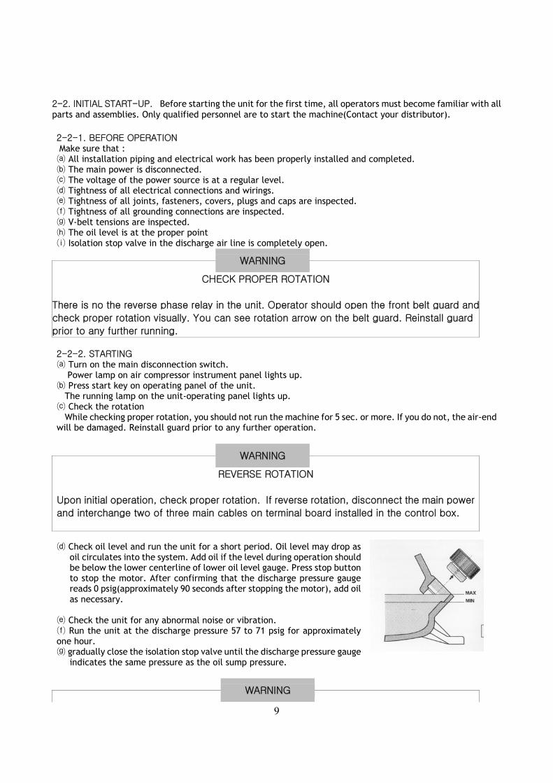
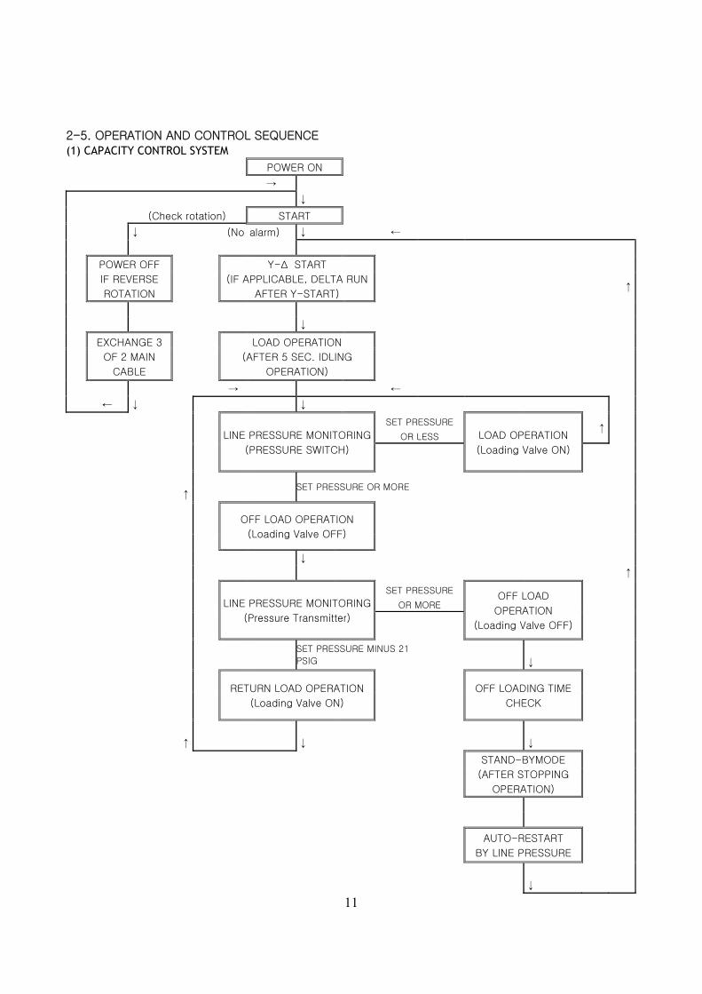
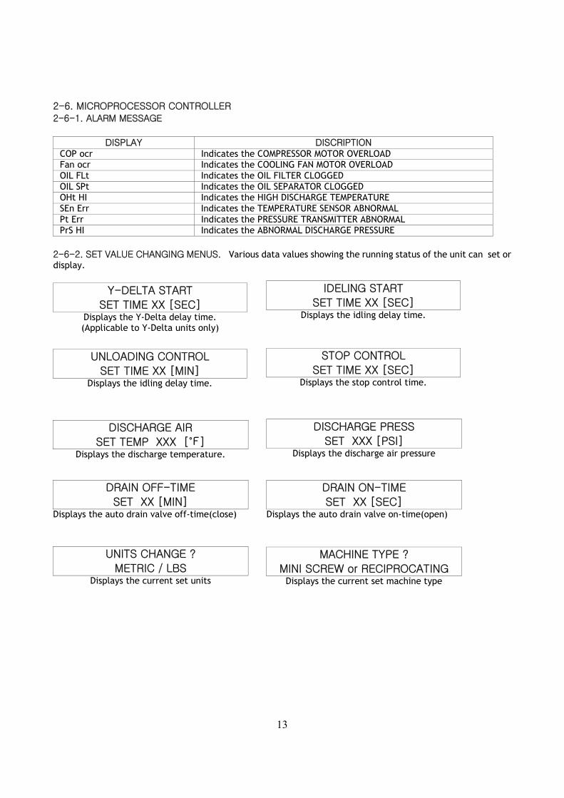
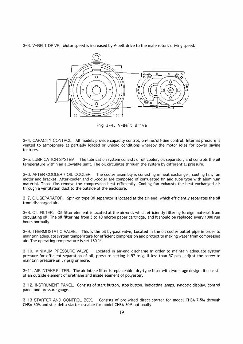
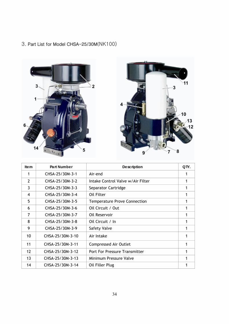
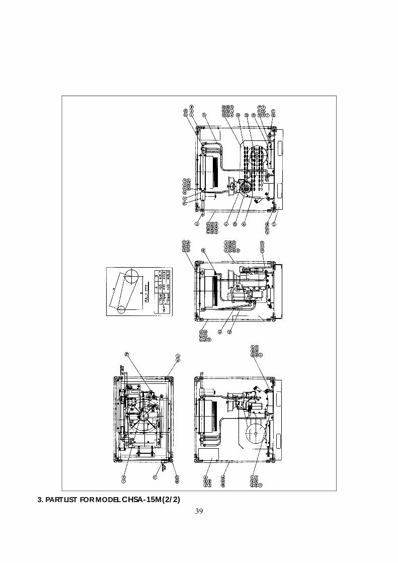
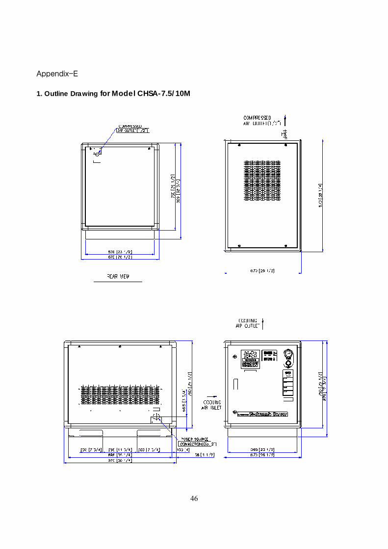