
Rotary-Linear Machines – A Survey
4
Rotary-Linear Machines – A Survey BENŢIA Ioana, SZABÓ Loránd Technical University of Cluj-Napoca Electrical Machines Department, Faculty of Electrical Engineering 28 Memorandumului str, 400114 Cluj, Romania e-mail: [email protected] Abstract – Certain industrial applications require both rotary and linear motion. The rotary-linear machine structure allows for simplified system design and a reduction in the number of components. It is ideal for use in tight fitting applications requiring precise two degrees of freedom, controllable motion, pick and place equipment, robotics, and a wide array of instrumentation. The paper presents a survey of the rotary-linear motors cited in the literature. There are also emphasized the advantages of the rotary-linear machine advantages for diverse specific industrial applications. There are also highlighted that construction of these machines is more complicated in comparison with the classical machines. The paper focuses on the special design and working principles of the machines taken into study. I. INTRODUCTION Since the usual commercial motor produces only one dimensional (linear or rotary) motion, the two-dimensional motion generally requires more than two motors. In modern industrial environment precise two-dimensional, both linear and rotary motions are required. Examples are the manufacturing of parts assembling, component insertion, and electrical wiring. Most of these high-performance manufacturing machines use cascaded X-Y tables with rotary motors and rotary-to-linear mechanical couplings. Though this is the most widely used method, it has the disadvantages of complex mechanical structure, frequent mechanical adjustments, high manufacturing/maintenance cost and low reliability [1]. In a direct drive mechanism the mechanical power is transferred directly to the load without any reductions, hence any mechanical couplers such as gears or belts for motion transformation are eliminated. It has the advantages of fast response, high flexibility and the overall control system may have a simple structure [2]. The use of electronic control systems with accurate position detection and rapid response allows two dimensional motions to be performed. This paper deals with some rotary-linear machines, which were chosen due to their outstanding structure, design and operating mode. II. ROTARY-LINEAR MACHINES A. Rotary-Linear Switched Reluctance Machine The first machine chosen to be detailed in the paper is a rotary-linear switched reluctance motor. It has three phases for the linear motion and four phases for rotation, as shown in Fig. 1. The rotor has a toothed structure to ensure appropriate flux path along the stators, air-gap and the rotor, and it has a uniform structure. The rotor has the degree-of-freedom in rotary and Z-directions. To prevent the rotor from Y-axis movement, the rotor axis is tightly fixed in the motor shell with the rotor pin and ball screws to facilitate Z-axis movement and rotary motion only [3]. The propulsion motor is based on the "straightened- out-and-rolling" version of a 6/4 pole rotary switched reluctance motor, along the Z-directions, as shown in Fig. 2. Two sets of 3-phase coil windings with wide magnetic teeth are employed on the moving platform. Fig. 1. Layout of the 2D motor [3]
description
Certain industrial applications require bothrotary and linear motion. The rotary-linear machinestructure allows for simplified system design and areduction in the number of components. It is ideal foruse in tight fitting applications requiring precise twodegrees of freedom, controllable motion, pick andplace equipment, robotics, and a wide array ofinstrumentation. The paper presents a survey of therotary-linear motors cited in the literature. There arealso emphasized the advantages of the rotary-linearmachine advantages for diverse specific industrialapplications. There are also highlighted thatconstruction of these machines is more complicated incomparison with the classical machines.
Transcript of Rotary-Linear Machines – A Survey
Rotary-Linear Machines – A Survey
BENŢIA Ioana, SZABÓ Loránd
Technical University of Cluj-Napoca Electrical Machines Department, Faculty of Electrical Engineering
28 Memorandumului str, 400114 Cluj, Romania e-mail: [email protected]
Abstract – Certain industrial applications require both rotary and linear motion. The rotary-linear machine structure allows for simplified system design and a reduction in the number of components. It is ideal for use in tight fitting applications requiring precise two degrees of freedom, controllable motion, pick and place equipment, robotics, and a wide array of instrumentation. The paper presents a survey of the rotary-linear motors cited in the literature. There are also emphasized the advantages of the rotary-linear machine advantages for diverse specific industrial applications. There are also highlighted that construction of these machines is more complicated in comparison with the classical machines. The paper focuses on the special design and working principles of the machines taken into study.
I. INTRODUCTION
Since the usual commercial motor produces only one dimensional (linear or rotary) motion, the two-dimensional motion generally requires more than two motors. In modern industrial environment precise two-dimensional, both linear and rotary motions are required. Examples are the manufacturing of parts assembling, component insertion, and electrical wiring. Most of these high-performance manufacturing machines use cascaded X-Y tables with rotary motors and rotary-to-linear mechanical couplings. Though this is the most widely used method, it has the disadvantages of complex mechanical structure, frequent mechanical adjustments, high manufacturing/maintenance cost and low reliability [1].
In a direct drive mechanism the mechanical power is transferred directly to the load without any reductions, hence any mechanical couplers such as gears or belts for motion transformation are eliminated. It has the advantages of fast response, high flexibility and the overall control system may have a simple structure [2]. The use of electronic control systems with accurate position detection and rapid response allows two dimensional motions to be performed.
This paper deals with some rotary-linear machines, which were chosen due to their outstanding structure, design and operating mode.
II. ROTARY-LINEAR MACHINES
A. Rotary-Linear Switched Reluctance Machine
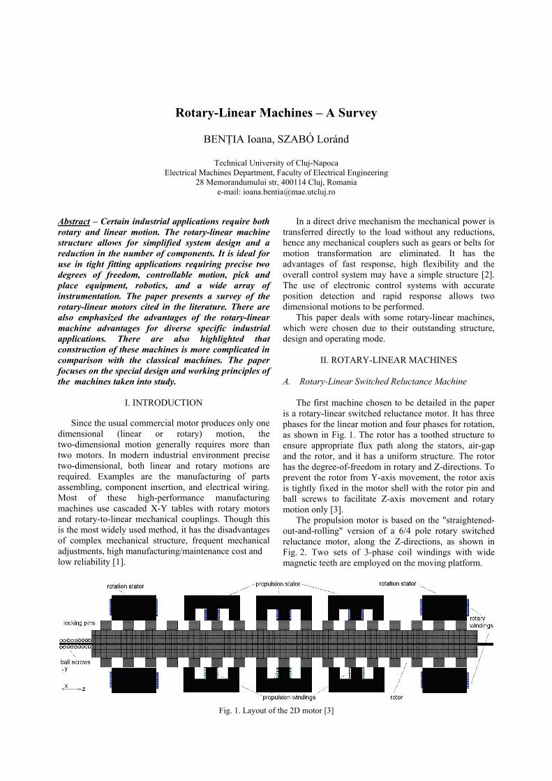
The first machine chosen to be detailed in the paper is a rotary-linear switched reluctance motor. It has three phases for the linear motion and four phases for rotation, as shown in Fig. 1. The rotor has a toothed structure to ensure appropriate flux path along the stators, air-gap and the rotor, and it has a uniform structure. The rotor has the degree-of-freedom in rotary and Z-directions. To prevent the rotor from Y-axis movement, the rotor axis is tightly fixed in the motor shell with the rotor pin and ball screws to facilitate Z-axis movement and rotary motion only [3].
The propulsion motor is based on the "straightened-out-and-rolling" version of a 6/4 pole rotary switched reluctance motor, along the Z-directions, as shown in Fig. 2. Two sets of 3-phase coil windings with wide magnetic teeth are employed on the moving platform.
Fig. 1. Layout of the 2D motor [3]
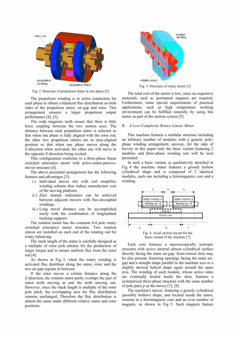
The propulsion winding is in series connection for each phase to obtain a balanced flux distribution on both sides of the propulsion stator, air-gap and rotor. This arrangement ensures a larger propulsion output performance [4], [5].
The wide magnetic teeth ensure that there is little force coupling between the two motion axes. The distance between each propulsion stator is selected so that when one phase is fully aligned with the rotor rod, the other two propulsion stators are in miss-aligned position so that when one phase moves along the Z-direction when activated, the other one will move in the opposite Z-direction being excited.
This configuration conforms to a three-phase linear switched reluctance motor with active-stator-passive-mover structure [6].
The above presented arrangement has the following features and advantages [3].
i.) Individual mover slot with coil simplifies winding scheme thus reduce manufacture cost of the moving platform.
ii.) Zero mutual inductance can be achieved between adjacent movers with flux-decoupled windings.
iii.) Long travel distance can be accomplished easily with the combination of longitudinal tracking supports
The rotation motor has the common 6/4 pole rotary switched reluctance motor structure. Two rotation stators are installed on each end of the rotating rod for rotary balancing.
The stack length of the stator is carefully designed as a multiple of rotor pole pitches for the production of larger torque and to ensure uniform flux from the rotor rod [4].
As shown in Fig. 3, when the rotary winding is activated flux distribute along the stator, rotor and the two air-gap regions in between.
If the rotor moves a certain distance along the Z-direction, the rotation stator partly overlaps the pair of stator teeth moving in and the teeth moving out. However, since the stack length is multiple of the rotor pole pitch, the overlapping area for flux distribution remains unchanged. Therefore the flux distribution is almost the same under different relative stator and rotor positions.
The total cost of the motor is low, since no expensive materials, such as permanent magnets are required. Furthermore, some special requirements of practical applications, such as high temperature working environment can be fulfilled naturally by using this motor as part of the motion system [5].
B. A Low-Complexity Rotary-Linear Motor
This machine features a modular structure including
an arbitrary number of modules with a generic poly-phase winding arrangement; anyway, for the sake of brevity in this paper only the basic variant featuring 2 modules and three-phase winding sets will be next presented.
In such a basic variant, as qualitatively sketched in Fig. 4 the machine stator features a grossly hollow cylindrical shape and is composed of 2 identical modules, each one including a ferromagnetic core and a winding.
Each core features a macroscopically isotropic structure with active internal almost cylindrical surface directly facing the main air-gap. Semi-closed slots may be also present, featuring openings facing the main air-gap and a straight shape parallel to the machine axis or a slightly skewed helical shape again around the same axis. The winding of each module, whose active sides are eventually hosted inside the slots, features a symmetrical three-phase structure with the same number of pole pairs p as the mover [7], [8].
The machine's mover, featuring a grossly cylindrical (possibly hollow) shape, and located inside the stator, consists in a ferromagnetic core and an even number of magnets, as shown in Fig. 5. Such magnets feature
Fig. 2. Structure of propulsion stator in one phase [5]
Fig. 3. Structure of rotary motor [3]
Fig. 4. Axial section layout for the
basic variant of the machine [7]

basically the same sector hollow-cylindrical shape and the same grossly radial magnetization pattern, with outward magnetization direction for half of them and inward for the others [7]. The core, which features a disgustingly cylindrical, eventually hollow, shape hosts in the middle of its external surface the magnets, which are attached in aligned axial positions forming a sequence of alternated poles along the tangential direction, as usual.
It is assumed that a suited frame encloses the stator modules and that a mechanical shaft supports the active parts of the mover while transmitting outside the generated wrench. The shaft is supposed to be connected in turn to the stator frame by means of suitable bearings, permitting the mover to exhibit only the prescribed rotary and linear motions vs. stator.
According to the above description, each stator module basically features the same structure type as a common stator for brushless, synchronous or induction machines. Therefore, the core may be manufactured either in standard way by axially staking suitably shaped laminations, or by using innovative solutions such as iron powder technology.
Analogously, the winding may be manufactured using either the classical processes related to distributed layouts, or the more modern tooth-wound coils technique.
The mover features also an arrangement very similar to rotors of common surface-magnets rotary isotropic brushless machines except for the enlarged axial length of the core, thus also permitting to manufacture this part using common solutions [8].
C. Rotary-Linear Induction Motors
Rotary-linear induction motors are designed as tubular motors, usual with a double layer secondary. This category of motors can be classified as follows [9]:
i.) Motors consisting of a certain number of three phase stators producing magnetic field, arranged axially, with the field axes of neighbouring stators being shifted through a certain angle (Fig. 6).
ii.) Double-primary (twin armature) motors. Where one primary is a stator of a three-phase ac motor connected in tandem with a tubular primary that produces a translator motion (Fig. 7).
iii.) Motors with single helical wound primary stack.
iv.) Double winding motors, where the primary laminated stack has two independent windings to produce, independently, the rotating and the travelling fields (Fig. 8).
The stator of the motor shown in Fig. 8 contains two windings. One of them, built similarly to the winding of a conventional rotating motor, creates a rotating field. The other one, built similarly to the winding of a tubular linear induction motor, generates a travelling field. Both fields acting on the common rotor, consisted of two homogeneous layers, contribute to the rise of two forces: linear (axial) and rotary (circumferential) ones. Changing the supply voltage or frequency, the rotor’s motion can be influenced, changing thereby the direction and value of the rotor’s velocity.
Fig. 5. Partial view of 3-D model (half of front section hidden) [8]
Fig. 6. Multi-armature rotary-linear induction motor with
travelling magnetic field: 1-single primary core, 2-secondary [9]
Fig. 7. Twin-armature rotary-linear induction motor:1-stator producing rotating field, 2-tubular primary
producing travelling field, 3-secondary [9]
Fig. 8. Double-winding rotary-linear induction motor [10]

D. Rotary-Linear Motor Composed of Four Primaries with Independently Energized Ring-Windings
It can be considered that this motor belongs to the
first category mentioned at i.) section. It consists of plural short primary linear induction motors (LIMs) arranged on the same circumference, similar to a tubular LIM. Independently energized ring-windings of double-layer to each primary were adopted. By using ring-winding instead of usual drum-one, the space between neighboring primaries is reduced, and the sufficient rotary-force can be developed without the intermediate primary-yokes in the rotary direction.
Also the secondary solid-conductors is combine into one member. When the supply current for each primary winding has an appropriate phase-difference from those of the neighboring primaries, the secondary currents flow in the helical direction. Owing to the peripheral components of the secondary currents, the whole motor produces subsidiary rotary-force besides the principal linear-one [11].
Fig. 9 shows the structure of the proposed rotary-linear induction motor (RLIM).
Each primary winding is energized by multiphase supply with independent phase shifter, and the cylindrical secondary solid-conductor is separated from its back iron. This conductor is movable, supported by a rotary-linear bearing system. Controlling the phase angles of supply currents in each primary winding, the operation of the secondary conductor is possible in any of four quadrants of the linear-rotary plane. Furthermore, by adopting ring-winding, the pole pitch of the primary winding can be altered by supplying appropriate slot currents even after the machine has been manufactured [11].
III. CONCLUSIONS
The paper presented a synthesis of the main types of rotary-linear motors cited in literature. The combination of a rotary and a linear motion along the same axis is used in several industrial machines and also in other applications, such as the combined actuation of pairs of basic functions such as propulsion, steering and active suspension, which are performed by active wheels in advanced electric and hybrid vehicles.
Finally it can be stated that rotary-linear machines could replace the conventional electrical machines and
actuators used in different specific advanced industrial applications [12].
ACKNOWLEDGMENT
This paper was supported by the project "Doctoral
studies in engineering sciences for developing the knowledge based society–SIDOC" contract no. POSDRU/88/1.5/S/60078, project co-funded from European Social Fund through Sectorial Operational Program Human Resources 2007-2013.
REFERENCES
[1] E.R. Pelta, "Two-axis Sawyer motor for motion systems," IEEE Control Systems Magazine, October 1987, pp. 1-24.
[2] I. Boldea and S. A. Nasar, "Linear Electric Actuators and Generators," Cambridge University Press, 1997.
[3] J.F. Pan, N.C. Cheung and G. Cao, "A Rotary-Linear Switched Reluctance Motor," Proceedings of the 3rd International Conference on Power Electronics Systems and Applications (PESA '2009), pp. 1-4.
[4] J.F. Pan, N.C. Cheung and C.Z. Cao, "Investigation of a rotary linear switched reluctance motor," Proceedings of the XIX International Conference on Electrical Machines (ICEM '2010), Rome (Italy), 2010.
[5] F. Pan and N.C. Cheung, "A Magnetically Levitated Linear Rotary Guide for Linear Rotary Motors," Proceedings of the International Conference on Electrical Engineering (ICEE '2008), Okinawa (Japan), 2008.
[6] R. Krishnan, "Switched Reluctance Motor Drives: Modeling, Simulation, Analysis, Design, and Applications," CRC Press, Boca Raton (FL, USA), 2001.
[7] P. Bolognesi, O. Bruno, F. Papini, V. Biagini and L. Taponecco, "A Low-Complexity Rotary-Linear Motor Useable for Actuation of Active Wheels”, Proceedings of the International Symposium on Power Electronics, Electrical Drives, Automation and Motion (SPEEDAM '2010), Pisa (Italy), 2010, pp. 331-338.
[8] M. Bertoluzzo, P. Bolognesi, O. Bruno and G. Buja, "A distributed driving and steering system for electric vehicles using rotary-linear motors," Proceedings of the International Symposium on Power Electronics, Electrical Drives, Automation and Motion (SPEEDAM '2010), Pisa (Italy), 2010, pp. 1156-1159.
[9] J.F. Gieras, "Linear Induction Drives," Oxford University Press Inc., New York (USA), 1994.
[10] E.A. Mendrela, "Double-winding rotary-linear induction motor,” IEEE Transactions on Energy Conversion, vol. EC-2, pp. 47–54, 1987.
[11] W.J Jeon, M. Tanabiki, T. Onuki and J.Y. Yoo, "Rotary-Linear Induction Motor Composed of Four Primaries with Independently Energized Ring-Windings," Conference Record of the IEEE Industry Applications Conference, (32nd IAS Annual Meeting, IAS '97), vol. 1, New Orleans (USA), 1997, pp. 365-372.
[12] I. Benţia, M. Ruba, L. Szabó, "Modular Electrical Machines – A Survey," Proceedings of the International Scientific Conference MicroCAD '2010, Miskolc (Hungary), Section K (Electrotehnics and Electronics), 2010, pp. 87-92.
Fig .9. The rotary-linear induction motor's structure [11]


