Xpac Series 2 Rotary, Linear Actuators, and...
8
1 Electraulic™ Actuation Xpac Series 2 Rotary, Linear Actuators, and Drives ISO 9001:2008 Certified BULLETIN XPAC-2
Transcript of Xpac Series 2 Rotary, Linear Actuators, and...
1
Xpac – 2
Electraulic™ Actuation
Xpac Series 2Rotary, Linear Actuators, and Drives
ISO 9001:2008 CertifiedBULLET IN XPAC-2

Xpac SeriesThe REXA Xpac is a superior positioning device that is particularly well suited for applications requiring critical control and high reliability. The product is designed to thrive in the most hostile ambient environ-ments and will harness control of the most severe process conditions. Our actuators and drives provide to final control elements capabilities to match the most sophisticated instrumentation and Distributed Control Systems.
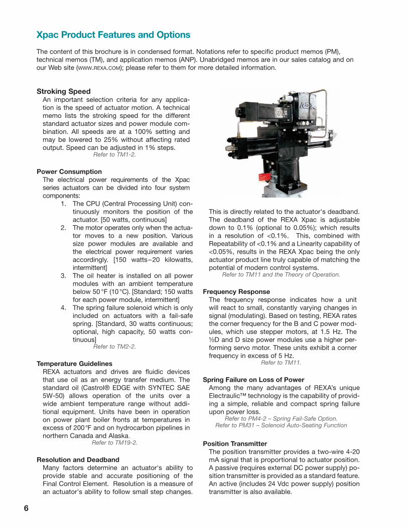
Basic ComponentsThere are two major components to the Xpac: the actuator, which mounts to the driven device, consists of the cylinder, feedback and Electraulic™ power module; and, the control enclosure, which is separately mounted, consists of the electronics and power supplies. The Electraulic™ power module is REXA’s patented self-con-tained hydraulic pumping system that manages oil pressure and flow rates to and from a double acting cylinder. A dedicated microprocessor, the CPU, in the control enclosure operates the Xpac. This combination of mechan-ical, hydraulic and electronic technologies produces the state-of-the-art actuator design.
Standard ConfigurationsREXA offers as standard: linear actuators (L series) with thrusts ranging from 2000 to 120000 lb and strokes to six inches; rotary units (R series) with rotations up to 90 degrees and torques ranging from 2 500 to 400000 lb·in; and drive configurations (D series) with torques up to 200000 lb·in and rotations up to 120 degrees.
Custom crafted units can provide considerably greater thrust or torque and longer strokes or rotation. Drives with multi-million pound inch capabilities are available.
The Electraulic power module is available in B, C, ½D and D sizes. The different power modules provide vari-ous stroking speeds for a given cylinder size as well as enhanced frequency response. This approach to prod-uct configuration offers a high degree of commonality to reduce spare parts inventory.
Advantages � Controllability—low deadband, immediate response, high stiffness, 100% modulating duty cycle
The unit can respond to control signal changes as low as 0.1% (optional to 0.05%).
� HydrauliC stability The process forces acting on the final control element will not move the Xpac.
� total eleCtriC operation—self-contained, discrete movement, consistency of operation A single electrical power source supplied directly to the control enclosure operates all aspects of the Xpac. Remote pumps or hydraulic sources are not required. Low power consumption is inher-ent, with the motor only turning when repositioning is required.
� low maintenanCe Few moving parts (most of which are immersed in high quality motor oil) and sealed construction eliminate the need for routine mainte-nance. Parts inventory and repairs are simplified through consistent and modular design.
� eleCtroniC Calibration Set-up is quick and simple with keypad calibration. There are no torque switches to adjust, potentiometers to turn, or dip switches to set.
� Custom mounting REXA’s linear, rotary and drive configurations can be applied to virtu-ally any installation.
� Failure position A known position upon loss of electrical power can be provided by either a mechanical spring or hydraulic accumulator.
22
Due to continuing design changes and improvements, all specifications are subject to change.
Xpac – 2OperationBy using the stroke and signal ranges set during calibration, the Central Processing Unit (CPU) converts the control signal into a target position. The actual position is determined through the active feedback assem-bly mounted on the actuator. The difference between the target and actual position is the error. If the error exceeds the deadband (user set), then the CPU will initiate corrective action by starting the motor.
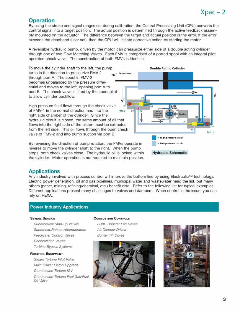
A reversible hydraulic pump, driven by the motor, can pressurize either side of a double acting cylinder through one of two Flow Matching Valves. Each FMV is comprised of a ported spool with an integral pilot operated check valve. The construction of both FMVs is identical.
To move the cylinder shaft to the left, the pump turns in the direction to pressurize FMV-2 through port A. The spool in FMV-2 becomes unbalanced by the pressure differ-ential and moves to the left, opening port A to port E. The check valve is lifted by the spool pilot to allow cylinder backflow.
High pressure fluid flows through the check valve of FMV-1 in the normal direction and into the right side chamber of the cylinder. Since the hydraulic circuit is closed, the same amount of oil that flows into the right side of the piston must be extracted from the left side. This oil flows through the open check valve of FMV-2 and into pump suction via port B.
By reversing the direction of pump rotation, the FMVs operate in reverse to move the cylinder shaft to the right. When the pump stops, both check valves close. The hydraulic oil is locked within the cylinder. Motor operation is not required to maintain position.
ApplicationsAny industry involved with process control will improve the bottom line by using Electraulic™ technology. Electric power generation, oil and gas pipelines, municipal water and wastewater head the list, but many others (paper, mining, refining/chemical, etc.) benefit also. Refer to the following list for typical examples. Different applications present many challenges to valves and dampers. When control is the issue, you can rely on REXA.
Power Industry Applications
severe service Combustion Controls
Supercritical Start-up Valves FD/ID Booster Fan Drives
Superheat/Reheat Attemperators Air Damper Drives
Feedwater Control Valves Burner Tilt Drives
Recirculation Valves
Turbine Bypass Systems
rotating equipment
Steam Turbine Pilot Valve
Main Power Piston Upgrade
Combustion Turbine IGV
Combustion Turbine Fuel Gas/Fuel Oil Valve
3
Hydraulic Schematic
4
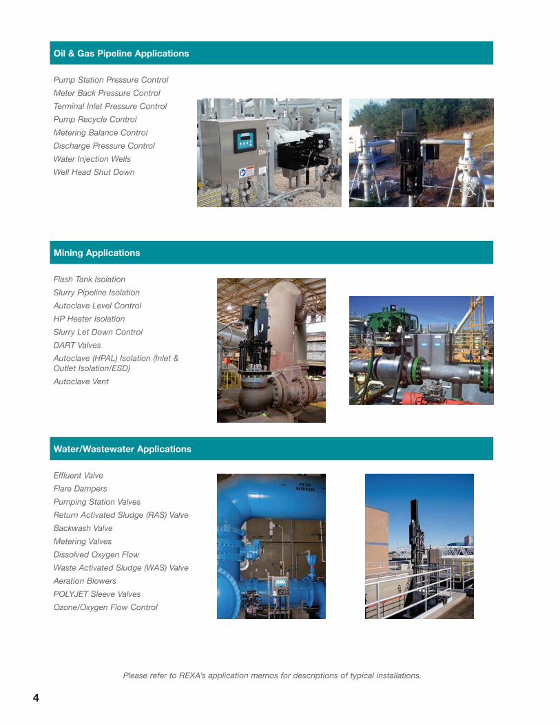
Oil & Gas Pipeline Applications
Pump Station Pressure Control
Meter Back Pressure Control
Terminal Inlet Pressure Control
Pump Recycle Control
Metering Balance Control
Discharge Pressure Control
Water Injection Wells
Well Head Shut Down
Mining Applications
Flash Tank Isolation
Slurry Pipeline Isolation
Autoclave Level Control
HP Heater Isolation
Slurry Let Down Control
DART Valves
Autoclave (HPAL) Isolation (Inlet & Outlet Isolation/ESD)
Autoclave Vent
Water/Wastewater Applications
Effluent Valve
Flare Dampers
Pumping Station Valves
Return Activated Sludge (RAS) Valve
Backwash Valve
Metering Valves
Dissolved Oxygen Flow
Waste Activated Sludge (WAS) Valve
Aeration Blowers
POLYJET Sleeve Valves
Ozone/Oxygen Flow Control
Please refer to REXA’s application memos for descriptions of typical installations.
5
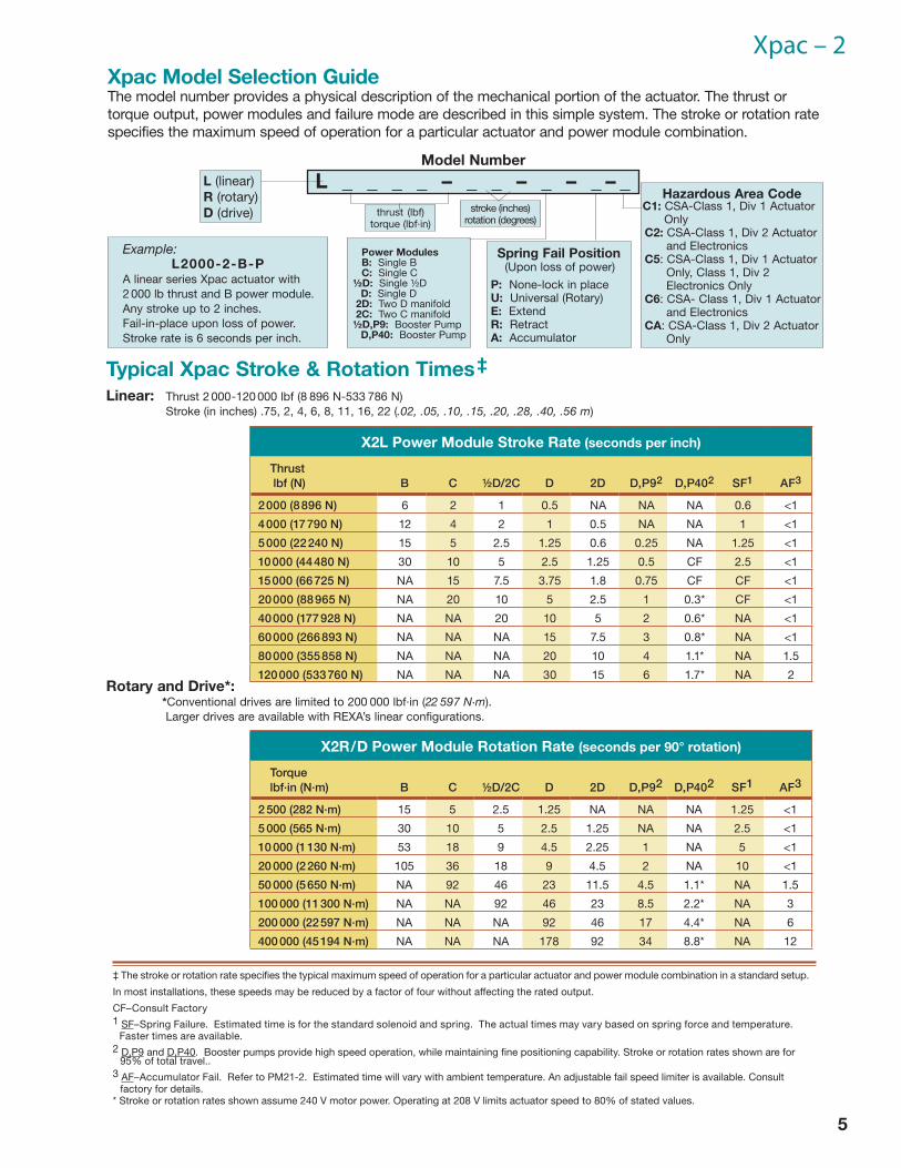
Xpac – 2Xpac Model Selection GuideThe model number provides a physical description of the mechanical portion of the actuator. The thrust or torque output, power modules and failure mode are described in this simple system. The stroke or rotation rate specifies the maximum speed of operation for a particular actuator and power module combination.
L _ _ _ _ – _ _ – _ – _ – _
Spring Fail Position(Upon loss of power)
P: None-lock in placeU: Universal (Rotary)E: ExtendR: RetractA: Accumulator
L (linear)R (rotary)D (drive)
Power ModulesB: Single BC: Single C
½D: Single ½DD: Single D
2D: Two D manifold2C: Two C manifold½D,P9: Booster Pump
D,P40: Booster Pump
Example:L2000-2-B-P
A linear series Xpac actuator with 2 000 lb thrust and B power module. Any stroke up to 2 inches. Fail-in-place upon loss of power. Stroke rate is 6 seconds per inch.
stroke (inches)rotation (degrees)
thrust (lbf)torque (lbf·in)
Model Number
Typical Xpac Stroke & Rotation Times ‡Linear: Thrust 2 000-120 000 lbf (8 896 N-533 786 N) Stroke (in inches) .75, 2, 4, 6, 8, 11, 16, 22 (.02, .05, .10, .15, .20, .28, .40, .56 m)
X2L Power Module Stroke Rate (seconds per inch)
Thrust lbf (N) B C ½D/2C D 2D D,P92 D,P402 SF1 AF3
2 000 (8 896 N) 6 2 1 0.5 NA NA NA 0.6 <1
4 000 (17 790 N) 12 4 2 1 0.5 NA NA 1 <1
5 000 (22 240 N) 15 5 2.5 1.25 0.6 0.25 NA 1.25 <1
10 000 (44 480 N) 30 10 5 2.5 1.25 0.5 CF 2.5 <1
15 000 (66 725 N) NA 15 7.5 3.75 1.8 0.75 CF CF <1
20 000 (88 965 N) NA 20 10 5 2.5 1 0.3* CF <1
40 000 (177 928 N) NA NA 20 10 5 2 0.6* NA <1
60 000 (266 893 N) NA NA NA 15 7.5 3 0.8* NA <1
80 000 (355 858 N) NA NA NA 20 10 4 1.1* NA 1.5
120 000 (533 760 N) NA NA NA 30 15 6 1.7* NA 2
X2R/D Power Module Rotation Rate (seconds per 90° rotation)
Torque lbf·in (N·m) B C ½D/2C D 2D D,P92 D,P402 SF1 AF3
2 500 (282 N·m) 15 5 2.5 1.25 NA NA NA 1.25 <1
5 000 (565 N·m) 30 10 5 2.5 1.25 NA NA 2.5 <1
10 000 (1 130 N·m) 53 18 9 4.5 2.25 1 NA 5 <1
20 000 (2 260 N·m) 105 36 18 9 4.5 2 NA 10 <1
50 000 (5 650 N·m) NA 92 46 23 11.5 4.5 1.1* NA 1.5
100 000 (11 300 N·m) NA NA 92 46 23 8.5 2.2* NA 3
200 000 (22 597 N·m) NA NA NA 92 46 17 4.4* NA 6
400 000 (45 194 N·m) NA NA NA 178 92 34 8.8* NA 12
‡ The stroke or rotation rate specifies the typical maximum speed of operation for a particular actuator and power module combination in a standard setup.
In most installations, these speeds may be reduced by a factor of four without affecting the rated output.
CF–Consult Factory1 SF–Spring Failure. Estimated time is for the standard solenoid and spring. The actual times may vary based on spring force and temperature.
Faster times are available.2 D,P9 and D,P40. Booster pumps provide high speed operation, while maintaining fine positioning capability. Stroke or rotation rates shown are for
95% of total travel..3 AF–Accumulator Fail. Refer to PM21-2. Estimated time will vary with ambient temperature. An adjustable fail speed limiter is available. Consult
factory for details.* Stroke or rotation rates shown assume 240 V motor power. Operating at 208 V limits actuator speed to 80% of stated values.
Rotary and Drive*: *Conventional drives are limited to 200 000 lbf·in (22 597 N·m). Larger drives are available with REXA’s linear configurations.
Hazardous Area Code C1: CSA-Class 1, Div 1 Actuator OnlyC2: CSA-Class 1, Div 2 Actuator and ElectronicsC5: CSA-Class 1, Div 1 Actuator Only, Class 1, Div 2 Electronics OnlyC6: CSA- Class 1, Div 1 Actuator and ElectronicsCA: CSA-Class 1, Div 2 Actuator Only
6
Stroking SpeedAn important selection criteria for any applica-tion is the speed of actuator motion. A technical memo lists the stroking speed for the different standard actuator sizes and power module com-bination. All speeds are at a 100% setting and may be lowered to 25% without affecting rated output. Speed can be adjusted in 1% steps.
Refer to TM1-2.
Power ConsumptionThe electrical power requirements of the Xpac series actuators can be divided into four system components:
1. The CPU (Central Processing Unit) con-tinuously monitors the position of the actuator. [50 watts, continuous]
2. The motor operates only when the actua-tor moves to a new position. Various size power modules are available and the electrical power requirement varies accordingly. [150 watts – 20 kilowatts, intermittent]
3. The oil heater is installed on all power modules with an ambient temperature below 50 °F (10 °C). [Standard; 150 watts for each power module, intermittent]
4. The spring failure solenoid which is only included on actuators with a fail-safe spring. [Standard, 30 watts continuous; optional, high capacity, 50 watts con-tinuous]
Refer to TM2-2.
Temperature GuidelinesREXA actuators and drives are fluidic devices that use oil as an energy transfer medium. The standard oil (Castrol® EDGE with SYNTEC SAE 5W-50) allows operation of the units over a wide ambient temperature range without addi-tional equipment. Units have been in operation on power plant boiler fronts at temperatures in excess of 200°F and on hydrocarbon pipelines in northern Canada and Alaska.
Refer to TM19-2.
Resolution and DeadbandMany factors determine an actuator's ability to provide stable and accurate positioning of the Final Control Element. Resolution is a measure of an actuator's ability to follow small step changes.
This is directly related to the actuator's deadband. The deadband of the REXA Xpac is adjustable down to 0.1% (optional to 0.05%); which results in a resolution of <0.1%. This, combined with Repeatability of <0.1% and a Linearity capability of <0.05%, results in the REXA Xpac being the only actuator product line truly capable of matching the potential of modern control systems.
Refer to TM11 and the Theory of Operation.
Frequency ResponseThe frequency response indicates how a unit will react to small, constantly varying changes in signal (modulating). Based on testing, REXA rates the corner frequency for the B and C power mod-ules, which use stepper motors, at 1.5 Hz. The ½D and D size power modules use a higher per-forming servo motor. These units exhibit a corner frequency in excess of 5 Hz.
Refer to TM11.
Spring Failure on Loss of PowerAmong the many advantages of REXA’s unique Electraulic™ technology is the capability of provid-ing a simple, reliable and compact spring failure upon power loss.
Refer to PM4-2 – Spring Fail-Safe Option.Refer to PM31 – Solenoid Auto-Seating Function
Position TransmitterThe position transmitter provides a two-wire 4-20 mA signal that is proportional to actuator position. A passive (requires external DC power supply) po-sition transmitter is provided as a standard feature. An active (includes 24 Vdc power supply) position transmitter is also avail able.
Xpac Product Features and Options
The content of this brochure is in condensed format. Notations refer to specific product memos (PM), technical memos (TM), and application memos (ANP). Unabridged memos are in our sales catalog and on our Web site (www.rexa.com); please refer to them for more detailed information.
7
Xpac – 2Limit Switches
Limit switches provide a contact closure when an actuator or drive reaches a predetermined point in its stroke. The standard electrical enclosure includes two SPDT relays which can be used to indicate user defined stroke limits. Optionally available independent mechanical limit switches can be yoke or feedback housing mounted.
Refer to PM13-2 – Limit Switches.
Alarm IndicatorTwo additional relays are provided as standard equipment and dedicated to operational indica-tion. The Alarm relay will signal when the actuator is unable to follow the control signal for any reason. The Warning relay signals a condition that requires attention, but does not prevent normal operation of the unit.
Accumulator Failure SystemREXA’s unique accumulator technology uses the power module to automatically recharge the accu-mulator, thus eliminating the need for a separate recharge system. A failure may be initiated by loss of electrical power or an independent trip signal. After a failure the accumulator is recharged by the actuator’s power module prior to resuming normal operation.
Refer to PM21-2 – Accumulator Option.
Manual OverrideWhen electric power is unavailable, movement of REXA actuators or drives can be provided by a manual operator. Two types are available:
1. Handwheel/Drill Drive—declutchable, attached to the outboard end of the motor.
2. Manual Hydraulic Pump—con-nected to the cylinder side of the hydraulic circuit.
Both methods make use of the unit’s hydraulic system.
Pulse Operating SystemThis unique operating system allows control of the Xpac via pulsed voltage signals. In most installations, the Xpac will directly replace an obsolete gear motor operator and eliminate the requirement of interposing relays or con-tactors.
Refer to PM16-2 – Pulse Operating System.
Ancillary ControlThe touch pad mounted on the door of the con-trol enclosure provides non-intrusive access for control and calibration of each unit. An additional manual control station may be located remote from the control enclosure.
Booster Pump ConfigurationA dual pump operator utilizing a standard Xpac power module and a large capacity Booster Pump is available. The power module provides fine posi-tioning, while a separate volume booster pump pro-vides the speed. Duty cycle for the booster pump is low because it only responds to large position changes. The power module will make small changes in position. This dual pump operation allows REXA to extend its unique capabilities to large thrust or torque units with high-speed operation.
Refer to PM23-2 – Booster Pump Option.
Surge or Trip ControlThe purpose of a surge or trip feature is to provide high speed motion in one direction to limit the effect of an infrequent process upset. This motion can be to an intermediate point (surge) or to the end of stroke (trip). The surge control package consists of three main components: mechanical spring, solenoid and solid state relay. An additional cali-bration parameter is included in the setup menu to allow user-defined surge or trip activation settings.
Environmental RatingsThe standard environmental rating for the electrical enclosure and actuator is NEMA 4. Optional elec-trical enclosures are available in either stainless steel or fiberglass to meet a NEMA 4X rating.
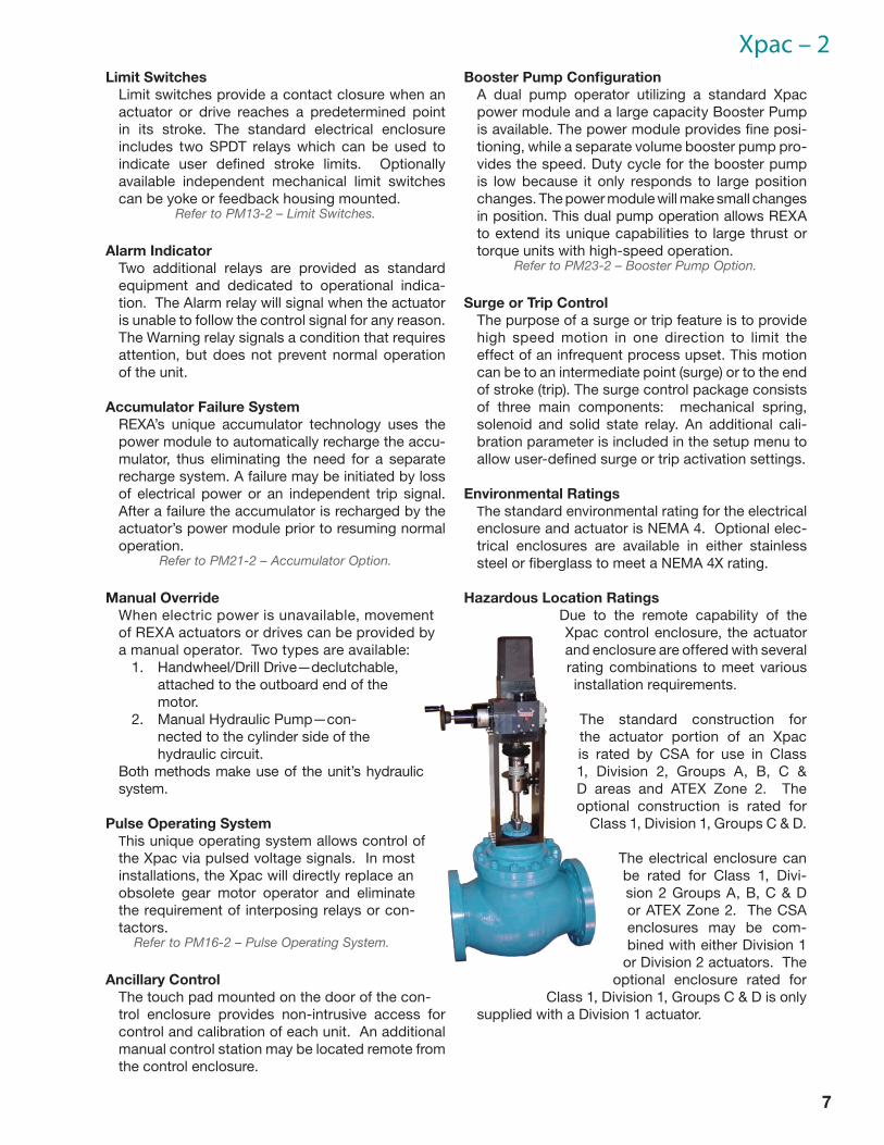
Hazardous Location RatingsDue to the remote capability of the Xpac control enclosure, the actuator and enclosure are offered with several rating combinations to meet various installation requirements.
The standard construction for the actuator portion of an Xpac is rated by CSA for use in Class 1, Division 2, Groups A, B, C & D areas and ATEX Zone 2. The optional construction is rated for
Class 1, Division 1, Groups C & D.
The electrical enclosure can be rated for Class 1, Divi-sion 2 Groups A, B, C & D or ATEX Zone 2. The CSA enclosures may be com-bined with either Division 1
or Division 2 actuators. The optional enclosure rated for
Class 1, Division 1, Groups C & D is only supplied with a Division 1 actuator.
8
REXA Xpac Specifications
ELECTRAULIC™ ACTUATION
09/13
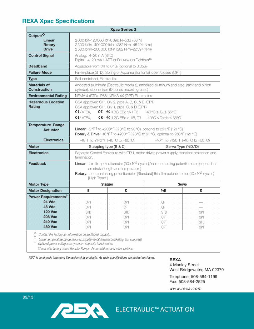
Xpac Series 2
Output:
LinearRotaryDrive
2 000 lbf – 120 000 lbf (8 896 N – 533 786 N)2 500 lbf·in – 400 000 lbf·in (282 N·m – 45 194 N·m)2 500 lbf·in –200 000 lbf·in (282 N·m –22 597 N·m)
Control Signal Analog: 4– 20 mA (STD)Digital: 4–20 mA HART or Foundation Fieldbus™
Deadband Adjustable from 5% to 0.1% (optional to 0.05%)
Failure Mode Fail-in-place (STD); Spring or Accumulator for fail open/closed (OPT)
Type Self-contained, Electraulic
Materials of Construction
Anodized aluminum (Electraulic module), anodized aluminum and steel (rack and pinion cylinder), steel or iron (D series mounting base)
Environmental Rating NEMA 4 (STD); IP66; NEMA 4X (OPT) Electronics
Hazardous Location Rating
CSA approved Cl 1, Div 2, grps A, B, C, & D (OPT)CSA approved Cl 1, Div 1, grps C, & D (OPT)
/ ATEX, II 3G EEx nA II T3 -40 °C ≤ Ta ≤ 65 °C
/ ATEX, II 2G EEx 'd' iiB, T3 -40°C ≤ Tamb ≤ 65°C
Temperature RangeActuator
Electronics
Linear: -5 °F ‡ to +200 °F (-20 °C to 93 °C), optional to 250 °F (121 °C)Rotary & Drive: -10 °F ‡ to +200 °F (-23 °C to 93 °C), optional to 250 °F (121 °C)
-40 °F to +140 °F (-40 °C to +60 °C) -40 °F to +120 °F (-40 °C to +50 °C)
Motor Stepping type (B & C) Servo Type (½D / D)
Electronics Separate Control Enclosure with CPU, motor driver, power supply, transient protection and termination.
Feedback Linear: thin film potentiometer (50 x 106 cycles) / non-contacting potentiometer [dependent on stroke length and temperature]
Rotary: non-contacting potentiometer [Standard] thin film potentiometer (10 x 106 cycles) [High Temp.]
Motor Type Stepper Servo
Motor Designation B C ½D D
Power Requirements†
24 Vdc48 Vdc120 Vac208 Vac240 Vac480 Vac
OPTOPTSTDOPTOPTOPT
OPT CFSTDOPTOPTOPT
CFCFSTDOPTOPTOPT
——OPTOPTSTDOPT
Contact the factory for information on additional capacity.‡ Lower temperature range requires supplemental thermal blanketing (not supplied).† Optional power voltages may require separate transformers. Check with factory about Booster Pumps, Accumulators, and other options.
REXA is continually improving the design of its products. As such, specifications are subject to change. REXA4 Manley StreetWest Bridgewater, MA 02379
Telephone: 508-584-1199Fax: 508-584-2525
www.rexa.com