Rotary Encoders with Mitsubishi Interface - HEIDENHAIN · 2 Rotary encoders with Mitsubishi...
12
June 2014 Product Overview Rotary Encoders with Mitsubishi Interface
Transcript of Rotary Encoders with Mitsubishi Interface - HEIDENHAIN · 2 Rotary encoders with Mitsubishi...

June 2014
Product Overview
Rotary Encoders
with Mitsubishi Interface

2
Rotary encoders with Mitsubishi interface
The rotary encoders described in this Product Overview were conceived specifi cally for direct connection to Mitsubishi controls with Mitsubishi interface ( .
Further Information
For further information on the mechanical design of rotary encoders, please refer to the Rotary Encoders catalog.
Mechanical designs
These rotary encoders are suitable, for example, for use on servo axes and spindles in machine tools. They are mounted rotary encoders with IP 67 protection on the housing and IP 64 at the shaft inlet.
The ECN/EQN 400 M rotary encoders
with stator coupling have integrated bearings. Their stator coupling compensates radial runout and alignment errors without signifi cantly reducing the accuracy. The encoder shaft is directly connected with the shaft to be measured. During angular acceleration of the shaft, the stator coupling must absorb only that torque caused by friction in the bearing.
The ROC/ROQ 400 M rotary encoders for
separate shaft coupling have integral bearings and a solid shaft. The shaft coupling compensates axial motion and misalignment (radial and angular offset) between the encoder shaft and measured shaft. This relieves the encoder bearing of additional external loads that would otherwise shorten its service life. Diaphragm and metal bellows couplings designed to connect the rotor of the ROC/ROQ 400 M encoders are available (see Shaft couplings in the Rotary Encoders catalog).

3
Contents
Specifi cations Absolute rotary encoders
Mounted stator coupling ECN 400 M/EQN 400 M series 4
Separate shaft coupling ROC 400 M/ROQ 400 M series with synchro fl ange
6
ROC 400 M/ROQ 400 M series with synchro fl ange
8
Electrical connection Pin layout 10
Cable 11

4
ECN/EQN 400 M series
• Absolute rotary encoders with mounted stator coupling
• Blind hollow shaft or hollow through shaft
• Mitsubishi interface
=Bearing ofmating shaft=Required mating dimensions = Measuring point for operating temperature = Connector coding = Clamping screw with hexalobular socket X8, tightening torque 1.1 ± 0.1 Nm= Compensation of mounting tolerances and thermal expansion, no dynamic motion permitted=Directionofshaft rotation for output signals as per the interface description = Clamping ring on housing side (status upon delivery) = Clamping ring on coupling side (optionally mountable)
5
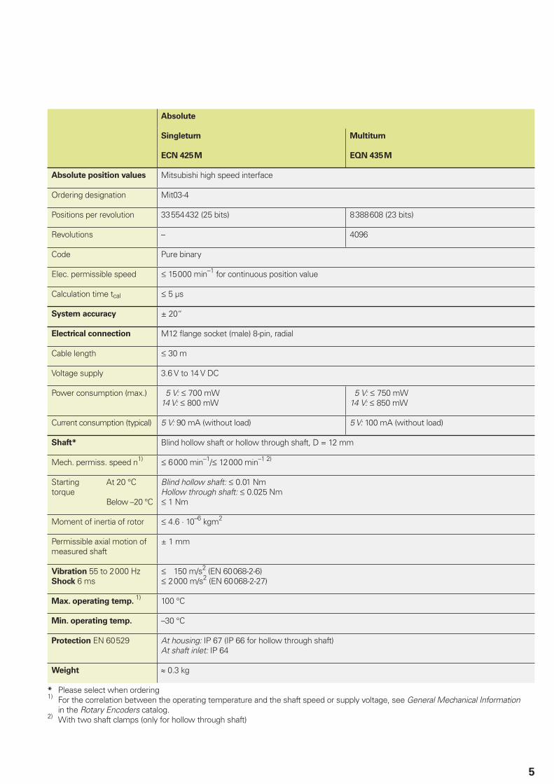
Absolute
Singleturn Multiturn
ECN 425 M EQN 435 M
Absolute position values Mitsubishi
Ordering designation Mit03-4
Positions per revolution 33 554 432 (25 bits) 8 388 608 (23 bits)
Revolutions – 4096
Code Pure binary
Elec. permissible speed 15 000 min–1 for continuous position value
Calculation time tcal 5 µs
System accuracy ± 20“
Electrical connection M12 fl ange socket (male) 8-pin, radial
Cable length 30 m
Voltage supply 3.6 V to 14 V DC
Power consumption (max.) 5 V: 700 mW14 V: 800 mW
5 V: 750 mW14 V: 850 mW
Current consumption (typical) 5 V: 90 mA (without load) 5 V: 100 mA (without load)
Shaft* Blind hollow shaft or hollow through shaft, D = 12 mm
Mech. permiss. speed n1) 6 000 min–1/ 12 000 min–1 2)
Starting torque
At 20 °C
Below –20 °C
Blind hollow shaft: 0.01 NmHollow through shaft: 0.025 Nm 1 Nm
Moment of inertia of rotor 4.6 · 10–6 kgm2
Permissible axial motion of measured shaft
± 1 mm
Vibration 55 to 2 000 HzShock 6 ms
150 m/s2 (EN 60 068-2-6) 2 000 m/s2 (EN 60 068-2-27)
Max. operating temp. 1) 100 °C
Min. operating temp. –30 °C
Protection EN 60 529 At housing: IP 67 (IP 66 for hollow through shaft)At shaft inlet: IP 64
Weight 0.3 kg
* Please select when ordering1) For the correlation between the operating temperature and the shaft speed or supply voltage, see General Mechanical Information
in the Rotary Encoders catalog.2) With two shaft clamps (only for hollow through shaft)

6
ROC/ROQ 400 M series
With synchro fl ange• Absolute rotary encoders for separate shaft coupling
• Mitsubishi interface
=Bearing=Threaded mounting hole = Measuring point for operating temperature = Connector coding=Directionofshaft rotationforoutput signals as per interface description

7
Absolute
Singleturn Multiturn
ROC 425 M ROQ 435 M
Absolute position values Mitsubishi
Ordering designation Mit03-4
Positions per revolution 33 554 432 (25 bits) 8 388 608 (23 bits)
Revolutions – 4096
Code Pure binary
Elec. permissible speed 15 000 min–1 for continuous position value
Calculation time tcal 5 µs
System accuracy ± 20“
Electrical connection M12 fl ange socket (male) 8-pin, radial
Cable length 30 m
Voltage supply 3.6 V to 14 V DC
Power consumption (max.) 5 V: 700 mW14 V: 800 mW
5 V: 750 mW14 V: 850 mW
Current consumption (typical) 5 V: 90 mA (without load) 5 V: 100 mA (without load)
Shaft Solid shaft D = 6 mm
Mech. permiss. speed n1) 15 000 min–1 12 000 min–1
Starting torque 0.01 Nm (at 20 °C)
Moment of inertia of rotor 2.9 · 10–6 kgm2
Shaft load Axial: 40 NRadial: 60 N at shaft end
Vibration 55 to 2 000 HzShock 6 ms
300 m/s2 (EN 60 068-2-6) 2 000 m/s2 (EN 60 068-2-27)
Max. operating temp. 1) 100 °C
Min. operating temp. –30 °C
Protection EN 60 529 At housing: IP 67 At shaft inlet: IP 64 (IP 66 available on request)
Weight Approx. 0.35 kg
1) For the correlation between the operating temperature and the shaft speed or supply voltage, see General Mechanical Information in the Rotary Encoders catalog.
8
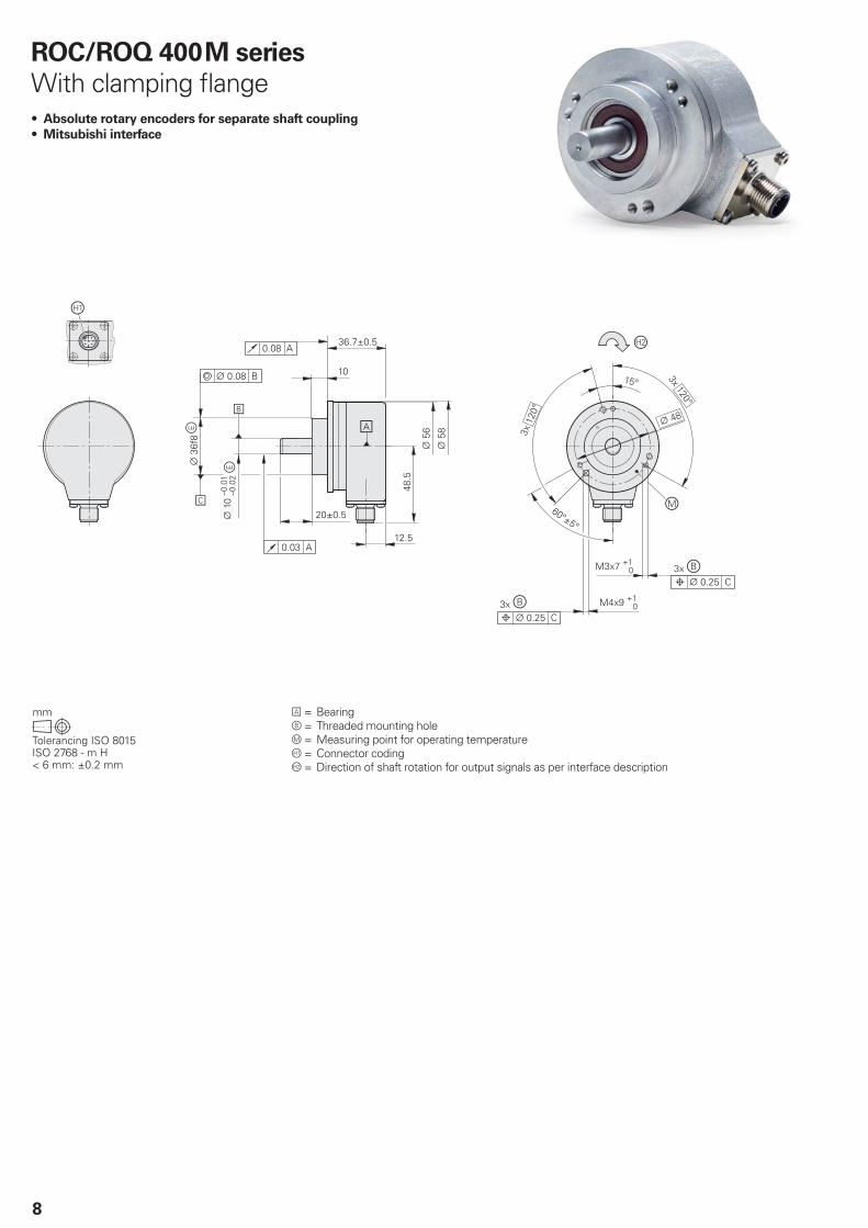
=Bearing=Threaded mounting hole = Measuring point for operating temperature = Connector coding=Directionofshaft rotationforoutput signals as per interface description
ROC/ROQ 400 M series
With clamping fl ange• Absolute rotary encoders for separate shaft coupling
• Mitsubishi interface

9
Absolute
Singleturn Multiturn
ROC 425 M ROQ 435 M
Absolute position values Mitsubishi
Ordering designation Mit03-4
Positions per revolution 33 554 432 (25 bits) 8 388 608 (23 bits)
Revolutions – 4 096
Code Pure binary
Elec. permissible speed 15 000 min–1 for continuous position value
Calculation time tcal 5 µs
System accuracy ± 20“
Electrical connection M12 fl ange socket (male) 8-pin, radial
Cable length 30 m
Voltage supply 3.6 V to 14 V DC
Power consumption (max.) 5 V: 700 mW14 V: 800 mW
5 V: 750 mW14 V: 850 mW
Current consumption (typical) 5 V: 90 mA (without load) 5 V: 100 mA (without load)
Shaft Solid shaft D = 10 mm
Mech. permiss. speed n1) 15 000 min–1 12 000 min–1
Starting torque 0.01 Nm (at 20 °C)
Moment of inertia of rotor 2.9 · 10–6 kgm2
Shaft load Axial: 40 NRadial: 60 N at shaft end
Vibration 55 to 2 000 HzShock 6 ms
300 m/s2 (EN 60 068-2-6) 2 000 m/s2 (EN 60 068-2-27)
Max. operating temp. 1) 100 °C
Min. operating temp. –30 °C
Protection EN 60 529 At housing: IP 67 At shaft inlet: IP 64 (IP 66 available on request)
Weight Approx. 0.35 kg
1) For the correlation between the operating temperature and the shaft speed or supply voltage, see General Mechanical Information in the Rotary Encoders catalog.

10
Interfaces
Mitsubishi pin layout
Mitsubishi pin layout
HEIDENHAIN encoders with the code letter M after the model designation are suited for connection to Mitsubishi controls withMitsubishi high speed interface
• Ordering designation: Mitsu01 Two-pair transmission
10-pin Mitsubishi
connector
20-pin Mitsubishi
connector
8-pin fl ange socket,
M12
Voltage supply Position values
10-pin 1 – 2 – 7 8 3 4
20-pin 20 19 1 11 6 16 7 17
8 2 5 1 3 4 7 6
UP Sensor
UP
0 V Sensor
0 VSerial Data Serial Data Request
Frame
Request
Frame
Brown/Green Blue White/Green White Gray Pink Violet Yellow
Cable shield connected to housing; UP = Power supply voltageSensor: The sensor line is connected in the encoder with the corresponding power line.Vacant pins or wires must not be used!
• Ordering designation: Mit02-4 Generation 1, two-pair transmission
• Ordering designation: Mit02-2 Generation 1, one-pair transmission
• Ordering designation: Mit03-4 Generation 2, two-pair transmission

11
Mitsubishi connecting cables
Cable Mitsubishi
PUR connecting cable for M12 connecting elements
[(1 x 4 x 0.14 mm2) + (4 x 0.34 mm2)]; AV = 0.34 mm2
Complete
With 8-pin M12 connector (female) and20-pin Mitsubishi connector
6 mm 646806-xx
Complete
With 8-pin M12 connector (female) and10-pin Mitsubishi connector
6 mm 647314-xx
AP: Cross section of power supply lines
PUR connecting cable [4 × 2 × 0.09 mm2]; AP = 0.09 mm2
PUR connecting cable [(4 × 0.14 mm2) + (4 × 0.34 mm2)]; AP = 0.34 mm2 6 mm 3.7 mm
Complete
With M12 connector (female) and M12 coupling (male), 8 pins each
368330-xx 801142-xx1)
Complete
With M12 right-angle connector (female) and M12 coupling (male), 8 pins each
373289-xx 801149-xx1)
With one connector
With 8-pin M12 connector (female)634265-xx –
With one connector
With 8-pin M12 right-angle connector (female)
606317-xx –
1) Maximum cable length 6 mAP: Cross section of power supply lines
Mitsubishi10-pin
Mitsubishi20-pin

������������ ��� ��������������� ��������������������������������������� �������������� ������������������ ��!�"����������
������ !���� ��!�
1102888 · 00 · A · 02 · 6/2014 · PDF
This Product Overview supersedes all previous editions, which thereby become invalid. The basis for ordering from HEIDENHAIN is always the Product Overview valid when the contract is made.
Further Information
• Catalog: Rotary Encoders• Catalog: Interfaces