ROTARY DRILLING BITS This chapter covers the … bits.pdfROTARY DRILLING BITS This chapter covers...
17
1 ROTARY DRILLING BITS This chapter covers the following items Roller cone bits The three cone bits • Principle features • Design factors • Rock bit classifications Poly diamond compact (PDC) bits Diamond bits Bit selection Bit dullness Well bit record and geological information Introduction Drilling bit represents the heart of drill string Proper selection is required It crushes the rock under the action of WOB and RPM Chippings are flushed away with mud The process results in a drill hole Roller cone bits Employs cones rotates about their own axis Used in mining and civil engineering First used in 1920 Cones can be milled teeth cut from the body or tungsten carbide buttons interested into the cones There are three types: • Two cone bit, milled tooth used for soft formation • Three cone bit most widely used, milled or insert • Four cone bit, milled tooth used for drilling large diameter 26 in (660.4 mm) Three cone bit principle features Three cutting cones, each fitted on a leg with suitable bearing Legs are welded together to form the cylindrical section
Transcript of ROTARY DRILLING BITS This chapter covers the … bits.pdfROTARY DRILLING BITS This chapter covers...
1
ROTARY DRILLING BITS
This chapter covers the following items
Roller cone bits The three cone bits
• Principle features • Design factors • Rock bit classifications
Poly diamond compact (PDC) bits Diamond bits Bit selection Bit dullness Well bit record and geological information
Introduction
Drilling bit represents the heart of drill string Proper selection is required It crushes the rock under the action of WOB and RPM Chippings are flushed away with mud The process results in a drill hole
Roller cone bits
Employs cones rotates about their own axis Used in mining and civil engineering First used in 1920 Cones can be milled teeth cut from the body or tungsten carbide buttons interested into the cones
There are three types: • Two cone bit, milled tooth used for soft formation • Three cone bit most widely used, milled or insert • Four cone bit, milled tooth used for drilling large diameter
26 in (660.4 mm) Three cone bit principle features
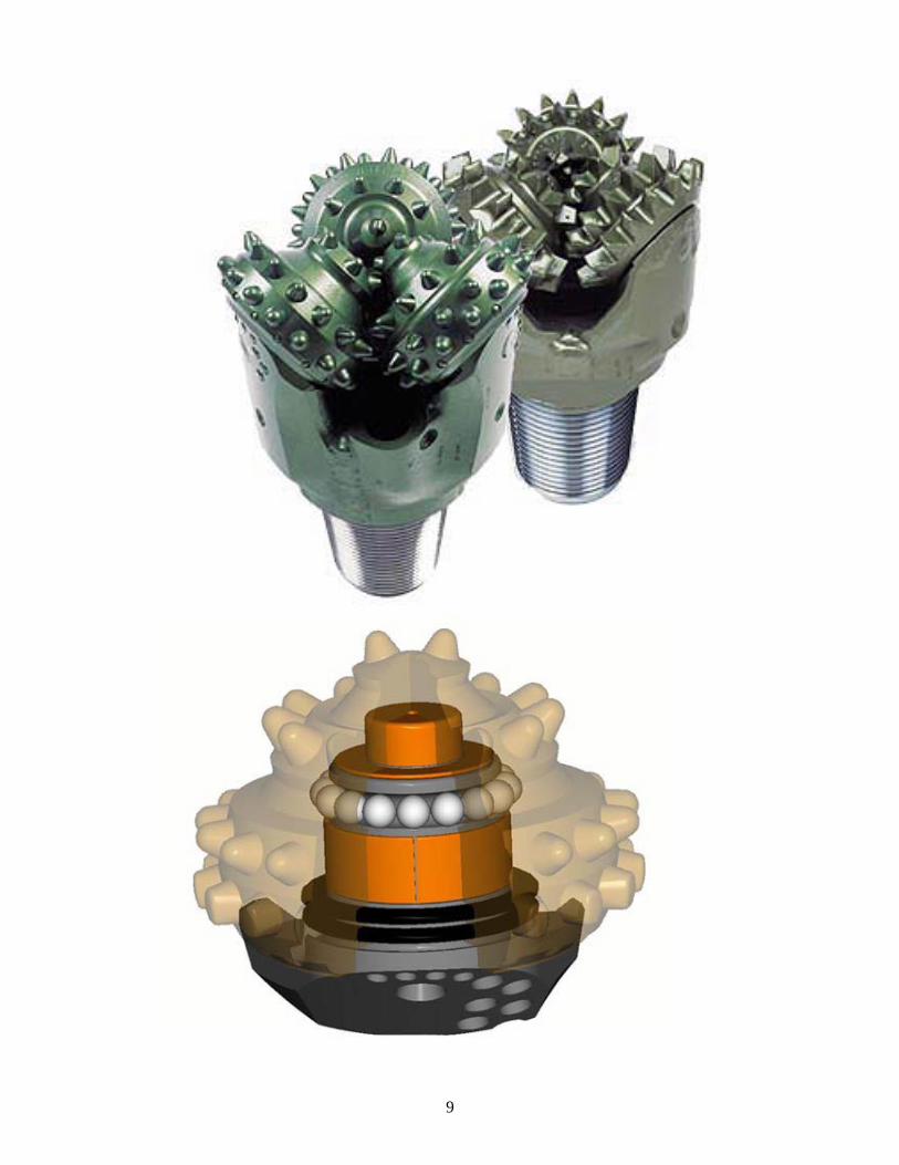
Three cutting cones, each fitted on a leg with suitable bearing Legs are welded together to form the cylindrical section
2
Section is threaded to make bin Each leg provided with an openings that can be reduced with a nozzle to give high jetting fluid velocity
Factors influencing the design are: type and hardness of formation and size of drilled hole
Formation hardness dictated the manufacture materials High content of nickel steel with molybdenum is used
Design factors
Bit design depend on formation properties and hole size Legs are same but cutters are different Three logs should be equally loaded The main design factors are Journal bearing, amount of offset, teeth, bearing and relationship between teeth and bearing
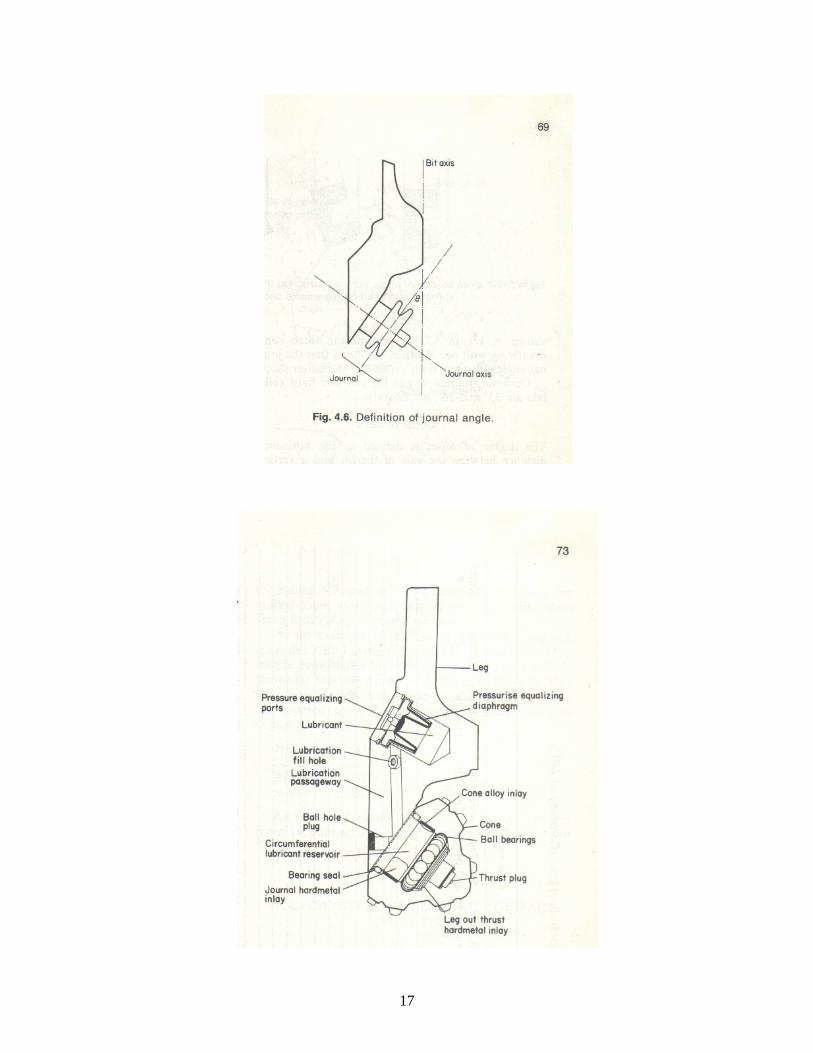
Journal bearing
The bearing load carrying surface Journal angle is the angle formed by a line perpendicular to the axis of the journal and the axis of the bit
Magnitude affect the size of the cone Increase in angle decrease cone size The smaller the angle the greater the gouging and scraping action
Optimum journal angle for soft and hard rock bits are 33 and 36 Cone offset
The degree of offset is defined as the horizontal distance between the axis of the bit and a vertical plane through the axis of the journal
It forces the cone to rotate around the axis of the bit The cone slips as it rotates causing tearing and gouging action Amount of offset directly relates to the strength of drilled rock Large offset used for soft formation Hard brittle rock need no offset Medium hard rock need up to 2 offset
Teeth
Length and geometry relate the rock strength Size of the cone and bearing structure affect the teeth
3
Teeth design criteria are: Spacing and interfitting of teeth governed by tooth strength, depth and included angle
Shape and length, dictated by formation characteristics Types of teeth, milled or inserted
Log slider and widely spaced teeth used for soft rock Long teeth allow results in breaking greater volume Wide spacing allows easy removal of drilled cuttings The included angle for soft rock from 39 to 42 Medium hard would have a moderate number of teeth and 43 to 45 included angle
Hard rocks need 45 to 50 included angle Milled teeth are faced with hardening metal to reduce wear Milled tooth bits are suitable for soft formation Insert are used for hard formation There are several types of insert to suit the hardness Chisel-shaped for soft rock Round or spherical for medium and hard rocks
Bearings
Functions: • Support radial load • Support thrust or axial loads • Secure the cone on the leg
Supporting loads is achieved by outer and nose bearing Ball and friction bearings secure the cone on the leg Two different bearing are available: antifriction and friction
Antifriction bearings or roller are two types: Roller-ball-roller (RBR), and roller-ball-friction
RBR, nose roller; intermediate ball; and outer roller The ball secure the cone Size influenced by journal angle and cone size RBR suffers from spalling of the races of the pin RBR bit have short life Normally used with bit with diameter greater than 12.25 in with adequate space and in situation where high rotary speed is required
4
Roller-ball-friction (RBF) Friction type bearing at the nose The inner ball and outer roller as the same as RBR The friction consists of a special case-harden bushing pressed into the nose of the cone
Introduced to overcome the shortcomings of RBR Allow thicker cone section Larger pin diameter Common for bit sizes up to 12.25 in
Friction bearing
Nose and outer bearing replaced by friction bearing Bearing lubrication
Bearing classified as sealed or non sealed Non sealed are lubricated by mud system through the face where the cone meets the journal
Sealed are lubricated by custom made system built within the leg body
Lubrication by mud is generally recommended Sealed bearing consists of bearing, seal, reservoir and pressure compensator
The seal is an O-ring type placed at the contact between the cone and the bearing lowermost point
The reservoir provides lubricants (special grease) to the bearing through a passageway in the leg
Pressure compensator has a flexible diaphragm operates within a metal protector
Maintains equal pressure inside and outside bearings Equipped with a pressure relief valve It protect the bearing seal when heat cause breakdown of grease into gaseous components
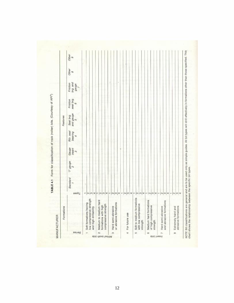
Rock bit classifications
IADC prepared a comparison chart, in 1972 Each bit is design by three code system
5
First code classifies the cutting structure, 1-3 for teeth soft, medium and hard, 5-8 for insert, soft medium hard semi abrasive, extremely hard and abrasive, 4 for future
Soft rock require long, slim and widely spaced teeth Medium requires short and less widely teeth Hard requires very short and closely spaced teeth Code 2 relates to formation hardness with division from 1to 4 from softest to hardest
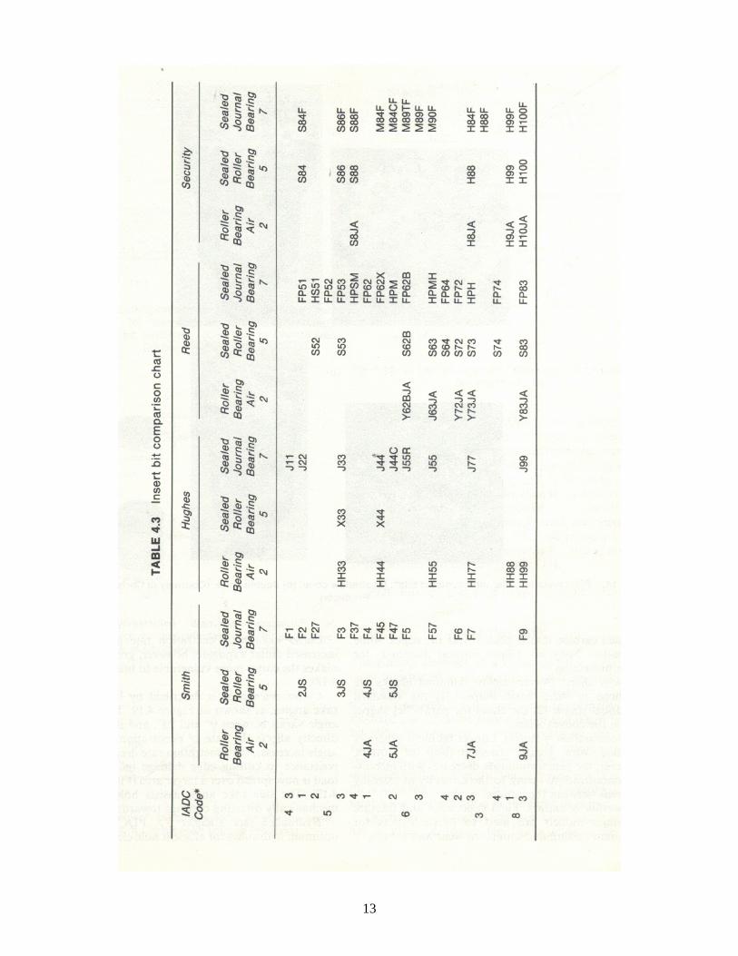
Code 3 for mechanical features of the bit, sealed non-sealed etc Major bit companies are Hughes, Security, Reed, and Smith Each company give there tables with IADC specifications
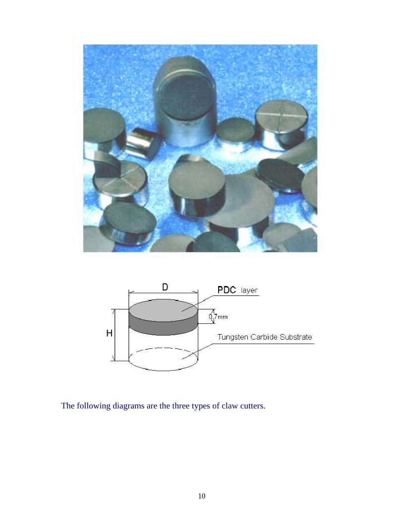
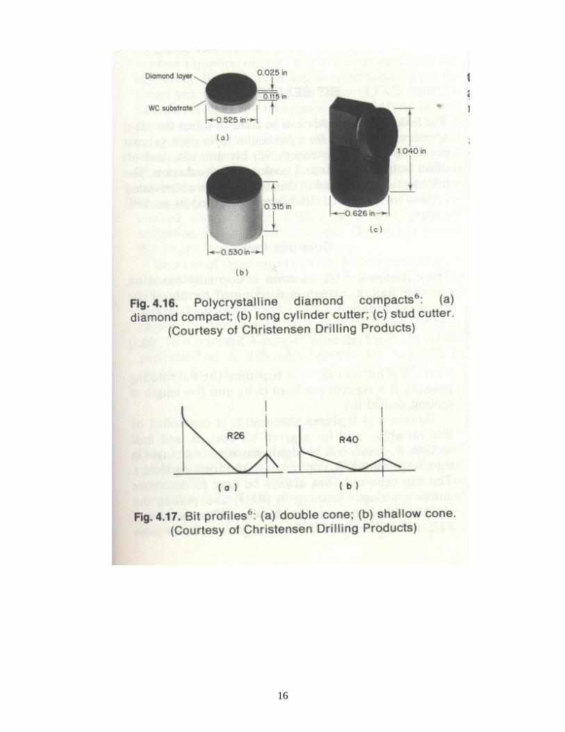
Polycrystalline Diamond Compact (PDC) bits
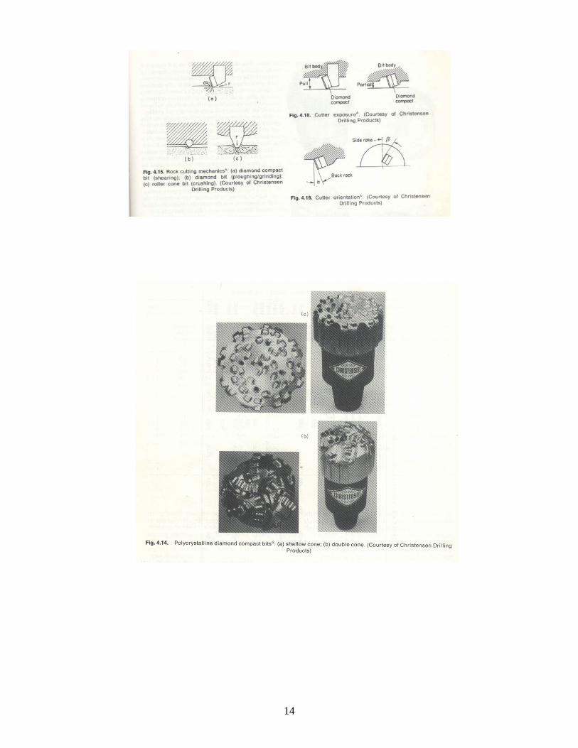
A new generation of old drag, fishtail bit Have no moving parts or bearings Break the rock in shear and no compression (ploughing /grinding action) as in diamond bits
Breaking in shear need less energy than in compression Less weight in bit, less wear and tear on rig and drill string Applied for soft to medium hard rock Employs large number of cutting called a drill blank The blank is made by bonding a layer of polydiamond crystalline (man made diamond) to a cemented tungsten carbide substrate in high pressure high temperature process
The blanks are bonded to a specially shaped tungsten carbide studs and then attached to the bit
During drilling the compact provides a continuous sharp cutting edge
PDC design influenced by nine factors: body materials, bit profile, gauge protection, cutter shape, number of cutters, cutter shape, cutter exposure, cutter orientation, and hydraulics
Bit body materials: two are available; heat-treated alloy steel used in roller cone bits and tungsten carbide matrix used in natural diamond
Steel body is less durable and less resistance to erosion Tungsten carbide manufactured as natural diamond Allow more complex profile Bond between crystals and body destroyed at 750 C
6
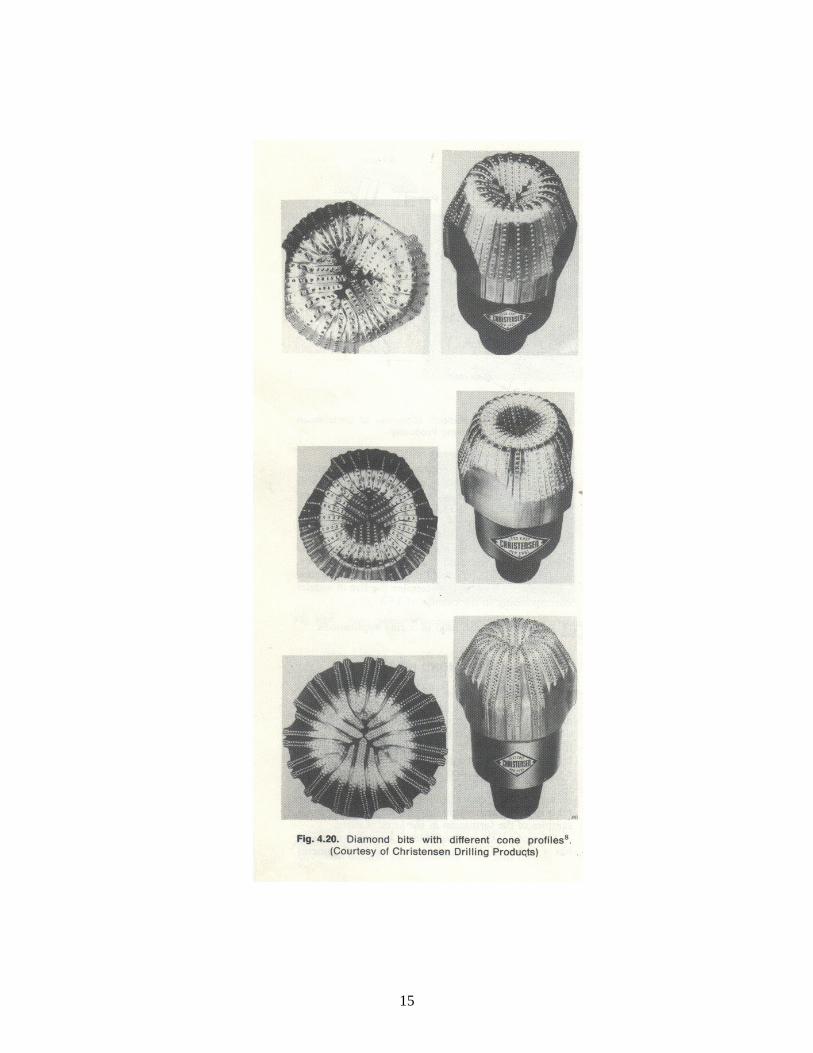
Bit profile affects cleaning and stability of the hole and gauge protection
Two are common: double cone allows more cutters, shallow cone affords less area of cleaning
Gauge protection: in steel body, tungsten carbide inserts placed near the edge: matrix body bit utilizes natural diamond for gauge protection.
Nowadays compact is fixed for gauge protection Cutter shape: three basic shapes; standard cylindrical, chisel or parabolic, and convex
Cutter concentration: field experience and fracture mechanics models used to locate cutters for maximum cutting and minimum wear and torque
Cutter exposure: its increases gives higher penetration rate Cutter orientation: described by back and side rake angle Back rake between 0 and 25 Penetration rate decreases with back rake increase, but resistance to cutting edge damage increases
Side rake assist hole cleaning by directing cutting towards the annulus
Hydraulics: PDC bits require optimum hydraulic for hole cleaning
More than three nozzles are mounted in the bit Nozzles may not be round and determined by total flow area (TFA)
TFA determines the size of nozzles according to manufacturers’ chart
PDC bits are also used in coring Diamond bits
The cutting elements are large number of small-sized diamonds geometrically distributed across a tungsten carbide body
No moving parts Used for hard and abrasive rocks when long bit run is required Used in deep and offshore wells where rig cost is very high Used for drilling and coring Diamond is the hardest metal with the highest thermal conductivity
7
Heat dissipated quickly from the cutting parts protecting diamond loss
Size of diamond determine the type of rock Large diamond for soft rocks and small-sized for hard Majority of diamond bits used for coring
Bit selection
Four methods are available: cost per foot, specific energy, bit dullness, and offset wells bit record
Cost per foot
The following equation is used:
( )B T t RC F+ += $/ft
B = bit cost $ T = trip time, hrs t = drilling time, hrs R = rig cost $/hr F = footage drilled , ft
Equation controlled by five variable These factors have uncertainties in calculations Cost per foot is plotted against time Cost decreases with time and start to increase again Lowest cost is used to pull bit out of hole Because of uncertainties, pulling out of bit on the evidence of one value may prove to be premature
C and IC should be applied Specific energy (SE)
Energy required to remove unit volume (SE) Derived as:
.2 .E W R Nπ= in.lb
W = weight on bit, lb N = rotary speed, rpm
8
R = bit radius
2( ).V R PRπ= in3
SE = E/V
..20 . tW NSE D F= in.lb/in3
.2.35 .W NSE D PR= Mj/m3
PR = penetration rate
..20 . tW NSE D F= in.lb/in3
For constant W and N and rock properties, high SE indicate low bit performance
Bit dullness
Degree of dullness can be used for proper selection Described by tooth and bearing Reported in 1/8 Coded in a form T1 to T8 and B1 to B8 T1 indicated 1/8 of teeth has gone B8 indicates that bearing life has gone With grading and coding bit can be properly selected Bit diameter shows in gauge or out of gauge hole Other grading records broken teeth, lost cones, eroded cones, …. Etc.
Well bit record and geological information
Offset wells and geological information can provide useful guides for the selection
Sonic logs can be used to provide an estimate of rock strength
9
10
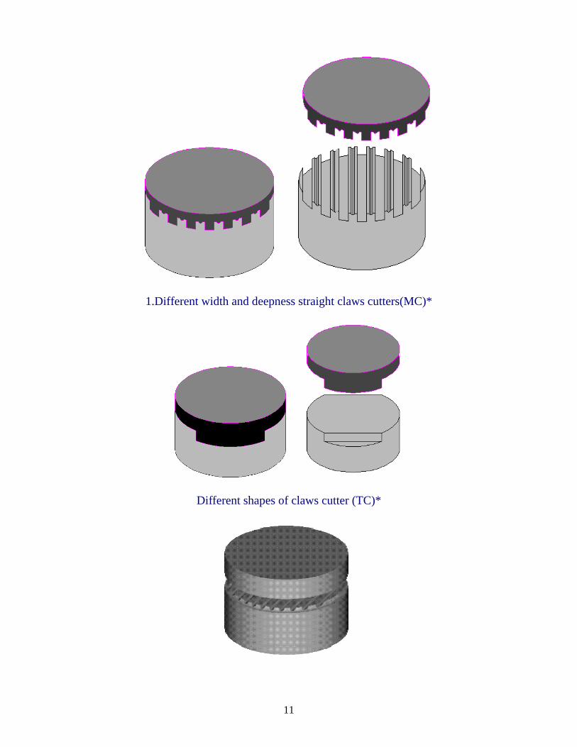
The following diagrams are the three types of claw cutters.
11
1.Different width and deepness straight claws cutters(MC)*
Different shapes of claws cutter (TC)*
12
13
14
15
16
17