
Rolling processes - AL-Mustansiriyah...
12
Page1 Rolling processes 5-1 introduction: Rolling is the process of reducing the thickness or changing the cross section of a long workpiece by compressive forces applied through a set of rolls, as shown in figure (5-1). Fig. (5-1) Most rolling is carried out by hot working, called hot rolling, owing to the large amount of deformation required. Hot-rolled metal is generally free of residual stresses, and its properties are isotropic. Disadvantages of hot rolling are that the product cannot be held to close tolerances, and the surface has a characteristic oxide scale. Steelmaking provides the most common application of rolling operations. Figure (5-2) illustrates the sequence of steps in a steel rolling mill to show the variety of products made. Similar steps occur in other basic metal industries. The work starts out as a cast steel ingot that has just solidified. While it is still hot, the ingot is placed in a furnace where it remains for many hours until it has reached a uniform temperature throughout, so that the metal will flow consistently during rolling. For steel, the desired temperature for rolling is around 1200_C (2200_F). The heating operation is called soaking, and the furnaces in which it is carried out are called soaking pits. From soaking, the ingot is moved to the rolling mill, where it is rolled into one of three intermediate shapes called blooms, billets, or slabs, as shown in figure (5-2).
-
Upload
duongthuan -
Category
Documents
-
view
228 -
download
4
Transcript of Rolling processes - AL-Mustansiriyah...

Pag
e1
Rolling processes
5-1 introduction: Rolling is the process of reducing the thickness or changing the cross section of a long workpiece by compressive forces applied through a set of rolls, as shown in figure (5-1).
Fig. (5-1)
Most rolling is carried out by hot working, called hot rolling, owing to the large amount of deformation required. Hot-rolled metal is generally free of residual stresses, and its properties are isotropic. Disadvantages of hot rolling are that the product cannot be held to close tolerances, and the surface has a characteristic oxide scale.
Steelmaking provides the most common application of rolling operations. Figure (5-2) illustrates the sequence of steps in a steel rolling mill to show the variety of products made. Similar steps occur in other basic metal industries. The work starts out as a cast steel ingot that has just solidified. While it is still hot, the ingot is placed in a furnace where it remains for many hours until it has reached a uniform temperature throughout, so that the metal will flow consistently during rolling. For steel, the desired temperature for rolling is around 1200_C (2200_F). The heating operation is called soaking, and the furnaces in which it is carried out are called soaking pits. From soaking, the ingot is moved to the rolling mill, where it is rolled into one of three intermediate shapes called blooms, billets, or slabs, as shown in figure (5-2).

Pag
e2
Fig. (5-2)
5.2 Flat rolling and its analysis: Flat rolling is illustrated in Figures (5-1). It involves the rolling of slabs, strips, sheets, and plates workparts of rectangular cross section in which the width is greater than the thickness. In flat rolling, the work is squeezed between two rolls so that its thickness is reduced by an amount called the draft:
=2R (1-cosα) 5.1
Where d = draft, mm (in); = starting thickness, mm (in); and = final
thickness, mm (in).R = roll radius in mm and (α) = bite angle in degree. Draft is sometimes expressed as a fraction of the starting stock thickness, called the reduction
5.2
Where r = reduction. When a series of rolling operations are used, reduction is taken as the sum of the drafts divided by the original thickness. In addition to
(Cross sectional
area > 40x40 mm2).
(Cross sectional
area > 230 cm2).
(Cross sectional area > 100 cm2 and
with a width ≥ 2 x thickness).
Thickness > 6 mm
Thickness <6 mm and
width < 600 mm
Pag
e3
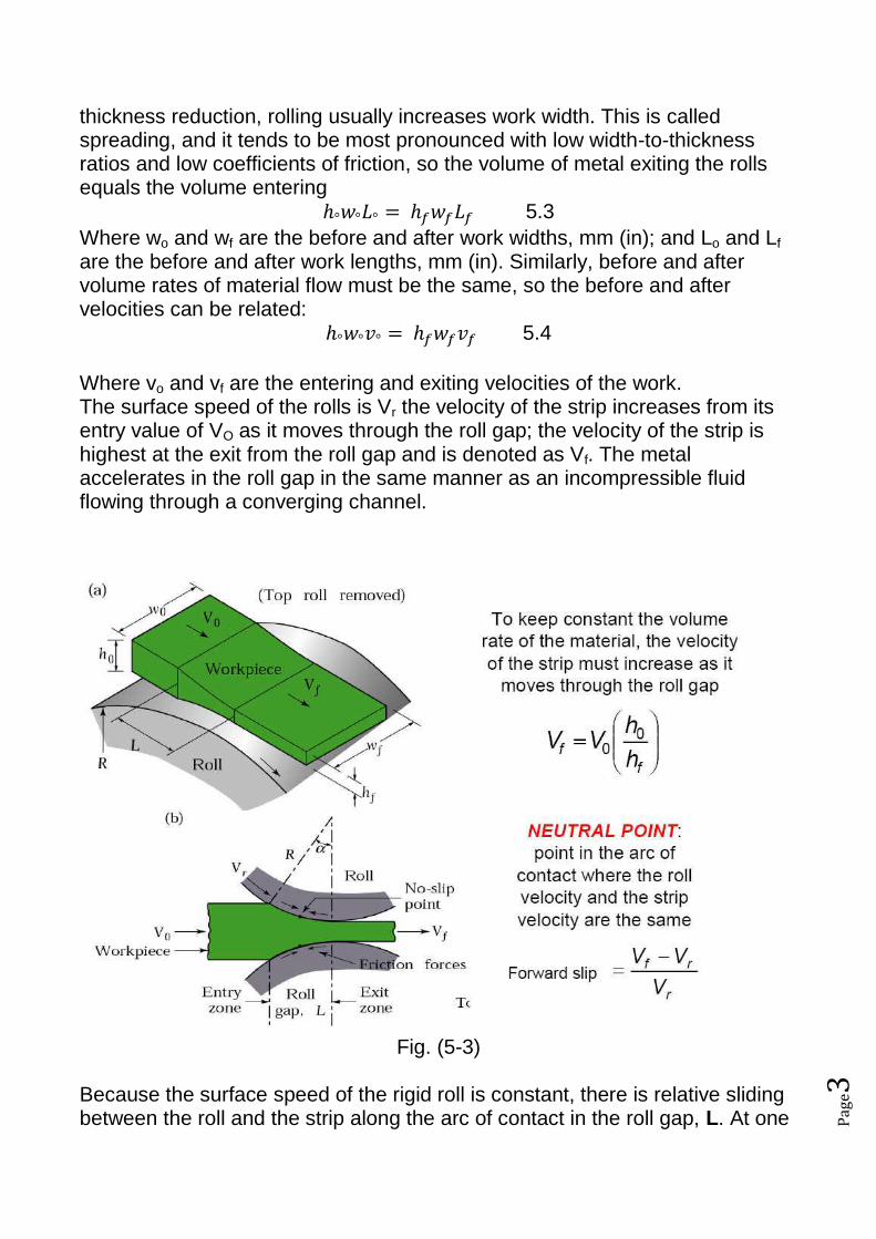
thickness reduction, rolling usually increases work width. This is called spreading, and it tends to be most pronounced with low width-to-thickness ratios and low coefficients of friction, so the volume of metal exiting the rolls equals the volume entering
5.3
Where wo and wf are the before and after work widths, mm (in); and Lo and Lf are the before and after work lengths, mm (in). Similarly, before and after volume rates of material flow must be the same, so the before and after velocities can be related:
5.4
Where vo and vf are the entering and exiting velocities of the work. The surface speed of the rolls is Vr the velocity of the strip increases from its entry value of VO as it moves through the roll gap; the velocity of the strip is highest at the exit from the roll gap and is denoted as Vf. The metal accelerates in the roll gap in the same manner as an incompressible fluid flowing through a converging channel.
Fig. (5-3) Because the surface speed of the rigid roll is constant, there is relative sliding between the roll and the strip along the arc of contact in the roll gap, L. At one
Pag
e4
point along the contact length (called the neutral point or no-slip point) the velocity of the strip is the same as that of the roll. To the left of this point, the roll moves faster than the strip; to the right of this point, the strip moves faster than the roll. Consequently, the frictional forces-which oppose motion between two sliding bodies-act on the strip as shown above. On either side of this point, slipping and friction occur between roll and work. The amount of slip between the rolls and the work can be measured by means of the forward slip, a term used in rolling that is defined:
5.5
Where s = forward slip; vf = final (exiting) work velocity, m/s (ft/sec); and vr =
roll speed, m/s (ft/sec). The rolls pull the material into the roll gap through a net frictional force on the material. Thus, the net frictional force must be to the right in Fig. (5-3 b). This also means that the frictional force to the left of the neutral point must be higher than the friction force to the right. Although friction is necessary for rolling materials (just as it is in driving a car on a road), energy is dissipated in overcoming friction. Thus, increasing friction also increases rolling forces and power requirements. Thus, a compromise is made in practice: Low and controlled friction is induced in rolling through the use of effective lubricants. The maximum possible draft is defined as in equation below; it can be shown that this quantity is a function of the roll radius, R, and the coefficient of friction, μ, between the strip and the roll by the following relationship:
dmax 5.6
Thus, as expected, the higher the friction and the larger the roll radius, the greater the maximum possible draft becomes. Note that this situation is similar to the use of large tires (high R) and rough treads (high, μ.) on farm tractors and off-road earthmoving equipment, thus permitting the vehicles to travel over rough terrain without skidding. Coefficient of friction in rolling depends on lubrication, work material, and working temperature. In cold rolling, the value is around 0.1; in warm working, a typical value is around 0.2; and in hot rolling, m is around 0.4. Hot rolling is often characterized by a condition called sticking, in which the hot work surface adheres to the rolls over the contact arc. This condition often occurs in the rolling of steels and high-temperature alloys. When sticking occurs, the coefficient of friction can be as high as 0.7. The consequence of sticking is that the surface layers of the work are restricted to move at the same speed as the roll speed vr; and below the surface, deformation is more severe in order to allow passage of the piece through the roll gap.
Pag
e5
The true strain experienced by the work in rolling is based on before and after stock thicknesses. In equation form,
5.7
The true strain can be used to determine the average flow stress Yf applied to the work material in flat rolling. Recall from eq. (4.3)
5.8
The minimum number of passes= h◦-hf/dmax
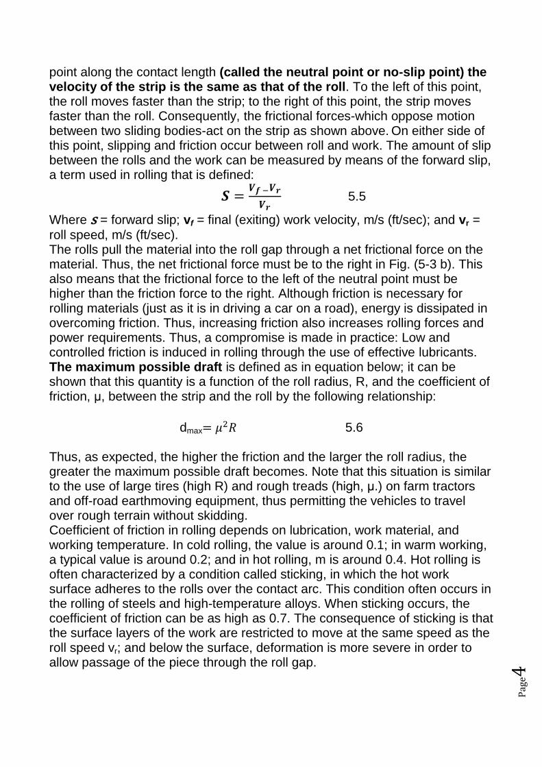
5.3 roll force, torque, and power requirements: The rolls apply pressure on the flat strip in order to reduce its thickness, resulting in a roll force, F, as shown in Fig. 5-4.
Fig. 5-4 Note that this force appears in the figure as perpendicular to the plane of the strip, rather than at an angle. This is because, in practice, the arc of contact is very small compared with the roll radius, so we can assume that the roll force is perpendicular to the strip without causing significant error in calculations. The roll force in flat rolling can be estimated from the formula
5.9
(For a frictionless situation; however, an estimate of the actual roll force, including friction, may be made by increasing this calculated force by about
20%). Where = average flow stress from Eq. (5.8), MPa (lb/in2); and the
product (wL) is the roll-work contact area, mm2 (in2). Contact length can be approximated by
L= 5.10
The torque in rolling can be estimated by assuming that the roll force is centered on the work as it passes between the rolls, and that it acts with a moment arm of one-half the contact length L. Thus, torque for each roll is
Torque
Pag
e6
T=0.5FL 5.11 The power required per roll can be estimated by assuming that (F) acts in the middle of the arc of contact; thus, in Fig. (5-4), a = L/2. Therefore, the total power (for two rolls), in S.I. units, is
Power (in Kw) =
5.12
Where F is in newtons , L is in meters, and N is the revolutions per minute of the roll. In traditional English units, the total power can be expressed as
Power (in hp) =
5.13
Where F is in pounds and L is in feet. Example: A 300-mm-wide strip 25-mm thick is fed through a rolling mill with two powered rolls each of radius = 250 mm. The work thickness is to be reduced to 22 mm in one pass at a roll speed of 50 rev/min. The work material has a flow curve defined by K = 275 MPa and n = 0.15, and the coefficient of friction between the rolls and the work is assumed to be 0.12. Determine if the friction is sufficient to permit the rolling operation to be accomplished. If so, calculate the roll force, torque, and horsepower. Solution: The draft attempted in this rolling operation is
d = 25 - 22 = 3mm From equation (5.6) we can find the maximum draft
dmax = (0.12)2(250) = 3.6mm Since the maximum allowable draft exceeds the attempted reduction, the rolling operation is feasible. To compute rolling force, we need the contact length L and the average flow stress Yf . The contact length is given by Eq. (5.10)
L=
L=
=27.4 mm
Yf is determined from the true strain:
=0.128
=175.7 MPa
Rolling force is determined from Eq. (5.9)
Pag
e7
F =175.7(300) (27.4) =1. 444. 254 N Torque required to drive each roll is given by Eq. (5.11):
T = 0.5(1. 444.254) (27. 4) (10-3) = 19. 786 N-m And the power is obtained from Eq. (5.12):
Power (in Kw) =
= 207.284 Kw
(We note that one horsepower =745.7 W):→ Power in hp =
hp
It can be seen from this example that large forces and power are required in rolling. Inspection of Eqs. (5.9) and (5.12) indicates that force and/or power to roll a strip of a given width and work material can be reduced by any of the following: (1) using hot rolling rather than cold rolling to reduce strength and strain hardening (K and n) of the work material; (2) reducing the draft in each pass; (3) using a smaller roll radius R to reduce contact area and then reduce the force; and (4) using a lower rolling speed N to reduce power.
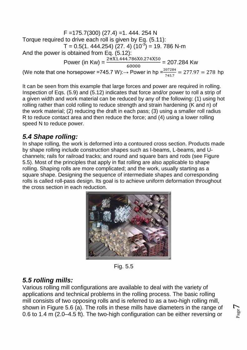
5.4 Shape rolling: In shape rolling, the work is deformed into a contoured cross section. Products made by shape rolling include construction shapes such as I-beams, L-beams, and U-channels; rails for railroad tracks; and round and square bars and rods (see Figure 5.5). Most of the principles that apply in flat rolling are also applicable to shape rolling. Shaping rolls are more complicated; and the work, usually starting as a square shape. Designing the sequence of intermediate shapes and corresponding rolls is called roll-pass design. Its goal is to achieve uniform deformation throughout the cross section in each reduction.
Fig. 5.5
5.5 rolling mills: Various rolling mill configurations are available to deal with the variety of applications and technical problems in the rolling process. The basic rolling mill consists of two opposing rolls and is referred to as a two-high rolling mill, shown in Figure 5.6 (a). The rolls in these mills have diameters in the range of 0.6 to 1.4 m (2.0–4.5 ft). The two-high configuration can be either reversing or

Pag
e8
nonreversing. In the nonreversing mill, the work always passes through from the same side. The reversing mill allows the direction of roll rotation to be reversed, so that the work can be passed through in either direction. This permits a series of reductions to be made through the same set of rolls, simply by passing through the work from opposite directions multiple times. The disadvantage of the reversing configuration is the significant angular momentum possessed by large rotating rolls and the associated technical problems involved in reversing the direction.
Fig (5.6) various configurations of rolling mills: (a) 2-high, (b) 3-high, (c) 4-high, (d) cluster mill, and (e) tandem rolling mill.
Several alternative arrangements are illustrated in Figure 5.6. In the three-high configuration, Figure 5.6 (b), there are three rolls in a vertical column, and the direction of rotation of each roll remains unchanged. To achieve a series of reductions, the work can be passed through from either side by raising or lowering the strip after each pass. The equipment in a three-high rolling mill becomes more complicated, because an elevator mechanism is needed to raise and lower the work. As several of the previous equations indicate, advantages are gained in reducing roll diameter. Roll-work contact length is reduced with a lower roll radius, and this leads to lower forces, torque, and power. The four-high rolling mill uses two smaller-diameter rolls to contact the work and two backing rolls behind them, as in Figure 5.6 (c). Owing to the high roll forces, these smaller rolls would deflect elastically between their end bearings as the work passes through unless the larger backing rolls were used to support them. Another roll configuration that allows smaller working rolls against the work is the cluster rolling mill (Figure 5.6(d)). To achieve higher throughput rates in standard products, a tandem rolling mill is often used. This configuration consists of a series of rolling stands, as represented in Figure 5.6(e). Although only three stands are shown in our

Pag
e9
sketch, a typical tandem rolling mill may have eight or ten stands, each making a reduction in thickness or a refinement in shape of the work passing through.
5.6Various Rolling Processes and Mills: Several other bulk deformation processes use rolls to form the workpart. The operations include thread rolling, ring rolling, and roll piercing….etc
5.6.1 Transverse rolling or Roll forging in this operation (also called cross rolling), the cross section of a round bar is shaped by passing it through a pair of rolls with profiled grooves (Fig. 5.7). Roll forging typically is used to produce tapered shafts and leaf springs, table knives, and hand tools; it also may be used as a preliminary forming operation, to be followed by other forging processes.
Fig 5.7
5.6.2 Skew Rolling. A process similar to roll forging is skew rolling, typically used for making ball bearings (Fig. 5.8). Round wire or rod is fed into the roll gap, and roughly spherical blanks are formed continuously by the action of the rotating rolls.
Fig 5.8
Pag
e10
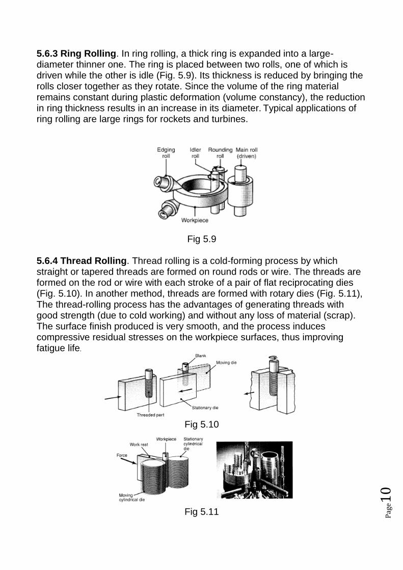
5.6.3 Ring Rolling. In ring rolling, a thick ring is expanded into a large-diameter thinner one. The ring is placed between two rolls, one of which is driven while the other is idle (Fig. 5.9). Its thickness is reduced by bringing the rolls closer together as they rotate. Since the volume of the ring material remains constant during plastic deformation (volume constancy), the reduction in ring thickness results in an increase in its diameter. Typical applications of ring rolling are large rings for rockets and turbines.
Fig 5.9 5.6.4 Thread Rolling. Thread rolling is a cold-forming process by which straight or tapered threads are formed on round rods or wire. The threads are formed on the rod or wire with each stroke of a pair of flat reciprocating dies (Fig. 5.10). In another method, threads are formed with rotary dies (Fig. 5.11), The thread-rolling process has the advantages of generating threads with good strength (due to cold working) and without any loss of material (scrap). The surface finish produced is very smooth, and the process induces compressive residual stresses on the workpiece surfaces, thus improving fatigue life.
Fig 5.10
Fig 5.11
Pag
e11
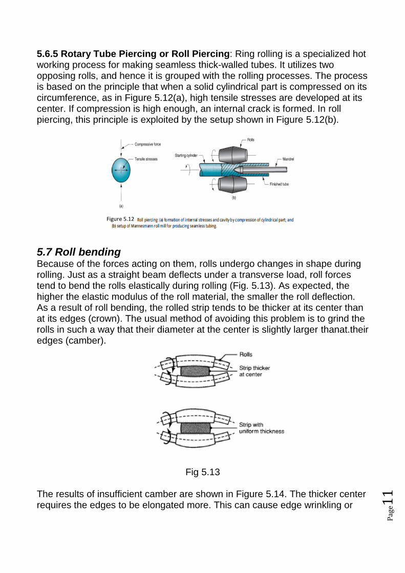
5.6.5 Rotary Tube Piercing or Roll Piercing: Ring rolling is a specialized hot working process for making seamless thick-walled tubes. It utilizes two opposing rolls, and hence it is grouped with the rolling processes. The process is based on the principle that when a solid cylindrical part is compressed on its circumference, as in Figure 5.12(a), high tensile stresses are developed at its center. If compression is high enough, an internal crack is formed. In roll piercing, this principle is exploited by the setup shown in Figure 5.12(b).
5.7 Roll bending Because of the forces acting on them, rolls undergo changes in shape during rolling. Just as a straight beam deflects under a transverse load, roll forces tend to bend the rolls elastically during rolling (Fig. 5.13). As expected, the higher the elastic modulus of the roll material, the smaller the roll deflection. As a result of roll bending, the rolled strip tends to be thicker at its center than at its edges (crown). The usual method of avoiding this problem is to grind the rolls in such a way that their diameter at the center is slightly larger thanat.their edges (camber).
Fig 5.13
The results of insufficient camber are shown in Figure 5.14. The thicker center requires the edges to be elongated more. This can cause edge wrinkling or
Figure 5.12

Pag
e12
warping of a plate. The center is left in residual tension and center cracking can occur. Fig 5.14 Possible effects of insufficient camber (a): edge wrinkling (b), warping (c), centerline cracking (d), and (e) residual stresses.
If the rolls are over-cambered, as shown in Figure 5.15, the residual stress pattern is the opposite. Centerline compression and edge tension may cause edge cracking, lengthwise splitting, and a wavy center. Fig 5.15Effects of over-cambering (a): wavy center (b), centerline splitting (c), edge cracking (d),
and (e) residual stresses.