Rockwell Automation Library of Logix Objects Reference...
96
Rockwell Automation Library of Logix Diagnostic Objects Version 3.5 Reference Manual
Transcript of Rockwell Automation Library of Logix Objects Reference...
Rockwell Automation Library of Logix Diagnostic ObjectsVersion 3.5
Reference Manual
Important User Information
Read this document and the documents listed in the additional resources section about installation, configuration, and operation of this equipment before you install, configure, operate, or maintain this product. Users are required to familiarize themselves with installation and wiring instructions in addition to requirements of all applicable codes, laws, and standards.
Activities including installation, adjustments, putting into service, use, assembly, disassembly, and maintenance are required to be carried out by suitably trained personnel in accordance with applicable code of practice.
If this equipment is used in a manner not specified by the manufacturer, the protection provided by the equipment may be impaired.
In no event will Rockwell Automation, Inc. be responsible or liable for indirect or consequential damages resulting from the use or application of this equipment.
The examples and diagrams in this manual are included solely for illustrative purposes. Because of the many variables and requirements associated with any particular installation, Rockwell Automation, Inc. cannot assume responsibility or liability for actual use based on the examples and diagrams.
No patent liability is assumed by Rockwell Automation, Inc. with respect to use of information, circuits, equipment, or software described in this manual.
Reproduction of the contents of this manual, in whole or in part, without written permission of Rockwell Automation, Inc., is prohibited.
Throughout this manual, when necessary, we use notes to make you aware of safety considerations.
Labels may also be on or inside the equipment to provide specific precautions.
Allen-Bradley, Rockwell Software, Rockwell Automation, RSLogix, RSLinx, Logix5000, SoftLogix, FactoryTalk, PlantPAx, and ControlLogix are trademarks of Rockwell Automation, Inc.
Trademarks not belonging to Rockwell Automation are property of their respective companies.
WARNING: Identifies information about practices or circumstances that may cause an explosion in a hazardous environment, which may lead to personal injury or death, property damage, or economic loss.
ATTENTION: Identifies information about practices or circumstances may lead to personal injury or death, property damage, or economic loss. Attentions help you identify a hazard, avoid a hazard, and recognize the consequence.
IMPORTANT Identifies information that is critical for successful application and understanding of the product.
SHOCK HAZARD: Labels may be on or inside the equipment, for example, a drive or motor, to alert people that dangerous voltage may be present.
BURN HAZARD: Labels may be on or inside the equipment, for example, a drive or motor, to alert people that surfaces may reach dangerous temperatures.
ARC FLASH HAZARD: Labels may be on or inside the equipment, for example, a motor control center, to alert people to potential Arc Flash. Arc Flash will cause severe injury or death. Wear proper Personal Protective Equipment (PPE). Follow ALL Regulatory requirements for safe work practices and for Personal Protective Equipment (PPE).
Table of Contents
Preface Software Compatibility and Content Revision. . . . . . . . . . . . . . . . . . . . . . . . 7Additional Resources . . . . . . . . . . . . . . . . . . . . . . . . . . . . . . . . . . . . . . . . . . . . . . . 8
Chapter 1Logix Change Detector (L_ChangeDet)
Guidelines . . . . . . . . . . . . . . . . . . . . . . . . . . . . . . . . . . . . . . . . . . . . . . . . . . . . . . . 10Functional Description . . . . . . . . . . . . . . . . . . . . . . . . . . . . . . . . . . . . . . . . . . . 10Required Files . . . . . . . . . . . . . . . . . . . . . . . . . . . . . . . . . . . . . . . . . . . . . . . . . . . 12Controller Code . . . . . . . . . . . . . . . . . . . . . . . . . . . . . . . . . . . . . . . . . . . . . . . . . 12
Logix Change Detector InOut Structure . . . . . . . . . . . . . . . . . . . . . . . 12Logix Change Detector Input Structure . . . . . . . . . . . . . . . . . . . . . . . . 13Logix Change Detector Output Structure . . . . . . . . . . . . . . . . . . . . . . 13Logix Change Detector Local Configuration Tags. . . . . . . . . . . . . . . 14
Operations . . . . . . . . . . . . . . . . . . . . . . . . . . . . . . . . . . . . . . . . . . . . . . . . . . . . . . 15Modes . . . . . . . . . . . . . . . . . . . . . . . . . . . . . . . . . . . . . . . . . . . . . . . . . . . . . . . 15Alarms . . . . . . . . . . . . . . . . . . . . . . . . . . . . . . . . . . . . . . . . . . . . . . . . . . . . . . 15Simulation . . . . . . . . . . . . . . . . . . . . . . . . . . . . . . . . . . . . . . . . . . . . . . . . . . . 15Execution. . . . . . . . . . . . . . . . . . . . . . . . . . . . . . . . . . . . . . . . . . . . . . . . . . . . 15
Programming Example . . . . . . . . . . . . . . . . . . . . . . . . . . . . . . . . . . . . . . . . . . . 16
Chapter 2Logix Controller CPU Utilization (L_CPU)
Guidelines . . . . . . . . . . . . . . . . . . . . . . . . . . . . . . . . . . . . . . . . . . . . . . . . . . . . . . . 20Functional Description . . . . . . . . . . . . . . . . . . . . . . . . . . . . . . . . . . . . . . . . . . . 21Required Files . . . . . . . . . . . . . . . . . . . . . . . . . . . . . . . . . . . . . . . . . . . . . . . . . . . 22
Controller Files . . . . . . . . . . . . . . . . . . . . . . . . . . . . . . . . . . . . . . . . . . . . . . 22Visualization Files . . . . . . . . . . . . . . . . . . . . . . . . . . . . . . . . . . . . . . . . . . . . 23
Controller Code . . . . . . . . . . . . . . . . . . . . . . . . . . . . . . . . . . . . . . . . . . . . . . . . . 24Logix Controller CPU Utilization InOut Structure . . . . . . . . . . . . . 24Logix Controller CPU Utilization Input Structure. . . . . . . . . . . . . . 25Logix Controller CPU Utilization Output Structure . . . . . . . . . . . . 26Logix Controller CPU Utilization Local Configuration Tags . . . . 26
Operations . . . . . . . . . . . . . . . . . . . . . . . . . . . . . . . . . . . . . . . . . . . . . . . . . . . . . . 27Modes . . . . . . . . . . . . . . . . . . . . . . . . . . . . . . . . . . . . . . . . . . . . . . . . . . . . . . . 27Alarms . . . . . . . . . . . . . . . . . . . . . . . . . . . . . . . . . . . . . . . . . . . . . . . . . . . . . . 27Simulation . . . . . . . . . . . . . . . . . . . . . . . . . . . . . . . . . . . . . . . . . . . . . . . . . . . 27Execution. . . . . . . . . . . . . . . . . . . . . . . . . . . . . . . . . . . . . . . . . . . . . . . . . . . . 27
Programming Example . . . . . . . . . . . . . . . . . . . . . . . . . . . . . . . . . . . . . . . . . . . 28Display Elements. . . . . . . . . . . . . . . . . . . . . . . . . . . . . . . . . . . . . . . . . . . . . . . . . 30
Status/Quality Indicators . . . . . . . . . . . . . . . . . . . . . . . . . . . . . . . . . . . . . 30Maintenance Bypass Indicator . . . . . . . . . . . . . . . . . . . . . . . . . . . . . . . . . 31Using Display Elements . . . . . . . . . . . . . . . . . . . . . . . . . . . . . . . . . . . . . . . 31
Faceplate . . . . . . . . . . . . . . . . . . . . . . . . . . . . . . . . . . . . . . . . . . . . . . . . . . . . . . . . 33Operator Tab . . . . . . . . . . . . . . . . . . . . . . . . . . . . . . . . . . . . . . . . . . . . . . . . 33Communications Tab . . . . . . . . . . . . . . . . . . . . . . . . . . . . . . . . . . . . . . . . 35CPU Usage Tab. . . . . . . . . . . . . . . . . . . . . . . . . . . . . . . . . . . . . . . . . . . . . . 36Memory Tab . . . . . . . . . . . . . . . . . . . . . . . . . . . . . . . . . . . . . . . . . . . . . . . . . 37
Rockwell Automation Publication PROCES-RM003D-EN-P - January 2016 3
Table of Contents
Connections Tab . . . . . . . . . . . . . . . . . . . . . . . . . . . . . . . . . . . . . . . . . . . . . 38Maintenance Tab . . . . . . . . . . . . . . . . . . . . . . . . . . . . . . . . . . . . . . . . . . . . . 39Logix CPU Faceplate Help . . . . . . . . . . . . . . . . . . . . . . . . . . . . . . . . . . . . 41
Chapter 3Logix Redundant Controller Monitor (L_Redun)
Guidelines . . . . . . . . . . . . . . . . . . . . . . . . . . . . . . . . . . . . . . . . . . . . . . . . . . . . . . . 43Functional Description . . . . . . . . . . . . . . . . . . . . . . . . . . . . . . . . . . . . . . . . . . . 44Required Files . . . . . . . . . . . . . . . . . . . . . . . . . . . . . . . . . . . . . . . . . . . . . . . . . . . . 44
Controller File . . . . . . . . . . . . . . . . . . . . . . . . . . . . . . . . . . . . . . . . . . . . . . . 44Visualization Files . . . . . . . . . . . . . . . . . . . . . . . . . . . . . . . . . . . . . . . . . . . . 45
Controller Code . . . . . . . . . . . . . . . . . . . . . . . . . . . . . . . . . . . . . . . . . . . . . . . . . 46Logix Redundant Controller Monitor InOut Structure . . . . . . . . . . 46Logix Redundant Controller Monitor Input Structure. . . . . . . . . . . 47Logix Redundant Controller Monitor Output Structure . . . . . . . . . 49Logix Redundant Controller Monitor Local Configuration Tags . 52
Operations. . . . . . . . . . . . . . . . . . . . . . . . . . . . . . . . . . . . . . . . . . . . . . . . . . . . . . . 52Modes . . . . . . . . . . . . . . . . . . . . . . . . . . . . . . . . . . . . . . . . . . . . . . . . . . . . . . . 53Alarm. . . . . . . . . . . . . . . . . . . . . . . . . . . . . . . . . . . . . . . . . . . . . . . . . . . . . . . . 53Simulation . . . . . . . . . . . . . . . . . . . . . . . . . . . . . . . . . . . . . . . . . . . . . . . . . . . 53Execution . . . . . . . . . . . . . . . . . . . . . . . . . . . . . . . . . . . . . . . . . . . . . . . . . . . . 53
Programming Example. . . . . . . . . . . . . . . . . . . . . . . . . . . . . . . . . . . . . . . . . . . . 54Display Elements . . . . . . . . . . . . . . . . . . . . . . . . . . . . . . . . . . . . . . . . . . . . . . . . . 55
Status/Quality Indicators . . . . . . . . . . . . . . . . . . . . . . . . . . . . . . . . . . . . . 56Using Display Elements . . . . . . . . . . . . . . . . . . . . . . . . . . . . . . . . . . . . . . . 57
Faceplate . . . . . . . . . . . . . . . . . . . . . . . . . . . . . . . . . . . . . . . . . . . . . . . . . . . . . . . . 58Operator Tab . . . . . . . . . . . . . . . . . . . . . . . . . . . . . . . . . . . . . . . . . . . . . . . . 59Engineering Tab . . . . . . . . . . . . . . . . . . . . . . . . . . . . . . . . . . . . . . . . . . . . . . 61Alarms Tab . . . . . . . . . . . . . . . . . . . . . . . . . . . . . . . . . . . . . . . . . . . . . . . . . . 63L_Redun Faceplate Help . . . . . . . . . . . . . . . . . . . . . . . . . . . . . . . . . . . . . 65
Chapter 4Logix Task Monitor (L_TaskMon) Guidelines . . . . . . . . . . . . . . . . . . . . . . . . . . . . . . . . . . . . . . . . . . . . . . . . . . . . . . . 68
Functional Description . . . . . . . . . . . . . . . . . . . . . . . . . . . . . . . . . . . . . . . . . . . 68Required Files . . . . . . . . . . . . . . . . . . . . . . . . . . . . . . . . . . . . . . . . . . . . . . . . . . . . 68
Controller File . . . . . . . . . . . . . . . . . . . . . . . . . . . . . . . . . . . . . . . . . . . . . . . 68Visualization Files . . . . . . . . . . . . . . . . . . . . . . . . . . . . . . . . . . . . . . . . . . . . 68
Controller Code . . . . . . . . . . . . . . . . . . . . . . . . . . . . . . . . . . . . . . . . . . . . . . . . . 71Logix Task Monitor Input Structure . . . . . . . . . . . . . . . . . . . . . . . . . . . 71Logix Task Monitor Output Structure . . . . . . . . . . . . . . . . . . . . . . . . . 73Logix Task Monitor Local Configuration Tags . . . . . . . . . . . . . . . . . . 74
Operations. . . . . . . . . . . . . . . . . . . . . . . . . . . . . . . . . . . . . . . . . . . . . . . . . . . . . . . 75Modes . . . . . . . . . . . . . . . . . . . . . . . . . . . . . . . . . . . . . . . . . . . . . . . . . . . . . . . 75Alarm. . . . . . . . . . . . . . . . . . . . . . . . . . . . . . . . . . . . . . . . . . . . . . . . . . . . . . . . 75Simulation . . . . . . . . . . . . . . . . . . . . . . . . . . . . . . . . . . . . . . . . . . . . . . . . . . . 76Execution . . . . . . . . . . . . . . . . . . . . . . . . . . . . . . . . . . . . . . . . . . . . . . . . . . . . 76
Programming Example. . . . . . . . . . . . . . . . . . . . . . . . . . . . . . . . . . . . . . . . . . . . 77
4 Rockwell Automation Publication PROCES-RM003D-EN-P - January 2016
Display Elements. . . . . . . . . . . . . . . . . . . . . . . . . . . . . . . . . . . . . . . . . . . . . . . . . 78Status/Quality Indicators . . . . . . . . . . . . . . . . . . . . . . . . . . . . . . . . . . . . . 79Using Display Elements . . . . . . . . . . . . . . . . . . . . . . . . . . . . . . . . . . . . . . . 80
Faceplate . . . . . . . . . . . . . . . . . . . . . . . . . . . . . . . . . . . . . . . . . . . . . . . . . . . . . . . . 81Operator Tab . . . . . . . . . . . . . . . . . . . . . . . . . . . . . . . . . . . . . . . . . . . . . . . . 82Engineering Tab. . . . . . . . . . . . . . . . . . . . . . . . . . . . . . . . . . . . . . . . . . . . . . 84Trends Tab . . . . . . . . . . . . . . . . . . . . . . . . . . . . . . . . . . . . . . . . . . . . . . . . . . 85Alarms Tab . . . . . . . . . . . . . . . . . . . . . . . . . . . . . . . . . . . . . . . . . . . . . . . . . . 86L_TaskMon Faceplate Help. . . . . . . . . . . . . . . . . . . . . . . . . . . . . . . . . . . 88
Chapter 5Logix Module Status (L_ModuleSts) Guidelines . . . . . . . . . . . . . . . . . . . . . . . . . . . . . . . . . . . . . . . . . . . . . . . . . . . . . . . 89
Functional Description . . . . . . . . . . . . . . . . . . . . . . . . . . . . . . . . . . . . . . . . . . . 90Required Files . . . . . . . . . . . . . . . . . . . . . . . . . . . . . . . . . . . . . . . . . . . . . . . . . . . 92Controller Code . . . . . . . . . . . . . . . . . . . . . . . . . . . . . . . . . . . . . . . . . . . . . . . . . 92
Logix Module Status InOut Structure . . . . . . . . . . . . . . . . . . . . . . . . . . 92Logix Module Status Input Structure . . . . . . . . . . . . . . . . . . . . . . . . . . 93Logix Module Status Output Structure. . . . . . . . . . . . . . . . . . . . . . . . . 93Logix Module Status Local Configuration Tags . . . . . . . . . . . . . . . . . 93
Operations . . . . . . . . . . . . . . . . . . . . . . . . . . . . . . . . . . . . . . . . . . . . . . . . . . . . . . 93Modes . . . . . . . . . . . . . . . . . . . . . . . . . . . . . . . . . . . . . . . . . . . . . . . . . . . . . . . 93Alarms . . . . . . . . . . . . . . . . . . . . . . . . . . . . . . . . . . . . . . . . . . . . . . . . . . . . . . 93Simulation . . . . . . . . . . . . . . . . . . . . . . . . . . . . . . . . . . . . . . . . . . . . . . . . . . . 93Execution. . . . . . . . . . . . . . . . . . . . . . . . . . . . . . . . . . . . . . . . . . . . . . . . . . . . 94
Rockwell Automation Publication PROCES-RM003D-EN-P - January 2016 5

Table of Contents
Notes:
6 Rockwell Automation Publication PROCES-RM003D-EN-P - January 2016
Preface
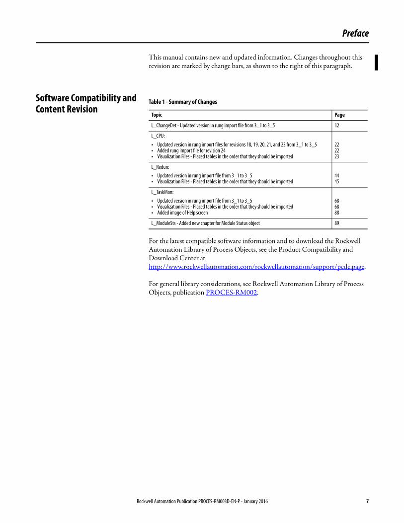
This manual contains new and updated information. Changes throughout this revision are marked by change bars, as shown to the right of this paragraph.
Software Compatibility and Content Revision
For the latest compatible software information and to download the Rockwell Automation Library of Process Objects, see the Product Compatibility and Download Center at http://www.rockwellautomation.com/rockwellautomation/support/pcdc.page.
For general library considerations, see Rockwell Automation Library of Process Objects, publication PROCES-RM002.
Table 1 - Summary of Changes
Topic Page
L_ChangeDet - Updated version in rung import file from 3_1 to 3_5 12
L_CPU:• Updated version in rung import files for revisions 18, 19, 20, 21, and 23 from 3_1 to 3_5• Added rung import file for revision 24• Visualization Files - Placed tables in the order that they should be imported
222223
L_Redun:• Updated version in rung import file from 3_1 to 3_5• Visualization Files - Placed tables in the order that they should be imported
4445
L_TaskMon:• Updated version in rung import file from 3_1 to 3_5• Visualization Files - Placed tables in the order that they should be imported• Added image of Help screen
686888
L_ModuleSts - Added new chapter for Module Status object 89
Rockwell Automation Publication PROCES-RM003D-EN-P - January 2016 7
Preface
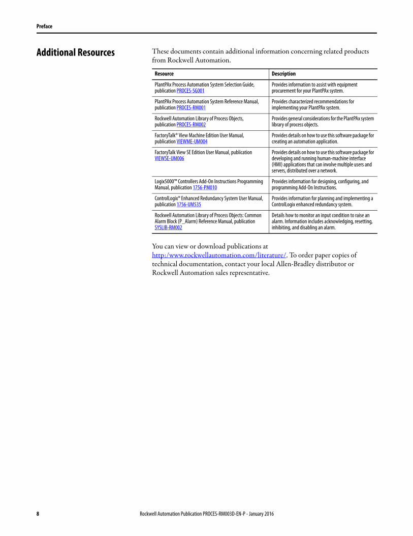
Additional Resources These documents contain additional information concerning related products from Rockwell Automation.
You can view or download publications athttp:/www.rockwellautomation.com/literature/. To order paper copies of technical documentation, contact your local Allen-Bradley distributor or Rockwell Automation sales representative.
Resource Description
PlantPAx Process Automation System Selection Guide, publication PROCES-SG001
Provides information to assist with equipment procurement for your PlantPAx system.
PlantPAx Process Automation System Reference Manual, publication PROCES-RM001
Provides characterized recommendations for implementing your PlantPAx system.
Rockwell Automation Library of Process Objects,publication PROCES-RM002
Provides general considerations for the PlantPAx system library of process objects.
FactoryTalk® View Machine Edition User Manual,publication VIEWME-UM004
Provides details on how to use this software package for creating an automation application.
FactoryTalk View SE Edition User Manual, publication VIEWSE-UM006
Provides details on how to use this software package for developing and running human-machine interface (HMI) applications that can involve multiple users and servers, distributed over a network.
Logix5000™ Controllers Add-On Instructions Programming Manual, publication 1756-PM010
Provides information for designing, configuring, and programming Add-On Instructions.
ControlLogix® Enhanced Redundancy System User Manual, publication 1756-UM535
Provides information for planning and implementing a ControlLogix enhanced redundancy system.
Rockwell Automation Library of Process Objects: Common Alarm Block (P_Alarm) Reference Manual, publication SYSLIB-RM002
Details how to monitor an input condition to raise an alarm. Information includes acknowledging, resetting, inhibiting, and disabling an alarm.
8 Rockwell Automation Publication PROCES-RM003D-EN-P - January 2016

Chapter 1
Logix Change Detector (L_ChangeDet)
The L_ChangeDet (Logix Change Detector) Add-On Instruction monitors another Logix controller on the network and checks for changes that impact operation. Changes that can be monitored include downloads, online edits, I/O forcing, and controller mode changes.
No visualization elements are supplied with the L_ChangeDet instruction.
Rockwell Automation Publication PROCES-RM003D-EN-P - January 2016 9
Chapter 1 Logix Change Detector (L_ChangeDet)
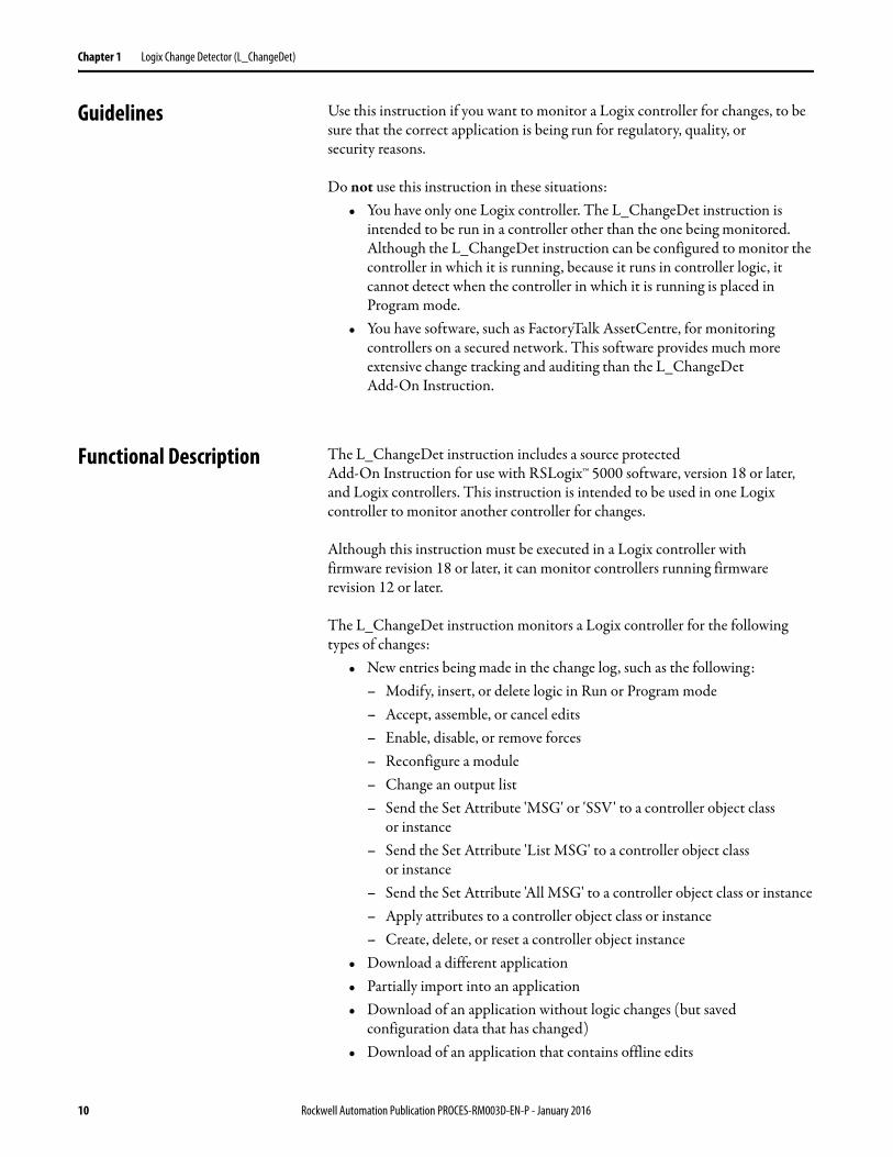
Guidelines Use this instruction if you want to monitor a Logix controller for changes, to be sure that the correct application is being run for regulatory, quality, or security reasons.
Do not use this instruction in these situations:• You have only one Logix controller. The L_ChangeDet instruction is
intended to be run in a controller other than the one being monitored. Although the L_ChangeDet instruction can be configured to monitor the controller in which it is running, because it runs in controller logic, it cannot detect when the controller in which it is running is placed in Program mode.
• You have software, such as FactoryTalk AssetCentre, for monitoring controllers on a secured network. This software provides much more extensive change tracking and auditing than the L_ChangeDet Add-On Instruction.
Functional Description The L_ChangeDet instruction includes a source protectedAdd-On Instruction for use with RSLogix™ 5000 software, version 18 or later, and Logix controllers. This instruction is intended to be used in one Logix controller to monitor another controller for changes.
Although this instruction must be executed in a Logix controller with firmware revision 18 or later, it can monitor controllers running firmware revision 12 or later.
The L_ChangeDet instruction monitors a Logix controller for the following types of changes:
• New entries being made in the change log, such as the following: – Modify, insert, or delete logic in Run or Program mode– Accept, assemble, or cancel edits – Enable, disable, or remove forces – Reconfigure a module – Change an output list – Send the Set Attribute 'MSG' or 'SSV' to a controller object class
or instance– Send the Set Attribute 'List MSG' to a controller object class
or instance– Send the Set Attribute 'All MSG' to a controller object class or instance– Apply attributes to a controller object class or instance– Create, delete, or reset a controller object instance
• Download a different application• Partially import into an application• Download of an application without logic changes (but saved
configuration data that has changed)• Download of an application that contains offline edits
10 Rockwell Automation Publication PROCES-RM003D-EN-P - January 2016
Logix Change Detector (L_ChangeDet) Chapter 1
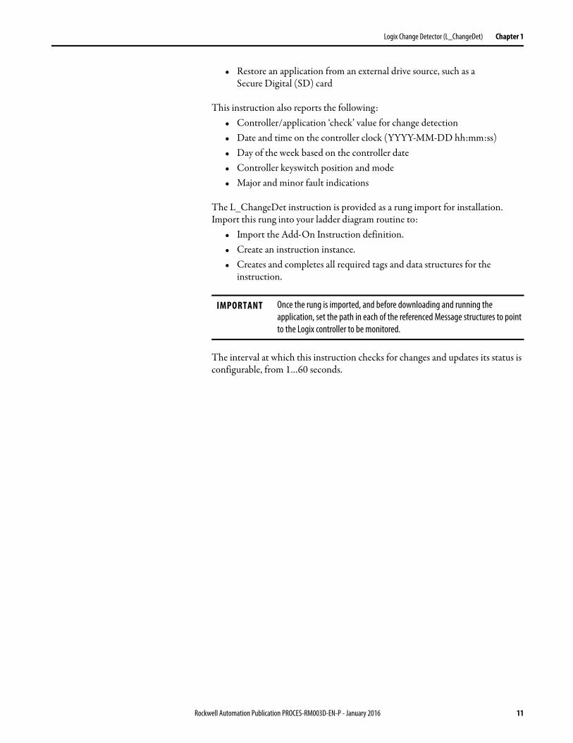
• Restore an application from an external drive source, such as a Secure Digital (SD) card
This instruction also reports the following: • Controller/application ‘check’ value for change detection• Date and time on the controller clock (YYYY-MM-DD hh:mm:ss)• Day of the week based on the controller date• Controller keyswitch position and mode• Major and minor fault indications
The L_ChangeDet instruction is provided as a rung import for installation. Import this rung into your ladder diagram routine to:
• Import the Add-On Instruction definition.• Create an instruction instance.• Creates and completes all required tags and data structures for the
instruction.
The interval at which this instruction checks for changes and updates its status is configurable, from 1…60 seconds.
IMPORTANT Once the rung is imported, and before downloading and running the application, set the path in each of the referenced Message structures to point to the Logix controller to be monitored.
Rockwell Automation Publication PROCES-RM003D-EN-P - January 2016 11
Chapter 1 Logix Change Detector (L_ChangeDet)
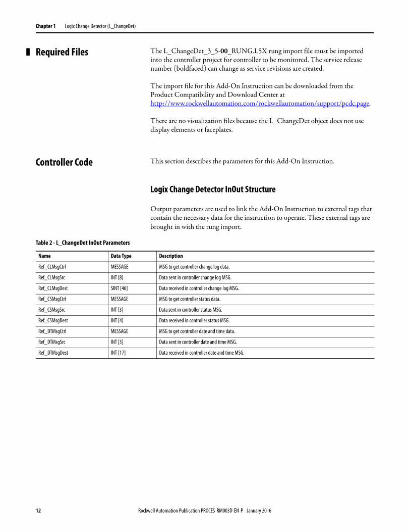
Required Files The L_ChangeDet_3_5-00_RUNG.L5X rung import file must be imported into the controller project for controller to be monitored. The service release number (boldfaced) can change as service revisions are created.
The import file for this Add-On Instruction can be downloaded from the Product Compatibility and Download Center at http://www.rockwellautomation.com/rockwellautomation/support/pcdc.page.
There are no visualization files because the L_ChangeDet object does not use display elements or faceplates.
Controller Code This section describes the parameters for this Add-On Instruction.
Logix Change Detector InOut Structure
Output parameters are used to link the Add-On Instruction to external tags that contain the necessary data for the instruction to operate. These external tags are brought in with the rung import.
Table 2 - L_ChangeDet InOut Parameters
Name Data Type Description
Ref_CLMsgCtrl MESSAGE MSG to get controller change log data.
Ref_CLMsgSrc INT [8] Data sent in controller change log MSG.
Ref_CLMsgDest SINT [46] Data received in controller change log MSG.
Ref_CSMsgCtrl MESSAGE MSG to get controller status data.
Ref_CSMsgSrc INT [3] Data sent in controller status MSG.
Ref_CSMsgDest INT [4] Data received in controller status MSG.
Ref_DTMsgCtrl MESSAGE MSG to get controller date and time data.
Ref_DTMsgSrc INT [3] Data sent in controller date and time MSG.
Ref_DTMsgDest INT [17] Data received in controller date and time MSG.
12 Rockwell Automation Publication PROCES-RM003D-EN-P - January 2016
Logix Change Detector (L_ChangeDet) Chapter 1
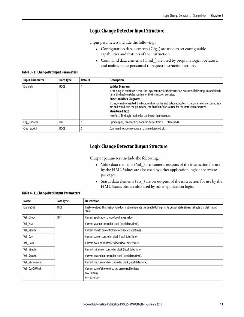
Logix Change Detector Input Structure
Input parameters include the following:• Configuration data elements (Cfg_) are used to set configurable
capabilities and features of the instruction.• Command data elements (Cmd_) are used by program logic, operators,
and maintenance personnel to request instruction actions.
Logix Change Detector Output Structure
Output parameters include the following:• Value data elements (Val_) are numeric outputs of the instruction for use
by the HMI. Values are also used by other application logic or software packages.
• Status data elements (Sts_) are bit outputs of the instruction for use by the HMI. Status bits are also used by other application logic.
Table 3 - L_ChangeDet Input Parameters
Input Parameter Data Type Default Description
EnableIn BOOL 1 Ladder Diagram:If the rung-in condition is true, the Logic routine for the instruction executes. If the rung-in condition is false, the EnableInFalse routine for the instruction executes.Function Block Diagram:If true, or not connected, the Logic routine for the instruction executes. If the parameter is exposed as a pin and wired, and the pin is false, the EnableInFalse routine for the instruction executes.Structured Text:No effect. The Logic routine for the instruction executes.
Cfg_UpdateT DINT 5 Update (poll) time for CPU data can be set from 1…60 seconds.
Cmd_AckAll BOOL 0 Command to acknowledge all change detected bits.
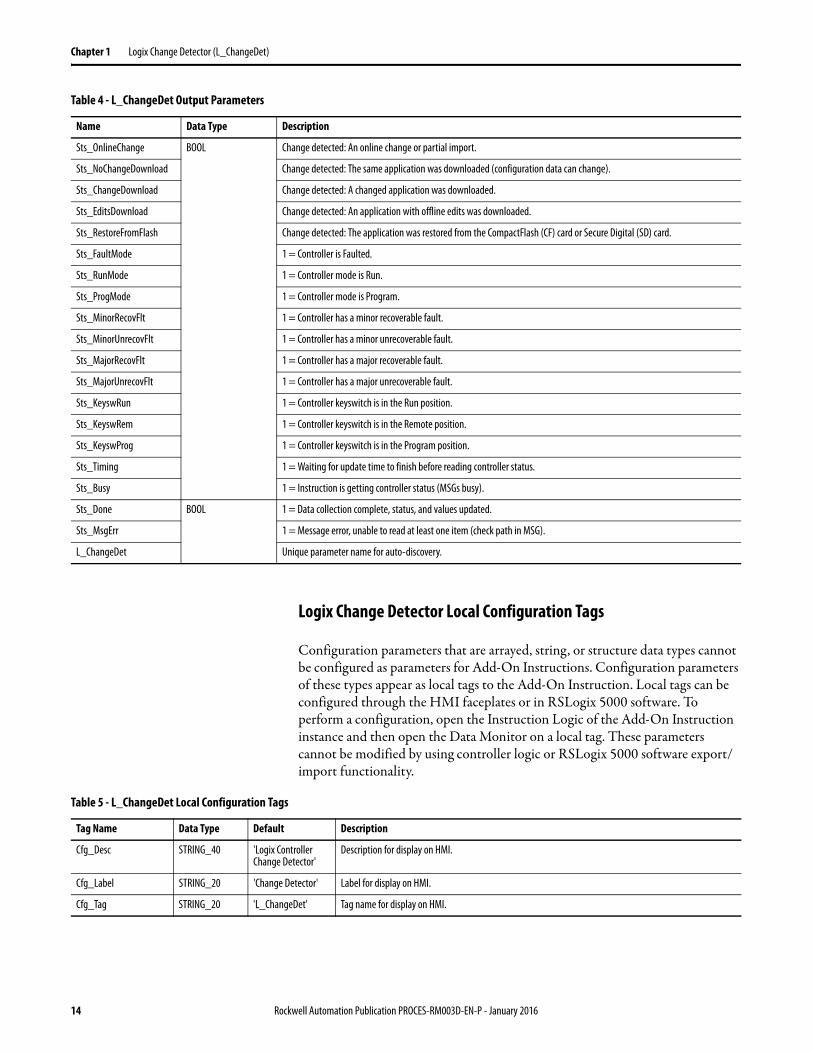
Table 4 - L_ChangeDet Output Parameters
Name Data Type Description
EnableOut BOOL Enable output: This instruction does not manipulate the EnableOut signal. Its output state always reflects EnableIn Input state.
Val_Check DINT Current application check-for-change value.
Val_Year Current year on controller clock (local date/time).
Val_Month Current month on controller clock (local date/time).
Val_Day Current day on controller clock (local date/time).
Val_Hour Current hour on controller clock (local date/time).
Val_Minute Current minute on controller clock (local date/time).
Val_Second Current second on controller clock (local date/time).
Val_Microsecond Current microsecond on controller clock (local date/time).
Val_DayOfWeek Current day of the week based on controller date:0 = Sunday6 = Saturday
Rockwell Automation Publication PROCES-RM003D-EN-P - January 2016 13
Chapter 1 Logix Change Detector (L_ChangeDet)
Logix Change Detector Local Configuration Tags
Configuration parameters that are arrayed, string, or structure data types cannot be configured as parameters for Add-On Instructions. Configuration parameters of these types appear as local tags to the Add-On Instruction. Local tags can be configured through the HMI faceplates or in RSLogix 5000 software. To perform a configuration, open the Instruction Logic of the Add-On Instruction instance and then open the Data Monitor on a local tag. These parameters cannot be modified by using controller logic or RSLogix 5000 software export/import functionality.
Sts_OnlineChange BOOL Change detected: An online change or partial import.
Sts_NoChangeDownload Change detected: The same application was downloaded (configuration data can change).
Sts_ChangeDownload Change detected: A changed application was downloaded.
Sts_EditsDownload Change detected: An application with offline edits was downloaded.
Sts_RestoreFromFlash Change detected: The application was restored from the CompactFlash (CF) card or Secure Digital (SD) card.
Sts_FaultMode 1 = Controller is Faulted.
Sts_RunMode 1 = Controller mode is Run.
Sts_ProgMode 1 = Controller mode is Program.
Sts_MinorRecovFlt 1 = Controller has a minor recoverable fault.
Sts_MinorUnrecovFlt 1 = Controller has a minor unrecoverable fault.
Sts_MajorRecovFlt 1 = Controller has a major recoverable fault.
Sts_MajorUnrecovFlt 1 = Controller has a major unrecoverable fault.
Sts_KeyswRun 1 = Controller keyswitch is in the Run position.
Sts_KeyswRem 1 = Controller keyswitch is in the Remote position.
Sts_KeyswProg 1 = Controller keyswitch is in the Program position.
Sts_Timing 1 = Waiting for update time to finish before reading controller status.
Sts_Busy 1 = Instruction is getting controller status (MSGs busy).
Sts_Done BOOL 1 = Data collection complete, status, and values updated.
Sts_MsgErr 1 = Message error, unable to read at least one item (check path in MSG).
L_ChangeDet Unique parameter name for auto-discovery.
Table 4 - L_ChangeDet Output Parameters
Name Data Type Description
Table 5 - L_ChangeDet Local Configuration Tags
Tag Name Data Type Default Description
Cfg_Desc STRING_40 'Logix Controller Change Detector'
Description for display on HMI.
Cfg_Label STRING_20 'Change Detector' Label for display on HMI.
Cfg_Tag STRING_20 'L_ChangeDet' Tag name for display on HMI.
14 Rockwell Automation Publication PROCES-RM003D-EN-P - January 2016
Logix Change Detector (L_ChangeDet) Chapter 1
Operations Modes
The L_ChangeDet instruction has no commands or outputs intended to control equipment and therefore does not have any modes.
Alarms
The L_ChangeDet Add-On Instruction does not provide any alarms. If an alarm is required, connect the output status to be alarmed to a P_Alarm instruction.
Simulation
The L_ChangeDet Add-On Instruction does not have a Simulation capability.
Execution
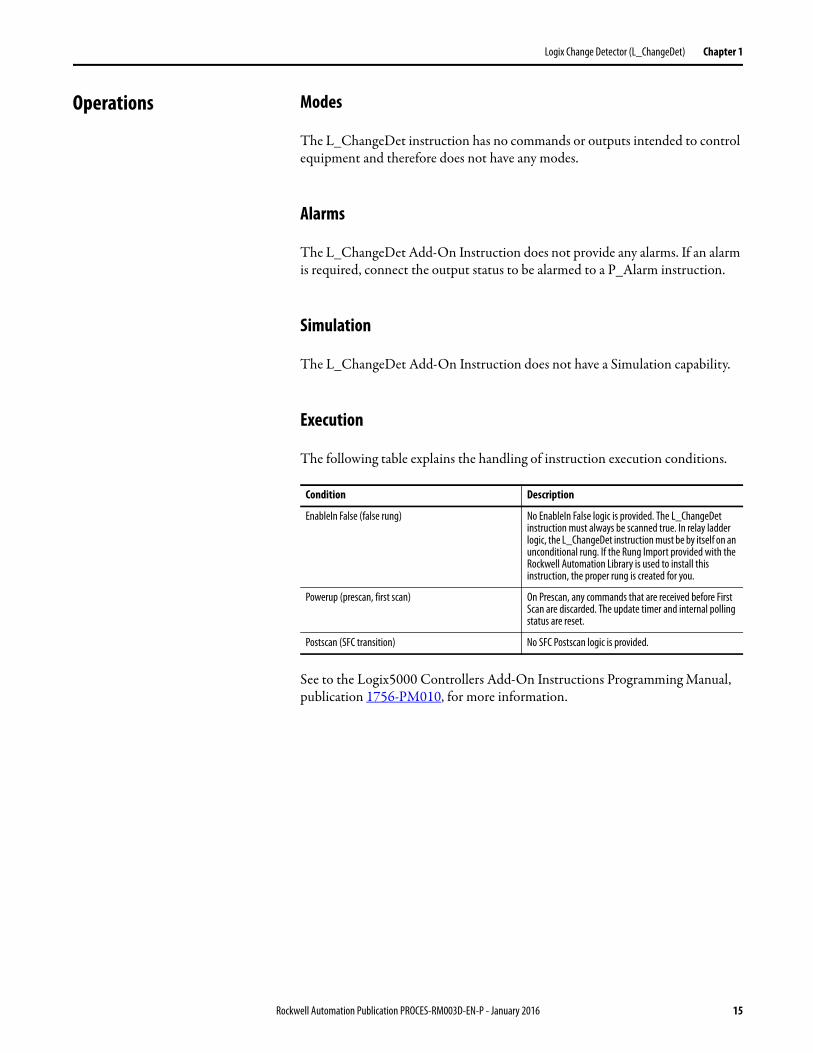
The following table explains the handling of instruction execution conditions.
See to the Logix5000 Controllers Add-On Instructions Programming Manual, publication 1756-PM010, for more information.
Condition Description
EnableIn False (false rung) No EnableIn False logic is provided. The L_ChangeDet instruction must always be scanned true. In relay ladder logic, the L_ChangeDet instruction must be by itself on an unconditional rung. If the Rung Import provided with the Rockwell Automation Library is used to install this instruction, the proper rung is created for you.
Powerup (prescan, first scan) On Prescan, any commands that are received before First Scan are discarded. The update timer and internal polling status are reset.
Postscan (SFC transition) No SFC Postscan logic is provided.
Rockwell Automation Publication PROCES-RM003D-EN-P - January 2016 15
Chapter 1 Logix Change Detector (L_ChangeDet)
Programming Example The L_ChangeDet instruction is provided fully configured as a rung import; so little programming is required for the instruction to be used. This programming example shows how the rung import is used to instantiate the L_ChangeDet instruction.
Since the L_ChangeDet instruction is a rung import, it must be created in a Ladder Diagram routine. By default, L_ChangeDet checks controllers for changes only every 5 seconds, so the ladder routine does not need to run in a fast periodic task.
The following steps describe how you instantiate L_ChangeDet in your routine.
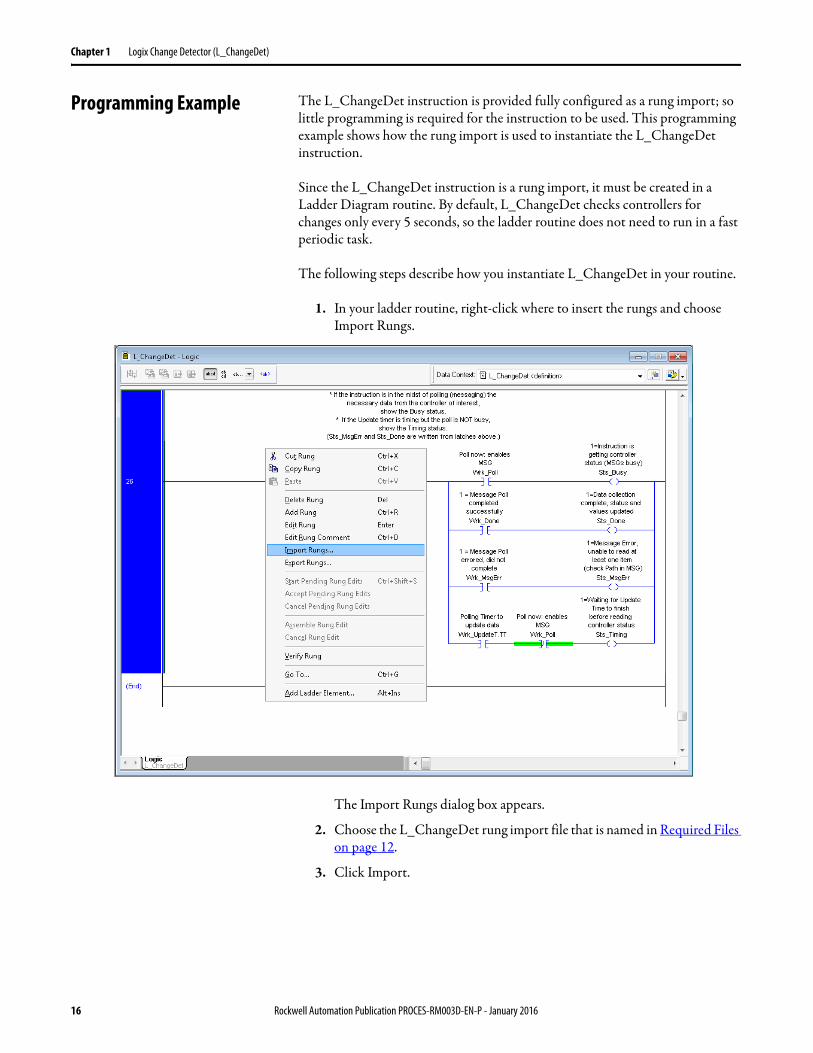
1. In your ladder routine, right-click where to insert the rungs and choose Import Rungs.
The Import Rungs dialog box appears.
2. Choose the L_ChangeDet rung import file that is named in Required Files on page 12.
3. Click Import.
16 Rockwell Automation Publication PROCES-RM003D-EN-P - January 2016
Logix Change Detector (L_ChangeDet) Chapter 1
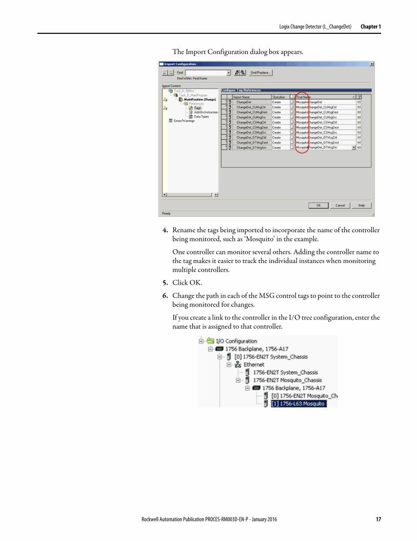
The Import Configuration dialog box appears.
4. Rename the tags being imported to incorporate the name of the controller being monitored, such as ‘Mosquito’ in the example.
One controller can monitor several others. Adding the controller name to the tag makes it easier to track the individual instances when monitoring multiple controllers.
5. Click OK.
6. Change the path in each of the MSG control tags to point to the controller being monitored for changes.
If you create a link to the controller in the I/O tree configuration, enter the name that is assigned to that controller.
Rockwell Automation Publication PROCES-RM003D-EN-P - January 2016 17
Chapter 1 Logix Change Detector (L_ChangeDet)
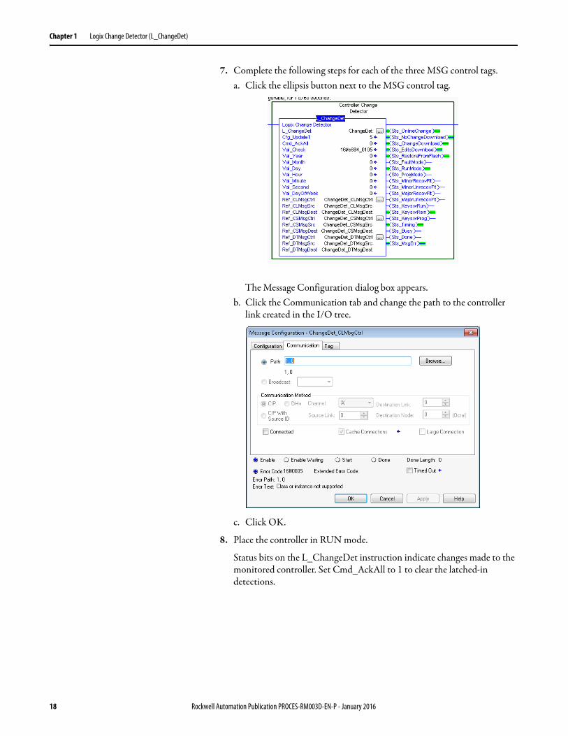
7. Complete the following steps for each of the three MSG control tags.a. Click the ellipsis button next to the MSG control tag.
The Message Configuration dialog box appears.b. Click the Communication tab and change the path to the controller
link created in the I/O tree.
c. Click OK.
8. Place the controller in RUN mode.
Status bits on the L_ChangeDet instruction indicate changes made to the monitored controller. Set Cmd_AckAll to 1 to clear the latched-in detections.
18 Rockwell Automation Publication PROCES-RM003D-EN-P - January 2016
Chapter 2
Logix Controller CPU Utilization (L_CPU)
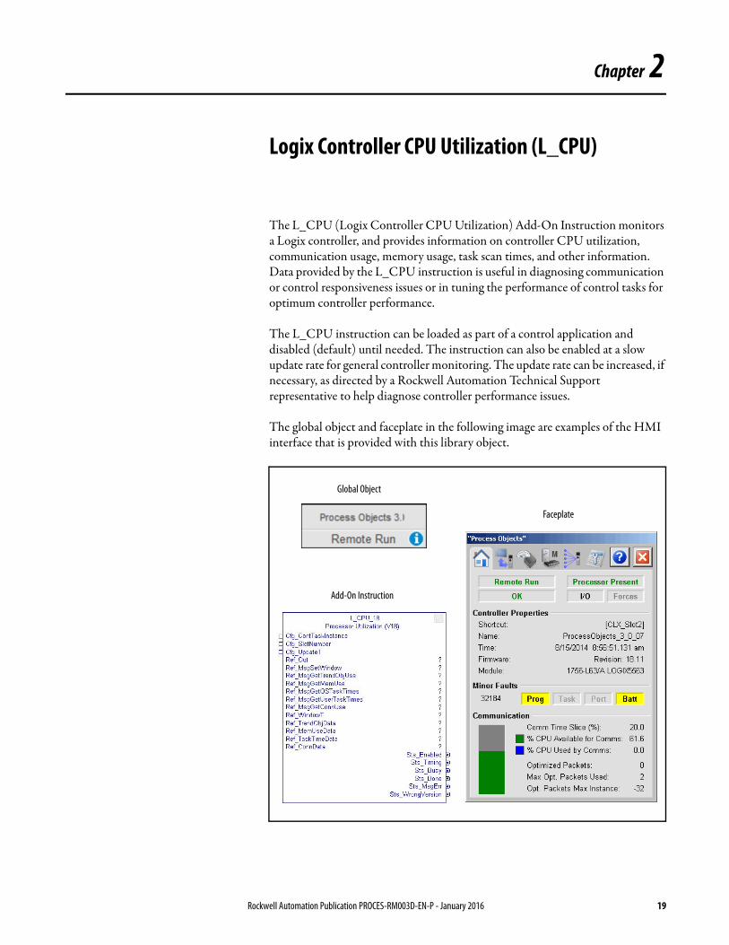
The L_CPU (Logix Controller CPU Utilization) Add-On Instruction monitors a Logix controller, and provides information on controller CPU utilization, communication usage, memory usage, task scan times, and other information. Data provided by the L_CPU instruction is useful in diagnosing communication or control responsiveness issues or in tuning the performance of control tasks for optimum controller performance.
The L_CPU instruction can be loaded as part of a control application and disabled (default) until needed. The instruction can also be enabled at a slow update rate for general controller monitoring. The update rate can be increased, if necessary, as directed by a Rockwell Automation Technical Support representative to help diagnose controller performance issues.
The global object and faceplate in the following image are examples of the HMI interface that is provided with this library object.
Global Object
Add-On Instruction
Faceplate
Rockwell Automation Publication PROCES-RM003D-EN-P - January 2016 19
Chapter 2 Logix Controller CPU Utilization (L_CPU)
Guidelines Use this instruction in these situations:• Monitor general controller resource utilization:
– Processor utilization– Memory usage– Communication capacity– Networking performance and connection usage
• Gather data to help resolve a specific issue under the direction of a Rockwell Automation Technical Support representative
• Tune the periods or priorities of multiple tasks in a controller to optimize control and observe how changes in task configuration affect CPU and other resource usage in the controller
Do not use this instruction at a high update rate on a continuing basis. The L_CPU instruction increases the communication load on the controller when it is polling for performance data. At high update rates, the resource load generated by the L_CPU instruction polling can affect control performance, especially if you already have a fully loaded controller.
20 Rockwell Automation Publication PROCES-RM003D-EN-P - January 2016
Logix Controller CPU Utilization (L_CPU) Chapter 2
Functional Description The L_CPU instruction collects and summarizes various data from the Logix controller that is being monitored. This information includes the following:
• Processor Identity information:– Catalog number and description– Major and minor firmware revision numbers
• Communication Responsiveness information:– CPU% available for responding to communication requests– CPU% used for responding to communication requests– Optimized Packets that are used for responding to communication
requests• Memory usage (total and for each of several classes of memory):
– Total memory size– Memory used– Memory available– Largest contiguous block of available memory
• CPU utilization (%):– Continuous task (or unused CPU, if no continuous task)– Periodic and Event tasks– Motion/synchronization– Safety tasks– Redundancy– Sending messages (MSG)– Responding to communication requests (such as from HMI)– System (I/O scan, timer updates, everything else)
• Communication connection usage:– Total connections available– Connections that are used for each of several classes of communication– Unconnected buffers and cached messages
• I/O Forcing status• Controller minor faults• Communication timeslice setting
IMPORTANT The L_CPU instruction does not support SoftLogix™ 5800 or RSLogix™ Emulate 5000 controllers.
Rockwell Automation Publication PROCES-RM003D-EN-P - January 2016 21
Chapter 2 Logix Controller CPU Utilization (L_CPU)
The items listed previously are displayed on several faceplate tabs, with summary information on the main (home) tab.
Required Files Add-On Instructions are reusable code objects that contain encapsulated logic that can streamline implementing your system. This code lets you create your own instruction set for programming logic as a supplement to the instruction set provided natively in the ControlLogix® firmware. An Add-On Instruction is defined once in each controller project, and can be instantiated multiple times in your application code as needed.
Controller Files
The following rung imports must be imported into the controller for each instance of L_CPU in your project:
• L_CPU_18_3_5-00_RUNG.L5X• L_CPU_19_3_5-00_RUNG.L5X• L_CPU_20_3_5-00_RUNG.L5X • L_CPU_21_3_5-00_RUNG.L5X• L_CPU_23_3_5-00_RUNG.1.5X• L_CPU_24_3_5-00_RUNG.1.5X
You select the appropriate file based on the revision of the controller being used (18, 19, 20, 21, 23, or 24). The service release number (boldfaced) can change as service revisions are created.
The import file can be downloaded from the Product Compatibility and Download Center at http://www.rockwellautomation.com/rockwellautomation/support/pcdc.page.
TIP We recommend that you access the L_CPU faceplate when you contact Rockwell Automation Technical Support. The information on the Operator (home) tab is often requested when you call. You'll will also need your RSLogix 5000 software serial number or other license or support contract information. The Maintenance tab has a space for you to record this information for reference.
22 Rockwell Automation Publication PROCES-RM003D-EN-P - January 2016
Logix Controller CPU Utilization (L_CPU) Chapter 2
Visualization Files
The Process Library contains visualization files for built-in firmware instructions which provide a common user interface. These files can be downloaded from the Product Compatibility and Download Center at http://www.rockwellautomation.com/global/support/pcdc.page.
This Add-On Instruction has associated visualization files that provide a common user interface. These files can be downloaded from the Product Compatibility and Download Center at http://www.rockwellautomation.com/rockwellautomation/support/pcdc.page.
Images are external graphic files that can be used in displays. They must be imported for FactoryTalk View to make use of them.
When PNG files are imported, they are renamed by FactoryTalk View with a .bmp file extension, but retain a .png format.
The Global Object files (.ggfx file type) in the following table are Process Library display elements that are created once and referenced multiple times on multiple displays in an application. When changes are made to a Global Object, all instances in the application are automatically updated.
The Standard Display files (.gfx file type) in the following table are the Process Library displays that you see at runtime.
IMPORTANT The visualization file dependencies require Process Library content imports to occur in a specific order as reflected in the following tables:• Images• Global Objects• Standard Displays• HMI Tags• Macros
Table 6 - Visualization Files: Images (.png)
FactoryTalk View SE Software FactoryTalk View ME Software Description
All .png files in the images folder All .png files in the images folder These are the common icons used in the global objects and standard displays for all Process Objects.
Table 7 - Visualization Files: Global Objects (.ggfx)
FactoryTalk View SE Software FactoryTalk View ME Software Description
(RA-BAS) BuiltIn Faceplate Objects (RA-BAS-ME) BuiltIn Faceplate Objects Global objects for built-in instruction faceplates.
(RA-BAS) BuiltIn Graphics Librarys (RA-BAS-ME) BuiltIn Graphics Librarys Global object device symbols used to build built-in instruction graphics.
(RA-BAS) BuiltIn Help Objects (RA-BAS-ME) BuiltIn Help Objects Global objects for built-in instruction Help displays.
(RA-BAS) Common Faceplate Objects (RA-BAS-ME) Common Faceplate Objects Global objects used on process object faceplates.
(RA-BAS) Logix Faceplate Objects (RA-BAS-ME) Logix Faceplate Objects Global objects used on Logix faceplates.
(RA-BAS) Logix Graphics Library (RA-BAS-ME) Logix Graphics Library Global object device symbols used to build displays for all Logix Objects.
Rockwell Automation Publication PROCES-RM003D-EN-P - January 2016 23
Chapter 2 Logix Controller CPU Utilization (L_CPU)
HMI Tags are created in a FactoryTalk View ME application to support tab switching on Process Library faceplates. The HMI tags may be imported via the comma-separated values file (.csv file type) in the following table.
Controller Code This section describes the parameter references for this Add-On Instruction.
Logix Controller CPU Utilization InOut Structure
Input/output parameters are used to link the Add-On Instruction to external tags that contain necessary data for the instruction to operate. These external tags are brought in with the rung import.
Table 8 - Visualization Files: Standard Displays (.gfx)
FactoryTalk View SE Software FactoryTalk View ME Software Description
(RA-BAS) Built-In Family-Help (RA-BAS-ME) Built-In Family-Help Built-in instruction help information that is accessed from the built-in faceplates.
(RA-BAS) Common-AnalogEdit N/A Faceplate used for analog input data entry. The FactoryTalk View ME faceplates use the native analog input data entry so no file is required.
(RA-BAS) L_CPU-Faceplate (RA-BAS-ME) L_CPU-Faceplate The faceplate that is used for the object.
(RA-BAS) L_Logix Family-Help (RA-BAS-ME) L_Logix Family-Help The Help display that is used for the object.
(RA-BAS) Built-In Totalizer-Faceplate (RA-BAS-ME) Built-In Totalizer Faceplate OptionalThe faceplate display used for the Totalizer object.
(RA-BAS) Built-In TotalizerTgt-Faceplate (RA-BAS-ME) Built-In TotalizerTgt Faceplate OptionalThe faceplate display used for the Totalizer Target object.
Table 9 - Visualization Files: HMI Tags (.csv)
FactoryTalk View SE Software FactoryTalk View ME Software Description
N/A FTVME_PlantPAxLib_Tags_3_5_xx.csvwhere xx = the service release number.
These tags must be imported into theFactoryTalk View ME project to support switching tabs on any Process Object faceplate.
Table 12 - L_CPU InOut Parameters
Name Data Type Description
Ref_Out L_CPU_Out Tag to receive CPU data.
Ref_MsgSetWindow MESSAGE Message to set data collection window time.
Ref_MsgGetTrendObjUse Message to get trend object usage.
Ref_MsgGetMemUse Message to get memory usage.
Ref_MsgGetOSTaskTimes Message to get Logix O/S task times/CPU utilization.
Ref_MsgGetUserTaskTimes Message to get user task time/CPU utilization.
Ref_MsgGetConnUse Message to get connection usage.
Ref_WindowT DINT Window time, in microseconds, to task metrics object.
24 Rockwell Automation Publication PROCES-RM003D-EN-P - January 2016
Logix Controller CPU Utilization (L_CPU) Chapter 2
Logix Controller CPU Utilization Input Structure
Input parameters include the following:• Configuration data elements (Cfg_) are used to set configurable
capabilities and features of the instruction.• Command data elements (Cmd_) are used by program logic, operators,
and maintenance personnel to request instruction action.
Ref_TrendObjData INT [16] Raw trend object data from MSG (trending object).
Ref_MemUseData INT [48] Raw memory use data from MSG (UserMemory object).
Ref_TaskTimeData DINT [131] Raw task time data from MSG (TaskMetrics object).
Ref_ConnData INT [80] Raw connection data from MSG (PortCapacity object).
Table 12 - L_CPU InOut Parameters
Table 13 - L_CPU Input Parameters
Input Parameter Data Type Default Description
EnableIn BOOL 1 Ladder Diagram:If the rung-in condition is true, the Logic routine for the instruction executes. If the rung-in condition is false, the EnableInFalse routine for the instruction executes.Function Block Diagram:If true, or not connected, the Logic routine fore the instruction executes. If the parameter is exposed as a pin and wired, and the pin is false, the EnableInFalse routine for the instruction executes.Structured Text:No effect. The Logic routine for the instruction executes.
Cfg_ContTaskInstance DINT 0 Instance number of Continuous task if it exists (0…31). Set to 0 if there is no Continuous task in this controller.
Cfg_SlotNumber 0 Controller slot number in local chassis.IMPORTANT: Changes to this configuration value take effect after a controller power cycle or PROG-to-RUN controller mode transition.
Cfg_UpdateT 5 Update (poll) time for CPU data (seconds).
Cfg_WindowT REAL 1.0 Window time for collecting task data (seconds).For best results, this value can be set to a common multiple of the configured Periodic Task rates. For the Task configuration provided in the PlantPAx template applications, the default value of 1.0 seconds is appropriate. Values from 1.0…2.0 seconds can be used if possible. For example, your controller has Periodic Tasks that are configured for rates of 100 milliseconds, 400 milliseconds and 800 milliseconds. Set Cfg_WindowT to 1.6 seconds (1600 ms). IMPORTANT: Changes to this configuration value take effect after a controller power cycle or PROG-to-RUN controller mode transition.
MCmd_Enable BOOL 0 Maintenance command to enable or disable collection of data.
MCmd_Disable
Rockwell Automation Publication PROCES-RM003D-EN-P - January 2016 25
Chapter 2 Logix Controller CPU Utilization (L_CPU)
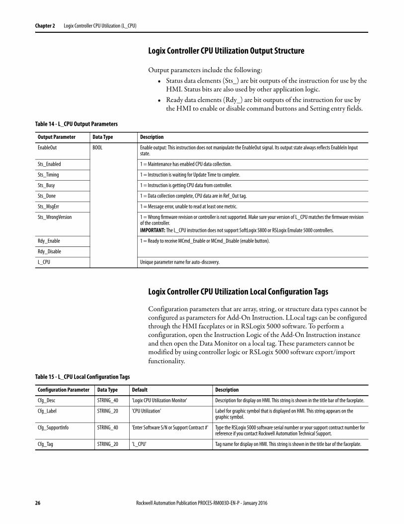
Logix Controller CPU Utilization Output Structure
Output parameters include the following:• Status data elements (Sts_) are bit outputs of the instruction for use by the
HMI. Status bits are also used by other application logic.• Ready data elements (Rdy_) are bit outputs of the instruction for use by
the HMI to enable or disable command buttons and Setting entry fields.
Logix Controller CPU Utilization Local Configuration Tags
Configuration parameters that are array, string, or structure data types cannot be configured as parameters for Add-On Instruction. LLocal tags can be configured through the HMI faceplates or in RSLogix 5000 software. To perform a configuration, open the Instruction Logic of the Add-On Instruction instance and then open the Data Monitor on a local tag. These parameters cannot be modified by using controller logic or RSLogix 5000 software export/import functionality.
Table 14 - L_CPU Output Parameters
Output Parameter Data Type Description
EnableOut BOOL Enable output: This instruction does not manipulate the EnableOut signal. Its output state always reflects EnableIn Input state.
Sts_Enabled 1 = Maintenance has enabled CPU data collection.
Sts_Timing 1 = Instruction is waiting for Update Time to complete.
Sts_Busy 1 = Instruction is getting CPU data from controller.
Sts_Done 1 = Data collection complete, CPU data are in Ref_Out tag.
Sts_MsgErr 1 = Message error, unable to read at least one metric.
Sts_WrongVersion 1 = Wrong firmware revision or controller is not supported. Make sure your version of L_CPU matches the firmware revision of the controller.IMPORTANT: The L_CPU instruction does not support SoftLogix 5800 or RSLogix Emulate 5000 controllers.
Rdy_Enable 1 = Ready to receive MCmd_Enable or MCmd_Disable (enable button).
Rdy_Disable
L_CPU Unique parameter name for auto-discovery.
Table 15 - L_CPU Local Configuration Tags
Configuration Parameter Data Type Default Description
Cfg_Desc STRING_40 'Logix CPU Utilization Monitor' Description for display on HMI. This string is shown in the title bar of the faceplate.
Cfg_Label STRING_20 'CPU Utilization' Label for graphic symbol that is displayed on HMI. This string appears on the graphic symbol.
Cfg_SupportInfo STRING_40 'Enter Software S/N or Support Contract #' Type the RSLogix 5000 software serial number or your support contract number for reference if you contact Rockwell Automation Technical Support.
Cfg_Tag STRING_20 'L_CPU' Tag name for display on HMI. This string is shown in the title bar of the faceplate.
26 Rockwell Automation Publication PROCES-RM003D-EN-P - January 2016
Logix Controller CPU Utilization (L_CPU) Chapter 2
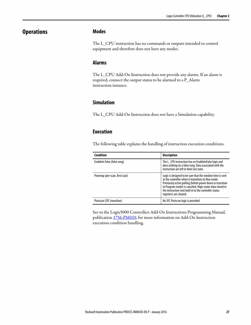
Operations Modes
The L_CPU instruction has no commands or outputs intended to control equipment and therefore does not have any modes.
Alarms
The L_CPU Add-On Instruction does not provide any alarms. If an alarm is required, connect the output status to be alarmed to a P_Alarm instruction instance.
Simulation
The L_CPU Add-On Instruction does not have a Simulation capability.
Execution
The following table explains the handling of instruction execution conditions.
See to the Logix5000 Controllers Add-On Instructions Programming Manual, publication 1756-PM010, for more information on Add-On Instruction execution condition handling.
Condition Description
EnableIn False (false rung) The L_CPU instruction has no EnableInFalse logic and does nothing on a false rung. Data associated with the instruction are left in their last state.
Powerup (pre-scan, first scan) Logic is designed to be sure that the window time is sent to the controller when it transitions to Run mode. Previously active polling (before power down or transition to Program mode) is canceled. High-water data stored in the instruction (not built in to the controller status registers) are cleared.
Postscan (SFC transition) No SFC Postscan logic is provided.
Rockwell Automation Publication PROCES-RM003D-EN-P - January 2016 27
Chapter 2 Logix Controller CPU Utilization (L_CPU)
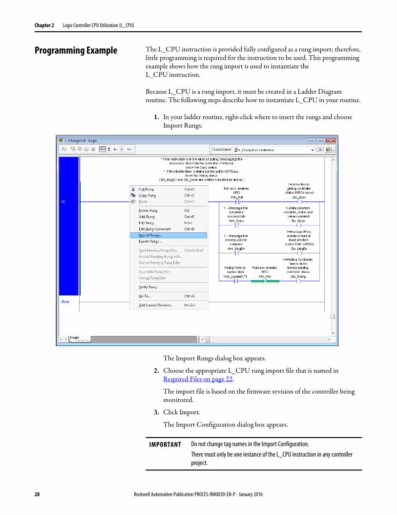
Programming Example The L_CPU instruction is provided fully configured as a rung import; therefore, little programming is required for the instruction to be used. This programming example shows how the rung import is used to instantiate the L_CPU instruction.
Because L_CPU is a rung import, it must be created in a Ladder Diagram routine. The following steps describe how to instantiate L_CPU in your routine.
1. In your ladder routine, right-click where to insert the rungs and choose Import Rungs.
The Import Rungs dialog box appears.
2. Choose the appropriate L_CPU rung import file that is named in Required Files on page 22.
The import file is based on the firmware revision of the controller being monitored.
3. Click Import.
The Import Configuration dialog box appears.
IMPORTANT Do not change tag names in the Import Configuration.There must only be one instance of the L_CPU instruction in any controller project.
28 Rockwell Automation Publication PROCES-RM003D-EN-P - January 2016
Logix Controller CPU Utilization (L_CPU) Chapter 2
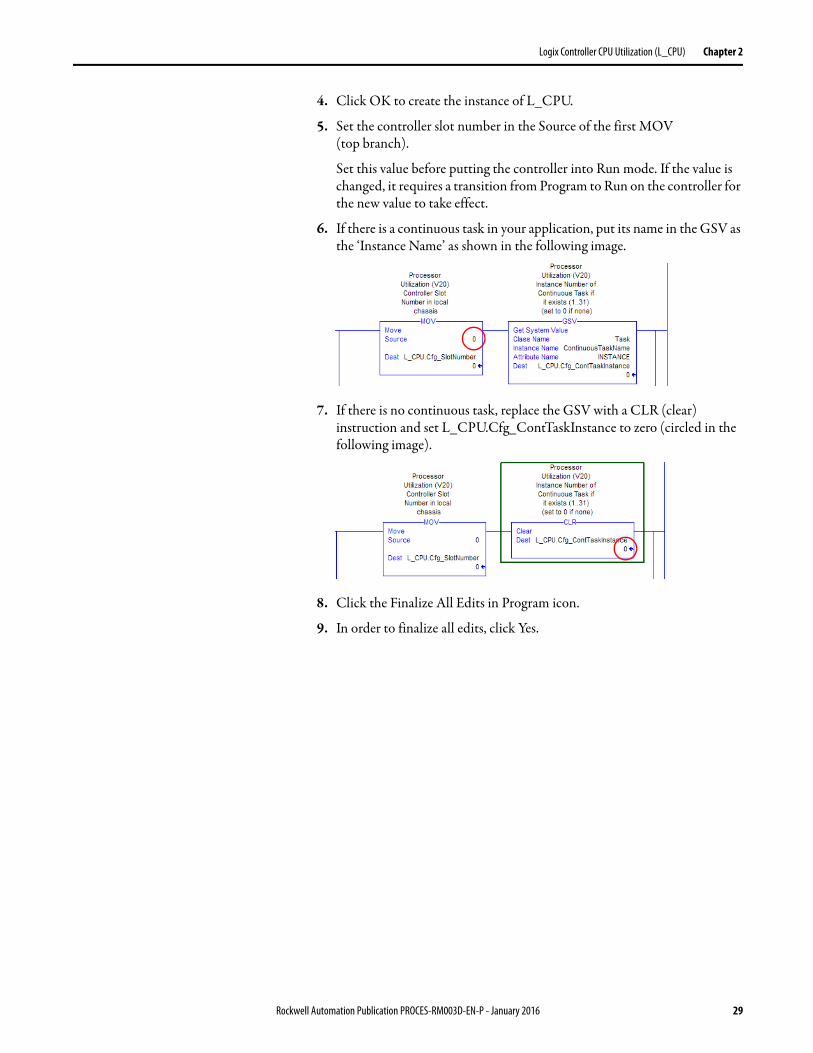
4. Click OK to create the instance of L_CPU.
5. Set the controller slot number in the Source of the first MOV(top branch).
Set this value before putting the controller into Run mode. If the value is changed, it requires a transition from Program to Run on the controller for the new value to take effect.
6. If there is a continuous task in your application, put its name in the GSV as the ‘Instance Name’ as shown in the following image.
7. If there is no continuous task, replace the GSV with a CLR (clear) instruction and set L_CPU.Cfg_ContTaskInstance to zero (circled in the following image).
8. Click the Finalize All Edits in Program icon.
9. In order to finalize all edits, click Yes.
Rockwell Automation Publication PROCES-RM003D-EN-P - January 2016 29
Chapter 2 Logix Controller CPU Utilization (L_CPU)
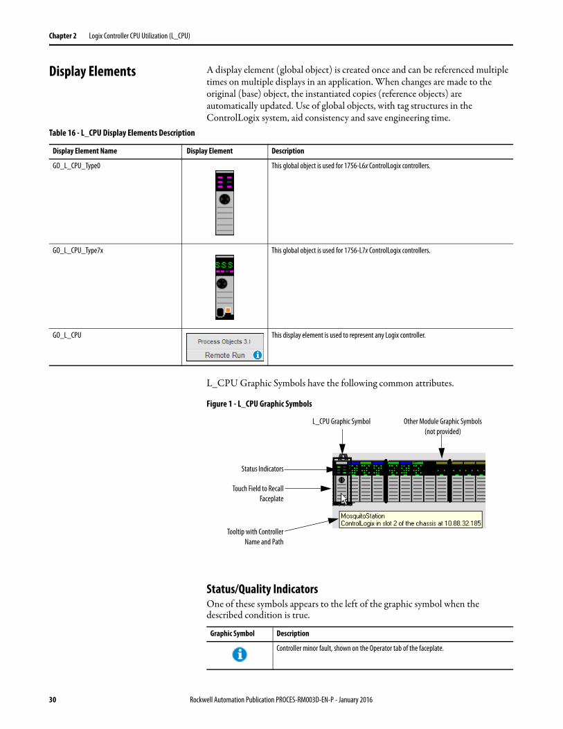
Display Elements A display element (global object) is created once and can be referenced multiple times on multiple displays in an application. When changes are made to the original (base) object, the instantiated copies (reference objects) are automatically updated. Use of global objects, with tag structures in the ControlLogix system, aid consistency and save engineering time.
L_CPU Graphic Symbols have the following common attributes.
Figure 1 - L_CPU Graphic Symbols
Status/Quality IndicatorsOne of these symbols appears to the left of the graphic symbol when the described condition is true.
Table 16 - L_CPU Display Elements Description
Display Element Name Display Element Description
GO_L_CPU_Type0 This global object is used for 1756-L6x ControlLogix controllers.
GO_L_CPU_Type7x This global object is used for 1756-L7x ControlLogix controllers.
GO_L_CPU This display element is used to represent any Logix controller.
Graphic Symbol Description
Controller minor fault, shown on the Operator tab of the faceplate.
Status Indicators
L_CPU Graphic Symbol
Touch Field to RecallFaceplate
Tooltip with ControllerName and Path
Other Module Graphic Symbols(not provided)
30 Rockwell Automation Publication PROCES-RM003D-EN-P - January 2016
Logix Controller CPU Utilization (L_CPU) Chapter 2
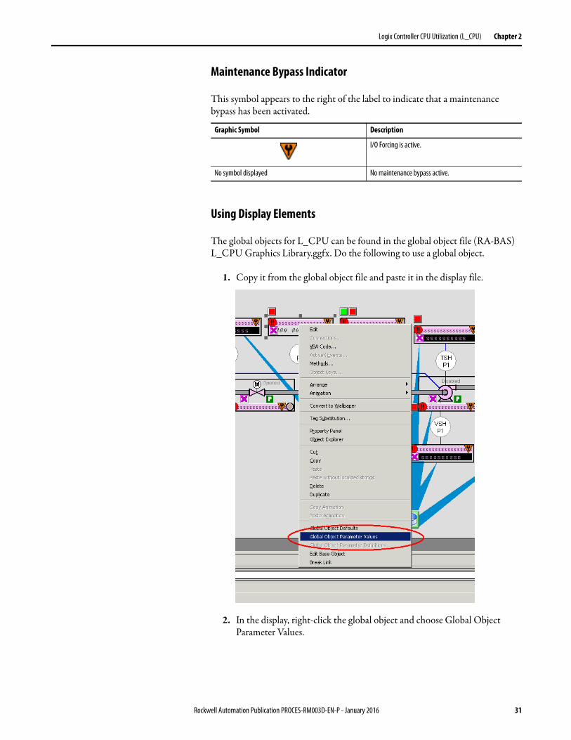
Maintenance Bypass Indicator
This symbol appears to the right of the label to indicate that a maintenance bypass has been activated.
Using Display Elements
The global objects for L_CPU can be found in the global object file (RA-BAS) L_CPU Graphics Library.ggfx. Do the following to use a global object.
1. Copy it from the global object file and paste it in the display file.
2. In the display, right-click the global object and choose Global Object Parameter Values.
Graphic Symbol Description
I/O Forcing is active.
No symbol displayed No maintenance bypass active.
Rockwell Automation Publication PROCES-RM003D-EN-P - January 2016 31
Chapter 2 Logix Controller CPU Utilization (L_CPU)
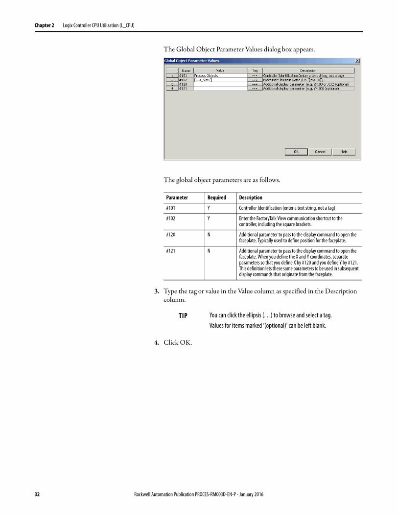
The Global Object Parameter Values dialog box appears.
The global object parameters are as follows.
3. Type the tag or value in the Value column as specified in the Description column.
4. Click OK.
Parameter Required Description
#101 Y Controller Identification (enter a text string, not a tag)
#102 Y Enter the FactoryTalk View communication shortcut to the controller, including the square brackets.
#120 N Additional parameter to pass to the display command to open the faceplate. Typically used to define position for the faceplate.
#121 N Additional parameter to pass to the display command to open the faceplate. When you define the X and Y coordinates, separate parameters so that you define X by #120 and you define Y by #121. This definition lets these same parameters to be used in subsequent display commands that originate from the faceplate.
TIP You can click the ellipsis (. . .) to browse and select a tag. Values for items marked ‘(optional)’ can be left blank.
32 Rockwell Automation Publication PROCES-RM003D-EN-P - January 2016
Logix Controller CPU Utilization (L_CPU) Chapter 2
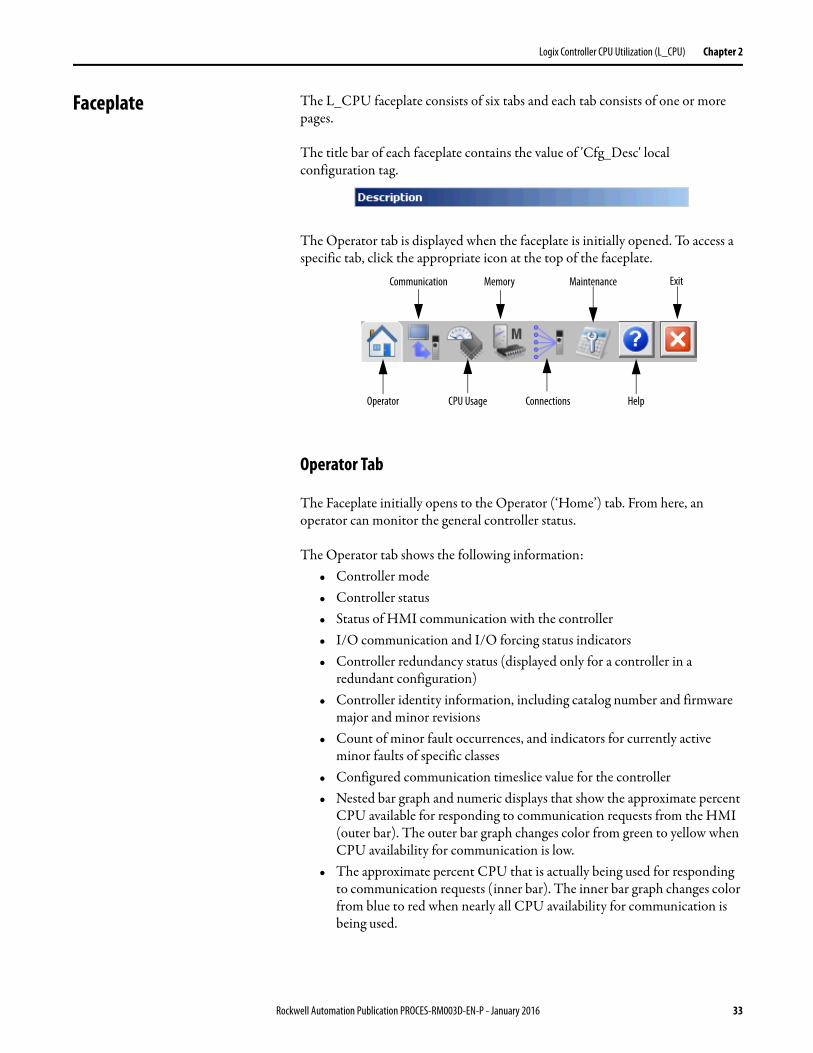
Faceplate The L_CPU faceplate consists of six tabs and each tab consists of one or more pages.
The title bar of each faceplate contains the value of 'Cfg_Desc' local configuration tag.
The Operator tab is displayed when the faceplate is initially opened. To access a specific tab, click the appropriate icon at the top of the faceplate.
Operator Tab
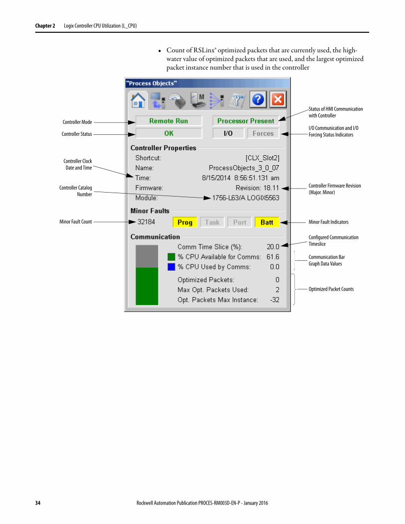
The Faceplate initially opens to the Operator (‘Home’) tab. From here, an operator can monitor the general controller status.
The Operator tab shows the following information:• Controller mode• Controller status• Status of HMI communication with the controller• I/O communication and I/O forcing status indicators• Controller redundancy status (displayed only for a controller in a
redundant configuration)• Controller identity information, including catalog number and firmware
major and minor revisions• Count of minor fault occurrences, and indicators for currently active
minor faults of specific classes• Configured communication timeslice value for the controller• Nested bar graph and numeric displays that show the approximate percent
CPU available for responding to communication requests from the HMI (outer bar). The outer bar graph changes color from green to yellow when CPU availability for communication is low.
• The approximate percent CPU that is actually being used for responding to communication requests (inner bar). The inner bar graph changes color from blue to red when nearly all CPU availability for communication is being used.
Operator CPU Usage
Communication
Connections
Memory
Help
ExitMaintenance
Rockwell Automation Publication PROCES-RM003D-EN-P - January 2016 33
Chapter 2 Logix Controller CPU Utilization (L_CPU)
• Count of RSLinx® optimized packets that are currently used, the high-water value of optimized packets that are used, and the largest optimized packet instance number that is used in the controller
Controller Mode
Status of HMI Communication with Controller
I/O Communication and I/O Forcing Status Indicators
Controller Firmware Revision (Major. Minor)
Minor Fault Indicators
Optimized Packet Counts
Controller Status
Controller Clock Date and Time
Minor Fault Count
Communication Bar Graph Data Values
Configured Communication Timeslice
Controller CatalogNumber
34 Rockwell Automation Publication PROCES-RM003D-EN-P - January 2016
Logix Controller CPU Utilization (L_CPU) Chapter 2
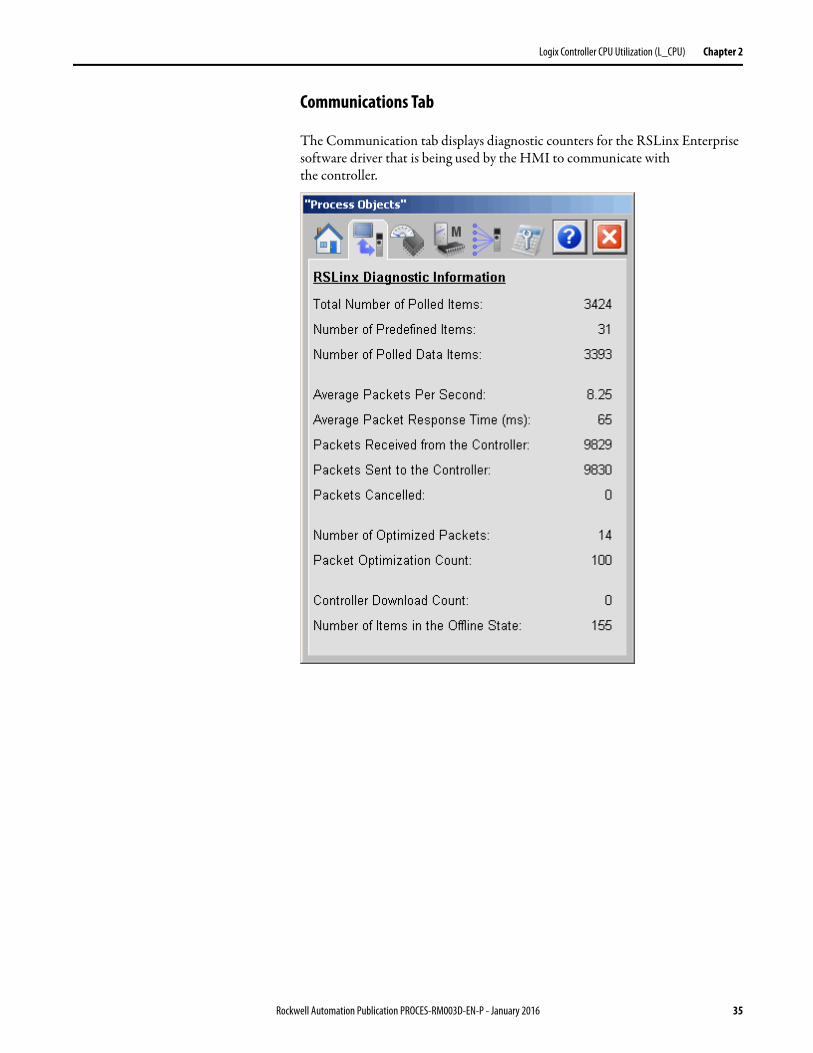
Communications Tab
The Communication tab displays diagnostic counters for the RSLinx Enterprise software driver that is being used by the HMI to communicate with the controller.
Rockwell Automation Publication PROCES-RM003D-EN-P - January 2016 35
Chapter 2 Logix Controller CPU Utilization (L_CPU)
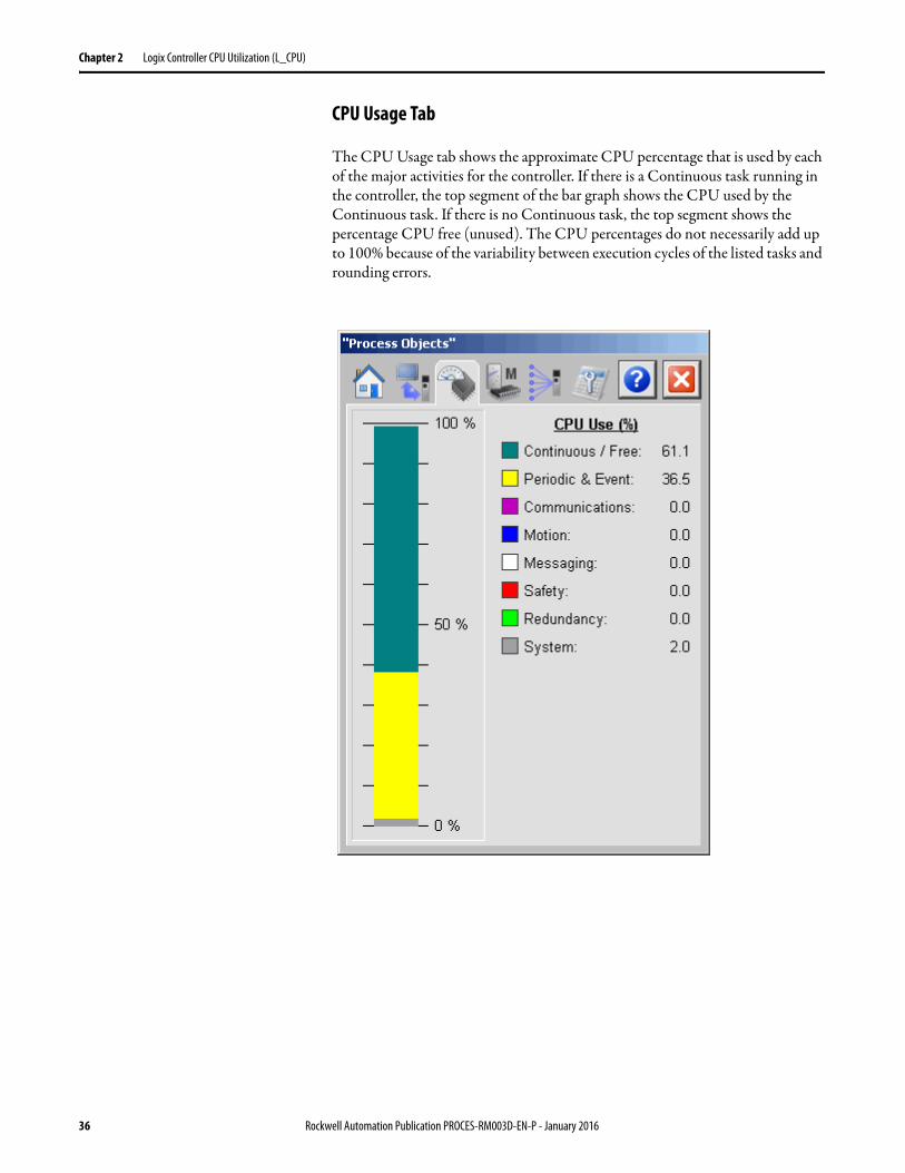
CPU Usage Tab
The CPU Usage tab shows the approximate CPU percentage that is used by each of the major activities for the controller. If there is a Continuous task running in the controller, the top segment of the bar graph shows the CPU used by the Continuous task. If there is no Continuous task, the top segment shows the percentage CPU free (unused). The CPU percentages do not necessarily add up to 100% because of the variability between execution cycles of the listed tasks and rounding errors.
36 Rockwell Automation Publication PROCES-RM003D-EN-P - January 2016
Logix Controller CPU Utilization (L_CPU) Chapter 2
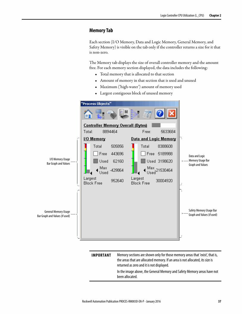
Memory Tab
Each section (I/O Memory, Data and Logic Memory, General Memory, and Safety Memory) is visible on the tab only if the controller returns a size for it that is non-zero.
The Memory tab displays the size of overall controller memory and the amount free. For each memory section displayed, the data includes the following:
• Total memory that is allocated to that section• Amount of memory in that section that is used and unused• Maximum (‘high-water’) amount of memory used• Largest contiguous block of unused memory
Data and Logic Memory Usage Bar Graph and Values
I/O Memory UsageBar Graph and Values
General Memory UsageBar Graph and Values (if used)
Safety Memory Usage Bar Graph and Values (if used)
IMPORTANT Memory sections are shown only for those memory areas that 'exist', that is, the areas that are allocated memory. If an area is not allocated, its size is returned as zero and it is not displayed.In the image above, the General Memory and Safety Memory areas have not been allocated.
Rockwell Automation Publication PROCES-RM003D-EN-P - January 2016 37
Chapter 2 Logix Controller CPU Utilization (L_CPU)
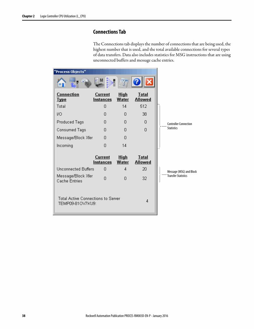
Connections Tab
The Connections tab displays the number of connections that are being used, the highest number that is used, and the total available connections for several types of data transfers. Data also includes statistics for MSG instructions that are using unconnected buffers and message cache entries.
Controller Connection Statistics
Message (MSG) and Block Transfer Statistics
38 Rockwell Automation Publication PROCES-RM003D-EN-P - January 2016
Logix Controller CPU Utilization (L_CPU) Chapter 2
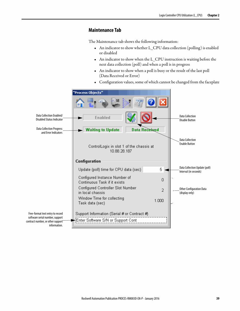
Maintenance Tab
The Maintenance tab shows the following information:• An indicator to show whether L_CPU data collection (polling) is enabled
or disabled• An indicator to show when the L_CPU instruction is waiting before the
next data collection (poll) and when a poll is in progress• An indicator to show when a poll is busy or the result of the last poll
(Data Received or Error)• Configuration values, some of which cannot be changed from the faceplate
Data Collection Enabled/Disabled Status Indicator
Data Collection Progressand Error Indicators
Data Collection Disable Button
Data Collection Update (poll) Interval (in seconds)
Other Configuration Data (display only)
Free-format text entry to recordsoftware serial number, support
contract number, or other supportinformation.
Data Collection Enable Button
Rockwell Automation Publication PROCES-RM003D-EN-P - January 2016 39
Chapter 2 Logix Controller CPU Utilization (L_CPU)
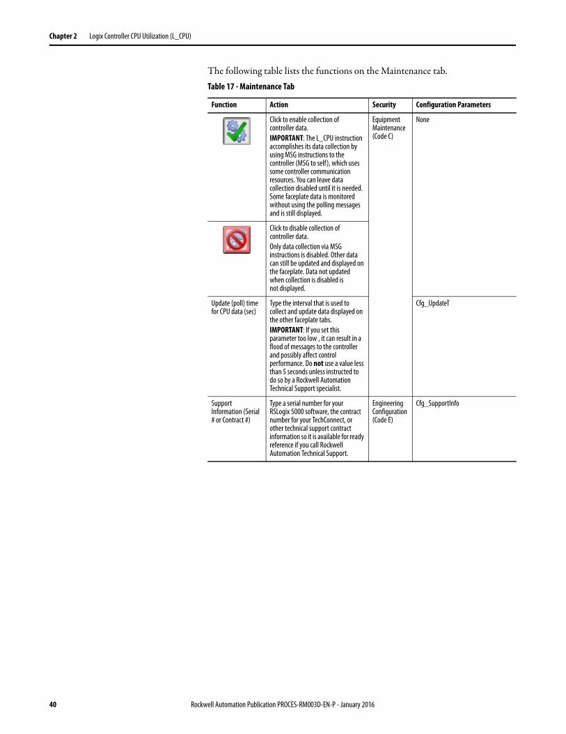
The following table lists the functions on the Maintenance tab.Table 17 - Maintenance Tab
Function Action Security Configuration Parameters
Click to enable collection of controller data.IMPORTANT: The L_CPU instruction accomplishes its data collection by using MSG instructions to the controller (MSG to self), which uses some controller communication resources. You can leave data collection disabled until it is needed. Some faceplate data is monitored without using the polling messages and is still displayed.
Equipment Maintenance (Code C)
None
Click to disable collection of controller data.Only data collection via MSG instructions is disabled. Other data can still be updated and displayed on the faceplate. Data not updated when collection is disabled is not displayed.
Update (poll) time for CPU data (sec)
Type the interval that is used to collect and update data displayed on the other faceplate tabs.IMPORTANT: If you set this parameter too low , it can result in a flood of messages to the controller and possibly affect control performance. Do not use a value less than 5 seconds unless instructed to do so by a Rockwell Automation Technical Support specialist.
Cfg_UpdateT
Support Information (Serial # or Contract #)
Type a serial number for yourRSLogix 5000 software, the contract number for your TechConnect, or other technical support contract information so it is available for ready reference if you call Rockwell Automation Technical Support.
Engineering Configuration (Code E)
Cfg_SupportInfo
40 Rockwell Automation Publication PROCES-RM003D-EN-P - January 2016
Logix Controller CPU Utilization (L_CPU) Chapter 2
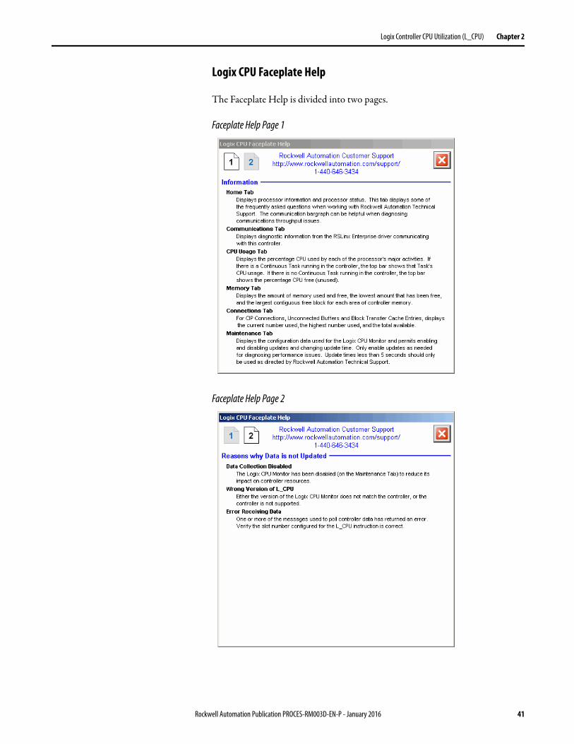
Logix CPU Faceplate Help
The Faceplate Help is divided into two pages.
Faceplate Help Page 1
Faceplate Help Page 2
Rockwell Automation Publication PROCES-RM003D-EN-P - January 2016 41

Chapter 2 Logix Controller CPU Utilization (L_CPU)
Notes:
42 Rockwell Automation Publication PROCES-RM003D-EN-P - January 2016
Chapter 3
Logix Redundant Controller Monitor (L_Redun)
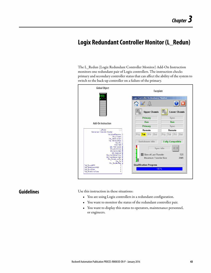
The L_Redun (Logix Redundant Controller Monitor) Add-On Instruction monitors one redundant pair of Logix controllers. The instruction checks primary and secondary controller status that can affect the ability of the system to switch to the back-up controller on a failure of the primary.
Guidelines Use this instruction in these situations:• You are using Logix controllers in a redundant configuration.• You want to monitor the status of the redundant controller pair.• You want to display this status to operators, maintenance personnel,
or engineers.
Global Object
Add-On Instruction
Faceplate
Rockwell Automation Publication PROCES-RM003D-EN-P - January 2016 43
Chapter 3 Logix Redundant Controller Monitor (L_Redun)
Do not use this instruction in these situations:• You are using single Logix controllers, not in a redundant configuration.
The L_Redun instruction is designed around the ControlLogix Enhanced Redundancy System architecture, by using information from the 1756-RM2 Redundancy Modules. The L_Redun Add-On Instruction does not verify in a non-redundant system because the data items it monitors do not exist in a non-redundant configuration.
• Your controllers are in an accessible location and the indicators on the controllers, network modules, and redundancy modules provide sufficient information about redundancy status.
For more information, see the ControlLogix Enhanced Redundancy System User Manual, publication 1756-UM535.
Functional Description The L_Redun instruction is provided as a rung import for installation. Importing this rung into your Ladder Diagram routine:
• imports the Add-On Instruction definition• creates an instruction instance• creates and completes all required tags and data structures for the
instruction
Once the rung is imported, and before you download and run the application, set the path in each Message tag that is referenced by the input/output parameters of the instruction to point to slot that contains the 1756-RM2 module in the local chassis ('1, <slot>').
Required Files Add-On Instructions are reusable code objects that contain encapsulated logic that can streamline implementing your system. This code lets you create your own instruction set for programming logic as a supplement to the instruction set provided natively in the ControlLogix firmware. An Add-On Instruction is defined once in each controller project, and can be instantiated multiple times in your application code as needed.
Controller File
The L_Redun_3_5-00_RUNG.L5X rung import file must be imported into the controller project to be able to be used in the controller configuration. The service release number (boldfaced) can change as service revisions are created.
The import file is available from the Product Compatibility and Download Center at http://www.rockwellautomation.com/rockwellautomation/support/pcdc.page.
44 Rockwell Automation Publication PROCES-RM003D-EN-P - January 2016

Logix Redundant Controller Monitor (L_Redun) Chapter 3
Visualization Files
The Process Library contains visualization files for built-in firmware instructions which provide a common user interface. These files can be downloaded from the Product Compatibility and Download Center at http://www.rockwellautomation.com/global/support/pcdc.page.
This Add-On Instruction has associated visualization files that provide a common user interface. These files can be downloaded from the Product Compatibility and Download Center at http://www.rockwellautomation.com/rockwellautomation/support/pcdc.page.
Images are external graphic files that can be used in displays. They must be imported for FactoryTalk View to make use of them.
When PNG files are imported, they are renamed by FactoryTalk View with a .bmp file extension, but retain a .png format.
The Global Object files (.ggfx file type) in the following table are Process Library display elements that are created once and referenced multiple times on multiple displays in an application. When changes are made to a Global Object, all instances in the application are automatically updated.
IMPORTANT The visualization file dependencies require Process Library content imports to occur in a specific order as reflected in the following tables:• Images• Global Objects• Standard Displays• HMI Tags• Macros
Table 18 - Visualization Files: Images (.png)
FactoryTalk View SE Software FactoryTalk View ME Software Description
All .png files in the images folder All .png files in the images folder These are the common icons used in the global objects and standard displays for all Process Objects.
Table 19 - Visualization Files: Global Objects (.ggfx)
FactoryTalk View SE Software FactoryTalk View ME Software Description
(RA-BAS) BuiltIn Faceplate Objects (RA-BAS-ME) BuiltIn Faceplate Objects Global objects for built-in instruction faceplates.
(RA-BAS) BuiltIn Graphics Librarys (RA-BAS-ME) BuiltIn Graphics Librarys Global object device symbols used to build built-in instruction graphics.
(RA-BAS) BuiltIn Help Objects (RA-BAS-ME) BuiltIn Help Objects Global objects for built-in instruction Help displays.
(RA-BAS) Common Faceplate Objects (RA-BAS-ME) Common Faceplate Objects Global objects used on process object faceplates.
(RA-BAS) Logix Faceplate Objects (RA-BAS-ME) Logix Faceplate Objects Global objects used on Logix faceplates.
(RA-BAS) Logix Graphics Library (RA-BAS-ME) Logix Graphics Library Global object device symbols used to build displays for all Logix Objects.
(RA-BAS) Process Alarm Objects (RA-BAS-ME) Process Alarm Objects Global objects used for managing alarms on process object faceplates.
Rockwell Automation Publication PROCES-RM003D-EN-P - January 2016 45
Chapter 3 Logix Redundant Controller Monitor (L_Redun)
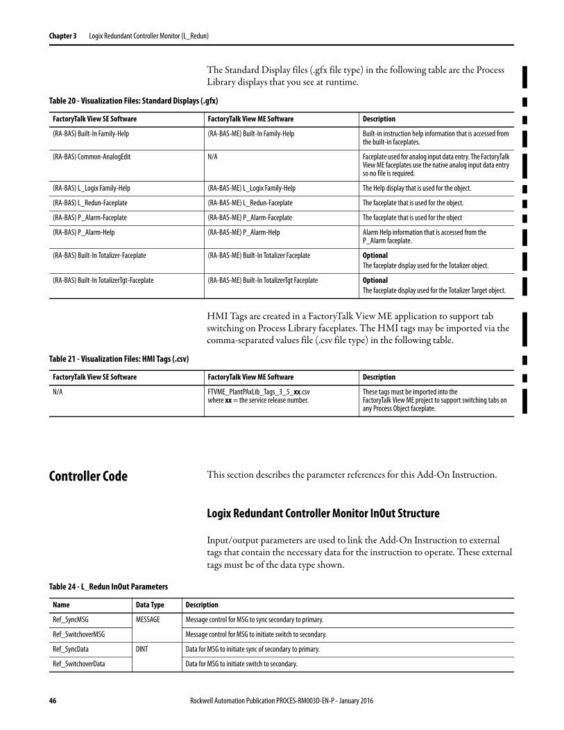
The Standard Display files (.gfx file type) in the following table are the Process Library displays that you see at runtime.
HMI Tags are created in a FactoryTalk View ME application to support tab switching on Process Library faceplates. The HMI tags may be imported via the comma-separated values file (.csv file type) in the following table.
Controller Code This section describes the parameter references for this Add-On Instruction.
Logix Redundant Controller Monitor InOut Structure
Input/output parameters are used to link the Add-On Instruction to external tags that contain the necessary data for the instruction to operate. These external tags must be of the data type shown.
Table 20 - Visualization Files: Standard Displays (.gfx)
FactoryTalk View SE Software FactoryTalk View ME Software Description
(RA-BAS) Built-In Family-Help (RA-BAS-ME) Built-In Family-Help Built-in instruction help information that is accessed from the built-in faceplates.
(RA-BAS) Common-AnalogEdit N/A Faceplate used for analog input data entry. The FactoryTalk View ME faceplates use the native analog input data entry so no file is required.
(RA-BAS) L_Logix Family-Help (RA-BAS-ME) L_Logix Family-Help The Help display that is used for the object.
(RA-BAS) L_Redun-Faceplate (RA-BAS-ME) L_Redun-Faceplate The faceplate that is used for the object.
(RA-BAS) P_Alarm-Faceplate (RA-BAS-ME) P_Alarm-Faceplate The faceplate that is used for the object
(RA-BAS) P_Alarm-Help (RA-BAS-ME) P_Alarm-Help Alarm Help information that is accessed from the P_AIarm faceplate.
(RA-BAS) Built-In Totalizer-Faceplate (RA-BAS-ME) Built-In Totalizer Faceplate OptionalThe faceplate display used for the Totalizer object.
(RA-BAS) Built-In TotalizerTgt-Faceplate (RA-BAS-ME) Built-In TotalizerTgt Faceplate OptionalThe faceplate display used for the Totalizer Target object.
Table 21 - Visualization Files: HMI Tags (.csv)
FactoryTalk View SE Software FactoryTalk View ME Software Description
N/A FTVME_PlantPAxLib_Tags_3_5_xx.csvwhere xx = the service release number.
These tags must be imported into theFactoryTalk View ME project to support switching tabs on any Process Object faceplate.
Table 24 - L_Redun InOut Parameters
Name Data Type Description
Ref_SyncMSG MESSAGE Message control for MSG to sync secondary to primary.
Ref_SwitchoverMSG Message control for MSG to initiate switch to secondary.
Ref_SyncData DINT Data for MSG to initiate sync of secondary to primary.
Ref_SwitchoverData Data for MSG to initiate switch to secondary.
46 Rockwell Automation Publication PROCES-RM003D-EN-P - January 2016
Logix Redundant Controller Monitor (L_Redun) Chapter 3
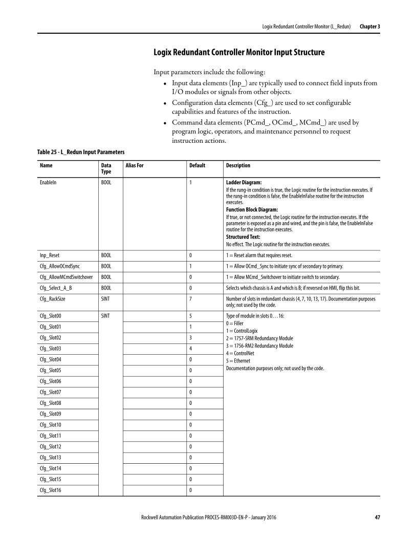
Logix Redundant Controller Monitor Input Structure
Input parameters include the following:• Input data elements (Inp_) are typically used to connect field inputs from
I/O modules or signals from other objects.• Configuration data elements (Cfg_) are used to set configurable
capabilities and features of the instruction.• Command data elements (PCmd_, OCmd_, MCmd_) are used by
program logic, operators, and maintenance personnel to request instruction actions.
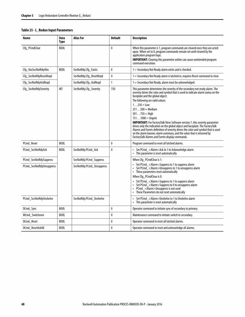
Table 25 - L_Redun Input Parameters
Name Data Type
Alias For Default Description
EnableIn BOOL 1 Ladder Diagram:If the rung-in condition is true, the Logic routine for the instruction executes. If the rung-in condition is false, the EnableInFalse routine for the instruction executes.Function Block Diagram:If true, or not connected, the Logic routine for the instruction executes. If the parameter is exposed as a pin and wired, and the pin is false, the EnableInFalse routine for the instruction executes.Structured Text:No effect. The Logic routine for the instruction executes.
Inp_Reset BOOL 0 1 = Reset alarm that requires reset.
Cfg_AllowOCmdSync BOOL 1 1 = Allow OCmd_Sync to initiate sync of secondary to primary.
Cfg_AllowMCmdSwitchover BOOL 0 1 = Allow MCmd_Switchover to initiate switch to secondary.
Cfg_Select_A_B BOOL 0 Selects which chassis is A and which is B; if reversed on HMI, flip this bit.
Cfg_RackSize SINT 7 Number of slots in redundant chassis (4, 7, 10, 13, 17). Documentation purposes only; not used by the code.
Cfg_Slot00 SINT 5 Type of module in slots 0…16:0 = Filler1 = ControlLogix2 = 1757-SRM Redundancy Module3 = 1756-RM2 Redundancy Module4 = ControlNet5 = EthernetDocumentation purposes only; not used by the code.
Cfg_Slot01 1
Cfg_Slot02 3
Cfg_Slot03 4
Cfg_Slot04 0
Cfg_Slot05 0
Cfg_Slot06 0
Cfg_Slot07 0
Cfg_Slot08 0
Cfg_Slot09 0
Cfg_Slot10 0
Cfg_Slot11 0
Cfg_Slot12 0
Cfg_Slot13 0
Cfg_Slot14 0
Cfg_Slot15 0
Cfg_Slot16 0
Rockwell Automation Publication PROCES-RM003D-EN-P - January 2016 47
Chapter 3 Logix Redundant Controller Monitor (L_Redun)
Cfg_PCmdClear BOOL 0 When this parameter is 1, program commands are cleared once they are acted upon. When set to 0, program commands remain set until cleared by the application program logic.IMPORTANT: Clearing this parameter online can cause unintended program command execution.
Cfg_HasSecNotRdyAlm BOOL SecNotRdy.Cfg_Exists 0 1 = Secondary Not Ready alarm exists and is checked.
Cfg_SecNotRdyResetReqd SecNotRdy.Cfg_ResetReqd 0 1 = Secondary Not Ready alarm is latched in, requires Reset command to clear.
Cfg_SecNotRdyAckReqd SecNotRdy.Cfg_AckReqd 1 1 = Secondary Not Ready, alarm must be acknowledged.
Cfg_SecNotRdySeverity INT SecNotRdy.Cfg_Severity 750 This parameter determines the severity of the secondary not ready alarm. The severity drives the color and symbol that is used to indicate alarm status on the faceplate and the global object. The following are valid values:1…250 = Low251…500 = Medium501…750 = High751…1000 = UrgentIMPORTANT: For FactoryTalk View Software version 7, this severity parameter drives only the indication on the global object and faceplate. The FactoryTalk Alarms and Events definition of severity drives the color and symbol that is used on the alarm banner, alarm summary, and the value that is returned by FactoryTalk Alarms and Events display commands.
PCmd_Reset BOOL 0 Program command to reset all latched alarms.
PCmd_SecNotRdyAck BOOL SecNotRdy.PCmd_Ack 0 • Set PCmd_<Alarm>Ack to 1 to Acknowledge alarm• This parameter is reset automatically
PCmd_SecNotRdySuppress SecNotRdy.PCmd_Suppress When Cfg_PCmdClear is 1:• Set PCmd_<Alarm>Suppress to 1 to suppress alarm• Set PCmd_<Alarm>Unsuppress to 1 to unsuppress alarm• These parameters reset automaticallyWhen Cfg_PCmdClear is 0:• Set PCmd_<Alarm>Suppress to 1 to suppress alarm• Set PCmd_<Alarm>Suppress to 0 to unsuppress alarm• PCmd_<Alarm>Unsuppress is not used • These Parameters do not reset automatically
PCmd_SecNotRdyUnsuppress SecNotRdy.PCmd_Unsuppress
PCmd_SecNotRdyUnshelve SecNotRdy.PCmd_Unshelve • Set PCmd_<Alarm>Unshelve to 1 to Unshelve alarm• This parameter is reset automatically
OCmd_Sync BOOL 0 Operator command to initiate sync of secondary to primary.
MCmd_Switchover BOOL 0 Maintenance command to initiate switch to secondary.
OCmd_Reset BOOL 0 Operator command to reset all latched alarms.
OCmd_ResetAckAll BOOL 0 Operator command to reset and acknowledge all alarms.
Table 25 - L_Redun Input Parameters
Name Data Type
Alias For Default Description
48 Rockwell Automation Publication PROCES-RM003D-EN-P - January 2016
Logix Redundant Controller Monitor (L_Redun) Chapter 3
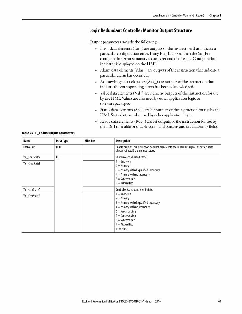
Logix Redundant Controller Monitor Output Structure
Output parameters include the following:• Error data elements (Err_) are outputs of the instruction that indicate a
particular configuration error. If any Err_ bit is set, then the Sts_Err configuration error summary status is set and the Invalid Configuration indicator is displayed on the HMI.
• Alarm data elements (Alm_) are outputs of the instruction that indicate a particular alarm has occurred.
• Acknowledge data elements (Ack_) are outputs of the instruction that indicate the corresponding alarm has been acknowledged.
• Value data elements (Val_) are numeric outputs of the instruction for use by the HMI. Values are also used by other application logic or software packages.
• Status data elements (Sts_) are bit outputs of the instruction for use by the HMI. Status bits are also used by other application logic.
• Ready data elements (Rdy_) are bit outputs of the instruction for use by the HMI to enable or disable command buttons and set data entry fields.
Table 26 - L_Redun Output Parameters
Name Data Type Alias For Description
EnableOut BOOL Enable output: This instruction does not manipulate the EnableOut signal. Its output state always reflects EnableIn Input state.
Val_ChasStateA INT Chassis A and chassis B state: 1 = Unknown2 = Primary3 = Primary with disqualified secondary4 = Primary with no secondary8 = Synchronized9 = Disqualified
Val_ChasStateB
Val_CtrlrStateA Controller A and controller B state: 1 = Unknown2 = Primary3 = Primary with disqualified secondary4 = Primary with no secondary6 = Synchronizing7 = Synchronizing8 = Synchronized9 = Disqualified14 = None
Val_CtrlrStateB
Rockwell Automation Publication PROCES-RM003D-EN-P - January 2016 49
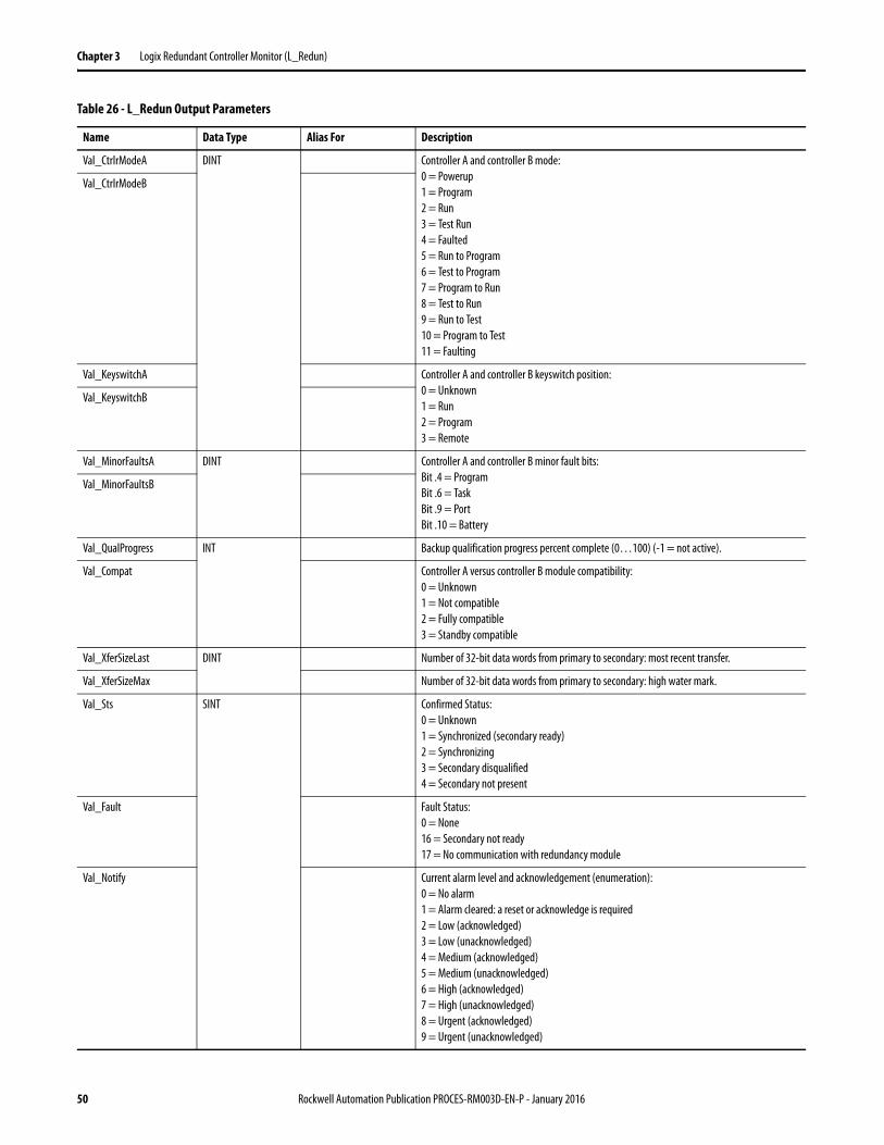
Chapter 3 Logix Redundant Controller Monitor (L_Redun)
Val_CtrlrModeA DINT Controller A and controller B mode: 0 = Powerup1 = Program2 = Run3 = Test Run4 = Faulted5 = Run to Program6 = Test to Program7 = Program to Run8 = Test to Run9 = Run to Test10 = Program to Test11 = Faulting
Val_CtrlrModeB
Val_KeyswitchA Controller A and controller B keyswitch position: 0 = Unknown1 = Run2 = Program3 = Remote
Val_KeyswitchB
Val_MinorFaultsA DINT Controller A and controller B minor fault bits: Bit .4 = ProgramBit .6 = TaskBit .9 = PortBit .10 = Battery
Val_MinorFaultsB
Val_QualProgress INT Backup qualification progress percent complete (0…100) (-1 = not active).
Val_Compat Controller A versus controller B module compatibility: 0 = Unknown1 = Not compatible2 = Fully compatible3 = Standby compatible
Val_XferSizeLast DINT Number of 32-bit data words from primary to secondary: most recent transfer.
Val_XferSizeMax Number of 32-bit data words from primary to secondary: high water mark.
Val_Sts SINT Confirmed Status:0 = Unknown1 = Synchronized (secondary ready)2 = Synchronizing3 = Secondary disqualified4 = Secondary not present
Val_Fault Fault Status:0 = None16 = Secondary not ready17 = No communication with redundancy module
Val_Notify Current alarm level and acknowledgement (enumeration):0 = No alarm1 = Alarm cleared: a reset or acknowledge is required2 = Low (acknowledged)3 = Low (unacknowledged)4 = Medium (acknowledged)5 = Medium (unacknowledged)6 = High (acknowledged)7 = High (unacknowledged)8 = Urgent (acknowledged)9 = Urgent (unacknowledged)
Table 26 - L_Redun Output Parameters
Name Data Type Alias For Description
50 Rockwell Automation Publication PROCES-RM003D-EN-P - January 2016
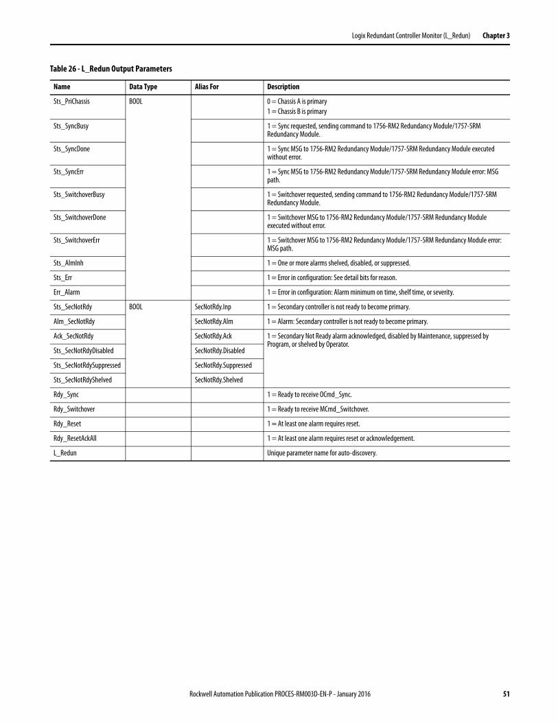
Logix Redundant Controller Monitor (L_Redun) Chapter 3
Sts_PriChassis BOOL 0 = Chassis A is primary1 = Chassis B is primary
Sts_SyncBusy 1 = Sync requested, sending command to 1756-RM2 Redundancy Module/1757-SRM Redundancy Module.
Sts_SyncDone 1 = Sync MSG to 1756-RM2 Redundancy Module/1757-SRM Redundancy Module executed without error.
Sts_SyncErr 1 = Sync MSG to 1756-RM2 Redundancy Module/1757-SRM Redundancy Module error: MSG path.
Sts_SwitchoverBusy 1 = Switchover requested, sending command to 1756-RM2 Redundancy Module/1757-SRM Redundancy Module.
Sts_SwitchoverDone 1 = Switchover MSG to 1756-RM2 Redundancy Module/1757-SRM Redundancy Module executed without error.
Sts_SwitchoverErr 1 = Switchover MSG to 1756-RM2 Redundancy Module/1757-SRM Redundancy Module error: MSG path.
Sts_AlmInh 1 = One or more alarms shelved, disabled, or suppressed.
Sts_Err 1 = Error in configuration: See detail bits for reason.
Err_Alarm 1 = Error in configuration: Alarm minimum on time, shelf time, or severity.
Sts_SecNotRdy BOOL SecNotRdy.Inp 1 = Secondary controller is not ready to become primary.
Alm_SecNotRdy SecNotRdy.Alm 1 = Alarm: Secondary controller is not ready to become primary.
Ack_SecNotRdy SecNotRdy.Ack 1 = Secondary Not Ready alarm acknowledged, disabled by Maintenance, suppressed by Program, or shelved by Operator.
Sts_SecNotRdyDisabled SecNotRdy.Disabled
Sts_SecNotRdySuppressed SecNotRdy.Suppressed
Sts_SecNotRdyShelved SecNotRdy.Shelved
Rdy_Sync 1 = Ready to receive OCmd_Sync.
Rdy_Switchover 1 = Ready to receive MCmd_Switchover.
Rdy_Reset 1 = At least one alarm requires reset.
Rdy_ResetAckAll 1 = At least one alarm requires reset or acknowledgement.
L_Redun Unique parameter name for auto-discovery.
Table 26 - L_Redun Output Parameters
Name Data Type Alias For Description
Rockwell Automation Publication PROCES-RM003D-EN-P - January 2016 51
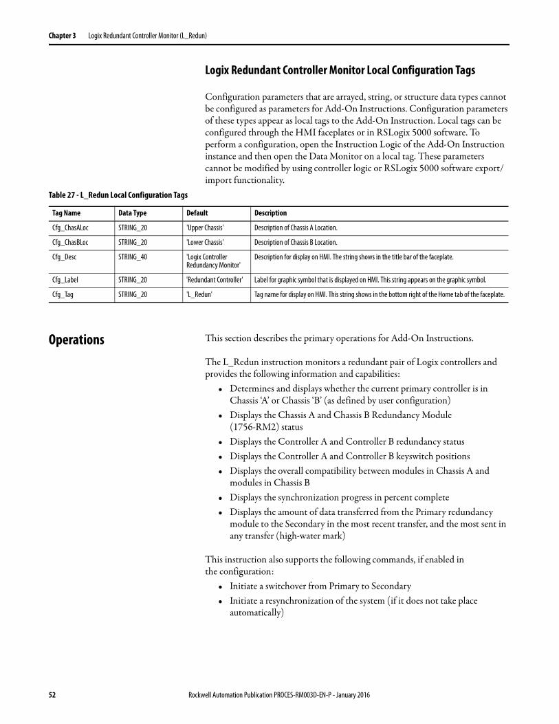
Chapter 3 Logix Redundant Controller Monitor (L_Redun)
Logix Redundant Controller Monitor Local Configuration Tags
Configuration parameters that are arrayed, string, or structure data types cannot be configured as parameters for Add-On Instructions. Configuration parameters of these types appear as local tags to the Add-On Instruction. Local tags can be configured through the HMI faceplates or in RSLogix 5000 software. To perform a configuration, open the Instruction Logic of the Add-On Instruction instance and then open the Data Monitor on a local tag. These parameters cannot be modified by using controller logic or RSLogix 5000 software export/import functionality.
Operations This section describes the primary operations for Add-On Instructions.
The L_Redun instruction monitors a redundant pair of Logix controllers and provides the following information and capabilities:
• Determines and displays whether the current primary controller is in Chassis ‘A’ or Chassis ‘B’ (as defined by user configuration)
• Displays the Chassis A and Chassis B Redundancy Module(1756-RM2) status
• Displays the Controller A and Controller B redundancy status• Displays the Controller A and Controller B keyswitch positions• Displays the overall compatibility between modules in Chassis A and
modules in Chassis B• Displays the synchronization progress in percent complete• Displays the amount of data transferred from the Primary redundancy
module to the Secondary in the most recent transfer, and the most sent in any transfer (high-water mark)
This instruction also supports the following commands, if enabled in the configuration:
• Initiate a switchover from Primary to Secondary• Initiate a resynchronization of the system (if it does not take place
automatically)
Table 27 - L_Redun Local Configuration Tags
Tag Name Data Type Default Description
Cfg_ChasALoc STRING_20 'Upper Chassis' Description of Chassis A Location.
Cfg_ChasBLoc STRING_20 'Lower Chassis' Description of Chassis B Location.
Cfg_Desc STRING_40 'Logix Controller Redundancy Monitor'
Description for display on HMI. The string shows in the title bar of the faceplate.
Cfg_Label STRING_20 'Redundant Controller' Label for graphic symbol that is displayed on HMI. This string appears on the graphic symbol.
Cfg_Tag STRING_20 'L_Redun' Tag name for display on HMI. This string shows in the bottom right of the Home tab of the faceplate.
52 Rockwell Automation Publication PROCES-RM003D-EN-P - January 2016
Logix Redundant Controller Monitor (L_Redun) Chapter 3
Modes
The L_Redun instruction has no commands or outputs intended to control equipment and so does not have any modes.
Alarm
The L_Redun Instruction uses the following alarm, which is implemented by using an embedded P_Alarm Add-On Instruction.
See the Rockwell Automation Library of Process Objects: Common Alarm Block (P_Alarm) Reference Manual, publication SYSLIB-RM002, for more information.
Simulation
The L_Redun Add-On Instruction does not have a Simulation capability.
Execution
The following table explains the handling of instruction execution conditions.
See the Logix5000 Controllers Add-On Instructions Programming Manual, publication 1756-PM010, for more information.
Alarm P_Alarm Name Description
Secondary not ready
SecNotRdy Secondary Controller Not Ready alarm
Table 28 - L_Redun Execution Conditions
Condition Description
EnableIn False (false rung) No EnableIn False logic is provided. The L_Redun instruction must always be scanned true. In relay ladder logic, the L_Redun instruction must be by itself on an unconditional rung. If the Rung Import provided with the Rockwell Automation is used to install this instruction, the proper rung is created for you.
Powerup (prescan, first scan) On Pre-scan, any commands that are received before first scan are discarded.
Postscan (SFC transition) No SFC Postscan logic is provided.
Rockwell Automation Publication PROCES-RM003D-EN-P - January 2016 53
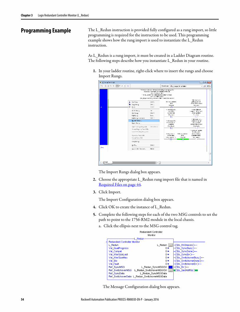
Chapter 3 Logix Redundant Controller Monitor (L_Redun)
Programming Example The L_Redun instruction is provided fully configured as a rung import, so little programming is required for the instruction to be used. This programming example shows how the rung import is used to instantiate the L_Redun instruction.
As L_Redun is a rung import, it must be created in a Ladder Diagram routine. The following steps describe how you instantiate L_Redun in your routine.
1. In your ladder routine, right-click where to insert the rungs and choose Import Rungs.
The Import Rungs dialog box appears.
2. Choose the appropriate L_Redun rung import file that is named inRequired Files on page 44.
3. Click Import.
The Import Configuration dialog box appears.
4. Click OK to create the instance of L_Redun.
5. Complete the following steps for each of the two MSG controls to set the path to point to the 1756-RM2 module in the local chassis.a. Click the ellipsis next to the MSG control tag.
The Message Configuration dialog box appears.
54 Rockwell Automation Publication PROCES-RM003D-EN-P - January 2016
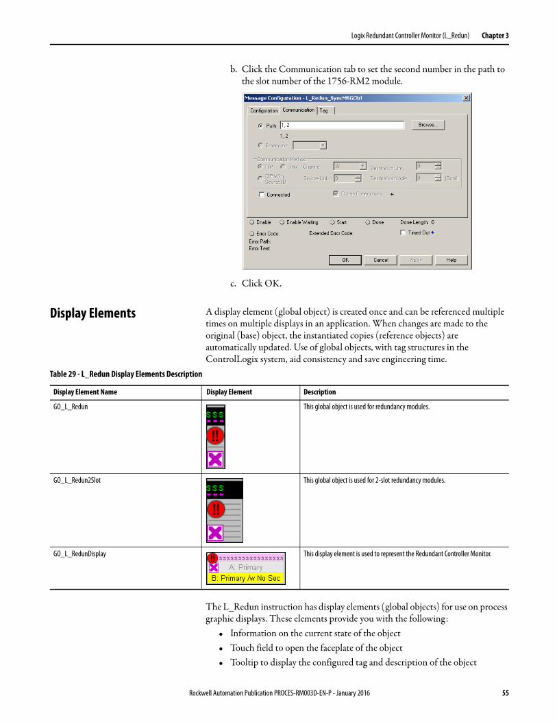
Logix Redundant Controller Monitor (L_Redun) Chapter 3
b. Click the Communication tab to set the second number in the path to the slot number of the 1756-RM2 module.
c. Click OK.
Display Elements A display element (global object) is created once and can be referenced multiple times on multiple displays in an application. When changes are made to the original (base) object, the instantiated copies (reference objects) are automatically updated. Use of global objects, with tag structures in the ControlLogix system, aid consistency and save engineering time.
The L_Redun instruction has display elements (global objects) for use on process graphic displays. These elements provide you with the following:
• Information on the current state of the object• Touch field to open the faceplate of the object• Tooltip to display the configured tag and description of the object
Table 29 - L_Redun Display Elements Description
Display Element Name Display Element Description
GO_L_Redun This global object is used for redundancy modules.
GO_L_Redun2Slot This global object is used for 2-slot redundancy modules.
GO_L_RedunDisplay This display element is used to represent the Redundant Controller Monitor.
Rockwell Automation Publication PROCES-RM003D-EN-P - January 2016 55
Chapter 3 Logix Redundant Controller Monitor (L_Redun)
Status/Quality IndicatorsOne of these symbols appears to the left of the graphic symbol when the described condition is true.
For the L_Redun instruction, the Invalid Configuration indicator appears under the following conditions:
• The Alarm Minimum On time or Shelf time is set to a value less than zero or greater than 2,147,483 seconds.
• Alarm Severity is set to a value less than 1 or greater than 1000.
Graphic Symbol Description
Controller minor fault, shown on the Operator tab of the faceplate.
TIP When the Invalid Configuration indicator appears, you can find what configuration setting is invalid by following the indicators. Click the graphic symbol to open the faceplate. The Invalid Configuration indicator appears next to the appropriate tab at the top of the faceplate to help you in find the configuration error. Once you navigate to the tab, the misconfigured item is flagged with this indicator or appears in a magenta box.
56 Rockwell Automation Publication PROCES-RM003D-EN-P - January 2016
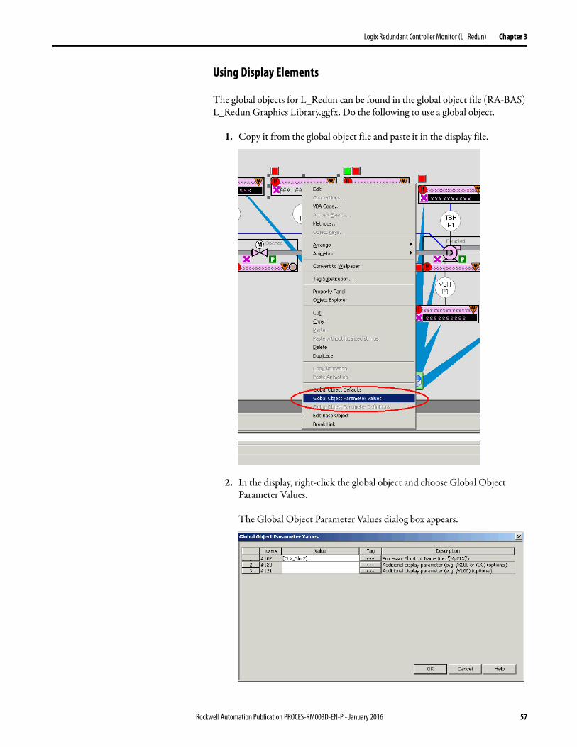
Logix Redundant Controller Monitor (L_Redun) Chapter 3
Using Display Elements
The global objects for L_Redun can be found in the global object file (RA-BAS) L_Redun Graphics Library.ggfx. Do the following to use a global object.
1. Copy it from the global object file and paste it in the display file.
2. In the display, right-click the global object and choose Global Object Parameter Values.
The Global Object Parameter Values dialog box appears.
Rockwell Automation Publication PROCES-RM003D-EN-P - January 2016 57
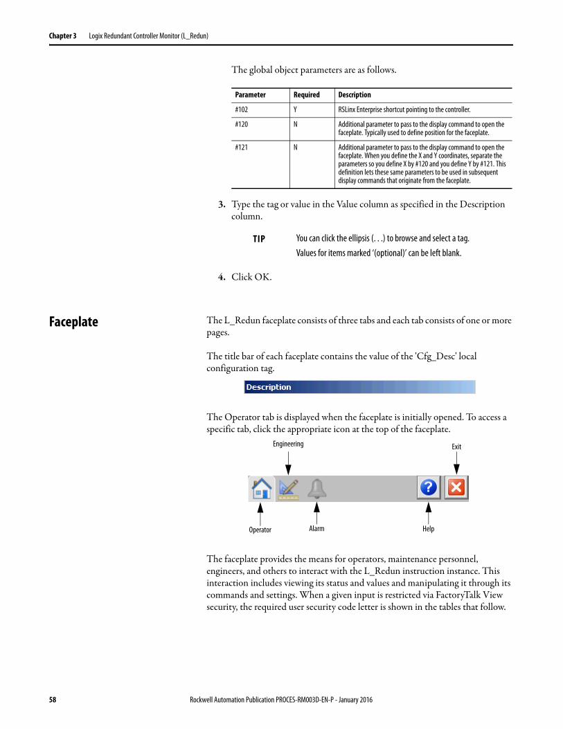
Chapter 3 Logix Redundant Controller Monitor (L_Redun)
The global object parameters are as follows.
3. Type the tag or value in the Value column as specified in the Description column.
4. Click OK.
Faceplate The L_Redun faceplate consists of three tabs and each tab consists of one or more pages.
The title bar of each faceplate contains the value of the 'Cfg_Desc' local configuration tag.
The Operator tab is displayed when the faceplate is initially opened. To access a specific tab, click the appropriate icon at the top of the faceplate.
The faceplate provides the means for operators, maintenance personnel, engineers, and others to interact with the L_Redun instruction instance. This interaction includes viewing its status and values and manipulating it through its commands and settings. When a given input is restricted via FactoryTalk View security, the required user security code letter is shown in the tables that follow.
Parameter Required Description
#102 Y RSLinx Enterprise shortcut pointing to the controller.
#120 N Additional parameter to pass to the display command to open the faceplate. Typically used to define position for the faceplate.
#121 N Additional parameter to pass to the display command to open the faceplate. When you define the X and Y coordinates, separate the parameters so you define X by #120 and you define Y by #121. This definition lets these same parameters to be used in subsequent display commands that originate from the faceplate.
TIP You can click the ellipsis (. . .) to browse and select a tag. Values for items marked ‘(optional)’ can be left blank.
Operator
Engineering
Alarm Help
Exit
58 Rockwell Automation Publication PROCES-RM003D-EN-P - January 2016
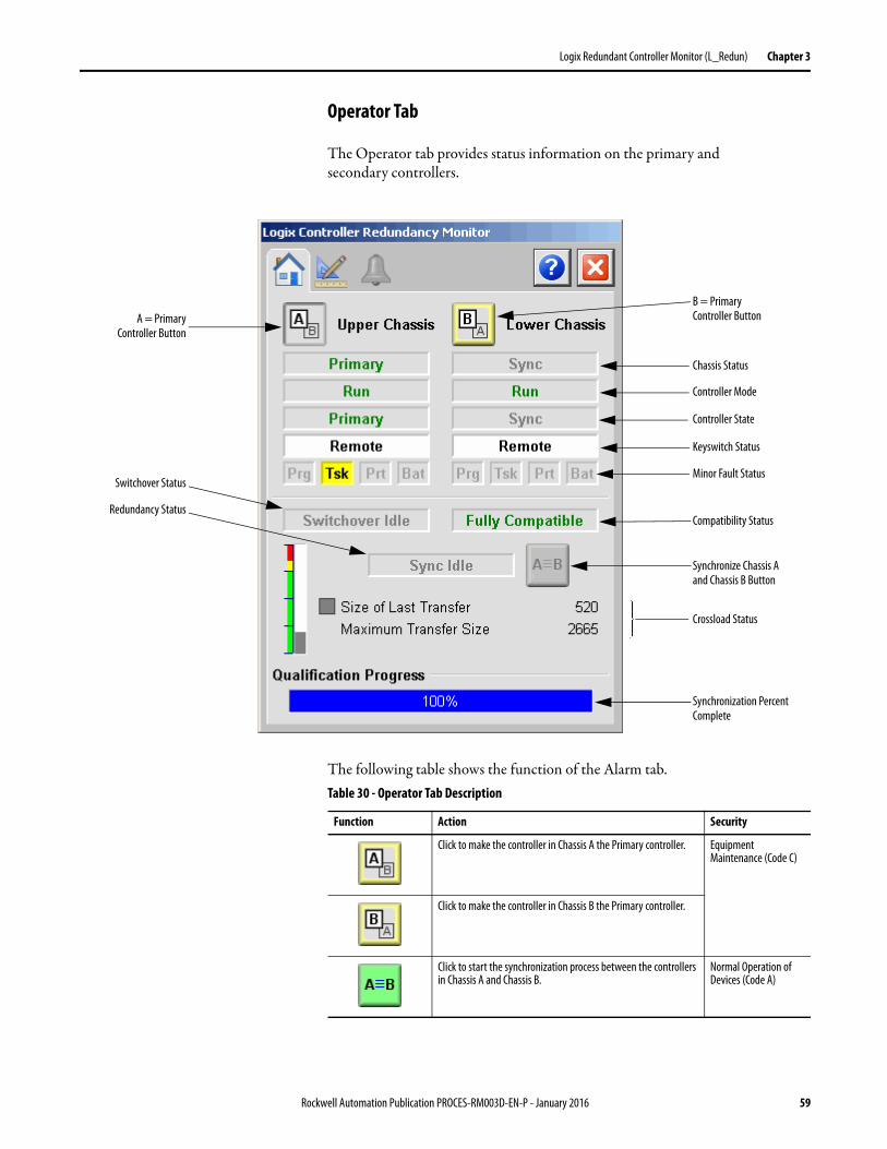
Logix Redundant Controller Monitor (L_Redun) Chapter 3
Operator Tab
The Operator tab provides status information on the primary and secondary controllers.
The following table shows the function of the Alarm tab.
Synchronize Chassis A and Chassis B Button
Chassis Status
Controller Mode
Controller State
Keyswitch Status
Minor Fault Status
Compatibility Status
Crossload Status
Synchronization Percent Complete
B = Primary Controller ButtonA = Primary
Controller Button
Redundancy Status
Switchover Status
Table 30 - Operator Tab Description
Function Action Security
Click to make the controller in Chassis A the Primary controller. Equipment Maintenance (Code C)
Click to make the controller in Chassis B the Primary controller.
Click to start the synchronization process between the controllers in Chassis A and Chassis B.
Normal Operation of Devices (Code A)
Rockwell Automation Publication PROCES-RM003D-EN-P - January 2016 59
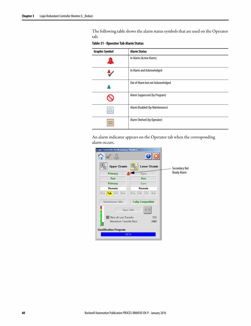
Chapter 3 Logix Redundant Controller Monitor (L_Redun)
The following table shows the alarm status symbols that are used on the Operator tab.
An alarm indicator appears on the Operator tab when the corresponding alarm occurs.
Table 31 - Operator Tab Alarm Status
Graphic Symbol Alarm Status
In Alarm (Active Alarm)
In Alarm and Acknowledged
Out of Alarm but not Acknowledged
Alarm Suppressed (by Program)
Alarm Disabled (by Maintenance)
Alarm Shelved (by Operator)
Secondary Not Ready Alarm
60 Rockwell Automation Publication PROCES-RM003D-EN-P - January 2016
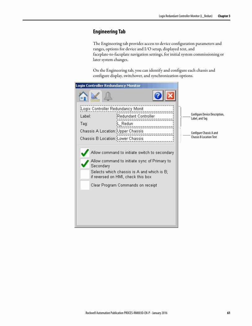
Logix Redundant Controller Monitor (L_Redun) Chapter 3
Engineering Tab
The Engineering tab provides access to device configuration parameters and ranges, options for device and I/O setup, displayed text, and faceplate-to-faceplate navigation settings, for initial system commissioning or later system changes.
On the Engineering tab, you can identify and configure each chassis and configure display, switchover, and synchronization options.
Configure Device Description, Label, and Tag
Configure Chassis A and Chassis B Location Text
Rockwell Automation Publication PROCES-RM003D-EN-P - January 2016 61
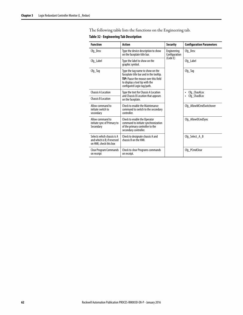
Chapter 3 Logix Redundant Controller Monitor (L_Redun)
The following table lists the functions on the Engineering tab.Table 32 - Engineering Tab Description
Function Action Security Configuration Parameters
Cfg_Desc Type the device description to show on the faceplate title bar.
Engineering Configuration (Code E)
Cfg_Desc
Cfg_Label Type the label to show on the graphic symbol.
Cfg_Label
Cfg_Tag Type the tag name to show on the faceplate title bar and in the tooltip.TIP: Pause the mouse over this field to display a tool tip with the configured Logix tag/path.
Cfg_Tag
Chassis A Location Type the text for Chassis A Location and Chassis B Location that appears on the faceplate.
• Cfg_ChasALoc• Cfg_ChasBLoc
Chassis B Location
Allow command to initiate switch to secondary
Check to enable the Maintenance command to switch to the secondary controller.
Cfg_AllowMCmdSwitchover
Allow command to initiate sync of Primary to Secondary
Check to enable the Operator command to initiate synchronization of the primary controller to the secondary controller.
Cfg_AllowOCmdSync
Selects which chassis is A and which is B; if reversed on HMI, check this box
Check to designate chassis A and chassis B on the HMI.
Cfg_Select_A_B
Clear Program Commands on receipt
Check to clear Programs commands on receipt.
Cfg_PCmdClear
62 Rockwell Automation Publication PROCES-RM003D-EN-P - January 2016
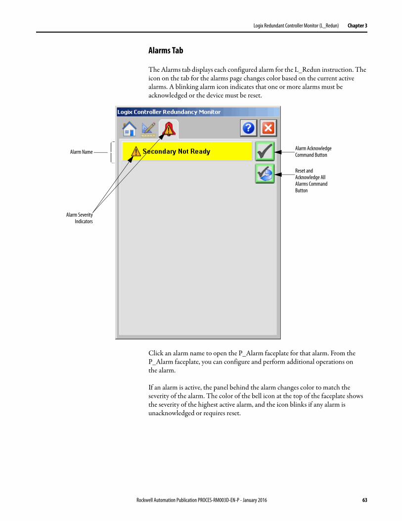
Logix Redundant Controller Monitor (L_Redun) Chapter 3
Alarms Tab
The Alarms tab displays each configured alarm for the L_Redun instruction. The icon on the tab for the alarms page changes color based on the current active alarms. A blinking alarm icon indicates that one or more alarms must be acknowledged or the device must be reset.
Click an alarm name to open the P_Alarm faceplate for that alarm. From the P_Alarm faceplate, you can configure and perform additional operations on the alarm.
If an alarm is active, the panel behind the alarm changes color to match the severity of the alarm. The color of the bell icon at the top of the faceplate shows the severity of the highest active alarm, and the icon blinks if any alarm is unacknowledged or requires reset.
Alarm NameAlarm Acknowledge Command Button
Reset and Acknowledge All Alarms Command Button
Alarm SeverityIndicators
Rockwell Automation Publication PROCES-RM003D-EN-P - January 2016 63
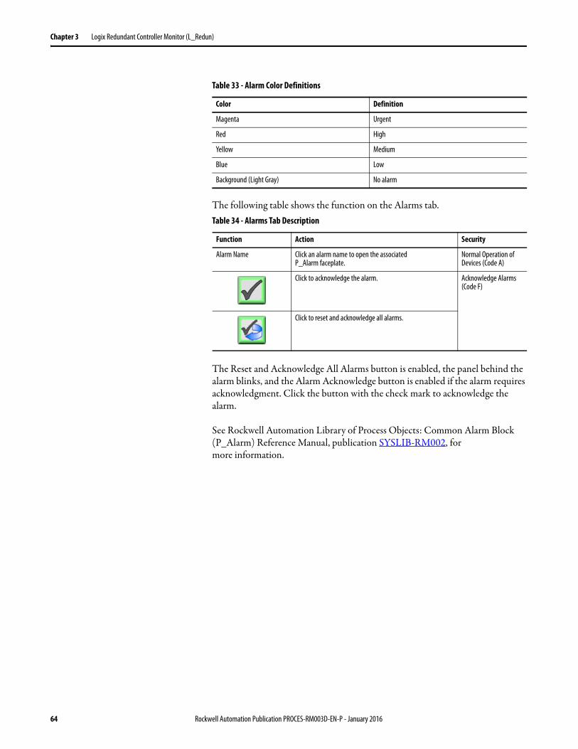
Chapter 3 Logix Redundant Controller Monitor (L_Redun)
The following table shows the function on the Alarms tab.
The Reset and Acknowledge All Alarms button is enabled, the panel behind the alarm blinks, and the Alarm Acknowledge button is enabled if the alarm requires acknowledgment. Click the button with the check mark to acknowledge the alarm.
See Rockwell Automation Library of Process Objects: Common Alarm Block (P_Alarm) Reference Manual, publication SYSLIB-RM002, for more information.
Table 33 - Alarm Color Definitions
Color Definition
Magenta Urgent
Red High
Yellow Medium
Blue Low
Background (Light Gray) No alarm
Table 34 - Alarms Tab Description
Function Action Security
Alarm Name Click an alarm name to open the associatedP_Alarm faceplate.
Normal Operation of Devices (Code A)
Click to acknowledge the alarm. Acknowledge Alarms (Code F)
Click to reset and acknowledge all alarms.
64 Rockwell Automation Publication PROCES-RM003D-EN-P - January 2016
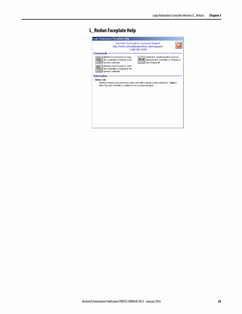
Logix Redundant Controller Monitor (L_Redun) Chapter 3
L_Redun Faceplate Help
Rockwell Automation Publication PROCES-RM003D-EN-P - January 2016 65

Chapter 3 Logix Redundant Controller Monitor (L_Redun)
Notes:
66 Rockwell Automation Publication PROCES-RM003D-EN-P - January 2016
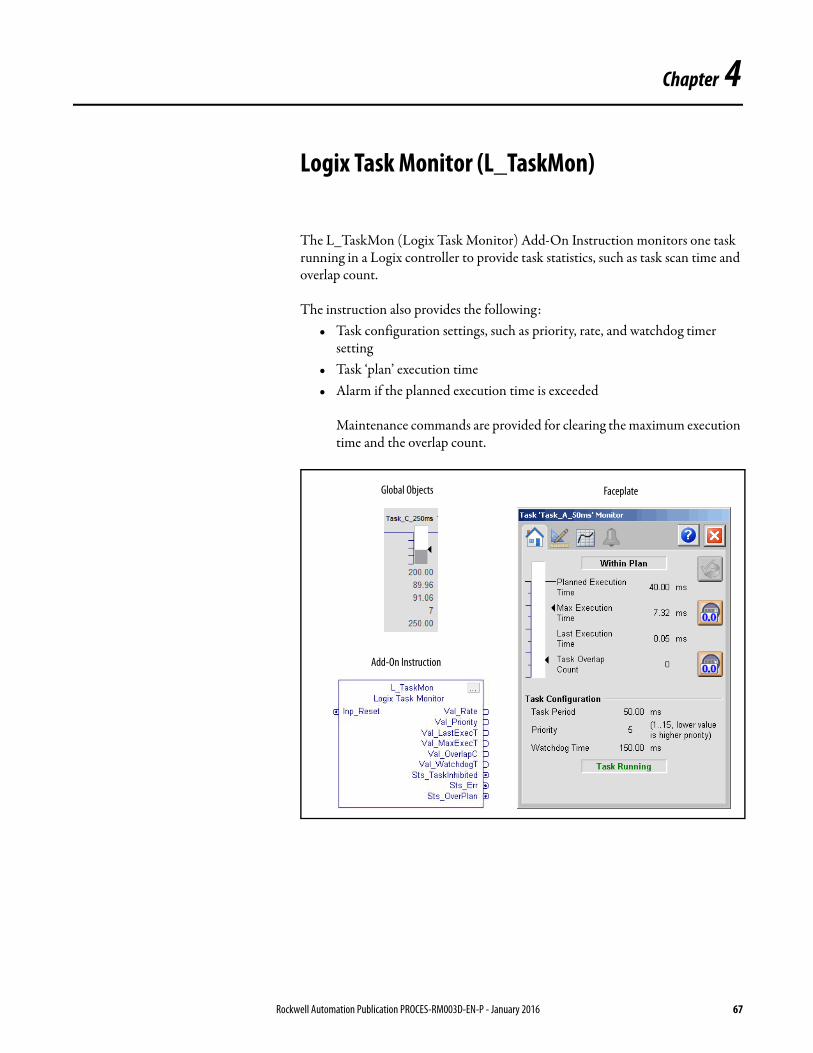
Chapter 4
Logix Task Monitor (L_TaskMon)
The L_TaskMon (Logix Task Monitor) Add-On Instruction monitors one task running in a Logix controller to provide task statistics, such as task scan time and overlap count.
The instruction also provides the following:• Task configuration settings, such as priority, rate, and watchdog timer
setting• Task ‘plan’ execution time• Alarm if the planned execution time is exceeded
Maintenance commands are provided for clearing the maximum execution time and the overlap count.
Add-On Instruction
Global Objects Faceplate
Rockwell Automation Publication PROCES-RM003D-EN-P - January 2016 67
Chapter 4 Logix Task Monitor (L_TaskMon)
Guidelines Use this instruction in these situations:• Monitor the execution of one or more tasks in a Logix controller• Set an alarm when task execution time exceeds a ‘plan’ threshold
Do not use this instruction if you are using suitable software or another method to monitor controller task execution.
Functional Description The L_TaskMon instruction includes an Add-On Instruction for use with:• RSLogix 5000 software, version 18 or later• Logix controllers, firmware revision 18 or later• graphic symbol and faceplate display for use with either FactoryTalk View
Site Edition or Machine Edition software, version 7.0 or later.
Required Files Add-On Instructions are reusable code objects that contain encapsulated logic that can streamline implementing your system. This code lets you create your own instruction set for programming logic as a supplement to the instruction set provided natively in the ControlLogix firmware. An Add-On Instruction is defined once in each controller project, and can be instantiated multiple times in your application code as needed.
Controller File
The L_TaskMon_3_5-00_RUNG.L5X Add-On Instruction must be imported into the controller project for use in the controller configuration. The service release number (boldfaced) can change as service revisions are created.
The import file is available from the Product Compatibility and Download Center at http://www.rockwellautomation.com/rockwellautomation/support/pcdc.page.
Visualization Files
The Process Library contains visualization files for built-in firmware instructions which provide a common user interface. These files can be downloaded from the Product Compatibility and Download Center at http://www.rockwellautomation.com/global/support/pcdc.page.
This Add-On Instruction has associated visualization files that provide a common user interface. These files can be downloaded from the Product Compatibility and Download Center at http://www.rockwellautomation.com/rockwellautomation/support/pcdc.page.
68 Rockwell Automation Publication PROCES-RM003D-EN-P - January 2016
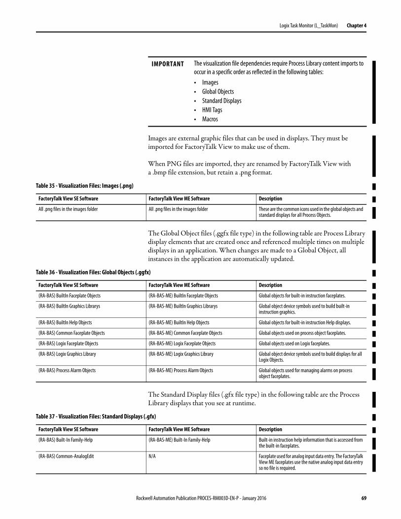
Logix Task Monitor (L_TaskMon) Chapter 4
Images are external graphic files that can be used in displays. They must be imported for FactoryTalk View to make use of them.
When PNG files are imported, they are renamed by FactoryTalk View with a .bmp file extension, but retain a .png format.
The Global Object files (.ggfx file type) in the following table are Process Library display elements that are created once and referenced multiple times on multiple displays in an application. When changes are made to a Global Object, all instances in the application are automatically updated.
The Standard Display files (.gfx file type) in the following table are the Process Library displays that you see at runtime.
IMPORTANT The visualization file dependencies require Process Library content imports to occur in a specific order as reflected in the following tables:• Images• Global Objects• Standard Displays• HMI Tags• Macros
Table 35 - Visualization Files: Images (.png)
FactoryTalk View SE Software FactoryTalk View ME Software Description
All .png files in the images folder All .png files in the images folder These are the common icons used in the global objects and standard displays for all Process Objects.
Table 36 - Visualization Files: Global Objects (.ggfx)
FactoryTalk View SE Software FactoryTalk View ME Software Description
(RA-BAS) BuiltIn Faceplate Objects (RA-BAS-ME) BuiltIn Faceplate Objects Global objects for built-in instruction faceplates.
(RA-BAS) BuiltIn Graphics Librarys (RA-BAS-ME) BuiltIn Graphics Librarys Global object device symbols used to build built-in instruction graphics.
(RA-BAS) BuiltIn Help Objects (RA-BAS-ME) BuiltIn Help Objects Global objects for built-in instruction Help displays.
(RA-BAS) Common Faceplate Objects (RA-BAS-ME) Common Faceplate Objects Global objects used on process object faceplates.
(RA-BAS) Logix Faceplate Objects (RA-BAS-ME) Logix Faceplate Objects Global objects used on Logix faceplates.
(RA-BAS) Logix Graphics Library (RA-BAS-ME) Logix Graphics Library Global object device symbols used to build displays for all Logix Objects.
(RA-BAS) Process Alarm Objects (RA-BAS-ME) Process Alarm Objects Global objects used for managing alarms on process object faceplates.
Table 37 - Visualization Files: Standard Displays (.gfx)
FactoryTalk View SE Software FactoryTalk View ME Software Description
(RA-BAS) Built-In Family-Help (RA-BAS-ME) Built-In Family-Help Built-in instruction help information that is accessed from the built-in faceplates.
(RA-BAS) Common-AnalogEdit N/A Faceplate used for analog input data entry. The FactoryTalk View ME faceplates use the native analog input data entry so no file is required.
Rockwell Automation Publication PROCES-RM003D-EN-P - January 2016 69
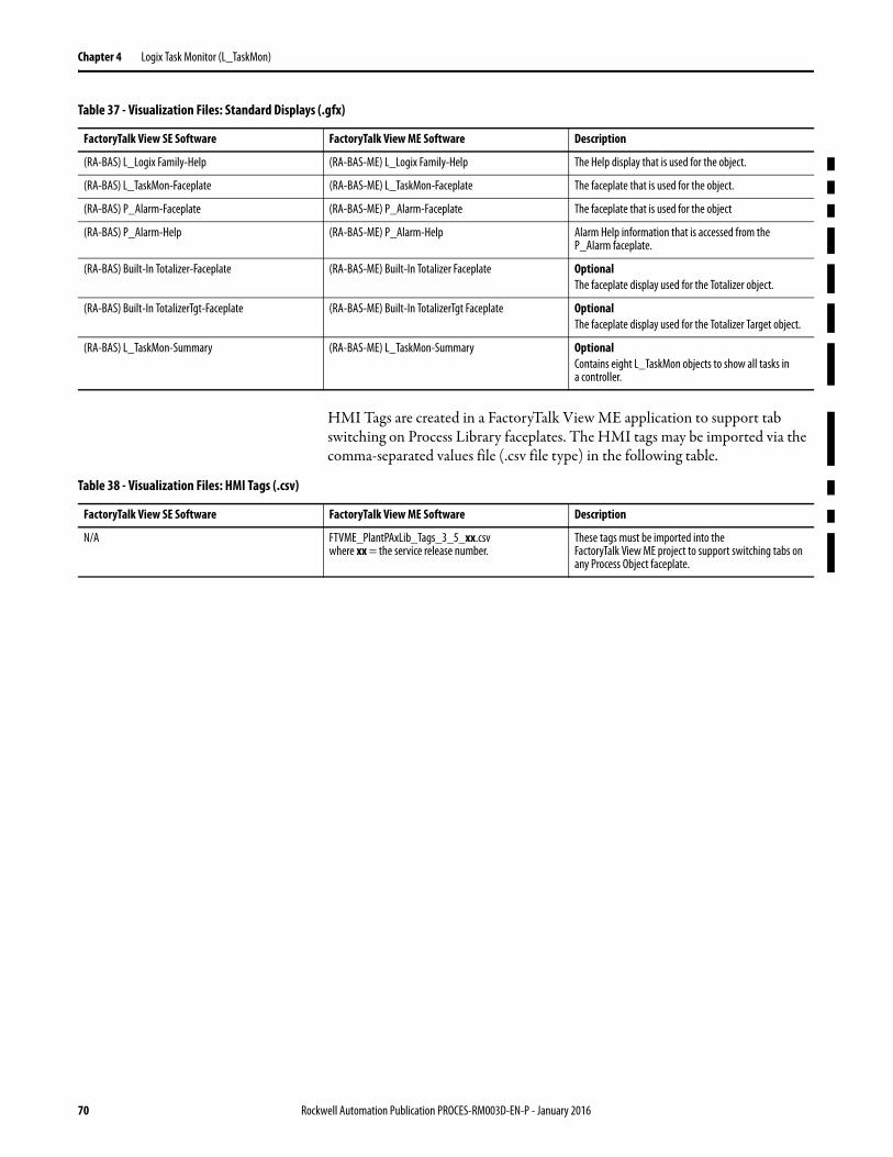
Chapter 4 Logix Task Monitor (L_TaskMon)
HMI Tags are created in a FactoryTalk View ME application to support tab switching on Process Library faceplates. The HMI tags may be imported via the comma-separated values file (.csv file type) in the following table.
(RA-BAS) L_Logix Family-Help (RA-BAS-ME) L_Logix Family-Help The Help display that is used for the object.
(RA-BAS) L_TaskMon-Faceplate (RA-BAS-ME) L_TaskMon-Faceplate The faceplate that is used for the object.
(RA-BAS) P_Alarm-Faceplate (RA-BAS-ME) P_Alarm-Faceplate The faceplate that is used for the object
(RA-BAS) P_Alarm-Help (RA-BAS-ME) P_Alarm-Help Alarm Help information that is accessed from the P_AIarm faceplate.
(RA-BAS) Built-In Totalizer-Faceplate (RA-BAS-ME) Built-In Totalizer Faceplate OptionalThe faceplate display used for the Totalizer object.
(RA-BAS) Built-In TotalizerTgt-Faceplate (RA-BAS-ME) Built-In TotalizerTgt Faceplate OptionalThe faceplate display used for the Totalizer Target object.
(RA-BAS) L_TaskMon-Summary (RA-BAS-ME) L_TaskMon-Summary OptionalContains eight L_TaskMon objects to show all tasks in a controller.
Table 37 - Visualization Files: Standard Displays (.gfx)
FactoryTalk View SE Software FactoryTalk View ME Software Description
Table 38 - Visualization Files: HMI Tags (.csv)
FactoryTalk View SE Software FactoryTalk View ME Software Description
N/A FTVME_PlantPAxLib_Tags_3_5_xx.csvwhere xx = the service release number.
These tags must be imported into theFactoryTalk View ME project to support switching tabs on any Process Object faceplate.
70 Rockwell Automation Publication PROCES-RM003D-EN-P - January 2016
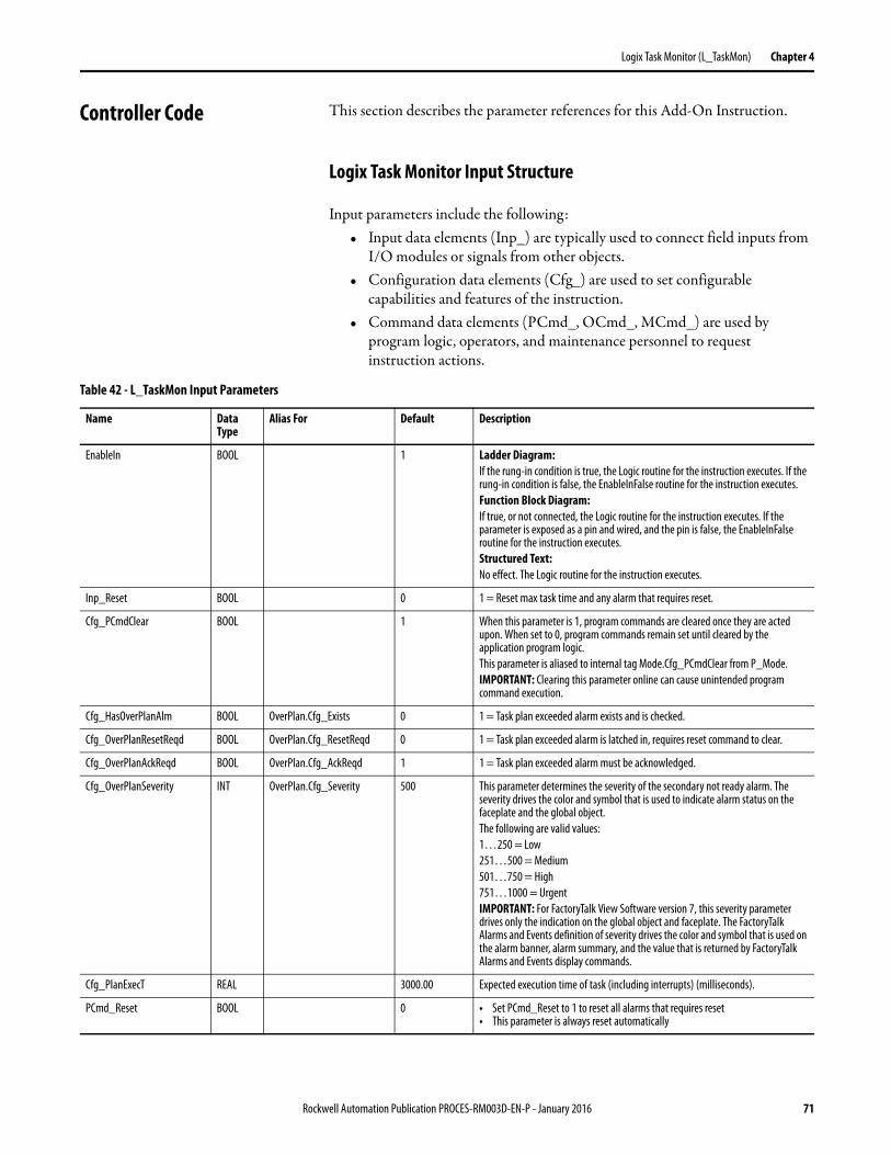
Logix Task Monitor (L_TaskMon) Chapter 4
Controller Code This section describes the parameter references for this Add-On Instruction.
Logix Task Monitor Input Structure
Input parameters include the following:• Input data elements (Inp_) are typically used to connect field inputs from
I/O modules or signals from other objects.• Configuration data elements (Cfg_) are used to set configurable
capabilities and features of the instruction.• Command data elements (PCmd_, OCmd_, MCmd_) are used by
program logic, operators, and maintenance personnel to request instruction actions.
Table 42 - L_TaskMon Input Parameters
Name Data Type
Alias For Default Description
EnableIn BOOL 1 Ladder Diagram:If the rung-in condition is true, the Logic routine for the instruction executes. If the rung-in condition is false, the EnableInFalse routine for the instruction executes.Function Block Diagram:If true, or not connected, the Logic routine for the instruction executes. If the parameter is exposed as a pin and wired, and the pin is false, the EnableInFalse routine for the instruction executes.Structured Text:No effect. The Logic routine for the instruction executes.
Inp_Reset BOOL 0 1 = Reset max task time and any alarm that requires reset.
Cfg_PCmdClear BOOL 1 When this parameter is 1, program commands are cleared once they are acted upon. When set to 0, program commands remain set until cleared by the application program logic.This parameter is aliased to internal tag Mode.Cfg_PCmdClear from P_Mode.IMPORTANT: Clearing this parameter online can cause unintended program command execution.
Cfg_HasOverPlanAlm BOOL OverPlan.Cfg_Exists 0 1 = Task plan exceeded alarm exists and is checked.
Cfg_OverPlanResetReqd BOOL OverPlan.Cfg_ResetReqd 0 1 = Task plan exceeded alarm is latched in, requires reset command to clear.
Cfg_OverPlanAckReqd BOOL OverPlan.Cfg_AckReqd 1 1 = Task plan exceeded alarm must be acknowledged.
Cfg_OverPlanSeverity INT OverPlan.Cfg_Severity 500 This parameter determines the severity of the secondary not ready alarm. The severity drives the color and symbol that is used to indicate alarm status on the faceplate and the global object. The following are valid values:1…250 = Low251…500 = Medium501…750 = High751…1000 = UrgentIMPORTANT: For FactoryTalk View Software version 7, this severity parameter drives only the indication on the global object and faceplate. The FactoryTalk Alarms and Events definition of severity drives the color and symbol that is used on the alarm banner, alarm summary, and the value that is returned by FactoryTalk Alarms and Events display commands.
Cfg_PlanExecT REAL 3000.00 Expected execution time of task (including interrupts) (milliseconds).
PCmd_Reset BOOL 0 • Set PCmd_Reset to 1 to reset all alarms that requires reset• This parameter is always reset automatically
Rockwell Automation Publication PROCES-RM003D-EN-P - January 2016 71
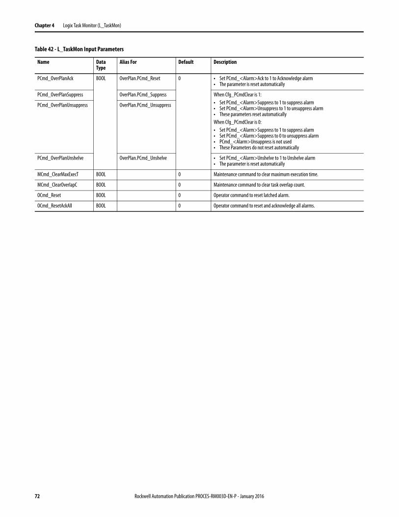
Chapter 4 Logix Task Monitor (L_TaskMon)
PCmd_OverPlanAck BOOL OverPlan.PCmd_Reset 0 • Set PCmd_<Alarm>Ack to 1 to Acknowledge alarm• The parameter is reset automatically
PCmd_OverPlanSuppress OverPlan.PCmd_Suppress When Cfg_PCmdClear is 1:• Set PCmd_<Alarm>Suppress to 1 to suppress alarm• Set PCmd_<Alarm>Unsuppress to 1 to unsuppress alarm• These parameters reset automaticallyWhen Cfg_PCmdClear is 0:• Set PCmd_<Alarm>Suppress to 1 to suppress alarm• Set PCmd_<Alarm>Suppress to 0 to unsuppress alarm• PCmd_<Alarm>Unsuppress is not used • These Parameters do not reset automatically
PCmd_OverPlanUnsuppress OverPlan.PCmd_Unsuppress
PCmd_OverPlanUnshelve OverPlan.PCmd_Unshelve • Set PCmd_<Alarm>Unshelve to 1 to Unshelve alarm• The parameter is reset automatically
MCmd_ClearMaxExecT BOOL 0 Maintenance command to clear maximum execution time.
MCmd_ClearOverlapC BOOL 0 Maintenance command to clear task overlap count.
OCmd_Reset BOOL 0 Operator command to reset latched alarm.
OCmd_ResetAckAll BOOL 0 Operator command to reset and acknowledge all alarms.
Table 42 - L_TaskMon Input Parameters
Name Data Type
Alias For Default Description
72 Rockwell Automation Publication PROCES-RM003D-EN-P - January 2016
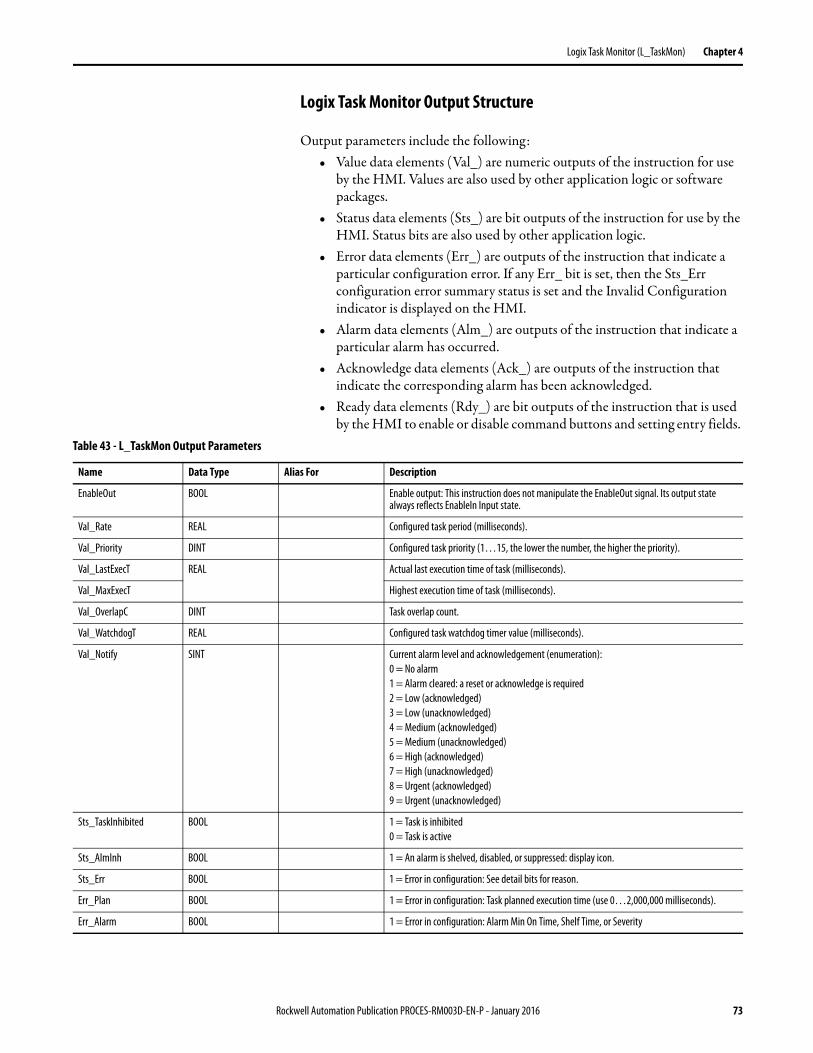
Logix Task Monitor (L_TaskMon) Chapter 4
Logix Task Monitor Output Structure
Output parameters include the following:• Value data elements (Val_) are numeric outputs of the instruction for use
by the HMI. Values are also used by other application logic or software packages.
• Status data elements (Sts_) are bit outputs of the instruction for use by the HMI. Status bits are also used by other application logic.
• Error data elements (Err_) are outputs of the instruction that indicate a particular configuration error. If any Err_ bit is set, then the Sts_Err configuration error summary status is set and the Invalid Configuration indicator is displayed on the HMI.
• Alarm data elements (Alm_) are outputs of the instruction that indicate a particular alarm has occurred.
• Acknowledge data elements (Ack_) are outputs of the instruction that indicate the corresponding alarm has been acknowledged.
• Ready data elements (Rdy_) are bit outputs of the instruction that is used by the HMI to enable or disable command buttons and setting entry fields.
Table 43 - L_TaskMon Output Parameters
Name Data Type Alias For Description
EnableOut BOOL Enable output: This instruction does not manipulate the EnableOut signal. Its output state always reflects EnableIn Input state.
Val_Rate REAL Configured task period (milliseconds).
Val_Priority DINT Configured task priority (1…15, the lower the number, the higher the priority).
Val_LastExecT REAL Actual last execution time of task (milliseconds).
Val_MaxExecT Highest execution time of task (milliseconds).
Val_OverlapC DINT Task overlap count.
Val_WatchdogT REAL Configured task watchdog timer value (milliseconds).
Val_Notify SINT Current alarm level and acknowledgement (enumeration):0 = No alarm1 = Alarm cleared: a reset or acknowledge is required2 = Low (acknowledged)3 = Low (unacknowledged)4 = Medium (acknowledged)5 = Medium (unacknowledged)6 = High (acknowledged)7 = High (unacknowledged)8 = Urgent (acknowledged)9 = Urgent (unacknowledged)
Sts_TaskInhibited BOOL 1 = Task is inhibited0 = Task is active
Sts_AlmInh BOOL 1 = An alarm is shelved, disabled, or suppressed: display icon.
Sts_Err BOOL 1 = Error in configuration: See detail bits for reason.
Err_Plan BOOL 1 = Error in configuration: Task planned execution time (use 0…2,000,000 milliseconds).
Err_Alarm BOOL 1 = Error in configuration: Alarm Min On Time, Shelf Time, or Severity
Rockwell Automation Publication PROCES-RM003D-EN-P - January 2016 73
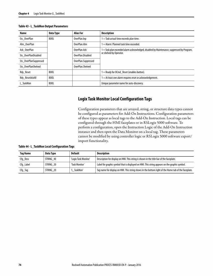
Chapter 4 Logix Task Monitor (L_TaskMon)
Logix Task Monitor Local Configuration Tags
Configuration parameters that are arrayed, string, or structure data types cannot be configured as parameters for Add-On Instructions. Configuration parameters of these types appear as local tags to the Add-On Instruction. Local tags can be configured through the HMI faceplates or in RSLogix 5000 software. To perform a configuration, open the Instruction Logic of the Add-On Instruction instance and then open the Data Monitor on a local tag. These parameters cannot be modified by using controller logic or RSLogix 5000 software export/import functionality.
Sts_OverPlan BOOL OverPlan.Inp 1 = Task actual time exceeds plan time.
Alm_OverPlan OverPlan.Alm 1 = Alarm: Planned task time exceeded.
Ack_OverPlan OverPlan.Ack 1 = Task plan exceeded alarm acknowledged, disabled by Maintenance, suppressed by Program, or shelved by Operator.
Sts_OverPlanDisabled OverPlan.Disabled
Sts_OverPlanSuppressed OverPlan.Suppressed
Sts_OverPlanShelved OverPlan.Shelved
Rdy_Reset BOOL 1 = Ready for OCmd_Reset (enables button).
Rdy_ResetAckAll BOOL 1 = At least one alarm requires reset or acknowledgement.
L_TaskMon BOOL Unique parameter name for auto-discovery.
Table 43 - L_TaskMon Output Parameters
Name Data Type Alias For Description
Table 44 - L_TaskMon Local Configuration Tags
Tag Name Data Type Default Description
Cfg_Desc STRING_40 'Logix Task Monitor' Description for display on HMI. This string is shown in the title bar of the faceplate.
Cfg_Label STRING_20 'Task Monitor' Label for graphic symbol that is displayed on HMI. This string appears on the graphic symbol.
Cfg_Tag STRING_20 'L_TaskMon' Tag name for display on HMI. This string shows in the bottom right of the Home tab of the faceplate.
74 Rockwell Automation Publication PROCES-RM003D-EN-P - January 2016
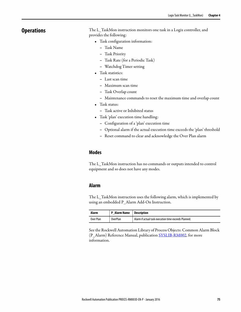
Logix Task Monitor (L_TaskMon) Chapter 4
Operations The L_TaskMon instruction monitors one task in a Logix controller, and provides the following:
• Task configuration information:– Task Name– Task Priority– Task Rate (for a Periodic Task)– Watchdog Timer setting
• Task statistics:– Last scan time– Maximum scan time– Task Overlap count– Maintenance commands to reset the maximum time and overlap count
• Task status:– Task active or Inhibited status
• Task ‘plan’ execution time handling:– Configuration of a ‘plan’ execution time– Optional alarm if the actual execution time exceeds the ‘plan’ threshold– Reset command to clear and acknowledge the Over Plan alarm
Modes
The L_TaskMon instruction has no commands or outputs intended to control equipment and so does not have any modes.
Alarm
The L_TaskMon instruction uses the following alarm, which is implemented by using an embedded P_Alarm Add-On Instruction.
See the Rockwell Automation Library of Process Objects: Common Alarm Block (P_Alarm) Reference Manual, publication SYSLIB-RM002, for more information.
Alarm P_Alarm Name Description
Over Plan OverPlan Alarm if actual task execution time exceeds Planned.
Rockwell Automation Publication PROCES-RM003D-EN-P - January 2016 75
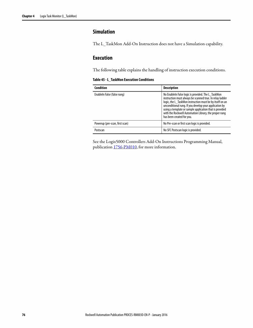
Chapter 4 Logix Task Monitor (L_TaskMon)
Simulation
The L_TaskMon Add-On Instruction does not have a Simulation capability.
Execution
The following table explains the handling of instruction execution conditions.
See the Logix5000 Controllers Add-On Instructions Programming Manual, publication 1756-PM010, for more information.
Table 45 - L_TaskMon Execution Conditions
Condition Description
EnableIn False (false rung) No EnableIn False logic is provided. The L_TaskMon instruction must always be scanned true. In relay ladder logic, the L_TaskMon instruction must be by itself on an unconditional rung. If you develop your application by using a template or sample application that is provided with the Rockwell Automation Library, the proper rung has been created for you.
Powerup (pre-scan, first scan) No Pre-scan or first scan logic is provided.
Postscan No SFC Postscan logic is provided.
76 Rockwell Automation Publication PROCES-RM003D-EN-P - January 2016
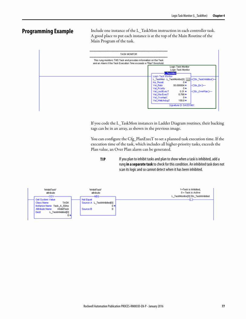
Logix Task Monitor (L_TaskMon) Chapter 4
Programming Example Include one instance of the L_TaskMon instruction in each controller task. A good place to put each instance is at the top of the Main Routine of theMain Program of the task.
If you code the L_TaskMon instances in Ladder Diagram routines, their backing tags can be in an array, as shown in the previous image.
You can configure the Cfg_PlanExecT to set a planned task execution time. If the execution time of the task, which includes all higher-priority tasks, exceeds the Plan value, an Over Plan alarm can be generated.
TIP If you plan to inhibit tasks and plan to show when a task is inhibited, add a rung in a separate task to check for this condition. An inhibited task does not scan its logic and so cannot detect when it has been inhibited.
Rockwell Automation Publication PROCES-RM003D-EN-P - January 2016 77
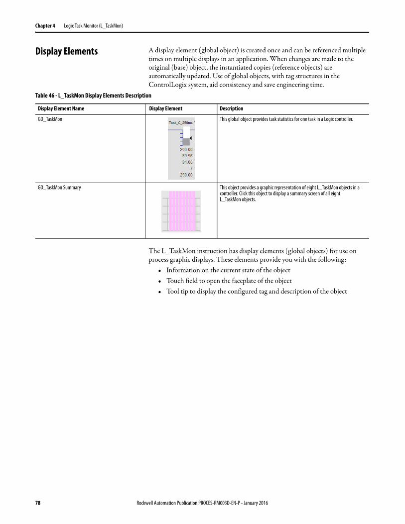
Chapter 4 Logix Task Monitor (L_TaskMon)
Display Elements A display element (global object) is created once and can be referenced multiple times on multiple displays in an application. When changes are made to the original (base) object, the instantiated copies (reference objects) are automatically updated. Use of global objects, with tag structures in the ControlLogix system, aid consistency and save engineering time.
The L_TaskMon instruction has display elements (global objects) for use on process graphic displays. These elements provide you with the following:
• Information on the current state of the object• Touch field to open the faceplate of the object• Tool tip to display the configured tag and description of the object
Table 46 - L_TaskMon Display Elements Description
Display Element Name Display Element Description
GO_TaskMon This global object provides task statistics for one task in a Logix controller.
GO_TaskMon Summary This object provides a graphic representation of eight L_TaskMon objects in a controller. Click this object to display a summary screen of all eight L_TaskMon objects.
78 Rockwell Automation Publication PROCES-RM003D-EN-P - January 2016
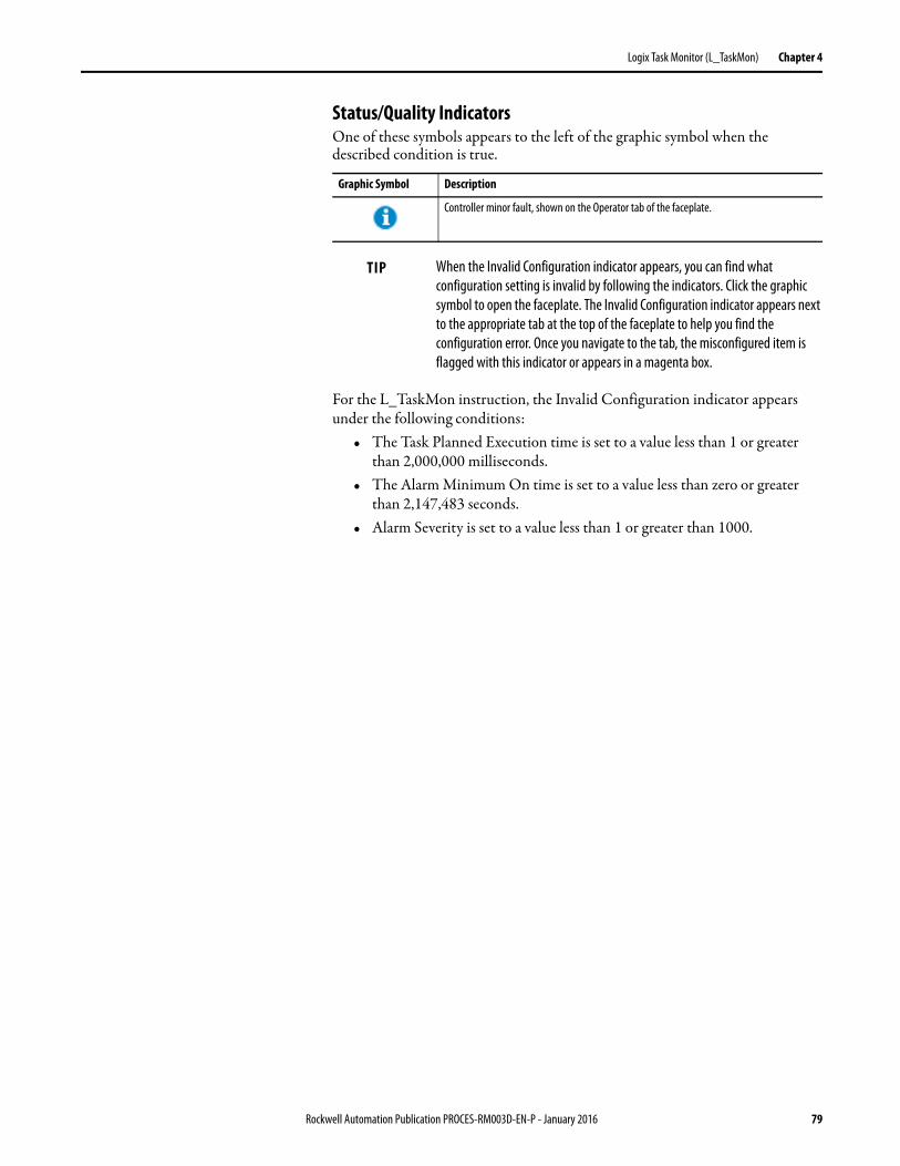
Logix Task Monitor (L_TaskMon) Chapter 4
Status/Quality IndicatorsOne of these symbols appears to the left of the graphic symbol when the described condition is true.
For the L_TaskMon instruction, the Invalid Configuration indicator appears under the following conditions:
• The Task Planned Execution time is set to a value less than 1 or greater than 2,000,000 milliseconds.
• The Alarm Minimum On time is set to a value less than zero or greater than 2,147,483 seconds.
• Alarm Severity is set to a value less than 1 or greater than 1000.
Graphic Symbol Description
Controller minor fault, shown on the Operator tab of the faceplate.
TIP When the Invalid Configuration indicator appears, you can find what configuration setting is invalid by following the indicators. Click the graphic symbol to open the faceplate. The Invalid Configuration indicator appears next to the appropriate tab at the top of the faceplate to help you find the configuration error. Once you navigate to the tab, the misconfigured item is flagged with this indicator or appears in a magenta box.
Rockwell Automation Publication PROCES-RM003D-EN-P - January 2016 79
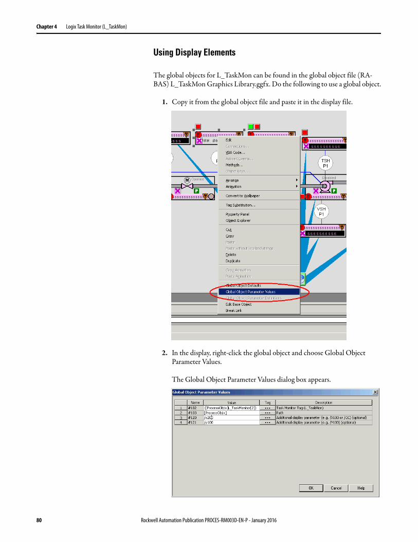
Chapter 4 Logix Task Monitor (L_TaskMon)
Using Display Elements
The global objects for L_TaskMon can be found in the global object file (RA-BAS) L_TaskMon Graphics Library.ggfx. Do the following to use a global object.
1. Copy it from the global object file and paste it in the display file.
2. In the display, right-click the global object and choose Global Object Parameter Values.
The Global Object Parameter Values dialog box appears.
80 Rockwell Automation Publication PROCES-RM003D-EN-P - January 2016
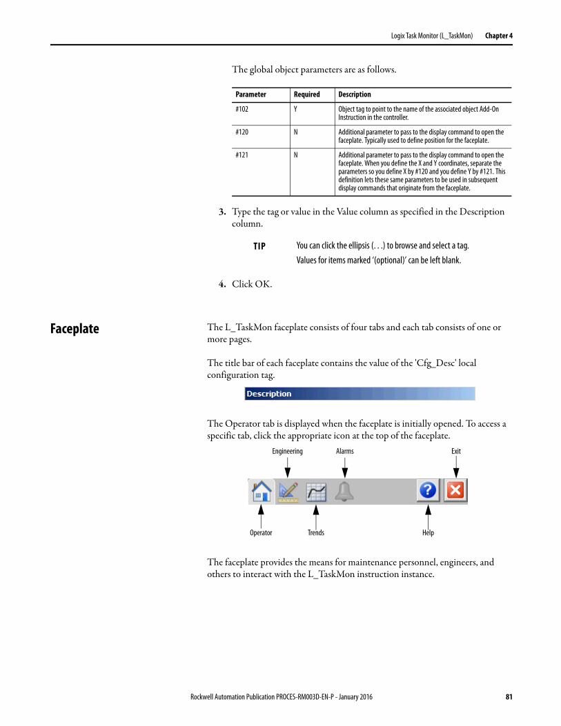
Logix Task Monitor (L_TaskMon) Chapter 4
The global object parameters are as follows.
3. Type the tag or value in the Value column as specified in the Description column.
4. Click OK.
Faceplate The L_TaskMon faceplate consists of four tabs and each tab consists of one or more pages.
The title bar of each faceplate contains the value of the 'Cfg_Desc' local configuration tag.
The Operator tab is displayed when the faceplate is initially opened. To access a specific tab, click the appropriate icon at the top of the faceplate.
The faceplate provides the means for maintenance personnel, engineers, and others to interact with the L_TaskMon instruction instance.
Parameter Required Description
#102 Y Object tag to point to the name of the associated object Add-On Instruction in the controller.
#120 N Additional parameter to pass to the display command to open the faceplate. Typically used to define position for the faceplate.
#121 N Additional parameter to pass to the display command to open the faceplate. When you define the X and Y coordinates, separate the parameters so you define X by #120 and you define Y by #121. This definition lets these same parameters to be used in subsequent display commands that originate from the faceplate.
TIP You can click the ellipsis (. . .) to browse and select a tag. Values for items marked ‘(optional)’ can be left blank.
Operator
Engineering
Trends
Alarms Exit
Help
Rockwell Automation Publication PROCES-RM003D-EN-P - January 2016 81
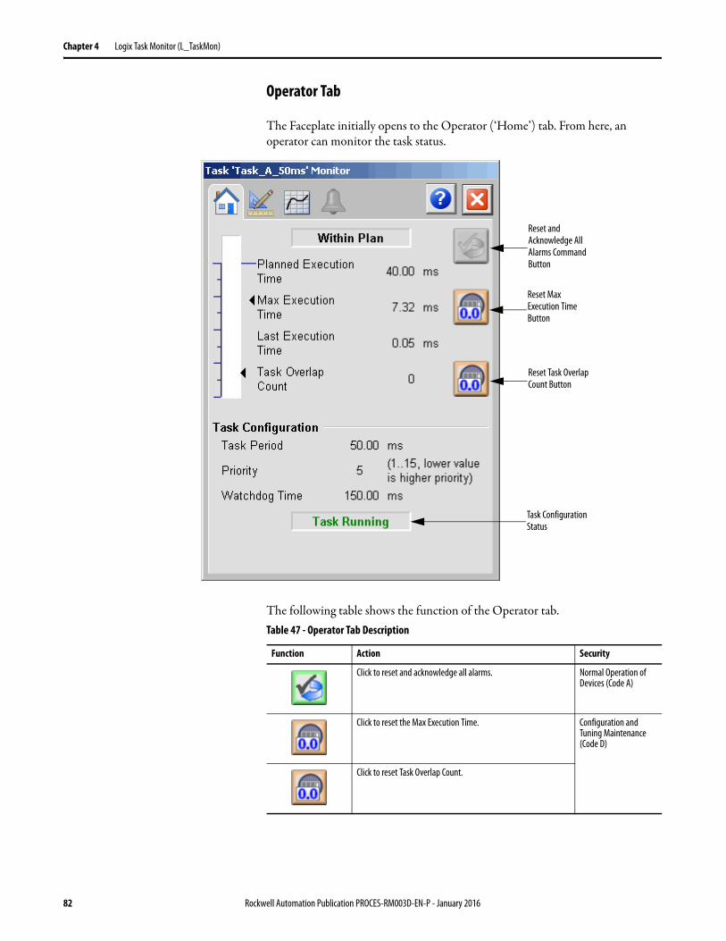
Chapter 4 Logix Task Monitor (L_TaskMon)
Operator Tab
The Faceplate initially opens to the Operator (‘Home’) tab. From here, an operator can monitor the task status.
The following table shows the function of the Operator tab.
Reset and Acknowledge All Alarms Command Button
Reset Max Execution Time Button
Reset Task Overlap Count Button
Task Configuration Status
Table 47 - Operator Tab Description
Function Action Security
Click to reset and acknowledge all alarms. Normal Operation of Devices (Code A)
Click to reset the Max Execution Time. Configuration and Tuning Maintenance (Code D)
Click to reset Task Overlap Count.
82 Rockwell Automation Publication PROCES-RM003D-EN-P - January 2016
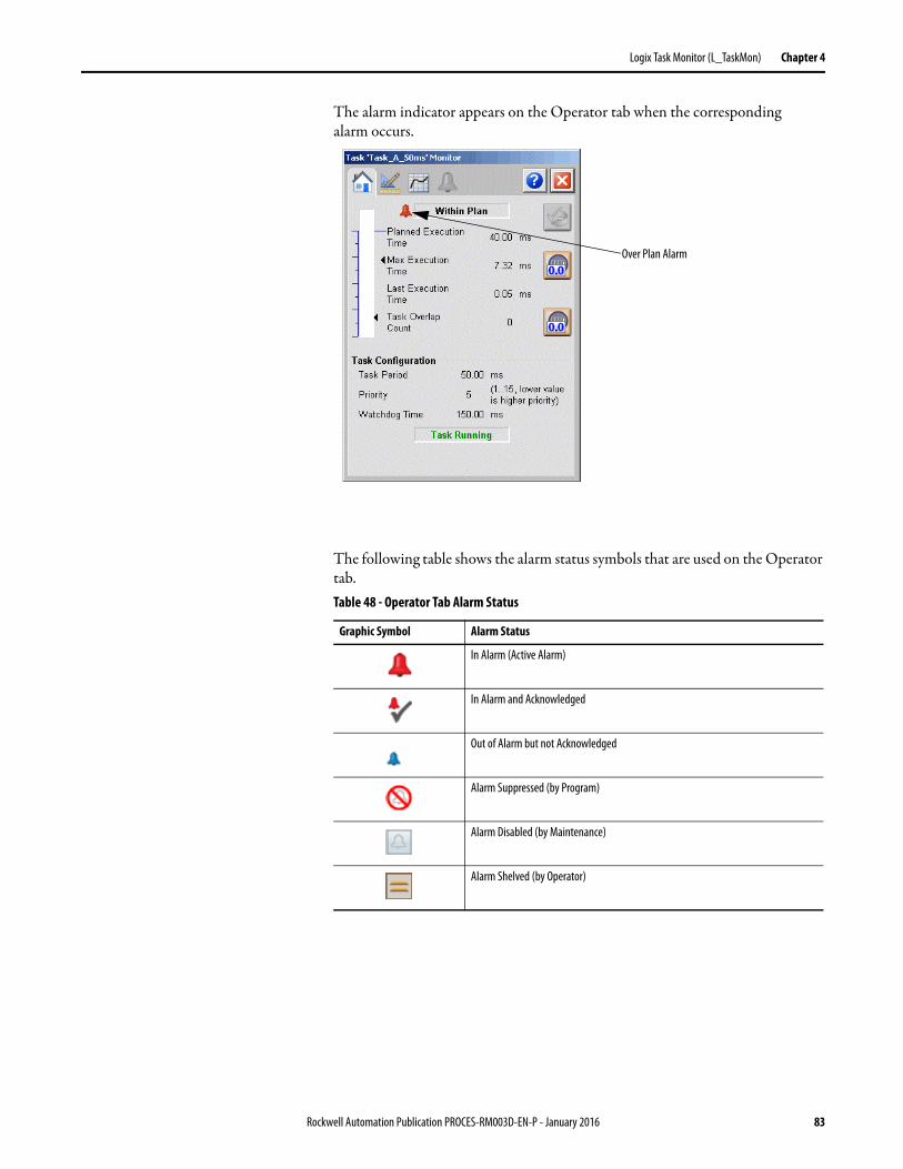
Logix Task Monitor (L_TaskMon) Chapter 4
The alarm indicator appears on the Operator tab when the corresponding alarm occurs.
The following table shows the alarm status symbols that are used on the Operator tab.Table 48 - Operator Tab Alarm Status
Graphic Symbol Alarm Status
In Alarm (Active Alarm)
In Alarm and Acknowledged
Out of Alarm but not Acknowledged
Alarm Suppressed (by Program)
Alarm Disabled (by Maintenance)
Alarm Shelved (by Operator)
Over Plan Alarm
Rockwell Automation Publication PROCES-RM003D-EN-P - January 2016 83
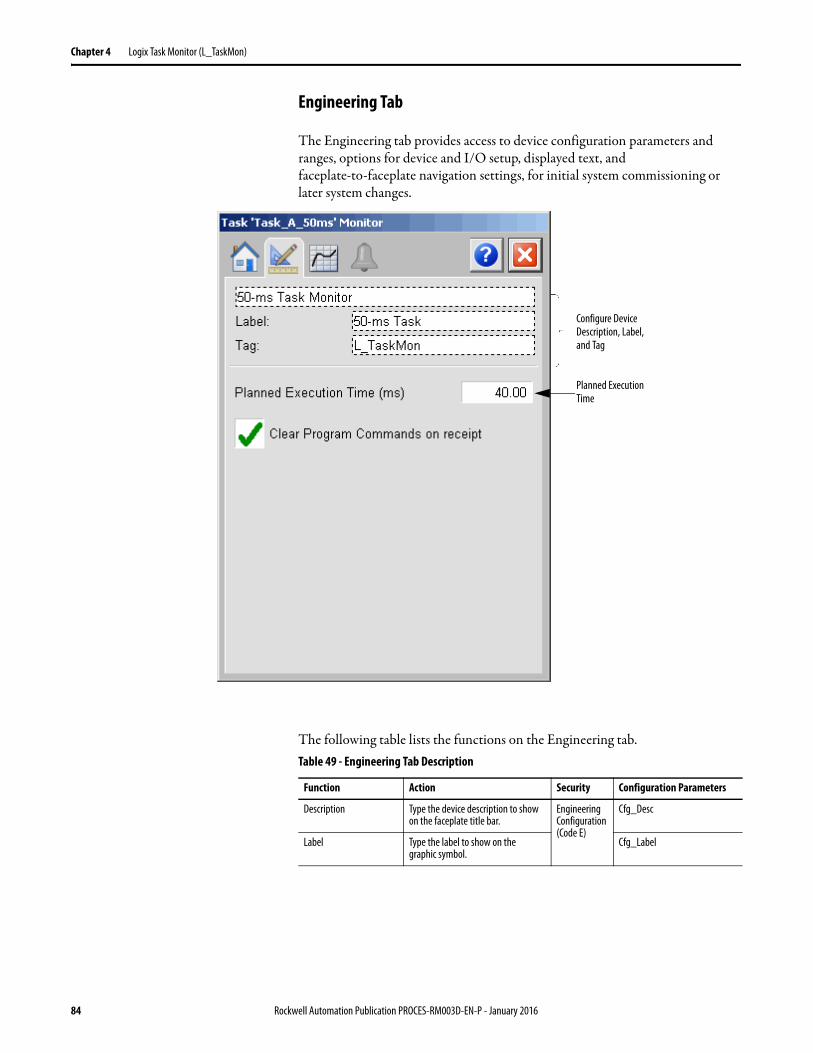
Chapter 4 Logix Task Monitor (L_TaskMon)
Engineering Tab
The Engineering tab provides access to device configuration parameters and ranges, options for device and I/O setup, displayed text, and faceplate-to-faceplate navigation settings, for initial system commissioning or later system changes.
The following table lists the functions on the Engineering tab.
Planned Execution Time
Configure Device Description, Label, and Tag
Table 49 - Engineering Tab Description
Function Action Security Configuration Parameters
Description Type the device description to show on the faceplate title bar.
Engineering Configuration (Code E)
Cfg_Desc
Label Type the label to show on the graphic symbol.
Cfg_Label
84 Rockwell Automation Publication PROCES-RM003D-EN-P - January 2016
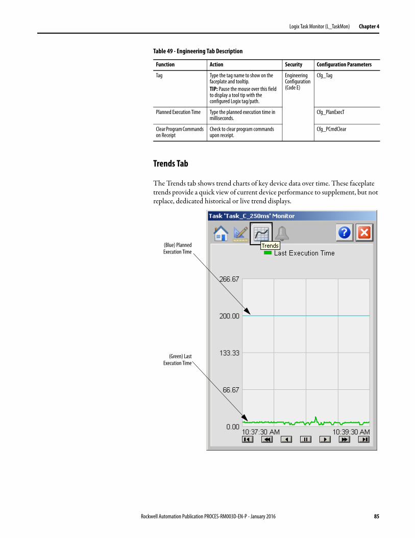
Logix Task Monitor (L_TaskMon) Chapter 4
Trends Tab
The Trends tab shows trend charts of key device data over time. These faceplate trends provide a quick view of current device performance to supplement, but not replace, dedicated historical or live trend displays.
Tag Type the tag name to show on the faceplate and tooltip.TIP: Pause the mouse over this field to display a tool tip with the configured Logix tag/path.
Engineering Configuration (Code E)
Cfg_Tag
Planned Execution Time Type the planned execution time in milliseconds.
Cfg_PlanExecT
Clear Program Commands on Receipt
Check to clear program commands upon receipt.
Cfg_PCmdClear
Table 49 - Engineering Tab Description
Function Action Security Configuration Parameters
(Green) LastExecution Time
(Blue) PlannedExecution Time
Rockwell Automation Publication PROCES-RM003D-EN-P - January 2016 85
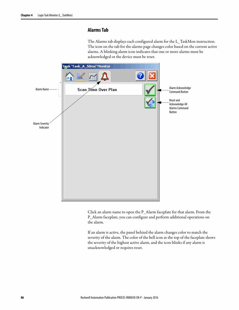
Chapter 4 Logix Task Monitor (L_TaskMon)
Alarms Tab
The Alarms tab displays each configured alarm for the L_TaskMon instruction. The icon on the tab for the alarms page changes color based on the current active alarms. A blinking alarm icon indicates that one or more alarms must be acknowledged or the device must be reset.
Click an alarm name to open the P_Alarm faceplate for that alarm. From the P_Alarm faceplate, you can configure and perform additional operations on the alarm.
If an alarm is active, the panel behind the alarm changes color to match the severity of the alarm. The color of the bell icon at the top of the faceplate shows the severity of the highest active alarm, and the icon blinks if any alarm is unacknowledged or requires reset.
Alarm Name Alarm Acknowledge Command Button
Reset and Acknowledge All Alarms Command Button
Alarm SeverityIndicator
86 Rockwell Automation Publication PROCES-RM003D-EN-P - January 2016
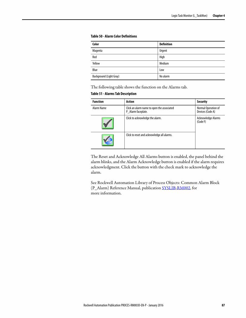
Logix Task Monitor (L_TaskMon) Chapter 4
The following table shows the function on the Alarms tab.
The Reset and Acknowledge All Alarms button is enabled, the panel behind the alarm blinks, and the Alarm Acknowledge button is enabled if the alarm requires acknowledgment. Click the button with the check mark to acknowledge the alarm.
See Rockwell Automation Library of Process Objects: Common Alarm Block (P_Alarm) Reference Manual, publication SYSLIB-RM002, for more information.
Table 50 - Alarm Color Definitions
Color Definition
Magenta Urgent
Red High
Yellow Medium
Blue Low
Background (Light Gray) No alarm
Table 51 - Alarms Tab Description
Function Action Security
Alarm Name Click an alarm name to open the associatedP_Alarm faceplate.
Normal Operation of Devices (Code A)
Click to acknowledge the alarm. Acknowledge Alarms (Code F)
Click to reset and acknowledge all alarms.
Rockwell Automation Publication PROCES-RM003D-EN-P - January 2016 87
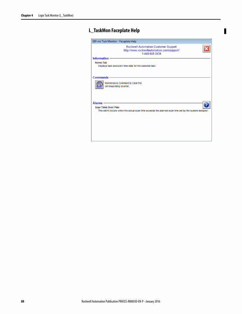
Chapter 4 Logix Task Monitor (L_TaskMon)
L_TaskMon Faceplate Help
88 Rockwell Automation Publication PROCES-RM003D-EN-P - January 2016
Chapter 5
Logix Module Status (L_ModuleSts)
The L_ModuleSts (Logix Module Status) Add-On Instruction monitors the connection status of one module in the I/O configuration tree of the Logix controller. The instruction provides an I/O fault signal if the connection is not ‘running’.
No visualization elements are supplied with the L_ModuleSts instruction.
Guidelines Use this instruction if you want to monitor the I/O connection status of a given module.
Do not use this instruction in these situations:• RSLogix 5000 or Studio 5000 Logix Designer software versions 23 or
earlier. This instruction only works in Logix software/firmware version 24 or later.
• This instruction is not required with the 1794-IF8IHNFXT FlexXT 8-channel Isolated HART Analog Input module. The I_1794IF8IHNFXT instruction already provides this functionality.
IMPORTANT The Logix Module Status Add-On Instruction is for use with Studio 5000 Logix Designer (software and Logix controller firmware) version 24 or later.
Rockwell Automation Publication PROCES-RM003D-EN-P - January 2016 89
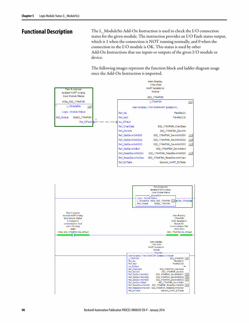
Chapter 5 Logix Module Status (L_ModuleSts)
Functional Description The L_ModuleSts Add-On Instruction is used to check the I/O connection status for the given module. The instruction provides an I/O Fault status output, which is 1 when the connection is NOT running normally, and 0 when the connection to the I/O module is OK. This status is used by other Add-On Instructions that use inputs or outputs of the given I/O module or device.
The following images represent the function block and ladder diagram usage once the Add-On Instruction is imported.
90 Rockwell Automation Publication PROCES-RM003D-EN-P - January 2016
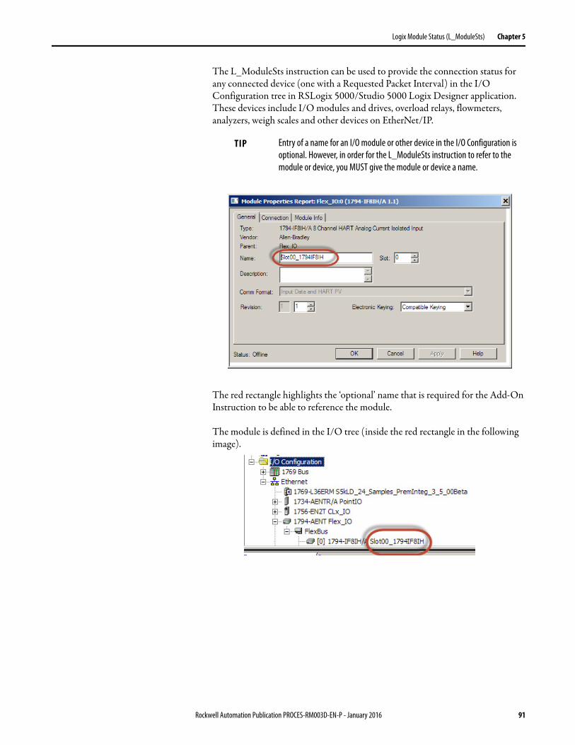
Logix Module Status (L_ModuleSts) Chapter 5
The L_ModuleSts instruction can be used to provide the connection status for any connected device (one with a Requested Packet Interval) in the I/O Configuration tree in RSLogix 5000/Studio 5000 Logix Designer application. These devices include I/O modules and drives, overload relays, flowmeters, analyzers, weigh scales and other devices on EtherNet/IP.
The module is defined in the I/O tree (inside the red rectangle in the following image).
TIP Entry of a name for an I/O module or other device in the I/O Configuration is optional. However, in order for the L_ModuleSts instruction to refer to the module or device, you MUST give the module or device a name.
The red rectangle highlights the ‘optional’ name that is required for the Add-On Instruction to be able to reference the module.
Rockwell Automation Publication PROCES-RM003D-EN-P - January 2016 91
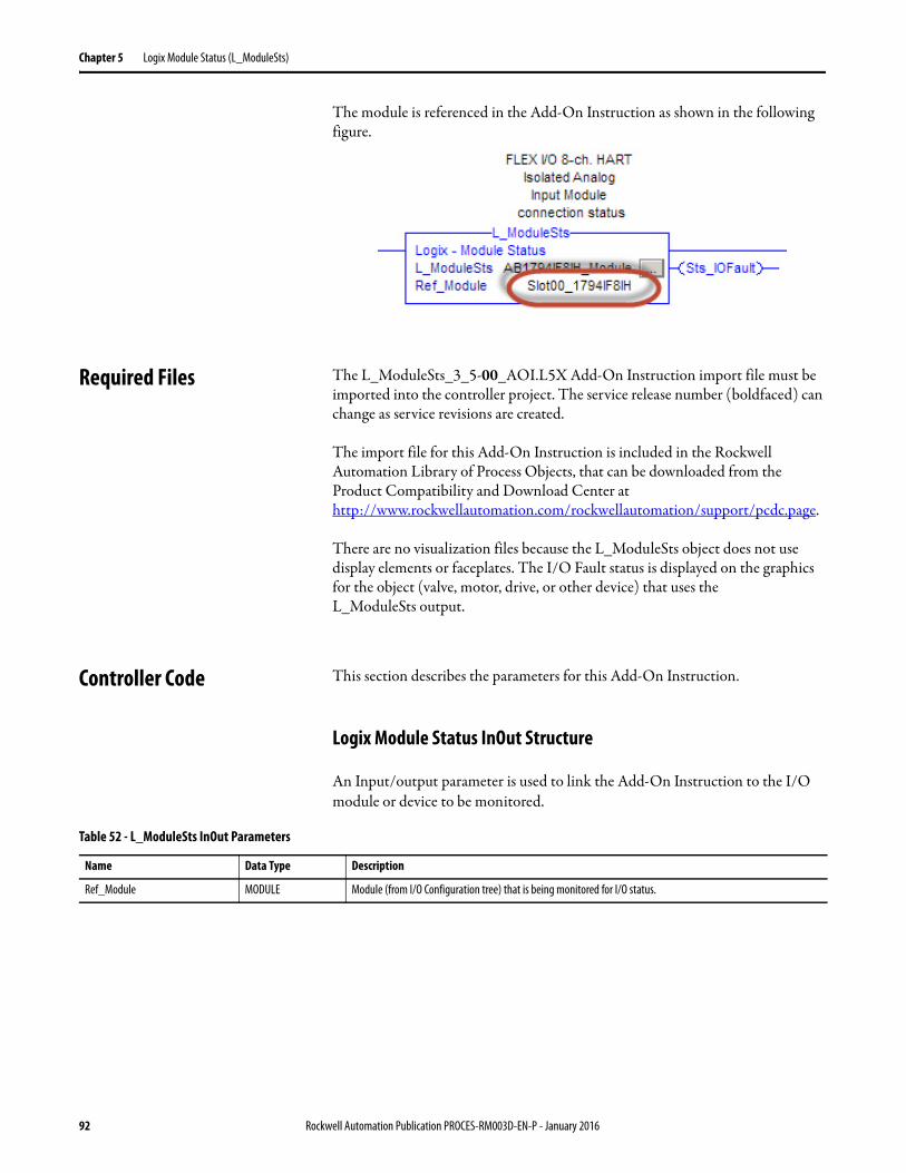
Chapter 5 Logix Module Status (L_ModuleSts)
The module is referenced in the Add-On Instruction as shown in the following figure.
Required Files The L_ModuleSts_3_5-00_AOI.L5X Add-On Instruction import file must be imported into the controller project. The service release number (boldfaced) can change as service revisions are created.
The import file for this Add-On Instruction is included in the Rockwell Automation Library of Process Objects, that can be downloaded from the Product Compatibility and Download Center at http://www.rockwellautomation.com/rockwellautomation/support/pcdc.page.
There are no visualization files because the L_ModuleSts object does not use display elements or faceplates. The I/O Fault status is displayed on the graphics for the object (valve, motor, drive, or other device) that uses the L_ModuleSts output.
Controller Code This section describes the parameters for this Add-On Instruction.
Logix Module Status InOut Structure
An Input/output parameter is used to link the Add-On Instruction to the I/O module or device to be monitored.
Table 52 - L_ModuleSts InOut Parameters
Name Data Type Description
Ref_Module MODULE Module (from I/O Configuration tree) that is being monitored for I/O status.
92 Rockwell Automation Publication PROCES-RM003D-EN-P - January 2016
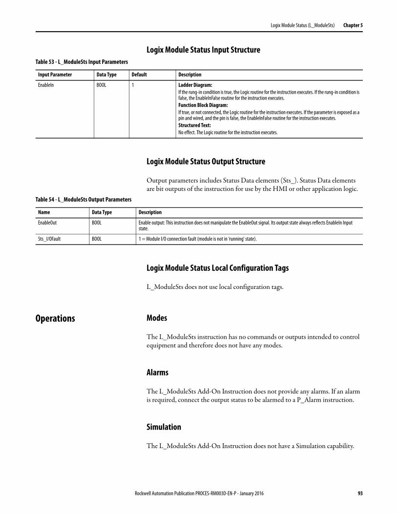
Logix Module Status (L_ModuleSts) Chapter 5
Logix Module Status Input Structure
Logix Module Status Output Structure
Output parameters includes Status Data elements (Sts_). Status Data elements are bit outputs of the instruction for use by the HMI or other application logic.
Logix Module Status Local Configuration Tags
L_ModuleSts does not use local configuration tags.
Operations Modes
The L_ModuleSts instruction has no commands or outputs intended to control equipment and therefore does not have any modes.
Alarms
The L_ModuleSts Add-On Instruction does not provide any alarms. If an alarm is required, connect the output status to be alarmed to a P_Alarm instruction.
Simulation
The L_ModuleSts Add-On Instruction does not have a Simulation capability.
Table 53 - L_ModuleSts Input Parameters
Input Parameter Data Type Default Description
EnableIn BOOL 1 Ladder Diagram:If the rung-in condition is true, the Logic routine for the instruction executes. If the rung-in condition is false, the EnableInFalse routine for the instruction executes.Function Block Diagram:If true, or not connected, the Logic routine for the instruction executes. If the parameter is exposed as a pin and wired, and the pin is false, the EnableInFalse routine for the instruction executes.Structured Text:No effect. The Logic routine for the instruction executes.
Table 54 - L_ModuleSts Output Parameters
Name Data Type Description
EnableOut BOOL Enable output: This instruction does not manipulate the EnableOut signal. Its output state always reflects EnableIn Input state.
Sts_I/OFault BOOL 1 = Module I/O connection fault (module is not in ‘running’ state).
Rockwell Automation Publication PROCES-RM003D-EN-P - January 2016 93
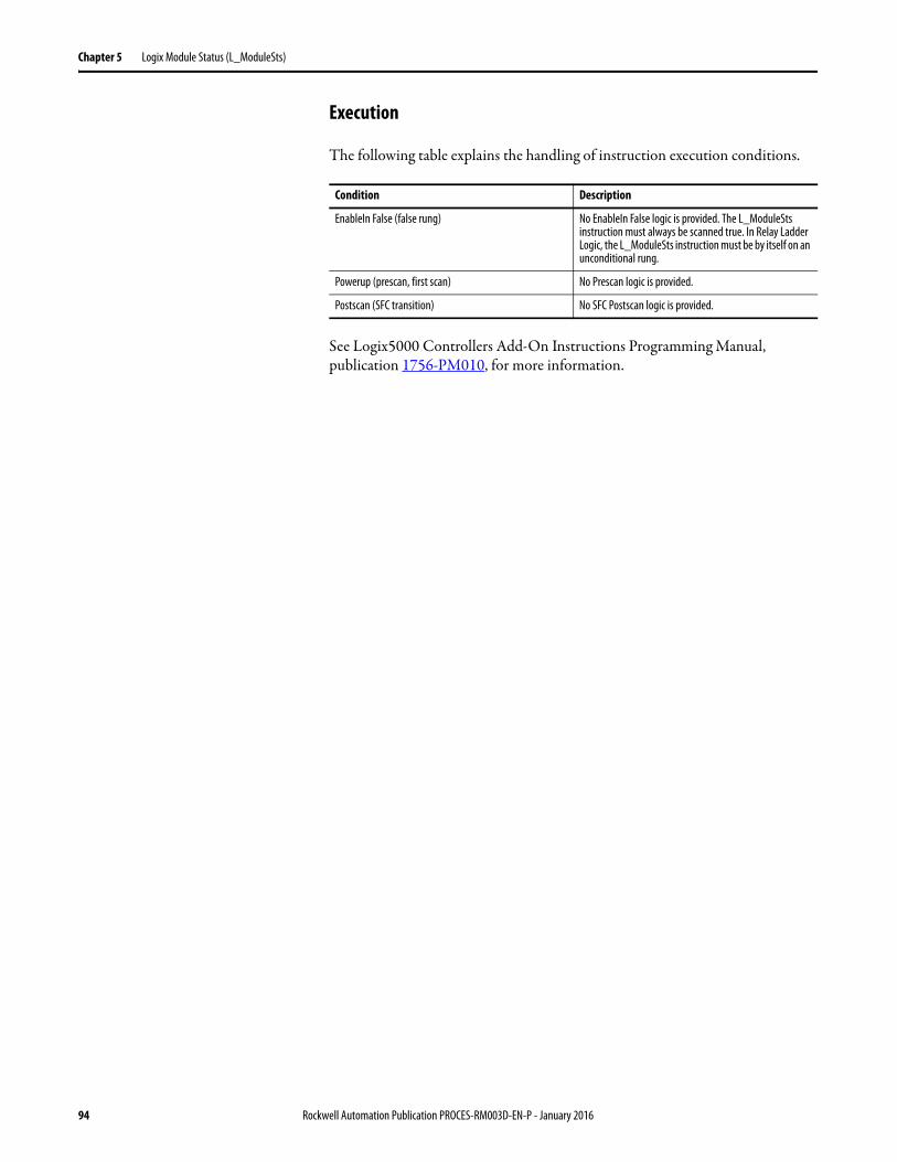
Chapter 5 Logix Module Status (L_ModuleSts)
Execution
The following table explains the handling of instruction execution conditions.
See Logix5000 Controllers Add-On Instructions Programming Manual, publication 1756-PM010, for more information.
Condition Description
EnableIn False (false rung) No EnableIn False logic is provided. The L_ModuleSts instruction must always be scanned true. In Relay Ladder Logic, the L_ModuleSts instruction must be by itself on an unconditional rung.
Powerup (prescan, first scan) No Prescan logic is provided.
Postscan (SFC transition) No SFC Postscan logic is provided.
94 Rockwell Automation Publication PROCES-RM003D-EN-P - January 2016

Publication PROCES-RM003D-EN-P - January 2016Supersedes Publication PROCES-RM003C-EN-P - August 2014 Copyright © 2016 Rockwell Automation, Inc. All rights reserved. Printed in the U.S.A.
Rockwell Automation Support
Rockwell Automation provides technical information on the Web to assist you in using its products.At http://www.rockwellautomation.com/support you can find technical and application notes, sample code, and links to software service packs. You can also visit our Support Center at https://rockwellautomation.custhelp.com/ for software updates, support chats and forums, technical information, FAQs, and to sign up for product notification updates.
In addition, we offer multiple support programs for installation, configuration, and troubleshooting. For more information, contact your local distributor or Rockwell Automation representative, or visithttp://www.rockwellautomation.com/services/online-phone.
Installation Assistance
If you experience a problem within the first 24 hours of installation, review the information that is contained in this manual. You can contact Customer Support for initial help in getting your product up and running.
New Product Satisfaction Return
Rockwell Automation tests all of its products to help ensure that they are fully operational when shipped from the manufacturing facility. However, if your product is not functioning and needs to be returned, follow these procedures.
Documentation Feedback
Your comments will help us serve your documentation needs better. If you have any suggestions on how to improve this document, complete this form, publication RA-DU002, available at http://www.rockwellautomation.com/literature/.
United States or Canada 1.440.646.3434
Outside United States or Canada Use the Worldwide Locator at http://www.rockwellautomation.com/rockwellautomation/support/overview.page, or contact your local Rockwell Automation representative.
United States Contact your distributor. You must provide a Customer Support case number (call the phone number above to obtain one) to your distributor to complete the return process.
Outside United States Please contact your local Rockwell Automation representative for the return procedure.
Rockwell Otomasyon Ticaret A.Ş., Kar Plaza İş Merkezi E Blok Kat:6 34752 İçerenköy, İstanbul, Tel: +90 (216) 5698400
Rockwell Automation maintains current product environmental information on its website athttp://www.rockwellautomation.com/rockwellautomation/about-us/sustainability-ethics/product-environmental-compliance.page.